1
OPERATING MANUAL
1
ApexNRG•Rider
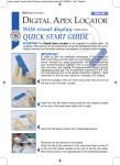
The Digital Apex Locator is designed to meet international safety
and performance standards. Personnel operating the instrument
must have a thorough understanding of the proper operation of the
instrument. These instructions have been prepared to aid medical and
technical personnel to understand and operate the instrument. Do
not operate the instrument before reading this manual and gaining
a clear understanding of the operation of the instrument. If any part
of this manual is not clear, please contact your representative for
clarification.
The ApexNRG-Rider calculates the distance from the tip of your
endodontic file to the Major Apical Foramen by using multi-frequency
currents.
The ApexNRG-Rider measures the response of the root canal between
two electrodes, depending on the frequency. The first electrode is the
lip hook (3) (Pic.A). The second is the mini file holder (2) which makes
contact with a file that has been inserted into the root canal.
The ApexNRG-Rider monitors the changes in the canal's response as
the file probe approaches the apex.
Technologically Advanced:
• There are 6 LEDs to mark the advancement of the file, for precise
working length measurement.
• The use of DSP allows a much higher level of accuracy and
control of the process with measurement results accurate to 0.1
mm in apical region and a display resolution of 0.25 mm in the
critical measurement range.
• The ApexNRG-Rider provides precise measurements of the canal
under all conditions, including wet, dry and bleeding canals. You
can immediately measure another canal, without any special
preparation.
• Calibration is automatic. No manual calibration is required.
• Can be muted!
3
Initial Setup
The ApexNRG Rider is a multi-purpose device used to measure the working
length of the root canal. It can be used in three modes:
"Manual" as a stand alone apex locator.
"Riding" on a rotary handpiece
"Satellite" connected but unattached to the handpiece
Manual Mode
Manual Mode Installation
4
1. Remove the protective plastic tab that
insulates the battery from contact by pulling
out firmly.
Pic.A1
2.Insert the two main lead wires into the outlets
at the top of the Digital Apex Locator. (Pic.A1)
3.Insert the file clip and lip hook into the
sockets located at the end of the lead wires
(either left or right). (Pic.A2 + A3)
Pic.A2
4.Attach the apron clasp to the lead wires by
inserting them into the two wire holders on
the clasp handles (Pic.A4)
5.Insert the Digital Apex Locator into a
disposable sleeve. (Pic.A5)
6.Place the Digital Apex Locator near the mouth
of the patient, and attach the clasp to the
apron. (Pic.A6)
Pic.A3
7.Place the lip hook located at the end of the
lead wire on the lower lip, preferably on the
opposite side of the tooth being treated.
8.Place the file at the entrance to the canal and
then connect it to the mini file holder located
at the end of the file clip cable.
Pic.A4
9.To activate the Rider, make contact between
the lip hook and the file. (Pic.A7)
The Digital Apex Locator is now ready for
manual operation.
Pic.A5
Pic.A7
Pic.A6
5
Riding Mode
1
2 Strap
A
3 Adaptor
6
Riding Mode Installation
1. Connect the strap 2 to the adaptor 3 . Use
the strap size (22-25 or 24-27), best suited to
the micro-motor diameter. (Pic.B1)
2. Place the adaptor 3 on the micro-motor,
positioning the metal tab A on the E-type
connector (Pic.B2), while pushing the adaptor
tab toward the micro-motor, ensuring a snug fit
to the handle.
3. Secure the strap around the micro-motor by
placing the two pins on either side of the strap
into place. (Pic.B3)
4. Remove the protective plastic tab that insulates
the battery from contact by pulling out firmly.
Complete assembly by sliding the Rider 1 into
its track on the adaptor.
(Pic.B4)
5. Connect the handpiece to the micro-motor.
(Pic.B5)
6. Connect the lead wire, to be used with the lip
hook, to the pin on the right side of the device
(the side with the LEDs and the printed lip hook
symbol
). (Pic B6)
7. Insert the lip hook into the socket located at the
end of the lead wire. (Pic.B7)
8. Place the lip hook located at the end of the lead
wire on the lower lip, preferably on the opposite
side of the tooth being treated.
9. Insert a file into the handpiece and lock into
place.
10.To activate the Rider, make contact between
the lip hook and the file. (Pic.B8) or the rubber
dam clamp
The Rider is now ready for operation.
Pic.B8
Pic.B7
Pic.B1
3
Pic.B2
A
Pic.B3
Pic.B4
1
Pic.B5
Pic.B6
7
11.To verify conductivity between the handpiece and the Rider Digital Apex
Locator, connect the 0.5 Validation Cable to the Rider Digital Apex Locator.
Make contact between the endo file and the lip hook cable.
The 0.5 LED on the Rider Digital Apex Locator should light, verifying the
conduction of the electric current between the Rider Digital Apex Locator and
the endo file, allowing accurate measurement of canal length.
Satellite Mode
3 Adaptor
8
4 Satellite connector
Satellite Mode Installation
1. Follow steps 1-6 in section B (Assembled
Mode)
Pic.C1
2. Insert the pin (plug) of the extension cable
into the hole in the satellite connector.
(Pic.C1)
3. Slide the satellite connector 4 into place
on the adaptor 3 assembled on the Rider
device.
Pic.C2
4.Connect the cable's socket to either the right
or left pin of the apex locator. (Pic.C3)
5. Insert the lip hook to the socket at the end of
the lead wire and connect it to to the pin on
the device (either left or right). (Pic.C4)
6. Insert the Rider into a disposable sleeve.
(Pic.C5)
Pic.C3
7. Place the lip hook located at the end of the
lead wire on to the lower lip, preferably on the
opposite side of the tooth being treated.
8. To activate the Rider, make contact between
the lip hook and the file. (Pic.C6) or the rubber
dam clamp
Pic.C4
9. Ensure conductivity according to step 11 in
"Riding" mode
Pic.C5
Pic.C6
9
Directions For Use
NOTE: The Rider-Digital Apex Locator should be used only as an adjunct
to normal endodontic procedures. While the unit can reduce the number of
radiographs necessary, an initial radiograph must be taken to estimate working
length. Clinical judgment, including knowledge of root canal anatomy is
paramount when interpreting results.
1.Activate the Digital Apex Locator making contact between the lip hook and
the file or the rubber dam clamp. Once activated, the LEDs will flash in
sequence as a “self-check”.
2.Following this check, the "2.00" green LED will blink, indicating the Digital
Apex Locator is in stand by mode.
3.When the file reaches the "2.00" mm point, the green LED will stay lit and a
very slow beep will sound.
4.Work the file towards the apex, passing LEDs “1.00” (green), “0.50” and
“0.25” (orange).
NOTE: In order to gain the maximum advantage of this advanced DSP
technology, the file must be manipulated in slow movements towards the
apical constriction (APEX) in clockwise and counterclockwise motions. This
is due to the extremely high accuracy and rapidity of measurement of each
minute movement of the file. This is especially important in the critical area
between 0.5 to the apical constriction (APEX). Swift movement of the file may
cause an unsteady LED display.
10
The frequency of the alarm increases as the file nears the apical constriction.
This is a particularly sensitive area when working with a handpiece, and use of
a file beyond this point requires great caution. To allow accurate measurement,
continuous contact must be maintained between the file and the side of the
canal. When the file reaches the apical constriction, the red “APEX” LED lights
and the warning alarm reaches a higher frequency. If the file passes the apical
constriction the warning alarm will reach the highest pitch and frequency and the
“-0.00” (past apex) LED will flash. At this stage, gently pull file back out of the
canal until the “APEX” red LED lights and the alarm sound slows its pitch.
5. When the file reaches the apical constriction, the red “APEX” LED will light.
6. Mark the length of the canal with the rubber stopper. Measure the length of
the file and prepare the rest of the files for the treatment according to this
length.
NOTE: In order to fully prepare the canal using the handpiece and rotary files,
keep the Rider Digital Apex Locator on and in measuring mode (connected),
to ensure that the apex is not perforated. It is imperative to keep the irrigation
solutions within the confines of the canals. The pulp chamber must be dry.
7. The audio default is ON. As the measurement process can take 3-5 minutes,
with the audible alarm constantly beeping, the device can easily be muted at
your convenience. To mute, make continuous contact between the file and
the lip hook, when both are connected to the device. After 6 seconds, the
"passed apex" alarm will stop and two short beeps will sound. To re-activate,
perform the same action and the device will emit a short tune. In any case,
when the apex is reached or passed, an audible alarm will sound as a safety
feature.
Please refer to our recommendations for a successful treatment (page 14) and
our troubleshooting guide (page 17) for more information.
ATTENTION: The intended use of the rubber sleeve is to avoid a “false positive”
reading that might occur in the extreme cases when using a rubber dam is not
medically feasible, when the handpiece makes contact with the soft tissues (lip,
tongue, etc).The rubber sleeve is not a replacement for the rubber dam and
may not, by any means, serve as an alternative for the rubber dam, which is
mandatory in endodontic procedures. The rubber sleeve is a single use item and
should be disposed after use to prevent cross infection. It cannot be sterilized.
11
Device Power Off
As an energy-conservation feature, the Digital Apex Locator will turn off after
5 Min. of inactivity.
Battery Power
Due to extended and intensive work with the handpiece, the battery life is limited.
However, regular use as a manual EAL will allow many treatments per battery. A
spare battery is included with the device.
When the Digital Apex Locator recognizes low battery power, upon turning on
the unit, three intermittent LED lights will light simultaneously along with beeping
sounds. This is a warning to change the battery soon (still functional). If after an
additional period of time the operator has not changed the battery, the unit will
turn off automatically upon being turned on and will not allow the operator to use
the unit. Replace the battery immediately. There are no other user serviceable
items within the unit.
Warning! Low battery power affects accuracy.
Please note that the "Tilt" muting feature may not work when the battery power
is too low.
Note: When storing the Digital Apex Locator for an extended period of time
without use, it is recommended to remove the battery from the device in order
to lengthen the battery life. The battery may also leak after a long period of
disuse, damaging the device and voiding the warranty.
12
Battery Replacement
1.Turn over the device so the back side is facing you.
2.Using a fingernail, gently pull out the battery drawer and remove the battery
(pic.D, E, F).
3.Remove the battery from the drawer (Pic.G) and replace with a fresh battery
(type CR2450).
4.Be sure to insert the battery with the + sign facing upwards, to the bottom of
the device. (Pic.H)
5.Slide the drawer back into the battery housing, until it clicks. (Pic.I)
Dispose of depleted battery in accordance to local regulations.
Pic.D
Pic.E
Pic.F
Pic.G
Pic.H
Pic.J
13
Sterilization
Warning! Do not place the Digital Apex Locator into the Autoclave!!
Do not submerge the device or allow liquid to enter the unit enclosure!
Attention! The Digital Apex Locator is not supplied in a sterile state. All surfaces
of the device and its accessories should be disinfected when the unit is initially
received and thereafter between procedures, to prevent cross-infection. Wipe
the surface of the unit with a clean cloth moistened in 70% ethyl alcohol solution.
The main lead wires, mini file holder, lip hook traditional file clip, mini sensor
probe and apron clasp can be sterilized in the autoclave at 121ºC for 20 minutes
or at 134ºC for 5 minutes, or according to the manufacturer's instructions.
Only accessories specifically mentioned as autoclave save may be sterilized in
the autoclave.
For your convenience After the length of the
canal has been defined and marked on all of
the files, the compact and convenient Sensor
Probe can be used to confirm the depth of
the entering file during the procedure.
The result of the momentary contact with
the file will be shown on your apex locator
immediately.
Please note: Contact should be made increasingly often when
approaching the biological apex, in order to prevent perforation.
The location of the file will be shown on the apex locator only
during direct contact with the sensor probe.
Important! MedicNRG does NOT supply endodontic files.
Please note the endo files used, whether NiTi (rotary) or Stainless Steel (manual)
should be sterilized or replaced according to the manufacturer's instructions.
Single use files should be discarded according to the manufacturer's instructions.
Standard, off the shelf, endo files may be used with the Rider apex locator,
except for anodize coated files, which will interrupt the current between the
canal and the apex locator.
14
Recommendations for a successful treatment
Prior to measuring root canal length with your
Digital Apex Locator:
• Make sure that the pulp chamber 1 is dry before
inserting the measuring file. It is recommended to dry
the pulp chamber with a cotton pellet or by a slight
aspiration of the moisture with an aspiration syringe.
Also ensure that all canals are isolated from each
other. Excessive fluids in the pulp chamber or canals
may form a conductive bridge between canals or with
a metallic restoration or crown. Drying the canal with
a paper point may help increase accuracy.
• When the walls of the pulp chamber are damaged 2 , or there are damaged
fillings 3 , saliva leakage can occur from the oral cavity, which will prevent
drying of the chamber. A moist chamber may cause the immediate formation
of a closed electrical circuit, i.e., a short circuit. In this event, the apex locator
will issue a warning (flashing red LED and audible alarm) as if it reached the
apex (false positive reading). In such cases the missing chamber wall should
be temporarily restored, but only with nonconductive materials such as
Composite, IRM, GI (glass iononer), etc. After restoration, a dry chamber can
be achieved and accurate measurement can be reached.
• Check that any damaged fillings 3 have been removed in order to prevent
marginal leakage. Such leakage will result in a moist working area and may
interfere with the Digital Apex Locator’s reading. The red light will flash,
indicating that it has identified the apex when in fact, the file is only at the
canal entrance area.
• Continuous contact with metal or amalgam fillings will ground the device, so
take special care to prevent contact between the file and any existing metalbased restoration of the tooth by amalgam filing or metal crown. In such
instances, an adequate isolation of the file from the metallic environment can
be achieved by fitting 2-3 rubber stoppers onto the part of the file that may
contact the metal of the restoration.
• A preliminary extirpation is recommended before beginning measurement.
Residual tissue may result in a premature and erroneous reading.
15
• When using a rubber dam, make sure that it is properly sealed around the
insertion area. Any aperture between the rubber dam and tooth can be sealed
with a temporary restoration. Leading endodontists recommend the use of
rubber dams during every root canal treatment.
• Ensure the lip hook fully contacts the patient’s moist mucosa. The lip hook
should not make contact with any adjacent teeth, which may have metal
fillings.
• Check all connections.
• While some of the accessories are autoclavable, if any accessory seems
damaged after a number of autoclave cycles, please replace with a new part.
Particularly check the lead wire cables. (see the section on "sterilization" for a
full list of the autoclavable items).
Recommendations for the measurement process
Prepare a wide canal orificium and prepare the first 2/3 in a tapered way to
prevent contact with premature constrictions in the canal.
• The file should be inserted into the canal in a filing motion (clockwise and
counter-clockwise). Rotation of the file in one direction may cause the file to
break inside the canal!
• Take care to ensure continuous contact between the file and the root canal
wall. It is recommended to use the largest possible file that will reach the
estimated working length. A loose file that does not make continuous contact
with the canal wall will be unable to perform accurate measurements.
• Ensure continuous and strong contact between the file and its holder (this may
be problematic with the thinner files 6, 8, 10 mm).
• In excessively desiccated canals, moistening is recommended to improve
conductivity. This can be performed by slight irrigation and/or by slight
lubrication of the file.
• If the canal is too dry, introduce NaOCl to the apical third of the canal.
16
Exceptions
• In a very wide canal, the Digital Apex Locator may be able to read the
measurement only at the tip where the canal constricts toward the apical
foramen. In such cases only a depth of 0.5 mm and apical foramen, will be
identified. Reading may be improved by using a larger file and making definite
contact with the canal wall.
• The apex locator reading may be unstable in the following tooth pathology
situations: decay (caries in the pulp chamber), strong bleeding in the canal,
metallic restoration, periapical lesion, open apex 4 , excessively wide canal.
• Bone or periodontal ligament loss (indicated by a radiolucency on the film) can
cause inaccurate readings.
• A worn out battery will reduce the accuracy of the reading. The battery should
be replaced as soon as the instrument's warning signal appears, as detailed in
the user manual. Take care to follow the instructions for connecting the cables
to the instrument as specified in the user manual.
• The Digital Apex Locator is a digital electronic device and as such requires
a minimum residual battery voltage to drive the circuitry. It therefore requires
replacement when this point has been reached even thought there may be
sufficient power left for the LEDs to turn on.
• In all instances of erroneous readings as described above only a premature
reading situation is possible, due to ostensible recognition of the apex.
However, the Digital Apex Locator will not show a delayed reading that may
endanger the periapical tissues.
17
Troubleshooting
Question
The “Rider” is assembled on the
micro-motor but no reading is
being given.
Make sure the following are correctly
assembled:
A. The adaptor’s metal tab is touching
the micro-motor’s E-type connection.
B. The Rider is assembled all the way to
the end of the adaptor’s track.
C. The endo file is firmly locked into place
in the handpiece.
D. The lead wire is connected to the pin
on the right side of the device (the side
with the LEDs). See pic. B6
E. The endo file may be anodize-coated,
isolating the current.
Please change to a different type of file,
and re-try.
The “Rider” is un-assembled on
the micro-motor and no reading is
being given
If you wish to make a measurement using
the satellite connector, make sure the
following are correctly assembled:
A. The adaptor’s metal tab is touching the
micro-motor’s E-type connection.
B. The satellite connector is assembled all
the way to the end of the adaptor’s track.
C. The endo file is firmly locked into place
in the handpiece.
D. The extension cable’s pin is firmly
inserted into the satellite connector’s hole.
See pic. C2.
E. The endo file may be anodize-coated,
isolating the current. Please change to a
different type of file, and re-try.
Unit shows a display of LEDs
when the file has only just been
introduced to the canal.
18
Solution (see user manual for fuller explanations)
The device has recognized the entrance
to the canal and is searching for the exact
location. The device will stabilize within a
few seconds and you may begin
measuring the canal.
Question
Solution (see user manual for fuller explanations)
Unit shows that the file is at the
apex when instrument has only
just been introduced to the canal
("false positive").
The correct reading should be applied
starting from the apical part of the tooth
only. Handpiece (in riding or satellite
mode) is touching soft tissue. Ensure use
of a rubber dam to avoid this contact.
Either pulp chamber floor is not
completely dry or the file has contacted
a metallic restoration. In either case, the
inaccurate readings are due to shorting
the circuit.
Dry the pulp chamber if it is wet.
Reading on unit is not steady.
File is in intermittent contact with the
canal walls. Either place a curve at the tip
of the file or try a larger size file so the tip
touches the wall near the apex.
The nature of the work with a handpiece
dictates continual movement, so as not
to overload stress on the file, reducing
the danger of breakage. This continual
movement is constantly read by the
Rider, giving the impression that it
is unstable. However, it is actually
displaying actual file movements, on-line.
For the steadier readings of the working
length measurement it is recommended
to irrigate the canal sequentially using
sodium hypochlorite and EDTA (17%)
solution and perform instrumentation with
the canals filled with EDTA.
Handpiece (in riding or satellite mode)
is touching soft tissue. Ensure use of a
rubber dam to avoid this contact.
19
Question
20
Solution (see user manual for fuller explanations)
The file is advancing in the canal
and no reading is being given.
The device begins measuring 2 mm
before the apical constriction. Check the
following:
A. The existence of an extremely long
canal.
B. The file is not making contact with the
canal walls, a requirement for canal
measurement. Change to a larger file.
C. The canal may be extremely
desiccated (dry) – introduce a lubricant
into the canal.
No lights show.
Make sure you have closed the device’s
circuit by making contact with the two
electrodes (lip hook and file). The lip hook
can also turn on the unit when making
contact with the handpiece chuck, after it
has been assembled on the micro-motor.
• Make sure the adaptor’s metal tab is
touching the micro-motor’s E-type
connection.
• Battery is empty or has not been
replaced correctly (see battery
replacement instructions)
3 LEDs illuminate simultaneously.
Warning to replace battery as soon as
possible.
The reading on the device does
not coincide with the result of the
X-ray.
The X-ray is a two-dimensional image
which cannot accurately find the apical
constriction. Therefore, the result of the
apex locator should be relied upon for
determining the correct working length.
In addition, bone or periodontal ligament
loss (indicated by a radiolucency on the
film) can cause inaccurate readings
The unit will not switch off.
Battery is low. Replace battery.
Question
Solution (see user manual for fuller explanations)
Unit does not work when battery
has been replaced.
Please check each of the following points:
A. The battery has been placed upside
down.
B. The battery was not fresh. Please
ensure you are replacing with a new
battery.
C. Please make sure you are using a
CR2450 type battery.
The battery drawer will not slide
back into place.
There is only one direction in which the
drawer can be replaced. If it cannot be
replaced, flip the drawer over and retry.
The adaptor strap will not close
around the micro-motor.
There are different sized straps –
please make sure you are using the
correct size.
Pull the strap tightly around the micromotor handle and snap the pins in place
on the adaptor.
Audible alarm does not sound.
Ensure the following:
A. You have reached the 2.00 mm mark
or lower in the canal (via LED display).
B. The device has been muted. Tilt the
device 1800 to reactivate the sound.
C. Battery is too low. Replace with new
battery.
I have muted the device but it still
beeps.
When the apical constriction is reached
or passed, the device will emit an audible
alarm as a safety feature.
Compatible with the following handpieces:
Most standard E-type connections - using the standard kit supplied.
Using a special adaptor kit (sold separately):
Dentsply X-Smart, NSK EndoMate, SybronEndo EndoTouch, Brasseler USA
EndoSequence II, SybronEndo TCM Endo III.
21
Included in box
• Digital Apex Locator (1 unit)
• Lead Wires (4 units) - autoclave safe
• Apron Clasp (2 units) - autoclave safe
• Lip Hook (2 units) - autoclave safe
• Traditional File Clip - autoclave safe
• Mini File Holder (3 units) - autoclave safe
• Disposable Sleeves (20 units)
• Battery (type CR2450)
• Mini Sensor Probe (1 unit)- autoclave safe
• Extension cable (1 unit) - autoclave safe
• E-type adaptor (1 unit)
• Micro-motor handle strap (2 units)
• Satellite connector (1 unit)
• 0.5 Validation Cable (1 unit)
Accessories (not included)
Endo files not supplied. Please refer to the Sterilization section on page 13 for
more information.
In order to facilitate your operating area, MedicNRG has developed a wide range
of accessories that are fully compatible with the Digital Apex Locator
• Extension cables - autoclave safe
• Long Sensor Probe - autoclave safe
• Special adaptor kits for additional handpieces available. Contact your local
MedicNRG representative.
Classification
• Type BF applied part.
• IEC 601-1 Compliant Medical Equipment
• Internally powered equipment
• Continuous operation
• Device is not supplied in a sterile state.
• Ordinary protection against ingress of water is required
Technical Specifications
• Power Supply: Single CR2450 battery
• Power input: 2.4 – 3.0 V
• Maximum current: 12mA
• Operating temperature: +10ºC - +40ºC
• Humidity: 10% - 90% without condensation.
22
Cautions and Warnings
DANGER: Not for use in the presence of a flammable anesthetic mixture with air
or with oxygen or nitrous oxide. Non-AP and non-APG equipment.
WARNING: The Apex Locator should NOT be used on a patient with a pacemaker.
WARNING: Do not plug any connectors or pins on the file clip or probes into any
external power source, as it may cause a severe safety hazard to the patient.
WARNING: Only use the specified battery.
WARNING: Use of other accessories which are not authorized for use in connection with this device may cause malfunction and compromise patient safety.
CAUTION: This device has been investigated with regard to safety from electrical
shock and fire hazard as well as electromagnetic compatibility (EMC). The device
has not been investigated for other physiological effects.
CAUTION: For use by qualified and trained personnel only.
CAUTION: This device to be used in conjunction with other diagnostic procedures and not relied on exclusively.
CAUTION: Do not autoclave the unit.
CAUTION: This device has been tested and found to comply with EMC limits for
the Medical Device Directive 93/42/EEC as last amended by 2007/47/EC
EN 60601-1-2. These limits are designed to provide reasonable protection against
harmful interference in a typical medical installation. However, there is not guarantee that interference will occur in a particular installation. The device generates radio frequency and, if not installed and used in accordance with these instructions,
may cause harmful interference to other devices in the vicinity.
If this device does cause harmful interference with other devices, which can be
determined by turning the device off and on, the user is encouraged to try to correct the interference by one or more of the following measures:
• Reorient or relocate the receiving device
• Increase the separation between devices
• Consult the manufacturer for help
CAUTION: To reduce the risk of electrical shock do not remove cover. Refer servicing to qualified service personnel.
CAUTION: U.S. Federal Law restricts this device to sale by or on the order of a
healthcare professional.
CAUTION: contains parts and assemblies susceptible to damage by ElectroStatic
Discharge (ESD).
23
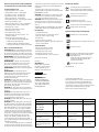
Symbols
0344
Corresponds to MDD 93/42/EEC as last amended by 2007/47/EC
Attention! Consult manual before use.
Type BF Patient Applied Part
Caution: contains parts and assemblies susceptible to damage by
ElectroStatic Discharge (ESD)
Packaging / Handling Symbols
Fragile, handle with care
Temperature limits for storage and transportation
Keep dry
Disposal in municipal waste may be restricted by state or local ordinance.
Dispose of in accordance with state and local regulations, or contact
manufacturer for guidance.
Compliance with specification
Test
Standard
Class/Severity level Test result
Emission
Radiated emission
Frequency range:
30-1000 MHz
clause 36.201.1 &
CISPR 11
Group 1 Class B
Complies
Immunity
Immunity from
Electrostatic
discharge (ESD)
clause 36.202.2 & 6 kV contact discharge
8kV air discharge
IEC 61000-4-2
Immunity
clause 36.202.3 &
from radiated
electromagnetic fields IEC 61000-4-3
24
Immunity from
power frequency
magnetic field
clause 36.202.8 &
IEC 61000-4-8
Complies
3.0 V/m,
80 MHz -2.5 GHz,
80% AM, 1 kHz
Complies
3 A /m @ 50Hz, 60Hz
Complies
NEDERLANDS
Rider digitale apexlocator
De Rider digitale apexlocator is zo ontworpen dat hij
aan internationale veiligheids- en prestatienormen
voldoet. Het personeel dat het instrument bedient
moet grondige kennis hebben van de juiste werking
van het instrument. Deze gebruiksaanwijzing is
opgesteld om medisch en technisch personeel te
helpen het instrument te leren kennen en bedienen.
Bedien het instrument niet voordat u deze handleiding
hebt gelezen en de werking van het instrument u
volledig duidelijk is. Als iets uit deze handleiding
niet duidelijk is, neem dan contact op met de
vertegenwoordiger voor opheldering.
De Rider digitale apexlocator geeft real-time
maatinformatie, zodat de tandarts het kanaal geheel
kan prepareren met een roterend handstuk. Dit maakt
preparatie van hoge kwaliteit van het kanaal in een
uniforme, conische vorm mogelijk, en hierdoor ook
betere desinfectie en obturatie van het gehele kanaal,
met inbegrip van het kritieke apicale derde deel.
De Rider digitale apexlocator meet de reactie van
het wortelkanaal tussen twee elektroden, afhankelijk
van de frequentie. De eerste elektrode is de liphaak.
De tweede is de endovijl die in het wortelkanaalis
ingebracht. De Rider digitale apexlocator controleert
de reactieveranderingen in het kanaal naarmate de
vijlprobe de apex nadert.
Gebruiksaanwijzing
NB: De Rider digitale apexlocator mag alleen worden
gebruikt als aanvulling op normale endodontische
procedures. Het is mogelijk dat er met dit instrument
minder röntgenfoto's nodig zijn, maar er moet wel een
eerste röntgenfoto worden genomen om de werklengte
te schatten. Klinisch oordeel, met inbegrip van kennis
van de anatomie van het wortelkanaal, is van groot
belang bij de interpretatie van de resultaten.
Verwijder het beschermende kunststof lipje dat de
batterij tegen contact afschermt, door er stevig aan te
trekken. Om de geleidbaarheid tussen het handstuk en
de Rider digitale apexlocator te controleren, sluit u de
0,5controlekabel aan op de Rider digitale apexlocator.
Maak contact tussen de endovijl en de liphaakkabel.
De 0,5 LED op de Rider digitale apexlocator moet gaan
branden. Dit bevestigt de geleiding van de elektrische
stroom tussen de Rider digitale apexlocator en de
endovijl, zodat de kanaallengte nauwkeurig kan
worden gemeten.
1. Trek de Rider disposable huls uit de verpakking
en schuif hem over de Rider digitale apexlocator.
De Rider disposable huls is voor eenmalig gebruik en
moet na gebruik worden afgevoerd om kruisbesmetting
te voorkomen. Hij kan niet worden gesteriliseerd.
2. De Rider digitale apexlocator wordt automatisch
geactiveerd wanneer de endovijl met de liphaak of
een rubberdamklem wordt aangeraakt. Wanneer de
apexlocator eenmaal geactiveerd is, knipperen
de LED's op volgorde als "zelfcontrole".
3. Na deze controle knippert de groene
LED '2.00' om aan te geven dat de Rider digitale
apexlocator in de stand-bymodus is.
4. Wanneer de vijl het '2.00' mm punt bereikt,
blijft de groene LED branden en klinkt er een zeer
langzame intermitterende pieptoon.
5. Werk de vijl naar de apex toe voorbij
LED's '1.00' (groen), '0.50' en '0.25' (oranje).
NB: Om zoveel mogelijk profijt van deze geavanceerde
DSP-technologie te krijgen, moet de vijl met langzame
bewegingen naar de apicale constrictie (APEX) worden
bewogen. Dit is vooral belangrijk in het kritieke gebied
tussen 0.5 en de apicale constrictie (APEX). Snelle
bewegingen van de vijl kunnen een onregelmatige
LED-weergave veroorzaken.
De frequentie van het alarm wordt hoger naarmate
de vijl de apicale constrictie nadert.
Dit is een bijzonder gevoelig gebied, vooral
wanneer met een handstuk wordt gewerkt, en
bij gebruik van een vijl voorbij dit punt is grote
voorzichtigheid geboden. Om nauwkeurige metingen
te verkrijgen, moet voortdurend contact tussen de vijl
en de zijkant van het kanaal worden gehandhaafd.
Wanneer de vijl de apicale constrictie bereikt, gaat
het rode LED-lampje 'APEX' branden en krijgt het
waarschuwingsalarm een hogere frequentie.
Als de vijl voorbij de apicale constrictie komt, bereikt
het waarschuwingsalarm de hoogste toonhoogte en
frequentie en knippert de LED '-0.00' (voorbij apex).
Op dit punt trekt u de vijl voorzichtig terug uit het
kanaal totdat het rode LED-lampje 'APEX' gaat branden
en het alarm een lagere toonhoogte krijgt.
6. Wanneer de vijl de apicale constrictie bereikt,
gaat de rode LED 'APEX' branden.
7. Markeer de lengte van het kanaal met de rubber
stop. Meet de lengte van de vijl en prepareer de rest
van de vijlen voor de behandeling volgens deze lengte.
8. De standaardinstelling voor geluid is AAN. Om het
geluid uit te schakelen, maakt u gedurende 6 seconden
voortdurend contact tussen de vijl en de lipklem,
wanneer beide op het instrument zijn aangesloten.
Na 6 seconden stopt het alarm 'voorbij apex' en klinken
er twee korte pieptonen. Om het geluid opnieuw te
activeren, voert u dezelfde handeling uit, waarna het
instrument een kort melodietje laat horen. In elk geval
klinkt er als veiligheidsmaatregel een hoorbaar alarm
wanneer u bij of voorbij de apex komt.
NB: Om het kanaal volledig met het handstuk en de
roterende vijlen te prepareren, houdt u de Rider digitale
apexlocator aan en in de meetmodus (aangesloten) om
te verzekeren dat de apex niet wordt geperforeerd.
De rubber stop is geen betrouwbaar genoeg obstakel
om perforatie van het periapicale weefsel te
verhinderen. Het is van groot belang te zorgen dat
de irrigatieoplossingen binnen de kanalen blijven.
De pulpakamer mag niet vol irrigatievloeistof zijn.
Instrument uitschakelen
Als energiebesparende maatregel schakelt de Rider
digitale apexlocator zichzelf uit nadat er ongeveer
90 seconden geen activiteit is geweest.
Batterijvermogen
WAARSCHUWING: Bij laag batterijvermogen
is de nauwkeurigheid minder. Wegens langdurig
en intensief werk met het handstuk is de levensduur
van de batterij beperkt. Bij regelmatig gebruik als
een handmatige elektronische apexlocator zijn er
echter vele behandelingen per batterij mogelijk. Er
wordt een extra batterij bij het instrument geleverd.
Wanneer de Rider digitale apexlocator waarneemt
dat het batterijvermogen laag is, gaan er drie
intermitterende LED-lampjes tegelijk branden en
klinken er pieptonen wanneer het instrument wordt
ingeschakeld. Dit is een waarschuwing om de batterij
snel te vervangen (functioneert nog wel). Als de
gebruiker na enige tijd de batterij niet heeft vervangen,
schakelt de Rider digitale apexlocator zichzelf
automatisch uit wanneer hij wordt aangezet zodat de
gebruiker het instrument niet kan gebruiken. Vervang
de batterij onmiddellijk. Er zijn geen andere door de
gebruiker te repareren onderdelen in het instrument.
WAARSCHUWING: Wanneer het instrument
gedurende lange tijd wordt opgeborgen, wordt
aangeraden de batterij te verwijderen om energie
te besparen. Het instrument verbruikt een kleine
hoeveelheid energie, zelfs wanneer het niet is
ingeschakeld, zodat de levensduur van de batterij
wordt verkort wanneer het niet wordt gebruikt.
De batterij kan na lange tijd niet gebruikt te zijn ook
gaan lekken, zodat het instrument wordt beschadigd
en de garantie wordt tenietgedaan.
Batterij vervangen
1. Draai de Rider digitale apexlocator om zodat
de achterkant naar boven wijst.
2. Trek de batterijlade voorzichtig naar buiten en
neem de batterij eruit. Vervang hem door een nieuwe
batterij (type CR2450).
3. Zorg dat u de batterij zo plaatst dat het
plusteken (+) omhoog wijst.
4. Schuif de lade weer in de batterijbehuizing tot
hij klikt.
Voer de lege batterij af volgens de plaatselijke
verordeningen.
Sterilisatie en desinfectie
WAARSCHUWING: Plaats de Rider digitale
apexlocator niet in de autoclaaf. Dompel de Rider
digitale apexlocator niet onder en zorg dat er geen
vloeistof in de kast van het instrument binnendringt.
ATTENTIE: De Rider digitale apexlocator wordt
niet steriel geleverd. Alle oppervlakken van de Rider
digitale apexlocator en de accessoires moeten bij
ontvangst van het instrument en daarna na elke
ingreep gedesinfecteerd worden om kruisbesmetting
te voorkomen. Veeg de buitenkant van het instrument
af met een schone doek die bevochtigd is met een
oplossing van 70% ethylalcohol.
De elektrodekabels, minivijlhouder, liphaak,
traditionele vijlklem, minisensorprobe en
patiëntenservetklem kunnen in de autoclaaf worden
gesteriliseerd bij 121 °C gedurende 20 minuten
of bij 134 °C gedurende 5 minuten, of volgens de
aanwijzingen van de fabrikant.
Alleen accessoires die specifiek worden genoemd
als autoclaafbestendig mogen in de autoclaaf worden
gesteriliseerd.
BELANGRIJK: Er worden geen endodontische vijlen
bij de Rider digitale apexlocator geleverd. Let op: de
gebruikte endovijlen, van NiTi (roterend) of roestvrij
staal (handmatig) moeten gesteriliseerd of vervangen
worden volgens de aanwijzingen van de fabrikant.
Vijlen voor eenmalig gebruik moeten worden afgevoerd
volgens de aanwijzingen van de fabrikant.
Standaard, in de handel verkrijgbare endovijlen
mogen met de Rider digitale apexlocator worden
gebruikt, behalve geanodiseerde gecoate vijlen,
die de stroom tussen het kanaal en de Rider digitale
apexlocator zullen onderbreken.
Nadat de lengte van het kanaal is bepaald en
op alle vijlen gemarkeerd, kan de diepte van de
ingebrachte vijl tijdens de ingreep worden bevestigd
met de compacte en handige sensorprobe.
Het resultaat van het kortstondige contact met de
vijl wordt onmiddellijk op de Rider digitale apexlocator
weergegeven.
NB: Er moet steeds vaker contact worden gemaakt
naarmate u de biologische apex nadert, om perforatie
te voorkomen. De plaats van de vijl wordt alleen op de
Rider digitale apexlocator weergegeven tijdens direct
contact met de sensorprobe.
ATTENTIE: Het beoogde doel van de rubber
huls is het vermijden van een 'vals-positieve'
waarde die kan optreden wanneer het handstuk
contact maakt met het zachte weefsel (lip, tong
enz.). De rubber huls is geen vervanging voor
de rubberdam en mag absoluut niet worden
gebruikt als alternatief voor de rubberdam, die
verplicht is bij endodontische ingrepen. De
rubber huls is voor eenmalig gebruik en moet na
gebruik worden afgevoerd om kruisbesmetting
te voorkomen. Hij kan niet worden gesteriliseerd.
De doos bevat
• Rider digitale apexlocator (1 stuk)
• Elektrodedraden (4 stuks) - autoclaafbestendig
• Patiëntenservetklem (2 stuks) - autoclaafbestendig
• Liphaak (2 stuks) - autoclaafbestendig
• Traditionele vijlklem - autoclaafbestendig
• Disposable hulzen (20 stuks) - uitsluitend voor
eenmalig gebruik
• Batterij (type CR2450) (2 stuks)
• Minisensorprobe (1 stuk) - autoclaafbestendig
• Verlengkabel (1 stuk) - autoclaafbestendig
• E-type houder (1 stuk)
• Handgreepband micromotor (2 stuks)
• Rubber connector (1 stuk)
• 0,5 controlekabel (1 stuk)
• Rubber handstukhulzen (5 stuks) - eenmalig gebruik
• Adapterkit voor niet-E-type handstukken
o Speciale houder zonder metalen lip
o Steun voor het contrahoekstuk
o Kabel om steun aan Rider te verbinden
oO
-ring om de kabel aan het handstuk te
bevestigen.
Waarschuwingen
GEVAAR: Niet voor gebruik in aanwezigheid van een
ontvlambaar anesthesiemengsel met lucht of met
zuurstof of distikstofoxide, apparatuur die niet van
categorie AP en niet van categorie APG is.
WAARSCHUWING: De Rider digitale apexlocator
mag NIET worden gebruikt bij een patiënt met een
pacemaker.
WAARSCHUWING: Sluit geen connectors of
pennen op de vijlklem of probes aan op een externe
voedingsbron, daar dit ernstig gevaar voor de veiligheid
van de patiënt kan opleveren.
WAARSCHUWING: Gebruik uitsluitend de opgegeven
batterij.
WAARSCHUWING: Gebruik van andere accessoires
die niet zijn goedgekeurd voor gebruik met de Rider
digitale apexlocator kan storing veroorzaken en de
veiligheid van de patiënt in gevaar brengen.
VOORZICHTIG: De Rider digitale apexlocator is
onderzocht op veiligheid wat betreft elektrische
schokken, brandgevaar en elektromagnetische
compatibiliteit (EMC). Het instrument is niet
onderzocht op andere fysiologische effecten.
VOORZICHTIG: Uitsluitend voor gebruik door bevoegd
en getraind personeel.
VOORZICHTIG: De Rider digitale apexlocator
dient te worden gebruikt in combinatie met andere
diagnostische procedures en men mag niet uitsluitend
hierop vertrouwen.
VOORZICHTIG: De Rider digitale apexlocator mag niet
geautoclaveerd worden.
VOORZICHTIG: De Rider digitale apexlocator is
getest en blijkt te voldoen aan de EMC-limieten
voor de Richtlijn medische hulpmiddelen 93/42/EEG,
het laatst gewijzigd door 2007/47/EG EN 60601-1-2.
Deze limieten zijn bedoeld om redelijke bescherming
te bieden tegen schadelijke interferentie in een
typische medische installatie. Er is echter geen
garantie dat er geen interferentie zal plaatshebben
in een bepaalde installatie. De Rider digitale
apexlocator genereert radiofrequentie en kan, als
hij niet geïnstalleerd en gebruikt wordt volgens deze
aanwijzingen, schadelijke interferentie bij andere
apparaten in de omgeving veroorzaken.
Als de Rider digitale apexlocator schadelijke
interferentie bij andere apparaten veroorzaakt, wat kan
worden bepaald door het instrument uit en weer aan
te zetten, wordt de gebruiker aangeraden te trachten
de interferentie te corrigeren door een of meer van de
volgende maatregelen:
• Het ontvangende apparaat draaien of verplaatsen
• De afstand tussen de apparaten vergroten
•
SybronEndo raadplegen voor assistentie
MedicNRG
VOORZICHTIG: Om het risico op elektrische schokken
te verminderen, het deksel niet verwijderen. Service
overlaten aan bevoegd servicepersoneel.
VOORZICHTIG: Volgens de federale wet van de VS is
verkoop van dit apparaat uitsluitend toegestaan aan of
op gezag van een professioneel zorgverlener.
VOORZICHTIG: bevat onderdelen en samenstellen die
gevoelig zijn voor beschadiging door elektrostatische
ontlading (ESD).
Symbooltoetsen
Classificatie
• Type BF patiëntdeel.
• Medisch hulpmiddel dat voldoet aan IEC 601-1
• Apparatuur met inwendige voeding
• Continubedrijf
• Instrument wordt niet steriel geleverd.
•N
ormale bescherming tegen binnendringend water
is vereist
Technische specificaties
• Voeding: Eén CR2450 batterij
• Opgenomen vermogen: 2,4 – 3,0 V
• Maximale stroom: 12 mA
• Bedrijfstemperatuur: +10 ºC – +40 ºC
• Vochtigheidsgraad: 10% – 90% zonder condensatie
Komt overeen met de Richtlijn medische
hulpmiddelen 93/42/EEG, laatst gewijzigd
door 2007/47/EG
0344
Attentie! Raadpleeg vóór gebruik de
handleiding.
0344
0344
0344 Type BF patiëntdeel
0344
0344
Voorzichtig: bevat onderdelen en
0344
samenstellen die gevoelig zijn voor
0344
beschadiging door
SN
SN
REF
SN / Hantering
Symbooltoets Verpakking
REF
-30C to 60C
-30C to 60C Temperatuurgrenzen voor opslag en vervoer
-30C to 60C
-30C to 60C
-30C to 60C
2
Voor eenmalig gebruik
MK-2URID05 (B)
Vervaardigd voor SybronEndo
1332 S. Lone Hill Ave., Glendora, CA 91740
800.346.3636 714.516.7979 SybronEndo.com
Vertegenwoordiging in Europa
Obelis s.a Europe
MedicNRG
Bd General
P.O.
Box 1261 Wahis 53
1030BG
Brussels
Belgium
4700
Roosendaal
Tel: +(32) 2 732-59-54
Nederland
Fax: +(32) 2 732-60-03
Fax +31-165-30 86 85
[email protected]
E-mail: [email protected]
Web: www.medicnrg.com/eu
TEST
Droog houden
Afvoer met gemeenteafval kan beperkt zijn
door landelijke of plaatselijke voorschriften.
Afvoeren volgens staats- en plaatselijke
voorschriften, of contact opnemen met de
fabrikant voor assistentie.
VERVAARDIGD IN ISRAËL
Fabrikant
MedicNRG Ltd.
Kibbutz Afikim 15148 ISRAEL
Fax: +972-4-675-4278
E-mail: [email protected]
Web: www.medicnrg.com
-30C to 60C
-30C to 60C
SN
SN
REF
SN
REF
REF
REF
REF
Breekbaar, voorzichtig
hanteren
SN
Copyright © 2010 van MedicNRG Ltd.
Alle rechten voorbehouden. Niets uit deze instructies
mag worden verveelvoudigd of gekopieerd in enige
vorm of op enige wijze, hetzij grafisch, elektronisch of
mechanisch, met inbegrip van fotokopiëren, typen of
retrievalsystemen zonder schriftelijke goedkeuring van
MedicNRG Ltd.
NORM
KLASSE/ERNST
TESTRESULTAAT
Clausule 36.201.1 &
CISPR 11
Groep 1 Klasse B
Voldoet
Immuniteit van elektrostatische
ontlading (ESD)
Clausule 36.202.2 en
IEC 61000-4-2
6 kV contactontlading
8 kV luchtontlading
Voldoet
Immuniteit van uitgestraalde
elektromagnetische velden
Clausule 36.202.3 en
IEC 61000-4-3
3,0 V/m, 80 MHz - 2,5 Ghz,
80% AM, 1 kHz
Voldoet
Immuniteit van frequentie
van magnetisch veld
Clausule 36.202.8 en
IEC 61000-4-8
3,0 A/m bij 50 Hx. 60 Hz
Voldoet
Emissie
Frequentiebereik
uitgestraalde emissie:
30-1000 MHz
Immuniteit
FRANÇAIS
Localisateur d'apex numérique Rider
Le Localisateur d'apex numérique Rider est conçu
pour répondre aux normes internationales de sécurité
et de performance. Le personnel qui utilise l’instrument
doit avoir une compréhension approfondie du
fonctionnement correct de l’instrument. Les présentes
instructions ont été préparées en vue d’aider le
personnel médical et technique à comprendre
et utiliser l’instrument. Ne pas utiliser l’instrument
avant de lire ce manuel et de bien comprendre le
fonctionnement de l’instrument. Si une partie
quelconque de ce manuel n’est pas claire,
demander des explications au représentant.
Le Localisateur d'apex numérique Rider fournit
des informations de mesure en temps réel, permettant
au dentiste de préparer complètement le canal au
moyen d’une pièce à main rotative. Cela permet de
bien conférer au canal une forme conique régulière,
pour mieux le désinfecter et l’obturer entièrement,
y compris dans son tiers apical critique. Le Localisateur d'apex numérique Rider mesure la réponse
du canal radiculaire entre deux électrodes, selon la
fréquence. La première électrode est le crochet labial.
La seconde est la lime d’endo que l’on a introduite
dans le canal radiculaire. Le Localisateur d'apex
numérique Rider surveille les variations de la réponse
du canal à l’approche de l’apex par la lime sonde.
Instructions d’utilisation
REMARQUE : Le Localisateur d'apex numérique
Rider ne doit être utilisé qu’en appoint des protocoles
endodontiques normaux. Si l’appareil permet de
réduire le nombre de radiographies nécessaires,
une radiographie initiale doit être prise pour estimer
la longueur utile. Une appréciation clinique, y compris
une connaissance de l’anatomie du canal est primordiale pour l’interprétation des résultats.
Retirer l’onglet plastique protecteur qui isole la
pile du contact en tirant fermement. Pour vérifier
la conductivité entre la pièce à main et le Localisateur
d'apex numérique Rider, connecter leCâble de
validation de 0,5 au Localisateur d'apex numérique
Rider. Établir le contact entre la lime d’endo et le
câble du crochet labial. La DEL 0,5 du Localisateur
d'apex numérique Rider doit s’allumer, confirmant
la conduction électrique entre le Localisateur d'apex
numérique Rider et la lime d’endo, pour permettre
une mesure précise de la longueur du canal.
1. Sortir le Manchon jetable Rider de son
emballage et le glisser sur le Localisateur d'apex
numérique Rider. Le Manchon jetable Rider est un
article à usage unique à éliminer après utilisation
pour prévenir une infection croisée. On ne peut pas
le stériliser.
2. L’activation automatique du Localisateur d'apex
numérique Rider s’effectue en touchant la sonde
avec le crochet labial ou un crampon pour digue en
caoutchouc. Une fois activé, les DEL clignotent
successivement comme « auto-test ».
3. Après cette vérification, la DEL verte
« 2,00 » clignote, pour indiquer que le Localisateur
d'apex numérique Rider est en mode d’attente.
4. Quand la sonde atteint le point à « 2,00 » m,
la DEL verte reste allumée et un bip sonore intermittent très lent est émis.
5. Diriger la sonde vers l’apex en passant les
DEL « 1,00 » (vert), « 0,50 » et « 0,25 » (orange).
REMARQUE : Pour tirer le meilleur parti de la technologie
évoluée de traitement numérique des signaux, la
sonde doit être manipulée aves des mouvements
lents vers la constriction apicale (APEX). Cela est
particulièrement important dans la zone critique entre
0,5 et la constriction apicale (APEX). Un mouvement
rapide de la sonde peut provoquer un affichage
instable des DEL.
La fréquence de l’alarme augmente lorsque la
sonde approche la constriction apicale.
Il s’agit d’une zone très sensible, en particulier
lors du travail avec la pièce à main, et l’emploi d’une
lime au-delà de ce point exige une grande attention.
Pour permettre une mesure précise, un contact continu
doit être maintenu entre la lime et la paroi du canal.
Lorsque la lime atteint la constriction apicale, la DEL
rouge « APEX » s’allume et l’alarme d’avertissement
atteint une fréquence supérieure. Si la lime franchit la
constriction apicale l’alarme d’avertissement atteint
la tonalité et la fréquence la plus haute et la DEL
« -0,00 » (apex dépassé) clignote.
À ce stade, retirer doucement la lime hors du canal
jusqu’à ce que la DEL rouge « APEX » s’allume et que
l’alarme ralentisse sa tonalité.
6. Quand la lime atteint la constriction apicale, la
DEL rouge « APEX » s'allume.
7. Marquer la longueur du canal avec une butée
en caoutchouc. Mesurer la longueur de la lime et
préparer les autres limes pour le traitement en
fonction de cette longueur.
8. Par défaut, le signal audio est activé. Pour le
rendre silencieux, établir un contact continu pendant
6 secondes entre la lime et le clip labial, quand tous
deux sont connectés à l’appareil. Au bout de
6 secondes l’alarme « apex dépassé » s’arrête et
deux brefs bips sonores sont émis. Pour le réactiver,
effectuer la même action et l’appareil émet une brève
tonalité. En toute circonstance, lorsque l’apex est
atteint ou franchi, une alarme sonore est émise à
titre de sécurité.
REMARQUE : Pour bien préparer le canal au moyen
d’une pièce à main et de limes rotatives, laisser le
Localisateur d'apex numérique Rider allumé et en
mode mesure (connecté), pour veiller à ne pas perforer
l’apex. La butée en caoutchouc n’est pas un obstacle
suffisamment fiable pour éviter une perforation des
tissus péri-apicaux. Il est impératif de garder les
solutions d’irrigation à l’extérieur des canaux.
La chambre pulpaire ne doit pas être pleine de
produit d’irrigation.
Extinction de l’appareil
Pour faire des économies d’énergie le Localisateur
d'apex numérique Rider s’éteint après environ
90 secondes d’inactivité.
Alimentation par pile
MISE EN GARDE : Une faible tension de la pile peut
affecter la précision.
En raison du travail intensif et prolongé avec la pièce
à main, la durée de vie de la pile est limitée. Toutefois,
l’emploi régulier en tant que LAE manuel permet de
nombreux traitements par pile. Une pile
supplémentaire est livrée avec l’appareil.
Lorsque le Localisateur d'apex numérique Rider
détecte un niveau de pile faible à la mise sous tension
de l’appareil, trois DEL intermittentes s’allument
simultanément et un bip sonore est émis. Il s’agit
d’un avertissement pour changer rapidement la pile
(toujours fonctionnelle). Si après un délai supplémentaire l’opérateur ne change pas la pile, le Localisateur
d'apex numérique Rider s’éteint automatiquement à
la mise sous tension et n’autorise pas l’opérateur à
utiliser l’appareil. Remplacer immédiatement la pile.
Il n’y a pas d’autre pièce réparable par l’utilisateur
dans l’appareil.
MISE EN GARDE : Le retrait de la pile est recommandé
pour un stockage prolongé de l’appareil afin d’en
conserver l’énergie. L’appareil consomme une petite
quantité d’énergie même s’il n’est pas sous tension,
ce qui raccourcit la durée de vie de la pile. La pile peut
aussi fuir après une période prolongée d’inactivité, ce
qui endommagerait l’appareil et annulerait la garantie.
Remplacement de la pile
1. Retourner le Localisateur d'apex numérique
Rider de façon à en exposer l’arrière.
2. Dégager doucement le support de pile et en
retirer la pile. La remplacer par une pile neuve
(type CR2450).
3. Veiller à introduire la pile avec le signe + vers
le haut.
4. Remettre le support dans le boîtier à pile jusqu’à
ce qu’il s’enclenche.
Éliminer la pile usagée conformément aux
églementations locales.
Stérilisation et désinfection
MISE EN GARDE : Ne pas placer le Localisateur d'apex
numérique Rider en autoclave. Ne pas immerger
le Localisateur d'apex numérique Rider ni laisser
du liquide pénétrer dans le boîtier.
ATTENTION : Le Localisateur d'apex numérique
Rider n’est pas fourni stérile. Toutes les surfaces
du Localisateur d'apex numérique Rider et de ses
accessoires doivent être désinfectées lors de la
réception initiale puis entre les interventions, pour
prévenir une infection croisée. Essuyer la surface de
l’appareil avec un chiffon humidifié avec une solution
d’alcool éthylique à 70 %.
Les conducteurs, le porte-lime, le crochet labial, le
clip de lime conventionnel, la mini-sonde du capteur et
la pince à champs peuvent être stérilisés en autoclave
à 121 °C pendant 20 minutes ou à 134 °C pendant
5 minutes, ou selon les instructions du fabricant.
Seuls les accessoires mentionnés comme étant
autoclavables peuvent être stérilisés en autoclave.
IMPORTANT : Les limes endodontiques ne sont pas
fournies avec le Localisateur d'apex numérique Rider.
À noter que les limes d’endo utilisées, qu’elles soient
en NiTi (rotatives) ou en acier inoxydable (manuelles)
doivent être stérilisées ou remplacées conformément
aux instructions du fabricant. Les limes à usage unique
doivent être éliminées conformément aux instructions
du fabricant.
Les limes standard du commerce peuvent être
utilisées avec le Localisateur d'apex numérique
Rider, à l’exception des limes à revêtement anodisé,
qui interrompent le passage du courant entre le
canal et le Localisateur d'apex numérique Rider.
Après que la longueur du canal ait été définie
et marquée sur toutes les limes, la sonde à capteur
compacte et pratique peut être utilisée pour confirmer
la profondeur de la lime utilisée pendant l’intervention.
Le résultat du contact momentané avec la lime
est affiché immédiatement sur le Localisateur d'apex
numérique Rider.
REMARQUE : Le contact doit être établi de plus en plus
souvent à l’approche de l’apex biologique afin d’éviter
une perforation. L’emplacement de la lime n’est
affiché sur le Localisateur d'apex numérique Rider que
lors du contact direct avec la sonde du capteur.
ATTENTION : Le manchon en caoutchouc vise à éviter
les mesures « fausses positives » pouvant intervenir
lorsque la pièce à main entre en contact avec des tissus
mous (lèvre, langue, etc.). Le manchon en caoutchouc
ne remplace pas la digue en caoutchouc et ne peut,
en aucun cas, servir de substitut à celle-ci, qui est
obligatoire dans les interventions endodontiques.
Le manchon en caoutchouc est un article à usage
unique à éliminer après utilisation pour prévenir
une infection croisée. On ne peut pas le stériliser.
Contenu du coffret
• Localisateur d'apex numérique Rider (1 unité)
• Conducteurs (4 unités) - autoclavable
• Pinces à champs (2 unités) - autoclavable
• Crochet labial (2 unités) - autoclavable
• Clip à lime conventionnel - autoclavable
• Manchons jetables (20 unités) - usage unique
• Pile (type CR2450) (2 unités)
• Sonde à mini-capteur (1 unité) - autoclavable
• Rallonge de câble (1 unité) - autoclavable
• Monture type E (1 unité)
• Sangle de pièce à main micro-moteur (2 unités)
• Connecteur caoutchouc (1 unité)
• Câble de validation 0,5 (1 unité)
• Manchons caoutchouc pour roulette
(5 pièces) - à usage unique
• Kit adaptateur pour pièces à main autres que type E
o Monture spéciale sans languette métallique
o Support pour contre-angle
o Câble de connexion du support au Rider
o Joint torique de fixation du câble à la pièce à main.
Précautions d’emploi et mises en garde
DANGER : À ne pas utiliser en présence d’un mélange
anesthésique inflammable à l’air, l’oxygène ou de
protoxyde d’azote, d’équipement non-AP et non-APG.
MISE EN GARDE : Le Localisateur d'apex numérique
Rider ne doit PAS être utilisé sur un patient porteur
d’un stimulateur cardiaque.
MISE EN GARDE : Ne pas brancher les connecteurs ou
broches de la pince à lime ou de la sonde dans une
source d’alimentation externe pour ne pas exposer
la sécurité du patient à un risque grave.
MISE EN GARDE : N’utiliser que la pile indiquée.
MISE EN GARDE : L’emploi d’accessoires non autorisés
avec le Localisateur d'apex numérique Rider peut
provoquer un dysfonctionnement et compromettre
la sécurité du patient.
ATTENTION : Le Localisateur d'apex numérique
Rider a fait l'objet d'études de sécurité pour les
chocs électriques, les incendies et la compatibilité
électromagnétique (CEM). Ce dispositif n’a pas
été étudié pour d’autres effets physiologiques.
ATTENTION : Pour utilisation uniquement par du
personnel qualifié et formé.
ATTENTION : Le Localisateur d'apex numérique Rider
ne doit pas être utilisé comme seule procédure
diagnostique, mais en association avec d’autres
instruments prévus à cet effet.
ATTENTION : Ne pas stériliser en autoclave le
Localisateur d'apex numérique Rider.
ATTENTION : Le Localisateur d'apex numérique Rider a
été testé et reconnu conforme aux limites de CEM de
la Directive sur les appareils médicaux 93/42/CEE telle
qu’amendée par la norme 2007/47/CE EN 60601-1-2.
Ces limites sont conçues pour fournir une protection
raisonnable contre toute interférence nuisible dans
une installation médicale classique. Cependant, il
n'y a aucune présence d'interférence garantie dans
une installation particulière. Le Localisateur d'apex
numérique Rider génère une fréquence radio et, s’il n’est
pas installé et utilisé conformément aux p résentes
instructions, il peut provoquer des interférences
nocives sur d’autres appareils à proximité.
Si le Localisateur d'apex numérique Rider provoque
des interférences nuisibles avec d’autres appareils,
pouvant être déterminées par la mise sous tension
et hors tension de l’équipement, l’utilisateur doit
essayer de corriger l’interférence au moyen de l’une
ou plusieurs des mesures suivantes :
• Réorienter ou déplacer le récepteur
• Augmenter la distance entre les dispositifs
MedicNRG
• Obtenir de l’aide auprès de SybronEndo
ATTENTION : Pour réduire le risque d’électrocution,
ne pas retirer le couvercle. Confier l’entretien à du
personnel qualifié.
ATTENTION : Selon la loi fédérale américaine, cet
appareil ne peut être vendu que par un médecin ou sur
prescription médicale.
ATTENTION : contient des pièces et assemblages
vulnérables aux décharges électrostatiques (DES).
Classification
• Pièce sous tension de type BF.
• Équipement médical conforme à la norme CEI 601-1
• Équipement à source d’énergie interne
• Fonctionnement continu
• Le dispositif n’est pas fourni stérile.
• Une protection ordinaire contre l’intrusion d’eau
est requise
Caractéristiques techniques
• Alimentation : Pile unique CR2450
• Alimentation : 2,4 - 3,0 V
• Intensité maximale : 12 mA
• Température de fonctionnement : +10º C à +40º C
• Humidité : 10 % - 90 % sans condensation
FABRIQUÉ EN ISRAËL
Correspond a MDD 93/42/CEE telle que
dernièrement amendée par 2007/47/CE
0344
Attention ! Consulter le manuel avant utilisation.
0344
0344
0344
0344
Pièce patient sous tension de type BF
0344
0344 Attention : contient des pièces et
0344 assemblages vulnérables
SN
SN
Symboles de conditionnement/manipulation
REF
SN
REF
SN
SN
Fragile, manipuler
REFavec précaution
REF
SN
SN
REF
REF
REF
-30C to 60C
-30C to 60C Températures limites pour le stockage et
-30C to 60C
-30C to 60C
-30C to 60C
le transport
-30C to 60C
-30C to 60C
À conserver au sec
L ’élimination dans les déchets municipaux
peut être restreinte par des règlements
locaux ou nationaux.
Éliminer conformément aux règlements
nationaux et locaux, ou demander conseil
au fabricant.
Fabricant
MedicNRG Ltd.
Kibbutz Afikim 15148 ISRAEL
Fax : +972-4-675-4278
E-mail : [email protected]
Web : www.medicnrg.com
2
À usage unique
MK-2URID05 (B)
Fabriqué pour SybronEndo
1332 S. Lone Hill Ave., Glendora, CA 91740
800.346.3636 714.516.7979 SybronEndo.com
Représentation européenne
Obelis s.a
MedicNRG
Europe
Bd General
P.O.
Box 1261 Wahis 53
1030
Brussels
Belgium
4700 BG Roosendaal
Tel: +(32) 2 732-59-54
Pays-Bas
Fax:+31-165-30
+(32) 2 732-60-03
Fax
86 85
[email protected]
E-mail :
[email protected]
Web : www.medicnrg.com/eu
TEST
Symboles
Copyright © 2010 par MedicNRG Ltd.
Tous droits réservés. Aucune partie de ces instructions
ne peut être reproduite ou copiée sous quelque
forme que ce soit et par quelque moyen graphique,
électronique ou mécanique que ce soit, y compris
par photocopie, frappe ou systèmes de récupération
des informations sans le consentement écrit de
MedicNRG Ltd.
NORME
CLASSE/NIVEAU DE GRAVITÉ
RÉSULTAT DU TEST
Clause 36.201.1
&CISPR 11
Groupe 1 Class B
Conforme
Immunité contre les
décharges
électrostatiques (DES)
Clause 36.202.2 &
CEI 61000-4-2
Décharge par contact 6 kV
Décharge aérienne 8 kV
Conforme
Immunité contre les
champs
électromagnétiques
rayonnés
Clause 36.202.3 &
CEI 61000-4-3
3,0 V/m, 80 MHz - 2,5 Ghz,
80% AM, 1 kHz
Conforme
Immunité contre les
champs magnétiques
de fréquence
Clause 36.202.8 &
CEI 61000-4-8
3,0 A/m à 50 Hx. 60 Hz
Conforme
Émission
Émission rayonnée
Plage de fréquences :
30-1000 MHz
Immunité
DEUTSCH
Rider Digital Apex Locator
Der Rider Digital Apex Locator wurde so konstruiert,
dass er die internationalen Sicherheits- und
Leistungsstandards erfüllt. Das für die Bedienung des
Instruments verantwortliche Fachpersonal muss mit
der ordnungsgemäßen Bedienung des Instruments
vollständig vertraut sein. Diese Gebrauchsanweisung
dient dem medizinischen und technischen Fachpersonal
zum Verständnis und zur Anwendung des Instruments.
Bedienen Sie das Instrument erst dann, wenn Sie
dieses Handbuch gelesen und die Funktionsweise des
Instruments verstanden haben. Falls ein Teil dieser
Anleitung nicht verständlich ist, kontaktieren Sie bitte
die für Sie zuständige Firmenvertretung zur Klärung.
Der Rider Digital Apex Locator liefert
Messergebnisse in Echtzeit und ermöglicht so
dem Zahnarzt eine vollständige Aufbereitung des
Wurzelkanals mit einem Rotationshandstück. Der
Wurzelkanal kann somit qualitativ hochwertig in einer
einheitlichen, konischen Form aufbereitet werden,
wodurch eine bessere Desinfektion und Obturation des
gesamten Kanals, einschließlich des kritischen apikalen
Drittel, gewährleistet werden kann. Der Rider Digital
Apex Locator misst den Widerstand des Wurzelkanals
zwischen zwei Elektroden, je nach verwendeter
Frequenz. Die erste Elektrode ist die Lippenklammer.
Die zweite ist die in den Wurzelkanal eingebrachte
endodontische Feile. Der Rider Digital Apex Locator
überwacht die Widerstandsveränderungen im Kanal
bei Annäherung der Feilensonde an den Apex.
Bedienungsanleitung
HINWEIS: Der Rider Digital Apex Locator sollte nur
ergänzend zu den regulären endodontischen Verfahren
verwendet werden. Zwar kann durch das Gerät die
Anzahl erforderlicher Röntgenaufnahmen reduziert
werden, doch zu Beginn der Behandlung muss ein
Röntgenbild zur Ermittlung der Arbeitslänge erstellt
werden. Bei der Auswertung der Ergebnisse ist die
klinische Beurteilung, einschließlich der Erkenntnisse
über die Wurzelkanalanatomie, vorrangig.
Entfernen Sie durch festes Herausziehen den
Plastikschutzstreifen, der die Batterie von der
Kontaktfläche trennt. Verbinden Sie zur Überprüfung
der Leitfähigkeit zwischen dem Handstück und dem
Rider Digital Apex Locator das 0.5-Validationskabel mit
dem Rider Digital Apex Locator. Stellen Sie den Kontakt
zwischen der endodontischen Feile und dem Kabel der
Lippenklammer her. Die 0.5 LED am Rider Digital Apex
Locator sollte leuchten, was die elektrische Leitung
zwischen dem Rider Digital Apex Locator und der
endodontischen Feile bestätigt, sodass die Kanallänge
genau gemessen werden kann.
1. Nehmen Sie eine Rider Einweghülle aus der
Verpackung und ziehen Sie sie über den Rider Digital
Apex Locator. Die Rider Einweghülle ist für den
einmaligen Gebrauch bestimmt und sollte zur Prävention
von Kreuzinfektionen nach dem Gebrauch entsorgt
werden. Sie kann nicht sterilisiert werden.
2. Der Rider Digital Apex Locator wird durch
Berührung der endodontischen Feile entweder mit
der Lippenklammer oder einer Kofferdamklammer
automatisch aktiviert. Bei Aktivierung leuchten die
LEDs zur Kontrolle der Reihe nach auf.
3. Nach dieser Kontrolle blinkt die grüne
„2.00“-LED und zeigt dadurch an, dass sich der
Rider Digital Apex Locator im Stand-by-Modus befindet.
4. Wenn die Feile den „2.00“-mm-Punkt erreicht,
leuchtet die grüne LED konstant und ein sehr langsamer,
intermittierender Piepton ertönt.
5. Bewegen Sie die Feile weiter in Richtung des
Apex über die LEDs „1.00“ (grün), „0.50“ und „0.25“
(orange) hinaus.
HINWEIS: Um den maximalen Nutzen aus dieser
fortschrittlichen DSP-Technologie zu ziehen, muss
die Feile mit langsamen Bewegungen in Richtung der
apikalen Konstriktion (APEX) geführt werden. Dies ist
besonders im kritischen Bereich zwischen 0,5 und der
apikalen Konstriktion (APEX) wichtig. Eine schnelle
Bewegung der Feile kann zu einem Flackern der
LED-Anzeige führen.
Je mehr sich die Feile der apikalen Konstriktion
nähert, desto schneller wird das Warnsignal.
Dies ist ein sehr sensibler Bereich, in dem
insbesondere die Arbeit mit einem Handstück und
einer Feile über diesen Punkt hinaus große Vorsicht
erfordert. Um eine exakte Messung zu gewährleisten,
muss die Feile immer mit der Kanalseitein Berührung
bleiben. Wenn die Feile die apikale Konstriktion erreicht,
leuchtet die rote „APEX“-LED auf und das Warnsignal
wird schneller. Wenn die Feile die apikale Konstriktion
überschreitet, erreicht das Warnsignal den höchsten
Ton und die höchste Frequenz. Zudem blinkt
die „-0.00“-LED (Überschreitung Apex).
Ziehen Sie auf dieser Stufe die Feile wieder vorsichtig
aus dem Kanal, bis die rote „APEX“-LED aufleuchtet und
das Alarmsignal in der Tonhöhe abnimmt.
6. Wenn die Feile die apikale Konstriktion erreicht,
leuchtet die rote „APEX“-LED auf.
7. Markieren Sie die Länge des Kanals mit dem
Gummistopper. Messen Sie die Länge der Feile und
bereiten Sie auf Grundlage dieser Länge den Rest der
Feilen für die Behandlung vor.
8. Die Audio-Voreinstellung ist ON (Ein). Stellen
Sie zum Stummschalten 6 Sekunden lang einen Kontakt
zwischen Feile und Lippenklammer her, wenn beide an
das Gerät angeschlossen sind. Nach 6 Sekunden hört
das Alarmsignal „Überschreitung Apex“ auf und zwei
kurze Signaltöne sind hörbar. Um die Audioeinstellung
erneut zu aktivieren, gehen Sie nach der gleichen
Vorgehensweise vor und es ertönt eine kurze Melodie.
Bei Erreichen oder Überschreiten des Apex ertönt zur
Sicherheit immer ein akustischer Alarm.
HINWEIS: Lassen Sie zur vollständigen Aufbereitung des
Kanals mit dem Handstück und den Rotationsfeilen den
Rider Digital Apex Locator aktiviert und im Mess-Modus
(verbunden), um sicherzustellen, dass der Apex nicht
perforiert wird. Der Gummistopper ist nicht dazu geeignet,
eine Perforation des periapikalen Gewebes zuverlässig
zu verhindern. Es ist zwingend notwendig, dass die
Spüllösungen innerhalb der Kanäle bleiben. Die Pulpakammer
darf nicht mit Spülflüssigkeit gefüllt werden.
Abschaltfunktion des Geräts
Als Energieeinsparfunktion schaltet sich der Rider
Digital Apex Locator nach ca. 90 Sekunden aus.
Batterieleistung
WARNHINWEIS: Schwache Batterien beeinflussen die
Genauigkeit des Geräts.
Aufgrund der langen und intensiven Arbeit mit
dem Handstück wird die Lebensdauer der Batterie
eingeschränkt. Bei regelmäßigem manuellem
Gebrauch des EAL können mit einer Batterie mehrere
Behandlungen durchgeführt werden. Eine Ersatzbatterie
wird mit dem Gerät mitgeliefert.
Wenn der Rider Digital Apex Locator eine niedrige
Batteriespannung feststellt, leuchten beim Einschalten
des Geräts drei LEDs intermittierend auf und es ertönen
gleichzeitig Signaltöne. Dies ist ein Warnhinweis, der
anzeigt, dass die Batterie bald gewechselt werden muss
(noch funktionstüchtig). Wenn der Benutzer die Batterie
daraufhin eine weitere Zeit nicht wechselt, schaltet sich
der Rider Digital Apex Locator automatisch nach dem
Einschalten aus, sodass der Benutzer das Gerät nicht
verwenden kann. Wechseln Sie direkt die Batterie. Das
Gerät enthält keine weiteren vom Benutzer zu wartenden
Elemente.
WARNHINWEIS: Bei Lagerung des Geräts über
einen längeren Zeitraum wird zum Energiesparen
empfohlen, die Batterie zu entnehmen. Auch wenn
das Gerät nicht eingeschaltet ist, verbraucht es eine
kleine Energiemenge. Dies verkürzt die Lebensdauer der
Batterie, auch wenn das Gerät nicht benutzt wird. Wenn
das Gerät über einen längeren Zeitraum nicht benutzt
wird, kann die Batterie auch auslaufen, wodurch das
Gerät beschädigt wird und die Garantie erlischt.
Batteriewechsel
1. Drehen Sie den Rider Digital Apex Locator, sodass
die Rückseite nach oben zeigt.
2. Ziehen Sie das Batteriefach vorsichtig heraus
und entnehmen Sie die Batterie. Setzen Sie eine neue
Batterie ein (Typ CR2450).
3. Achten Sie darauf, die Batterie mit dem +-Zeichen
nach oben einzusetzen.
4. Schieben Sie das Batteriefach wieder in das
Gehäuse zurück, bis es einrastet.
Entsorgen Sie leere Batterien gemäß den jeweils
geltenden Entsorgungsvorschriften.
Sterilisation und Desinfektion
WARNHINWEIS: Stellen Sie den Rider Digital Apex
Locator nicht in den Autoklaven. Tauchen Sie den Rider
Digital Apex Locator nicht in Flüssigkeiten und lassen
Sie keine Flüssigkeiten in das Gehäuse des
Geräts eindringen.
ACHTUNG: Der Rider Digital Apex Locator wird nicht
steril geliefert. Alle Oberflächen des Rider Digital Apex
Locator und seiner Zubehörteile müssen nach erstmaligem
Erhalt des Geräts und anschließend zwischen den
Behandlungen desinfiziert werden, um Kreuzinfektionen
zu verhindern. Wischen Sie die Oberfläche des
Geräts mit einem sauberen Tuch ab, das mit 70%iger
Äthylalkohol-Lösung leicht befeuchtet wurde.
Die Hauptkabel, der Mini-Feilenhalter, die
Lippenklammer, übliche Feilenklemme, der Mini-SondenMessfühler und die Tuchklemmen können im Autoklaven
bei 121 °C für 20 Minuten oder bei 134 °C für 5 Minuten
oder gemäß den Anweisungen des Herstellers
sterilisiert werden.
Nur das ausdrücklich als autoklavierbar bezeichnete
Zubehör kann im Autoklaven sterilisiert werden.
WICHTIG: Endodontische Feilen werden nicht mit dem
Rider Digital Apex Locator mitgeliefert. Bitte beachten
Sie, dass die benutzten endodontischen Feilen, ob
NiTi-Feilen (rotierend) oder Edelstahl-Feilen (manuell)
gemäß den Anweisungen des Herstellers sterilisiert und
ausgetauscht werden müssen. Feilen zum einmaligen
Gebrauch sollten nach den Anweisungen des Herstellers
entsorgt werden.
Mit dem Rider Digital Apex Locator können
standardmäßige Feilen verwendet werden, außer anodisch
beschichtete Feilen, die den Strom zwischen dem Kanal und
dem Rider Digital Apex Locator unterbrechen.
Nachdem die Länge des Kanals definiert und auf
allen Feilen markiert wurde, kann der kompakte und
handliche Sensor-Messfühler zur Bestätigung der
Tiefe der eingeführten Feile während des Verfahrens
benutzt werden.
Das Ergebnis des momentanen Kontakts mit
der Feile wird direkt auf Ihrem Rider Digital Apex
Locator angezeigt.
HINWEIS: Bei Annäherung an den Apex sollte der
Kontakt immer häufiger hergestellt werden, um eine
Perforation zu vermeiden. Die Lage der Feile wird auf
dem Rider Digital Apex Locator nur bei direktem Kontakt
mit dem Sensor-Messfühler angezeigt.
ACHTUNG: Die Gummihülse wird verwendet, um
eine „fälschlich positive“ Messung zu vermeiden,
die dadurch entstehen kann, wenn das Handstück
mit den Weichteilen (Lippe, Zunge usw.) in
Berührung kommt. Die Gummihülse ist kein Ersatz
für den Kofferdam und darf keineswegs anstatt
des bei endodontischen Verfahren obligatorischen
Kofferdams verwendet werden. Die Gummihülse
ist ein Einwegartikel und sollte nach dem
Gebrauch entsorgt werden, um Kreuzinfektionen
zu verhindern. Sie kann nicht sterilisiert werden.
In der Box enthalten sind
• Rider Digital Apex Locator (1 Gerät)
• Führungsdrähte (4 Stück) - autoklavierbar
• Tuchklemme (2 Stück) - autoklavierbar
• Lippenhaken (2 Stück) - autoklavierbar
• Übliche Feilenklemme - autoklavierbar
• Einweghüllen (20 Stück) - zum einmaligen Gebrauch
• Batterie (Typ CR2450) (2 Stück)
• Mini-Sensor-Messfühler (1 Stück) - autoklavierbar
• Verlängerungskabel (1 Stück) - autoklavierbar
• Halterung E-Typ (1 Stück)
• Mikro-Motor-Handschlaufe (2 Stück)
• Gummi-Konnektor (1 Stück)
• 0.5 Validationskabel (1 Stück)
• Handstück-Hülsen aus Gummi (5 Stück) - zum
einmaligen Gebrauch
• Adapter-Kit für Handstücke (kein E-Typ)
o Spezielle Halterung ohne Metallaufhänger
o Handbohrer für das Winkelstück
o Verbindungskabel für Handbohrer und Rider
o O-Ring zur Befestigung des Kabels am Handstück.
Warn- und Sicherheitshinweise
Gefahrenhinweis: Das Gerät darf nicht in Gegenwart
von entzündlichen Anästhesiemischungen mit Luft oder
mit Sauerstoff oder Lachgas, und Geräten, die nicht den
Klassen AP und APG zugeordnet sind, verwendet werden.
WARNHINWEIS: Der Rider Digital Apex Locator darf
NICHT bei Patienten mit einem Herzschrittmacher
verwendet werden.
WARNHINWEIS: Schließen Sie die Konnektoren
oder Stifte der Feilenklemme oder Sonden nicht an
eine externe Stromquelle an, da dies ein großes
Sicherheitsrisiko für den Patienten darstellen kann.
WARNHINWEIS: Verwenden Sie nur die angegebene
Batterie.
WARNHINWEIS: Die Verwendung anderer
Zubehörteile, die nicht für die Verwendung mit dem
Rider Digital Apex Locator bestimmt sind, kann
zu Fehlfunktionen und zur Beeinträchtigung der
Patientensicherheit führen.
ACHTUNG: Der Rider Digital Apex Locator wurde in
Bezug auf die Sicherheit vor elektrischem Schlag und
Brandgefahr sowie elektromagnetische Verträglichkeit
(EMV) geprüft. Das Gerät wurde nicht auf andere
physiologische Effekte geprüft.
ACHTUNG: Das Gerät wurde für die ausschließliche
Bedienung durch qualifiziertes und geschultes Personal
konzipiert.
ACHTUNG: Der Rider Digital Apex Locator muss in
Verbindung mit anderen diagnostischen Verfahren
verwendet werden. Der Benutzer sollte sich nicht
ausschließlich auf das Gerät verlassen.
ACHTUNG: Der Rider Digital Apex Locator darf nicht
autoklaviert werden.
ACHTUNG: Der Rider Digital Apex Locator entspricht
den EMV-Grenzwerten der Richtlinie 93/42/EWG über
Medizinprodukte, zuletzt geändert durch die Richtlinie
2007/47/EG EN 60601-1-2. Diese Grenzwerte dienen
dazu, einen angemessenen Schutz gegen schädliche
Störungen bei typischen medizinischen Installationen
sicherzustellen. Es kann jedoch nicht dafür garantiert
werden, dass Störungen in einer besonderen Installation
auftreten. Der Rider Digital Apex Locator erzeugt
Energie im Hochfrequenzspektrum und kann, wenn
er nicht anleitungsgemäß installiert und verwendet
wird, schädliche Störungen mit anderen Geräten in der
Umgebung verursachen.
Wenn der Rider Digital Apex Locator in Verbindung
mit anderen Geräten schädliche Störungen verursacht,
was durch Ein- und Ausschalten des Geräts festgestellt
werden kann, wird der Benutzer angehalten, die Störung
durch eine oder mehrere der folgenden Maßnahmen
zu beheben:
•Empfangsgerät neu ausrichten oder umstellen
•Geräte in größerer Entfernung voneinander aufstellen
•SybronEndo konsultieren
MedicNRG
ACHTUNG: Um die Gefahr eines elektrischen Schlags
zu verringern, nicht den Deckel entfernen. Überlassen
Sie die Wartung qualifiziertem Fachpersonal.
ACHTUNG: Nach den Bundesgesetzen der USA ist der
Verkauf dieses Geräts nur durch einen Angehörigen
des Gesundheitswesens oder auf dessen Bestellung
zulässig.
ACHTUNG: enthält Teile und Baugruppen, die anfällig für
Schäden durch elektrostatische Entladung (ESD) sind.
Klassifizierung
• Typ BF Anwendungsteil.
• Entspricht IEC 601-1 für medizinische Geräte
• Gerät mit interner Stromversorgung
• Dauerbetrieb
• Gerät wird nicht steril geliefert.
• Übliche Schutzmaßnahmen gegen das Eindringen von
Wasser sind erforderlich
Technische Daten
• Netzteil: Einzel-Batterie CR2450
• Eingangsspannung: 2,4 bis 3,0 V
• Maximale Stromstärke: 12 mA
• Betriebstemperatur: 10 bis 40 ºC
• Feuchtigkeit: 10 bis 90 % ohne Kondensation
HERGESTELLT IN ISRAEL
Hersteller
MedicNRG Ltd.
Kibbutz Afikim 15148 ISRAEL
Faxnummer: +972-4-675-4278
E-Mail: [email protected]
Webseite: www.medicnrg.com
CE-Kennzeichnung: Konformität mit der
Richtlinie 93/42/EWG für Medizinprodukte,
0344 zuletzt geändert durch Richtlinie 2007/47/EG
Achtung! Vor der Verwendung die
Gebrauchsanleitung durchlesen.
0344
0344
0344 Anwendungsteil vom Typ BF
0344 (Patientenisolierung gegen Stromschlag)
0344
0344
0344 Achtung: enthält Teile und Baugruppen, die
anfällig sind für Schäden durch
SN
SN
Symbole für Verpackung
SN und Handhabung
REF
SN
REF
SN
REF
REF
REF
SN
REF
Zerbrechlich,SN
vorsichtig behandeln
-30C to 60C
-30C to 60C
REF
-30C to 60C Temperaturgrenzen für Lagerung und Transport
-30C to 60C
-30C to 60C
-30C to 60C
-30C to 60C
Vor Nässe schützen
Entsorgung im Hausmüll kann durch staatliche
Regulierungen oder örtliche Verordnungen
eingeschränkt sein.
Gemäß den staatlichen Regulierungen und
örtlichen Verordnungen entsorgen oder
Hersteller um Rat fragen.
2
Zum einmaligen Gebrauch
MK-2URID05 (B)
Hergestellt für SybronEndo
1332 S. Lone Hill Ave., Glendora, CA 91740
800.346.3636 714.516.7979SybronEndo.com
Vertretung in Europa
Obelis s.aEurope
MedicNRG
Bd Box
General
P.O.
1261 Wahis 53
1030
Belgium
4700 BGBrussels
Roosendaal
Tel:Niederlande
+(32) 2 732-59-54
Die
Fax: +(32)+31-165-30
2 732-60-03
Faxnummer:
86 85###
[email protected]
E-Mail:
[email protected]
Webseite: www.medicnrg.com/eu
TEST
Erklärung der Symbole
Copyright © 2010 MedicNRG Ltd.
Alle Rechte vorbehalten. Teile dieser Anleitung dürfen
ohne schriftliche Genehmigung der MedicNRG Ltd.
weder reproduziert noch in irgendeiner Form oder auf
irgendeine Weise grafisch, elektronisch oder mechanisch
kopiert werden, einschließlich mittels Fotokopie,
Abschrift oder Informationsaufrufsysteme.
STANDARD
KLASSE/SCHWEREGRAD
TESTERGEBNIS
Abschnitt 36.201.1 und
CISPR 11
Gruppe 1, Klasse B
Entspricht den
Anforderungen
Störfestigkeit gegen
elektrostatische Entladung (ESD)
Abschnitt 36.202.2 und
IEC 61000-4-2
6 kV Kontaktentladung
8 kV Luftentladung
Entspricht den
Anforderungen
Störfestigkeit gegen
abgestrahlte
elektromagnetische Felder
Abschnitt 36.202.3 und
IEC 61000-4-3
3,0 V/m, 80 MHz bis
2,5 Ghz,
80 % AM, 1 kHz
Entspricht den
Anforderungen
Störfestigkeit gegen Magnetfelder mit energietechnischen
Frequenzen
Abschnitt 36.202.8 und
IEC 61000-4-8
3,0 A/m @ 50 Hx. 60 Hz
Entspricht den
Anforderungen
Emission
Abgegebene Emission
Frequenzbereich:
30 bis 1000 MHz
Störfestigkeit
MADE IN ISRAEL
Manufacturer
MedicNRG Ltd.
Kibbutz Afikim 15148 ISRAEL
Fax: +972-4-675-4278
Email: [email protected]
Web: www.medicnrg.com
EC
REP
Obelis s.a
Bd General Wahis 53
1030 Brussels Belgium
Tel: +(32) 2 732-59-54
Fax: +(32) 2 732-60-03
[email protected]
MedicNRG USA
Toll Free: 1-888-429-0240
Email: [email protected]
Web: www.medicnrg.com/usa
Copyright © 2011 by MedicNRG Ltd.
All rights reserved. No part of these instructions
may be reproduced or copied in any form by
any means – graphic, electronic or mechanical,
including photocopying, typing or information
retrieval systems – without written permission of
MedicNRG Ltd.
FDA 510(k) cleared
This device complies with the requirements of the
MDD 93/42/EEC as last amended by 2007/47/EC
26
Caution: US Federal Law restricts the sale of medical
devices to health care professionals.
MK-2URID05 (C)
0344