1
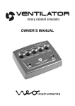
BEDIENUNGSANLEITUNG
OWNER’S MANUAL
INHALT
Seite
I EINLEITUNG
II. ANSCHLÜSSE UND EINSTELLUNGEN
III. BEDIENELEMENTE
IV. SWITCH MODES
V. TECHNISCHE DATEN
VI. SICHERHEITSHINWEISE
VII. GARANTIEBEDINGUNGEN
3
4
6
13
14
15
16
Die in dieser Bedienungsanleitung benutzten Markennamen
Hammond®, Leslie® sind geschützte Warenzeichen der
Hammond-Suzuki Corporation.
2
I. EINLEITUNG
Wir beglückwünschen Sie zum Kauf des Neo Instruments
VENTILATOR II. Um alle Möglichkeiten des Gerätes
ausschöpfen zu können, empfehlen wir Ihnen diese Anleitung
vollständig zu lesen und zum späteren Nachschlagen aufzubewahren. Auch die Verpackung sollte aufbewahrt werden, falls
ein späterer Versand des Geräts nötig wird.
Der VENTILATOR II ist ein digitales Effektgerät zur Simulation
eines Leslie 122 Rotorkabinetts bei Abnahme mit 3 Mikros
(Bass mono, Horn stereo). Es ist für Orgel und Gitarre
gleichermaßen geeignet und besitzt folgende herausragende
Merkmale:
- aufwändige Modeling Algorithmen, exakte Nachbildung des
Rotoreffekts eines 122er Leslies
- unabhängige Simulation von Bass- und Hochtonrotor
- genaue Reproduktion der mechanischen Eigenschaften
- Speakersimulation für authentischen 122er Frequenzgang
- Frequenzweiche 800Hz wie beim Original
- Rotorgeschwindigkeiten und Beschleunigung anpassbar
- Drive Sektion simuliert Verzerrung / Endstufensättigung des
Leslie Röhrenamps
- variabler Mikrofonabstand der virtuellen Mikrofone
- True Bypass Relaisschaltung
- Speaker Simulation für Wiedergabe über Gitarrenamp
abschaltbar
- Anschluss für Remote Fußschalter / Halfmoon Switch /
Expression Pedal
- Slow / Fast / Stop Funktion
- einfache, analoge Bedienung
- stabiles Stahlblechgehäuse, versenkte Knöpfe
3
II. ANSCHLÜSSE UND EINSTELLUNGEN
Der VENTILATOR II besitzt einen Stereo Eingang und einen
Stereo Ausgang. Mit dem Lo / Hi Schalter kann die
Eingangsempfindlichkeit an die Signalquelle angepasst
werden.
Der VENTILATOR II kann sowohl zwischen Instrument und
Verstärker bzw. Mischpult als auch an einem Einschleifweg
angeschlossen werden.
IN L, IN R / MONO
Eingangsbuchsen für ein Stereosignal (Orgel, Keyboard,
Gitarre). Für die Effekterzeugung wird allerdings nur das Signal
der IN R / MONO Buchse genutzt. Deshalb Mono Instrumente
unbedingt hier anschließen! Im Bypass werden beide Buchsen
stereo durchgeschleift.
LO / HI
Dieser Schalter schaltet die Empfindlichkeit der Inputs um. In
der Regel ist die Stellung Lo sowohl für Orgel / Keyboards als
auch Gitarre richtig. Nur für sehr leise Gitarren oder Keyboards
mit schwachem Output wird es nötig sein auf Hi umzuschalten.
Der Ausgangspegel bleibt in beiden Einstellungen konstant, da
das Ausgangssignal automatisch angepasst wird. Zur
Aussteuerungskontrolle dient die Overload LED.
Overload LED
Diese LED zeigt an, ob der maximale Eingangs – oder
Ausgangspegel der Schaltung erreicht ist. Um bestmöglichen
Rauschabstand und Auflösung des AD Wandlers zu
gewährleisten, sollte man das Eingangssignal soweit
aufdrehen, bis die LED bei Lautstärkespitzen anfängt zu
leuchten. Dann dreht man das Eingangssignal wieder soweit
leiser, bis die LED nicht mehr angeht. Nun ist die optimale
Aussteuerung erreicht.
4
OUT L, OUT R / MONO
Der VENTILATOR II besitzt einen Stereoausgang. Wenn das
Gerät an ein Mischpult angeschlossen wird, sollten die
Panoramaregler am Mischpult auf maximal links bzw. rechts
gedreht sein, um ein natürliches, räumliches Effektsignal zu
erzielen. Wird nur ein Monosignal benötigt (z.B. in einem
komplexen Mix, bei Verstärkung über Bühnenmonitor oder
Gitarrenverstärker) sollte nur der Ausgang R/MONO benutzt
werden.
REMOTE
An diese Buchse kann der optional erhältliche Ventilator
Remote bzw. Remote II Fußschalter, ein Handschalter vom
Typ Hammond CU-1 oder ein Expression Pedal (z.B. Yamaha
FC-7) angeschlossen werden.
12V DC
Zur Spannungsversorgung hier ausschließlich das mitgelieferte
Netzteil (12V DC, 0,5A) anschließen. Der VENTILATOR II
kann nicht mit Batterien betrieben werden.
UNBEDINGT BEACHTEN:
Um störungsfreien Betrieb zu gewährleisten sollten Sie alle
Anschlüsse vornehmen, bevor Sie das Netzteil anschließen.
5
III. BEDIENELEMENTE
Obwohl der VENTILATOR II ein digitales Gerät ist, ist die
Bedienung ähnlich einem analogen Effektgerät und daher
übersichtlich und leicht verständlich.
Um sich mit dem Gerät vertraut zu machen, empfiehlt sich als
Ausgangspunkt folgende Einstellung:
- HI / LO Gain Schalter auf Lo (nicht gedrückt)
- Fast Speed, Balance, Mix/Dist Lo, Mix/Dist Hi, Slow Speed,
Acceleration und Level auf Mittelstellung
- Drive auf Linksanschlag (aus)
- Für Orgel den MODE Parameter auf KEY (Rechtsanschlag),
für Gitarre auf GIT2 (Mittelstellung) stellen
- REMOTE auf Rechtsanschlag (aus)
III.1. TASTER, LEDs
BYPASS
Mit diesem Taster wird der Rotoreffekt an- und ausgeschaltet.
Im Bypassbetrieb erlischt die zugehörige rote LED (= Effekt
aus) und das Eingangssignal wird per Relais auf die Ausgänge
geschaltet (True Bypass).
SLOW / FAST
Dieser Taster schaltet die Geschwindigkeit des Rotoreffekts
abwechselnd auf langsam oder schnell. Bass- und
Hochtonrotor laufen wie beim Original unsynchronisiert in leicht
unterschiedlichen Geschwindigkeiten. Auch die Zeiten für
Beschleunigung / Abbremsen sind unterschiedlich, und zwar
für den Bassrotor deutlich länger.
6
STOP
Dieser Taster stoppt beide Rotoren komplett. Es wird immer
die gleiche Stopposition angefahren (Rotoren strahlen nach
vorn).
SPEED HI / LO
Die aktuelle Geschwindigkeit der Rotoren wird jeweils durch
eine LED (Bassrotor = LO / gelb, Hochtonrotor = HI / rot)
angezeigt.
III.2. POTENTIOMETER
Der Ventilator II besitzt fünf Regler um verschiedene
Parameter des Effekts zu steuern. Jeder Regler hat eine
Hauptfunktion (Beschriftung orange) und eine Zweitfunktion
(Beschriftung weiß). Um zwischen den Funktionsebenen zu
wechseln, den Bypass und Slow/Fast Taster zusammen
drücken. Die Aktivierung der Zweitfunktionen wird durch
Blinken der Speed LEDs angezeigt (2x pro Sekunde).
Die Taster Bypass, Stop und Slow/Fast sind dabei weiterhin
aktiv. Um zu den Hauptfunktionen zurückzukehren, nochmals
den Bypass und Slow/Fast Taster zusammen drücken. Die
Einstellungen der Zweitfunktionen werden gespeichert und
bleiben auch nach dem Ausschalten erhalten.
III.2.1 Potentiometer Haupfunktionen
FAST SPEED
Der Fast Speed Regler variiert die Geschwindigkeit für den
Bassrotor und Treblerotor wenn der Effekt auf FAST geschaltet
wird. Linksanschlag des Reglers bewirkt langsamere
Geschwindigkeiten, Rechtsanschlag entsprechend schnellere:
7
FAST
Bass 2,60Hz – 7,8Hz (6,5Hz)
Horn 2,72Hz – 8,16Hz (6,8Hz)
In Stellung 2.00 Uhr (Werte in Klammern) entsprechen die
Geschwindigkeiten einem durchschnittlichen 122er Leslie.
BALANCE
Das Balance Poti regelt das Lautstärkeverhältnis von Bass und
Hochtonrotor. Man kann es wie eine Art Equalizer benutzen,
um den Sound an verschiedene Eingangssignale oder den
musikalischen Kontext anzupassen. Auch eine Anpassung an
den Verstärker / Monitor kann damit erfolgen.
Durch Drehen nach rechts (von der Mittelstellung aus) werden
die Bassfrequenzen abgesenkt, bzw. durch Drehen Richtung
Linksanschlag entsprechend die höheren Frequenzen.
DRIVE
Dieser Regler aktiviert die interne Röhrensimulation des
VENTILATOR. Um die Drive Sektion bestmöglich zu nutzen,
sollte man zunächst den Input optimal aussteuern, wie unter
„Overload LED“ beschrieben. Dann wird das Volume Pedal
oder Poti am Instrument auf Maximum gebracht und der Drive
Regler am VENTILATOR auf die gewünschte maximale
Verzerrung eingestellt. Mit dem Volume Pedal oder Poti kann
die Verzerrung nun komfortabel und ausdrucksstark beim
Spielen zwischen clean und verzerrt geregelt werden.
Die Drive Sektion ist pegelkompensiert, d.h. der Ausgangspegel ändert sich kaum, wenn der Drive Regler weiter aufgedreht wird.
8
MIX / DIST LO
Dieser Regler kombiniert zwei Parameter. Der MIX Parameter
(erste Hälfte des Regelwegs) regelt die Modulationstiefe des
Bassrotors. Damit lässt sich der Effekt abschwächen.
Linksanschlag bedeutet kein Effekt vom Bassrotor.
Der Distance Parameter (zweite Hälfte des Regelwegs) regelt
den Abstand des virtuellen Bassrotor Mikrofons. Je weiter der
Regler im Uhrzeigersinn aufgedreht wird, umso näher steht
das Mikrofon am Leslie.
Bei Rechtsanschlag des Reglers enthält der Sound viel
Amplituden Modulation, vergleichbar einer Abnahme auf der
Bühne, wenn das Mikrofon ganz nah am Leslie steht. Dreht
man den MIX/DIST LO Regler in die Mitte, wird der Sound
diffuser mit weniger Amplituden Modulation, ähnlich einem
Setup im Studio, wenn das Mikrofon weiter weg steht.
MIX / DIST HI
Dieser Regler funktioniert ähnlich wie MIX / DIST LO, nur
diesmal für den Hochtonrotor. Der MIX Parameter (erste Hälfte
des Regelwegs) regelt das Verhältnis von Direktsignal und
Effektsignal des Hochtonrotors. Dadurch lässt sich der Effekt
dosiert einsetzen. Linksanschlag bedeutet kein Effekt vom
Hochtonrotor. Anstelle des Effekts ist das direkte
Eingangssignal zu hören (in stereo wenn beide Buchsen
genutzt werden).
Der Distance Parameter (zweite Hälfte des Regelwegs) regelt
den Abstand der virtuellen Hochtonrotor Mikrofone. Je weiter
der Regler im Uhrzeigersinn aufgedreht wird, umso näher
stehen die Mikrofone am Leslie.
Bei Rechtsanschlag des Reglers enthält der Sound viel
Amplituden Modulation, vergleichbar einer Abnahme auf der
Bühne, wenn die Mics ganz nah am Leslie stehen. Dreht man
den MIX/DIST HI Regler in die Mitte, wird der Sound diffuser
mit weniger Amplituden Modulation, ähnlich einem Setup im
Studio, wenn die Mikrofone weiter weg stehen.
9
III.2.2 Potentiometer Zweitfunktionen
SLOW SPEED
Der Slow Speed Regler variiert die Geschwindigkeit für den
Bassrotor und Treblerotor wenn der Effekt auf SLOW
geschaltet wird. Linksanschlag des Reglers bewirkt
langsamere Geschwindigkeiten, Rechtsanschlag entsprechend
schnellere:
SLOW
Bass 0,12Hz – 2,51Hz (0,76Hz)
Horn 0,13Hz – 2,62Hz (0,8Hz)
In Stellung 10.00 Uhr (Werte in Klammern) entsprechen die
Geschwindigkeiten einem durchschnittlichen 122er Leslie.
ACCELERATION
Hier wird die Zeit eingestellt, die beide Rotoren brauchen, um
von Slow auf Fast oder von Fast auf Slow zu wechseln.
Linksanschlag des Reglers bewirkt die kürzeste Beschleunigung bzw. Abbremsen, Rechtsanschlag entsprechend längere
Zeiten. In Stellung 1.00 Uhr des Reglers (Werte in Klammern)
entsprechen die Zeiten einem durchschnittlichen 122er
Kabinett. Die Zeit, welche die Rotoren brauchen um auf STOP
zu kommen ist fest eingestellt und wird vom Acceleration
Regler nicht beeinflusst.
SLOW > FAST
Bass 0,5sec – 4,2sec - 8sec – 8sec (5,5sec)
Horn 0,5sec – 0,5sec – 2sec - 8sec (1sec)
FAST > SLOW
Bass 0,8sec – 4,2sec - 8sec – 8sec (5,5sec)
Horn 0,8sec – 0,8sec – 3,2sec - 8sec (1,6sec)
10
MODE
Der Ventilator II bietet drei unterschiedliche Frequenzgänge für
die Verwendung mit Orgel oder Gitarre. Diese können über die
7 – 12 und 5 Uhr Stellung des Reglers gewählt werden.
Regler Mode
7.00
GIT1
Funktion
neutraler Frequenzgang für die Verwendung
an einem Gitarrenverstärker
12.00
GIT2
wie GIT1 aber betonte Mitten und Höhen
5.00
KEY
Simulation des Leslie 122 Frequenzgangs für
die Verwendung mit Orgel
Je nach verwendetem Verstärker / Lautsprecher und eigenen
Soundvorstellungen kann es jedoch auch bei Orgelsounds
Sinn machen die GIT Einstellungen zu benutzen, bzw. bei
Gitarrenverstärkern die KEY Einstellung.
REMOTE
Dieser Parameter bestimmt die Funktion der Remote Buchse.
Wird dort eine Ventilator remote / remote II oder ein Halfmoon
Schalter angeschlossen, können die Funktionen Stop / Slow /
Fast ferngesteuert werden. Wird ein Expression Pedal
angeschlossen kann damit stufenlos die Geschwindigkeit des
Effekts oder der Effekt Mix kontrolliert werden.
Die Reglerstellungen um die verschiedenen Modes
auszuwählen sind 7 – 9 – 12 –3 – 5 Uhr.
Regler Mode Funktion
7.00
Switch1 Stop/Slow/Fast Fernsteuerung durch Taster
(Ventilator remote II)
Ring - Masse = Slow / Fast,
Tip - Masse = Stop
11
9.00
Switch2 Stop/Slow/Fast Fernsteuerung durch
Schalter (Ventilator remote,CU-1)
12.00
Speed
Geschwindigkeitssteuerung durch ein
Expression Pedal. Der Regelbereich wird
eingestellt durch den Slow Speed Regler (=
Pedal minimum) und den Fast Speed Regler
(= Pedal maximum). Wenn Slow Speed auf
Linksanschlag steht, wird bei Pedal Minimum
auf Stop geschaltet. Die STOP und
SLOW/FAST Taster haben in diesem Mode
keine Funktion.
3.00
Mix
Steuerung der Parameter MIX/DIST LO und
MIX/DIST HI durch ein Expression Pedal.
Der verfügbare Regelbereich ist 0 bis zum
eingestellten Wert der beiden MIX / DIST
Regler.
5.00
Off
Schaltet die Remote Buchse ab.
LEVEL
Mit diesem Parameter kann der Ausgangspegel des
Ventilator II angepasst werden. In 12.00 Uhr Stellung des Potis
ist das Effektsignal in etwa gleich laut mit dem Bypass Signal.
12
IV. SWITCH MODES
Für das Verhalten der beiden Taster SLOW/FAST und STOP
stellt der VENTILATOR II sechs verschiedene Modes zur
Verfügung. Um diese auszuwählen hält man beim Einschalten
des Geräts die SLOW/FAST Taste für 3 Sekunden gedrückt.
Dadurch gelangt man in eine Edit Routine. Nun kann man mit
dem STOP Taster den vorhergehenden Mode aus der Liste
auswählen oder mit dem SLOW/FAST Taster den
nachfolgenden. Die beiden Speed LEDs zeigen den jeweils
aktiven Mode an:
Lo LED blinkt 1x/sec, Hi LED aus >>>
Mode1
Lo LED blinkt 2x/sec, Hi LED aus >>>
Mode2
Lo LED blinkt 3x/sec, Hi LED aus >>>
Mode3
Hi LED blinkt 1x/sec, Lo LED aus >>>
Mode4
Hi LED blinkt 2x/sec, Lo LED aus >>>
Mode5
Hi LED blinkt 3x/sec, Lo LED aus >>>
Mode6
Nach der Auswahl drückt man STOP und SLOW/FAST
zusammen für 2 Sekunden um die Einstellung zu speichern
und zum normalen Betriebsmodus zurückzukehren.
Wenn SWITCH1 für den Parameter REMOTE gewählt wurde,
gelten die hier gemachten Einstellungen auch für den externen
Fußschalter.
MODE 1 (“122 style”) Beide Taster haben “rastende”
Funktion. Für erneutes Schalten muß der Taster zuerst
losgelassen und dann wieder gedrückt werden. Die FAST
Einstellung hat Priorität vor STOP.
MODE 2 (“760 style”) Beide Taster haben “rastende”
Funktion. STOP hat Priorität vor SLOW / FAST. Man kann
jedoch während STOP mit dem SLOW/FAST Taster eine
„Voreinstellung“ vornehmen, die dann aktiv wird, wenn der
STOP Taster erneut gedrückt wird.
MODE3 Beide Taster haben “rastende” Funktion. STOP hat
Priorität vor SLOW / FAST. Wenn SLOW/FAST nach STOP
gedrückt wird, wird immer SLOW ausgeführt.
13
MODE 4 Beide Taster arbeiten momentan. Die Funktion wird
nur ausgeführt solange der Taster gehalten wird. Die
Grundeinstellung, solange keinTaster gedrückt ist, ist SLOW.
MODE 5 Dieser Mode ist ähnlich dem Mode1, aber hier
arbeitet der SLOW/FAST Taster momentan. Der STOP Taster
hat dagegen „rastende“ Funktion. FAST hat Priorität vor STOP.
MODE 6 Dieser Mode ist ähnlich dem Mode2, aber hier
arbeitet der STOP Taster momentan. Der SLOW/FAST Taster
hat dagegen „rastende“ Funktion. STOP hat Priorität vor
SLOW/FAST.
V. TECHNISCHE DATEN
Signalverarbeitung
Analog Digital Wandlung
Digital Analog Wandlung
Rauschpegel
Eingangsempfindlichkeit
Eingangswiderstand
Ausgangspegel
Ausgangswiderstand
Empfohlener Anschlusswert
Gewicht
Abmessungen (B x T x H)
Netzspannung
Stromverbrauch
Anschlüsse
Optional
32 Bit SHARC DSP
48khz, 24 Bit
48khz, 24 Bit
-80 dBA
-10 dBV (Hi), 0 dBV (Lo)
1MOhm
+6 dBV
100 Ohm
10 KOhm oder mehr
1,1kg (ohne Netzteil)
160 x 143 x 55mm
100V-240V, 47Hz-63Hz
max.300mA
Eingang L
Eingang R / Mono
Ausgang L
Ausgang R / Mono
Remote Eingang
Ventilator Remote (II)
Halfmoon Switch CU-1
Änderungen auch ohne Vorankündigung vorbehalten.
14
VI. SICHERHEITSHINWEISE
- Gerät nicht öffnen! Es befinden sich keine vom Benutzer zu
wartenden Teile im Innern des Geräts.
- Zur Reinigung ausschließlich ein trockenes Tuch oder einen
Pinsel verwenden.
- Gerät nicht in der Nähe von Wasser betreiben.
- Zur Vermeidung von Funktionsstörungen oder sogar
elektrischen Schlägen das Gerät und insbesondere das
Netzteil nicht Regen oder Feuchtigkeit aussetzen.
- Nicht in der Nähe von Heizungen und Wärmequellen
betreiben.
- Gerät nicht direkter Sonneneinstrahlung aussetzen.
- Nur mit dem mitgelieferten Netzteil und nur mit den
angegebenen Netzspannungen betreiben.
- Gerät keinen Erschütterungen und harten Stößen aussetzen.
- Zum Schutz des Gerätes bei Gewitter oder wenn es längere
Zeit nicht beaufsichtigt wird, sollte der Netzstecker gezogen
werden.
- Netzstecker niemals mit nassen Händen anfassen.
- Beim Ausstecken des Netzteils immer am Stecker und nicht
am Kabel fassen.
Bestimmungsgemäße Verwendung
Dieses Gerät ist ausschließlich zur Erzeugung von
niederfrequenten Audiosignalen zu tontechnischen Zwecken
bestimmt. Eine weitergehende Verwendung ist nicht zulässig
und schließt Gewährleistungsansprüche gegenüber
Neo Instruments aus.
15
VII. GARANTIEBEDINGUNGEN
Neo Instruments gewährt eine Garantie von 12 Monaten ab Kaufdatum
für alle nachweisbaren Material- und Fertigungsfehler. Die gesetzlichen
Gewährleistungsansprüche werden hiervon nicht berührt.
Der Garantieanspruch erstreckt sich auf die Beseitigung festgestellter
Mängel durch Reparatur oder Ersatz der defekten Teile. Weitergehende Ansprüche, so insbesondere auf Wandlung oder Minderung,
können erst nach erfolgloser Nachbesserung bzw. Ersatzlieferung
geltend gemacht werden.
Die Garantieleistung bezieht sich nicht auf Transportschäden, auch
nicht auf Schäden durch Nichtbeachtung der Bedienungsanleitung,
und fehlerhafter oder nachlässiger Behandlung des Gerätes.
Außerdem fallen nicht unter die Garantiebestimmungen Schäden oder
Fehler durch höhere Gewalt (Blitzschlag, Hochwasser, usw.) oder
sonstige äußere Einflüsse, sowie mechanische Beschädigungen oder
Mängel, die nicht auf Materialverarbeitungsfehler zurückzuführen sind.
Sollten Defekte innerhalb der Garantiezeit auftreten, kontaktieren Sie
uns bitte unter folgender Adresse:
NEO Instruments
Flemingstrasse 20-22
D-36041 Fulda
+49 (0)661-9619805
[email protected]
www.neo-instruments.de
16
17
CONTENTS
Page
I WELCOME
II. CONNECTIONS AND SETTINGS
III. CONTROLS
IV. SWITCH MODES
V. SPECIFICATIONS
VI. SAFETY GUIDELINES
VII. WARRANTY TERMS
19
20
22
28
30
31
32
The brand names Hammond® and Leslie® used in this
operating manual are protected trademarks of HammondSuzuki Corporation.
18
I. WELCOME
Congratulations and thank you for purchasing Neo Instruments’
VENTILATOR II. If you wish to make the most of this device’s
many features and full sound-shaping potential, we
recommend that you read this manual and keep it for later
reference. Be sure to also save the packaging just in case you
have to send it at a later date.
VENTILATOR II is a digital FX device that simulates a model
122 Leslie rotary speaker cabinet mic’ed up with a stereo pair
on top for the treble horn and a single mono mic below for the
bass woofer. Designed to deliver great results with organ and
guitar, its outstanding features include:
- Sophisticated modeling algorithms and a faithful replication of
the model 122 Leslie’s rotary effect
- Independent emulations of bass and treble rotors
- Faithful replication of the original’s mechanical properties
- Speaker simulation emulating the 122’s frequency response
- Same 800Hz crossover as the original
- Adjustable rotary speed and acceleration
- Drive section that simulates distortion / power tube saturation
in the Leslie’s amp
- Variable placement of virtual microphones
- Relay-equipped true bypass circuit
- Speaker simulation may be switched off for guitar amps
- Port for a remote footswitch / half-moon switch / expression
pedal
- Slow / Fast / Stop switching
- Rugged sheet metal chassis and recessed buttons
- Simple, straightforward analog handling
19
II. CONNECTIONS AND SETTINGS
VENTILATOR II comes with a stereo input and a stereo output.
The Lo / Hi switch matches input gain to the signal source. You
can insert VENTILATOR II between your instrument and amp
or mixing console as well as into an FX loop.
IN L, IN R / MONO
This jacks accept stereo organ, keyboard, and guitar signals.
However for the rotary effect only the IN R / MONO jack is
used. Connect mono instruments here. In Bypass mode both
jacks are routed to the outputs in stereo.
LO / HI
This switch adjusts input gain. The Lo position works for most
organs, keyboards, and guitars. Only very low-output guitars
and keyboards require you to switch over to Hi. The output
signal is automatically compensated to ensure a constant level
at both settings. The Overload LED serves as a level meter.
Overload LED
This LED lights up to indicate the input or output signal level
has reached the circuit’s threshold. For the best possible
signal-to-noise ratio and AD converter resolution, turn up the
input signal until the LED just begins lighting up at signal
peaks. Then back the input signal off again until the LED no
longer lights up. That’s the optimum level for this device.
OUT L, OUT R / MONO
VENTILATOR II provides a stereo output. If you connect the
device to a mixing console, turn the mixer’s panorama knobs to
the far left and right to achieve a realistic-sounding spatial
effect. If you need just a mono signal – say, in an elaborate
composite mix or when using a stage monitor or guitar amp –
tap it by plugging into the R/MONO output only.
20
REMOTE
This jack accepts the optionally available Ventilator Remote /
Remote II footswitches, a Hammond CU-1 type Halfmoon or a
YAMAHA FC-7 type expression pedal
12V DC
Connect the included AC adapter (12V DC, 0.5A) only; do not
use any other wall-wart or power supply. VENTILATOR II
cannot be powered by batteries.
HEADS UP:
To ensure flawless operation, always connect all other cords
before you plug in the AC adapter.
21
III. CONTROLS
Although VENTILATOR II is a digital device, it handles much
like an analog effect, with similar convenience and ease of use.
A good way to get to know the device is to start with this setup:
- Set HI / LO GAIN switch to Lo (switch is out)
- Set Fast Speed, Balance, Mix/Dist Lo, Mix/Dist Hi, Slow
Speed, Acceleration and Level to the 12 o’clock position.
- Turn Drive to the far left (off).
- Set the MODE parameter to KEY (far right position) for an
organ, and to GIT2 (12 o’clock position) for guitar.
- Turn the Remote control off by switching to secondary
parameter mode and setting the REMOTE knob to the far right
position.
III.1. SWITCHES / LEDs
BYPASS
This stomp-switch turns the rotary effect on and off. Its red LED
lights up when the effect is actice. In Bypass the input signal is
relayed to the outputs via a true bypass circuit.
SLOW / FAST
This stomp-switch determines the speed of the rotary effect by
switching between slow and fast. As on the original, the bass
and treble rotors run out of sync at slightly different speeds.
Acceleration and deceleration times also differ, with the bass
rotor taking much longer to speed up and slow down.
STOP
This switch stops the rotors completely. The Stop position is
always with the rotors facing forward.
22
SPEED LO / HI
One LED each indicates the respective rotor’s current speed
(bass rotor = LO / yellow; treble rotor = HI / red).
III.2. POTS
Ventilator II features five knobs, each serving two functions. In
primary mode the knobs control the parameters labeled in
orange. In secondary mode the knobs control the parameters
labeled in white. The secondary functions are accessed by
pressing the Bypass and Slow/Fast switch simultaneously.
When in secondary mode, the Speed LEDs will blink two times
per second. The Bypass, Stop and Slow/Fast switch remain
active. To return to primary mode just press the Bypass and
Slow/Fast switch together again. Secondary parameters are
stored to memory and are restored on next power up.
III.2.1 Pots Primary Functions
FAST SPEED
The Fast Speed knob adjusts the bass and treble rotors’
speeds while the unit is in FAST mode. Twist the knob to the
far left for slower speeds and to the far right for faster speeds:
FAST
Bass 2,60Hz – 7,8Hz (6,5Hz)
Horn 2,72Hz – 8,16Hz (6,8Hz)
The 2 o’clock position yield the values shown in brackets,
which correspond to the speeds of an average 122 model
Leslie.
23
BALANCE
The Balance knob adjusts the relative volumes of the bass and
treble speakers. Use it much like you would an equalizer,
adapting the unit’s sound to suit different types of input signals
and the musical context, amp, or monitor.
Twisting it to the right from the 12 o’clock position cuts low
frequencies; turning it to the left cuts higher frequencies.
DRIVE
This knob activates VENTILATOR II’s on-board tube simulator.
To make the most of the Drive section, ensure you dial in the
optimum input level as described in the section above entitled
Overload LED. Then set the instrument’s volume to the
maximum level and twist VENTILATOR II’s Drive knob to dial
in the maximum distortion level. This lets you ride the
instrument’s volume pedal or knob to control the amount of
saturation, which is a convenient and musically expressive way
of modulating between clean and distorted sounds on the fly.
The Drive section is level-compensated; that is, the output level
does not change much as you turn up the Drive knob.
MIX / DIST LO
This controls the mix of the lower rotor in the signal as well as
the distance of the virtual mic from the rotor. The first half of
the travel (from all the way counter-clockwise to center)
determines the mix. At 7 o’clock (all the way counter-clockwise)
there is no lower rotor simulation in the mix. Note this does not
remove the bass content from the signal; it simply removes the
rotary effect. You can use this to emulate the classic “Memphis
style” Leslie sound. The “Memphis style” on a real Leslie is
24
achieved by unplugging the motors on the lower rotor, so that
only the upper rotor spins.
From center to 5 o’clock (all the way clockwise), the knob
adjusts the distance of the virtual mic from the lower rotor. This
is handy for decreasing the amount of AM (amplitude
modulation) in the signal. Pulling the mic further back
decreases the “wub wub wub” effect that can be distracting,
especially when you’re playing left hand and/or pedal bass.
MIX / DIST HI
As with the MIX / DIST LO knob, this controls the mix of the
upper rotor in the signal as well as the distance of the virtual
mics from the rotor. The first half of the travel (from all the way
counter-clockwise to center) determines the mix. At 7 o’clock
(all the way counter-clockwise) there is no upper rotor
simulation in the mix. Instead you’ll hear the direct input signal
(in stereo if both jacks are used).
From center to 5 o’clock (all the way clockwise), the knob
adjusts the distance of the virtual mics from the upper rotor.
III.2.2 Pots Secondary Functions
SLOW SPEED
The Slow Speed knob adjusts the bass and treble rotors’
speeds while the unit is in SLOW mode. Twist the knob to the
far left for slower speeds and to the far right for faster speeds:
SLOW
Bass 0,12Hz – 2,51Hz (0,76Hz)
Horn 0,13Hz – 2,62Hz (0,8Hz)
25
The 10 o’clock position yield the values shown in brackets,
which correspond to the speeds of an average 122 model
Leslie.
ACCELERATION
This knob adjusts the amount of time it takes both rotors to go
from slow to fast and from fast to slow. Set the knob to the far
left for the fastest acceleration and deceleration time. Twist it to
the right and the effect will be slower to speed up and slow
down. The 1 o’clock positions yield the values shown in
brackets, which correspond to the speeds of an average 122
model Leslie.
SLOW > FAST
Bass 0,5sec – 4,2sec - 8sec – 8sec (5,5sec)
Horn 0,5sec – 0,5sec – 2sec - 8sec (1sec)
FAST > SLOW
Bass 0,8sec – 4,2sec - 8sec – 8sec (5,5sec)
Horn 0,8sec – 0,8sec – 3,2sec - 8sec (1,6sec)
MODE
The VENTILATOR II features three different frequency
responses for the use with guitar or organ. They are accessed
via the 7 – 12 –5 o’clock position of the MODE knob.
Pos
7.00
Mode
GIT1
Functionality
neutral response for use with a guitar amp
12.00
GIT2
similar to GIT1 but with accentuated mids
and highs
5.00
KEY
Simulation of the Leslie 122 response for use
with organ
26
Depending on the speaker, amp, and your taste in tone, the
GIT settings can yield interesting results in combination with
organ sounds, as can the KEY setting with guitar amps.
REMOTE
This parameter determines the function of the remote control
jack socket. It is possible to connect a volume pedal (YAMAHA
FC-7 or similar), a passive remote switch (unlatched), the
VENTILATOR remote / remote II or a CU-1 Halfmoon switch.
The corresponding pot positions for selecting the modes are
7 - 9 - 12 - 3 - 5 o’clock.
Pos
7.00
Mode Functionality
Switch1 Stop/Slow/Fast control by external unlatched
switches (Ventilator remote II)
Ring to Sleeve = Slow / Fast,
Tip to Sleeve = Stop
9.00
Switch2 Stop/Slow/Fast control by external latching
switches (Ventilator remote,CU-1)
12.00
Speed
SPEED is continously controllable by an
expression pedal. Available Speed range is
set by the SLOW SPEED pot (=pedal
minimum) and the FAST SPEED pot (= pedal
maximum). If Slow Speed is set to zero, the
Pedal minimum activates Stop. Slow/Fast
and Stop Switches are not active in this
mode.
3.00
Mix
Parameters MIX/DIST LO and MIX/DIST HI
are continously controllable by an expression
pedal. Available range is zero up to the value
set by the MIX/DIST knobs.
27
5.00
Off
Turns remote control off.
LEVEL
Adjusts the overall output level of the Ventilator II. 12 o’clock is
the default position with the effect signal’s level roughly equal
to the bypass signal.
IV. SWITCH MODES
If the SLOW/FAST switch is pressed and held for 3 seconds on
power up, the Ventilator enters an edit routine enabling the
user to adjust the switch behaviour of the STOP and SLOW /
FAST switch.There are 6 modes (see below) that can be
stepped through by pressing the Stop (decrement) or
Slow/Fast switch (increment): The Lo and Hi Leds indicate the
current setting:
Lo LED blinking 1x/sec, Hi LED off
Lo LED blinking 2x/sec, Hi LED off
Lo LED blinking 3x/sec, Hi LED off
Hi LED blinking 1x/sec, Lo LED off
Hi LED blinking 2x/sec, Lo LED off
Hi LED blinking 3x/sec, Lo LED off
>>>
>>>
>>>
>>>
>>>
>>>
Mode1
Mode2
Mode3
Mode4
Mode5
Mode6
Pressing Stop and Slow/Fast together for 2 seconds stores the
setting and leaves the edit routine. When SWITCH1 is selected
via the Remote parameter, the Switch Mode setting also
affects the external remote’s switch behaviour.
28
MODE 1 (“122 style”) Both switches are latching types; press
once to change speed, press again to go back to the previous
setting. Selecting FAST speed overrides any setting on the
STOP switch.
MODE 2 (“760 style”) Both switches are latching types. The
STOP mode overrides any setting on the SLOW / FAST
switch. You can however “preset” a speed with the SLOW /
FAST switch which becomes active when leaving Stop mode
by pressing STOP again.
MODE3 Both switches are latching types; STOP overrides any
setting of the SLOW / FAST switch. If SLOW / FAST is pressed
from STOP, SLOW will always be selected.
MODE 4 Both switches are momentary (unlatched) types
(press and hold). Pressing the STOP button causes the
Ventilator to STOP until the switch is released. Pressing the
FAST / SLOW button causes the Ventilator to run at FAST
speed until the switch is released. The default mode (when
neither switch is pressed) is SLOW.
MODE 5 This setting is similar to MODE 1, except that the
SLOW / FAST switch acts in a momentary (unlatched) manner
(press and hold). STOP is a latching switch (press and
release). FAST mode overrides any setting on the STOP
switch.
MODE 6 This setting is similar to MODE 2, except that the
STOP switch acts in a momentary (unlatched) manner (press
and hold). SLOW / FAST is a latching switch (press and
release). STOP mode overrides any setting on the SLOW /
FAST switch.
29
V. SPECIFICATIONS
Signal processing
Analog Digital Conversion
Digital Analog Conversion
Noise Level
Input Sensivity
Input Impedance
Output Level
Output Impedance
Recommended Load Impedance
Weight
Dimensions (W x D x H)
Mains Voltage
Current Draw
Connectors
Options
Subject to change without notice.
30
32 Bit SHARC DSP
48khz, 24 Bit
48khz, 24 Bit
-80 dBA
-10 dBV (Hi), 0 dBV (Lo)
1MOhm
+6 dBV
100 Ohms
10 KOhms or more
1.1kg / 2 lbs 7 oz (without
Power Supply)
160 x 143 x 55mm
100V-240V, 47Hz-63Hz
< 300mA
Input L
Input R / Mono
Output L
Output R / Mono
Remote Input
Ventilator Remote (II)
Halfmoon Switch CU-1
VI. SAFETY GUIDELINES
- Do not open the device – no user serviceable parts inside!
- Clean with a dry cloth or brush only.
- Do not operate this device near water.
- To avoid malfunctions and electric shock, do not expose the
device or its AC adapter to rain or moisture.
- Do not operate the unit near radiators or other heat sources.
- Do not expose the device to direct sunlight.
- Power the device with the included AC adapter and the
indicated mains voltages only.
- Do not expose the device to vibrations and hard shocks.
- Pull the power plug when the device is unsupervised for
longer periods and to protect it from the effects of lightning.
- Never touch the power cable’s plugs with wet hands.
- Always disconnect the device by pulling the plug, and not the
cord.
Intended Use
This device is intended exclusively for generating lowfrequency audio signals used for sound-engineering purposes.
Any other use is not permitted and automatically invalidates the
warranty extended by Neo Instruments.
31
VII. WARRANTY TERMS
Neo Instruments extends a warranty covering all verifiable defects in
material and workmanship for a period of 12 months from the date of
original purchase. Statutory warranty rights remain unaffected hereby.
The warranty covers the remedying of manifest defects by replacing or
repairing defective parts. Any other claims, in particular those for a
reduction in price or cancellation of contract, may only be made after
an attempt to rectify the defect or deliver a replacement has failed.
The warranty does not cover damage incurred during transit, as well as
damage caused by non-compliance with the operating manual and
improper or negligent handling of the device. Beyond that, the warranty
does not cover defects or damage caused by acts of God (including
but not limited to lightning, floods, etc.) or other external influences, as
well as mechanical damage or flaws that are not attributable to
manufacturing defects.
If defects occur during the warranty period, please contact us at the
following address:
NEO Instruments
Flemingstrasse 20-22
D-36041 Fulda
+49 (0)661-9619805
[email protected]
www.neo-instruments.de
32