1
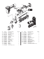
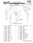
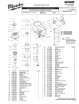
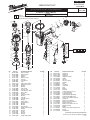
PAGE 1 OF 2
BULLETIN NO.
SERVICE PARTS LIST
54-43-0050
REVISED BULLETIN
SPECIFY CATALOG NO. AND SERIAL NO. WHEN ORDERING PARTS
STRAIGHT FINISH NAILER
00
CATALOG NO. 7145-21
EXAMPLE:
0 Component Parts (Small #) Are Included
When Ordering The Assembly (Large #).
STARTING
SERIAL NUMBER
WIRING INSTRUCTION
A89A
47
48
46
2
3
52
51
50
49
45
44
15
4
5
6
16
1
24
42
DATE
Mar. 2006
53
43
17
82
18
37
36
9
10
11
12
7
8
13
85 41
86
40
93
88
20
35
92
87
19
91
89
90
94
21
95
14
25
26
27
28
29
30
31
32
33
97
25 26 27 28 29 30
31 32 33 34 35 43
34
39
38
22
23
FIG. PART NO. 1 05-84-0845
2 05-84-0805
3 31-05-0400
4 43-31-0355
5 45-88-1720
6 42-92-1420
7 45-06-0925
8 45-06-0940
9 40-50-3110
10 44-62-0250
11 34-40-3240
12 34-40-3175
13 42-76-0800
14 45-06-0910
15 44-90-0700
16 44-90-0820
17 34-40-3220
18 43-12-0250
19 34-40-3270
20 42-98-0350
21 44-90-0800
22 42-38-0300
23 43-56-0895
24 42-38-0360
25 34-40-3295
26 34-40-3300
27 42-52-0410
28 44-70-0250
29 34-40-3285
30 34-40-3280
31 40-50-3195
32 44-70-0255
33 34-40-3290
34 43-64-0150
DESCRIPTION OF PART Bolt Assembly
Deflector Bolt
Deflector
Muffler
Deflector Pad
Top Cap
Seal Gasket
Seal
Upper Valve Spring Head Valve Piston O-Ring
O-Ring
Valve Collar
Top Cap Seal
Cylinder Press Ring
Piston Ring
O-Ring
Driver Assembly
O-Ring
Cylinder
Cylinder Spacer
Bumper
Driver Guide Bumper Band
O-Ring
O-Ring
Plunger Cap
Trigger Valve Plunger
O-Ring
O-Ring
Spring
Plunger
O-Ring
Trigger Valve Head
NO. REQ.
4
1
1
1
1
1
1
1
1
1
1
1
1
1
1
1
1
1
1
1
1
1
1
1
1
1
1
1
2
1
1
1
2
1
FIG. 35
36
37
38
39
40
41
42
43
44
45
46
47
48
49
50
51
52
53
85
86
87
88
89
90
91
92
93
94
95
PART NO. 06-65-1465
06-65-1440
06-65-1480
31-92-0200
40-50-3160
44-10-0650
40-50-3095
44-86-0710
44-90-0825
28-50-0800
44-90-0785
43-31-0370
34-40-3250
42-92-1350
05-84-0950
40-50-3180
45-08-0460
42-70-0400
05-83-0525
43-56-0865
06-65-1405
40-50-3050
42-36-2050
43-98-0755
42-92-1495
44-94-0570
34-40-3310
42-36-1995
44-90-0770
42-38-0320
DESCRIPTION OF PART Spring Pin
Spring Pin
Spring Pin
Trigger Assembly
Spring
Selector
Selector Spring
Retainer
Ring
Tool Body
Snap Ring
Filter
O-Ring
End Cap Socket Head Hex Screw
Positioning Spring Positioning Shaft
Spring Retainer (Belt Clip)
Round Head Phillips Bolt
Work Contact Element Guide
Spring Pin
Work Contact Spring
Work Contact Assembly B
Adjustment Knob
Work Contact Element Cover
Adjustment Rod O-Ring
Work Contact Element Bracket A E-Ring
No-Mar Pad
NO. REQ.
1
2
1
1
1
1
1
1
1
1
1
1
1
1
1
1
1
1
2
1
1
1
1
1
1
1
1
1
1
1
MILWAUKEE ELECTRIC TOOL CORPORATION
13135 W. Lisbon Road, Brookfield, WI 53005
Drwg.2
83
82
82
81
98
75
79
80
65
66
67
64
75 76 77
78 79 80
83
78
61
62
84
74
76
77
63
96
70
68
69
71
83
55
106
54
72
56
58
57
104
73
59
60
FIG. PART NO. 54 05-84-0995
55 42-92-1395
56 42-92-1380
57 06-65-1455
58 45-88-1705
59 44-20-0850
60 06-65-1450
61 44-60-1855
62 43-56-0855
63 44-90-0760
64 05-83-0515
65 44-86-0705
66 44-66-1305
67 40-50-3030
68 31-10-0520
69 40-50-3140
70 43-40-0455
71 44-90-0765
72 45-88-1740
73 05-84-0900
DESCRIPTION OF PART Bolt Assembly
Driver Guide Cover B
Driver Guide Cover A
Spring Pin
Pusher Cushion Lock Handle Assembly
Spring Pin
Fixed Pin
Driver Guide E-Ring
Half Round Hex Bolt Retainer Ring
Positional Plate Positioning Spring Bracket
Spring
Magazine A
E-Ring
Flat Washer
Socket Head Hex Screw
NO. REQ.
2
1
1
1
1
1
1
1
1
1
1
1
1
1
1
1
1
1
1
1
FIG. 74
75
76
77
78
79
80
81
82
83
84
96
97
98
104
106
PART NO. 44-81-0050
42-92-1475
05-84-0940
43-72-0350
42-28-0350
40-50-3150
42-42-0600
43-40-0485
05-84-0905
05-59-2025
42-92-1445
05-78-0810
31-94-0110
45-24-0030
12-98-0320
10-20-3310
14-70-0180
14-70-0185
DESCRIPTION OF PART Steel Channel
Protecting Hood Cover Flat Head Hex Bolt
Pusher
Anchor Block Spring
Pusher Button Magazine B
Socket Head Hex Screw
Lock Nut
Magazine End Cover Tap Bolt (M3 x5 )
Trigger Valve Assembly
Magazine Pusher Assembly
Service Nameplate
Warning Label
Overhaul Kit (Not Shown)
Driver Maintenance Kit (Not Shown)
NO. REQ.
1
1
1
1
1
1
1
1
1
3
1
2
1
1
1
1
BULLETIN NO. 54-43-0050 Mar. 2006
PAGE 2 OF 2
Disassembly:
2, 3, 4, 5, 6
Remove hex bolt (2), deflector (3), muffler (4) and deflector pad (5) from top cap (6). 4 mm hex key required.
1, 6
Remove hex bolts (1) to remove top cap (6). 4 mm hex key required.
7, 8, 9, 10, 11, 12, 13
Remove valve assembly (7, 8, 9, 10, 11, 12, and 13) out of the top cap using a 1/8 in. (3.18 mm) punch. Gently push
punch through several different holes in the top of the cap to remove assembly evenly.
15, 20, 44
Remove press ring (15) from the top of cylinder (20) before removing cylinder assembly from tool body (44).
20, 44
Remove cylinder assembly (20) using two pair of needle-nose pliers. Gently grasp the ribs of the cylinder (on opposing
sides) to pull the cylinder from tool body (44).
64, 69, 70, 73, 81, 82, 94
Remove magazine assembly (70 and 81) as an assembly, by removing screw(s) (73, 82, and 64).
Note: When removing magazine assembly (70 and 81) hold Pusher Assembly (98) stationary to restrict movement of
spring (69).
37, 38, 39, 40, 41,42, 43,
44, 97
Remove trigger valve assembly (97) from tool body (44) by placing a 3/32 in. (2.5mm) punch inside half-moon slot of
retainer (42) and gently tapping shaft of selector (40).Remove spring (41), retainer (42) and ring (43). Remove spring, (39)
and trigger (38) from tool body and push pins (36 and 37) out of tool body (44) just far enough to remove valve assembly
using service fixture 61-60-0005. Trigger valve assembly (97) can be gently pushed out of the tool body from the inside
handle area of the tool body using a flat blade screwdriver.
Reassembly:
36, 37, 44, 97
Reinstall trigger valve assembly (97) into tool body (44) by aligning the grooves in the valve assembly with the two holes
for spring pins (36 and 37). Drive spring pins into tool body until they are flush with the casting surface using service
fixture number 61-60-0005.
38, 39, 40, 41, 42, 43, 44, Reinstall selection lever assembly (40, 41, 42, 43,) and trigger assembly (38 and 39) by doing the following.
97
• Place spring (41) onto shaft of selection lever (40).
• Position spring (39) and trigger (38) over plunger of trigger valve assembly (97).
• Insert selection lever assembly (40 and 41) into tool body (44) and align half-moon slot of retainer (42) with halfmoon shaft of selection lever (40) and snap retainer assembly (42 and 43) onto the shaft.
18, 23, 44
Install flat side of driver guide (23) towards front of tool body (44).
Note: Center opening of driver guide (23) has a flat side and one with a slight offset to accommodate / help align blade
of driver assembly (18) in the assembly
20, 21
Reinstall cylinder ring (21) onto cylinder (20) with flanged end facing the top of cylinder (20) when installed.
16, 17, 18, 19, 20, 21, 22, Assemble driver assembly (16, 17, and 18) and install it into cylinder assembly (19, 20, 21, and 22. Install assembled
23, 44
components into tool body (44). Note: Orientation of driver assembly (18) must match orientation of driver guide (23).
6, 15, 20
Reinstall press ring (15) onto top of cylinder (20) with wide edge facing toward top cap (6).
6, 24
Reinstall bumper band (24) into slot on top cap (6).
6, 7, 8, 9, 10, 11, 12, 13
Reinstall spring (9) into internal bore of top cap (6) and snap preassembled head valve assembly (7-13) into top cap.
1, 6, 44
Reinstall top cap assembly (6) onto tool body (44) using hex bolts (1).
Note: To properly seat top cap, tighten the screws at alternating corners a few turns at a time until all screws are
secure.
44, 64, 70, 72, 73, 74, Reinstall magazine assembly (70 and 81) onto tool body (44) by securing screw/washer (72 and 73) and two screws (64
81,82
and 82).
Note: Make sure magazine channel (74) is aligned properly at the front and rear of the magazine assembly.
46, 48
Install smooth side of filter (46) toward end cap (48).
Apply Blue Loctite® 242 to fasteners (1), (2), (54) (64), (73) and (93), if removed during disassembly.
Lubrication:
Type I Grease 49-08-7100
Clean all parts with a dry clean cloth.
6, 7, 8, 9, 10, 11, 12, 13
Place a thin coating of grease into internal bore of top cap (6), coat parts (7 – 13) and reassemble in order shown.
16, 17, 18
Coat o-ring (17) and piston ring (16) prior to installing into groove of driver assembly (18).
19, 20, 21
Coat cylinder o-ring (19), and cylinder ring (21) prior to installing onto cylinder (20).
25, 26 27, 28, 29, 30, 31,
32, 33, 34, 35
Coat all parts of the trigger valve assembly (25-35) if being replaced individually. Components cleaned in any type of
solvent or water solution will require new lubrication.
Note: A new trigger valve assembly will be pre-lubricated and will not require any additional lubrication.