1
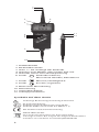
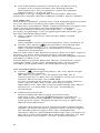
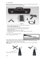
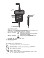
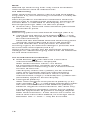
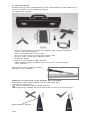
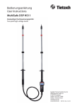
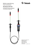
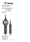
Bedienungsanleitung User Instructions ΩMegaSafe EP 4 / EP 4Ex Rudolph Tietzsch GmbH & Co. KG Willringhauser Str. 18 D-58256 Ennepetal Telefon +49 2333-75989 Telefax +49 2333-75257 E-Mail [email protected] www.tietzsch.de EP 4_BA_07-11 1 2 3 4 5 11 6 7 8 12 9 10 1 Prüfelektrode 2 Elektrodenschutz 3 LEDs +/- für Anzeige der Polarität 4 LED für Lo-Ω-Modus, Messstrom 200 mA 5 LED Volt warnt vor Fremdspannung 6 +/- Polaritätswechsel, Taster Messwerte abrufen, Betriebsart 7 Taster Messen, Nullabgleich 8 Taster Ein/Aus, Eigentest 9 Buchse für Messleitung 10 Messleitung 11 Sicherheitskappe 12 Schnappverschluss Symbole auf dem Gerät Achtung! Bedienungsanleitung beachten! Ex-Kennzeichnung: Zugelassen für Ex-Bereiche nach ATEX (DIN IEC 60079-0 und DIN IEC 60079-11) EG-Konformitätskennzeichnung WEEE 2002/96 EG: Dieses Gerät darf nicht mit dem Hausmüll entsorgt werden. Bei Fragen zur Altgerät-Rücknahme wenden Sie sich bitte an [email protected] 2 1. Anwendung Der ΩMegaSafe EP 4 ist ein digital anzeigendes Niederohm-Messgerät zur gefahrlosen Überprüfung von Leitungswiderständen bis 2000 kΩ in Elektroanlagen mit Nennspannungen bis 400 V. Mit ihm können Sie größere Schutzleiter-, Erdungsund Potentialausgleichs- sowie Abschirm- und Blitzschutzanlagen schnell und sicher überprüfen. Zuverlässige Messergebnisse werden durch den Messstrom von 200 mA und die automatische Minimalwerterfassung erreicht. Mit Hilfe beliebiger Messleitungen werden Widerstände zwischen einem Bezugserder (z.B. Potentialausgleichs-Schiene) und den Prüfstellen gemessen. Der Messleitungs-Widerstand (bis zu 3,5 Ω) wird beim Nullabgleich abgespeichert und bei den Messungen berücksichtigt. Die Ex-Ausführung des EP 4 heißt EP 4Ex. Die Bedienung beider Typen ist identisch. 2. Sicherheit Sie haben sich für ein Gerät entschieden, das Ihnen ein hohes Maß an Sicherheit bietet. Es entspricht den Bestimmungen EN/IEC 61557-1+4 (VDE 0413 Teil 1+4) und EN/IEC 61010. Um eine gefahrlose und richtige Anwendung sicherzustellen, ist es unerlässlich, dass Sie diese Bedienungsanleitung vor der ersten Verwendung vollständig lesen. Bei dem Einsatz Ihres Gerätes ist diese Anleitung in allen Punkten sorgfältig zu befolgen. Bitte beachten Sie folgende Sicherheitsvorkehrungen: Der EP 4 darf nur in Stromnetzen mit Betriebs- spannungen bis maximal 400 V eingesetzt werden. Nur mit der auf der Prüfspitze der Messlei tung aufgesteckten Sicherheitskappe dürfen Sie nach DIN-EN 61010-031 in einer Umgebung nach Messkategorie III messen. Für die Kontaktierung in 4 mm-Buchsen müssen Sie die Sicherheitskappe entfernen, indem Sie mit einem spitzen Gegenstand den Schnappver schluss der Sicherheitskappe aushebeln. Widerstandsmessungen dürfen nur an spannungsfreien Anlagenteilen durchgeführt werden. 3 Bei Anlegen des eingeschalteten Gerätes an eine Spannung über ca. 15 V erfolgt ein akustisches und optisches Warnsignal (siehe 4.7). In diesem Fall ist das Messobjekt erst spannungs frei zu schalten, bevor Widerstandsmessungen durchgeführt werden. Verwenden Sie berührungsisolierte Stecker (IP 2x mit Kragen) für die Buchse des EP 4, wenn Sie an Messstellen prüfen, an denen Spannungen vorkommen können. Die Batterie darf nur ausserhalb von Ex-Bereichen gewechselt werden. 3. Inbetriebnahme In Ihr Gerät haben wir bereits eine 9 V-Batterie IEC 6 LR 61 eingesetzt. Es ist betriebsbereit. Beachten Sie vor der ersten Inbetriebnahme oder nach längerer Lagerung Ihres Gerätes den Abschnitt 5. Einschalten: kurz drücken (Anzeige „+1“ und Taster mittlere LED). Die Anzeige „+1“ bedeutet Messbereitschaft Ausschalten: erneut drücken. Taster Das Gerät schaltet sich automatisch aus, wenn etwa 20 s kein Taster betätigt wird. Eigentest: gedrückt halten; beim Einschalten Taster Das Gerät ist funktionstüchtig wenn: - alle Segmente des LCD aufleuchten, - 4 LEDs aufleuchten, - ein akustisches Signal ertönt, - nach Loslassen des Tasters „+1“ auf dem Display angezeigt wird - die mittlere LED leuchtet Fällt bei der Eigenüberprüfung eine Anzeige auch nur teilweise aus oder wird keine Funktions- bereitschaft angezeigt, darf der EP 4 nicht mehr verwendet werden und muss zur Reparatur eingeschickt werden. Wird die Fehlermeldung „FUSE Err“ angezeigt, ist das Gerät nicht mehr betriebsbereit und die Sicherung gegen Überspannung muss vom Hersteller getauscht werden. Batterietest: Wird nur noch eine leeres Batteriesymbol angezeigt, muss die Batterie ersetzt werden (siehe Abschnitt 5 ). 4. Messen und Prüfen 4.1 Allgemeines Tasterfunktionen: Ein-/Ausschalten, Eigentest (3.) Nullabgleich (4.3) Messen (4.4) Nullabgleich (4.3) +/ 4 Polaritätswechsel (4.5) Automatikmodus (4.6) Messwerte abrufen (4.6) 4.2 Messaufbau Zwischen dem Bezugserder (z.B. Potentialausgleichs-Schiene oder Betriebserder) und dem EP 4 kann jede beliebige Messleitung (bis etwa 3,5 Ω) verwendet werden, die sich nach Abschnitt 4.3 abgleichen lässt. Es können Messstellen erreicht werden, die über 100 m vom Bezugserder entfernt sind. In Umgebungen mit starken Feld-Einflüssen sollte die Leitung völlig abgewickelt sein, damit induktive Einflüsse vermieden werden. Klemmen Sie die Messleitung gut leitend an den Bezugserder (evtl. Korrosion beseitigen). Stecken Sie das freie Ende der Messleitung in die Buchse des EP 4. Bei Verwendung der Abroll- haspel muss die mitgelieferte kurze Messleitung in die Buchse der Haspel gesteckt werden. Achtung! Vor Betätigung des Tasters prüfen (siehe 4.7). Fremdspannung Achtung! In Ex-Bereichen darf nur der EP 4Ex verwendet werden. Es dürfen keine aufgewickelten Leitungen verwendet werden. Die Haspel aus Kunststoff darf nicht in Ex-Bereiche geführt werden. Die Höchstwerte C0= 9 μF und L0= 0,4 mH müssen eingehalten werden. 4.3 Nullabgleich Vor jeder Mess-Serie müssen Sie den EP 4 zusammen mit der Messleitung (siehe Messaufbau 4.2) abgleichen. Dies ist auch dann erforderlich, wenn dieselbe Messleitung nach einiger Zeit wiederverwendet wird, um Temperaturänderungen zu berücksichtigen. Der Abgleich erfolgt automatisch für alle Messbereiche mit 1μA ... 200 mA. Achtung! Gerät muss für den Abgleich ausgeschaltet sein. Setzen Sie die Prüfelektrode mit sicherem Kontakt auf den Bezugserder. und gleichzeitig den Drücken Sie den Taster . In der Anzeige erscheint „CAL“ und die Taster POL +/- LED leuchtet. In der oberen Zeile erscheint ein Wartebalken. Halten Sie den Kontakt solange „CAL“ im Display erscheint und der Wartebalken nicht abgelaufen ist. Der Abgleich ist abgeschlossen, wenn „+1“ erscheint und die mittlere LED leuchtet. Der Widerstand der Messleitung bleibt gespeichert, bis ein neuer Nullabgleich stattfindet. Der Wert wird nicht gelöscht wenn das Gerät ausgeschaltet oder die Batterie gewechselt wird. Wenn die Meldung „Err“ erscheint, ist der Nullabgleich misslungen und muss wiederholt werden. Dies kann auftreten, wenn die Prüfspitze beim Abgleich abrutscht oder die Messleitung zu hochohmig ist (>3,5 Ω). 5 Zur Kontrolle sollten Sie die erste Messung (siehe 4.4) immer direkt am Bezugserder durchführen. Das Ergebnis sollte für beide Polaritäten < 0.04 Ω sein. Hinweis: Lange aufgerollte Leitungen können Fehlmessungen durch Induktivitäten verursachen. 4.4 Messen Nach Messaufbau (siehe 4.2) und Nullabgleich (siehe 4.3) ist die Ausrüstung für Messungen bereit. Es können Standard- oder Automatikmessungen mit oder ohne Polwechsel durchgeführt werden. Die Stromflussrichtung wird durch „+“ oder „-“ im Display angezeigt. Das angezeigte Vorzeichen gilt für die Geräteprüfspitze. Messstelle von evtl. Korrosion oder Farbe säubern. Achtung! Messobjekt muss spannungsfrei sein (siehe 4.7). einschalten (Anzeige der Gerät mit Taster Messbereitschaft: „+1“ und grüne LED). Messspitze möglichst senkrecht mit sicherem Kontakt aufsetzen. Wenn die rote LED blinkt und ein akustisches Signal ertönt, ist eine Fremdspannung vorhanden! Die Prüfung muss an dieser Messstelle abgebrochen werden (siehe 4.7). Kurze Warnsignale können durch induktive Spannungen oder statische Aufladungen verursacht werden und beeinflussen die Messung nicht. 4.5 Standardmessung solange drücken, bis ein konstanter Taster Messwert erscheint. Bei Messwerten < 10 Ω wechselt der EP 4 automatisch in den Lo- Ω Modus und misst mit einem Messstrom von 200 mA. In der Anzeige erscheint „Lo-Ω“ und die rechte LED signalisiert den 200 mA-Messstrom. Befindet sich der Messwert außerhalb des Mess bereichs (>1999 kΩ) wird „OL“ (Overflow) angezeigt. Polaritätswechsel: Nach erfolgter Messung mit positiver Polung (s.o.), Taster +/- betätigen (Anzeige der Messbereitschaft mit anderer Polung: „-1“ und grüne LED). Negative Messung in gleicher Weise durchführen. Sollten die Werte stark voneinander abweichen, liegen voraussichtlich galvanische Spannungen an. Beide Messungen müssen wiederholt werden. Wenn die Wiederholungsmessungen zu ähnlich unterschiedlichen Werten führen, ist der Mittelwert zwischen + und - anzunehmen. 6 4.6 Automatikmessung Die Automatikmessung ist nur für Messungen von Widerständen < 10 Ω möglich und wird immer mit einem Messstrom von 200 mA durchgeführt. (Prüfung nach VDE 0413 Teil 4) Taster +/- gedrückt halten bis die POL +/- LEDs kurz aufleuchten und „AuTo“ im Display angezeigt wird. Taster kurz drücken um die Automatikmessung zu starten Die Messung dauert ca. 3 Sekunden, der Pol- wechsel wird automatisch durchgeführt Nach der Messung können Sie durch Betätigen des Tasters +/- zwischen dem kleinsten gemes senen Widerstandswert mit + Polarität und – Polarität wechseln. Beide Messergebnisse werden bis zu einer erneuten Messung gespeichert. Um eine weitere Messung durchzuführen, betätigen Sie kurz den . Taster Um zur Standardmessung zurückzukehren drücken Sie den Taster +/- bis die POL +/- LEDs kurz aufleuchten und „AuTo“ im Display erlischt. Fehler: Falls Sie kein Messergebnis erhalten, könnte eine Auswertung, z.B. durch Abrutschen der Prüfspitze oder durch stark schwankende Impedanzen, außerhalb des gewählten Messbereichs liegen. Sie sollten die Messung wiederholen. Sollten auch Wiederholungsmessungen keine eindeutigen Ergebnisse liefern, müssen Sie längere Standardmessungen mit beiden Polaritäten vornehmen und die Messwerte selbst beurteilen. 4.7 Fremdspannungen Wird der eingeschaltete EP 4 an eine Spannung (15 bis 400 V) angelegt, werden Sie durch die blinkende rote Leuchtdiode und einen Signalton gewarnt. Gleichzeitig wird die Spannungshöhe auf der LCD-Anzeige angezeigt. Achtung! darf beim Kontaktieren nicht betätigt Taster werden, sonst kann das Gerät durch Fremdspannung Schaden nehmen. Das Gerät ist bis 400 V durch Halbleiter geschützt. Bei höheren Spannungen spricht eine Sicherung an, die nur vom Hersteller ausgetauscht werden kann. Die Sicherung wird beim Eigentest des Gerätes automatisch überprüft (siehe 3.). Achtung! In Ex-Bereichen muss die Spannungsfreiheit zuvor sichergestellt sein. 7 5. Batterieanzeige Der aktuelle Zustand der Batterie wird über die dreistufige Batterieanzeige im Display angezeigt. = Batterie voll = Batterie halb voll Es sind noch viele Messungen möglich. = Batterie leer Die Hintergrundbeleuchtung wird automatisch deaktiviert. Achtung! Wenn das leere Batteriesymbol blinkt, sind keine Messungen mehr möglich, die Batterie muss dann sofort gewechselt werden. Die Batterie darf nur außerhalb von Ex-Bereichen gewechselt werden. Zum Batteriewechsel muss der rückseitige Deckel abgeschraubt werden. Es dürfen nur folgende Batterien eingesetzt werden: 9 V-Block IEC 6 LR 61 EP 4Ex: nur DAIMON MN1604; IEC 6LR61 Die Stecker, Buchsen und Kontakte sind sauber zu halten und bei Bedarf zu reinigen. Überzeugen Sie sich regelmäßig davon, dass die Batterie nicht ausgelaufen ist. Bei ausgelaufener Batterie müssen Sie das Elektrolyt vollständig entfernen und eine neue Batterie einsetzen. Bei längerer Lagerung ist der EP 4Ex ohne Batterie an einem trockenen und sauberen Ort bei Temperaturen von -10° bis + 70°C zu verwahren. 6. Wartung Der EP 4 ist bis auf die Energiequelle (siehe 5.) völlig wartungsfrei. Dennoch ist folgendes für den sicheren Betrieb zu beachten: Bewahren Sie Ihren EP 4Ex stets in trockenem und sauberem Zustand auf. Das Gehäuse können Sie mit einem mit Isopropanol (Alkohol) oder Seifenwasser befeuchteten Tuch reinigen. Nicht mit Mitteln reinigen, die Aceton oder ähnliche Lösungsmittel enthalten. 6.1 Reparatur/Kalibrierung Eine Reparatur ist nur durch den Hersteller oder durch vom Hersteller ausdrücklich ermächtigte Werkstätten zulässig. Bei Beschädigung des Gerätes, Ausfall des Eigentests nach Punkt 3 oder zur detaillierten Überprüfung/ Kalibrierung wenden Sie sich bitte an: [email protected] oder senden Sie das Gerät mit Fehlerbeschreibung an den Hersteller (Adresse siehe Seite 1). 8 7. Technische Daten Leitungs- und Widerstandsmessgerät EP 4 / EP 4Ex nach EN/IEC 61010-1 und EN/IEC 61557-4 (VDE 0413 Teil 4) Ex geschützte Ausführung EP 4Ex zusätzlich nach DIN EN 60079-0 und 60079-11 geprüft durch: TÜV 06 ATEX 552826 Überwachung durch: EXAM BBG Prüf- und Zertifizierer GmbH Nr.: 0158 Ex-HöchstwerteUO= 7,0 V IO= 350 mA PO= 1,5 W CO= 9 μF LO= 0,4 mH EG-Baumusterprüfbescheinigung (EP 4Ex) II 2 G Ex ib IIC T4 ATEX 552826 Messbereiche 10 Ω (Lo-Ω) Auflösung 0,01 Ω 100, 2000 Ω Auflösung 0,1 ... 1 Ω 20, 200, 2000 kΩ Auflösung 0,01 ... 1 kΩ Genauigkeit 1,5% + / - 4 Digit bei 20°C Messstrom 10 Ω (Lo-Ω)-Bereich: 100 Ω-Bereich: weitere Bereiche: 200 mA 20 mA 1 µA ... 20 mA Leerlaufspannung > 4 V Abgleich der Messleitung 0-Abgleich (CAL) bis 3,5 Ω Digitalanzeige 2-zeilige LCD-Anzeige, 3 1/2-stellig, Überlaufanzeige durch OL Hintergrundbeleuchtung Spannungsanzeige rote LED und akustisches Warnsignal sowie Anzeige des Wertes in Volt Überspannungsschutz bis 400 V reversibel durch Halbleiter, über 400 bis 500 V durch Spezialsicherung Überspannungskategorie CAT III 300 V / CAT II 600 V nach EN/IEC 61010-1 Arbeitstemperatur EP 4 EP 4Ex EMV-Anforderung DIN-EN 61326 -10 ... +50°C -10 ... +40°C Versorgung Batterie 9 V-Block AlMn IEC 6LR61 EP 4Ex: Daimon MN 1604; IEC 6LR61 mehrstufige BAT-Anzeige automatische Abschaltung Gehäuse aus schlagfestem ABS mit unzerbrechlicher Anzeigeabdeckung Schutzart IP 65, Gerät bei Niederschlag verwendbar Maße/Gewicht 60 x 230 x 40 mm EP 4 180 g, EP 4Ex 220 g 9 8. Zubehör Messleitung und Batterie sind im Lieferumfang des EP 4 (Standardversion) oder EP 4Ex (Ex-Version), enthalten. - 50 m-Messleitung auf Abroll-Haspel mit Normbuchse, nicht für Ex-Bereiche - 50 m-Messleitung auf Draht-Haspel - Erdungsklemme mit Normbuchse -Ledertasche - Batterie Daimon MN 1604 - Sägeprüfspitze für rostige oder lackierte Prüfstelle Hinweis zur Anwendung der Sägeprüfspitze: CAT II CAT III Vor Benutzen der Sägeprüfspitze: Elektrodenschutz des EP entfernen! (Kombizange) EP ohne Elektrodenschutz: Kennzeichnung muss von CAT III in CAT II geändert werden. Elektrodenschutz EP 10 EP Kurzanleitung ΩMegaSafe EP 4/EP 4Ex Diese Kurzanleitung hilft Ihnen mit dem Schnelleinstieg. Bitte beachten Sie zu Ihrer Sicherheit, für sicherheitstechnische Ex-Kennwerte und für weitere Informationen die ausführliche Bedienungsanleitung. Funktion Taster Betätigung Einschalten: lang Eigentest: Ein-Taster zum Eigentest gedrückt halten. Anzeige: Alle LCD Segmente, 3 LEDs leuchten, ein akustisches Signal ertönt. Taster loslassen. Anzeige: „ +1“ und mittlere LED Gerät ist messbereit. Ausschalten: kurz kurz Nullabgleich „CAL“ mit beliebiger Messleitung ≤ 3,5 Ω: Der EP 4 muss ausgeschaltet sein. Während des Einschaltens beide Taster gleichzeitig drücken und und Prüfspitze mit Messleitung innerhalb von 3 s verbinden. kurz Der Wert wird abgespeichert und bei Messungen auch nach Aus- und Einschalten des EP 4 bis zum nächsten Nullabgleich verwendet. Achtung! EP 4 erst einschalten und Prüfelektrode auf die Messstelle setzen. Taster darf nicht gedrückt sein, sonst kann der EP durch Fremdspannung beschädigt werden. Nur wenn keine Fremdspannung signalisiert betätigt werden. wird, darf der Taster Standardmessung: Prüfung von Widerständen ohne Messwertpeicherung. Solange der Taster betätigt wird, erscheint der Messwert. 2 s nach dem Loslassen des Tasters ist das Gerät für die nächste Messung bereit (Anzeige „+1“). >2s 11 Kurzanleitung ΩMegaSafe EP 4/EP 4Ex Funktion Polwechsel für Standardmessung: Richtung des Messstroms wird gewechselt und durch „+“ oder „-“ im Display angezeigt. Bei Erdungsprüfungen mit Gleichspannung müssen „+“ und „-“ Werte ermittelt werden, um falsche Ergebnisse bei Differenzen zu erkennen. Taster Betätigung +/- kurz Automatikmessung: Schnelle Lo-Ω-Prüfung (< 10 Ω) mit einem Messstrom von 200 mA. +/- Automatik einschalten: >2s „AuTo“ und „RdY“ wird ange zeigt. kurz Messen: Durch Betätigung des Tasters werden 2 Messwerte gespeichert. Die Richtung des Messstroms wird automatisch gewechselt und durch „+“ oder „-“ im Display angezeigt. Abruf gespeicherter „+“ und „-“ Minimalwerte: Nach einer Automatikmessung wird der kleinste gemessene Widerstandswert auf dem Display angezeigt. Vergleich der beiden „+“ und „-“ Messwerte durch Betätigung des +/- Tasters. Weichen die Werte stark voneinander ab, siehe Bedienungsanleitung. +/- kurz Signale: Warnton + rote LED bei Fremdspannung ab 15 V bis 400 V (Spannung in Volt wird angezeigt) Lo-Ω-LED bei Messungen mit 200 mA Akustisches Signal bei Durchgang <1 Ω während Betätigung des Tasters 12 User Instructions ΩMegaSafe EP 4/EP 4Ex Rudolph Tietzsch GmbH & Co. KG Willringhauser Str. 18 58256 Ennepetal Germany Fon +49 2333-75989 Fax +49 2333-75257 [email protected] www.tietzsch.de EP 4_BA_07-11 1 2 3 4 5 11 6 7 8 12 9 10 1 Test electrode 2 Electrode cover 3 LEDs +/- for indication of polarity 4 LED for Lo-Ω-mode, measurement current 200 mA 5 LED Volt warning of external voltage 6 Push-button +/- polarity change, retrieve measurement value, operating mode 7 Push-button measuring, zero balancing 8 Push-button On/Off, self-test 9 10 11 12 Socket for measuring line Measuring line Safety cap Snap lock Symbols on the device Attention! Observe user instructions! Ex marking: Approved for Ex areas in accordance with ATEX (DIN IEC 60079-0 und DIN IEC 60079-11) EC conformity mark WEEE 2002/96 EG: This devices may not be disposed with the domestic waste. Please contact [email protected] in regard to the return of old devices. 14 1. Applications The ΩMegaSafe EP 4 is a digital displaying measuring instrument for the detection of low impedance up to 200 Ω in electrical systems with nominal voltage up to 400 V. Extensive protective conductor connections, grounding installations and potential equalization conductors as well as screening and lightning arresters can be quickly and reliably inspected with the EP 4. A measurement current of 200 mA (in the 20 Ω range) and the automatic registration of minimal value assure reliable measurement results. By use of any measurement lines resistance is measured between reference earth (e. g. a potential equalization conductor) and other test points. The measurement line resistance (up to 3.5 Ω) is stored during zero balancing and is compensated for measurement. The Ex-performance of the EP 4 is called EP 4Ex. The use of both devices is similar. 2. Safety You have selected a measuring instrument which provides a high level of safety. It meets requirements in accordance with EN/IEC 61557-1+4 (VDE 0413 part 1+4) and EN/IEC 61010. In order to assure safe and proper use, it is imperative that you read these operating instructions thoroughly and completely before placing your instrument into service. All points included in these operating instructions must be followed carefully when using the instrument. Please observe the following safety precautions: The EP 4 may only be used for power systems with an operating voltage of maximum 400 V. In conformity with standard DIN EN 61010-031, measurements in environments according to measurement category III may only be perfor med with the safety cap applied to the test probe of the measurement cable. For connection with 4 mm sockets you need to remove the safety cap. Use a sharp object for levering out the snap lock of the safety cap. Measurements may only be taken at voltage-free system components. 15 If the instrument comes into contact with a voltage of over 15 V in its switched-on condition, an acoustic, as well as an optical warning, is generated (see 4.7). No measurements may be made at this conduc- tor until it is made voltage-free. Use the shock-proof plug (IP 2x with shrouded contacts) for the socket of the EP 4, when you test at measuring points where voltages can occur. Do not change the battery in Ex-areas. 3. Putting into operation The measuring instrument is delivered ready for operation with a 9 V block IEC 6 LR 61 battery. Before initial start-up, or after a period of storage, observe the instructions in section 5. Start-up: short press on button (display “+1“ and LED in the middle). A displayed “+1“ signalizes readiness for measurement. Shut-off: once more press button The measuring instrument is switched off automatically, if no key activation has occurred for about 20 seconds. Self-test: while switching on press constantly button the device. The device operates correctly when: - all LCD segments light up, - 4 LEDs flash, - an acoustic signal occurs, - while releasing the button, “+1“ appears on the display - the LED in the center flashes When the display fails during selftests (complete- ly or partly) or when the device does not signalize function standby, you may not use the EP 4 any longer. It has to be send in for repairs. When the display shows the error message “FUSE Err“, then the device is no longer ready for operation. The overvoltage protection has to be exchanged by the manufacturer of the device. Battery-test: When an empty battery symbol occurs perma- nently on the display, the battery needs to be exchanged (see 5.). 4. Measuring and testing 4.1 General information Button functions: switch on/off, self-test (3) zero balance (4.3) measuring (4.4) zero balance (4.3) +/ 16 change of polarity (4.5) automatic service (4.6) measured value retrievable (4.6) 4.2 Measurement setup Any measurement line (up to approx. 3,5 Ω) can be used between the reference earth (e. g. a potential equalization conductor) and the EP 4, which can be adjusted as described in section 4.3. Measurement locations at distances over 100 m can be reached. In environments with strong field influences the circuit line should be reeled off completely, so inductive influences can be avoided. Fix the measuring line good electrical conducting to the reference earth (remove any corrosion). Stick the free end of measuring line into the integrated bush of EP 4. By using the pay-off reel the supplied short measuring line must be sticked into the socket of reel. Attention! Before pressing the button voltage (see 4.7). check external Attention! In Ex-areas you may use only the EP 4Ex. In Exareas you may use only unrolled lines. The use of plastic decoilers in Ex-areas prohibited. Observe maximum values of C0= 9 μF and L0= 0,4 mH. 4.3 Zero balancing The EP 4 must be calibrated together with the entire measurement line before each measurement test series (see Measurement setup 4.2). To consider temperature changes zero balancing is necessary even if the same measurment line is used again after a period of time. Balancing occurs automatically for all measuring ranges of 1μA ... 200 mA. Attention! For balancing the device has to be switched off. Affix the measuring line to the reference earth and ensure safe contact. Ensure the EP 4 is switched off. Hold button , at the same time to and press the button switch on the device. The display shows “CAL“ and the POL +/- LED lights up. A wait symbol “-------“ occurs in the upper part of the display. Maintain contact as long as “CAL“ is displayed and the wait symbol runs. Balancing is finished when “+1“ appears on the display and the LED lights up. Resistance of the measurement line remains in storage until a new zero balance is performed. This value also remains in storage if the measuring instrument is switched off, or if the battery is replaced. If the message ”Err” appears zero balancing failed and must be repeated. This error occurs if the test probe slips during balancing or if the measurement line is too high-resistive (>3,5 Ω). For test purposes we recommend that the first measurement always be made directly at the reference earth (see measuring with both polarities 4.4). The result should always be < 0.04 Ω. 17 Note: Wound up measuring lines may cause erroneous measurements due to inductivities. 4.4 Measuring After measurement setup (see 4.2) and zero balancing (see 4.3), the measuring instrument is ready for operation. You can perform standard or automatic measurements with or without pole changing. Direction of current flow is indicated in the display as “+“ or “-“. The displayed sign refers to the test probe. If necessary, clean the measurement point from corrosion or paint Attention! Measuring point must be free of voltage (see 4.7). (+ 1 and Switch on the device with button the green LED signalizes that the device is ready for measurement). Place the test electrode onto the measuring point vertically if possible and assure safe contact. If the red LED flashes and you hear an acoustic warning signal, an external voltage is present! The test must be interrupted (see 4.7). Short warning signals can be caused by inductive voltages or statical charging which has no influence on the measurement. 4.5 Standard measurements pressed until a constant Hold button measurement value is displayed. With measurement values <10 Ω the EP 4 automatically switches to Lo-Ω mode and continues measuring with a measurement current of 200 mA. The display shows the symbol „Lo-Ω“ and the right LED signalizes 200 mA measurement current. If the measurement value is out of measurement range (>1999 kΩ) the symbol “OL“ (Overflow) appears on the display. Change of polarity: After measurement with positive polarity (s.o.): press button +/- (“-1“ and green LED display readiness for measurement with different polarity). Perform negative measurements the same way. Large deviations between values are an indication for application of galvanic voltage. Repeat both measurements. If the results are similar to those that were taken before, an average value between the “+“ and “-“ may be assumed. 18 4.6 Automatic measurement: Automatic measurement is suitable only for resistance measurements of < 10 Ω. They are performed with a measurement current of 200 mA (tests comply with VDE 0413 part 4). hold button +/- pressed until POL +/- LEDs light up quickly and “AuTo“ appears on the display. to start automatic short press button measurement. measuring takes approx. 3 seconds, with automatic pole changing. after measuring press button +/- to switch between the lowest measured resistance value with + polarity and – polarity. The device stores both measurement values until a new measurement. To perform further measure. ments shortly press button To get back to standard measurement press button +/- until POL +/- LEDs light up quickly and “AuTo“ disappears from the display. Error: If the device does not display any measurement values evaluation can occur outside of the selected measurement range, e. g. if the test probe slips or if strong fluctuating impedances have influence. You may have to repeat measuring. If repeated measurements do not provide clear results you need to perform long standard measurements with both polarities and you must evaluate the measurement values on your own. 4.7 External voltage If the EP 4 is switched on and comes into contact with a voltage (15 to 400 V) you hear an acoustic warning and the red LED flashes. For informational purposes the voltage value is displayed on the LCD. Attention! may not be pressed during the conButton nection, otherwise the device can be damaged by external voltage. Semiconductors protect the device up to 400 V. With voltages > 400 V a fuse reacts that may only be exchanged by the manufacturer. The fuse is checked automatically during self-tests (see 3.). Attention! Make sure a voltage-free state in Ex-areas. 5. Battery indication The condition of the battery is indicated by a threestage battery symbol in the display. = battery filled = battery semi-filled Many measurements still can be performed. = battery empty The screen backlighting is deactivated automatically Attention! When the empty battery symbol flashes, no more measurements can be taken. The battery needs to be replaced. The battery may only be replaced outside of Ex-areas. For replacing the battery the rear cover needs to be unscrewed. You may only insert the following types of batteries: 9 V block IEC 6 LR 61 EP 4Ex: only DAIMON MN1604; IEC 6LR61 The connectors, jacks and contacts have to be kept clean. Regularly make sure that the battery does not leak. In case it does you have to remove the electrolyte completely and to insert a new battery. In case of a longer storage period the EP 4Ex needs to be kept without battery at a dry and clean place with temperatures between -10° and + 70°C. 6. Maintenance The EP 4 is completely maintenance-free except for its energy source (see 5.) Nevertheless, in order to assure safe operation observe the following information: The Ep 4 always has to be kept in a dry and clean condition. The plastic housing can be cleaned with a cloth dampened with isopropyl (alcohol) or soapy water. Do not use cleansing material that contains acetone or similar solvents. 6.1 Repair/Calibration Repairing is only allowed by the manufacturer or explicitly authorised repair shops. In case of damages at the device, in case of failure of the self-test according to section 3 or for a detailed inspection/calibration please contact: [email protected] or send the device and a description of failure back to the manufacturer (address see page 1). 20 7. Technical data Line tester and resistance measuring device EP 4 / EP 4Ex in accordance with EN/IEC 61010-1 and EN/IEC 61557-4 (VDE 0413 part 4) Ex-protected type EP 4Ex additionally according to DIN EN 60079-0 and 60079-11 Tested by: TÜV 06 ATEX 552826 Monitoring by: EXAM BBG Prüf- und Zertifizierer GmbH No.: 0158 UO= 7,0 V IO= 350 mA PO= 1,5 W CO= 9 μF LO= 0,4 mH Ex peaks EC-type examination certificate II 2 G Ex ib IIC T4 ATEX 552826 Measuring ranges 10 Ω (Lo-Ω) 100, 2000 Ω 20, 200, 2000 kΩ resolution 0,01 Ω resolution 0,1 ... 1 Ω resolution 0,01 ... 1 kΩ Accuracy 1,5% + / - 4 digit at 20°C Measurement current 10 Ω (Lo-Ω)-range: 200 mA 100 Ω-range: 20 mA further range: 1 µA ... 20 mA Open circuit voltage > 4 V Adjustment of measuring line zero balance (CAL) up to 3,5 Ω Digital display doublespaced LCD display, 3 1/2-digit, overflow display through OL screen backlighting Voltage indication red LED and acoustic warning signal and indication of the value in Volt Overvoltage protection up to 400 V reversible by semiconductor, 400 up to 500 V through special securing Masuring category CAT III 300 V / CAT II 600 V in accordance with EN/IEC 61010-1 Operating temperature EP 4 -10 ... +50°C EP 4Ex -10 ... +40°C EMC requirement DIN-EN 61326 Power supply battery 9 V block AlMn IEC 6LR61 EP 4Ex: Daimon MN 1604; IEC 6LR61 multi-stage BAT indication automatic switch-off Housing made of impact-proof ABS with unbreakable display cover Protection category IP 65, device usable in precipitation Dimensions/Weight 60 x 230 x 40 mm EP 4 180 g, EP 4Ex 220 g 21 8. Accessories Measuring line and battery are included in the delivery with the EP 4 (Standard type) or 4Ex (Ex-type). - 50 m measuring line on coiler for (un)winding with standard jack, not suitable for Ex-areas - 50 m measuring line on wire reel - earth clip with standard jack - leather bag - battery Daimon MN 1604 - saw-tooth test probe for rusty or varnished test points Note for the application of the saw-tooth: CAT II CAT III Before using the saw-tooth test probe: Remove the electrode cover of the EP! (Universal pliers) EP without electrode cover: Change the label of the EP from CAT III into CAT II. Electrode cover EP 22 EP Quick user guide ΩMegaSafe EP 4/EP 4Ex This quick user guide serves for a quick start. In regard of your own safety, please observe safety-related Ex characteristic values and for further information the detailed user instruction. Function Key Activation Switching the instrument On long Self-test: Press constantly the on-button while switching on the device. Display: all LCD segments, three LEDs (light up) and an acoustic signal appears. Release the button. Display: “+1“ and LED lights up – device is ready for measurement. Switching the instrument off brief Zero balancing “CAL“ with any measurement line ≤ 3,5 Ω: The EP 4 has to be switched off. Press both keys simultaneously during power-up. Connect the measurement cable to the test probe within 3 seconds. The value is saved to memory and used for all subsequent measurements even after switching the instrument off and back on until zero balancing is carried out again. brief and brief Attention! First switch on the EP and place the test electrode onto the measuring point. Button may not be pressed thereby, otherwise the EP can be damaged by external voltages. If no external voltage is signalized, use the measuring button afterwards. Standard measurement: Suited for resistance measurements without storing values to memory. The measured value is dis played as long as the button is pressed. 2 seconds after a measurement “+1“ appears, signalling that the instrument is ready for a new measurement. >2s 23 Quick user guide ΩMegaSafe EP 4/EP 4Ex Function Polarity reversal for standard measurement: Changes the flow direction of the measuring current. This is indicated by the “+“ or “-“ symbol on the display. For earth resistance tests conducted with direct voltage, the “+“ and “-“ values must be determined in order to detect erroneous results in the event of differences. Key Activation +/- brief Automatic measurement: Brief for Lo-Ω measurement (10 Ω) with a measuring current of 200 mA. Switch on automatic: +/ >2s “AuTo“ and “RdY“ are displayed. Measuring: brief two By pressing the button measured values are stored. The flow direction of the measuring current is changed automatically. This is indicated by the “+“ or “-“ symbol on the display. Querying of stored minimum “+“ and “-“ values: After an automatic measurement the lowest resistance values measured is shown on +/the display. To compare the “+“ brief and “-“ measured value, press the +/- key repeatedly. Refer to the operating instructions if the values deviate from one another significantly. Signals: Acoustic warning + red LED for interference voltage from 15 V to 400 V (voltage is displayed in V) Lo-Ω-LED for measurements of 200 mA Acoustic signal for continuity <1 Ω while pressing the button 24