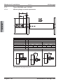
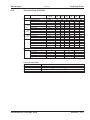
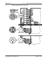
1
Cartridge DDR
Deutsch
English
Italiano
Español
Synchron Servomotor für Direktantriebe
Synchronous Servomotors for Direct Drives
Servomotori Sincroni per gli azionamenti diretti
Servomotores Sincronos para las impulsiones directas
Produkthandbuch / Product Manual / Manuale del Prodotto/ Manual del producto
Edition 05/2011
European Version (CE region)
Bewahren Sie das Handbuch als Produktbestandteil während
der Lebensdauer des Produktes auf. Geben Sie das Handbuch
an nachfolgende Benutzer oder Besitzer des Produktes weiter.
Keep the manual as a product component during the life span of
the product. Pass the manual to future users / owners of the
product.
Conservare il manuale per l’intera durata del prodotto. In caso di
cambio di proprietà il manuale deve essere fornito al nuovo utilizzatore quale parte integrante del prodotto.
Conserve el manual durante toda la vida útil del producto.
Entregue el manual a posteriores usuarios o propietarios del
producto.
File ddc_deis.***
History
Edition
Remarks
10 / 2010
First multilingual edition
12 / 2010
Company name and address, CE certificate
05 / 2011
Motor power cable diameter updated
Technische Änderungen, die der Verbesserung der Geräte dienen, vorbehalten!
Originalbetriebsanleitung, gedruckt in der BRD
Alle Rechte vorbehalten. Kein Teil des Werkes darf in irgendeiner Form (Druck, Fotokopie, Mikrofilm oder in
einem anderen Verfahren) ohne schriftliche Genehmigung der Firma Kollmorgen Europe GmbH reproduziert
oder unter Verwendung elektronischer Systeme verarbeitet, vervielfältigt oder verbreitet werden.
Technical changes to improve the performance of the equipment may be made without prior notice!
Translation of the original manual, printed in the Federal Republic of Germany
All rights reserved. No part of this work may be reproduced in any form (by printing, photocopying, microfilm
or any other method) or stored, processed, copied or distributed by electronic means without the written permission of Kollmorgen Europe GmbH.
Il produttore si riserva la facoltà di apportare modifiche tecniche volte al miglioramento degli apparecchi
Traduzione del manuale originale, stampato nella Repubblica federale tedesca
Tutti i diritti riservati. Nessuna parte di questo documento può essere rielaborata, riprodotta in qualsiasi
forma (stampa, fotocopia, microfilm o altro processo) o diffusa mediante l'uso di sistemi elettronici senza l'approvazione scritta della ditta Kollmorgen Europe GmbH o rielaborata, riprodotta o diffusa mediante l’uso di
sistemi elettronici.
Reservado el derecho de introducir modificaciones técnicas para la mejora de los equipos
Traducción del manual original, impreso en la RFA
Reservados todos los derechos. Prohibida la reproducción total o parcial de la presente obra por cualquier
medio (impresión, fotocopia, microfilm u otros), así como su procesamiento, reproducción y divulgación por
medio de sistemas electrónicos, sin expresa autorización escrita de la empresa Kollmorgen Europe GmbH.e
Kollmorgen
05/2011
Inhaltsverzeichnis
Seite
1.1
1.2
1.3
1.4
Allgemeines
Über dieses Handbuch. . . . . . . . . . . . . . . . . . . . . . . . . . . . . . . . . . . . . . . . . . . . . . . . . . . . . . . . . . . . . . . . . . . .
Zielgruppe . . . . . . . . . . . . . . . . . . . . . . . . . . . . . . . . . . . . . . . . . . . . . . . . . . . . . . . . . . . . . . . . . . . . . . . . . . . . .
Verwendete Symbole . . . . . . . . . . . . . . . . . . . . . . . . . . . . . . . . . . . . . . . . . . . . . . . . . . . . . . . . . . . . . . . . . . . . .
Verwendete Abkürzungen . . . . . . . . . . . . . . . . . . . . . . . . . . . . . . . . . . . . . . . . . . . . . . . . . . . . . . . . . . . . . . . . .
2.1
2.2
2.3
Sicherheit
Sicherheitshinweise . . . . . . . . . . . . . . . . . . . . . . . . . . . . . . . . . . . . . . . . . . . . . . . . . . . . . . . . . . . . . . . . . . . . . 10
Bestimmungsgemäße Verwendung . . . . . . . . . . . . . . . . . . . . . . . . . . . . . . . . . . . . . . . . . . . . . . . . . . . . . . . . . 11
Nicht bestimmungsgemäße Verwendung. . . . . . . . . . . . . . . . . . . . . . . . . . . . . . . . . . . . . . . . . . . . . . . . . . . . . 11
3.1
Gültige Standards
EG-Konformitätserklärung . . . . . . . . . . . . . . . . . . . . . . . . . . . . . . . . . . . . . . . . . . . . . . . . . . . . . . . . . . . . . . . . 12
4.1
4.2
4.3
4.4
4.5
4.6
Handhabung
Transport . . . . . . . . . . . . . . . . . . . . . . . . . . . . . . . . . . . . . . . . . . . . . . . . . . . . . . . . . . . . . . . . . . . . . . . . . . . . .
Verpackung . . . . . . . . . . . . . . . . . . . . . . . . . . . . . . . . . . . . . . . . . . . . . . . . . . . . . . . . . . . . . . . . . . . . . . . . . . .
Lagerung . . . . . . . . . . . . . . . . . . . . . . . . . . . . . . . . . . . . . . . . . . . . . . . . . . . . . . . . . . . . . . . . . . . . . . . . . . . . .
Wartung / Reinigung . . . . . . . . . . . . . . . . . . . . . . . . . . . . . . . . . . . . . . . . . . . . . . . . . . . . . . . . . . . . . . . . . . . .
Reparatur . . . . . . . . . . . . . . . . . . . . . . . . . . . . . . . . . . . . . . . . . . . . . . . . . . . . . . . . . . . . . . . . . . . . . . . . . . . . .
Entsorgung. . . . . . . . . . . . . . . . . . . . . . . . . . . . . . . . . . . . . . . . . . . . . . . . . . . . . . . . . . . . . . . . . . . . . . . . . . . .
5.1
5.2
5.3
Produktidentifizierung
Lieferumfang . . . . . . . . . . . . . . . . . . . . . . . . . . . . . . . . . . . . . . . . . . . . . . . . . . . . . . . . . . . . . . . . . . . . . . . . . . 14
Typenschild . . . . . . . . . . . . . . . . . . . . . . . . . . . . . . . . . . . . . . . . . . . . . . . . . . . . . . . . . . . . . . . . . . . . . . . . . . . 14
Typenschlüssel . . . . . . . . . . . . . . . . . . . . . . . . . . . . . . . . . . . . . . . . . . . . . . . . . . . . . . . . . . . . . . . . . . . . . . . . 15
2
3
4
5
6
16
16
16
17
17
17
17
17
17
Mechanische Installation
Wichtige Hinweise . . . . . . . . . . . . . . . . . . . . . . . . . . . . . . . . . . . . . . . . . . . . . . . . . . . . . . . . . . . . . . . . . . . . . .
Typen C04/CH04, C05/CH05 und C06/CH06 . . . . . . . . . . . . . . . . . . . . . . . . . . . . . . . . . . . . . . . . . . . . . . . . .
7.2.1
Anforderungen an Montageflansch und Welle . . . . . . . . . . . . . . . . . . . . . . . . . . . . . . . . . . . . . . . . . . . .
7.2.2
Montage . . . . . . . . . . . . . . . . . . . . . . . . . . . . . . . . . . . . . . . . . . . . . . . . . . . . . . . . . . . . . . . . . . . . . . . . .
7.2.3
Demontage . . . . . . . . . . . . . . . . . . . . . . . . . . . . . . . . . . . . . . . . . . . . . . . . . . . . . . . . . . . . . . . . . . . . . .
7.3
Typen C09/CH09 und C13/CH13. . . . . . . . . . . . . . . . . . . . . . . . . . . . . . . . . . . . . . . . . . . . . . . . . . . . . . . . . . .
7.3.1
Anforderungen an Montageflansch und Welle . . . . . . . . . . . . . . . . . . . . . . . . . . . . . . . . . . . . . . . . . . . .
7.3.2
Montage . . . . . . . . . . . . . . . . . . . . . . . . . . . . . . . . . . . . . . . . . . . . . . . . . . . . . . . . . . . . . . . . . . . . . . . . .
7.3.3
Demontage . . . . . . . . . . . . . . . . . . . . . . . . . . . . . . . . . . . . . . . . . . . . . . . . . . . . . . . . . . . . . . . . . . . . . .
18
19
19
20
21
22
22
23
24
7.1
7.2
8
8.1
8.2
8.3
Elektrische Installation
Sicherheitshinweise . . . . . . . . . . . . . . . . . . . . . . . . . . . . . . . . . . . . . . . . . . . . . . . . . . . . . . . . . . . . . . . . . . . . . 25
Leitfaden für die elektrische Installation . . . . . . . . . . . . . . . . . . . . . . . . . . . . . . . . . . . . . . . . . . . . . . . . . . . . . . 25
Anschluss der Motoren mit vorkonfektionierten Kabeln . . . . . . . . . . . . . . . . . . . . . . . . . . . . . . . . . . . . . . . . . . 26
9.1
9.2
9.3
Inbetriebnahme
Wichtige Hinweise . . . . . . . . . . . . . . . . . . . . . . . . . . . . . . . . . . . . . . . . . . . . . . . . . . . . . . . . . . . . . . . . . . . . . . 27
Leitfaden für die Inbetriebnahme . . . . . . . . . . . . . . . . . . . . . . . . . . . . . . . . . . . . . . . . . . . . . . . . . . . . . . . . . . . 27
Beseitigen von Störungen . . . . . . . . . . . . . . . . . . . . . . . . . . . . . . . . . . . . . . . . . . . . . . . . . . . . . . . . . . . . . . . . 28
9
10
13
13
13
13
13
13
Technische Beschreibung
Allgemeine technische Daten. . . . . . . . . . . . . . . . . . . . . . . . . . . . . . . . . . . . . . . . . . . . . . . . . . . . . . . . . . . . . .
6.1.1
Bauform . . . . . . . . . . . . . . . . . . . . . . . . . . . . . . . . . . . . . . . . . . . . . . . . . . . . . . . . . . . . . . . . . . . . . . . . .
6.1.2
Flansch . . . . . . . . . . . . . . . . . . . . . . . . . . . . . . . . . . . . . . . . . . . . . . . . . . . . . . . . . . . . . . . . . . . . . . . . .
6.1.3
Schutzart . . . . . . . . . . . . . . . . . . . . . . . . . . . . . . . . . . . . . . . . . . . . . . . . . . . . . . . . . . . . . . . . . . . . . . . .
6.1.4
Isolierstoffklasse . . . . . . . . . . . . . . . . . . . . . . . . . . . . . . . . . . . . . . . . . . . . . . . . . . . . . . . . . . . . . . . . . .
6.1.5
Oberfläche . . . . . . . . . . . . . . . . . . . . . . . . . . . . . . . . . . . . . . . . . . . . . . . . . . . . . . . . . . . . . . . . . . . . . . .
6.1.6
Schutzeinrichtung . . . . . . . . . . . . . . . . . . . . . . . . . . . . . . . . . . . . . . . . . . . . . . . . . . . . . . . . . . . . . . . . .
6.1.7
Anschlusstechnik . . . . . . . . . . . . . . . . . . . . . . . . . . . . . . . . . . . . . . . . . . . . . . . . . . . . . . . . . . . . . . . . . .
6.1.8
Rückführeinheit . . . . . . . . . . . . . . . . . . . . . . . . . . . . . . . . . . . . . . . . . . . . . . . . . . . . . . . . . . . . . . . . . . .
6.1
7
9
9
9
9
Technische Daten
10.1 Begriffsdefinitionen. . . . . . . . . . . . . . . . . . . . . . . . . . . . . . . . . . . . . . . . . . . . . . . . . . . . . . . . . . . . . . . . . . . . . . 29
Servomotoren Cartridge DDR
Deutsch - 3
DEUTSCH
toc dr uc k
1
Contents
05/2011
Kollmorgen
Page
11
General
11.1 About this manual . . . . . . . . . . . . . . . . . . . . . . . . . . . . . . . . . . . . . . . . . . . . . . . . . . . . . . . . . . . . . . . . . . . . . .
11.2 Target group . . . . . . . . . . . . . . . . . . . . . . . . . . . . . . . . . . . . . . . . . . . . . . . . . . . . . . . . . . . . . . . . . . . . . . . . . .
11.3 Symbols used. . . . . . . . . . . . . . . . . . . . . . . . . . . . . . . . . . . . . . . . . . . . . . . . . . . . . . . . . . . . . . . . . . . . . . . . . .
11.4 Abbreviations used. . . . . . . . . . . . . . . . . . . . . . . . . . . . . . . . . . . . . . . . . . . . . . . . . . . . . . . . . . . . . . . . . . . . . .
31
31
31
31
Safety
12.1 Safety Notes. . . . . . . . . . . . . . . . . . . . . . . . . . . . . . . . . . . . . . . . . . . . . . . . . . . . . . . . . . . . . . . . . . . . . . . . . . . 32
12.2 Use as directed . . . . . . . . . . . . . . . . . . . . . . . . . . . . . . . . . . . . . . . . . . . . . . . . . . . . . . . . . . . . . . . . . . . . . . . . 33
12.3 Prohibited use . . . . . . . . . . . . . . . . . . . . . . . . . . . . . . . . . . . . . . . . . . . . . . . . . . . . . . . . . . . . . . . . . . . . . . . . . 33
13
Standards
13.1 EC Declaration of Conformity. . . . . . . . . . . . . . . . . . . . . . . . . . . . . . . . . . . . . . . . . . . . . . . . . . . . . . . . . . . . . . 34
14
Handling
14.1 Transport . . . . . . . . . . . . . . . . . . . . . . . . . . . . . . . . . . . . . . . . . . . . . . . . . . . . . . . . . . . . . . . . . . . . . . . . . . . . .
14.2 Packaging . . . . . . . . . . . . . . . . . . . . . . . . . . . . . . . . . . . . . . . . . . . . . . . . . . . . . . . . . . . . . . . . . . . . . . . . . . . .
14.3 Storage . . . . . . . . . . . . . . . . . . . . . . . . . . . . . . . . . . . . . . . . . . . . . . . . . . . . . . . . . . . . . . . . . . . . . . . . . . . . . .
14.4 Maintenance / Cleaning . . . . . . . . . . . . . . . . . . . . . . . . . . . . . . . . . . . . . . . . . . . . . . . . . . . . . . . . . . . . . . . . . .
14.5 Repair . . . . . . . . . . . . . . . . . . . . . . . . . . . . . . . . . . . . . . . . . . . . . . . . . . . . . . . . . . . . . . . . . . . . . . . . . . . . . . .
14.6 Disposal . . . . . . . . . . . . . . . . . . . . . . . . . . . . . . . . . . . . . . . . . . . . . . . . . . . . . . . . . . . . . . . . . . . . . . . . . . . . . .
ENGLISH
12
35
35
35
35
35
35
15
Package
15.1 Delivery package . . . . . . . . . . . . . . . . . . . . . . . . . . . . . . . . . . . . . . . . . . . . . . . . . . . . . . . . . . . . . . . . . . . . . . . 36
15.2 Nameplate . . . . . . . . . . . . . . . . . . . . . . . . . . . . . . . . . . . . . . . . . . . . . . . . . . . . . . . . . . . . . . . . . . . . . . . . . . . . 36
15.3 Model number description . . . . . . . . . . . . . . . . . . . . . . . . . . . . . . . . . . . . . . . . . . . . . . . . . . . . . . . . . . . . . . . . 37
16
Technical Description
16.1 General technical data . . . . . . . . . . . . . . . . . . . . . . . . . . . . . . . . . . . . . . . . . . . . . . . . . . . . . . . . . . . . . . . . . . .
16.1.1
Design . . . . . . . . . . . . . . . . . . . . . . . . . . . . . . . . . . . . . . . . . . . . . . . . . . . . . . . . . . . . . . . . . . . . . . . . . .
16.1.2
Flange . . . . . . . . . . . . . . . . . . . . . . . . . . . . . . . . . . . . . . . . . . . . . . . . . . . . . . . . . . . . . . . . . . . . . . . . . .
16.1.3
Protection class . . . . . . . . . . . . . . . . . . . . . . . . . . . . . . . . . . . . . . . . . . . . . . . . . . . . . . . . . . . . . . . . . . .
16.1.4
Insulation material class. . . . . . . . . . . . . . . . . . . . . . . . . . . . . . . . . . . . . . . . . . . . . . . . . . . . . . . . . . . . .
16.1.5
Surface . . . . . . . . . . . . . . . . . . . . . . . . . . . . . . . . . . . . . . . . . . . . . . . . . . . . . . . . . . . . . . . . . . . . . . . . .
16.1.6
Protective device . . . . . . . . . . . . . . . . . . . . . . . . . . . . . . . . . . . . . . . . . . . . . . . . . . . . . . . . . . . . . . . . . .
16.1.7
Connection method . . . . . . . . . . . . . . . . . . . . . . . . . . . . . . . . . . . . . . . . . . . . . . . . . . . . . . . . . . . . . . . .
16.1.8
Feedback . . . . . . . . . . . . . . . . . . . . . . . . . . . . . . . . . . . . . . . . . . . . . . . . . . . . . . . . . . . . . . . . . . . . . . . .
38
38
38
39
39
39
39
39
39
Mechanical Installation
17.1 Important Notes . . . . . . . . . . . . . . . . . . . . . . . . . . . . . . . . . . . . . . . . . . . . . . . . . . . . . . . . . . . . . . . . . . . . . . . .
17.2 Types C04/CH04, C05/CH05 and C06/CH06 . . . . . . . . . . . . . . . . . . . . . . . . . . . . . . . . . . . . . . . . . . . . . . . . .
17.2.1
Mounting flange and shaft requirements . . . . . . . . . . . . . . . . . . . . . . . . . . . . . . . . . . . . . . . . . . . . . . . .
17.2.2
Mounting . . . . . . . . . . . . . . . . . . . . . . . . . . . . . . . . . . . . . . . . . . . . . . . . . . . . . . . . . . . . . . . . . . . . . . . .
17.2.3
Deismounting . . . . . . . . . . . . . . . . . . . . . . . . . . . . . . . . . . . . . . . . . . . . . . . . . . . . . . . . . . . . . . . . . . . . .
17.3 Types C09/CH09 and C13/CH13 . . . . . . . . . . . . . . . . . . . . . . . . . . . . . . . . . . . . . . . . . . . . . . . . . . . . . . . . . . .
17.3.1
Mounting flange and shaft requirements . . . . . . . . . . . . . . . . . . . . . . . . . . . . . . . . . . . . . . . . . . . . . . . .
17.3.2
Mounting . . . . . . . . . . . . . . . . . . . . . . . . . . . . . . . . . . . . . . . . . . . . . . . . . . . . . . . . . . . . . . . . . . . . . . . .
17.3.3
Deismounting . . . . . . . . . . . . . . . . . . . . . . . . . . . . . . . . . . . . . . . . . . . . . . . . . . . . . . . . . . . . . . . . . . . . .
40
41
41
42
43
44
44
45
46
17
18
Electrical Installation
18.1 Safety notes . . . . . . . . . . . . . . . . . . . . . . . . . . . . . . . . . . . . . . . . . . . . . . . . . . . . . . . . . . . . . . . . . . . . . . . . . . . 47
18.2 Guide for electrical installation . . . . . . . . . . . . . . . . . . . . . . . . . . . . . . . . . . . . . . . . . . . . . . . . . . . . . . . . . . . . . 47
18.3 Connection of the motors with preassembled cables . . . . . . . . . . . . . . . . . . . . . . . . . . . . . . . . . . . . . . . . . . . . 48
19
Setup
19.1 Important notes . . . . . . . . . . . . . . . . . . . . . . . . . . . . . . . . . . . . . . . . . . . . . . . . . . . . . . . . . . . . . . . . . . . . . . . . 49
19.2 Guide for setup. . . . . . . . . . . . . . . . . . . . . . . . . . . . . . . . . . . . . . . . . . . . . . . . . . . . . . . . . . . . . . . . . . . . . . . . . 49
19.3 Trouble Shooting . . . . . . . . . . . . . . . . . . . . . . . . . . . . . . . . . . . . . . . . . . . . . . . . . . . . . . . . . . . . . . . . . . . . . . . 50
20
Technical Data
20.1 Definition of Terms . . . . . . . . . . . . . . . . . . . . . . . . . . . . . . . . . . . . . . . . . . . . . . . . . . . . . . . . . . . . . . . . . . . . . . 51
English - 4
Servomotors Cartridge DDR
Kollmorgen
05/2011
Sommario
Pagina
Indicazoni generali
21.1 Questo manuale. . . . . . . . . . . . . . . . . . . . . . . . . . . . . . . . . . . . . . . . . . . . . . . . . . . . . . . . . . . . . . . . . . . . . . . .
21.2 Gruppo di obiettivo . . . . . . . . . . . . . . . . . . . . . . . . . . . . . . . . . . . . . . . . . . . . . . . . . . . . . . . . . . . . . . . . . . . . . .
21.3 Simboli utilizzati . . . . . . . . . . . . . . . . . . . . . . . . . . . . . . . . . . . . . . . . . . . . . . . . . . . . . . . . . . . . . . . . . . . . . . . .
21.4 Abbreviazioni utilizzati . . . . . . . . . . . . . . . . . . . . . . . . . . . . . . . . . . . . . . . . . . . . . . . . . . . . . . . . . . . . . . . . . . .
53
53
53
53
22
Sicurezza
22.1 Indicazioni di sicurezza . . . . . . . . . . . . . . . . . . . . . . . . . . . . . . . . . . . . . . . . . . . . . . . . . . . . . . . . . . . . . . . . . . 54
22.2 Uso conforme. . . . . . . . . . . . . . . . . . . . . . . . . . . . . . . . . . . . . . . . . . . . . . . . . . . . . . . . . . . . . . . . . . . . . . . . . . 55
22.3 Uso conforme vietato . . . . . . . . . . . . . . . . . . . . . . . . . . . . . . . . . . . . . . . . . . . . . . . . . . . . . . . . . . . . . . . . . . . . 55
23
Norme validi
23.1 EC Declaration of Conformity. . . . . . . . . . . . . . . . . . . . . . . . . . . . . . . . . . . . . . . . . . . . . . . . . . . . . . . . . . . . . . 56
24
Maneggiamento
24.1 Trasporto . . . . . . . . . . . . . . . . . . . . . . . . . . . . . . . . . . . . . . . . . . . . . . . . . . . . . . . . . . . . . . . . . . . . . . . . . . . . .
24.2 Imballaggio. . . . . . . . . . . . . . . . . . . . . . . . . . . . . . . . . . . . . . . . . . . . . . . . . . . . . . . . . . . . . . . . . . . . . . . . . . . .
24.3 Stoccaggio . . . . . . . . . . . . . . . . . . . . . . . . . . . . . . . . . . . . . . . . . . . . . . . . . . . . . . . . . . . . . . . . . . . . . . . . . . . .
24.4 Manutenzione / Puliza . . . . . . . . . . . . . . . . . . . . . . . . . . . . . . . . . . . . . . . . . . . . . . . . . . . . . . . . . . . . . . . . . . .
24.5 Riparazioni . . . . . . . . . . . . . . . . . . . . . . . . . . . . . . . . . . . . . . . . . . . . . . . . . . . . . . . . . . . . . . . . . . . . . . . . . . . .
24.6 Smaltimento . . . . . . . . . . . . . . . . . . . . . . . . . . . . . . . . . . . . . . . . . . . . . . . . . . . . . . . . . . . . . . . . . . . . . . . . . . .
57
57
57
57
57
57
25
Identificazione del prodotto
25.1 Dotazione. . . . . . . . . . . . . . . . . . . . . . . . . . . . . . . . . . . . . . . . . . . . . . . . . . . . . . . . . . . . . . . . . . . . . . . . . . . . . 58
25.2 Targhetta di omologazione. . . . . . . . . . . . . . . . . . . . . . . . . . . . . . . . . . . . . . . . . . . . . . . . . . . . . . . . . . . . . . . . 58
25.3 Codici dei modelli . . . . . . . . . . . . . . . . . . . . . . . . . . . . . . . . . . . . . . . . . . . . . . . . . . . . . . . . . . . . . . . . . . . . . . . 59
26
Descrizione tecnizi
26.1 Dati tecnici generali . . . . . . . . . . . . . . . . . . . . . . . . . . . . . . . . . . . . . . . . . . . . . . . . . . . . . . . . . . . . . . . . . . . . .
26.1.1
Forma costructtiva . . . . . . . . . . . . . . . . . . . . . . . . . . . . . . . . . . . . . . . . . . . . . . . . . . . . . . . . . . . . . . . . .
26.1.2
Flangia . . . . . . . . . . . . . . . . . . . . . . . . . . . . . . . . . . . . . . . . . . . . . . . . . . . . . . . . . . . . . . . . . . . . . . . . . .
26.1.3
Grado di protezione . . . . . . . . . . . . . . . . . . . . . . . . . . . . . . . . . . . . . . . . . . . . . . . . . . . . . . . . . . . . . . . .
26.1.4
Classe di isolamento . . . . . . . . . . . . . . . . . . . . . . . . . . . . . . . . . . . . . . . . . . . . . . . . . . . . . . . . . . . . . . .
26.1.5
Superficie . . . . . . . . . . . . . . . . . . . . . . . . . . . . . . . . . . . . . . . . . . . . . . . . . . . . . . . . . . . . . . . . . . . . . . .
26.1.6
Dispositivo di protezione . . . . . . . . . . . . . . . . . . . . . . . . . . . . . . . . . . . . . . . . . . . . . . . . . . . . . . . . . . . .
26.1.7
Sistema di collegamento . . . . . . . . . . . . . . . . . . . . . . . . . . . . . . . . . . . . . . . . . . . . . . . . . . . . . . . . . . . .
26.1.8
Unità di retroazione . . . . . . . . . . . . . . . . . . . . . . . . . . . . . . . . . . . . . . . . . . . . . . . . . . . . . . . . . . . . . . . .
60
60
60
61
61
61
61
61
61
Installazione meccanica
27.1 Indicazioni importanti . . . . . . . . . . . . . . . . . . . . . . . . . . . . . . . . . . . . . . . . . . . . . . . . . . . . . . . . . . . . . . . . . . . .
27.2 Modelli C04/CH04, C05/CH05 e C06/CH06. . . . . . . . . . . . . . . . . . . . . . . . . . . . . . . . . . . . . . . . . . . . . . . . . . .
27.2.1
Requisiti per flangia di montaggio e albero . . . . . . . . . . . . . . . . . . . . . . . . . . . . . . . . . . . . . . . . . . . . . .
27.2.2
Montaggio . . . . . . . . . . . . . . . . . . . . . . . . . . . . . . . . . . . . . . . . . . . . . . . . . . . . . . . . . . . . . . . . . . . . . . .
27.2.3
Smontaggio . . . . . . . . . . . . . . . . . . . . . . . . . . . . . . . . . . . . . . . . . . . . . . . . . . . . . . . . . . . . . . . . . . . . . .
27.3 Modelli C09/CH09 e C13/CH13 . . . . . . . . . . . . . . . . . . . . . . . . . . . . . . . . . . . . . . . . . . . . . . . . . . . . . . . . . . . .
27.3.1
Requisiti per flangia di montaggio e albero . . . . . . . . . . . . . . . . . . . . . . . . . . . . . . . . . . . . . . . . . . . . . .
27.3.2
Montaggio . . . . . . . . . . . . . . . . . . . . . . . . . . . . . . . . . . . . . . . . . . . . . . . . . . . . . . . . . . . . . . . . . . . . . . .
27.3.3
Smontaggio . . . . . . . . . . . . . . . . . . . . . . . . . . . . . . . . . . . . . . . . . . . . . . . . . . . . . . . . . . . . . . . . . . . . . .
62
63
63
64
65
66
66
67
68
27
28
Installazione elettrica
28.1 Indicazioni di sicurezza . . . . . . . . . . . . . . . . . . . . . . . . . . . . . . . . . . . . . . . . . . . . . . . . . . . . . . . . . . . . . . . . . . 69
28.2 Guida ad installazione elettrica . . . . . . . . . . . . . . . . . . . . . . . . . . . . . . . . . . . . . . . . . . . . . . . . . . . . . . . . . . . . 69
28.3 Collegamento dei motori . . . . . . . . . . . . . . . . . . . . . . . . . . . . . . . . . . . . . . . . . . . . . . . . . . . . . . . . . . . . . . . . . 70
29
Messa in funzione
29.1 Indicazioni importanti . . . . . . . . . . . . . . . . . . . . . . . . . . . . . . . . . . . . . . . . . . . . . . . . . . . . . . . . . . . . . . . . . . . . 71
29.2 Guida ad messa in funzione. . . . . . . . . . . . . . . . . . . . . . . . . . . . . . . . . . . . . . . . . . . . . . . . . . . . . . . . . . . . . . . 71
29.3 Eliminazione dei guasti . . . . . . . . . . . . . . . . . . . . . . . . . . . . . . . . . . . . . . . . . . . . . . . . . . . . . . . . . . . . . . . . . . 72
30
Dati tecnici
30.1 Definizioni . . . . . . . . . . . . . . . . . . . . . . . . . . . . . . . . . . . . . . . . . . . . . . . . . . . . . . . . . . . . . . . . . . . . . . . . . . . . 73
Servomotori Cartridge DDR
Italiano - 5
ITALIANO
21
Sumario
05/2011
Kollmorgen
Página
31
Generalidades
31.1 Sobre este manual . . . . . . . . . . . . . . . . . . . . . . . . . . . . . . . . . . . . . . . . . . . . . . . . . . . . . . . . . . . . . . . . . . . . . .
31.2 Destinatarios . . . . . . . . . . . . . . . . . . . . . . . . . . . . . . . . . . . . . . . . . . . . . . . . . . . . . . . . . . . . . . . . . . . . . . . . . .
31.3 Símbolos utilizados . . . . . . . . . . . . . . . . . . . . . . . . . . . . . . . . . . . . . . . . . . . . . . . . . . . . . . . . . . . . . . . . . . . . .
31.4 Abreviaturas utilizadas . . . . . . . . . . . . . . . . . . . . . . . . . . . . . . . . . . . . . . . . . . . . . . . . . . . . . . . . . . . . . . . . . . .
75
75
75
75
32
Seguridad
32.1 Instrucciones de seguridad . . . . . . . . . . . . . . . . . . . . . . . . . . . . . . . . . . . . . . . . . . . . . . . . . . . . . . . . . . . . . . . 76
32.2 Utilización conforme. . . . . . . . . . . . . . . . . . . . . . . . . . . . . . . . . . . . . . . . . . . . . . . . . . . . . . . . . . . . . . . . . . . . . 77
32.3 Uso indebido . . . . . . . . . . . . . . . . . . . . . . . . . . . . . . . . . . . . . . . . . . . . . . . . . . . . . . . . . . . . . . . . . . . . . . . . . . 77
33
Normas válidas
33.1 EC Declaration of Conformity. . . . . . . . . . . . . . . . . . . . . . . . . . . . . . . . . . . . . . . . . . . . . . . . . . . . . . . . . . . . . . 78
34
Manipulación
34.1 Transporte . . . . . . . . . . . . . . . . . . . . . . . . . . . . . . . . . . . . . . . . . . . . . . . . . . . . . . . . . . . . . . . . . . . . . . . . . . . .
34.2 Embalaje . . . . . . . . . . . . . . . . . . . . . . . . . . . . . . . . . . . . . . . . . . . . . . . . . . . . . . . . . . . . . . . . . . . . . . . . . . . . .
34.3 Almacenamiento . . . . . . . . . . . . . . . . . . . . . . . . . . . . . . . . . . . . . . . . . . . . . . . . . . . . . . . . . . . . . . . . . . . . . . .
34.4 Advertenzia / Limpieza. . . . . . . . . . . . . . . . . . . . . . . . . . . . . . . . . . . . . . . . . . . . . . . . . . . . . . . . . . . . . . . . . . .
34.5 Reparación. . . . . . . . . . . . . . . . . . . . . . . . . . . . . . . . . . . . . . . . . . . . . . . . . . . . . . . . . . . . . . . . . . . . . . . . . . . .
34.6 Eliminación. . . . . . . . . . . . . . . . . . . . . . . . . . . . . . . . . . . . . . . . . . . . . . . . . . . . . . . . . . . . . . . . . . . . . . . . . . . .
79
79
79
79
79
79
35
Identificación del producto
35.1 Volumen de suministro. . . . . . . . . . . . . . . . . . . . . . . . . . . . . . . . . . . . . . . . . . . . . . . . . . . . . . . . . . . . . . . . . . . 80
35.2 Placa de identificación . . . . . . . . . . . . . . . . . . . . . . . . . . . . . . . . . . . . . . . . . . . . . . . . . . . . . . . . . . . . . . . . . . . 80
35.3 Codificación de modelo . . . . . . . . . . . . . . . . . . . . . . . . . . . . . . . . . . . . . . . . . . . . . . . . . . . . . . . . . . . . . . . . . . 81
36
Descripción técnica
36.1 Datos técnicos generales. . . . . . . . . . . . . . . . . . . . . . . . . . . . . . . . . . . . . . . . . . . . . . . . . . . . . . . . . . . . . . . . .
36.1.1
Forma de diseño . . . . . . . . . . . . . . . . . . . . . . . . . . . . . . . . . . . . . . . . . . . . . . . . . . . . . . . . . . . . . . . . . .
36.1.2
Brida . . . . . . . . . . . . . . . . . . . . . . . . . . . . . . . . . . . . . . . . . . . . . . . . . . . . . . . . . . . . . . . . . . . . . . . . . . .
36.1.3
Tipo de protección . . . . . . . . . . . . . . . . . . . . . . . . . . . . . . . . . . . . . . . . . . . . . . . . . . . . . . . . . . . . . . . . .
36.1.4
Clase de material aislante . . . . . . . . . . . . . . . . . . . . . . . . . . . . . . . . . . . . . . . . . . . . . . . . . . . . . . . . . . .
36.1.5
Superficie . . . . . . . . . . . . . . . . . . . . . . . . . . . . . . . . . . . . . . . . . . . . . . . . . . . . . . . . . . . . . . . . . . . . . . . .
36.1.6
Dispositivo protector . . . . . . . . . . . . . . . . . . . . . . . . . . . . . . . . . . . . . . . . . . . . . . . . . . . . . . . . . . . . . . .
36.1.7
Sistema de conexión . . . . . . . . . . . . . . . . . . . . . . . . . . . . . . . . . . . . . . . . . . . . . . . . . . . . . . . . . . . . . . .
36.1.8
Unidad de realimentación (Feedback) . . . . . . . . . . . . . . . . . . . . . . . . . . . . . . . . . . . . . . . . . . . . . . . . . .
82
82
82
83
83
83
83
83
83
Instalación mecánica
37.1 Instrucciones importantes . . . . . . . . . . . . . . . . . . . . . . . . . . . . . . . . . . . . . . . . . . . . . . . . . . . . . . . . . . . . . . . .
37.2 Tipos C04/CH04, C05/CH05 y C06/CH06 . . . . . . . . . . . . . . . . . . . . . . . . . . . . . . . . . . . . . . . . . . . . . . . . . . . .
37.2.1
Requisitos de la brida de montaje y el eje . . . . . . . . . . . . . . . . . . . . . . . . . . . . . . . . . . . . . . . . . . . . . . .
37.2.2
Montaje . . . . . . . . . . . . . . . . . . . . . . . . . . . . . . . . . . . . . . . . . . . . . . . . . . . . . . . . . . . . . . . . . . . . . . . . .
37.2.3
Desmontaje . . . . . . . . . . . . . . . . . . . . . . . . . . . . . . . . . . . . . . . . . . . . . . . . . . . . . . . . . . . . . . . . . . . . . .
37.3 Tipos C09/CH09 y C13/CH13 . . . . . . . . . . . . . . . . . . . . . . . . . . . . . . . . . . . . . . . . . . . . . . . . . . . . . . . . . . . . .
37.3.1
Requisitos de la brida de montaje y el eje . . . . . . . . . . . . . . . . . . . . . . . . . . . . . . . . . . . . . . . . . . . . . . .
37.3.2
Montaje . . . . . . . . . . . . . . . . . . . . . . . . . . . . . . . . . . . . . . . . . . . . . . . . . . . . . . . . . . . . . . . . . . . . . . . . .
37.3.3
Desmontaje . . . . . . . . . . . . . . . . . . . . . . . . . . . . . . . . . . . . . . . . . . . . . . . . . . . . . . . . . . . . . . . . . . . . . .
84
85
85
86
87
88
88
89
90
ESPAÑOL
37
38
Instalación eléctrica
38.1 Instrucciones de seguridad . . . . . . . . . . . . . . . . . . . . . . . . . . . . . . . . . . . . . . . . . . . . . . . . . . . . . . . . . . . . . . . 91
38.2 Guía de instalación eléctrica . . . . . . . . . . . . . . . . . . . . . . . . . . . . . . . . . . . . . . . . . . . . . . . . . . . . . . . . . . . . . . 91
38.3 Conexión de los motores . . . . . . . . . . . . . . . . . . . . . . . . . . . . . . . . . . . . . . . . . . . . . . . . . . . . . . . . . . . . . . . . . 92
39
Puesta en funcionamento
39.1 Instrucciones importantes . . . . . . . . . . . . . . . . . . . . . . . . . . . . . . . . . . . . . . . . . . . . . . . . . . . . . . . . . . . . . . . . 93
39.2 Guía de puesta en funcionamento . . . . . . . . . . . . . . . . . . . . . . . . . . . . . . . . . . . . . . . . . . . . . . . . . . . . . . . . . . 93
39.3 Eliminación de perturbaciones . . . . . . . . . . . . . . . . . . . . . . . . . . . . . . . . . . . . . . . . . . . . . . . . . . . . . . . . . . . . . 94
40
Datos técnicos
40.1 Definiciones . . . . . . . . . . . . . . . . . . . . . . . . . . . . . . . . . . . . . . . . . . . . . . . . . . . . . . . . . . . . . . . . . . . . . . . . . . . 95
Español - 6
Servomotores Cartridge DDR
Kollmorgen
05/2011
Sumario
Página
41
Technical Data
41.1 Dictionary for technical data tables . . . . . . . . . . . . . . . . . . . . . . . . . . . . . . . . . . . . . . . . . . . . . . . . . . . . . . . . . 96
41.2 Technical Data C04/CH04 . . . . . . . . . . . . . . . . . . . . . . . . . . . . . . . . . . . . . . . . . . . . . . . . . . . . . . . . . . . . . . . . 97
41.3 Technical Data C05/CH05 . . . . . . . . . . . . . . . . . . . . . . . . . . . . . . . . . . . . . . . . . . . . . . . . . . . . . . . . . . . . . . . . 98
41.4 Technical Data C06/CH06 . . . . . . . . . . . . . . . . . . . . . . . . . . . . . . . . . . . . . . . . . . . . . . . . . . . . . . . . . . . . . . . . 99
41.5 Technical Data C09/CH09 . . . . . . . . . . . . . . . . . . . . . . . . . . . . . . . . . . . . . . . . . . . . . . . . . . . . . . . . . . . . . . . 100
41.6 Technical Data C13/CH13 . . . . . . . . . . . . . . . . . . . . . . . . . . . . . . . . . . . . . . . . . . . . . . . . . . . . . . . . . . . . . . . 101
42
Dimension draw ings
42.1 Dimensions C04/CH04. . . . . . . . . . . . . . . . . . . . . . . . . . . . . . . . . . . . . . . . . . . . . . . . . . . . . . . . . . . . . . . . . .
42.2 Dimensions C05/CH05. . . . . . . . . . . . . . . . . . . . . . . . . . . . . . . . . . . . . . . . . . . . . . . . . . . . . . . . . . . . . . . . . .
42.3 Dimensions C06/CH06. . . . . . . . . . . . . . . . . . . . . . . . . . . . . . . . . . . . . . . . . . . . . . . . . . . . . . . . . . . . . . . . . .
42.4 Dimensions C09/CH09. . . . . . . . . . . . . . . . . . . . . . . . . . . . . . . . . . . . . . . . . . . . . . . . . . . . . . . . . . . . . . . . . .
42.5 Dimensions C13/CH13. . . . . . . . . . . . . . . . . . . . . . . . . . . . . . . . . . . . . . . . . . . . . . . . . . . . . . . . . . . . . . . . . .
Wiring diagram Motor & Encoder
ESPAÑOL
43
103
104
105
106
107
Servomotores Cartridge DDR
Español - 7
Kollmorgen
DEUTSCH
05/2011
Diese Seite wurde bewusst leer gelassen.
Deutsch - 8
Servomotoren Cartridge DDR
05/2011
1
Allgemeines
1.1
Über dieses Handbuch
Allgemeines
Dieses Handbuch beschreibt die Synchron-Servomotoren der Serie Cartridge DDR (Standardausführung).
Die Motoren werden im Antriebssystem zusammen mit den Kollmorgen Servoverstärkern betrieben.
Beachten Sie daher die gesamte Dokumentation des Systems, bestehend aus:
— Betriebsanleitung des Servoverstärkers
— Installations-/Inbetriebnahmeanweisung einer eventuell vorhandenen Erweiterungskarte
— Online Hilfe der Inbetriebnahmesoftware des Servoverstärkers
— Zubehörhandbuch
— Technische Beschreibung Motorserie Cartridge DDR (dieses Handbuch)
Weitere Hintergundinformationen finden Sie im "Produkt-WIKI", erreichbar unter
www.wiki-kollmorgen.eu.
1.2
Zielgruppe
Dieses Handbuch richtet sich mit folgenden Anforderungen an Fachpersonal:
Transport:
nur durch Personal mit Kenntnissen in der Behandlung
elektrostatisch gefährdeter Bauelemente
Mech. Installation: nur durch Fachleute mit maschinenbautechnischer Ausbildung
Elektr. Installation: nur durch Fachleute mit elektrotechnischer Ausbildung
Inbetriebnahme:
nur durch Fachleute mit weitreichenden Kenntnissen in
den Bereichen Elektrotechnik / Antriebstechnik
Das Fachpersonal muss folgende Normen kennen und beachten:
IEC 60364 oder IEC 60664
nationale Unfallverhütungsvorschriften
Während des Betriebes der Motoren besteht die Gefahr von Tod oder schweren gesundheitlichen oder materiellen Schäden. Der Betreiber muss daher sicherstellen, dass die Sicherheitshinweise in diesem Handbuch beachtet werden. Der Betreiber muss sicherstellen, dass
alle mit Arbeiten am Motor betrauten Personen das Produkthandbuch gelesen und verstanden haben.
1.3
Verwendete Symbole
Symbol
Bedeutung
Weist auf eine gefährliche Situation hin, die, wenn sie nicht vermieden wird, zum
Tode oder zu schweren, irreversiblen Verletzungen führen wird.
Weist auf eine gefährliche Situation hin, die, wenn sie nicht vermieden wird, zum
Tode oder zu schweren, irreversiblen Verletzungen führen kann.
Weist auf eine gefährliche Situation hin, die, wenn sie nicht vermieden wird, zu leichten Verletzungen führen kann.
Weist auf eine Situation hin, die, wenn sie nicht vermieden wird, zu Beschädigung von
Sachen führen kann.
Dies ist kein Sicherheits-Symbol. Dieses Symbol weist auf wichtige Informationen hin.
1.4
Verwendete Abkürzungen
Siehe Kapitel 10.1 "Begriffsdefinitionen".
Servomotoren Cartridge DDR
Deutsch - 9
DEUTSCH
Kollmorgen
DEUTSCH
Sicherheit
05/2011
2
Sicherheit
2.1
Sicherheitshinweise
l
Der Maschinenhersteller muss eine Gefahrenanalyse für die Maschine erstellen und geeignete Maßnahmen treffen, dass unvorhergesehene Bewegungen nicht zu Schäden an
Personen oder Sachen führen können.
l
Stellen Sie unbedingt die ordnungsgemäße Erdung des Motorgehäuses mit der
PE-Schiene im Schaltschrank als Bezugspotential sicher. Ohne niederohmige Erdung
ist keine personelle Sicherheit gewährleistet.
l
Ziehen Sie keine Stecker während des Betriebs. Es besteht die Gefahr von Tod oder
schweren gesundheitlichen oder materiellen Schäden.
l
Leistungsanschlüsse können Spannung führen, auch wenn sich der Motor nicht dreht.
Lösen Sie die elektrischen Anschlüsse der Motoren nie unter Spannung. In ungünstigen Fällen können Lichtbögen entstehen und Personen und Kontakte schädigen.
l
Warten Sie nach dem Trennen der Servoverstärker von den Versorgungsspannungen
mehrere Minuten, bevor Sie spannungsführende Teile (z.B. Kontakte, Gewindebolzen)
berühren oder Anschlüsse lösen. Kondensatoren im Servoverstärker führen mehrere
Minuten nach Abschalten der Versorgungsspannungen gefährliche Spannungen. Messen Sie zur Sicherheit die Spannung im Zwischenkreis und warten Sie, bis die Spannung unter 40V abgesunken ist.
l
Deutsch - 10
Kollmorgen
Während des Betriebes können Motoren ihrer Schutzart
entsprechend heiße Oberflächen besitzen.
Die Oberflächentemperatur kann 100°C überschreiten.
Messen Sie die Temperatur und warten Sie, bis der Motor auf
40°C abgekühlt ist, bevor Sie ihn berühren.
l
Nur qualifiziertes Fachpersonal darf Arbeiten wie Transport, Montage, Inbetriebnahme
und Instandhaltung ausführen. Qualifiziertes Fachpersonal sind Personen, die mit
Transport, Aufstellung, Montage, Inbetriebnahme und Betrieb von Motoren vertraut
sind und über die ihrer Tätigkeit entsprechenden Qualifikationen verfügen. Das Fachpersonal muss folgende Normen bzw. Richtlinien kennen und beachten:
IEC 60364 oder IEC 60664
nationale Unfallverhütungsvorschriften
l
Lesen Sie vor der Montage und Inbetriebnahme die vorliegende Dokumentation. Falsches Handhaben des Motors kann zu Personen- oder Sachschäden führen. Halten Sie
die technischen Daten und die Angaben zu den Anschlussbedingungen (Typenschild
und Dokumentation) unbedingt ein.
Servomotoren Cartridge DDR
Kollmorgen
2.3
Sicherheit
Bestimmungsgemäße Verwendung
l
Synchron-Servomotoren der Serie Cartridge DDR sind insbesondere als Antrieb für Walzen in
Druckmaschinen, Textilmaschinen, Folienbearbeitungsmaschinen, Verpackungsmaschinen
und ähnliche mit hohen Ansprüchen an die Dynamik konzipiert.
l
Sie dürfen die Motoren nur unter Berücksichtigung der in dieser Dokumentation definierten
Umgebungsbedingungen betreiben.
l
Die Motoren der Serie Cartridge DDR sind ausschließlich dazu bestimmt, von digitalen
Servoverstärkern drehzahl- und/oder drehmomentgeregelt angesteuert zu werden.
l
Die Motoren werden als Bauteile in elektrische Anlagen oder Maschinen eingebaut und dürfen
nur als integrierte Bauteile der Anlage in Betrieb genommen werden.
l
Der in die Motorwicklungen eingebaute Temperatursensor muss ausgewertet und überwacht
werden.
l
Die Konformität des Servosystems zu den in der EG-Konformitätserklärung auf Seite 12 genannten Normen garantieren wir nur, wenn von uns gelieferte Komponenten (Servoverstärker,
Motor, Leitungen usw.) verwendet werden.
Nicht bestimmungsgemäße Verwendung
l
Der Betrieb der Motoren in folgenden Umgebungen ist verboten:
- explosionsgefährdete Bereiche und Umgebungen mit ätzenden und/oder
elektrisch leitenden Säuren, Laugen, Ölen, Dämpfen, Stäuben
- direkt am Netz
l
Der bestimmungsgemäße Betrieb des Motors ist untersagt, wenn die Maschine, in die er eingebaut wurde,
- nicht den Bestimmungen der EG Maschinenrichtlinie entspricht
- nicht die Bestimmung der EMV-Richtlinie erfüllt
- nicht die Bestimmung der Niederspannungs-Richtlinie erfüllt
Servomotoren Cartridge DDR
Deutsch - 11
DEUTSCH
2.2
05/2011
DEUTSCH
Gültige Standards
Kollmorgen
05/2011
3
Gültige Standards
3.1
EG-Konformitätserklärung
Hiermit erklären wir, die Firma
Kollmorgen Europe GmbH
Pempelfurtstraße 1
D-40880 Ratingen
in alleiniger Verantwortung die Konformität der Produktreihe
Motorserie Cartridge DDR
(Typen C04, CH04, C05, CH05, C06, CH06, C09, CH09, C13, CH13)
mit folgenden einschlägigen Bestimmungen:
-
EG-Richtlinie 2004/108/EG
Elektromagnetische Verträglichkeit
Angewendete harmonisierte Norm EN61800-3:07/2005
-
EG-Richtlinie 2006/95/EG
Elektrische Betriebsmittel zur Verwendung innerhalb bestimmter Spannungsgrenzen
Angewendete harmonisierte Norm EN61800-5-1:04/2008
Anbringung der CE-Kennzeichnung
2004
Aussteller:
Produktspezialist Motoren Europa
Johannes Sodermanns
Ratingen, 01.12.2010
Rechtsverbindliche Unterschrift
Diese Erklärung beinhaltet keine Zusicherung von Eigenschaften im Sinne des Produkthaftungsgesetzes.
Die Sicherheits- und Schutzhinweise der Bedienungsanleitung sind in jedem Falle einzuhalten.
Die oben genannte Firma hält folgende technische Dokumentation zur Einsicht bereit:
- vorschriftsmäßige Betriebsanleitung
- Pläne (nur für EU-Behörde)
- Prüfprotokolle (nur für EU-Behörde)
- sonstige technische Dokumentation (nur für EU-Behörde)
Deutsch - 12
Servomotoren Cartridge DDR
4
Handhabung
4.1
Transport
4.2
l
Transport-Temperatur:
Transport-Luftfeuchtigkeit:
l
Nur von qualifiziertem Personal in der recyclebaren Original-Verpackung des Herstellers
l
Vermeiden Sie harte Stöße
l
Überprüfen Sie bei beschädigter Verpackung den Motor auf sichtbare Schäden. Informieren
Sie den Transporteur und gegebenenfalls den Hersteller.
4.4
4.5
-25..+70°C, max. 20K/Stunde schwankend
relative Feuchte 5% - 95% nicht kondensierend
Verpackung
l
Kartonverpackung mit Instapak®-Ausschäumung.
l
Den Kunststoffanteil können Sie an den Lieferanten zurückgeben (siehe "Entsorgung")
Motortyp
C04/CH04
C05/CH05
C06/CH06
4.3
Handhabung
05/2011
Karton
X
X
X
max. Stapelhöhe
10
10
5
Motortyp
C09/CH09
C13/CH13
Karton
X
X
max. Stapelhöhe
5
5
Lagerung
l
Lagertemperatur -25...+55°C, max. 20K/Stunde schwankend
l
Luftfeuchtigkeit relative Feuchte 5% - 95% nicht kondensierend
l
Nur in der recyclebaren Originalverpackung des Herstellers lagern
l
Max. Stapelhöhe:
siehe Tabelle Verpackung
l
Lagerdauer:
ohne Einschränkung
Wartung / Reinigung
l
Wartung und Reinigung nur von qualifiziertem Personal
l
Öffnen der Motoren bedeutet den Verlust der Gewährleistung.
l
Gehäusereinigung mit Isopropanol o.ä., nicht tauchen oder absprühen
Reparatur
Reparaturen des Motors darf nur der Hersteller durchführen, Öffnen der Geräte bedeutet Verlust
der Gewährleistung. Schicken Sie den Motor zur Reparatur an:
Kollmorgen Europe GmbH
Pempelfurtstraße 1
D-40880 Ratingen
4.6
Entsorgung
Gemäß der WEEE-2002/96/EG-Richtlinien nehmen wir Altgeräte und Zubehör zur fachgerechten
Entsorgung zurück, sofern die Transportkosten vom Absender übernommen werden. Senden Sie
die Geräte an:
Kollmorgen Europe GmbH
Pempelfurtstraße 1
D-40880 Ratingen
Servomotoren Cartridge DDR
Deutsch - 13
DEUTSCH
Kollmorgen
DEUTSCH
Produktidentifizierung
Kollmorgen
05/2011
5
Produktidentifizierung
5.1
Lieferumfang
Sie erhalten einen Karton mit Instapak®-Ausschäumung. Enthalten ist:
5.2
l
Motor der Serie Cartridge DDR
l
Produkthandbuch gedruckt, mehrsprachig
Typenschild
Legende:
MODEL
STALL CONT
STALL PEAK
VOLTS
MAX SPEED
CLASS
FREQ
KB
RES L/L@25°C
Typenbezeichnung
I0rms (Stillstandsstrom)
Ipeak (Spitzenstrom)
Nennspannung
Spitzendrehzahl
Isolierstoffklasse (Temperatur)
Netzfrequenz
Spannungskonstante
Wicklungswiderstand bei 25°C
Das Baujahr des Motors ist in der Seriennummer kodiert: die ersten beiden Ziffern der Seriennummer bezeichen das Jahr, z.B. bedeutet "09" 2009.
Deutsch - 14
Servomotoren Cartridge DDR
Kollmorgen
Produktidentifizierung
Typenschlüssel
C 09 1 A - 1 1 - 2 1 0 5 S - xxx
Bauart
C
230 VAC
CH 400/480VAC
Baugröße
04
108mm
05
138mm
06
188mm
09
246mm
13
350mm
Rotorlänge
1 kurz
2 mittel
3 lang
4 extra lang
Wicklung
A
B
C
D
Flansch
1
Standard
Anschlüsse
1
zur Seite (09/13)
2
zur Rückseite (09/13)
3
90° drehbar (04/05/06)
Servomotoren Cartridge DDR
Ausführung
fortlaufende Nummer für
Sonderausführungen
Zertifizierung
_ UL / CE
S CE
Abdichtung
5 abgedichtet
Option Kugellager
0
keine Lagerung
Rückführung
1
EnDAT (alle Typen)
3
BiSS (04/05/06)
Welle
1
mit Klemmkupplung und Passfeder für durchgehende Welle
(09/13)
2
mit Klemmkupplung und Passfeder für Wellenzapfen (09/13)
3
mit Schlitzringkupplung für
Wellenzapfen (04/05/06)
Deutsch - 15
DEUTSCH
5.3
05/2011
DEUTSCH
Technische Beschreibung
Kollmorgen
05/2011
6
Technische Beschreibung
6.1
Allgemeine technische Daten
Umgebungstemperatur
(bei Nenndaten)
5...+40°C bei Aufstellhöhe bis 1000m über NN
Sprechen Sie bei Umgebungstemperaturen über 40°C
und bei gekapseltem Einbau der Motoren unbedingt mit
unserer Applikationsabteilung.
Zulässige Luftfeuchte
(bei Nenndaten)
95% relative Feuchte, nicht betauend
Leistungsreduzierung
(Ströme und Momente)
1%/K im Bereich 40°C...50°C bis 1000m über NN
Bei Aufstellhöhen über 1000m über NN und 40°C
6%
bei 2000m über NN
17% bei 3000m über NN
30% bei 4000m über NN
55% bei 5000m über NN
Keine Leistungsreduzierung bei Aufstellhöhen über
1000m über NN und Temperaturreduzierung
um 10K / 1000m
Technische Daten für jeden Motortyp finden Sie in Kapitel "Technical Data" ab S. 96.
6.1.1
Bauform
Der Motor kann in beliebiger Einbaulage, also auch an horizontalen oder vertikalen Wellen, montiert
werden.
6.1.2
Flansch
Die Cartridge DDR besitzen keinen eignen Flansch, sondern werden mit einer Klemmkupplung und
Zentrierring an den Maschinenflansch montiert. Ein Passring am Motor dient der Zentrierung am
Maschinenflansch, die Klemmkupplung fixiert den integrierten Rotor auf der Maschinenwelle. Der
Motor besitzt keine eigenen Lager.
Die Anforderungen an den Flansch werden in den Kapiteln 7.2 bzw. 7.3 beschrieben.
Bei den Motoren C(H) 09 und C(H) 13 ist eine Version mit Hohlwellenöffnung für durchgehende
Motorwellen verfügbar.
Deutsch - 16
Servomotoren Cartridge DDR
Kollmorgen
Schutzart
Ausführung für Wellenzapfen (2, 3):
Ausführung mit Hohlwelle (1):
6.1.4
Technische Beschreibung
IP65 bei abgedichtetem Maschinenflansch
IP64 bei abgedichtetem Maschinenflansch
Isolierstoffklasse
Die Motoren entsprechen der Isolierstoffklasse F nach IEC 60085 (UL 1446 class F).
6.1.5
Oberfläche
Die Motoren sind mattschwarz mit Polyester pulverbeschichtet, eine Beständigkeit gegen Lösungsmittel (Tri, Verdünnung o.ä.) besteht nicht.
6.1.6
Schutzeinrichtung
In der Standardausführung ist jeder Motor mit einem potentialfreien PTC ausgestattet. Der Schaltpunkt liegt bei 155°C ± 5%. Schutz gegen kurzzeitige, sehr hohe Überlastung bietet der PTC nicht.
Der PTC ist bei Verwendung unserer vorkonfektionierten Encoderleitung in das Überwachungssystem der digitalen Servoverstärker integriert.
6.1.7
Anschlusstechnik
Die Motoren sind mit Steckern für die Leistungsversorgung und die Encodersignale ausgerüstet.
Die Stecker weisen je nach Ausführung entweder zur Seite oder zur Rückseite des Motors oder
sind um 90° drehbar.
Die Gegenstecker gehören nicht zum Lieferumfang. Rückführungs- und Leistungsleitungen bieten
wir Ihnen fertig konfektioniert an.
6.1.8
Rückführeinheit
C(H) yyxx-xx-x1xx
Hochauflösender SinCos-Drehgeber, Singleturn, EnDat ECN1313 (2048 Period)
C(H) 04xx-xx-x3xx, C(H) 05xx-xx-x3xx und C(H) 06xx-xx-x3xx
Hochauflösender SinCos-Drehgeber, Singleturn, Hengstler ACURO AD36 (2048 Period); BiSS
Servomotoren Cartridge DDR
Deutsch - 17
DEUTSCH
6.1.3
05/2011
Mechanische Installation
7
Kollmorgen
05/2011
Mechanische Installation
DEUTSCH
Maßzeichnungen finden Sie im Kapitel "Dimension Drawings" ab S. 103.
7.1
Wichtige Hinweise
Nur Fachleute mit Maschinenbau-Kenntnissen dürfen den Motor montieren.
Deutsch - 18
l
Schützen Sie die Motoren vor unzulässiger Beanspruchung.
Insbesondere dürfen bei Transport und Handhabung keine Bauelemente verbogen und / oder
Isolationsabstände verändert werden
l
Der Einbauort muss frei von leitfähigen und aggressiven Stoffen sein.
Bei gekapseltem Einbau sollten Sie zunächst mit unserer Applikationsabteilung Rücksprache
nehmen.
l
Montieren Sie den Motor nach den Anweisungen ab Seite 19.
Achten Sie bei der Montage darauf, dass der Motor nicht mechanisch überbestimmt befestigt
wird.
l
Stellen Sie die ungehinderte Belüftung der Motoren sicher und beachten Sie die zulässige
Umgebungs- und Flanschtemperatur. Bei Umgebungstemperaturen über 40°C sollten Sie zunächst mit unserer Applikationsabteilung Rücksprache nehmen.
Servomotoren Cartridge DDR
Kollmorgen
05/2011
Mechanische Installation
Typen C04/CH04, C05/CH05 und C06/CH06
7.2.1
Anforderungen an Montageflansch und Welle
DEUTSCH
7.2
Baugröße (C/CH)
041 042 043 041 051 052 053 054 061 062 063
Stahl oder Edelstahl
Material der Welle
N/mm²
380
Streckgrenze der Welle
mm
32
45
71
(A) Ø Welle (-0.015mm)
mm
33
46
72
(B) Ø Welle (-0.015mm)
92.065
118.065
164.065
(C) Ø Passring (±0,025mm) mm
mm
17
48
79
110
35
60
85
110
49
83
117
(D) Wellenlänge (±0.4mm)
mm 61.3 92.3 123.3 154.3 82
107 132 157 104 138 172
(E) Wellenlänge (±1.5mm)
mm
> 5.5
(F) Rezess
mm
± 0.13
Axialspiel der Welle
Rundlauf der Welle
Koaxialität Passring
Rechtwinkligkeit Flansch
±0.10 mm
±0.10 mm
±0.13 mm
Weitere Maße siehe Seiten 103, 104 und 105.
Servomotoren Cartridge DDR
Deutsch - 19
Mechanische Installation
7.2.2
Kollmorgen
05/2011
Montage
DEUTSCH
Fehlerhafte Montage kann Motor und Maschine beschädigen.
A
B
Status vor der Montage
Wenn der Motor nicht montiert ist, befindet sich in Bohrung "A" eine schwarze
Kreuzschlitzschraube und in Bohrung "B" eine silbrige Innensechskantschraube.
Montage des Motors an den Maschinenflansch
Wischen Sie Wellenzapfen und Hohlwellenbohrung sauber. Ein dünner Ölfilm
ist akzeptabel, Fett und andere Verunreinigungen müssen entfernt werden.
Schieben Sie den Cartridge DDR Motor auf die Welle. Verschrauben Sie das
Motorgehäuse kreuzweise mit dem Flansch der Maschine (4 Schrauben, nicht
im Lieferumfang).
A
A
B
A
B
A
B
Deutsch - 20
Klemmkupplung anziehen
Sie erreichen die Klemmschraube durch das mit "A" gekennzeichnete Gewinde.
Entfernen Sie dazu die Kreuzschlitzschraube "A".
Verwenden Sie einen Sechskant mit einem Drehmomentschlüssel und ziehen
Sie die Schraube in "A" an mit
C04X: 12.5 Nm
C05X/C06X: 30 Nm
Nur diese eine Schraube wird für die Klemmkupplung benötigt. Eine nicht
ordnungsgemäß befestigte Klemmkupplung kann zu schweren Schäden
an Motor und Maschine führen.
Sichern für den Betrieb
Entfernen Sie die Innensechskantschraube "B" und schrauben Sie sie mit mindestens 30Nm Anzugsmoment in Gewinde "A".
Schrauben Sie die Kreuzschlitzschraube in das Gewinde "B" mit mindestens
30Nm Anzugsmoment.
Stellen Sie sicher, dass Motor und Last sich ungehindert drehen können.
Verdrehen Sie die Last von Hand, wenn möglich.
Status nach der Montage
Wenn der Motor nicht montiert ist, befindet sich in Bohrung "B" eine schwarze
Kreuzschlitzschraube und in Bohrung "A" eine silbrige Innensechskantschraube.
Servomotoren Cartridge DDR
Kollmorgen
Mechanische Installation
Demontage
A
B
Status vor der Demontage
Wenn der Motor nicht montiert ist, befindet sich in Bohrung "B" eine schwarze
Kreuzschlitzschraube und in Bohrung "A" eine silbrige Innensechskantschraube.
Klemmkupplung lösen
Entfernen Sie die Innensechskantschraube "A".
A
B
Verwenden Sie einen Sechskantschlüssel und lösen Sie die Klemmschraube in
"A".
Demontage des Motors vom Maschinenflansch
Lösen Sie die 4 Flanschschrauben.
Sichern für den Transport
Entfernen Sie die Kreuzschlitzschraube aus dem Gewinde "B".
A
B
A
B
Schrauben Sie die Kreuzschlitzschraube in das Gewinde "A" mit mindestens
30Nm Anzugsmoment.
Schrauben Sie die Innensechskantschraube mit mindestens 30Nm Anzugsmoment in Gewinde "B".
A
B
Servomotoren Cartridge DDR
Status nach Demontage
Wenn der Motor nicht montiert ist, befindet sich in Bohrung "A" eine schwarze
Kreuzschlitzschraube und in Bohrung "B" eine silbrige Innensechskantschraube.
Deutsch - 21
DEUTSCH
7.2.3
05/2011
Mechanische Installation
Kollmorgen
05/2011
Typen C09/CH09 und C13/CH13
7.3.1
Anforderungen an Montageflansch und Welle
DEUTSCH
7.3
Baugröße (C/CH)
Material der Welle
N/mm²
Streckgrenze der Welle
mm
(A) Ø Welle (-0.012mm)
mm
(B) Ø Welle (-0.012mm)
mm
(C) Ø Passring (±0.02mm)
mm
(D) Wellenlänge (±0.13mm)
mm
(E) Wellenlänge (±1.5mm)
mm
(F) Rezess
mm
Axialspiel der Welle
Rundlauf der Welle
±0.038 mm
091
092
093
131
132
133
Kaltgewalzter Stahl mit 0.3% Kohlenstoffanteil
380
60
70
70
80
232.94
333.96
43.94
88.14
124.71
40.39
83.82
118.62
89.92
134.11
170.69
114.05
167.89
253.49
13.5
17.8
statisch ±1.5 / dynamisch ±0.05
Koaxialität Passring
Rechtwinkligkeit Flansch
±0.051 mm
±0.051 mm
Weitere Maße siehe Seiten 106 und 107.
Deutsch - 22
Servomotoren Cartridge DDR
Kollmorgen
7.3.2
Mechanische Installation
05/2011
Montage
Montage des Motors an den Maschinenflansch
Wischen Sie Wellenzapfen und Hohlwellenbohrung sauber. Ein dünner Ölfilm
ist akzeptabel, Fett und andere Verunreinigungen müssen entfernt werden.
Wenn eine Passfeder verwendet wird: Schieben Sie die Passfeder in die Nut
der Welle mit dem Punkt Richtung Wellenende.
Schieben Sie den Cartridge DDR Motor auf die Welle. Verschrauben Sie das
Motorgehäuse mit dem Flansch der Maschine (4 Schrauben, nicht im Lieferumfang).
Abdeckung entfernen
Entfernen sie die blaue hintere Abdeckung des Cartridge DDR (8 bzw. 12
Schrauben).
C
A
C
B
B
A
B
B
A
A
C
A
C
A
A
A
A
A
B
B
A
A
B
A
C
C
C
A
A
C
A
B
C(H)09
C(H)13
Klemmkupplung anziehen
Sie erreichen die Schrauben durch die mit "A" gekennzeichneten Löcher. Gehen Sie beim Anziehen der Schrauben (6mm Innensechskant) immer kreisförmig in folgenden Schritten vor: 0,1Nm; 13Nm; 20Nm; 20Nm; 30Nm
Wiederholen Sie den letzten Schritt so oft, bis keine der Schrauben sich
mehr setzt. Eine nicht ordnungsgemäß befestigte Klemmkupplung kann
zu schweren Schäden an Motor und Maschine führen.
BOLT SCREW
SCREW
BOLT
Transportsicherung entfernen
Entfernen Sie die Schrauben B und C der Transportsicherung
SCREW
BOLT
SCREW BOLT
Lagern Sie die Schrauben in den dafür vorgesehenen Aufnahmen im Kunststoffeinsatz an der Motorrückseite.
SCREW
BOLT
SCREW
BOLT
BOLT
SCREW
BOLT
SCREW
Stellen Sie sicher, dass Motor und Last sich ungehindert drehen können.
Verdrehen Sie die Last von Hand, wenn möglich.
Bringen Sie die hintere Abdeckung wieder an (8 bzw. 12 Schrauben). Achten
Sie dabei auf einwandfreien Sitz der Encoderdichtung und des O-Ringes.
Servomotoren Cartridge DDR
Deutsch - 23
DEUTSCH
Fehlerhafte Montage kann Motor und Maschine beschädigen.
Mechanische Installation
7.3.3
Kollmorgen
05/2011
Demontage
DEUTSCH
Abdeckung entfernen
Entfernen sie die blaue hintere Abdeckung des Cartridge DDR (8 bzw. 12
Schrauben).
C
A
C
B
B
A
B
C
B
A
A
C
A
A
A
A
A
A
B
B
A
A
B
A
C
C
C
A
A
C
A
B
C(H)09
C(H)13
Ausrichten des Motors
Leuchten Sie mit einer Lampe in die Löcher "B". Drehen Sie die Welle von Hand bis eine Gewindebohrung direkt durch jede der 4 Bohrungen "B" sichtbar ist.
Verwenden Sie für die Transportsicherungsschrauben kein Loctite oder
sonstige Sicherungsmittel.
INSTALL
SCREW
INSTALL
SCREW
Transportsicherungsschrauben einsetzen
Nehmen Sie die 4 Sicherungsschrauben aus dem Kunststoffeinsatz und schrauben Sie sie in die Bohrungen "C" (Anzugsmoment 0,1 Nm).
INSTALL
SCREW
INSTALL
SCREW
INSTALL
BOLT
INSTALL
BOLT
Transportsicherungsbolzen einsetzen
Nehmen Sie die 4 Sicherungsbolzen aus dem Kunststoffeinsatz und schrauben
Sie sie in die Bohrungen "B" (Anzugsmoment 16 Nm).
INSTALL
BOLT
INSTALL
BOLT
Klemmkupplung lösen
Sie erreichen die Schrauben durch die mit "A" gekennzeichneten Bohrungen. Gehen Sie beim Lösen der
Schrauben (6mm Innensechskant) kreisförmig vor. Lösen Sie die Bolzen ca. 2 Umdrehungen, bis sie locker
sitzen.
Wenn die letzte Schraube gelockert ist, den Schlüssel in der Schraube stecken lassen und zum Lösen der
Kupplungs-Ringfeder mit einem Hammer leicht auf den Innensechskantschlüssel schlagen. Diesen Vorgang
bei der gegenüberliegenden Schraube wiederholen.
Bei C(H)13 Typen lösen Sie die hintere Klemmkupplung, indem Sie eine M6x120 Schraube oder Gewindebolzen in eine der mit "D" gekennzeichneten Bohrung schrauben, bis sich die Teile lösen.
Anbringen der hinteren Abdeckung
Achten Sie auf einwandfreien Sitz der Encoderdichtung und des O-Ringes.
Drehen Sie die Abdeckung solange, bis die Ausrichtungsmarken an Deckel und
Gehäuse übereinstimmen.
Schrauben Sie die die 8 bzw. 12 Schrauben wieder fest.
Motor von Maschine lösen
Entfernen Sie die vier Flansch-Befestigungsschrauben und ziehen Sie den Motor von der Welle ab. Die Gewindebohrungen neben den Befestigungsbohrungen können zum Abziehen von der Welle genutzt werden.
Montageseite abdecken: Decken Sie die Montageseite des Motors mit einem Karton o.ä. ab.
Die Montageseite des Motors ist magnetisch und zieht Eisen an. Decken
Sie das Ende des Motors ab um Verschmutzung zu verhindern.
Deutsch - 24
Servomotoren Cartridge DDR
Kollmorgen
8
05/2011
Elektrische Installation
Elektrische Installation
8.1
Sicherheitshinweise
Nur Fachleute mit elektrotechnischer Ausbildung dürfen den Motor verdrahten.
Montieren und verdrahten Sie die Motoren immer im spannungsfreien Zustand, d.h. keine
der Betriebsspannungen eines anzuschließenden Gerätes darf eingeschaltet sein.
Sorgen Sie für eine sichere Freischaltung des Schaltschrankes (Sperre, Warnschilder etc.).
Erst bei der Inbetriebnahme werden die einzelnen Spannungen eingeschaltet.
Lösen Sie die elektrischen Anschlüsse der Motoren nie unter Spannung.
Restladungen in den Kondensatoren des Servoverstärkers können auch mehrere Minuten
nach Abschalten der Netzspannung gefährliche Werte aufweisen.
Messen Sie die Spannung im Zwischenkreis und warten Sie, bis die Spannung unter 40V abgesunken ist. Steuer- und Leistungsanschlüsse können Spannung führen, auch wenn sich
der Motor nicht dreht.
X
, das Sie in allen Anschlussplänen finden, deutet an, dass Sie für
Das Masse-Zeichen
eine möglichst großflächige, elektrisch leitende Verbindung zwischen dem gekennzeichneten Gerät und der Montageplatte in Ihrem Schaltschrank sorgen müssen. Diese Verbindung
soll die Ableitung von HF-Störungen ermöglichen und ist nicht zu verwechseln mit dem
PE-Zeichen (Schutzmaßnahme nach EN 60204).
Beachten Sie auch die Hinweise in den Anschlussplänen in der Betriebsanleitung des verwendeten Servoverstärkers.
8.2
Leitfaden für die elektrische Installation
l
Prüfen Sie die Zuordnung von Servoverstärker und Motor. Vergleichen Sie Nennspannung
und Nennstrom der Geräte. Führen Sie die Verdrahtung nach dem Anschlussbild in der Betriebsanleitung des Servoverstärkers aus. Die Anschlüsse des Motors sind im Kapitel "Wiring
Diagrams" ab S.109 dargestellt.
l
Achten Sie auf einwandfreie Erdung von Servoverstärker und Motor. EMV-gerechte Abschirmung und Erdung siehe Betriebsanleitung des verwendeten Servoverstärkers. Erden Sie
Montageplatte und Motorgehäuse.
l
Verlegen Sie Leistungs- und Steuerkabel möglichst getrennt (Abstand > 20 cm). Die elektromagnetische Verträglichkeit des Systems wird so verbessert. Der Schirm muss beidseitig aufgelegt werden (siehe auch Betriebsanleitung des Servoverstärkers).
l
Verdrahtung:
—
Leistungs- und Steuerkabel möglichst getrennt verlegen
—
Encoder bzw. Encoder anschließen
—
Motorleitungen anschließen, Motordrossel nahe am Servoverstärker
—
Abschirmungen beidseitig auf Schirmklemmen bzw. EMV-Stecker
—
Abschirmung beidseitig auflegen
l
Verlegen Sie sämtliche starkstromführenden Leitungen in ausreichendem Querschnitt nach
EN 60204. Die empfohlenen Querschnitte finden Sie in den technischen Daten.
Abhängig vom Typ des verwendeten Servoverstärkers muss bei langen Motorleitung
(> 25m) eine Motordrossel (3YL oder 3YLN) in die Motorleitung geschaltet werden
(siehe Betriebsanleitung des Servoverstärkers und Zubehörhandbuch).
l
Legen Sie Abschirmungen großflächig (niederohmig) über metallisierte Steckergehäuse bzw.
EMV-gerechte Kabelverschraubungen auf.
Servomotoren Cartridge DDR
Deutsch - 25
DEUTSCH
Anschlusspläne finden Sie im Kapitel "Wiring Diagrams" ab S. 109 .
Elektrische Installation
8.3
Kollmorgen
05/2011
Anschluss der Motoren mit vorkonfektionierten Kabeln
DEUTSCH
Anschlusspläne finden Sie im Kapitel "Wiring Diagrams" ab S. 109.
l
Führen Sie die Verdrahtung gemäß den geltenden Vorschriften und Normen aus.
l
Verwenden Sie für Leistungs- und Rückführanschluss ausschließlich unsere vorkonfektionierten, abgeschirmten Leitungen.
l
Legen Sie die Abschirmungen entsprechend den Anschlussbildern in der Betriebsanleitung des Servoverstärkers auf.
l
Nicht korrekt aufgelegte Abschirmungen führen unweigerlich zu EMV-Störungen.
l
Die maximale Leitungslänge ist in der Betriebsanleitung des verwendeten Servoverstärkers definiert.
Anforderungen an das Leitungsmaterial:
Kapazität
Motorleitung:
Feedback-Leitung:
kleiner als 150 pF/m
kleiner als 120 pF/m
Technische Daten unserer konfektionierten Leitungen finden Sie im Zubehörhandbuch.
Deutsch - 26
Servomotoren Cartridge DDR
05/2011
9
Inbetriebnahme
9.1
Wichtige Hinweise
9.2
Inbetriebnahme
l
Nur Fachleute mit weitreichenden Kenntnissen in den Bereichen Elektrotechnik /Antriebstechnik dürfen die Antriebseinheit Servoverstärker/Motor in Betrieb nehmen.
l
Prüfen Sie, ob alle spannungsführenden Anschlussteile gegen Berührung sicher geschützt sind. Es treten lebensgefährliche Spannungen bis zu 900V auf.
l
Lösen Sie die elektrischen Anschlüsse der Motoren nie unter Spannung. Restladungen
in Kondensatoren der Servoverstärker können mehrere Minuten nach Abschalten der
Netzspannung gefährliche Werte aufweisen.
l
Die Oberflächentemperatur des Motors kann im Betrieb 100°C überschreiten. Prüfen
(messen) Sie die Temperatur des Motors. Warten Sie, bis der Motor auf 40°C abgekühlt
ist, bevor Sie ihn berühren.
l
Stellen Sie sicher, dass auch bei ungewollter Bewegung des Antriebs keine maschinelle oder personelle Gefährdung eintreten kann.
Leitfaden für die Inbetriebnahme
Das Vorgehen bei der Inbetriebnahme wird exemplarisch beschrieben.
Je nach Einsatz der Geräte kann auch ein anderes Vorgehen sinnvoll und erforderlich sein.
l
Prüfen Sie Montage und Ausrichtung des Motors.
l
Prüfen Sie die Verdrahtung und Anschlüsse an Motor und Servoverstärker. Achten Sie auf
ordnungsgemäße Erdung.
l
Prüfen Sie, ob der Rotor des Motors sich frei drehen lässt. Achten Sie auf Schleifgeräusche.
l
Prüfen Sie, ob alle erforderlichen Berührungsschutz-Maßnahmen für bewegte und
spannungsführende Teile getroffen wurden.
l
Führen Sie weitere für Ihre Anlage spezifischen und notwendigen Prüfungen durch.
l
Nehmen Sie nun entsprechend der Inbetriebnahmeanweisung des Servoverstärkers den Antrieb in Betrieb.
l
Nehmen Sie bei Mehrachs-Systemen jede Antriebseinheit Servoverstärker/Motor einzeln in
Betrieb.
Servomotoren Cartridge DDR
Deutsch - 27
DEUTSCH
Kollmorgen
Inbetriebnahme
9.3
Kollmorgen
05/2011
Beseitigen von Störungen
DEUTSCH
Abhängig von den Bedingungen in Ihrer Anlage können vielfältige Ursachen für die auftretende Störung verantwortlich sein. Beschrieben werden vorwiegend die Fehlerursachen, die den Motor direkt
betreffen. Auftretende Auffälligkeiten im Regelverhalten haben meist ihre Ursache in fehlerhafter
Parametrierung des Servoverstärkers. Informieren Sie sich hierzu in der Dokumentation des Servoverstärkers und der Inbetriebnahmesoftware.
Bei Mehrachssystemen können weitere versteckte Fehlerursachen vorliegen.
Unser Kundendienst hilft Ihnen bei Problemen weiter.
Fehler
Motor dreht nicht
Motor geht durch
Motor schwingt
Fehlermeldung
Endstufenfehler
Fehlermeldung
Encoder
Fehlermeldung
Motortemperatur
Deutsch - 28
—
—
—
—
—
—
—
—
—
—
—
Maßnahmen zur Beseitigung der
Fehlerursachen
— ENABLE-Signal anlegen
— Sollwertleitung prüfen
— Motorphasen korrekt auflegen
— Mechanik prüfen
— Motorphasen korrekt auflegen
— Encoderleitung erneuern
— Motordefaultwerte verwenden
— Kabel tauschen
— Motor tauschen
— Steckverbindung überprüfen
— Leitungen überprüfen
— Encoderstecker lose oder Encoderleitung
unterbrochen
— Abwarten bis Motor abgekühlt ist.
Danach überprüfen, warum der
Motor so heiß wird.
— Stecker prüfen, eventuell neue
Encoderleitung einsetzen
mögliche Fehlerursachen
Servoverstärker nicht freigegeben
Sollwertleitung unterbrochen
Motorphasen vertauscht
Antrieb ist mechanisch blockiert
Motorphasen vertauscht
Abschirmung Encoderleitung unterbrochen
Verstärkung zu groß
Motorleitung hat einen Kurz-/Erdschluss
Motor hat einen Kurz- oder Erdschluss
Encoderstecker ist nicht richtig aufgesteckt
Encoderleitung ist unterbrochen,
gequetscht o.ä.
— Motortemperatursensor hat hohe
Wicklungstemperatur erkannt.
Servomotoren Cartridge DDR
Kollmorgen
10
05/2011
Technische Daten
Technische Daten
Alle Angaben bei 40°C Umgebungstemperatur und 100K Wicklungsübertemperatur.
Die Daten können eine Toleranz von +/- 10% aufweisen.
10.1
Begriffsdefinitionen
Stillstandsdrehmoment M0 [Nm]
Das Stillstandsdrehmoment kann bei Drehzahl 0<n<100 min-1 und Nenn-Umgebungsbedingungen
unbegrenzt lange abgegeben werden.
Nenndrehmoment Mn [Nm]
Das Nenndrehmoment wird abgegeben, wenn der Motor bei Nenndrehzahl Nennstrom aufnimmt.
Das Nenndrehmoment kann im Dauerbetrieb (S1) bei Nenndrehzahl unbegrenzt lange abgegeben
werden.
Stillstandsstrom I0rms [A]
Der Stillstandsstrom ist der Sinus-Effektiv-Stromwert, den der Motor bei 0<n<100 min-1 aufnimmt,
um das Stillstandsdrehmoment abgeben zu können.
Spitzenstrom (Impulsstrom) I0max [A]
Der Spitzenstrom (Sinus-Effektivwert) entspricht ca. dem 3-fachen Stillstandsstrom.
Der Spitzenstrom des verwendeten Servoverstärkers muss kleiner sein.
Drehmomentkonstante KTrms [Nm/A]
Die Drehmomentkonstante gibt an, wie viel Drehmoment in Nm der Motor mit 1A Sinus-Effektivstrom erzeugt. Es gilt M=I x KT (bis maximal I = 2 x I0)
Spannungskonstante KErms [mVmin]
Die Spannungskonstante gibt die auf 1000U/min bezogene induzierte Motor EMK als Sinus-Effektivwert zwischen zwei Klemmen an.
Rotorträgheitsmoment J [kgcm²]
Die Konstante J ist ein Maß für das Beschleunigungsvermögen des Motors. Mit I0 ergibt sich z.B.
die Beschleunigungszeit tb von 0 bis 3000 min-1 zu :
3000 ´ 2p
m2
mit M0 in Nm und J in kgcm²
t b [s ] =
´ 4
´J
M0 ´ 60s 10 ´ cm 2
Thermische Zeitkonstante tth [min]
Die Konstante tth gibt die Erwärmungszeit des kalten Motors bei Belastung mit I0 bis zum
Erreichen von 0,63 x 100 Kelvin Übertemperatur an.
Bei Belastung mit Spitzenstrom erfolgt die Erwärmung in wesentlich kürzerer Zeit.
UN
Netznennspannung
Un
Zwischenkreisspannung. Un = 2 * UN
Servomotoren Cartridge DDR
Deutsch - 29
DEUTSCH
Technische Daten zu jedem Motortyp finden Sie im Kapitel "Technical Data" ab Seite 96.
Kollmorgen
05/2011
DEUTSCH
Technische Daten
Diese Seite wurde bewusst leer gelassen.
Deutsch - 30
Servomotoren Cartridge DDR
Kollmorgen
General
05/2011
11
General
11.1
About this manual
This manual describes the Cartridge DDR series of synchronous servomotors (standard version).
The motors are operated in drive systems together with Kollmorgen servo amplifiers. Please
observe the entire system documentation, consisting of:
— Instructions manual for the servo amplifier
— Installation and setup instructions for any expansion card which is connected
— Online help of the amplifier's setup software
— Accessories manual
— Technical description of the Cartridge DDR series of motors
11.2
ENGLISH
More background information can be found in our "Product WIKI", available at
www.wiki-kollmorgen.eu.
Target group
This manual addresses personnel with the following qualifications:
Transport :
only by personnel with knowledge of handling electrostatically
sensitive components.
Mech. Installation : only by mechanically qualified personnel.
Electr. Installation : only by electrically qualified personnel.
Setup :
only by qualified personnel with extensive knowledge of electrical
engineering and drive technology
The qualified personnel must know and observe the following standards:
IEC 60364 or IEC 60664
national accident prevention regulations
The operator must ensure that the safety instructions in this manual are followed. The operator must ensure that all personnel responsible for working with the motor have read and
understood the product manual.
11.3
Symbols used
Symbol
Indication
Indicates a hazardous situation which, if not avoided, will result in death or serious injury.
Indicates a hazardous situation which, if not avoided, could result in death or serious
injury.
Indicates a hazardous situation which, if not avoided, could result in minor or moderate injury.
Indicates situations which, if not avoided, could result in property damage.
This is not a safety symbol.
This symbol indicates important notes.
11.4
Abbreviations used
see chapter 20.1 "Definition of Terms".
Servomotors Cartridge DDR
English - 31
Safety
05/2011
Safety
12.1
Safety Notes
ENGLISH
12
l
The manufacturer of the machine must generate a hazard analysis for the machine, and
take appropriate measures to ensure that unforeseen movements cannot cause injury
or damage to any person or property.
l
It is vital that you ensure that the motor housing is safely earthed to the PE(protective
earth) busbar in the switch cabinet. Electrical safety is impossible without a low-resistance earth connection.
l
Do not unplug any connectors during operation. This creates the danger of death, severe injury, or extensive material damage.
l
Power connections may be live even when the motor is not rotating. Never disconnect
the power connections of the motor while the equipment is energised. This can cause
flashovers with resulting injuries to persons and damage to the contacts.
l
After disconnecting the servo amplifier from the supply voltage, wait several minutes
before touching any components which are normally live (e.g. contacts, screw connections) or opening any connections.
The capacitors in the servo amplifier can still carry a dangerous voltage several minutes after switching off the supply voltages. To be quite safe, measure the DC-link voltage and wait until the voltage has fallen below 40V.
l
English - 32
Kollmorgen
The surfaces of the motors can be very hot in operation,
according to their protection category. The surface temperature
can exceed 100°C. Measure the temperature, and wait until the
motor has cooled down below 40°C before touching it.
l
Only properly qualified personnel are permitted to perform such tasks as transport, assembly, setup and maintenance. Properly qualified personnel are persons who are familiar with the transport, assembly, installation, setup and operation of motors, and
who have the appropriate qualifications for their jobs. The qualified personnel must
know and observe the following standards and regulations:
IEC 60364 or IEC 60664
national regulations for safety / accident prevention
l
Read the available documentation before assembly and setup. Incorrect handling of
the motors can result in injury and damage to persons and machinery. Keep strictly to
the technical data and the information on the connection requirements (nameplate and
documentation).
Servomotors Cartridge DDR
Kollmorgen
12.3
Use as directed
l
Synchronous servomotors of the Cartridge DDR series are predominantly designed to be
used as drives for rollers in printing presses, textile, foil processing and packaging machines,
as well as similar machines that make high demands on dynamics.
l
The user is only permitted to operate the motors under the ambient conditions which are defined in this documentation.
l
The Cartridge DDR series of motors is exclusively intended to be driven by servo amplifiers
under speed and / or torque control.
l
The motors are installed as components in electrical apparatus or machines and can only be
commissioned and put into operation as integral components of such apparatus or machines.
l
The thermal sensor which is integrated in the motor windings must be observed and evaluated.
l
The conformity of the servo system to the standards mentioned in the EC Declaration of Conformity on page 34 is only guaranteed when the components (servo amplifier, motor, cables
etc.) that are used have been supplied by us.
Prohibited use
l
The use of the motors in the following environments is prohibited:
- potentially explosive areas
- environments with corrosive and/or electrically conductive acids, alkaline solutions,
oils, vapours, dusts
- directly on supply networks
l
Commissioning the motor is prohibited if the machine in which it was installed
- does not meet the requirements of the EC Machinery Directive
- does not comply with the EMC Directive
- does not comply with the Low Voltage Directive
Servomotors Cartridge DDR
English - 33
ENGLISH
12.2
Safety
05/2011
Standards
Kollmorgen
05/2011
13
Standards
13.1
EC Declaration of Conformity
We, the company
Kollmorgen Europe GmbH
Pempelfurtstraße 1
D-40880 Ratingen
ENGLISH
hereby in sole responsibility declare the conformity of the product series
Motor series Cartridge DDR
(Types C04, CH04, C05, CH05, C06, CH06, C09, CH09, C13, CH13)
with the following standards:
-
EC Directive 2004/108/EC
Electromagnetic compatibility
Used standard EN61800-3:07/2005
-
EC Directive 2006/95/EC
Electrical devices for use in special voltage limits
Used standard EN61800-5-1:04/2008
Year of EC-Declaration
2004
Issued by:
Product Specialist Motors
Johannes Sodermanns
Ratingen, 01.12.2010
Legally valid signature
This Declaration does not contain any assurance of properties in the meaning of product liability.
The notes on safety and protection in the operating instructions must always be observed.
The above-mentioned company has the following technical documentation for examination:
- Proper operating instructions
- Diagrams (for EU authority only)
- Test certificates (for EU authority only)
- Other technical documentation (for EU authority only)
English - 34
Servomotors Cartridge DDR
Kollmorgen
14
Handling
14.1
Transport
14.3
14.4
14.5
l
Transport temperature -25...+70°C, max. 20K/hr change
l
Transport humidity
l
Only by qualified personnel in the manufacturer’s original recyclable packaging
l
Avoid shocks
l
If the packaging is damaged, check the motor for visible damage. Inform the carrier and, if appropriate, the manufacturer.
rel. humidity 5% - 95% , no condensation
Packaging
l
Cardboard packing with Instapak® foam cushion.
l
You can return the plastic portion to the supplier (see "Disposal").
Motor type
Carton
C04/CH04
C05/CH05
C06/CH06
X
X
X
Max.stacking
height
10
10
5
Motor type
Carton
Max.stacking height
C09/CH09
C13/CH13
X
X
5
5
Storage
l
Storage temperature -
25...+55°C, max. variation 20K/hr.
l
Humidity
rel. humidity 5% - 95%, no condensation
l
Store only in the manufacturer’s original recyclable packaging
l
Max. stacking height
see table under Packaging
l
Storage time
unlimited
Maintenance / Cleaning
l
Maintenance and cleaning only by qualified personnel
l
Opening the motor invalidates the warranty.
l
If the housing is dirty, clean housing with Isopropanol or similar, do not immerse or spray
Repair
Repair of the motor must be done by the manufacturer. Opening the motor invalidates the warranty.
Send the motor to:
Kollmorgen Europe GmbH
Pempelfurtstraße 1
D-40880 Ratingen
14.6
Disposal
In accordance to the WEEE-2002/96/EG-Guidelines we take old devices and accessories back for
professional disposal, if the transport costs are taken over by the sender. Send the devices to:
Kollmorgen Europe GmbH
Pempelfurtstraße 1
D-40880 Ratingen
Servomotors Cartridge DDR
English - 35
ENGLISH
14.2
Handling
05/2011
Package
05/2011
15
Package
15.1
Delivery package
Motor from the Cartridge DDR series
l
Product manual (multi language)
Nameplate
ENGLISH
15.2
l
Kollmorgen
Legend:
MODEL
STALL CONT
STALL PEAK
VOLTS
MAX SPEED
CLASS
FREQ
KB
RES L/L@25°C
Motor type
I0rms (standstill current)
Ipeak (peak current)
Rated voltage
Maximum speed
Insulation class (temperatur class)
Mains frequency
Voltage constant
Winding resistance @ 25°C
Year of manufacturing is coded in the serial number: the first two digits of the serial number are the
year of manufacturing, e.g. "07" means 2007.
English - 36
Servomotors Cartridge DDR
Kollmorgen
15.3
05/2011
Package
Model number description
C 09 1 A - 1 1 - 2 1 0 5 S - xxx
Size
04
05
06
09
13
108mm
138mm
188mm
246mm
350mm
Rotor length
1 short
2 medium
3 long
4 extra long
Winding
A
B
C
D
Flange
1
Standard
Connections
1
sidewards (09/13)
2
backwards (09/13)
3
90° rotatable (04/05/06)
Servomotors Cartridge DDR
Specials
Numbers for customer
specials
Certificates
_ UL / CE
S no UL
Sealing
5 sealed
Option Bearing
0
no bearing
Feedback
1
EnDAT (all types)
3
BiSS (04/05/06)
Shaft
1
with compression coupling and
key for pass through shaft (09/13)
2
with compression coupling and
key for shaft (09/13)
3
with split ring coupling key for
shaft (04/05/06)
English - 37
ENGLISH
Voltage
C
230 VAC
CH 400/480VAC
Technical Description
Kollmorgen
05/2011
16
Technical Description
16.1
General technical data
5...+40°C for site altitude up to 1000m amsl
It is vital to consult our applications department for
ambient temperatures above 40°C and encapsulated
mounting of the motors.
Permissible humidity
(at rated values)
95% rel. humidity, no condensation
Power derating
(currents and torques)
1% / K in range 40°C...50°C up to 1000m amsl
for site altitude above 1000m amsl and 40°C
6%
up to 2000m amsl
17% up to 3000m amsl
30% up to 4000m amsl
55% up to 5000m amsl
No derating for site altitudes above 1000m amsl
with temperature reduction of 10K / 1000m
ENGLISH
Ambient temperature
(at rated values)
Technical data for every motor type can be found in chapter "Technical Data" from p. 96.
16.1.1
Design
The motor can be installed in any mounting position, including mounting on horizontal or vertical
shafts.
16.1.2
Flange
The Cartridge DDR do not have their own flange, instead they are mounted to the machine flange
using a compression coupling and centring ring. An adapter ring on the motor is used for centring
on the machine flange, while the compression coupling secures the integrated rotor on the machine
shaft. The motor does not have its own bearings.
Requirements relating to the flange are described in chapters 17.2 and 17.3.
For motors C(H)09 and C(H)13, a version is available with hollow shaft openings for continuous
motor shafts.
English - 38
Servomotors Cartridge DDR
Kollmorgen
16.1.3
05/2011
Protection class
Version for shaft pegs:
Version with hollow shaft:
16.1.4
Technical Description
IP65 for sealed machine flange
IP64 for sealed machine flange
Insulation material class
The motors come up to insulation material class F according to IEC 60085 (UL 1446 class F).
16.1.5
Surface
16.1.6
Protective device
The standard version of each motor is fitted with an electrically isolated PTC (rated temperature
155°C ± 5%). The PTC does not provide any protection against short, heavy overloading. Provided
that our preassembled Encoder cable is used, the PTC is integrated into the monitoring system of
the digital servo amplifiers.
16.1.7
Connection method
The motors are equipped with connectors for the power supply and encoder signals. Depending on
the version, the connectors are allocated to either the side or rear of the motor, or they can be rotated by 90°.
The mating connectors are not included in the scope of supply. Feedback cables and power cables
are provided pre-assembled.
16.1.8
Feedback
C(H) yyxx-xx-x1xx
High resolution SinCos encoder, single turn, ECN1313 (2048 period), EnDat
C(H) 04xx-xx-x3xx, C(H) 05xx-xx-x3xx und C(H) 06xx-xx-x3xx
High resolution SinCos encoder, single turn, Hengstler ACURO AD36 (2048 period), BiSS
Servomotors Cartridge DDR
English - 39
ENGLISH
The motors are coated with polyester powder coating in matt black. This finish is not resistant
against solvents (e.g. trichlorethylene, nitro-thinners, or similar).
Mechanical Installation
17
05/2011
Kollmorgen
Mechanical Installation
Dimension drawings can be found in chapter "Dimension Drawings" from p. 103.
17.1
Important Notes
ENGLISH
Only qualified staff with knowledge of mechanical engineering are permitted to assemble
the motor.
English - 40
l
Protect the motor from unacceptable stresses.
Take care, especially during transport and handling, that components are not bent and that insulation clearances are not altered.
l
The site must be free of conductive and aggressive material. If an encapsulated assembly is
required, please consult our applications department beforehand.
l
Assemble the motor according to the instructions on page 41
When assembling, ensure that the fastening of the motor is not mechanically overdetermined.
l
Ensure an unhindered ventilation of the motors and observe the permissible ambient and flange temperatures. For ambient temperatures above 40°C please consult our applications department beforehand.
Servomotors Cartridge DDR
Kollmorgen
Mechanical Installation
05/2011
Types C04/CH04, C05/CH05 and C06/CH06
17.2.1
Mounting flange and shaft requirements
ENGLISH
17.2
Frame size (C/CH)
Shaft material
Shaft yield point
(A) Ø Shaft (-0.015mm)
(B) Ø Shaft (-0.015mm)
(C) Ø Pilot (±0,025mm)
(D) Shaft length (±0.4mm)
(E) Shaft length (±1.5mm)
(F) Recess
Axial shaft movement
Shaft radial runout
±0.13 mm
041
042
043
041 051 052 053 054 061 062 063
Steel or stainless steel
N/mm²
380
mm
32
45
71
mm
33
46
72
mm
92.065
118.065
164.065
mm
17
48
79 110 35
60
85 110 49
83 117
mm 61.3 92.3 123.3 154.3 82 107 132 157 104 138 172
mm
> 5.5
mm
± 0.13
Pilot concentricity
Flange perpendicularity
±0.10 mm
±0.10 mm
More dimensions see pages 103, 104 and 105.
Servomotors Cartridge DDR
English - 41
Mechanical Installation
17.2.2
Kollmorgen
05/2011
Mounting
Improper mounting may damage the motor and machine.
A
B
Status prior to mounting
When the motor is not mounted to a machine, there is a black Philips screw in
the hole labeled “A” and there is a silver hex alignment screw in the hole labeled “B”.
Secure Motor to Machine Frame
Wipe down shaft and motor's rotor hub bore. Light oil residue is acceptable, but
remove grease and other contaminates.
ENGLISH
Slide the Cartridge DDR motor onto the shaft. Screw down the motor enclosure
with the flange of the machine (4 screws, not included in the scope of supply).
Tighten screws in an alternating pattern to fully secure motor to machine frame.
A
A
B
A
B
A
B
English - 42
Tighten Compression coupling
The clamping screw can be reached through the thread labeled “A”. Philips
screw “A” therefore needs to be removed.
Use a hexagon-head screw with a torque wrench and tighten the screw in “A”
as follows:
C04X: 12.5 Nm
C05X/C06X: 30 Nm
Only this one screw is required for the compression coupling. An incorrectly mounted compression coupling may lead to the motor and machine
becoming severely damaged.
Secure for Operation
Remove hexagon socket-head screw “B” and screw in thread “A” with a tightening torque of at least 30 Nm.
Screw the Philips screw into thread “B” with a tightening torque of at least
30Nm.
Ensure that the motor and load are able to rotate unhindered. Turn the
load by hand where possible.
Status after mounting
When the motor is mounted to a machine, there is a black Philips screw in the
hole labeled “B” and there is a silver hex alignment screw in the hole labeled
“A”.
Servomotors Cartridge DDR
Kollmorgen
17.2.3
05/2011
Mechanical Installation
Deismounting
A
B
Statusprior to mounting
When the motor is mounted to a machine, there is a black Philips screw in the
hole labeled “B” and there is a silver hex alignment screw in the hole labeled
“A”.
Loosen Compression coupling
Remove hexagon socket-head screw “A”.
A
B
Use a hexagon key and loosen the clamping screw in “A”.
ENGLISH
Remove Motor from Machine Frame
Loosen the 4 flange screws.
Secure for Transportation
Remove the Philips screw from thread “B”.
A
B
A
B
A
B
Servomotors Cartridge DDR
Screw the Philips screw into thread “A” with a tightening torque of at least 30
Nm.
Screw the hexagon socket-head screw into thread “B” with a tightening torque
of at least 30 Nm.
Status after dismounting
When the motor is not mounted to a machine, there is a black Philips screw in
the hole labeled “A” and there is a silver hex alignment screw in the hole labeled “B”.
English - 43
Mechanical Installation
05/2011
Types C09/CH09 and C13/CH13
17.3.1
Mounting flange and shaft requirements
ENGLISH
17.3
Kollmorgen
Frame size (C/CH)
Shaft material
N/mm²
Shaft yield point
mm
(A) Ø Shaft (-0.012mm)
mm
(B) Ø Shaft (-0.012mm)
mm
(C) Ø Pilot (±0.02mm)
mm
(D) Shaft length (±0.13mm)
mm
(E) Shaft length (±1.5mm)
mm
(F) Recess
mm
Axial shaft movement
Shaft radial runout
±0.038 mm
091
092
093
131
132
133
Cold-rolled steel with 0.3% carbon content
380
60
70
70
80
232.94
333.96
43.94
88.14
124.71
40.39
83.82
118.62
89.92
134.11
170.69
114.05
167.89
253.49
13.5
17.8
static ±1.5 / dynamic ±0.05
Pilot concentricity
Flange perpendicularity
±0.051 mm
±0.051 mm
More dimensions see pages 106 and 107.
English - 44
Servomotors Cartridge DDR
Kollmorgen
17.3.2
Mechanical Installation
05/2011
Mounting
Improper mounting may damage the motor and machine.
Secure Motor to Machine Frame
Wipe down shaft and motor's rotor hub bore. Light oil residue is acceptable, but
remove grease and other contaminates.
If key is required: Insert the provided key into the keyway in the shaft with the
point toward the end of the shaft.
Slide the Cartridge DDR motor onto the shaft. Screw down the motor enclosure
with the flange of the machine (4 screws, not included in the scope of supply).
C
A
C
ENGLISH
Remove Cover
Remove the blue rear cover of the Cartridge DDR (8 or 12 screws).
B
B
A
B
B
A
A
C
A
C
A
A
A
A
B
A
B
A
A
B
A
C
C
A
C
A
C
A
B
C(H)09
C(H)13
Tighten Compression coupling
The screws can be reached through the holes labeled “A”. When tightening the
screws always carry out the following steps in a circular motion: 0,1Nm; 13Nm;
20Nm; 20Nm; 30Nm
Repeat the final step until the screws no longer turn. An incorrectly mounted compression coupling may lead to the motor and machine becoming
severely damaged.
BOLT SCREW
SCREW
BOLT
Remove Transport Lock
Remove screws B and C of the transport lock
SCREW
BOLT
SCREW BOLT
Place the screws in the mounting fixtures intended for this purpose in the plastic
insert on the reverse side of the motor.
SCREW
BOLT
SCREW
BOLT
BOLT
SCREW
BOLT
SCREW
Ensure that the motor and load are able to rotate unhindered. Turn the
load by hand where possible.
Re-attach the rear cover (8 or 12 screws). When doing so, ensure the encoder
seal and O-ring are fitted properly.
Servomotors Cartridge DDR
English - 45
Mechanical Installation
17.3.3
Kollmorgen
05/2011
Deismounting
Remove Cover
Remove the blue rear cover of the Cartridge DDR (8 or 12 screws).
C
A
C
B
B
A
B
ENGLISH
C
B
A
A
C
A
A
A
A
A
A
B
B
A
A
B
A
C
C
C
A
A
C
A
B
C(H)09
C(H)13
Align Motor
Use a flashlight to look into the holes labeled “B”. Turn the Motor shaft by hand until there is a threaded hole
directly behind each of the four holes labeled “B”.
Do not use any type of Loctite or thread lock on the shipping hardware.
INSTALL
SCREW
INSTALL
SCREW
Install Set Screws
Remove the four set screws from the foam holder and thread them onto the holes labeled “C”. Ttighten each set screw to 0.1 Nm.
INSTALL
SCREW
INSTALL
SCREW
INSTALL
BOLT
INSTALL
BOLT
Install Shipping bolts
Remove the four shipping bolts from the foam holder and thread them into the
holes labeled “B”. tighten each shipping bolt to 16 Nm.
INSTALL
BOLT
INSTALL
BOLT
Loosen compression coupling
The screws can be reached through the holes labeled “A”. When loosening the screws, do so in a circular
manner. Loosen 2 revolutions past the point where the bolts are finger tight. Check each bolt a second time to
insure it is loose.Insert the 6 mm hex driver into one of the compression coupling bolt holes labeled “A” and
seat it into the head of the bolt. Lightly tap it with a hammer to release the compression coupling.
Repeat this step with another compression coupling bolt exactly opposite the one just tapped.
On C(H)13 models only, to release the rear compression coupling, insert a M6 screw or threaded rod into the
holes labeled “D” and tighten until the part breaks loose.
Mounting the blue cover
Ensure the encoder seal and O-ring are fitted properly.
Rotate the end cover until the alignment markmatches the corresponding mark
on the housing.
Tighten the 8 respectively 12 screws.
Remove Motor From Machine
Remove the four mounting bolts securing the motor frame to the machine and slide the motor off the shaft. The
threaded holes beside the mounting holes are provided for jacking purposes, if necessary.
Cover Mounting End: Secure a cardboard cover to the open mounting end of the motor.
The mounting end of the motor is magnetized and will attract magnetic material. This end of the motor must be covered to insure proper cleanliness.
English - 46
Servomotors Cartridge DDR
Kollmorgen
18
05/2011
Electrical Installation
Electrical Installation
Wiring diagrams can be found in chapter "Wiring Diagrams" from p. 109.
18.1
Safety notes
Only staff qualified and trained in electrical engineering are allowed to wire up the motor.
Never undo the electrical connections to the motor while it is energised. A dangerous voltage, resulting from residual charge, can be still present on the capacitors several minutes after switch-off of the mains supply. Measure the DC-link voltage and wait until it has fallen
below 40V. Even when the motor is not rotating, control and power leads may be live.
X
The ground symbol
, which you will find in the wiring diagrams, indicates that you
must provide an electrical connection, with as large a surface area as possible, between the
unit indicated and the mounting plate in the switch cabinet. This connection is to suppress
HF interference and must not be confused with the PE (protective earth) symbol (protective
measure to EN 60204).
To wire up the motor, use the wiring diagrams in the Installation and Setup Instructions of
the servo amplifier which is used.
18.2
Guide for electrical installation
l
Check that the servo amplifier and motor match each other. Compare the rated voltage and
rated current of the unit. Carry out the wiring according to the wiring diagram in the instructions manual of the servo amplifier. The connections to the motor are shown in chapter
"Wiring Diagrams" from p.109.
l
Ensure that there is proper earthing of the servo amplifier and the motor. Use correct earthing
and EMC-shielding according to the instructions manual of the servo amplifier which is used.
Earth the mounting plate and motor casing.
l
Route the power and control cables as separately as possible from one another (separation >
20 cm). This will improve the immunity of the system to electromagnetic interference. The
shielding must be connected at both ends (see instructions manual of the servo amplifier).
l
Cabling:
—
Route power cables as separately as possible from control cables
—
Connect up the Encoder or encoder.
—
Connect the motor cables, install motor chokes close to the servo amplifier
—
Connect shields to shielding terminals or EMC connectors at both ends
—
Connect shielding at both ends.
l
Install all cables carrying a heavy current with an adequate cross-section, as per EN 60204.
The recommended cross-section can be found in the Technical data.
In case of long motor cables (>25m) and dependent on the type of the used servo amplifier a motor choke (3YL or 3YLN) must be switched into the motor cable (see instructions manual of the servo amplifier and accessory manual).
l
Connect up all shielding via a wide surface-area contact (low impedance) and metallized connector housings or EMC-cable glands.
Servomotors Cartridge DDR
English - 47
ENGLISH
Always make sure that the motors are de-energized during assembly and wiring, i.e. No voltage may be switched on for any piece of equipment which is to be connected. Ensure that
the switch cabinet remains turned off (barrier, warning signs etc.). The individual voltages
will only be turned on again during setup.
Electrical Installation
18.3
Kollmorgen
05/2011
Connection of the motors with preassembled cables
Wiring diagrams can be found in chapter "Wiring Diagrams" from p.109.
l
Carry out the wiring in accordance with the valid standards and regulations.
l
Only use our preassembled shielded cables for the Encoder and power connections.
l
Connect up the shielding according to the wiring diagrams in the instructions manual
for the servo amplifier.
l
Incorrectly installed shielding inevitably cables to EMC interference.
l
The maximum cable length is defined in the instructions manual of the used servo amplifier.
ENGLISH
Requirements to cable material:
Capacity
Motor cable
Encoder cable
less than 150 pF/m
less than 120 pF/m
For a detailed description of preassembled cables, please refer to the accessories manual.
English - 48
Servomotors Cartridge DDR
19
Setup
19.1
Important notes
19.2
Setup
05/2011
l
Only specialist personnel with extensive knowledge in the areas of electrical engineering / drive technology are allowed to commission the drive unit of servo amplifier and
motor.
l
Check that all live connection points (terminal boxes) are safe against accidental contact. Deadly voltages can occur, up to 900V.
l
Never undo the electrical connections to the motor when it is live. The residual charge
in the capacitors of the servo amplifier can produce dangerous voltages several minutes after the mains supply has been switched off.
l
The surface temperature of the motor can exceed 100°C in operation. Check (measure)
the temperature of the motor. Wait until the motor has cooled down below 40°C before
touching it.
l
Make sure that, even if the drive starts to move unintentionally, no danger can result
for personnel or machinery.
Guide for setup
The procedure for setup is described as an example. A different method may be appropriate or
necessary, depending on the application of the equipment.
l
Check the assembly and orientation of the motor.
l
Check the wiring and connections to the motor and the servo amplifier. Check that the earthing is correct.
l
Check whether the rotor of the motor revolves freely. Listen out for grinding noises.
l
Check that all the required measures against accidental contact with live and moving parts
have been carried out.
l
Carry out any further tests which are specifically required for your system.
l
Now commission the drive according to the setup instructions for the servo amplifier.
l
In multi-axis systems, individually commission each drive unit (servo amplifier and motor).
Servomotors Cartridge DDR
English - 49
ENGLISH
Kollmorgen
Setup
19.3
Kollmorgen
05/2011
Trouble Shooting
The following table is to be seen as a “First Aid” box. There can be a large number of different reasons for a fault, depending on the particular conditions in your system. The fault causes described
below are mostly those which directly influence the motor. Peculiarities which show up in the control
loop behaviour can usually be traced back to an error in the parameterization of the servo amplifier.
The documentation for the servo amplifier and the setup software provides information on these
matters.
For multi-axis systems there may be further hidden reasons for faults.
Our customer support can give you further help with your problems.
ENGLISH
Fault
Motor doesn’t
rotate
Motor runs away
Motor oscillates
Error message:
output stage fault
Error message:
Encoder
Error message:
motor temperature
English - 50
Possible cause
—
—
—
—
—
—
—
—
—
—
Servo-amplifier not enabled
Break in setpoint lead
Motor phases in wrong sequence
Drive is mechanically blocked
Motor phases in wrong sequence
Break in the shielding of the Encoder cable
amplifier gain to high
Motor cable has short-circuit or earth short
Motor has short-circuit or earth short
Encoder connector is not properly plugged
in
— Break in Encoder cable, cable crushed or
similar
— Motor temperature sensor measured high
winding temperature
— Loose Encoder connector or break in
Encoder cable
Measures to remove the cause of the
fault
— Supply ENABLE signal
— Check setpoint lead
— Correct the phase sequence
— Check mechanism
— Correct the phase sequence
— Replace Encoder cable
— use motor default values
— Replace cable
— Replace motor
— Check connector
— Check cables
— Wait until the motor has cooled
down. Then investigate why the
motor becomes so hot.
— Check connector, replace Encoder
cable if necessary
Servomotors Cartridge DDR
Kollmorgen
20
05/2011
Technical Data
Technical Data
Technical data for every motor type can be found in chapter "Technical Data" from p. 96.
All data valid for 40°C environmental temperature and 100K overtemperature of the winding. The
data can have a tolerance of +/- 10%.
20.1
Definition of Terms
Rated torque Mn [Nm]
The rated torque is produced when the motor is drawing the rated current at the rated speed. The
rated torque can be produced indefinitely at the rated speed in continuous operation (S1).
Standstill current I0rms [A]
The standstill current is the effective sinusoidal current which the motor draws at 0<n<100 rpm to
produce the standstill torque.
Peak current (pulse current) I0max [A]
The peak current (effective sinusoidal value) is approximately equivalent to 3-times the rated current. The actual value is determined by the peak current of the servo amplifier which is used.
Torque constant KTrms [Nm/A]
The torque constant defines how much torque in Nm is produced by the motor with 1A r.m.s. current. The relationship is M=I x KT (up to I = 2 x I0)
Voltage constant KErms [mV/min-1]
The voltage constant defines the induced motor EMF, as an effective sinusoidal value between two
terminals, per 1000 rpm
Rotor moment of inertia J [kgcm²]
The constant J is a measure of the acceleration capability of the motor. For instance, at I0 the acceleration time tb from 0 to 3000 rpm is given as:
3000 ´ 2p
m2
with M0 in Nm and J in kgcm²
t b [s ] =
´ 4
´J
M0 ´ 60s 10 ´ cm 2
Thermal time constant tth [min]
The constant tth defines the time for the cold motor, under a load of I0, to heat up to an overtemperature of 0.63 x 10⁵ Kelvin. This temperature rise happens in a much shorter time when the motor is
loaded with the rated current.
UN
Rated mains voltage
Un
DC-Bus link voltage. Un = 2 * UN
Servomotors Cartridge DDR
English - 51
ENGLISH
Standstill torque M0 [Nm]
The standstill torque can be maintained indefinitely at a speed 0<n<100 rpm and rated ambient conditions.
Kollmorgen
05/2011
ENGLISH
Technical Data
This page has been deliberately left blank.
English - 52
Servomotors Cartridge DDR
Kollmorgen
05/2011
21
Indicazoni generali
21.1
Questo manuale
Indicazoni generali
Questo manuale descrive i servomotori sincroni della serie Cartridge DDR (versione standard).
Se i motori vengono utilizzati in un sistema di azionamento insieme ai servoamplificatori
Kollmorgen. Attenersi pertanto alla documentazione dei prodotti composta da:
— manuale di istruzioni del servoamplificatore
— istruzioni per l'installazione/la messa in funzione di una scheda di espansione
— eventualmente presente
— aiuto in linea del software operativo del servoamplificatore
— manuale degli accessori
— descrizione tecnica dei motori serie Cartridge DDR
Più informazioni di base possono essere trovate nel nostro “ Prodotto WIKI” , disponibile a
www.wiki-kollmorgen.eu.
Gruppo di obiettivo
Questo manuale è rivolto a personale con le seguenti qualifiche:
Trasporto:
solo a cura di personale con nozioni di movimentazione
componenti sensibili alle cariche elettrostatiche.
Installazione mecc.: solo da parte di meccanicai specializzati
Installazione elett.: solo a cura di elettricisti qualificati.
Configurazione:
solo a cura di personale qualificato con nozioni approfondite in
materia di elettrotecnica e tecnologia di azionamento.
Il personale tecnico deve conoscere e osservare le seguenti norme e direttive:
I.C. 60364 o I.C. 60664
disposizioni antinfortunistiche nazionali
L’operatore deve accertarsi che le istruzioni di sicurezza in questo manuale siano seguite.
L’operatore deve accertarsi che tutti i personali responsabili del funzionamento con motore
abbiano letto e capito il manuale del prodotto.
21.3
Simboli utilizzati
Symbolo
Significato
Segnala una situazione di pericolo che, se non evitata, comporta la morte o lesioni
gravi e permanenti.
Segnala una situazione di pericolo che, se non evitata, può comportare la morte o lesioni gravi e permanenti.
Segnala una situazione di pericolo che, se non evitata, può comportare infortuni
leggeri.
Segnala una situazione di pericolo che, se non evitata, può comportare danni
materiali.
Questo non è un simbolo di sicurezza, ma serve a segnalare informazioni importanti.
21.4
Abbreviazioni utilizzati
Veda il capitolo 30.1 "Definizioni".
Servomotori Cartridge DDR
Italiano - 53
ITALIANO
21.2
Sicurezza
05/2011
22
Sicurezza
22.1
Indicazioni di sicurezza
l
Il produttore è tenuto a realizzare un'analisi dei rischi per il macchinario e ad adottare
le misure necessarie, affinché eventuali movimenti imprevisti non causino danni a persone o a cose.
l
Assicurare la regolare messa a terra della carcassa del motore con la bandella PE
all'interno dell'armadio di distribuzione come potenziale di riferimento. Senza una messa a terra a bassa impedenza non viene garantita alcuna sicurezza alle persone.
l
Non scollegare nessun connettore durante il funzionamento. Sussiste il pericolo di
morte, di seri infortuni o danni materiali.
l
I collegamenti di potenza possono condurre tensione anche a motore fermo. Non allentare mai i collegamenti elettrici dei motori sotto tensione. In casi sfavorevoli possono
venire a crearsi archi voltaici con conseguenti danni a carico di persone e cose.
l
Dopo aver scollegato i servoamplificatori dalle tensioni di alimentazione attendere parecchi minuti prima di toccare i componenti sotto tensione (ad esempio contatti, perni
filettati) o di allentare collegamenti. I condensatori nel servoamplificatore conducono
tensioni pericolose parecchi minuti dopo la disinserzione delle tensioni di alimentazione. Per sicurezza, misurare la tensione nel circuito intermedio e attendere fino a quando il valore è sceso al di sotto dei 40V.
ITALIANO
l
Italiano - 54
Kollmorgen
Durante il funzionamento i motori possono presentare superfici
calde a seconda del loro grado di protezione. La temperatura
superficiale può varcare i 100°C. Misurare la temperatura e
attendere che il motore abbia raggiunto i 40°C prima di toccarlo.
l
I lavori di trasporto, montaggio, messa in funzione e manutenzione si possono affidare
esclusivamente a personale tecnico qualificato, che abbia familiarità con il trasporto,
l'installazione, il montaggio, la messa in funzione e il funzionamento dei motori e che
disponga di opportune qualifiche per lo svolgimento di tali attività. Il personale tecnico
deve conoscere e osservare le seguenti norme e direttive:
IEC 60364 o IEC 60664
disposizioni antinfortunistiche nazionali
l
Prima di procedere al montaggio e alla messa in funzione leggere la presente documentazione. L'errata manipolazione del motore può comportare danni a persone o a
cose. Osservare assolutamente i dati tecnici e le indicazioni sulle condizioni di collegamento (targhetta di omologazione e documentazione).
Servomotori Cartridge DDR
Kollmorgen
22.3
Sicurezza
Uso conforme
l
I servomotori sincroni della serie Cartridge DDR sono concepiti in particolare come azionamenti per cilindri di macchine da stampa, macchine tessili, macchine per la lavorazione di pellicole, macchine per imballaggio e similari, con requisiti elevati in termini dinamici.
l
Azionare i motori solo nel rispetto delle condizioni stabilite nella presente documentazione.
l
I motori della serie Cartridge DDR sono esclusivamente destinati ad essere comandati da
servoamplificatori digitali con regolazione della velocità e/o della coppia.
l
I motori vengono montati come componenti su impianti o macchine elettrici e possono essere
messi in funzione solo come componenti integrati dell'impianto.
l
Si richiedono l'analisi e il monitoraggio del termocontatto di protezione montato negli avvolgimenti del motore.
l
Garantiamo la conformità del servosistema alle norme menzionate nella EC Declaration of
Conformity a pagina 56 solo se vengono utilizzati componenti originali (servoamplificatori, motore, cavi, e così via).
Uso conforme vietato
l
È vietato l’uso del motor nei seguenti ambienti:
- aree a rischio di esplosione
- ambienti caratterizzati dalla presenza di acidi, soluzioni alcaline, oli, vapori, polveri
corrosivi e/o conduttivi
- direttamente su reti elettriche
l
L’uso conforme del motore è vietato quando la macchina cui è destinato
- non è conforme alle disposizioni della Direttiva Macchine
- non soddisfa le disposizioni della Direttiva sulla Compatibilità Elettromagnetica
- non soddisfa le disposizioni della Direttiva Bassa Tensione
Servomotori Cartridge DDR
Italiano - 55
ITALIANO
22.2
05/2011
Norme validi
Kollmorgen
05/2011
23
Norme validi
23.1
EC Declaration of Conformity
We, the company
Kollmorgen Europe GmbH
Pempelfurtstraße 1
D-40880 Ratingen
hereby in sole responsibility declare the conformity of the product series
Motor series Cartridge DDR
(Types C04, CH04, C05, CH05, C06, CH06, C09, CH09, C13, CH13)
ITALIANO
with the following standards:
-
EC Directive 2004/108/EC
Electromagnetic compatibility
Used standard EN61800-3:07/2005
-
EC Directive 2006/95/EC
Electrical devices for use in special voltage limits
Used standard EN61800-5-1:04/2008
Year of EC-Declaration
2004
Issued by:
Product Specialist Motors
Johannes Sodermanns
Ratingen, 01.12.2010
Legally valid signature
This Declaration does not contain any assurance of properties in the meaning of product liability.
The notes on safety and protection in the operating instructions must always be observed.
The above-mentioned company has the following technical documentation for examination:
- Proper operating instructions
- Diagrams (for EU authority only)
- Test certificates (for EU authority only)
- Other technical documentation (for EU authority only)
Italiano - 56
Servomotori Cartridge DDR
Kollmorgen
24
Maneggiamento
24.1
Trasporto
l
Temperatura di trasporto da -25 a +70°C, variazione max. 20K/ora
umidità atmosferica durante il trasporto:umidità relativa del 5% - 95% senza condensa
l
Solo da parte di personale qualificato in imballaggio originale riciclabile del produttore
l
Evitare urti violenti, in particolare sull'estremità dell'albero
l
In caso di imballaggio danneggiato, verificare che il motore non presenti danni visibili. Informarne il trasportatore ed eventualmente il produttore.
Imballaggio
l
Imballaggio del cartone con rivestimento di Instapak®.
l
Potete restituire la parte di plastica al fornitore (veda "Smaltimento"
Tipo
Scatolone
C04/CH04
C05/CH05
C06/CH06
24.3
24.4
24.5
X
X
X
Altezza d’impilaggio
Tipo
max.
10
C09/CH09
10
C13/CH13
5
Scatolone
X
X
Altezza d’impilaggio
max.
5
5
Stoccaggio
l
Temperatura di stoccaggio
da 25 a +55°C, variazione max. 20K/ora
l
Umidità atmosferica
um. rel. del 5% - 95% senza condensa
l
Solo in imballaggio originale riciclabile del produttore
l
Per l'altezza d'impilaggio max. ved. tabella imballaggio
l
Durata a magazzino
ITALIANO
24.2
Maneggiamento
05/2011
illimitata
Manutenzione / Puliza
l
Solo da parte di personale qualificato
l
L'apertura dei motori comporta l'annullamento della garanzia.
l
Pulizia con isopropanolo o similari, non immergere o nebulizzare
Riparazioni
Il motori può essere riparato unicamente dal fabbricante; l’apertura dell’apparecchio annulla automaticamente la garanzia. Mettere l’apparecchio fuori servizio e inviarlo al fabbricante:
Kollmorgen Europe GmbH
Pempelfurtstraße 1
D-40880 Ratingen
24.6
Smaltimento
Nell’accordo al WEEE-2002/96/EG-Guidelines prendiamo i vecchi dispositivi ed accessori indietro
per eliminazione professionale, se i costi del tansport sono y rilevato il mittente. Trasmetta i dispositivi a:
Kollmorgen Europe GmbH
Pempelfurtstraße 1
D-40880 Ratingen
Servomotori Cartridge DDR
Italiano - 57
Identificazione del prodotto
Kollmorgen
05/2011
25
Identificazione del prodotto
25.1
Dotazione
Imballaggio del cartone con rivestimento di Instapak®.
25.2
l
Motore della serie Cartridge DDR
l
Manuale Prodotto (multi linguale)
Targhetta di omologazione
ITALIANO
Legenda
MODEL
STALL CONT
STALL PEAK
VOLTS
MAX SPEED
CLASS
FREQ
KB
RES L/L@25°C
Sigla
I0rms (corrente continuativa allo stallo)
Ipeak (corrente di picco)
Tensione nominale
Velocità di picco
Classe di isolamento (temperatura)
Frequenza di rete
Costante di tensione
Resistenza avvolgimento a 25°C
L’anno di fabbricazione è codificato nel numero di serie: le prime due cifre del numero di serie sono
l’anno di fabbricazione, per esempio “ 09" significa 2009.
Italiano - 58
Servomotori Cartridge DDR
Kollmorgen
25.3
05/2011
Identificazione del prodotto
Codici dei modelli
C 09 1 A - 1 1 - 2 1 0 5 S - xxx
Dimensioni
04
108mm
05
138mm
06
188mm
09
246mm
13
350mm
Lunghezza rotore
1 kurz
2 mittel
3 lang
4 extra lang
Avvolgimento
A
B
C
D
Flangia
1
Standard
Collegamenti
1
sul lato (09/13)
2
sul retro (09/13)
3
ruotabili di 90° (04/05/06)
Servomotori Cartridge DDR
Versione
numerazione continua
per versioni speciali
Certificazione
_ UL / CE
S CE
Tenuta
5 chiusura a tenuta
Cuscinetti a sfera opzionali
0
nessun cuscinetto
Retroazione
1
EnDAT (tutti tipi)
3
BiSS (04/05/06)
Albero
1
con innesto di serraggio e
chiavetta per albero passante
(09/13)
2
con innesto di serraggio e
chiavetta per alberino (09/13)
3
con innesto con anello ad intaglio
per alberino (04/05/06)
Italiano - 59
ITALIANO
Tipo
C
230 VAC
CH 400/480VAC
Descrizione tecnizi
26
Descrizione tecnizi
26.1
Dati tecnici generali
Temperatura ambiente
(ai dati nominali)
Umidità atmosferica ammessa
(ai dati nominali)
Riduzione delle prestazioni
(correnti e coppie)
Kollmorgen
05/2011
da 5 a +40°C ad un'altitudine d'installazione fino a
1000 m sopra il livello del mare
In caso di temperature ambiente superiori ai 40°C e di
motori in esecuzione chiusa contattare il nostro settore
applicazioni.
Umidità relativa dell'95%, non soggetta a condensa
1%/K in un intervallo da 40°C a 50°C fino a 1000m
sopra il livello del mare (LdM)
Per altitudini d'installazione oltre i 1000 m sopra il LdM e e 40°C
6%
a 2000 m sopra il LdM
17% a 3000 m sopra il LdM
30% a 4000 m sopra il LdM
55% a 5000 m sopra il LdM
Nessuna riduzione delle prestazioni ad altitudini d'installazione
oltre i 1000 m sopra il LdM e riduzione della temp. di 10K/1000m
Per i dati tecnici di ogni tipo di motore consultare il capitolo "Technical Data" da p. 96.
ITALIANO
26.1.1
Forma costructtiva
Il montaggio del motore può avvenire in qualsiasi posizione, quindi anche su alberi orizzontali o verticali.
26.1.2
Flangia
I motori Cartridge DDR non dispongono di flangia propria, vengono invece montati sulla flangia
della macchina con un innesto di serraggio e un anello di centraggio. Per il centraggio sulla flangia
della macchina viene impiegato un anello adattatore posto sul motore, mentre l’innesto di serraggio
fissa il rotore integrato sull’albero della macchina. Il motore non è provvisto di cuscinetto proprio.
Per i requisiti relativi alla flangia consultare i capitoli 27.2 e 27.3.
Per i motori C(H) 09 e C(H) 13 è disponibile una versione con apertura per alberi cavi passanti.
Italiano - 60
Servomotori Cartridge DDR
Kollmorgen
26.1.3
05/2011
Grado di protezione
Versione per alberini (2, 3):
Versione con albero cavo (1):
26.1.4
Descrizione tecnizi
IP65 per flangia macchina con chiusura a tenuta
IP64 per flangia macchina con chiusura a tenuta
Classe di isolamento
I motori sono conformi alla classe isolante F secondo IEC 60085 (UL 1446 class F).
26.1.5
Superficie
I motori sono ricoperti di rivestimento della polvere del poliestere nel nero opaco non resistente ai
solventi (tricloroetilene, diluenti o altro).
26.1.6
Dispositivo di protezione
Nella versione standard ogni motore dispone di un PTC a potenziale zero. Il punto di commutazione
è a 155°C ± 5%. Questo PTC non offre alcuna protezione nei confronti di sovraccarichi brevi molto
elevati. Utilizzando il nostro cavo per Encoder preconfezionato il PTC è integrato nel sistema di
controllo dei servoamplificatori digitali.
Sistema di collegamento
I motori sono dotati di connettori diritti per l’alimentazione di potenza e i segnali dell’encoder. A
seconda della versione, i connettori sono orientati sul lato o sul retro del motore oppure sono ruotabili di 90°.
Le prese femmina non fanno parte della dotazione. I cavi di retroazione e di potenza sono disponibili già confezionati.
26.1.8
Unità di retroazione
C(H) yyxx-xx-x1xx
Encoder sin/cos ad alta risoluzione, Singleturn, ECN1313 (2048 periodo), EnDat
C(H) 04xx-xx-x3xx, C(H) 05xx-xx-x3xx und C(H) 06xx-xx-x3xx
Encoder sin/cos ad alta risoluzione, Singleturn, Hengstler ACURO AD36 (2048 periodo); BiSS
Servomotori Cartridge DDR
Italiano - 61
ITALIANO
26.1.7
Installazione meccanica
27
05/2011
Kollmorgen
Installazione meccanica
Le illustrazioni di dimensione possono essere trovate nel capitolo"Dimension Drawings"
p.103.
27.1
Indicazioni importanti
Solo personale tecnico con esperienza di montaggio meccanico può montare il motore.
Proteggere i motori da sollecitazioni non ammesse.
In particolare, durante il trasporto e la movimentazione non piegare elementi costruttivi e/o
modificare le distanze d'isolamento.
l
Il luogo di installazione deve essere privo di materiali conduttivi e aggressivi. In caso di montaggio in esecuzione chiusa consultare prima il nostro settore applicazioni.
l
Montare il motore seguendo le indicazioni a partire da pagina 63.
Accertarsi che il montaggio del motore non venga forzato a livello meccanico.
l
Assicurare la libera ventilazione dei motori e rispettare i valori ammessi per la temperatura
ambiente e della flangia. In caso di temperature ambiente superiori ai 40°C consultare prima il
nostro settore applicazioni.
ITALIANO
l
Italiano - 62
Servomotori Cartridge DDR
05/2011
27.2
Modelli C04/CH04, C05/CH05 e C06/CH06
27.2.1
Requisiti per flangia di montaggio e albero
Installazione meccanica
Dimensioni (C/CH)
041 042 043
041 051 052 053 054 061 062 063
Stahl oder Edelstahl
Materiale dell’albero
380
Limite di snervamento dell’albero N/mm²
mm
32
45
71
(A) Ø albero (-0.015mm)
mm
33
46
72
(B) Ø albero (-0.015mm)
92.065
118.065
164.065
(C) Ø anello adattatore (±0,025mm) mm
mm
17 48
79
110 35 60 85 110 49 83 117
(D) lunghezza albero (±0.4mm)
mm 61.3 92.3 123.3 154.3 82 107 132 157 104 138 172
(E) lunghezza albero (±1.5mm)
mm
> 5.5
(F) Arretramento
mm
± 0.13
Gioco assiale dell’albero
Concentricità dell’albero
Coassialità anello adattatore
Ortogonalità flangia
±0.10 mm
±0.10 mm
±0.13 mm
Per le altre dimensioni vedere le pagine 103, 104 e 105.
Servomotori Cartridge DDR
Italiano - 63
ITALIANO
Kollmorgen
Installazione meccanica
27.2.2
Kollmorgen
05/2011
Montaggio
Un montaggio errato può danneggiare il motore e la relativa macchina.
A
B
Stato prima del montaggio
Se il motore non è montato, nel foro “A” si trova una vite con testa a croce di
colore nero e nel foro “B” una vite ad esagono incassato color argento.
Montaggio del motore sulla flangia della macchina
Pulire l’alberino e il foro dell’albero cavo. Si può lasciare un sottile velo d’olio,
mentre grasso ed altre impurità vanno rimossi.
Spingere il motore Cartridge DDR sull’albero. Avvitare la carcassa del motore a
croce con la flangia della macchina (4 viti, non in dotazione).
ITALIANO
A
A
B
A
B
A
B
Italiano - 64
Stringere l’innesto di serraggio
Si accede alla vite di arresto attraverso il filetto contrassegnato con “A” Togliere a questo scopo la vite con testa a croce “A”.
Utilizzare una brugola con chiave dinamometrica e stringere la vite in “A” a
C04X: 12.5 Nm
C05X/C06X: 30 Nm
Per l’innesto di serraggio è necessaria unicamente questa vite. Se non
correttamente fissato, l’innesto di serraggio può comportare seri danni al
motore e alla macchina.
Fissaggio per il funzionamento
Rimuovere la vite ad esagono incassato “B” ed avvitarla con una coppia di serraggio di almeno 30 Nm nel filetto “A”.
Avvitare la vite con testa a croce nel filetto “B” con una coppia di serraggio di almeno 30 Nm.
Accertarsi che il motore e il carico possano ruotare senza ostacoli. Se
possibile, ruotare il carico manualmente.
Stato dopo il montaggio
Se il motore non è montato, nel foro “B” si trova una vite con testa a croce di
colore nero e nel foro “A” una vite ad esagono incassato color argento.
Servomotori Cartridge DDR
Kollmorgen
27.2.3
05/2011
Installazione meccanica
Smontaggio
A
B
Stato prima dello smontaggio
Se il motore non è montato, nel foro “B” si trova una vite con testa a croce di
colore nero e nel foro “A” una vite ad esagono incassato color argento.
Allentare l’innesto di serraggio
Rimuovere la vite ad esagono incassato “A”.
A
B
Con una chiave esagonale allentare la vite di arresto in “A”.
Smontaggio del motore dalla flangia della macchina
Allentare le 4 viti della flangia.
A
B
A
B
A
B
Servomotori Cartridge DDR
Avvitare la vite con testa a croce nel filetto “A” con una coppia di serraggio di almeno 30 Nm.
Avvitare la vite ad esagono incassato nel filetto “B” con una coppia di serraggio
di almeno 30 Nm.
Stato dopo lo smontaggio
Se il motore non è montato, nel foro “A” si trova una vite con testa a croce di
colore nero e nel foro “B” una vite ad esagono incassato color argento.
Italiano - 65
ITALIANO
Fissaggio per il trasporto
Rimuovere la vite con testa a croce dal filetto “B”.
Installazione meccanica
Kollmorgen
05/2011
Modelli C09/CH09 e C13/CH13
27.3.1
Requisiti per flangia di montaggio e albero
ITALIANO
27.3
Dimensioni (C/CH)
Materiale dell’albero
Limite di snervamento dell’albero
(A) Ø albero (-0.012mm)
(B) Ø albero (-0.012mm)
(C) Ø anello adattatore (±0.02mm)
(D) lunghezza albero (±0.13mm)
(E) lunghezza albero (±1.5mm)
(F) arretramento
Gioco assiale dell’albero
Concentricità dell’albero
±0.038 mm
091
092
093
131
132
133
Acciaio laminato a freddo con 0,3% di carbonio
N/mm²
380
mm
60
70
mm
70
80
mm
232.94
333.96
mm
43.94
88.14
124.71
40.39
83.82
118.62
mm
89.92
134.11
170.69
114.05
167.89
253.49
mm
13.5
17.8
mm
statico ±1.5 / dinamico ±0.05
Coassialità anello adattatore
Ortogonalità flangia
±0.051 mm
±0.051 mm
Per le altre dimensioni vedere le pagine 106 e 107.
Italiano - 66
Servomotori Cartridge DDR
Kollmorgen
27.3.2
Installazione meccanica
05/2011
Montaggio
Un montaggio errato può danneggiare il motore e la relativa macchina.
Montaggio del motore sulla flangia della macchina
Pulire l’alberino e il foro dell’albero cavo. Si può lasciare un sottile velo d’olio,
mentre grasso ed altre impurità vanno rimossi.
Se si utilizza una chiavetta: spingere la chiavetta nella sede dell’albero con la
punta in direzione dell’estremità dell’albero stesso.
Spingere il motore Cartridge DDR sull’albero. Avvitare la carcassa del motore
alla flangia della macchina (4 viti, non in dotazione).
Togliere la copertura
Togliere la copertura posteriore di colore blu dal motore Cartridge DDR (8 o 12
viti).
C
B
A
B
B
A
A
C
A
C
A
A
A
A
B
A
B
A
A
B
A
C
C
C
A
A
C
A
B
C(H)09
C(H)13
Stringere l’innesto di serraggio
Si accede alle viti attraverso i fori contrassegnati con “A”. Per stringere le viti
(esagono incassato da 6 mm) procedere ciclicamente applicando i seguenti valori: 0,1Nm; 13Nm; 20Nm; 20Nm; 30Nm
Ripetere l’ultimo passaggio fino a che tutte le viti non sono in posizione.
Se non correttamente fissato, l’innesto di serraggio può comportare seri
danni al motore e alla macchina.
BOLT SCREW
SCREW
BOLT
Rimuovere il fissaggio per il trasporto
Togliere le viti B e C del sistema di fissaggio per il trasporto
SCREW
BOLT
SCREW BOLT
Conservare le viti nelle apposite sedi previste nell’inserto in plastica posto sul
retro del motore.
SCREW
BOLT
SCREW
BOLT
BOLT
SCREW
BOLT
SCREW
Accertarsi che il motore e il carico possano ruotare senza ostacoli. Se
possibile, ruotare il carico manualmente.
Riposizionare la copertura posteriore (8 o 12 viti). Verificare il corretto posizionamento della guarnizione dell’encoder e dell’O-ring.
Servomotori Cartridge DDR
Italiano - 67
ITALIANO
A
C
B
Installazione meccanica
27.3.3
Kollmorgen
05/2011
Smontaggio
Togliere il coperchio
Togliere la copertura posteriore di colore blu dal motore Cartridge DDR (8 o 12
viti).
C
A
C
B
B
A
B
B
A
A
C
A
C
A
A
A
A
A
B
B
A
A
B
A
C
C
C
A
A
C
A
B
C(H)09
C(H)13
Allineamento del motore
Illuminare con una lampada i fori “B”, Ruotare l’albero manualmente fino a che attraverso ognuno dei 4 fori “B”
non risulta direttamente visibile un foro filettato.
Per le viti di fissaggio per il trasporto non utilizzare Loctite né mezzi di fissaggio particolari.
ITALIANO
INSTALL
SCREW
INSTALL
SCREW
Inserire le viti di fissaggio per il trasporto
Prelevare le 4 viti di fissaggio dall’inserto in plastica ed avvitarle nei fori “C” (coppia di serraggio 0,1 Nm).
INSTALL
SCREW
INSTALL
SCREW
INSTALL
BOLT
INSTALL
BOLT
Inserire i bulloni di fissaggio per il trasporto
Prelevare i 4 bulloni di fissaggio dall’inserto in plastica ed avvitarli nei fori “A”
(coppia di serraggio 16 Nm).
INSTALL
BOLT
INSTALL
BOLT
Allentare l’innesto di serraggio
Si accede alle viti attraverso i fori contrassegnati con “A”. Per allentare le viti (esagono incassato da 6 mm)
procedere in senso circolare. Allentare i bulloni di circa 2 giri.
Una volta allentata l’ultima vite, inserire la chiave nella vite stessa e battere leggermente con un martello sulla
chiave ad esagono incassato per allentare la molla ad anello dell’innesto. Ripetere questa procedura per la
vite opposta.
Per i modelli C(H)13 allentare l’innesto di serraggio posteriore avvitando una vite o perno filettato M6x120 in
uno dei fori contrassegnati con “D”.
Posizionamento della copertura posteriore
Verificare il corretto posizionamento della guarnizione dell’encoder e dell’O-ring.
Ruotare la copertura finché le tacche di allineamento su coperchio e carcassa
non combaciano.
Riavvitare e stringere le 8 o 12 viti.
Separare il motore dalla macchina
Togliere le quattro viti di fissaggio della flangia e sfilare il motore dall’albero. I fori filettati accanto ai fori di fissaggio possono essere utilizzati per lo smontaggio dall’albero.
Coprire il lato di montaggio: Coprire il lato di montaggio del motore con un cartone o similare.
Si tratta di una parte magnetica che attira il ferro. Coprire l’estremità del
motore per evitare che si sporchi.
Italiano - 68
Servomotori Cartridge DDR
Kollmorgen
28
05/2011
Installazione elettrica
Installazione elettrica
Gli schemi elettrici possono essere trovati nel capitolo "Wiring Diagrams" p.103.
28.1
Indicazioni di sicurezza
Solo personale tecnico con esperienza nei collegamenti elettrici può cablare il motore.
Montare e cablare i motori sempre in assenza di tensione, vale a dire senza inserire la tensione d'esercizio degli apparecchi da collegare. Assicurarsi che il quadro elettrico venga
disinserito in modo sicuro (blocco, cartelli di avvertenza, e così via). Le singole tensioni verranno inserite solo con la messa in funzione.
Non allentare mai i collegamenti elettrici dei motori sotto tensione. Le cariche residue nei
condensatori del servoamplificatore possono presentare valori pericolosi anche parecchi
minuti dopo la disinserzione della tensione di rete. Misurare la tensione nel circuito intermedio e attendere fino a quando il valore è sceso al di sotto dei 40V. I collegamenti di comando
e di potenza possono condurre tensione anche a motore fermo.
28.2
Guida ad installazione elettrica
l
Verificare l'abbinamento tra servoamplificatori e motore. Confrontare la tensione nominale e la
corrente nominale degli apparecchi. Eseguire il cablaggio in base allo schema di collegamento riportato sul manuale del servoamplificatore. I collegamenti del motore sono indicati da capitolo "Wiring Diagrams" p.103.
l
Assicurarsi che la messa a terra di servoamplificatore e motore venga eseguita a regola d'arte. Per una schermatura e una messa a terra conformi ai requisiti di compatibilità elettromagnetica si vedano le manuale del servoamplificatore utilizzato. Collegare a terra la piastra di
montaggio e la carcassa del motore.
l
Se possibile, posare separatamente cavi di potenza e di comando (distanza > 20 cm). La
compatibilità elettromagnetica del sistema viene così migliorata. La schermatura deve essere
collegata su entrambe le estremità (vedere le istruzioni per l'installazione del servoamplificatore).
l
Cablaggio
— Se possibile, posare separatamente i cavi di potenza e di comando
— Collegare l'unità di retroazione o encoder
— Collegare i cavi del motore, l'induttore per motore vicino al Servoamplificatore
— le schermature, su entrambe le estremità, ai morsetti o ai connettori EMC
— Posare la schermatura su entrambi i lati
l
Tutti i cavi che conducono correnti elevate devono avere sezione sufficiente secondo
EN 30204. Le sezioni consigliate sono indicate nei dati tecnici.
Nel caso del motore lungo cavo (>25m) ed il dipendente sul tipo del servoamplificatore utilizzato una scatola induttore (3YL / 3YLN) deve essere commutato nel cavo del
motore (veda il manuale di istruzioni del servoamplificatore ed il manuale accessorio).
l
Collegare le schermature in modo da coprire un'ampia superficie (a bassa impedenza), mediante un corpo connettore metallizzato o connettori filettati per cavi conformi ai requisiti sulla
compatibilità elettromagnetica.
Servomotori Cartridge DDR
Italiano - 69
ITALIANO
X
Il simbolo messa a terra
che si trova in tutti gli schemi di collegamento indica che occorre provvedere ad un collegamento conduttivo il più ampio possibile tra l'apparecchio
identificato e la piastra di montaggio nel quadro elettrico ad armadio. Tale collegamento
deve consentire la dispersione di interferenze ad alta frequenza e non deve essere confuso
con il simbolo di terra PE (misura di protezione secondo EN 60204).
Osservare anche le note negli schemi di collegamento delle manuale di istruzioni del servoamplificatore utilizzato.
Installazione elettrica
28.3
Kollmorgen
05/2011
Collegamento dei motori
Gli schemi elettrici possono essere trovati nel capitolo "Wiring Diagrams" p.103.
l
Eseguire il cablaggio in base alle disposizioni ed alle norme vigenti.
l
Per il collegamento di potenza e di retroazione utilizzare esclusivamente i nostri cavi
schermati preconfezionati.
l
Posare le schermature in base agli schemi di collegamento riportati nelle manuale di
istruzioni dei servoamplificatori.
l
Le schermature non posate correttamente comportano immancabilmente disturbi elettromagnetici.
l
Lunghezza dei cavi max.: attenersi manuali d'istruzzione del servoamplificatore
Requisiti a materiale dei cavi:
Capacità
Cavo di motore
Cavo die retroazione
-
inferiore a 150 pF/m
inferiore a 120 pF/m
ITALIANO
Per la descrizione dettagliata dei cavie confezionamento consultare il manuale degli accessori.
Italiano - 70
Servomotori Cartridge DDR
Kollmorgen
05/2011
29
Messa in funzione
29.1
Indicazioni importanti
29.2
Messa in funzione
l
Solo tecnici con ampie conoscenze di elettrotecnica/tecniche di movimentazione possono mettere in funzione l'unità di azionamento con servoamplificatore/motore.
l
Verificare che tutti gli elementi di collegamento sotto tensione siano protetti in modo
sicuro contro il contatto. Presenza di tensioni letali fino a 900V.
l
Non allentare mai i collegamenti elettrici dei motori sotto tensione. Le cariche residue
nei condensatori dei servoamplificatori possono essere pericolose parecchi minuti
dopo la disinserzione della tensione di rete.
l
La temperatura superficiale del motore può varcare i 100°C durante il funzionamento.
Verificare (misurare) la temperatura del motore. Prima di toccarlo attendere che abbia
raggiunto i 40°C.
l
Assicurarsi che anche in caso di spostamento accidentale dell'azionamento non possa
sussistere alcun pericolo per la macchina o le persone.
Guida ad messa in funzione
l
Controllare il montaggio e l'orientamento del motore.
l
Controllare il cablaggio e i collegamenti su motore e servoamplificatore. Assicurarsi che la
messa a terra venga effettuata a regola d'arte.
l
Verificare se il rotore del motore può ruotare liberamente. Prestare attenzione ai rumori di
sfregamento.
l
Verificare che siano state adottate tutte le misure di protezione dal contatto necessarie per i
componenti mobili e sotto tensione.
l
Eseguire gli ulteriori controlli specifici e necessari per l'impianto in uso.
l
Mettere in funzione l'azionamento in base alle istruzioni per la messa in funzione del servoamplificatore.
l
In caso di sistemi multiasse mettere in funzione ogni unità di azionamento del servoamplificatore/motore singolarmente.
Servomotori Cartridge DDR
Italiano - 71
ITALIANO
A titolo di esempio descriviamo la procedura da seguire per la messa in funzione.
A seconda dell'impiego previsto può risultare opportuna o necessaria una procedura diversa.
Messa in funzione
29.3
Kollmorgen
05/2011
Eliminazione dei guasti
La seguente tabella è da intendersi come una "cassetta di pronto soccorso". A seconda delle condizioni dell'impianto in uso diverse possono essere le cause di un'anomalia. Si descrivono prevalentemente le cause dei guasti che riguardano direttamente il motore. Eventuali anomalie nel comportamento normale sono generalmente da ricondursi ad un'impostazione errata dei parametri del
servoamplificatore. Consultare a questo proposito la documentazione del servoamplificatore e del
software operativo.
Nei sistemi multiasse le ragioni possono essere a monte, e occulte.
Il nostro settore applicazioni è comunque in grado di offrire un valido supporto.
Guasto
Il motore non gira
Motore fuorigiri
Il motore oscilla
ITALIANO
Messaggio
d’errore
stadio finale
Messaggio
d’errore Encoder
Messaggio
d’errore temperatura motore
Il freno non fa
presa
Italiano - 72
Cause possibili
— Servoamplificatore non abilitato
— Cavo valori nominali interrotto
— Fasi motore scambiate
— Freno non rilasciato
— Azionamento bloccato meccanicamente
— Fasi motore scambiate
— Schermatura cavo Encoder interrotta
— Amplificazione eccessiva
— Il cavo motore è in cortocircuito o ha una
dispersione a terra
— Il motore è in cortocircuito o ha una
dispersione a terra
— Connettore Encoder non inserito
correttamente
— Cavo Encoder interrotto,
schiacciato o similari
— Interruttore termico del motore intervenuto
— Connettore Encoder allentato o cavo
Encoder interrotto
— Coppia di arresto richiesta eccessiva
— Freno difettoso
— Sollecitazione assiale albero motore
Misure per l’eliminazione del guasto
— Attivare il segnale ENABLE
— Controllare il cavo valori nominali
— Impostare le fasi del motore
correttamente
— Controllare il comando del freno
— Controllare la meccanica
— Impostare le fasi del motore
correttamente
— Sostituire il cavo Encoder
— Utilizzare i valori predefiniti del
motore
— Sostituire il cavo
— Sostituire il motore
— Controllare il connettore
— Controllare i cavi
— Attendere fino a quando il motore
si è raffreddato. Successivamente
verificare la causa del
surriscaldamento.
— Controllare il connettore ed
eventualmente inserire un nuovo
cavo Encoder
— Controllare la disposizione
— Sostituire il motore
— Controllare la sollecitazione assiale
e ridurla. Sostituire il motore in
quanto i cuscinetti sono
danneggiati.
Servomotori Cartridge DDR
Kollmorgen
30
05/2011
Dati tecnici
Dati tecnici
Per i dati tecnici di ogni tipo di motore consultare il capitolo "Technical Data" da p. 96.
Tutti i dati con la temperatura ambientale 40°C e la temperatura della bobina 100K aumentano
I dati possono avere una tolleranza di +/- 10%.
30.1
Definizioni
Coppia continuativa allo stallo M0 [Nm]
La coppia continuativa allo stallo viene erogata ad un numero di giri 0<n<100 giri/min ed alle condizioni nominali per un periodo illimitato.
Coppia nominale Mn [Nm]
La coppia nominale viene erogata quando il motore assorbe la corrente nominale al numero di giri
nominale. La coppia nominale può essere erogata durante il funzionamento continuo (S1) al
numero di giri nominale per un periodo illimitato.
Corrente continuativa allo stallo I0rms [A]
La corrente continuativa ad un numero di giri 0<n<100 giri/min è la corrente sinodale effettiva che il
motore assorbe a riposo per poter erogare la coppia continuativa allo stallo.
Costante di coppia KTrms [Nm/A]
La costante di coppia indica in Nm la coppia generata dal motore con una corrente sinodale effettiva di 1A. Vale M=I x KT (fino a max. I = 2 x I0)
Costante di tensione KErms [mVmin]
La costante di tensione indica la forza elettromotrice indotta riferita al motore a 1000 giri/min. come
valore effettivo sinodale tra due morsetti.
Momento di inerzia del rotore J [kgcm²]
La costante J è una misura della capacità di accelerazione del motore. Con I0 si ottiene ad esempio
il tempo di accelerazione tb da 0 a 3000 giri/min.:
3000 ´ 2p
m2
con M0 in Nm e J in kgcm²
t [s ] =
´
´J
b
M ´ 60s 104 ´ cm 2
0
Costante di tempo termica tth [min]
La costante tth indica il tempo di riscaldamento del motore freddo con un carico di I0 fino al raggiungimento di una sovratemperatura di 0,63 x 100 Kelvin. In caso di sollecitazione con corrente di
picco, il riscaldamento ha luogo in un tempo notevolmente più breve.
UN
Tensione di rete
Un
Tensione di circuito intermedio. Un = 2 * UN
Servomotori Cartridge DDR
Italiano - 73
ITALIANO
Corrente di picco (corrente d'impulso) I0max [A]
La corrente di picco (valore effettivo sinodale) corrisponde a ca. 3 volte la corrente continuativa allo
stallo. La corrente di picco del servoamplificatore utilizzato deve essere inferiore.
ITALIANO
Dati tecnici
Kollmorgen
05/2011
Pagina lasciata intenzionalmente in bianco.
Italiano - 74
Servomotori Cartridge DDR
Kollmorgen
05/2011
31
Generalidades
31.1
Sobre este manual
Generalidades
El presente manual describe los servomotores síncronos de la Serie Cartridge DDR (modelo
estándar).
Los motores son utilizados en el sistema de accionamiento junto con los servoamplificadores. Por
este motivo, tenga presente la totalidad de la documentación del sistema, compuesta por:
— Instrucciones de instalación y de puesta en funcionamiento del servoamplificador
— Instrucciones de instalación y de puesta en funcionamiento de una tarjeta de ampliación
— eventualmente existente
— Manual del usuario de software de operadores del servoamplificador
— Manual de accesorios
— Descripción técnica de la serie de motores Cartridge DDR
31.2
Destinatarios
Este manual está dirigido a personal especializado y establece los siguientes requisitos:
Transporte:
sólo a cargo de personal con conocimientos de manejo de elementos de
montaje con riesgo electrostático
Instalación mecánica: sólo a cargo de personal especializado con formación en ingeniería
mecánica
Instalación eléctrica:
sólo a cargo de personal especializado con formación en electrotecnia
Puesta en funcionamiento: sólo a cargo de personal especializado con amplios
conocimientos sobre electrotecnia y la técnica de accionamientos
El personal especializado deberá conocer y observar las siguientes normas y directrices:
IEC 60364 y IEC 60664
Normativa nacional de prevención de accidentes
Durante el funcionamiento de los motores existe peligro de muerte, de riesgos graves para
la salud o de daños materiales. Por este motivo, el operador debe asegurarse de que se
cumplan las instrucciones de seguridad incluidas en este manual. El operador debe cerciorarse de que todas las personas que vayan a realizar trabajos en el motor hayan leído y
comprendido el manual del producto.
31.3
Símbolos utilizados
Simbolos
Indication
Indica una situación peligrosa que, si no se evita, ocasionará la muerte o lesiones
graves.
Indica una situación peligrosa que, si no se evita, puede ocasionar la muerte o lesiones graves.
Indica una situación peligrosa que, si no se evita, puede ocasionar lesiones leves o
moderadas.
Indica situaciones que, si no se evitan, pueden provocar daños materiales.
Éste no es un símbolo de seguridad. Este símbolo indica notas importantes.
31.4
Abreviaturas utilizadas
Véase capítulo 40.1 "Definiciones".
Servomotores Cartridge DDR
Español - 75
ESPAÑOL
Más información de fondo se puede encontrar en nuestro “ Producto WIKI” , disponible en
www.wiki-kollmorgen.eu.
Seguridad
05/2011
32
Seguridad
32.1
Instrucciones de seguridad
l
El fabricante de la máquina elaborarár un análisis de riesgo de la máquina y adoptará
las medidas adecuadas para que movimientos imprevistos no puedan causar daños
personales ni materiales.
l
Asegúrese de la adecuada puesta a tierra del bloque del motor con la barra colectora
del armario de distribución como potencial de referencia. Careciendo de una toma de
tierra de baja resistencia no se puede garantizar la seguridad personal.
l
No extraiga ningún enchufe con el equipo en marcha. Existe peligro de muerte, de riesgos graves para la salud y de daños materiales.
l
Las conexiones pueden llevar tensión, incluso con el motor parado. No suelte nunca
las conexiones eléctricas estando bajo tensión. En circunstancias desfavorables se
pueden producir chispazos que dañen a las personas y a los contactos.
l
Al desconectar el servoamplificador de la corriente de alimentación, espere varios minutos antes de soltar piezas conductoras de corriente (por ejemplo, contactos, pernos,
etc.). Los condensadores en el servoamplificador conducen tensiones peligrosas hasta unos varios minutos después de cortar la alimentación de corriente. Para mayor seguridad, mida la corriente en el circuito intermedio y espere a que la corriente se sitúe
por debajo de 40V.
ESPAÑOL
l
Español - 76
Kollmorgen
Durante el funcionamiento, los motores pueden tener superficies
calientes según la clase de protección. La temperatura de las
superficies puede alcanzar 100°C. Mida la temperatura y, antes de
tocar el motor, espere hasta que se haya enfriado a 40°C.
l
Las operaciones de transporte, instalación, puesta en funcionamiento y mantenimiento
sólo podrán ser realizadas por personal cualificado. Por personal cualificado se entiende las personas que están familiarizadas con el transporte, la instalación, el montaje, la puesta en funcionamiento y el manejo del producto y que disponen de las correspondientes calificaciones profesionales. El personal especializado deberá conocer y
observar las siguientes normas y directrices:
IEC 60364 y IEC 60664
Normativa nacional de prevención de accidentes
l
Antes del montaje y de la puesta en funcionamiento, lea detenidamente la presente documentación. La incorrecta manipulación del motor puede producir daños personales
y materiales. La observación de los datos técnicos y las indicaciones de conexión (placa de identificación y documentación) son de obligado cumplimiento.
Servomotores Cartridge DDR
Kollmorgen
32.2
Seguridad
Utilización conforme
l
Los servomotores síncronos de la serie Cartridge DDR están concebidos especialmente
como accionamientos de rodillos para máquinas de artes gráficas, textiles, laminadoras, envasadoras y embaladoras y similares que tengan requisitos de dinámica elevados.
l
Están solamente autorizados a operar en motores cumpliendo las condiciones del entorno
definidas en la presente documentación.
l
Los motores de la Serie Cartridge DDR está exclusivamente destinados a ser activados mediante servoamplificadores digitales regulados por velocidad y/o por par motor.
l
Los motores se montan como componentes de instalaciones eléctricas o maquinaria y solamente pueden ser puestos en servicio como componentes integrados.
l
El contacto de termoprotección incorporado en el arrollamiento del motor será evaluado y
comprobado.
l
Garantizamos la conformidad del servosistema con los términos de la EC Declaration of Conformity de la página 78, solamente cuando se utilicen los componentes entregados por nosotros (servoamplificador, motor, cables, etc.).
Uso indebido
l
Está prohibido utilizar los motores en los siguientes entornos:
- Zonas con riesgo de explosión y entornos con polvos, vapores, aceites, lejías y ácidos
corrosivos o conductores de electricidad
- Funcionamiento directo en la red
l
Está prohibido utilizar el motor si la máquina en la que está instalado:
- no cumple las disposiciones de la directiva comunitaria sobre máquinas;
- no cumple las disposiciones de la directiva sobre compatibilidad electromagnética;
- no cumple las disposiciones de la directiva sobre equipos de baja tensión.
ESPAÑOL
32.3
05/2011
Servomotores Cartridge DDR
Español - 77
Normas válidas
Kollmorgen
05/2011
33
Normas válidas
33.1
EC Declaration of Conformity
We, the company
Kollmorgen Europe GmbH
Pempelfurtstraße 1
D-40880 Ratingen
hereby in sole responsibility declare the conformity of the product series
Motor series Cartridge DDR
(Types C04, CH04, C05, CH05, C06, CH06, C09, CH09, C13, CH13)
with the following standards:
-
EC Directive 2004/108/EC
Electromagnetic compatibility
Used standard EN61800-3:07/2005
-
EC Directive 2006/95/EC
Electrical devices for use in special voltage limits
Used standard EN61800-5-1:04/2008
Year of EC-Declaration
2004
Issued by:
Product Specialist Motors
Johannes Sodermanns
ESPAÑOL
Ratingen, 01.12.2010
Legally valid signature
This Declaration does not contain any assurance of properties in the meaning of product liability.
The notes on safety and protection in the operating instructions must always be observed.
The above-mentioned company has the following technical documentation for examination:
- Proper operating instructions
- Diagrams (for EU authority only)
- Test certificates (for EU authority only)
- Other technical documentation (for EU authority only)
Español - 78
Servomotores Cartridge DDR
Kollmorgen
34
Manipulación
34.1
Transporte
l
Temperatura
Humedad del aire
l
Sólo a cargo de personal especializado en el envase original reciclable del fabricante
l
Evite impactos fuertes, particularmente sobre el extremo del eje
l
En caso de que el embalaje esté dañado, compruebe que el aparato no tiene
daños visibles. Informe de ello al transportista y, en caso necesario, al fabricante.
Embalaje
l
Caja de cartón amortiguador de la espuma de Instapak®.
l
Usted puede volver la porción plástica al surtidor (véase la “Eliminación”).
Modelo
C04/CH04
C05/CH05
C06/CH06
34.3
34.4
34.5
-25...+70° C, oscilación máx. 20K / hora
humedad relativa máx. 5%... 95% sin condensar
Caja de
cartón
X
X
X
Altura máx. de estiba
10
10
5
Modelo
C09/CH09
C13/CH13
Caja de
cartón
X
X
Altura máx. de estiba
5
5
Almacenamiento
l
Temp. de almacenamiento
-25...+55°C, oscilación máx. 20K/hora
l
Humedad del aire
humedad rel. máx. 5% ... 95% sin condensar
l
Sólo en el embalaje original reciclable del fabricante
l
Altura máx. de apilamiento
véase en la tabla de embalaje
l
Tiempo de almacenamiento
sin limitación
Advertenzia / Limpieza
l
Advertenzia / limpieza sólo por personal profesional
l
La apertura de los motores trae consigo la pérdida de la garantía
l
Límpiese con isopropanol o producto similar no sumergir ni pulverizar
Reparación
Sólo el fabricante debe ejecutar reparaciones en el motor; la apertura de los aparatos invalida la
garantía. Ponga el aparato fuera de servicio y envíelo al fabricante:
Kollmorgen Europe GmbH
Pempelfurtstraße 1
D-40880 Ratingen
34.6
Eliminación
De conformidad con la directiva 2002/96/CE (RAEE), nos encargamos de eliminar de manera adecuada los aparatos y accesorios viejos si el remitente se hace cargo de los gastos de transporte.
Envíe los aparatos a
Kollmorgen Europe GmbH
Pempelfurtstraße 1
D-40880 Ratingen
Servomotores Cartridge DDR
Español - 79
ESPAÑOL
34.2
Manipulación
05/2011
Identificación del producto
35
Identificación del producto
35.1
Volumen de suministro
35.2
Kollmorgen
05/2011
l
Motor de la Serie Cartridge DDR
l
Manual del producto (lengua multi)
Placa de identificación
Leyenda
ESPAÑOL
MODEL
STALL CONT
STALL PEAK
VOLTS
MAX SPEED
CLASS
FREQ
KB
RES L/L@25°C
Denominación de modelo
I0rms (corriente de detención)
Ipeak (corriente máxima)
Tensión nominal
Velocidad máxima
Clase de material aislante (temperatura)
Frecuencia de red
Constante de tensión
Resistencia del devanado a 25 °C
El año de fabricación se cifra en el número de serie: los primeros dos dígitos del número de serie
son el año de fabricación, e.g. “ 09" significa 2009.
Español - 80
Servomotores Cartridge DDR
Kollmorgen
35.3
05/2011
Identificación del producto
Codificación de modelo
C 09 1 A - 1 1 - 2 1 0 5 S - xxx
Tipo constructivo
C
230 VAC
CH 400/480VAC
Tamaño
04
108mm
05
138mm
06
188mm
09
246mm
13
350mm
Longitud del rotore
1 corto
2 mediano
3 largo
4 extralargo
Devanado
A
B
C
D
Brida
1
Estándar
Certificaciones
_ UL / CE
S CE
Obturacióng
5 estanco
Rodamientos de bolas opcionales
0
Sin rodamientos
Feedback
1
EnDAT (todos los tipos)
3
BiSS (04/05/06)
Eje
1
Con acoplamiento de manguito y
chaveta para eje continuo (09/13)
2
Con acoplamiento de manguito y
chaveta para el gorrón del eje
(09/13)
3
Con acoplamiento de anillo
hendido para el gorrón del eje
(04/05/06)
ESPAÑOL
Conexiones
1
Laterales (09/13)
2
Posteriores (09/13)
3
Girables 90° (04/05/06)
Versión
Número correlativo para
versiones especiales
Servomotores Cartridge DDR
Español - 81
Descripción técnica
Kollmorgen
05/2011
36
Descripción técnica
36.1
Datos técnicos generales
Temperatura ambiente
(con datos nominales)
5...+40°C con altura de emplaz. hasta 1000m sobre nivel del
mar Con temperaturas ambiente superiores a 40°C y con
montaje encapsulado de los motores, tome contacto siempre
con nuestro Departamento de Aplicaciones.
Humedad autorizada
(con datos nominales)
95% humedad relativa, sin formación de rocío
Reducción de potencia
1%/K en el rango 40°C...50°C hasta 1000 m sobre el nivel del
mar (Corrientes y momentos) con alturas de emplazamiento
superiores a 1000 m sobre el nivel del mar y 40°C
6%
a 2000 m sobre el nivel del mar
17% a 3000 m sobre el nivel del mar
30% a 4000 m sobre el nivel del mar
55% a 5000 m sobre el nivel del mar
Sin reducción de potencia a alturas de emplazamiento
superiores a 1000 m sobre el nivel del mar y reducción de
temperatura en 10K / 1000m
A partir de la página 96 del capítulo "Technical Data" encontrará los datos técnicos correspondientes a cada tipo de motor.
36.1.1
Forma de diseño
El motor se puede montar en cualquier posición, tanto en ejes horizontales como verticales.
36.1.2
Brida
ESPAÑOL
Los motores Cartridge DDR no disponen de brida propia, sino que se montan con un acoplamiento
de manguito y un anillo de centraje en la brida de la máquina. El anillo de ajuste del motor permite
el centraje en la brida de la máquina, mientras que el acoplamiento de manguito fija el rotor integrado en el eje de la máquina. El motor no dispone de cojinete propio.
Los requisitos de la brida se describen en los capítulos 37.2 y 37.3.
Los motores C(H) 09 y C(H) 13 disponen de una versión con eje hueco abierto para ejes de motor
continuos.
Español - 82
Servomotores Cartridge DDR
Kollmorgen
36.1.3
05/2011
Tipo de protección
Versión para gorrón de eje (2, 3):
Versión con eje hueco (1):
36.1.4
Descripción técnica
IP65 con brida de máquina estanca
IP64 con brida de máquina estanca
Clase de material aislante
Los motores cumplen con la clase F de materiales aislantes según IEC 60085 (UL 1446 class F).
36.1.5
Superficie
Los motores están cubiertos con la capa del polvo del poliester en negro mate, no siendo resistente
a disolventes (Tri, diluyentes, etc.).
36.1.6
Dispositivo protector
El modelo estándar del motor va equipado con un PTC sin potencial. El punto de conexión se encuentra a 155°C ± 5%. El PTC no protege contra sobrecargas instantáneas muy altas. Utilizando
nuestro conductor Encoder preconfeccionado, el dispositivo de termoprotección está integrado en
el sistema de control del servoamplificador digital.
36.1.7
Sistema de conexión
Los motores están equipados con enchufes rectos para el suministro de potencia y las señales del
Encoder. Según la versión, los enchufes apuntan hacia el lateral o hacia el lado posterior del motor,
o bien se pueden girar 90°.
Los contraenchufes no están incluidos en el volumen de suministro. Los cables de potencia y de
realimentación se suministran preconfeccionados.
36.1.8
Unidad de realimentación (Feedback)
C(H) yyxx-xx-x1xx
Encoder SinCos de alta resolución, monovuelta, ECN1313 (2048 periodo), EnDat
ESPAÑOL
C(H) 04xx-xx-x3xx, C(H) 05xx-xx-x3xx und C(H) 06xx-xx-x3xx
Encoder SinCos de alta resolución, monovuelta, Hengstler ACURO AD36 (2048 periodo); BiSS
Servomotores Cartridge DDR
Español - 83
Instalación mecánica
37
05/2011
Kollmorgen
Instalación mecánica
Los dibujos de la dimensión se pueden encontrar en capítulo "Dimension Drawings" p. 103.
37.1
Instrucciones importantes
Solamente los profesionales con conocimientos de mecánica están autorizados a montar.
Proteja los motores contra esfuerzos excesivos.
Especialmente durante el transporte y la manipulación, no se deberán doblar componentes, ni
modificar las distancias de aislamiento.
l
El lugar de instalación se encontrará libre de materiales conductores y agresivos.
Antes de realizar el montaje encapsulado, consulte a nuestro Departamento de Aplicaciones.
l
Monte el motor siguiendo las instrucciones de la página 85 y siguientes.
Durante el montaje procure que el motor no se fije mecánicamente desalineado.
l
Asegúrese de la ventilación sin obstáculos de los motores, respetando la temperatura ambiente y la temperatura de la brida. Con temperaturas superiores a 40 °C, consulte previamente con nuestro Departamento de Aplicaciones.
ESPAÑOL
l
Español - 84
Servomotores Cartridge DDR
Kollmorgen
05/2011
37.2
Tipos C04/CH04, C05/CH05 y C06/CH06
37.2.1
Requisitos de la brida de montaje y el eje
Instalación mecánica
Tamano (C/CH)
041 042 043
041 051 052 053 054 061 062 063
Acero o acero inoxidable
Material del eje
N/mm²
380
Límite elástico del eje
mm
32
45
71
(A) Ø eje (-0.015mm)
mm
33
46
72
(B) Ø eje (-0.015mm)
92.065
118.065
164.065
(C) Ø anillo de ajuste (±0,025mm) mm
mm
17 48
79
110
35 60 85 110 49 83 117
(D) Longitud del eje (±0.4mm)
mm 61.3 92.3 123.3 154.3 82 107 132 157 104 138 172
(E) Longitud del eje (±1.5mm)
mm
> 5.5
(F) Rebaje
mm
± 0.13
Juego axial del eje
Concentricidad
Coaxialidad
Perpendicularidad
del eje
del anillo de ajuste
de la brida
±0.10 mm
±0.10 mm
±0.13 mm
Para otras cotas, véanse páginas 103, 104 y 105.
Servomotores Cartridge DDR
Español - 85
Instalación mecánica
37.2.2
Kollmorgen
05/2011
Montaje
Un montaje incorrecto puede dañar el motor y la máquina.
A
B
Estado previo al montaje
Si el motor no está montado, en el orificio “A” hay un tornillo negro de cabeza
ranurada en cruz y en el orificio “B”, un tornillo Allen plateado.
Montaje del motor en la brida de la máquina
Limpie el gorrón del eje y el orificio del eje hueco. Se acepta una película fina
de aceite; la grasa y otras impurezas deben eliminarse.
Inserte el motor Cartridge DDR en el eje. Atornille en cruz el cárter del motor
con la brida de la máquina (4 tornillos no incluidos en el suministro).
A
A
B
ESPAÑOL
A
B
A
B
Español - 86
Apretar el acoplamiento de manguito
Se accede al tornillo de apriete a través de la rosca marcada con la “A”. Para
ello, retire el tornillo de cabeza ranurada en cruz “A”.
Utilice un tornillo hexagonal con una llave dinamométrica y apriete el tornillo en
“A” con
C04X: 12.5 Nm
C05X/C06X: 30 Nm
Este es el único tornillo que se necesita para el acoplamiento de manguito. Si el acoplamiento de manguito no está correctamente fijado, pueden
dañarse gravemente el motor y la máquina.
Asegurar para el funcionamiento
Retire el tornillo Allen “B” y apriételo con un par mínimo de 30 Nm en la rosca
“A”.
Apriete el tornillo de cabeza ranurada en cruz en la rosca “B” con un par mínimo de 30 Nm.
Asegúrese de que el motor y la carga puedan girar sin obstáculos. A ser
posible, gire la carga a mano.
Estado posterior al montaje
Si el motor no está montado, en el orificio “B” hay un tornillo negro de cabeza
ranurada en cruz y en el orificio “A”, un tornillo Allen plateado.
Servomotores Cartridge DDR
Kollmorgen
37.2.3
05/2011
Instalación mecánica
Desmontaje
A
B
Estado previo al desmontaje
Si el motor no está montado, en el orificio “B” hay un tornillo negro de cabeza
ranurada en cruz y en el orificio “A”, un tornillo Allen plateado.
Soltar el acoplamiento de manguito
Retire el tornillo Allen “A”.
A
B
Utilice una llave hexagonal para soltar el tornillo de apriete de “A"
Desmontaje del motor de la brida de la máquina
Suelte los 4 tornillos de la brida.
Asegurar para el transporte
Retire el tornillo de cabeza ranurada en cruz de la rosca “B”.
A
B
Apriete el tornillo Allen en la rosca “B” con un par mínimo de 30 Nm.
Estado posterior al desmontaje
Si el motor no está montado, en el orificio “A” hay un tornillo negro de cabeza
ranurada en cruz y en el orificio “B”, un tornillo Allen plateado.
ESPAÑOL
A
B
Apriete el tornillo de cabeza ranurada en cruz en la rosca “A” con un par mínimo de 30 Nm.
Servomotores Cartridge DDR
Español - 87
Instalación mecánica
Kollmorgen
05/2011
37.3
Tipos C09/CH09 y C13/CH13
37.3.1
Requisitos de la brida de montaje y el eje
ESPAÑOL
Tamano (C/CH)
Material del eje
Límite elástico del eje
(A) Ø eje (-0.012mm)
(B) Ø eje (-0.012mm)
(C) Ø anillo de ajuste (±0.02mm)
(D) Longitud del eje (±0.13mm)
(E) Longitud del eje (±1.5mm)
(F) Rebaje
Juego axial del eje
Concentricidad
del eje
±0.038 mm
N/mm²
mm
mm
mm
mm
mm
mm
mm
091
092
093
131
132
133
Acero laminado en frío con un porcentaje de carbono del 0,3%
380
60
70
70
80
232.94
333.96
43.94
88.14
124.71
40.39
83.82
118.62
89.92
134.11
170.69
114.05
167.89
253.49
13.5
17.8
estático ±1.5 / dinámico ±0.05
Coaxialidad
Perpendicularidad
del anillo de ajuste
de la brida
±0.051 mm
±0.051 mm
Para otras cotas, véanse páginas 106 y 107.
Español - 88
Servomotores Cartridge DDR
Kollmorgen
37.3.2
Instalación mecánica
05/2011
Montaje
Un montaje incorrecto puede dañar el motor y la máquina.
Montaje del motor en la brida de la máquina
Limpie el gorrón del eje y el orificio del eje hueco. Se acepta una película fina
de aceite; la grasa y otras impurezas deben eliminarse.
Si se utiliza una chaveta: introduzca la chaveta en el chavetero del eje con el
punto en dirección al extremo del eje.
Inserte el motor Cartridge DDR en el eje. Atornille el cárter del motor con la brida de la máquina (4 tornillos no incluidos en el suministro).
Retirar la cubierta
Retire la cubierta posterior azul del Cartridge DDR (8 ó 12 tornillos).
C
A
C
B
B
A
B
B
A
A
C
A
C
A
A
A
A
A
B
B
A
A
B
A
C
C
A
C
A
B
C(H)09
C(H)13
Apretar el acoplamiento de manguito
Se accede a los tornillos a través de los orificios marcados con la “A”. Para
apretar los tornillos (Allen de 6 mm), siga siempre un orden circular en los pasos siguientes: 0,1 Nm; 13 Nm; 20 Nm; 20 Nm; 30 Nm
Repita el último paso hasta que ninguno de los tornillos sobresalga. Si el
acoplamiento de manguito no está correctamente fijado, pueden dañarse
gravemente el motor y la máquina.
BOLT SCREW
SCREW
BOLT
Retirar la protección de transporte
Retire los tornillos B y C de la protección de transporte
SCREW
BOLT
SCREW BOLT
Guarde los tornillos en los alojamientos previstos al efecto en el inserto de
plástico de la parte posterior del motor.
SCREW
BOLT
SCREW
BOLT
BOLT
SCREW
BOLT
SCREW
Asegúrese de que el motor y la carga puedan girar sin obstáculos. A ser
posible, gire la carga a mano.
Vuelva a colocar la cubierta posterior (8 ó 12 tornillos). Al hacerlo debe asegurarse de que la junta del Encoder y la junta tórica queden perfectamente asentadas.
Servomotores Cartridge DDR
Español - 89
ESPAÑOL
C
A
Instalación mecánica
37.3.3
Kollmorgen
05/2011
Desmontaje
Retirar la cubierta
Retire la cubierta posterior azul del Cartridge DDR (8 ó 12 tornillos).
C
A
C
B
B
A
B
B
A
A
C
A
C
A
A
A
A
A
B
B
A
A
B
A
C
C
C
A
A
C
A
B
C(H)09
C(H)13
Alineación del motor
Ilumine los orificios “B” con una linterna. Gire el eje a mano hasta que pueda verse un agujero roscado a través de cada uno de los 4 orificios “B”.
No aplique Loctite ni otros medios de bloqueo en los tornillos de seguridad
de transporte.
INSTALL
SCREW
INSTALL
SCREW
Colocar los tornillos de seguridad de transporte
Extraiga los 4 tornillos de seguridad del inserto de plástico y enrósquelos en los
orificios “C” (par de apriete 0,1 Nm).
INSTALL
SCREW
INSTALL
SCREW
INSTALL
BOLT
ESPAÑOL
INSTALL
BOLT
Colocar los pernos de seguridad de transporte
Extraiga los 4 pernos de seguridad del inserto de plástico y enrósquelos en los
orificios “B” (par de apriete 16 Nm).
INSTALL
BOLT
INSTALL
BOLT
Soltar el acoplamiento de manguito
Se accede a los tornillos a través de los taladros marcados con la “A”. Para soltar los tornillos (Allen de 6 mm),
siga un orden circular. Suelte los pernos aprox. 2 vueltas, hasta que queden flojos.
Cuando se haya aflojado el último tornillo, deje la llave insertada en el tornillo y golpee ligeramente la llave
Allen con el martillo para que se suelte el muelle anular del acoplamiento. Repita esta operación con el tornillo
opuesto.
En los tipos C(H)13, suelte el acoplamiento de manguito posterior colocando un perno roscado o tornillo
M6x120 en uno de los orificios marcados con la “D” hasta que se suelten las piezas.
Colocar la cubierta posterior
Asegúrese de que la junta del Encoder y la junta tórica queden perfectamente
asentadas. Gire la cubierta hasta que las marcas de alineación de la tapa y del
cárter coincidan.
Vuelva a fijar los 8 ó 12 tornillos.
Soltar el motor de la máquina
Retire los cuatro tornillos de fijación de la brida y extraiga el motor del eje. Los agujeros roscados situados
junto a los taladros de fijación pueden utilizarse para extraerlo del eje.
Cubrir el lado de montaje: Cubra el lado de montaje del motor con una caja de cartón o similar.
El lado de montaje del motor es magnético y atrae el hierro. Cubra el extremo del motor para evitar que se ensucie.
Español - 90
Servomotores Cartridge DDR
Kollmorgen
38
05/2011
Instalación eléctrica
Instalación eléctrica
Los esquemas eléctricos se pueden encontrar en capítulo "Wiring Diagrams" de la pag.103.
38.1
Instrucciones de seguridad
Solamente los profesionales con conocimientos de electrotecnia están autorizados a cablear el motor.
El montaje y cableado de los motores se realizará siempre sin tensión, es decir, ninguna de
las tensiones de servicio del aparato a conectar deberá estar activada. Asegúrese de que la
desconexión del armario de distribución sea segura (bloqueo, rótulos de advertencia, etc.).
Las diferentes tensiones se conectarán en la primera puesta en funcionamiento.
No manipule nunca las conexiones eléctricas de los motores cuando se encuentren bajo
tensión. Las cargas residuales en los condensadores del servoamplificador pueden presentar valores peligrosos incluso varios minutos después de desconectar de la red. Mida la
tensión en el circuito intermedio y espere hasta que haya descendido por debajo de 40 V.
Las conexiones de control y de potencia pueden provocar tensión, incluso aunque el motor
no esté girando.
X
, que se encuentra en todos los planos de conexión, indica que
El símbolo de masa
debe asegurarse de realizar una conexión en el armario de distribución con la mayor superficie posible conductora de electricidad, entre el aparato que lleva la indicación y la placa de
montaje. Esta conexión hará posible la derivación de interferencias de alta frecuencia y no
debe confundirse con la marca PE (medida de protección según EN 60204). Respete también las indicaciones en los planos de conexión de las manual de instalación y de puesta en
funcionamiento del servoamplificador utilizado.
Guía de instalación eléctrica
l
Compruebe la correspondencia entre el servoamplificador y el motor. Compare la tensión nominal y la corriente nominal de los aparatos. Realice el cableado conforme al cuadro de conexiones de las Instrucciones de instalación y de puesta en funcionamiento del servoamplificador. Las conexiones del motor se encuentran en capítulo "Wiring Diagrams" pag.103.
l
Asegúrese de que la toma de tierra del servoamplificador y del motor esté perfectamente instalada. Véanse la adecuada protección de compatibilidad electromagnética y de puesta a tierra en las Instrucciones de instalación del servoamplificador utilizado. Ponga a tierra la placa
de montaje y el bloque del motor.
l
Tienda los cables de potencia y de control suficientemente espaciados (distancia > 20 cm).
Así mejorará la compatibilidad electromagnética del sistema. La pantalla estará dispuesta
por ambos lados (véase manual de instalación del servoamplificador).
l
Cableado
— Tienda los cables de potencia y de control bien separados
— Conecte el Encoder y el codificador
— Conecte los cables del motor cerca del servoamplificador
— Apantallamientos a ambos lados en bornes de protección o en el enchufe de CEM
— Coloque el apantallamiento a ambos lados
l
Realice el tendido de todos las conducciones de alta tensión con sección suficiente según EN
60204. En los datos técnicos se incluyen las secciones recomendadas.
En función del tipo de servoamplificador utilizado, con cables de motor largos (>25m)
debe conectarse una bobina de motor (3YL o 3YLN) en el conductor del motor (véase
el manual de producto del servoamplificador y el manual de accesorios).
l
Realice apantallamientos de gran superficie (baja resistencia) a través de cajas de enchufe
metalizadas, o bien, de uniones de cable roscadas compatibles electromagnéticamente.
Servomotores Cartridge DDR
Español - 91
ESPAÑOL
38.2
Instalación eléctrica
38.3
Kollmorgen
05/2011
Conexión de los motores
Los esquemas eléctricos se pueden encontrar en capítulo "Wiring Diagrams" de la pag.103.
l
Realice el cableado cumpliendo los reglamentos y normas vigentes.
l
Para las conexiones de potencia y de retorno, utilice exclusivamente nuestras conducciones preconfeccionadas y protegidas.
l
Coloque los apantallamientos en la forma indicada en las figuras de las Instrucciones
de instalación de los servoamplificadores.
l
Los apantallamientos mal colocados producen siempre a interferencias electromagnéticas.
l
La longitud máxima del conductor se define en el manual de producto del servoamplificador utilizado.
Requisitos al material de cables:
Capacidad
Cable del motor
Cable Encoder
-
menor que 150 pF/m
menor que 120 pF/m
ESPAÑOL
Para una descripción detallada de cables premontados, refiera por favor a los manuales accesorios.
Español - 92
Servomotores Cartridge DDR
Kollmorgen
05/2011
39
Puesta en funcionamento
39.1
Instrucciones importantes
39.2
Puesta en funcionamento
l
Solamente los profesionales con amplios conocimientos de electrotecnia y de técnicas
de accionamiento están autorizados a la puesta en funcionamiento del conjunto servoamplificador-motor.
l
Compruebe que todas las piezas de conexión que conducen tensión estén protegidas
contra cualquier posible contacto. Se producen tensiones peligrosas de hasta 900V.
l
No manipule nunca las conexiones eléctricas de los motores cuando se encuentren
bajo tensión. Las cargas residuales en los condensadores del servoamplificador pueden presentar valores peligrosos incluso varios minutos después de desconectar de la
red.
l
La temperatura de la superficie del motor puede alcanzar 100 °C durante el servicio.
Compruebe (mida) la temperatura del motor. Espere a que la temperatura haya descendido a 40 °C antes de tocar el motor con las manos.
l
Asegúrese de que, incluso con movimientos involuntarios del motor, no puedan existir
peligros para las personas y para la máquina.
Guía de puesta en funcionamento
l
Compruebe el montaje y la alineación del motor.
l
Compruebe el cableado y las conexiones del motor y del servoamplificador. Compruebe la
correcta puesta a tierra.
l
Compruebe si el rotor del motor gira libremente. Compruebe si se escuchan ruidos de fricción.
l
Compruebe si se han tomado todas las medidas de protección contra contactos para las piezas móviles y las conductoras de tensión.
l
Realice todas las comprobaciones específicas y necesarias para su equipo.
l
Conforme a las Instrucciones de puesta en funcionamiento del servoamplificador, ponga ahora en marcha el accionamiento.
l
En sistemas de varios ejes, ponga en marcha, una a una, cada una de las unidades de accionamiento servoamplificador-motor.
Servomotores Cartridge DDR
Español - 93
ESPAÑOL
La forma de proceder en la puesta en accionamiento se describe a modo de ejemplo. Dependiendo
del tipo de puesta en servicio de los aparatos puede ser adecuado o necesario un procedimiento u
otro.
Puesta en funcionamento
39.3
Kollmorgen
05/2011
Eliminación de perturbaciones
Interprete la siguiente tabla como un botiquín de "Primera Ayuda". Las condiciones en que se ha
procedido a la instalación determinan las causas por las que se produce una avería. En primer
lugar se describen las causas de fallos que pueden afectar directamente al motor. Las incidencias
que se presentan en el comportamiento de regulación tienen normalmente su origen en la parametrización errónea del servoamplificador. Vea la información al respecto en la documentación del
servoamplificador y en el software de puesta en funcionamiento.
En el caso de sistemas poliaxiales, pueden existir otros defectos ocultos.
Nuestro Departamento de Aplicaciones se esforzará por Encoder todos sus problemas.
Error
Causas posibles
— No accionar el servoamplificador
— Conductor de valor nominal cortado
El motor no gira
Motor gira demasiado
— Fases del motor cambiadas
— No se ha accionado el freno
— El accionamiento está bloqueado
mecánicamente
— Fases del motor cambiadas
—
El motor vibra
—
—
Aviso de error de
estadio final
Aviso de error de
Encoder
ESPAÑOL
Aviso de error de
temperatura del
motor
Español - 94
—
—
—
—
—
Medidas para la eliminación de
fallos errores
— Conectar la señal ENABLE
— Comprobar el conductor de valor
nominal
— Fijar correctamente las fases del
motor
— Comprobar el control de los frenos
— Comprobar parte mecánica
— Fijar correctamente las fases del
motor
Interrumpida la protección del conductor del — Cambiar el conductor del Encoder
Encoder
Amplificación excesiva
— Utilizar valores por defecto del
motor
Cable del motor tiene cortocircuito o
— Cambiar el cable
contacto a tierra
El motor tiene cortocircuito o contacto a
— Cambiar el motor
tierra
El enchufe del Encoder no está bien
— Verificar la conexión
insertado
El cable del Encoder está interrumpido
— Comprobar los conductores
El termointerruptor del motor se ha activado — Esperar a que el motor se enfríe.
Comprobar después por qué el
motor se ha calentado
Enchufe del Encoder suelto o cable del
— Comprobar el enchufe y cambiarlo,
Encoder interrumpido
si es preciso Colocar el cable del
Encoder
Servomotores Cartridge DDR
Kollmorgen
40
05/2011
Datos técnicos
Datos técnicos
A partir de la página 96 del capítulo "Technical Data" encontrará los datos técnicos correspondientes a cada tipo de motor.
Todos los datos válidos para la temperatura ambientales de 40°C y la temperatura excesiva de la
bobina 100K . Los datos pueden tener una tolerancia de el +/- 10%.
40.1
Definiciones
Par motor de parada M0 [Nm]
El par motor de parada puede ser entregado durante un tiempo ilimitado desde un velocidad de
0<n<100 min-1 y en condiciones ambientales nominales.
Par motor nominal Mn [Nm]
El par motor nominal se entrega cuando el motor es alimentado con la corriente nominal a velocidad nominal. El par motor nominal puede ser entregado durante un tiempo ilimitado en servicio
continuo (S1) al velocidad nominal.
Corriente de parada I0rms [A]
La corriente de parada es el valor efectivo de la corriente sinusoidal que recibe el motor al
0<n<100 min-1, para poder entregar el par motor de parada.
Corriente máxima (corriente pulsatoria) I0max [A]
La corriente máxima (valor sinusoidal eficaz) es aproximadamente equivalente a 3-times la corriente de parada. El valor real es determinado por la corriente máxima del servoamplificador se
utiliza que.
Constante de par motor KTrms [Nm/A]
La constante indica el par motor en Nm que genera el motor con 1A de corriente efectiva sinusoidal. M=I x KT (hasta un máximo de I = 2 x I0)
Momento de inercia del rotor J [kgcm²]
La constante J es una medida de la capacidad de aceleración del motor. Con I0 resulta, por ejemplo, un tiempo de aceleración tb de 0 hasta 3000 min-1 :
3000 ´ 2p
m2
con M0 en Nm y J en kgcm²
t b [s ] =
´ 4
´J
M0 ´ 60s 10 ´ cm 2
Constante térmica de tiempo tth [min]
La constante tth indica el tiempo de calentamiento del motor frío bajo carga con I0 hasta alcanzar
0,63 x 10⁵ Kelvin de sobretemperatura.
Bajo carga con corriente máxima, el calentamiento tiene lugar en un tiempo mucho menor.
UN
Tensión nominal del red
Un
Tensión nominal del circuito intermedio Un = 2 * UN
Servomotores Cartridge DDR
Español - 95
ESPAÑOL
Constante de tensión KErms [mVmin]
La constante de tensión indica la fuerza electromotriz inducida del motor referida a 1000 r.p.m.
como valor efectivo sinusoidal entre dos bornes.
Technical Data
Kollmorgen
05/2011
41
Technical Data
41.1
Dictionary for technical data tables
Español
Datos
Símbolo [unidad]
Datos eléctricos
Par motor de parada
Corriente de parada
Tensión max del red
Velocidad nominal
Par motor nominal
Potencia nominal
Corriente máxima
Par motor motor máximo
Constante de par motor
Constante de tensión
Resistencia de la bobina
Inductividad de la bobina
Datos mecánicos
Momento de inercia del
Rotor moment of inertia Rotorträgheitsmoment
Momento di inerzia del rotore
rotor
Pole number
Polzahl
Numero di poli
N° de polos
Static friction torque
Statisches Reibmoment
Momento di aderenza statica Par estático de fricción
Constante térmica de
Thermal time constant Thermische Zeitkonstante Costante di tempo termica
tiempo
Weight standard
Gewicht standard
Peso standard
Peso de estándar
Reference flange
Bemessungsflansch
Flangia di calcolo
Brida de la referencia
General - 96
English
Data
Symbol [Unit]
Electrical data
Standstill torque
Standstill current
max. Mains voltage
Rated speed
Rated torque
Rated power
Peak current
Peak torque
Torque constant
Voltage constant
Winding resistance
Winding inductance
Mechanical data
Deutsch
Daten
Symbol [Einheit]
Elektrische Daten
Stillstandsdrehmoment
Stillstandsstrom
max. Netz-Nennspannung
Nenndrehzahl
Nenndrehmoment
Nennleistung
Spitzenstrom
Spitzendrehmoment
Drehmomentkonstante
Spannungskonstante
Wicklungswiderstand
Wicklungsinduktivität
Mechanische Daten
Italiano
Dati
Simbolo [unità]
Dati elettrici
Coppia cont. allo stallo
Corrente cont. allo stallo
Tensione di rete nom. max.
Velocità nominale
Coppia nominale
Potenza nominale
Corrente di picco
Coppia di picco
Costante di coppia
Costante di tensione
Resistenza avvolgimento
Induttivà avvolgimento
Dati meccanici
English
Connections and cables
Power connection
Motorcable, shielded
Encoder connection
Encoder cable, shielded
poles, round, angular
Terminal box
Deutsch
Anschlüsse und Leitungen
Leistungsanschluss
Motorleitung, geschirmt
Encoderanschluss
Encoderleitung, geschirmt
polig, rund, abgewinkelt
Klemmkasten
Italiano
Collegamenti e cavi
Collegamento potenza
Cavo motore, schermato
Collegamento Encoder
Cavo Encoder, schermato
poli, rotondo, piegato
Scatola die serrage
Español
Conexiones y conductores
Conexión de potencia
Cable del motor, protegido
Conexión del Encoder
Cable del Encoder, protegido
polos, redondo, en ángulo
Caja de sujeción
Servomotors Cartridge DDR
Kollmorgen
41.2
Technical Data
05/2011
Technical Data C04/CH04
All data for 40°C environment temperature and 100K winding overtemperature.
Data tolerance field +/- 10% max.
Data
Electrical data
Standstill torque*
Standstill current
max. Mains voltage
Rated speed
UN = 230V
Rated torque*
C-Type
Rated power
Rated speed
UN = 400V
Rated torque*
CH-Type
Rated power
Rated speed
UN = 480V
Rated torque*
CH-Type
Rated power
Peak current
Peak torque
Torque constant
Voltage constant
Winding resistance Ph-Ph
Winding inductance Ph-Ph
Mechanical data
Rotor moment of inertia
Pole number
Static friction torque
Thermal Time Constant
Weight standard
Symbol
[Unit]
M0 [Nm]
I0rms [A]
UN [VAC]
nn [min-1]
Mn [Nm]
Pn [kW]
nn [min-1]
Mn [Nm]
Pn [kW]
nn [min-1]
Mn [Nm]
Pn [kW]
I0max [A]
M0max [Nm]
KTrms [Nm/A]
KErms [mVmin]
R25 [W]
L [mH]
J [kgcm²]
MR [Nm]
min
G [kg]
1A
1B
2A
4.57
2.73
4.51
4.69
8.26
4.68
C04/CH04
2B
3A
3B
4A
4B
8.46 11.1 11.2 14.1 14.4
9.19 4.73 9.15 5.00 9.74
230 / 480
1750 2500 1700 2500 1250 2500 1050 2150
4.23 4.03 7.50 7.27 10.3 9.23 13.2 12.1
0.77 1.05 1.33 1.90 1.34 2.41 1.45 2.72
2500
2500
2250
1850
4.08
7.1
9.40
12.3
1.07
1.86
2.21
2.39
2500
2500
2500
2250
4.08
7.1
9.18
11.8
1.07
1.86
2.40
2.77
8.2 14.1 14.0 27.6 14.2 27.5 15.0 29.3
12.3 12.2 22.2 22.8
30
30.2 38.1 38.8
1.68 0.97 1.78 0.93 2.37 1.23 2.85 1.49
102 58.7 108 56.1 143 74.5 173
90
8.47 2.87 3.70 0.96 3.97 1.06 4.08 1.08
34.4 11.4 18.3 5.0 20.6 5.5 22.1 6.0
5.86
8.87
11.9
14.9
0.098
i.p.
7.26
0.129
i.p.
8.84
10
0.037
i.p.
4.08
0.066
i.p.
5.67
* Reference flange Aluminium 305mm * 305mm * 13mm
Connections and cables
Data
Power connection
Motorcable, shielded
Encoder connection
Encoder cable, shielded
Servomotors Cartridge DDR
C04x/CH04x
4 + 2-pole, round
4 x 1.5
17-pole, round
7 x 2 x 0.25mm²
General - 97
Technical Data
41.3
Kollmorgen
05/2011
Technical Data C05/CH05
Symbol
[Unit]
Data
Electrical data
Standstill torque*
Standstill current
max. Mains voltage
Rated speed
UN = 230V
Rated torque*
C-Type
Rated power
Rated speed
UN = 400V
Rated torque*
CH-Type
Rated power
Rated speed
UN = 480V
Rated torque*
CH-Type
Rated power
Peak current
Peak torque
Torque constant
Voltage constant
Winding resistance Ph-Ph
Winding inductance Ph-Ph
Mechanical data
Rotor moment of inertia
Pole number
Static friction torque
Thermal Time Constant
Weight standard
M0 [Nm]
I0rms [A]
UN [VAC]
nn [min-1]
Mn [Nm]
Pn [kW]
nn [min-1]
Mn [Nm]
Pn [kW]
nn [min-1]
Mn [Nm]
Pn [kW]
I0max [A]
M0max [Nm]
KTrms [Nm/A]
KErms [mVmin]
R25 [W]
L [mH]
J [kgcm²]
MR [Nm]
min
G [kg]
1A
1B
2C
11.7
4.75
11.8
9.29
16.9
5.69
1200
11.0
1.38
2100
10.3
2.26
2500
10.0
2.62
12.8
30.0
2.49
151
4.13
24.0
C05/CH05
2D
3A
16.9 20.9
11.1 9.21
230 / 480
2450
1350
10.2
19.0
2.61
2.68
1750
2350
19.9
16.9
3.64
417
2100
2500
19.0
16.8
4.17
4.40
25.1 15.5 28.0 24.9
30.5 43.1 43.1 53.7
1.29 3.02 1.55 2.30
78
183
94
139
1.08 2.20 1.02 1.41
6.4 21.3 5.6
9.1
27.4
35.9
3B
4A
4B
20.0
18.2
24.8
9.79
23.9
17.4
2500
16.1
4.22
49.2
51.4
1.11
67.4
0.36
2.2
1200
22.6
2.84
2100
20.3
4.47
2500
19.3
5.04
26.4
63.5
2.57
156
1.35
9.0
2350
18.7
4.60
46.8
60.9
1.39
84.3
0.43
2.7
44.3
52.8
0.300
i.p.
13.2
0.370
33
15.4
10
0.160
i.p.
8.39
0.229
i.p.
10.66
* Reference flange Aluminium 457mm * 457mm * 13mm
Connections and cables
Data
Power connection
Motorcable, shielded
Encoder connection
Encoder cable, shielded
General - 98
C05x/CH05x
4 + 2-pole, round
I0rms £ 13.1A: 4x1.5
13.1A<I0rms £ 17.4A: 4x2.5
17-pole, round
7 x 2 x 0.25mm²
I0rms>17.4A: 4x4
Servomotors Cartridge DDR
Kollmorgen
41.4
Technical Data
05/2011
Technical Data C06/CH06
Symbol
[Unit]
Data
Electrical data
Standstill torque*
Standstill current
max. Mains voltage
Rated speed
UN = 230V
Rated torque*
C-Type
Rated power
Rated speed
UN = 400V
Rated torque*
CH-Type
Rated power
Rated speed
UN = 480V
Rated torque*
CH-Type
Rated power
Peak current
Peak torque
Torque constant
Voltage constant
Winding resistance Ph-Ph
Winding inductance Ph-Ph
Mechanical data
Rotor moment of inertia
Pole number
Static friction torque
Thermal Time Constant
Weight standard
M0 [Nm]
I0rms [A]
UN [VAC]
nn [min-1]
Mn [Nm]
Pn [kW]
nn [min-1]
Mn [Nm]
Pn [kW]
nn [min-1]
Mn [Nm]
Pn [kW]
I0max [A]
M0max [Nm]
KTrms [Nm/A]
KErms [mVmin]
R25 [W]
L [mH]
J [kgcm²]
MR [Nm]
min
G [kg]
1A
1B
33.4
9.89
32.3
19.5
900
31.3
2.95
1600
29.1
4.88
1900
27.9
5.55
26.7
85.7
3.40
206
1.36
18.1
1950
27.0
5.50
52.7
83.0
1.67
101
0.35
4.3
69.4
0.266
36
18.6
C06/CH06
2B
2C
46.0
47.3
20.6
11.5
230 / 480
1450
39.9
6.05
1250
39.7
5.19
1550
37.6
6.09
55.5
29.5
117.8 121.5
2.25
4.13
136
250
0.38
1.19
5.2
17.7
126
10
0.347
46
23.6
3B
3C
58.0
19.5
61.8
11.3
1150
52.3
6.3
1850
45.8
8.87
2200
41.8
9.61
49.8
149
3.00
181
0.47
7.1
950
61.8
6.14
1150
61.8
7.44
28.5
157
5.52
334
1.45
7.1
157
0.428
53
28.6
* Reference flange Aluminium 457mm * 457mm * 13mm
Connections and cables
Data
Power connection
Motorcable, shielded
Encoder connection
Encoder cable, shielded
Servomotors Cartridge DDR
C06x/CH06x
4 + 2-pole, round
I0rms £ 13.1A: 4x1.5
13.1A<I0rms £ 17.4A: 4x2.5
17-pole, round
7 x 2 x 0.25mm²
I0rms>17.4A: 4x4
General - 99
Technical Data
41.5
Kollmorgen
05/2011
Technical Data C09/CH09
Data
Electrical data
Standstill torque*
Standstill current
max. Mains voltage
Rated speed
UN = 230V
Rated torque*
C-Type
Rated power
Rated speed
UN = 400V
Rated torque*
CH-Type
Rated power
Rated speed
UN = 480V
Rated torque*
CH-Type
Rated power
Peak current
Peak torque
Torque constant
Voltage constant
Winding resistance Ph-Ph
Winding inductance Ph-Ph
Mechanical data
Rotor moment of inertia
Pole number
Static friction torque
Thermal Time Constant
Weight standard
Symbol
[Unit]
1A
M0 [Nm]
I0rms [A]
UN [VAC]
nn [min-1]
Mn [Nm]
Pn [kW]
nn [min-1]
Mn [Nm]
Pn [kW]
nn [min-1]
Mn [Nm]
Pn [kW]
I0max [A]
M0max [Nm]
KTrms [Nm/A]
KErms [mVmin]
R25 [W]
L [mH]
J [kgcm²]
MR [Nm]
min
G [kg]
C09/CH09
2C
50.2
12.8
600
42.4
2.66
1200
33.9
3.13
1500
33.9
3.13
40
120
4.03
244
0.916
7.8
280
1.4
78
28
101
18.4
230/480
500
84
4.40
700
69
5.06
700
69
5.06
48
228
5.67
343
0.640
7.5
470
38
2.7
114
41
3C
145
21.2
350
132
4.84
700
79
5.76
700
79
5.76
48
305
7.04
426
0.590
22
660
4.1
153
54
* Reference flange Aluminium 406mm * 406mm * 19mm
Connections and cables
Data
Power connection
Motorcable, shielded
Encoder connection
Encoder cable, shielded
General - 100
C09/CH09
4 + 2-pole, round
I0rms £ 17.4A: 4x2.5
I0rms>17.4A: 4x4
17-pole, round
7 x 2 x 0.25mm²
Servomotors Cartridge DDR
Kollmorgen
41.6
Technical Data
05/2011
Technical Data C13/CH13
Data
Electrical data
Standstill torque*
Standstill current
max. Mains voltage
Rated speed
UN = 230V
Rated torque*
C-Type
Rated power
Rated speed
UN = 400V
Rated torque*
CH-Type
Rated power
Rated speed
UN = 480V
Rated torque*
CH-Type
Rated power
Peak current
Peak torque
Torque constant
Voltage constant
Winding resistance Ph-Ph
Winding inductance Ph-Ph
Mechanical data
Rotor moment of inertia
Pole number
Static friction torque
Thermal Time Constant
Weight standard
Symbol
[Unit]
M0 [Nm]
I0rms [A]
UN [VAC]
nn [min-1]
Mn [Nm]
Pn [kW]
nn [min-1]
Mn [Nm]
Pn [kW]
nn [min-1]
Mn [Nm]
Pn [kW]
I0max [A]
M0max [Nm]
KTrms [Nm/A]
KErms [mVmin]
R25 [W]
L [mH]
C13/CH13
2B
2C
1B
1C
190
29.2
188
18.7
361
29.6
450
133
6.26
500
123
6.45
500
123
6.45
75.4
396
6.58
398
0.261
3.6
510
118
6.29
575
100
6.04
400
123
5.16
39.3
320
10.2
617
0.646
8.9
225
307
7.23
395
230
9.52
395
230
9.52
75.4
742
12.3
746
0.369
6.5
J [kgcm²]
0.123
MR [Nm]
min
G [kg]
2.2
102
63
3B
3C
361
16.8
510
32.7
504
20.1
125
336
4.40
250
300
7.84
310
271
8.79
37.2
645
21.7
1312
1.14
20
175
442
8.09
342
344
12.32
342
344
12.32
77.1
1017
15.8
954
0.37
7
100
480
5.02
200
433
9.06
250
426
11.13
48.0
1018
25.4
1534
0.94
18
0.225
46
4.3
170
101
0.302
6.5
216
132
* Reference flange Aluminium 508mm * 508mm * 19mm
Connections and cables
Data
Power connection
Motorcable, shielded
Encoder connection
Encoder cable, shielded
Servomotors Cartridge DDR
C13/CH13
4 + 2-pole, round
I0rms £ 30A: 4x6
I0rms>30A: 4x10
17-pole, round
7 x 2 x 0.25mm²
General - 101
Technical Data
Kollmorgen
05/2011
This page has been deliberately left blank.
General - 102
Servomotors Cartridge DDR
Kollmorgen
05/2011
42
Dimension drawings
42.1
Dimensions C04/CH04
Dimension drawings
Prinzipdarstellung / drawing in principle /
schema elementare / representación esquemática
Servomotors Cartridge DDR
General - 103
Dimension drawings
42.2
05/2011
Kollmorgen
Dimensions C05/CH05
Prinzipdarstellung / drawing in principle /
schema elementare / representación esquemática
General - 104
Servomotors Cartridge DDR
Kollmorgen
42.3
05/2011
Dimension drawings
Dimensions C06/CH06
Prinzipdarstellung / drawing in principle /
schema elementare / representación esquemática
Servomotors Cartridge DDR
General - 105
Dimension drawings
42.4
05/2011
Kollmorgen
Dimensions C09/CH09
Prinzipdarstellung / drawing in principle /
schema elementare / representación esquemática
General - 106
Servomotors Cartridge DDR
Kollmorgen
42.5
05/2011
Dimension drawings
Dimensions C13/CH13
Prinzipdarstellung / drawing in principle /
schema elementare / representación esquemática
Servomotors Cartridge DDR
General - 107
Dimension drawings
Kollmorgen
05/2011
This page has been deliberately left blank.
General - 108
Servomotors Cartridge DDR
Kollmorgen
43
05/2011
Wiring diagram Motor & Encoder
Wiring diagram Motor & Encoder
Servomotors Cartridge DDR
General - 109
Service
Service
Wir bieten Ihnen einen kompetenten und schnellen
Service. Wählen Sie das zuständige regionale
Vertriebsbüro in Deutschland oder kontaktieren Sie
den europäischen oder nordamerikanischen
Kundenservice.
We are committed to quality customer service. In
order to serve in the most effective way, please
contact your local sales representative for
assistance. If you are unaware of your local sales
representative, please contact us.
Servizio
Servicio
Queremos ofrecer al cliente un servicio de calidad.
Para ello les agradecemos que contacten con su
representante local de ventas. En el caso de que no
lo conozcan, no duden en ponerse en contacto con
nosotros en las siguientes direcciones.
Ci impegniamo a fornire un servizio di qualità al
cliente. Per servire nel senso più efficace, prego
mettasi in contatto con il vostro rappresentante locale
per assistenza. Contattateci per maggiori
informazioni.
Europe
Kollmorgen Customer Support Europe
Internet www.kollmorgen.com
E-Mail [email protected]
Phone: +49 (0)2102 - 9394 - 0
Fax:
+49 (0)2102 - 9394 - 3155
North America
Kollmorgen Customer Support North America
Internet www.kollmorgen.com
E-Mail [email protected]
Phone: +1 - 540 - 633 - 3545
Fax:
+1 - 540 - 639 - 4162