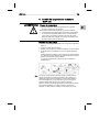
1
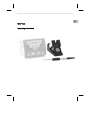
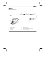
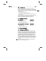
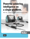
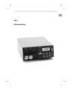
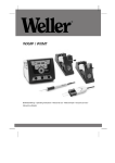
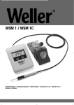
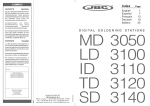
LV
EE
SL
SK
HU
PL
CZ
TR
GR
FI
DK
SV
NL
PT
ES
IT
Betriebsanleitung
LT
FR
WXP 120
EN
DE
WXP 120
WXP 120
Geräteübersicht
WXP 120
WDH 10
1.
Reinigungseinsatz
4.
LED Statusanzeige
2.
Lötspitze
5.
Temperaturbeständige antistatische Silikonleitung
3.
Spitzengriff
6.
Veriegelbarer Anschlußstecker
Inhaltsverzeichnis
1 Zu dieser Anleitung .................................................................... 3
DE
3-8
EN
WXP 120
Z Lesen Sie diese Anleitung und die beiliegenden
Sicherheitshinweise vor Inbetriebnahme des Lötkolbens
WXP 120 durch.
Z Bewahren Sie diese Anleitung so auf, dass sie für alle Benutzer
zugänglich ist.
1.1
Einzuhaltende Richtlinien
Der Weller Lötkolben WXP 120 entspricht der EGKonformitätserklärung gemäß den grundlegenden
Sicherheitsanforderungen der Richtlinien 2004/108/EG und
2006/95/EG.
1.2
Geltende Unterlagen
− Betriebsanleitung für Ihre Versorgungseinheit
− Betriebsanleitungen für WXP 120
2 Zu Ihrer Sicherheit
− Der Lötkolben WXP 120 wurde nach dem neuesten Stand der
Technik und anerkannten Sicherheitsregeln und -bestimmungen
entsprechend hergestellt.
− Bei Nichtbeachtung der beiliegenden Sicherheitsinformationen
und aufgeführten Warnhinweise besteht jedoch die Gefahr von
Personen- und Sachschäden.
− Geben Sie den WXP 120 Lötkolben nur zusammen mit dieser
Betriebsanleitung weiter.
IT
ES
PT
NL
SV
DK
FI
Diese Anleitung enthält wichtige Informationen, um den Lötkolben
WXP 120 sicher und sachgerecht in Betrieb zu nehmen, zu
bedienen, zu warten und einfache Störungen selbst zu beseitigen.
GR
Wir danken Ihnen für das mit dem Kauf des Weller Lötkolbens
WXP 120 erwiesene Vertrauen. Bei der Fertigung wurden strengste
Qualitätsanforderungen zugrunde gelegt, die eine einwandfreie
Funktion des Gerätes sicherstellen.
TR
Zu dieser Anleitung
CZ
1
PL
9 Garantie ..................................................................................... 8
HU
8 Entsorgung ................................................................................ 7
SK
7 Zubehör ..................................................................................... 7
SL
6 Wechsel der WXP 120 Lötspitzen ............................................. 6
EE
5 Inbetriebnahme des Gerätes ..................................................... 6
LV
4 Gerätebeschreibung .................................................................. 5
LT
3 Lieferumfang .............................................................................. 5
FR
2 Zu Ihrer Sicherheit ..................................................................... 3
4-8
WXP 120
− Der Hersteller ist nicht haftbar für Schäden, die aus einer
unsachgemäßen Verwendung des Werkzeugs oder unerlaubten
Veränderungen am Gerät entstehen.
2.1
Allgemeine
Hinweise
Umgang mit
Löt-/
Entlötspitzen
Beachten Sie bitte Folgendes:
− Legen Sie den Lötkolben WXP 120 immer in die vorgesehene
Sicherheitsablage.
− Entfernen Sie alle entzündbaren Objekte aus der Nähe des
heißen Lötwerkzeugs.
− Tragen Sie bei der Arbeit mit WXP 120 entsprechende
Schutzkleidung.
− Lassen Sie den heißen WXP 120 nie unbeaufsichtigt.
− Führen Sie keine Arbeiten an unter Spannung stehenden Teilen
aus.
− Antistatische Kunststoffe sind zur Verhinderung von statischen
Ladungen mit leitenden Füllstoffen versehen. Dadurch sind auch
die Isoliereigenschaften des Kunststoffes vermindert.
Führen Sie keine Arbeiten an unter Spannung stehenden Teilen
aus.
− Tragen Sie bei Löt- oder Entlötanwendungen immer einen
Augenschutz.
− Lesen und beachten Sie die Betriebsanleitung der jeweiligen
verwendeten Weller WX Versorgungseinheit
− Legen Sie heiße Löt- oder Entlötspitzen weder auf die
Arbeitsfläche oder auf Kunststoffflächen noch lassen Sie sie dort
zurück.
− Benetzen Sie beim ersten Aufheizen des Kolbens die verzinnten
Löt-/Entlötspitzen mit Lot, wodurch lagerbedingte Oxidschichten
oder Unreinheiten von den Löt- bzw. Entlötspitzen entfernt
werden.
− Vergewissern Sie sich, dass bei Arbeitsunterbrechungen
zwischen Löten und Entlöten sowie vor der Lagerung des
Gerätes die Löt-/Entlötspitzen gut benetzt sind.
− Verwenden Sie keine aggressiven Flussmittel.
− Immer darauf achten, dass die Löt-/Entlötspitzen
ordnungsgemäß sitzen.
− Wählen Sie die möglichst geringste Arbeitstemperatur.
− Wählen Sie die möglichst größte Löt-/Entlötspitzenform für die
Anwendung: ca. so groß wie das Lötpad.
− Benetzen Sie die Löt-/Entlötspitzen gut, um effiziente
Wärmeübertragung zwischen Löt-/Entlötspitzen und Lötpunkt zu
gewährleisten.
− Schalten Sie das System ab, wenn Sie das Löt-/Entlötwerkzeug
über längere Zeit nicht verwenden möchten.
− Benetzen Sie die Spitzen vor Ablegen des Löt-/Entlötwerkzeugs
in der Sicherheitsablage.
− Geben Sie das Lot direkt auf die Lötstelle, nicht auf die Löt-/
Entlötspitzen.
− Wenden Sie auf die Löt-/Entlötspitzen keine übermäßige Kraft
an.
− Immer darauf achten, dass der Lötkolben ordnungsgemäß in der
Sicherheitsablage liegt.
WXP 120
5-8
4 Gerätebeschreibung
4.1
Lötkolben WXP 120
Der Lötkolben WXP 120 von Weller darf nur mit den
Weller WX Versorgungseinheiten betrieben werden.
EN
FR
IT
ES
SV
DK
LT
Hinweis
LV
EE
Der WXP 120 Lötkolben zeichnet sich durch ein schnelles und
präzises Erreichen der Lötspitzentemperatur aus. Aufgrund seines
besonders leistungsfähigen 120 W Heizelementes wird ein
ausgezeichnetes dynamisches Verhalten erreicht. Zusammen mit
der schlanken Bauform und der kurzen Distanz vom Griff zur
Lötspitze findet dieser Lötkolben universellen Einsatz von extrem
feinen Lötarbeiten, bis hin zu solchen mit erhöhtem Wärmebedarf.
Der WXP 120 ist mit einer Nutzungserkennung ausgestattet und
kann bei Nichtgebrauch automatisch in Standbybetrieb bzw. Aus
geschaltet werden. Durch die LED Statusanzeige wird der jeweilige
Betriebszustand angezeigt. Das Einstellen der Standbytemperatur
sowie die Schaltzeiten entnehmen Sie bitte der Betriebsanleitung
der jeweils verwendeten WX Versorgungseinheit.
FI
T0051512199
T0058703153
GR
− WDH 10 Sicherheitsablage
− Steckverbinder für Fußplatte
− Betriebsanleitung WDC 2
TR
T0052920299:
CZ
Zusätzlich beim WXP 120 Lötset
PL
T0052920199:
− WXP 120 Lötkolben,
T0052920199
− XT B Meißelspitze 2,4 X 0,8 mm T0054470400
− Betriebsanleitung WXP 120
HU
WXP 120 verpackt
SK
3 Lieferumfang
NL
PT
Der Hersteller übernimmt keine Haftung für Schäden, die aus
unsachgemäßem, nicht dem in der Betriebsanleitung beschriebenen
Gebrauch oder unerlaubten Änderungen am Gerät resultieren.
DE
Bestimmungsgemäßer Gebrauch
SL
2.2
Verwenden Sie den WXP 120 Lötkolben ausschließlich für den in
der Betriebsanleitung bezüglich Lösen, Verstauung und Ablage von
elektronischen Bauteilen angegebenen Zweck unter den hier
beschriebenen Bedingungen. Der bestimmungsgemäße Gebrauch
des Lötkolbens WXP 120 beinhaltet auch, dass
− Sie diese Anleitung beachten,
− Sie alle weiteren Begleitunterlagen beachten,
− Sie die nationalen Unfallverhütungsvorschriften am Einsatzort
beachten.
6-8
WXP 120
4.2
Technische Daten
Temperaturbereich
100°C - 450°C (212°F - 850°F)
Werkzeugkabel
Silikonkautschuk, hitzebeständig
Heizelement
Integriertes Heizdrahtelement
Temperatursensor
Platinsensor
Heizleistung
120 W
Spannung (Heizung)
24 V
Aufheizzeit
(ca.) 14s (50°C auf 380°C)
(120°F auf 660°F)
Anschluss
6 poliger St. verpolungssicher mit
Verriegelung
Gewicht
42 g incl. Spitze ohne Kabel
Spitzentyp
XT-Baureihe
Versorgungseinheit
Weller WX Stationen
5 Inbetriebnahme des Gerätes
WARNUNG! Verbrennungsgefahr
Die Lötspitzen vom Lötkolben werden beim
Löt-/Entlötvorgang sehr heiß.
Bei Berührung der Spitzen besteht Verbrennungsgefahr.
Z Berühren Sie nicht die heißen Lötspitzen und halten Sie
entzündbare Objekte fern.
1. Den Lötkolben WXP 120 vorsichtig auspacken.
2. Den Lötkolben in der Sicherheitsablage WDH 10 ablegen.
3. Den Anschlussstecker (6) an der Versorgungseinheit
anschließen und durch Drehen im Uhrzeigersinn verriegeln.
4. Überprüfen Sie, ob die Netzspannung mit der Spannungsangabe
auf dem Typenschild der WX Versorgungseinheit übereinstimmt.
5. Die Versorgungseinheit einschalten und die gewünschte
Temperatur einstellen.
6. Hat das Werkzeug die gewünschte Temperatur erreicht, leuchtet
die LED Status Anzeige (4) dauernd. Die Lötspitze mit Lot
benetzen.
6 Wechsel der WXP 120 Lötspitzen
WARNUNG! Verbrennungsgefahr
Die Lötspitze wird bei Löt- und Entlötvorgängen sehr heiß.
Bei Berührung der Lötspitze besteht Verbrennungsgefahr.
Z Das Lötwerkzeug muss in ausgeschaltetem Zustand
mindestens 3 Minuten in der Sicherheitsablage (WDH 10)
verbleiben, bis die Lötspitze abgekühlt ist. LED Status
Anzeige (4) muss Aus sein. Lötspitzen dürfen nur gewechselt
werden, wenn sie kalt sind.
WXP 120
7-8
5. Lötspitze mit der Spitze nach vorne in Spitzenhalter einlegen.
Spitzenhalter zusammen mit der Lötspitze über das Heizelement
schieben und mit Rechtsdrehung festdrehen.
6. Netzschalter der Versorgungseinheit einschalten und die
gewünschte Temperatur einstellen.
Bestell-Nr.
Beschreibung
T0052920199
WXP 120 Lötkolben
T0051512199
Sicherheitsablage WDH 10
T0051384199
Spiralwolle für Reinigungseinsatz für WDC 2
8 Entsorgung
Entsorgen Sie ausgetauschte Geräteteile, Filter oder alte Geräte
gemäß den Vorschriften Ihres Landes.
EN
SV
DK
FI
SK
Ersatzteile und Zubehör für WXP 120
SL
7.2
EE
Siehe Tabelle XT Lötspitzen für Lötkolben WXP 120 am Ende dieser
Anleitung und auf www.weller.eu
HU
XT Lötspitzen für den Lötkolben WXP 120
LV
7.1
PL
7 Zubehör
GR
Einsetzen einer neuen Lötspitze
TR
Die Wärmeübertragungsflächen von Lötspitze und Heizkörper
sauber halten. Das Heizelement darf nicht mit Lötzinn in Berührung
kommen.
CZ
Die Lötspitze / Messspitze nicht auf dem Reinigungsschwamm oder
Kunststoffoberflächen ablegen bzw. abkühlen. Bei der Verwendung
von mehreren Lötspitzentypen, wird empfohlen die Lötspitze (2) und
den Spitzenhalter (3) zusammen in dem Wechselsystem zu
verwenden (siehe 3 Bild oben).
LT
Hinweis
NL
PT
ES
IT
4. Lötkolben mit der Spitze leicht nach unten halten.
Lötkolben am hinteren Griffteil (4) fest halten und
Spitzenhalter (3) mit Linksdrehung abschrauben
Spitzenhalter (3) nach vorne abziehen
Lötspitze (2) befindet sich nun lose im Spitzenhalter (3)
FR
1. Lötwerkzeug in die Sicherheitsablage WDH 10 legen.
2. Netzschalter der Versorgungseinheit ausschalten.
3. Drei Minuten warten, bis die Lötspitze abgekühlt ist.
DE
Auswechseln einer verbrauchten Spitze
8-8
9 Garantie
WXP 120
Die Mängelansprüche des Käufers verjähren nach einem Jahr ab
Ablieferung an ihn. Dies gilt nicht für Rückgriffsansprüche des
Käufers nach §§ 478, 479 BGB.
Aus einer von uns abgegebenen Garantie haften wir nur bei
Ansprüchen, wenn die Beschaffenheits- oder Haltbarkeitsgarantie
von uns schriftlich und unter Verwendung des Begriffs „Garantie“
abgegeben worden ist.
Technische Änderungen vorbehalten!
Die aktualisierten Betriebsanleitungen finden Sie unter
www.weller.eu.
LV
EE
SL
SK
HU
PL
CZ
TR
GR
FI
DK
SV
NL
PT
ES
IT
Operating Instructions
LT
FR
WXP 120
EN
DE
WXP 120
WXP 120
Hardware Overview
WXP 120
WDH 10
1.
Cleaning element
4.
LED status indicator
2.
Soldering tip
5.
Heat-resistant antistatic silicon cable
3.
Tip handle
6.
Lockable connector plug
3-8
Table of Contents
DE
WXP 120
Z Read these instructions and the accompanying safety information
carefully before starting up the device and starting work with the
WXP 120 soldering iron.
Z Keep these instructions in a safe place and so that they are
easily accessible to all users.
1.1
Directives taken into consideration
The Weller WXP 120 soldering iron conforms to the specifications of
the EC Declaration of Conformity as defined by Directives
2004/108/EC and 2006/95/EC.
1.2
Applicable documents
− Operating instructions for your supply unit
− Operating instructions for WXP 120
2 For your safety
− The WXP 120 soldering iron has been manufactured in
accordance with the current state of the art and recognised safety
rules and regulations. There is nevertheless the risk of personal
injury and damage to property if you fail to observe the safety
information set out in the accompanying booklet and the warnings
given in these instructions.
FR
IT
ES
PT
NL
SV
DK
FI
These instructions contain important information which will help you
to start up, operate and service the WXP 120 soldering iron safely
and correctly as well as to eliminate simple faults or malfunctions
yourselves.
GR
Thank you for the confidence you have shown in buying the Weller
WXP 120 soldering iron. The device has been manufactured in
accordance with the most rigorous quality standards, which ensure
that it operates perfectly.
TR
1 About these instructions
CZ
9 Warranty .................................................................................... 8
PL
8 Disposal ..................................................................................... 7
HU
7 Accessories ............................................................................... 7
SK
6 Replacing the WXP 120 soldering tips ...................................... 6
SL
5 Commissioning the device ......................................................... 6
EE
4 Device description ..................................................................... 5
LV
3 Included in delivery .................................................................... 5
LT
2 For your safety ........................................................................... 3
EN
1 About these instructions ............................................................ 3
4-8
WXP 120
− Always pass on the WXP 120 soldering iron to third parties
together with these operating instructions.
− The manufacturer accepts no liability for improper use of the tool
or for unauthorised modifications.
2.1
General
information
Handling
soldering/de
soldering
tips
Please observe the following guidelines:
− Always place the WXP 120 soldering iron in the intended safety
rest.
− Remove all inflammable articles from around the hot soldering
iron.
− Always wear suitable protective clothing when using the
WXP 120.
− Never leave a hot WXP 120 unattended.
− Do not work on electrically live parts.
− Antistatic plastics are provided with conductive fillers to prevent
the build-up of static charge. This also reduces the insulating
properties of the plastic.
Do not work on electrically live parts.
− Always wear eye protection when working with soldering and
desoldering applications.
− Read and follow the operating instructions for the Weller WX
supply unit.
− Do not place or leave hot soldering/desoldering tips on the
worktop or on plastic surfaces.
− Wet the tinned soldering/desoldering tips with solder once they
have heated up in order to remove oxide layers that form during
storage or contamination from the soldering/desoldering tips.
− Ensure the soldering/desoldering tips are well wetted during
intervals between soldering and desoldering and prior to storage
of the device.
− Do not use aggressive fluxing agents.
− Always make sure that the soldering/desoldering tips are
properly seated.
− Select the lowest possible working temperature.
− Select the largest possible soldering/desoldering tip shape for
the application (roughly as large as the soldering pad).
− Wet the soldering/desoldering tips well to ensure efficient heat
transfer between the soldering/desoldering tips and the soldering
spot.
− Switch off the system if you do not intend to use the
soldering/desoldering tool for prolonged periods.
− Wet the tips before placing the soldering/desoldering tool in the
safety rest.
− Apply the solder directly at the soldering point, not on the
soldering/
desoldering tips.
− Do not apply excessive force to the soldering/desoldering tips.
− Always make sure that the soldering iron is placed properly in the
safety rest.
WXP 120
5-8
4.1
Soldering iron WXP 120
The WXP 120 soldering iron is characterised by fast and precise
achievement of the soldering tip temperature. A highly powerful
120 W heater element provides excellent dynamic performance.
Thanks to its slim-line design and the extremely short distance from
the handle to the tip, this soldering iron can be used for general
purposes from precision soldering to high-temperature soldering.
The WXP 120 is equipped with a usage detector and can be
automatically switched to standby mode or switched off when not in
use. The operating status is indicated by the status indicator LED.
For directions for setting the standby temperature and the switching
times, please refer to the operating instructions of the WX supply
unit in use.
Note
The WXP 120 soldering iron by Weller may only be operated
together with Weller WX supply units.
EN
FR
IT
ES
SV
DK
FI
GR
4 Device description
TR
T0051512199
T0058703153
CZ
− WDH 10 safety rest
− Sole plate connector
− Operating instructions of WDC 2
PL
T0052920299:
HU
Also included in WXP 120 soldering set
SK
T0052920199
T0054470400
SL
T0052920199:
− Soldering iron WXP 120,
− XT B chisel tip 2.4 X 0.8 mm
− Operating instructions of WXP 120
EE
WXP 120 (packed)
LV
3 Included in delivery
NL
PT
The manufacturer accepts no liability for any damage resulting from
failure to use the device in compliance with these operating
instructions or unauthorised modifications to the device.
DE
Intended use
LT
2.2
Use the WXP 120 soldering iron exclusively for the purpose
indicated in the operating instructions of releasing, accommodating
and depositing electronic components under the conditions specified
herein. Intended use of the WXP 120 soldering iron also includes the
requirement that you
− adhere to these instructions,
− observe all other accompanying documents,
− comply with national accident prevention guidelines applicable at
the place of use.
6-8
WXP 120
4.2
Technical data
Temperature range
100°C - 450°C (212°F - 850°F)
Tool cable
Silicone rubber, heat resistant
Heating element
Integrated heating wire element
Temperature sensor
Platinum sensor
Heating output
120 W
Voltage (heater)
24 V
Heat-up time
(approx.) 14s (50°C to 380°C)
(120°F to 660°F)
Connection
6 pin connector, polarity protected with lock
Weight
42 g incl. cordless tip
Tip type
XT series
Supply unit
Weller WX stations
5 Commissioning the device
WARNING! Risk of burns
The soldering tips of soldering irons become very hot during
soldering and desoldering processes.
There is a risk of burns from touching the tips.
Z Do not touch the hot soldering tips and keep them away from
inflammable objects.
1. Carefully unpack the WXP 120 soldering iron.
2. Place the soldering iron into safety rest WDH 10.
3. Insert the connecting plug (6) into the power supply socket and
lock it by turning it clockwise.
4. Check to make sure that the mains voltage matches the voltage
specified on the rating plate of the WX supply unit.
5. Switch on the supply unit and set the required temperature.
6. If the tool has not reached the required temperature, the status
indicator LED (4) will be lit continuously. Wet the soldering tip
with solder.
6 Replacing the WXP 120 soldering tips
WARNING! Risk of burns
The soldering tip becomes hot during soldering and desoldering
processes.
There is a risk of burns from touching the soldering tip.
Z The soldering tool must be switched off and stand at least
3 min. in the safety rest (WDH 10) until the soldering tip has
cooled off. The status indicator LED (4) must be OFF. Only
replace the soldering tips when they are cold.
WXP 120
7-8
XT soldering tips for the WXP 120 soldering
iron
See the table XT soldering tips for WXP 120 soldering iron in the
section in the back and at www.weller.eu
7.2
Replacement parts and accessories for
WXP 120
Order no.
Description
T0052920199
WXP 120 soldering iron
T0051512199
WDH 10 safety rest
T0051384199
Metal wool for cleaning element for WDC 2
8 Disposal
Dispose of replaced equipment parts, filters or old devices in
accordance with the rules and regulations applicable in your country.
EN
DK
FI
GR
TR
CZ
PL
7.1
HU
7 Accessories
SK
5. Place the soldering tip into the tip receptacle with the tip pointing
forwards. Push the tip receptacle together with the soldering tip
over the heating element and rotate clockwise to tighten.
6. Switch on the supply unit and set the required temperature.
SL
Inserting a new soldering tip
EE
Keep the heat transfer surfaces of the soldering tip and heating
element clean. The heating element must not come into contact with
soldering tin.
LV
Do not place or leave the hot soldering tip or probe tip on the
cleaning sponge or on plastic surfaces. When using multiple types
of soldering tip, it is recommended that the soldering tip (2) and tip
receptacle (3) be used together in the changing system (see figure
above).
LT
Note
SV
NL
PT
ES
IT
4. Hold the soldering iron with the tip pointing downward.
Hold the soldering iron by the rear handle (4) and
unscrew the tip receptacle (3) by twisting it anticlockwise
Pull off the receptacle (3) forwards
The soldering tip (2) is now loose in the receptacle (3).
FR
1. Place the soldering tool in the WDH 10 safety rest.
2. Switch off the supply unit.
3. Wait three minutes until the soldering tip has cooled off.
DE
Replacing a used soldering tip
8-8
9 Warranty
WXP 120
Claims by the buyer for physical defects are time-barred after a
period of one year from delivery to the buyer. This does not apply to
claims by the buyer for indemnification in accordance with §§ 478,
479 BGB (German Federal Law Gazette).
We shall only be liable for claims arising from a warranty furnished
by us if the quality or durability warranty has been furnished by use
in writing and using the term "Warranty“.
In addition, for the USA and Canada:
Cooper Tools warrants to the original purchaser and any subsequent
owner (“Buyer”) that Weller soldering and desoldering products will
be free from defects in material and workmanship for a period of one
year from date of purchase, provided that no warranty is made with
respect to products which have been altered, subjected to abuse or
improperly used, installed or repaired. Use of non-Cooper Tools
components will void this warranty if a non-Cooper Tools component
is defective (or is the source of the defect). Cooper Tools will repair
or replace products found to be defective not caused by a part,
component or accessory manufactured by another company, during
the warranty period. Contact Cooper Tools with dated proof of
purchase and return to Apex Tool Group, LLC., 14600 York Rd. Suit
A, Sparks, MD 21152. All costs of transportation and reinstallation
shall be borne by the Buyer.
IN NO EVENT SHALL COOPER TOOLS BE LIABLE FOR
INCIDENTAL OR CONSEQUENTIAL DAMAGES. COOPER TOOLS
LIABILITY FOR ANY CLAIMS ARISING OUT OF THIS WARRANTY
SHALL NOT EXCEED THE PURCHASE PRICE OF THE
PRODUCT.
THE PERIOD OF ALL IMPLIED WARRANTIES APPLICABLE TO
THIS PRODUCT INCLUDING ANY IMPLIED WARRANTY OF
MERCHANTABILITY OR FITNESS, OR FITNESS FOR A
PARTICULAR PURPOSE IS LIMITED TO 12 MONTHS FROM THE
DATE OF PURCHASE BY THE USER.
Some states do not allow the exclusion or limitation of incidental or
consequential damages, so the above limitation or exclusion may
not apply to you. Some states do not allow limitation on how long an
implied warranty lasts, so the above limitation may not apply to you.
This warranty gives you specific legal rights, and you may also have
other rights, which vary from state to state.
Subject to technical alterations and amendments!
Updated operating instructions are available for download at
www.weller.eu.
LV
EE
SL
SK
HU
PL
CZ
TR
GR
FI
DK
SV
NL
PT
ES
IT
Manual de uso
LT
ES
WXP 120
EN
DE
WXP 120
WXP 120
Componentes principales del aparato
WXP 120
WDH 10
1.
Limpiador
4.
LED de estado
2.
Punta de soldadura
5.
Cable de silicona antiestático y termorresistente
3.
Empuñadura de la punta
6.
Clavija de conexión con mecanismo de bloqueo
3-8
Índice
DE
WXP 120
Este manual de uso contiene información importante para poder
poner en marcha y manejar de forma segura y adecuada el lápiz de
soldadura WXP 120, así como para realizar tareas de
mantenimiento e incluso reparar pequeñas averías.
Z Lea atentamente estas instrucciones de uso y las indicaciones
de seguridad adjuntas antes de poner en funcionamiento el lápiz
de soldadura WXP 120.
Z Mantenga este manual de uso en un lugar al que puedan
acceder todos los usuarios del aparato.
1.1
Directivas que tener en cuenta
El lápiz de soldadura WXP 120 de Weller dispone de la Declaración
de Conformidad CE que certifica el cumplimiento de los requisitos
básicos de seguridad contemplados en las Directivas 2004/108/CE y
2006/95/CE.
1.2
Documentos aplicables
− Manual de instrucciones para la unidad de alimentación
− Manual de uso para el WXP 120
2 Acerca de la seguridad
− El lápiz de soldadura WXP 120 ha sido fabricado conforme a los
últimos avances tecnológicos y las normativas y disposiciones de
seguridad reconocidas. No obstante, existe riesgo de daños
personales y daños a la propiedad si se hace caso omiso a la
información de seguridad establecida en el folleto adjunto que
acompaña a este manual de instrucciones y a las advertencias
mencionadas al respecto.
ES
IT
ES
PT
NL
SV
DK
FI
Le agradecemos la confianza depositada en nosotros al comprar el
lápiz de soldadura WXP 120 de Weller. La fabricación de este
aparato está sometida a los más rigurosos controles de calidad para
garantizar un perfecto funcionamiento del mismo.
GR
Acerca de estas instrucciones
TR
1
CZ
9 Garantía ..................................................................................... 8
PL
8 Eliminación de residuos ............................................................. 8
HU
7 Accesorios ................................................................................. 8
SK
6 Cambio de las puntas de soldadura WXP 120 ......................... 7
SL
5 Puesta en servicio del aparato .................................................. 6
EE
4 Descripción del aparato ............................................................. 5
LV
3 Piezas suministradas ................................................................. 5
LT
2 Acerca de la seguridad .............................................................. 3
EN
1 Acerca de estas instrucciones ................................................... 3
4-8
WXP 120
− Entregue siempre el lápiz de soldadura WXP 120 a terceros junto
con este manual de uso.
− El fabricante no asumirá ningún daño resultante del uso indebido
de la herramienta ni de modificaciones no autorizadas.
2.1
Indicaciones
generales
Manejo de
las puntas
de
soldadura /
desoldadura
Tener en cuenta lo siguiente:
− Colocar siempre el lápiz de soldadura WXP 120 en el soporte de
seguridad previsto a tal efecto.
− Retirar todos los objetos inflamables de las proximidades de la
herramienta de soldadura.
− Llevar siempre una indumentaria protectora adecuada al utilizar
el WXP 120.
− Mantener siempre vigilado el WXP 120 caliente.
− No trabajar en piezas sometidas a tensión.
− Los materiales plásticos antiestáticos contienen sustancias de
relleno conductoras para impedir que se puedan producir cargas
estáticas. De esta forma también quedan mermadas las
propiedades aislantes del material plástico.
No trabajar en piezas sometidas a tensión.
− Llevar siempre protección ocular al trabajar con aplicaciones de
soldadura y desoldadura.
− Leer y respetar las indicaciones recogidas en el manual de uso
de la unidad de alimentación Weller WX
− No colocar ni dejar las puntas de soldadura/desoldadura
calientes sobre la esponja limpiadora ni sobre superficies de
plástico.
− Recubrir las puntas de soldadura/desoldadura estañadas al
calentar el soldador por primera vez, así se eliminarán todas las
películas de óxido o impurezas de las puntas de
soldadura/desoldadura que se hayan acumulado durante el
almacenamiento.
− Durante las interrupciones de la soldadura/desoldadura y antes
de almacenar la herramienta, asegurarse de que las puntas de
soldadura/desoldadura estén bien recubiertas.
− No utilizar fundentes agresivos.
− Asegurarse siempre de que las puntas de
soldadura/desoldadura estén colocadas correctamente.
− Seleccionar una temperatura de trabajo lo más baja posible.
− Seleccionar unas puntas de soldadura/desoldadura lo más
largas posibles para la aplicación: aprox. de la longitud de la
placa de soldar.
− Recubrir bien las puntas de soldadura/desoldadura para
asegurarse una transferencia de calor eficiente entre las puntas
de soldadura/desoldadura y el punto de soldadura.
− Desconectar el sistema si no está previsto utilizar la herramienta
de soldadura/desoldadura durante largos periodos de tiempo.
− Recubrir las puntas antes de colocar la herramienta de
soldadura/desoldadura en el soporte de seguridad.
− Soldar directamente en el punto de soldadura, no en las puntas
de soldadura/desoldadura.
− No someter las puntas de soldadura/desoldadura a fuerzas
físicas.
El fabricante no asumirá ningún daño resultante del uso incorrecto
de este aparato en cumplimiento con el presente manual de
instrucciones o de las modificaciones no autorizadas en el aparato.
4 Descripción del aparato
4.1
Lápiz de soldadura WXP 120
El lápiz de soldadura WXP 120 se distingue por su rapidez y
precisión para alcanzar la temperatura deseada. La extraordinaria
potencia (120 W) de su elemento calefactor le proporciona un
comportamiento dinámico excelente. Su reducido diseño y la corta
distancia entre el mango y la punta permiten utilizar este lápiz de
soldar de forma universal, desde los trabajos más precisos hasta
aquellos que requieran mayor temperatura. El WXP 120 está
equipado con un sistema de detección de uso que desconecta
automáticamente el aparato —o lo pone en modo de inactividad—
cuando no se está utilizando. El LED de estado señala el estado de
funcionamiento del aparato. La información relativa al ajuste de
temperatura para el modo de inactividad, así como de los tiempos
de desconexión, aparece recogida en el manual de uso de la unidad
de alimentación WX.
Nota
El lápiz de soldadura WXP 120 de Weller debe utilizarse
únicamente con las unidades de alimentación Weller WX.
EN
ES
FI
GR
TR
CZ
T0051512199
T0058703153
PL
T0052920299:
HU
− Soporte de seguridad WDH 10
− Acoplamiento para la base
− Manual de uso para WDC 2
SK
Elementos adicionales para el juego de
soldadura WXP 120
SL
T0052920199
T0054470400
EE
T0052920199:
− Lápiz de soldadura WXP 120,
− Punta de cincel XT B de 2,4 X 0,8 mm
− Manual de uso para WXP 120
LV
WXP 120 embalado
DK
SV
3 Piezas suministradas
IT
Emplear el lápiz de soldadura WXP 120 exclusivamente para el
propósito indicado en el manual de uso en lo referente a la
liberación, alojamiento y fijación de componentes electrónicos bajo
las condiciones especificadas aquí. Dentro del uso previsto para el
lápiz de soldadura WXP 120 también se incluye lo siguiente:
− Seguir las instrucciones de este manual.
− Seguir las instrucciones de todos los documentos que acompañan
al aparato.
− Cumplir las normas de prevención de accidentes laborales
vigentes en el país de uso.
ES
Uso reglamentario
LT
2.2
PT
− Asegurarse siempre de que el lápiz de soldadura está colocado
correctamente en el soporte de seguridad.
DE
5-8
NL
WXP 120
6-8
WXP 120
4.2
Datos técnicos
Rango de temperatura 100 °C – 450 °C (212 °F – 850 °F)
Cable de la
herramienta
Caucho de silicona, resistente al fuego
Elemento calefactor
Alambre de calefacción integrado
Sensor de
temperatura
Sensor de platino
Potencia de
calentamiento
120 W
Tensión de
calentamiento
24 V
Tiempo de
calentamiento
(aprox.) 14 s (50 °C a 380 °C)
(120 °F a 660 °F)
Conector
Conector de 6 polos con protección
contra polaridad inversa y mecanismo de
bloqueo
Peso de la
herramienta
42 g incluida punta sin cable
Tipo de punta
Serie XT
Unidad de
alimentación
Estaciones Weller WX
5 Puesta en servicio del aparato
¡ADVERTENCIA! Riesgo de quemaduras
Las puntas del lápiz de soldadura alcanzan temperaturas muy
elevadas durante los trabajos de soldadura/desoldadura.
Existe riesgo de quemaduras al tocar las puntas de
soldadura/desoldadura.
Z No toque las puntas de soldadura calientes y manténgalas
siempre alejadas de objetos inflamables.
1. Desembalar con cuidado el lápiz de soldadura WXP 120.
2. Colocar el lápiz de soldadura en el soporte de seguridad
WDH 10.
3. Insertar la clavija de conexión (6) en la unidad de alimentación
corriente y bloquearla girándola en sentido horario.
4. Comprobar si la tensión de la red coincide con los datos de la
placa de identificación de la unidad de alimentación WX.
5. Encender la unidad de alimentación y ajustar la temperatura
deseada.
6. Una vez que la herramienta ha alcanzado la temperatura
deseada, el LED de estado (4) se ilumina de forma permanente.
Estañar la punta de soldadura.
Extracción de la punta antigua
1. Colocar la herramienta de soldadura en el soporte de seguridad
WDH 10.
2. Apagar la unidad de alimentación.
3. Esperar 3 min hasta que la punta de soldadura se haya enfriado.
EN
ES
IT
ES
PT
SK
SL
EE
Mantener siempre limpias las superficies de transmisión térmica de
las puntas de soldadura y el cuerpo calefactor. El elemento
calefactor no debe entrar en contacto con el estaño para soldar.
LV
No colocar ni dejar enfriar la punta de soldar (o medir) sobre la
esponja de limpieza o superficies de plástico. Si se trabaja con
distintos tipos de puntas de soldadura, se recomienda utilizar la
punta de soldadura (2) y el portapuntas (3) juntos para que los
cambios resulten más rápidos (ver 3 figuras superiores).
LT
Nota
HU
PL
CZ
TR
4. Sostener el lápiz de soldadura con la punta ligeramente hacia
abajo.
Sujetar firmemente el lápiz por la zona de la empuñadura trasera
(4) y desenroscar el portapuntas (3) girándolo hacia la izquierda
Extraer el portapuntas (3) hacia delante
La punta de soldadura (2) se encuentra ahora suelta en el
portapuntas (3)
NL
Z La herramienta de soldadura debe permanecer desconectada
en el soporte de seguridad (WDH 10) por lo menos durante
3 min. para que la punta de soldadura se enfríe. El LED de
estado (4) debe estar apagado. Las puntas de soldadura solo
se deben cambiar cuando estén frías.
SV
La punta de soldadura alcanza temperaturas muy elevadas
durante la soldadura y desoldadura.
Existe riesgo de quemaduras al tocar la punta de soldadura .
DK
¡ADVERTENCIA! Riesgo de quemaduras
FI
6 Cambio de las puntas de soldadura
WXP 120
DE
7-8
GR
WXP 120
8-8
WXP 120
Instalación de una punta de soldadura nueva
5. Introducir la punta de soldadura en el portapuntas (con la punta
hacia delante). Colocar el portapuntas junto con la punta de
soldadura en el elemento calefactor y apretarlo girándolo hacia la
derecha.
6. Encender la unidad de alimentación y ajustar la temperatura
deseada.
7 Accesorios
7.1
Puntas de soldadura XT para el lápiz de
soldadura WXP 120
Ver la tabla de puntas de soldadura XT para lápiz de soldadura
WXP 120 al final de este manual y en www.weller.eu
7.2
Piezas de repuesto y accesorios para el
WXP120
N.º pedido
Descripción
T0052920199
Lápiz de soldadura WXP 120
T0051512199
Soporte de seguridad WDH 10
T0051384199
Lana de acero para útil limpiador WDC 2
8 Eliminación de residuos
Eliminar las piezas sustituidas del equipo, filtros u otros aparatos
antiguos según las normas y regulaciones aplicables en el país
correspondiente.
9 Garantía
Las reclamaciones por parte del comprador en cuanto a defectos
físicos se limitan a un periodo de un año a partir de la fecha de
entrega al comprador. Solo válido para los derechos del comprador
según el art. §§ 478, 479 BGB (código civil alemán).
Nosotros asumiremos solo aquellas reclamaciones relacionadas con
la garantía que hemos concedido, siempre y cuando la garantía de
calidad y durabilidad haya sido concedida de forma escrita y con
mención expresa del término "Garantía“.
¡Reservado el derecho a realizar modificaciones técnicas!
Encontrará los manuales de instrucciones actualizados en
www.weller.eu.
WP120:WP80_H5.qxd 16.09.10 09:05 Seite 21
Soldering Tips
XT- Spitzen für WP 120
Soldering Tips for WP 120
Bestell-Nr.
Order-No
Modell Beschreibung.
Model Description
Breite A
Width A
Dicke B Länge C
Length B Length C
T005 44 701 99 XT AL
Meisselform
Chisel
1,6 mm
0.063 in.
1,0 mm 39 mm
0.039 in. 1.535 in
T005 44 702 99 XT M
Meisselform
Chisel
3,2 mm
0.126 in.
1,2 mm 39 mm
0.047 in. 1.535 in.
T005 44 703 99 XT A
Meisselform
Chisel
1,6 mm
0.063 in.
0,7 mm 36 mm
0.028 in. 1.420 in
T005 44 704 99 XT B
Meisselform
Chisel
2,4 mm
0.094 in.
0,8 mm 35 mm
0.031 in. 1.377 in.
T005 44 705 99 XT C
Meisselform
Chisel
3,2 mm
0.126 in.
0,8 mm 35 mm
0.031 in. 1.377 in.
T005 44 706 99 XT D
Meisselform
Chisel
4,6 mm
0.18 in.
0,8 mm 34,5 mm
0.031 in. 1.358 in.
T005 44 707 99 XT E
Meisselform
Chisel
5,9 mm
0.232 in.
1,2 mm 34,5 mm
0.047 in. 1.358 in.
T005 44 708 99 XT AA
60° Lötspitze
60° tip bulk
Ø 1,6 mm
Ø 0.063 in.
T005 44 709 99 XT BB
45° Lötspitze
45° tip bulk
Ø 2,4 mm
Ø 0.094 in.
T005 44 710 99 XT CC
45° Lötspitze
45° tip bulk
Ø 3,2 mm
Ø 0.126 in.
WP120:WP80_H5.qxd 16.09.10 09:06 Seite 22
Soldering Tips
Bestell-Nr.
Order-No
Modell Beschreibung.
Model Description
Breite A
Width A
Dicke B Länge C
Length B Length C
T005 44 711 99 XT KN
60° Lötspitze
60° tip bulk
Ø 2,0 mm
Ø 0.078 in.
T005 44 712 99 XT GW
Lötspitze
Chisel
2,3 mm/3,2 mm
0.091 in. / 0.126 in.
T005 44 714 99 XT O
Rundform
Round chisel
Ø 1,0 mm
Ø 0.039 in.
T005 44 715 99 XT BS
Rundform
Round chisel
Ø 2,4 mm
Ø 0.095 in.
T005 44 716 99 XT CS
Rundform
Round chisel
Ø 3,2 mm
Ø 0.126 in.
T005 44 717 99 XT DS
Rundform
Round chisel
Ø 5,0 mm
Ø 0.197 in.
T005 44 718 99 XT F
30° Rundf. abgeschr. Ø 1,2 mm
30° Round sloped chisel Ø 0.047 in.
T005 44 719 99 XT Adapter M4
T005 44 720 99 XT Adapter M5
T005 44 721 99 XT D45 45° Solar Lötspitze
45° Solar chisel
5,0 mm
0.197 in.
WP120:WP80_H5.qxd 16.09.10 09:08 Seite 23
Soldering Tips
Bestell-Nr.
Order-No
Modell Beschreibung.
Model Description
T005 44 722 99 XT Messspitze
XT Measuring tip
Breite A
Width A
5,0 mm
0.197 in.
Dicke B Länge C
Length B Length C
WXP 120_tips:WP80_H5.qxd 16.09.10 09:12 Seite 4
Exploded Drawing