1
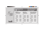
PumpenAntrieb
Pump
drive
Moteur de
pompe
Schutzgrad IP 30
Protection rating IP 30
Classe de protection IP 30
ISM 404
ISM 404
ISM 404
Für Pumpenköpfe:
Pro 280 / Pro 281
Pro 380 / Pro 381
360 / 380 / 380 AD
CA 4 / CA 8 / CA 12
FMI Q0 / Q1 / Q2 / Q3
Easy-Load
Standard
Quickload
MS/CA 4-12 / MS/CA 8-6
PTFE Tube 2 mm / 4 mm
SB 2V / 3V
WM 5
For pump heads:
Pro 280 / Pro 281
Pro 380 / Pro 381
360 / 380 / 380 AD
CA 4 / CA 8 / CA 12
FMI Q0 / Q1 / Q2 / Q3
Easy-Load
Standard
Quickload
MS/CA 4-12 / MS/CA 8-6
PTFE Tube 2 mm / 4 mm
SB 2V / 3V
WM 5
Pour têtes de pompe:
PPro 280 / Pro 281
Pro 380 / Pro 381
360 / 380 / 380 AD
CA 4 / CA 8 / CA 12
FMI Q0 / Q1 / Q2 / Q3
Easy-Load
Standard
Quickload
MS/CA 4-12 / MS/CA 8-6
PTFE Tube 2 mm / 4 mm
SB 2V / 3V
WM 5
Deutsch
English
Français
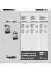
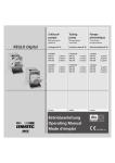
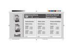
Mikroprozessorgesteuert
MCP Standard
Microprocessor
controlled
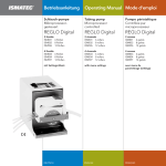
Betriebsanleitung
Operating Manual
Mode d‘emploi
MCP Standard/ISMATEC SA/12.06.07/CB/GP
Commandé par
microprocesseur
12.06.07
CB/GP
1
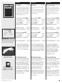
Inhaltsverzeichnis
2
Contents
Sommaire
Sicherheitsvorkehrungen
4
Safety precautions
4
Mesures de précaution
4
Garantiebestimmungen
6
Warranty terms
6
Conditions de garantie
6
Produkt
Geräterückwand
8
9
Product
Rear panel
8
9
Produit
Tableau arrière
8
9
Netzspannung
Spannungsumschaltung
Sicherungen wechseln
9
10
10
Mains voltage
Voltage setting
Changing the fuses
9
10
10
Tension d’alimentation
Commutation de la tension
Remplacement des fusibles
9
10
10
Inbetriebnahme
Bedienungspanel
11
12
Starting the pump
Operating panel
11
12
11
12
Start-Information
Parameter auf
Default-Werte setzen
13
13
14
Start-up information
Resetting the parameters to
the default values
14
Mise en route
Tableau de commande
Informations de
mise en route
Remise des paramètres à
leurs valeurs par défaut
Steuertasten
15
Control keys
15
Touches de commande
15
Pumpenkopf-Identifikation
16
Pump head identification
16
Schlauch iØ
oder Hubwinkel eingeben
17
Entering the tubing i.d.
or stroke angle
17
Identification de la tête
de pompe
Saisie du diamètre de tube
ou de l’angle de course
Programmwahl
Total-Volumen
18
18
Program selection
Total volume
18
18
Sélection du programme
Volume total
18
18
Pumpen
nach Drehzahl
nach Fließrate
19
20
Pumping
by drive speed
by flow rate
19
20
Pompage selon
le nombre de tours
le débit
19
20
Fließrate kalibrieren
21
Calibrating the flow rate
21
Calibration du débit
21
Dosieren
nach Zeit
nach Volumen
22
23
Dispensing
by time
by volume
22
23
Dosage
selon le temps
selon le volume
22
23
Volumen kalibrieren
Volumendosierung
in einer Zeiteinheit
24
25
Calibrating the volume
Dispensing by volume
within a pre-set time
Intervall-Dosieren
nach Zeit
nach Volumen
26
27
Intermittent dispensing
by time
by volume
24
25
Calibration du volume
Dosage du volume
en une unité de temps
26
27
Dosage par intervalles
de temps
de volume
13
14
16
17
24
25
26
27
MCP Standard/ISMATEC SA/12.06.07/CB/GP
Inhaltsverzeichnis
MCP Standard/ISMATEC SA/12.06.07/CB/GP
Contents
Sommaire
Anzahl Dosierzyklen
Tropfenfreies Dosieren
28
29
No. of dispensing cycles
Drip-free dispensing
28
29
Nombre de cycles
de dosages
Dosage sans goutte
28
29
Pumpen gegen Druck
Wenn die Pumpe ruht
30
30
Pumping against pressure
When the pump is
not in use
Overcurrent protector
30
Pompage avec refoulement
Durant les temps d'ârret
Protection de surcharge
30
30
31
32
32
Tubes
32
32
30
31
Überlastschutz
31
Schläuche
32
32
Tubing
Analogschnittstelle
Ventilschnittstelle
33
35
Analog interface
Valve interface
33
35
Interface analogique
Interface pour valve
33
35
Serielle Schnittstelle
Befehle
Kaskadierung
38
40
45
Serial interface
Commands
Cascading several pumps
38
40
45
38
40
Programmier-Software
46
Programming Software
46
Interfaces sérielles
Liste des ordres
Montage en cascade de
plusieurs pompes
Logiciel pour programmer
Zubehör
Fußschalter
Ersatz-Kassetten
47
47
Accessories
Foot switch
Spare-cassettes
47
47
Accessoires
Pédale de commande
Cassettes de rechange
47
47
Auswechselbare
Pumpenköpfe
49
Interchangeable
Pump heads
49
Têtes de pompe
interchangeables
49
Pumpenkopf-Identifikation
(ID-Code)
50
Pump head identification
(ID-Code)
50
Identification des têtes
de pompe (Code-ID)
50
Fließratentabellen
51
Flow rates charts
51
Tableaux des débits
51
Unterhalt
Reparaturen
Ersatzteile
Entsorgung
54
54
54
54
Maintenance
Repairs
Spare-parts
Disposal
54
54
54
54
Entretien
Réparation
Pièces détachées
Mise en rebut
54
54
54
54
Technische Daten
55
Technical specifications
55
Spécifications techniques
55
Einlaufzeit
Lebensdauer
Running-in period
Tubing life
durée de rodage
durée de vie
45
46
3
Hinweis
Sicherheitsvorkehrungen
Safety precautions
Mesures de précaution
Wir empfehlen, diese Betriebsanleitung genau durchzulesen.
Die ISMATEC® Pumpen sind für
Förderzwecke in Labors und der
Industrie vorgesehen. Wir setzen
voraus, dass die GLP-Richtlinien
»Gute Laborpraxis« sowie die
nachstehenden Empfehlungen
befolgt werden.
ISMATEC® Pumps are designed for
pumping applications in laboratories and industry.
As such it is assumed that Good
Laboratory Practice (GLP) and our
following recommendations will
be observed.
Les pompes ISMATEC® sont
prévues pour l’usage en laboratoire et dans l’industrie. Dès lors,
nous présumons que les utilisateurs emploient nos appareils selon les règles de l’art (normes GLP)
et conformément à nos recommandations:
Beim Betrieb einer Pumpe sind
gewisse Gefahren nicht auszuschliessen.
ISMATEC SA haftet nicht für Schäden, die durch den Einsatz einer
ISMATEC®-Pumpe entstehen.
Der Umgang mit Chemikalien liegt
nicht im Verantwortungsbereich der
ISMATEC SA.
■
Der Stromkreis zwischen Netz
und Pumpe muss geerdet sein.
■
The circuit between mains
supply and pump has to be
earthed.
■
Le circuit électrique entre le réseau et la pompe doit être mis à
la terre.
Please note
■
Die Pumpe darf nur innerhalb
der vorgegebenen Betriebsund Umgebungsbedingungen
betrieben werden.
■
The pump must not be operated outside the destined
operating and environmental
conditions.
■
La pompe ne doit être mise en
opération que dans le cadre des
conditions de fonctionnement
et d’environnement prescrites.
■
Stellen Sie die Pumpe nicht
näher als 10 cm an eine Wand
und achten Sie darauf, dass die
Belüftungsöffnungen frei sind.
■
Place the unit in a well ventilated position at least 10 cm
away from walls, partitions etc.
Ensure that curtains and similar
materials do not cover the ventilation slits.
■
Placez la pompe à une distance
d’au moins 10 cm d’une paroi
et veillez à ce que les ouvertures
d’aération ne soient pas bloquées
■
Die Pumpe darf nicht eingesetzt werden:
- für medizinische Anwendungen am Menschen
- in ex-geschützten Räumen
oder in Gegenwart von
entflammbaren Gasen und
Dämpfen.
■
The pump must not be used:
- for medical applications on
human beings
- in explosion proof chambers
or in the presence of
flammable gases or fumes
■
La pompe ne doit pas être utilisée:
- pour des applications
médicales sur des êtres
humains,
- dans des locaux protégés
contre les explosions
ou en présence de gaz et
vapeurs inflammables.
■
Ein Pumpenkopf-, Schlauchoder Kassettenwechsel darf
nur bei ausgeschalteter Pumpe
ausgeführt werden.
■
The pump must be switched off
when pump heads, cassettes or
tubing are inserted or changed.
■
Ne procéder au montage ou à
l’échange de têtes de pompes,
tubes ou cassettes que si la
pompe est éteinte.
■
Je nach Material und Druckbedingungen haben Schläuche
eine gewisse Gasdurchlässigkeit
und können sich statisch aufladen. Wir warnen vor möglichen
Gefahren, falls Schläuche in
ex-geschützte Räume verlegt
werden.
■
The permeability of tubing depends on the material used and
pressure conditions. Tubing can
also become electro-statically
charged. Please be aware of
possible hazards when laying
tubing in explosion-proof chambers.
■
La perméabilité des tubes dépend des matériaux utilisés et
des conditions de pression. Les
tubes peuvent également se
charger d’électricité statique.
Soyez bien conscients des risques
inhérents à l’installation de
tubes dans des locaux protégés
contre les explosions.
We recommend you to read this
operating manual carefully.
When operating a pump, certain
hazards cannot be excluded.
ISMATEC SA does not take liability
for any damage resulting from the
use of an ISMATEC® pump.
ISMATEC SA does not admit
responsibility for the handling of
chemicals.
Remarque
Nous recommandons de lire attentivement le présent mode d’emploi.
Il n’est pas possible d’exclure
certains risques en cas d’utilisation
d’une pompe.
ISMATEC SA décline toute responsabilité pour tout dommage résultant de l’utilisation d’une pompe
ISMATEC®.
ISMATEC SA décline toute responsabilité pour tout dommage résultant
de l’emploi de produits chimiques.
4
MCP Standard/ISMATEC SA/12.06.07/CB/GP
Sicherheitsvorkehrungen
■
■
■
■
■
■
■
■
■
MCP Standard/ISMATEC SA/12.06.07/CB/GP
Pumpenköpfe haben rotierende
Teile. Sie dürfen nur mit komplett eingeklinkten Kassetten
bzw. vollständig geschlossenem
Schlauchbett betrieben werden.
Manipulieren Sie nicht am
Pumpenkopf, bevor die Pumpe
ausgeschaltet und vom Netz
getrennt ist.
Achten Sie besonders darauf,
dass keine Körperteile wie Finger, Haare, usw. oder Schmuck
sowie lose Gegenstände wie
Kabel, Schläuche, usw. in den
rotierenden Pumpenkopf gelangen.
Falls wegen Schlauchbruchs
durch auslaufende Medien
Schäden verursacht werden
können, sind vor Inbetriebnahme die notwendigen
Sicherheitsvorkehrungen zu
treffen. Beim Pumpen aggressiver Medien empfehlen wir, die
Pumpe in eine Auffangwanne
zu stellen.
Es dürfen nur neue Sicherungen,
die den Angaben auf Seite 9
entsprechen, verwendet werden.
Der Sicherungshalter darf nicht
überbrückt werden.
Das Gehäuse darf während des
Betriebes nicht geöffnet bzw.
abgenommen werden.
Reparaturen dürfen nur von
einer Fachkraft ausgeführt
werden, die sich der möglichen
Gefahren bewusst ist.
Durch Kunden bzw. Drittpersonen ausgeführte Arbeiten am
und im Gerät erfolgen auf
eigene Gefahr.
Safety precautions
■
■
■
■
■
■
■
■
■
Pump heads consist of revolving
parts. Therefore, the pump
must not be operated before
the cassettes are fully snappedin or the tubebed completely
shut.
Do not manipulate the pump
head before the pump is switched off and disconnected from
the mains supply.
Be particularly cautious that no
parts of your body such as fingers, long hair, etc. or jewellery,
or loose objects such as cables
or tubing, etc. can be trapped
by the revolving rotor.
Tubing can tear and burst during operation. If this could cause damage, the necessary safety
measures based on the specific
situation must be taken. When
pumping corrosive media we
recommend to place the pump
in a collecting basin.
Only new fuses, according to
the specifications stated on
page 9 in this manual, must be
used.
The fuse-holder must not be
short-circuited.
Do not open or remove the
housing while the pump is operating.
Repairs may only be carried
out by a skilled person who is
aware of the hazard involved.
For service and repairs carried
out by the customer or by thirdparty companies ISMATEC SA
denies any responsibility.
Mesures de précaution
■
■
■
■
■
■
■
■
■
Les têtes de pompes sont constituées de pièces rotatives. La
pompe ne doit donc pas être
mise en service avant que les cassettes ne soient entièrement introduites ou avant que le canal à
tube n’ait été entièrement fermé.
Ne manipulez jamais la tête de
pompe avant que la pompe n’ait
été mise hors service et déconnectée du réseau électrique.
Veillez tout particulièrement à ce
qu’aucune partie de votre corps
comme des doigts, des cheveux
longs, etc. ou encore des bijoux
ou des objets isolés tels que des
câbles ou des tubes ne puissent
être entraînés par le rotor rotatif.
En cours d’exploitation, les
tubes peuvent se déchirer ou
même éclater. Si cela pouvait
causer des dommages, il faut
prendre les mesures de sécurité adaptées à la situation
spécifique. Pour le pompage
de matières agressives, il est recommandé de placer la pompe
dans une cuve de rétention.
N’utilisez que des fusibles neufs
correspondant aux spécifications
indiquées en page 9 du présent manuel.
Le porte-fusible ne doit pas être
court-circuité.
N’ouvrez pas et n’enlevez pas le
boîtier pendant que la pompe
fonctionne.
Les réparations ne doivent être
effectuées que par une personne
connaissant parfaitement les
risques liés à de tels travaux.
ISMATEC SA décline toute responsabilité pour les dommages découlant de travaux d’entretien et de
réparation effectués par le client
ou par de tierces personnes.
5
b
Garantie
Auf allen von ISMATEC hergestellten Erzeugnissen
ab Lieferdatum:
2 Jahre
®
Übrige Teile, ohne
Verschleißmaterial:
b
1 Jahr
Warranty
For all parts manufactured by
ISMATEC®
from date of delivery:
2 years
All other parts,
excluding consumables: 1 year
b
Garantie
Pour toutes les pièces fabriquées
par ISMATEC à partir de
la date de livraison
2 ans
Autres pièces, sauf
les pièces d’usure
6
1 an
Garantiebestimmungen
Warranty terms
Garantie
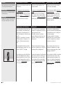
Wir garantieren eine einwand–
freie Funktion unserer Geräte,
sofern diese sachgemäß und
nach den Richtlinien unserer Betriebsanleitung angeschlossen und
bedient werden.
We warrant the perfect functioning of our products, provided
they have been installed and operated correctly according to our
operating instructions.
Nous garantissons un fonctionnement irréprochable de nos
appareils sous conditions d’une
mise en service compétente et
correspondant à nos normes et
notices d’emploi.
Sofern nachweislich Herstell- oder
Materialfehler vorliegen, werden
die fehlerhaften Teile nach unserer
Wahl kostenlos in Stand gesetzt
oder ersetzt.
If production or material faults
can be proved, the defective parts
will be repaired or replaced free of
charge at our discretion.
Si un défaut de fabrication ou de
matériau peut être prouvé, les
pièces défectueuses seront réparées ou remplacées gratuitement.
Die Rücksendung hat in der Original- oder einer gleichwertigen
Verpackung zu erfolgen.
A defective pump must be returned in the original ISMATEC®
packing or in a packet of equal
quality.
Le renvoi doit être effectué dans
l’emballage d’origine ou similaire.
Für Pumpenköpfe von anderen
Herstellern als ISMATEC SA gelten
die Garantiebestimmungen des
Herstellers.
For pump heads from manufacturers other than ISMATEC SA
the warranty terms of the specific
manufacturer are valid.
Pour les têtes de pompe d’autres
fabricants qu’ISMATEC SA, ce
sont les dispositions de garanties
du fabricant qui s’appliquent.
Durch Inanspruchnahme einer
Garantieleistung wird die Garantiezeit nicht beeinflusst.
The duration of the warranty is
not affected by making a claim
for warranty service.
La durée de la garantie n’est pas
touchée par le fait que le client
demande une prestation de garantie.
Weitergehende Forderungen sind
ausgeschlossen.
Further claims are excluded.
Toute autre prétention est exclue.
Frachtkosten gehen zu Lasten des
Kunden.
Shipping costs are charged to the
customer.
Les frais d’expédition sont facturés au client.
MCP Standard/ISMATEC SA/12.06.07/CB/GP
b
Garantie
Bei Unklarheiten wenden Sie sich
bitte an Ihre ISMATEC®-Vertretung.
b
Garantiebestimmungen
Warranty terms
Garantie
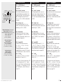
Unsere Garantie erlischt,
wenn:
Our warranty becomes invalid
in the case of:
Notre garantie perd sa validité
dans les cas suivants:
■
das Gerät unsachgemäß bedient oder zweckentfremdet
wird
■
improper operation by the user,
or if the pump is diverted from
its proper use
■
manipulation inadéquate par
l’utilisateur ou utilisation de
l’appareil à des fins auxquelles il
n’est pas destiné
■
am Gerät Eingriffe oder Veränderungen vorgenommen werden
■
unauthorized modification or
misuse by the user or by a third
party
■
modifications non autorisées ou
mauvais emploi par l’utilisateur
ou un tiers
■
ein für das Gerät unangemessener Standort gewählt wird
■
improper site preparation and
maintenance
■
préparation et entretien inadéquats de l’emplacement de
l’appareil
■
das Gerät umwelt- und elektrospezifisch unter Bedingungen
eingesetzt wird, für die es nicht
vorgesehen ist
■
operation outside of the environmental and electrical specifications for the product
■
utilisation de la pompe en dehors de l’environnement et des
spécifications électriques définies pour le produit
■
Software-, Hardware, Zubehör
oder Verbrauchsmaterial eingesetzt wird, welches nicht unseren Angaben entspricht.
■
use of third-party software,
hardware, accessories or consumables purchased by the user
and which do not comply with
our specifications.
■
utilisation de matériel, de
logiciels, d’interfaces ou de
produits de consommation tiers
achetés par l’utilisateur et qui
ne satisfont pas à nos spécifications.
Warranty
In case of any queries, please contact your ISMATEC® representative.
b
Garantie
Pour toute demande, veuillez
prendre contact avec votre représentant ISMATEC®.
MCP Standard/ISMATEC SA/12.06.07/CB/GP
7
Produkt
Product
Produit
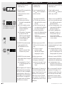
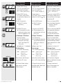
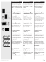
Packungsinhalt
Contents of the package
Emballage
■
■
■
8
Antrieb MCP Standard
Bestell-Nr. ISM 404
1 Netzkabel mit IEC 320- Gerätestecker (weiblich) und länderspezifischem Netzstecker
Betriebsanleitung
■
■
■
MCP Standard drive
Order No. ISM 404
1 power cord with an IEC 320
connector (female plug) and a
country specific mains plug
Operating manual
■
■
■
Moteur MCP Standard
No de commande ISM 404
1 câble réseau avec prise
IEC 320 pour appareils (femelle)
et une prise réseau spécifique
au pays de livraison.
Mode d’emploi
Sofern bestellt:
■ Pumpenkopf mit
Wechselplatte
■ weiteres Zubehör
If ordered:
■ pump head with
mounting plate
■ other accessories
Si commandés:
■ Tête de pompe avec
plaque de montage
■ Autres accessoires
Überprüfen Sie die Verpackung
und den Inhalt auf Transportschäden. Finden sich Anzeichen von
Beschädigungen, kontaktieren Sie
bitte umgehend Ihre ISMATEC®Vertretung.
Please check the package
and its contents for transport
damage. If you find any signs of
damage, please contact your local
ISMATEC® representative immediately.
Veuillez contrôler l’emballage
et son contenu et contacter immédiatement votre représentant
ISMATEC® si vous deviez constater
des dommages dus au transport.
kReklamationen können nur
innerhalb von 8 Tagen nach
Erhalt der Ware angenommen
werden.
kComplaints can only be accepted within 8 days from receipt
of the goods.
kLes réclamations éventuelles ne
seront acceptées que dans les
8 jours suivant la livraison.
MCP Standard/ISMATEC SA/12.06.07/CB/GP
1
5
2
8
7 6
3
4
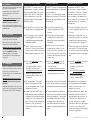
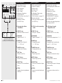
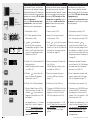
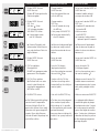
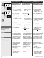
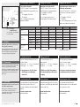
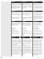
Geräterückwand
Rear panel
Tableau arrière
1 Anschluss für Fuß-Schalter bzw.
Dosierhandgriff
2 Lüfter
3 Sicherungshalter mit
Spannungswähler 115/230 V
4 Netzbuchse
5 RS232 In (Eingang, weiblich)
6 RS232 Out (Ausgang, männlich)
7 Ventilanschluss
8 Analogschnittstelle
■ Eingänge für:
- Drehzahlsteuerung
0 – 5 V oder 0 – 10 V, bzw.
0 – 20 mA oder 4 – 20 mA
- Drehrichtung
- Start/Stopp
■ Ausgänge für:
- Drehzahl 0 – 10 VDC
oder 0 – 12 kHz
1 Socket for footswitch and
hand dispenser
2 Ventilator
3 Fuse-holder with voltage
selector 115/230 V
4 Mains socket
5 RS232 In (female)
6 RS232 Out (male)
7 Valve connector
8 Analog interface
■ input for:
- speed control
0 – 5 V or 0 – 10 V, and
0 – 20 mA or 4 – 20 mA
- rotation direction
- Run/Stop
■ Output for:
- speed 0 – 10 VDC
or 0 – 12 kHz
1 Prise pour pédale de commande
et poignée dispensatrice
2 Ventilateur
3 Porte-fusibles avec sélecteur de
tension 115/230 V
4 Prise d’alimentation
5 RS232 In (entrée femelle)
6 RS232 Out (sortie mâle)
7 Raccordement de soupape
8 Interface analogique
■ Entrée:
- commande de vitesse
0 – 5 V ou 0 – 10 V, resp.
0 – 20 mA ou 4 – 20 mA
- sens de rotation
- marche/arrêt
■ Sortie:
- vitesse 0 – 10 VCC
ou 0 – 12 kHz
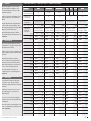
Netzspannung
Netzspannung
Vorgabe
220 – 240 VAC 230 V 50/60 Hz
110 – 120 VAC 115 V 50/60 Hz
Fenster für Spannungswahlanzeige
Window for voltage setting
Fenêtre de réglage de la tension
MCP Standard/ISMATEC SA/12.06.07/CB/GP
Mains voltage
Tension d‘alimentation
Sicherung
Mains
voltage
Voltage
setting
Fuse rating
(slow-blow)
Tension
Réglage de
d'alimentation la tension
2 x 1.25 A T
2 x 2.50 A T
220 – 240 VAC
110 – 120 VAC
230V 50/60 Hz
115V 50/60 Hz
2 x 1.25 A
2 x 2.50 A
220 – 240 VAC
110 – 120 VAC
Fusibles
de sécurité
230 V 50/60 Hz 2 x 1.25 A*
115 V 50/60 Hz 2 x 2.50 A*
*à action retard
Vor der Inbetriebnahme
Before starting-up
Avant la mise en service
Prüfen Sie, ob die Spannungswahlanzeige im Fenster des Sicherungshalters der Netzspannung
Ihres Landes entspricht.
Check if the voltage setting visible
in the window of the fuse-holder
complies with your local mains
voltage.
Wenn nötig, muss die Einstellung
geändert und die 2 Sicherungen
ausgetauscht werden.
If necessary, the voltage setting
must be changed and the 2 fuses
must be replaced.
Si nécessaire, modifiez la tension
et remplacez les deux fusibles correspondants.
Steckdose/Netzkabel
Socket/Power cord
Prise/câble d’alimentation
Verwenden Sie ausschließlich das
mitgelieferte Originalkabel. Die
Steckdose muss geerdet sein.
(Schutzleiterkontakt)
Use exclusively the original power
cord supplied with the pump. The
socket must be earthed. (protective conductor contact)
Contrôlez si la tension indiquée
dans la fenêtre du porte-fusibles
correspond à la tension de votre
réseau local.
N’utilisez que le câble
d’alimentation d’origine fourni
avec la pompe. La prise doit être
raccordée à la terre (contact conducteur de protection).
9
2
4
k
1
3
230 V: 2x1.25 A T
115 V: 2x2.50 A T
2
k
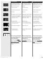
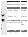
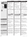
1 Sicherungshalter
Fuse-holder
Porte-fusibles
3 Position der 2 Sicherungen
Location of the 2 fuses
Position des 2 fusibles
4 Fenster im Sicherungshalter
Window in the fuse-holder
Fenêtre sur le porte-fusibles
b
Steuerprint
Control board
Panneau de commande
10
Voltage setting 115/230 V
Changing the fuses
Commutation de la tension 115/230V
Remplacement des fusibles
k Pumpe ausschalten,
Netzstecker ausziehen.
k Switch the pump off,
pull out the mains plug.
1 Sicherungsschublade mit einem
kleinen Schraubenzieher (Gr. 0)
öffnen und herausziehen.
2 Spannungswahl-Plättchen herausnehmen und mit gewünschtem Spannungswert gegen das
Fenster im Sicherungshalter
gerichtet wieder einrasten.
1 Pull out the fuse-holder by opening it with a small screw-driver
(size 0).
2 Take out the voltage selector
plate. Turn it and re-insert it
into the fuse-holder so that
the required voltage rating is
facing the window of the fuseholder.
k Eteindre la pompe. Déconnecter le câble d’alimentation
1 Extraire le porte-fusible en
ouvrant la pince supérieure et
inférieure par exemple avec un
tournevis de la taille 0.
2 Extraire la plaquette de sélection de la tension. La tourner
et la réinsérer dans le portefusibles de manière à ce que
la valeur de tension souhaitée
soit dirigée contre la fenêtre du
porte-fusibles.
3 2 neue Sicherungen einsetzen
k 230 V: 2 x 1.25 A T
k 115 V: 2 x 2.50 A T
3 Insérer deux nouveaux fusibles
3 Insert 2 new fuses
k 230 V: 2 x 1.25 A (retard)
k 230 V: 2x1.25 A (slow-blow)
k 115 V: 2 x 2.50 A (retard)
k 115 V: 2x2.50 A (slow-blow)
2 Spannungswahl-Plättchen
Voltage selector plate
Plaquette de sélection
de la tension
a
Spannungsumschaltung 115/230 V
Sicherungen wechseln
Immer 2 Sicherungen
(träge) vom selben Typ, entsprechend der ortsüblichen Netzspannung, einsetzen
Use always 2 slow-blow fuses of the same type complying
with the local mains voltage.
N’employer toujours que
deux fusibles (à action retardée)
correspondant à la tension du
circuit local.
4 Sicherungsschublade schließen.
Spannungswert ist im Fenster
sichtbar.
4 Shut the fuse-holder. The voltage rating is visible in the window.
4 Fermer le porte-fusibles. La valeur de tension est visible dans
la fenêtre.
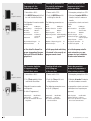
Auswechseln der Sicherungen
auf dem Steuerprint
Changing the fuses
on the control board
Remplacement des fusibles
sur le panneau de commande
Die 2 Sicherungen sind auf dem
Steuerprint wie nebenstehend
abgebildet angebracht.
The 2 fuses are fixed to the control board as illustrated opposite.
Les 2 fusibles sont fixés sur le
tableau de commande conformément à la photo ci-contre.
a 4.0 A, träge
b 1.6 A, flink
a 4.0 A, slow-blow
b 1.6 A, fast-blow
a 4.0 A, à action retardée
b 1.6 A, à action rapide
k Vergewissern Sie sich, dass die
Pumpe vom Netz getrennt ist.
Das Gerät darf nur von
einer Fachkraft geöffnet werden! Spannungsführende Teile
im Innern des Gerätes können
auch längere Zeit nach Ziehen des
Netzsteckers noch unter Spannung stehen.
k Make sure that the pump is
disconnected from the mains
supply.
The instrument should
only be opened by a qualified
technician! Capacitors inside the
pump may still be charged even
though the mains plug has been
disconnected some time ago.
k Assurez-vous que la pompe
soit déconnectée du réseau.
Cet appareil doit être
ouvert par un spécialiste uniquement!
Des pièces conductrices peuvent
encore être sous tension très
longtemps après que le câble ait
été débranché de la prise.
MCP Standard/ISMATEC SA/12.06.07/CB/GP
Inbetriebnahme
MCP Standard/ISMATEC SA/12.06.07/CB/GP
Starting the pump
Mise en route
■
Pumpenkopf gemäß separater
Montageanleitung für Pumpenköpfe montieren
■
Mount the pump head according to the mounting instruction manual supplied with the
pump head
■
Installer la tête de pompe selon
le manuel d’utilisation fourni
avec la tête de pompe.
■
ID-Codes der verwendeten
Pumpenköpfe in die entsprechend benutzten Programmspeicher eingeben
(siehe Seite 16 und 50).
■
Enter the ID Codes of the
mounted pump heads in the
program memory currently used
(see pages 16 and 50).
■
Saisir les numéros d’identification des têtes de pompes employées dans la mémoire du programme (voir page 16 et 50).
■
Schlauch-iØ in jedem benutzten Programm eingeben
(siehe Seite 17).
■
Enter the tubing i.d. in each
program used
(see page 17).
■
Saisir le diamètre du tube dans
chaque programme utilisé (voir
page 17).
■
Bei FMI-Pumpenköpfen den
Winkel für das Kolbenhubvolumen einstellen
(siehe Seite 17).
■
If using an FMI piston pump
head, adjust the angle for the
piston stroke volume
(see page 17).
■
Pour les têtes de pompe FMI,
régler l’angle du volume du
mouvement depiston
(voir page 17).
■
Bei Schlauch-Pumpenköpfen
Pumpenschlauch einsetzen.
■
Insert the tubing into the peristaltic pump head.
■
Pour les pompes péristaltiques,
introduire le tube de pompe.
■
Pumpenschlauch am System
anschließen.
■
Connect the pump tubing to
the system.
■
Connecter le tube de la pompe
au système.
■
Pumpe am Netz anschließen
und mit dem Netzschalter einschalten.
■
Connect the pump to the mains
and switch it on with the power
supply switch.
■
Raccorder la pompe au réseau et mettre en route avec
l’interrupteur de réseau.
11
1
2
3 4
10
TUBE I.D.
PUMP
DISP
PAUSE
9
mm
rpm
Time
Time
8
5 6
7
PROGRAM
Flow rate
Volume
TOTAL
Anzeige der Betriebsart
LEDs for operating modes
Affichage du mode d‘exploitation
12
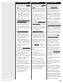
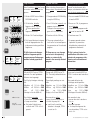
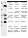
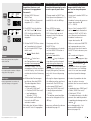
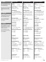
Bedienungspanel
Operating panel
Tableau de commande
1
2
3
4
5
6
7
Netzschalter (ein/aus)
Digitale LED-Anzeige
Wert reduzieren
Wert erhöhen
Start / Stopp
Kalibrieren / Speichern
MAX/MIN/RESET
(Multifunktion, siehe Seite 15)
8 Drehrichtung
9 Betriebsart wählen
k MODE-Taste
1
2
3
4
5
6
7
Mains switch (on/off)
Digital LED display
Reduce value
Increase value
Run / Stop
Calibration / Data saving
MAX/MIN/RESET
(Multi-function, see page 15)
8 Rotation direction
9 Selecting the operating mode
k MODE key
1 Commutateur principal
2 Affichage digital à diodes lumineuses
3 Réduire la valeur
4 Augmenter la valeur
5 Marche/Arrêt
6 Calibration/mémorisation
7 MAX/MIN/RESET (fonctions
multiples, voir page 15)
8 Sens de rotation
9 Sélection du mode d’opération
k touche MODE
10 Anzeige der aktiven
Betriebsart
10 LEDs for active operating
mode
10 Affichage du mode
d’opération actif
■
TUBE I.D. mm
Wahl des Schlauch-Innen-Ø
■
TUBE I.D. mm
Tubing i.d. selection
■
TUBE I.D. mm
Sélection du Ø int. des tubes
■
PROGRAM
Programmwahl 1 – 4
■
PROGRAM
Program selection 1 – 4
■
PROGRAM
Sélection des programmes 1 – 4
■
PUMP rpm
Pumpen nach Drehzahl
1.0 – 240.0 min–1
■
PUMP rpm
Pumping by speed
1.0 – 240.0 rpm
■
PUMP rpm
Pompage selon le nombre de
tours 1.0 – 240.0 t/min
■
PUMP Flow rate
Pumpen nach Fließrate
■
PUMP Flow rate
Pumping by flow rate
■
PUMP Flow rate
Pompage selon le débit
■
DISP Time
Dosieren nach Zeit
■
DISP Time
Dispensing by time
■
DISP Time
Dosage en fonction du temps
■
DISP Volume
Dosieren nach Volumen
■
DISP Volume
Dispensing by volume
■
DISP Volume
Dosage selon le volume
■
PAUSE Time
Pausenzeit für Intervalldosierung
■
PAUSE Time
Pause for intermittent dispensing
■
PAUSE Time
Temps de pause pour le dosage
par intervalles
■
TOTAL
Angabe des total geförderten
Volumens
■
TOTAL
Read-out of totally delivered
volume
■
TOTAL
Indication du volume total refoulé
MCP Standard/ISMATEC SA/12.06.07/CB/GP
1
2
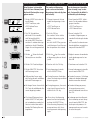
Start-Information
Start-up information
Informations de mise en route
Die folgenden Einstellungen
leuchten nach dem Einschalten
des Netzschalters kurz auf:
After switching on the power
supply, the following values are
displayed:
Les réglages suivants s’illuminent
brièvement après la mise en route
de l’interrupteur de réseau:
1 LED-Test »8.8.8.8.«
1 LED test »8.8.8.8.«
1 Test LED »8.8.8.8.«
2 Version der Systemsoftware
2 Firmware version
2 Version du logiciel système
3 Baudrate
3 Baud rate
3 Nombre de bauds
4 Identifikations-Code (ID-Code) des 4 Identification Code (ID-Code) of 4 Code d’identification (code ID)
im zuletzt benutzten Programm
de la dernière tête de pompe
the pump head entered in the
gespeicherten Pumpenkopfes (z.B.
mémorisée dans le dernier proprogram last used (e.g. pump
Kopf 380AD = 380A)
gramme employé (par exemple
head 380AD = 380A)
tête 380AD = 380A)
3
4
5 Rollenrückschritte
k Leuchten nur auf, wenn mehr
als 0 eingegeben wurde
5 Roller back-steps
k are only displayed if at least
1 or more back-steps are entered
5 Pas arrière des galets
k Ne s’illuminent que si un
nombre supérieur à 0 a été saisi
5
6 Zuletzt benutztes Programm
6 Program last used
6 Dernier programme d‘opération
utilisé
6
7 Anzeige der zuletzt
benutzten Betriebsart
7 Displays the operating mode
last used
7 L‘affichage s‘arrête sur le dernier
mode d'opération utilisé
Before starting the pump
Avant de mettre la pompe
7
TUBE I.D.
PUMP
DISP
PAUSE
mm
rpm
Time
Time
PROGRAM
Flow rate
Volume
TOTAL
MCP Standard/ISMATEC SA/12.06.07/CB/GP
Vor der ersten Inbetriebnahme oder nach Montage eines
neuen Pumpenkopfes
muss der ID-Code in jedem mit
diesem Pumpenkopf zu verwendenden Programm separat eingegeben werden (siehe Seite 16
und 50).
the first time or after mounting
a new pump head,
the ID-Code must be entered
in each program used with this
pump head (see page 16 and 50).
en marche pour la première fois
ou après l’installation d’une
nouvelle tête de pompe,
saisir le code ID dans chaque programme employé avec cette tête
de pompe (voir page 16 et 50).
13
aus
off
couper le contact
1
2
MODE
ein
on
mettre
le contact
Die Parameter des aktuellen
Programms auf ihre
Default-Werte setzen.
Resetting the parameters of
the currently used program
to the default values.
Remise des paramètres du
programme actuel à leurs
valeurs par défaut.
1 Netzschalter »AUS«
1 Power switch »OFF«
1 Interrupteur principal sur »OFF«
2 Die MODE-Taste gedrückt halten und Antrieb einschalten
2 Push the MODE key whilst
switching the drive on
Die folgenden Parameter werden
zurückgesetzt:
The following parameters are
reset:
2 Maintenir la touche MODE enfoncée et mettre le moteur en
marche.
Les paramètres suivants sont remis
à zéro:
Modus:
Drehrichtung:
Drehzahl:
Dosierzeit:
Dosiervolumen:
Mode:
Rotation direction:
Speed:
Dispensing time:
Dispensing volume:
Pausenzeit:
PUMP rpm
Uhrzeigersinn
100 min–1
4.5 Sek.
Volumen je
nach Kopf
2.0 Sek.
Dosierwiederholungen:
Rollenrückschritte:
1
2
14
aus
off
couper le contact
ein
on
mettre
le contact
12
0
Pause time:
PUMP rpm
clockwise
100 rpm
4.5 sec.
volume depending
on pump head
2.0 sec.
Number of dispensing cycles:
Roller back-steps:
12
0
Mode:
Sens de rotation:
PUMP rpm
des aiguilles
d’une montre
Nbre de tours:
100 t/min
Durée de dosage: 4.5 sec.
Volume de dosage: volume selon
a tête de pompe
Temps de pause:
2.0 sec.
Dosages par intervalles:
12
Pas arrière des galets:
0
k Der aktuell in diesem Programm eingegebene Pumpenkopf und Schlauch-iØ bleiben
gespeichert.
k Both pump head and tubing
i.d. entered in the currently set
program remain stored.
k La tête de pompe actuellement mémorisée sur ce programme ainsi que le diamètre
du tube restent mémorisés.
Die Parameter sämtlicher
4 Programme auf ihre
Default-Werte setzen.
Resetting default values
of all 4 programs
at the same time
Remise des paramètres
de tous les 4 programmes à
à leurs valeurs par défaut.
1 Netzschalter »AUS«
1 Power switch »OFF«
1 Interrupteur principal sur »OFF«
2 Die 6Taste gedrückt halten
und Antrieb einschalten
2 Push the 6 key whilst switching the drive on.
2 Maintenir la touche 6enfoncée
et mettre le moteur en marche
Folgende Parameter werden
zurückgesetzt
(in allen 4 Programmen):
The following parameters are reset (in all 4 programs):
Les paramètres suivants sont remis
à zéro (dans tous les quatre programmes):
Pumpenkopf:
Modell MS-3
Schlauch-iØ:
0.13 mm
k sowie alle Parameter wie oben
aufgeführt
Pump head:
Model MS-3
Tubing i.d.:
0.13 mm
k as well as all parameters
mentioned above
Tête de pompe:
modèle MS-3
Diamètre du tube: 0.13 mm
k et tous les paramètres correspondent à ceux susmentionnés
MCP Standard/ISMATEC SA/12.06.07/CB/GP
a
b
MODE
TUBE I.D.
PUMP
DISP
PAUSE
mm
rpm
Time
Time
c
d
CAL
e
f
MCP Standard/ISMATEC SA/12.06.07/CB/GP
PROGRAM
Flow rate
Volume
TOTAL
Steuertasten
Control keys
Touches de commande
a RUN/STOP
Pumpe starten bzw. stoppen
a RUN/STOP
Starts and stops the pump
b MODE
Wechselt zwischen den
Betriebsarten (siehe Seite 12)
b MODE
Changes between operating
modes (see page 12)
c Drehrichtung
Wechselt die Drehrichtung.
■ Diese Funktion ist beim
Membran-Pumpenkopf
blockiert.
■ Bei jedem Drehrichtungswechsel wird TOTAL auf
»0« gesetzt.
■ Funktioniert nur in den
Betriebsarten:
- PUMP rpm
k Minus-Zeichen
= Gegenuhrzeigersinn
- PUMP Flow rate
d CAL
Speichertaste für Werteingabe
c Rotation direction
Changes the rotation direction.
■ This function is blocked
when using the diaphragm
pump head
■ Each time the rotation
direction is changed,
TOTAL is reset to »0«.
■ Functions only in the
operating modes:
- PUMP rpm
k minus sign
= reverse direction
- PUMP Flow rate
d CAL
Key for saving a set value
e MAX/MIN/RESET
Multifunktionstaste für:
k max. Drehzahl
(bei laufender Pumpe)
k min. Drehzahl
(bei ruhender Pumpe)
dreht langsam, z.B. für
Pumpenkopf-Montage
k Reset-Taste setzt Kalibrierung auf Standardwerte
(Default), Seite 14
k Reset-Taste für kumuliertes
Volumen im Modus TOTAL
e MAX/MIN/RESET
Multifunction key for:
k max. speed
(when pump is running)
k min. speed
(when pump is idle)
turns slowly, e.g. for
mounting a pump head
k Reset button resets the
calibration to the standard
values (default), page 14
k Reset button for
accumulated volume in
Mode TOTAL
f Werteingabe
5 = höhere Werte
6 = kleinere Werte
Bei längerem Drücken der
5oder 6Tasten wechselt die
Display-Anzeige in den Schnelllauf-Modus.
f Increment/Decrement keys
5 = increase value
6 = decrease value
Maintaining pressure on
5or 6key changes display
read-out into fast mode.
a RUN/STOP
Mettre en route ou arrêter la
pompe
b MODE
Passage d'un mode d'opération à un autre (voir page 12)
c Sens de rotation
Change le sens de rotation.
■ Cette fonction est bloquée
sur la tête de pompe à
diaphragme.
■ A chaque changement du
sens de rotation, TOTAL est
remis sur »0«.
■ Ne fonctionne qu’avec les
modes de fonctionnement:
- PUMP rpm
k Signe moins
= sens contraire aux aiguilles
d’une montre
- PUMP Flow rate
d CAL
Touche 'Entrée' pour entrée de
valeurs
e MAX/MIN/RESET
Touche multifonctions pour
k nombre de tours maximal
(lorsque la pompe fonctionne)
k nombre de tours minimal
(lorsque la pompe ne fonctionne pas) tourne lentement, par
exemple pour l’installation de
la tête de pompe
k Bouton de remise à zéro:
remet le calibration aux valeurs
standard (par défaut), pages 14
k Bouton de remise à zéro du
volume cumulé en mode
TOTAL
f Touche pour la définition
des valeurs
5 = accroître la valeur
6 = réduire la valeur
En maintenant les touches
5ou 6 pressées, l‘affichage
commute en mode rapide.
15
aus
off
couper le contact
1
2
ein
on
mettre
le contact
CAL
3
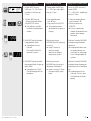
Pumpenkopf-Identifikation
Pump head identification
L‘identification de la tête de pompe
Für korrekte Pump- und DosierWerte muss die richtige Pumpenkopf-Identifikation (ID-Code) des
jeweils montierten Pumpenkopfes
gespeichert werden ( für jedes
der 4 Programme).
Vor allem bei der ersten Inbetriebnahme und nach jedem
Wechsel eines Pumpenkopfes.
In order to obtain correct pumping
and dispensing values the individual identification code (ID-Code)
of the mounted pump head must
be entered ( for each of the
4 programs), especially when a
new pump is used for the first
time and each time the pump
head is changed.
Pour obtenir des valeurs correctes, il faut introduire le code
d‘identification de la tête de pompe installée ( dans chacun des
4 programmes),
surtout avant la première mise
en route ou après avoir changé la
tête de pompe.
1 Netzschalter »AUS«
1 Power switch »OFF«
1 Interrupteur principal 'OFF'
2 CAL-Taste gedrückt halten
Netzschalter »EIN«
2 Keep CAL-key pressed and
switch power »ON«
2 Maintenir la touche CAL enfoncée. Interrupteur principal 'ON'
3 Press 5or 6 key till the correct
ID-Code of the mounted pump
head is set. For the ID-Code see
the back of the pump head or
the table on page 50
3 Presser la touche 5ou 6
jusqu’à ce que le code ID correct de la tête de pompe installée clignote. Le code ID est indiqué sur la face arrière de la tête
de pompe ou dans le tableau à
la page 50
4 Mit der CAL-Taste korrekten IDCode speichern
(Mode-Anzeige schaltet autom.
auf TUBE I.D.)
4 Enter the correct ID-Code with
the CAL-key
(MODE display switches automatically to TUBE I.D.)
4 Mémoriser le code ID correct
avec la touche CAL (l’affichage
du mode commute automatiquement sur TUBE I.D.)
5 Mit den 56 Tasten den richtigen Schlauch-iØ eingeben
(siehe auch Seite 17)
5 Enter the correct tubing i.d.
with the 56 keys (see also
page 17)
5 Saisir le diamètre du tube adéquat au moyen de les touches
56 (cf. également page 17)
6 Mit der CAL-Taste bestätigen
6 Confirm with the CAL-key
6 Confirmer avec la touche CAL
7 Mit der Mode-Taste auf PROGRAM wechseln, mit der CAL
und den 56 Tasten nächstes
Programm anwählen (mit CAL
bestätigen).
7 Change to PROGRAM with the
MODE key and select the next
program with the CAL and
56 keys (confirm with CAL).
7 Commuter sur PROGRAM avec
la touche MODE, sélectionner
le programme suivant avec la
touche CAL et les touches 56
(confirmer avec CAL)
k Repeat procedure 1 – 6 till
the ID-Code(s) of the mounted
pump head(s) and the tubing
i.d. are entered in all 4 programs.
k Répéter la procédure de 1 à 6
jusqu’à ce que le code ID de la
tête de pompe et le diamètre
int. du tube employés soient
mémorisés dans chacun des
4 programmes.
3
4 CAL
TUBE I.D.
PUMP
DISP
PAUSE
5
6 CAL
7
MODE
CAL
CAL
mm
rpm
Time
Time
PROGRAM
Flow rate
Volume
TOTAL
5 oder 6Taste drücken,
bis der für den montierten
Pumpenkopf richtige ID-Code
blinkt. Für ID-Code siehe Rückseite des Pumpenkopfes bzw.
Tabelle auf Seite 50
k Vorgehen von 1 – 6 wiederholen, bis in allen 4 Programmen der ID-Code des jeweils
verwendeten Pumpenkopfes
und der Schlauch-iØ gespeichert sind.
16
MCP Standard/ISMATEC SA/12.06.07/CB/GP
Schlauch-Innendurchmesser
oder Hubwinkel eingeben
Entering the tubing i.d.
or stroke angle
Saisie du diamètre de tube
ou de l'angle de course
Für korrekte Fließraten und
Before starting to pump it is
Avant de mettre la pompe en
NUR für
Peristaltik-Pumpenköpfe
ONLY for
Peristaltic pump heads
SEULEMENT pour
Têtes de pompe péristaltique
1 Mit der MODE-Taste auf
TUBE I.D. mm (für die Eingabe
des Schlauch-Innen-Ø)
2 CAL-Taste drücken
(Anzeige blinkt)
3aBlinkende Zahl mit gewünschtem Schlauch-iØ vergleichen
4
Tasten drücken bis richtiger
iØ angezeigt wird
5 Mit der CAL-Taste speichern
k Mit MODE gewünschte Betriebsart wählen.
1 Change mode to
TUBE I.D. mm (for setting the
tubing inner diameter)
2 Press CAL-key
(display blinks)
3aCompare blinking figure with
required tube i.d.
4 Press
keys until correct i.d. is
displayed
5 Confirm entered value with
CAL-key
k Select required operation
mode with MODE-key
1 Passer en mode TUBE I.D. mm
avec la touche MODE (pour introduire le Ø int. des tubes)
2 Presser la touche CAL
(l’affichage clignote)
3a Comparer le nombre qui
clignote avec le Ø int. du tube
souhaité
4 Presser les touches
jusqu’à
ce que le bon Ø int. soit affiché
5 Mémoriser avec la touche CAL
k Sélectionner le mode d’exploitation souhaité avec MODE
NUR für
FMI-Kolben-Pumpenköpfe
ONLY for
FMI piston pump heads
SEULEMENT pour
têtes de pompe à piston FMI
Hubeinstellung
Unter TUBE I.D. mm kann der
Winkel wie unter Pos. 1 – 5 beschrieben eingestellt werden:
Setting the stroke volume
In mode TUBE I.D. mm the piston
angle can be entered as stated
above from position 1 to 5:
Réglage du déplacement du
piston
L’angle du piston peut être réglé
dans le mode TUBE I.D. mm comme décrit en pos. 1 – 5:
3b Kolbenwinkel (von 1 – 10)
eingeben
k Gleicher Winkel muss auch
am Pumpenkopf eingestellt
sein.
3b set piston angle (between
1 and 10)
k The same angle must also
be manually set on the
pump head.
NUR für
Membranpumpenköpfe
ONLY for
Diaphragm pump heads
SEULEMENT pour
têtes de pompe à diaphragme
Schlauch-Ø ist irrelevant. In der
Betriebsart TUBE I.D. mm erscheint die Anzeige »0.0«.
Tube i.d. is not relevant.
In mode TUBE I.D. mm the display
shows »0.0«.
Le Ø du tube n’a aucune importance. L’affichage »0.0« apparaît
en mode TUBE I.D. mm.
Dosiervolumen sind vor Beginn
der Arbeit die nachstehenden Eingaben wichtig:
1
2
MODE
TUBE I.D.
PUMP
DISP
PAUSE
mm
rpm
Time
Time
PROGRAM
Flow rate
Volume
TOTAL
CAL
iØ
i.d.
Ø int.
3a
Peristaltik-Pumpenkopf
Peristaltic pump head
Tête péristaltique
Winkel
Angle
3b
Kolben-Pumpenkopf
Piston pump head
Tête piston
4
5 CAL
MCP Standard/ISMATEC SA/12.06.07/CB/GP
56
essential to enter the following
settings in order to obtain correct
flow rates and dispensing volumes.
56
marche, il est indispensable de
saisir les réglages suivants si l’on
désire obtenir des débits et des
volumes de dosage corrects.
56
3b Introduire l’angle du piston
(de 1 à 10)
k Le même angle doit être réglé manuellement sur la tête de
pompe
17
Programmwahl
1 MODE
TUBE I.D.
PUMP
DISP
PAUSE
mm
rpm
Time
Time
PROGRAM
Flow rate
Volume
TOTAL
2 CAL
3 CAL
4
TUBE I.D.
PUMP
DISP
PAUSE
mm
rpm
Time
Time
PROGRAM
Flow rate
Volume
TOTAL
Program selection
Sélection du programme
Beim Einschalten wählt die Pumpe When switching the pump on, it
immer das zuletzt benutzte Proalways selects the previously used
gramm.
program.
Lors de l’enclenchement de la
pompe, cette dernière choisit toujours le dernier programme utilisé.
1 Mit der MODE-Taste in Modus
PROGRAM wechseln.
1 Change mode to PROGRAM by
using the MODE-key.
1 Passer en mode PROGRAM avec
la touche MODE
2 CAL drücken, aktuelles
Programm blinkt. Mit den
56Tasten gewünschtes
Programm anwählen
2 Press CAL button, currently set
program starts to blink
Change to the required program with the 5
6buttons
2 Pressez sur CAL, le programme
actuel clignote
Sélectionnez le programme désiré avec les touches 5
6
3 Mit der CAL-Taste bestätigen
3 Confirm with the CAL-key
3 Confirmez avec CAL
4 Die Pumpe übernimmt automatisch die abgespeicherten Betriebsparameter des gewählten
Programms.
4 The pump automatically returns to the last entered operating parameters of the selected
program.
4 La pompe reprend automatiquement les paramètres
d’exploitation mémorisés du
programme sélectionné.
Alle fortan unter dem ge-
From now on, any changes
Dès à présent, toutes les
Total-Volumen
TOTAL Volume
Volume total
Mit der MODE-Taste auf TOTAL
wechseln. Das total geförderte
Volumen wird angezeigt.
Change with MODE key to TOTAL. The totally delivered volume
is displayed.
Passer avec la touche MODE sur
TOTAL. Le volume total refoulé est
affiché.
Drei Display-Anzeigen sind möglich:
Mikroliter: z.B. 12.0 µl = 12.0µ
Milliliter: z.B. 1200 ml = 1200
Liter:
z.B.
12.0 l = 12.0L
(Anzeige in Liter ab 9999 ml)
Three display readings are available:
Microlitre: e.g. 12.0 µl = 12.0µ
Millilitre:
e.g. 1200 ml = 1200
Litre:
e.g. 12.0 l = 12.0L
(Display in litres from 9999 ml)
Trois mode de lecture de
l'affichage sont disponibles:
Microlitres: p.e. 12.0 µl = 12.0µ
Millilitres: p.e. 1200 ml = 1200
Litres:
p.e. 12.0 l = 12.0L
(Affichage en litres dès 9999 ml)
Zum Löschen entweder
• Reset-Taste 2 x drücken oder
• Pumpe ausschalten.
k Bei jedem Drehrichtungswechsel wird TOTAL auf »0«
gesetzt.
For zero-setting, either
• press the reset key twice, or
• switch the pump off.
k each time the rotation
direction is changed, TOTAL
is reset to »0«.
Pour remettre à zéro:
• presser deux fois la touche reset, ou
• éteindre la pompe.
k A chaque changement du
sens de rotation, TOTAL est remis à »0«.
wählten Programmspeicher
vorgenommenen Änderungen
werden laufend gespeichert.
carried out in the operating
modes are automatically
stored in the currently selected
program.
modifications effectuées sur la
mémoire de programme sélectionnée sont continuellement
mémorisées.
z.B. / e.g. / p.e. PUMP rpm
MODE
TUBE I.D.
PUMP
DISP
PAUSE
mm
rpm
Time
Time
PROGRAM
Flow rate
Volume
TOTAL
2x
oder / or / ou
aus / off
couper le contact
18
MCP Standard/ISMATEC SA/12.06.07/CB/GP
1
MODE
TUBE I.D.
PUMP
DISP
PAUSE
mm
rpm
Time
Time
2
3
PROGRAM
Flow rate
Volume
TOTAL
Pumpen nach Drehzahl
Pumping by drive speed
Pompage selon le nombre de tours
1 Mit der MODE-Taste auf
PUMP rpm, 1.0 – 240.0 min–1,
einstellbar in Schritten von
0.1 min–1
1 Change mode to PUMP rpm,
1.0 – 240.0 rpm, adjustable in
steps of 0.1 rpm
1 Passer sur PUMP rpm avec la
touche MODE,
1.0 – 240.0 t/min., réglable par
pas de 0.1 t/min.
2 • Mit den 5
6 Tasten gewünschte Drehzahl wählen
• Mit RUN/STOP starten
k Drehzahl kann auch bei
laufender Pumpe geändert
werden
2 • Enter required speed
with 5
6 keys
• Start pump with RUN/STOP
k The speed can also be
adjusted while the pump is
running.
2 • Choisir le nombre de tours
avec les touches 5
6
• Mettre en route avec
RUN/STOP
k Il est aussi possible de
modifier le nombre de tours
pendant que la pompe
fonctionne
3 MAX/MIN-Taste bei laufender
Pumpe gedrückt halten
k Pumpe dreht mit max.
Drehzahl
(Für schnelles Füllen/Entleeren des Systems)
3 Maintain pressure on
MAX/MIN-key while the pump
is running
k Pump is running at
maximum speed
(ideal for fast filling or
emptying the system)
3 Maintenir la touche MAX/MIN
enfoncée lorsque la pompe
fonctionne
k La pompe fonctionne avec
un nombre de tours maximal (pour un remplissage
et une vidange rapides du
système)
4 MAX/MIN-Taste bei ruhender,
aber eingeschalteter Pumpe gedrückt halten
k Pumpe dreht mit 10 min–1
(Für die Montage des Pumpenkopfes)
4 Maintain pressure on
MAX/MIN-key when pump is
idle (power switched on!)
k pump is turning at 10 rpm
(for mounting the pumphead)
4 Maintenir la touche MAX/MIN
enfoncée lorsque la pompe est
enclenchée mais ne fonctionne
pas.
k La pompe tourne à une
vitesse de 10 t/min. (pour
l’installation de la tête de
pompe)
4
.
MCP Standard/ISMATEC SA/12.06.07/CB/GP
19
1 MODE
TUBE I.D.
PUMP
DISP
PAUSE
mm
rpm
Time
Time
PROGRAM
Flow rate
Volume
TOTAL
2
z.B.12.5µl/min (siehe auch S. 21)
e.g.12.5µl/min (see also page 21)
p.e.12.5µl/min (voir page 21)
3
4
Pumpen nach Fließrate
Pumping by flow rate
Pompage selon le débit
1 Mit der MODE-Taste auf
PUMP Flow rate
1 Change mode to
PUMP Flow rate
1 Passer avec la touche MODE sur
PUMP Flow rate
2 Mit den 5
6Tasten gewünschte
Fließrate wählen
(wird in µl/min bzw. ml/min
angegeben)
2 Enter the required flow rate
with 5
6 keys (is displayed in
µl/min or ml/min)
2 Choisir le débit souhaité
avec les touches 5
6 (affiche en
µl/min, resp. ml/min)
Mit RUN/STOP starten
k Fließrate kann auch bei
laufender Pumpe geändert
werden.
k Für eine möglichst präzise
Fließrate empfehlen wir, die
Pumpe zu kalibrieren.
(siehe Seite 21)
k Während des Pumpvorganges können über die
MODE-Taste die folgenden
Werte abgelesen werden:
• Drehzahl (PUMP rpm)
• Volumen (TOTAL)
• Rotation speed (PUMP rpm)
• Volume (TOTAL)
Mettre en route avec RUN/STOP
k Il est aussi possible de modifier le débit pendant que la
pompe fonctionne
k Pour un dosage précis, il est
recommandé de calibrer la
pompe (voir page 21).
k Pendant la procédure de
pompage, les valeurs suivantes peuvent être lues
avec la touche MODE.
• Nombre de tours (PUMP rpm)
• Volume (TOTAL)
3 MAX/MIN-Taste bei laufender
Pumpe gedrückt halten
k Pumpe dreht mit max.
Drehzahl
(Ideal für schnelles Füllen/
Entleeren des Systems)
3 Maintain pressure on MAX/
MIN-key while the pump is running
k Pump is running at
maximum speed
(ideal for fast filling or
emptying the system)
3 Maintenez la touche MAX/MIN
enfoncée (pendant que la pompe fonctionne)
k La pompe fonctionne avec
un nombre de tours maximal
(pour un remplissage et une
vidange rapides du système)
4 MAX/MIN-Taste bei ruhender,
aber eingeschalteter Pumpe gedrückt halten
k Pumpe dreht mit 10 min–1
(Für die Montage des Pumpenkopfes)
4 Maintain pressure on
MAX/MIN-key when pump is
idle (power switched on!)
k pump is turning at 10 rpm
(for mounting the pumphead)
4 Maintenir la touche MAX/MIN
enfoncée lorsque la pompe est
enclenchée mais ne fonctionne pas.
k La pompe tourne à une
vitesse de 10 t/min. (pour l’installation de la tête de pompe)
Die Eingabe des ID-Codes des
Entering the ID-Code of the
La saisie du code ID de la tête
jeweilig benutzten Pumpenkopfes (Seite 16 und 50) ermöglicht
in der Betriebsart »Flow rate« in
Abhängigkeit des Schlauchdurchmessers bereits mit angenäherten, jedoch noch nicht kalibrierten Fließraten zu arbeiten.
20
Start pump with RUN/STOP
k The flow rate can also be
adjusted while the pump is
running.
k For an accurate flow rate
we recommend to calibrate
the pump (see page 21).
k During the pumping
process the following values
can be retrieved with the
MODE-key:
currently mounted pump head
(pages 16 and 50) and the inner
diameter of the tubing used
allows the user to set the flow
rate in ml/min. This, however, is
an approximate value as not yet
calibrated.
de pompe utilisée (pages 16 et
50) permet en mode »Flow rate«
de travailler déjà avec des débits
approximatifs mais pas encore
calibrés, en fonction du diamètre
du tube.
MCP Standard/ISMATEC SA/12.06.07/CB/GP
1
2
3
4
5
MODE
MODE
MODE
TUBE I.D.
PUMP
DISP
PAUSE
TUBE I.D.
PUMP
DISP
PAUSE
TUBE I.D.
PUMP
DISP
PAUSE
mm
rpm
Time
Time
mm
rpm
Time
Time
mm
rpm
Time
Time
CAL
CAL
6
MCP Standard/ISMATEC SA/12.06.07/CB/GP
PROGRAM
Flow rate
Volume
TOTAL
PROGRAM
Flow rate
Volume
TOTAL
PROGRAM
Flow rate
Volume
TOTAL
Fließrate kalibrieren
Calibrating the flow rate
Calibration du débit
1 Mit der MODE-Taste auf
PUMP Flow rate
Mit den 5
6Tasten gewünschte
Fließrate eingeben
1 Change mode to
PUMP Flow rate
Enter the required flow rate
with the 5
6 keys
1 Passer avec la touche MODE sur
PUMP Flow rate
Introduire le débit souhaité
au moyen des touches 5
6
2 Mit der MODE-Taste auf
DISP Time
• Mit den 5
6Tasten
60 Sekunden eingeben
• Mit RUN/STOP starten
k Pumpe stoppt autom.
nach 60 Sekunden
2 Change mode to
DISP Time
• Enter 60 seconds by using
the 5
6 keys
• Start pump with RUN/STOP
k Pump stops automatically
after 60 seconds
2 Passer avec la touche MODE sur
DISP Time
• Introduire 60 secondes avec
les touches 5
6
• Mettre en route
avec RUN/STOP
k La pompe s’arrête automatiquement après 60 secondes
k Dosierte Flüssigkeit nach
Volumen oder Gewicht bestimmen und erhaltenen Wert wie
folgt kalibrieren:
k Measure the dispensed liquid
by volume or weight and calibrate the ascertained value as
follows:
k Déterminer le liquide dosé
selon le volume ou le poids et
calibrer la valeur ainsi obtenue
comme suit:
3 Mit der MODE-Taste auf
PUMP Flow rate
3 Return to mode
PUMP Flow rate
3 Passer avec la touche MODE sur
PUMP Flow rate.
4 CAL-Taste drücken
(Anzeige blinkt)
Mit 5
6Taste gewogenen oder
gemessenen Wert eingeben.
4 Press the CAL-button
(displayed value blinks)
Enter the weighed or measured
value with the5
6keys
4 Presser la touche CAL
(l’affichage clignote)
Saisir la valeur pesée ou mesurée avec les touches 5
6
5 Mit CAL-Taste speichern
(die Fließrate kehrt nun automatisch in den Bereich des
ursprünglich vorgegebenen
Soll-Wertes zurück)
5 Confirm with the CAL-key
(the flow rate setting returns
automatically to the initially entered set point)
5 Mémoriser avec la touche CAL
(le débit retourne maintenant
automatiquement dans la zone
de la valeur préréglée initialement)
6 Mit RUN/STOP starten
6 Start with the RUN/STOP-key
6 Mettre en route avec RUN/STOP
k Die Fließrateneinstellung hängt
von der Anzahl Pumpenrollen
und vom Schlauch-iØ ab. Der
gewünschte Sollwert kann möglicherweise nicht genau eingestellt
werden. Wenn nötig kleineren
Schlauch-iØ oder Pumpenkopf mit
mehr Rollen wählen.
k The flow rate setting depends
on the number of pump rollers
and the tubing i.d. It is possible
that the required set point cannot
be entered accurately.
If necessary choose a tubing with
a smaller i.d. or a pump head with
more rollers.
k Le réglage du débit dépend
du nombre de galets de pompe
et du diamètre du tube. Il se peut
que la valeur prescrite souhaitée
ne puisse être réglée de manière
exacte. Si nécessaire, sélectionner
un diamètre de tube plus petit ou
une tête de pompe comportant
davantage de galets.
21
1
MODE
TUBE I.D.
PUMP
DISP
PAUSE
mm
rpm
Time
Time
PROGRAM
Flow rate
Volume
TOTAL
2
Dosieren nach Zeit
Dispensing by time
Dosage selon le temps
Die Dosierzeit kann von 0.1 s –
999 h eingegeben werden.
The dispensing time can be entered from 0.1 s to 999 h.
La durée de dosage peut être
définie entre 0.1 s – 999 h
1 Mit der MODE-Taste auf
DISP Time
2 Mit den 5
6Tasten
gewünschte Zeit eingeben
k Suchlauf beschleunigt sich,
wenn 5 oder 6Taste
gedrückt bleibt.
1 Change mode to
DISP Time
2 Enter the required dispensing
time with the 5
6 keys
k The display accelerates
when pressure on the
5 or 6key is maintained.
1 Passer avec la touche MODE sur
DISP Time
2 Introduire la durée désirée au
moyen des touches 5
6
k La procédure de recherche
s’accélère lorsque l’on maintient
les touches 5 ou 6enfoncées.
3 Mit RUN/STOP starten
3 Start pump with RUN/STOP
3 Mettre en route avec RUN/STOP
k Mit den 5
6Tasten kann die
Dosierzeit auch während des
Dosiervorganges verändert
werden. Der neu eingegebene Sollwert wirkt sich erst bei
der nächsten Dosierung aus.
k With the 5
6keys the dispensing time can be changed even
during the dispensing process.
The newly entered set point
only takes effect from the subsequent dispensing cycle.
k Le temps de dosage peut être
modifié avec les touches 5
6
également pendant le dosage.
La nouvelle valeur saisie ne sera
prise en compte que lors du
prochain dosage.
k Während des Dosiervorganges
können mit der MODE-Taste
die folgenden Werte abgelesen
werden:
• Drehzahl (PUMP rpm)
• Fließrate (PUMP Flow rate)
• total gefördertes
Volumen (TOTAL)
k Pendant la procédure de dok During the dispensing process
sage, il est possible de lire les
the following values can be revaleurs suivantes avec la touche
trieved by pressing the MODEMODE:
key:
• nombre de tours (PUMP rpm)
• speed (PUMP rpm)
• débit (PUMP Flow rate)
• flow rate (PUMP Flow rate)
• volume global refoulé (TOTAL)
• totally pumped volume (TOTAL)
k Die Drehzahl und Fließrate
kann dabei mit den 5
6Tasten
während des Dosiervorganges
verändert werden.
k With the 5
6keys the speed
and flow rate can be changed
even during the dispensing
process.
k Je nach Pumpenkopf und Anwendung können sehr kurze
Dosierzeiten zu nicht reproduzierbaren Dosiervolumen
führen. Wir empfehlen einen
Schlauch mit kleinerem iØ zu
verwenden und die Dosierzeit
entsprechend zu verlängern.
k Depending on the pump head k Selon la tête de pompe et
l'application, des temps de doand the application, a very short
sage très courts peuvent mener
dispensing time can result in
à des volumes de dosage non
dispensing volumes which are
reproductibles.
not reproducible. We recomIl est alors recommandé
mend to use a tubing with a
d'employer un tube d'un dismaller i.d. and to increase the
amêtre réduit et de prolonger
dispensing time.
la durée de dosage en conséquence.
Sekunden: 0.1" – 899.9" (in 0.1 s Schritten)
Minuten: 15’ – 899’ (in 1 min Schritten)
Stunden: 15 h – 999 h (in 1 h Schritten)
Seconds: 0.1" – 899.9" (in 0.1 s steps)
Minutes: 15' – 899'
(in 1 min steps)
Hours:
15 h – 999 h
(in 1 h steps)
Secondes: 0.1" – 899.9"(en pas de 0.1 s)
Minutes: 15' – 899' (en pas de 1 min)
Heures:
15 h – 999 h (en pas de 1 h)
3
Hinweis
Zum optimalen Dosieren empfehlen wir, die Abtropfmenge (letzter
Tropfen) möglichst klein zu halten,
z.B. durch Verjüngung des Schlauchendes mit einem Adapter.
Please note
For optimum dispensing accuracy,
we recommend that you keep the
last drip as small as possible, e.g.
by tapering the end of the tubing
(e.g. with a tubing connector).
Remarque
Pour obtenir une précision de dosage optimale, nous recomman-dons
de minimaliser la taille de la dernière goutte, par ex. en rédui-sant le
diamètre de la fin du tube à l'aide
d'un adaptateur.
22
k Le nombre de tours et le
débit peuvent être modifiés
pendant le dosage avec les touches 5
6
MCP Standard/ISMATEC SA/12.06.07/CB/GP
1
MODE
TUBE I.D.
PUMP
DISP
PAUSE
mm
rpm
Time
Time
PROGRAM
Flow rate
Volume
TOTAL
Dosieren nach Volumen
Dispensing by volume
Dosage selon le volume
1 Mit der MODE-Taste auf
DISP Volume
1 Change mode to
DISP Volume
1 Passer avec la touche MODE
sur DISP Volume
2 Mit den 5
6Tasten gewünschtes 2 Use the 56 keys for entering
Dosiervolumen eingeben. Drei
the required dispensing volume.
Display-Anzeigen sind möglich:
Three display readings are avaiMikroliter: z.B. 12.5 µl = 12.5µ
lable:
Milliliter:
Liter:
z.B. 230.5 ml = 230.5
z.B. 12.5 Liter = 12.5L
(Anzeige in Liter ab 9999 ml)
2
3
Hinweis
Zum optimalen Dosieren empfehlen wir, die Abtropfmenge (letzter
Tropfen) möglichst klein zu halten,
z.B. durch Verjüngung des Schlauchendes mit einem Adapter.
Please note
For optimum dispensing accuracy,
we recommend that you keep the
last drip as small as possible, e.g.
by tapering the end of the tubing
(e.g. with a tubing connector).
k Für eine präzise Dosierung
empfehlen wir, die Pumpe
zu kalibrieren (siehe Seite 24)
Pour obtenir une précision de dosage optimale, nous recomman-dons
de minimaliser la taille de la dernière goutte, par ex. en rédui-sant le
diamètre de la fin du tube à l'aide
d'un adaptateur.
MCP Standard/ISMATEC SA/12.06.07/CB/GP
Microlitre: e.g.
12.5 µl = 12.5µ
Millilitre:
e.g. 230.5 ml = 230.5
Litre:
e.g. 12.5 Litre = 12.5L
(Display in litres from 9999 ml)
Microlitres: p.e.
12.5 µl = 12.5µ
Millilitres: p.e. 230.5 ml = 230.5
Litres:
p.e. 12.5 Litre = 12.5L
(Affichage en litres à partir de 9999 ml)
k For dispensing accurately
we recommend you to
calibrate the pump
(see page 24)
k pour un dosage précis,
il est recommandé de
calibrer la pompe
(voir page 24)
3 Start pump with RUN/STOP.
The pump reduces the rotation
speed shortly before the end of
the dispensing cycle providing
controllable and drop-precise
dispensing cycles
3 Mettre en route avec RUN/STOP
Juste avant la fin du dosage,
la pompe réduit le nombre de
tours de manière à obtenir un
dosage contrôlé et exact
kDie Dosiergeschwindigkeit kann kThe dispensing speed can be
adjusted in the modes PUMP
in den Betriebsarten PUMP rpm
rpm and PUMP flow rate.
oder PUMP Flow rate eingestellt
werden.
kÜber die 5
6Tasten kann das kWith the 56keys the dispensing volume can also be chanDosiervolumen auch während
ged even during the dispensing
des Dosiervorganges verändert
process. The newly entered set
werden. Der neu eingegebene
point appears shortly in the
Sollwert erscheint kurz im Disdisplay taking effect, however,
play, wirkt sich aber erst bei
only with the subsequent disder nächsten Dosierung aus.
pensing step.
kDuring
the dispensing process
kWährend des Dosiervorganges
the
following
values can be rekönnen über die MODE-Taste
trieved with the MODE-key:
die folgenden Werte abgele-
k La vitesse de dosage peut être
réglée dans les modes PUMP
rpm ou PUMP Flow rate.
3 Mit RUN/STOP starten.
Kurz vor Ende der Dosierung
verlangsamt die Pumpe die
Drehzahl, so dass eine kontrollierte, tropfengenaue Dosierung erreicht wird
sen werden:
Remarque
2 Saisir le volume de dosage
souhaité avec les touches 5
6
Trois affichages sont
possibles:
• Drehzahl (PUMP rpm)
• Fließrate (PUMP Flow rate)
• Volumen (TOTAL)
kDie Drehzahl und Fließrate
kann dabei mit den 5
6Tasten
während des Dosiervorganges
verändert werden.
• Rotation speed (PUMP rpm)
• Flow rate (PUMP Flow rate)
• Volume (TOTAL)
kWith the 5
6keys the rotation
speed and flow rate can be
changed even during the dispensing process.
k Avec les touches 5
6 le volume
de dosage peut également être
modifié en cours de dosage. La
nouvelle valeur saisie apparaît
brièvement sur l’affichage mais
il n’en sera tenu compte que
lors du prochain dosage.
k Pendant la procédure de
dosage, les valeurs suivantes
peuvent être lues avec la touche
MODE.
• Nombre de tours (PUMP rpm)
• Débit (PUMP Flow rate)
• Volume (TOTAL)
k Le nombre de tours et le débit
peuvent être modifiés pendant
la procédure de dosage avec les
touches 5
6.
23
1
MODE
2
3
CAL
4
5
CAL
6
24
TUBE I.D.
PUMP
DISP
PAUSE
mm
rpm
Time
Time
PROGRAM
Flow rate
Volume
TOTAL
Volumen kalibrieren
Calibrating the volume
Calibration du volume
1 Mit MODE-Taste auf
DISP Volume
k Mit den 5
6Tasten das
Dosiervolumen eingeben
1 Change MODE to
DISP Volume
k Use the5
6keys for entering
the required dispensing
volume
1 Passer avec la touche MODE sur
DISP Volume
k Saisir le volume de dosage
souhaité avec les touches 5
6
2 Mit RUN/STOP starten
k Pumpe stoppt automatisch
k Kurz vor Ende der Dosierung verlangsamt die Pumpe die Drehzahl, so dass
eine kontrollierte, tropfengenaue Dosierung erreicht
wird
k Dosierte Flüssigkeit nach
Volumen oder Gewicht
bestimmen
2 Start with RUN/STOP
k Pump stops automatically
k The pump reduces the
rotation speed shortly
before the end of the
dispensing cycle providing
controllable and dropprecise dispensing volumes
k Measure the dispensed
liquid by volume or weight
2 Mettre en route avec RUN/STOP
k La pompe s’arrête automatiquement
k Juste avant la fin du dosage,
la pompe réduit le nombre de
tours de manière à obtenir
un dosage contrôlé et exact
k Déterminer le liquide dosé
selon le volume ou le poids
3 Im gleichen Modus (DISP Volume) die CAL-Taste drücken
(Anzeige blinkt)
3 Stay in the same mode (DISP
Volume) and press the CAL-key
(display blinks)
3 Presser sur la touche CAL dans
le même mode (DISP Volume)
(l’affichage clignote)
4 Mit den 5
6Tasten effektiv dosiertes Volumen eingeben
4 Enter the effectively dispensed
volume with the 5
6keys
4 Saisir le volume effectivement
dosé avec les touches 5
6
5 Mit der CAL-Taste speichern
k Pumpe kalibriert sich und
kehrt automatisch in den
Bereich des ursprünglich
vorgegebenen Sollwertes
zurück
5 Save setting with CAL-key
k Pump is calibrated and
returns automatically to the
range of the initially
entered set point
5 Mémoriser avec la touche CAL
k La pompe effectue un Calibration et retourne
automatiquement dans la
zone de la valeur préréglée antérieurement
6 Mit RUN/STOP starten
6 Start pump with RUN/STOP
6 Mettre en route avec RUN/STOP
kJe nach Anwendungsbedingungen kann mehrmaliges
Kalibrieren nötig sein.
kDepending on the application
conditions repeated calibration may be necessary.
kEn fonction des conditions
d’application, il peut être nécessaire de calibrer plusieurs fois.
kDie Volumeneinstellung hängt
von der Anzahl Pumpenrollen
und vom Schlauch-iØ ab. Der
gewünschte Sollwert kann
möglicherweise nicht genau
eingestellt werden. Wenn nötig
kleineren Schlauch-iØ oder
Pumpenkopf mit mehr Rollen
wählen.
kThe volume setting depends on kLe réglage du volume dépend
the number of pump rollers and
du nombre de galets de pompe
the tubing i.d. It is possible that
et du diamètre du tube. Il se
the required set point cannot
peut que la valeur souhaitée ne
be entered accurately.
puisse pas être réglée exacteIf necessary choose a tubing
ment. Si nécessaire, sélectionwith a smaller i.d. or a pump
ner un diamètre de tube plus
head with more rollers.
petit ou une tête de pompe
avec davantage de galets.
MCP Standard/ISMATEC SA/12.06.07/CB/GP
1
2
3
MODE
MODE
MODE
TUBE I.D.
PUMP
DISP
PAUSE
TUBE I.D.
PUMP
DISP
PAUSE
TUBE I.D.
PUMP
DISP
PAUSE
mm
rpm
Time
Time
PROGRAM
Flow rate
Volume
TOTAL
mm
rpm
Time
Time
PROGRAM
Flow rate
Volume
TOTAL
mm
rpm
Time
Time
PROGRAM
Flow rate
Volume
TOTAL
4
a
TUBE I.D.
PUMP
DISP
PAUSE
mm
rpm
Time
Time
PROGRAM
Flow rate
Volume
TOTAL
Volumendosierung
in einer Zeiteinheit
Dispensing by volume
within a pre-set time
Dosage du volume dans un
intervalle de temps donné
1 Mit der MODE-Taste auf
DISP Time, mit den 5
6Tasten
gewünschte Zeit eingeben
(0.1 s – 999 h) (siehe Seite 22)
1 Change to mode
DISP Time. Enter the required
time with the 5
6 keys
(0.1 s – 999 h) (see page 22)
1 Passer avec la touche MODE sur
DISP Time. Introduire la durée
désirée au moyen des touches
56(0.1 s – 999 h)(v.p.22)
2 Mit der MODE-Taste auf
2 Change mode to
2 Passer avec la touche MODE sur
DISP Volume, mit den 5
DISP Volume. Enter the required
DISP Volume. Introduire le vo6Tasten gewünschtes Volumen in ml
volume in ml with the 5
6 keys lume souhaité en ml au moyen
eingeben
des touches 5
6
3 MODE-Taste drücken
k Beide LED's leuchten
gleichzeitig
3 Push the MODE-button
k Both LEDs light up
simultaneously
3 Presser sur la touche MODE
k Les deux diodes électroluminescentes s’allument
simultanément
4 Mit RUN/STOP starten
k Die Pumpe dosiert nun das
gewünschte Volumen innerhalb der vorgegebenen Zeit
4 Start pump with RUN/STOP
k The pump dispenses the
required volume within the
pre-set time.
4 Mettre en route avec RUN/STOP
k La pompe dose désormais
le volume souhaité dans
l’intervalle de temps prescrit
a Änderungen / Korrekturen
Reset-Taste drücken
k Für Zeit- oder Volumenänderung kehrt die Pumpe
direkt in den Modus DISP
Time zurück
k Eingabe von 1 – 3 wiederholen
a Changes / Corrections
Press the Reset key
k For changing the dispensing
time or dispensing volume,
MODE returns directly to
DISP Time
k Repeat steps 1 to 3
a Modifications / corrections
Presser sur la touche Reset
k Pour changer le temps ou le
volume de dosage, la pompe
retourne directement en mode
DISP Time
k Répéter la saisie de 1 à 3
b Fehlermeldung
LED's blinken wechselseitig
b Error message
LEDs are blinking alternately
b Message d’erreur
Les LED clignotent par intervalles
9999 =
1111 =
oder/or/ou
b
TUBE I.D.
PUMP
DISP
PAUSE
mm
rpm
Time
Time
PROGRAM
Flow rate
Volume
TOTAL
MCP Standard/ISMATEC SA/12.06.07/CB/GP
Volumen zu groß
Zeit zu kurz
Volumen zu klein
Zeit zu lang
9999 =
1111 =
volume too large
time too short
volume too small
time too long
9999 =
1111 =
volume trop important
temps trop court
volume trop petit
temps trop long
Trotz Volumen- oder Zeitanpassung blinken LED’s weiter:
Despite volume and time adjustments, the LEDs keep on blinking:
Les LED continuent à clignoter
malgré les modifications du temps
ou du volume:
k Schlauch-iØ oder Pumpenkopf wechseln, da andere
Fließrate nötig ist.
k Change the tubing i.d. or the
pump head model in order to obtain another flow rate.
k Changer le diamètre du
tube ou la tête de pompe afin
d'obtenir un autre débit.
25
1
2
MODE
MODE
TUBE I.D.
PUMP
DISP
PAUSE
TUBE I.D.
PUMP
DISP
PAUSE
mm
rpm
Time
Time
mm
rpm
Time
Time
PROGRAM
Flow rate
Volume
TOTAL
PROGRAM
Flow rate
Volume
TOTAL
3
Hinweis
Intervall-Dosieren (Zeiteinheit)
Intermittent dispensing (by time)
Dosage par intervalles (unité detemps)
Repetitives Dosieren nach Zeit
mit vorgegebener Pausenzeit
Intermittent dispensing by time
with a pre-set pause time
Dosage répétitif selon le temps
avec un temps de pause prédéfini.
1 Mit der MODE-Taste auf
1 Go to mode PAUSE Time
PAUSE Time
• Enter the pause time
• Mit den 5
(between 0.1 s and 999 h)
6Tasten Pausenzeit eingeben (0.1 s – 999 h)
with 5
6 keys
1 Passer avec la touche MODE sur
PAUSE Time
• Introduire le temps de
pause au moyen des
touches 5
6 (0,1 s – 999 h)
2 MODE-Taste 1x drücken
2 Press MODE key once
k PAUSE und DISP Time
k Both LEDs for PAUSE and
LED's leuchten gleichzeitig
DISP Time light up
• Mit den 5
simultaneously
6Tasten Dosierzeit eingeben (0.1 s – 999 h)
• Enter the dispensing time
(0.1 s to 999 h) with 5
6 keys
2 Presser 1 fois la touche MODE
k les deux diodes
électroluminescentes
s’allument simultanément
• Introduire la durée de dosage
au moyen des touches 5
6
(0.1 s – 999 h)
3 Mit RUN/STOP-Taste starten
k Pumpe dosiert in Intervallen, bis wieder RUN/STOP
gedrückt wird.
k Aktiver Modus blinkt.
3 Start pump with RUN/STOP key
k Pump dispenses at
intervals until the RUN/
STOP button is pushed
again.
k Active mode blinks.
3 Mettre en route avec
la touche RUN/STOP
k La pompe dose par intervalles jusqu’à ce que la
touche RUN/STOP soit à
nouveau pressée.
k Le mode actif clignote.
kMit den 5
6Tasten kann
die Dosierzeit auch während
des Dosiervorganges verändert
werden. Der neu eingegebene
Sollwert erscheint kurz im Display, wirkt sich aber erst bei
der nächsten Dosierung aus.
kWith the 5
6keys the dispen- kLe volume de dosage peut également être modifié en cours de
sing time can be changed even
dosage avec les touches 5
during the dispensing process.
6.
La nouvelle valeur saisie appaThe newly entered set point
raît brièvement sur l’affichage
appears shortly on the display
mais il n’en sera tenu compte
taking effect, however, only with
que lors du prochain dosage.
the subsequent dispensing cycle.
kWährend des Dosiervorganges können über die MODETaste die folgenden Werte
abgelesen werden:
• Drehzahl (PUMP rpm)*
• Fließrate (PUMP Flow rate)*
• total gefördertes
Volumen (TOTAL)
*Die Drehzahl und Fließrate
kann mit den 5
6Tasten
verändert werden.
kDuring the dispensing process
the following values can be retrieved with the MODE-key:
• drive speed (PUMP rpm)*
• flow rate (PUMP Flow rate)*
• totally dispensed volume
(TOTAL)
*The rotation speed and flow
rate can be changed with the
56keys.
Einstellung Anzahl Dosieryklen
siehe Seite 28
Please note
For entering the number of dispensing cycles see page 28.
Remarque
Pour programmer le nombre de
cycles de dosage voir page 28.
26
kPendant la procédure de dosage, les valeurs suivantes
peuvent être lues avec la touche
MODE.
• Nombre de tours
(PUMP rpm)*
• Débit (PUMP Flow rate)*
• Débit total (TOTAL)
* Le nombre de tours et le
débit peuvent être modifiés
pendant la procédure de
dosage avec les touches 5
6.
MCP Standard/ISMATEC SA/12.06.07/CB/GP
1
2
MODE
MODE
TUBE I.D.
PUMP
DISP
PAUSE
mm
rpm
Time
Time
PROGRAM
Flow rate
Volume
TOTAL
TUBE I.D.
PUMP
DISP
PAUSE
mm
rpm
Time
Time
PROGRAM
Flow rate
Volume
TOTAL
3
Hinweis
Einstellung Anzahl Dosieryklen
siehe Seite 28
Please note
For entering the number of dispensing cycles see page 28.
Remarque
Pour programmer le nombre de
cycles de dosage voir page 28.
MCP Standard/ISMATEC SA/12.06.07/CB/GP
Intervall-Dosieren (Volumen)
Intermittent dispensing (by volume)
Repetitives Dosieren nach
Volumen mit vorgegebener
Pausenzeit
Intermittent dispensing by volu- Dosage répétitif selon le volume avec un temps de pause
me with a pre-set pause time
prédéfini
1 Mit der MODE-Taste auf
PAUSE Time
Mit den 5
6Tasten Pausenzeit
eingeben (0.1 s – 999 h)
1 Change mode to PAUSE Time
Enter pause time (between 0.1 s
and 999 h) with the 5
6keys
1 Passer avec la touche MODE sur
PAUSE Time
Introduire le temps de pause au
moyen des touches 5
6
(0.1 s – 999 h)
2 Die MODE-Taste 2x drücken
k PAUSE und DISP Volume
LED's leuchten gleichzeitig
Mit den 5
6Tasten Volumen
eingeben
2 Press MODE-key twice
k Both LEDs for PAUSE and
DISP Volume light up simultaneously Enter the volume
with the 5
6keys
2 Presser 2 fois la touche MODE
k les deux diodes électroluminescentes PAUSE et DISP Volume s’allument simultanément.
Introduire le volume au
moyen des touches 5
6
3 Mit der RUN/STOP-Taste starten
k Pumpe dosiert in Intervallen, bis wieder RUN/STOP gedrückt wird
k Aktiver Modus blinkt.
3 Start pump with the
RUN/STOP key
k Pump dispenses at intervals
until the RUN/STOP button is
pushed again.
k Active mode blinks.
3 Mettre en route avec RUN/STOP
k La pompe dose par intervalles jusqu’à ce que la touche
RUN/STOP soit à nouveau pressée.
k Le mode actif clignote.
k Mit den 5
6Tasten kann
das Dosiervolumen auch während des Dosiervorganges
verändert werden. Der neu
eingegebene Sollwert erscheint
kurz im Display, wirkt sich aber
erst bei der nächsten Dosierung
aus.
k With the 5
6keys the dispensing volume can be changed
even during the dispensing
process. The newly entered set
point appears shortly on the
display taking effect, however,
only with the next dispensing
cycle.
k Le volume de dosage peut également être modifié en cours de
dosage avec les touches 5
6.
La nouvelle valeur saisie apparaît brièvement sur l’affichage
mais il n’en sera tenu compte
que lors du prochain dosage.
k Während des Dosiervorganges können über die MODETaste die folgenden Werte
abgelesen werden:
• Drehzahl (PUMP rpm)*
• Fließrate (PUMP Flow rate)*
• total gefördertes
Volumen (TOTAL)
*Die Drehzahl und Fließrate
kann mit den 5
6Tasten
verändert werden.
Falls nötig, das Volumen kalibrieren wie auf Seite 24 angegeben.
k During the dispensing process
the following values can be retrieved with the MODE-key:
• drive speed (PUMP rpm)*
• flow rate (PUMP Flow rate)*
• totally dispensed volume
(TOTAL)
*The rotation speed and flow
rate can be changed with the
56keys.
k Pendant la procédure de dosage, les valeurs suivantes
peuvent être lues avec la touche
MODE.
• nombre des tours (PUMP rpm)*
• Débits (PUMP Flow rate)*
• Débit total (TOTAL)
* Le nombre de tours et le débit
peuvent être modifiés pendant
la procédure de dosage avec les
touches 5
6.
Pour un dosage précis, il est
recommandé de calibrer le
volume (voir page 24).
If necessary, calibrate the volume
as indicated on page 24.
Dosage par intervalles (selon volume)
27
1
MODE
2 CAL
TUBE I.D.
PUMP
DISP
PAUSE
mm
rpm
Time
Time
PROGRAM
Flow rate
Volume
TOTAL
TUBE I.D.
PUMP
DISP
PAUSE
mm
rpm
Time
Time
PROGRAM
Flow rate
Volume
TOTAL
Anzahl Dosierzyklen
Number of dispensing cycles
Nombre de cycles de dosage
Beim Dosieren in Intervallen
(nach Zeit bzw. Volumen) kann
die Anzahl Dosierzyklen vorgegeben werden.
The number of dispensing
cycles can be entered when
dispensing at intervals (by time
and volume).
Lors du dosage par intervalles
(selon le temps, resp. le volume), il est possible de définir le
nombre de cycles de dosage.
1 Mit der MODE-Taste in den Intervall-Modus
• DISP Time/Pause, oder
• DISP Volume/Pause
wechseln.
1 Change into one of the two
modes for dispensing at intervals
• DISP Time/Pause, or
• DISP Volume/Pause
1 Avec la touche MODE, sélectionner l'un des modes de dosage par intervalles:
• DISP Time/Pause, ou
• DISP Volume/Pause
2 Die CAL-Taste drücken
die Anzahl 0 für unendlich
viele Dosierzyklen blinkt
k mit der RESET-Taste kann
zwischen 0 und der zuletzt gespeicherten Anzahl Wiederholungen hin und her gewechselt
werden
2 Push the CAL-key
2 Presser la touche CAL
the number 0 for an infinite
Le nombre 0 clignote pour un
number of dispensing cycles
nombre illimité de cycles de doblinks
sage
k with the RESET-key you can
k Passer de 0 au dernier nomswitch between 0 and the numbre de répétitions enregistré au
ber of repetitions last entered
moyen de la touche RESET.
3 Mit den 5
6Tasten die Anzahl
Dosierzyklen neu einstellen
3 With the 5
6keys the number
of dispensing cycles can be adjusted
3 Régler à nouveau le nombre de
cycles de dosage avec les touches 5
6
4 Mit der CAL-Taste bestätigen
4 Confirm with the CAL-key
4 Confirmer avec la touche CAL
5 Mit der RUN/STOP-Taste Intervall-Dosierung starten
5 Start dispensing at intervals
with the RUN/STOP-key
5 Lancer le dosage par intervalles
avec la touche RUN/STOP.
k Während den Pausen zeigt
das Display die noch verbleibende Anzahl Dosierungen an.
k During the pauses the display
k Pendant les pauses, l’affichage
shows the remaining number of
indique le nombre de dosages
dispensing cycles.
devant encore être effectués.
k Bei langen Pausen kann mittels
CAL-Taste die verbleibende Pausenzeit abgefragt werden.
k During long pauses, the remaining interval time can be checked with the CAL-key.
k Die Intervall-Dosierung kann
mittels RUN/STOP-Taste jederzeit unterbrochen werden; bei
Neustart wird mit der verbleibenden Zahl Dosierzyklen weitergefahren.
k At any time, the dispensing
k Le dosage par intervalles peut
process can be interrupted by
être interrompu en tout temps
pushing the RUN/STOP-key;
avec la touche RUN/STOP; lors
when resuming the process, the
de la reprise du processus. la
pump continues with the repompe continue avec le nombmaining amount of dispensing
re restant de cycles.
cycles.
3
4
CAL
5
28
k Pendant de longues pauses,
le temps de pause restant
peut être demandé avec la touche CAL.
MCP Standard/ISMATEC SA/12.06.07/CB/GP
1
aus
off
couper le contact
2
ein
on
mettre
le contact
3
4
a
TUBE I.D.
PUMP
DISP
PAUSE
mm
rpm
Time
Time
PROGRAM
Flow rate
Volume
TOTAL
b
TUBE I.D.
PUMP
DISP
PAUSE
mm
rpm
Time
Time
PROGRAM
Flow rate
Volume
TOTAL
c
TUBE I.D.
PUMP
DISP
PAUSE
mm
rpm
Time
Time
PROGRAM
Flow rate
Volume
TOTAL
MCP Standard/ISMATEC SA/12.06.07/CB/GP
Tropfenfreies Dosieren
Drip-free dispensing
Dosage sans goutte
Mit programmierbaren Rollenrückschritten bzw. KolbenhubRückschritten (beim FMI Pumpenkopf) (1 – 100 Schritte bzw. Hübe)
With programmable roller backsteps or piston stroke back-steps
(FMI pump head) (1 – 100 steps
or strokes)
Avec des pas arrière programmables (des galets ou des courses de
pistons {tête de pompe FMI})
(1 – 100 pas, resp. courses)
1 Pumpe ausschalten
1 Switch the pump off
1 Couper le contact
2 Die 3
4Taste gedrückt halten
und Pumpe einschalten
2 Maintain pressure on 3
4key
and switch the pump on again
2 Maintenir la touche 3
4 enfoncée et mettre le contact
3 Anzeige blinkt
Mit den 5
6Tasten Anzahl
Rollenrückschritte bzw. Kolbenhub-Rückschritte eingeben
3 Display blinks
Enter the number of roller
back-steps or reverse piston
strokes with the 5
6keys
3 L’affichage clignote
Introduire le nombre des pas arrière programmables (des galets
ou des courses de pistons) au
moyen de la touche 5
6
4 Mit der 3
4Taste speichern
4 Save input with the 3
4key
4 Mémoriser avec la touche 3
4
Rollen-/Hubrückschritte sind
aktiv in den Betriebsarten:
Roller/Stroke back-steps are
active in the modes:
Les pas arrière des galets ou des
courses de pistons sont actifs
sous:
a Dosieren nach Volumen
(siehe Seite 23)
a Dispensing by volume
(see page 23)
a Dosage selon le volume
(voir page 23)
b Volumendosierung in einer
Zeiteinheit (siehe Seite 25)
b Dispensing a volume within
a pre-set time (see page 25)
b Dosage selon le volume en une
unité de temps (voir page 25)
c Intervall-Dosieren (Volumen)
(siehe Seite 27)
c Intermittent dispensing by volume (see page 27)
c Dosage par intervalles (volume)
(voir page 27)
Erste Dosierung verwerfen.
Reject the first dispensing
Rejeter le premier dosage.
Rollen-/Hubrückschritte
löschen
- Eingabe von 1 – 2 wiederholen
- Mit den 5
6Tasten Zahl 0
eingeben
- Mit der 3
4Taste speichern
Deleting roller/stroke
back-steps
- Repeat step 1 and 2
- Enter figure 0 with the 5
6keys
- Save input by pressing the
3
4key
Effacer les pas arrière des galets
ou des courses de pistons
- Répéter l’introduction de 1 – 2
- Introduire le chiffre 0 au moyen
des touches 5
6
- Mémoriser avec la touche 3
4
Nachher werden die Rollen-/Hubrückschritte kompensiert.
step. Afterwards, the roller/
stroke back-steps are compensated.
Par la suite, les pas arrière des
galets ou des courses de pistons
sont compensés.
29
k
a
k
b
30
Pumpen gegen Druck
Pumping against pressure
Pompage contre pression
Die MCP Standard kann im Dauerbetrieb bis max. 1.5 bar Differenzdruck eingesetzt werden. Je
nach Pumpenkopf und Schlauchdurchmesser (kleinere Durchmesser) kann kurzzeitig auch gegen
einen höheren Druck gepumpt
werden.
The MCP Standard can be used
for continuous duty at a differential pressure of max. 1.5 bar. For
short-time operation higher differential pressures may be managed
depending on the mounted pump
head and tubing i.d. (smaller i.d.
is preferable).
En exploitation continue, le moteur MCP Standard peut être
employée jusqu’à 1,5 bar de pression différentielle au maximum.
Suivant la tête de pompe et le diamètre du tube (petits diamètres)
choisis, il est également possible
de pomper brièvement contre des
pressions plus fortes.
Die FMI-Pumpenköpfe können je
nach Anwendungsbedingungen
bis zu einem Differenzdruck von 7
bar eingesetzt werden.
Depending on the application
conditions the FMI pump heads
allow operations at differential
pressures of up to 7 bar.
Im Zweifelsfalle wenden Sie sich
bitte an Ihre ISMATEC®-Vertretung.
In case of any doubts please contact your ISMATEC® agent.
Les têtes de pompe FMI peuvent être employées jusqu’à
une pression différentielle de 7
bars en fonction des conditions
d’application. En cas de doute,
veuillez vous adresser à votre représentant ISMATEC®.
Wenn die Pumpe ruht
When the pump is not in use
Durant les temps d'arrêt
Wir empfehlen, bei Betriebsunterbrüchen die Schläuche zu
entspannen bzw. aus dem Pumpenkopf zu entfernen.
Sie schonen damit die Schläuche
und verlängern ihre Lebensdauer.
When the pump is idle, we recommend you to release the
tubing from pressure. This helps
to protect the tubing from unnecessary strain and prolongs its
service-life.
En cas d’interruption de
l’exploitation, nous recommandons de détendre les tubes,
respectivement de les sortir de la
tête de pompe. Vous ménagez
ainsi les tubes et en prolongez la
durée de vie.
Rückflussgefahr
Syphoning effect
a Beim Einsatz von Kassetten
muss der Schlauch nicht herausgenommen werden. Es
genügt, wenn die Kassette auf
einer Seite ausgeklinkt wird.
a Tubing used with cassettes do
not need to be removed. Releasing the cassette on one side is
sufficient.
a Lors de l’emploi de cassettes, il
n’est pas nécessaire d’extraire
le tube. Il suffit de relâcher la
cassette sur l’un des côtés.
b Bei den einkanaligen Pumpenköpfen 360, 380 und Easy Load
kann zur Schlauchentspannung
das Schlauchbett geöffnet werden.
b The single-channel pump heads
360, 380 and Easy Load allow
opening the tube-bed in order
to release the tubing pressure.
b Sur les têtes de pompe monocanal 360, 380 et Easy Load,
l’espace-tube peut être ouvert
pour détendre les tubes
Wird der Schlauch nicht mehr
gequetscht, kann das Medium zurückfließen (Syphon-Effekt).
Danger de reflux
When the tubing is released from Si le tube n’est plus pincé, le liquisqueezing, the fluid can flow back de refoulé peut refluer.
to the reservoir.
MCP Standard/ISMATEC SA/12.06.07/CB/GP
MCP Standard/ISMATEC SA/12.06.07/CB/GP
Überlastschutz
Overcurrent protector
Protection de surcharge
Der Antrieb MCP Standard verfügt
über eine Überlast-Sicherung. Eine
Überlastung wird im Display durch
die Buchstaben „OL“ (für „Overload“) angezeigt, und die Pumpe
stoppt.
The drive MCP Standard features
a an overload protector. When an
overload condition occurs, it is
indicated in the display by the
letters 'OL' and the pump is stopped.
La pompe MCP Standard possède
une protection de surcharge. Une
état illégal est indiqué sur l’écran
par l’affichage des lettres „OL“
(pour „Overload“).
OL I = Strom Überlast
OL I = Current Overload
OL I = Surcharge de tension
In einer solchen Situation ist die
Pumpe sofort mit dem Netzschalter auszuschalten. Bevor
die Pumpe wieder gestartet wird,
ist unbedingt zu prüfen, was die
Überlastung der Pumpe verursacht hat (z.B. zu hoher Differenzdruck, Kassetten-Anpresshebel zu fest angezogen, etc.).
Whenever this situation occurs,
the pump must be switched off
immediately. Before the pump is
re-started, it is most important to
check the reason for the overload
(eg. too high differential pressure
or tension lever tightened too
much, etc.).
Dans une telle situation, la pompe doit étre immédiatement
déclenchée. Avant d’enclencher
à nouveau la pompe, il est indispensable de contrôler ce qui a
pu provoquer la surcharge (p. ex.
pression différentielle trop élevée,
levier de pression trop fortement
tendu, etc.).
k Erst nachdem die Betriebsbedingungen entsprechend
angepasst worden sind, darf die
Pumpe neu gestartet werden.
k Only when the operating conditions have been changed accordingly may the pump be started
again.
k La pompe ne doit être remise
en route que lorsque les conditions d’utilisations ont été modifiées en conséquence.
31
Hinweis
Einlaufzeit der Schläuche
Running-in period for tubing
Durée de rodage des tubes
Wir verweisen auf unsere ausführliche Schlauchdokumentation.
Jeder neue Schlauch braucht eine
Einlaufzeit.
Every new tube requires a running-in period.
Chaque nouveau tube a besoin
d’un temps de rodage.
Please note
Für konstante und reproduzierbare Fließraten ist es unbedingt
nötig, neue Schläuche vor ihrem
Einsatz mind. 1 – 3 Stunden mit
Wasser oder dem zu fördernden
Medium einlaufen zu lassen.
If constant and reproducible flow
rates are required, we recommend you to run new tubing in
with water or the medium to be
pumped for at least 1 to 3 hours
before you start the application.
Pour obtenir des débits constants
et reproductibles, il est absolument nécessaire de roder de
nouveaux tubes avant leur utilisation pendant 1 à 3 heures au
minimum avec de l’eau ou avec le
liquide à refouler.
Lebensdauer der Schläuche
Tubing life
Durée de vie des tubes
Die Lebensdauer hängt stark von
den jeweiligen Anwendungsbedingungen in Kombination mit
dem verwendeten Schlauchmaterial ab.
Beispiel: Chemikalien, Drehzahl,
Differenzdruck, Temperatur, Viskosität, Schlauchanpressdruck,
etc.
The service-life of the tubing depends on the application and the
tubing material used.
Example: chemicals, rotation
speed, differential pressure, temperature, viscosity, pressure on
tubing, etc.
La durée de vie dépend fortement des conditions d’application
en combinaison avec le matériau
du tube employé.
Exemple: produits chimiques,
nombre de tours, pression différentielle, température, viscosité,
pression du tube, etc.
Unverbindliche Richtwerte über
die Lebensdauer finden Sie in unserem ISMATEC®-Katalog.
General information on the service-life is stated in our ISMATEC®
catalog (without obligation!).
Vous trouverez des valeurs de
référence indiquées sans engagement de notre part dans notre
catalogue ISMATEC®.
Zur Verbesserung der Gleitfähigkeit und Förderung der Lebensdauer empfehlen wir, die Schläuche und Pumpenrollen von Zeit
zu Zeit mit Silikonölspray (Best.Nr.
SC0179) einzusprühen.
In order to improve the lubrication
and service-life of the tubing, we
recommend users to spray both
the tubing and the pump rollers
with our silicone oil spray (Order
No. SC0179).
Pour améliorer le débit et accroître
la durée de vie des tubes, nous
recommandons de vaporiser les
tubes et les galets de pompe de
temps à autre avec de l’huile de
silicone en spray (No de commande SC0179).
Please refer to our detailed tubing
documentation.
Remarque
Veuillez vous référer à notre documentation détaillée sur les tubes.
32
MCP Standard/ISMATEC SA/12.06.07/CB/GP
direction stop / run
local / remote
speed IN
+36 VDC
speed pin 5
internal
GND
motor speed
+5 VDC
Digitale Eingänge (TTL-Pegel)
Digital inputs (TTL-level)
Entrées numériques (niveau TTL)
Pin 2, local / remote
Pin 3, stop / run
Pin 4, direction
Pin 13, speed IN
Analoge Eingänge
Analog inputs
Entrées analogiques
Pin 5, speed IN
0 – 5 VDC / 0 – 10 VDC
0 – 20 mA / 4 – 20 mA
Analog Ausgang
Analog output
Sortie analogique
Pin 9, motor speed
0 – 10 VDC / 0 – 12 kHz
Analogschnittstelle
Analog interface
Interface analogique
Pin 1, GND (Masse)
Bezugspotential für alle anderen
Eingänge.
Pin 1, GND (ground)
Reference potential for all other
inputs
Pin 1, GND (masse)
Potentiel de référence pour toutes
les autres entrées
Pin 2, local / remote
Für Umschaltung zwischen manueller Bedienung und der Analogschnittstelle. Zur Aktivierung
der Analog-Schnittstelle muss
Pin 2 mit Pin 1 (GND) verbunden
werden.
Pin 2, local / remote
For changing between manual
control and analog interface. For
activating the analog interface,
pin 2 must be connected with pin
1 (GND).
Pin 2, local / remote
Pour commuter du service manuel
à l’interface analogique.
Pour activer l'interface analogique, le pin 2 doit être connecté
au pin 1 (GND).
Pin 3, stop / run
Im Remote-Betrieb (Pin 2 auf
GND) startet die Pumpe bei Verbindung mit Pin 1 (GND)
Pin 3, stop / run
In remote operation (pin 2 to
GND) the pump starts when connected to pin 1 (GND)
Pin 3, stop / run
En exploitation à distance (pin 2
sur GND), la pompe se met en
route dès qu’elle est connectée au
pin 1 (GND)
Pin 4, direction
Wenn offen, dreht die Pumpe
im Uhrzeigersinn; wenn mit Pin
1 (GND) verbunden, dreht sie im
Gegenuhrzeigersinn
Pin 4, direction
In the open position the pump
turns clockwise; when connected
to pin 1 (GND) it turns counterclockwise.
Pin 4, direction
Si ouvert, le sens de rotation de
la pompe est celui des aiguilles
d’une montre; si relié avec le pin
1 (GND), elle tourne dans le sens
contraire des aiguilles d’une montre.
Pin 5, speed IN
Externe Drehzahlsteuerung
(0 – 5 V, 0 – 10 V, 0 – 20 mA,
4 – 20 mA)
Eingangsimpedanz und Wahlmöglichkeiten mittels DIP-Switch
im Geräteinnern (siehe Seite 35)
Pin 5, speed IN
External speed control (0 – 5 V,
0 – 10 V, 0 – 20 mA, 4 – 20 mA)
Input impedance and input range
can be selected via a dip-switch
inside the pump (see page 35)
Pin 5, speed IN
Réglage externe du nombre de
tours (0 – 5 V, 0 – 10 V,
0 – 20 mA, 4 – 20 mA) Impédance d‘entrée et réglage de zone
au moyen de l’interrupteur DIP à
l’intérieur de l’appareil (v.p. 34)
Pin 7, +36VDC
Es stehen ca. +36 VDC zur Verfügung (max. Strom 1A). *)
Pin 7, +36VDC
About +36 VDC are available (max.
current 1A). *)
Pin 7, +36VCC
Environ +36 VCC sont à disposition (courant maximal 1A). *)
) Der max. Gesamtstrom der +36
VDC-Versorgung auf Pin 7 sowie
Pin 9 und 10 der Ventilschnittstelle beträgt 1 A. Sicherung: 1.6 AF
auf Steuerprint, siehe Skizze auf
Seite 36.
*
) The max. total current of the
+36 VDC supply on pin 7 and on
pin 9 and 10 of the valve interface
is 1 A. Fuse: 1.6 A fast, located on
controller board, see diagram on
page 36.
*
*
MCP Standard/ISMATEC SA/12.06.07/CB/GP
) Le courant max. de l’alimentation +36 VCC sur le pin 7 et le pin
9 et 10 de l’interface pour valve
est de 1 A. Fusible: 1.6 A rapide,
situé sur la carte contrôleur, voir
schéma en page 36.
33
direction stop / run
local / remote
speed IN
+36 VDC
speed pin 5
internal
GND
Analog interface
Interface analogique
Pin 9, motor speed
Die werkseitige Einstellung ist
0 – 10 VDC, proportional zur Motordrehzahl 0 – 240.0 min–1.
Alternativ steht ein Frequenzbereich von 0 – 12 kHz zur Verfügung. Wahlmöglichkeit mittels
Schiebeschalter S2 im Geräteinnern (siehe Seite 35)
Pin 9, motor speed
The default setting is 0 – 10 VDC,
proportionally to the motor speed
0 – 240.0 rpm.
Alternatively a frequency range
from 0 – 12 kHz is available. Alternatives with sliding switch S2
inside the pump (see page 35)
Pin 9, motor speed
Le réglage d’usine par défaut est
0 – 10 VCC, proportionnel au
nombre de tours du moteur
0 – 240.0 t/min. Une zone de
fréquence de 0 – 12 kHz est à disposition en alternative. Possibilité
de sélection au moyen d’un interrupteur coulissant S2 à l’intérieur
de l’appareil (v.p. 34).
Pin 10, +5 VDC
Es stehen ca. +5 VDC zur Verfügung. (max. Strom 0.5 A)
Pin 10, +5 VDC
About +5 VDC are available.
(max. current 0.5 A)
Pin 10, +5 VCC
Environ +5 VCC sont à disposition
(courant maximal 0.5 A)
Pin 13, speed pin 5 internal
Abhängig von der Betriebsart hat
Pin 13 unterschiedliche Funktionen:
Pin 13, speed pin 5 internal
Depending on how the pump is
operated, pin 13 has different
functions:
Pin 13, speed pin 5 internal
Le pin 13 possède des fonctions
différentes en fonction du mode
d’opération:
Analogschnittstelle nicht aktiviert
(Normalbetrieb, d.h. Pin 2 offen)
Hier dient Pin 13 als Autostartfunktion. Ist Pin 13 mit Pin 1
(GND) verbunden, kann die Pumpe direkt über die Netzspannung
gestartet bzw. angehalten werden
(Netzschalter muss eingeschaltet
sein).
Analog interface not activated
(Normal operation, i.e. pin 2 is
open) Pin 13 serves as auto-start
function.
If pin 13 is connected to pin 1
(GND), the pump can be started
and stopped directly from
the power supply (the power
switch must be on).
Interface analogue non activée
(Mode d’opération normal,
c.-à-d. pin 2 ouvert) Le pin 13
a la fonction auto-start.
Si le pin 13 est connecté au pin 1
(GND), la pompe peut être mise
en route ou arrêtée directement
par l’alimentation électrique
(l’interrupteur principal doit être
sur ON).
Analogschnittstelle aktiviert
(Pin 2 auf GND)
- Pin 13 offen:
Die Drehzahl wird über Pin 5
(speed IN) vorgegeben.
- Pin 13 auf GND
Die Drehzahl kann am Bedienungspanel der Pumpe eingestellt werden.
Analog interface activated
(Pin 2 on GND)
- Pin 13 open:
The rotation speed is adjusted
via pin 5 (speed IN).
- Pin 13 on GND:
The rotation speed can be adjusted by the speed selector on
the control panel of the pump.
Interface analogue activée
(Pin 2 sur GND)
- Pin 13 ouvert: La vitesse de rotation doit être ajustée par le pin 5
(speed IN).
- Pin 13 sur GND: La vitesse de
rotation peut être ajustée par le
sélecteur de vitesse sur le tableau
de commande de la pompe.
motor speed
+5 VDC
Digitale Eingänge (TTL-Pegel)
Digital inputs (TTL-level)
Entrées numériques (niveau TTL)
Pin 2, local / remote
Pin 3, stop / run
Pin 4, direction
Pin 13, speed IN
Analoge Eingänge
Analog inputs
Entrées analogiques
Pin 5, speed IN
0 – 5 VDC / 0 – 10 VDC
0 – 20 mA / 4 – 20 mA
Analog Ausgang
Analog output
Sortie analogique
Pin 9, motor speed
0 – 10 VDC / 0 – 12 kHz
34
Analogschnittstelle
MCP Standard/ISMATEC SA/12.06.07/CB/GP
4/SAT
A
B
S2
DIP-Switch
1.6 AF
Eingang
Input / Entrée
S1
k
Pin 9 Ausgang
Output/Sortie
A = 0–10 VDC (Standard)
B = 0–12 kHz
Einstellungen Schalter S1
Settings of switch S1
Réglages du switch S1
Fußschalter-Betrieb
Mit DIP-Switch 5 kann zwischen
zwei Möglichkeiten gewählt werden:
- »FS toggle« (Ein/Aus)
- »FS direct«
(Ein = solange Fußschalter
gedrückt bleibt)
Operation via foot-switch
With DIP switch 5 the user can
switch between two possibilities:
- »FS toggle« (On/Off)
- »FS direct«
(On = as long as pressure is
maintained on the foot-switch)
Exploitation par le biais de la
pédale de commande
Avec le DIP switch 5, l’utilisateur
peut choisir entre deux possibilités:
- »FS toggle« (On/Off)
- »FS direct«
(on = aussi longtemps que l’interrupteur au pied reste enfoncé)
Pin 3
(Foot switch)
Pin 5
speed IN
Hinweis
Das Gerät darf nur von einer Fachkraft geöffnet werden!
Spannungsführende Teile im Innern
des Gerätes können auch längere
Zeit nach Ziehen des Netzsteckers
noch unter Spannung stehen.
Please note
The instrument should only be opened by a qualified technician!
Capacitors inside the pump may still
be charged even though the mains
plug has been disconnected some
time ago.
Remarque
Cet appareil doit être ouvert par un
spécialiste uniquement!
Des pièces conductrices peuvent
encore être sous tension très
longtemps après que le câble ait été
débranché de la prise.
MCP Standard/ISMATEC SA/12.06.07/CB/GP
Imp.
Pins
Baud Rate
RS232
DIP-Switch 2
DIP-Switch 1
DIP-Switch 3
DIP-Switch 4
DIP-Switch 5
FS toggle
OFF*
FS direct
ON
0– 5V
470kΩ
O F F*
OFF*
OFF*
0– 10V
20kΩ
OFF
OFF
ON
0– 20mA
240Ω
OF F
ON
OFF
4– 20mA
240Ω
ON
ON
OFF
9600 Bd
1200 Bd
OFF*
ON
* Default-Einstellung
* Default setting
* Valeurs par défaut
Schiebeschalter S2
Sliding switch S2
Switch coulissant S2
Dieser Schalter beeinflusst Pin 9,
motor speed
Stellung A: 0 – 10 VDC (Standard)
Stellung B: 0 – 12 kHz
This switch affects Pin 9,
motor speed
Position A: 0 – 10 VDC (Standard)
Position B: 0 – 12 kHz
Cet interrupteur influence
le pin 9, motor speed
Position A: 0 – 10 VCC (standard)
Position B: 0 – 12 kHz
kVergewissern Sie sich, dass
die Pumpe vom Netz getrennt ist.
k Make sure that the pump is
disconnected from the mains
supply.
kAssurez-vous que la pompe
soit déconnectée du réseau
Ventilschnittstelle
Valve interface
Interface pour valve
Eine detaillierte Beschreibung der
Ventilschnittstelle steht auf
unserer Website zum Download
bereit.
www.ismatec.com
kDownloads
A detailed description of the valve Une description détaillée de
interface is available for download l‘interface pour valve est disponible sur notre site web.
on our web-site.
www.ismatec.com
kDownloads
www.ismatec.com
kDownloads
35
36
Ventilschnittstelle
Valve interface
Interface pour valve
Bis zu zwei Ventile können direkt
am VALVES Anschluss betrieben
werden mit einer einstellbaren Effektiv-Spannung zwischen 0 und
ca. 26 V siehe Seite 37 Abschnitt
‘Ventil-Schnittstelle’. Die Befehle
X,Y,Z,& steuern die Ventile. Der
Schaltvorgang beginnt mit der
Maximalspannung von 26 VDC
während 0.5 sec um sicherzustellen, dass sich das Ventil bewegt.
Die Halte-Spannung kann mit den
‘Z _ _ _ _ ‘ und ‘X_ _ _ _ ‘ Befehlen via RS232 eingestellt werden
(aber nicht am Bedienfeld der
Pumpe). Ein einfaches Kommunikationsprogramm für PC namens
‘IsmaTerm’ kann von http://www.
ismatec.ch/int_d/downloads/
downloads.htm heruntergeladen
werden.
Up to two valves can be operated
directly from the VALVES interface with an adjustable effective
voltage between 0 and ca. 26 V
see page 37 ‘valve interface’ command section. Commands X,Y,Z,&
control the valves. Switching is
done with an initial maximum
voltage of 26 VDC for 0.5 sec to
make sure that the valve moves.
The hold voltage can be adjusted
with the ‘Z _ _ _ _ ‘ and ‘X_ _ _
_ ‘ commands through RS232
(but not at the pump’s operating
panel). A simple terminal program
called ‘IsmaTerm’ is available for
PC at http://www.ismatec.ch/int_
e/downloads/downloads.htm.
Il est possible d’actionner jusqu’à
deux valves directement à partir
de l’interface pour VALVES, avec
une tension efficace réglable entre 0 et environ 26 V (voir page 37,
chapitre de commande ‘interface
pour valve’. Les commandes X, Y,
Z, & contrôlent les valves. La commutation est déclenchée par une
tension initiale maximum de 26
VCC pendant 0,5 sec pour assurer
le mouvement de la valve. La tension de maintien peut être ajustée
à l’aide des commandes ‘Z _ _ _ _
‘ et ‘X_ _ _ _ ‘ par l’intermédiaire
de RS232 (mais pas sur le panneau de commande de la pompe).
Un programme terminal simple
appelé ‘IsmaTerm’ pour PC est
disponible à l’adresse http://www.
ismatec.ch/int_e/downloads/
downloads.htm.
Die beiden ‘sense’ Pins dienen zur
Detektion der angeschlossenen
Ventile. Wenn nur ein einzelnes
Ventil angeschlossen ist zwischen
Pin 1 (valve 2-) und Pin 9 (valve
2+), müssen die ‘sense’ Pins 8
und 14 mit einem Stück Draht
verbunden werden. Falls noch ein
zweites Ventil vorhanden ist an
Pin 2 (valve 1-) und Pin 10 (valve
1+), dann müssen die ‘sense’ Pins
stattdessen mit einem 47 Ohm
Widerstand verbunden werden.
The two ‘sense’ pins detect if a
valve connector is plugged in. If
just one valve is used between pin
1 (valve 2-) and pin 9 (valve 2+),
the ‘sense’ pins 8 and 14 need to
be linked by a piece of wire. If an
additional second valve is present
at pin 2 (valve 1-) and pin 10 (valve 1+), the ‘sense’ link should be
a 47 ohm resistor instead.
Les deux pins de ‘détection’ détectent si un connecteur de valve
est raccordé. Si une seule valve
est utilisée entre le pin 1 (valve 2-)
et le pin 9 (valve 2+), les pins de
‘détection’ 8 et 14 doivent être
liées par un bout de câble. Si une
deuxième valve supplémentaire
est présente sur le pin 2 (valve 1-)
et le pin 10 (valve 1+), le lien de
‘détection’ doit être remplacé par
une résistance de 47 ohm.
MCP Standard/ISMATEC SA/12.06.07/CB/GP
Ventilschnittstelle
Valve interface
Interface pour valve
Pin 1, valve 2 –
PWM (000 .. 255) Verbindung auf
GND für Ventil 2.
Pin 1, valve 2 –
PWM (000 .. 255) connection to
GND for valve 2.
Pin 1, valve 2 –
Connexion PWM (000 .. 255) vers
GND (masse) pour valve 2.
Pin 2, valve 1 –
PWM (000 .. 255) Verbindung auf
GND für Ventil 1.
Pin 2, valve 1 –
PWM (000 .. 255) connection to
GND for valve 1.
Pin 2, valve 1 –
Connexion PWM (000 .. 255) vers
GND (masse) pour valve 1.
Pin 8, sense GND
GND für die Detektion eines Ventilsteckers durch Kurzschluss mit
Pin 14.
Pin 8, sense GND
GND for the detection of a valve
plug via short-circuit with pin 14.
Pin 8, masse de détection
Masse pour la détection du raccordement d’une valve par courtcircuit avec pin 14.
Pin 9, valve 2 +
Es stehen ca. +36 VDC Speisespannung für Ventil 2 zur Verfügung
(max. Strom 1 A). *)
Pin 9, valve 2 +
About +36 VDC are available for
valve 2 (max. current 1 A). *)
Pin 9, valve 2 +
Environ +36 VCC disponibles pour
la valve 2 (courant max. 1 A).*)
Pin 10, valve 1+
Es stehen ca. +36 VDC Speisespannung für Ventil 1 zur Verfügung
(max. Strom 1 A). *)
Pin 10, valve 1+
About +36 VDC are available for
valve 1 (max. current 1 A). *)
Pin 10, valve 1+
Environ +36 VCC disponibles pour
la valve 1 (courant max. 1 A).*)
Pin 14, sense
Der Ventilstecker muss einen
Kurzschluss zwischen Pins 8 und
14 herstellen. Die Pumpe kann so
die Anwesenheit eines Ventilanschlusses detektieren.
Pin 14, sense
The valve plug must provide a
short-circuit between pins 8 and
14. This enables the pump to
detect the presence of a valve
connector.
Pin 14, détection
La fiche de la valve doit créer un
court-circuit entre les pins 8 et 14.
Ceci permet à la pompe de détecter la présence d’un connecteur
de valve.
) Der max. Gesamtstrom der
+36 VDC-Versorgung auf Pin 7
sowie Pin 9 und 10 der Ventilschnittstelle beträgt 1 A. Sicherung: 1.6 AF auf Steuerprint,
siehe Skizze auf Seite 36.
*
) The max. total current of the
+36 VDC supply on pin 7 and on
pin 9 and 10 of the valve interface
is 1 A. Fuse: 1.6 A fast, located on
controller board, see diagram on
page 36.
*
*
MCP Standard/ISMATEC SA/12.06.07/CB/GP
) Le courant max. de l’alimentation +36 VCC sur le pin 7 et le pin
9 et 10 de l’interface pour valve
est de 1 A. Fusible: 1.6 A rapide,
situé sur la carte contrôleur, voir
schéma en page 36.
37
Hinweis
Serielle Schnittstelle
Serial interface
Interface sérielle
Der Antrieb MCP Standard hat beim
Einschalten eine Verzögerung von 3
Sekunden, bis die serielle Schnittstelle zuverlässig anspricht.
RS232 IN (Eingang, weiblich)
Der Anschluss erfolgt über eine
9-polige D-Buchse.
RS232 IN (female)
A 9-pin D-socket is available on
the rear panel of the pump.
RS232 IN (entrée femelle)
Le raccordement se fait par le
biais d’une douille D à 9 pôles
(femelle).
Adressierung
Jeder Befehl beginnt mit der Pumpenadresse (1 – 8). Sie ist werkseitig auf 1 eingestellt und kann mit
@ verändert werden.
Die Adresse wird permanent
gespeichert (d.h. auch nach Ausschalten des Antriebs).
Die Adressierung ermöglicht die
Ansteuerung von bis zu 8
ISMATEC®-Pumpen mit einer
RS232-Schnittstelle.
Setting the pump address
Each command string begins with
the pump address (1 – 8).
It is factory-set at 1 and can be
changed with @.
The address will be stored permanently (even after the pump has
been switched off).
The assignment of the address enables the user to control up to 8
ISMATEC® drives via one interface.
Adressage
Chaque commande commence
avec l’adresse de pompe 1 – 8. Elle
est réglée par défaut sur 1 et peut
être modifiée avec @. L’adresse est
enregistrée de manière permanente (c’est-à-dire également après
la mise hors service du moteur).
L’adressage permet la commande
de plu-sieurs moteurs ISMATEC®
par le biais d’une seule et même
interface RS232.
Aufbau der Befehle
Nach der Adresse folgt ein Zeichen als Befehl. Manche Befehle
haben zusätzlich einen Parameter,
der aus 4 bzw. 5 Ziffern besteht.
Der Befehl wird mit einem carriage return (ASCII 13) abgeschlossen. Die meisten Befehle
quittiert die Pumpe mit einem
Stern *. Ja/Nein-Abfragen beantwortet sie mit + (ja) oder – (nein).
Mehrstellige Antworten
beschließt die Pumpe mit (cr) ASCII 13 und (lf) ASCII 10.
Structure of the commands
The address is followed by a
character. Some commands have
an additional parameter which always consists of 4 or 5 figures.
The command string is completed by a carriage return (ASCII
13). The pump confirms most of
the commands with an asterix *.
Yes/No inquiries are answered by
+ (yes) or – (no).
Multi-digit replies are concluded
by (cr) ASCII 13 and (lf) ASCII 10.
Structure des commandes
Un signe suit l’adresse en tant que
commande. Certaines commandes ont en outre un paramètre
comportant toujours 4, respectivement 5 chiffres.
La commande se termine par
un retour à la ligne (ASCII 13). La
pompe quittance la plupart des
commandes avec une étoile *.
Elle répond aux questions oui/non
avec + (oui) ou - (non).
La pompe termine les réponses
multipositions avec (cr) ASCII 13
et (If) ASCII 10.
Fehlerhafte Zeichensequenzen
quittiert sie mit einem #.
Zahlenwerte gibt die Pumpe als
drei- bis fünfstellige Zahl zurück.
Vier dieser fünf Stellen sind Ziffern, eine Stelle ist entweder ein
Dezimalpunkt oder eine führende
Leerstelle.
Incorrect command strings are
answered by #.
Numerical values are confirmed
as 3 to 5-digit figures. Four of
the five digits are numerals, one
digit is either a decimal point or a
preceding blank space.
Les séquences de signes erronées
sont quittancées avec un #.
La pompe renvoie les valeurs
chiffrées sous forme de nombre
de trois à cinq positions. Quatre
de ces cinq positions sont des
chiffres, une position étant soit
un point décimal, soit un blanc en
première position.
Please note
When switching on the MCP
Standard drive, the serial interface
will only respond after a delay of 3
seconds.
Remarque
Le moteur MCP Standard a un retard
de 3 secondes lors de la mise en route jusqu’à ce que l’interface sérielle
fonctionne de manière fiable.
GND
Betriebserde
Signal Ground
Prise de terre
du système
TxD
Sendedaten
Transmitted Data
Données envoyées
RxD
Empfangsdaten
Received Data
Données reçues
GND RxD TxD
5 4 3 2 1
Kommunikationsparameter
Communication parameters
Paramètres de communication
Standardeinstellung
Default setting
Réglage standard
9600 baud, 8 bit,
1 stopbit, no parity
(DIP Switch 1 off)
Alternative
1200 baud, 8 bit,
1 stopbit, no parity
(DIP Switch 1 on)
38
MCP Standard/ISMATEC SA/12.06.07/CB/GP
MCP Standard/ISMATEC SA/12.06.07/CB/GP
Serielle Schnittstelle
Serial interface
Interface sérielle
RS232 OUT (Ausgang: männl.)
RS232 OUT (male)
RS232 OUT (sortie: mâle)
Pin 2: RS232 Rx
Dient zusammen mit Pin 3/5 zum
Anschluss weiterer Pumpen.
Pin 2: RS232 Rx
Is used for connecting additional
pumps together with pin 3/5.
Pin 2: RS232 Rx
Employé pour connecter des pompes supplémentaires entre elles au
moyen du pin 3/5.
Pin 3: RS232 Tx
Dient zusammen mit Pin 2/5 zum
Anschluss weiterer Pumpen.
Pin 3: RS232 Tx
Is used for connecting additional
pumps together with pin 2/5.
Pin 3: RS232 Tx
Employé pour connecter des pompes supplémentaires entre elles au
moyen du pin 2/5.
Pin 5: GND
Bezugspunkt für alle Signale.
Pin 5: GND
Point of reference for all signals
described.
Pin 5: GND
Point de référence pour tous les
signaux décrits.
39
Serielle Schnittstelle / Serial interface / Interface sérielle
Pumpensoftware Version
Pump software version
Version du logiciel de la pompe
8.05
Microsoft Windows Visual Basic
kann zur Programmierung der nachstehenden Befehle angewendet werden.
can be used for programming the following commands.
peut-être utilisé pour la programmation des commandes suivantes.
Zeichenerklärungen / Key to the symbols / Explications des signes
*
Eingabe richtig/Correct input/Saisie correcte
#
Eingabe falsch/Incorrect input/Saisie erronée
_ _ _ _ Ziffern zwischen 0 – 9/Numerals between 0 – 9/Chiffres entre 0 – 9
10
ASCII 10 Zeilenschaltung/Line feed/Nouvelle ligne
13
ASCII 13 (carriage return) Befehl abschließen
Conclude command string/Fin de commande
Befehl
Funktion / Beschreibung
Command Function / Description
Commande Fonction / Description
@
-
H
I
J
K
A
B
40
Allgemeine Informationen
General information / Informations générales
Jeder Befehl muss mit der Pumpenadresse (1..8) beginnen (werkseitig auf 1 programmiert)
Each command string must begin with the pump address (1..8), (factory-set to 1)
Insérer l’adresse de la pompe (1..8) avant chaque commande (programmé par défaut avec 1)
Jeder kaskadierten Pumpe muss eine individuelle Adresse (1..8) zugeteilt werden
Each cascaded pump must be allocated an individual address (1..8)
Une adresse individuelle doit avoir été attribuée à chaque pompe disposée en cascade (1.8)
Jeder Befehl muss mit dem Zeichen ASCII 13 (carriage return) abgeschlossen werden
Each command string must be completed with the character ASCII 13 (carriage return)
Chaque commande doit se terminer avec le caractère ASCII 13 (retour à la ligne)
Befindet sich die Pumpe im Overload-Zustand, quittiert sie jeden Befehl mit #
If the pump is in the state of overload, each command is responded with #
Si la pompe est surchargée, elle répond à chaque commande avec #
Overload zurücksetzen
Reset overload
Remise à zéro de la surcharge
Antrieb steuern
Controlling the drive / Commande du moteur
MCP Standard starten (Antwort (-) unter Befehl G, wenn Fehleranzeige)
Start MCP Standard (Response (-) under command G, in case of error message)
Lancer MCP Standard (réponse (-) sous commande G en cas de message d’erreur)
MCP Standard stoppen
Stop MCP Standard
Arrêt de MCP Standard
Drehrichtung in Uhrzeigerrichtung setzen
Set revolution in clockwise direction
Définir le sens de rotation dans le sens des aiguilles d’une montre
Drehrichtung in Gegenuhrzeigerrichtung setzen
Set revolution in counter-clockwise direction
Définir le sens de rotation dans le sens contraire à celui des aiguilles d’une montre
Bedienfeld in manuellen Betrieb setzen
Switch control panel to manual operation
Commuter le tableau de commande en mode manuel
Bedienfeld inaktiv setzen (Eingabe über Tasten nicht mehr möglich)
Set control panel inactive (input via control keys is not possible)
Commuter le tableau de commande en mode inactif (saisie impossible par le biais des touches)
Beispiel
Example
Exemple
Antwort
Response
Réponse
1xxxx13
@313
*
1xxxx13
#
1-13
*
1H13
* (–)
1I13
*
1J13
*
1K13
*
1A13
*
1B13
*
MCP Standard/ISMATEC SA/12.06.07/CB/GP
Serielle Schnittstelle / Serial interface / Interface sérielle
Befehl
Funktion / Beschreibung
Command Function / Description
Commande Fonction / Description
D_ _ _ _ _ Zahlen für Bedienfeld schreiben (nur bei inaktivem Bedienfeld sichtbar, siehe Befehl B)
Writing numbers for control panel (only visible if control panel is inactive, see command B)
Ecrire les chiffres pour le panneau de commande (visible uniquement lorsque le panneau est inactif, voir commande B)
DA_ _ _ _ Buchstaben (Text) für Bedienfeld schreiben
Writing letters (text) for control panel
Ecrire les lettres (texte) pour le panneau de commande
Betriebsmodi anwählen
Selecting the operating modes / Sélection des modes d’exploitation
L
MODE »PUMP rpm«
M
MODE »PUMP Flow rate«
N
MODE »DISP Time«
O
MODE »DISP Volume«
P
MODE »DISP Time + PAUSE Time«
Q
MODE »DISP Volume + PAUSE Time«
G
MODE »Volumendosierung in einer Zeiteinheit«
Fehleranzeige 1111 (Vol. zu klein - Zeit zu lang)
Fehleranzeige 9999 (Vol. zu groß - Zeit zu kurz)
MODE »volume dependent dispensing within a period«
Error indication 1111 (volume too small - time too long)
Error indication 9999 (volume too large - time too short)
MODE »Dosage de volume dans un intervalle de temps«
Message d’erreur 1111 (volume trop petit - temps trop long)
Message d’erreur 9999 (volume trop grand - temps trop court)
R
MODE »TOTAL«
F
MODE »PROGRAM«
;_ _ _ _
Auf Programm 1–4 umschalten
Changing to program 1–4
Passer au programme 1–4
Parameter abfragen und eingeben
Inquiring and setting parameters / Interrogation et saisie des paramètres
E
Abfrage:
Pumpe im aktuellen MODE aktiv/inaktiv
Inquiry:
Pump in current mode active/inactive
Interrogation:
Pompe en MODE actuel actif/inactif
#
Abfrage:
Pumpentyp/Software-Version/Kopf-ID-Nr.
Inquiry:
Pump type/Software version/ID No. of Head
Interrogation:
Type de pompe/version du logiciel/no. id. tête
(
Abfrage:
Software-Version
Inquiry:
Software version
Interrogation:
Version du logiciel
)
Abfrage:
Pumpenkopf Identifikationsnummer
Inquiry:
Pump head identification number
Interrogation:
Numéro d’identification de la tête de pompe
)_ _ _ _
Eingabe:
Pumpenkopf Identifikationsnummer
Input:
Pump head identification number
Saisie:
Numéro d’identification de la tête de pompe
+
Abfrage:
Pumpenschlauch Innendurchmesser
Inquiry:
Pump tubing inner diameter
Interrogation:
Diamètre intérieur du tube de pompe
MCP Standard/ISMATEC SA/08.06.07/CB/GP
Beispiel
Example
Exemple
Antwort
Response
Réponse
1D-12.313
1D12.3413
*
1DAHELP13
1DASTOP13
1DA----13
*
1L13
1M13
1N13
1O13
1P13
1Q13
1G13
1R13
1F13
1;000313
*
*
*
*
*
*
*
–
+
*
–
+
*
–
+
*
*
*
1E13
+ oder/or/ou –
1#13
MCP 802 7851310
1(13
08021310
1)13
7851310
1)078513
*
1+13
1.6 mm1310
1G13
1G13
41
Serielle Schnittstelle / Serial interface / Interface sérielle
Befehl
Funktion / Beschreibung
Command Function / Description
Commande Fonction / Description
Beispiel
Example
Exemple
Antwort
Response
Réponse
+_ _ _ _
1+032013
*
1S13
240.01310
1S0155513
1S0155513
1S0155513
1?13
*
*
*
239.1 ml/min1310
1!13
250.3 ml/min1310
1!250313
*
1[13
21310
1V13
451310
1V600013
*
1VM03013
*
1VH02413
*
1U13
1001310
1U020013
*
S
S_ _ _ _ _
?
Eingabe:
Input:
Saisie:
Abfrage:
Inquiry:
Interrogation:
Eingabe:
Input:
Saisie:
Abfrage:
Inquiry:
Interrogation:
!
!_ _ _ _
Abfrage:
Inquiry:
Interrogation:
Eingabe:
Input:
Saisie:
[
V
V_ _ _ _
VM_ _ _
VH_ _ _
U
U_ _ _ _
Abfrage:
Inquiry:
Interrogation:
Abfrage:
Inquiry:
Interrogation:
Eingabe:
Input:
Saisie:
Eingabe:
Input:
Saisie:
Eingabe:
Input:
Saisie:
Abfrage:
Inquiry:
Interrogation:
Eingabe:
Input:
Saisie:
42
Pumpenschlauch Innendurchmesser (in 1/100 mm)
Pump tubing inner diameter (in 1/100 mm)
Diamètre intérieur du tube de pompe (en 1/100 mm)
Drehzahl
Speed
Nombre de tours
Drehzahl (00010 – 02400 min–1)
für 155.5 min–1 =
Speed (00010 – 02400 rpm)
for 155.5 rpm =
Nombre de tours (00010 – 02400 t/min)
pour 155.5 t/min =
Default Fließrate ml/min (bei max. Drehzahl = 240.0 min–1)
des programmierten Pumpenkopfes und Schlauches
Default flow rate of the programmed pump head and tubing
in ml/min (at max. speed = 240.0 rpm)
Débit par défaut ml/min (à vitesse max. = 240.0 t/min.)
de la tête de pompe et du tube programmés
Kalibrierte Fließrate ml/min (bei max. Drehzahl = 240.0 min–1)
Calibrated flow rate in ml/min (at max. speed = 240.0 rpm)
Débit calibré ml/min (à vitesse max. = 240.0 t/min.)
Kalibrierte Fließrate ml/min (bei max. Drehzahl = 240.0 min–1)
(Die Kommaposition hängt vom programmierten Pumpenkopf und Schlauch ab)
Calibrated flow rate in ml/min (at max. speed = 240.0 rpm) (The position of the
decimal point depends on the programmed pump head and tubing)
Débit calibré ml/min (à vitesse max. = 240.0 t/min.) (La position du point décimal
dépend de la tête de pompe et du tube programmés)
Anzahl Stellen nach dem Komma (bei max. Fließrate)
Number of digits after the decimal point (at max.flow rate)
Nombre de décimales après le point décimal (au débit maximal)
Dosierzeit 1/10 Sek.
Dispensing time 1/10 sec.
Temps de dosage 1/10 sec.
Dosierzeit in 1/10 Sek. (0000 – 9999)
Dispensing time in 1/10 sec. (0000 – 9999)
Temps de dosage en 1/10 sec. (0000 – 9999)
Dosierzeit in Minuten (000 – 999)
Dispensing time in minutes (000 – 999)
Temps de dosage en minutes (000 – 999)
Dosierzeit in Stunden (000 – 999)
Dispensing time in hours (000 – 999)
Temps de dosage en heures (000 – 999)
Rollenschritte für »MODE DISP Volume«
Roller steps for »MODE DISP Volume«
Pas de galet pour »MODE DISP Volume«
Rollenschritte (0001 – 65535) für »MODE DISP Volume«
(1 Rollenschrittvolumen = max. Fließrate / 240 / Anzahl Rollen)
Roller steps (0001 – 65535) for »MODE DISP Volume«
(1 roller-step volume = max. flow rate / 240 / number of rollers)
Pas de galet (0001 – 65535) pour »MODE DISP Volume«
(1 pas de galet volume = débit maximal / 240 / nombre de galets).
MCP Standard/ISMATEC SA/12.06.07/CB/GP
Serielle Schnittstelle / Serial interface / Interface sérielle
Befehl
Funktion / Beschreibung
Command Function / Description
Commande Fonction / Description
Beispiel
Example
Exemple
Antwort
Response
Réponse
[_ _ _ _ _
1[0250013
*
1%13
01310
1%000313
*
1T13
201310
1T003013
*
1TM04513
*
1TH02413
*
1’’13
01310
1’’001213
*
1:13
4.983 ml1310
1W13
*
1*13
*
1013
*
Eingabe:
Input:
Saisie:
%
%____
T
T_ _ _ _
TM _ _ _
TH _ _ _
"
"____
:
W
*
0
Abfrage:
Inquiry:
Interrogation:
Eingabe:
Input:
Saisie:
Abfrage:
Inquiry:
Interrogation:
Eingabe:
Input:
Saisie:
Eingabe:
Input:
Saisie:
Eingabe:
Input:
Saisie:
Abfrage:
Inquiry:
Interrogation:
Eingabe:
Input:
Saisie:
Abfrage:
Inquiry:
Interrogation:
Eingabe:
Input:
Saisie:
Eingabe:
Input:
Saisie:
Eingabe:
Input:
Saisie:
MCP Standard/ISMATEC SA/12.06.07/CB/GP
Dosiervolumen in ml für »MODE DISP Volume«
(Anzahl Stellen nach dem Komma richten sich nach Pumpenkopf und Schlauch)
(Das eingegebene Dosiervolumen wird auf ganze Rollenschritte abgerundet)
Dispensing volume in ml for »MODE DISP Volume«
(The position of the decimal point depends on the pump head and tubing)
(The entered dispensing volume is rounded down to complete roller-steps)
Volume de dosage en ml pour »MODE DISP Volume«
(La position du point décimal dépend de la tête de pompe et du tube programmés)
(Le volume dispensateur saisi est arrondi vers le bas pour compléter les pas de galets).
Rollenrückschritte (0 – 100)
Roller back-steps (0 – 100)
Pas arrière de galet (0 – 100)
Rollenrückschritte (0 – 100)
Roller back-steps (0 – 100)
Pas arrière de galet (0–100)
Pausenzeit (Antwort in 1/10 Sek.)
Pause time (Reply in 1/10 sec.)
Temps de pause (réponse en 1/10 sec.)
Pausenzeit in 1/10 Sek. (0000 – 9999)
Pause time in 1/10 sec. (0000 – 9999)
Temps de pause en 1/10 sec. (0000 – 9999)
Pausenzeit in Minuten (000 – 999)
Pause time in minutes (000 – 999)
Temps de pause en minutes (000 – 999)
Pausenzeit in Stunden (000 – 999)
Pause time in hours (000 – 999)
Temps de pause en heures (000 – 999)
Anzahl Dosierzyklen
Number of dispensing cycles
Nombre de cycles de dosages
Anzahl Dosierzyklen (0 – 9999)
Number of dispensing cycles (0 – 9999)
Nombre de cycles de dosages (0 – 9999)
Gefördertes Total-Volumen (in µl, ml oder Liter)
Totally delivered volume (in µl, ml or litres)
Volume total refoulé (en µl, ml ou litres)
Gefördertes Total-Volumen (»TOTAL«) auf 0 setzen
Reset totally delivered volume (»TOTAL«) to 0
Remise à zéro du volume total refoulé (TOTAL)
Anwendungsparameter unter aktuellem Programm (1 – 4) speichern
Store application parameters in currently used program (1 – 4)
Mémoriser les paramètres d’application dans le programme actuel (1 – 4)
Default-Werte für aktuelles Programm setzen
Set default values for currently used program
Saisir les valeurs par défaut pour le programme actuel
43
Serielle Schnittstelle / Serial interface / Interface sérielle
Befehl
Funktion / Beschreibung
Command Function / Description
Commande Fonction / Description
Beispiel
Example
Exemple
Antwort
Response
Réponse
\000_
1\000213
*
1\000013
*
1.13
+ oder/or/ou -
1C13
+ oder/or/ou -
1,13
+ oder/or/ou -
1Z13
*
1Z012513
*
1&13
*
1X13
*
1X012513
*
1Y13
*
\0000
.
C
,
Z
Z_ _ _ _
&
X
X_ _ _ _
Y
44
Eingabe:
Default-Werte für gewünschtes (1 – 4) Programm setzen
Input:
Set default values for required program (1 – 4)
Saisie:
Définir les valeurs par défaut pour le programme souhaité (1 – 4)
Eingabe:
Default-Werte für alle 4 Programme setzen
Input:
Set default values for all 4 programs
Saisie:
Définir les valeurs par défaut pour tous les 4 programmes
Buchse für Fußschalter
Input for foot switch / Entrée pour pédale de commande
Abfrage:
Fußschalter
Eingang offen: Eingang auf Masse: +
Inquiry:
Foot switch
Input open: Input grounded: +
Interrogation:
Pédale de commande
Entrée ouverte: Entrée sur masse: +
Analog-Schnittstelle
Analog interface / Interface analogique
Abfrage:
Start/Stopp (Pin 3)
Eingang offen: Eingang auf Masse: +
Inquiry:
Run/Stop (pin 3)
Input open: Input grounded: +
Interrogation:
Marche/Arrêt (pin 3)
Entrée ouverte: Entrée sur masse: +
Ventil-Schnittstelle
Valve interface / Interface pour valve
Abfrage:
Ventil (Pin 14)
Eingang offen: Eingang auf Masse: +
Inquiry:
Valve (pin 14)
Input open: Input grounded: +
Interrogation:
Valve (pin 14)
Entrée ouverte: Entrée sur masse: +
0.5 s
Funktion:
Ventil 1 einschalten
36 V
Function:
Switch on valve 1
Fonction:
Mise en route valve 1
Eingabe:
Ventil 1; Pulsbreite setzen (0000 – 0255 0–ca.36 V) (PWM)
Input:
Valve 1; set pulse width (0000 – 0255 0–approx.36 V) (PWM)
Saisie:
Valve 1; définir durée d’impulsion (0000 – 0255 0–env.36 V) (PWM)
Funktion:
Ventil 1 ausschalten
Function:
Switch off valve 1
Fonction:
Mise hors service valve 1
0.5 s
Funktion:
Ventil 2 einschalten
36 V
Function:
Switch on valve 2
Fonction:
Mise en route valve 2
Eingabe
Ventil 2; Pulsbreite setzen (0000 – 0255) (PWM, 0150 59 % ein)
Input:
Valve 2; set pulse width (0000 – 0255) (PWM, 0150 59 % on)
Saisie
Valve 2; définir durée d’impulsion (0000 – 0255) (MLI, 0150 59 % en circuit)
Funktion:
Ventil 2 ausschalten
Function:
Switch off valve 2
Fonction:
Mise hors service valve 2
18 Veff
18 Veff
MCP Standard/ISMATEC SA/12.06.07/CB/GP
Kaskadierung
mehrerer Pumpen
Cascading
several pumps
Montage en cascade
de plusieurs pompes
Sofern Sie über eine entsprechende Software verfügen, können bis
max. 8 ISMATEC®-Pumpen von
einem PC aus gesteuert werden.
Providing that an appropriate software is available, up to 8
ISMATEC® pumps can be controlled via one PC.
Si vous êtes en possession d‘un logiciel adéquat, il vous est possible
de commander jusqu’à
8 pompes ISMATEC® depuis un
seul et même PC.
Dazu werden die Pumpen wie auf
Abbildung links mit dem Verbindungskabel (AG0013) verbunden.
In order to establish a cascade you
need to connect the pumps with
the connecting cable (AG0013) as
shown on the left.
Pour exécuter un montage en cascade, vous avez besoin du câble
de connexion (AG0013) cf. figure
de gauche.
Das gleiche Kabel AG0013 dient
zur Verbindung der ersten Pumpe
mit dem PC, vorausgesetzt dass
dieser ebenfalls über einen
9-poligen RS232-Stecker verfügt.
The same cable AG0013 serves to
connect the first pump to the PC,
provided that it has a 9-pin RS232
connector.
Le même câble AG0013 sert à relier la première pompe au PC pour
autant que ce dernier soit équipé
d’une prise RS232 à 9 pôles.
max. 8
Pumpen / pumps / pompes
PC
RS232
in out
RS232
in out
RS232
in out
Jede Pumpe braucht
eine eigene Adresse
(siehe Seite 38).
Each pump requires
an individual address
(see page 38).
Chaque pompe
doit disposer d’une adresse
qui lui est propre
(voir page 38).
Sollte Ihr PC mit einem 25-poliIf the PC is equipped with a
gen Stecker ausgerüstet sein,
25-pin connector, you need an
brauchen Sie zusätzlich den Adap- additional adapter XC0009 .
ter XC0009.
Si le PC est équipé d’une prise à
25 pôles, vous avez besoin d’un
adaptateur XC0009 supplémentaire.
kJeder angeschlossenen Pumpe muss eine eigene Adresse
zugeteilt werden.
k Each pump must be allocated
its own individual address.
k Chaque pompe doit disposer
d’une adresse qui lui est propre.
For this procedure, you first have
to connect each pump in turn to
the RS232 interface of the PC.
Two or more connected pumps
must not have the same address.
Only when all the pumps have
been assigned their addresses can
you cascade them as shown on
the left.
Pour cela, connectez d’abord
chaque pompe individuellement
à l’interface RS232 du PC. Il faut
éviter que deux ou plusieurs pompes connectées n’aient la même
adresse. Ce n’est que lorsque
toutes les pompes ont leur propre
adresse qu’il vous sera possible
de les monter en cascade comme
indiqué sur la figure de gauche.
Für die Adressierung muss jede
Pumpe zuerst einzeln an den PC
angeschlossen werden. Erst dann
dürfen die zu verwendenden
Pumpen miteinander verbunden
werden. Zwei oder mehr kaskadierte Pumpen dürfen nicht dieselbe Adresse aufweisen.
MCP Standard/ISMATEC SA/12.06.07/CB/GP
45
SOF103
Labworldsoft
Verlangen Sie nähere Unterlagen.
Please ask for more detailed information.
Demandez-nous de plus amples
informations à ce sujet
IM0015C168
Moxa C168
max. 8
Pumpen
pumps
pompes
0.5 m
XC0009
Adapter
Adaptateur
25 F / 9 M
AG0013
9F
9M
(2 m)
Zubehör
Accessories
Accessoires
Software Labworldsoft®
ist eine innovative WindowsSoftware zur Lösung von MessSteuer- und Regelaufgaben in
Verbindung mit verschiedensten
Laborgeräten.
Software Labworldsoft®
is an innovative Windows software
for controlling, measuring and
evaluating operations in connection
with a number of different laboratory instruments.
Hardware-Anforderung
486-PC mit mind. 33 MHz, mind.
8 MB Arbeitsspeicher, Maus,
VGA-Display, Monochrom mit
mindestens 16 Graustufen
Hardware requirements
486 PC, at least 33 MHz and
8 MB RAM, mouse, VGA display,
monochrome, with at least 16
grey scale values
Software-Anforderung
Windows 3.1 oder höher, Windows 95
Software requirement
Windows 3.1 or higher,
Windows 95
Logiciel Labworldsoft®
est un logiciel Windows® innova-teur proposant des solutions
simples aux problèmes de mesures, de contrôles et de réglages
en relation avec des appareils de
laboratoire différents.
Exigences posées au hardware:
processeur 486 avec au moins 33
MHz, au moins 8 MB de mémoire
vive, souris, écran VGA monochrome avec au moins 16 niveaux
de gris.
Exigences posées au logiciel:
Windows 3.1 ou supérieur,
Windows 95
Bestell-Nr.
Order No.
SOF103
SOF103
No de commande
SOF103
Schnittstellenkarte Moxa C168
inkl. 25 poliges (male) Mehrfachkabel zur Steuerung von max.
8 Laborgeräten
Bestell-Nr. ISA
IM0015C168
Bestell-Nr. PCI
IM0030
Interface card Moxa C168
including a 25 pin multiple cable
(male) for controlling up to 8 laboratory instruments
Order No. ISA
IM0015C168
Order No. PCI
IM0030
Carte d’interface Moxa C168
incluant un câble multiple avec
fiches 25 pôles (mâle) pour commander un max. de 8 appareils de
laboratoire différents
No comm. ISA
IM0015C168
No comm. PCI
IM0030
Adapter 25F / 9M
25 polig, female / 9 polig, male
für IM0015C168
(pro angesteuertes Gerät 1 Stk.)
Bestell-Nr.
XC0009
Adaptor 25 F / 9M
25 pins, female / 9 pins, male
for IM0015C168
(1 adapter for each controlled
instrument)
Order No.
XC0009
Adaptateur 25 F / 9M
25 pôles femelle / 9 pôles mâle
pour IM0015C168
(un câble par appareil à contrôler)
No de commande
XC0009
Verlängerungskabel 9F / 9M
9 polig, female / 9 polig, male
für XC0009, Länge 2 m
Bestell-Nr.
AG001
Extension cable 9F / 9M
9 pins, female / 9 pins, male
for XC0009 (2 m long)
Order No.
AG0013
Câble d‘extension 9F / 9M
9 pôles femelle / 9 pôles mâle
pour XC0009 (longueur 2 m)
No de commande
AG0013
k
46
MCP Standard/ISMATEC SA/12.06.07/CB/GP
Zubehör
Fußschalter
MS/CA Click'n'go
Mit Feder aus rostfreiem Chromstahl
With stainless steel pressure spring
Avec resort en acier inoxydable
Accessories
IS 10039 Foot switch
IS 10039
Pédale de commande IS 10039
Dieser Fußschalter dient als Impulsgeber
zum Starten bzw. Anhalten der Pumpe.
Er ist sehr nützlich, wenn die Pumpe als
Dosiergerät zum Abfüllen von Röhrchen,
Gläsern, Flaschen usw. eingesetzt wird.
Beide Hände bleiben für das Arbeiten
mit den Flaschen usw. frei.
This foot switch serves as a start/stop
device.
It is very useful when using the pump as
a dispenser for filling tubes, bottles, etc..
Both hands are free for handling the
bottles and tubing.
Cette pédale de commande est utilisée
pour enclencher et déclencher la pompe.
Elle est très utile lorsque la pompe est
utilisée comme appareil de dosage pour
remplir des tubes, des flacons, etc.
Les deux mains sont ainsi libres pour
travailler.
Ersatz-Kassetten aus POM-C
CA Click‘n‘go
IS 3710
CA Anpresshebel 1)
IS 0122
Adapter POM-C
IS 0123
(pro Kassette 2 Stk. bestellen)
Spare-cassettes in POM-C
CA Click'n'go
IS 3710
CA pressure lever 1)
IS 0122
Adaptor POM-C
IS 0123
(order 2 adaptors per cassette)
MS/CA Click'n'go
IS 3510
MS/CA Anpresshebel 1) IS 0649
MS/CA Click'n'go
MS/CA pressure lever 1)
Ersatz-Kassetten aus PVDF
CA Anpresshebel 1)
IS 3820
Adapter PVDF
IS 3861
(pro Kassette 2 Stk. bestellen)
Spare-cassettes in PVDF
CA pressure lever 1)
IS 3820
Adaptor PVDF
IS 3861
(order 2 adaptors per cassette)
MS/CA Anpresshebel 1)
MS/CA pressure lever 1)
IS 3629
) Die Kassetten mit Anpresshebel sind als Option lieferbar.
Bei höherem Differenzdruck
(>1 bar) sind sie geeigneter.
CA Click‘n‘go Kassette
CA Click‘n‘go cassette
Adapter für CA-Kassette
Adaptor for CA cassette
Adaptateur pour cassette CA
MCP Standard/ISMATEC SA/12.06.07/CB/GP
Accessoires
Cassettes de rechange en POM-C
CA Click'n'go cassette
IS 3710
CA levier de pression 1) IS 0122
Adapateur POM-C
IS 0123
(2 adaptateur par cassette)
IS 3510 MS/CA Click'n'go
IS 3510
IS 0649 MS/CA levier de pression 1) IS 0649
Cassettes de rechange en PVDF
CA levier de pression 1) IS 3820
Adapateur PVDF
IS 3861
(2 adaptateur par cassette)
IS 3629 MS/CA levier de pression 1) IS 3629
) The cassettes with pressure
lever are available on request.
This type of cassette provides
better results at elevated differential pressure conditions (>1 bar).
) Les cassettes avec levier de
pression sont disponibles sur
demande. Ce type de cassette
peut produire de meilleurs
résultats sous des conditions
de pression différentielle
supérieure (>1 bar).
1
1
1
Click'n'go-Cassettes
Cassettes Click'n'go
Click'n'go-Kassetten
Beim Einsatz von neuen Schläuchen kann es vorkommen, dass
je nach verwendetem Schlauch
(Härte und Durchmesser) die
Pumpe anfänglich nicht fördert.
Trifft dies zu, so empfehlen wir,
die Schläuche zu benetzen und
die Pumpe zuerst mit eingesetztem Schlauch ca. 15 – 30 Minuten laufen zu lassen.
When using new tubing for the
first time, it may occur that,
depending on the tubing used
(hardness and diameter), the
pump cannot be primed and,
hence, does not deliver the
liquid. If that is the case we
recommend you to prime the tubing and to run the pump with
the tubing inserted for about 15
to 30 minutes.
Lors de la première utilisation de
nouveaux tubes, il se peut, suivant le tube utilisé (dureté et diamètre), que l’amorçage du tube
ne se fasse pas correctement et
que de ce fait aucun liquide ne
soit délivré.
Si tel est le cas, nous conseillons
de remplir les tubes et de faire
fonctionner la pompe avec tube
inséré pendant 15 à 30 minutes.
47
2-Stopper-Schläuche
2-stop collared tubing
Tubes à 2 arrêts
3-Stopper-Schläuche
3-stop collared tubing
Tubes à 3 arrêts
Standard-Schläuche
Standard tubing / Tubes au mètre
Zubehör
Accessories
Accessoires
Material POM-C
Polyoxymethylen-Copolymer
– gute chemische Beständigkeit
gegenüber vielen organischen
Lösungsmitteln und starken
Basen
– wird von starken Säuren und
oxidierenden Substanzen
angegriffen
– UV-stabilisiert und bis 80°C
temperaturbeständig (trocken,
langzeitig) oder 136°C
(trocken, kurzzeitig)
Materials POM-C
Polyoxymethylene-Copolymer
– good chemical resistance to
many organic solvents and
strong alkaline chemicals
– is affected by strong acids and
oxidizing substances
– UV-stabilized and stable up to
temperatures of 80°C/176°F
(dry, continuous use) or
136°C/277°F (dry, for a short
time)
Matériau POM-C
Copolymère de polyoxyméthylène
– bonne résistance chimique à de
nombreux solvants organiques
et produits chimiques fortement alcalins
– affecté par les acides forts et
les substances oxydantes
– stabilisé aux UV et stable
jusqu'à des températures de
80°C/176°F (marche à sec,
continue) ou 136°C/277°F
(marche à sec, pour une courte
durée)
Matrial PVDF
Polyvinylidenfluorid
– sehr gute chemische Beständigkeit gegenüber Säuren
sowie den meisten aliphatischen, aromatischen und
chlorierten Lösungsmitteln
– ungeeignet für längeren
Kontakt mit Estern, Ketonen,
Aminen und starken Basen
– stabil gegenüber UV-Strahlen
und bis 110°C temperaturabeständig (trocken, langzeitig)
oder 142°C (trocken,
kurzzeitig)
Materials PVDF
Polyvinylidene fluoride
– very good chemical resistance
to acids and most aliphatic,
aromatic and chlorinated
solvents
– not suitable for long contact
with esters, ketones, amines
and strong alkaline chemicals
– stable both to UV radiation and
temperatures up to
110°C/230°F (continuous use)
or 142°C/288°F (for a short
time)
Matériau PVDF
Fluorure de polyvinylidène
– trés bonne résistance chimique
aux acides et à la plupart des
solvants aliphatiques, aromatiques et chlorés
– ne convient pas à un long
contact avec les esters, cétones,
amines et produits chimiques
très alcalins
– stable aux rayonnements UV
et aux températures jusque'à
110°F/230°F (utilisation continue) ou 142°C/288°F (pour
une courte durée)
www.ismatec.com
Wir verweisen auf unsere
ausführliche Schlauch-Dokumentation
oder auf unsere Webseite
Please refer to our detailed tubing
documentation or our website
Veuillez vous référer à notre
documentation détaillée sur les tubes
de pompe ou à notre website
48
MCP Standard/ISMATEC SA/12.06.07/CB/GP
Montage
Jedem Pumpenkopf liegt eine Montageanleitung bei.
Vor Inbetriebnahme den korrekten
ID-Code eingeben (siehe Seite
16 und 50).
Mounting
Each pump head is supplied with an
instruction manual.
Do not forget to enter the correct ID
code (see page 16 and 50).
Montage
Chaque tête de pompe est livrée
avec un manuel d’instructions pour
le montage.
Ne pas oublier d’introduire le code
ID correct (voir pages 16 et 50).
Auswechselbare Pumpenköpfe
Diese Pumpenköpfe können einzeln bestellt und am Antrieb MCP
Standard montiert werden.
k Bei den Taumelkolbenköpfen
bedeutet die Nachsilbe „-W“
resp. „-WT“: mit Spül- (W) oder
Tem-perieranschluss (WT) für kristallisierende Medien.
Interchangeable Pump heads
These pump heads can be ordered separately and mounted on
the MCP Standard drive.
k For the piston pump heads the
suffix „-W“resp. „-WT“ means:
with isolation (W) or temperature
gland (WT) for cristallizing media.
0.08 – 880 ml/min
360
ISM 719
0.44 – 2800 ml/min
380
ISM 718
0.49 – 3700 ml/min
Pro 280
ISM 785
3.6 – 3100 ml/min
Pro 281
ISM 793
www.ismatec.com
Wir verweisen auf unsere
ausführliche Schlauch-Dokumentation
oder auf unsere Webseite
Please refer to our detailed tubing
documentation or our website
Veuillez vous référer à notre
documentation détaillée sur les tubes
de pompe ou à notre website
MCP Standard/ISMATEC SA/12.06.07/CB/GP
0.45 – 3400 ml/min
Pro 380
ISM 791
Têtes de pompe interchangeables
Ces têtes de pompe peuvent être
commandées séparément et montées sur le moteur MCP Standard
k Pour têtes de pompes à pistons: „-W“resp. „-WT“ = avec
raccords d‘isolation (W) ou de
thermorégu-lation (WT) pour les
solutions cristallines.
0.41 – 3600 ml/min
380 AD
ISM 725
1.50 – 2300 ml/min
WM 5
ISM 722
3.3 – 2900 ml/min
Pro 381
ISM 797
0.07 – 1100 ml/min
Easy-Load
MF 0313/738
0.24 – 1000 ml/min
Easy-Load II
MF 0446/738
0.24 – 57 ml/min
Standard 1.6
max. 15 ml/min
PTFE-Tube 2 mm
MF0330 / ISM 727
Tube: MF0331
max. 45 ml/min
PTFE-Tube 4 mm
MF0330 / ISM 727
Tube: MF0332
0.008 – 19 ml/min
QP Q0.SSY
0.032 – 77 ml/min
QP Q1.CSC
(-W) (-WT)
0.130 – 310 ml/min
QP Q3.CKC
0.002 – 230 ml/min
CA 4
/ ISM 721
0.002 – 100 ml/min
MS/CA8-6
ISM 724
Erweiterungsblock:
Extension block:
Bloc d’extension:
ISM 185
0.001 – 57 ml/min
MS/CA4-12
ISM 735
Erweiterungsblock:
Extension block:
Bloc d’extension:
ISM 737
CA 8
/ ISM 732
CA 12
/ ISM 733
2.30 – 560 ml/min
Standard 6.4
3.40 – 820 ml/min
Standard 8.0
0.06 – 910 ml/min
Quickload 1.6
MF 0136/723
1.6 – 590 ml/min
Quickload 2.4
MF 0137/723
0.072 – 170 ml/min
QP Q2.CSC
(-W) (-WT)
1.10 – 1100 ml/min
SB 2V
ISM 734/010
0.09 – 530 ml/min
SB 3V
ISM 734/011
49
ID-No.: Pumpenkopf-Identifikation / Pump head identification / Identification des têtes de pompe
Must be entered for each of the 4 programs
Muss in allen mit dem jeweiligen Pumpenkopf
verwendeten Programmen eingegeben werden.
Doit être saisi dans tous les programmes
using the particular pump head.
utilisés avec la tête de pompe correspondante.
Kanäle
Pumpenkopf
Pump-heads
Bestell-Nr.
Order No.
No de commande
Fließ raten
Flow rates
Débit
min (ml/min) max
360 360
719
ISM 719
0.08
380 380
718
ISM 718
0.44
380 AD 380A
725
Pro 280 P280
78 5
Pro 281 P281
793
Pro 380 P380
791
Pro 381 P381
797
Easy-Load EASY
72 3
Easy-Load II EAS2
726
Standard B Std
613
Standard F Std
613
Standard H Std
61 3
Quickload 1.6 QL.16
614
Quickload 2.4 QL.24
615
WM 5 WM 5
72 2
PTFE Tube 2 mm PtFE
330
PTFE Tube 4 mm PtFE
330
QP Q0.SSY/SKY FMI0
100
QP Q1.CSC/CKC (-W) (-WT) 1) FMI1
10 1
QP Q2.CSC/CKC (-W) (-WT) ) FMI2
102
QP Q3.CKC FMI3
103
SB 2V Sb 2
61 0
SB 3V Sb 3
61 1
CA 4 C A
721
CA 8 C A
721
CA 12 C A
72 1
1
1
MS/CA 4– 12 MC12
73 5
MS/CA 8– 6 MC 6
724
*Nur für Programmierung ab PC via RS232-Schnittstelle zu verwenden. / *Only for programming via PC and RS232 interface.
*A n’employer que pour la programmation depuis le PC par le biais de l’interface RS232.
ID No.*
ID Code
Tête de pompe
Channels
Canaux
Rollen
Rollers
Gallets
Schlauch/Kolben
Tubing/piston
Tube/piston
88 0
1.5
1
3
Standard
0.8
2800
1.5
1
3
Standard
1
3
iØ
I.D.
Ø int.
(mm)
WS
WT
Paroi
– 6.4
1.6
1.6
– 9.5
1.6
Standard
1.6
4.8
– 11.1
– 6.4
1.6
2.4
ISM 725
0.41
3600
1.5
2.5
ISM 785
0.49
3700
1.5
1
2
Standard
1.6
– 11.1
1. 6
ISM 793
3.60
3100
2.5
1
2
Standard
4.8
– 9.5
2.4
ISM 791
0.45
3400
1.5
1
3
Standard
1.6 – 11.1
1.6
ISM 797
3.30
2900
2.5
1
3
Standard
4.8
– 9.5
2.4
MF 0313 + ISM 738
0.07
1100
0.7
1
3
Standard
0.8
– 8.0
1.6
MF 0446 + ISM 738
0.24
1000
0.7
1
4
Standard
1.6
– 8.0
1.6
MF 0091 + ISM 723
0.24
57
0.7
1
3
Standard
1.6
1. 6
MF 0143 + ISM 723
3.40
820
0.7
1
3
Standard
8.0
1. 6
MF 0123 + ISM 723
2.30
560
1.4
1
3
Standard
6.4
2. 4
MF 0136 + ISM 723
0.06
910
0.7
1
3
Standard
0.8
– 8.0
1.6
MF 0137 + ISM 723
1.60
590
1.7
1
3
Standard
4.8
– 6.4
2.4
ISM 722
1.50
2300
1.5
1
2
Standard
3.2
– 8.0
1.6
MF0331 + ISM727/MF0330
0.07
15
6.9
1
6
PTFE
2.0
–
MF0332 + ISM727/MF0330
0.19
45
6.9
1
6
PTFE
4.0
–
FMI202 + FMI316+ISM 748
0.004
*19
6.9/4.1
1
Piston
Edelstahl / Stainless steel / acier inoxydable
FMI 205 + ISM 748
0.013
*77
6.9/4.1
1
Piston
Keramik / Ceramic / céramique
FMI 212 + ISM 748
0.072
*170
6.9/4.1
1
Piston
Keramik / Ceramic / céramique
FMI 217 + ISM 748
0.130
*310
1.7
1
Piston
Keramik / Ceramic / céramique
ISM 734 + ISM 010
1.10
1100
1.5
2
6
Standard
3.2 – 8.0
1.6
ISM 734 + ISM 011
0.09
530
1.5
3
6
Standard
0.8 – 4.8
1.6
ISM 721
0.002
230
1.0
4
8
2 Color Code
0.13 – 3.17
1.6
ISM 732
0.002
230
1.0
8
8
2 Color Code
0.13 – 3.17
0.9
ISM 733
0.002
230
1.0
12
8
2 Color Code
0.13 – 3.17
0.9
ISM 7352)
0.001
57
1.0
4 {8/12/16}2)
12
3 Color Code
0.13 – 3.17
0.9
ISM 724 )
0.002
100
1.0
8 {16/24} )
6
3 Color Code
0.13 – 3.17
0.9
3
) für kristallisierende Medien/for cristallizing media/pour les solutions cristallines
W = Spülanschluss / isolation gland / raccords d'isolation
WT = Spül- und Temperieranschluss / isolation and temperature gland /
Raccords d'isolation et thermo-régulation
50
Kanäle
Druck
Pression
Pressure
(bar)
2
3
) ISM 737
Erweiterungsblock mit je 4 Kanälen
Extension block with 4 channels
Bloc d'extension avec 4 canaux
3
) ISM 185
Erweiterungsblock mit je 8 Kanälen
Extension block with 8 channels
Bloc d'extension avec 8 canaux
MCP Standard/ISMATEC SA/12.06.07/CB/GP
Hinweis
Bei den Angaben in den nachfolgenden Tabellen handelt es sich
nur um Richtwerte, die wie folgt
ermittelt wurden:
ml/min, pro Kanal, mit Wasser und
Tygon®-Schlauch, ohne Differenzdruck
Für die Auswahl des Schlauchmaterials sind wir gerne behilflich. Die
Verantwortung für die richtige Wahl
liegt jedoch beim Benutzer.
Reproduzierbare Werte erhalten
Sie mit den Pumpenschläuchen von
ISMATEC®
Please note
In the following tables the values
indicated are only approximate and
determined as follows:
ml/min, per channel, with water and
Tygon® tubing, without differential
pressure
We will be pleased to help the
user to select the tubing material.
However, the user himself has the
final responsibility for the selection
of the correct tubing material.
For reproducible results we recommend you to use tubing from
ISMATEC®
Remarque
Les indications dans les tableaux
ci-joints ne sont que des valeurs
indicatives déterminés de la manière
suivante:
ml/min par canal avec de l’eau et
des tubes Tygon®, sans pression
différentielle
Le choix correct du tube adéquat
relève de la seule responsabilité de
l‘utilisateur.
Pour des valeurs reproductibles nous
vous recommandons l‘utilisation des
tubes ISMATEC®
MCP Standard/ISMATEC SA/12.06.07/CB/GP
Fließraten-Tabellen / Flow rate charts / Tableaux des débits
Typ/Type
MS3
MS/CA 8-6
MS/CA 4-12
CA 4
CA 8
CA 12
SB 5V
Pumpenkanäle
Channels/Canaux
3
8–24
4–16
4
8
12
6
Pumpenrollen
Rollers/Gallets
6
6
12
8
6
Schlauchtyp
Tubing/Tubes
3 Color Code
3 Color Code
3 Color Code
2 Color Code
2 Color Code
min–1 rpm t/min
Schlauch iØ
Tubing I.D.
Tubes Ø int.
1
240
Fließraten ml/min
Flow rates / Débits
mm
min
max
1
240
Fließraten ml/min
Flow rates / Débits
mi n
max
1
24 0
Fließraten ml/min
Flow rates / Débits
mi n
max
1
240
Fließraten ml/min
Flow rates / Débits
min
max
1
240
Fließraten ml/min
Flow rates / Débits
mi n
max
0.13
0.002
0.40
0.002
0.33
0.001
0.22
0.002
0.31
0.003
0.64
0.19
0.003
0.73
0.003
0.67
0.003
0.51
0.004
0.94
0 .0 0 6
1.2
0.25
0. 00 5
1.2
0.005
1.1
0.004
0.91
0.008
1.8
0.009
2.0
0.38
0.011
2.6
0.011
2.6
0.009
2.1
0. 01 9
4. 5
0 .0 1 9
4.6
0. 4 4
0. 01 4
3.4
0.014
3.5
0.012
2. 8
0.025
6.1
0.025
6.1
0.51
0. 0 1 9
4.5
0.019
4. 6
0.016
3.8
0.034
8.2
0.034
8.1
0.57
0. 0 2 3
5.5
0.024
5.7
0.019
4.7
0.042
10
0.042
10
0.64
0.029
6.9
0.030
7. 2
0.024
5.8
0.053
13
0.053
13
0.76
0.040
9.6
0.042
10
0.033
8.0
0.074
18
0.074
18
0.89
0. 05 3
13
0.057
14
0.044
11
0.10
24
0.10
24
0.95
0. 06 0
14
0.064
15
0.050
12
0 .1 1
27
0.11
27
1.02
0.06 9
17
0.073
18
0.056
13
0.13
31
0.13
32
1.09
0.078
19
0.083
20
0.063
15
0.14
35
0.15
36
1. 1 4
0. 08 4
20
0.090
22
0.067
16
0.16
38
0.16
39
1.22
0 .1 0
23
0. 1 0
24
0.075
18
0.18
42
0.19
45
1.30
0 .1 1
26
0. 1 1
27
0.083
20
0.20
47
0.21
51
1.42
0 .1 2
30
0.1 3
32
0.094
23
0.23
55
0.25
60
1.52
0. 1 4
34
0. 1 5
36
0.10
25
0.26
62
0.29
68
1.65
0 .1 6
39
0.1 7
42
0.12
28
0.30
71
0.33
80
1.75
0 .1 8
42
0. 1 9
46
0.13
30
0.33
78
0.37
89
1.85
0 .1 9
47
0.2 1
50
0.13
32
0.36
86
0.41
99
2.06
0 .2 3
55
0. 2 5
59
0.15
37
0.43
100
0.51
120
2. 2 9
0. 2 7
65
0. 2 9
69
0.17
41
0 .5 1
120
0.61
150
2.54
0 .3 2
76
0 .3 3
79
0.19
46
0.62
150
0.74
180
2.79
0 .3 6
87
0.3 7
89
0.21
52
0.74
180
0.87
210
3.17
0.4 2
100
0.4 3
100
0.24
57
0.94
230
1.1
260
51
Typ/Type
SB 2V
SB 3V
360
380
380 AD
Pro-280
Pro-281
2
3
1
1
1
1
1
Pumpenkanäle
Channels/Canaux
Pumpenrollen
Rollers/Gallets
Schlauchtyp
Tubing
Tubes
min– 1 rpm
t/min
Schlauch iØ/ WS
Tubing I.D. / WT
Tubes Øint. / Paroi
Typ
Type
WT
mm
I.D.
mm
A
0.8
1.6
6
6
3
3
3
2
2
Meterware
Standard Tubing
Tubes au mètre
Meterware
Standard Tubing
Tubes au mètre
Meterware
Standard Tubing
Tubes au mètre
Meterware
Standard Tubing
Tubes au mètre
Meterware
Standard Tubing
Tubes au mètre
Meterware
Standard Tubing
Tubes au mètre
Meterware
Standard Tubing
Tubes au mètre
1
240
� lie� raten
� low rates/D� bits
ml/min
max
min
1
240
� lie� raten
� low rates/D� bits
ml/min
1
240
� lie� raten
� low rates/D� bits
ml/min
1
240
� lie� raten
� low rates/D� bits
ml/min
min
max
mi n
max
0.090
22
0.072
17
max
min
1
240
� lie� raten
� low rates/D� bits
ml/min
1
240
� lie� raten
� low rates/D� bits
ml/min
mi n
max
min
1
240
� lie� raten
� low rates/D� bits
ml/min
max
mi n
max
120
B
1.6
1.6
0.26
63
0.26
62
0.44
100
0 .4 1
99
0.49
C
3.2
1.6
1.1
260
0.99
240
1.0
240
1. 7
400
1. 5
370
1.9
450
D
4.8
1.6
2.3
550
2. 2
530
2.2
530
3. 6
860
3. 4
830
4.2
1000
E
6.4
1.6
3.7
890
3.7
880
6. 0
1400
6. 2
1500
7.2
1700
4.6
1100
8 .8
2100
9. 5
2300
11
2600
12
2800
13
3000
14
3300
16
3700
F
8.0
1.6
M
9.5
1.6
1
240
Fließraten
Flow rates/Débits
ml/min
max
min
N
11.1
1.6
15
3600
G
4.8
2.4
3.5
830
3.6
870
H
6.4
2.4
6.2
1500
6.5
1600
8.0
2.4
9.9
2400
9.5
2.4
13
3100
Typ/Type
Pro-380
Pro-381
Standard
Quick Load 1.6
Quick Load 2.4
Easy-Load
Easy-Load II
WM 5
Channels/Canaux
1
1
1
1
1
1
1
1
Pumpenrollen
Rollers/Gallets
3
3
3
3
3
3
4
2
Meterware
Standard Tubing
Tubes au mètre
Meterware
Standard Tubing
Tubes au mètre
Meterware
Standard Tubing
Tubes au mètre
Meterware
Standard Tubing
Tubes au mètre
Meterware
Standard Tubing
Tubes au mètre
Meterware
Standard Tubing
Tubes au mètre
Meterware
Standard Tubing
Tubes au mètre
Meterware
Standard Tubing
Tubes au mètre
Pumpenkanäle
Schlauchtyp
Tubing/Tubes
min–1
r pm
t / mi n
Schlauch iØ/ WS
Tubing I.D. / WT
Tubes Øint. / Paroi
Typ
Type
I.D.
mm
WT
mm
1
240
Fließraten
Flow rates/Débits
ml/min
min
max
1
240
Fließraten
Flow rates/Débits
ml/min
min
max
1
240
Fließraten
Flow rates/Débits
ml/min
mi n
max
0.24
57
1
240
Fließraten
Flow rates/Débits
ml/min
1
240
Fließraten
Flow rates/Débits
ml/min
1
240
Fließraten
Flow rates/Débits
ml/min
min
max
14
0.066
16
48
0.25
mi n
max
0.059
0.20
min
max
1
2 40
Fließraten
Flow rates/Débits
ml/min
mi n
max
1
240
Fließraten
Flow rates/Débits
ml/min
min
m ax
360
A
0.8
1.6
B
1.6
1.6
0.45
110
59
0.24
58
C
3.2
1.6
1. 7
4 00
0.76
180
0.91
220
0.92
2 20
1.5
D
4.8
1.6
3. 7
890
1.7
410
1.9
450
1.9
4 60
3.5
840
E
6 .4
1.6
6. 5
1600
2.9
680
3.1
730
3.0
7 30
6.3
1500
3. 8
910
4.7
1100
4.2
1 0 00
9. 4
2300
F
8.0
1.6
9.7
2300
M
9.5
1.6
13
3000
14
3400
N
11.1
1.6
G
4.8
2.4
3. 3
800
H
6.4
2.4
5.8
14 0 0
8.0
2.4
8.8
2100
9 .5
2.4
12
2900
52
3. 4
820
2. 3
560
1.6
370
2 .5
590
MCP Standard/ISMATEC SA/12.06.07/CB/GP
Fließraten-Tabellen / Flow rate charts / Tableaux des débits
Typ/Type
PTFE Tube
PTFE Diaphragm
QP Q0
QP Q1
QP Q2
QP Q3
1
1
1
1
1
1
PTFE Schlauch
PTFE Tubing
PTFE Tubes
Membran
Diaphragm
Diaphragme
Kolben
Rotary piston
Piston rotatif
Kolben
Rotary piston
Piston rotatif
Kolben
Rotary piston
Piston rotatif
Kolben
Rotary piston
Piston rotatif
Pumpenkanäle
Channels/Canaux
Pumpensystem
Pump system
Système de pompe
min–1 rpm t/min
1
Schlauch
Tubing/Tubes
oder/or/ou
Winkel
Angle/Angle
PTFE
PTFE
MCP Standard/ISMATEC SA/12.06.07/CB/GP
I.D.
240
Fließraten
Flow rates/Débits
ml/min
min
max
2.0
0.062
15
0. 1 9
45
1
24 0
Fließraten
Flow rates/Débits
ml/min
min
max
1
240
Fließraten
Flow rates/Débits
ml/min
min
max
1
240
Fließraten
Flow rates/Débits
ml/min
1
240
Fließraten
Flow rates/Débits
ml/min
mi n
max
mi n
max
1
24 0
Fließraten
Flow rates/Débits
ml/min
min
max
I.D.
4.0
Low
Flow
0.38
90
High
Flow
2.7
640
Winkel
Angle
Angle
1
0.008
1.9
0.032
7. 7
0 . 07 2
17
0.13
31
2
0.016
3.8
0.064
15
0.14
35
0.26
61
3
0.024
5.8
0.096
23
0.22
52
0.38
92
4
0.032
7.7
0.13
31
0.29
69
0.51
120
5
0.040
9.6
0.16
38
0.36
86
0.64
1 50
6
0.048
12
0.19
46
0.43
100
0.77
18 0
7
0.056
13
0.22
54
0.50
120
0.90
2 20
8
0.064
15
0.26
61
0.58
140
1.0
2 50
9
0.072
17
0.29
69
0.65
160
1.2
28 0
0
0.080
19
0.32
77
0. 7 2
170
1.3
3 10
53
Unterhalt
Maintenance
Maintenance
Sofern die MCP Standard bestimmungsgemäß und mit der nötigen
Sorgfalt eingesetzt wird, unterliegt lediglich das Schlauchmaterial einem gewissen Verschleiß.
Provided the MCP Standard is
operated properly and in compliance with this manual, the tubing
is the only part that is subject to
wear and tear.
Pour autant que le moteur MCP
Standard soit utilisé avec tout le
soin nécessaire et conformément
aux instructions d’utilisation, seuls
les tubes feront l’objet d’une certaine usure.
Reparaturen
Repairs
Réparations
Für Reparaturen senden Sie den
defekten MCP Standard-Antrieb
an Ihre ISMATEC®-Vertretung.
For repairs please send the defective MCP Standard drive to your
ISMATEC® representative.
Bitte geben Sie Defekt, Kaufdatum, Serien-Nr. und Typ an.
Please give information on defect,
date of purchase, serial-no., and
model.
Pour les réparations, veuillez renvoyer le moteur MCP Standard à
votre représentant ISMATEC®.
Veuillez fournir également des informations relatives à la panne, la
date d’achat, le numéro de série
et le modèle.
Ersatzteile
Spare-parts
Pièces détachées
Für Reparaturen außerhalb der
Garantiezeit erhalten Sie von Ihrer
ISMATEC®-Vertretung:
After the warranty period your
ISMATEC® representative will be
pleased to send you on request:
Pour les travaux de réparation
intervenant après la durée de
garantie, votre agent ISMATEC®
peut vous fournir:
■
■
■
54
Ersatzteile
Stücklisten
Verdrahtungspläne
■
■
■
spare-parts
parts lists
wiring diagrams
■
■
■
des pièces détachées
des listes de pièces
des schémas de connexion
Bitte geben Sie Defekt, Kaufdatum, Serien-Nr. und Typ an.
Please give information on defect,
date of purchase, serial-no., and
model.
Veuillez fournir des informations
concernant la panne, la date de
l’achat, le numéro de série et le
modèle.
Entsorgung
Disposal
Mise au rebut
Bewahren Sie bitte das Verpackungsmaterial bis zum Ablauf
der Garantiezeit auf. Danach entsorgen Sie es bitte umweltgerecht
und Ihren gesetzlichen Vorschriften entsprechend.
Hat Ihr Gerät eines Tages ausgedient, führen Sie es dem Gesetz
entsprechend einer geordneten
Entsorgung zu. Kunststoffe und
Elektronikteile müssen einer Wiederverwertung zugeführt werden.
Erkundigen Sie sich bei ihrer zuständigen Entsorgungsstelle.
Please retain packing materials
until the product warranty ends.
Afterwards please discard packing
materials in an environment-friendly manner according to local
regulations.
Once the useful life of the product has ended, please ensure
proper disposal according to local
laws. Plastic and electronic components should be disposed of at
a recycling facility. Please refer to
local regulations regarding proper
disposal.
Conserver le matériel d‘emballage
jusqu‘à expiration de la garantie
du produit. Par la suite, jeter le
matériel d‘emballage en respectant l‘environnement et les réglementations locales en vigueur.
Lorsque la durée de vie utile du
produit est dépassée, s‘assurer
que l‘élimination se fait conformément aux lois locales. Déposer
les composants électroniques et
les plastiques dans un centre de
recyclage spécialisé. Respecter les
réglementations locales applicables à l‘élimination.
MCP Standard/ISMATEC SA/12.06.07/CB/GP
Hinweis
Beachten Sie ebenfalls unsere Garantie- und allgemeinen Verkaufsund Lieferbedingungen.
Bitte setzen Sie sich bei Fragen oder
Unklarheiten mit Ihrer lokalen
ISMATEC®-Vertretung in Verbindung.
Please note
We also recommend you to observe
our Warranty Terms as well as our
Terms and Conditions of Sale.
In case of any queries, please
contact your local ISMATEC®
representative.
Remarque
Veuillez lire également nos conditions de garantie, nos conditions
générales de vente ainsi que nos
conditions de livraison.
Pour toute demande, veuillez
prendre contact avec votre représentant ISMATEC®.
MCP Standard/ISMATEC SA/12.06.07/CB/GP
Technische Daten
Technical Specifications
Spécifications techniques
Antrieb
Motortyp
DC-Motor
Drehzahlbereich 1.0 – 240.0 min–1
digital einstellbar in
Schritten von 0.1 min–1
Drive
Motor type
DC motor
Speed range 1.0 – 240.0 rpm
digitally adjustable
in steps of 0.1 rpm
Moteur
Type de moteur moteur CC
Vitesse
1.0 – 240.0 t/min
digitalement réglable
par pas de 0.1 t/min
Differenzdruck
1.0 – 1.5 bar (abhängig vom
Pumpenkopf). Bei Kurzzeitbetrieb
und mit kleineren Schlauchgrößen
auch mehr.
Differential pressure
1.0 – 1.5 bar (14.5 – 21.8 psi)
(depending on pump head) for
short-time use and with small
tubing i.d.’s higher pressures are
possible.
Pression différentielle
1.0 – 1.5 bar (dépandant de la tête
de pompe). Pour emploi de courte
durée ou avec des tubes plus petits,
la pression peut également être
supérieure).
Extern ansteuerbar
über RS232- und Analog-Schnittstelle (siehe Seite 33 – 43)
Remote control
via RS232 and analog interface
(see page 33 – 43)
Télécommande
via interface RS232 et analogique
(voir page 33 – 43)
Netzanschluss
230 VAC 50 Hz
115 VAC 60 Hz
Absicherung
2 x 1.25 A T (230 V) oder
2 x 2.5 A T (115 V)
Absicherung auf Steuerprint
4.0 A, träge
1.6 A, flink
Mains connection
230 VAC 50 Hz
115 VAC 60 Hz
Fuse rating
2 x 1.25 A slow-blow (230 V) or
2 x 2.5 A slow-blow (115 V)
Fuse rating on control board
4.0 A, slow-blow
1.6 A, fast-blow
Connexion au réseau
230 VAC 50 Hz
115 VAC 60 Hz
Typ de fusibles
2 x 2.5 A retard (230 V) ou
2 x 1.25 A retard (115 V)
Type de fusibles carte
de commande
4.0 A, à action retardée
1.6 A, à action rapide
Schutzgrad
IP 30
Leistungsaufnahme
100 Watt max.
Protection rating
IP 30
Power consumption
100 Watts max.
Classe de protection
IP 30
Consommation de courant
100 watts max.
Betriebsbedingungen
Temperatur
+5 bis +40°C
Rel. Feuchtigkeit
max. 80%
- nicht kondensierend, normale
Laborbedingungen
Operating conditions
Temperature
41 to 104°F
Rel. humidity
max. 80%
- not condensing, at normal laboratory conditions
Conditions d’utilisation
Température
de +5 à +40°C
Humidité relative au max. 80 %
- sans condensation, sous des
conditions de laboratoire normales
Maße/Gewicht (Antrieb)
TxBxH
220x156x262 mm
Gewicht
5.7 kg
Dimensions/Weight (Drive)
DxWxH
10.3x6.3x10.3 inch
Weight
12.6 lb
Dimensions/Poids (Moteur)
PxLaxH
220x156x262 mm
Poids
5.7 kg
CE-Konformität
geprüft nach:
EN 61326-1, EN 61010-1
CE-compatibility
proved according to:
EN 61326-1, EN 61010-1
Compatibilité CE
conformément à:
EN 61326-1, EN 61010-1
55
ISMATEC® - Vertretung / Representative/Représentation
ISMATEC SA
Labortechnik - Analytik
IDEX Health & Science
Feldeggstrasse 6
CH-8152 Glattbrugg
Switzerland
Phone +41 (0)44 874 94 94
Fax
+41 (0)44 810 52 92
[email protected]
www.ismatec.com
ISMATEC
Laboratoriumstechnik GmbH
IDEX Health & Science
Futtererstraße 16
D-97877 Wertheim-Mondfeld
Germany
Phone +49 (0) 93 77 / 92 03-0
Fax
+49 (0) 93 77 / 13 88
offi[email protected]
Verlangen Sie den
neuen ISMATECKatalog.
Ask for the latest
ISMATEC-catalogue.
Demandez le catalogue
ISMATEC actuel.
ISMATEC® - Ihr kompetenter Partner für anspruchsvolle Pumpund Dosieraufgaben.
ISMATEC® - Your competent partner for demanding metering
and dispensing applications.
ISMATEC® - Votre partenaire compétent pour toutes les
applications de refoulement et de dosage exigeantes.
56
MCP Standard/ISMATEC SA/12.06.07/CB/GP