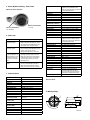
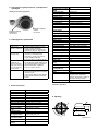
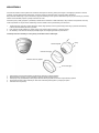
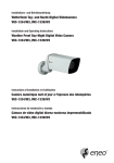
1
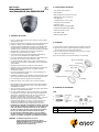
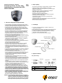
Montage und Betriebsanleitung
2. Allgemeine Beschreibung
1/3” Tag/Nacht-Domekamera
mit IR-Beleuchtung, Fix, VKCD-1325-B/IR
• Für Decken- und Wand-Aufbaumontage
• Vandalismusgeschützte Ausführung
• Varifokal-Objektiv F1,2/3,8-9,5mm mit DC-Blende
• Zoom/Fokus Einstellung von außen zugänglich
• Einschwenkbarer IR-Sperrfilter
• Empfindlichkeit 0,1Lux bei F1,2 (Farbe)
• Gegenlichtkompensation (BLC)
• Flackerfrei Ein/Aus
• Automatischer Weißabgleich (AWB)
• IR Beleuchtung: 25 integrierte 850nm LEDs
• Manuelle 3-Achsen Kameraausrichtung
• Betriebsspannung 12VDC
• Kugeldurchmesser 96mm
1. Sicherheitshinweise
• Bevor Sie das System anschließen und in Betrieb nehmen, lesen Sie zuerst diese Sicherheitshinweise und die Betriebsanleitung.
• Bewahren Sie die Betriebsanleitung sorgfältig zur späteren Verwendung auf.
•
Die Kameras gegen Eindringen von Wasser und Feuchtigkeit schützen, Wasser kann die Geräte dauerhaft schädigen. Sollte dennoch Feuchtigkeit eingedrungen sein, die Kameras nie unter diesen Bedingungen einschalten, sondern zur Überprüfung an eine autorisierte Fachwerkstatt geben.
• Das System darf nie außerhalb der technischen Daten benutzt werden, das kann die Kamera zerstören.
• Die Kamera nur in einem Temperaturbereich von -10°C bis +50°C und einer
Luftfeuchtigkeit bis max. 90% betreiben.
3. Installation
1) Gehäusebasis mit den mitgelieferten Schrauben an der gewünschten Stelle
befestigen.
2) Gewünschte Blickrichtung durch Drehen und Bewegen der Eyeball-Kamera
einstellen und mit dem Fixierring feststellen.
3) Dome-Abdeckring auf die Gehäusebasis setzen und von Hand im Uhr-
zeigersinn festdrehen.
4) Zum Fixieren des Dome-Abdeckrings die Befestigungsschraube verwenden.
• Um das System von der Versorgungsspannung zu trennen, ziehen Sie das Kabel nur am Stecker heraus. Ziehen Sie nie direkt am Kabel.
Gehäusebasis
• Verlegen Sie die Verbindungskabel sorgfältig und stellen Sie sicher, dass die Kabel nicht mechanisch beansprucht, geknickt oder beschädigt werden und keine Feuchtigkeit eindringen kann.
Montageschrauben
• Versuchen Sie nicht, das Kameramodul aus dem Dome auszubauen.
Eyeball-Kamera
• Das Gerät darf nur von qualifiziertem Servicepersonal geöffnet werden. Fremdeingriffe beenden jeden Garantieanspruch.
• Die Kamera darf nie mit geöffneter Blende gegen die Sonne gerichtet werden (Zerstörung des Sensors).
Fixierring
• Montage, Wartung und Reparaturen dürfen nur von autorisiertem Fachpersonal
ausgeführt werden. Vor Öffnen des Gehäuses ist eine Netztrennung erforderlich.
Dome-Abdeckring
• Falls Funktionsstörungen auftreten, benachrichtigen Sie bitte Ihren Lieferanten.
Befestigungsschrauben
• VerwendenSienurOriginal-Ersatzteileu.-Zubehörvon.
• Zur Reinigung der Gehäuse immer nur ein mildes Haushaltsmittel verwenden. Niemals Verdünner oder Benzin benutzen, dies kann die Oberfläche dauer-
haft schädigen.
• Es müssen alle zur Montage vorgesehenen Öffnungen im Gehäuse ge-
schlossen, bzw. abgedichtet werden.
•
Es lässt sich nicht vermeiden, dass im Rahmen der Fertigung und auch beim späteren Gebrauch in gewissem Umfang Feuchtigkeit der Umgebungs-
luft im Gehäuse vorhanden ist. Bei starken Temperaturschwankungen kann sich die Feuchtigkeit im Gehäuse niederschlagen.
4. Spannungsversorgung
12VDC
Um dies in dem sehr dicht abschließenden Gehäuse zu vermeiden, hat der Hersteller Silicagel-Beutel in das Kameragehäuse eingelegt.
1
Es ist eine physikalische Gegebenheit, dass diese Silicagel-Beutel nach einer gewissen Zeit eine Sättigung erreichen. Sie sollten deshalb gegen neue Silicagel-Beutel ausgetauscht werden.
2
• Der Errichter ist für die Aufrechterhaltung der Schutzart lt. Techn.
Daten verantwortlich, z.B. durch Verwendung aller beiliegenden Dichtungen und O-Ringen, durch Abdichtung des Kabelaustritts mit Silikon
oder durch Verlegen des Kabels in einer Weise, dass durch das Kabel
keine „Wasserrinne” entsteht.
• Bei der Montage muss grundsätzlich darauf geachtet werden, dass
vorhandene Dichtungen ordnungsgemäß eingesetzt und bei der
Montage nicht verschoben werden. Beschädigte Dichtungen dürfen
nicht mehr verbaut werden.
HINWEIS: Dies ist ein Gerät der Klasse A. Dieses Gerät kann im Wohnbereich Funktionsstörungen verursachen; in diesem Fall kann
vom Betreiber verlangt werden, angemessene Maßnahmen
durchzuführen und dafür aufzukommen.
Nr.
1
2
Video / gelb
Videoausgang
Spannung / rot
GND
Funktion
Videoausgang
Spannungseingang
Anschlussfarbe
Gelb
Rot
12VDC (+)
GND
5. Externe Objektiveinstellung – Zoom / Fokus
IR-Sperrfilter
schaltbar, per Motor, automatisch (in Ab-
hängigkeit von der einfallenden Licht-
menge). Im ausgeschwenkten Zustand wird
das Farbsignal abgeschaltet
nein
nein
nein
Varifokal
3,8mm - 9,5mm
74,2° - 30°
0,15 m
Objektiv mit variabler Brennweite
6. Fehlersuche
Das Bild auf dem Bildschirm ist zu blass.
Die Kamera arbeitet nicht
richtig, die Oberfläche des
Kameragehäuses ist heiß,
und auf dem Bildschirm
erscheint eine schwarze
Linie.
Der Bildschirm blinkt
häufig.
Lösung
• Überprüfen Sie die Spannungsversorgung von
Monitor und Kamera und stellen Sie sicher, dass Spannung und Polarität stimmen und die Leitungen auch stromführend sind.
• Prüfen Sie, ob das Objektiv verschmutzt ist. Bei Verschmutzung das Objektiv mit einem weichen, sauberen Tuch reinigen.
•
•
•
Auflagemaß des Objektivs neu einstellen.
Prüfen Sie, ob die Kamera an die richtige Spannungsversorgung angeschlossen ist. Wenn kein Problem mit der Spannungsver-
sorgung besteht, schalten Sie die Kamera sofort aus und wenden Sie sich an den Kundendienstvon.
Prüfen Sie, ob die Kamera auf die Sonne oder eine Leuchtstofflampe gerichtet ist.
• Winkel oder Anbringungsort der Kamera ändern, wenn zu viel Licht auf sie gelangt.
7. Technische Daten
Typ
Art.-Nr.
System
Videonorm
Chipgröße
Aufnahmesensor
Aktive Bildelemente
Horizontale Auflösung
Synchronisation
Signal-/Rauschabstand
Gamma-Korrektur
Lichtempfindlichkeit
(bei 50% Videosignal)
Automatische Verstärkungsregelung (AGC)
Low Speed Shutter
Digitale Rauschunterdrückung (DNR)
Gegenlichtkompensation
Wide Dynamic Range (WDR)
Weißabgleich
Apertur-Korrektur (APC)
VKCD-1325B-/IR
92597
Tag/Nacht
PAL
1/3”
CCD, Sony Super HAD Interline Transfer
440.000 (H) 752 x (V) 582
600 TVL
intern
50dB (AGC ausgeschaltet)
0,45
0,1 Lux, (Farbe); 0,05Lux (SW) bei F1,2
(gemessen)
vorhanden
Optionales Zubehör
8. Maßzeichnungen
90
nein
nein
nein
nein
automatisch
horizontal, vertikal
34
Problem
Auf dem Bildschirm
erscheint kein Bild.
90.5
Fern / nah
Tele / Weitwinkel
F1,2 ~ F260
Zoom/Fokus
Composite (FBAS), 1Vss, FBAS, 75Ohm
–
–
nein
360°
infrarot, 25x LEDs 850nm / 30°. Durch den
integrierten Lichtsensor wird die LED-Beleuchtung ein-/ausgeschaltet (abhängig von
der Umgebungsbeleuchtung)
Lichtsensor
nein
Externe Anschlüsse
Video (BNC), Spannungseingang
Steuer-Schnittstellen
nein
Gehäuse
Außen
Gehäusematerial
Aluminium
Farbe (Gehäuse)
anthrazit
Heizung
nein
Montageart
Wandmontage, Deckenmontage
Betriebsspannung
12VDC (+/-10%)
Leistungsaufnahme
5W
Temperaturbereich (Betrieb) -10°C ~ +50°C
Schutzart
IP66
Vandalismusgeschützt
ja
Abmessungen
siehe Maßzeichnung
Gewicht
870g
Lieferumfang
Domekamera, Befestigungsbeipack,
Inbusschlüssel, DC-Kabel mit offenen
Enden, Bohrschablone, Betriebsanleitung,
Spezialschlüssel zur Objektivverstellung
Zertifizierungen
CE
63
Externe Fokuseinstellung
Externe Zoom-Einstellung
Bewegungsmelder
Digital Zoom
Analysefunktionen
Objektiv Typ
Brennweite
Bildwinkel horizontal
MOD
(Minimum Object Distance)
Blendenbereich (F)
Externe Einstellungen
Videoausgänge
Alarmeingänge
Alarmausgänge
PTZ Unterstützung
Drehbereich
Beleuchtung
120
ϒ
Maße: mm
HINWEIS
Da es sich nicht immer vermeiden lässt, dass im Rahmen der Fertigung und auch beim späteren Gebrauch in gewissem Umfang Feuchtigkeit der Umgebungsluft in das
Gehäuse eindringen kann, hat der Hersteller Silicagel-Beutel in das Kameragehäuse eingelegt.
Dass diese Silicagel-Beutel nach einer gewissen Zeit eine Sättigung erreichen, ist eine physikalische Gegebenheit und auch ein normaler Vorgang, der durch den
Austausch gegen neue Silicagel-Beutel behoben werden sollte.
Beim Austausch ist darauf zu achten, dass die Silicagel-Beutel sachgerecht verwandt werden. D.h. ein zu frühes Öffnen der Schutz-folie kann zur Sättigung des Silicagels in sehr kurzer Zeit führen und es damit wirkungslos machen.
1. Bitte vor dem Einlegen des Silicagel-Beutels die Schutzhülle (Alu) um den Beutel entfernen, denn nur ohne Aluschutzhülle kann das Silicagel seine Wirkung entfalten.
2. Die 2 Silicagel-Beutel lose zwischen Gehäuseteil und Kameraträger einlegen.
3. Das Silicagel kann dann wieder die Restfeuchtigkeit entziehen, die ggf. in das Gehäuse gelangt ist.
Anleitung zum Öffnen des Gehäuses zum Austausch der Silicagel-Beutel:
Schrauben
Eyeball-Kamera
Fixierring
Dome-Abdeckring
Befestigungsschraube
1. Die Befestigungsschraube (Madenschraube) am Abdeckring lösen und den Abdeckring abschrauben.
2. Den Fixierring abnehmen und das Eyeball-Kameraelement aus der Gehäusebasis herausnehmen.
3. Die 3 Schrauben (Kreuzschlitz) an der unteren Schale des Eyeball Kameraelementes lösen und die beiden Eyeball-Gehäuseteile auseinander ziehen.
4. Die 2 Silicagel-Beutel entnehmen und 2 neue / unverbrauchte - wie oben beschrieben - einlegen.
5. Die Kamera wieder montieren.
Installation and Operating Instructions
2. General Description
1/3” Day/Night Dome Camera
with LED Illumination,Fixed, VKCD-1325B-/IR
• For wall and ceiling flush and surface mount
• Vandal and tamper-resistant
• Integrated F1.2/3.8-9.5mm Varifocal DC iris lens
• Externally adjustable Focus and Zoom
• Removable IR cut filter
• Sensitivity of 0.1Lux at F1.2 (colour)
• Backlight compensation (BLC)
• Flickerless On/Off
• Automatic White Balance (AWB)
• IR illumination by 25 integrated 850nm LEDs
• Manual 3-axis camera gimbal
• Supply Voltage: 12VDC
• Ball eye size 96mm
1. Safety Instructions
• Read these safety instructions and the operation manual first before you install and commission the camera.
• Keep the manual in a safe place for later reference.
3. Installation
•
1) Fix the base housing to the desired place with screws supplied.
Protect your camera from contamination with water and humidity to prevent
it from permanent damage. Never switch the camera on when it gets wet. Have it checked at an authorized service center in this case.
• Never operate the camera outside of the specifications as this may prevent the camera functioning.
• Do not operate the cameras beyond their specified temperature, humidity or
power ratings.
2) Adjust desired scene by turning and moving the eyeball camera and fix it with stopping ring.
3) Put the dome cover over the base housing and turn it clockwise by hand.
4) To fix dome cover tide, use mounting screw.
• Operate the camera only at a temperature range of -10°C to +50°C and at a humidity of max. 90%.
base housing
mounting screw
• To disconnect the power cord of the unit, pull it out by the plug. Never pull the cord itself.
Eyeball camera
• Pay attention when laying the connection cable and observe that the cable is not subject to heavy loads, kinks, or damage and no moisture can get in.
• Do not attempt to disassemble the camera board from the dome.
stopping ring
• The warranty becomes void if repairs are undertaken by unauthorized persons. Do not open the camera housing.
• Never point the camera towards the sun with the aperture open. This can destroy the sensor.
dome cover
• Installation, maintenance and repair have to be carried out only by authorized service centers. Before opening the cover disconnect the unit from mains input.
fixing screw
• Contact your local dealer in case of malfunction.
• Onlyuseoriginalpartsandoriginalaccessoriesfrom.
• Do not use strong or abrasive detergents when cleaning the dome. Use a dry cloth to clean the dome surface.
In case the dirt is hard to remove, use a mild detergent and wipe gently.
• All openings provided in the housing for assembly purposes must be closed and/or sealed.
•
It is unavoidable that, during manufacturing and also during subsequent use, the moisture contained in ambient air is, to some extent, present in the housing. With strong temperature variations, the moisture may develop condensation within the housing.
In order to avoid this in the tightly locked housing, the manufacturer has inserted silica gel bags inside the camera.
It is a physical fact that these silica gel bags do reach saturation after a while. They must therefore be replaced with new silica gel bags.
• The installer is responsible for ensuring that the degree of protection
as per the technical specifications is upheld, e.g. by using all enclosed
gasket seals and O-rings, by waterproofing the cable exits with silicon
or through laying the cable in such a way that the cable does not act
as a „gutter”.
• During assembly, care must be taken to ensure that existing seals are
correctly inserted and are not displaced as a result of assembly.
You must not continue to use damaged seals.
NOTE: This is a class A digital device. This digital device can cause
harmful interference in a residential area; in this case the user
may be required to take appropriate corrective action at his/her
own expense.
4. Power connection
12VDC
1
2
No.
1
2
Function
video output
power input
Video / yellow
Video output
Power / red
GND
Terminal Colour
yellow
red
12VDC (+)
GND
5. Composition External Lens Adjustment of Zoom / Focus
IR cut filter
switchable, motorized, switchable filter.
Automatic function depend on the amount
of light. In removed filter position, the
colour signal will be switched OFF
no
no
no
varifocal
3.8 mm - 9.5 mm
74.2° - 30°
0.15 m
Varifocal lens type
6. Troubleshooting
Problem
The image does not
appear on the screen.
The image on the screen
is dim.
Solution
• Check the power source for the monitor and camera and assure that the voltage and polarity are properly connected and being supplied correctly.
• Check if the lens is stained. If dirty, clean the lens with a soft, clean cloth.
The camera does not work
properly, the surface of the
camera case is hot, and a
black line appears on the
•
•
The screen blinks a lot.
Adjust the Back Focus of the lens again.
Check if you have connected the camera to a proper power source and if there is no problem with the power, turn the unit off immediately and seek assistance from • Check if the camera is pointed towards the sun or a fluorescent lamp.
• Adjust the angle or location of the camera if too much light is coming into the screen.
7. Specifications
Type
Art. No.
System
Video standard
Sensor size
Imager
Active picture elements
Horizontal resolution
Synchronization
Signal-to-noise ratio
Gamma correction
Sensitivity
(at 50% video signal)
Automatic gain control (AGC)
Low speed shutter
Digital Noise Reduction (DNR)
Backlight compensation
Wide Dynamic Range (WDR)
White balance
Aperture Correction (APC)
VKCD-1325-B/IR
92597
day&night
PAL
1/3”
CCD, Sony Super HAD Interline Transfer
440,000 (H) 752 x (V) 582
600 TVL
internal
50dB (AGC OFF)
0.45
0.1 Lux, (colour), 0.05Lux (B&W) at F1.2
(measured)
supplied
no
no
no
no
automatic
horizontal, vertical
Light sensor
External connections
Serial interfaces
Housing
Housing material
Colour (housing)
Heater
Mounting
Supply voltage
Power consumption
Temperature range
(operation)
Protection rating
Vandalism resistant
Dimensions
Weight
Parts supplied
IP66
yes
see drawing
870g
dome camera, bag of screws, allen
key, DC cable with open ends, drilling
template, manual, special key for lens
adjustment
CE
Certificates
Optional Accessories
8. Dimensional Drawings
90
90.5
Tele / Wide
F1.2 ~ F260
zoom and focus
composite (CVBS), 1Vp-p, CVBS, 75ohms
–
–
no
360°
infrared, 25x IR LED (850nm, 30°). Due to an integrated light sensor the LED
illumination will be switched ON/OFF,
depending on environmental illumination
conditions.
no
video (BNC), voltage input
no
outdoor
aluminium
anthracite
no
wall mount, ceiling mount
12VDC (+/-10%)
5W
-10°C ~ +50°C
63
Far / Near
External Zoom Adjustment
34
External Focus Adjustment
Activity detection
Digital zoom
Analysis Functions
Lens type
Focal length
Horizontal angle of view
MOD
(Minimum object distance)
Aperture range (F)
External adjustments
Video outputs
Alarm inputs
Alarm outputs
PTZ support
Rotation range
Illumination
120
ϒ
Dimensions: mm
NOTICE
Since the penetration of a certain amount of moisture from the ambient air into the housing during fabrication as well as during subsequent use cannot be entirely
avoided, the manufacturer has put silica gel bags into the camera housing.
After some time, these silica gel bags will become saturated. This is a normal physical process and should be addressed by replacing them with new silica gel bags.
During replacement, ensure that the silica gel bags are handled properly. Opening the protective film prematurely can lead to rapid saturation of the silica gel, thereby
rendering it ineffective.
1. Before inserting the silica gel bag, remove the protective cover (aluminium) from the bag. The silica gel will only be effective after the protective aluminium cover has been removed.
2. Loosely insert the 2 silica gel bags between the housing component and camera mount.
3. Now the silica gel can once again absorb residual moisture that may penetrate the housing.
Instructions for opening the housing to replace the silica gel bags:
Screws
Eyeball camera
Fixation ring
Dome cover ring
Mounting screw
1. Loosen the mounting screw (set screw) on the cover ring and unscrew the cover ring.
2. Take off the fixation ring and remove the eyeball camera element from the housing base.
3. Loosen the 3 screws (Phillips) on the bottom cup of the eyeball camera element and pull the two eyeball housing components apart.
4. Remove the 2 silica gel bags and insert 2 new, unused bags as described above.
5. Reinstall the camera.
Mode d’emploi
2. Caractéristiques Principales
Dôme couleur jour/nuit 1/3”
avec illumination IR, fixe, VKCD-1325-B/IR
• Pour montage mural ou plafond
• Anti-vandalisme
• Objectif intègrè avec focal variè F1,2/3,8-9,5
• Règlage externe de focus et du Zoom
• Filtre IR pivotant
• Sensibilitè 0,1Lux pour F1,2 (couleur)
• Compensation contre-jour (BLC)
• Règlage de l’acuitè
• Balance des blancs automatique (AWB)
• Illumination IR (25 DELs intègrè, 850nm)
• Alignement manuel sur 3 axes
• Alimentation 12VDC
• Diamétre de boule 96mm
1. Consignes de sécurité
•
•
•
•
•
•
•
•
•
•
•
•
•
Lisez ces consignes de sécurité et la notice avant de raccorder le système et de la mettre en service.
Conserver soigneusement le mode d’emploi, il peut vous servir ultérieurement.
Protéger les caméras contre les infiltrations d’eau et d’humidité qui pourraient endommager durablement les appareils. Si de l’humidité s’était cependant infiltrée, ne jamais mettre les caméras sous tension dans ces conditions et les faire contrôler par un atelier de service après-vente qualifié.
Ne jamais utiliser le système sans tenir compte des spécifications techniques car cela pourrait détériorer la caméra.
La caméra ne doit fonctionner que dans une plage de températures de -10°C à +50°C et une humidité de l’air maximale de 90%.
Pour couper l’alimentation du système, débrancher le câble uniquement au niveau de la prise. Ne jamais tirer directement sur le câble.
Lors du branchement des câbles, veiller à ce qu’ils ne subissent pas de charge, qu’ils ne soient pas pliés ou endommagés et qu’ils soient protégés contre l’humidité.
Ne jamais essayer de démonter le module de la caméra du dôme.
L’appareil ne peut être ouvert que par un personnel de service après-vente qualifié. Toute intervention d’une personne non habilitée entraînera l’annulation de la garantie.
La caméra ne doit jamais être dirigée vers le soleil si le diaphragme est ouvert (cela détériorerait le capteur).
L’installation, la maintenance et les réparations sont réservées à des ateliers agréés. L’appareil doit être déconnecté du secteur avant d’ouvrir le boîtier.
En cas de dysfonctionnements, informez-en votre fournisseur.
N’utiliser que des pièces de rechange et des accessoires d’origine de •
•
•
•
Utiliser uniquement des produits d’entretien doux pour nettoyer l’appareil.
Ne jamais employer de dissolvant ou d’essence, sous peine de détériorer irrémédiablement la surface.
Toutes les ouvertures prévues pour le montage au niveau du boîtier doivent être fermées, respectivement étanchéifiées.
Il n’est pas possible d’éviter que, dans une certaine mesure, de l’humidité de l’air ambiant se trouve dans le boîtier dans le cadre de la fabrication et également lors de l’utilisation ultérieure. En cas de fortes variations de températures, l’humidité peut se condenser dans le boîtier.
Afin d’éviter cela dans le boîtier fermant de façon hermétique, le fabricant a déposé des sachets de gel de silice dans le boîtier de la caméra.
Il existe une donnée physique, à savoir que ces sachets de gel de silice atteignent une saturation après un certain temps. Ils devraient par conséquent être remplacés par de nouveaux sachets de gel de silice.
L’installateur est responsable de la maintenance de l’indice de protection
selon les données techniques, par exemple lors de la mise en place des
joints et des anneaux compris dans la livraison, lors du calfeutrage
des câbles en sortie avec du silicon ou lors de la pose des câbles de
façon à ce qu ’aucune rigole ne se forme au travers des câbles.
• Lors du montage, il est impératif de veiller à ce que les garnitures
existantes soient placées correctement et ne glissent pas pendant le
montage. Les garnitures endommagées ne doivent plus être utilisées.
REMARQUE: Cet équipement appartient à la classe A.
Il peut provoquer des dysfonctionnements dans les
bâtiments d’habitation; dans ce cas, l’utilisateur est tenu
de mettre en oeuvre, le cas échéant, les mesures
appropriées et d’en assumer le coût.
3. Installation
1) Fixez le boîtier de la base à l’emplacement voulu à l’aide des vis fournies.
2) Ajustez la scène voulue en tournant et déplaçant la caméra en forme de globe oculaire et fixez-la à l’aide de l’anneau de butée.
3) Placez le couvercle dôme sur le boîtier de la base et tournez-le à la main dans le sens des aiguilles d’une montre.
4) Pour fixer fermement le couvercle dôme, utilisez les vis de montage.
base de la caméra dôme
vis de montage
caméra en forme de globe oculaire
anneau de butée
Couvercle de protection
vis de fixation
4. Connexion de l’alimentation
12VDC
1
2
No.
1
2
vidéo / jaune
sortie vidéo
alimentation / rouge
terre
Fonction
sortie vidéo
entrée alimentation
Couleur de connexion
jaune
rouge
12VDC (+)
terre
5. Réglage externe du zoom et de la mise au point de la lentille
Filtre IR
Filtre coupure IR
Type de lentille à foyer progressif
Réglage externe du zoom
Réglage externe de la mise
au point
Télé / Grand angle
Loin / Près
Entrées alarmes
Sorties alarme
Support PTZ
Plage de rotation
Illumination
6. Dépannage
La caméra ne fonctionne
pas correctement, la
surface de la caméra
est chaude et une ligne
noire apparaît à l’écran.
L’écran clignote beaucoup.
•
•
•
Réglez à nouveau la mise au point arrière.
Assurez-vous que la caméra est branchée à une source d’alimentation adaptée. S’il n’y a aucun problème d’alimentation, désactivez immédiatement l’unité et contactez le support techniquede.
La caméra est-elle exposée directement à la lumière du jour ou à un lumière fluorescente ?
• Modifiez l’angle ou l’emplacement de la camé-
ra si la lumière est trop abondante sur l’écran.
7. Spècifications
IP66
oui
voir croquis
870g
caméra dôme, kit de fixation, clé alêne,
câble DC avec extrémités ouvertes, plan
de percage, mode d’emploi, clé spéciale
pour objectif ajustement
CE
Certificats
VKCD-1325-B/IR
92597
jour&nuit
PAL
1/3”
CCD, Sony Super HAD Interline Transfer
440,000 (H) 752 x (V) 582
600 lignes TV
interne
50dB (AGC éteint)
0,45
0,1 Lux, (couleur); 0,05Lux (N&B) par F1,2 (mesuré)
disponible
Accessoires en option
8. Croquis
90
63
Modèle
No. d’article
Système
Norme vidéo
Dimension du capteur
Capteur
Eléments d’image actifs
Résolution horizontale
Synchronisation
Rapport signal-bruit
Correction gamma
Sensibilité à la lumière
(50% de signal vidéo)
Réglage automatique de gain
(CAG)
Low speed shutter
Suppression du bruit
numérique (DNR)
Correction de contre-jour
Wide Dynamic Range (WDR)
Balance des blancs
Correction d’ouverture (APC)
Connexions externes
Interfaces de commande
Caisson
Matériau
Couleur (caisson)
Chauffage
Mode de montage
Alimentation
Consommation
Gamme de température
(fonctionnement)
Indice de protection
Anti-vandalisme
Dimensions
Poids
Contenu de la livraison
90.5
L’image à l’écran est
sombre.
Solutions
• Vérifiez la source d’alimentation de l’écran et de la caméra et assurez-vous que la connexion
et l’alimentation de la tension et la polarité sont correctes.
• Regardez si la lentille n’est pas tachée. Si elle est sale, nettoyez-la avec un chiffon doux et propre.
non
non
34
Problème
L’image n’apparaît pas
à l’écran.
Détecteur d’activité
Zoom numérique
Fonctions d’analyse
Type de l’objectif
Focale
Angle d’image horizontal
Distance objet minimale (MOD)
Ouverture (F)
Réglages externes
Sorties vidéo
commutable
Par moteur, automatique (dépendemment de la luminosité). Par pivot, le signal couleur s´éteint.
non
non
non
focale variable
3,8 mm - 9,5 mm
74,2° - 30°
0,15 m
F1,2 ~ F260
zoom et focus
composite (FBAS), 1Vcc, composite,
75Ohm
–
–
non
360°
infrarouge, 25x DEL, IR (850nm, 30°).
Par le senseur de lumière, les DEL seront
mise en /hors service, dépendemment
du pegel de luminosité.
vidéo (BNC), entrée de alimentation
non
extérieur
aluminium
anthracite
non
montage mural, montage plafond
12VDC (+/-10%)
5W
-10°C à +50°C
120
non
non
automatique
horizontale, verticale
ϒ
Dimensions: mm
REMARQUE
Comme il n’est pas toujours possible d’éviter la pénétration d’humidité dans le boîtier lors de la fabrication et au cours de l’utilisation, le fournisseur a inséré des
sachets de gel de silice dans le boîtier de la caméra.
Le fait que ces sachets de gel de silice arrivent à saturation après un certain temps est un processus physique et normal qui requiert le remplacement par de nouveaux
sachets de gel de silice.
Lors du remplacement, il convient de veiller à les utiliser correctement car une ouverture trop précoce du film de protection peut entraîner très rapidement la saturation
du gel de silice et le rendre ainsi inefficace.
1. Avant d’insérer le sachet de gel de silice, enlever l’enveloppe de protection (aluminium) qui entoure le sachet car le gel de silice ne peut agir que si l’enveloppe en
aluminium a été retirée.
2. Insérer les deux sachets de gel de silice entre l’élément du boîtier et le support de la caméra.
3. Le gel de silice peut alors absorber l’humidité résiduelle éventuellement présente dans le boîtier.
Instructions pour ouvrir le boîtier afin de remplacer les sachets de gel de silice:
Vis
Caméra en forme de globe oculaire
Anneau de butée
Couvercle de protection
Vis de fixation
1. Dévisser la vis de fixation (vis sans tête) du couvercle de protection, puis dévisser le couvercle de protection.
2. Retirer l’anneau de butée et dégager la caméra en forme de globe oculaire du boîtier.
3. Dévisser les trois vis (cruciformes) à l’arrière de la caméra et séparer les deux éléments du boîtier.
4. Retirer les deux sachets de gel de silice et insérer les deux nouveaux sachets tel que décrit ci-dessus.
5. Remonter la caméra.
Instrukcja instalacji i obsługi
Kamera kopułowa 1/3 cala, stała,
tryb dzień/noc i oświetleniem LED,
VKCD-1325-B/IR
2. Opis ogólny
•
•
•
•
•
•
•
•
•
•
•
•
•
Do montażu natynkowego i podtynkowego na ścianie i suficie
Obudowa odporna na akty wandalizmu i demontaż
Wbudowany obiektyw zmiennoogniskowy z przesłoną prądu stałego F1.2/3,8–9,5mm
Możliwość regulacji ostrości i powiększenia z zewnątrz
Filtr podczerwieni z możliwością demontażu
Czułość 0,1 luksa przy F1.2 (kolor)
Kompensacja tylnego oświetlenia (BLC)
Możliwość włączenia/wyłączenia trybu redukcji migotania
Automatyczny balans bieli (AWB)
25 wbudowanych diod LED zapewnia podświetlenie w podczerwieni (850nm)
Trójosiowe zawieszenie kardanowe do ręcznej regulacji kamery
Napięcie zasilania: 12V prądu stałego
Rozmiar kopuły obiektywu: 96mm
1. Zalecenia dotyczące bezpieczeństwa
•
•
•
•
•
•
•
•
•
•
•
•
•
•
•
•
•
•
Przed instalacją i rozpoczęciem użytkowania kamery należy przeczytać poniższą instrukcję dotyczącą bezpieczeństwa i obsługi.
Instrukcję należy przechowywać w bezpiecznym miejscu.
Kamerę należy chronić przed wodą i wilgocią, która może spowodować trwałe uszkodzenia. Nie wolno włączać kamery, gdy jest wilgotna. W takim przypadku powinna zostać sprawd-
zona przez autoryzowany punkt serwisowy.
Nie wolno użytkować kamery poza zakresem jej parametrów technicznych, ponieważ może to uniemożliwić jej działanie.
Nie wolno użytkować kamery poza wyznaczonymi zakresami temperatury, wilgotności i parametrów zasilania.
Kamera powinna być używana tylko w temperaturze od -10°C do +45°C i przy wilgotności poniżej 80%.
Przy odłączaniu przewodu zasilania należy ciągnąć za wtyczkę.
Nie wolno ciągnąć za przewód.
Należy starannie układać przewód połączeniowy, zwracając uwagę, żeby nie był silnie obciążony, załamany, uszkodzony ani narażony na działanie wilgoci.
Nie wolno demontować układu kamery z jej kopuły.
W przypadku przeprowadzania napraw przez nieupoważnione osoby gwarancja przestaje obowiązywać.
Nie wolno otwierać obudowy kamery.
Nie wolno zwracać kamery w kierunku słońca przy otwartej przysłonie. Może to spowodować zniszczenie czujnika.
Instalacja, prace konserwacyjne i naprawy mogą być wykony-
wane wyłącznie przez autoryzowane punkty serwisowe.
Przed zdjęciem pokrywy konieczne jest odłączenie urządzenia od zasilania.
W przypadku awarii należy skontaktować się z lokalnym sprzedawcą.
Należy używać wyłącznie oryginalnych części i oryginalnych akcesoriówdostarczanychprzezfirmę.
Do czyszczenia kopuły nie wolno stosować silnych ani ściernych detergentów. Powierzchnię kopuły należy przecierać suchą szmatką. W przypadku zabrudzeń trudniejszych do usunięcia można użyć łagodnego detergentu i delikatnie przetrzeć powierzchnię.
Wszystkie otwory w obudowie przeznaczone do montażu należy zamknąć i/lub uszczelnić.
W procesie produkcji oraz podczas późniejszego użytkowania nieuniknione jest występowanie w obudowie urządzenia pewnej
ilości wilgoci obecnej w powietrzu otoczenia. Przy znacznych wahaniach temperatury wilgoć ta może skraplać się wewnątrz obudowy.
Aby uniknąć takiej sytuacji, w bardzo szczelnie zamykanej obudowie kamery producent umieścił w niej pochłaniacze wilgoci.
Po pewnym czasie pochłaniacze wilgoci osiągają stan nasycenia – jest to ich właściwość fizyczna. Dlatego torebki z silikażelem należy wymieniać na nowe.
Instalator jest odpowiedzialny za zapewnienie odpowiedniego zabezpieczenia zgodnie z danymi technicznymi, np.
przez wykorzystanie wszystkich dołączonych uszczelek i
pierścieni o-ring, zabezpieczenie wyjść przewodów przed
wodą za pomocą silikonu lub poprzez ułożenie kabla w taki
sposób, aby nie zbierała się przy nim woda.
• Podczas montażu należy zwrócić szczególną uwagę na to,
żeby uszczelki były poprawnie umieszczone i żeby się nie
przesunęły w trakcie składania urządzenia.
Nie wolno używać uszkodzonych uszczelek.
UWAGA: Jest to urządzenie cyfrowe klasy A. To urządzenie
cyfrowe może powodować powstawanie szkodliwych
zakłóceń w obszarach mieszkalnych. W takim przypadku użytkownik może być zmuszony do podjęcia
właściwych działań naprawczych na własny koszt.
3. Instalacja
1) Przymocuj obudowę podstawy w żądanym miejscu przy użyciu śrub z zestawu.
2) Ustaw żądane pokrycie sceny, obracając i przesuwając kamerę
kopułową. Następnie zablokuj ją pierścieniem mocującym.
3) Umieść pokrywę kopuły nad obudową podstawy i obróć ją zgodnie z ruchem wskazówek zegara.
4) Przykręć mocno pokrywę kopuły śrubą mocującą.
obudowa podstawy
śruba mocująca
kamera kopułowa
pierścień mocujący
pokrywa kopuły
śruba mocująca
4. Złącze zasilania
12V prądu stałego
1
2
Nr
1
2
Wideo/żółty
Zasilanie/
czerwony
Funkcja
Wyjście wideo
Wejście zasilania
Wyjście wideo
Masa
Kolor złącza
Żółty
Czerwony
12V prądu
stałego (+)
Masa
5. Zewnętrzna regulacja ostrości i powiększenia
obiektywu
Obiektyw o zmiennej ogniskowej
Zewnętrzna regulacja
ostrości
Daleko/blisko
Zewnętrzna regulacja
powiększenia
Tele/szeroki kąt
6. Rozwiązywanie problemów
Problem
Rozwiązanie
• Sprawdź źródło zasilania monitora i Obraz nie jest widoczny na ekranie. kamery, a także prawidłowe podłączenie kabli z uwzględnieniem parametrów zasilania i biegunowości.
• Sprawdź, czy obiektyw nie jest zanie-
Obraz na ekranie jest niewyraźny.
czyszczony. Jeśli obiektyw jest zabrudzony, oczyść go za pomocą czystej, miękkiej ściereczki.
• Ponownie ustaw tylną głębię ostrości.
• Sprawdź, czy kamera jest podłączona Kamera nie działa
do prawidłowego źródła zasilania i czy prawidłowo, powierzchnia obudowy nie występują problemy z zasilaniem. kamery jest gorąca, a Natychmiast wyłącz urządzenie i na ekranie widoczna zwróć się o pomoc do firmy jest czarna linia.
Ekran miga.
• Sprawdź, czy kamera nie jest zwrócona w kierunku słońca lub lampy
fluorescencyjnej.
• Jeśli na ekran pada zbyt dużo światła, zmień ustawienie kąta lub położenie kamery.
Kompensacja światła
Szeroki zakres dynamiki
(WDR)
Wyrównanie bieli
Korekta apertury (APC)
Filtr IR
Detekcja ruchu
Zoom cyfrowy
Funkcje analizy
Typ obiektywu
Ogniskowa
Kąt widzenia poziomy
Minimalna odległość
obiektu (MOD)
Zakres przysłony (F)
Regulacja zewnętrzna
Wyjścia video
Wejścia alarmowe
Wyjście alarmowe
Wsparcie PTZ
Zakres obrotu
Oświetlenie
Złącza zewnętrzne
Interfejs szeregowy
Obudowy
Materiał obudowy
Kolor obudowy
Ogrzewanie
Sposób montażu
Zasilanie
Pobór mocy
Zakres temperatur
pracy
Klasa szczelności
Ochrona
wandaloodporna
Wymiary
Waga
W ramach dostawy
Certyfikaty
automatyczny
pozioma, pionowa
mechaniczny
nie
nie
nie
ze zmienną ogniskową
3,8 mm - 9,5 mm
74,2° - 30°
0,15 m
F1,2 ~ F260
zoom/fokus
BNC, 1Vp-p, CVBS, 75ohms
–
–
nie
360°
IR
video (BNC), wejście zasilania
nie
zewnętrzna
aluminium
antracytowy
nie
montaż ścienny, montaż sufitowy
12VDC (+/-10%)
5W
-10° ~ +50°C
IP66
tak
patrz rysunek
870g
kamera kopułkowa, zestaw
mocujący, imbus, kabel DC z
otwartymi końcówkami, szablon do
wiercenia, instrukcja obsługi
CE
Akcesoria opcjonalne
8. Wymiary
90.5
90
34
VKCD-1325-B/IR
92597
dzień/noc
PAL
1/3”
CCD
Sony Super HAD Interline Transfer
440.000 (H) 752 x (V) 582
600 TVL
wewnętrzna
50dB (ARW wyłączone)
63
7. Dane techniczne
Typ
Nr art.
System
Standard wideo
Przekątna sensora
Typ przetwornika
Typ sensora
Efektywna liczba pikseli
Rozdzielczość pozioma
Synchronizacja
Odstęp sygnału do
szumu
Korekcja Gamma
Czułość światła (przy
50% sygnału video)
Automatyczna kontrola
wzmocnienia (AGC)
Wolna przysłona
Cyfrowa redukcja
szumów
nie
nie
0,45
0,1 Lux (kolor); 0,05 luks (czarno-biały) przy F1,2
w dostawie
nie
nie
120
ϒ
Wymiary w mm
WSKAZÓWKA
Ponieważ nie zawsze można wyeliminować możliwość wniknięcia do obudowy pewnej ilości wilgoci z otaczającego powietrza w ramach
produkcji i podczas późniejszego użytkowania, producent umieścił w obudowie kamery woreczki z żelem silikatowym.
Nasycenie żelu silikatowego w tych woreczkach po upływie określonego czasu wynika z właściwości fizycznych i jest normalnym procesem,
któremu można zaradzić poprzez wymianę woreczków na nowe.
Podczas wymiany należy pamiętać o prawidłowym zastosowaniu woreczków z żelem silikatowym. Zbyt wczesne usunięcie folii ochronnej
może doprowadzić do nasycenia żelu silikatowego w bardzo krótkim czasie i pozbawienia go skuteczności.
1.
2.
3.
Przed włożeniem woreczka z żelem silikatowym należy zdjąć powłokę ochronną (aluminiową) wokół niego, ponieważ żel silikatowy może skutecznie działać tylko bez tej powłoki.
Dwa woreczki z żelem silikatowym należy włożyć luzem między element obudowy i wspornik kamery.
Żel silikatowy może wówczas wchłonąć pozostałą wilgoć, która mogła zgromadzić się w obudowie.
Instrukcja otwierania obudowy w celu wymiany woreczków z żelem silikatowym:
Śruby
Kamera Eyeball
Pierścień mocujący
Pierścień osłonowy kopułki
Śruba mocująca
1.
2.
3.
4.
5.
Poluzuj śrubę mocującą (zamykającą) na pierścieniu osłonowym i odkręć pierścień.
Zdejmij pierścień mocujący i wyjmij z podstawy obudowy element kamery Eyeball.
Poluzuj trzy śruby (krzyżakowe) w dolnej części elementu kamery Eyeball i rozsuń obie części obudowy Eyeball.
Wyjmij dwa woreczki z żelem silikatowym i włóż dwa nowe/nieużywane zgodnie z powyższym opisem.
Ponownie zamontuj kamerę.