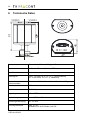
1
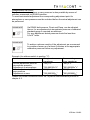
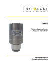
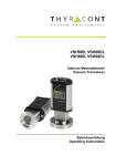
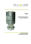
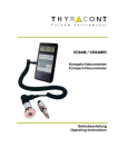
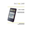
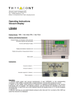
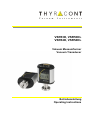
VSR53D, VSR53DL VSR54D, VSR54DL Vakuum Messumformer Vacuum Transducer Betriebsanleitung Operating Instructions 2 Inhalt 1 2 3 4 5 6 Hinweise für Ihre Sicherheit....................................................... 3 Vakuum Messumformer VSR ..................................................... 4 2.1 Zur Orientierung...................................................................... 4 2.2 Lieferumfang........................................................................... 4 2.3 Produktbeschreibung .............................................................. 4 Installation .................................................................................. 5 3.1 Hinweise zur Installation ......................................................... 5 3.2 Vakuumanschluss ................................................................... 5 3.3 Elektrischer Anschluss ............................................................ 7 3.3.1 Anschluss an Thyracont Anzeigegeräte............................ 7 3.3.2 Kundeneigene Spannungsversorgung.............................. 8 Betrieb ........................................................................................ 9 4.1 Allgemeines ............................................................................ 9 4.2 Kommunikation ......................................................................10 4.2.1 Die serielle Schnittstelle des VSR ...................................10 4.2.2 Kommunikationsprotokoll ................................................11 4.2.3 Befehlsübersicht .............................................................11 4.3 Bedienung des VSR...............................................................13 4.4 Nachjustieren.........................................................................14 4.5 Gasart-Korrekturfaktoren .......................................................17 4.6 Schaltpunkte ..........................................................................18 4.7 Modus Wertangleichung ........................................................19 Wartung und Service .................................................................20 Technische Daten ......................................................................22 Konformitätserklärung ......................................................................24 Hersteller: Thyracont Vacuum Instruments GmbH Max Emanuel Straße 10 D 94036 Passau Tel.: ++49/851/95986-0 Fax.: ++49/851/95986-40 email: [email protected] Internet: http://www.thyracont.com VSR-de-130422 3 1 Hinweise für Ihre Sicherheit Lesen und befolgen Sie alle Punkte dieser Anleitung Informieren Sie sich über Gefahren, die vom Gerät ausgehen und Gefahren, die von Ihrer Anlage ausgehen Beachten Sie die Sicherheits- und Unfall-Verhütungsvorschriften Prüfen Sie regelmäßig die Einhaltung aller Schutzmaßnahmen Installieren Sie das VSR unter Einhaltung der entsprechenden Umgebungsbedingungen; die Schutzart ist IP40, d.h. die Geräte sind geschützt gegen Eindringen von Fremdkörpern Beachten Sie beim Umgang mit den verwendeten Prozessmedien die einschlägigen Vorschriften und Schutzmaßnahmen Berücksichtigen Sie mögliche Reaktionen zwischen Werkstoffen und Prozessmedien Berücksichtigen Sie mögliche Reaktionen der Prozessmedien infolge der Eigenerwärmung des Produkts Gerät nicht eigenmächtig umbauen oder verändern Informieren Sie sich vor Aufnahme der Arbeiten über eine eventuelle Kontamination Beachten Sie im Umgang mit kontaminierten Teilen die einschlägigen Vorschriften und Schutzmaßnahmen Legen Sie beim Einsenden des Gerätes eine Kontaminationsbescheinigung bei Geben Sie die Sicherheitsvermerke an andere Benutzer weiter Piktogramm-Definitionen Gefahr von Personenschäden Gefahr von Schäden an Gerät oder Anlage Wichtige Information über das Produkt, dessen Handhabung oder den jeweiligen Teil der Betriebsanleitung, auf den besonders aufmerksam gemacht werden soll VSR-de-130422 4 2 Vakuum Messumformer VSR 2.1 Zur Orientierung Diese Betriebsanleitung ist gültig für Produkte mit den Artikelnummern VSR53D, VSR53DL, VSR54D und VSR54DL. Sie finden die Artikelnummern auf dem Typenschild. Technische Änderungen ohne vorherige Anzeige sind vorbehalten. 2.2 Lieferumfang Zum Lieferumfang gehören: Messumformer VSR Staubschutzkappe Betriebsanleitung Lieferbares Zubehör: Messkabel 2m für Anzeigegerät VD9, W1506002 Messkabel 6m für Anzeigegerät VD9, W1506006 Messkabel 2m für Anzeigegerät VD10/VD12, W1515002 Messkabel 6m für Anzeigegerät VD10/VD12, W1515006 Gegenstecker SubD 15polig, XB1500002 2.3 Produktbeschreibung Der Vakuum Messumformer VSR dient zur Absolutdruck-Messung im Bereich -4 1200 - 1x10 mbar. Das Gerät kann an ein Thyracont Anzeigegerät angeschlossen oder gemäß Anschlussbelegung mit einer kundeneigenen Spannungsversorgung betrieben werden. Das analoge Mess-Signal 1,5V - 8,58V ist dabei über den gesamten Messbereich logarithmisch vom Druck abhängig. Zusätzlich besitzt das Gerät eine RS485 Schnittstelle zur digitalen Datenübertragung (siehe Kapitel 4.2). Das Gerät ist mit einem metallgedichteten Kombinationssensor des Typs Piezo / Pirani ausgerüstet und temperaturkompensiert. Es kann an geeignete Flanschverbindungen angeschlossen werden. VSR-de-130422 5 Bestimmungsgemäße Verwendung Das VSR dient ausschließlich der Absolutdruckmessung im Bereich -4 1200 - 1x10 mbar. Es darf nur an geeignete und hierfür vorgesehene Komponenten angeschlossen werden. Nicht bestimmungsgemäße Verwendung Als nicht bestimmungsgemäß gilt der Einsatz zu Zwecken, die von oben genannten abweichen, insbesondere: der Anschluss an Geräte oder Komponenten, die laut ihrer Betriebsanleitung hierfür nicht vorgesehen sind der Anschluss an Geräte, die berührbare, Spannung führende Teile aufweisen. Bei nicht bestimmungsgemäßem Einsatz erlischt jeglicher Haftungs- und Gewährleistungsanspruch Die Verantwortung im Zusammenhang mit den verwendeten Prozessmedien liegt beim Betreiber. 3 3.1 Installation Hinweise zur Installation Keine eigenmächtigen Umbauten oder Veränderungen am Gerät vornehmen! Aufstellungsort: Innenräume Für nicht vollklimatisierte Betriebsräume gilt: Temperatur: +5°C ... +60°C Rel. Luftfeuchte: max. 80% bis 30°C, max. 50% bei 40°C, nicht betauend Luftdruck: 860 - 1060 hPa 3.2 Vakuumanschluss Schmutz und Beschädigungen, insbesondere am Flansch, beeinträchtigen die Funktion dieses Gerätes. Beachten Sie bitte die beim Umgang mit Vakuumkomponenten erforderlichen Regeln in Bezug auf Sauberkeit und Schutz vor Beschädigung. VSR-de-130422 6 - Staubschutzkappe entfernen (wird bei Instandhaltungsarbeiten wieder benötigt!) - Vakuumanschluss über Kleinflansch DN16 ISO KF (VSR53) oder DN16CFFlansch (VSR54) herstellen - Bei Verbindung über Kleinflansch Metall-Spannelemente verwenden, die sich nur mit einem Werkzeug öffnen und schließen lassen (z.B. SpannbandSpannring), Dichtringe mit Zentrierring verwenden - Sicherstellen, dass der Sensorflansch mit dem Schutzleiter verbunden ist, beispielsweise durch metallischen Kontakt zur geerdeten Vakuumkammer (metallische Spannelemente) Die Einbaulage ist frei wählbar, jedoch kann eine Montage von unten, d.h. mit nach oben gerichtetem Flansch, zu vorzeitiger Verschmutzung und Ausfall des Geräts führen. Zu bevorzugen ist der Einbau von oben, d.h. mit nach unten gerichtetem Flansch, damit sich Staub und Kondensat nicht in der Messzelle ansammeln können. Der Messumformer ist in dieser Lage ab Werk justiert. Das Gerät beim Einbau nicht gewaltsam verdrehen, dies kann zur mechanischen Beschädigung führen! Bei Überdruck im Vakuumsystem > 1 bar Versehentliches Öffnen von Spannelementen kann zu Verletzungen durch herumfliegende Teile führen! Ungesicherte Schlauchverbindungen können sich lösen und Gesundheitsschäden durch ausströmende Prozessmedien herbeiführen! Bei Überdruck im Vakuumsystem 1,5 bis 4 bar Bei KF-Flanschverbindungen können Elastomer-Dichtringe dem Druck nicht mehr standhalten. Dies kann zu Gesundheitsschäden durch ausströmende Prozessmedien führen. VSR-de-130422 7 3.3 3.3.1 Elektrischer Anschluss Anschluss an Thyracont Anzeigegeräte Wird der Messumformer an einem Thyracont Anzeigegerät betrieben, ist ein geeignetes Messkabel zu verwenden (siehe Zubehör). Anschluss des Messumformers niemals mit Spannung führendem Kabel herstellen! Stecker am Messumformer einstecken und mit Schrauben sichern. Gegenüberliegenden Stecker am Anzeigegerät anstecken und sichern. Erst danach Spannungsversorgung am Anzeigegerät herstellen bzw. einschalten. VSR-de-130422 8 3.3.2 Kundeneigene Spannungsversorgung Der Messumformer kann auch mit anderen Anzeigegeräten oder kundeneigener Spannungsversorgung betrieben werden. Die elektrische Verbindung ist unter Verwendung geeigneter Kabel EMV-gerecht gemäß untenstehender Pinbelegung herzustellen: 8 15 1 9 Stecker Typ SubD, 15polig, männlich Pin 1: Pin 2: Pin 3: Pin 4: Pin 5: Pin 6: Pin 7: Pin 8: Pin 9: Pin 10: Pin 11: Pin 12: Pin 13: Pin 14: Pin 15: Identifikation: 22 kΩ Signal Output 0-10 VDC AGND Voltage Supply 24 VDC Supply GND Relay A, N.O. Relay A, Common Relay A, N.C. RS485 + RS485 Shield Relay B, N.O. Relay B, Common Relay B, N.C. Wir empfehlen, Abschirmung (Pin 12) und Speisungserde (Pin5) beim Speisegerät mit Erdung zu verbinden. Falscher Anschluss oder unzulässige Versorgungsspannung können zu Schäden am Messumformer führen. VSR-de-130422 9 4 Betrieb 4.1 Allgemeines Messprinzip Der Vakuum Messumformer VSR besitzt eine interne Kombination aus einem piezoelektrischen Membransensor und einem Piranisensor, der die Wärmeleitfähigkeit von Gasen zur Vakuummessung nutzt. Unter Einwirkung des Druckes verformt sich die dünne Membran des Piezosensors, auf deren Rückseite eine Widerstands-Messbrücke aufgebracht ist. Die dabei auftretende Verstimmung der Messbrücke ist ein Maß für den auf die Membran wirkenden Absolutdruck Beim Wärmeleitungssensor wird ein Wendel-Filament in einer Wheatstone Brückenschaltung auf eine konstante Temperatur aufgeheizt. Die notwendige Brückenspannung ist ein Maß für den Absolutdruck. Ausgangssignal Das Mess-Signal 1,5 - 8,58 V des VSR ist über den gesamten Messbereich von -4 1x10 - 1200 mbar logarithmisch vom Druck abhängig. Die Umrechnung erfolgt gemäß folgendem Zusammenhang: Vout /V = log (p/mbar) + 5,5 p /mbar = 10 (Vout /V – 5,5) Serielle Schnittstelle RS485 Der gemessene Druckwert kann über die serielle RS485 Schnittstelle des Messumformers digital ausgelesen werden. Darüber hinaus können verschiedene Parameter wie Gasart-Korrekturfaktoren programmiert werden. Weitere Informationen hierzu finden sie im Abschnitt 4.2 Kommunikation. Stabilisierungszeit Die Ausgabe des Mess-Signals erfolgt direkt nach Einschalten des Geräts. Zur Ausnutzung der vollen Genauigkeit des VSR kann es -insbesondere nach extremen Drucksprüngen- angebracht sein, eine Stabilisierungszeit von 5 min zu beachten. Messgenauigkeit Das Gerät ist ab Werk in stehender Position bei einer Versorgungsspannung von 24VDC abgeglichen. Verschmutzung, Alterung, extreme klimatische Bedingungen oder andere Einbaulagen können ein Nachjustieren erforderlich machen. -2 Die Messgenauigkeit kann daher unterhalb von 10 mbar reduziert sein. VSR-de-130422 10 Gasartabhängigkeit Das Mess-Signal ist im Druckbereich unterhalb 15 mbar gasartabhängig. Das Gerät ist auf N2 bzw. trockene Luft abgeglichen. Für andere Gase können via RS485 Korrekturfaktoren für den Piranisensor gesetzt werden, so dass unterhalb 0,1 mbar eine korrekte Druckausgabe resultiert (siehe Abschnitt 4.2 bzw. 4.5). 4.2 4.2.1 Kommunikation Die serielle Schnittstelle des VSR Der Messumformer VSR verfügt über eine serielle Schnittstelle RS485. Um die Kommunikation über RS485 zu aktivieren, ist zunächst der Gummistopfen über dem Adress-Schalter zu entfernen (1) und anschließend der Adress-Schalter mit einem dünnen Schraubendreher oder ähnlichem Hilfsmittel auf einen Wert zwischen 1 und 16 einzustellen (2). Danach den Gummistopfen wieder einsetzen. Die Kommunikation erfolgt gemäß Thyracont Protokoll, ausführliche Detailinformationen hierzu finden Sie in einer gesonderten Beschreibung. Der analoge Signalausgang 0-10V steht gleichzeitig zur RS485 zur Verfügung! VSR-de-130422 11 4.2.2 Kommunikationsprotokoll Die Kommunikation erfolgt gemäß Thyracont-Protokoll. Die Befehle werden in folgendem Rahmen als Zeichenfolge im ASCII-Code übertragen: Address Code Data cks CR Address: 3 Bytes, dezimal; Adressraum RS485: 001 – 999 Code: 1 Byte, Befehlsparameter, Großbuchstaben für Lesen, Kleinbuchstaben für Schreiben Data: Datenfeld, max. 6 Bytes; kann je nach Code auch fehlen cks: 1 Byte, Checksumme, definiert als Summe über alle Bytes der Felder Addresse, Code und Data, modulo 64 plus 64. CR: Carriage Return (0Dh, 13d) Datenformate: BOOLEAN STRING: UNSIGNED INT: FLOAT: 1 Byte max. 6 Bytes 6 Bytes mit führenden Nullen 6 Bytes, Exponentialformat 4 Bytes Mantisse (entspricht Mantissenwert x 1000) 2 Bytes Exponent, Offset 20 FLOAT-Werte werden in hPa (mbar) übertragen! -3 Beispiel: Der Wert "460017" in einem Float-Datenfeld steht für 4.6x10 mbar. Schnittstellen-Parameter: 9,6 / 14,4 / 19,2 / 38,4 / 57,6 / 115,2 kBd, 8 Datenbits, 1 Stopbit, keine Parität Nach dem Einschalten startet der Transmitter mit 9,6 kBd. Empfängt er Anfrage-Telegramme mit einer anderen Baudrate, so stellt sich der Transmitter automatisch darauf ein. Für diese automatische Baudraten-Erkennung benötigt er maximal zwei Telegramme der Sorte "Typanfrage" oder "Messwertanfrage". 4.2.3 Befehlsübersicht Der Messumformer reagiert auf Typanfragen, Messwertanfragen, Justierbefehle (Abschnitt 4.4) und Befehle zum Setzen von Gasart-Korrekturfaktoren (Abschnitt 4.5). Die Programmierung der beiden Relais-Schaltpunkte des VSR ist ebenfalls via RS485 möglich (Abschnitt 4.6). Darüber hinaus lassen sich Parameter konfigurieren, die das Verhalten der Sensorik bestimmen (Abschnitt 4.7). VSR-de-130422 12 Befehlsübersicht: Befehlstyp Typ Code T Datentyp STRING Messwert Schaltpunkt M S, s FLOAT FLOAT Gasart-Korrekturfaktor C, c UNSIGNED INT Modus Wertangleichung Druckjustierwert W, w UNSIGNED INT Funktion lesen (VSR: VSR205) lesen lesen S, schreiben s (VSR: SP1 und SP2) lesen C, schreiben c (VSR: C1 für Pirani) lesen W, schreiben w j FLOAT schreiben Beispiele (für Adress-Schalterstellung "1"): Aktion Typ lesen Telegramm an Messumformer C "001Te R" Antwort-Telegramm vom Messumformer C "001TVSR205w R" Messwert lesen "001M^ R" Schaltpunkt 2 lesen "001S2V R" Unlock Schaltpunkt 2 "001s2v R" Schaltpunkt 2 auf 4.2x10⁻³ mbar setzen Unlock Gasart-Korrekturfaktor 1 "001s420017r R" Gasart-Korrekturfaktor 1 auf 1.20 setzen Unlock Justierpunkt für Atmosphärendruck Justieren auf Atmosphärendruck "001c000120W R" C C "001M260017N R" ( 2.6x10⁻³ mbar) C "001S400016O R" ( 4.0x10⁻⁴ mbar) C "001s2v R" C C C C C "001s420017r R" C "001c1e R" "001c1e R" C C C "001c000120W R" C "001j1l R" "001j1l R" C "001j100023a R" C "001j100023a R" Vor dem Schreiben der Parameter "c" (Korrekturfaktor), "s" (Schaltpunkt) und "j" (Justierpunkt) müssen diese zunächst mit einem Unlock-Befehl freigeschaltet werden! VSR-de-130422 13 4.3 Bedienung des VSR Das VSR besitzt eine Status-LED, die folgende Betriebszustände signalisiert: Normalbetrieb / Pirani (grün - Dauerleuchten) Normalbetrieb / Piezo (grün - langsames Blinken) Fehler (rot - Dauerleuchten) Bereit zum Nachjustieren (orange - langsames Blinken) Initialisiere Nachjustieren (orange - schnelles Blinken) Die Modelle VSR53DL und VSR54DL verfügen zudem über eine gelb hinterleuchtete LCD Anzeige. Diese zeigt den aktuell gemessenen Ist-Druck. Liegt ein Fehler im Betrieb des Messumformers vor, wird dies durch ein rot hinterleuchtetes Display signalisiert. Zum Ändern der Anzeigeeinheit (mbar, Torr, hPa) während die Spannungsversorgung angeschlossen wird die Adj Taste gedrückt halten bis die Anzeige "Unit" erscheint. Dann die gewünschte Einheit durch Drücken der Adj Taste auswählen. Nach 5 s ohne weiteren Tastendruck wird die Einstellung gespeichert. VSR-de-130422 14 4.4 Nachjustieren Das Gerät ist ab Werk bei Versorgungsspannung 24V stehend, d.h. mit dem Flansch nach unten, abgeglichen. Andere Einbaulagen, Einsatz unter anderen klimatischen Bedingungen, extreme Temperaturschwankungen, Alterung oder Verschmutzung können ein Nachjustieren erforderlich machen. Nachjustieren am Gerät Für den Pirani-Sensor ist ein Nachjustieren auf Atmosphärendruck oder Nulldruck digital über den Taster "ADJ" möglich (siehe Bedienschema unten). Der Messumformer erkennt automatisch, um welchen Justierpunkt es sich handelt. -5 Beim Nullabgleich sollte der Ist-Druck kleiner 5,0x10 mbar sein. Um optimale Ergebnisse beim Nachjustieren zu erzielen, empfehlen wir vor jedem Abgleich eine Warmlaufphase von mindestens 5 Minuten beim jeweiligen Kalibrierdruck zu beachten. Zum Justieren den Gummistopfen über dem Taster "ADJ" entfernen (1), dann mit einem dünnen Schraubendreher oder ähnlichem Hilfsmittel kurz auf den Taster drücken (2), bis die Status-LED schnell orange zu blinken beginnt. Nach 3s ohne weiteren Tastendruck signalisiert langsames Blinken, dass der Transmitter nun nachjustiert werden kann. Hierzu nochmals kurz die Taste drücken. Gummistopfen nun wieder einsetzen. VSR-de-130422 15 Status LED grün Normalbetrieb / Piezo Status LED grün Normalbetrieb / Pirani Status LED schnell blinkend Set langsam blinkend Dauerleuchten Status LED orange Initialisiere Nachjustieren Set Status LED grün Normalbetrieb 3s Status LED orange Justieren 10s grün Set Automatische Justierung von Nulldruck oder Atmosphärendruck Pirani 1s grün Status LED grün Normalbetrieb Status LED grün Normalbetrieb Status LED rot 3s Justierfehler Status LED grün Normalbetrieb VSR-de-130422 16 Nachjustieren über RS485 Ein Nachjustieren auf Atmosphärendruck oder Nulldruck ist auch durch entsprechende Software-Befehle über die RS485 Schnittstelle möglich. Per RS485 werden sowohl Pirani als auch Piezosensor justiert. Zum Abgleich auf Atmosphärendruck wird daher ein kalibriertes Druckmessgerät als Referenz benötigt! -5 Beim Nullabgleich sollte der Ist-Druck kleiner 5,0x10 mbar sein. Um optimale Ergebnisse beim Nachjustieren zu erzielen, empfehlen wir vor jedem Abgleich eine Warmlaufphase von mindestens 5 Minuten beim jeweiligen Kalibrierdruck zu beachten. Um unbeabsichtigtes Justieren des Messumformers zu verhindern, muss der jeweilige Justierpunkt für Atmosphärendruck bzw. Nulldruck zunächst freigeschaltet werden, danach kann die eigentliche Justierung erfolgen. Beispiel für Adress-Schalterstellung "1": Aktion Telegramm an Antwort-Telegramm Messumformer vom Messumformer C C Unlock Justierpunkt für "001j1l R" "001j1l R" Atmosphärendruck C C Justieren auf Atmosphärendruck "001j985022u R" "001j985022u R" C C Unlock Justierpunkt für "001j0k R" "001j0k R" Nulldruck C C Justieren auf Nulldruck "001j000000[ R" "001j000000[ R" Weitere Informationen zum Thyracont-Kommunikationsprotokoll finden Sie in Abschnitt 4.2. VSR-de-130422 17 4.5 Gasart-Korrekturfaktoren Das Mess-Signal des VSR ist im Druckbereich unter 15 mbar gasartabhängig. Das Gerät ist ab Werk auf N2 bzw. trockene Luft abgeglichen. Für andere Gase kann die Druckausgabe unterhalb 0,1 mbar korrigiert werden, indem Korrekturfaktoren für den Piranisensor via RS485 gesetzt werden. Die Messwerte des Sensors werden dann bereits im Gerät jeweils mit den entsprechenden Korrekturfaktoren multipliziert, so dass am analogen und digitalen Ausgang des Messumformers ein korrigiertes Mess-Signal zur Verfügung steht. Korrekturfaktor 1 Pirani: Ar 1,6 CO2 CO 1,0 H2 Address Address: Code: Data: cks: CR: Code 0,89 0,57 He N2 Data 1,0 1,0 cks Ne Kr 1,4 2,4 CR 3 Bytes, dezimal; Adressraum RS485: 001 – 999 "C" zum Lesen, "c" zum Schreiben des Korrekturfaktors Leseanfrage oder Unlock: 1 Byte; "1" für Korrekturfaktor Pirani, Wert lesen oder schreiben: 6 Byte; unsigned int 1 Byte, Checksumme definiert als Summe über alle Bytes der Felder Address, Code und Data, modulo 64 plus 64. Carriage Return (0Dh, 13d) Der Wert des Datenfeldes beim Lesen oder Schreiben des Korrekturfaktors beinhaltet führende Nullen und entspricht dem 100fachen des Korrekturfaktors. Wertebereich: "000020" für 0.20 bis "000800" für 8.00 Beispiel für Adress-Schalterstellung "1": Aktion Telegramm an Messumformer C Gasart-Korrekturfaktor 1 lesen "001C1E R" Unlock Gasart-Korrekturfaktor 1 C "001c1e R" C Antwort-Telegramm vom Messumformer C "001C000240z R" c1=2.40 C "001c1e R" C Gasart-Korrekturfaktor 1 "001c000057` R" "001c000057` R" auf 0,57 setzen Weitere Informationen zum Thyracont-Kommunikationsprotokoll finden Sie in Abschnitt 4.2. VSR-de-130422 18 4.6 Schaltpunkte Das VSR besitzt 2 unabhängige, potentialfreie Relais-Schaltpunkte. Diese sind als Umschalter gemäß der in Abschnitt 3.3.2 beschriebenen Pinbelegung am Anschluss-Stecker nach außen geführt. Die Schalter sind jeweils bei Druckwerten unterhalb der zugehörigen Sollwerte aktiv und es leuchten die entsprechenden Kontroll-LEDs auf der Steckerseite des VSR. Die Schalthysterese ist fest auf 30% vom Sollwert eingestellt. Die Programmierung der beiden Sollwerte erfolgt via RS485-Schnittstelle. Address Address: Code: Data: cks: CR: Code Data cks CR 3 Bytes, dezimal; Adressraum RS485: 001 – 999 "S" zum Lesen, "s" zum Schreiben des Sollwerts Leseanfrage oder Unlock: 1 Byte; "1" für Schaltpunkt 1 / Relais A, "2" für Schaltpunkt 2 / Relais B Wert lesen oder schreiben: 6 Byte; float 1 Byte, Checksumme definiert als Summe über alle Bytes der Felder Address, Code und Data, modulo 64 plus 64. Carriage Return (0Dh, 13d) Beispiel für Adress-Schalterstellung "1": Aktion Telegramm an Messumformer C Schaltpunkt 2 lesen "001S2V R" Unlock Schaltpunkt 2 C "001s2v R" C Antwort-Telegramm vom Messumformer C "001S400016O R" ( 4.0x10⁻⁴ mbar) C "001s2v R" C Schaltpunkt 2 auf "001s420017r R" "001s420017r R" 4.2x10⁻³ mbar setzen Weitere Informationen zum Thyracont-Kommunikationsprotokoll finden Sie in Abschnitt 4.2. VSR-de-130422 19 4.7 Modus Wertangleichung Im VSR erfolgt standardmäßig ein kontinuierlicher Übergang zwischen Piezound Piranibereich. Dabei findet eine Wertangleichung statt. Um das Verhalten des Messumformers den Prozessanforderungen optimal anzupassen, können mit dem Parameter "Modus Wertangleichung" per RS485 folgende Optionen konfiguriert werden: 0: keine Wertangleichung, d.h. hartes Umschalten zwischen Piezo und Pirani bei 1,0 mbar Wertangleichung im Bereich 5,0 bis 15 mbar (Standard) 1: Address Address: Code: Data: cks: CR: Code Data cks CR 3 Bytes, dezimal; Adressraum RS485: 001 – 999 "W" zum Lesen, "w" zum Schreiben des Parameters 6 Bytes; "000001" Wertangleichung, "000000" harte Umschaltung 1 Byte, Checksumme definiert als Summe über alle Bytes der Felder Address, Code und Data, modulo 64 plus 64. Carriage Return (0Dh, 13d) Beispiel für Adress-Schalterstellung "1": Aktion Telegramm an Messumformer C Modus Wertangleichung setzen "001w000001i R" auf Wertangleichung C Modus Wertangleichung lesen "001Wh R" Antwort-Telegramm vom Messumformer C "001w000001i R" C "001W000001I R" ( Wertangleichung) Weitere Informationen zum Thyracont-Kommunikationsprotokoll finden Sie in Abschnitt 4.2. VSR-de-130422 20 5 Wartung und Service Vorsicht bei kontaminierten Teilen! Es kann zu Gesundheitsschäden kommen. Informieren Sie sich vor Aufnahme der Arbeiten über eine eventuelle Kontamination. Beachten Sie beim Umgang mit kontaminierten Teilen die einschlägigen Vorschriften und Schutzmaßnahmen. Das Gerät ist wartungsfrei. Äußerliche Verschmutzungen können mit einem feuchten Tuch beseitigt werden. Sollte wider Erwarten ein Schaden an Ihrem VSR auftreten, senden Sie das Gerät bitte mit einer ausgefüllten Kontaminationserklärung (siehe nächste Seite) zur Reparatur an uns. Das Gerät ist nicht zur kundenseitigen Reparatur vorgesehen! Defekte Sensorköpfe können vor Ort ausgetauscht werden (Ersatzteile B_VSR53 bzw. B_VSR54). Fehlfunktionen des Gerätes, die auf Verschmutzung oder Verschleiß zurückzuführen sind, fallen nicht unter die Gewährleistung. Fehlersignal und Störungen Problem Mögliche Ursache Behebung Messwertabweichung zu groß Alterung, Verschmutzung, extreme Temperaturen, falsche Justierung Nachjustieren Messbereich unterschritten (Druck < 1x10 mbar) Gerät oder Sensor defekt Gerät einschicken Code unbekannt gesendeten TelegrammCode prüfen Bearbeitung des gesendeten Befehls ist momentan nicht möglich Gerät einschicken 0,5V < Mess-Signal < 1,3V/ "000000" via RS485 Mess-Signal <0,5V / "1" via RS485 Status LED dauerrot "5" via RS485 "7" via RS485 logischer Fehler Nachjustieren des PiraniNullpunkts nicht möglich Messwertabweichung übersteigt den Justierbereich VSR-de-130422 -4 21 VSR-de-130422 22 6 Technische Daten VSR54 48 99 99 VSR53 C 69 30 Messprinzip Piezoresistiv / Wärmeleitfähigkeit Pirani Messbereich 1200 - 1x10 mbar (900 - 1x10 Torr) Max. Überlast 4 bar abs. Genauigkeit 1200 - 10 mbar: ca. 0,3 % f.s. (v. Skalenendwert) 10 - 0,002 mbar: 10 % f.r. (v. Messwert) Materialien mit Vakuumkontakt Reaktionszeit Edelstahl 1.4301, Wolfram, Nickel, Glas, Gold, SiO2 Betriebstemperatur 5...60 C Lagertemperatur -40...+65 C Ausheiztemperatur max. 125°C am Flansch Spannungsversorgung 20 - 30 VDC Leistungsaufnahme max. 2,5 W, zusätzlich 0,8 W für Relais und LCD VSR-de-130422 -4 -4 200 ms o o 23 Ausgangssignal 0 - 10 VDC, min. 10 kΩ Messbereich 1,5 - 8,58 VDC, logarithmisch Serielle Schnittstelle RS485: 9,6 … 115 kBd, 8 databit, 1 stopbit, no parity Schaltausgänge 2x Relais, potentialfrei 50 VAC / 2 A bzw. 30 VDC / 2 A, max. 60 VA Elektrischer Anschluss Sub-D, 15-polig, männl., verschraubbar Vakuumanschluss VSR53: Kleinflansch DN16 ISO KF VSR54: Conflat Flansch DN16 CF Abmessungen 109 x 69 x 48 mm (VSR53) Schutzart IP 40 Gewicht 195 g (VSR53) VSR-de-130422 24 Konformitätserklärung VSR-de-130422 25 Content 1 2 3 4 5 6 Safety Instructions ................................................................... 26 Vacuum Transducer VSR ......................................................... 27 2.1 For Orientation ...................................................................... 27 2.2 Delivery Content ................................................................... 27 2.3 Product Description............................................................... 27 Installation ................................................................................ 28 3.1 Notes for Installation ............................................................. 28 3.2 Vacuum Connection.............................................................. 28 3.3 Electrical Connection ............................................................ 30 3.3.1 Operation With Thyracont Display Unit ........................... 30 3.3.2 Operation With Other Supply And Evaluation Units ........ 31 Operation .................................................................................. 32 4.1 General................................................................................. 32 4.2 Communication ..................................................................... 33 4.2.1 The Serial Interface Of The VSR .................................... 33 4.2.2 Communication Protocol ................................................ 34 4.2.3 Survey of Commands..................................................... 34 4.3 Operating the VSR ................................................................ 36 4.4 Readjustment........................................................................ 37 4.5 Gas-Correction-Factors......................................................... 40 4.6 Switchpoints ......................................................................... 41 4.7 Mode Sensor Transition ........................................................ 42 Maintenance and Service ......................................................... 43 Technical Data .......................................................................... 45 Declaration of Conformity ................................................................ 47 Manufacturer: Thyracont Vacuum Instruments GmbH Max Emanuel Straße 10 D 94036 Passau Tel.: ++49/851/95986-0 Fax.: ++49/851/95986-40 email: [email protected] Internet: http://www.thyracont.com VSR-de-130422 26 1 Safety Instructions Read and follow the instructions of this manual Inform yourself regarding hazards, which can be caused by the product or arise in your system Comply with all safety instructions and regulations for accident prevention Check regularly that all safety requirements are being complied with Take account of the ambient conditions when installing your VSR. The protection class is IP 40, which means the unit is protected against penetration of foreign bodies. Adhere to the applicable regulations and take the necessary precautions for the process media used Consider possible reactions between materials and process media Consider possible reactions of the process media due to the heat generated by the product Do not carry out any unauthorized conversions or modifications on the unit Before you start working, find out whether any of the vacuum components are contaminated Adhere to the relevant regulations and take the necessary precautions when handling contaminated parts When returning the unit to us, please enclose a declaration of contamination Communicate the safety instructions to other users Pictogram-Definition Danger of personal injury! Danger of damage to the unit or system! Important information about the product, it's handling or about a particular part of the documentation, which requires special attention. VSR-de-130422 27 2 2.1 Vacuum Transducer VSR For Orientation This operating instructions describe installation and operation of products with article numbers VSR53D, VSR53DL, VSR54D and VSR54DL. The article number can be found on the product's type label. Technical modifications are reserved without prior notification. 2.2 Delivery Content Included in the delivery consignment are: Transducer VSR Protective flange cover Operating instructions Available Accessories: Measurement cable 2m for VD9 display unit, W1506002 Measurement cable 6m for VD9 display unit, W1506006 Measurement cable 2m for VD10/VD12 display unit, W1515002 Measurement cable 6m for VD10/VD12 display unit, W1515006 Counterplug 15pole, XB1500002 2.3 Product Description The VSR vacuum transducer is measuring total pressure in the range of -4 1200 - 1x10 mbar. The transducer can be connected to Thyracont display and control units or to customer related power supply and evaluation units in compliance with pin assignment. The analog output signal 1.5V - 8.58V has a logarithmic dependence on pressure over the whole range. In addition the device has a serial RS485 interface for digital data transfer (see chapter 4.2). The transducer is equipped with a metal-sealed combination sensor type Piezo / Pirani and temperature compensated. It can be mounted to suitable flange connectors. VSR-de-130422 28 Proper Use The VSR serves exclusively to provide absolute pressure measurements in the -4 range 1200 - 1x10 mbar. It may only be connected to components specifically provided for such purpose. Improper Use The use for purposes not covered above is regarded as improper, in particular: the connection to components not allowed for in their operating instructions the connection to components containing touchable, voltage carrying parts. No liability or warranty will be accepted for claims arising from improper use. The user bears the responsibility with respect to the used process media. 3 3.1 Installation Notes for Installation Unauthorized modifications or conversions of the instrument are not allowed! Installation location: Indoor For not fully air conditioned open buildings and operation rooms: Temperature: +5°C ... +60°C Rel. Humidity: max. 80% up to 30°C, max. 50% at 40°C, not condensing Air pressure: 860 - 1060 hPa 3.2 Vacuum Connection Dirt and damage, especially at the vacuum flange, have an adverse effect on the function of this vacuum component. Please take account of the necessary instructions with regard to cleanliness and damage prevention when using vacuum components. VSR-de-130422 29 - Remove the protective cover (is required again during maintenance work!) - Make vacuum connection via small flange DN16 ISO KF (VSR53) or conflat flange DN16CF (VSR54) - Use clamps, that can be opened and closed with appropriate tools only (e.g. strap retainer-tension-ring), use sealing rings with a centering ring - Make sure that the sensor flange is connected to ground, e.g. by having electrical contact to the grounded vacuum chamber (use metallic clamps) The transducer may be mounted in any orientation. Mounting with the flange to the top, however, can lead to early contamination and damage of the sensor. An upright orientation with flange to the bottom is to be preferred in order to keep particles and condensates out of the sensor cell. The transducer is adjusted in the upright position ex works. When mounting the transducer avoid forced twisting or violent opening. This can damage the VSR! Overpressure in the vacuum system > 1 bar Accidental or unintended opening of clamp elements under stress can lead to injuries due to parts flying around! Unsecured hose connections can release, process media thus can leak and possibly damage your health. Overpressure in the vacuum system 1.5 to 4 bar KF flange connections with elastomer sealings cannot withstand such pressures. Process media thus can leak and possibly damage your health. VSR-de-130422 30 3.3 3.3.1 Electrical Connection Operation With Thyracont Display Unit For operation of the transducer with a Thyracont display and control unit a suitable measurement cable must be used (see accessories). Do not connect or disconnect the transducer when the cable is on circuit! Connect the cables plug to the transducer and secure it with the screw. Connect the other end of the cable to the display unit and secure the plug. Only now connect your display unit to mains power or switch it on respectively. VSR-de-130422 31 3.3.2 Operation With Other Supply And Evaluation Units The transducer can be operated with other customer related display units or voltage supplies. The electrical connection is to be made by means of suitable cables considering EMI demands and according to the pin description shown below: 8 15 1 9 Socket Type SubD, 15pole, male Pin 1: Pin 2: Pin 3: Pin 4: Pin 5: Pin 6: Pin 7: Pin 8: Pin 9: Pin 10: Pin 11: Pin 12: Pin 13: Pin 14: Pin 15: Identification: 22 kΩ Signal Output 0-10VDC AGND Voltage Supply 24VDC Supply GND Relay A, N.O. Relay A, Common Relay A, N.C. RS485 + RS485 Shield Relay B, N.O. Relay B, Common Relay B, N.C. We recommend to have Shield (Pin 6) and supply common (Pin5) grounded in the supply unit. Incorrect connection or inadmissible supply voltage can damage the transducer. VSR-de-130422 32 4 Operation 4.1 General Measurement Principle The VSR vacuum transducer is equipped with an internal combination sensor of type Piezo / Pirani. Under the influence of pressure the thin diaphragm of the piezo-resistive sensor is bent, on its back a resistor-bridge is applied. The bending forces the measurement-bridge to come out of tune, which is a measure for the applied pressure. The Pirani principle uses the heat conduction of gases for measuring vacuum. A sensor filament in a Wheatstone circuit is heated to a constant temperature, so the bridge voltage is a measure for total gas pressure. Output Signal The output signal 1.5 - 8.58 V of your VSR has a logarithmic dependence on -4 pressure over the whole measurement range 1x10 - 1200 mbar. Conversion of voltage signal and pressure is done according to the following formula: Vout /V = log (p/mbar) + 5.5 p /mbar = 10 ( Vout /V – 5.5 ) Serial Interface RS485 The measured absolute pressure can be read out digitally via the transducers serial RS485 interface. Additionally you can set various parameters like gas correction factors or setpoints. For further information see chapter 4.2 communication. Warm-Up Time The signal output of VSR is available immediately after the unit is switched on. To take advantage of the maximum accuracy of the unit it is appropriate to allow for stabilization time of 2 minutes, especially when extreme pressure changes have occurred. Accuracy The unit is adjusted ex works in upright position and at 24V voltage supply. Through contamination, ageing, extreme climatic conditions or different mounting orientation the need for readjustment may arise. In accordance, the accuracy can -2 be reduced in the range below 10 mbar. VSR-de-130422 33 Dependence On Gas Type Below 15 mbar the output signal depends on composition and type of the gas being measured. The unit is adjusted for N2 and dry air. For other gases correction factors for the Pirani sensor can be set via RS485 (see chapter 4.2 and 4.5. This results in a correct pressure display below 0.1 mbar. 4.2 4.2.1 Communication The Serial Interface Of The VSR The VSR transducer is equipped with a serial RS485 interface. To enable communication via RS485 please remove the rubber cap over the address switch (1) and then set the address switch to a value between 1 and 15 using a small screw driver or a similar tool (2). Afterwards insert the rubber cap again. Communication is carried out according to the Thyracont protocol, detailed information hereto is provided in a separate description. The analog output signal 0-10V is simultaneously available when RS485 ! VSR-de-130422 34 4.2.2 Communication Protocol Communication is carried out according to the Thyracont protocol. The commands are sent as ASCII-code in the following command frame: Address Code Data cks CR Address: 3 Bytes, decimal; address space RS485: 001 – 999 Code: 1 Byte, command parameter, upper case character for read command, lower case character for write command Data: data field, max. 6 Bytes; can be absent depending on code cks: 1 Byte, checksum, defined as sum over all Bytes of the fields address, code and data, modulo 64 plus 64. CR: Carriage Return (0Dh, 13d) Data Formats: BOOLEAN STRING: UNSIGNED INT: FLOAT: 1 Byte max. 6 Bytes 6 Bytes with leading zeros 6 Bytes, exponential format 4 Bytes mantissa (means mantissa value x 1000) 2 Bytes exponent, offset 20 FLOAT-values are transmitted in hPa (mbar)! -4 Example: Value "460016" in a float type data field means 4.6x10 mbar. Interface-Parameter: 9,6 / 14,4 / 19,2 / 38,4 / 57,6 / 115,2 kBd, 8 data bits, 1 Stopbit, no parity When powered on the transducer starts with 9,6 kBd. If a telegram with different baud rate is received, the transducer will automatically adapt to it. For this automatic baud rate adaption a maximum of two telegrams of type "Type Request" or "Measurement Request" is required. 4.2.3 Survey of Commands The transducer responds to type queries, measurement queries, commands for adjustment (chapter 4.4) and for setting gas correction factors (chapter 4.5). Programming of the two relay switchpoints is also done via RS485 (chapter 4.6). Further special parameters can be configured, which determine the general behaviour of the sensors (chapter 4.7). VSR-de-130422 35 Survey of Commands: Command Type Code T Data Type STRING Measurement Value Setpoint M S, s FLOAT FLOAT Gas-Correction-Factor C, c UNSIGNED INT Mode Sensor Transition Pressure Adjustment W, w UNSIGNED INT Function read (VSR: VSR205) read read S, write s (VSR: SP1 and SP2) read C, write c (VSR: C1 for Pirani) read W, write w j FLOAT write Examples (for address-switch in position "1"): Action Read type Telegram to transducer C "001Te R" Answer telegram from transducer C "001TVSR205w R" Read pressure measurement "001M^ R" Read setpoint 2 "001S2V R" Unlock setpoint 2 "001s2v R" Set setpoint 2 to 4.2x10⁻³ mbar Unlock gas-correction-factor 1 "001s420017r R" Set gas-correction-factor 1 to 1.20 Unlock adjustment for atmosphere pressure Adjust on atmosphere pressure "001c000120W R" C C "001M260017N R" ( 2.6x10⁻³ mbar) C "001S400016O R" ( 4.0x10⁻⁴ mbar) C "001s2v R" C C C C C "001s420017r R" C "001c1e R" "001c1e R" C C C "001c000120W R" C "001j1l R" "001j1l R" C "001j100023a R" C "001j100023a R" Before writing the parameters "c" (correction factor), "s" (setpoint) and "j" (adjustment) you must activate them by sending the corresponding unlock command! VSR-de-130422 36 4.3 Operating the VSR The VSR is equipped with a status LED which signalizes the following operational states: Normal Operation / Pirani (green LED continuously on) Normal Operation / Piezo (green LED flashing slowly) Error (red LED continuously on) Ready for Adjustment (orange LED flashing slowly) Initializing Adjustment (orange LED flashing quickly) In addition models VSR53DL and VSR54DL have an LCD with yellow backlight, that displays the measured actual pressure. In case of an operation error or malfunction the display is illuminated by a red background color. In order to change the display unit (mbar, Torr, hPa) hold the Adj key pressed while connecting power supply until the display shows "Unit". Then select the desired unit by pressing the Adj key. After 5 seconds without further keypress the setting is saved. VSR-de-130422 37 4.4 Readjustment The transducer is adjusted ex works with 24V voltage supply in upright position, flange to the bottom. Other orientation, operation under different climatic conditions, extreme temperature changes, ageing or contamination can result in the need for readjustment. Readjustment by pushbutton For the Pirani sensor readjustment on atmosphere or zero pressure can be done by means of the ADJ pushbutton of the VSR (see operating scheme below). The transducer will notice automatically which adjustment point is relevant. For zero adjustment actual pressure should be less than -5 5,0x10 mbar. To achieve optimum results of the adjustment we recommend to consider a warm-up of at least 5 minutes at the appropriate calibration pressure before any adjustment. For adjustment first remove the rubber cap above the ADJ button (1), then press the pushbutton several times by means of a screwdriver or other suitable tool (2) until the status LED starts quickly flashing orange. After further 3s a slowly flashing status LED signalizes that the transducer now can be readjusted by pushing the button once again. Finally insert the rubber cap again. VSR-de-130422 38 Status LED green Normal Operation / Piezo Status LED green Normal Operation / Pirani Status LED flashing quickly Set flashing slowly continuously on Status LED orange Initializing Adjustment Set Status LED green Normal Operation 3s Status LED orange Adjustment 10s orange Set Automatic Adjustment of zero or atmosphere pressure Pirani 1s green Status LED green Normal Operation VSR-de-130422 Status LED green Normal Operation Status LED red 3s Adjustment Error Status LED green Normal Operation 39 Readjustment via RS485 Readjustment on atmosphere or zero pressure is also possible by means of software commands via RS485 interface. To avoid unintended adjustment the corresponding adjustment point for atmosphere or zero pressure must be unlocked before the actual adjustment can be performed. Via RS485 both sensors, Pirani and Piezp, can be adjusted. Hence, for an adjustment at atmospheric pressure a calibrated standard gauge is required as reference. For zero adjustment actual pressure should be less than -5 5,0x10 mbar. To achieve optimum results of the adjustment we recommend to consider a warm-up of at least 5 minutes at the appropriate calibration pressure before any adjustment. Example (for address-switch in position "1"): Action Telegram to Answer telegram transducer from transducer C C Unlock adjustment point for "001j1l R" "001j1l R" atmosphere pressure C C Adjustment on atmosphere "001j985022u R" "001j985022u R" C C Unlock adjustment point for "001j0k R" "001j0k R" zero pressure C C Adjustment on zero "001j000000[ R" "001j000000[ R" Please find further information about the Thyracont communication protocol in chapter 4.2. VSR-de-130422 40 4.5 Gas-Correction-Factors Below 15 mbar the output signal of the VSR depends on type and composition of the gas being measured. The unit is adjusted for N2 and dry air. For other gases the pressure display can be corrected below 0.1 mbar by setting correction factors for the Pirani sensor via RS485. The measurement results of the Pirani sensor is then individually multiplied with the corresponding correction factor by the units microcontroller. The VSR can thereby provide a corrected pressure signal as analog and digital output. Correction factor 1 Pirani: Ar 1,6 CO2 CO 1,0 H2 Address Address: Code: Data: cks: CR: 0,89 0,57 Code He N2 Data 1,0 1,0 cks Ne Kr 1,4 2,4 CR 3 Bytes, decimal; address space RS485: 001 – 999 "C" for reading, "c" for writing a correction factor Query to read or unlock: 1 Byte; "1" for correction factor Pirani, read or write: 6 Byte; unsigned int 1 Byte, checksum, defined as sum over all Bytes of the fields address, code and data, modulo 64 plus 64. Carriage Return (0Dh, 13d) The value in the data field when reading or writing correction factors contains leading zeros and is equal to the 100fold of the factor. Range: "000020" for 0.20 to "000800" for 8.00 Example (for address-switch in position "1"): Action Telegram to transducer C Read gas correction factor 1 "001C1E R" Unlock gas correction factor 1 Answer telegram from transducer C "001C000240z R" c2=2.40 C "001c1e R" C "001c1e R" C C Set gas correction factor 1 "001c000057` R" "001c000057` R" to 0.57 Please find further information about the Thyracont communication protocol in chapter 4.2. VSR-de-130422 41 4.6 Switchpoints The VSR provides 2 independent, potential-free relay switchpoints. These are available as change-over switches at the connector according to the pin assignmentals described in chapter 3.3.2. The switches are active below the corresponding pressure setpoints. The control LEDs at the connector side of the VSR are on then. The hysteresis is fixed to 30% from the setpoint value. The programming of both setpoints is done via RS485 interface. Address Address: Code: Data: cks: CR: Code Data cks CR 3 Bytes, decimal; address space RS485: 001 – 999 "S" for reading, "s" for writing setpoints Query to read or unlock: 1 Byte; "1" for setpoint 1 / relay A, "2" for setpoint 2 / relay B Read or write setpoint: 6 Byte; float 1 Byte, checksum, defined as sum over all Bytes of the fields address, code and data, modulo 64 plus 64. Carriage Return (0Dh, 13d) Example (for address-switch in position "1"): Action Telegram to transducer C Read setpoint 2 "001S2V R" Unlock setpoint 2 Answer telegram from transducer C "001S400016O R" ( 4.0x10⁻⁴ mbar) C "001s2v R" C "001s2v R" C C Set setpoint 2 to "001s420017r R" "001s420017r R" 4.2x10⁻³ mbar Please find further information about the Thyracont communication protocol in chapter 4.2. VSR-de-130422 42 4.7 Mode Sensor Transition By default the VSR performs a continuous transition between Piezo and Pirani range whereupon an assimilation of the sensor signals is carried out. In order to adapt the performance of the transducer to the requirements of the vacuum process you can configure the parameter "mode sensor transition" according to the following: 0: 1: no transition, direct switch-over between Piezo and Pirani at 1.0 mbar continuous transition in the range 5.0 - 15 mbar (standard) Address Address: Code: Data: cks: CR: Code Data cks CR 3 Bytes, decimal; address space RS485: 001 – 999 "W" for reading, "w" for writing the parameter 6 Bytes; "000001" transition, "000000" direct switch-over 1 Byte, checksum, defined as sum over all Bytes of the fields address, code and data, modulo 64 plus 64. Carriage Return (0Dh, 13d) Example (for address-switch in position "1"): Action Telegram to transducer C Set mode sensor transition "001w000001i R" to continuous transition C Read mode sensor transition "001Wh R" Answer telegram from transducer C "001w000001i R" C "001W000001I R" ( transition) Please find further information about the Thyracont communication protocol in chapter 4.2. VSR-de-130422 43 5 Maintenance and Service Danger of possibly contaminated parts! Contaminated parts can cause personal injuries. Inform yourself regarding possible contamination before you start working. Be sure to follow the relevant instructions and take care of necessary protective measures. The unit requires no maintenance. External dirt and soiling can be removed by a damp cloth. Should a defect or damage occur on your VSR, please send the instrument to us for repair and enclose a decontamination declaration. The unit is not prepared for customer repair! Defective sensor heads can be exchanged on-site (spare parts B_VSR53 or B_VSR54). Malfunction of the unit, which is caused by contamination or wear and tear is not covered by warranty. Error messages and malfunction Problem Possible Cause Correction high measurement error contamination, ageing, extreme temperature, maladjustment readjustment pressure under range (pressure < 1x10 mbar) defective unit or sensor send unit for repair Code unknown check sent telegram code logic error command cannot be executed at the moment send unit for repair 0.5V < output signal < 1.3V / "000000" via RS485 output signal < 0.5V / "1" via RS485 Status LED continuously red "5" via RS485 "7" via RS485 zero adjustment not possible measurement error exceeds possible range of readjustment -4 VSR-de-130422 44 VSR-de-130422 45 6 Technical Data VSR54 48 99 99 VSR53 C 69 30 Measurement Principle Piezo-resistive 7 heat conduction Pirani / Measuring Range 1200 - 1x10 mbar (900 - 1x10 Torr) Max. Overload 4 bar abs. Accuracy 1200 - 10 mbar: ca. 0,3 % f.s. (f. scale end) 10 - 0.002 mbar: 10 % f.r. (f. reading) Materials with vacuum contact Reaction Time stainl. steel 1.4301, tungsten, nickel, glass, gold, SiO2 Operating Temperature 5...60°C Storage Temperature -40...+65 °C Bake Out temperature max. 125°C at the flange Voltage Supply 20 - 30 VDC Power Consumption max. 2.5 W, additionally 0.8 W for relays and LCD -4 -4 200 ms VSR-de-130422 46 Output Signal 0 - 10 VDC, min. 10 kΩ measuring range 1.5 - 8.58 VDC, logarithmic Serial Interface RS485: 9.6 … 115 kBd, 8 databit, 1 stopbit, no parity Switchpoints 2x relay, potential free 50 VAC / 2 A or 30 VDC / 2 A, max. 60 VA Electrical Connection Sub-D, 15-pole, male., lockable Vacuum Connection VSR53: small flange DN16 ISO KF VSR54: conflat flange DN16 CF Dimensions 109 x 69 x 48 mm (VSR53) Protection Class IP 40 Weight 195 g (VSR53) VSR-de-130422 47 Declaration of Conformity VSR-de-130422 VSR-de-130422