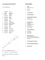
1
Das WALTHER PILOTProgramm
The WALTHER PILOT
Programme
• Hand-Spritzpistolen
• Automatik-Spritzpistolen
• Niederdruck-Spritzpistolen
(System HVLP)
• ZweikomponentenSpritzpistolen
• Pulverbeschichtungs-Systeme
• Materialdruckbehälter
• Drucklose Behälter
• Rührwerk-Systeme
• Airless-Geräte und
Flüssigkeitspumpen
• Materialumlaufsysteme
• Kombinierte Spritz- und
Trockenboxen
• Absaugsysteme mit
Trockenabscheidung
• Absaugsysteme mit
Naßabscheidung
• Pulversprühstände
• Trockner
• Zuluft-Systeme
• Atemschutzsysteme und
Zubehör
• Hand-Held Spray Guns
• Automatic Spray Guns
• Low Pressure Spray Guns
(System HVLP)
• Two-Component Spray Guns
• Material Pressure Tanks
• Nonpressurized Tanks
• Agitator Systems
• Airless Equipment and Transfer
Pumps
• Material Circulation Systems
• Combined Spraying and Drying
Booths
• Dry Back Overspray Extraction
Systems
• Wet Back Overspray Extraction
Systems
• Powder Spray Stands
• Dryers
• Ventilation Systems
• Protective Respiratory Systems
and Accessory Items
WALTHER Spritz- und Lackiersysteme GmbH
Kärntner Str. 18-30 • D-42327 Wuppertal
Tel.: 0202 / 787-0 • Fax: 0202 / 787-217
http://www.walther-pilot.de
E-mail: [email protected]
WA LTH ER PI LOT
Betriebsanleitung / Operating Instructions
Airless-Automatik-Spritzpistole /
Airless-Automatic-Spray Gun
PILOT WA 20
EG-Konformitätserklärung
Declaration of CE-Conformity
Wir, der Gerätehersteller, erklären in alleiniger Verantwortung, daß das Produkt in der
untenstehenden Beschreibung den einschlägigen grundlegenden Sicherheits- und
Gesundheitsanforderungen entspricht. Bei einer nicht mit uns abgestimmten Änderung an dem Gerät oder bei einer unsachgemäßen Verwendung verliert diese
Erklärung ihre Gültigkeit.
Hersteller
WALTHER Spritz-und Lackiersysteme GmbH
Kärntner Str. 18-30
D-42327 Wuppertal
Tel.: 0202 / 787-0
Fax: 0202 / 787-217
www.walther-pilot.de • Email: [email protected]
Typenbezeichnung
Airless - Automatik Spritzpistole
PILOT WA 20
V 20 950
We,the manufacturers of the equipment, hereby declare under our sole responsibility
that the product(s) described below conform to the essential safety requirements.
This declaration will be rendered invalid if any changes are made to the equipment
without prior consultation with us.
Verwendungszweck
Verarbeitung spritzbarer Materialien
Angewandte Normen und Richtlinien
EG-Maschinenrichtlinien 98 / 37 EG
94 / 9 EG (ATEX Richtlinien)
DIN EN 292 Teil 1
DIN EN 292 Teil 2
DIN EN 1953
Gerätebezeichnung
II 2 G c T 5
Type Designation
WALTHER Spritz-und Lackiersysteme GmbH
Kärntner Str. 18-30
D-42327 Wuppertal
Tel.: 0202 / 787-0
Fax: 0202 / 787-217
www.walther-pilot.de • Email: [email protected]
Airless - Automatic Spray Gun
PILOT WA 20
V 20 950
Intended purpose
Processing of sprayable media
Applied Standards and Directives
EU-Machinery Directive 98 / 37 CE
94 / 9 EC (ATEX Directives)
DIN EN 292 Part 1
DIN EN 292 Part 2
DIN EN 1953
Specification according 94 / 9 / CE
Spezifikation im Sinne der Richtlinie 94 / 9 / EG
Kategorie 2
Manufacturer
Tech.File,Ref.:
2405
besondere Hinweise :
Das Produkt ist zum Einbau in ein anderes Gerät bestimmt. Die Inbetriebnahme ist so
lange untersagt, bis die Konformität des Endproduktes mit der Richtlinie 98 / 37 / EG
festgestellt ist.
Category 2
Part marking
II 2 G c T 5
Tech.File,Ref.:
2405
special remarks :
The named product is intended for installation in other equipment.Commissioning is prohibited until such time as the end product has been proved to conform to the provision of
the Directives 98 / 37 / CE.
Wuppertal,den 7. Juli 2003
Wuppertal, the 7th of July 2003
i.V.
i.V.
Name: Torsten Bröker
Stellung im Betrieb: Leiter der Konstruktion und Entwicklung
Name: Torsten Bröker
Position: Manager, Design and Development
Diese Erklärung ist keine Zusicherung von Eigenschaften im Sinne der Produkthaftung. Die Sicherheitshinweise der
Produktdokumentation sind zu beachten.
This Declaration does not give assurance of properties in the sense of product liability.The safety instructions provided in the product documentation must be observed at all times.
Ersatzteilliste PILOT WA 20
Inhaltsverzeichnis
Art.-Nr. V 20 950 00 003 (120 bar)
1
2
3
4
5
6
7
8
9
10
11
12
13
14
15
16
17
18
V 20 900 05
G 16 3XXX
G 16 286 3
V 20 950 15
V 09 103 33
V 09 002 49
V 20 950 01
V 09 103 56
V 09 220 25
V 20 950 10
V 20 950 50
V 09 102 20
V 20 950 02
V 20 950 03
V 66 101 53
V 20 950 20
V 20 950 30
001
003
001
000
003
001
000
203
003
001
003
003
317
003
000
V 20 950 20 103
Überwurfmutter
Materialdüse
Düsendichtung
Nadelsitz komplett
O-Ring
Nadeldichtung
Vorderteil
O-Ring
Nutring
Materialnadel
Kolbenfeder
O-Ring
Hinterteil
Senkschraube
Steuerluftanschluss
Materialanschluss
Matreialdichtung
1
Allgemeines
1.1
1.2
1.3
Kennzeichnung des Modells
Bestimmungsgemäße Verwendung
Sachwidrige Verwendung
2
Technische Beschreibung
3
Allgemeine Sicherheitshinweise
4
Versorgungsleitungen
4.1
4.2
Spritzpistole befestigen
Versorgungsleitungen anschließen
5
Bedienung
5.1
5.2
5.3
5.4
5.5
Sicherheitshinweise
Inbetrieb- und Außerbetriebsetzen
Spritzbildprobe erzeugen
Spritzbild verändern
Spritzpistole umrüsten
6
Reinigung und Wartung
6.1
6.2
6.3
Sicherheitshinweise
Grundreinigung
Routinereinigung
7
Instandsetzung
7.1
7.2
Undichte Nadelpackung austauschen
Materialdüse, und -nadel austauschen
8
Fehlersuche und -beseitigung
9
Entsorgung
10
Technische Daten
Materialanschluss(Umlauf)
Wir empfehlen, alle fettgedruckten Teile (Verschleißteile) auf Lager zu halten.
1
1
1.1
Allgemeines
Kennzeichnung des Modells
Modell:
Airless - Automatik Spritzpistole PILOT WA 20
Typ:
V 20 950
Hersteller:
WALTHER Spritz-und Lackiersysteme GmbH
Kärntner Str. 18-30
D-42327 Wuppertal
Tel.: 0202 / 787-0
Fax: 0202 / 787-217 • www.walther-pilot.de
1.2
Bestimmungsgemäße Verwendung
Die Airless - Automatik Spritzpistole PILOT WA 20 dient ausschließlich der
Verarbeitung spritzbarer Medien. Sämtliche Airless-spritzbaren Medien können verarbeitet werden, wie z.B.:
• Lacke und Farben
• Fette, Öle und Korrosionsschutzmittel
• Kleber
• Keramikglasuren
• Beizen
Sind die Materialien, die Sie verspritzen wollen, hier nicht aufgeführt, wenden Sie
sich bitte an WALTHER Spritz- und Lackiersysteme GmbH, Wuppertal.
Die spritzbaren Materialien dürfen lediglich auf Werkstücke bzw. Gegenstände aufgetragen werden.
Die Temperatur des Spritzmaterials darf 80°C grundsätzlich nicht überschreiten.
Die bestimmungsgemäße Verwendung schließt auch ein, daß alle Hinweise und
Angaben der vorliegenden Betriebsanleitung gelesen, verstanden und beachtet werden.
Das Gerät erfüllt die Explosionsschutz-Forderungen der Richtlinie 94 / 9 EG (ATEX
100a) für die auf dem Typenschild angegebene Explosionsgruppe, Gerätekategorie,
und Temperaturklasse.
Beim Betreiben des Gerätes sind die Vorgaben dieser Betriebsanleitung unbedingt
einzuhalten.
Die vorgeschriebenen Inspektions- und Wartungsintervalle sind einzuhalten.
Die Angaben auf den Geräteschildern bzw. die Angaben in dem Kapitel technische
Daten sind unbedingt einzuhalten und dürfen nicht überschritten werden. Eine Überlastung des Gerätes muss ausgeschlossen sein.
Das Gerät darf in explosionsgefährdeten Bereichen nur nach Maßgabe der zuständigen Aufsichtsbehörde eingesetzt werden.
Der zuständigen Aufsichtsbehörde bzw. dem Betreiber obliegt die Festlegung
der Explosionsgefährdung (Zoneneinteilung).
2
Es ist betreiberseitig zu prüfen und sicherzustellen, daß alle technischen Daten
und die Kennzeichnung gemäß ATEX mit den notwendigen Vorgaben übereinstimmen.
Anwendungen, bei denen der Ausfall des Gerätes zu einer Personengefährdung
führen könnten, sind betreiberseitig entsprechende Sicherheitsmaßnahmen vorzusehen.
Falls im Betrieb Auffälligkeiten erkannt werden, muss das Gerät sofort stillgesetzt
werden und es ist mit WALTHER-PILOT Rücksprache zu halten.
Erdung / Potentialausgleich
Es muß sichergestellt werden, dass die Spritzpistole separat oder in Verbindung
mit dem Gerät auf dem sie aufgebaut ist, ausreichend geerdet ist (maximaler
Widerstand 106Ω).
1.3
Sachwidrige Verwendung
Die Spritzpistole darf nicht anders verwendet werden, als es im Abschnitt 1.2
Bestimmungsgemäße Verwendung geschrieben steht. Jede andere Verwendung
ist sachwidrig. Zur sachwidrigen Verwendung gehören z.B.:
• das Verspritzen von Materialien auf Personen und Tiere
• das Verspritzen von flüssigem Stickstoff.
2
Technische Beschreibung
Bei der WALTHER PILOT WA 20 handelt es sich um eine pneumatisch steuerbare
Airless-Automatik-Spritzpistole in äußerst kleiner Bauweise. Der max. Betriebsdruck beträgt 120 bar.
Der Pistolenkörper aus Edelstahl ist innen und außen oberflächenveredelt. Das zu
verarbeitende Medium wird der Spritzpistole über eine Kolben- bzw. Membranpumpe unter Druck zugeführt. Beim Austritt aus der Materialdüse wird das Medium zerstäubt.
Das Modell PILOT WA 20 wird über ein 3/2-Wege-Magnetventil angesteuert. Wird
das 3/2-Wege-Steuerventils betätigt, tritt die für die Steuerung erforderliche Druckluft in den Zylinderraum der Spritzpistole ein und öffnet die Materialzufuhr.
Wird die Steuerluft durch das 3/2-Wege-Steuerventil wieder unterbrochen, entweicht zunächst die im Zylinder befindliche Druckluft. Der Federdruck der Kolbenfeder drückt anschließend die Materialnadel in ihre Ausgangsstellung zurück und
verschließt die Materialzufuhr.
Der Steuerluftdruck beträgt mindestens 5 bar. Der Spritzautomat ist standardmäßig
für den Anschluß an Umlaufanlagen ausgerüstet. Eine der Bohrungen ist jedoch
mit einem Stopfen verschlossen. Nach der Entfernung dieses Stopfens kann ein
Materialanschluss Pos.17 eingeschraubt werden. Die Pistole ist jetzt für Umlaufbetrieb einsetzbar.
Es können alle handelsüblichen Airless-Düsen verwendet werden.
3
3
Allgemeine Sicherheitshinweise
4
Versorgungsleitungen
Die einschlägigen Unfallverhütungsvorschriften sowie die sonstigen anerkannten
sicherheitstechnischen und arbeitsmedizinischen Regeln sind einzuhalten.
Achtung
Material- und Luftschläuche, die mit einer Schlauchtülle befestigt werden, müssen
zusätzlich mit einer Schlauchschelle gesichert sein.
Benutzen Sie die Spritzpistole nur in gut belüfteten Räumen. Im Arbeitsbereich ist
Feuer, offenes Licht und Rauchen verboten. Beim Verspritzen leichtentzündlicher
Materialien (z. B. Lacke, Kleber, Reinigungsmittel usw.) besteht erhöhte Gesund-heits-,
Explosions- und Brandgefahr.
Achtung
Achten Sie darauf, daß die Anschlüsse für die Materialzufuhr und die Zerstäuberluft nicht vertauscht werden.
Es muß sichergestellt werden, dass die Spritzpistole separat oder in Verbindung mit
dem Gerät auf dem sie aufgebaut ist, ausreichend geerdet ist (max. Widerstand 106W).
Schalten Sie vor jeder Umrüstung, Reinigung oder Instandsetzung die Luft- und
Materialzufuhr zur Spritzpistole drucklos. Der extrem hohe Druck am Pistolen- bzw.
Pumpenauslaß kann schwere Verletzungen verursachen.
4.1
Spritzpistole befestigen
Befestigen Sie die Spritzpistole an einer geeigneten, standsicheren Halterung mit
2 Schrauben M5.
Materialanschluss Pos.16
Halten Sie beim Verspritzen von Materialien keine Hände oder andere Körperteile vor
die unter Druck stehende Düse der Spritzpistole - der extrem hohe Spritzdruck kann
schwere Verletzungen verursachen.
Verwenden Sie Membran- bzw. Kolbenpumpen nur in Zusammenhang mit einem
Materialregler, damit der maximal zulässige Betriebsüberdruck von 120 bar nicht überschritten werden kann.
Anschluss
für Umlaufbetrieb
Gewindebohrungen
zum Befestigen
Steuerluftanschluss
Pos.15
Richten Sie die Spritzpistole nicht auf Personen und Tiere - Verletzungsgefahr.
4.2
Beachten Sie die Verarbeitungs- und Sicherheitshinweise der Hersteller von Spritzmaterial und Reinigungsmittel. Insbesondere aggressive und ätzende Materialien können gesundheitliche Schäden verursachen.
Die partikelführende Abluft ist vom Arbeitsbereich und Betriebspersonal fernzuhalten.
Tragen Sie dennoch vorschriftsgemäßen Atemschutz und vorschriftsgemäße Arbeitskleidung, wenn Sie mit der Spritzpistole Materialien verarbeiten. Umherschwebende
Partikel gefährden Ihre Gesundheit.
Tragen Sie im Arbeitsbereich der Spritzpistole einen Gehörschutz. Der erzeugte
Schallpegel der Spritzpistole beträgt ca. 82 dB (A).
Achten Sie stets darauf, daß nach Montage- und Wartungsarbeiten alle Muttern und
Schrauben fest angezogen sind.
Verwenden Sie nur Original-Ersatzteile, da WALTHER nur für diese eine sichere und
einwandfreie Funktion garantieren kann.
Bei Nachfragen zur gefahrlosen Benutzung der Spritzpistole wenden Sie sich bitte an
WALTHER Spritz- und Lackiersysteme GmbH, D-42327 Wuppertal.
4
Versorgungsleitungen anschließen
Schließen Sie den geerdeten Materialschlauch am Materialregler und am Materialanschluss Pos.16 der Spritzpistole an. Achtung: Verwenden Sie die Pumpe nur in
Zusammenhang mit einem Materialregler, damit der maximal zulässige Betriebsüberdruck von 120 bar nicht überschritten werden kann.
Umlaufbetrieb:
Schrauben Sie die Verschlußschraube aus dem Pistolenkörper aus. Schrauben
Sie an dieser Stelle einen Materialanschluss Pos.18 ein. Achten Sie auf feste Verschraubung.
Materialanschluß:
Befestigen Sie die Versorgungsleitung am Anschluß Pos.16 der Spritzpistole.
Achten Sie auf feste Verschraubung.Sollte der Materilanschluss öfter demontiert
werden,müssen Sie die Materialdichtung Pos.17 austauschen,um eine optimale
Dichtigkeit zu erreichen.
Steuerluftanschluß:
Befestigen Sie die Versorgungsleitung der Steuerluft an dem Magnetvenil und der
Schnellverschraubung Pos. 15. Achten Sie auf feste Verschraubung.
Die Pistole ist nun betriebsbereit.
5
5
5.1
Bedienung
Sicherheitshinweise
Beachten Sie bei der Bedienung der Spritzpistole insbesondere die nachfolgenden
Sicherheitshinweise!
• Bei jeder Arbeitsunterbrechung muß die Spritzanlage drucklos geschaltet werden.
• Tragen Sie vorschriftsmäßigen Atemschutz und Arbeitskleidung, wenn Sie mit der
Spritzpistole Materialien verspritzen. Umherschwebende Partikel gefährden Ihre
Gesundheit.
• Tragen Sie im Arbeitsbereich der Spritzpistole einen Gehörschutz. Der erzeugte
Schallpegel der Spritzpistole beträgt ca. 82 dB (A).
• Im Arbeitsbereich ist Feuer, offenes Licht und Rauchen verboten. Beim Verspritzen
leicht entzündlicher Materialien (z. B. Lacke, Kleber) besteht erhöhte Explosionsund Brandgefahr.
5.2
Inbetrieb- und Außerbetriebsetzen
Vor der ersten Inbetriebnahme den Spritzautomat mit dem zum verspritzten Medium
passenden Lösemittel durchspülen.
Warnung
Schalten Sie vor jeder Umrüstung die Spritzanlage drucklos - Verletzungsgefahr.
Bevor Sie die Spritzpistole in Betrieb setzen können, muß der Materialdruck an der
Spritzpistole anstehen.
Achtung
Der Materialdruck darf nicht höher eingestellt sein als:
- 120 bar ( Art.-Nr. V 2095000003)
Der Steuerluftdruck darf 8 bar nicht überschreiten, da sonst kein funktionssicherer
Betrieb der Spritzpistole gewährleistet ist.
Warnung
Die gesamte Spritzanlage muß nach Arbeitsende immer drucklos geschaltet werden.
Die unter Druck stehenden Leitungen können platzen und nahestehende Personen
durch das ausströmende Material verletzen.
5.3
Warnung
Halten Sie beim Verspritzen von Materialien keine Hände oder andere Körperteile
vor die unter Druck stehende Düse der Spritzpistole - der extrem hohe
Spritzdruck kann schwere Verletzungen verursachen.
Warnung
Achten Sie beim Inbetriebsetzen der Spritzpistole darauf, daß sich keine Person
im Spritzbereich befindet - Verletzungsgefahr.
1. Setzen Sie die Spritzpistole in Betrieb, um eine Spritzbildprobe zu erzeugen
(siehe 5.2 Inbetrieb- und Außerbetriebsetzen).
2. Kontrollieren Sie die Spritzbildprobe und verändern Sie ggf. die Einstellungen
an der Spritzpistole (siehe 5.4 Spritzbild verändern).
5.4
Spritzbild verändern
Sie können an der PILOT WA 20 durch die folgenden Einstellungen das Spritzbild
verändern.
Materialdurchflußmenge einstellen
Die Einstellung der Materialdurchflußmenge - und somit der Spritzstrahlbreite - ist
zunächst anhand der Auswahl einer geeigneten Düsengröße vorzunehmen.
Durch die Einstellung des Materialdruckes am Materialregler kann darüberhinaus
die Durchflußmenge beeinflußt werden.
Materialdruck regulieren
Den geeigneten Materialdruck stellen Sie an der Pumpe und am Materialdruckregler ein. Beachten Sie dabei die Anweisungen und Sicherheitshinweise des
Herstellers.
Wenn Sie das Spritzbild über die bereits erwähnten Möglichkeiten hinaus verändern wollen, muß die Spritzpistole umgerüstet werden
(siehe 5.5 Spritzpistole umrüsten)
Spritzbildprobe erzeugen
Eine Spritzbildprobe sollte immer dann erzeugt werden, wenn:
• die Spritzpistole zum erstenmal in Betrieb gesetzt wird
• das Spritzmaterial ausgetauscht wird
• die Pistole zur Wartung oder Instandsetzung zerlegt wurde.
Das Spritzbild kann auf ein Probewerkstück, Blech, Pappe oder Papier abgegeben
werden.
6
7
5.5
Spritzpistole umrüsten
6.2
Grundreinigung
Warnung
Schalten Sie vor jeder Umrüstung die Spritzanlage drucklos - Verletzungsgefahr.
Damit die Lebensdauer und die Funktion der Spritzpistole lange erhalten bleibt,
muß die Spritzpistole regelmäßig gereinigt und geschmiert werden.
Warnung
Unterbrechen Sie vor jeder Umrüstung die Luft- und Materialzufuhr zur Spritzpistole Verletzungsgefahr.
Achtung
Legen Sie die Spritzpistole nie in Lösemittel oder ein anderes Reinigungsmittel.
Die einwandfreie Funktion der Spritzpistole kann sonst nicht garantiert werden.
Hinweis
Zur Durchführung der im Folgenden aufgeführten Arbeitsschritte benutzen Sie bitte
die Zeichnung am Anfang dieser Betriebsanleitung.
Achtung
Verwenden Sie zur Reinigung keine harten oder spitzen Gegenstände. Präzisionsteile der Spritzpistole könnten sonst beschädigt werden und das Spritzergebnis
verschlechtern.
Materialdüse wechseln
1. Entfernen Sie die Überwurfmutter Pos. 1 (SW 22)
2. Nehmen Sie die Materialdüse Pos. 2 und die Dichtung Pos. 3 vom Pistolenkörper.
Die Montage erfolgt in umgekehrter Reihenfolge.
Materialfilter wechseln
Zur angemessenen Filterung des Materials können Sie grob- und feinmaschige Filter
verwenden.
1. Schalten Sie das komplette Spritzsystem drucklos.
2. Entfernen Sie den Materialschlauch / die Materialschläuche.
3. Entfernen Sie den Materialfilter.
Die Montage erfolgt in umgekehrter Reihenfolge.
6
6.1
Reinigung und Wartung
Sicherheitshinweise
• Schalten Sie vor jeder Wartung die Spritzanlage drucklos - Verletzungsgefahr.
• Unterbrechen Sie vor jeder Wartung die Luft- und Materialzufuhr zur Spritzpistole.
• Im Arbeitsbereich ist Feuer, offenes Licht und Rauchen verboten. Beim Verspritzen
leichtentzündlicher Materialien (z. B. Reinigungsmittel) besteht erhöhte Explosionsund Brandgefahr.
• Beachten Sie die Sicherheitshinweise des Reinigungsmittel-Herstellers. Insbesondere aggressive und ätzende Reinigungsmittel können gesundheitliche Schäden
verursachen.
8
Verwenden Sie zur Reinigung der Spritzpistole nur Reinigungsmittel, die vom
Hersteller des Spritzmaterials angegeben werden und die folgenden Bestandteile
nicht enthalten:
• halogenierte Kohlenwasserstoffe
(z. B. 1,1,1, Trichloräthan, Methylen-Chlorid usw.)
• Säuren und säurehaltige Reinigungsmittel
• regenerierte Lösemittel (sog. Reinigungsverdünnungen)
• Entlackungsmittel.
Die o.g. Bestandteile verursachen an galvanisierten Bauteilen chemische
Reaktionen und führen zu Korrosionsschäden.
Für Schäden, die aus einer derartigen Behandlung herrühren, übernimmt
WALTHER PILOT keine Gewährleistung.
Reinigen Sie die Spritzpistole
• vor jedem Farb- bzw. Materialwechsel
• mindestens einmal wöchentlich
• materialabhängig und je nach Verschmutzungsgrad mehrfach wöchentlich.
Sie erhalten so die sichere Funktion der Spritzpistole.
1. Zerlegen Sie die Pistole gemäß 5.5 Spritzpistole umrüsten.
2. Reinigen Sie die Materialdüse mit einem Pinsel und dem Reinigungsmittel.
3. Reinigen Sie alle übrigen Bauteile und den Pistolenkörper mit einem Tuch
und dem Reinigungsmittel.
4. Bestreichen Sie folgende Teile mit einem dünnen Fettfilm:
• Materialnadel
• Druckfeder
• alle gleitenden Teile und Lagerstellen
• Die beweglichen Innenteile sind wenigstens einmal wöchentlich zu fetten.
• Die Federn sollten ständig mit einem leichten Fettüberzug versehen sein.
Verwenden Sie dazu ein säurefreies, nicht harzendes Fett und einen Pinsel.
Anschließend wird die Spritzpistole in umgekehrter Reihenfolge zusammengesetzt.
9
6.3
Routinereinigung
Bei Farbwechseln oder nach Arbeitsende können Sie die Spritzpistole auch reinigen,
ohne diese dabei zerlegen zu müssen.
Hinweis
Die aus der Pistole entnommenen Gebrauchteile dürfen nicht wieder verwendet
werden, da sonst eine funktionssichere Dichtwirkung nicht gewährleistet ist.
7.2
Bevor Sie die Routingereinigung durchführen, muß folgende Voraussetzung erfüllt
sein:
• Achten Sie darauf, daß das verwendete Reinigungsmittel zu dem zu verarbeitenden
Material paßt.
Führen Sie die folgenden Arbeitsschritte durch:
1. Setzen Sie die Spritzpistole in Betrieb, (siehe 5.2 Inbetriebsetzen).
2. Spülen Sie die Pistole mit möglichst geringem Druck.
3. Setzen Sie die Spritzpistole erst außer Betrieb, wenn diese nur noch klares
Reinigungsmittel verspritzt.
Die gesamte Spritzanlage sollte nun bis zum nächsten Einsatz drucklos geschaltet
werden.
7
Instandsetzung
Warnung
Schalten Sie vor jeder Instandsetzung die gesamte Spritzanlage drucklos Verletzungsgefahr.
Warnung
Unterbrechen Sie vor jeder Instandsetzung die Luft- und Materialzufuhr zur Spritzpistole - Verletzungsgefahr.
Hinweis
Zur Durchführung der im Folgenden aufgeführten Arbeitsschritte benutzen Sie bitte
die Zeichnung am Anfang dieser Betriebsanleitung.
7.1
Materialnadel austauschen
Zerlegen Sie die Spritzpistole gemäß Abschnitt 5.5 Spritzpistole umrüsten
1. Schrauben Sie die Nadelsitz Pos. 4 ab.
2. Entfernen Sie den Materialanschluss Pos. 16 samt Materialdichtung Pos. 17
und das Hinterteil Pos. 13 durch Lösen der 2 Senkkopfschrauben Pos. 14.
3. Schieben Sie die Materialnadel Pos. 10 nach hinten aus dem Vorderteil
Pos. 7 heraus.
Die Montage erfolgt in umgekehrter Reihenfolge.
Materialfilter austauschen
Wechseln Sie den Materialfilter gemäß 5.5 Spritzpistole umrüsten.
Hinweis
Alle beweglichen und gleitenden Bauteile müssen vor dem Einbau in den
Pistolen- körper mit einem säurefreien, nicht harzenden Fett eingefettet werden.
Reparaturset:
WALTHER PILOT hält für die Airless-Automatik-Spritzpistole PILOT WA 20 einen
Reparaturset bereit, der sämtliche Verschleißteile enthält.
Art. Nr.: V 16 130 000 10
Bestehend aus: Materialdüse Pos. 2, Düsendichtung Pos. 3, Nadelsitz kompl.
Pos. 4, O-Ring Pos. 5, Nadeldichtung Pos. 6,O-Ring Pos.8, Nutring Pos. 9,
Materialnadel kompl. Pos. 10, Kolbenfeder Pos. 11, O-Ring Pos.12,
Materialdichtung Pos. 17.
Undichte Nadeldichtung austauschen
1. Schrauben Sie die Überwurfmutter Pos.1 ab.
2. Schrauben Sie den Nadelsitz Pos. 4 ab.
3. Entfernen Sie den Materialanschluss Pos. 16 samt Materialdichtung Pos. 17
und das Hinterteil Pos. 13 durch Lösen der 2 Senkkopfschrauben Pos. 14.
4. Schieben Sie die Materialnadel Pos.10 nach hinten aus dem Vorderteil Pos. 7
heraus.
5. Ziehen Sie den Nutring Pos. 9 nach hinten heraus. Verwenden Sie dazu einen
festen Draht, dessen Ende zu einem kleinen Haken umgebogen ist.
6. Ziehen Sie die Nadeldichtung Pos. 6 mit den kleinen Haken nach vorne heraus.
7. Ersetzen Sie Nadeldichtung, Nutring und Materialdichtung durch Neuteile.
Die Montage der restlichen Bauteile erfolgt in umgekehrter Reihenfolge.
10
11
8
Fehlersuche und -beseitigung
Warnung
Schalten Sie vor jeder Instandsetzung die Steuer- und Zerstäuberluft sowie die
Materialzufuhr zur Spritzpistole drucklos - Verletzungsgefahr.
Fehler
Düse ist undicht
zu wenig Material
Spritzstrahl wird
nicht mehr breit
Material tritt aus der
Leckagebohrung
9
-
Ursache
Nadeldichtung Pos. 6
Nadelsitz Pos. 4
O-Ring Pos. 5
Filter verschmutzt
Abhilfe
• Überprüfen
• Reinigen, ggf. austauschen
• Reinigen
- Düse zu klein
• Größere Düse wählen
- Materialdruck zu niedrig
• Materialdruck erhöhen
- Düse verschlissen
• Auswechseln
- Nadeldichtung Pos. 6
• Auswechseln
Entsorgung
Die Spritzmedien sowie die bei der Reinigung und Wartung anfallenden Materialien
sind den Gesetzen und Vorschriften entsprechend sach- und fachgerecht zu entsorgen.
Warnung
Beachten Sie die Hinweise des Herstellers der Spritz- und Reinigungsmittel.
Unachtsam entsorgtes Material gefährdet die Gesundheit von Mensch und Tier.
10
0.38
Technische Daten
Netto-Gewicht:
158 g
Düsenausstattung nach Wahl:
siehe Tabelle
Druckbereiche
max. Steuerluftdruck
max. Materialdruck
8 bar
120 bar (V 2095000003)
max. Betriebstemperatur:
80°C
Schallpegel
(gemessen in ca. 1 m
Abstand zur Spritzpistole):
Technische Änderungen vorbehalten.
12
Düsen- Bestell- Win- Spritzbild Volumenstrom l/min Düsen- Bestellgröße größe
kel
in
niederhoch- größe größe
mm
viskose/ viskose
Materialien
163107 10°
50-100
163117
0.189
163207 20° 100-150
163217
0.18 163307 30° 150-200
163317
163407 40° 200-250
163417
163517
163109 10°
50-100
0.43
163617
163209 20° 100-150
163717
0.23 163309 30° 150-200
0.303
163817
163409 40° 200-250
163917
163509 50° 250-300
163609 60° 300-350
163119
163219
163111 10°
50-100
163319
163211 20° 100-150
163419
0.454
163311 30° 150-200
0.28 163411 40° 200-250
0.48 163519
163619
163511 50° 250-300
163719
163611 60° 300-350
163819
163711 70° 350-400
163919
163113 10°
50-100
163121
163213 20° 100-150
163221
163313 30° 150-200
163321
0.643
163413 40° 200-250
0.33 163513 50° 250-300
163421
163521
163613 60° 300-350
0.53
163621
163713 70° 350-400
163721
163813 80° 400-450
163821
163115 10°
50-100
163921
163215 20° 100-150
82 dB (A)
0.58
0.63
0.68
163315
163415
163515
163615
163715
163815
30°
40°
50°
60°
70°
80°
150-200
200-250
250-300
300-350
350-400
400-450
163723
163823
163923
163125
163225
163325
163425
163525
163625
163725
163825
163925
163127
163227
163327
163427
163527
163627
163727
163827
163927
70°
80°
90°
10°
20°
30°
40°
50°
60°
70°
80°
90°
10°
20°
30°
40°
50°
60°
70°
80°
90°
350-400
400-450
450-500
50-100
100-150
150-200
200-250
250-300
300-350
350-400
400-450
450-500
50-100
100-150
150-200
200-250
250-300
300-350
350-400
400-450
450-500
0.871
0.58
2.082
0.74
2.498
2.914
0.79
Win- Spritzbild Vol.strom l/min
kel
in
nieder- hochmm
viskose/ viskose
Materialien
10°
20°
30°
40°
50°
60°
70°
80°
90°
50-100
100-150
150-200
200-250
250-300
300-350
350-400
400-450
450-500
10°
20°
30°
40°
50°
60°
70°
80°
90°
50-100
100-150
150-200
200-250
250-300
300-350
350-400
400-450
450-500
10°
20°
30°
40°
50°
60°
70°
80°
90°
50-100
100-150
150-200
200-250
250-300
300-350
350-400
400-450
450-500
163123
163223
163323
163423
163523
163623
10°
20°
30°
40°
50°
60°
50-100
100-150
150-200
200-250
250-300
300-350
163129
163229
163329
163429
163529
163629
163729
163829
163929
10°
20°
30°
40°
50°
60°
70°
80°
90°
50-100
100-150
150-200
200-250
250-300
300-350
350-400
400-450
450-500
163131
163231
163331
163431
163531
163631
163731
163831
163931
10°
20°
30°
40°
50°
60°
70°
80°
90°
50-100
100-150
150-200
200-250
250-300
300-350
350-400
400-450
450-500
1.136
1.363
1.741
2.082
3.331
0.871
3.861
1.098
13
Listing of Replacement Parts PILOT WA 20
Art.No. V 20 950 00 003 (120 bar)
1
2
3
4
5
6
7
8
9
10
11
12
13
14
15
16
17
V 20 900 05
G 16 3XXX
G 16 286 3
V 20 950 15
V 09 103 33
V 09 002 49
V 20 950 01
V 09 103 56
V 09 220 25
V 20 950 10
V 20 950 50
V 09 102 20
V 20 950 02
V 20 950 03
V 66 101 53
V 20 950 20
V 20 950 30
001
003
001
000
003
001
000
203
003
001
003
003
317
003
000
Sleeve Nut
Material Nozzle
Nozzle Seal
Needle Seat
O-Ring
Needle Seal
Forepart
O-Ring
“V”-Package Ring
Material Control Needle
Piston Spring
O-Ring
Rearpart
Countersunk Srew
Control Air Connection
Material Connection
Material seal
Listing of Contents
1
General
1.1
1.2
1.3
Identification of Model Version
Normal Use
Improper Use
2
Technical Description
3
General Safety Warnings
4
Assembly / Installation / Supply Lines
4.1
4.2
Mounting of Spray Gun
Connection of Input Lines
5
Operational Handling
5.1
5.2
5.3
5.4
5.5
Safety Warnings
Starting/Stopping Requirements
Spray Pattern Test
Spray Pattern Adjustments
Retooling of Spray Gun
6
Servicing and Maintenance
6.1
6.2
6.3
Safety Warnings
Cleaning - Complete
Cleaning - Routine
7
Repairs / Replacements
7.1
7.2
Replacement of defective Needle Seal Packings
Replacement of Spray Tips, Material Control Needles and
Material Filter
8
Troubleshooting and Corrective Action
9
Disposal of Cleaning/Servicing Substances
10
Specification Data
Variants for Art.-No. V2095000003(Material Circulation Mode)
18
V 20 950 20 103
Material Connection (Circulation Mode)
We recommend that the bold-faced replacement parts (i.e.wearing parts) are
held on stock !
1
1
1.1
General
Identification of Model Version
Model:
Airless - Automatic Spray Gun PILOT WA 20
Type:
V 20 950
Manufacturer:
WALTHER Spritz- und Lackiersysteme GmbH
Kärntner Strasse 18-30
D-42327 Wuppertal - Germany
TEL: 0202/787-0
FAX: 0202/787-217 • www.walther-pilot.de
1.2
The operator must check and ensure that all technical data and the marking of
the equipment in accordance with ATEX are compliant with the necessary requirements.
Normal Use
The airless - automatic spray gun model PILOT WA 20 is exclusively designed for
use with all airless-sprayable material types and grades such as, for example:
• paints and lacquers
• greases, oils and corrosion preventives
• adhesive compounds
• ceramic glazes
• pickling solutions
If your specific material is not listed above, please contact us for further and detailed
information.
Please note that sprayable material may only be applied to workpieces and/or similar
items.
The temperature of the spraying material shall never exceed 80° C.
The term "normal use" also implies that any and all safety warnings, operational
handling details, etc., as contained in these Operating Instructions, are carefully read,
understood and duly complied with.
This equipment complies with the explosion protection requirements of Directive
94/9/EC (ATEX 100a) for the explosion group, equipment category and temperature
class indicated on the type plate. When using the equipment, the requirements specified in these Operating Instructions must be observed at all times.
The technical data indicated on the equipment rating plates and the specifications in
the chapter "Technical Data" must be complied with at all times and must not be
exceeded. An overloading of the equipment must be ruled out.
The equipment may be used in potentially explosive atmospheres only with the authorisation of the relevant supervisory authority.
The relevant supervisory authority or the operator of the equipment are responsible for determining the explosion hazard (zone classification).
The operator must provide corresponding safety measures for all applications in
which the breakdown of the equipment might lead to danger to persons.
If any irregularities are observed while the equipment is in operation, the equipment must be put out of operation immediately and WALTHER PILOT must be
consulted.
Grounding / Equipotential Bonding
You must ensure that the spray gun is properly earthed (grounded) either separately or in connection with the equipment with which it is being used (maximum
resistance 106 Ω).
1.3
Improper Use
This spray gun shall not be used for purposes other than set forth in the above
Chapter "Normal Use". Any other form of use and/or application is prohibited and
considered as improper use in contrast to the original engineering design concept. The term "improper use" also includes such operations as may be:
• spraying of material onto persons and animals
• spraying of liquid nitrogen, etc.
2
Technical Description
The WALTHER PILOT WA 20 is a pneumatic-controlled airless - automatic spray
gun of extreme mini-sized design. Its maximum operating pressure rates 120 bar.
The gun body is made of stainless steel with hard-coated surfaces inside and outside. The spraying medium is fed to the gun in pressurized condition by a piston
oder diaphragm pump and atomized the moment it exits from the noozle.
The PILOT WA 20 spray gun is controlled across a 3/2-way solenoid valve which,
upon actuation, directs control air into the cylinder inside the gun body so as to
open - in sequence - the material input.
Closing of the 3/2-way valve is followed by the control air escaping from the cylinder inside the gun body, upon which the spring-loaded material control needle
returns to its initial position, where it shuts the material input off.
The control air pressure must rate at least 5 bar. This automatic spray gun is basically designed for operation in circulation systems, with one of the bores sealed
with a screw plug which, once removed, can be replaced with a material connection (Item 17). The gun is now ready for connection to a circulation system.
All commercial airless spray noozles can be used in this PILOT WA 20 gun.
2
3
3
General Satety Instruction
4
Assembly / Installation / Supply Lines
All applicable accident prevention rules and regulations as well as other recognisedindustrial safety, health rules and regulations must be observed at all times.
Warning
Material and air hoses attached by way of a hose fitting must be secured by additional hose clips.
Fire, naked flames and smoking are strictly prohibited within the workung area.
WARNING-during the spraying of flammable materials (e.g. lacquers,adhesives,
cleaning agents,etc.),there isan increased risk to health as well as an increased
risk of explosion and fire.Use the spray gun only in well-ventilated rooms.
Warning
Make sure not to confuse the material and atomizing air connections.
You must ensure that the spray gun is properly earthed (grounded) either separately
or in connection with the equipment with which it is being used (maximum resistance
106 Ω).
Install the gun in a suitable and stable mounting device - use two Size M5 screws
to fasten the gun in position.
Material Input
4.1
Mounting of Spray Gun
Connection Item 16
Befor carrying out maintenance or servicing work, always ensure that the air and
material feed to the the spray gun have been depressurised. - Risk of injury!
Keep your hands and other extremities away from the front of the pressurised gun
during the spraying process. - Risk of injury.
Piston or diaphragm pumps must always be operated in combination with a material
flow regulator valve in order to ensure that the allowable maximum operating overpressure of 120 bar is never exceeded.
Input Connection for
Material Connection Mode
Never point the spray gun at person or animals. Risk of injury!
4.2
It is important that all processing specifications and safety warnings issued by the
manufacturers of spraying and cleaning media are duly complied with. Remember:
Aggressive and corrosive media represent risks and hazards to personal health, and
may cause material damage.
Airborne particles represent a health hazard and must therefore be kept away from
the working area, towards which end ventilation systems are used. Extra protection is
still needed and it is therefore important that anybody engaged with spraying media
wears proper respiratory protection masks and protective overalls.
Spray guns produce sound levels of up to about 82 dB (A). It is therefore important to
wear suitable hearing protectors.
It is important to ensure that nuts, screws and fasteners are properly tightened, especially after servicing and repair work.
Make sure you use original WALTHER-PILOT replacement parts designed for functional reliability and efficiency.
If you require further details concerning the safe use of this spray gun, do not hesitate to contact us.
4
Tapped Bored
to Confirm
Control Air
Connection Item 15
Connection of Input Lines
Connect the grounded material hose to the material flow regulator valve and to
the material connection (Item 16) of the gun. WARNING: Make sure that the
transfer pump operates in combination with a material flow regulator valve - this is
important to ensure that the allowable maximum operating overpressure of 120
bar in never exceeded.
Material Circulation Mode:
Remove the screw plug from the gun and replace it with the material connection
(Item 18).Make sure that all connections are properly tightened.
Material Input Connection:
Connect the material input line to the barrel nipple (Item 16) of the gun and make
sure that this connection is properly tightened.
Control Air Connection:
Connect the control air line to the solenoid valve and to the quick- release fitting
(Item 15) of the gun. Make sure that these connections are properly tightened.
The gun is now ready for operation.
5
5
5.1
Operational Handling
Safety Warnings
Make sure the following safety warnings are met to taking this spray gun into
operation.
• Remove all pressures from the gun and the system whenever operations are interrupted.
• Make sure to wear proper respiratory protection masks and protective overalls wheneveryou are operating this spray gun.
• Air-borne particles represent a health hazard.
• Make sure to wear suitable hearing protectors. Spray guns produce sound levels of
up to about 82 dB (A).
• Make sure your working area is absolutely free from open fires and naked lights risk of fire and explosion.
5.2
Starting/Stopping Requirements
When taking the spray gun into operation, flush the gun with a solvent compatible
with the medium last used.
Warning
Make sure that all pressures are removed from the gun and the system before retooling - risk of injury.
Make sure you have the right material pressure at the gun before you start with your
job.
Warning
The material pressure shall never be set to a rating in excess of:
- 120 bar (V 20 950 00 003)
The control air pressure shall not exceed 8 bar as, otherwise, the functional reliability
of the spray gun will suffer.
Warning
The spray gun and the system must always be relieved of all pressures whenever
work is terminated - lines left in pressurized condition could burst, with their contents
likely to injure anybody present nearby.
5.3
Warning
Keep your hands and other extremities away from the front of the pressurised gun
during the spraying process. - the extremely high spraying pressure (120 bar) can
cause severe injuries.
Warning
Make sure that nobody is present in the spraying zone when the gun is started imminent risk of injury.
1. Start the gun to produce a spray pattern sample
(see also 5.2 "Starting / Stopping Requirements).
2. Inspect the sample and readjust the settings of the gun as may be required
(see also 5.4 "Spray Pattern Adjustments").
5.4
Spray Pattern Adjustments
The spray pattern of the PILOT WA 20 gun may be adjusted as follows:
Adjustment of the Material Flow Volume
The flow volume depends on the spray tip size which, in turn, determines the
spray jet width. So it is best to start with selecting the appropriate spray tip size.
The next step would then be an adjustment of the material pressure at the flow
regulator valve.
Adjustment of the Material Pressure
Select the required material pressure by adjusting the pump pressure in combination with the material flow regulator valve. Make sure to comply with the
Operating Instructions and Safety Warnings issued be the manufacturers concerned.
If you wish to change the spraying pattern beyond the adjustments outlined so far,
you should retool the spray gun (see 5.5 "Retooling of Spray Gun").
Spray Pattern Test
Spray pattern tests should be performed whenever:
• the spray gun is taken into operation for the first time
• the spraying medium is changed
• the spray gun was taken apart for servicing or repairs
The spray pattern is best tested using a workpiece sample, a sheet of metal, cardboard or paper.
6
7
5.5
Retooling of Spray Gun
Cleaning - Complete
Warning
Make sure that all pressures are removed from the gun and the system before retooling - risk of injury.
It is recommended practice to clean and lubricate the spray gun at regular intervals as this will greatly help towards ensuring a long service life and functional
reliability.
Warning
Shut the air and material input off before retooling - risk of injury.
Caution
Never immerse the spray gun in solvent or any other cleaning solution as such
measure is highly likely to affect the functional reliability and efficiency of the gun.
Note
See the drawing for detailed information when performing the retooling steps
outlined below.
Replacement of Material Outlet Nozzle (i.e. Airless Spray Tip)
1. Remove the sleeve nut (Item 1) (use a Size 22 mm wrench)
2. Remove the Airless spray tip (Item 2) and seal (Item 3) from the gun body
Installation of another or new Airless spray tip to be in reverse order.
Replacement of Material Filters
Coarse- or fine-grade filters may be used for efficient material filtration.
1. Remove all pressures from the gun and the system.
2. Remove the material hose(s).
3. Remove the material filter.
Installation of new filters to be in reverse order.
6
6.1
Servicing and Maintenance
Safety Warnings
• Remove all pressures from the gun and the system before performing any servicing
and/or maintenance work - imminent risk of injury.
• Shut the air and material input off before retooling - risk of injury.
• No open fires and naked lights as well as smoking are allowed in the work area risk of fire and explosion, particularly when spraying readily flammable media such
as, for example, paints, lacquers, cleaning solutions, etc.
• All processing specifications and safety warnings issued by the manufacturers of
spraying and cleaning media must be duly complied with. Aggressive and corrosive
media represent risks and hazards to personal health.
8
6.2
Caution
Do not use any hard, pointed or sharp-edged objects when cleaning the spray
gun. Any damage of the precision-made parts will certainly affect your spraying
results.
Cleaning of the gun only with cleaning solutions recommended by the manufacturer of the spraying material used at the time. It is important to make sure that
cleaning solutions do not contain any of the following constituents:
• halogenated hydrocarbons
(e.g. 1,1,1-trichloroethane; methylene chloride, etc.)
• acids and acidiferous cleaning solutions
• regenerated solvents (so-called cleaning dilutions)
• paint removers
The above constituents cause chemical reactions with electroplated components
resulting in corrosion damage.
Claims for damage arising from non-compliance with the above requirements will
not be accepted on the part of WALTHER PILOT.
Clean the spray gun
• prior to each change of the spraying medium
• at least once a week
• as often as may be required by the spraying medium handled and the resulted
degree of fouling.
The above cleaning measures are designed to maintain the functional efficiency
of the gun.
1. Dismantle the spray gun (see 5.5 "Retooling of Spray Gun").
2. Use a soft brush together with a compatible cleaning solution to clean the
noozle.
3. Use a suitable cloth with a compatible cleaning solution to clean the gun body
and all remaining parts
4. Apply a thin film of the appropriate grease type/grade to the:
• Material control needle
• piston spring
• all sliding parts and bearing surfaces
• all internal moving parts should be greased at least once a week
• all springs should covered by a thin grease film at all times.
9
Make sure to use a non-acidic, non-resinogenic grease type/grade and apply same
with a soft brush.
Assemble the spray gun in reverse order.
6.3
Cleaning - Routine
7. Change used needle seal, “V”-package ring and the material seal by new parts.
Assembly of the remaining parts to be in reverse order.
Note
Used parts removed from the gun are not to be used again because their sealing
efficiency can no longer be relied upon.
The spray gun need not necessarily be dismantled for cleaning if and when the
spraying medium is changed in regular intervals or upon termination of work (depending, of course, on the material used).
7.2
The following requirements must be met before the routine cleaning work can be performed:
• Make sure that the cleaning solution is compatible with the material to be used.
Dismantle the gun as outlined in 5.5 "Retooling of Spray Gun".
1. Remove the needle seat (Item 4).
2. Take off the marerial connection (Item 16)with the material seal (item 17) and
the rearpart (Item 13) by releasing the 2 countersunk srew (Item 14).
3. Push out the material control needle (Item 10) backewards of the forepart (Item 7).
Now proceed as follows:
1. Take the spray gun into operation (see 5.2 "Starting/Stopping requirements).
2. Flush the spray gun at the lowest possible pressure rating.
3. Do not stop the spray gun until clear cleaning solution emerges from the Airless
spray tip.
All pressures should now be removed from the complete spraying system - which
should be left in this condition until it is taken into operation again.
7
Replacement of Material Control Noozle
Assembly to be in reverse order.
Replacement of Material Filter
Replacement of material filter to be as outlined in 5.5 "Retooling of Spray Gun".
Note
All moving and sliding parts must be lubricated with a non-acidic, non-resinogenic
grease type/grade prior to installation in the gun body.
Repairs / Replacements
Repair Kit:
Warning
Air and material inputs must be shut off prior to re-tooling - risk of injury.
Warning
Prior to any repairs/replacements:Make sure that the spray gun is in unpressurized
condition, i.e. all air and material inputs must be shut off - Risk of injury.
Note
Please refer to the exploded view at the beginning of this manual to perform the
steps detailed below.
7.1
A repair kit, made up of all wearing parts, is available from WALTHER PILOT for
the Automatic Airless Spray Gun Model PILOT WA 20 (120 bar):
Art. No. V 16 130 000 10
consisting of: Material noozle (item 2), Noozle seal (item 3), Needle seat complete
(Item 4), O-Ring (Item 5), Needle seat (Item 6), O-Ring (Item 8), "V"-Packing Ring
(Item 9), Material control needle complete (Item 10), Piston Spring (Item 11),
O-Ring (Item 12), Material seal (item 17).
Replacement of defective Needle Seal
1. Remove the sleeve nut (Item 1).
2. Remove the needle seat (Item 4).
3. Take off the material connection (Item 16) with the material seal (item 17)and the
rearpart (Item 13 )by releasing the 2 countersunk srew (Item 14).
4. Push out the material control needle (Item 10) of the forepart (Item 7).
5. Pull the “V”-package ring (Item 4) off its seat - use a suitable piece of wire,
with a small hook formed at one end, for this purpose.
6. Pull the needle seal (Item 6) with the small hook off its seat.
10
11
8
Troubleshooting and Corrective Action
Warning
Make sure that the control air, atomizing air and material input to the spray gun are
shut off prior to any repair work - risk of injury.
Fehler
Ursache
Abhilfe
Material noozle is
- Needle seal (item 6)
• Check
- Needle seat (item 4)
leaky
- O-Ring (item 5)
• Clean and / or Replace
Insufficient
- Filter clogged
• Clean
Material Input
- Material noozle too small • Change to larger Size
Noozle
size
0.18
0.23
- Material Pressure too low • Increase Material pressure
Spray Jet fails to reach - Material noozle (item 2)
the desired width
worn out
Material leaks
- Needle seal (item 6)
from leakage bore
9
• Replace
0.28
• Replace
Disposal of Cleaning / Servicing Substances
0.33
Disposal of any such substances must be in accordance with all applicable local and
national regulations, directives and laws.
Warning
All processing specifications and safety warnings issued by the manufacturers of
spraying and cleaning media must be observed. The improper disposal of any toxic
waste material represents a serious threat to the environment, i.e. to the health
of mankind and animal life.
10
0.38
Specification Data
Net Weight:
Airless Spray Material noozle
Sizes to choice:
158 g
0.58
see Table below
0.63
Pressure Ranges
max. Control Air Pressure
max. Material Pressure
max. Operating Temperature:
Sound Level
(measured at a distance
of 1 m from the spray gun) :
8 bar
120 bar
80° C
0.68
82 dB (A)
12 Right to effect technical changes reserved.
No.
of
Order
Angel
163107
163207
163307
163407
163109
163209
163309
163409
163509
163609
10°
20°
30°
40°
10°
20°
30°
40°
50°
60°
163111
163211
163311
163411
163511
163611
163711
10°
20°
30°
40°
50°
60°
70°
163113
163213
163313
163413
163513
163613
163713
163813
163115
163215
163315
163415
163515
163615
163715
163815
10°
20°
30°
40°
50°
60°
70°
80°
10°
20°
30°
40°
50°
60°
70°
80°
163723
163823
163923
163125
163225
163325
163425
163525
163625
163725
163825
163925
163127
163227
163327
163427
163527
163627
163727
163827
163927
70°
80°
90°
10°
20°
30°
40°
50°
60°
70°
80°
90°
10°
20°
30°
40°
50°
60°
70°
80°
90°
No.
AnSpray
VolumetricFlowl/min Noozle
size
of
gel
pattern
lowhighOrder
in
viskosity/ viskosity
mm
Materials
50-100
163117 10°
0.189
100-150
163217 20°
150-200
163317 30°
200-250
163417 40°
163517 50°
50-100
0.43
163617 60°
100-150
163717 70°
150-200
0.303
163817 80°
200-250
163917 90°
250-300
300-350
163119 10°
163219 20°
50-100
163319 30°
100-150
163419 40°
150-200
0.454
50°
200-250
0.48 163519
163619 60°
250-300
163719 70°
300-350
163819 80°
350-400
163919 90°
50-100
163121 10°
100-150
163221 20°
150-200
163321 30°
0.643
200-250
163421 40°
250-300
163521 50°
300-350
0.53
163621 60°
350-400
163721 70°
400-450
163821 80°
50-100
163921 90°
100-150
150-200
200-250
250-300
300-350
350-400
400-450
350-400
400-450
450-500
50-100
100-150
150-200
200-250
250-300
300-350
350-400
400-450
450-500
50-100
100-150
150-200
200-250
250-300
300-350
350-400
400-450
450-500
0.871
0.58
2.082
0.74
2.498
2.914
0.79
Spray
pattern
in
mm
50-100
100-150
150-200
200-250
250-300
300-350
350-400
400-450
450-500
50-100
100-150
150-200
200-250
250-300
300-350
350-400
400-450
450-500
50-100
100-150
150-200
200-250
250-300
300-350
350-400
400-450
450-500
163123
163223
163323
163423
163523
163623
10°
20°
30°
40°
50°
60°
50-100
100-150
150-200
200-250
250-300
300-350
163129
163229
163329
163429
163529
163629
163729
163829
163929
10°
20°
30°
40°
50°
60°
70°
80°
90°
50-100
100-150
150-200
200-250
250-300
300-350
350-400
400-450
450-500
163131
163231
163331
163431
163531
163631
163731
163831
163931
10°
20°
30°
40°
50°
60°
70°
80°
90°
50-100
100-150
150-200
200-250
250-300
300-350
350-400
400-450
450-500
Vol.Flowl/min
lowhighviskos./ viskos.
Materials
1.136
1.363
1.741
2.082
3.331
0.871
3.861
1.098
13