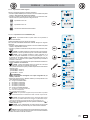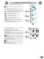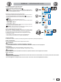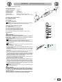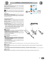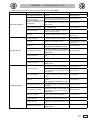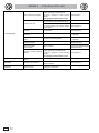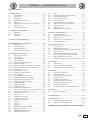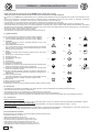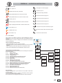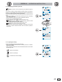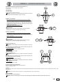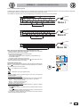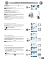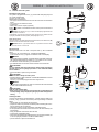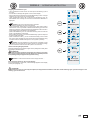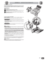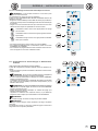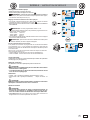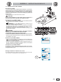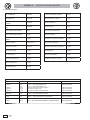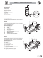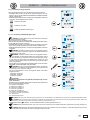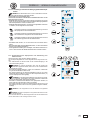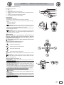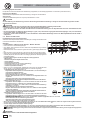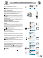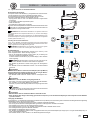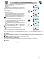
1
SKEMA 6
97050180
r e v. 0 0 5
12/2010
0051
ITALIANO (Lingua originale)..................................................................3
ENGLISH (translation from the original in Italian).............................77
FRANÇAIS (traduction de l'original en italien)................................151
DEUTSCH (Übersetzung aus dem Original in Italienisch)..............225
I
Gb
F
D
SKEMA 6 - ISTRUZIONI PER L'USO
Indice
1. Avvertenze generali .................................................................. 4
1.1.
Simbologia ....................................................................... 4
1.2.
Uso previsto e modalità di impiego .................................. 4
1.2.1.
Classificazione e normative di riferimento ....................... 4
1.2.2.
Condizioni ambientali ....................................................... 4
1.2.3.
Garanzia .......................................................................... 5
1.2.4.
Smaltimento a fine vita..................................................... 5
1.3.
Avvertenze di sicurezza ................................................... 5
1.4.
Pulizia e disinfezione. ...................................................... 6
2. Descrizione degli apparecchi .................................................. 7
2.1.
Targhette di identificazione ............................................. 7
2.2.
Riuniti ............................................................................... 7
2.3.
Poltrona............................................................................ 8
3. Accensione unità operatoria .................................................... 8
4. Funzionamento poltrona NEW SKEMA .................................... 8
4.1.
Dispositivi di sicurezza ..................................................... 9
4.2.
4.3.
4.4.
Dispositivi di emergenza .................................................. 9
Appoggiatesta regolabile ................................................. 9
Bracciolo mobile (Optional) .............................................. 9
5. Funzionamento tavoletta medico........................................... 10
5.1.
Consolle medico ............................................................ 12
5.1.1.
Interfaccia utente ........................................................... 13
5.1.1.1. Selezione operatore ....................................................... 14
5.1.1.2. Impostazioni generali ..................................................... 14
5.1.1.2.1. Regolazione luminosità display ..................................... 15
5.1.1.2.2. Selezione lingua ............................................................ 15
5.1.1.2.3. Regolazione/blocco freno braccio a pantografo ........... 16
5.1.1.2.4. Inserimento anagrafica operatore ................................. 17
5.1.1.2.5. Cronometro ................................................................... 17
5.1.1.2.6. Regolazione ora e data ................................................ 18
5.1.1.2.7. Selezione pulsante preferito ......................................... 18
5.1.1.2.8. Impostazione LAEC ...................................................... 18
5.1.1.3. Impostazioni sistemi di igiene ........................................ 19
5.1.1.3.1. Impostazione ciclo AUTOSTERIL (AS).......................... 19
5.1.1.3.2. Impostazione ciclo Time Flushing (TF) .......................... 20
5.1.1.3.3. Svuotamento serbatoio sistema M.W.B. ....................... 21
5.1.1.4. Impostazioni gruppo idrico ............................................. 21
5.1.1.4.1. Impostazione acqua alla bacinella................................. 22
5.1.1.4.2. Impostazione acqua al bicchiere ................................... 22
5.1.1.4.3. Impostazione movimentazioni automatiche bacinella ... 23
5.1.2.
Programmazione della "Posizione risciacquo" e
"Posizione di azzeramento" della poltrona..................... 23
5.1.3.
Programmazione delle posizioni 1, 2, 3 e 4 della poltrona 24
5.1.4.
Pulsante di emergenza. ................................................. 24
5.2.
Comando a piede........................................................... 24
5.2.1.
Comando a piede "multifunzione" .................................. 24
5.2.2.
Comando a piede "a pressione" .................................... 27
5.2.3.
Comando a piede "Power Pedal"................................... 28
5.3.
Siringa ........................................................................... 30
5.4.
Turbina ........................................................................... 31
5.5.
Micromotore elettrico ..................................................... 32
5.5.1.
Modalità di funzionamento CONSERVATIVE ................ 34
5.5.2.
Modalità di funzionamento ENDO.................................. 35
5.5.3.
Modalità di funzionamento SURGERY .......................... 36
5.5.4.
5.6.
5.6.1.
5.6.1.1.
5.6.1.2.
5.7.
5.8.
5.8.1.
5.9.
5.10.
5.11.
Menu impostazione rapporto di riduzione ...................... 37
Detartaratore .................................................................. 38
Detartaratore chirurgico SURGISON 2 .......................... 40
Modalità di funzionamento NORMAL............................. 40
Modalità di funzionamento BOOST ............................... 41
Lampada polimerizzante LEDA ..................................... 43
Telecamera endorale C-U2 PRO .................................. 44
Pannello di Controllo OSD (On Screen Display). ........... 48
Laser integrato L810 ..................................................... 49
Pompa peristaltica ........................................................ 50
Localizzatore apicale elettronico (LAEC). ..................... 51
6. Funzionamento tavoletta assistente...................................... 53
6.1.
Consolle tavoletta assistente ......................................... 53
6.2.
Strumenti a tavoletta assistente ..................................... 54
6.3.
Tubi di aspirazione ........................................................ 54
6.4.
Vassoio portatray a tavoletta assistente ........................ 55
6.5.
Aspirasaliva idraulico ..................................................... 55
7. Funzionamento gruppo idrico ................................................ 55
7.1.
Bacinella e riempimento bicchiere ................................. 55
7.2.
Sistema S.S.S. ............................................................... 57
7.2.1.
Ciclo di disinfezione manuale con acqua ossigenata. ... 58
7.3.
Sistema M.W.B. ............................................................ 59
7.4.
Sistema automatico di disinfezione AUTOSTERIL ....... 60
7.5.
Sistema S.H.D. per il lavaggio delle cannule di aspirazione.62
7.6.
Ciclo automatico TIME FLUSHING ............................... 63
7.7.
Apertura/chiusura carter laterale idrico .......................... 64
8. Accessori ................................................................................. 64
8.1.
Lampada scialitica ........................................................ 64
8.2.
Monitor / Workstation a palo lampada ........................... 64
8.3.
Attacchi rapidi aria/acqua/230V ..................................... 64
9. Manutenzione .......................................................................... 66
9.1.
Manutenzione degli strumenti ........................................ 66
9.2.
Scarico della condensa .................................................. 66
9.3.
Filtri aspirazione chirurgica ............................................ 66
9.4.
Aspirazione chirurgica.................................................... 67
9.5.
Separatore chirurgico CATTANI ..................................... 68
9.6.
Pulizia filtro aria di ritorno turbina................................... 69
9.7.
Separatore di amalgama METASYS ............................. 69
9.8.
Separatore di amalgama DÜRR .................................... 69
9.9.
Poltrona modello NEW SKEMA ..................................... 69
10. Imballaggio............................................................................. 70
10.1.
Trasporto ed immagazzinamento .................................. 70
11. Risoluzione dei problemi. ..................................................... 71
12. Dati tecnici ............................................................................. 72
12.1.
Caratteristiche dimensionali SKEMA 6 RS ................... 73
12.2.
Caratteristiche dimensionali SKEMA 6 CP .................. 74
13. Schema generale di igiene e manutenzione del
complesso odontoiatrico SKEMA 6 ..................................... 75
I
3
SKEMA 6 - ISTRUZIONI PER L'USO
1. Avvertenze generali
• Queste istruzioni descrivono come utilizzare correttamente i complessi odontoiatrici SKEMA 6.
Si prega di leggere attentamente questo manuale prima di utilizzare l'apparecchiatura.
• Queste istruzioni descrivono tutte le versioni delle unità operatorie SKEMA 6 e il massimo degli accessori possibili, pertanto non tutti i paragrafi
potranno trovare pratica applicazione nell'apparecchio acquistato.
• È vietata la riproduzione, la memorizzazione e la trasmissione in qualsiasi forma (elettronica, meccanica, mediante fotocopia, traduzione oppure
altri mezzi) di questa pubblicazione senza autorizzazione scritta da parte di CASTELLINI S.p.A.
• Le informazioni, le specifiche tecniche, le illustrazioni, contenute in questa pubblicazione non sono vincolanti.
CASTELLINI S.p.A. si riserva il diritto di apportare modifiche e miglioramenti tecnici senza modificare le presenti istruzioni.
• Il fabbricante persegue una politica di costante miglioramento dei propri prodotti, quindi è possibile che alcune istruzioni, specifiche e immagini
contenute in questo manuale possano differire leggermente dal prodotto acquistato. Il fabbricante inoltre si riserva il diritto di apportare qualsiasi
modifica a questo manuale senza preavviso.
• Il testo originale del presente manuale è in lingua italiana.
• Questa apparecchiatura é dotata di dispositivo anti-retrazione dei liquidi.
1.1.
Simbologia
Significato dei simboli utilizzati:
1) Tipo di protezione contro i contatti diretti e indiretti: Classe I.
Grado di protezione contro i contatti diretti e indiretti: Tipo B.
2) ATTENZIONE!
Indica una situazione in cui la mancata osservanza delle istruzioni
potrebbe provocare un guasto all'apparecchio o danni all'utilizzatore
e/o al paziente.
3) ISTRUZIONI PER IL FUNZIONAMENTO:
Indica la necessità di consultare il manuale di uso prima di utilizzare
quella parte di apparecchiatura.
4) NOTA:
Indica delle informazioni importanti per l'utilizzatore e/o per il personale
di assistenza tecnica.
5) Contatto di messa a terra di protezione.
6) Corrente alternata.
7) Parte sterilizzabile in autoclave.
8) Apparecchiatura accesa
9) Apparecchiatura spenta
10) Acceso (una parte dell'apparecchiatura).
11) Spento (una parte dell'apparecchiatura).
12) Apparecchiatura conforme ai requisiti stabiliti dalla direttiva CE 93/42 e
successive modifiche intervenute ( Apparecchiature in Classe IIa ).
13) Apparecchiatura conforme ai requisiti stabiliti dalla direttiva CE 93/42
successive modifiche intervenute ( Apparecchiature in Classe I ).
14) Simbolo per lo smaltimento ai sensi delle Direttive 2002/95/ EC, 2002/96/
EC e 2003/108/ EC.
15) “Attenzione pericolo biologico”.
Fornisce l’indicazione di possibili rischi di contaminazione da contatto
con fluidi, depositi biologici infetti.
16) Fabbricante.
17) Mese e anno di fabbricazione dell'apparecchiatura.
18) Numero di matricola dell'apparecchiatura.
19) Marchio DVGW (Marchio di Qualità relativo alla fornitura dell’acqua
potabile).
1
8
15
2
9
16
3
10
17
4
11
18
5
12
6
13
7
135°C
0051
19
14
1.2. Uso previsto e modalità di impiego
• Le unità operatorie della serie SKEMA linea 6, modello SKEMA 6 e SKEMA 6 CP sono apparecchiature ad uso medico destinate al trattamento
odontoiatrico.
• La tavoletta medico può essere equipaggiata con un massimo di 6 strumenti.
• La tavoletta assistente può essere equipaggiata con 2 cannule di aspirazione e 3 strumenti.
• Questa apparecchiatura deve essere utilizzata solo da personale (medico e paramedico) adeguatamente addestrato.
• Apparecchio previsto per funzionamento continuo con carichi intermittenti (si vedano i tempi delle singole parti nelle sezioni dedicate).
1.2.1. Classificazione e normative di riferimento
• Classificazione DISPOSITIVI MEDICI
Classificazione del complesso odontoiatrico secondo le regole indicate nell'allegato IX della Direttiva 93/42/CE e successive modifiche intervenute:
Classe IIa.
• Classificazione DISPOSITIVI ELETTROMEDICALI
Classificazione dell’apparecchiatura secondo la norma EN 60601-1 per la sicurezza di apparecchiature mediche: Classe I - Tipo B.
• Normative di riferimento: le unità operatorie della serie SKEMA 6 sono apparecchiature progettate in conformità alle norme CEI EN 60601-1, CEI EN
60601-1-2, ISO 7494, ISO 6875 e EN 1717 (tipo AA e AB) per quanto riguarda i dispositivi per la sicurezza della rete idrica.
1.2.2. Condizioni ambientali
L'apparecchiatura deve essere installata in ambienti con le seguenti condizioni:
• temperatura da 10 a 40°C;
• umidità relativa da 30 al 75%;
• pressione atmosferica da 700 a 1060 hPa;
• pressione dell'aria all'entrata nella apparecchiatura compresa tra 6-8 Bar;
• durezza dell'acqua all'entrata nella apparecchiatura non superiore a 60 mg/l;
• pressione dell'acqua all'entrata nella apparecchiatura compresa tra 3-5 Bar;
• temperatura dell'acqua all'entrata nella apparecchiatura non superiore ai 25°C.
4
I
SKEMA 6 - ISTRUZIONI PER L'USO
1.2.3. Garanzia
CASTELLINI S.p.A. garantisce per la sicurezza l’affidabilità e le prestazioni degli apparecchi.
La garanzia è condizionata al rispetto delle seguenti prescrizioni:
• Osservanza delle condizioni riportate sul certificato di garanzia.
• Esecuzione della manutenzione annuale programmata.
• L’apparecchiatura deve essere utilizzata esclusivamente secondo le istruzioni riportate nel presente libretto.
• L’impianto elettrico dell’ambiente in cui viene installata l’apparecchiatura deve essere conforme alle norme I.E.C. 60364-7-710 (Norme relative agli
impianti elettrici di locali adibiti ad uso medico).
• L'apparecchio deve essere alimentato con una linea 3x1,5 mm2 protetta da un interruttore magnetotermico bipolare conforme alle relative normative
(10 A, 250 V, potere di interruzione almeno 6000 A, distanza fra i contatti almeno 3 mm).
ATTENZIONE!
Il colore dei tre conduttori (LINEA, NEUTRO e TERRA) deve corrispondere a quanto prescritto dalle Norme.
• Il montaggio, le riparazioni, l' ampliamento dell' apparecchio, le tarature e in generale tutte le operazioni che comportano l’apertura dei cofani
dell’apparecchiatura devono essere effettuate esclusivamente da tecnici autorizzati da CASTELLINI.
1.2.4. Smaltimento a fine vita
Ai sensi delle Direttive 2002/95/ EC, 2002/96/ EC e 2003/108/ EC, relative alla riduzione dell’uso di sostanze pericolose nelle apparecchiature elettriche
ed elettroniche, nonché allo smaltimento dei rifiuti è fatto obbligo di non smaltire questi ultimi come rifiuti urbani, effettuandone la raccolta separata. Al
momento dell’acquisto di una nuova apparecchiatura di tipo equivalente, in ragione di uno a uno, l’apparecchiatura giunta a fine vita dovrà essere riconsegnata al rivenditore per lo smaltimento. Con riguardo al reimpiego, reciclaggio e alle altre forme di recupero dei rifiuti di cui sopra, il produttore svolge le
funzioni definite dalle singole Legislazioni Nazionali. L’adeguata raccolta differenziata per l’avvio successivo dell’apparecchiatura dismessa al riciclaggio,
al trattamento e allo smaltimento ambientalmente compatibile contribuisce ad evitare possibili effetti negativi sull’ambiente e sulla salute e favorisce il riciclo
dei materiali di cui è composta l’apparecchiatura. Il simbolo del cassonetto barrato riportato sull’apparecchiatura indica che il prodotto alla fine della propria
vita utile deve essere raccolto separatamente dagli altri rifiuti.
ATTENZIONE!
Lo smaltimento abusivo del prodotto comporta l’applicazione delle sanzioni definite dalle singole Legislazioni Nazionali.
1.3. Avvertenze di sicurezza
ATTENZIONE!
• L'installazione di tutti gli apparecchi è sempre di tipo permanente.
In base al tipo di poltrona cui il riunito è abbinato riferirsi all'apposita DIMA di installazione indicata al paragrafo "Dati Tecnici".
CASTELLINI S.p.A. declina ogni responsabilità per danni a cose e persone qualora non venga rispettata la presente clausola.
• Condizione del pavimento.
Le condizioni del pavimento (di tipo continuo), devono essere conformi alle norme di portata secondo DIN 1055 foglio 3.
Il peso del complesso dentale compreso di paziente da 190Kg, è uguale c.a 350Kg/mq.
• Il tecnico non autorizzato da CASTELLINI che procede a modificare il prodotto sostituendo parti o componenti con altri diversi da quelli utilizzati dal
costruttore, si assume una responsabilità analoga a quella del costruttore stesso.
CASTELLINI S.p.A. declina ogni responsabilità per danni a cose e persone qualora non venga rispettata la presente clausola.
• Poltrona.
Il carico massimo ammesso sulla poltrona è di 190 Kg. Questo valore non deve essere superato.
• Superficie di appoggio dei trays.
Non devono essere superati i valori di carico massimo di seguito indicati:
- portatray applicato alla tavoletta medico, carico massimo ammesso sul vassoio 2 Kg. distribuito.
- portatray applicato alla tavoletta assistente, carico massimo ammesso sul vassoio 1 Kg. distribuito.
• Collegamenti a strumenti esterni.
L'apparecchio può essere collegato elettricamente solo ad altri strumenti provvisti di marchio CE.
• Interferenze elettromagnetiche.
L'utilizzo nello studio o nelle immediate vicinanze di apparecchi elettrici non conformi alla normativa I.E.C. 60601-1-2, potrebbe causare interferenze
elettromagnetiche o di altra natura, provocando malfunzionamenti del complesso odontoiatrico.
In questi casi si raccomanda di togliere preventivamente l'alimentazione del complesso odontoiatrico prima di utilizzare tali apparecchiature.
• Sostituzione delle frese.
Azionare i dispositivi di sbloccaggio delle turbine e dei contrangoli soltanto quando la fresa è completamente ferma. In caso contrario il sistema
di bloccaggio si deteriora e le frese possono sganciarsi provocando ferimenti.
Usare esclusivamente frese di qualità con lo stelo di attacco di
diametro calibrato. Per verificare lo stato del dispositivo di bloccaggio, controllare ogni giorno, all' inizio del lavoro, che la fresa sia bloccata saldamente allo strumento. I difetti al sistema di bloccaggio dovuti ad uso non corretto sono facilmente riconoscibili e non sono coperti da garanzia.
• Pazienti portatori di cardiostimolatore e/o protesi acustiche.
Nel trattamento dei pazienti portatori di cardiostimolatore e/o protesi acustiche occorre considerare i possibili effetti degli strumenti utilizzati sul
cardiostimolatore e/o sulla protesi acustica. A questo scopo si rimanda alla letteratura tecnico-scientifica sull’argomento.
• Implantologia.
Nel caso che il complesso odontoiatrico venga impiegato per interventi di implantologia utilizzando apparecchiature autonome e finalizzate a questo
intervento si raccomanda di togliere l'alimentazione della poltrona onde evitare possibili movimenti indesiderati causati da guasti e/o attivazioni
accidentali dei comandi di movimentazione.
• Prima di lasciare l’ambulatorio disinserire l'alimentazione idrica dello studio e l’interruttore generale dell'apparecchiatura.
• L’apparecchio non è protetto contro la penetrazione di liquidi (IPX 0).
• L’apparecchio non è adatto ad un uso in presenza di una miscela di gas anestetico infiammabile con ossigeno o protossido d’azoto.
• L’apparecchiatura dovrà essere custodita e conservata in perfetta efficienza. Il costruttore declina ogni responsabilità (civile e penale) per qualsiasi
abuso, trascuratezza nell’uso o uso improprio dell’apparecchiatura.
• L’apparecchiatura dovrà essere utilizzata esclusivamente da personale autorizzato (medico e paramedico) adeguatamente addestrato.
• L’apparecchiatura dovrà essere sempre presidiata quando accesa o predisposta all’avviamento, in particolare non dovrà mai essere lasciata incustodita in presenza di minori / incapaci o in genere di personale non autorizzato all’utilizzo.
Eventuale personale accompagnatore deve rimanereal di fuori dell'area in cui viene effettuato il trattamento e comunque sotto la responsabilità
dell'operatore. Per area in cui viene effettuato il trattamento si intende lo spazio circostante il complesso odontoiatrico aumentato di 1,5 mt.
• Rispetto della qualità dell'acqua.
Al fine di soddisfare i requisiti legali medici e nazionali relativi all'acqua proveniente dai riuniti, CASTELLINI S.p.A. consiglia di dotare il complesso
odontoiatrico di un impianto di disinfezione.
L'utente del complesso odontoiatrico è responsabile della qualità dell'acqua e deve, se necessario, adottare provvedimenti alternativi volti al mantenimento della stessa nel caso il complesso odontoiatrico venga utilizzato senza impianto di disinfezione.
I
5
SKEMA 6 - ISTRUZIONI PER L'USO
Una volta che il riunito è stato installato nello studio odontoiatrico e l'acqua ha riempito i condotti, l'apparecchiatura è esposta al rischio di contaminazione da parte di microrganismi acquatici provenienti dalla rete municipale, in grado di instaurare un biofilm nel lume delle condotte. Per questo
motivo, si raccomanda di eseguire l'installazione del riunito solo nel momento di cui esso comincia ad essere utilizzato quotidiana mente, e di
eseguire le procedure di decontaminazione con la frequenza prescritta fin dal primo giorno di installazione.
NOTA: contattare il proprio rivenditore o la propria Associazione Dentisti competente per informazioni sui requisiti e provvedimenti nazionali.
1.4. Pulizia e disinfezione.
Pulire è il primo passo necessario per qualunque processo di disinfezione.
L’azione fisica di sfregare con detergenti e tensioattivi e di sciacquare con acqua rimuove un numero consistente di microrganismi. Se una superficie
non è prima pulita, il processo di disinfezione non può avere successo.
Quando una superficie non può essere adeguatamente pulita, dovrebbe essere protetta con le barriere.
Le parti esterne dell’apparecchiatura devono essere pulite e disinfettate utilizzando un prodotto per uso ospedaliero con indicazioni per HIV, HBV e
tubercolocide (di livello medio) specifico per piccole superfici.
La grande varietà di farmaci e prodotti chimici utilizzati nello studio odontoiatrico possono danneggiare le superfici verniciate e le parti in materiale
plastico. Le prove e le ricerche effettuate hanno dimostrato che le superfici non possono essere completamente protette dall’aggressione di tutti i
prodotti reperibili sul mercato. Si raccomanda quindi di utilizzare protezioni a barriera ogni qual volta possibile.
Gli effetti aggressivi dei prodotti chimici dipendono anche dal tempo di permanenza sulle superfici.
È pertanto importante non lasciare il prodotto prescelto sulle superfici dell’apparecchio oltre il tempo prescritto dal fabbricante.
Data l’aggressività dei principi attivi utilizzati nei disinfettanti, si raccomanda di utilizzare prodotti che contengano come massimo:
• Etanolo al 96%. Concentrazione: massimo 30 g. per ogni 100 g. di disinfettante.
• Propanolo. Concentrazione: massimo 20 g. per ogni 100 g. di disinfettante.
• Combinazione di etanolo e propanolo. Concentrazione: la combinazione dei due deve essere come massimo 40 g. per ogni 100 g. di disinfettante.
CASTELLINI S.p.A. ha eseguito varie prove di compatibilità fra i principali disinfettanti sul mercato e i propri prodotti, i disinfettanti che sono risultati
essere più idonei sono i seguenti:
• Superfici in materiale plastico, superfici verniciate e non verniciate.
- STER 1 PLUS ( Castellini ).
• Tappezzerie.
- RelyOn Virkosept ( Du Pont ).
- Plastisept ( Alpro ).
- Zeta 3 Foam ( Zhermack ).
ATTENZIONE!
La tappezzeria VISCO si macchia con gli schizzi di acido per mordenzare.
Si raccomanda, qualora ci dovessero essere degli schizzi di acido, di sciacquare subito con abbondante acqua.
•
•
•
•
•
•
ATTENZIONE!
Non utilizzare prodotti contenenti alcool isopropilico (2-propanolo, iso-propanolo).
Non utilizzare prodotti contenenti ipoclorito di sodio (candeggina).
Non utilizzare prodotti contenenti fenoli.
Non vaporizzare il prodotto scelto direttamente sulle superfici dell’apparecchio.
Non combinare tra loro o con liquidi diversi i sopraelencati prodotti.
L’ uso di qualsiasi prodotto deve essere fatto nel rispetto delle disposizioni date dal fabbricante.
Istruzioni per la pulizia e la disinfezione.
Per la pulizia e la disinfezione utilizzare carta monouso morbida, non abrasiva (evitare di utilizzare carta riciclata), oppure garza sterile.
Si sconsiglia l’uso di panni spugna e comunque di qualunque materiale riutilizzabile.
ATTENZIONE!
• Si raccomanda di spegnere il complesso odontoiatrico prima di eseguire le operazioni di pulizia e disinfezione delle parti esterne.
• Ciò che viene utilizzato per la pulizia e la disinfezione deve essere gettato via al termine dell’operazione.
6
I
SKEMA 6 - ISTRUZIONI PER L'USO
2. Descrizione degli apparecchi
2.1. Targhette di identificazione
Unità operatoria.
La targhetta si trova sul braccio di collegamento tra poltrona e gruppo
idrico.
Dati riportati sulla targhetta:
• Nome del costruttore.
• Nome dell'apparecchiatura.
• Tensione nominale.
• Tipo di corrente.
• Frequenza nominale.
• Potenza massima assorbita.
• Numero di serie.
• Mese e anno di fabbricazione.
CASTELLINI S.p.A. - V. SALICETO, 22
CASTEL MAGGIORE (BO) - ITALY
0051
MADE IN ITALY
IT
SKEMA 6
230 V~ 50/60 Hz 1500 W
SN
2.2. Riuniti
I complessi odontoiatrici modello SKEMA 6 sono previsti nelle seguenti
versioni:
Versione RS.
Tavoletta medico in versione RS (gli strumenti sono recuperati mediante
un sistema di braccetti a molla) applicata su doppio braccio di cui uno
articolato ed autobilanciato.
Descrizione delle varie parti:
[ a ] Gruppo idrico.
[ b ] Braccio orientabile.
[ c ] Tavoletta medico.
[ d ] Consolle comandi medico.
[ e ] Tavoletta porta tray.
[ f ] Tavoletta assistente.
[ g ] Consolle di comando tavoletta assistente.
[ h ] Contenitore allacciamenti.
[ i ] Comando a piede multifunzionale.
[ l ] Erogatore acqua al bicchiere.
[ m ] Bacinella.
[ n ] Braccio autobilanciato.
[ q ] Tavoletta porta tray su tavoletta assistente ( optional ).
l m a
f
b
n
q g
c
d
e
h
i
Versione CP
Tavoletta medico versione CP (gli strumenti sono inseriti verticalmente in
apposite sedi) applicata su doppio braccio di cui uno articolato ed autobilanciato.
Descrizione delle varie parti:
[ a ] Gruppo idrico.
[ b ] Braccio orientabile.
[ c ] Tavoletta medico.
[ d ] Consolle comandi medico.
[ e ] Tavoletta porta tray ( optional ).
[ f ] Tavoletta assistente.
[ g ] Consolle di comando tavoletta assistente.
[ h ] Contenitore allacciamenti.
[ i ] Comando a piede multifunzionale.
[ l ] Erogatore acqua al bicchiere.
[ m ] Bacinella.
[ n ] Braccio autobilanciato.
[ q ] Tavoletta porta tray su tavoletta assistente ( optional ).
[ r ] Negatoscopio per panoramiche ( optional ).
l m a
b
e
f
q g
n
r
c
d
h
i
I
7
SKEMA 6 - ISTRUZIONI PER L'USO
2.3. Poltrona
a
Descrizione delle varie parti.
[ a ] Poggiatesta.
[ b ] Schienale
[ c ] Bracciolo sinistro mobile ( optional ).
[ d ] Bracciolo destro mobile ( optional ).
[ e ] Pedana di sicurezza.
[ f ] Pedana poggiapiedi scorrevole.
b
Tempi di funzionamento.
I tempi di funzionamento e riposo prescritti sono i seguenti:
lavoro 25 sec. - riposo 10 min.
c
d
f
Carico massimo ammesso.
Il carico massimo ammesso sulla poltrona è di 190 Kg.
e
ATTENZIONE!
Questo valore non deve essere superato.
Note sulla biocompatibilità.
Per le imbottiture rivestite in skai devono essere utilizzati solo ricambi
originali CASTELLINI.
3. Accensione unità operatoria
Agire sull'interruttore generale ( f ):
Apparecchiatura accesa:
- impianto elettrico alimentato
- impianto pneumatico collegato
- impianto idrico collegato
f
Apparecchiatura spenta:
- impianto elettrico non alimentato
- impianto pneumatico non collegato
- impianto idrico non collegato
4. Funzionamento poltrona NEW SKEMA
La poltrona NEW SKEMA esegue i seguenti movimenti:
• Salita/discesa del sedile
• Salita/discesa dello schienale con inclinazione del sedile (Trendelemburg compensato)
a
La poltrona può essere comandata dai seguenti punti:
• Tavoletta medico [ a ] (vedi par. 5.).
• Comando a piede multifunzione [ b ] (vedi par. 5.2.).
• Tavoletta assistente [ c ] (vedi par. 6.).
La pedana poggiapiedi [ f ] può essere estratta per circa 10
cm.
Blocco movimenti poltrona.
Con gli strumenti a riposo, premendo il pulsante MED per almeno 5
secondi, vengono disabilitati/abilitati i movimenti della poltrona.
L'avvenuta disabilitazione viene evidenziata dall’apposita icona (
A ) sul display consolle.
8
I
b
f
c
SKEMA 6 - ISTRUZIONI PER L'USO
4.1. Dispositivi di sicurezza
L'apparecchiatura dispone dei seguenti dispositivi di sicurezza:
• La pedana della poltrona è dotata di un dispositivo [ l ] che, in presenza di
un ostacolo, blocca immediatamente il movimento di discesa della poltrona
ed esegue un movimento automatico di risalita per liberare l'ostacolo.
• Lo schienale della poltrona è dotato di un dispositivo [ m ] che, in presenza di un ostacolo, blocca immediatamente il movimento di discesa dello
schienale ed esegue un movimento automatico di risalita per liberare
l'ostacolo.
• I bracci della tavoletta assistente sono dotati di un dispositivo di sicurezza
[ n ] che, in presenza di un ostacolo, blocca immediatamente il movimento
di discesa della poltrona ed esegue un movimento automatico di risalita
per liberare l'ostacolo.
m
n
l
4.2. Dispositivi di emergenza
ATTENZIONE!
Nel caso si debba bloccare il movimento dell'apparecchiatura agire
sui seguenti dispositivi:
• Pulsanti di movimentazioni poltrona [ a ] o [ c ].
Azionando un qualsiasi pulsante di movimentazione poltrona ogni tipo di
movimento dell'apparecchiatura verrà bloccato.
• Comando a piede [ b ].
Azionando il comando a piede ogni tipo di movimento dell'apparecchiatura
verrà bloccato.
• Pedana della poltrona [ i ].
Azionando la pedana della poltrona: ogni tipo di movimento dell'apparecchiatura verrà bloccato.
a
b
l
c
4.3. Appoggiatesta regolabile
L'appoggiatesta può essere di 2 tipi:
1
con bloccaggio cuscino di tipo manuale
2
con bloccaggio cuscino di tipo pneumatico
Regolazione altezza poggiatesta.
Il posizionamento dell'asta del poggiatesta è ottenuto per mezzo di una frizione
magnetica.
L'operatore deve sollevare e/o spingere in basso il poggiatesta fino al raggiungimento della posizione desiderata.
Regolazione orientamento del cuscino.
• Con bloccaggio di tipo manuale ( 1 ) :
Ruotare in senso antiorario il pomello di blocco ( k ), posizionare il cuscino
come desiderato e poi avvitare nuovamente il pomello di blocco.
• Con bloccaggio di tipo pneumatico ( 2 ):
Agire sul pulsante di blocco ( u ) e, mantenendolo premuto, posizionare il
cuscino come desiderato. Una volta trovato la posizione corretta è sufficiente
rilasciare il pulsante ( u ) per bloccare nuovamente il cuscino.
NOTA: il dispositivo di bloccaggio è attivo solo quando il circuito
dell'aria è in pressione.
1
k
2
u
Avvertenze di utilizzo.
ATTENZIONE!
• Carico massimo applicabile sull'appoggiatesta: 30 Kg.
• Non modificare l'orienta mento del cuscino senza aver disattivato il dispositivo di bloccaggio.
• Onde evitare movimenti incontrollati dell'appoggiatesta si consiglia di
sorreggerlo con entrambe le mani prima di disattivare il dispositivo di
bloccaggio.
4.4. Bracciolo mobile (Optional)
Ribaltamento del bracciolo mobile.
Ruotare in senso orario il bracciolo mobile fino a portarlo verso il basso onde
facilitare l’accesso e l’uscita del paziente.
Rimozione del bracciolo mobile.
Portare il bracciolo in posizione verticale e sfilarlo dal sedile.
ATTENZIONE!
Carico massimo applicabile sul bracciolo della poltrona: 35 Kg.
I
9
SKEMA 6 - ISTRUZIONI PER L'USO
5. Funzionamento tavoletta medico
Disposizione degli strumenti.
La disposizione degli strumenti sulla tavoletta è definita dal cliente in fase
di ordine.
Attivazione degli strumenti.
• La siringa è sempre attiva (vedi paragrafo 5.3.).
• La lampada polimerizzante si attiva con l'apposito tasto a strumento
estratto (vedi paragrafo 5.7.).
• La telecamera endorale C-U2 PRO si attiva a strumento estratto (vedi
paragrafo 5.8.).
• Il laser integrato L810 una volta estratto, viene azionato tramite il comando
a piede (vedi paragrafo 5.9.).
• Tutti gli altri strumenti, una volta estratti, vengono azionati tramite il comando a piede (vedi paragrafo 5.2.).
Interdipendenza degli strumenti.
L’uso simultaneo degli strumenti è impedito da un dispositivo di interdipendenza.
Il primo strumento estratto è operativo mentre quelli estratti successivamente sono disattivati dal dispositivo di interdipendenza.
Il dispositivo di interdipendenza permette di sostituire la fresa su uno strumento mentre un altro viene impiegato sul paziente.
Posizionamento della tavoletta medico.
La tavoletta medico è mobile in tutte le direzioni.
Per regolare l’altezza della tavoletta e/o il suo orientamento sul piano orizzontale è sufficiente impugnare la maniglia [ a ].
NOTA per sbloccare il freno pneumatico del braccio a pantografo
occorre impugnare la maniglia appoggiando il pollice sul punto ( B ).
a
B
A
Dispositivo di arresto braccetti richiamo strumenti (solo versione
SPRIDO).
Qualora sia previsto tale dispositivo è possibile bloccare il braccetto di
richiamo strumento nella posizione di strumento estratto.
L'inserimento del dispositivo è evidenziato da uno scatto meccanico che
avviene a circa 2/3 della corsa totale del braccetto.
Per ripristinare la condizione originaria è sufficiente portare il braccetto a
fine corsa ( A ).
Vassoio portatray applicato alla tavoletta medico.
Il supporto strumenti [ q ] è asportabile e può essere sterilizzato in autoclave a 135°.
q
ATTENZIONE!
Carico massimo ammesso sul vassoio portatray: 2 Kg distribuito.
Pulizia maniglia tavoletta medico.
Togliere la maniglia [ d ] tirandola verso l'esterno dopo aver premuto il
pulsante di sblocco [ e ].
Pulire la maniglia tavoletta utilizzando un prodotto idoneo, che sia stato
provato efficace contro batteri e funghi, ed ampiamente efficace verso i
virus (compresi HBV e HIV); vedere il paragrafo 1.4.
NOTA: il prodotto deve essere spruzzato su carta morbida mono
uso o garza sterile.
ATTENZIONE!
Non impiegare prodotti abrasivi o acidi.
10
I
d
e
SKEMA 6 - ISTRUZIONI PER L'USO
Pulizia tavoletta medico.
Per la pulizia della tavoletta medico utilizzare un prodotto idoneo, che sia
stato provato efficace contro batteri e funghi, ed ampiamente efficace verso
i virus (compresi HBV e HIV); vedere il paragrafo 1.4.
z
ATTENZIONE!
Non impiegare prodotti abrasivi o acidi.
NOTA tavolette versione RS: il supporto strumenti [ u ] e la copertura cordoni [ z ] sono anche sterilizzabili in autoclave a 135°.
NOTA tavolette versione CP: la protezione tavoletta [ v ] è sterilizzabile in autoclave a 135°.
Cordoni strumento removibili.
Tutti gli strumenti sono dotati di cordoni removibili per agevolare la loro
pulizia.
Per togliere i cordoni degli strumenti occorre procedere come segue:
Tavolette versione RS
• aprire la parte frontale della tavoletta, dopo averla sbloccata agendo come
da figura sul pulsante [ k ] posto dietro alla consolle;
• togliere i cordoni dopo aver svitato le relative ghiere di fissaggio in plastica.
Tavolette versione CP
Togliere i cordoni dopo aver svitato le relative ghiere di fissaggio in plastica
poste sotto la tavoletta.
u
k
ATTENZIONE!
• Spegnere l'unità operatoria prima di eseguire l'operazione di rimozione
dei cordoni strumento.
• Dopo avere spento l'unità operatoria, svuotare le condotte della siringa
premendo i relativi pulsanti aria e acqua direttamente sulla bacinella
fino al termine della fuoriuscita di acqua spray.
• I cordoni degli strumenti TURBINA, MICROMOTORE e DETARTARATORE contengono acqua, di conseguenza si consiglia di eseguire l'operazione di smontaggio del cordone tenendo l'estremità lato manipolo
posizionata sulla bacinella.
• Quando si rimonta un cordone occorre assicurarsi che i contatti elettrici
siano asciutti e che la ghiera di fissaggio in plastica sia stretta bene.
• Ogni cordone deve essere rimontato solo ed esclusivamente nella
sede dello strumento corrispondente.
Per la pulizia dei cordoni strumenti utilizzare un prodotto idoneo, che sia
stato provato efficace contro batteri e funghi, ed ampiamente efficace verso
i virus (compresi HBV e HIV); vedere il paragrafo 1.4.
ATTENZIONE!
I cordoni degli strumenti NON sono idonei ad essere messi in autoclave
o ad essere sterilizzati a freddo per immersione.
I
11
SKEMA 6 - ISTRUZIONI PER L'USO
5.1. Consolle medico
Descrizione dei pulsanti:
Pulsante richiamo/cambio menu.
Dr. Rossi
Pulsanti multifunzione.
Pulsante di selezione rapida 100% dei valori impostabili.
Pulsante di selezione rapida 50% dei valori impostabili.
Pulsante di selezione rapida 1% dei valori impostabili.
Pulsante AUMENTA: incrementa i valori impostabili.
Pulsante DIMINUISCI: decrementa i valori impostabili.
Pulsante accensione/spegnimento illuminazione a Fibre Ottiche
(on/off).
Pulsante comando inversione senso di rotazione
del micromotore.
Pulsante di accensione/spegnimento lampada operatoria
Pulsante memorizzazione funzioni poltrona.
Pulsante comando di erogazione acqua al bicchiere.
Pulsante richiamo posizione ritorno automatico.
Pulsante comando di erogazione acqua alla bacinella.
Pulsante richiamo posizione risciacquo.
Pulsante comando solo acqua agli spray agli strumenti.
Pulsante richiamo posizione di emergenza.
Pulsante inserimento/esclusione sistema S.S.S.
Pulsante salita sedile e richiamo posizione programmata 1.
Pulsante chiamata assistente.
Pulsante salita schienale e richiamo posizione programmata 2.
Pulsante comando movimentazione bacinella in senso antiorario
( attivo solo con bacinella motorizzata ).
Pulsante discesa sedile e richiamo posizione programmata 3.
Pulsante comando movimentazione bacinella in senso orario
( attivo solo con bacinella motorizzata ).
Pulsante discesa schienale e richiamo posizione programmata 4.
Pulsante attivazione pompa peristaltica
( attivo solo se presente la pompa peristaltica ).
NOTA: funzionamento dei pulsanti di movimentazione poltrona
• Breve pressione: attivazione movimento automatico di richiamo della posizione programmata.
• Pressione prolungata: attivazione movimento di posizionamento manuale.
12
I
SKEMA 6 - ISTRUZIONI PER L'USO
Descrizione icone di segnalazione.
Freno braccio a pantografo bloccato.
Sistema S.S.S. attivo.
Pompa peristaltica inserita.
Serbatoio acqua distillata NON in pressione.
Memorizzazione poltrona attivata.
(Colore nero) Serbatoio acqua distillata in riserva ed attivo.
Programma automatico 1 poltrona.
(Colore rosso) Serbatoio acqua distillata in riserva ma NON attivo.
Programma automatico 2 poltrona.
Sistema M.W.B. attivo.
Programma automatico 3 poltrona.
(Colore nero) Serbatoio acqua ossigenata in riserva ed attivo.
Programma automatico 4 poltrona.
(Colore rosso) Serbatoio acqua ossigenata in riserva ma NON attivo.
Programma automatico posizione risciacquo poltrona.
Acqua al bicchiere FREDDA.
Programma automatico posizione di azzeramento poltrona.
Acqua al bicchiere TIEPIDA.
Movimenti poltrona bloccati.
Acqua al bicchiere CALDA.
5.1.1. Interfaccia utente
All’accensione, il complesso odontoiatrico esegue un breve ciclo di autodiagnosi che termina quando sul display compare la videata principale riportante
il nome dell'ultimo operatore impostato.
Da questo momento è possibile variare alcune impostazioni dell’unità operatoria utilizzando un semplice sistema di menu (vedi schema a lato).
Comandi di navigazione tra i vari menu.
• Per spostarsi da un'icona all'altra premere il pulsante MENU.
• Dopo aver selezionato un'icona, per entrare nel relativo sottomenu premere il pulsante muntifunzione OK.
• Per tornare alla videata precedente premere il pulsante muntifunzione
ESC.
• Per variare i valori impostabili premere i pulsanti AUMENTA e/o DIMINUISCI.
Struttura del menu di interfaccia utente.
Il menu di interfaccia utente è strutturato come da schema a lato ed è composto
dai seguenti menu:
5.1.1.1.
Selezione operatore.
5.1.1.2.
IMPOSTAZIONI GENERALI.
5.1.1.2.1. Regolazione contrasto display.
5.1.1.2.2. Selezione lingua.
5.1.1.2.3. Regolazione/blocco freno braccio a pantografo.
5.1.1.2.4. Inserimento anagrafica operatore.
5.1.1.2.5. Cronometro.
5.1.1.2.6. Regolazione ora.
5.1.1.2.7. Selezione pulsante preferito.
5.1.1.2.8. Impostazione LAEC (solo con LAEC).
5.1.1.3.
IMPOSTAZIONE SISTEMI DI IGIENE.
5.1.1.3.1. Impostazione ciclo di disinfezione (solo con sistema AUTOSTERIL).
5.1.1.3.2. Impostazione ciclo Time Flushing (solo con Time Flushing).
5.1.1.3.3. Svuotamento serbatoio M.W.B. (solo con sistema M.W.B.).
5.1.1.4.
IMPOSTAZIONI GRUPPO IDRICO.
5.1.1.4.1. Impostazione erogazione acqua alla bacinella.
5.1.1.4.2. Impostazione erogazione acqua al bicchiere.
5.1.1.4.3. Gestione movimentazioni (solo con bacinella motorizzata).
Dr. Rossi
15:24
5.1.1.1.
5.1.1.2.
5.1.1.2.1.
5.1.1.3.1.
5.1.1.2.2.
5.1.1.4.1.
5.1.1.3.2.
5.1.1.2.3.
5.1.1.4.2.
5.1.1.3.3.
5.1.1.2.4.
5.1.1.3.
5.1.1.4.
5.1.1.2.5.
5.1.1.4.3.
5.1.1.2.6.
5.1.1.2.7.
Messaggi di errore.
Durante il ciclo iniziale di autodiagnosi, il complesso odontoiatrico potrebbe
rilevare dei malfunzionamenti nell’impiantistica interna.
In tal caso sul display viene mostrato un messaggio di errore che resta visibile
sino a che l’operatore non preme il pulsante OK. (vedere paragrafo 11.).
Se il malfunzionamento non è pericoloso il complesso odontoiatrico rimane
comunque funzionante.
5.1.1.2.8.
I
13
SKEMA 6 - ISTRUZIONI PER L'USO
5.1.1.1. Selezione operatore
La consolle dei complessi odontoiatrici modello SKEMA 6 consente di
impostare 3 diversi operatori.
I dati impostabili per ogni operatore sono i seguenti:
• Nome dell’operatore.
• Regolazione della potenza della turbina e del detartaratore.
• 4 modalità operative per il micromotore elettrico.
• Accensione e regolazione delle fibre ottiche di ogni strumento.
• Controllo incrementale o ON/OFF della potenza della turbina e del detartaratore.
• I programmi automatici di movimentazione della poltrona.
• La soglia di allarme del localizzatore apicale elettronico LAEC.
Selezione dell’operatore.
La consolle consente di selezionare 3 diversi operatori identificabili
ognuno con uno specifico nome di massimo 20 caratteri (vedi paragrafo
5.1.1.2.4.)
Dalla videata principale premere ripetutamente il pulsante multifunzione
in corrispondenza dell'icona (
) fino al raggiungimento dell’operatore
desiderato.
Dr. Bianchi
Dr. Rossi
15:24
15:24
Dr. Verdi
15:24
NOTA: la variazione dell’operatore avviene in maniera ciclica ogni
volta si preme il pulsante multifunzione.
5.1.1.2. Impostazioni generali
Dalla videata principale eseguire le seguenti operazioni:
• Premere il pulsante MENU per entrare nel menu principale dove sono
presenti le seguenti icone:
IMPOSTAZIONI GENERALI
Dr. Rossi
15:24
IMPOSTAZIONI SISTEMI DI IGIENE
IMPOSTAZIONI GRUPPO IDRICO
• Premere il pulsante MENU per scorrere le icone fino a selezionare quella
relativa a "IMPOSTAZIONI GENERALI" .
• Premere il pulsante muntifunzione OK per entrare nel sottomenu selezionato dove sono presenti le icone relative ai seguenti ulteriori sottomenu:
Regolazione luminosità display
Selezione lingua
Regolazione/blocco freno braccio a pantografo
Inserimento anagrafica operatore
Cronometro
Regolazione ora e data
Selezione pulsante preferito
Impostazione LAEC
14
I
SKEMA 6 - ISTRUZIONI PER L'USO
5.1.1.2.1. Regolazione luminosità display
Questa impostazione è unica per tutti gli operatori.
Dal menu IMPOSTAZIONI GENERALI eseguire le seguenti operazioni:
• Premere il pulsante MENU per scorrere le icone fino a selezionare quella
relativa a "Regolazione luminosità display" .
• Premere il pulsante muntifunzione OK per entrare nel sottomenu selezionato.
• Regolare la luminosità del display utilizzando i pulsanti AUMENTA e/o
DIMINUISCI.
NOTA: il valore impostabile varia da 1 a 10.
Con i pulsanti di selezione rapida è possibile impostare automaticamente
i seguenti valori:
- pulsante MAX: livello 10,
- pulsante MED: livello 5,
- pulsante MIN: livello 1.
• Una volta trovata la luminosità voluta, premere il pulsante muntifunzione
ESC per uscire dal sottomenu salvando automaticamente l’impostazione
definita.
03
05
5.1.1.2.2. Selezione lingua
Questa impostazione è unica per tutti gli operatori.
Dal menu IMPOSTAZIONI GENERALI eseguire le seguenti operazioni:
• Premere il pulsante MENU per scorrere le icone fino a selezionare quella
relativa a "Selezione lingua" .
• Premere il pulsante muntifunzione OK per entrare nel sottomenu selezionato.
• Scorrere le icone relative alle lingue disponibili utilizzando il pulsante
MENU.
• Una volta trovata la lingua voluta, premere il pulsante muntifunzione ESC
per uscire dal sottomenu salvando automaticamente l’impostazione definita.
I
15
SKEMA 6 - ISTRUZIONI PER L'USO
5.1.1.2.3. Regolazione/blocco freno braccio a pantografo
Questa impostazione è unica per tutti gli operatori.
Dal menu IMPOSTAZIONI GENERALI eseguire le seguenti operazioni:
• Premere il pulsante MENU per scorrere le icone fino a selezionare quella
relativa a "Regolazione freno braccio" .
• Premere il pulsante muntifunzione OK per entrare nel sottomenu selezionato dove sono presenti le icone relative alle seguenti regolazioni possibili:
Blocco freno braccio a pantografo
2
Regolazione sensibilità freno
• Una volta trovate le regolazioni volute, premere il pulsante muntifunzione
ESC per uscire dal sottomenu salvando automaticamente le impostazioni
definite.
Blocco freno braccio a pantografo.
• Premere il pulsante MENU per scorrere le icone fino a selezionare quella
relativa a "Blocco freno braccio a pantografo".
• Premendo i pulsanti AUMENTA e/o DIMINUISCI è possibile attivare o
inibire lo sblocco del freno braccio a pantografo .
NOTA: lo stato di freno non sbloccabile è segnalato dall’apposita
icona ( A ) posta in alto sul display consolle.
2
2
ATTENZIONE!
Per una migliore sicurezza di lavoro, tale operazione è obbligatoria
qualora si debba utilizzare un elettrobisturi esterno.
Regolazione sensibilità freno.
• Premere il pulsante MENU per scorrere le icone fino a selezionare quella
relativa a "Regolazione sensibilità freno".
• Premendo i pulsanti AUMENTA e/o DIMINUISCI è possibile regolare la
sensibilità di attivazione del freno.
NOTA: il valore impostabile varia da 1 a 5.
Con i pulsanti di selezione rapida è possibile impostare automaticamente
i seguenti valori:
- pulsante MAX: livello 5,
- pulsante MED: livello 3,
- pulsante MIN: livello 1.
16
I
3
A
SKEMA 6 - ISTRUZIONI PER L'USO
5.1.1.2.4. Inserimento anagrafica operatore
Dal menu IMPOSTAZIONI GENERALI eseguire le seguenti operazioni:
• Premere il pulsante MENU per scorrere le icone fino a selezionare quella
relativa a "Inserimento anagrafica operatore" .
• Premere il pulsante muntifunzione OK per entrare nel sottomenu selezionato.
• Per confermare l’anagrafica inserita (max. 20 lettere) è sufficiente uscire
da questo sottomenu premendo il pulsante multifunzione ESC.
NOTA: l’anagrafica modificata è sempre riferita all’operatore impostato nella videata principale.
Come inserire l'anagrafica.
• Per spostare il cursore di inserimento premere il pulsante multifunzione
(
).
• Per passare da un gruppo di lettere all'altro premere il pulsante MENU.
• Per inserire una lettera premere i pulsanti AUMENTA e/o DIMINUISCI.
NOTA: in ogni gruppo di lettere sono presenti anche le maiuscole.
• Per cancellare eventuali errori utilizzare l'icona (
destra a sinistra.
abc
def
ghi
jkl
mno
pqrs
tuv
wxyz
*.,
C
Dr. R
abc
def
ghi
jkl
mno
pqrs
tuv
wxyz
*.,
C
Dr. R
) cancellando da
abc
def
ghi
jkl
mno
pqrs
tuv
wxyz
*.,
C
Dr. R
abc
def
ghi
jkl
mno
pqrs
tuv
wxyz
*.,
C
Dr. Ro
5.1.1.2.5. Cronometro
Questa impostazione è unica per tutti gli operatori.
Dal menu IMPOSTAZIONI GENERALI eseguire le seguenti operazioni:
• Premere il pulsante MENU per scorrere le icone fino a selezionare quella
relativa a "Cronometro".
• Premere il pulsante muntifunzione OK per entrare nel sottomenu selezionato.
• Una volta impostato il tempo premere il pulsante multifunzione (
)
per far partire il countdown.
NOTA: a questo punto è possibile uscire da questo menu
premendo il pulsante multifunzione ESC senza che il countdown venga
interrotto.
• Per interrompere il countdown premere il pulsante multifunzione ( ).
• Allo scadere del tempo impostato il complesso odontoiatrico emette un
segnale intermittente e sul display consolle viene visualizzato nuovamente
il menu "Cronometro".
Per interrompere il segnale intermittente è sufficiente premere il pulsante
multifunzione ESC.
00:00:00
00:00:00
NOTA: l'ultimo tempo impostato rimane memorizzato.
Come impostare il tempo.
• Per passare dal gruppo dei "secondi" a quello dei "minuti" o a quello delle
"ore" premere il pulsante MENU.
• Per modificare il tempo premere i pulsanti AUMENTA e/o DIMINUISCI.
00:15:00
NOTA: il tempo impostabile varia da 00.00.00 a 10.59.59.
• Per azzerare il cronometro portarsi sul gruppo delle "ore" e premere il
pulsante DIMINUISCI fino a portare il valore a 00.
00:14:59
I
17
SKEMA 6 - ISTRUZIONI PER L'USO
5.1.1.2.6. Regolazione ora e data
Questa impostazione è unica per tutti gli operatori.
Dal menu IMPOSTAZIONI GENERALI eseguire le seguenti operazioni:
• Premere il pulsante MENU per scorrere le icone fino a selezionare quella
relativa a "Regolazione ora e data".
• Premere il pulsante muntifunzione OK per entrare nel sottomenu selezionato.
• Una volta modificata l'ora e/o la data è sufficiente premere il pulsante multifunzione ESC per uscire da questo sottomenu e confermare la variazione
eseguita.
Come impostare l'ora.
• Premere il pulsante multifunzione (
) per selezionare il numero che
si desidera modificare.
• Premere i pulsanti AUMENTA e/o DIMINUISCI per variare il numero
selezionato.
HH:MM
02:30
YYYY/MM/DD
2010/07/05
HH:MM
02:30
YYYY/MM/DD
2010/07/05
HH:MM
12:30
YYYY/MM/DD
2010/07/05
5.1.1.2.7. Selezione pulsante preferito
Questo sottomenu permette di scegliere la funzione da attibuire al pulsante
multifunzione di destra quando si è nella videata principale.
Questa impostazione è unica per tutti gli operatori.
Dal menu IMPOSTAZIONI GENERALI eseguire le seguenti operazioni:
• Premere il pulsante MENU per scorrere le icone fino a selezionare quella
relativa a "Selezione pulsante preferito".
• Premere il pulsante muntifunzione OK per entrare nel sottomenu selezionato dove sono presenti le icone relative alle funzioni selezionabili:
Impostazione ciclo AS
Impostazione ciclo TF
Cronometro
Impostazione LAEC
• Premere il pulsante MENU per scorrere le icone fino a selezionare la
funzione desiderata.
• Per confermare la funzione scelta è sufficiente uscire da questo sottomenu
premendo il pulsante multifunzione ESC.
Dr. Rossi
5.1.1.2.8. Impostazione LAEC
Questo sottomenu permette di impostare la soglia di allarme del localizzatore
apicale elettronico LAEC (vedi paragrafo 5.11.).
Dal menu IMPOSTAZIONI GENERALI eseguire le seguenti operazioni:
• Premere il pulsante MENU per scorrere le icone fino a selezionare quella
relativa a "Impostazione LAEC".
• Premere il pulsante muntifunzione OK per entrare nel sottomenu selezionato.
• Impostare la soglia di allarme utilizzando i pulsanti AUMENTA e/o DIMINUISCI.
Un trattino arancione posto sulla bargraph di sinistra visualizzerà il valore
scelto.
NOTA: il valore impostabile varia da 0 a +2.
• Per confermare il valore scelto è sufficiente uscire da questo sottomenu
premendo il pulsante multifunzione ESC.
• Premendo il pulsante MENU è possibile attivare/disattivare il segnale di
allarme al raggiungimento della soglia di allarme impostata.
L’icona relativa alla modalità selezionata viene raffigurata in corrispondenza
del pulsante MENU:
- icona
: allarme attivo.
- icona
: allarme non attivo.
18
I
APEX
ALARM
APEX
ALARM
APEX
ALARM
>4
+0.8
>4
+1.4
>4
+1.4
SKEMA 6 - ISTRUZIONI PER L'USO
5.1.1.3. Impostazioni sistemi di igiene
Dal menu principale eseguire le seguenti operazioni:
• Premere il pulsante MENU per scorrere le icone fino a selezionare quella
relativa a "IMPOSTAZIONI SISTEMI DI IGIENE" .
• Premere il pulsante muntifunzione OK per entrare nel sottomenu selezionato dove sono presenti presenti le seguenti icone:
Impostazione ciclo AS
Impostazione ciclo TF
Svuotamento serbatoio sistema M.W.B.
5.1.1.3.1. Impostazione ciclo AUTOSTERIL (AS)
NOTA: è possibile accedere a questo menu solo se presente il
sistema AUTOSTERIL.
Questa impostazione è unica per tutti gli operatori.
Dal menu IMPOSTAZIONI SISTEMI DI IGIENE eseguire le seguenti
operazioni:
• Premere il pulsante MENU per scorrere le icone fino a selezionare quella
relativa a "Impostazione ciclo AS" .
• Premere il pulsante muntifunzione OK per entrare nel sottomenu selezionato.
10:00
S1 A B C D S2 F CA BC
NOTA: è possibile accedere a questo sottomenu anche premendo per almeno 2 secondi il pulsante AS posto sulla tavoletta assistente.
NOTA: Non è possibile accedere a questo sottomenu se il
serbatoio del liquido disinfettante è in riserva (vedi paragrafo 7.4.), se
è presente uno strumento estratto o se il sistema MWB si trova in uno
stato di errore. Un segnale acustico (BEEP) segnalerà l’impossibilità di
accedere al sottomenu.
• Impostare il tempo di permanenza del liquido disinfettante utilizzando i
pulsanti AUMENTA e/o DIMINUISCI.
NOTA: il tempo impostabile varia da un minimo di 5 minuti ad
un massimo di 30 minuti con intervalli di 30 secondi.
Con i pulsanti di selezione rapida è possibile impostare automaticamente
i seguenti valori:
- pulsante MAX: minuti 30
- pulsante MED: minuti 15
- pulsante MIN: minuti 5
ATTENZIONE!
Tempo di permanenza consigliato con acqua ossigenata 3% (10
volumi): 10 minuti.
• Estrarre gli strumenti che si desidera trattare (la corrispondente icona
verrà visualizzata sul display):
S1: siringa su tavoletta medico.
A: strumento in posizione A
B: strumento in posizione B
C: strumento in posizione C
D: strumento in posizione D
S2: siringa su tavoletta assistente.
F: strumento su tavoletta assistente.
CA: cannule di aspirazione.
BC: condotta acqua bicchiere.
10:30
S1 A B C D S2 F CA BC
10:30
S1 A B C D S2 F CA BC
10:30
S1 A B C D S2 F CA BC
drainage
S1 A B C D S2 F CA BC
STOP
NOTA: con il pulsante “Erogazione acqua al bicchiere” è possible
selezionare/deselezionare la disinfezione della condotta acqua bicchiere.
NOTA: se si dispone del sistema S.H.D. di lavaggio delle cannule
di aspirazione, è possibile selezionare il lavaggio di quest’ultime semplicemente inserendole negli appositi attacchi (vedi paragrafo 7.5.).
• Per avviare il ciclo di disinfezione premere il pulsante multifunzione (
)
(vedere paragrafo 7.4.).
NOTA: il ciclo di disinfezione può essere avviato anche tramite
una breve pressione del pulsante AS posto sulla tavoletta assistente.
NOTA: Durante l’impostazione del ciclo di disinfezione una pressione per almeno 2 secondi del pulsante AS posto sulla tavoletta assistente
permette l’immediata uscita dal sottomenu.
I
19
SKEMA 6 - ISTRUZIONI PER L'USO
5.1.1.3.2. Impostazione ciclo Time Flushing (TF)
NOTA: è possibile accedere a questo menu solo se presente il
sistema Time Flushing.
Questa impostazione è unica per tutti gli operatori.
Dal menu IMPOSTAZIONI SISTEMI DI IGIENE eseguire le seguenti
operazioni:
• Premere il pulsante MENU per scorrere le icone fino a selezionare quella
relativa a "Impostazione ciclo TF" .
• Premere il pulsante muntifunzione OK per entrare nel sottomenu selezionato.
1m
S1
S1 AA BB C CD DS2S2F
NOTA: è possibile accedere a questo sottomenu anche premendo brevemente il pulsante AS posto sulla tavoletta assistente.
NOTA: non è possibile accedere a questo sottomenu se il serbatoio del sistema S.S.S. è in riserva (vedi paragrafo 7.2.). Un messaggio sul
display consolle abbinato ad un segnale acustico (BEEP) segnaleranno
l’impossibilità di accedere al sottomenu.
• Impostare il tempo di durata del lavaggio utilizzando i pulsanti AUMENTA
e/o DIMINUISCI.
NOTA: il tempo impostabile varia da un minimo di 1 minuto ad
un massimo di 5 minuti con intervalli di 1 minuto.
Con i pulsanti di selezione rapida è possibile impostare automaticamente
i seguenti valori:
- pulsante MAX: minuti 5
- pulsante MED: minuti 3
- pulsante MIN: minuti 1
NOTA: con il serbatoio del sistema S.S.S. si consiglia di non
impostare un tempo superiore ai 2 minuti.
• Estrarre gli strumenti che si desidera trattare (la corrispondente icona verrà
visualizzata sul display):
S1: siringa su tavoletta medico.
A: strumento in posizione A
B: strumento in posizione B
C: strumento in posizione C
D: strumento in posizione D
S2: siringa su tavoletta assistente.
F: strumento su tavoletta assistente.
NOTA: il ciclo Time Flushing non parte se non è selezionato
almeno uno strumento.
• Per avviare il ciclo Time Flushing premere il pulsante multifunzione (
)
(vedere paragrafo 7.6.).
NOTA: il ciclo Time Flushing può essere avviato anche tramite
una breve pressione del pulsante AS posto sulla tavoletta assistente.
NOTA: Durante l’impostazione del ciclo Time Flushing una pressione per almeno 2 secondi del pulsante AS posto sulla tavoletta assistente
permette l’immediata uscita dal sottomenu.
20
I
2m
S1 A B C D S2 F
2m
S1 A B C D S2 F
S1 A B C D S2 F
STOP
SKEMA 6 - ISTRUZIONI PER L'USO
5.1.1.3.3. Svuotamento serbatoio sistema M.W.B.
NOTA: è possibile accedere a questo menu solo se presente il
sistema M.W.B.
Questa funzione permette di svuotare il circuito idrico del sistema M.W.B.
(vedi paragrafo 7.3.) qualora il complesso odontoiatrico debba rimanere
spento per molti giorni o qualora si desiderasse svuotare l’acqua presente
nel sistema stesso.
Dal menu IMPOSTAZIONI SISTEMI DI IGIENE eseguire le seguenti
operazioni:
• Premere il pulsante MENU per scorrere le icone fino a selezionare quella
relativa a "Svuotamento serbatoio sistema M.W.B.".
• Premere il pulsante muntifunzione OK per entrare nel sottomenu selezionato.
• Inserire sotto la fontanella bicchiere l’apposito bicchiere [ e ] dato in
dotazione.
• Premere il pulsante multifunzione (
) per avviare il ciclo di svuotamento.
drainage
e
NOTA: il ciclo di svuotamento non si avvia se è attivo il sistema
S.S.S. o se il sistema M.W.B. si trova in uno stato di errore.
• Per interrompere il ciclo di svuotamento premere il pulsante multifunzione
STOP.
NOTA: il sistema si ripristina automaticamente.
• Una volta terminato il ciclo di svuotamento è possibile spegnere il complesso odontoiatrico o premere il pulsante multifunzione ESC per ripristinare
il sistema qualora si volesse tornare a lavorare.
STOP
the equipment
can be switched off
5.1.1.4. Impostazioni gruppo idrico
Dal menu principale eseguire le seguenti operazioni:
• Premere il pulsante MENU per scorrere le icone fino a selezionare quella
relativa a "IMPOSTAZIONI GRUPPO IDRICO" .
• Premere il pulsante muntifunzione OK per entrare nel sottomenu selezionato dove sono presenti presenti le seguenti icone:
Impostazione acqua alla bacinella
Impostazione acqua al bicchiere
Impostazione movimentazioni automatiche bacinella.
I
21
SKEMA 6 - ISTRUZIONI PER L'USO
5.1.1.4.1. Impostazione acqua alla bacinella
Questa impostazione è unica per tutti gli operatori.
Dal menu IMPOSTAZIONI GRUPPO IDRICO eseguire le seguenti operazioni:
• Premere il pulsante MENU per scorrere le icone fino a selezionare quella
relativa a "Impostazione acqua alla bacinella" .
• Premere il pulsante muntifunzione OK per entrare nel sottomenu selezionato dove sono presenti presenti le seguenti icone:
20s
Impostazione lavaggio bacinella temporizzato o con funzionamento ON/OFF
Automatismo lavaggio bacinella
con chiamata posizione di risciacquo per la poltrona
20s
Regolazione tempo lavaggio bacinella
Automatismo lavaggio bacinella
con chiamata posizione di azzeramento per la poltrona
Automatismo lavaggio bacinella
con chiamata bicchiere
20s
• Per passare da un'icona all'altra premere il pulsante MENU.
• Per selezionare/deselezionare un automatismo o per modificare il tempo di
lavaggio della bacinella utilizzare i pulsanti AUMENTA e/o DIMINUISCI.
• Per confermare le impostazioni scelte è sufficiente uscire da questo sottomenu premendo il pulsante multifunzione ESC.
5.1.1.4.2. Impostazione acqua al bicchiere
Questa impostazione è unica per tutti gli operatori.
Dal menu IMPOSTAZIONI GRUPPO IDRICO eseguire le seguenti operazioni:
• Premere il pulsante MENU per scorrere le icone fino a selezionare quella
relativa a "Impostazione acqua al bicchiere" .
• Premere il pulsante muntifunzione OK per entrare nel sottomenu selezionato dove sono presenti presenti le seguenti icone:
Regolazione livello acqua al bicchiere
10s
Regolazione temperatura acqua al bicchiere
• Per passare da un'icona all'altra premere il pulsante MENU.
• Per modificare il tempo di erogazione acqua al bicchiere o per modificarne
la temperatura utilizzare i pulsanti AUMENTA e/o DIMINUISCI.
10s
NOTA: la temperatura dell'acqua al bichiere è impostabile come
segue:
acqua FREDDA (colore BLU)
10s
acqua TIEPIDA (colore ARANCIO)
acqua CALDA (colore ROSSO)
• Per confermare le impostazioni scelte è sufficiente uscire da questo sottomenu premendo il pulsante multifunzione ESC.
22
I
SKEMA 6 - ISTRUZIONI PER L'USO
5.1.1.4.3. Impostazione movimentazioni automatiche bacinella
NOTA: è possibile accedere a questo menu solo con bacinella
motorizzata.
Questa impostazione è unica per tutti gli operatori.
Dal menu IMPOSTAZIONI GRUPPO IDRICO eseguire le seguenti operazioni:
• Premere il pulsante MENU per scorrere le icone fino a selezionare quella
relativa a "Impostazione movimentazioni automatiche bacinella" .
• Premere il pulsante muntifunzione OK per entrare nel sottomenu selezionato dove sono presenti presenti le seguenti icone:
Automatismo rotazione bacinella
con chiamata posizione di risciacquo per la poltrona
Automatismo rotazione bacinella
con chiamata programma automatico poltrona
Automatismo lavaggio bacinella
con chiamata posizione di azzeramento per la poltrona
• Per passare da un'icona all'altra premere il pulsante MENU.
• Per selezionare/deselezionare un automatismo utilizzare i pulsanti AUMENTA e/o DIMINUISCI.
• Per confermare le impostazioni scelte è sufficiente uscire da questo sottomenu premendo il pulsante multifunzione ESC.
5.1.2. Programmazione della "Posizione risciacquo" e "Posizione di
azzeramento" della poltrona
Questa impostazione è specifica per ogni operatore.
Dalla videata principale eseguire le seguenti operazioni:
• Regolare la poltrona nella posizione desiderata utilizzando i pulsanti di
movimentazione manuale.
• Attivare la modalità di memorizzazione premendo il pulsante MEMORIA
per almeno 2 secondi.
L’avvenuta attivazione della modalità di memorizzazione viene segnalata da un breve segnale acustico (BEEP) e dall’apposita icona ( A ) sul
display consolle.
NOTA: per uscire dalla modalità di memorizzazione senza eseguire modifiche è sufficiente premere nuovamente il pulsante MEMORIA
per almeno 2 secondi.
• Premere i pulsanti “Ritorno Automatico” o “Posizione Risciacquo” per
associare la posizione al pulsante.
La comparsa sul display consolle dell’icona ( B ) riferita al programma
scelto confermerà l’avvenuta memorizzazione.
Dr. Rossi
A
15:24
Dr. Rossi
B
15:24
NOTA: nella “Posizione Risciacquo” l'altezza del sedile non è
modificabile.
NOTA: il pulsante “Posizione Risciacquo” porta lo schienale ed il
sedile nella posizione di risciacquo.
Premendo nuovamente il pulsante “Posizione Risciacquo” lo schienale ed
il sedile torneranno alla posizione precedente.
I
23
SKEMA 6 - ISTRUZIONI PER L'USO
5.1.3. Programmazione delle posizioni 1, 2, 3 e 4 della poltrona
Questa impostazione è specifica per ogni operatore.
Dalla videata principale eseguire le seguenti operazioni:
• Regolare la poltrona nella posizione desiderata utilizzando i pulsanti di
movimentazione manuale.
NOTA: è possibile memorizzare anche la posizione della bacinella
se motorizzata.
• Attivare la modalità di memorizzazione premendo il pulsante MEMORIA
per almeno 2 secondi.
A
Dr. Rossi
15:24
NOTA: l’avvenuta attivazione della modalità di memorizzazione
viene segnalata da un breve segnale acustico (BEEP) e dall’apposita
icona ( A ) posta in alto a destra sul display consolle.
• Premere i pulsanti 1 o 2 o 3 o 4 per associare la posizione al pulsante
(es. 3).
B
Dr. Rossi
NOTA: la comparsa sul display consolle dell’icona ( B ) riferita al
programma scelto (es. 3) confermerà l’avvenuta memorizzazione.
15:24
NOTA: per richiamare una posizione programmata è sufficiente
eseguire una breve pressione sul pulsante dove precedentemente tale
posizione era stata memorizzata.
5.1.4. Pulsante di emergenza.
Questo pulsante può essere utilizzato nei casi di emergenza per portare il
paziente nella posizione di Trendelemburg.
NOTA: la posizione di Trendelemburg è già impostata e non è
modificabile.
5.2. Comando a piede
Il comando a piede può essere di 3 tipi:
1
Comando a piede "multifunzione".
2
Comando a piede "a pressione".
3
Comando a piede "Power Pedal".
5.2.1. Comando a piede "multifunzione"
Descrizione delle parti.
[1] Maniglia.
[2] Leva di comando a movimento orizzontale.
[3] Joystick movimenti poltrona.
[4] Comando a movimento verticale.
1
2
3
Leva di comando [2].
Con gli strumenti a riposo la leva di comando [2] ha 2 diverse modalità di
funzionamento a seconda che venga o no precedentemente premuto il
comando verticale [4].
NOTA: una volta premuto il comando [4] si hanno a disposizione
5 secondi per azionare la leva [2] trascorsi i quali il comando si annulla
automaticamente.
Funzionamento con strumenti a riposo
• Leva [2] in fine-corsa verso destra: accensione/spegnimento lampada
operatoria.
Funzionamento con strumenti a riposo dopo aver premuto il comando [4]
• Leva [2] in fine-corsa verso destra: ritorno automatico della poltrona.
• Leva [2] in fine-corsa verso sinistra: richiamo posizione risciacquo paziente. Un secondo azionamento della leva [2] in fine-corsa verso sinistra
riporta la poltrona nella posizione di lavoro.
NOTA: queste funzioni per la poltrona vengono attivate mantenendo
la posizione di fine-corsa per almeno 2 secondi.
24
I
1
3
4
2
SKEMA 6 - ISTRUZIONI PER L'USO
Funzionamento con strumento estratto
• Azionando la leva [2] verso destra: avvia lo strumento e regola la sua
velocità/potenza.
NOTA: se lo strumento estratto è una telecamera, viene eseguito
il fermo-immagine.
• Leva [2] in fine-corsa verso sinistra: si attiva il CHIP-AIR per la turbina o
il micromotore.
Il getto di aria si interrompe quando la leva [2] viene rilasciata.
NOTA: se lo strumento estratto è una telecamera, permette di
selezionare a rotazione le immagini memorizzate.
• Mantenendo premuto il comando [4] si attiva il CHIP-WATER per la turbina,
il micromotore o il detartaratore.
Il getto di acqua si interrompe quando il comando [4] viene rilasciato.
NOTA: se lo strumento estratto è una telecamera, viene attivata/disattivata la visualizzazione a schermo intero dell'immagine selezionata.
Attivazione/disattivazione dell'acqua spray agli strumenti.
Lo spray viene erogato mantenendo premuto il comando [4] quando lo
strumento è attivo ( leva [2] azionata ).
NOTA: tramite la consolle medico è possibile impostare il tipo di
spray erogato.
NOTA: è possibile impostare il comando a piede in modo che il
comando [4] imposti l'attivazione o disattivazione dell'acqua spray allo
strumento prima di azionare la leva [2] (funzionamento bistabile).
Questa impostazione del comando a piede può essere eseguita solo da
un Tecnico Autorizzato CASTELLINI.
NOTA: a fine lavoro si attiva automaticamente un soffio di aria per
eliminare l'eventuale goccia residua di liquido presente nelle condotte degli
spray.
Joystick movimenti poltrona [ 3 ].
Il joystick movimenti poltrona [3] ha 2 diverse modalità di funzionamento a
seconda che venga o no precedentemente premuto il comando verticale
[4].
NOTA: una volta premuto il comando [4] si hanno a disposizione
5 secondi per azionare il joystick [3] trascorsi i quali il comando si annulla
automaticamente.
Funzionamento con strumenti a riposo
Il joystick [3] comanda i 4 movimenti manuali della poltrona:
NOTA: per interrompere il movimento manuale è sufficiente rilasciare il joystick.
Funzionamento con strumenti a riposo dopo aver premuto il comando [4]
Il joystick [3] richiama i 4 programmi della poltrona.
NOTA: per interrompere il movimento automatico è sufficiente
azionare nuovamente il joystick.
Con strumento estratto ma non attivo
Il joystick [3] comanda i 4 movimenti manuali della poltrona.
NOTA: in questa situazione i 4 programmi sono bloccati.
Con strumento attivo ( leva [2] azionata )
Joystick disabilitato, tutti i comandi di movimentazione della poltrona sono
bloccati.
A
Configurazioni comando a piede.
Il comando a piede dispone di 4 configurazioni di funzionamento differenti
identificate con 0, 1, 2 e 3:
0 = Comando joystick per il solo funzionamento diretto della poltrona
1 = Automatismi poltrona e servizi (configurazione di default)
2 = Inversione rotazione micromotore e modalità ENDO
3 = Modalità chirurgica
Di seguito verrà schematizzato il funzionamento nelle varie configurazioni.
C
G
NOTA: la variazione di configurazione del comando a piede può
essere eseguita solo da un Tecnico Autorizzato CASTELLINI.
D
B
F
E
I
25
SKEMA 6 - ISTRUZIONI PER L'USO
Movimenti poltrona ( strumenti riposti )
CONFIGURAZIONI
AZIONAMENTO
FUNZIONE
0
1
2
3
A
Salita
X
X
X
X
B
Discesa
X
X
X
X
C
Salita schienale
X
X
X
X
D
Discesa schienale
X
X
X
X
Movimenti automatici poltrona ( strumenti riposti )
CONFIGURAZIONI
AZIONAMENTO
FUNZIONE
1
2
3
G+A
Richiamo posizione 1
X
X
X
G+B
Richiamo posizione 3
X
X
X
G+C
Richiamo posizione 2
X
X
X
G+D
Richiamo posizione 4
X
X
X
G+E
Richiamo posizione risciacquo
X
X
X
G + F (fine corsa)
Richiamo posizione azzeramento
X
X
X
0
Servizi ( strumenti riposti )
AZIONAMENTO
FUNZIONE
F (fine corsa)
Lampada operatoria: accensione / spegnimento
CONFIGURAZIONI
0
Strumenti ( strumenti estratti )
1
2
3
X
X
X
CONFIGURAZIONI
AZIONAMENTO
FUNZIONE
0
1
2
3
F
Attivazione e/o regolazione velocità / potenza
X
X
X
X
FeG
Attivazione con Spray
X
X
X
X
G
Detartaratore: attivazione a potenza max
Telecamera: fermo immagine
X
X
X
X
X
C
Micromotore: inversione rotazione
X
X
D
Micromotore e Detartaratore: funzione ENDO
ABD
Navigazione menu strumento (modalità chirurgica)
E
Attivazione con Chip-Air
X
X
Navigazione menu strumento (modalità chirurgica)
AZIONAMENTO
FUNZIONE
X
X
X
CONFIGURAZIONI
0
1
2
3
A
AUMENTA valore ( + )
X
B
DIMINUISCI valore ( - )
X
C
Micromotore: inversione rotazione
X
D
Micromotore: selezione programmi di lavoro M1, M2, M3 e M4
X
Protezione contro la penetrazione di liquidi.
Il comando a piede è protetto contro la penetrazione di liquidi.
Grado di protezione: IPX1.
Pulizia.
Pulire il comando a piede utilizzando un prodotto idoneo, che sia stato provato efficace contro batteri e funghi, ed ampiamente efficace verso i virus
(compresi HBV e HIV); vedere il paragrafo 1.4.
NOTA: il prodotto deve essere spruzzato su carta morbida mono uso o garza sterile.
ATTENZIONE!
Non impiegare prodotti abrasivi o acidi.
26
I
SKEMA 6 - ISTRUZIONI PER L'USO
5.2.2. Comando a piede "a pressione"
Descrizione delle parti.
1 Maniglia.
2 Leva di comando.
3 Comando movimenti poltrona.
4 Comando Water Clean System /Ritorno automatico della poltrona.
5 Comando Chip-air/Richiamo posizione risciacquo paziente.
6 LED segnalazione funzionamento con acqua spray.
1
4
6
5
3
2
Leva di comando ( 2 ).
Funzionamento:
• Estrarre lo strumento .
• Avviare lo strumento premendo il pedalino ( a ).
• Regolare il numero di giri/ la potenza dello strumento agendo sulla leva
di comando:
- verso destra : aumenta,
- verso sinistra : diminuisce.
a
NOTA: la leva di comando regola la velocità/potenza dello strumento dal minimo fino al massimo impostato dalla tavoletta medico.
• Per interrompere il funzionamento dello strumento è sufficiente rilasciare
il pedalino ( a ).
NOTA: con acqua spray, a fine lavoro si attiva automaticamente un
soffio di aria per eliminare l'eventuale goccia residua di liquido presente
nelle condotte degli spray.
ATTENZIONE!
L'attivazione e la disattivazione dell'acqua spray agli strumenti avviene
premendo i tasti ( 4 ) o ( 5 ) per almeno 2 secondi, un breve segnale
acustico avverte dell'avvenuta commutazione.
Il LED ( 6 ) acceso segnala il funzionamento con acqua spray.
Comando movimenti poltrona ( 3 ).
Controlla i seguenti movimenti:
Salita sedile poltrona.
Salita schienale poltrona.
Discesa sedile poltrona.
Discesa schienale poltrona.
Per interrompere il movimento rilasciare il comando.
NOTA: tutti i comandi di movimentazione della poltrona risultano
bloccati con uno strumento estratto e la leva del comando a piede azionata.
Comando Water Clean System ( 4 ).
Funzionamento:
• Pressione prolungata (almeno 2 secondi) del tasto con strumento estratto:
Comando Water Clean System: invia un getto di acqua corrente a strumenti quali la Turbina, il Micromotore e il Detartaratore per il risciacquo
delle condotte degli spray.
L'erogazione di acqua avviene premendo il tasto (4); quando il tasto viene
rilasciato il getto di acqua si interrompe e viene attivato automaticamente
un soffio di aria per eliminare l'eventuale goccia residua di liquido presente
nelle condotte degli spray.
• Breve pressione del tasto con strumento estratto:
Attivazione o disattivazione dell'acqua spray agli strumenti.
6
4
ATTENZIONE!
Un breve segnale acustico avverte dell'avvenuta commutazione.
Il LED ( 6 ) acceso segnala il funzionamento con acqua spray.
• Pressione prolungata (almeno 2 secondi) del tasto con strumenti a riposo:
Attivazione del programma “Ritorno automatico della poltrona”.
I
27
SKEMA 6 - ISTRUZIONI PER L'USO
Comando Chip-air ( 5 ).
Funzionamento:
Comando Chip-air: invia un getto di aria alla Turbina o al Micromotore.
L'erogazione di aria avviene premendo il tasto; il getto di aria si interrompe
quando il tasto viene rilasciato.
• Breve pressione del tasto con strumento estratto:
Attivazione o disattivazione dell'acqua spray agli strumenti.
5
6
ATTENZIONE!
Un breve segnale acustico avverte dell'avvenuta commutazione.
Il LED ( 6 ) acceso segnala il funzionamento con acqua spray.
• Pressione prolungata (almeno 2 secondi) del tasto con strumenti a riposo:
Attivazione del programma “Posizione risciacquo paziente”.
NOTA: una seconda pressione prolungata del tasto (5) riporta la
poltrona nella posizione di lavoro.
Protezione contro la penetrazione di liquidi.
Il comando a piede è protetto contro la penetrazione di liquidi.
Grado di protezione: IPX1.
Pulizia.
Pulire il comando a piede utilizzando un prodotto idoneo, che sia stato provato efficace contro batteri e funghi, ed ampiamente efficace verso i virus
(compresi HBV e HIV); vedere il paragrafo 1.4.
NOTA: il prodotto deve essere spruzzato su carta morbida mono uso o garza sterile.
ATTENZIONE!
Non impiegare prodotti abrasivi o acidi.
NOTA: in caso il comando a piede scivoli sul pavimento pulire dalla polvere la gomma anti-scivolo posta sotto la base utilizzando un panno
umido.
5.2.3. Comando a piede "Power Pedal"
Descrizione delle parti.
1 Maniglia.
2 Pedalino di comando.
3 Comando movimenti poltrona.
4 Comando Water Clean System o attivazione/disattivazione funzione spray
agli strumenti.
5 Comando Chip-air o attivazione/disattivazione funzione spray agli strumenti.
6 Attivazione posizione risciacquo paziente o richiamo programma "B".
7 Attivazione ritorno automatico della poltrona o richiamo programma
"A".
8 LED segnalazione funzionamento con acqua spray.
Funzionamento pedalino di comando ( 2 ).
• Con strumento estratto
- Premendo il pedalino si avvia lo strumento.
E' possibile regolare il numero di giri (o la potenza) dello strumento
modulando la pressione sul pedalino.
NOTA: il pedalino regola la velocità/potenza dello strumento dal
minimo fino al massimo impostato dalla tavoletta medico.
- Per interrompere il funzionamento dello strumento è sufficiente rilasciare
il pedalino.
NOTA: con acqua spray, a fine lavoro si attiva automaticamente un soffio di aria per eliminare l'eventuale goccia residua di liquido
presente nelle condotte degli spray.
• Con strumenti a riposo
La pressione del pedalino di comando blocca immediatamente qualsiasi
movimento automatico della poltrona.
28
I
1
8
6
4
7
5
3
2
SKEMA 6 - ISTRUZIONI PER L'USO
Funzionamento comando movimenti poltrona ( 3 ).
Controlla i seguenti movimenti:
• salita sedile poltrona,
• salita schienale poltrona,
• discesa sedile poltrona,
• discesa schienale poltrona.
Per interrompere il movimento rilasciare il comando.
NOTA: tutti i comandi di movimentazione della poltrona risultano
bloccati quando uno strumento è attivo o è in funzione il sistema AUTOSTERIL .
Funzionamento tasto destro ( 4 ).
• Pressione prolungata (almeno 2 secondi) del tasto con strumento estratto:
Comando Water Clean System: invia un getto di acqua corrente a strumenti quali la Turbina, il Micromotore e il Detartaratore per il risciacquo
delle condotte degli spray.
L'erogazione di acqua avviene premendo il tasto ( 4 ); quando il tasto viene
rilasciato il getto di acqua si interrompe e viene attivato automaticamente
un soffio di aria per eliminare l'eventuale goccia residua di liquido presente
nelle condotte degli spray.
• Breve pressione del tasto con strumento estratto:
Attivazione o disattivazione dell'acqua spray allo strumento.
ATTENZIONE!
Un breve segnale acustico avverte dell'avvenuta commutazione.
I LED ( 8 ) accesi segnalano il funzionamento con acqua spray.
4
8
SPRAY
Funzionamento tasto sinistro ( 5 ).
• Pressione prolungata (almeno 2 secondi) del tasto con strumento estratto:
Comando Chip-air: invia un getto di aria alla Turbina o al Micromotore.
L'erogazione di aria avviene premendo il tasto; il getto di aria si interrompe
quando il tasto viene rilasciato.
NOTA: il comando funziona solo con Turbina e Micromotore
quando sono in posizione di lavoro.
• Breve pressione del tasto con strumento estratto:
Attivazione o disattivazione dell'acqua spray allo strumento.
ATTENZIONE!
Un breve segnale acustico avverte dell'avvenuta commutazione.
Il LED ( 6 ) acceso segnala il funzionamento con acqua spray.
5
SPRAY
8
Funzionamento leva destra ( 6 ).
NOTA: la leva funziona solo con gli strumenti in posizione di
riposo.
Per ragioni di sicurezza il comando prescelto si attiva solo con un breve
azionamento della leva e successivo rilascio.
• Azionamento della leva verso il basso :
Attivazione del programma “Ritorno automatico della poltrona”.
• Azionamento della leva verso l'alto :
Attivazione del programma “B" della poltrona.
Funzionamento leva sinistra ( 7 ).
NOTA: la leva funziona solo con gli strumenti in posizione di
riposo.
Per ragioni di sicurezza il comando prescelto si attiva solo con un breve
azionamento della leva e successivo rilascio.
• Azionamento della leva verso il basso :
Attivazione del programma “Posizione risciacquo paziente”.
7
6
NOTA: un secondo azionamento della leva riporta la poltrona
nella posizione di lavoro.
• Azionamento della leva verso l'alto :
Attivazione del programma “A" della poltrona.
Protezione contro la penetrazione di liquidi.
Il comando a piede è protetto contro la penetrazione di liquidi.
Grado di protezione: IPX1.
Pulizia.
Pulire il comando a piede utilizzando un prodotto idoneo, che sia stato provato efficace contro batteri e funghi, ed ampiamente efficace verso i virus
(compresi HBV e HIV); vedere il paragrafo 1.4.
NOTA: il prodotto deve essere spruzzato su carta morbida mono uso o garza sterile.
ATTENZIONE!
Non impiegare prodotti abrasivi o acidi.
NOTA: in caso il comando a piede scivoli sul pavimento pulire dalla polvere la gomma anti-scivolo posta sotto la base utilizzando un panno
umido.
I
29
SKEMA 6 - ISTRUZIONI PER L'USO
5.3. Siringa
Descrizione dello strumento.
[a] Beccuccio.
[b] Impugnatura.
[c] Pulsante smontaggio siringa.
[d] Pulsante aria.
[e] Pulsante acqua.
[f] Selettore caldo/freddo.
[g] LED segnalazione caldo freddo.
f
a
d
g
b
ATTENZIONE!
Lo strumento è fornito allo stato non sterile.
c
Utilizzo.
• Tempo di funzionamento: lavoro 5 sec., riposo 10 sec.
• Portare lo strumento in posizione di lavoro.
NOTA:
L’attivazione dello strumento viene evidenziato dalla comparsa sul display
della relativa figura.
• Funzionamento con acqua, aria e spray caldi: ruotare il selettore [ f ] in
senso orario (LED g acceso).
• Funzionamento con acqua, aria e spray freddi: ruotare il selettore [ f ] in
senso antiorario (LED g spento).
• Pulsante [ e ] = acqua;
Pulsante [ d ] = aria;
Pulsante [ e + d ] = spray.
e
Accensione/spegnimento della fibra ottica.
• Portare lo strumento in posizione di lavoro.
.
• Attivare la fibra ottica premendo il pulsante
NOTA: l’attivazione della fibra ottica è segnalato sul display
dall'icona ( A ).
Regolazione intensità luminosa della fibra ottica.
• Per regolare l'intensità luminosa della fibra ottica occorre premere in
maniera prolungata (almeno 2 secondi) il pulsante
.
• Regolare il livello dell’intensità luminosa utilizzando i pulsanti AUMENTA e/o
DIMINUISCI.
NOTA: il valore impostabile varia da 1a 16.
Con i pulsanti di selezione rapida è possibile impostare automaticamente
i seguenti valori:
- pulsante MAX: livello 16,
- pulsante MED: livello 8,
- pulsante MIN: livello 1.
• Per confermare l'intensità scelta è sufficiente uscire da questo sottomenu
premendo il pulsante multifunzione ESC.
A
06
NOTA: dopo 30 secondi le fibre ottiche si spengono automaticamente.
Smontaggio dell'impugnatura.
• Il beccuccio ( a ) è montato a scatto sull'impugnatura ( b ).
• Per estrarre l'impugnatura dal corpo siringa ruotare il selettore in senso
antiorario (LED g spento) e premere il pulsante ( c ).
Cordone siringa removibile.
La siringa è dotata di cordone removibile per agevolare le operazioni di
pulizia (vedi paragrafo 5.).
Pulizia.
Carta morbida monouso inumidita con prodotti detergenti/disinfettanti.
ATTENZIONE!
• Non immergere la siringa in liquidi disinfettanti o detergenti.
• Prodotti sconsigliati: prodotti abrasivi e/o contenenti acetone, cloro
ed ipoclorito di sodio.
Sterilizzazione.
Impugnatura e beccuccio siringa: fino a 135° C (2 bar) in autoclave.
Tempo minimo: 15 min.
NOTA: imbustare prima di sterilizzare.
30
I
12
SKEMA 6 - ISTRUZIONI PER L'USO
5.4. Turbina
Collegamento manipolo e cambio della fresa.
Fare riferimento alle specifiche istruzioni allegate al manipolo.
Utilizzo.
• Tempi di funzionamento: lavoro 5 min., riposo 5 min.
• Portare lo strumento in posizione di lavoro.
• Per avviare lo strumento agire sulla leva del comando a piede (vedi paragrafo
5.2.).
• Il rubinetto [ f ] regola la quantità dell’acqua dello spray.
• Il rubinetto [ e ] regola la quantità di aria spray per tutti gli strumenti.
e
f
ATTENZIONE!
Lo strumento è fornito allo stato non sterile.
Regolazione del regime di rotazione della turbina
• Portare lo strumento in posizione di lavoro.
• Regolare il regime massimo di rotazione della turbina utilizzando i pulsanti
AUMENTA e/o DIMINUISCI.
NOTA: con i pulsanti di selezione rapida è possibile impostare
automaticamente i seguenti valori:
- pulsante MAX: potenza 100%,
- pulsante MED: potenza 50%,
- pulsante MIN: potenza 1%.
• Selezionare la modalità di variazione del regime di rotazione della turbina
utilizzando il pulsante multifunzione destro.
L’icona relativa alla modalità selezionata viene raffigurata in corrispondenza
del pulsante multifunzione:
- icona
: variazione lineare, proporzionale allo spostamento della leva
del comando a piede.
- icona
: variazione ON/OFF che comporta l’erogazione della potenza
massima impostata all’attivazione della leva del comando a piede.
50%
75%
75%
NOTA: la memorizzazione dei dati impostati avviene automaticamente.
Accensione/spegnimento della fibra ottica.
• Portare lo strumento in posizione di lavoro.
• Attivare la fibra ottica premendo il pulsante
.
NOTA: l’attivazione della fibra ottica è segnalato sul display
dall'icona ( A ).
Regolazione intensità luminosa della fibra ottica.
• Per regolare l'intensità luminosa della fibra ottica occorre premere in
maniera prolungata (almeno 2 secondi) il pulsante
.
• Regolare il livello dell’intensità luminosa utilizzando i pulsanti AUMENTA e/o
DIMINUISCI.
NOTA: il valore impostabile varia da 1a 16.
Con i pulsanti di selezione rapida è possibile impostare automaticamente
i seguenti valori:
- pulsante MAX: livello 16,
- pulsante MED: livello 8,
- pulsante MIN: livello 1.
• Per confermare l'intensità scelta è sufficiente uscire da questo sottomenu
premendo il pulsante multifunzione ESC.
A
50%
06
12
NOTA: dopo 30 secondi di non utilizzo dello strumento (leva del
comando a piede disattivata) la fibra ottica si spegne.
Pulsante di comando spray allo strumento.
E' possibile scegliere il tipo di spray erogato allo strumento tramite la
pressione dell'apposito pulsante
.
Il tipo di funzionamento del sistema è segnalato dalla relativa icona ( B )
sul display consolle:
• Icona SPENTA: funzionamento con spray acqua + aria.
• Icona ACCESA: funzionamento con spray solo acqua.
NOTA: se il comando a piede è impostato in funzionamento bistabile
(vedere paragrafo 5.2.1.), è possibile impostare lo strumento in modo che
durante il funzionamento venga sempre erogata l'acqua spray.
In questo caso, il tipo di funzionamento attivo è segnalato sul display
consolle dall'icona ( D ) :
• Icona SPENTA: funzionamento senza acqua spray.
• Icona ACCESA: funzionamento con acqua spray.
B
50%
D
50%
Cordone removibile.
La turbina è dotata di cordone removibile per agevolare le operazioni di
pulizia (vedi paragrafo 5.).
I
31
SKEMA 6 - ISTRUZIONI PER L'USO
Pulizia e manutenzione.
Fare riferimento alle specifiche istruzioni allegate al manipolo.
Sterilizzazione.
Autoclave a vapore d’acqua a 135°C (2 bar). Tempo minimo 15 min.
ATTENZIONE!
Prima di eseguire la fase di sterilizzazione consultare le specifiche istruzioni di uso allegate al manipolo.
Norme di sicurezza.
ATTENZIONE!
• La turbina non deve essere messa in funzione senza aver inserito la fresa o finta fresa.
• Il pulsante di sblocco della fresa non deve essere premuto durante il funzionamento!
L’attrito tra il pulsante e la girante del micromotore surriscalda la testina e può causare scottature.
• I tessuti interni del paziente (lingua, guancia, labbra, ecc...) devono essere protetti dal contatto con il pulsante mediante strumenti appropriati (specchietti, ecc...).
• Le frese e gli utensili vari applicati sui manipoli devono essere conformi alla Norma sulla Biocompatibilità ISO 10993-1.
5.5. Micromotore elettrico
Accoppiamento manipoli e cambio della fresa.
Fare riferimento alle specifiche istruzioni allegate al micromotore e ai vari
manipoli.
Utilizzo.
• Tempi di funzionamento: lavoro 5 min., riposo 5 min.
• Portare lo strumento in posizione di lavoro.
• Per avviare lo strumento agire sulla leva del comando a piede (vedi
paragrafo 5.2.).
• Il rubinetto [ f ], in corrispondenza dello strumento, regola la quantità
dell’acqua nello spray.
• Il rubinetto [ e ] regola la quantità di aria spray per tutti gli strumenti.
• Con lo strumento in posizione di lavoro, premendo il pulsante multifunzione
di sinistra ( M1 ) si seleziona uno dei 4 programmi di lavoro disponibili.
Ogni programma di lavoro memorizza i seguenti dati:
- modalità di funzionamento,
- velocità massima di rotazione / valore di coppia,
- on/off fibra ottica,
- on/off inversione senso di rotazione,
- on/off acqua spray (solo con comando a piede “a pressione”),
- on/off pompa peristaltica (se presente),
- rapporto di riduzione manipolo.
• Con lo strumento in posizione di lavoro, premendo il pulsante MENU è
possibile selezionare 3 diverse modalità di funzionamento:
1) CONSERVATIVE (vedi paragrafo 5.5.1):
- velocità regolabile da 100 a 50000 Rpm dipendentemente dal rapporto
di riduzione/moltiplicazione,
- coppia regolabile da 1 al 100%,
- elenco personalizzabile dei rapporti di riduzione,
- modalità di variazione del regime di rotazione impostabile da variabile
a fisso e viceversa,
- segnale di allarme al raggiungimento della coppia massima,
- cattura rapida della velocità massima durante la rotazione del motore.
2) ENDO (vedi paragrafo 5.5.2):
- velocità regolabile da 100 a 600 Rpm con valore sempre riferito alla fresa
indipendentemente dal rapporto di riduzione,
- coppia regolabile da 0,1 a 5,0 Ncm, escluso il riduttore 1:1 (4,5 Ncm),
- elenco personalizzabile dei rapporti di riduzione,
- modalità di variazione del regime di rotazione del motore impostabile
da variabile a fisso e viceversa,
- segnale di allarme progressivo a partire dal 60% della coppia massima,
- pulsante di calibrazione durante la rotazione del motore.
3) SURGERY (vedi paragrafo 5.5.3):
- velocità regolabile da 5 a 2500 Rpm con valore sempre riferito alla
fresa indipendentemente dal rapporto di riduzione (riduttori da 20:1 a
1000:1),
- coppia regolabile da 0,5 a 55,0 Ncm per i riduttori certificati, oppure da
1 a 100%,
- elenco personalizzabile dei rapporti di riduzione,
- segnale di allarme al raggiungimento della coppia massima,
- pulsante di calibrazione durante la rotazione del motore.
• Con lo strumento in posizione di lavoro, premendo il pulsante multifunzione
di destra ( ) si entra nel sottomenu di impostazione relativo alla modalità
di funzionamento attiva in quel momento.
• Sul display vengono visualizzati i seguenti valori:
- valore di coppia (impostato o corrente) espresso in % o in Ncm per i riduttori
certificati,
- velocità di rotazione della fresa (impostato o corrente) espresso in Rpm.
NOTA: la bargraph visualizza sempre il valore di coppia in percentuale rispetto al massimo possibile/impostato.
ATTENZIONE!
Lo strumento è fornito allo stato non sterile.
32
I
e
f
1:1
50 %
50000 Rpm
M1
CONSERVATIVE
16:1
5.0 Ncm
600 Rpm
M1
ENDO
20:1
55.0 Ncm
2500 Rpm
M1
SURGERY
SKEMA 6 - ISTRUZIONI PER L'USO
Accensione/spegnimento della fibra ottica.
• Portare lo strumento in posizione di lavoro.
• Attivare la fibra ottica premendo il pulsante
.
1:1
NOTA: l’attivazione della fibra ottica è segnalato sul display
dall'icona ( A ).
50 %
40000 Rpm
M1
Regolazione intensità luminosa della fibra ottica.
• Per regolare l'intensità luminosa della fibra ottica occorre premere in
.
maniera prolungata (almeno 2 secondi) il pulsante
• Regolare il livello dell’intensità luminosa utilizzando i pulsanti AUMENTA e/o
DIMINUISCI.
A
CONSERVATIVE
06
NOTA: il valore impostabile varia da 1a 16.
Con i pulsanti di selezione rapida è possibile impostare automaticamente
i seguenti valori:
- pulsante MAX: livello 16,
- pulsante MED: livello 8,
- pulsante MIN: livello 1.
• Per confermare l'intensità scelta è sufficiente uscire da questo sottomenu
premendo il pulsante multifunzione ESC.
12
NOTA: dopo 30 secondi di non utilizzo dello strumento (leva del
comando a piede disattivata) la fibra ottica si spegne.
Pulsante di comando spray allo strumento.
Per attivare la funzione acqua spray allo strumento è sufficiente agire sul
comando a piede (vedere il paragrafo 5.2.).
E' possibile scegliere il tipo di spray erogato allo strumento tramite la
.
pressione dell'apposito pulsante
Il tipo di funzionamento del sistema è segnalato dalla relativa icona ( B )
sul display consolle:
• Icona SPENTA: funzionamento con spray acqua + aria.
• Icona ACCESA: funzionamento con spray solo acqua.
NOTA: se il comando a piede è impostato in funzionamento bistabile
(vedere paragrafo 5.2.1.), è possibile impostare lo strumento in modo che
durante il funzionamento venga sempre erogata l'acqua spray.
In questo caso, il tipo di funzionamento attivo è segnalato sul display
consolle dall'icona ( D ) :
• Icona SPENTA: funzionamento senza acqua spray.
• Icona ACCESA: funzionamento con acqua spray.
1:1
50 %
40000 Rpm
M1
B
CONSERVATIVE
1:1
50 %
40000 Rpm
M1
Inversione del senso di rotazione del micromotore.
Per invertire il senso di rotazione del micromotore occorre premere il pulsante INVERSIONE (
).
Il senso di rotazione invertito è segnalato da un segnale acustico (BEEP)
e dall'accensione dell'icona ( C ) sul display.
D
CONSERVATIVE
1:1
50 %
40000 Rpm
C
M1 CONSERVATIVE
ATTENZIONE!
Successivamente, all’estrazione del micromotore, un segnale acustico (BEEP) avverte se il senso di rotazione è invertito.
NOTA: con la leva del reostato azionata il comando di inversione del senso di rotazione del micromotore è disattivato.
Cordone removibile.
Il micromotore è dotato di cordone removibile per agevolare le operazioni di pulizia (vedi paragrafo 5.).
Pulizia e manutenzione.
Fare riferimento alle specifiche istruzioni allegate allo strumento.
ATTENZIONE!
• Non immergere lo strumento in liquidi disinfettanti o detergenti.
• Prodotti sconsigliati: prodotti abrasivi e/o contenenti acetone, cloro ed ipoclorito di sodio.
Sterilizzazione.
Solo manipoli: autoclave a vapore d’acqua a 135° C (2 bar). Tempo minimo: 15 min.
ATTENZIONE!
Prima di eseguire la fase di sterilizzazione consultare le specifiche istruzioni di uso allegate allo strumento.
Norme di sicurezza.
ATTENZIONE!
• Non montare mai il contrangolo su un micromotore in funzione.
• Il pulsante di sblocco della fresa non deve essere premuto durante il funzionamento!
L’attrito tra il pulsante e la girante del micromotore surriscalda la testina e può causare scottature.
• I tessuti interni del paziente (lingua, guancia, labbra, ecc...) devono essere protetti dal contatto con il pulsante mediante strumenti appropriati
(specchietti, ecc...).
• Le frese e gli utensili vari applicati sui manipoli devono essere conformi alla Norma sulla Biocompatibilità ISO 10993-1.
I
33
SKEMA 6 - ISTRUZIONI PER L'USO
5.5.1. Modalità di funzionamento CONSERVATIVE
Menu con micromotore estratto ma non attivo.
• Premendo il pulsante multifunzione di sinistra ( M1 ) si seleziona uno dei 4
programmi di lavoro disponibili.
• Premendo il pulsante MENU è possibile modificare la modalità di funzionamento.
• Premendo il pulsante multifunzione di destra (
) si entra nel sottomenu
per modificare le impostazioni di funzionamento.
• Premendo pulsanti AUMENTA e/o DIMINUISCI è possibile modificare la
velocità massima di rotazione della fresa.
Il nuovo valore impostato verrà automaticamente memorizzato nel programma di lavoro selezionato (es. M1).
1:1
50 %
40000 Rpm
M1
CONSERVATIVE
NOTA: con i pulsanti di selezione rapida è possibile impostare
automaticamente i seguenti valori:
- pulsante MAX: 100% della velocità massima impostabile,
- pulsante MED: 50% della velocità massima impostabile,
- pulsante MIN: 1% della velocità massima impostabile.
Menu con micromotore estratto ed attivo.
• Premendo il pulsante multifunzione di sinistra (
) è possibile impostare la velocità di rotazione corrente come velocità massima attivando
contemporaneamente una modalità di variazione ON/OFF della leva del
comando a piede.
1:1
50 %
23000 Rpm
NOTA: per uscire da questa impostazione occorre entrare nel
sottomenu dell'impostazioni di funzionamento e modificare la modalità di
variazione della leva del comando a piede da ON/OFF a lineare.
• Premendo il pulsante MENU è possibile attivare/disattivare un segnale di
allarme al raggiungimento della coppia massima impostata.
L’icona relativa alla modalità selezionata viene raffigurata in corrispondenza
del pulsante MENU:
- icona
: allarme attivo.
- icona
: allarme non attivo.
• Premendo il pulsante multifunzione di destra (
) è possibile impostare
la velocità di rotazione corrente come velocità massima.
• Premendo pulsanti AUMENTA e/o DIMINUISCI è possibile modificare la
velocità massima di rotazione della fresa.
Menu impostazioni di funzionamento.
Con micromotore estratto ma non attivo, premendo il pulsante multifunzione
di destra ( ) si entra in un sottomenu dove sono presenti le seguenti icone
relative alle funzioni impostabili:
MAX
CONSERVATIVE
Impostazione rapporto di riduzione
Impostazione variazione valore di coppia massima
50%
100:1
Modalità di variazione della velocità
• Premere il pulsante MENU per scorrere le icone fino a selezionare la funzione desiderata.
• Impostazione rapporto di riduzione.
Vedere paragrafo 5.5.4.
• Impostazione variazione valore di coppia massima.
Premere i pulsanti AUMENTA e/o DIMINUISCI per modificare il valore di coppia massima raggiungibile.
NOTA: con i pulsanti di selezione rapida è possibile impostare automaticamente i seguenti valori:
- pulsante MAX: 100% della coppia massima possibile,
- pulsante MED: 50% della coppia massima possibile,
- pulsante MIN: 1% della coppia massima possibile.
• Modalità di variazione della velocità.
Premere i pulsanti AUMENTA e/o DIMINUISCI per selezionare la modalità di variazione della velocità di rotazione:
- icona
: variazione lineare, proporzionale allo spostamento della leva del comando a piede,
- icona
: variazione ON/OFF che comporta l’erogazione della potenza massima impostata all’attivazione della leva del comando a piede.
• Per confermare le impostazioni scelte è sufficiente uscire da questo sottomenu premendo il pulsante multifunzione ESC.
34
I
SKEMA 6 - ISTRUZIONI PER L'USO
5.5.2. Modalità di funzionamento ENDO
Menu con micromotore estratto ma non attivo.
• Premendo il pulsante multifunzione di sinistra ( M1 ) si seleziona uno dei 4
programmi di lavoro disponibili.
• Premendo il pulsante MENU è possibile modificare la modalità di funzionamento.
• Premendo il pulsante multifunzione di destra (
) si entra nel sottomenu
per modificare le impostazioni di funzionamento.
• Premendo pulsanti AUMENTA e/o DIMINUISCI è possibile modificare la
coppia massima.
Il nuovo valore impostato verrà automaticamente memorizzato nel programma di lavoro selezionato (es. M1).
1:1
5.0 Ncm
600 Rpm
M1
ENDO
NOTA: con i pulsanti di selezione rapida è possibile impostare
automaticamente i seguenti valori:
- pulsante MAX: 100% della coppia massima impostabile,
- pulsante MED: 50% della coppia massima impostabile,
- pulsante MIN: 1% della coppia massima impostabile.
Menu con micromotore estratto ed attivo.
• Premendo il pulsante multifunzione di sinistra (
) è possibile impostare la coppia corrente come coppia massima attivando contemporaneamente una modalità di variazione ON/OFF della leva del comando a
piede.
1:1
NOTA: per uscire da questa impostazione occorre entrare nel
sottomenu dell'impostazioni di funzionamento e modificare la modalità di
variazione della leva del comando a piede da ON/OFF a lineare.
• Premendo il pulsante MENU è possibile attivare/disattivare un segnale di
allarme progressivo a partire dal 60% della coppia massima impostata.
L’icona relativa alla modalità selezionata viene raffigurata in corrispondenza
del pulsante MENU:
- icona
: allarme attivo.
- icona
: allarme non attivo.
• Premendo il pulsante multifunzione di destra (
), mentre si fa funzionare
il manipolo al massimo e a vuoto, si imposta il valore di coppia corrente come
valore 0 (calibrazione del manipolo).
2.5 Ncm
600 Rpm
CAL.
Menu impostazioni di funzionamento.
Con micromotore estratto ma non attivo, premendo il pulsante multifunzione
di destra ( ) si entra in un sottomenu dove sono presenti le seguenti icone
relative alle funzioni impostabili:
ENDO
Impostazione rapporto di riduzione
Rpm
Impostazione velocità massima
600
1:1
Impostazione funzionamento a coppia massima raggiunta
Modalità di variazione della velocità
• Premere il pulsante MENU per scorrere le icone fino a selezionare la funzione desiderata.
• Impostazione rapporto di riduzione.
Vedere paragrafo 5.5.4.
• Impostazione velocità massima.
Premere i pulsanti AUMENTA e/o DIMINUISCI per modificare il valore di velocità massima raggiungibile.
NOTA: con i pulsanti di selezione rapida è possibile impostare automaticamente i seguenti valori:
- pulsante MAX: 600 Rpm,
- pulsante MED: 300 Rpm,
- pulsante MIN: 100 Rpm.
• Impostazione funzionamento a coppia massima raggiunta.
Premere i pulsanti AUMENTA e/o DIMINUISCI per modificare il comportamento del micromotore al raggiungimento della coppia massima impostata:
blocco della rotazione
blocco della rotazione e sucessiva inversione del senso di rotazione
blocco della rotazione, inversione del normale senso di rotazione e successiva ripresa della normale senso rotazione
• Modalità di variazione della velocità.
Premere i pulsanti AUMENTA e/o DIMINUISCI per selezionare la modalità di variazione della velocità di rotazione:
- icona
: variazione lineare, proporzionale allo spostamento della leva del comando a piede,
- icona
: variazione ON/OFF che comporta l’erogazione della potenza massima impostata all’attivazione della leva del comando a piede.
• Per confermare le impostazioni scelte è sufficiente uscire da questo sottomenu premendo il pulsante multifunzione ESC.
I
35
SKEMA 6 - ISTRUZIONI PER L'USO
5.5.3. Modalità di funzionamento SURGERY
Menu con micromotore estratto ma non attivo.
• Premendo il pulsante multifunzione di sinistra ( M1 ) si seleziona uno dei 4
programmi di lavoro disponibili.
• Premendo il pulsante MENU è possibile modificare la modalità di funzionamento.
) si entra nel sottomenu
• Premendo il pulsante multifunzione di destra (
per modificare le impostazioni di funzionamento.
• Premendo pulsanti AUMENTA e/o DIMINUISCI è possibile modificare la
coppia di rotazione della fresa.
Il nuovo valore impostato verrà automaticamente memorizzato nel programma di lavoro selezionato (es. M1).
20:1
55.0 Ncm
2500 Rpm
M1
SURGERY
NOTA: con i pulsanti di selezione rapida è possibile impostare
automaticamente i seguenti valori:
- pulsante MAX: 100% della coppia massima impostabile,
- pulsante MED: 50% della coppia massima impostabile,
- pulsante MIN: 1% della coppia massima impostabile.
Menu con micromotore estratto ed attivo.
• Premendo il pulsante multifunzione di sinistra (
) è possibile impostare la velocità di rotazione corrente come velocità massima attivando
contemporaneamente una modalità di variazione ON/OFF della leva del
comando a piede.
5:1
55.0 Ncm
300 Rpm
NOTA: per uscire da questa impostazione occorre entrare nel
sottomenu dell'impostazioni di funzionamento e modificare la modalità di
variazione della leva del comando a piede da ON/OFF a lineare.
• Premendo il pulsante MENU è possibile attivare/disattivare un segnale di
allarme al raggiungimento della coppia massima impostata.
L’icona relativa alla modalità selezionata viene raffigurata in corrispondenza
del pulsante MENU:
- icona
: allarme attivo.
- icona
: allarme non attivo.
• Premendo il pulsante multifunzione di destra (
), mentre si fa funzionare
il manipolo al massimo e a vuoto, si imposta il valore di coppia corrente come
valore 0 (calibrazione del manipolo).
• Premendo pulsanti AUMENTA e/o DIMINUISCI è possibile modificare la
velocità massima di rotazione della fresa.
Menu impostazioni di funzionamento.
Con micromotore estratto ma non attivo, premendo il pulsante multifunzione
di destra ( ) si entra in un sottomenu dove sono presenti le seguenti icone
relative alle funzioni impostabili:
Impostazione rapporto di riduzione
Impostazione velocità massima
Modalità di variazione della velocità
• Premere il pulsante MENU per scorrere le icone fino a selezionare la
funzione desiderata.
• Impostazione rapporto di riduzione.
Vedere paragrafo 5.5.4.
• Impostazione velocità massima.
Premere i pulsanti AUMENTA e/o DIMINUISCI per modificare il valore di
velocità massima raggiungibile.
NOTA: con i pulsanti di selezione rapida è possibile impostare
automaticamente i seguenti valori:
- pulsante MAX: 100% della velocità massima impostabile,
- pulsante MED: 50% della velocità massima impostabile,
- pulsante MIN: 1% della velocità massima impostabile.
• Modalità di variazione della velocità.
Premere i pulsanti AUMENTA e/o DIMINUISCI per selezionare la modalità
di variazione della velocità di rotazione:
- icona
: variazione lineare, proporzionale allo spostamento della leva
del comando a piede,
- icona
: variazione ON/OFF che comporta l’erogazione della potenza
massima impostata all’attivazione della leva del comando a piede.
• Per confermare le impostazioni scelte è sufficiente uscire da questo sottomenu premendo il pulsante multifunzione ESC.
36
I
CAL.
SURGERY
Rpm
12000
20:1
SKEMA 6 - ISTRUZIONI PER L'USO
5.5.4. Menu impostazione rapporto di riduzione
Dal menu impostazioni di funzionamento, selezionando l'cona relativa a
"Impostazione rapporto di riduzione" e premendo il pulsante multifunzione di
destra (
) è possibile entrare nel relativo sottomenu dove sono presenti
le seguenti icone:
CONSERVATIVE
1:1
50%
Rapporto di riduzione corrente
CONSERVATIVE
Velocità massima raggiungibile col rapporto di riduzione selezionato
NOTA: l'icona Rpm non è un campo modificabile poichè visualizza
solo la velocità massima raggiungibile col rapporto di riduzione selezionato
sopra.
1:1
Rpm
50000
ESC
NEW
CONSERVATIVE
Come variare il rapporto di riduzione corrente.
• Premere i pulsanti AUMENTA e/o DIMINUISCI per scorrere i rapporti di
riduzione memorizzati.
NOTA: con i pulsanti di selezione rapida è possibile impostare
dei valori predefiniti che variano a seconda modalità di funzionamento
corrente.
• Per confermare le impostazioni scelte è sufficiente uscire da questo sottomenu premendo il pulsante multifunzione ESC.
Come creare dei rapporti di riduzione personalizzati.
Per creare e memorizzare dei rapporti di riduzione personalizzati procedere
come segue:
• Premere il pulsante multifunzione di destra ( NEW ) .
• Premere i pulsanti AUMENTA e/o DIMINUISCI per modificare i decimi.
• Premere i pulsanti di selezione rapida MAX e/o MIN per modificare le
unità.
• Una volta definito il rapporto di riduzione desiderato, premere il pulsante
multifunzione di destra (
) per memorizzarlo.
4:1
Rpm
NEW
CONSERVATIVE
1:1
Rpm
50000
ESC
NEW
CONSERVATIVE
1:1
Rpm
Come modificare e/o cancellare dei rapporti di riduzione personalizzati.
NOTA: solo rapporti di riduzione personalizzati possono essere
modificati e/o cancellati.
• Premere i pulsanti AUMENTA e/o DIMINUISCI per scorrere i rapporti di
riduzione memorizzati.
• Premere il pulsante MENU ( EDIT ) per entrare nella modalità di modifica.
• Premere i pulsanti AUMENTA e/o DIMINUISCI per modificare i decimi.
• Premere i pulsanti di selezione rapida MAX e/o MIN per modificare le
unità.
• Premere il pulsante multifunzione di destra (
) per memorizzarlo nuovamente.
• Premere il pulsante multifunzione di sinistra ( ) per cancellarlo.
10000
ESC
50000
CONSERVATIVE
1.5:1
Rpm
26660
CONSERVATIVE
1.5:1
Rpm
ESC
26660
EDIT
NEW
I
37
SKEMA 6 - ISTRUZIONI PER L'USO
5.6. Detartaratore
Collegamento manipolo ed inserto.
Fare riferimento alle specifiche istruzioni allegate al manipolo.
ATTENZIONE!
Prima di collegare il manipolo verificare che i contatti siano perfettamente
asciutti. Qualora fosse necessario, asciugarli con l'aria della siringa.
Utilizzo.
• Tempi di funzionamento:
- detartaratori PIEZOSTERIL 5: funzionamento continuo,
- detartaratori PIEZOSTERIL 6: funzionamento continuo,
- detartaratori PIEZOLIGHT 6: funzionamento continuo,
- detartaratori SURGISON 2: funzionamento continuo.
• Portare lo strumento in posizione di lavoro.
• Per avviare lo strumento agire sulla leva del comando a piede (vedi
paragrafo 5.2.).
• Il rubinetto [ f ] in corrispondenza dello strumento regola la quantità
dell’acqua di raffreddamento.
ATTENZIONE!
Lo strumento è fornito allo stato non sterile.
f
Avvertenze d'uso.
ATTENZIONE!
• Verificare che le parti filettate dell’inserto e del manipolo siano perfettamente pulite.
• Non modificare la forma dell’inserto.
• Controllare periodicamente lo stato di usura dell’inserto e sostituirlo nei seguenti casi:
- usura evidente,
- calo delle prestazioni,
- deformazione o urto.
• Note per detartaratori PIEZOLIGHT 6:
- apparecchio LED di Classe 1;
- in caso di pulizia e manutenzione evitare di dirigere il fascio luminoso negli occhi (consigliato tenere le fibre ottiche spente).
Regolazione della potenza del detartaratore.
• Portare lo strumento in posizione di lavoro.
• Regolare la potenza massima erogata utilizzando i pulsanti AUMENTA e/o DIMINUISCI.
NOTA: con i pulsanti di selezione rapida è possibile impostare automaticamente i seguenti valori:
- pulsante MAX: potenza 100%,
- pulsante MED: potenza 50%,
- pulsante MIN: potenza 25%.
• Selezionare la modalità di variazione della potenza del detartaratore
utilizzando il pulsante multifunzione destro.
L’icona relativa alla modalità selezionata viene raffigurata in corrispondenza
del pulsante multifunzione:
- icona
: variazione lineare, proporzionale allo spostamento della leva
del comando a piede.
- icona
: variazione ON/OFF che comporta l’erogazione della potenza
massima impostata all’attivazione della leva del comando a piede.
NOTA: la memorizzazione dei dati impostati avviene automaticamente.
50%
NORMAL
80%
NORMAL
Funzione ENDO.
L'ablatore funziona a 1/2 della potenza massima impostata.
• Portare lo strumento in posizione di lavoro.
• Premere il pulsante MENU per attivare la funzione ENDO.
La comparsa sul display della scritta ENDO al posto di NORMAL conferma
l'avvenuta variazione di funzionamento.
• Premere nuovamente il pulsante MENU per tornare a un funzionamento
normale.
80%
NORMAL
NOTA: con la leva del comando a piede azionata la funzione ENDO
è disattivata.
80%
NORMAL
100%
ENDO
38
I
SKEMA 6 - ISTRUZIONI PER L'USO
Accensione/spegnimento della fibra ottica.
• Portare lo strumento in posizione di lavoro.
• Attivare la fibra ottica premendo il pulsante
.
NOTA: l’attivazione della fibra ottica è segnalato sul display dall'icona ( A ). Qualora il manipolo utilizzato non disponga della fibra ottica, sul
display verrà visualizzata l'icona ( E ).
A
80%
E
NORMAL
Regolazione intensità luminosa della fibra ottica.
• Per regolare l'intensità luminosa della fibra ottica occorre premere in
.
maniera prolungata (almeno 2 secondi) il pulsante
• Regolare il livello dell’intensità luminosa utilizzando i pulsanti AUMENTA e/o
DIMINUISCI.
06
NOTA: il valore impostabile varia da 1a 16.
Con i pulsanti di selezione rapida è possibile impostare automaticamente
i seguenti valori:
- pulsante MAX: livello 16,
- pulsante MED: livello 8,
- pulsante MIN: livello 1.
• Per confermare l'intensità scelta è sufficiente uscire da questo sottomenu
premendo il pulsante multifunzione ESC.
12
NOTA: dopo 30 secondi di non utilizzo dello strumento (leva del
comando a piede disattivata) la fibra ottica si spegne.
Acqua di raffreddamento allo strumento.
Se il comando a piede è impostato in funzionamento bistabile (vedere
paragrafo 5.2.1.), è possibile impostare lo strumento in modo che durante
il funzionamento venga sempre erogata l'acqua di raffreddamento.
In questo caso, il tipo di funzionamento attivo è segnalato sul display
consolle dall'icona ( D ) :
• Icona SPENTA: funzionamento senza acqua di raffreddamento.
• Icona ACCESA: funzionamento con acqua di raffreddamento.
80%
D
NORMAL
Cordone removibile.
Il detartaratore è dotato di cordone removibile per agevolare le operazioni di pulizia (vedi paragrafo 5.).
Pulizia e manutenzione.
Fare riferimento alle specifiche istruzioni allegate allo strumento.
ATTENZIONE!
• Non immergere il manipolo in soluzioni disinfettanti o detergenti.
• La chiave dinamometrica non deve essere sterilizzata, disinfettare a freddo con alcool isopropilico.
Sterilizzazione.
• Punte detartaratore 135° C (2 bar) in autoclave. Tempo minimo: 15 min.
• Manipolo detartaratore 135° C (2 bar) in autoclave. Tempo minimo: 15 min.
ATTENZIONE!
Prima di eseguire la fase di sterilizzazione consultare le specifiche istruzioni di uso allegate allo strumento.
Norme di sicurezza.
ATTENZIONE!
• Per evitare situazioni di pericolo o malfunzionamenti, all'atto della connessione sulla tavoletta, non invertire le posizioni di cordoni relativi
a detartaratori di marche diverse.
• Gli inserti applicati sul manipolo devono essere conformi alla Norma sulla Biocompatibilità ISO 10993-1.
I
39
SKEMA 6 - ISTRUZIONI PER L'USO
5.6.1. Detartaratore chirurgico SURGISON 2
Il manipolo SURGISON 2 è destinato esclusivamente ad interventi di chirurgia ossea in ambito odontoiatrico. L'inosservanza di questa prescrizione
può provocare gravi lesioni al paziente e danni/guasti allo strumento.
Avvertenze d'uso.
ATTENZIONE!
• Per il raffreddamento del campo operatorio NON deve essere utilizzata
acqua della rete urbana. Accertarsi che il liquido di raffreddamento
utilizzato sia di un tipo sterile opportuno.
• Il manipolo SURGISON 2 deve essere utilizzato esclusivamente con gli
inserti forniti a corredo o altri inserti forniti dalla CASTELLINI S.p.A.
o da essa, comunque, approvati.
• Non modificare la forma dell’inserto.
• Lo strumento è fornito allo stato non sterile.
Utilizzo.
• Tempi di funzionamento: funzionamento continuo.
• Portare lo strumento in posizione di lavoro; il sistema rileva automaticamente la presenza di un manipolo SURGISON 2 e provvede a visualizzare
il menu relativo.
• Premendo pulsanti AUMENTA e/o DIMINUISCI è possibile modificare la
potenza massima erogata.
NOTA: con i pulsanti di selezione rapida è possibile impostare
automaticamente i seguenti valori:
- pulsante MAX: potenza 100%,
- pulsante MED: potenza 50%,
- pulsante MIN: potenza 25%.
• Con lo strumento in posizione di lavoro, premendo il pulsante MENU è
possibile selezionare 2 diverse modalità di funzionamento:
1) NORMAL (vedi paragrafo 5.6.1.1):
- l'inserto vibra sottoposto ad una potenza continua (non modulata) la cui
ampiezza dipende dal valore di potenza impostato.
2) BOOST (vedi paragrafo 5.6.1.2):
- oltre alla vibrazione ultrasonica dell'l'inserto, viene eseguita una modulazione in apiezza della potenza erogata (circa +40% della potenza
impostata). La modulazione crea un effetto di percussione sull’osso
favorendone l’incisione.
- sono impostabili 3 tempi di modulazione differenti a seconda della
consistenza del tessuto osseo da trattare,
- sono disponibili 3 programmi di lavoro distinti.
è
• Premendo in maniera prolungata (almeno 2 secondi) il pulsante
possibile modificare la quantità di soluzione fisiologica erogata dalla pompa
peristaltica (vedi paragrafo 5.10.).
• Per avviare lo strumento agire sulla leva del comando a piede (vedi
paragrafo 5.2.).
100%
NORMAL
Bone III
100%
M1
BOOST
5.6.1.1. Modalità di funzionamento NORMAL
POTENZA
L'inserto vibra sottoposto ad una potenza continua la cui ampiezza dipende dal valore di potenza impostato.
Menu con detartaratore chirurgico estratto ma non attivo.
• Premendo il pulsante multifunzione di destra (
) si entra nel sottomenu
per modificare le seguenti impostazioni di funzionamento:
Modalità di variazione della potenza
Premere i pulsanti AUMENTA e/o DIMINUISCI per selezionare la modalità
di variazione della potenza:
: variazione lineare, proporzionale allo spostamento della leva
- icona
del comando a piede,
- icona
: variazione ON/OFF che comporta l’erogazione della potenza
massima impostata all’attivazione della leva del comando a piede.
Per confermare le impostazioni scelte è sufficiente uscire da questo sottomenu premendo il pulsante multifunzione ESC.
40
I
100%
NORMAL
SKEMA 6 - ISTRUZIONI PER L'USO
5.6.1.2. Modalità di funzionamento BOOST
POTENZA
+40%
Oltre alla vibrazione ultrasonica dell'l'inserto, viene eseguita una modulazione in ampiezza della potenza erogata (circa +40% della potenza impostata).
Questa modulazione crea un effetto di percussione sull’osso favorendone l’incisione.
È possibile selezionare 3 tipologie di modulazione diverse a seconda della consistenza del tessuto osseo da trattare.
Bone I
+40%
POTENZA
8ms
+40%
Bone II
POTENZA
16ms
64ms
Bone III
Menu con detartaratore chirurgico estratto ma non attivo.
• Premendo il pulsante multifunzione di sinistra ( M1 ) si seleziona uno dei 3
programmi di lavoro disponibili.
Ogni programma di lavoro memorizza i seguenti dati:
- potenza massima erogata,
- quantità di soluzione fisiologica erogata dalla pompa peristaltica,
- modulazione impostata (Bone),
- modalità di variazione della potenza durante il funzionamento.
• Premendo il pulsante multifunzione di destra (
) si entra nel sottomenu
per modificare le impostazioni di funzionamento.
Bone III
100%
M1
Menu impostazioni di funzionamento.
Con strumento estratto ma non attivo, premendo il pulsante multifunzione di
destra (
) si entra in un sottomenu dove sono presenti le seguenti icone
relative alle funzioni impostabili:
BOOST
II
Impostazione tipo di modulazione
Modalità di variazione della potenza erogata
• Premere il pulsante MENU per scorrere le icone fino a selezionare la
funzione desiderata.
• Impostazione tipo di modulazione.
Premere i pulsanti AUMENTA e/o DIMINUISCI per modificare il tipo di modulazione a seconda della consistenza del tessuto osseo da trattare:
- Bone I : tessuto osseo duro (8ms);
- Bone II : tessuto osseo medio (16ms);
- Bone III : tessuto osseo molle (64ms).
• Modalità di variazione della potenza erogata.
Premere i pulsanti AUMENTA e/o DIMINUISCI per selezionare la modalità
di variazione della potenza erogata:
: variazione lineare, proporzionale allo spostamento della leva
- icona
del comando a piede,
- icona
: variazione ON/OFF che comporta l’erogazione della potenza
massima impostata all’attivazione della leva del comando a piede.
• Per confermare le impostazioni scelte è sufficiente uscire da questo sottomenu premendo il pulsante multifunzione ESC.
I
41
SKEMA 6 - ISTRUZIONI PER L'USO
Avvertenze generali di utilizzo.
ATTENZIONE!
• Il LED fonte di luce è una sorgente di classe 2 (Po < 1mW) secondo la norma IEC 60825-1. NON FISSARE IL FASCIO.
La luce emessa può danneggiare gli occhi in caso di irradiazioni dirette senza protezione.
Utilizzare sempre la lampada con l'apposito schermo di protezione (fornito) oppure con gli appositi occhiali di protezione contro radiazioni emesse
dalla luce blu fino alla lunghezza d'onda di 520 nm.
Fare attenzione a non dirigere il fascio di luce negli occhi.
• La luce emessa può danneggiare i tessuti molli (mucosa orale, gengiva, cute).
Fare attenzione a dirigere con precisione il raggio sul materiale da polimerizzare.
• Non usare il dispositivo su pazienti in corso di trattamento con farmaci foto sensibilizzanti.
• Le persone che presentano patologie oculari come individui che hanno subito l’intervento di asportazione della cataratta o patologie della
retina devono essere protette durante l’utilizzo della lampada, ad esempio con idonei occhiali di protezione.
• Non tirare i cordoni di alimentazione.
• Non sottoporre il manipolo a vibrazioni eccessive.
• Fare attenzione a non lasciar cadere il manipolo e in particolare la fibra ottica.
La lampada può rompersi in caso di morso o urto accidentale.
Verificare l’integrità del manipolo dopo un urto o una caduta prima di procedere all’uso della lampada polimerizzante.
Provare ad accendere la lampada e verificarne il funzionamento senza utilizzarla su un paziente.
In caso di incrinatura o rottura, o di qualsiasi altra anomalia, non utilizzare la lampada su un paziente e contattare l’assistenza tecnica.
La fibra ottica è particolarmente fragile e in caso di urto può incrinarsi o rompersi, compromettendo la quantità finale di luce erogata.
In caso di caduta, si raccomanda di osservare con attenzione la fibra ottica per verificare la presenza di eventuali incrinature o rotture. In caso di criccatura, compare una luce intensa nel punto in cui la fibra è criccata. In tutti questi casi la fibra ottica deve essere sostituita.
• Il manipolo della lampada polimerizzante (eventualmente venduto in confezione separata) può essere connesso esclusivamente a riuniti
odontoiatrici con attacco predisposto per questo manipolo lampada.
La connessione a qualsiasi altra apparecchiatura può comportare il danneggiamento dei circuiti interni della lampada e può provocare gravi
pericoli per la sicurezza dell’operatore e del paziente.
• Il manipolo della lampada polimerizzante non è protetto contro la penetrazione di liquidi (IP20).
Durante le fasi di pulizia e disinfezione avere cura che il detergente non penetri all’interno del dispositivo.
• Il manipolo della lampada polimerizzante non è adatto all’utilizzo in presenza di miscele di gas anestetico infiammabile con aria, ossigeno
o protossido d’azoto.
• L’apparecchio è progettato per il funzionamento intermittente: ( 60 sec. lavoro - 13 min. riposo ).
Pulizia.
La lampada polimerizzante può costituire un mezzo di trasmissione di infezioni crociate da paziente a paziente.
Le parti che sono maggiormente contaminate sono la fibra ottica e la protezione per gli occhi.
Soltanto la fibra ottica può essere sterilizzata in autoclave a vapore d'acqua a 135°C; prima della sterilizzazione pulire sempre la fibra ottica.
ATTENZIONE!
• La fibra ottica è in grado di sopportare 500 cicli in autoclave, dopo di che tende a opacizzarsi, e potrebbe quindi emettere una quantità di
luce inferiore. Si raccomanda di rivolgersi al produttore per acquistare pezzi di ricambio originali.
• Controllare periodicamente l’autoclave secondo le prescrizioni del fabbricante; temperature oltre il limite indicato possono danneggiare
la fibra ottica.
Il manipolo e la protezione per gli occhi non possono essere messi in autoclave; si raccomanda di disinfettarli con prodotti appropriati ed eventualmente
adoperare il manipolo coprendolo con pellicola monouso.
Per la disinfezione del manipolo e della protezione per gli occhi utilizzare carta morbida monouso, evitando l’impiego di sostanze corrosive ed evitando
l’immersione all’interno di liquidi.
ATTENZIONE!
• Il manipolo della lampada NON è idoneo ad essere messo in autoclave.
• Il manipolo della lampada non è protetto dalla penetrazione di liquidi, quindi NON è idoneo ad essere sterilizzato a freddo per immersione.
• Quando si disinfetta esternamente la lampada, è consigliabile effettuare tale operazione con la fibra ottica inserita.
Non usare alcun tipo di disinfettante sulla superficie ottica esposta del manipolo quando la fibra è estratta; il contatto del disinfettante con
questa superficie la rende opaca in modo irreparabile.
Manutenzione.
Nessuna particolare manutenzione è richiesta per questa apparecchiatura.
Qualunque sostituzione e/o riparazione, sia sul manipolo sia sul riunito, deve essere eseguita da tecnici autorizzati dal Produttore.
Il manipolo è stato deliberatamente costruito in modo da richiedere attrezzi specifici per l’apertura e non può quindi essere smontato dall’utente.
La manomissione del manipolo fa automaticamente decadere la garanzia.
Risoluzioni dei problemi.
• Capacità polimerizzante limitata.
Verificare l’integrità e la pulizia della fibra ottica
Se il problema persiste, richiedere intervento dell’Assistenza Tecnica
• La lampada si spegne prima della fine del ciclo (lampeggio dei LED di segnalazione).
E’ intervenuta la protezione termica: lasciare raffreddare la lampada.
Smaltimento a fine vita.
• Non gettare l'apparecchiatura nei rifiuti normali.
• Rispettare le norme vigenti nel paese di utilizzo per il corretto smaltimento a fine vita dell’apparecchiatura.
• Data la possibilità di trasmissione di infezioni crociate, si consiglia di disinfettare l’apparecchiatura prima di disfarsene.
42
I
SKEMA 6 - ISTRUZIONI PER L'USO
5.7. Lampada polimerizzante LEDA
Caratteristiche tecniche.
Tensione d’alimentazione
Potenza max assorbita
Sorgente luminosa
Lunghezza d’onda
Tempi impostabili
Segnali acustici
Tipo di funzionamento
).
: 24-36 Vdc
: 10,5 VA
: 1 Led da 5 W
: 440÷480 nm
: 20 – 40 – 60 sec.
: all’inizio, ogni 5 sec. e a fine ciclo
: intermittente ( 60 sec. lavoro - 13 min. riposo
Descrizione generale della lampada.
[a] Impugnatura lampada.
[b] Pulsantiera di comando.
[c] Fibra ottica.
[d] Protezione per gli occhi.
[e] Cordone di alimentazione.
a
b
e
d
c
NOTA: la lampada polimerizzante viene consegnata in un contenitore
originale che è bene custodire per eventuali trasporti successivi.
Descrizione della pulsantiera di comando.
[1] Pulsante START.
[2] Pulsante impostazione tempi di lavoro.
[3] LED indicatore tempo impostato 20 secondi.
[4] LED indicatore tempo impostato 40 secondi.
[5] LED indicatore tempo impostato 60 secondi.
[6] LED indicatore intensità luminosa impostata su salita a rampa.
Funzionamento.
ATTENZIONE!
Lo strumento è fornito allo stato non sterile.
Prima dell’uso disinfettare l'impugnatura lampada e la protezione
per gli occhi. La fibra ottica può essere sterilizzata in autoclave a
vapore d'acqua a135°C.
• Inserire nell'impugnatura lampada [a] la fibra ottica [c].
1
5
4
3
2
6
NOTA: avere cura di inserire la fibra ottica fino in fondo al suo
alloggiamento (fino a battuta) per evitare perdita di rendimento.
• Innestare la lampada LEDA sul proprio cordone di alimentazione tramite
semplice pressione.
•
•
•
•
NOTA: è necessario che le superfici di accoppiamento siano
pulite ed asciutte.
Portare lo strumento in posizione di lavoro.
L'avvenuta estrazione dello strumento è segnalata dalla relativa immagine
sul display consolle.
Selezionare il tempo desiderato premendo e rilasciando in successione
il pulsante [2]; l’accensione di uno dei led [3], [4] o [5] indica il tempo
selezionato.
Un azionamento prolungato del pulsante [2] non provoca lo scorrimento
dei tempi ma modifica il modo di funzionare della lampada.
Al primo azionamento prolungato del pulsante [2] si inserisce l’incremento
“a rampa” dell’intensità luminosa, segnalata dall’accensione del led [6].
Ripetendo l’operazione si attiva il funzionamento a mezza potenza,
segnalato dal lampeggiare intermittente del led [6].
Per riportare al funzionamento normale premere e tenere premuto il
pulsante [2] fino allo spegnimento del led [6].
Per attivare la lampada premere il pulsante [1].
Mantenendo premuto il pulsante si ottiene l’emissione della luce di puntamento; al rilascio del pulsante si attiva l'emissione luminosa di lavoro.
La lampada si spegne automaticamente al termine del tempo impostato,
emettendo una segnalazione acustica (3 BEEP in successione rapida).
E' possibile spegnere la lampada prima dello scadere del tempo impostato
premendo nuovamente il pulsante [1].
NOTA: durante il funzionamento, ogni 5 sec. di attivazione viene
emesso un segnale acustico.
ATTENZIONE!
Un dispositivo di sicurezza arresta il funzionamento della lampada se
si superano valori di temperatura previsti dalle norme di sicurezza.
E' necessario attendere il raffreddamento della lampada prima di
riprendere il lavoro.
Quando lo strumento è inutilizzabile per raggiunti limiti di temperatura,
i led di segnalazione, in quel momento accesi, lampeggiano.
I
43
SKEMA 6 - ISTRUZIONI PER L'USO
5.8. Telecamera endorale C-U2 PRO
C-U2 è una telecamera intraorale progettata appositamente per un semplice utilizzo nell’esame dentale intraorale, con un manipolo estremamente leggero,
controllo automatico dell’esposizione e fuoco variabile. E’ concepita per assistere il dentista nella comunicazione con il paziente, per spiegare e motivare
il trattamento previsto e migliorare la consapevolezza del paziente.
Il sistema C-U2 permette di fotografare le immagini di maggior interesse attraverso
l’apposita area sensibile al tocco predisposta nel manipolo e visualizza le immagini intraorali su apposito monitor o workstation.
ATTENZIONE!
La telecamera può essere utilizzata come ausilio alla diagnosi ma il risultato va confortato con l'osservazione diretta e/o altre indicazioni diagnostiche. Basarsi solo sull'immagine proveniente dalla telecamera potrebbe portare ad una cattiva valutazione in quanto i colori o le forme, elaborate
elettronicamente, potrebbero non essere fedeli alla realtà.
Avvertenze di utilizzo.
ATTENZIONE!
• E’ necessario utilizzare il dispositivo con l’apposita protezione monouso, che va sostituita per ogni nuovo paziente.
• Dopo aver applicato una nuova protezione monouso, verificarne l’integrità prima di utilizzare la telecamera, controllando se c’è evidenza di rottura. In questo
caso, rimuoverla ed applicarne una nuova.
• Il manipolo non deve mai essere immerso in liquidi, o posto in autoclave, per nessun motivo.
• Conservare il manipolo in un posto pulito ed asciutto.
• Non forzare piegature eccessive del cavo di connessione.
• Prestare attenzione a non far cadere il manipolo e non esporrlo a vibrazioni eccessive.
• Non utilizzare un manipolo danneggiato; accertarsi che la telecamera sia in buone condizioni, e non presenti parti taglienti, prima dell’utilizzo. In caso di
dubbio, non utilizzare il manipolo, riporlo con attenzione, e contattare l’assistenza tecnica.
• Prima dell’utilizzo, controllare l’integrità del vetrino di protezione dell’ottica.
• Non puntare la fonte di luce direttamente verso gli occhi dell’operatore o del paziente durante l’uso.
• Con l’uso continuativo (esempio, più di 10 minuti consecutivi) la temperatura della punta della telecamera è normale che aumenti significativamente; se
questo causa disagio, il manipolo andrebbe riposto per alcuni minuti, per raffreddare la sorgente di luce. Per periodi d’utilizzo maggiore l’intensità luminosa
andrebbe ridotta con l’apposito cursore disponibile nel Pannello di Controllo OSD (vedi paragrafo 5.8.1.).
• Se lasciata in funzione per lunghi periodi, verificare prima dell’utilizzo che la punta sia ad una temperatura accettabile, toccando brevemente con un dito la
parte plastica trasparente prestando attenzione a non toccare l'obbiettivo posto al centro.
Collegamento manipolo.
Inserire il manipolo [ a ] della telecamera all'estremità del cordone ed avvitare
la ghiera [ b ].
a
b
ATTENZIONE!
Verificare che il cordone sia ben avvitato sul manipolo.
Utilizzo della telecamera.
• Portare lo strumento in posizione di lavoro.
A questo punto la telecamera è attivata e può presentarsi in stato LIVE (il
monitor mostra immagini “in movimento”) o in stato FREEZE (il monitor mostra
le ultime immagini “congelate”), più precisamente:
1 - stato LIVE in modalità multi immagine,
2 - stato FREEZE in modalità multi immagine,
3 - stato LIVE in modalità singola immagine,
4 - stato FREEZE in modalità singola immagine.
NOTA: se la telecamera è in stato LIVE, riponendo lo strumento si
ritorna alla videata principale.
Se la telecamera è in stato FREEZE, riponendo lo strumento rimane
visualizzato il menu relativo.
• Con una breve pressione del comando a piede è possibile fermare sul monitor
da 1 a 16 immagini divise in 4 pagine.
1
2
ZOOM
3
4
NOTA: le immagini fermate sul monitor dalla telecamera vengono
salvate in modo solo temporaneo. Qualora si desideri archiviare in modo
permanente le immagini è necessario collegare la telecamera ad un PC
conforme alla norma IEC 60950 che disponga di una porta USB 2.0 HIGH
SPEED e di un programma software di gestione delle immagini.
A
Accensione led telecamera.
è possibile accendere/spegnere l’illuminazione a
Premendo il pulsante
led della telecamera.
NOTA: l'accensione dei led è segnalata sul display dall'icona ( A ).
Se necessario, regolare il livello dell’intensità luminosa utilizzando i pulsanti
AUMENTA e/o DIMINUISCI.
La memorizzazione del livello impostato avviene automaticamente.
NOTA: il valore impostabile varia da 1 a 16.
Con i pulsanti di selezione rapida è possibile impostare automaticamente
i seguenti valori:
- pulsante MAX: livello 16,
- pulsante MED: livello 8,
- pulsante MIN: livello 1.
44
I
06
12
SKEMA 6 - ISTRUZIONI PER L'USO
Funzione MIRROR.
Premendo il pulsante
è possibile passare dalla visione di immagini reali
a quella di immagini speculari.
Tale funzione è possibile solo in modalità LIVE.
B
NOTA: l’attivazione di questa funzione è segnalata sul display da
un’apposita icona ( B ).
Funzione FREEZE (fermo immagine).
Con questa telecamera è possibile fermare (congelare) delle immagini
sul monitor.
Questa funzione può essere attivata in vari modi:
• Azionando il comando a piede ( vedi paragrafo 5.2.).
• Premendo il pulsante a sfioramento [ g ] sul manipolo telecamera.
NOTA: mediante il Pannello di Controllo OSD (vedi paragrafo 5.8.1.)
è possibile scegliere se attivare o disattivare il pulsante a sfioramento [ g ]
lasciando attivo solo il funzionamento tramite il comando a piede.
Per ritornare all’immagine "in movimento" è sufficiente toccare nuovamente
il pulsante o azionare nuovamente il comando a piede.
g
Sucessivamente la visualizzazione di queste immagini può avvenire in due
modalità: singola immagine oppure multi immagine.
In quest’ultima modalità lo schermo del monitor viene diviso in quattro parti
e vengono visualizzate contemporaneamente 4 immagini congelate.
Impostazione funzionamento modalità singola immagine o multi
immagine.
Con la telecamera attivata ed in stato LIVE, per passare dalla modalità
singola immagine a quella multi immagine (e viceversa) è sufficiente premere il pulsante multifunzione di sinistra.
L’icona relativa alla modalità selezionata viene raffigurata in corrispondenza
del pulsante multifunzione:
- icona : modalità singola immagine attiva,
- icona : modalità multi immagine attiva.
NOTA: l’attivazione della modalità multi immagine è segnalata
anche sul monitor da un’apposita icona posta nell’angolo in alto a destra.
1
Funzionamento modalità singola immagine.
• Estraendo la telecamera in stato LIVE e in modalità singola immagine,
sul monitor viene visualizzata l'immagine "in movimento".
- Premendo il pulsante a sfioramento [ g ] del manipolo telecamera (od
azionando il comando a piede) si effettua il congelamento dell'immagine
che viene immediatamente visualizzata sul monitor cancellando l'eventuale immagine precedente.
- Premendo il multifunzione di destra (
) si visualizza l'ultima immagine
congelata.
NOTA: l'ultima immagine congelata rimane visibile sul monitor
anche se si ripone la telecamera.
A
g
Funzionamento modalità multi immagine.
• Estraendo la telecamera in stato LIVE e in modalità multi immagine, sul
monitor viene visualizzata l'immagine "in movimento" e nell’angolo in alto
a destra compare l'icona con il numero della pagina di memorizzazione
attiva (es. 1):
) si cambia la pagina di memoriz- premendo il pulsante MENU (
zazione ruotando tra le 4 pagine disponibili,
- premendo il multifunzione di destra (
) si visualizzano le eventuali
4 immagini già presenti nella pagina di memorizzazione selezionata,
1
2
NOTA: al centro del monitor viene visualizzato il numero della
pagina selezionata.
- premendo il pulsante multifunzione di sinistra ( ) si passa alla modalità
singola immagine.
A2B
C D
ZOOM
I
45
SKEMA 6 - ISTRUZIONI PER L'USO
• In fase di visualizzazione (stato FREEZE):
- Premendo il pulsante MENU (
) si visualizzano in successione le
4 pagine disponibili.
- Utilizzando i pulsanti AUMENTA e/o DIMINUISCI è possibile selezionare
una delle 4 immagini presenti nella pagina visualizzata.
- Premendo il pulsante multifunzione di destra (
) si visualizzare a
tutto schermo l’immagine selezionata.
A1B
C D
ZOOM
NOTA: premendo nuovamente il pulsante si torna alla
visualizzazione con 4 immagini.
- Premendo invece il pulsante multifunzione di sinistra (
) si cancella
l’immagine selezionata.
A2B
C D
NOTA: premendo il pulsante (
) per 3 secondi si cancellano
tutte le 4 immagini presenti nella pagina visualizzata.
A2B
C D
B
ZOOM
B
• Memorizzazione dell'immagine: l'immagine congelata viene direttamente
visualizzata sul monitor ponendola nella prima casella libera (es. A) della
pagina attiva in quel momento.
Ogni successiva immagine congelata viene posizionata nella casella
sucessiva ruotando in senso orario.
A
1
A1B
A1B
C D
A1B
C
NOTA: una volta riempite le 4 caselle disponibili, ogni sucessiva
immagine congelata andrà a sostituire le esistenti sempre ruotando in
senso orario.
NOTA: per salvare altre immagini senza cancellare le precedenti
è sufficiente premere il pulsante MENU (
) e cambiare la pagina di
memorizzazione attiva.
Descrizione ghiera manipolo.
• Posizione “MACRO” (
).
Permette riprese in modalità MACRO, cioè con soggetti molto ravvicinati.
Distanza oggetto: 1 - 3 mm.
• Posizione “INTRA” (
)
Permette riprese in modalità INTRAORALE, cioè per inquadrature all’interno del cavo orale.
Distanza oggetto: 13 - 33 mm.
• Posizione “EXTRA” (
)
Permette riprese in modalità EXTRAORALE, cioè per inquadrature
all’esterno del cavo orale.
Distanza oggetto: oltre 70 mm.
46
I
SKEMA 6 - ISTRUZIONI PER L'USO
Pannello di Controllo OSD.
Questo menu permette di modificare alcuni parametri di funzionamento
della telecamera C-U2 PRO (vedi paragrafo 5.8.1) e viene visualizzato
direttamente sullo schermo del monitor.
Per accedere al Pannello di Controllo OSD è sufficiente premere il pulsante
di scelta rapida MIN.
Per uscire dal Pannello di Controllo OSD premere il pulsante multifunzione
ESC.
NOTA: è possibile accedere al Pannello di Controllo OSD anche
utilizzando il comando a piede: portare il manipolo in posizione di lavoro
ed azionare, entro i primi 10 secondi, il comando a piede per almeno 2-3
secondi.
OSD
OSD
MyRay Grabber.
Questo programma permette di configurare la telecamera C-U2 PRO quando
viene collegata a un PC / WORKSTATION.
Per una completa descrizione sul funzionamento del programma MyRay
Grabber si rimanda alle apposite istruzioni allegate, in formato elettronico,
alla telecamera C-U2 PRO.
Protezioni igieniche monouso.
La telecamera può costituire un mezzo di trasmissione di infezioni crociate
da paziente a paziente.
Per questo si raccomanda di utilizzarla sempre con le protezioni
monouso (cod.97901338) e di disinfettarla esternamente ogni giorno al
termine del suo utilizzo.
La protezione (con una linguetta bianca) è racchiusa all’interno di due
pellicole protettive: una anteriore, trasparente, con una linguetta blu, ed
una posteriore, cartacea.
Per inserire correttamente la protezione monouso procedere come segue:
1. Inserire la parte distale del manipolo tra la pellicola con la linguetta
Bianca e la pellicola posteriore cartacea. L’obiettivo, circondato dai
LED, deve essere rivolto verso il basso, verso la pellicola posteriore,
cartacea. Inserire gentilmente il manipolo fino a fondo.
2. Rimuovere le pellicole protettive tirando la linguetta blu.
3. La telecamera è ora protetta e pronta all'uso.
1
2
3
ATTENZIONE!
• Assicurarsi sempre che il manipolo sia correttamente inserito all’interno
della protezione.
• Per garantire l'igiene degli utilizzatori e dei pazienti, si rammenta che la
protezione monouso va sostituita ad ogni utilizzo.
• Smaltimento: le protezioni igieniche monouso vanno trattate come rifiuti
speciali (come i guanti chirurgici).
Pulizia e disinfezione.
Pulire il manipolo dopo ogni uso (vedi paragrafo 1.4.).
ATTENZIONE!
• La telecamera non è progettata per sterilizzazione a freddo per immersione, per esempio in soluzioni come glutaraldeide, o soluzioni di perossido
d’idrogeno (acqua ossigenata).
• L’uso di qualsiasi prodotto deve essere fatto nel rispetto delle disposizioni date dal fabbricante.
• Ciò che viene utilizzato per la pulizia e la disinfezione deve essere
gettato via al termine dell’operazione.
Manutenzione e riparazione.
La telecamera C-U2 PRO non necessita alcuna manutenzione particolare. In caso di guasto, si prega di rispedire il manipolo completo.
ATTENZIONE!
Non vi sono parti riparabili sul campo. Qualora si presentasse un difetto di funzionamento, si prega di contattare un rivenditore autorizzato.
Gestione del reso.
• Si prega di rispedire eventuali dispositivi difettosi utilizzando i loro imballi originali. Non riutilizzare contenitori danneggiati.
• Per via del rischio di infezione crociata, è tassativo disinfettare il dispositivo prima di spedirlo. Manipoli non adeguatamente puliti e disinfettati non
verranno accettati.
ATTENZIONE!
Il mittente si assume la responsabilità per eventuali danni all’apparecchio dovuti al trasporto, per dispositivi in garanzia o meno.
I
47
SKEMA 6 - ISTRUZIONI PER L'USO
5.8.1. Pannello di Controllo OSD (On Screen Display).
Questo menu a video permette di modificare alcuni parametri di funzionamento del manipolo telecamera C-U2 PRO.
Il menu a video scompare automaticamente se non si preme pedale o pulsante a sfioramento per qualche secondo, o semplicemente riponendo
nuovamente il manipolo.
Le opzioni scelte vengono memorizzate automaticamente.
Tutti i parametri che riguardano l’aspetto dell’immagine vengono memorizzati nel manipolo, e quindi lo accompagnano nel caso venga utilizzato su
più di un complesso odontoiatrico.
NOTA: nelle figure di seguito sono raffigurate le impostazioni di fabbrica.
Come navigare all'interno dei vari menu.
• Premendo il pedale si scorrono le voci disponibili (scorrimento “verticale”).
NOTA: l’opzione attiva è sempre quella evidenziata in giallo.
• Premendo il pulsante a sfioramento del manipolo si selezionano le opzioni
possibili di una determinata voce (scorrimento “orizzontale”).
• Con i pulsanti AUMENTA e/o DIMINUISCI si variano i parametri all'interno
dei menu di regolazione,
• Alla pressione del pedale si passa alla voce successiva, e l’opzione selezionata è automaticamente attivata.
IMAGE BRIGHTNESS: 120
1
MIN
2
MIN
3
MIN
4
MIN
MAX
COLOR SATURATION: 4
MAX
Struttura del menu.
Di seguito sono riportate le voci del menu nell’ordine in cui appaiono a
video:
1
IMAGE BRIGHTNESS: aumenta o diminuisce la luminosità desiderata
dell’immagine a video, a parità di potenza del gruppo illuminatore.
Agisce sul tempo di esposizione.
2
COLOR SATURATION: aumenta o diminuisce la saturazione di colore.
Al minimo l’immagine è in bianco e nero, al massimo il colore è molto
accentuato.
3
GAMMA: è simile ad un controllo di contrasto, ma con effetto più
potente. Modifica la resa dei chiari / scuri nell’immagine; al valore
minimo l’immagine è più morbida; al valore massimo è più “dura”.
4
LED POWER: permette di regolare a piacimento l’intensità luminosa
del gruppo illuminatore. Da usarsi se diminuendo la luminosità (“brightness”) non si riesce comunque ad eliminare la saturazione (amalgama,
etc).
5
6
5
COLOR SETTINGS: regolazione del profilo colore.
Permette di passare gradualmente da un profilo più “freddo” (a sinistra)
verso uno via via più “caldo” (a destra). “Auto WB” attiva la funzione di
bilanciamento automatico del bianco, da usarsi in situazioni particolari
in cui i profili precedenti non siano soddisfacenti.
GAMMA: 5
MAX
LED POWER: 240
MAX
COLOR SETTINGS
COLDEST
COLD
DEFAULT
WARM
WARMEST
AUTO WB
ADVANCED SETUP
6
NO
YES
ADVANCED SETUP: ultima voce del menu, per accedere ad opzioni
di utilizzo meno frequente. Azionando il comando a piede si ritorna
semplicemente all’inizio, ed è possibile continuare a modificare altri
parametri. Selezionando invece “YES” (con il pulsante a sfioramento)
ed azionando il comando a piede, si passa al menu avanzato.
Menu avanzato.
Tramite questo menu sono accessibile opzioni di configurazione di utilizzo
poco frequente.
7
8
FREEZE MODE: menu di impostazione della funzione "Freeze" (fermo
immagine).
• Footcontrol + Touch: la funzione "Freeze" viene attivata sia dal comando a piede che dal pulsante a sfioramento del telecamera C-U2
PRO.
• Footcontrol only: la funzione "Freeze" viene attivata solo dal comando
a piede.
• Always Live: funzione "Freeze" disabilitata, si rimane sempre in "live".
RESTORE DEFAULTS: ripristina i parametri originali di fabbrica.
Premendo il pedale si torna semplicemente a menu di livello base
(“Image Brightness”). Selezionando “YES” si richiede il ripristino dei
parametri di fabbrica.
48
I
7
FREEZE MODE
FOOTCONTROL + TOUCH
8
FOOTCONTROL ONLY
RESTORE DEFAULTS
NO
YES
ALWAYS LIVE
SKEMA 6 - ISTRUZIONI PER L'USO
5.9. Laser integrato L810
Questo dispositivo è un laser a diodi per uso medicale.
Utilizzo.
• Tempi di funzionamento: 6 min. ON, 3 min. OFF.
• Portare lo strumento in posizione di lavoro (sul display della tavoletta medico
viene visualizzata la videata relativa all'estrazione del laser).
•
1
Agendo una prima volta sul comando a piede (vedi paragrafo 5.2.)
si attiva il raggio pilota e contemporaneamente viene emesso un segnale
acustico intermittente.
NOTA: quando il comando a piede viene rilasciato il raggio pilota
continua ad essere emesso per circa 1 min. prima dello spegnimento automatico (time-out).
•
•
2
Agendo e una seconda volta sul comando a piede si attiva il raggio
laser e il segnale acustico diventa continuo.
3
Al rilascio della leva del comando a piede, il raggio LASER si spegne
e si riaccende automaticamente quello pilota (sempre con un time-out di 1
min.).
1
NOTA: Durante l’operatività del laser sono interdetti gli altri strumenti
in tavoletta e tutti i movimenti della poltrona.
ATTENZIONE!
Per tutte le altre funzionalità del laser vedere le specifiche istruzioni
di utilizzo e manutenzione allegate all'apparecchiatura.
2
Norme di sicurezza.
ATTENZIONE!
• Questo dispositivo laser è classificato come un laser di Classe 4.
Solo il personale esperto con appropriata istruzione sulla sicurezza può
operare con questo dispositivo laser.
• Il raggio laser deve essere inviato sul paziente adottando le precauzioni
del caso secondo le normative vigenti. Ogni altro uso oppure l’uso in
ogni altra modalità è considerato uso scorretto dello stesso.
• Costruttore non si assume responsabilità d’alcun genere in caso d’uso
scorretto dello strumento, l’uso specifico comprende:
- l’osservanza delle istruzioni fornite nello specifico manuale di utilizzo
e manutenzione,
- l’osservanza di tutte le norme nazionali od internazionali (CEI EN
60825-1, 2003-02).
3
I
49
SKEMA 6 - ISTRUZIONI PER L'USO
5.10. Pompa peristaltica
Questo dispositivo permette la distribuzione di una soluzione fisiologica
attraverso una linea di irrigazione monouso senza contatto.
Questo dispositivo è previsto in abbinamento con il micromotore ed il
detartaratore.
NOTA:
• Per l’uso con il micromotore, è necessario l’impiego di contrangoli con
raffreddamento esterno o per frese cave (tipo Goldspeed R20-L).
• Per l’uso con il detartaratore, è necessario l’impiego del manipolo SURGISON 2.
Descrizione dei simboli presenti sul dispositivo.
1) Materiale conforme ai requisiti stabiliti dalla direttiva 93/42 CEE e successive modifiche intervenute.
2) ATTENZIONE: Pericolo di pizzicamento.
Non mettere le dita negli elementi in rotazione.
3) Materiale sterilizzato con Ossido di Etilene.
4) Data di scadenza (aaaa-mm).
5) Materiale monouso.
6) Codice di identificazione del materiale.
1
0546
2
3
5
4
6
Messa in servizio.
• Orientare ed inserire l’asta supporto flebo [ a ] nell’apposita sede e appendere il flacone o la bottiglia [ b ] contenente la soluzione fisiologica.
• Aprire la confezione della linea sterile d’irrigazione [ c ] ed estrarre il
contenuto.
ATTENZIONE!
Utilizzare guanti sterili monouso.
a
b
ATTENZIONE!
Verificare l’integrità dell’imballaggio, nonché la scadenza della linea
d’irrigazione. Solo i kit d’irrigazione CASTELLINI garantiscono un
funzionamento privo di problemi. Queste linee sono sterili e monouso, un eventuale riutilizzo può comportare la contaminazione
microbiologica del paziente.
• Aprire il coperchio [ d ] della pompa peristaltica ruotandolo verso l’alto.
• Inserire il tubo flessibile, facendo attenzione a posizionare il tratto di
diametro maggiore all’interno delle sedi a V della pompa. La rotazione
della pompa avviene in senso orario, posizionare il tubo in modo che il
tratto proveniente dalla sacca entri dalla parte sinistra della pompa (vedi
figura).
• Chiudere il coperchio [ d ]. Se la chiusura resiste, aprire nuovamente il
coperchio e controllare la posizione del tubo.
d
c
ATTENZIONE!
Non far funzionare la pompa con il coperchio [ d ] aperto, pericolo
di pizzicamento della dita.
• Forare il tappo del flacone [ b ] di soluzione fisiologica con l’estremità
appuntita della linea di irrigazione [ c ].
• Fissare il tubo della linea di irrigazione sul cordone strumento utilizzando
le apposite graffe in plastica fornite all’interno del kit sterile.
e
NOTA: utilizzare il tipo A per il cordone del detartaratore e il tipo
B per quello del micromotore.
Funzionamento.
• Per attivare il funzionamento della pompa peristaltica, occorre estrarre lo
strumento desiderato (micromotore o detartaratore) e premere l'apposito
sulla consolle medico.
pulsante
NOTA: l’avvenuta attivazione della pompa peristaltica è segnalata
sul display dall'icona ( D ) associata a un BEEP sonoro.
• Qualora fosse necessario, impostare la quantità di soluzione fisiologica
erogata dalla pompa (vedi paragrafo a seguire).
• A questo punto l’alimentazione interna aria e acqua è interrotta e all’avvio dello strumento la pompa peristaltica erogherà automaticamente la
soluzione fisiologica.
• Per disabilitare la pompa peristaltica è sufficiente, a strumento estratto,
premere nuovamente il pulsante
.
50
I
20:1
55.0 Ncm
2500 Rpm
M1
SURGERY
D
SKEMA 6 - ISTRUZIONI PER L'USO
Impostazione quantità di soluzione fisiologica erogata dalla pompa.
• Per impostare quantità di soluzione fisiologica erogata dalla pompa occorre
premere in maniera prolungata (almeno 2 secondi) il pulsante
.
• Selezionare il valore relativo alla quantità desiderata utilizzando i pulsanti
AUMENTA e/o DIMINUISCI.
2
NOTA: il valore impostabile varia da 1 a 5.
La quantità di soluzione erogata associata ai valori impostabili è la seguente:
- valore 1: 35 cc/min circa,
- valore 2: 50 cc/min circa,
- valore 3: 70 cc/min circa,
- valore 4: 90 cc/min circa,
- valore 5: 100 cc/min circa.
• Per confermare il valore selezionato è sufficiente uscire da questo sottomenu premendo il pulsante multifunzione ESC.
3
Anomalie.
In caso di guasto alla pompa peristaltica, la relativa icona sul display
diventa di colore rosso.
In questo caso occorre chiamare l'Assistenza Tecnica.
5.11. Localizzatore apicale elettronico (LAEC).
Il LAEC, tramite l’analisi delle variazioni di particolari segnali elettrici, è in
grado di facilitare la localizzazione dell’apice radicolare. Se usato in abbinamento con un “file” (non fornito) per il trattamento manuale è importante
ausilio nella misura della lunghezza del canale stesso.
Oltre al normale utilizzo manuale in questo complesso odontoiatrico è possibile usare il rilevatore apicale anche in abbinamento con le modalità “ENDO”
dei micromotori e dell’ablatore. E’ possibile monitorare la posizione degli
strumenti utilizzati sui manipoli perché, attraverso i cordoni degli strumenti,
i segnali del LAEC vengono portati direttamente ai file, consentendo il
monitoraggio della posizione nel canale durante i trattamenti.
Descrizione componenti.
[ 1 ] Cablaggio esterno LAEC.
[ 1.1 ] Cablaggio esterno LAEC - polo neutro.
[ 1.2 ] Cablaggio esterno LAEC - polo attivo.
[ 2 ] Elettrodo a gancio.
[ 3 ] Sonda.
[ 4 ] Pinzetta collegamento clip LAEC.
[ 5 ] Presa per cablaggio esterno LAEC.
1.1
1.2
1
2
3
Funzionamento.
• Su questo complesso odontoiatrico il LAEC si attiva automaticamente
all’inserimento del cablaggio esterno [ 1 ] nell’apposita presa [ 5 ] posizionata sotto la tavoletta medico.
All'attivazione sul display compare il menu relativo all'impostazione della
soglia di allarme (vedi paragrafo 5.1.1.2.8.).
• Applicazione degli elettrodi:
- Connettere al polo neutro [ 1.1 ] l’elettrodo a gancio [ 2 ] e collocarlo sul
labbro del paziente.
- Connettere il polo attivo [ 1.2 ] al file (non fornito) inserito nel canale
radicolare; la connessione al file può essere realizzata tramite la sonda
[ 3 ] oppure tramite l'apposita pinzetta [ 4 ] oppure attraverso le predisposizioni realizzate per i manipoli.
4
5
ATTENZIONE!
Gli elettrodi non sono forniti allo stato sterile.
Indicazioni sul display.
• La bargraph a sinistra del display segnala la posizione del file rispetto
all'apice. Le indicazioni numeriche "1, 2, 3" rappresentano la distanza
relativa tra lo strumento e l'apice.
• l'icona APEX visualizza la distanza dello strumento dall'apice.
NOTA: l'indicazione " > 4 " segnala che il file è troppo distante
dall’apice per poter essere misurato.
• l'icona ALARM visualizza la soglia di allarme impostata.
La soglia d'allarme identifica la distanza tra lo strumento e l'apice oltre la
quale viene generato un segnale sonoro che aumenta progressivamente
man mano che ci si avvicina all'apice.
Per impostare la soglia d'allarme vedere paragrafo 5.1.1.2.8.
APEX
ALARM
>4
+0.8
Durante l’introduzione del file nel canale le indicazioni sia grafiche che
numeriche sono costantemente aggiornate.
I
51
SKEMA 6 - ISTRUZIONI PER L'USO
LAEC abbinato a micromotore elettrico.
E' possibile usare il LAEC anche in abbinamento con il micromotore elettrico
quando sui trova in modalità ENDO.
Quando il LAEC è attivato, se si estrae il micromotore elettrico in modalità
ENDO sul display appaiono contemporaneamente sia le informazioni relative al micromotore sia quelle relative al LAEC (bargraph e valore APEX).
Durante il funzionamento del micromotore elettrico i tasti sono associati
alle funzioni dello strumento e quindi non è possibile modificare la soglia
di allarme del LAEC se non riposizionando lo strumento stesso.
LAEC abbinato a detartaratore.
E' possibile usare il LAEC anche in abbinamento con il detartaratore quando
sui trova in modalità ENDO.
Quando il LAEC è attivato, se si estrae il detartaratore in modalità ENDO
sul display appaiono contemporaneamente sia le informazioni relative al
detartaratore sia quelle relative al LAEC (bargraph e valore APEX).
Durante il funzionamento del detartaratore i tasti sono associati alle funzioni
dello strumento e quindi non è possibile modificare la soglia di allarme del
LAEC se non riposizionando lo strumento stesso.
NOTA: con il detartaratore, è necessario effettuare la misura a
strumento fermo, in quanto non è possibile avere un buon contatto elettrico
se il file è in vibrazione. E’ sufficiente rilasciare il pedale per pochi secondi
per rilevare correttamente la posizione dello strumento rispetto all’apice.
Rilevazione della lunghezza del canale radicolare.
• L’uso del file manuale è di primaria importanza per la rilevazione del
canale. La procedura corretta prevede di inserire il file dentro al canale
e avanzare fino ad ottenere l’indicazione 0.5.
• Avanzare ulteriormente il file con una lenta rotazione in senso orario fino
ad ottenere l’indicazione APEX sullo strumento.
• Ottenuta l’indicazione APEX arretrare il file ruotandolo in senso antiorario
fino ad ottenere nuovamente il valore 0.5. Posizionare lo stop di gomma
in corrispondenza della superficie occlusale come punto di riferimento
per determinare la lunghezza di lavoro all’interno del canale radicolare.
• Effettuare una radiografia per verificare il corretto posizionamento del
file.
• Estrarre il file dal canale e misurare la lunghezza di lavoro tramite un
righello. Sottrarre alla misura rilevata una quota di sicurezza di 0.5-1
mm.
ATTENZIONE!
Utilizzare il LAEC sempre in combinazione con l’indagine radiologica
per determinare con la massima accuratezza la posizione dell’apice.
Situazioni morfologiche differenti e non sempre prevedibili, potrebbero portare ad indicazioni non sempre precise.
Ad esempio:
- canale radicolare eccessivamente largo;
- ritrattamenti;
- radici fratturate;
- presenza di corone metalliche.
52
I
1:1
APEX
+1.3
M1
5.0 Ncm
600 Rpm
ENDO
APEX
+1.3
40%
ENDO
SKEMA 6 - ISTRUZIONI PER L'USO
6.
Funzionamento tavoletta assistente
Caratteristiche principali.
• La tavoletta [ a ] è vincolata al gruppo idrico [ b ] per mezzo di due bracci snodati
che ne consentono il posizionamento nella zona più consona all'operatore.
Il braccio a pantografo [ e ] permette una escursione verticale della tavoletta
assistente di 335 mm attraverso 6 posizioni di lavoro.
NOTA: per riportare la tavoletta assistente alla posizione tutta bassa
è sufficiente premere il pulsante [ h ] posto sul braccio a pantografo.
• La tavoletta [ a ] è dotata di una consolle di comando [ d ] provvista di pulsanti
per il comando delle funzioni della poltrona e del gruppo idrico.
• La tavoletta assistente può essere equipaggiata con 2 cannule di aspirazione
e 3 strumenti.
• La tavoletta assistente è dotata di rulli scorrevoli [ f ] per la guida ed il supporto
dei tubi delle cannule di aspirazione.
f
d
a
h
e
b
NOTA: la tavoletta assistente è dotata di un dispositivo di sicurezza che blocca il movimento della poltrona quando I bracci della tavoletta
incontrano un ostacolo.
Pulizia rulli scorrevoli.
Sfilare i rulli scorrevoli [ f ] premendo verso il basso.
Pulire i rulli scorrevoli utilizzando un prodotto idoneo, che sia stato provato
efficace contro batteri e funghi, ed ampiamente efficace verso i virus (compresi
HBV e HIV); vedere il paragrafo 1.4.
NOTA: il prodotto deve essere spruzzato su carta morbida monouso.
ATTENZIONE!
Non impiegare prodotti abrasivi o acidi.
6.1. Consolle tavoletta assistente
f
Descrizione pulsanti:
Pulsante di accensione/spegnimento lampada operatoria
Pulsante comando di erogazione acqua al bicchiere.
Pulsante comando di erogazione acqua alla bacinella.
Pulsante richiamo posizione ritorno automatico.
Pulsante richiamo posizione risciacquo.
Pulsante salita sedile e richiamo posizione programmata 1.
Pulsante salita schienale e richiamo posizione programmata 2.
Pulsante discesa sedile e richiamo posizione programmata 3.
Pulsante discesa schienale e richiamo posizione programmata 4.
Pulsante attivazione procedure di igiene.
NOTA: funzionamento dei pulsanti di movimentazione poltrona:
• Breve pressione: attivazione movimento automatico di richiamo della posizione programmata.
• Pressione prolungata: attivazione movimento di posizionamento manuale.
I
53
SKEMA 6 - ISTRUZIONI PER L'USO
6.2. Strumenti a tavoletta assistente
Tutti gli strumenti applicati a tavoletta assistente mantengono lo stesso
funzionamento di quelli sulla tavoletta medico.
Nello specifico:
• Siringa, vedere paragrafo 5.3.
• Turbina, vedere paragrafo 5.4.
• Detartaratore, vedere paragrafo 5.6.
• Lampada polimerizzante LEDA, vedere paragrafo 5.7.
• Telecamera C-U2 PRO, vedere paragrafo 5.8.
NOTA: la turbina e il detartaratore hanno il rubinetto [ f ] per la
regolazione dell'acqua spray posto sotto la tavoletta assistente.
Nella turbina non è possibile regolare la quantità di aria spray.
6.3. Tubi di aspirazione
f
L’aspiratore entra in funzione estraendo il tubo dal supporto.
Per variare la potenza di aspirazione agire sulla leva [ a ] posta sull’impugnatura del terminale porta-cannula.
Lo SKEMA 6 dispone del sistema V.D.S. che permette l'asciugatura della
linea aspirazione utilizzando un ritardo automatico dell'arresto (2 secondi
circa).
Smontaggio tubi di aspirazione.
ATTENZIONE!
Procedere allo smontaggio delle cannule indossando i guanti per
prevenire eventuali contatti con materiale infetto.
Estrarre i tubi di aspirazione dagli appositi innesti del convogliatore effettuando una manovra di rotazione e trazione sull'attacco del tubo.
Separare i tubi di aspirazione dai terminali porta-cannula effettuando una
manovra di rotazione e trazione sull'attacco del tubo.
ATTENZIONE!
Non effettuare mai questa operazione afferrando direttamente il tubo
di aspirazione.
Lavaggio Cannule.
Le cannule di aspirazione devono essere pulite e disinfettate periodicamente
( vedere paragrafo 9.4.) utilizzando un prodotto idoneo a tale uso.
ATTENZIONE!
Come liquido disinfettante utilizzare esclusivamente la soluzione
diluita di STER 3 PLUS (Castellini).
Per la quantità di disinfettante e la percentuale di soluzione si raccomanda di seguire le istruzioni allegate al prodotto.
Sterilizzazione.
• Terminali porta-cannula: autoclave a vapore d' acqua fino a 135° C (2
bar), tempo minimo 15 min.
• Tubi di aspirazione: sterilizzazione a freddo per immersione.
ATTENZIONE!
Non sottoporre i tubi a procedure che prevedano temperature
superiori a 55°C.
Manutenzione.
Lubrificare periodicamente le guarnizioni O/Ring dei terminali porta-cannula
utilizzando il lubrificante S1-Protettivo per O-Ring (vedi paragrafo 9.4.).
Note sulla biocompatibilità.
Devono essere impiegate solo le cannule che vengono fornite a corredo
e sucessivamente solo cannule di ricambio originali.
Le cannule di aspirazione devono essere conformi alla Norma sulla Biocompatibilità ISO 10993-1.
54
I
a
SKEMA 6 - ISTRUZIONI PER L'USO
6.4. Vassoio portatray a tavoletta assistente
Il vassoio portatray [ a ] è in acciaio inox e può essere agevolmente tolto
dal relativo supporto.
Il supporto vassoio può ruotare sia in senso orario che antiorario onde
permettere il suo posizionamento nella zona più consona per l'operatore.
Per bloccare/sbloccare il supporto vassoio è sufficiente agire sul pomello
di frizionamento [ b ].
a
b
ATTENZIONE!
Carico massimo ammesso sul vassoio portatray: 1 Kg distribuito.
6.5. Aspirasaliva idraulico
L’aspirasaliva idraulico entra in funzione estraendo il tubo dal supporto.
Pulizia dopo ogni utilizzo.
Aspirare circa mezzo litro di Acqua Ossigenata con concentrazione massima del 3% (10 volumi).
Pulizia filtro aspirasaliva.
Questa operazione deve essere effettuata giornalmente al termine della
giornata lavorativa.
ATTENZIONE!
Indossare i guanti prima di effettuare questa operazione!
• Togliere il terminale [ a ] operando una manovra di rotazione e trazione
contemporanea.
• Estrarre il filtro [ b ].
• Pulire/sostituire il filtro (codice 97290060).
• Rimontare il filtro e il terminale.
a
c
b
NOTA: onde evitare possibili gocciolamenti di liquidi e secreti dal
filtro che viene estratto, è buona norma, prima di eseguire le suddette
operazioni, aspirare solo aria per circa 5 secondi.
Manutenzione periodica.
Lubrificare la guarnizione O-Ring [ c ] utilizzando il lubrificante S1-Protettivo
per O-Ring.
7.
Funzionamento gruppo idrico
7.1. Bacinella e riempimento bicchiere
La bacinella può ruotare liberamente sull'idrico di 305° con movimentazione
manuale o motorizzata.
La bacinella, la fontanella acqua al bicchiere e la fontanella acqua alla
bacinella possono essere tolte per agevolare le operazioni di pulizia.
Pulsanti di comando.
Pulsante comando di erogazione acqua al bicchiere.
Pulsante comando di erogazione acqua alla bacinella.
Regolazione livello acqua al bicchiere.
Vedere il paragrafo 5.1.1.4.2.
Regolazione temperatura acqua al bicchiere.
Vedere il paragrafo 5.1.1.4.2.
I
55
SKEMA 6 - ISTRUZIONI PER L'USO
Impostazione lavaggio bacinella.
L’erogazione dell’acqua alla bacinella può avvenire in maniera temporizzata
o manuale (erogazione ON/OFF tramite una breve pressione del relativo
pulsante di comando).
Per impostare il funzionamento desiderato ed il tempo di erogazione acqua
vedere il paragrafo 5.1.1.4.1.
Impostazione del funzionamento automatico del lavaggio bacinella.
Il lavaggio bacinella entra in funzione automaticamente nei seguenti casi:
• premendo il pulsante “Erogazione acqua al bicchiere”,
• premendo il pulsante “Posizione di azzeramento per la poltrona”,
• premendo il pulsante “Posizione di risciacquo per la poltrona”.
Per modificare tale funzionamento vedere il paragrafo 5.1.1.4.1.
Movimentazione bacinella motorizzata.
Pulsante comando movimentazione bacinella in senso antiorario.
Pulsante comando movimentazione bacinella in senso orario.
NOTA: la bacinella può essere movimentata anche manualmente
agendo direttamente sulla bacinella stessa.
Movimenti automatici della bacinella (solo con bacinella motorizzata).
La bacinella si muove automaticamente nei seguenti casi:
• premendo il pulsante “Posizione di risciacquo per la poltrona”,
NOTA: in questo caso la posizione della bacinella è anche impostabile (vedere il paragrafo 5.1.2.).
• premendo il pulsante “Posizione di azzeramento per la poltrona”,
• premendo il pulsante per richiamare 1 dei 4 programmi disponibili.
Per modificare tale funzionamento vedere il paragrafo 5.1.1.4.3.
Smontaggio fontanelle, bacinella e filtro bacinella.
• Estrarre le fontanelle [ l ] e [ n ] sollevandole verso l'alto.
• Estrarre il filtro [ q ] ed il suo coperchio [ p ] dalla bacinella sollevandoli
verso l'alto.
• Togliere la bacinella [ m ] sollevandola verso l'alto
n
Disinfezione e pulizia.
ATTENZIONE!
Procedere alle operazioni di pulizia della bacinella e del filtro bacinella
indossando i guanti per prevenire eventuali contatti con materiale
infetto.
Le operazioni di pulizia vanno effettuate giornalmente, al termine della giornata
lavorativa.
• Fontanelle e bacinella: lavare accuratamente con un prodotto anticalcare
specifico
• Filtro bacinella: pulire sotto acqua corrente detergendolo con detersivi commerciali.
ATTENZIONE!
Non impiegare prodotti abrasivi o acidi.
56
I
p
q
m
l
SKEMA 6 - ISTRUZIONI PER L'USO
7.2. Sistema S.S.S.
Descrizione del sistema.
Il sistema è dotato di un serbatoio [ a ] posto sotto all'idrico ed idoneo a
contenere acqua distillata.
Il serbatoio ha una capacità complessiva di 1,8 litri.
L’acqua distillata alimenta:
• gli spray di tutti gli strumenti posti sulla tavoletta medico ed assistente,
• la siringa posta sulla tavoletta assistente,
• il riempimento del bicchiere,
• l'attacco rapido dell'acqua (se presente).
Il pulsante
presente sulla pulsantiera della tavoletta assistente
permette di escludere il sistema S.S.S. in caso si volesse alimentare gli
strumenti con acqua di rete.
NOTA: lo stato di sistema S.S.S. attivo è evidenziato dalla presenza
della relativa icona ( A ) sul display consolle.
Con questo sistema è possibile realizzare un ciclo di disinfezione delle condotte
spray degli strumenti utilizzando acqua ossigenata (vedere paragrafo 7.2.1.).
a
Segnalazione riserva serbatoio.
Quando il liquido presente nel serbatoio scende sotto il livello di riserva,
sulla consolle della tavoletta medico compare una apposita icona di segnalazione ( B ).
NOTA: l'icona di segnalazione ( B ) è di colore nero se il sistema
S.S.S. è attivo mentre è di colore rosso se il sistema S.S.S. non è attivo.
Riempimento del serbatoio.
Al raggiungimento del livello minimo del serbatoio (circa 250 cc.), occorre
procedere al suo riempimento operando come segue:
• Premere la levetta [ b ] in direzione della scritta "CLOSE AIR PRESSURE".
In questo stato sul display viene visualizzata l'icona ( A ) con diverso
colore.
Dr. Rossi
A
15:24
Dr. Rossi
B
15:24
NOTA: durante questa operazione l'aria in pressione contenuta
nel serbatoio si scarica automaticamente all'esterno.
• Togliere il serbatoio [ a ] ruotandolo in senso orario.
• Versare nel serbatoio acqua distillata sino al raggiungimento del livello
massimo.
b
ATTENZIONE!
Utilizzare solo acqua distillata che può essere addizionata con 600
parti per milione (ppm) di acqua ossigenata (20 ml di acqua ossigenata al 3% in 1 litro di acqua distillata).
• Montare nuovamente il serbatoio ruotandolo in senso antiorario.
Sul display l'icona ( A ) torna al colore originario.
AIR PRESSURE
CLOSE OPEN
TANK
ATTENZIONE!
Assicurarsi che il serbatoio sia serrato correttamente.
NOTA: il serbatoio tornerà in pressione solo all'estrazione di uno
strumento o alla chiamata dell'acqua al bicchiere.
ATTENZIONE!
• Per il rifornimento utilizzare solamente acqua distillata.
• In caso di lunghe assenze dallo studio (ferie) è necessario, prima della
partenza, svuotare completamente il serbatoio [ a ] dall'acqua distillata.
a
A
Dr. Rossi
15:24
Pulizia del serbatoio.
Si consiglia di disinfettare periodicamente (almeno 1 volta al mese) a
freddo il solo serbatoio utilizzando un prodotto a base di acido peracetico ed operando come segue:
• togliere il serbatoio dal riunito e svuotarlo completamente,
• preparare la soluzione del prodotto a base di acido peracetico seguendo
le istruzioni del fabbricante,
• riempire il serbatoio fino all’orlo con la soluzione di acido peracetico,
• lasciare permanere la soluzione di acido peracetico all’interno del serbatoio per il tempo prescritto dal fabbricante,
• svuotare il serbatoio dalla soluzione di acido peracetico,
• sciacquare il serbatoio con acqua distillata,
• riempire il serbatoio con acqua distillata ed eventualmente addizionarla
con 600 pmm di acqua ossigenata (20 ml di acqua ossigenata al 3% in un litro di acqua distillata),
• riporre il serbatoio nell’apposita sede del riunito.
I
57
SKEMA 6 - ISTRUZIONI PER L'USO
7.2.1.
Ciclo di disinfezione manuale con acqua ossigenata.
Con il sistema S.S.S. è possibile eseguire un ciclo manuale di disinfezione
con acqua ossigenata (perossido di idrogeno) delle condotte idriche di tutti
gli strumenti posti sulla tavoletta medico e della siringa posta sulla tavoletta
assistente.
Per eseguire il ciclo di disinfezione operare come segue:
A) Preparazione della soluzione disinfettante:
• Versare dentro la bottiglia in plastica con fascia arancione Acqua Ossigenata al 3% (10 volumi) pura, senza diluirla.
B) Fase di immissione del disinfettante:
• Sostituire la bottiglia dell’acqua distillata [ a ] con quella contenente
l'acqua ossigenata (vedi paragrafo 7.2.).
a
NOTA: assicurarsi che sia presente una quantità di liquido
pari almeno a 300 cc.
• Assicurarsi che i rubinetti degli spray [ d ], posti nella parte inferiore
della tavoletta, siano aperti (in caso contrario, non esce acqua o ne
esce troppo poca).
• Premere il tasto per il riempimento dell’acqua al bicchiere per 5 (cinque)
volte consecutive, riempiendo quindi 5 bicchieri di acqua.
Questo passaggio è molto importante perché permette di assicurare che
tutta l’acqua distillata presente nelle condotte sia sostituita da acqua
ossigenata.
• Estrarre gli strumenti uno alla volta e lasciar scorrere acqua per almeno
2 minuti agendo per gli strumenti dinamici tramite il comando CHIPWATER del comando a piede (vedi paragrafo 5.2.) e per le siringhe
tramite il tasto dell’acqua.
NOTA: a questo punto le condotte contengono acqua ossigenata.
• Riporre gli strumenti.
d
C) Tempo di contatto del disinfettante:
• Lasciar permanere l’acqua ossigenata per un tempo minimo di 10
minuti, ma non superiore a 30 minuti.
D) Fase di risciacquo delle condotte:
• Sostituire la bottiglia dell’acqua ossigenata distillata con quella contenente
acqua distillata (vedi paragrafo 7.2.).
• Come per la fase precedente, estrarre gli strumenti uno alla volta e
lasciar scorrere acqua per almeno 2 minuti agendo per gli strumenti
dinamici tramite il comando CHIP-WATER del comando a piede (vedi
paragrafo 5.2.) e per le siringhe tramite il tasto dell’acqua.
NOTA: a questo punto le condotte contengono nuovamente
acqua distillata e il complesso odontoiatrico è di nuovo pronto per
l'uso.
ATTENZIONE!
• Alla fine delle fasi di disinfezione, assicurarsi di chiudere il serbatoio contenente l’acqua ossigenata (esposta all’aria, la sua efficacia
decade).
• Si consiglia di eseguire almeno un ciclo di disinfezione al giorno, preferibilmente al termine della giornata lavorativa.
• E' assolutamente sconsigliato lasciare permanere entro le condotte l'acqua ossigenata per un tempo di contatto superiore ai 30 minuti.
Conservazione dell'acqua ossigenata.
Per una corretta conservazione della soluzione di acqua ossigenata attenersi alle istruzioni del fabbricante riportate sulla confezione.
ATTENZIONE!
Mai lasciare l'acqua ossigenata per più di un mese all'interno del serbatoio [ a ]. In caso di lunghe assenze dallo studio (ferie) è necessario,
prima della partenza, svuotare completamente il serbatoio.
58
I
SKEMA 6 - ISTRUZIONI PER L'USO
7.3. Sistema M.W.B.
Il sistema M.W.B. garantisce una separazione sicura, in modo fisico, del
sistema idrico del complesso odontoiatrico dalla rete idrica pubblica, grazie
ad un tratto a caduta libera dell'acqua.
Inoltre il sistema realizza l'immissione in continuo nel circuito idrico di acqua
ossigenata con una concentrazione finale nelle condotte pari a 0,06%, idonea
a realizzare la batteriostasi.
Descrizione del sistema.
Il sistema M.W.B. è posizionato all'interno della cassetta allacciamenti ed
è sempre attivo.
Una specifica icona [ C ] segnala sul display della consolle medico che
l’impianto M.W.B. è in funzione.
Un serbatoio [ a ] posto all'interno dell'idrico contiene circa 970 cc. di acqua
ossigenata per alimentare il sistema.
Il sistema M.W.B. si disinserisce automaticamente quando si attiva il sistema
S.S.S. (se presente).
k
a
Segnalazione acqua ossigenata in esaurimento.
Quando l'acqua ossigenata presente nel serbatoio [ a ] si sta per esaurire
(a 230 cc. circa) sul display l'icona di segnalazione [ C ] cambia in [ D ] e
viene emesso 1 BEEP di avvertimento.
NOTA: l'icona di segnalazione ( D ) è di colore nero se il sistema M.W.B. è attivo mentre è di colore rosso se il sistema M.W.B. non è
attivo.
ATTENZIONE!
In caso di esaurimento dell'acqua ossigenata, l'unità operatoria rimane
comunque funzionante ma utilizza acqua di rete NON trattata.
Riempimento del serbatoio acqua ossigenata .
Per riempire il serbatoio dell'acqua ossigenata occorre procedere come
segue:
• Estrarre il serbatoio [ a ] dell'acqua ossigenata.
• Togliere il tappo [ k ] e versare acqua ossigenata nel serbatoio sino al
suo completo riempimento.
NOTA: il tappo ha una forma tale da poter essere utilizzato come
imbuto per facilitare l'operazione di riempimento.
• Riposizionare il tappo e il serbatoio.
• Infine richiudere il carter laterale idrico.
Dr. Rossi
C
15:24
Dr. Rossi
D
15:24
ATTENZIONE!
Per il rifornimento utilizzare solamente acqua ossigenata al 3% (10
volumi) pura, senza diluirla.
Svuotamento serbatoio sistema M.W.B.
Questa funzione permette di svuotare il circuito idrico del sistema M.W.B. qualora il complesso odontoiatrico debba rimanere spento per molti giorni.
Per la procedura di svuotamento vedere il paragrafo 5.1.1.3.3.
Messaggi di errore sul display consolle.
Se il sistema rileva una condizione di funzionamento anomalo visualizza sul display un messaggio di errore (vedere paragrafo 11.).
Se l’errore rilevato è marginale il complesso odontoiatrico rimane comunque funzionante, se invece l’errore rilevato è grave il complesso odontoiatrico
risulta bloccato ed occorre chiamare l’Assistenza Tecnica.
Conservazione della soluzione di acqua ossigenata.
Per una corretta conservazione della soluzione di acqua ossigenata attenersi alle istruzioni del fabbricante riportate sulla confezione.
ATTENZIONE!
Mai lasciare l'acqua ossigenata per più di un mese all'interno del serbatoio [ a ]. In caso di lunghe assenze dallo studio (ferie) è necessario,
prima della partenza, svuotare completamente il serbatoio.
NOTA: per lo svuotamento del serbatoio si consiglia di utilizzare una cannula di aspirazione.
I
59
SKEMA 6 - ISTRUZIONI PER L'USO
7.4. Sistema automatico di disinfezione AUTOSTERIL
Descrizione del sistema.
Questo sistema permette di eseguire un ciclo automatico di disinfezione dei
circuiti idrici dei seguenti strumenti:
• tutti gli strumenti posti sulla tavoletta medico,
• la siringa e lo strumento posto sulla tavoletta assistente,
• le cannule di aspirazione (se presente il sistema S.H.D.),
• le condotte dell’acqua al bicchiere.
Il sistema è dotato di un serbatoio [ a ] posto all’interno dell’idrico ed idoneo
a contenere circa 970 cc. di acqua ossigenata, di cui 230 cc. sono come
riserva.
Il ciclo di disinfezione è impostabile ed è provvisto di un sistema elettronico
di sicurezza conforme alla Direttiva Medical Device CEE 93/42 e successive
modifiche intervenute.
ATTENZIONE!
Eseguire un ciclo di disinfezione al termine di ogni giornata di lavoro.
k
a
Segnalazione acqua ossigenata in esaurimento.
Quando l’acqua ossigenata presente nel serbatoio [ a ] si sta per esaurire,
sulla consolle della tavoletta medico compare una apposita icona di segnalazione ( D ).
NOTA: l'icona di segnalazione ( D ) è di colore nero se il sistema
AUTOSTERIL è attivo mentre è di colore rosso se il sistema AUTOSTERIL
non è attivo.
Riempimento del serbatoio acqua ossigenata.
Per riempire il serbatoio dell'acqua ossigenata occorre procedere come
segue:
• Estrarre il serbatoio [ a ] dell'acqua ossigenata.
• Togliere il tappo [ k ] e versare acqua ossigenata nel serbatoio sino al
suo completo riempimento.
Dr. Rossi
D
15:24
NOTA: il tappo ha una forma tale da poter essere utilizzato come
imbuto per facilitare l'operazione di riempimento.
• Riposizionare il tappo e il serbatoio.
• Infine richiudere il carter laterale idrico.
ATTENZIONE!
Per il rifornimento utilizzare solamente acqua ossigenata al 3% (10
volumi) pura, senza diluirla.
f
Impostazione del ciclo di disinfezione.
• Verificare livello di liquido disinfettante presente nel serbatoio e, se necessario, aggiungerne.
NOTA: il ciclo di disinfezione non si attiva se il livello di liquido
presente nel serbatoio è inferiore alla riserva.
• Utilizzando la consolle medico o il pulsante AS posto sulla tavoletta assistente, entrare nel menu “Impostazione ciclo AUTOSTERIL” ed impostare
il tempo di permanenza del liquido disinfettante all’interno delle condotte
idriche degli strumenti (vedere paragrafo 5.1.1.3.1.).
• Inserire i cordoni degli strumenti da disinfettare nell'apposito contenitore
posto nell'idrico.
e
ATTENZIONE!
Per lo strumento siringa occorre utilizzare l'apposito adattatore [ f ]
e deve avere il sistema di riscaldamento spento.
Il cordone del micromotore deve essere inserito completo di corpo
motore.
• Se si vuole disinfettare i tubi di aspirazione, inserire i terminali cannule negli
appositi attacchi posti sotto il collettore (vedere paragrafo 7.5.).
NOTA: verificare che i terminali cannule siano aperti.
• Se è selezionata la disinfezione della condotta acqua bicchiere, inserire
sotto la fontanella bicchiere l’apposito contenitore [ e ] dato in dotazione.
• Assicurarsi che i rubinetti degli spray [ d ], posti nella parte inferiore della
tavoletta, siano aperti.
Esecuzione del ciclo di disinfezione.
• Avviare il ciclo di disinfezione premendo il pulsante multifunzione (
)
d
sulla consolle medico (vedere paragrafo 5.1.1.3.1.) o il pulsante AS posto
sulla tavoletta assistente.
• Il sistema, a questo punto, esegue in maniera automatica le seguenti fasi:
- svuotamento con aria delle condotte idriche degli strumenti,
- introduzione del liquido disinfettante ed inizio conteggio del relativo tempo di permanenza impostato precedentemente,
- trascorso tale tempo, avvio di una nuova fase di svuotamento con aria delle condotte,
- lavaggio delle condotte con acqua di rete o con acqua distillata (solo con sistema S.S.S. presente ed attivo).
• Al termine del ciclo di disinfezione (sul display compare la scritta “Fine ciclo: riporre gli strumenti”) è sufficiente riporre gli strumenti estratti per
tornare alla condizione di lavoro.
60
I
SKEMA 6 - ISTRUZIONI PER L'USO
Interruzione del ciclo di disinfezione.
• Premendo il pulsante multifunzione STOP è possibile in ogni istante
interrompere il ciclo di disinfezione.
• Un messaggio di conferma compare sul display della consolle:
- premendo il pulsante multifunzione ESC si rinuncia a bloccare la disinfezione e si torna a visualizzare i menu del ciclo.
- premendo il pulsante multifunzione OK il ciclo di disinfezione viene
interrotto e sul display viene visualizzato un menu intermedio riportante
il tempo impostato e gli strumenti estratti.
NOTA: a questo punto il complesso odontoiatrico è in stato di
blocco.
• Ora possono essere fatte le seguenti scelte:
- premendo il pulsante multifunzione ESC si torna al menu iniziale di
impostazione tempi dove è possibile far ripartire dall’inizio il ciclo di
disinfezione modificando, se si vuole, il tempo di permanenza del
disinfettante e/o aggiungendo degli strumenti da disinfettare,
- premendo il pulsante MENU si entra nel menu “Lavaggio strumenti” per
eseguire il lavaggio delle condotte degli strumenti estratti,
- premendo il pulsante multifunzione (
) si fa riprendere il ciclo di
disinfezione dal punto in cui era stato interrotto.
• Nel menu “Lavaggio strumenti”, premendo il pulsante multifunzione (
), si
attiva il ciclo di svuotamento e lavaggio delle condotte degli strumenti estratti
utilizzando acqua di rete o acqua distillata (se presente il sistema S.S.S.).
NOTA: al termine del ciclo di lavaggio sul display compare la scritta
“Fine ciclo: riporre gli strumenti”, a questo punto è sufficiente riporre gli
strumenti estratti per tornare alla condizione di lavoro.
Conservazione della soluzione di acqua ossigenata.
Per una corretta conservazione della soluzione di acqua ossigenata attenersi
alle istruzioni del fabbricante riportate sulla confezione.
ATTENZIONE!
Mai lasciare l'acqua ossigenata per più di un mese all'interno del
serbatoio [ a ]. In caso di lunghe assenze dallo studio (ferie) è necessario, prima della partenza, svuotare completamente il serbatoio.
drainage
S1 A B C D S2 F CA BC
STOP
STOP
Abort
disinfection cycle?
10:30
S1 A B C D S2 F CA BC
whashing hoses
S1 A B C D S2 F CA BC
whashing
S1 A B C D S2 F CA BC
NOTA: per lo svuotamento del serbatoio si consiglia di utilizzare
una cannula di aspirazione.
Messaggi di errore sul display consolle.
Se il sistema rileva una condizione di funzionamento anomalo visualizza sul
display un messaggio di errore (vedere paragrafo 11.).
End of cycle:
put back instrument
ATTENZIONE!
In caso di interruzione anomala del ciclo di disinfezione l’apparecchiatura rimane in stato di blocco fino a che non viene eseguito nuovamente il ciclo di disinfezione o viene eseguito il ciclo di lavaggio.
I
61
SKEMA 6 - ISTRUZIONI PER L'USO
7.5. Sistema S.H.D. per il lavaggio delle cannule di aspirazione.
Descrizione del sistema.
Questo sistema permette di lavare, detergere e sanificare l’impianto di
aspirazione chirurgica.
Il sistema è dotato di un serbatoio [ a ] contenente il liquido disinfettante
e di due attacchi [ b ] che vengono utilizzati per eseguire il lavaggio delle
cannule di aspirazione.
Il serbatoio contenente liquido disinfettante ha una capacità complessiva
di 500 cc.
Il ciclo di lavaggio è automatico e normalmente dovrebbe essere eseguito
alla fine di ogni intervento a completamento del periodo di pulizia e disinfezione dell’unità operatoria.
b
a
ATTENZIONE!
Come liquido disinfettante utilizzare esclusivamente la soluzione
diluita di STER 3 PLUS (Castellini).
Per la quantità di disinfettante e la percentuale di soluzione si raccomanda di seguire le istruzioni allegate al prodotto.
Come avviare il ciclo di lavaggio.
Per avviare il ciclo di lavaggio operare come segue:
• Verificare che nel serbatoio [ a ] ci sia del liquido disinfettante.
• Estrarre entrambi i terminali cannula dai supporti della tavoletta assistente
verificando che il motore dell’aspirazione entri in funzione.
• Aprire le chiusure meccaniche dei terminali cannule.
• Inserire i terminali cannule nei rispettivi attacchi [ b ] posti sotto il collettore.
La depressione che si genera nei venturimetri innesca l’inizio del ciclo di
lavaggio.
NOTA: l'attivazione del ciclo di lavaggio è segnalata anche sul
display consolle.
• Fasi operative del ciclo di lavaggio:
- erogazione di acqua di rete per 50 sec. con funzionamento intermittente
(2 sec. ON - 1 sec. OFF),
- bloccaggio del flusso di acqua ed immissione di 10cc. di liquido disinfettante,
- interruzzione dell’immissione di liquido disinfettante e continuazione
dell’aspirazione per 10 sec.
• L’interruzione del flusso aspirante con relativo arresto del motore determina
la fine del ciclo di lavaggio.
Sul display compare la scritta “Riporre le cannule di aspirazione”.
• A questo punto è sufficiente riporre i terminali cannule nei rispettivi supporti
della tavoletta assistente per tornare alla condizione di lavoro.
b
b
Riempimento del serbatoio.
Quando il liquido disinfettante nel serbatoio [ a ] passa sotto il livello di
minimo procedere come segue:
• Portare la poltrona alla massima altezza.
• Togliere il serbatoio ruotandolo in senso antiorario.
• Versare il liquido disinfettante nel serbatoio sino al suo completo riempimento.
• Montare nuovamente il serbatoio ruotandolo in senso orario.
Bloccaggio del ciclo di lavaggio.
Se il sistema rileva una condizione di funzionamento anomalo visualizza sul
display un messaggio di errore (vedere paragrafo 11.).
NOTA: rimuovendo le cause del blocco il ciclo di lavaggio si riavvia
automaticamente.
62
I
Put back
the suction tubes
SKEMA 6 - ISTRUZIONI PER L'USO
7.6. Ciclo automatico TIME FLUSHING
Descrizione del sistema.
Il ciclo automatico TIME FLUSHING permette di eseguire un ciclo automatico di lavaggio per rinnovare l'acqua presente nelle condotte idriche degli
strumenti posti sulla tavoletta medico e sulla tavoletta assistente.
Il lavaggio può avvenire con acqua di rete, con acqua trattata (se presente il
sistema M.W.B.) o con acqua distillata (se presente il sistema S.S.S.)
Il tempo di durata del ciclo è impostabile da 1 a 5 minuti.
f
ATTENZIONE!
Si consiglia di eseguire un ciclo Flushing prima di iniziare la giornata di
lavoro e nell'intervallo tra un paziente e l'altro.
Impostazione del ciclo TIME FLUSHING.
• Se presente il sistema S.S.S. verificare il livello di acqua distillata presente
nel serbatoio e, se necessario, aggiungerne.
NOTA: il ciclo TIME FLUSHING non si attiva se il serbatoio del
sistema S.S.S. è in riserva.
• Utilizzando la consolle medico o il pulsante AS posto sulla tavoletta assistente, entrare nel menu “Impostazione ciclo TIME FLUSHING” ed impostare
la durata del ciclo (vedere paragrafo 5.1.1.3.2.).
• Inserire i cordoni degli strumenti da trattare nell'apposito contenitore posto
nell'idrico.
ATTENZIONE!
Per lo strumento siringa occorre utilizzare l'apposito adattatore [ f ]
e deve avere il sistema di riscaldamento spento.
Il cordone del micromotore deve essere inserito completo di corpo
motore.
• Assicurarsi che i rubinetti degli spray [ d ], posti nella parte inferiore della
tavoletta, siano aperti.
d
Esecuzione del ciclo TIME FLUSHING.
)
• Avviare il ciclo di disinfezione premendo il pulsante multifunzione (
sulla consolle medico (vedere paragrafo 5.1.1.3.2.) o il pulsante AS posto
sulla tavoletta assistente.
• Al termine del ciclo TIME FLUSHING (sul display compare la scritta “Fine
ciclo: riporre gli strumenti”) è sufficiente riporre gli strumenti estratti per
tornare alla condizione di lavoro.
End of cycle:
put back instrument
Interruzione del ciclo TIME FLUSHING.
Premendo il pulsante multifunzione STOP è possibile in ogni istante interrompere il ciclo di ciclo TIME FLUSHING e ritornare al menu iniziale di
impostazione ciclo.
Messaggi di errore sul display consolle.
Se il sistema rileva una condizione di funzionamento anomalo visualizza sul
display un messaggio di errore (vedere paragrafo 11.).
S1 A B C D S2 F
STOP
STOP
2m
S1 A B C D S2 F
I
63
SKEMA 6 - ISTRUZIONI PER L'USO
7.7. Apertura/chiusura carter laterale idrico
Apertura carter:
• sbloccare il carter laterale idrico [ a ] impugnando la maniglia [ h ] e
sollevandola verso l'alto.
• Aprire il carter ruotandolo verso l'esterno.
Chusura carter:
• bloccare il carter facendo pressione sulla maniglia [ h ] fino a sentire uno
scatto meccanico.
a
h
8. Accessori
8.1. Lampada scialitica
Le istruzioni di utilizzo e manutenzione della lampada sono allegate
all'apparecchiatura.
8.2. Monitor / Workstation a palo lampada
Le istruzioni di utilizzo e manutenzione del monitor/workstation sono
allegate al complesso odontoiatrico.
8.3. Attacchi rapidi aria/acqua/230V
Gli attacchi rapidi aria/acqua/230V sono posti lateralmente sulla cassetta
allacciamenti.
ATTENZIONE!
Spegnere l’apparecchiatura prima di collegare o scollegare le prese
aria/acqua.
Dati tecnici.
• Presa di corrente: 230Vac 2A, in accordo con la norma IEC/EN 603202-2/F.
• Pressione attacco rapido aria: 6 Bar.
• Pressione attacco rapido acqua:
- con acqua di rete,
2,5 Bar
- con sistema S.S.S.,
3 Bar
- con sistema M.W.B.,
3 Bar
• Portata attacco rapido acqua:
- con acqua di rete,
1800 ml/min
- con sistema S.S.S.,
950 ml/min
- con sistema M.W.B., 400 ml/min
NOTA: con sistema S.S.S. per utilizzare l'attacco rapido con
acqua di rete occorre disabilitare il serbatoio dell'acqua distillata (vedere
paragrafo 7.2.).
64
I
AIR
WATER
230Vac
F
SKEMA 6 - ISTRUZIONI PER L'USO
8.4. Negatoscopio per panoramiche
Su tutte le tavolette medico versione CP può essere applicato un negatoscopio per radiografie panoramiche.
Le dimensioni dello schermo sono le seguenti: H=200mm, L=300mm.
Per accendere il negatoscopio è sufficiente agire sull'apposito interruttore
[ a ]:
= Negatoscopio acceso.
a
= Negatoscopio spento.
8.5. Filtro H.P.A. ( Hight Protected Air )
Il filtro H.P.A. [ h ] ha la funzione di trattenere la carica batterica eventualmente presente nella condotta dell’aria destinata agli spray degli
strumenti.
ATTENZIONE!
• La cartuccia filtrante non è fornita allo stato sterile;
• Utilizzare guanti monouso per le operazioni di sostituzione;
• L’ampolla trasparente non resiste all’alcool. Pulire l’ampolla con
detergente neutro e acqua calda.
Manutenzione.
• Si consiglia di sterilizzare la cartuccia mensilmente.
ATTENZIONE!
La sterilizzazione deve avvenire in autoclave a vapore d’acqua a
135°C (2 bar) tempo minimo 15 min.
Non impiegare sterilizzatrici a secco.
• Sostituire la cartuccia una volta all’anno, o dopo 200 cicli di sterilizzazione.
Rimozione della cartuccia filtrante.
• Portare la poltrona alla massima altezza;
• Spegnere il complesso odontoiatrico tramite l’interruttore generale (vedere
paragrafo 3.);
• Azionare la siringa fino a scaricare la pressione dell’aria;
• Rimuovere il blocco di sicurezza [ s ] posto lateralmente all’ampolla,
tirandolo verso il basso;
• Ruotare l’ampolla trasparente [ v ] in senso anti-orario per sbloccarla;
• Estrarre la cartuccia filtrante [ t ] tirando verso il basso.
• Sterilizzare/sostituire la cartuccia filtrante (codice FH4200025).
• Inserire nuovamente la cartuccia filtrante [ t ] premendola nella propria
sede;
• Rimontare l’ampolla trasparente [ v ] ruotandola in senso orario per
bloccarla.
• Riposizionare il blocco di sicurezza [ s ].
h
s
t
v
I
65
SKEMA 6 - ISTRUZIONI PER L'USO
9. Manutenzione
Manutenzione preventiva
CASTELLINI S.p.A., in qualità di costruttore di complessi odontoiatrici, in accordo alle normative del settore I.E.C. 60601-1 Ed. Seconda, I.E.C.
62353 ed alla Direttiva MDD 93/42 (e successive modifiche intervenute) sui dispositivi medici, prescrive che le verifiche per la manutenzione preventiva, specificate nel Manuale di Servizio Tecnico e nel Libretto Garanzia e Manutenzione allegato al complesso odontoiatrico, vengano effettuate da
personale tecnico autorizzato, almeno una volta ogni 12 mesi.
ATTENZIONE!
Eventuali riparazioni, modifiche o manomissioni, durante il periodo di garanzia, effettuate da personale non autorizzato da CASTELLINI
S.p.A., determinano il decadimento della garanzia stessa.
Verifiche di sicurezza.
In conformità alla norma I.E.C. 62353, le verifiche di sicurezza, specificate nel Manuale di Servizio Tecnico e nel Libretto Garanzia e Manutenzione
allegato al complesso odontoiatrico, dovranno essere effettuate con la periodicità dettata dalla normativa locale vigente; in assenza di indicazioni
specifiche, CASTELLINI S.p.A., in qualità di costruttore di complessi odontoiatrici, suggerisce una verifica almeno ogni 24 mesi all’installazione e
dopo ogni intervento di riparazione/aggiornamento a carico delle parti elettriche a cui è applicata la tensione di rete.
ATTENZIONE!
La mancata osservazione di queste prescrizioni, può far decadere la responsabilità del costruttore su eventuali danni o malfunzionamenti
delle apparecchiature.
9.1. Manutenzione degli strumenti
Le istruzioni di manutenzione degli strumenti sono allegate ad ogni strumento.
ATTENZIONE!
Si consiglia di eseguire le operazioni di manutenzione degli strumenti con apparecchiatura spenta.
9.2. Scarico della condensa
Questa operazione va effettuata giornalmente, prima di iniziare il lavoro.
Operare come segue:
• mettere un recipiente sotto al rubinetto [ a ] posto sotto la parte idrico,
• svitare il pomello del rubinetto,
• una volta finito il gocciolamento, chiudere il rubinetto serrando a fondo.
a
SCARICO CONDENSA
CONDENSATE
DRAINAGE SYSTEM
9.3. Filtri aspirazione chirurgica
ATTENZIONE!
Procedere alle seguenti operazioni indossando SEMPRE i guanti per
prevenire eventuali contatti con materiale infetto.
All'inizio di ogni giornata lavorativa.
Inserire all’interno di ogni filtro [ d ] una pastiglia di VF CONTROL PLUS
[ v ].
Alla fine di ogni giornata lavorativa.
Procedere alla pulizia dei filtri operando come segue:
• Aprire lo sportellino [ c ] protezione filtri.
• Estrarre i due filtri [ d ].
• Pulire/sostituire ogni filtro (codice 97290068).
NOTA: lo sportellino [ c ] può essere rimosso per essere utilizzato
come vassoio per il filtro estratto.
• Rimontare i due filtri facendo attenzione ad eliminare eventuali residui di
amalgama dall'imbocco della sede di ogni filtro.
• Richiudere lo sportellino [ c ].
NOTA: onde evitare possibili gocciolamenti di liquidi e secreti dal
filtro che viene estratto, è buona norma, eseguire le suddette operazioni
con la cannula in funzione.
66
I
v
d
c
SKEMA 6 - ISTRUZIONI PER L'USO
9.4. Aspirazione chirurgica
L'aspirazione chirurgica deve essere pulita e disinfettata utilizzando un
prodotto disinfettante idoneo a tal uso.
ATTENZIONE!
Come liquido disinfettante utilizzare esclusivamente la soluzione
diluita di STER 3 PLUS (Castellini).
Per la quantità di disinfettante e la percentuale di soluzione si raccomanda di seguire le istruzioni allegate al prodotto.
Al termine di ogni intervento di chirurgia.
• Eseguire un ciclo automatico di lavaggio (se presente) od aspirare con
ognuna delle cannule utilizzate circa mezzo litro di soluzione disinfettante.
• Sterilizzare i terminali porta-cannula in autoclave a vapore d' acqua fino a
135° C (2 bar), tempo minimo 15 min.
Alla fine di ogni giornata lavorativa.
• Aspirare con ciascuna cannula 1 litro di acqua alternando acqua e aria (tenendo la cannula alternativamente immersa in acqua e fuori dall’acqua).
• Terminato il risciacquo con acqua, aspirare con ognuna delle cannule
utilizzate circa mezzo litro di soluzione disinfettante.
NOTA:
Al termine delle operazioni di disinfezione è buona norma aspirare solo aria
per fare asciugare tutto l’impianto di aspirazione (5 minuti).
A
A
A
Una volta alla settimana.
ATTENZIONE!
Eseguire questa operazione con la cannula sollevata per mantenere
attiva l’aspirazione.
• Estrarre il corpo della cannula dal suo attacco cordone e lubrificare le
guarnizioni O-Ring [ A ] utilizzando il lubrificante S1-Protettivo per ORing.
A
Una volta all'anno.
Sostituire i tubi di aspirazione e i terminali porta-cannula.
I
67
SKEMA 6 - ISTRUZIONI PER L'USO
9.5. Separatore chirurgico CATTANI
Al termine di ogni intervento di chirurgia.
• Aspirare con ognuna delle cannule utilizzate circa mezzo litro di soluzione
preparata con il disinfettante scelto.
• Sterilizzare i terminali porta-cannula in autoclave a vapore d' acqua fino a
135° C (2 bar), tempo minimo 15 min.
Alla fine di ogni giornata lavorativa.
• Aspirare con ciascuna cannula 1 litro di acqua alternando acqua e aria (tenendo la cannula alternativamente immersa in acqua e fuori dall’acqua).
• Terminato il risciacquo con acqua, aspirare con ognuna delle cannule utilizzate
circa mezzo litro di soluzione preparata con il disinfettante scelto.
NOTA: al termine delle operazioni di disinfezione è buona norma aspirare solo aria per fare asciugare tutto l’impianto di aspirazione (5 minuti).
Ogni 15 giorni.
• Pulire il vaso del separatore e le sonde utilizzando una spugna non abrasiva
e del detergente neutro.
• Pulire la valvola di drenaggio del vaso del separatore utilizzando l'apposito
scovolino.
Una volta all'anno.
• Da parte del tecnico: controllo dei sifoni e degli scarichi, controllo di tutti i tubi
interni, delle plastiche e delle gomme soggette ad inveccchiamento.
Prima di assentarsi dall'ambulatorio per alcuni giorni.
• Mettere in moto l'aspiratore, farlo funzionare per 20-30 minuti senza aspirare
liquidi. Il gruppo aspirante si asciugherà completamente. Si eviterà così quelle
formazioni di sali causata dall'umidità e dalle sostanze basiche, sali che talvolta
possono far grippare la ventola e bloccare di conseguenza il motore.
Come smontare il vaso del separatore.
ATTENZIONE!
La seguente operazione deve essere tassativamente eseguita con i
guanti indossati per prevenire eventuali contatti con materiale infetto.
• Portare la poltrona alla massima altezza.
• Aprire il carter laterale idrico [ a ] (vedi paragrafo 7.7.) e ruotare la cassetta
elettrica [ b ].
• Svuotare completamente il vaso del separatore schiacciando l'apposito
pulsante temporizzato [ c ] posto sul coperchio.
• Se presente, sfilare la valvola [ s ] per impianti centralizzati.
• Ruotare e sollevare il vaso fino al suo distacco dalla pompa di drenaggio
[ k ].
• Sganciare il vaso [ d ] dal coperchio [ f ] sollevando i due elastici [ e ] laterali.
• Dopo aver effettuato le operazioni di pulizia rimontare il vaso ( d ) lubrificando preventivamente la valvola di drenaggio e la guarnizione OR utilizzando
il lubrificante S1-Protettivo per O-Ring.
• Infine riposizionare la cassetta elettrica [ b ] e richiudere il carter laterale
idrico [ a ] (vedi paragrafo 7.7.).
a
b
c
s
e
f
d
k
68
I
SKEMA 6 - ISTRUZIONI PER L'USO
9.6. Pulizia filtro aria di ritorno turbina
Controllare mensilmente il filtro [ g ] del contenitore di raccolta dell’olio
presente nell'aria di ritorno della turbina.
In caso di necessità sostituire l’elemento filtrante (codice di ordinazione
97290014).
9.7. Separatore di amalgama METASYS
g
Le istruzioni di manutenzione del separatore di amalgama METASYS
sono allegate all'apparecchio se lo stesso è equipaggiato con tale tipo di
separatore.
Il dispositivo di controllo del separatore è situato all'interno dell'idrico.
ATTENZIONE!
Procedere alle operazioni di pulizia del separatore indossando i guanti
per prevenire eventuali contatti con materiale infetto.
ATTENZIONE!
Per lo smaltimento dei contenitori a perdere pieni di amalgama attenersi alle Normative locali e nazionali.
9.8. Separatore di amalgama DÜRR
Le istruzioni di manutenzione del separatore di amalgama DÜRR sono
allegate all'apparecchio se lo stesso è equipaggiato con tale tipo di separatore.
Il dispositivo di controllo del separatore è situato all'interno dell'idrico.
ATTENZIONE!
Procedere alle operazioni di pulizia del separatore indossando i guanti
per prevenire eventuali contatti con materiale infetto.
ATTENZIONE!
Per lo smaltimento dei contenitori a perdere pieni di amalgama attenersi alle Normative locali e nazionali.
9.9. Poltrona modello NEW SKEMA
La poltrona NEW SKEMA non necessita di particolari operazioni di manutenzione.
Si consiglia tuttavia un controllo generale di funzionamento annuale da
parte di un tecnico autorizzato CASTELLINI.
I
69
SKEMA 6 - ISTRUZIONI PER L'USO
10. Imballaggio
Dimensioni dell'imballaggio:
Riunito: 1570 x 780 x 1230 (h). Peso massimo: 140 Kg.
Poltrona: 1510 x 730 x 1000 (h). Peso massimo: 150 Kg.
10.1. Trasporto ed immagazzinamento
Sull’ esterno dell’imballo in cartone sono riportate le indicazioni di immagazzinamento, di trasporto e quelle per il disimballo.
Tali indicazioni devono essere scrupolosamente osservate.
1) Trasportare e immagazzinare solo nel senso indicato dalle frecce.
2) Evitare gli urti.
3) Proteggere dall’umidità.
4) Non usare ganci per la movimentazione.
5) Targa riportante le condizioni ambientali di immagazzinamento.
• temperatura da -10° a 70° C.
• umidità relativa da 10 al 90%
• pressione atmosferica da 500 a 1060 hPa.
1
4
2
5
3
70
I
70 C°
-10 C°
RH
P
10% ÷ 90%
500 hPa ÷ 1060 hPa
SKEMA 6 - ISTRUZIONI PER L'USO
11.
Messaggi di avvertimento.
M = Messaggio sul display consolle
C = Causa
R = Rimedio
M: “Riserva H2O, riempire serbatoio”
C: Il livello del liquido presente nel serbatoio per l'alimentazione idrica
indipendente è sceso sotto il livello di minimo.
R: Riempire il serbatoio (vedere paragrafo 7.2.).
M: “Riporre gli strumenti”
C: Durante l'impostazione del ciclo di igienizzazione, il sistema ha rilevato
uno strumento già estratto.
R: Verificare che tutti gli strumenti siano correttamente riposti e ripetere
l'impostazione del ciclo. Se il messaggio di errore si presenta nuovamente chiamare l’Assistenza Tecnica.
M: “Controllare cannule filtro, aspirazione”
C: Malfunzionamento del ciclo di lavaggio cannule.
R: Controllare che i filtri siano puliti, che le cannule non siano chiuse o
che il gruppo aspiratore funzioni correttamente poi ripetere il ciclo di
lavaggio. Se il messaggio di errore si presenta nuovamente chiamare
l’Assistenza Tecnica.
M: “Emergenza idrico attivata”
C: Durante un movimento automatico la tavoletta assistente ha incontrato
un ostacolo.
R: Rimuovere l'ostacolo e premere nuovamente il pulsante del programma desiderato.
M: “Controllare strumenti, ripetere il ciclo”
C: Durante il ciclo di igienizzazione o lavaggio, il sistema ha rilevato che
sono stati modificati gli strumenti estratti.
R: Controllare gli strumenti selezionati e ripetere il ciclo di igienizzazione
(vedere paragrafo 7.4.) o lavaggio (vedere paragrafo 7.7.).
M: “Abbassare la poltrona”
C: La bacinella non si muove perché la poltrona è in zona d’interferenza.
R: Abbassare la poltrona fino ad uscire dalla zona di interferenza.
M: “Riserva H2O2, riempire serbatoio”
C: Il livello dell'acqua ossigenata presente nel relativo serbatoio è sceso
sotto il livello di minimo.
R: Riempire il serbatoio dell'acqua ossigenata (vedere paragrafo 7.4.).
M: “Verificare fusibili lampada”
C: La lampada operatoria non si accende perchè manca la tensione di
alimentazione.
R: Chiamare l’Assistenza Tecnica.
M: “Aprire rubinetti H2O spray”
C: Durante il ciclo di igienizzazione, il sistema non riesce ad eseguire la
fase di riempimento delle condotte con acqua ossigenata.
R: Aprire rubinetti dell'acqua spray e ripetere il ciclo di igienizzazione
(vedere paragrafo 7.4.). Se il messaggio di errore si presenta nuovamente chiamare l’Assistenza Tecnica.
M: “Eseguire manutenzione periodica”
C: Il sistema richiede la manutenzione periodica.
R: Chiamare l’Assistenza Tecnica per programmare l'intervento di manutenzione.
M: “Estrarre tutti gli strumenti”
C: Durante il ciclo di igienizzazione, il sistema ha rilevato un malfunzionamento interno.
R: Ripetere il ciclo di igienizzazione selezionando tutti gli strumenti. Se
il messaggio di errore si presenta nuovamente chiamare l’Assistenza
Tecnica.
M: “Eseguire svuotamento M.W.B.”
C: Malfunzionamento del sistema M.W.B..
R: Eseguire lo svuotamento del serbatoio interno M.W.B. e ripristinare
il sistema (vedere paragrafo 5.1.1.7.). Se il messaggio di errore si
presenta nuovamente chiamare l’Assistenza Tecnica.
M: “Selezionare M.W.B.”
C: Il sistema cerca di eseguire una funzione che richiede attivo il sistema
M.W.B.
R: Attivare il sistema M.W.B. (vedere paragrafo 7.2.).
M: “Controllare cannule, ripetere il ciclo”
C: Durante il ciclo di igienizzazione o di lavaggio, il sistema ha rilevato
che le cannule non sono collegate ai relativi attacchi.
R: Verificare che le cannule siano collegate correttamente e ripetere il
ciclo di igienizzazione (vedere paragrafo 7.4.) o di lavaggio (vedere
paragrafo 7.5.). Se il messaggio di errore si presenta nuovamente
chiamare l’Assistenza Tecnica.
M: “Estrarre almeno uno strumento”
C: Si è tentato di avviare un ciclo di igienizzazione senza aver selezionato
alcun strumento o bicchiere.
R: Ripetere il ciclo di igienizzazione selezionando almeno uno strumento
o il bicchiere. Se il messaggio di errore si presenta nuovamente
chiamare l’Assistenza Tecnica.
M: “Emergenza pedana attivata”
C: La poltrona ha incontrato un ostacolo.
R: Premere il pulsante di "Salita sedile" e rimuovere l'ostacolo.
M: “Emergenza schienale attivata”
C: Lo schienale poltrona ha incontrato un ostacolo.
R: Premere il pulsante di "Salita sedile" e rimuovere l'ostacolo.
M: “Spostare la bacinella”
C: La poltrona non si muove causa presenza della bacinella in zona
d’interferenza.
R: Spostare la bacinella fino ad uscire dalla zona di interferenza.
M: “Emergenza sedile attivata”
C: La poltrona ha incontrato un ostacolo.
R: Premere il pulsante di "Salita sedile" e rimuovere l'ostacolo.
M: “Blocco poltrona, riporre strumento”
C: E' stato richiesto un movimento della poltrona mentre uno strumento
risulta essere estratto.
R: Riporre lo strumento e ripetere il movimento della poltrona.
M: “Blocco poltrona attivato”
C: E' stato richiesto un movimento della poltrona mentre questa è in stato
di blocco.
R: Rimuovere il blocco poltrona (vedere paragrafo 4.).
ATTENZIONE!
M: “XXXX, chiamare assistenza tecnica” (dove XXXX rappresenta
un codice numerico).
C: Questo tipo di messaggio indica un errore interno grave.
R: Chiamare l’Assistenza Tecnica comunicando il numero dell'errore.
M: “Strumento configurato”
C: Lo strumento in quella posizione della tavoletta è stato automaticamente configurato con i dati di fabbrica.
R: Se il messaggio di errore si presenta nuovamente chiamare l’Assistenza Tecnica.
M: “Riporre le cannule”
C: Le cannule di aspirazione risultano estratte quando si accende il
complesso odontoiatrico.
R: Verificare che le cannule di aspirazione siano posizionate correttamente nelle loro sedi. Se il messaggio di errore si presenta nuovamente
chiamare l’Assistenza Tecnica.
M: “Riporre lo strumento”
C: Uno strumento risulta estratto quando si accende il complesso odontoiatrico.
R: Verificare che tutti gli strumenti siano posizionati correttamente nelle
loro sedi. Se il messaggio di errore si presenta nuovamente chiamare
l’Assistenza Tecnica.
I
71
SKEMA 6 - ISTRUZIONI PER L'USO
12. Dati tecnici
Pianta di installazione:
97042072
Collegamento acqua:
1/2 Gas.
Manuale tecnico:
97071123
Pressione alimentazione idrica:
3-5 bar.
Catalogo ricambi unità operatoria:
97023067
Portata alimentazione idrica:
10 l/min
Catalogo ricambi poltrona:
97023067
Consumo acqua:
2 l/min.
Peso massimo unità operatoria:
90 Kg.
Durezza dell’acqua:
60 mg/l.
Peso massimo poltrona dentistica:
115 Kg.
Collegamento scarico:
ø40 mm.
Portata massima
poltrona NEW SKEMA:
190 Kg.
Portata scarico:
10 l/min.
Tensione nominale:
230V~ / 115V~
Inclinazione del condotto di scarico:
10 mm/m.
Frequenza nominale:
50/60 Hz.
Collegamento aspirazione:
ø40 mm.
Potenza assorbita:
1500 W
Depressione di aspirazione (minimo):
65 mbar.
Collegamento aria:
1/2 Gas.
Portata aspirazione:
450 l/min.
Pressione alimentazione aria:
6-8 bar.
Marchio di approvazione:
CE 0051
Portata alimentazione aria:
82 l/min.
Installazione elettrica conforme:
I.E.C. 60364-7-710
FUSIBILI
Identificazione
Valore
Protezione
Posizione
230 V~: Linea di alimentazione riunito.
115 V~: Linea di alimentazione riunito.
Protez. secondario: Idrico.
Protez. secondario: Riunito.
Protez. secondario: Lamp. operatoria.
Contenitore allacciamenti.
Fusibile F4
Fusibile F5
Fusibile F6
T8A
T8A
T 6,3 A
T 6,3 A
T 6,3 A
Poltrona.
Fusibile FU1
T4A
230 V~: Linea di alimentazione poltrona.
Contenitore allacciamenti.
Attacchi rapidi.
Fusibile
T2A
230 V~: Linea di alimentazione presa elettrica.
Contenitore allacciamenti.
21 V~ : Linea di alimentazione MONITOR / WORKSTATION.
Zona scheda poltrona.
Riunito.
Fusibile F2
Alimentatore MONITOR.
T 6,3 A
Fusibile
72
I
Contenitore allacciamenti.
Contenitore allacciamenti.
Contenitore allacciamenti.
SKEMA 6 - ISTRUZIONI PER L'USO
1610
°
390 - 800
8,5°
78
,5
1710 - 2120
15°
35°
160 - 500
410
2010 - 2420
210 - 680
12.1. Caratteristiche dimensionali SKEMA 6 RS
F1
1910
A
F2
2450
30
40°
170
6°
950
98 0
800
610
160°
880
16
6°
400
15 0
F1
A
100
F2
530
800
180
1890
310
170
100
I
73
SKEMA 6 - ISTRUZIONI PER L'USO
1610
°
390 - 800
8,5°
78
,5
1710 - 2120
15°
35°
160 - 500
210 - 680
410
2010 - 2420
12.2. Caratteristiche dimensionali SKEMA 6 CP
F1
1910
A
F2
2450
30
40°
170
6°
9 50
980
80 0
61 0
160°
880
16
6°
400
150
F1
A
10 0
F2
530
800
18 0
74
I
1890
310
170
100
SKEMA 6 - ISTRUZIONI PER L'USO
13. Schema generale di igiene e manutenzione del complesso odontoiatrico SKEMA 6
QUANDO
CHE COSA
Rubinetto scarico condensa.
Inizio attività giornaliera.
Dopo ogni paziente.
COSA FARE
Eliminare la condensa dalle condotte
dell'aria.
Disinfezione dei condotti idrici degli spray con
Condotte degli spray
ciclo manuale (se presente sistema S.S.S.).
( nel caso il complesso odontoiatrico rimanga spento per Disinfezione dei condotti idrici degli spray con
ciclo semiautomatico (se presente sistema
più di 48 ore )
AUTOSTERIL).
PARAGRAFO DI RIFERIMENTO
Vedi paragrafo 9.2.
Vedi paragrafo 7.2.1.
Vedi paragrafo 7.2.
Filtri aspirazione chirurgica.
Inserire all’interno di ogni filtro una pastiglia di
VF CONTROL PLUS.
Protezioni monouso.
Applicare protezioni flessibili e barriere monouso su poltrona e riunito.
Strumenti.
Lubrificare manipoli turbina e micromotore.
Vedi documentazione allegata
allo strumento.
Condotte degli spray.
Lavaggio dei condotti idrici degli spray
(se presente sistema TIME FLUSHING).
Vedi paragrafo 7.6.
Strumenti.
Sterilizzare o disinfettare l'esterno.
Vedi documentazione allegata
allo strumento.
Telecamera.
Disinfettare l'esterno.
Non impiegare prodotti abrasivi o acidi.
Vedi paragrafo 5.8.
Tubi aspirazione chirurgica.
Eseguire un ciclo automatico di lavaggio (se
presente) od aspirare con ognuna delle cannule utilizzate circa mezzo litro di soluzione di
STER 3 PLUS.
Vedi paragrafo 9.4.
Protezioni flessibili.
Sterilizzare le protezioni flessibili contaminate.
/
Barriere monouso.
Sostituire le barriere monouso.
/
Superfici contaminate.
Bonificare le superfici utilizzando
STER 1 PLUS.
/
Vedi paragrafo 9.3.
/
Disinfezione dei condotti idrici degli spray con
ciclo manuale (se presente sistema S.S.S.).
Vedi paragrafo 7.2.1.
Disinfezione dei condotti idrici degli spray con
ciclo semiautomatico (se presente sistema
AUTOSTERIL).
Vedi paragrafo 7.2.
Filtro della bacinella.
Pulire il filtro in acqua corrente.
Il contenuto deve essere smaltito separatamente.
Vedi paragrafo 7.1.
Bacinella.
Pulire con detergenti commerciali per materiali
ceramici.
Non impiegare prodotti abrasivi o acidi.
Vedi paragrafo 7.1.
Filtro aspirazione chirurgica.
Controllare il filtro e sostituirlo in caso di riduzione della portata di aspirazione (codice
97290068).
Vedi paragrafo 9.3.
Tubi aspirazione chirurgica.
Eseguire un ciclo automatico di lavaggio (se
presente) od aspirare con ognuna delle cannule utilizzate circa mezzo litro di soluzione di
STER 3 PLUS.
Vedi paragrafo 9.4.
Aspirasaliva idraulico.
Pulire il filtro del terminale aspirasaliva.
Vedi paragrafo 6.4.
Protezioni flessibili.
Sterilizzare le protezioni flessibili presenti.
/
Barriere monouso.
Eliminare tutte le barriere monouso utilizzate.
/
Superfici riunito e poltrona.
Pulire le superfici utilizzando
STER 1 PLUS.
/
Condotte degli spray.
Fine attività giornaliera.
I
75
SKEMA 6 - ISTRUZIONI PER L'USO
Pulire con prodotto disinfettante idoneo attenendosi alle istruzioni del fabbricante.
Spruzzare il prodotto su carta monouso
morbida.
Non impiegare prodotti abrasivi o acidi.
Vedi paragrafo 5.
Disinfezione dei condotti idrici degli spray con
ciclo manuale (se presente sistema S.S.S.).
Vedi paragrafo 7.2.1.
Disinfezione dei condotti idrici degli spray con
ciclo semiautomatico (se presente sistema
AUTOSTERIL).
Vedi paragrafo 7.2.
Separatore chirurgico
CATTANI
Pulire il vaso separatore, la valvola di drenaggio e le sonde.
Vedi paragrafo 9.5.
Separatore di amalgama
METASYS
Svuotare il vaso del separatore.
Vedi documentazione allegata
al separatore.
Separatore di amalgama
DÜRR
Svuotare il vaso del separatore.
Vedi documentazione allegata
al separatore.
Lampada operatoria
Pulire il vetro anteriore e lo specchio riflet- Vedi documentazione allegata
tore
all'apparecchiatura.
Monitor/Workstation
a palo lampada
Pulire le superfici
Vedi documentazione allegata
all'apparecchiatura.
Superfici verniciate e sellerie
poltrona
Pulire con prodotto disinfettante idoneo attenendosi alle istruzioni del fabbricante.
Spruzzare il prodotto su carta monouso
morbida.
Non impiegare prodotti abrasivi o acidi.
Vedi paragrafo 1.4.
Ogni settimana.
Terminali porta-cannule aspirazione
Lubrificare guarnizioni O-Ring.
Vedi paragrafo 9.4.
Ogni mese.
Filtro aria di ritorno turbina.
Controllare il filtro e, se necessario, sostituirlo
(codice 97290014).
Vedi paragrafo 9.7.
Ogni anno.
Poltrona e riunito.
Chiamare l'Assistenza Tecnica per un controllo
generale di funzionamento.
Cordoni strumento removibili.
Condotte degli spray.
In caso di bisogno
76
I
/
SKEMA 6 - OPERATING INSTRUCTION
TABLE OF CONTENTS
1. Safety guidelines ..................................................................... 78
1.1.
Symbol definition............................................................ 78
1.2.
Intended use .................................................................. 78
1.2.1.
Classification .................................................................. 78
1.2.2.
Environmental conditions ............................................... 78
1.2.3.
Warranty ........................................................................ 79
1.2.4.
Disposing the equipment When no longer used ............ 79
1.3.
Safety rules .................................................................... 79
1.4.
Cleaning and disinfecting ............................................... 80
2. Description of the equipment ................................................. 81
2.1.
Nameplate...................................................................... 81
2.2.
Dental units .................................................................... 81
2.3.
Dental chair .................................................................... 82
3. Turning on the dental operatory ............................................ 82
4. NEW SKEMA Dental chair operation ..................................... 82
4.1.
Safety devices................................................................ 83
4.2.
4.3
4.4.
Emergency devices........................................................ 83
Adjustable headrest ....................................................... 83
Adjustable armrest (optional) ......................................... 83
5. Instrument board operation.................................................... 84
5.1.
Doctor’s control console ................................................ 86
5.1.1.
User interface................................................................. 87
5.1.1.1. Operator selection.......................................................... 88
5.1.1.2. General settings ............................................................. 88
5.1.1.2.1. Adjusting the display brightness ................................... 89
5.1.1.2.2. Language selection ....................................................... 89
5.1.1.2.3. Adjusting/engaging the pantograph arm’s brake ........... 90
5.1.1.2.4. Entering the operator’s personal identification .............. 91
5.1.1.2.5. Chronometer.................................................................. 91
5.1.1.2.6. Setting the date and time............................................... 92
5.1.1.2.7. Selecting your favourite button ...................................... 92
5.1.1.2.8. LAEC setting.................................................................. 92
5.1.1.3. Setting the disinfecting systems .................................... 93
5.1.1.3.1. Setting the AUTOSTERIL cycle (AS) ............................. 93
5.1.1.3.2. Setting the Time Flushing cycle (TF) ............................. 94
5.1.1.3.3. Emptying the M.W.B. system tank ................................. 95
5.1.1.4. Hydrogroup settings ........................................................ 95
5.1.1.4.1. Setting water to bowl ..................................................... 96
5.1.1.4.2. Setting water to cup ....................................................... 96
5.1.1.4.3. Automatic bowl motion settings .................................... 97
5.1.2.
Setting the dental chair’s “rinse” and “home” positions .. 97
5.1.3.
Setting dental chair positions 1, 2, 3 and 4 ................... 98
5.1.4.
Emergency stop button .................................................. 98
5.2.
Foot control .................................................................... 98
5.2.1.
“Multifunction” foot control.............................................. 98
5.2.2.
“Push-pedal” foot control.............................................. 101
5.2.3.
"Power Pedal" foot control ........................................... 102
5.3.
Syringe ......................................................................... 104
5.4.
Turbine ......................................................................... 105
5.5.
Micromotor ................................................................... 106
5.5.1
CONSERVATIVE operating mode ............................... 108
5.5.2
ENDO operating mode................................................. 109
5.5.3
SURGERY operating mode ......................................... 110
5.5.4
Reduction ratio setup menu ......................................... 111
5.6.
5.6.1.
5.6.1.1.
5.6.1.2.
5.7.
5.8.
5.8.1.
5.9.
5.10.
5.11.
Scaler ........................................................................... 112
SURGISON 2 surgical detartarer device ..................... 114
Normal operational mode............................................. 114
BOOST functioning mode ............................................ 115
LEDA curing light ......................................................... 117
C-U2 PRO intraoral camera system ............................ 118
OSD control panel (On Screen Display) ..................... 122
Integrated laser L810 ................................................... 123
Peristaltic pump ........................................................... 124
Electronic apex locator (LAEC). .................................. 125
6. Assistant’s board operation ................................................. 127
6.1.
Assistant’s touchpad .................................................... 127
6.2.
Instruments on assistant’s board ................................. 128
6.3.
Suction tubes ............................................................... 128
6.4.
Instrument tray on assistant’s board. ......................... 129
6.5.
Hydraulic saliva ejector ................................................ 129
7. Hydrogroup operation........................................................... 129
7.1.
Fill cup and bowl .......................................................... 129
7.2
Distilled water tank system .......................................... 131
7.2.1.
Manual disinfecting cycle with hydrogen peroxide ....... 132
7.3.
M.W.B. system ............................................................. 133
7.4.
AUTOSTERIL automatic disinfection system.............. 134
7.5.
S.H.D. system for flushing the suction tubes. ............. 136
7.6.
TIME FLUSHING automatic cycle ............................... 137
7.7.
Opening/closing the cover at the side of the hydrogroup. 138
8. Accessories ........................................................................... 138
8.1.
Operating lamp ............................................................ 138
8.2.
Monitor / Workstation with light pole ........................... 138
8.3.
Air/water/230V quick-connect couplers ....................... 138
9. Maintenance ........................................................................... 140
9.1.
Instrument maintenance .............................................. 140
9.2.
Draining condensate .................................................... 140
9.3.
Cleaning the surgical suction filters ............................. 140
9.4.
Surgical suction............................................................ 141
9.5.
CATTANI surgical separator ........................................ 142
9.6.
Cleaning the turbine return air filter.............................. 143
9.7.
METASYS amalgam separator .................................... 143
9.8.
DURR amalgam separator........................................... 143
9.9.
CASTELLINI dental chair model NEW SKEMA .......... 143
10. Packing ................................................................................. 144
10.1.
Transport and storage .................................................. 144
11. Troubleshooting................................................................... 145
12. Specifications. ..................................................................... 146
12.1.
Overall dimensions: SKEMA 6 RS ............................... 147
12.2.
Overall dimensions: SKEMA 6 CP ............................... 148
13. SKEMA 6 dental operatory disinfecting and maintenance plan149
GB
77
SKEMA 6 - OPERATING INSTRUCTION
1. Safety guidelines
• These instructions describe how to use the SKEMA 6 series dental units correctly.
Carefully read and become familiar with the content of this manual before using the equipment.
• All versions of the SKEMA 6 fully loaded dental units are described herein therefore not all the paragraphs may pertain to the equipment purchased.
• No part of this manual is to be reproduced, stored in a retrieval system or transmitted in any form or by any means, i.e. electronic, mechanical,
photocopying, translation or otherwise, without the prior written permission of CASTELLINI S.p.A.
• The information, technical specifications and illustrations contained in this publication are not binding.
CASTELLINI S.p.A reserves the right to make technical improvements and changes without modifying the instructions contained herein.
• The manufacturer has a company policy of continual development. Although every effort is made to keep technical documentation up-to-date at
all times some of the instructions, specifications and figures given in this manual may slightly differ from the purchased product. The manufacturer
reserves the right to make changes without prior notice.
• The original version of this manual is written in Italian.
• This equipment is equipped with a device that prevents liquid back up.
1.1. Symbol definition
List of symbols used in this document to denote certain conditions:
1
1) Type of protection against direct and indirect contact: Class I.
Type of protection against direct and indirect contact: Type B.
2) WARNING!
Failure to observe may result in equipment damage or injury to the
user and/or patient.
2
3) OPERATING INSTRUCTIONS:
This symbol indicates that the user should read and become familiar
with the content of the User’s manual before attempting to use the
relative part of the equipment.
4) NOTE:
Identifies information that is especially important for the user and/or 3
assistant.
5) Earth ground. Functional earth connection.
6) Alternating current
7) Part sterilized in autoclave.
4
8) Equipment on
9) Equipment off
10) On (a part of the apparatus)
11) Off (a part of the apparatus)
12) Equipment in accordance with essential requirements of directive EEC 5
93/42 and subsequent changes (Class II equipment).
13) Equipment in accordance with essential requirements of directive EEC
93/42 and subsequent changes .
14) Symbol indicating separate collection for electrical and electronic
equipment in compliance with Directives 2002/95/ EC, 2002/96/ EC e 6
2003/108/ EC.
15) “Warning biological hazard”.
It provides information about possible risks of contamination deriving
from contact with fluids, storage of infected biological waste.
16) Manufacturer
7
17) Month and year of constructions
18) Apparatus serial number
19) DVGW mark (quality assurance kitemark regarding supply of drinking water).
8
15
9
16
10
17
11
18
12
0051
19
13
135°C
14
1.2. Intended use
•
•
•
•
•
The SKEMA line 6, SKEMA 6 and SKEMA 6 CP model operatory units are medical devices intended for dental treatment.
The instrument board may hold up to 6 instruments.
The assistant's board may be equipped with 2 suction tubes and 3 instruments.
This equipment must be used only by adequately trained personnel (doctors and paramedics).
Equipment designed for continuous operation with intermittent loads (see the times for the individual parts in the dedicated sections).
1.2.1. Classification
• MEDICAL DEVICES classification
Classification of the dental unit in accordance with the indications given in annex IX of directive 93/42 and subsequent changes/EEC: Class IIa
• ELECTRICAL MEDICAL EQUIPMENT classification
Classification of the dental unit in accordance with standard EN 60601-1 for safety of medical equipment: Class I - Type B.
• Reference standards
SKEMA 6 series operatory units are designed and constructed in compliance with CEI EN 60601-1, CEI EN 60601-1-2, ISO 7494, ISO 6875 and
EN 1717 (type AA and AB) standards as far as the water mains safety devices are concerned.
1.2.2. Environmental conditions
The equipment is to be installed in rooms that satisfy the following requirements:
• temperature between 10 and 40 °C.
• relative humidity between 30 and 75%.
• atmospheric pressure ranging from 700 to 1060 hPa.
• air pressure entering equipment ranging from 6 to 8 bar.
• water hardness entering equipment not over 60 mg/l.
• water pressure entering equipment ranging from 3 to 5 bar.
• water temperature entering equipment not higher than 25 °C.
78
GB
SKEMA 6 - OPERATING INSTRUCTION
1.2.3. Warranty
CASTELLINI S.p.A. stands behind its products warranting safety, reliability and performance.
The warranty is valid only under the following terms:
• The conditions given on the warranty certificate are observed.
• Performing yearly scheduled maintenance.
• The equipment is used only as instructed in this manual.
• The electrical wiring in the room in which the equipment is installed must conform to I.E.C. 60364-7-710 (standards for electrical wiring in medical
and dental offices).
• A 3x1.5 mm2 line protected by a bi-polar cut-out that conforms to applicable standards (10 A, 250 V, cut off power at least 6000 A, distance between
contacts at least 3 mm) must be used to feed the equipment.
ATTENTION!
The color of the three wires (POWER, NEUTRAL and EARTH) should satisfy the requirements of current standards.
• Installation, repairs and, in general, any other operations requiring the casing to be opened are to be performed exclusively by personnel authorized
by CASTELLINI.
1.2.4. Disposing the equipment When no longer used
As set out in Directives 2002/95/ EC, 2002/96/ EC and 2003/108/ EC, on the restrictions of the use of certain hazardous substances in electrical and
electronic equipment along with collection, treatment, recycling and disposal of waste electrical and electronic equipment the latter must be treated
as municipal waste, therefore sorted and collected separately. When new equipment of equivalent type is purchased the waste equipment should
be returned to the distributor on a one-to-one basis for disposal. As far as reuse, recycling and other forms of waste recovery mentioned above are
concerned, the manufacturer is responsible for the actions specified by individual local laws.
Efficient collection of sorted waste separately to recycle and treat waste electrical and electronic equipment aids in preventing negative environmental
impacts while protecting human health.
In addition it facilitates recycling of the materials used to construct the equipment.
Illegal waste disposal carries heavy fines defined by local laws.
WARNING!
The crossed out M.W.B.eled bin placed on the equipment indicates that the waste equipment must be collected separately from other waste.
1.3. Safety rules
WARNING!
• All equipment is permanently installed.
Depending on the type of chair the unit comes with, refer to the installation DATA given in paragraph "Specifications”.
CASTELLINI S.p.A shall not be held liable for any personal injury or equipment damage resulting from failure to heed the precaution
given above.
• Floor conditions.
The floor (continuous) should meet the load-bearing capacity set forth by DIN 1055, sheet 3. The weight of the dental unit including a 190 kg patient
is about 350 kg/sq.m.
• The technician not authorized by CASTELLINI who alters the product replacing parts or components with ones different from those used by the
manufacturer shall assume liabilities in an identical manner as the manufacturer.
CASTELLINI S.p.A shall not be held liable for any personal injury or equipment damage resulting from failure to heed the precaution
given above.
• Dental chair
The maximum chair capacity is 190Kg. This weight must never be exceeded.
• Tray holders
The maximum weights that can be held must never be exceeded:
- Instrument tray attached to the instrument board maximum allowable load 2 Kg, evenly distributed.
- Instrument tray attached to the instrument board maximum allowable load 1 Kg, evenly distributed.
• Connections to external instruments
The equipment can be hooked up only to other instruments that bear the CE mark.
• Electromagnetic interferences.
Use of electrical equipment that does not comply to standard I.E.C. 60601-1-2 in the office or nearby may cause electromagnetic or other types of
interferences resulting in dental unit malfunctions.
In these cases, shut off power to the dental unit before using this equipment.
• Replacing the chucks
Operate the turbine release and contra angle only once the chuck has come to a complete stop. On the contrary, the locking system will wear down
and the chucks can slip off causing injury. Use only high quality chucks with gauged diameter attachment. To check the state of the locking system,
make certain the chuck is firmly secured to the instrument every day before starting work. Locking system defects caused by misuse are easily
identified and not covered by the warranty.
• Patients with pace makers and/or hearing aids.
When treating patients with pace makers and/or hearing aids, take into consideration the effects the instruments may have on pace makers and/
or hearing aids. Carefully read technical-scientific information available on this subject.
• Implants.
If the dental unit is used for implant operations using separate equipment designed for this purpose, shut off power to the dental chair to avoid
unwanted movements resulting from faults and/or accidental start up of the controls.
• Do not forget to turn off the office’s water supply and master switch on the equipment before leaving the surgery.
• The equipment is not protected against liquid penetration (IPX O).
• This equipment is not suitable for use in the presence of a mix of inflammable anaesthetic gas with oxygen or nitrous oxide.
• This equipment must be stored properly so that it is kept in top working order at all times. The manufacturer shall not be held responsible for misuse,
carelessness or improper use of the equipment.
• This equipment is to be used exclusively by qualified personnel (doctors and paramedics) with the proper training.
• The user must be present at all times When the equipment is turned on or ready for start-up. In particular, never leave the equipment unattended
in the presence of children/the mentally disabled or other unauthorised personnel in general.
Any companions must keep out of the area in which treatment is performed and in any case under the responsibility of the operator. The area in
which treatment is performed refers to the space around the dental unit plus 1.5 meters.
• Water quality
CASTELLINI S.p.A recommends providing the dental unit with a water disinfecting system to satisfy national and medical legal requirements regarding water coming from dental units. The dental unit user is responsible for the quality of the water and must take alternative actions to maintain
the required quality if the dental unit is not equipped with a disinfecting system.
GB
79
SKEMA 6 - OPERATING INSTRUCTION
Once the dental unit has been installed in the office and the ducts are filled with water, the equipment is at risk of contamination caused by aquatic
microorganisms harbored in the municipal water supply capable of forming biofilm in the ducts. To effectively overcome this problem, it is advisable to install the dental unit only at the moment in which the professional will use it daily and perform the disinfecting procedures at the specified
frequency starting from the day in which it is installed.
NOTE: Contact your local dealer or Dental association for more detailed information about national laws and requirements.
1.4. Cleaning and disinfecting
Cleaning is the first step of any disinfecting process. Physically scrubbing with detergents and surface-active substances and rinsing with water
removes a considerable amount of micro organisms. If a surface is not clean first, the disinfecting process cannot be successful. If a surface cannot
be adequately cleaned, it should be protected with barriers. The external parts of the equipment must be cleaned and disinfected with hospital-grade
tuberculocide products effective for HIV, HBV prevention (medium grade) and specific for small surfaces.
Pay strict attention to all the cleaning product manufacturer’s instructions, warnings and cautions.
The wide range of drugs and chemical products used in the dentist’s office can damage the coated surfaces and plastic parts. Research and tests
run show that the surfaces cannot be fully protected against the harsh action of all products available on the market. We therefore recommend protecting with barriers Whenever possible. The harsh actions of chemical products also depend on the amount of time they are left on the surfaces. It
is therefore important not to leave the product on the surfaces longer than the time specified by the manufacturer.
Due to the harsh effects of the active substances present in disinfectants, products that contain the following maximum percentage of chemical
disinfectants should be used:
• Ethanole 96%. Concentration: maximum 30 g per 100 g of disinfectant.
• Propanole. Concentration: maximum 20 g per 100 g of disinfectant.
• Combination of ethanole and propanole. Concentration: the combination of the two should be maximum 40 g per 100 g of disinfectant.
CASTELLINI S.p.A. has conducted compatibility tests amongst the main disinfectants available on the market and its own products, the most suitable
disinfectants are listed below:
• Plastic surfaces, coated and non-coated surfaces
- STER 1 PLUS ( Castellini ).
• Upholstery.
-RelyOn Virkosept ( Du Pont ).
-Plastisept ( Alpro ).
-Zeta 3 Foam ( Zhermack ).
ATTENTION!
The acid used for the mordant process stains VISCO-elastic upholstery. Immediately rinse with plenty of water if acid spatters on the
upholstery.
•
•
•
•
•
•
ATTENTION!
Do not use products containing isopropyl alcohol (2-propanol,iso-propanol).
Do not use products that contain sodium hypochlorite (bleach).
Do not use cleaners that contain phenol.
Do not spray the selected products directly on the surfaces.
Never combine products with each other or with liquids other than the products listed above.
All products must be used as directed by the manufacturer.
Cleaning and disinfecting instructions.
Clean and disinfect with single-use non-abrasive paper (avoid using recycled paper) or sterile gauze.
Do not use sponges or in any case, any material that can be reused.
ATTENTION!
• Shut off the dental unit prior to clean and disinfecting the external parts.
• All material used to clean and disinfect must be thrown away.
80
GB
SKEMA 6 - OPERATING INSTRUCTION
2. Description of the equipment
2.1. Nameplate
Dental operatory
The nameplate is found on the arm between the dental chair and hydrogroup.
Data given on plate:
• Manufacturer’s name
• Name of equipment
• Voltage
• Type of current
• Frequency
• Maximum power absorbed
• Serial number
• Month and year of construction
CASTELLINI S.p.A. - V. SALICETO, 22
CASTEL MAGGIORE (BO) - ITALY
0051
MADE IN ITALY
IT
SKEMA 6
230 V~ 50/60 Hz 1500 W
SN
2.2. Dental units
Dental units SKEMA 6 are available in the following versions:
RS version
l m a
b
"RS” version instrument board (instruments will return to their original
position through the pulling action of the spring-operated arms) attached
to a double supporting arm, one of which is articulated while the other is
autobalancing.
Description of equipment:
[a]
Hydrogroup
[b]
Adjustable arm
[c]
Instrument board
[d]
Doctor’s console
[e]
Tray holder
[f ]
Assistant’s board
[g]
Assistant’s control console
[h]
Utility service center
[i ]
Multifunction foot control
[l ]
Water to cup
[ m]
Bowl
[n]
Autobalancing arm
[q]
Instrument tray on assistant’s board (optional)
f
n
q g
c
d
e
h
i
l m a
CP version
Instrument board version CP (the instruments are placed vertically in
position) mounted on double arm of which one is articulated and selfbalanced.
Description of equipment:
[ a ] Hydrogroup
[ b ] Adjustable arm
[ c ] Instrument board
[ d ] Doctor’s console
[ e ] Tray holder ( optional ).
[ f ] Assistant’s board
[ g ] Assistant’s control console
[ h ] Utility service center
[ i ] Multifunction foot control
[ l ] Water to cup
[ m ] Bowl.
[ n ] Autobalancing arm
[ q ] Instrument tray on assistant’s board (optional)
[ r ] Viewer for panoramic x-rays ( optional ).
b
e
f
q g
n
r
c
d
h
i
GB
81
SKEMA 6 - OPERATING INSTRUCTION
2.3. Dental chair
a
Description of the chair
[ a ] Headrest
[ b ] Back
[ c ] Left mobile armrest ( optional ).
[ d ] Right mobile armrest ( optional ).
[ e ] Safety foot board
[ f ] Sliding footrest
b
Operating times
The operating and rest times are as follows: work 25 sec. - rest 10 min.
c
d
f
Maximum weight capacity.
The maximum chair capacity is 190 Kg.
e
ATTENTION!
Do not exceed this value.
Note about biocompatibility.
For skai upholstery, only CASTELLINI original spare parts must be used.
3. Turning on the dental operatory
Use the main switch [ f ]:
Equipment on:
- electrical power supplied
- pneumatic system connected
- hydrogroup connected
f
Equipment off:
- electrical power not supplied
- pneumatic system not connected
- hydrogroup not connected
4. NEW SKEMA Dental chair operation
The NEW SKEMA dental chair can be moved as follows:
• Chair seat up/down
• Back up/down with inclination of the chair seat (Trendelemburg compensated)
The dental chair can be operated from the following places:
• Instrument board [ a ] (see par. 5)
• Multifunction foot control [ b ] (see par. 5.2)
• Assistant’s board [ c ] (see par. 6)
a
b
The footrest [ f ] can be extended approximately 10 cm.
f
Dental chair motion blocked.
With the instruments in place, hold down button MED for at least
5 seconds, to disable/enable dental chair movements.
The relative icon ( A ) appears at the top of the console display
to signal movement has been disabled.
c
82
GB
SKEMA 6 - OPERATING INSTRUCTION
4.1. Safety devices
The equipment is supplied with the following safety devices:
• The floor box is equipped with a device [ l ] that immediately stops the
dental chair from moving down in the presence of an obstacle and automatically lifts it up to free the obstacle.
• The backrest is equipped with a device [ m ] that immediately stops the
backrest from moving down in the presence of an obstacle and automatically lifts it up to free the obstacle.
• The arms of the assistant’s board are equipped with a safety device [ n ]
that immediately stops the dental chair from moving down if an obstacle
is encountered and automatically moves it up to clear the obstacle.
m
n
l
4.2. Emergency devices
ATTENTION!
Use the devices below When movement of the equipment needs to
be blocked:
• Dental chair control buttons [ a ] or [ c ].
Pressing any dental chair button blocks all movements.
• Foot control [ b ].
When the foot control is actuated, all movements of the equipment are
blocked.
• Foot board [ i ]
Foot board activated: all movements are blocked.
a
b
l
4.3
c
Adjustable headrest
Two types of headrests are available:
1
Cushion secured in place by hand
2
Cushion secured pneumatically
Adjusting the height of the headrest
The head rest blade is positioned through a magnetic clutch. The operator should pull up and/or push down the headrest until it is in the desired
position.
Adjusting the cushion
• secured in place by hand ( 1 )
Turn the knob [ k ] counter-clockwise and place the cushion in the desired
position. Once adjusted, tighten the knob.
• secured in place pneumatically ( 2 )
Press and hold down the lock button [ u ] and place the cushion in the
desired position. Once adjusted, simply release the button [ u ] to block
the cushion in place.
NOTE: the locking device is active only When the air circuit is
pressurized.
1
k
2
u
Safety guidelines
ATTENTION!
• Maximum weight supported by headrest: 30 kg
• Do not change the position of the cushion without deactivating the
locking device.
• In order to prevent the headrest from moving in an uncontrolled manner,
hold it with both hands before disengaging the locking device.
4.4. Adjustable armrest (optional)
Pushing down the adjustable armrest
Turn the adjustable armrest clockwise to move it down so that the patient
can more easily get on and off the chair.
Taking off the adjustable armrest.
Put the armrest in a vertical position and pull it off.
ATTENTION!
• Maximum weight supported by armrest: 35 kg
GB
83
SKEMA 6 - OPERATING INSTRUCTION
5. Instrument board operation
Layout of instruments
The positions the instruments are placed in on the board are determined
by the customer at the time of order.
Starting the instruments.
• The syringe is always on (see paragraph 5.3.).
• The curing light is turned on with the key When the instrument is withdrawn
(see paragraph 5.7.).
• Intraoral camera and C-U2 PRO turn on When the instrument is extracted
(see paragraph 5.8.).
• Once taken out, the L810 integrated laser is operated with the foot control
(see paragraph 5.9).
• Once picked up, all the instruments are operated with the foot control.
(see paragraph 5.2.).
Simultaneous use of the instruments
A device sees that the instruments cannot be used simultaneously.
The first instrument removed is operative while those removed there after
are deactivated by this device.
This device allows the chuck to be replaced in one instrument while another
is used on the patient.
Positioning the instrument board.
The instrument board can move in all directions.
To adjust the height of the board and/or direct it horizontally, simply grasp
the handle [ a ].
a
B
NOTE: Grasp the handle placing your thumb on point ( B ) to release
the air lock for the pantograph arm.
A
Instrument return stop arms (only in SPRIDO versions)
If this device is provided, the instrument return arm can be locked in the
instrument extracted position.
When the device is used a click is heard about 2/3 of the total arm travel.
To go back to the original condition, simply move the arm to the end of its
travel [ a ].
Tray holder attached to instrument board.
The instrument holder [ q ] is removable and can be sterilized in autoclave
at 135°.
ATTENTION!
Maximum weight allowed on instrument tray: 2 Kg evenly distributed.
q
Cleaning the instrument board handle.
Press the release button [ e ] and then pull the handle [ d ] outwards and
remove it.
Clean the instrument board handle with a suitable product approved against
bacteria and fungi and effective against viruses (including HBV and HIV).
Pay strict attention to all the cleaning product manufacturer’s instructions,
warnings and cautions; see paragraph 1.4.
NOTE: The product should be sprayed on soft disposable paper
towel or sterile gauze.
ATTENTION!
Do not use acids or harsh products.
84
GB
d
e
SKEMA 6 - OPERATING INSTRUCTION
Cleaning the instrument board
Clean the instrument board; use a suitable product approved against
bacteria and fungi and effective against viruses (including HBV and HIV);
see paragraph 1.4.
z
ATTENTION!
Do not use acids or harsh cleaning products.
NOTE RS version boards:
cover [z] are autoclavable at 135°.
The instrument holder [u] and cord
NOTE CP version boards: the board's protection [ v ] can be
sterilized in autoclave at 135°.
u
Removable instrument cords
All the instruments have removable cords to ease cleaning.
Follow the directions given below to remove the instrument cords:
RS version boards
• Open the front of the board, after releasing it with the button [k] found behind
the console as shown in the figure.
• Loosen the plastic ring nuts and remove the cords.
CP version boards
Loosen the plastic ring nuts found underneath the board and then remove
the cords.
k
ATTENTION!
• Shut off the operatory unit before attempting to take off the cords.
• After shutting off the operatory unit, empty the syringe’s ducts by
pressing and holding down the relative air and water buttons directly
on the bowl until water spray is no longer present.
• The cords of the TURBINE, MICROMOTOR and SCALER contain
water, therefore hold the end of the cord on the handpiece side over
the bowl When removing the cord.
• When putting a cord back on, make certain the contacts are perfectly
dry and the plastic ring nut is tight.
• Each cord may be remounted only in the position for the corresponding instrument.
Clean the instrument board with a suitable product approved against
bacteria and fungi and effective against viruses (including HBV and HIV);
see paragraph 1.4.
ATTENTION!
The instrument cords are NOT suitable for autoclave or cold sterilization.
GB
85
SKEMA 6 - OPERATING INSTRUCTION
5.1. Doctor’s control console
Description of the buttons:
Menu change/call up button.
Multifunction button.
Dr. Rossi
Fast selection button, 100% of settable values
Fast selection button, 50% of settable values
Fast selection button, 1% of settable values
INCREASE button: increases the values
DECREASE button: decreases the values
Fiber optic lighting on/off button (on/off)
Scaler ENDO function/micromotor reverse button
Dental operatory light on/off button
Dental chair functions save button
Cup fill button
Automatic return position button
Bowl rinse function
Rinse position button
Only water to spray to instruments
Emergency position button
S.S.S. system on/off
Programmed position 1 retrieval and chair base up button.
Assistant call button
Programmed position 2 retrieval and chair back up button.
Bowl counter-clockwise rotation button (operative only with powered
bowl)
Programmed position 3 retrieval and chair base down button.
Bowl clockwise rotation button (operative only with powered
bowl)
Programmed position 4 retrieval and chair back down button
Peristaltic pump start button (operative only if the peristaltic pump
is present)
NOTE: functioning of buttons that move the chair
• Briefly pressed: programmed position automatically reached.
• Held down: manual positioning.
86
GB
SKEMA 6 - OPERATING INSTRUCTION
Description of the icons.
Pantograph arm brake engaged
S.S.S. system on.
Peristaltic pump on
Distilled water tank NOT pressurized.
Dental chair storage activated.
(Black) Distilled water tank in reserve and active
Dental chair automatic program 1.
(Red) Distilled water tank in reserve but NOT active
Dental chair automatic program 2.
M.W.B. system on
Dental chair automatic program 3.
(Black) Hydrogen peroxide tank in reserve and active
Dental chair automatic program 4.
(Red) Hydrogen peroxide tank in reserve but NOT active
Dental chair rinse position automatic program.
COLD water to cup.
Dental chair reset position automatic program.
WARM water to cup.
HOT water to cup.
Dental chair motion blocked.
5.1.1. User interface
When turned on, the dental unit performs a brief autodiagnosis cycle that
ends when the main screen containing the name of the operator last set is
displayed.
As of this moment a number of settings can be edited from user-friendly
menus (see diagram).
How to navigate the various menus.
• Press button MENU to go from one icon to another.
• After selecting an icon, press multifunction button OK to enter the relative
submenu.
• Press multifunction button ESC to go back to the previous screen.
• Press buttons INCREASE and/or DECREASE to edit the values.
Layout of the user interface menu.
The user interface menu is structured as shown in the diagram and includes
the following menus:
5.1.1.1.
Operator settings.
5.1.1.2.
GENERAL SETTINGS.
5.1.1.2.1. Adjusting display contrast.
5.1.1.2.2. Language selection.
5.1.1.2.3. Adjusting/engaging the pantograph arm’s brake.
5.1.1.2.4. Entering the operator’s personal identification.
5.1.1.2.5. Chronometer.
5.1.1.2.6. Setting the time.
5.1.1.2.7. Selecting your favourite button.
5.1.1.2.8. LAEC setting (only with LAEC).
5.1.1.3.
SETTING THE DISINFECTING SYSTEMS.
5.1.1.3.1. Setting the disinfecting cycle (only with AUTOSTERIL system).
5.1.1.3.2. Setting the Time Flushing cycle (only with Time Flushing).
5.1.1.3.3. Emptying the M.W.B. tank (only with M.W.B. system).
5.1.1.4.
SETTING THE HYDROGROUP.
5.1.1.4.1. Setting water deliver to bowl.
5.1.1.4.2. Setting water deliver to cup.
5.1.1.4.3. Movement control (only with powered bowl).
Error message.
During the autodiagnosis cycle the dental unit may detect malfunctions
inside the system.
If an error message appears, it remains on the display until the operator
presses the OK button. (see paragraph 11.).
If the malfunction is not dangerous, the dental unit remains operative.
Dr. Rossi
15:24
5.1.1.1.
5.1.1.2.
5.1.1.2.1.
5.1.1.3.1.
5.1.1.2.2.
5.1.1.4.1.
5.1.1.3.2.
5.1.1.2.3.
5.1.1.4.2.
5.1.1.3.3.
5.1.1.2.4.
5.1.1.3.
5.1.1.4.
5.1.1.4.3.
5.1.1.2.5.
5.1.1.2.6.
5.1.1.2.7.
5.1.1.2.8.
GB
87
SKEMA 6 - OPERATING INSTRUCTION
5.1.1.1. Operator selection
The console of SKEMA 6 model dental units allows 3 different operators
to be set.
The information given below can be set for each user:
• User name
• Adjusting the power of the turbine and scaler.
• 4 operating modes for the electric micromotor.
• Turn on and adjustment of the fiber optics of each instrument.
• Turbine and scaler power ON/OFF or incremental control
• Automatic dental chair programs.
• Alarm threshold of LAEC electronic apex locator
Dr. Bianchi
Dr. Rossi
15:24
15:24
Dr. Verdi
User selection.
The console allows 3 different users to be selected. Each user is identified
by a specific name that consists of up to 20 characters (see paragraph
5.1.1.2.4.)
Press the multifunction button for icon ( ) on the main screen several times
until the desired operator is reached.
15:24
NOTE:
The user is changed whenever multifunction button is pressed.
5.1.1.2. General settings
Perform the following steps from the main screen:
• Press button MENU to enter the main menu that contains the following
icons:
GENERAL SETTINGS
Dr. Rossi
15:24
DISINFECTING SYSTEM SETTINGS
HYDROGROUP SETTINGS
• Press button MENU to scroll the icons, selecting the one for " GENERAL
SETTINGS" .
• Press multifunction button OK to enter the selected submenu that contains
the icons for the following additional submenus:
Adjusting the display brightness
Language selection.
Adjusting/engaging the pantograph arm’s brake.
Entering the operator’s personal identification.
Chronometer.
Setting the date and time
Selecting your favourite button.
LAEC settings
88
GB
SKEMA 6 - OPERATING INSTRUCTION
5.1.1.2.1. Adjusting the display brightness
This setting is used for all the operators.
Perform the following steps from the GENERAL SETTINGS menu:
• Press button MENU to scroll the icons and select the one for "Display
brightness adjustment" .
• Press multifunction button OK to enter the selected submenu.
• Adjust the display brightness with the increase and/or decrease buttons.
NOTE: : the value which can be entered ranges from 1 to 10.
Use the fast selection buttons to automatically set the following values:
- MAX button: level 10,
- MED button: level 5,
- MIN button: level 1.
• Once the brightness has been adjusted, press function key ESC to quit
the submenu automatically saving the brightness setting.
03
05
5.1.1.2.2. Language selection
This setting is used for all the operators.
Perform the following steps from the GENERAL SETTINGS menu:
• Press button MENU to scroll the icons, selecting the one for " Language
selection" .
• Press multifunction button OK to enter the selected submenu.
• Use button MENU to scroll the language icons.
• Once the desired language has been found, press multifunction button ESC
to quit the submenu automatically saving the data entered.
GB
89
SKEMA 6 - OPERATING INSTRUCTION
5.1.1.2.3. Adjusting/engaging the pantograph arm’s brake
This setting is used for all the operators.
Perform the following steps from the GENERAL SETTINGS menu:
• Press button MENU to scroll the icons, selecting the one for "Adjusting
the arm’s brake" .
• Press multifunction button OK to enter the selected submenu which contains
the icons for the adjustments that can be made:
Engaging the pantograph arm’s brake.
Engaging the pantograph arm’s brake.
2
• Once adjusted as required, press multifunction button ESC to quit the
submenu automatically saving the settings entered.
Engaging the pantograph arm’s brake.
• Press button MENU to scroll the icons, selecting the one for "Engaging the
pantograph arm’s brake".
• Press buttons INCREASE and/or DECREASE to enable or disable release
of the pantograph arm’s brake.
NOTE: Icon ( A ) found at the top of the console display signals if
the brake cannot be disengaged. .
2
2
IMPORTANT INFORMATION!
As an additional safety measure, this operation is mandatory if an
external electric scalpel needs to be used.
Adjusting brake sensitivity.
• Press button MENU to scroll the icons, selecting the one for "Adjusting
brake sensitivity".
• Press buttons INCREASE and/or DECREASE to adjust sensitivity for
brake activation.
NOTE: the value which can be entered ranges from 1 to 5.
Use the fast selection buttons to automatically set the following values:
- MAX button: level 5,
- MED button: level 3,
- MIN button: level 1.
90
GB
3
A
SKEMA 6 - OPERATING INSTRUCTION
5.1.1.2.4. Entering the operator’s personal identification
Perform the following steps from the GENERAL SETTINGS menu:
• Press button MENU to scroll the icons, selecting the one for "Entering the
operator’s personal identification".
• Press multifunction button OK to enter the selected submenu.
• To confirm the personal identification entered (max. 20 letters) simply quit
the submenu by pressing multifunction button ESC.
NOTE: any edited personal identification always refers to the
operator set on the main screen.
How to enter personal identification.
• Press multifunction button (
) to move the cursor.
• Press button MENU to go from one group of letters to another.
• Press buttons INCREASE and/or DECREASE to enter a letter.
NOTE: Uppercase letters are present in each group of letters.
• To delete any errors, use icon (
) canceling from right to left.
5.1.1.2.5. Chronometer
This setting is used for all the operators.
Perform the following steps from the GENERAL SETTINGS menu:
• Press button MENU to scroll the icons, selecting the one for "Chronometer".
• Press multifunction button OK to enter the selected submenu.
• Once the time has been set, press multifunction button (
) to start the
countdown.
NOTE: at this point, it is possible to quit this menu by pressing
multifunction ESC without interrupting countdown.
• Press multifunction button ( ) to interrupt countdown.
• Once the set time has elapsed, the dental unit beeps and the “Chronometer” menu appears on the console display again.
Press multifunction button ESC to shut off the beep.
NOTE: the last time set is saved.
abc
def
ghi
jkl
mno
pqrs
tuv
wxyz
*.,
C
Dr. R
abc
def
ghi
jkl
mno
pqrs
tuv
wxyz
*.,
C
Dr. R
abc
def
ghi
jkl
mno
pqrs
tuv
wxyz
*.,
C
Dr. R
abc
def
ghi
jkl
mno
pqrs
tuv
wxyz
*.,
C
Dr. Ro
How to set the time.
• To change over from "seconds" to "minutes" or "hours" press button
MENU.
• Press buttons INCREASE and/or DECREASE to change the time.
NOTE: the time which can be set ranges from 00.00.00 to
10.59.59.
• To reset the chronometer, go to "hours" and hold down button DECREASE
until the value reaches 00.
00:00:00
00:00:00
00:15:00
00:14:59
GB
91
SKEMA 6 - OPERATING INSTRUCTION
5.1.1.2.6. Setting the date and time
This setting is used for all the operators.
Perform the following steps from the GENERAL SETTINGS menu:
• Press button MENU to scroll the icons and select the one for "Date and
time setting".
• Press multifunction button OK to enter the selected submenu.
• Once the date and time have been set, press function key ESC to quit the
submenu automatically saving the changes made.
HH:MM
02:30
YYYY/MM/DD
2010/07/05
How to set the time.
• Press the function key (
) to select the number to be modified.
• Press buttons INCREASE and/or DECREASE to modify the number
selected.
HH:MM
02:30
YYYY/MM/DD
2010/07/05
HH:MM
12:30
YYYY/MM/DD
2010/07/05
5.1.1.2.7. Selecting your favourite button
This submenu is used to select the function to be assigned to the right
multifunction button when the main page is displayed.
This setting is used for all the operators.
Perform the following steps from the GENERAL SETTINGS menu:
• Press button MENU to scroll the icons, selecting the one for "Selecting
your favourite button”.
• Press multifunction button OK to enter the selected submenu that contains
the icons for the functions that can be selected:
AS cycle setting
TF cycle setting
Chronometer
LAEC setting
• Press button MENU to scroll the icons, selecting the desired function.
• To confirm the selected function, press multifunction button ESC to quit
this submenu.
Dr. Rossi
5.1.1.2.8. LAEC setting
This submenu is used to set the alarm threshold of the LAEC electronic apex
locator (see paragraph 5.11.).
Perform the following operations from the MAIN SETUP menu:
• Press button MENU to scroll the icons and select the one for "LAEC settings".
• Press function key OK to open the selected submenu.
• Use the increase and/or decrease buttons to set the alarm threshold.
An orange dash on the left-hand bar graph will display the selected value.
NOTE: a value ranging from 0 to +2 can be used.
• Press function key ESC to quit this submenu and confirm the selected
value.
• By pressing the MENU button, the alarm signal can be activated/deactivated
when the set alarm threshold is reached.
The icon of the selected mode is shown next to the MENU button:
- icon
: alarm active.
- icon
: alarm off.
APEX
ALARM
APEX
ALARM
APEX
ALARM
92
GB
>4
+0.8
>4
+1.4
>4
+1.4
SKEMA 6 - OPERATING INSTRUCTION
5.1.1.3. Setting the disinfecting systems
Perform the following operations from the main menu:
• Press button MENU to scroll the icons, selecting the one for "DISINFECTING SYSTEM SETTINGS" .
• Press multifunction button OK to enter the selected submenu that contains
the following icons:
AS cycle setting
TF cycle setting
Emptying the M.W.B. system tank
5.1.1.3.1. Setting the AUTOSTERIL cycle (AS)
NOTE: this menu can be accessed only if the AUTOSTERIL system
is present.
This setting is used for all the operators.
Perform the following steps from the DISINFECTING SYSTEM SETTINGS
menu:
• Press button MENU to scroll the icons, selecting the one for "AS cycle
setting" .
• Press multifunction button OK to enter the selected submenu.
NOTE: this submenu can also be accessed by holding down button
AS found on the assistant’s board for at least 2 seconds.
NOTE: This submenu cannot be accessed if the reserve level is
present in the liquid disinfectant tank (see paragraph 7.4.), if an instrument
is withdrawn or if there is a fault in the MWB system. A beep will signal
that the submenu cannot be accessed.
• Set the time liquid disinfectant has to be left in with the INCREASE and/
or DECREASE buttons.
NOTE:NOTE: the time may range from at least 5 minutes to at
most 30 minutes, with 30 second intervals.
Use the fast selection buttons to automatically set the following values:
- MAX button: 30 minutes
- MED button: 15 minutes
- MIN button: 5 minutes
10:00
S1 A B C D S2 F CA BC
10:30
S1 A B C D S2 F CA BC
10:30
ATTENTION!
Recommended time 3% hydrogen peroxide (10 volumes) should be
left in: 10 minutes.
• Withdraw the instruments to be treated (the corresponding icon will appear
on the display):
S1: syringe on instrument board.
A: instrument in position A
B: instrument in position B
C: instrument in position C
D: instrument in position D
S2: syringe on assistant’s board.
F: instrument on assistant's board.
CA: suction tubes.
BC: water to cup duct.
S1 A B C D S2 F CA BC
NOTE: Use the “Water delivery to cup” button to select/deselect
disinfection of the water to cup duct.
S1 A B C D S2 F CA BC
10:30
S1 A B C D S2 F CA BC
drainage
STOP
NOTE: if the S.H.D. flushing system for the suction tubes is
provided, it is possible to flush the latter by simply placing them in the
fittings (see paragraph 7.5.).
• Press multifunction button (
) to start the disinfection cycle (see paragraph 7.4.).
NOTE: the disinfecting cycle can also be started by briefly pressing
button AS found on the assistant’s board.
NOTE: While the disinfecting cycle is being set, hold down button
AS found on the assistant’s board for at least 2 seconds to immediately
quit the submenu.
GB
93
SKEMA 6 - OPERATING INSTRUCTION
5.1.1.3.2. Setting the Time Flushing cycle (TF)
NOTE: this menu can be accessed only if the Time Flushing
system is present.
This setting is used for all the operators.
Perform the following steps from the DISINFECTING SYSTEM SETTINGS
menu:
• Press button MENU to scroll the icons, selecting the one for " TF cycle
setting " .
• Press multifunction button OK to enter the selected submenu.
NOTE: this submenu can also be accessed by briefly pressing
button AS found on the assistant’s board.
NOTE: This submenu cannot be accessed if the reserve level is
present in the S.S.S. system tank (see paragraph 7.2.). A message will
appear on the console display and a beep will be given to signal that the
submenu cannot be accessed.
• Set the washing time with the INCREASE and/or DECREASE buttons.
NOTE: the time may range from at least 1 minute to at most 5
minutes, with 1 minute intervals.
Use the fast selection buttons to automatically set the following values:
- MAX button: 5 minutes
- MED button: 3 minutes
- MIN button: 1 minutes
NOTE: it is advisable not to set a time longer than 2 minutes with
the S.S.S. system tank.
• Withdraw the instruments to be treated (the corresponding icon will appear
on the display):
S1: syringe on instrument board.
A: instrument in position A
B: instrument in position B
C: instrument in position C
D: instrument in position D
S2: syringe on assistant’s board.
F: instrument on assistant's board.
NOTE: the Time Flushing cycle will not start if at least one instrument is not selected.
• Press multifunction button (
) to start the Time Flushing cycle (see
paragraph 7.6.).
NOTE: the Time Flushing cycle can also be started by briefly
pressing button AS found on the assistant’s board.
NOTE: While the disinfecting cycle is being set, hold down button
AS found on the assistant’s board for at least 2 seconds to immediately
quit the submenu.
94
GB
1m
S1
S1 AA BB C CD DS2S2F
2m
S1 A B C D S2 F
2m
S1 A B C D S2 F
S1 A B C D S2 F
STOP
SKEMA 6 - OPERATING INSTRUCTION
5.1.1.3.3. Emptying the M.W.B. system tank
NOTE: this menu can be accessed only if the M.W.B. system is
present.
This function is used to empty the M.W.B. system’s water circuit (see paragraph 7.3.) if the dental unit is not going to be used for several days or
if you want to drain the water present in the system.
Perform the following steps from the DISINFECTING SYSTEM SETTINGS
menu:
• Press button MENU to scroll the icons, selecting the one for "Emptying
the M.W.B. system tank".
• Press multifunction button OK to enter the selected submenu.
• Put the cup [ e ] provided under the spout.
• Press multifunction button (
) to start the the drain cycle.
NOTE: the drain cycle will not start if the S.S.S. system is turned
on or a fault is present in the M.W.B. system.
• Press multifunction button STOP to stop the drain cycle.
drainage
e
NOTE: the system automatically resets itself.
• Once the drain cycle has been completed, it is possible to shut off the
dental unit or press multifunction button ESC to reset the system to
restart work.
STOP
the equipment
can be switched off
5.1.1.4. Hydrogroup settings
Perform the following steps from the main menu:
• Press button MENU to scroll the icons, selecting the one for "HYDROGROUP SETTINGS" .
• Press multifunction button OK to enter the selected submenu that contains
the following icons:
Water to bowl settings
Water to cup settings
Automatic bowl motion settings
GB
95
SKEMA 6 - OPERATING INSTRUCTION
5.1.1.4.1. Setting water to bowl
This setting is used for all the operators.
Perform the following steps from the HYDROGROUP SETTINGS menu:
• Press button MENU to scroll the icons, selecting the one for " Setting
water to bowl"
• Press multifunction button OK to enter the selected submenu which contains
the following icons:
20s
Setting of timed or ON/OFF bowl flushing
Bowl flushing controller
with dental chair brought to rinse position
20s
Bowl flushing time setting
Bowl flushing controller
with dental chair brought to reset position
A Bowl flushing controller
with cup call
20s
• Press button MENU to go from one icon to another.
• Press buttons INCREASE and/or DECREASE to select/deselect a controller
or change the bowl flushing time.
• To confirm the settings, simply quit the submenu by pressing multifunction
button ESC.
5.1.1.4.2. Setting water to cup
This setting is used for all the operators.
Perform the following steps from the HYDROGROUP SETTINGS menu:
• Press button MENU to scroll the icons, selecting the one for " Setting
water to cup"
• Press multifunction button OK to enter the selected submenu which contains
the following icons:
Cup filling level setting
10s
Temperature of water to cup setting
• Press button MENU to go from one icon to another.
• Press buttons INCREASE and/or DECREASE to change the water delivery
time to the cup or the temperature.
10s
NOTE: the temperature of the water to the cup can be set as
follows:
COLD water (BLUE)
WARM water (ORANGE)
HOT water (RED)
• To confirm the settings, simply quit the submenu by pressing multifunction
button ESC.
96
GB
10s
SKEMA 6 - OPERATING INSTRUCTION
5.1.1.4.3. Automatic bowl motion settings
NOTE: this menu can be accessed only if the powered bowl is
present.
This setting is used for all the operators.
Perform the following steps from the HYDROGROUP SETTINGS menu:
• Press button MENU to scroll the icons, selecting the one for "Automatic
bowl motion settings" .
• Press multifunction button OK to enter the selected submenu that contains
the following icons:
Bowl rotation controller with rinse position retrieval for the dental
chair
Bowl rotation controller with automatic dental chair program
retrieval
Bowl flushing controller with reset position retrieval for dental
chair
• Press button MENU to go from one icon to another.
• Use buttons INCREASE and/or DECREASE to select/deselect a controller.
• To confirm the selections made, simply quit this submenu by pressing
multifunction button
5.1.2. Setting the dental chair’s “rinse” and “home” positions
This setting is specific for each operator.
Perform the following operations from the main screen:
• Bring the dental chair into the desired position with the manual movements
buttons.
NOTE: in the case of the “Rinse position” the position of the bowl
can be saved, if powered.
• Hold button “SAVE” for at least 2 seconds to activate memory mode.
The system beeps and the relevant icon ( A ) appears on the console display
to signal save mode has been activated.
NOTE: Hold down button “MEMORIA” "SAVE" for at least 2 seconds to quit without saving the changes made.
• Press buttons “Automatic return” or “Rinse position” to assign the position
to the button.
The icon ( B ) for the selected program will appear on the console display
to confirm the data have been saved.
Dr. Rossi
A
15:24
Dr. Rossi
B
15:24
NOTE: The seat height cannot be changed when in the “Rinse
position”.
NOTE: The “Rinse position” button brings the backrest and seat
into the rinse position.
When button “Rinse position” is pressed again, the backrest and seat return
to the previous position.
GB
97
SKEMA 6 - OPERATING INSTRUCTION
5.1.3. Setting dental chair positions 1, 2, 3 and 4
This setting is specific for each operator.
Perform the following operations from the main screen:
• Bring the dental chair into the desired position with the manual movements
buttons.
NOTE: the position of the bowl can be saved, if powered. .
• Hold button “SAVE” for at least 2 seconds to activate memory mode.
A
Dr. Rossi
15:24
NOTE: A BEEP is given and an icon (A) appears on the top righthand side of the screen when memory mode is activated.
• Press button “1” or “2” or “3” or “4” to assign the position to the button
(e.g. 3).
NOTE: The icon (B) that refers to the selected program (e.g. 3)
appears on the display console to confirm the position has been saved.
B
Dr. Rossi
15:24
NOTE: To call up a set position simply briefly press the button
assigned to the relative position.
5.1.4. Emergency stop button
This button can be used in the event of an emergency to bring the patient
into the Trendelemburg position.
NOTE: The Trendelemburg position is already set and cannot be
changed.
5.2. Foot control
3 types of foot controls are available:
1
“Multifunction” foot control
2
“Push-pedal” foot control
3
"Power Pedal" foot control.
1
2
3
5.2.1. “Multifunction” foot control
Description of the parts
[1] Handle
[2] Horizontally actuated control lever
[3] Joystick for dental chair movements
[4] Vertically actuated control
Control lever [2]
When the instruments are in place, the control lever [2] has 2 different
operating modes, depending on whether or not the pedal [4] is pushed
before hand.
NOTA: once the pedal [4] is pushed, the lever [2] must be actuated
within 5 seconds. The function is automatically cancelled once this time
has elapsed.
Operation with the instruments in place on the holder
• Lever [2] all the way to the right: dental operatory light on/off
Operation with the instruments in place on the holder after pushing the
pedal [4]
• Lever [2] all the way to the right: dental chair automatic return
• Lever [2] all the way to the left: patient rinse position retrieval. If the lever [2]
is pushed all the way to the left, the dental chair reaches the work position.
NOTE: these dental chair functions are activated by holding down
the pedal for at least 2 seconds.
98
GB
1
3
4
2
SKEMA 6 - OPERATING INSTRUCTION
Operation with the instruments withdrawn
• Lever [2] to the right: starts the instrument and adjusts its speed/power.
NOTE: if the camera is withdrawn, the image is frozen. .
• Lever [2] all the way to the left: CHIP-AIR for the turbine or the micromotor
is started.
The air jet is stopped when the lever [2] is released.
NOTE: if the camera is withdrawn, the saved images can be
selected one after the other.
• Hold down the pedal [4] to start the CHIP-WATER for the turbine, micromotor or scaler.
The water jet is stopped when the pedal [4] is released.
NOTE: if the camera is withdrawn, full-screen display of the selected image is activated/deactivated.
Water spray to instruments on/off
The spray is delivered by holding down the pedal [4] when the instrument is turned on (lever [2] activated).
NOTE: the type of spray delivered can be set from the doctor’s
console.
NOTE: it is possible to set the foot control so that control [4] turns
the water spray to the instrument on or off before actuating the lever [2]
(bistable operation).
Only a CASTELLINI authorized technician can set the foot control in this
manner.
NOTE: air is automatically blown at the end of work to eliminate
any drops of liquid remaining in the spray ducts.
Joystick for dental chair movements [3]
The joystick for dental chair movements [3] has 2 different operating modes,
depending on whether or not the pedal [4] is pushed before hand.
NOTE: once the pedal [4] is pushed, the joystick [3] must be actuated within 5 seconds. The function is automatically cancelled once this
time has elapsed.
Operation with the instruments in place on the holder
The joystick [3] actuates the 4 manual dental chair movements.
NOTE: release the joystick to stop manual movement.
Operation with the instruments in place on the holder after pushing the
pedal [4]
The joystick [3] retrieves the 4 dental chair programs.
NOTE: actuate the joystick again to stop automatic movement.
With instrument withdrawn but not turned on
The joystick [3] actuates the 4 manual dental chair movements.
NOTE: the 4 programs are blocked under this condition.
With instrument turned on (lever [2] actuated)
Joystick disabled, all the commands to move the dental chair are blocked.
Foot control setup.
The foot control has 4 different configurations identified as 0, 1, 2 and 3:
0 = Joystick for only direction operation of the dental chair
1 = Auxiliary equipment and dental chair controllers (default configuration)
2 = ENDO mode and micromotor reverse rotation
3 = Surgical mode
Operation in the various configurations is explained below.
A
D
NOTE: the configuration of the foot control can be changed only by
a CASTELLINI authorized technician.
C
G
B
F
E
GB
99
SKEMA 6 - OPERATING INSTRUCTION
Dental chair movements ( instruments in place )
CONFIGURATIONS
ACTIVATION
FUNCTION
0
1
2
3
A
Up
X
X
X
X
B
Down
X
X
X
X
C
Back up
X
X
X
X
D
Back down
X
X
X
X
Automatic dental chair movements ( instruments in place )
CONFIGURATIONS
ACTIVATION
FUNCTION
1
2
3
G+A
Position 1 retrieval
X
X
X
G+B
Position 3 call up
X
X
X
G+C
Position 2 call up
X
X
X
G+D
Position 4 retrieval
X
X
X
G+E
Rinse position retrieval
X
X
X
G + F (End stop)
Reset position retrieval
X
X
X
0
Auxiliary equipment ( instruments in place )
ACTIVATION
FUNCTION
F (End stop)
Dental operating light: on / off
CONFIGURATIONS
0
Instruments (instruments withdrawn)
1
2
3
X
X
X
CONFIGURATIONS
ACTIVATION
FUNCTION
0
1
2
3
F
Activation and/or speed/power adjustment
X
X
X
X
FeG
Startup with Spray
X
X
X
X
G
Scaler: start at max power
Camera: image freeze
X
X
X
X
X
C
Micromotor: reverse rotation
X
X
D
Micromotor and Scaler: ENDO function
ABD
Instrument menu navigation (surgical mode)
E
Activation with Chip-Air
X
X
Instrument menu navigation (surgical mode)
ACTIVATION
FUNCTION
X
X
X
CONFIGURATIONS
0
1
2
3
A
INCREASE value ( + )
X
B
DECREASE value ( - )
X
C
Micromotor: reverse rotation
X
D
Micromotor: work programs M1, M2, M3 and M4 selection
X
Protection against liquid penetration.
The foot control is protected against liquid penetration.
Degree of protection: IPX1.
Cleaning
Clean the foot control with a suitable product approved against bacteria and fungi and effective against viruses (including HBV and HIV): see paragraph 1.4.
Pay strict attention to all the cleaning product manufacturer’s instructions, warnings and cautions.
NOTE: The product should be sprayed on soft disposable paper towel or sterile gauze.
ATTENTION!
Do not use acids or harsh products.
NOTE: If the foot control slips on the floor, dust the slip-proof rubber found under the base with a dry cloth.
100
GB
SKEMA 6 - OPERATING INSTRUCTION
5.2.2. “Push-pedal” foot control
Description of the parts.
1
Handle.
2
Control pedal.
3
Dental chair movements.
4
Water clean system/automatic dental chair return control.
5
Chip-air/patient rinse position control.
6
Operation with water spray LED.
1
4
6
5
3
2
Control pedal (2).
Operation:
• Remove the instrument
• Push the foot pedal to start the instrument (a).
• Adjust the rpm/power of the instrument with the control pedal:
- to right: to increase;
- to left: to decrease.
a
NOTE: The control pedal adjusts the speed/power of the instrument from the minimum to the maximum value set from the instrument
board.
• To stop the instrument, simply release the control pedal (a).
NOTE: When water spray is used, air is automatically blown at
the end of work to eliminate any drops of liquid remaining in the spray
ducts.
ATTENTION!
Water spray to the instruments is turned on and off by holding down
buttons ( 4 ) or ( 5 ) for at least 2 seconds. A beep sounds to signal
the operating status has been changed.
LED (6) lights up to signal operation with water spray.
Dental chair buttons ( 3 )
These buttons move the dental chair as follows:
Chair seat up
Chair back up
Chair seat down
Chair back down
To stop movement, release the button.
NOTE: All the buttons used to move the dental chair are inoperative
when an instrument is removed and the foot control pedal is actuated.
Water Clean System control (4).
Operation
• Key held down (at least 2 seconds) with the instrument removed:
Water Clean System control.
Running water is sent to the instruments such as the turbine, micromotor
and scaler to flush the spray ducts. Water is delivered by pressing the
button (4). Water is no longer delivered when the button is released and
air is automatically blown to eliminate any drops of liquid remaining in
the spray ducts.
• Briefly press key with instrument extracted:
Water spray to the instruments is turned on or off.
6
4
ATTENTION!
A beep sounds to signal the operating status has been changed.
LED (6) lights up to signal operation with water spray.
• Key held down (at least 2 seconds) with the instruments in place:
“Dental chair automatic return” function activated.
GB
101
SKEMA 6 - OPERATING INSTRUCTION
Chip-air control (5)
Operation
• Key held down (at least 2 seconds) with the instrument removed:
Chip-air control.
Delivers air to the turbine or micromotor.
Air is delivered by pressing the button. Air is no longer blown when the
button is released.
• Briefly press key with instrument extracted:
Water spray to the instruments is turned on or off.
5
6
ATTENTION!
A beep sounds to signal the operating status has been changed.
LED (6) lights up to signal operation with water spray.
• Key held down (at least 2 seconds) with the instruments in place:
“Dental chair automatic return” function activated.
NOTE: If button (5) is pressed and held down another time, the
dental chair goes into its work position.
Protection against liquid penetration.
The foot control is protected against liquid penetration.
Degree of protection: IPX1.
Cleaning
Clean the foot control with a suitable product approved against bacteria
and fungi and effective against viruses (including HBV and HIV): see
paragraph 1.4.
NOTE: The product should be sprayed on soft disposable paper
towel or sterile gauze.
ATTENTION!
Do not use acids or harsh products.
NOTE: If the foot control slips on the floor, dust the slip-proof rubber
found under the base with a dry cloth.
1
5.2.3. "Power Pedal" foot control
Description of the parts.
1 Handle.
2 Foot control
3 Dental chair movements
4 Water Clean System control or spray to instruments function on/off
5 Chip-air control or spray to instruments function on/off
6 Program "B" retrieval or patient rinse position activation.
7 Program "A" retrieval or automatic dental chair return activation.
8 Operation with water spray LED
Foot control operation ( 2 ).
• With instrument removed
- Push the foot control to start the instrument.
The instrument's rpm (or power) can be adjusted by varying the pressure
exerted on the foot control.
NOTE: the foot control adjusts the speed/power of the instrument
from the minimum to maximum value set from the instrument board.
- Release the foot control to stop instrument operation.
NOTE: with water spray, air is automatically blown to eliminate
any drops of liquid left in the spray ducts.
• With instrument in place
When the foot control is pressed, all automatic dental chair movements
are automatically blocked.
102
GB
8
6
4
7
5
3
2
SKEMA 6 - OPERATING INSTRUCTION
Operation of command for dental chair movements ( 3 ).
These buttons move the dental chair as follows:
-Chair seat up
-Chair back up
-Chair seat down
-Chair back down
To stop movement, release the button.
NOTE: all dental chair movements are blocked when an instrument
is being used or the AUTOSTERIL system is running.
Right key ( 4 ) operation.
• Key held down (at least 2 seconds) with the instrument removed:
Water Clean System: sends a jet of running water to the instruments
such as the Turbine, Micromotor and Scaler to flush the spray ducts.
Water is delivered by pressing key ( 4 ); water is shut off when the key
is released and air is automatically blown to eliminate any drops of liquid
present in the spray ducts.
• Briefly press key with instrument extracted:
Spray water to instrument on or off.
ATTENTION!
A beep sounds to signal the operating status has been changed.
LED (8) lights up to signal operation with water spray.
4
8
SPRAY
Left key ( 5 ) operation.
• Key held down (at least 2 seconds) with the instrument removed:
Chip-air function: sends an air jet to the turbine or micromotor.
Air is delivered by pressing the button. Air is no longer blown when the
button is released.
• Briefly press key with instrument extracted:
Spray water to instrument on or off.
ATTENTION!
A beep sounds to signal the operating status has been changed.
LED (8) lights up to signal operation with water spray.
5
SPRAY
8
Right lever operation ( 6 ).
NOTE: the lever functions only with the instruments in their rest
position.
For safety reasons, the selected function starts only after the switch has
been briefly actuated and then released.
• Lever pushed down:
"Dental chair automatic return” program activated.
• Lever pulled up:
Dental chair program “2" start.
Left lever operation ( 7 ).
NOTE: the lever functions only with the instruments in their rest
position.
For safety reasons, the selected function starts only after the switch has
been briefly actuated and then released.
• Lever pushed down:
"Rinse position” (PR) program activated
7
6
NOTE: when the switch is actuated the second time, the dental
chair reaches its work position.
• Lever pulled up:
Dental chair program “1" start.
Protection against liquid penetration.
The foot control is protected against liquid penetration.
Degree of protection: IPX1.
Cleaning
Clean the foot control with a suitable product approved against bacteria and fungi and effective against viruses (including HBV and HIV): see
paragraph 1.4.
NOTE: The product should be sprayed on soft disposable paper towel or sterile gauze.
ATTENTION!
Do not use acids or harsh products.
NOTE: If the foot control slips on the floor, dust the slip-proof rubber found under the base with a dry cloth.
GB
103
SKEMA 6 - OPERATING INSTRUCTION
5.3. Syringe
Description of the instrument.
[ a ] Nozzle.
[ b ] Handpiece.
[ c ] Syringe release button.
[ d ] Air button.
[ e ] Water button.
[ f ] Hot/cold selector.
[ g ] Hot/cold indicator light.
f
a
d
g
b
ATTENTION!
The instrument is supplied non-sterile.
Operation.
• Operating times: work 5 sec., rest 10 sec.
• Place the instrument in its work position.
c
e
NOTE: The relative icon is shown of the display screen to signal
the instrument has been turned on.
• Operation with hot spray, air and water:
Turn the selector switch (f) clockwise (LED g on).
• Operation with cold spray, air and water:
Turn the selector switch (f) counter-clockwise (LED g off).
• Button (e) = water;
Button (d) = air;
Buttons (e + d) = spray.
Turning the fiber optic on/off.
• Set the instrument to its work position.
• Press the button
to turn on the fiber optic.
NOTE: Icon ( A ) appears on the display to signal the fiber optic
has been turned on.
• Adjust brightness with the “increase” (+) and/or “decrease” (-) buttons.
The set level is automatically saved.
A
Adjusting brightness of the fiber optic.
• Hold down the button (at least 2 seconds) to adjust brightness of the fiber
optic
.
• Use buttons INCREASE and/or DECREASE to adjust the brightness level.
NOTE: A value ranging from 1 to 16 can be set.
The following values can be set using the fast selection buttons:
- button “MAX”: level 16,
- button “MED”: level 8,
- button “MIN”: level 1.
• To confirm the selected brightness level, press multifunction button ESC
to quit this submenu.
NOTE: the fiber optics automatically switch off after 30 seconds.
Removing the handpiece.
• The nozzle (a) is screwed onto the grip (b).
• Turn the selector switch counter-clockwise (LED g off) and press the
button (c) to take the grip off the syringe casing.
Removable syringe cord
The syringe has a removable cord to ease cleaning (see chapter 5).
Cleaning.
Use soft disposable paper towel dampened with detergents/disinfectants.
ATTENTION!
• Do not soak the syringe in liquid disinfectants or detergents.
• Products not recommended: harsh products and/or products containing acetone, chlorine and sodium hypochlorites.
Disinfection.
Syringe nozzle and handpiece: up to 135 °C (2 bar) in autoclave.
Minimum time: 15 min.
NOTE: Bag before sterilizing.
104
GB
06
12
SKEMA 6 - OPERATING INSTRUCTION
5.4. Turbine
Connecting the handpiece and changing the chuck.
Refer to the specific instructions furnished with the handpiece.
Use.
• Operating time: work 5 min., rest 5 min.
• Place the instrument in its work position.
• Use the foot control pedal to start the instrument (see paragraph 5.2).
• The cock (f) adjusts the water flow to the spray.
• The cock (e) adjusts the amount of air spray for all the instruments.
e
f
ATTENTION!
The instrument is supplied non-sterile.
Adjusting the turbine’s operating speed.
• Place the instrument in its work position.
• Adjust the turbine’s max. rpm with buttons INCREASE and/or DECREASE.
50%
NOTE:
The following values can be set using the fast selection buttons:
- button “MAX”: 100% power,
- button “MED”: 50% power,
- button “MIN”: 1% power.
• Use the right multifunction button to select the mode for varying the
turbine’s rpm.
The icon for the selected mode appears at the multifunction button.
75%
: : Linear variation, proportional to the degree the foot control
a) Icon
lever is moved.
b) Icon
: ON/OFF mode which sees that the set maximum power is
delivered when the foot control lever is actuated.
75%
NOTE:
The set data are automatically saved.
Turning the fiber optic on/off.
• Set the instrument to its work position.
• Press the button
to turn on the fiber optic.
50%
A
NOTE: Icon ( A ) appears on the display to signal the fiber optic
has been turned on.
• Adjust brightness with the “increase” (+) and/or “decrease” (-) buttons.
The set level is automatically saved.
Adjusting brightness of the fiber optic.
• Hold down the button (at least 2 seconds) to adjust brightness of the fiber
06
.
optic
• Use buttons INCREASE and/or DECREASE to adjust the brightness level.
NOTE: A value ranging from 1 to 16 can be set.
The following values can be set using the fast selection buttons:
- button “MAX”: level 16,
- button “MED”: level 8,
- button “MIN”: level 1.
• To confirm the selected brightness level, press multifunction button ESC
to quit this submenu.
NOTE: The fiber optics shut off when the turbine is not used for 30
seconds (rheostat switch off).
12
Spray to instrument button.
It is possible to select the type of spray delivered to the instrument by
pressing the relative button.
The relative icon ( B ) appears on the console display to signal the type
of system operation.
• Icon OFF: operation with water spray + air.
• Icon ON: operation with only water spray.
NOTE: if the foot control is set to bistable operation (see paragraph
5.2.1.), it is possible to set the instrument so that water spray is always
delivered during operation.
In this case, the type of operation is indicated by the icon ( D ) on the
console display:
• Icon OFF: operation without water spray.
• Icon ON: operation with water spray.
50%
50%
B
D
GB
105
SKEMA 6 - OPERATING INSTRUCTION
Removable cord
The turbine has a removable cord to ease cleaning (see paragraph 5.).
Cleaning and care.
Refer to the specific instructions furnished with the handpiece.
Disinfection.
Autoclave with steam at 135°C (2 bar). Minimum time: 15 min.
ATTENTION!
Carefully read the operating instructions supplied with the handpiece before attempting to sterilize.
Safety guidelines.
ATTENTION!
• The turbine must never be started without attaching the chuck or false chuck.
• The chuck release button must be held down during operation!
Friction between the button and micromotor rotor overheats the head and may cause burns.
• The patient’s internal tissues (tongue, cheeks, lips, etc...) must be protected against contact with the button by using suitable instruments (mirror,
etc...).
• The chucks and various instruments attached to the handpieces must comply to the standard ISO 10993-1 Biological evaluation of medical devices.
5.5.
Micromotor
Coupling the handpieces and changing the chuck.
Refer to the specific instructions furnished with the micromotor and various
handpieces.
Use.
• Operating time: work 5 min., rest 5 min.
• Place the instrument in its work position.
• Use the foot control pedal to start the instrument (see paragraph 5.2).
• The cock (f) adjusts the water flow to the spray.
• The cock (e) adjusts the amount of air spray for all the instruments.
• Press the left multifunction button (M1) with the instrument in its work position
e
f
to select one of the 4 programs available. Each program stores the following
data:
- operating mode
- torque value/maximum speed
- fiber optic on/off
- reverse rotation on/off
- water spray on/off (only with “push-pedal” foot control)
- peristaltic pump on/off (if present),
- handpiece reduction ratio
• Press the MENU button with the instrument in its work position to select 3
different operating modes:
1) CONSERVATIVE (see paragraph 5.5.1)
- possibility to set a speed ranging from 100 to 50000 rpm regardless of
the reduction/multiplication ratio.
1:1
- possibility to set torque values ranging from 1 to 100%
- customized list of reduction ratios
50 %
- rpm variation mode can be changed over from variable to fixed and
50000 Rpm
vice versa
M1 CONSERVATIVE
- alarm signaled when maximum torque is reached
- maximum speed quickly reached during motor operation
2) ENDO (see paragraph 5.5.2)
16:1
- possibility to set a speed ranging from 100 to 600 rpm with value always
in reference to the burrs regardless of the reduction ratio
5.0 Ncm
- possibility to set torque values ranging from 0.1 to 5.0 Ncm, excluding
600 Rpm
the gearbox 1:1 (4.5 Ncm)
M1
ENDO
- customized list of reduction ratios
- rpm variation mode can be changed over from variable to fixed and
vice versa
20:1
- progressive alarm signal starting from 60% of the maximum torque
- button for calibration during motor operation
55.0 Ncm
3) SURGERY (see paragraph 5.5.3)
2500 Rpm
- possibility to set a speed ranging from 5 to 2500 rpm with value always
M1
SURGERY
in reference to the burrs regardless of the reduction ratio (1:20 to 1:1000
gearboxes)
- possibility to set torque values ranging from 0.5 to 55.0 Ncm for certified gearboxes or 1 to 100%
- customized list of reduction ratios
- alarm signaled when maximum torque is reached
- button for calibration during motor operation
• Press the right multifunction button ( ) with the instrument in its work position to go to the setup submenu regarding the operating mode currently used.
• The following values are displayed:
- torque value (set or actual) expressed in % or Ncm for certified gearboxes.
- speed of operation of burrs (set or actual) expressed in rpm.
NOTE : the bar graph always shows the torque value expressed as a percentage in relation to the set/maximum allowable one.
ATTENTION!
The instrument is supplied non-sterile.
106
GB
SKEMA 6 - OPERATING INSTRUCTION
Turning the fiber optic on/off.
• Set the instrument to its work position.
• Press the button
1:1
to turn on the fiber optic.
NOTE: Icon ( A ) appears on the display to signal the fiber optic
has been turned on.
• Adjust brightness with the “increase” (+) and/or “decrease” (-) buttons.
The set level is automatically saved.
50 %
40000 Rpm
M1
Adjusting brightness of the fiber optic.
• Hold down the button (at least 2 seconds) to adjust brightness of the fiber
A
CONSERVATIVE
06
.
optic
• Use buttons INCREASE and/or DECREASE to adjust the brightness level.
NOTE: A value ranging from 1 to 16 can be set.
The following values can be set using the fast selection buttons:
- button “MAX”: level 16,
- button “MED”: level 8,
- button “MIN”: level 1.
• To confirm the selected brightness level, press multifunction button ESC
to quit this submenu.
NOTE: The fiber optics shut off when the turbine is not used for 30
seconds (rheostat switch off).
12
Spray to instrument button
Use the foot control (see paragraph 5.2) to start the water spray to the
instrument. The type of spray delivered to the instrument can be selected with the relative button
. The type of system operation is signaled
by the relative icon (B) shown on the display console.
• Icon OFF: operation with spray water and air
• Icon ON: operation with spray water only
NOTE: if the foot control is set to bistable operation (see paragraph
5.2.1.), it is possible to set the instrument so that water spray is always
delivered during operation.
In this case, the type of operation is indicated by the icon ( D ) on the
console display:
• Icon OFF: operation without water spray.
• Icon ON: operation with water spray.
1:1
50 %
40000 Rpm
M1
B
CONSERVATIVE
1:1
50 %
40000 Rpm
M1
D
CONSERVATIVE
Reversing the micromotor.
Press REVERSE button
to reverse the direction in which the micromotor runs.
A beep is heard and the icon (C) appears on the display to signal the
direction of rotation has been reversed.
M1
ATTENTION!
The beeper BEEPS to signal the direction is reversed after the micromotor has been removed.
1:1
50 %
40000 Rpm
C
CONSERVATIVE
NOTE:
When the rheostat’s lever is actuated, the micromotor cannot reverse.
Removable cord
The turbine has a removable cord to ease cleaning (see paragraph 5.).
Cleaning and care.
Refer to the specific instructions furnished with the instrument.
ATTENTION!
• Do not soak the syringe in liquid disinfectants or detergents.
• Products not recommended: harsh products and/or products containing acetone, chlorine and sodium hypochlorites.
Disinfection.
Handpieces only: autoclave with steam at 135 °C (2 bar). Minimum time: 15 min.
ATTENTION!
Carefully read the operating instructions supplied with the instrument before attempting to sterilize.
Safety guidelines.
ATTENTION!
• Never put the contra angle on the micromotor while it is running.
• The chuck release button must be held down during operation!
Friction between the button and micromotor rotor overheats the head and may cause burns.
• The patient’s internal tissues (tongue, cheeks, lips, etc...) must be protected against contact with the button by using suitable instruments
(mirror, etc...).
• The chucks and various instruments attached to the handpieces must comply to the standard ISO 10993-1 Biological evaluation of medical devices.
GB
107
SKEMA 6 - OPERATING INSTRUCTION
5.5.1 CONSERVATIVE operating mode
Menu with micromotor withdrawn but not turned on.
• Press the left multifunction button (M1) to select one of the 4 programs
available.
• Press the MENU button to change the operating mode:
• Press the right multifunction button ( ) to go to the submenu used to
edit the operating data.
• Use buttons INCREASE and/or DECREASE to change the maximum
speed of the burrs.
The new value entered is automatically saved in the selected work program
(e.g. M1).
1:1
50 %
40000 Rpm
M1
CONSERVATIVE
NOTE: : Use the fast selection buttons to automatically set the
following values:
- MAX button: 100% of the maximum allowable speed
- MED button: 50% of the maximum allowable speed
- MIN button: 1% of the maximum allowable speed
Menu with micromotor withdrawn and turned on.
• Press the left multifunction button (
) to set the current speed to the
maximum allowable one simultaneously selecting the ON/OFF variation
mode for the foot control switch.
NOTE: : in order to quit this data item, go to the submenu used to
set the operating data and change the foot control switch over from ON/
OFF to linear speed variation mode.
• Press the MENU button to activate/deactivate an alarm signal once the
set maximum torque is reached.
The icon indicating the selected mode appears near the MENU button.
- icon
: alarm active
- icon
.: alarm not active
• Press the right multifunction button (
) to set the current speed to
the maximum allowable one.
• Use buttons INCREASE and/or DECREASE to change the maximum
speed of the burrs.
1:1
50 %
23000 Rpm
MAX
Set up menu
Press the right multifunction button ( ) with the micromotor withdrawn but
not turned on to go to the submenu containing the following icons which
indicate the settable functions:
Reduction ratio setting
CONSERVATIVE
50%
Maximum torque variation setting
Speed variation mode
• Press the MENU button to scroll the icons until the desired function is
reached.
• Setting the reduction ratio
See paragraph 5.5.4.
• Setting maximum torque variation
Use buttons INCREASE and/or DECREASE to change the maximum
torque value that can be reached.
NOTE: Use the fast selection buttons to automatically set the
following values:
- MAX button: 100% of the maximum allowable speed
- MED button: 50% of the maximum allowable speed
- MIN button: 1% of the maximum allowable speed
• Speed variation mode
Use buttons INCREASE and/or DECREASE to select the speed variation
mode:
- icon
: linear variation, proportional to movement of the foot control
switch
: ON/OFF variation. The set maximum power is delivered when
- icon
the foot control switch is actuated.
• To confirm the selections made, simply quit this submenu by pressing
multifunction button ESC.
108
GB
100:1
SKEMA 6 - OPERATING INSTRUCTION
5.5.2 ENDO operating mode
Menu with micromotor withdrawn but not turned on.
• Press the left multifunction button (M1) to select one of the 4 programs
available.
• Press the MENU button to change the operating mode:
• Press the right multifunction button ( ) to go to the submenu used to edit
the operating data.
• Use buttons INCREASE and/or DECREASE to change the maximum allowable torque value..
The new value entered is automatically saved in the selected work program
(e.g. M1).
1:1
5.0 Ncm
600 Rpm
M1
ENDO
NOTE: Use the fast selection buttons to automatically set the
following values:
- MAX button: 100% of the maximum allowable torque value
- MED button: 50% of the maximum allowable torque value
- MIN button: 1% of the maximum allowable torque value
Menu with micromotor withdrawn and turned on.
• Press the left multifunction button (……………) to set the current torque to
the maximum allowable one simultaneously selecting the ON/OFF variation
mode for the foot control switch.
NOTE: in order to quit this data item, go to the submenu used to
set the operating data and change the foot control switch over from ON/
OFF to linear variation mode.
• Press the MENU button to activate/deactivate a progressive alarm signal
starting from 60% of the set maximum torque.
The icon indicating the selected mode appears near the MENU button.
- icon
: alarm active
- icon
: alarm not active
• Press the right multifunction button (
.). While the handpiece is idling
at maximum, the current torque value is set to value 0 (handpiece calibration).
1:1
2.5 Ncm
600 Rpm
CAL.
Set up menu
Press the right multifunction button ( ) with the micromotor withdrawn but
not turned on, to go to the submenu containing the following icons which
indicate the settable functions:
Reduction ratio setting
Maximum speed setting
Operation with maximum torque reached
ENDO
Rpm
600
1:1
Speed variation mode
• Press the MENU button to scroll the icons until the desired function is reached.
• Setting the reduction ratio
See paragraph 5.5.4.
• Setting the maximum speed
Use buttons INCREASE and/or DECREASE to change the maximum speed that can be reached.
NOTE: Use the fast selection buttons to automatically set the following values:
- MAX button: 600 rpm
- MED button: 300 rpm
- MIN button: 100 rpm
• Setting operation with maximum torque reached
Use buttons INCREASE and/or DECREASE to change how the micromotor reacts when the set maximum torque is reached:
Micromotor stops operating
Micromotor stops operating and then reverses direction of rotation
Micromotor stops operating, reverses the direction of rotation and then goes back to the normal direction of rotation.
• Speed variation mode
Use buttons INCREASE and/or DECREASE to select the speed variation mode:
: linear variation, proportional to movement of the foot control switch
- icon
- icon
: ON/OFF variation. The set maximum power is delivered when the foot control switch is actuated.
• To confirm the selections made, simply quit this submenu by pressing multifunction button ESC.
GB
109
SKEMA 6 - OPERATING INSTRUCTION
5.5.3 SURGERY operating mode
Menu with micromotor withdrawn but not turned on.
• Press the left multifunction button (M1) to select one of the 4 programs available.
• Press the MENU button to change the operating mode:
• Press the right multifunction button ( ) to go to the submenu used
to edit the operating data.
• Use the increase and/or decrease buttons to modify the torque of the
burs.
The new value entered is automatically saved in the selected work
program (e.g. M1).
20:1
55.0 Ncm
2500 Rpm
M1
SURGERY
NOTE: Use the fast selection buttons to automatically set
the following values:
- MAX button: 100% of the maximum settable torque,
- MED button: 50% of the maximum settable torque,
- MIN button: 1% of the maximum settable torque.
Menu with micromotor withdrawn and turned on.
• Press the left multifunction button (
) to set the current speed
to the maximum allowable one simultaneously selecting the ON/OFF
variation mode for the foot control switch.
5:1
NOTE: in order to quit this data item, go to the submenu used
to set the operating data and change the foot control switch over from
ON/OFF to linear speed variation mode.
• Press the MENU button to activate/deactivate an alarm signal once
the set maximum torque is reached.
The icon indicating the selected mode appears near the MENU
button.
- icon
: alarm active
- icon
: alarm not active
• Press the right multifunction button (
). While the handpiece is
idling at maximum, the current torque value is set to value 0 (handpiece calibration).
• Use buttons INCREASE and/or DECREASE to change the maximum
speed of the burrs.
55.0 Ncm
300 Rpm
CAL.
Set up menu
Press the right multifunction button ( ) with the micromotor withdrawn
but not turned on, to go to the submenu containing the following icons
which indicate the settable functions:
SURGERY
Rpm
Reduction ratio setting
Maximum speed setting
Speed variation mode
• Press the MENU button to scroll the icons until the desired function
is reached.
• Setting the reduction ratio
See paragraph 5.5.4.
• Maximum speed setting
Use the increase and/or decrease buttons to modify the highest
speed that can be reached.
NOTE: use the fast selection buttons to automatically set
the following values:
- MAX button: 100% of the maximum settable speed,
- MED button: 50% of the maximum settable speed,
- MIN button: 1% of the maximum settable speed.
• Speed variation mode
Use buttons INCREASE and/or DECREASE to select the speed
variation mode:
: linear variation, proportional to movement of the foot control
- icon
switch
- icon
: ON/OFF variation. The set maximum power is delivered
when the foot control switch is actuated.
• To confirm the selections made, simply quit this submenu by pressing
multifunction button ESC.
110
GB
12000
20:1
SKEMA 6 - OPERATING INSTRUCTION
5.5.4 Reduction ratio setup menu
Select the icon for “Reduction ratio setting” on the menu used to set the
operating data and press the right multifunction button (
) to go to the
submenu containing the following icons:
CONSERVATIVE
1:1
50%
Current reduction ratio
CONSERVATIVE
Maximum speed that can be reached with selected reduction ratio
1:1
NOTE:: icon Rpm cannot be edited as it only shows the maximum
speed that can be reached with the reduction ration selected above.
Rpm
50000
ESC
NEW
CONSERVATIVE
How to change the current reduction ratio:
• Use buttons INCREASE and/or DECREASE to scroll the saved reduction
ratios.
4:1
Rpm
10000
ESC
NEW
NOTE: the fast selection buttons can be used to set the preset
values that vary according to the current operating mode.
• To confirm the selections made, simply quit this submenu by pressing multifunction button ESC.
How to create customized reduction ratios:
Follow the directions given below to create and save customized reduction
ratios.
• Press the right multifunction button (NEW).
• Press buttons INCREASE and/or DECREASE to modify the tenths.
• Press the MAX and/or MIN fast selection buttons to change the units.
• Once the desired reduction ratio has been set, press the right multifunction
) to save it.
button (
How to edit and/or delete customized reduction ratios:
CONSERVATIVE
1:1
Rpm
50000
ESC
NEW
CONSERVATIVE
1:1
Rpm
NOTE: Only customized reduction ratios can be edited and/or
deleted.
50000
CONSERVATIVE
• Press buttons INCREASE and/or DECREASE to scroll the saved reduction
ratios.
• Press the MENU button (EDIT) to change over to editing mode.
• Press buttons INCREASE and/or DECREASE to modify the tenths.
• Press the MAX and/or MIN fast selection buttons to change the units.
• Press the right multifunction button (
) to save it again.
• Press the left multifunction button ( ) to delete.
1.5:1
Rpm
26660
CONSERVATIVE
1.5:1
Rpm
ESC
26660
EDIT
NEW
GB
111
SKEMA 6 - OPERATING INSTRUCTION
5.6. Scaler
Connecting the handpiece and inserts.
Refer to the specific instructions furnished with the handpiece.
ATTENTION!
Before attempting to connect the handpiece, make certain the contacts
are perfectly dry. Blow air from the syringe, if necessary, to dry.
Use.
• Operating time:
- PIEZOSTERIL 5 scalers: continuous operation,
- PIEZOSTERIL 6 scalers: continuous operation,
- PIEZOLIGHT 6 scalers: continuous operation.
- SURGISON 2: scalers: continuous operation.
• Place the instrument in its work position.
• Use the foot control pedal to start the instrument (see paragraph 5.2).
• The cock [ f ] adjusts the cooling water flow.
ATTENZIONE!
The instrument is supplied non-sterile.
Safety guidelines
f
ATTENTION!
• Make sure the threaded sections of the inserts and handpiece are perfectly clean.
• Do not change the shape of the inserts.
• Check wear and tear of the inserts on a regular basis, replacing them in the following cases:
- obvious wear
- drop in performance
- out of shape or banged.
• Note for PIEZOLIGHT 6 scalers:
- Class 1 LED apparatus;
- Do not direct the light beam in anyone's eyes When cleaning or servicing the device (it is recommended to keep the fiber optics shut off).
Adjusting the scaler’s power.
• Put the instrument in its work position.
• Use the buttons INCREASE and/or DECREASE. to adjust the maximum power delivered.
NOTE: The following values can be set using the fast selection buttons:
- button “MAX”: 100% power,
- button “MED”: 50% power,
- button “MIN”: 25% power,
• Use the right multifunction button to select the mode used to vary the scaler’s power.
The icon indicating the selected mode appears on the display beside the
set maximum power percentage.
a) Icon
: : Linear variation, proportional to the degree the foot control
lever is moved.
b) Icon
: ON/OFF mode which sees that the set maximum power is
delivered when the foot control lever is actuated.
50%
NORMAL
NOTE: The set data are automatically saved
80%
NORMAL
80%
NORMAL
ENDO function.
The scaler functions at 1/2 the set maximum power.
• Put the instrument in its work position.
• Press the MENU button to activate the ENDO function.
ENDO will appear in place of NORMAL on the display to confirm the mode
of operation has been changed.
• Press the MENU button again to go back to normal operation.
NOTE: the ENDO function is deactivated when the foot control
switch is actuated.
80%
NORMAL
100%
ENDO
112
GB
SKEMA 6 - OPERATING INSTRUCTION
Turning the fiber optic on/off.
• Set the instrument to its work position.
• Press the button
to turn on the fiber optic.
NOTE: Icon ( A ) appears on the display to signal the fiber optic
has been turned on. If the handpiece used does not have the fiber optic,
icon ( E ) will appear on the display.
Adjusting brightness of the fiber optic.
• Hold down the button (at least 2 seconds) to adjust brightness of the fiber
.
optic
• Use buttons INCREASE and/or DECREASE to adjust the brightness level.
NOTE: A value ranging from 1 to 16 can be set.
The following values can be set using the fast selection buttons:
- button “MAX”: level 16,
- button “MED”: level 8,
- button “MIN”: level 1.
• To confirm the selected brightness level, press multifunction button ESC
to quit this submenu.
NOTE: The fiber optics shut off when the turbine is not used for 30
seconds (rheostat switch off).
Instrument cooling water.
If the foot control is set to bistable operation (see paragraph 5.2.1.), it is
possible to set the instrument so that cooling water is always delivered
during operation.
In this case, the type of operation is indicated by the icon ( D ) on the
console display:
• Icon OFF: operation without cooling water.
• Icon ON: operation with cooling water.
A
80%
E
NORMAL
06
12
80%
D
NORMAL
Removable cord
The scaler has a removable cord to ease cleaning (see paragraph 5.).
Cleaning and care.
Refer to the specific instructions furnished with the instrument.
ATTENTION!
• Do not soak the handpiece in liquid disinfectants or detergents.
• The torque wrench should not be sterilized, cold disinfect with
isopropylic alcohol.
Sterilization.
• Inserts: Scaler tips: autoclave at 135°C (2 bar), minimum time: 15 min.
• Handpiece: autoclave at 135°C (2 bar), minimum time: 15 min.
ATTENTION!
Carefully read the operating instructions supplied with the instrument
before attempting to sterilize.
Safety standards.
ATTENTION!
• To avoid hazards or malfunctions When connecting the board, do
not reverse the positions of the cords for scalers that are different
brands.
• The inserts attached to the handpiece must comply to Biocompatibility standard ISO 10993-1.
GB
113
SKEMA 6 - OPERATING INSTRUCTION
5.6.1. SURGISON 2 surgical detartarer device
The Surgison 2 handpiece is intended exclusively for surgical bone operations in the odontoiatric field. Any other use can cause serious injury to
the patient and the damage or breakage of the instrument.
Usage instructions.
CAUTION!
• Ordinary water from the mains must NOT be used for cooling the
operational field. Make sure the cooling liquid used is of a suitable
sterile type.
• The SURGISON 2 handpiece must only be used with the bits supplied
with the instrument or other bits supplied by CASTELLINI S.p.A.
• Do not change the shape of the bit
• The instrument is supplied in a non-sterile state.
Use.
• Operational times: continuous operation.
• Put the instrument in the working position. The system automatically
detects the presence of a SURGISON 2 handpiece and displays the
relative menu.
• The maximum power generated can be changed by pressing the INCREASE and/or DECREASE buttons
NOTE: with the rapid selection buttons it is possible to automatically
set the following values:
- MAX button: 100% power
- MED button: 50% power
- MIN button: 25% power
• With the instrument in the working position, it is possible to choose two
different operational modes by pressing the MENU button:
1) NORMAL (see paragraph 5.6.1.1.):
- The bit vibrates subjected to a continuous (not modulated) power the
amplitude of which depends on the set value of the power.
2) BOOST (see paragraph 5.6.1.2):
- in addition to the ultrasonic vibration of the bit, a modulation in the
amplitude of the generated power (approx. +40% of the set power) is
performed. The modulation creates a percussion effect on the bone
thereby making incision easier.
- three different modulation times can be set depending on the thickness
of the bone tissue to be treated.
- There are 3 separate working programs.
button for a longer time (at least two seconds), it is
• By pressing the
possible to modify the amount of physiological solution supplied by the
peristaltic pump (see paragraph 5.10).
• To start up the instrument press the foot control (see paragraph 5.2).
100%
NORMAL
Bone III
100%
M1
BOOST
5.6.1.1. Normal operational mode
POTENZA
The bit vibrates subject to a continuous power, the amplitude of which depends on the power value set.
Menu with surgical detaratarer device extracted but not active.
• When the right-hand multifunction button ( ) is pressed, the submenu is
accessed to change the following operational settings:
Power variation mode
Press the INCREASE and/or DECREASE buttons to select the power
variation mode:
- icon
: linear variation, proportional to the movement of the foot
control lever,
- icon
: ON/OFF variation that entails the supply of maximum power
set on the activation of the foot control lever.
To confirm the settings selected you just need to leave this sub menu
pressing the ESC multifunction button.
114
GB
100%
NORMAL
SKEMA 6 - OPERATING INSTRUCTION
5.6.1.2. BOOST functioning mode
POTENZA
+40%
In addition to the ultrasonic vibration of the bit, a modulation with the amplitude of the generated power (approx. +40% of the set power) is performed.
The modulation creates a percussion effect on the bone thereby making incision easier.
Three different modulation times can be set depending on the thickness of the bone tissue to be treated.
Bone I
+40%
POTENZA
8ms
+40%
Bone II
POTENZA
16ms
64ms
Bone III
Menu with surgical detaratarer device extracted but not active.
• When the left-hand multifunction button (M1) is pressed, one of the three
available working programmes is selected.
Each working programme stores the following data:
- maximum power generated,
- the quantity of physiological solution supplied by the peristaltic pump,
- set modulation (Bone)
- the power variation mode during functioning.
• By pressing the right-hand multifunction button ( ) the submenu for changing the operational settings is accessed.
Bone III
100%
M1
Operational settings menu.
With the instrument extracted but not active, when the right-hand multifunction
button (
) the submenu is accessed where the following icons regarding
the settable functions are to be found:
BOOST
II
For setting the type of modulation
Method for varying the supplied power
• Press the MENU button to scroll through the icons until you select the
function required.
• Setting the type of modulation.
Press the INCREASE and/or DECREASE buttons to modify the modulation depending on the thickness of the bone tissue to be treated:
- Bone I : hard bone tissue (8ms);
- Bone II : Medium bone tissue (16ms);
- Bone III : soft bone tissue (64ms).
• Supplied power variation mode.
Press the INCREASE and/or DECREASE buttons to select the rotation
speed variation mode:
- icon
: linear variation, proportional to the movement of the foot control
lever,
- icon
: ON/OFF variation that entails the supply of maximum power
set on the activation of the foot control lever.
• To confirm the settings selected you just need to leave this submenu
pressing the ESC multifunction button.
GB
115
SKEMA 6 - OPERATING INSTRUCTION
Safety guidelines
ATTENTION!
• The LED is a class 2 source (Po < 1mW) in compliance with international standard IEC 60825-1. NEVER CONTINUOUSLY STARE INTO THE
LASER SOURCE.
The light emitted may cause eye damage in the event of direct radiation without eye protection.
Always use the light with the protective screen (provided) or eyewear that protects against radiation emitted by the blue light up to a wave length
of 520 mm.
Do not aim the light beam in anyone’s eyes.
• The light emitted may damage soft tissues (oral cavity mucous, gums, skin).
Be extremely careful to direct the light precisely on the material to be cured.
• Do not use the device on patients taking photosensitising drugs.
• People with eye diseases, such as those who have had cataracts removed or retina diseases must be adequately protected When the
curing lamp is used, for example with s uitable protective eyewear.
• Do not pull the power cord.
• Do not expose the handpiece to excessive vibrations.
• Do not drop the handpiece and in particular the fiber optic. The lamp may break if accidentally banged.
Check the condition of the handpiece if it has been banged or dropped before using the curing light. Try to turn on the light and check operation
first without using it on the patient.
If cracked, broken or if there are any other faults, do not use the curing light on the patient and contact the technical service department.
The fiber optic is rather delicate and may crack or break if banged, affecting the final amount of light emitted. If dropped, carefully inspect the fiber
optic to verify if it is cracked or broken. If cracked, a strong light appears in the spot in which the fiber is cracked. In all these cases, the fiber optic
must be replaced.
• The curing light handpiece (sold separately) can be connected only to dental units with connections for this curing lamp. Connection to
any other equipment may damage the circuits inside the lamp and seriously injure the user and patient.
• The curing lamp handpiece is not protected against liquid penetration (IP20).
While cleaning and disinfecting, be careful not to let the detergent get inside the device.
• The curing lamp handpiece is not suitable for use in the presence of a mix of inflammable anaesthetic gas with oxygen or nitrous oxide.
• The equipment is designed for intermittent operation: (60 sec work – 13 min. pause).
Cleaning
The curing lamp may be a vehicle for cross contamination between patients.
The most contaminated parts are the fiber optic and eye protection.
Only the fiber optic is autoclavable with water steam at 135 °C. Always clean the fiber optic before sterilizing.
ATTENTION!
• The fiber optic is able to support 500 autoclave cycles after which it tends to become dull and may therefore emit less light. Contact the manufacturer to purchase original spare parts
• Periodically check the autoclave as directed by the manufacturer; temperatures that exceed the indicated limit may damage the fiber optic.
The handpiece and eye protection cannot be put in autoclave; disinfect them with suitable products and cover the handpiece with disposable plastic
wrap.
Use soft disposable paper towels to disinfect the handpiece and eye protection. Do not use harsh products or soak in liquids.
ATTENTION!
• The curing light handpiece is NOT suitable for autoclave.
• The curing light handpiece is not protected against penetration of liquids therefore it CANNOT be soaked in solution to be sterilized.
• The outside of the lamp should be disinfected with the fiber optic on. Do not use any type of disinfectant on the exposed optical surface
of the handpiece When the fiber is removed. The surface will become irreparably opaque if it comes into contact with disinfectant.
Maintenance
This equipment does not require any particular type of maintenance. Only technicians authorized by the manufacturer can replace and/or repair the
handpiece and dental unit. The handpiece has been purposely constructed in a manner that requires specific tools to open it and therefore it cannot
be removed by the user. The warranty is automatically void if the handpiece is altered in any way.
Troubleshooting
• Limited curing capacity
Check the condition of the fiber optic and make sure it is clean
If the problem persists, call Technical Service
• Light shuts off before the end of the cycle (LED indicator flashes)
The overload cutout has tripped; let the light cool down.
Disposal at end of service life
• Never throw out the equipment in regular trash.
• Observe current local regulations regarding disposal of the equipment at the end of its service life.
• Due to the possibility of cross contamination, disinfect the equipment before disposing.
116
GB
SKEMA 6 - OPERATING INSTRUCTION
5.7. LEDA curing light
Technical specifications.
Supply voltage:
Max. power absorbed:
Light source
Wave length
Settable times
Audible signals:
Type of operation
: 24-36 Vdc
: 10,5 VA
: 1 Led da 5 W
: 440÷480 nm
: 20 – 40 – 60 sec.
: at start up every 5 sec and at end of cycle
: intermittent (60 sec. work – 13 min. pause).
General description of the light.
[a]
Light handpiece.
[b]
Control panel.
[c]
Fiber optic.
[d]
Eye protection.
[e]
Power cord.
a
b
e
d
c
NOTE: The curing light is delivered in its original packing which
should be kept for future shipment.
Description of the control pad.
[1] START button.
[2] Button to set work times.
[3] LED indicator, time set to 20 seconds.
[4] LED indicator, time set to 40 seconds.
[5] LED indicator, time set to 60 seconds.
[6] LED indicator, Brightness set on increasing scale
Operation.
WARNING!
The instrument is supplied non-sterile.
Before attempting to use the device, disinfect the light handpiece and
eye protection. The fiber optic is autoclavable in water steam at 135
°C.
• Insert the fiber optic [ c ] in the handpiece.
1
5
4
3
2
6
NOTE: be careful to put the fiber optic fully in place in its housing
(end of travel) to assure top performance.
• Attach the LEDA light to its power cord by simply snapping it.
NOTA: the mating surfaces must be clean and dry.
• Put the instrument in its work position.
The relative image appears on the console display to signal the instrument
has been withdrawn.
• Select the desired time by pressing and releasing button [2]. The led [3],
[4] or [5] that lights up indicates the selected time.
• Holding down button [2] does not cause the times to elapse but changes
the operating mode of the light. When the button [2] is held down the first
time, brightness is gradually increased. The led [6] comes on to signal this
condition. If the operation is repeated, the device operates at half power.
The led [6] will flash to signal this condition. Press and hold down button
[2] until led [6] goes out to restore normal operation.
• Press button [1] to turn on the light. Hold down the button to emit the
pointing light. The work light is emitted when the button is released. The
light automatically shuts off once the set time is over. Three fast BEEPS
are provided in this case. The light can be shut off before the set time has
elapsed by pressing button [1] again.
NOTA: a beep is given every 5 seconds during operation.
ATTENTION!
A safety device stops operation of the light if the temperatures established by current safety standards are exceeded. Wait until the light
has cooled down before restarting work. When the instrument is not
usable because the maximum temperature has been reached, the
leds will start to flash.
GB
117
SKEMA 6 - OPERATING INSTRUCTION
5.8. C-U2 PRO intraoral camera system
C-U2 PRO is an intraoral camera system specially designed for simple and well-conceived usability in examining the oral cavity complete with extremely
lightweight handpiece, auto-exposure and variable focus features. This system is designed to facilitate dentist-patient communication, to show and explain to
patients all oral conditions and reasons for planned treatment so that they more clearly understand it. The C-U2 PRO system allows live images of the section
in question to be taken through a touch of a fingertip on the touch-sensitive area of the handpiece. The live intraoral images are displayed on the monitor or
workstation.
ATTENTION!
The camera may be used as a tool to aid in diagnosis however, the result must always be compared to visual examination and/or other
diagnostic indications. Evaluations and conclusions based only on the image taken by the camera may be poor as the colors and shapes,
electronically processed, may not perfectly correspond to the actual ones.
Safety guidelines.
ATTENTION!
• The disposable infection control sheaths must be used with the device. Change the sheath for each new patient.
• After putting on a new disposable infection control sheath, check it over before using the camera, making sure it is not torn anywhere. If it is, take it off and
put on a new one.
• Do not place the handpiece in liquids or in autoclave under any circumstances.
• Store the handpiece in a clean dry area.
• Do not bend the connecting cable excessively.
• Be extremely careful not to drop the handpiece and do not expose it to excessive vibrations.
• Never use a damaged handpiece. Make certain the camera is in good condition and has no sharp edges before attempting to use it. If in doubt, do not use
the handpiece, carefully put it away and contact technical assistance.
• Before starting the equipment, check the condition of the lens protection.
• Do not direct the light beam in the operator’s or patient’s eyes during operation.
• During continuous use (example, more than 10 minutes consecutively), the temperature of the camera’s tip usually increases significantly; if this is uncomfortable, put the handpiece in its holder for a few minutes to allow the light source to cool down. When the camera needs to be used a prolonged time, reduce
the strength of the light emitted with the cursor on the OSD control panel (see paragraph 5.8.1).
• If left running for extended periods, make sure the temperature of the tip is acceptable before attempting to use the camera. Briefly touch the clear plastic
part with your fingertip being careful not to touch the lens in the middle.
a
Connecting the handpiece.
Attach the camera handpiece [ a ] to the end of its power cord and tighten the
ring nut [ b ].
b
ATTENTION!
Make sure the cord is firmly screwed onto the handpiece.
ATTENTION!
Make sure the cord is firmly screwed onto the handpiece.
Camera system usage.
• Put the instrument in its work position.
At this point the camera is on and may be in LIVE mode (the monitor shows “live”
images) or FREEZE mode (the last images frozen appear on the monitor), more
precisely:
1- LIVE status in multi image mode
2 - FREEZE status in multi image mode
3 - LIVE status in single image mode
4 - FREEZE status in single image mode.
1
2
ZOOM
3
4
NOTE: If the camera is in LIVE mode, the main screen is displayed when
the instrument is put back in place.
If the camera is in FREEZE mode, the relative menu remains on the monitor when
the instrument is put back into place.
• Briefly press the foot control to stop from 1 to 16 images divided in 4 pages on the
monitor.
A
NOTE: The images shown on the monitor by the camera are only temporarily saved. To permanently save the images, connect the camera to a PC that
complies to standard IEC 60950 which has a USB 2.0 HIGH SPEED port and
image software program.
Turning on the camera’s light (led).
Press the button
NOTE: Icon ( A ) appears on the display to signal the leds have been turned
on.
Use buttons INCREASE and/or DECREASE to adjust the brightness level, if
necessary.
The set level is automatically saved.
NOTE: the value which can be entered ranges from 1 to 16.
Use the fast selection buttons to automatically set the following values:
- MAX button: level 16,
- MAX button: level 8,
- MIN button: level 1,
118
GB
06
to turn the camera’s led lights on/off.
12
SKEMA 6 - OPERATING INSTRUCTION
“MIRROR” function.
When real images are displayed, press the button
mirror images.
This function is possible only in LIVE mode.
to change over to
B
NOTE: The relevant icon (B) appears on the display to signal this
function has been activated.
“FREEZE” function.
This camera allows images to be frozen on the monitor.
This function can be activated in different ways:
• With the foot control ( see paragraph 5.2.).
• By tapping the touch button [ g ] on the camera’s handpiece.
NOTE: the OSD control panel (see paragraph 5.8.1.) can be used
to select if the touch button [ g ] is to be activated or deactivated leaving
only operation with the foot control operative.
In order to go back to the “live” image, simply tap the button again or
actuate the foot control.
These images can be displayed in two different ways: single image or
multi image.
In the latter mode, the screen is divided into four parts and 4 frozen images
are displayed simultaneously.
g
Setting single image or multi image mode.
With the camera turned on and set to LIVE mode, simply press the left
multifunction button to change over from single image to multi image mode
(and vice versa).
The icon for the selected mode appears at the multifunction button:
- icon : single image mode activated,
- icon : multi image mode activated.
1
NOTE: The relative icon appears in the top right-hand corner of
the monitor to signal multi image mode has been selected.
Operation in single image mode.
• Take out the camera in LIVE mode and set to single image mode, the
“live” image appears on the monitor:
- Tap the touch button [ g ] on the camera’s handpiece (or actuate the foot
control) to freeze the image which is immediately displayed on the monitor,
deleting any previous images.
- Press the right multifunction button (
) to view the last image frozen.
A
g
NOTE: The last image frozen remains on the monitor even if the
camera is put back in place.
1
Operation in multi image mode.
• If the camera is withdrawn when set to LIVE and multi imagine mode, the
“live” image is displayed and the icon with the number of the storage page
active (e.g. 1) appears in the top right-hand corner of the monitor:
2
- press button MENU (
) to change the storage page rotating amongst
the 4 pages available.
- press the right multifunction button (
) to view the 4 images already
present on the selected storage page,
NOTE: The number of the page selected appears in the middle
of the monitor.
- press the left multifunction button (
) to change over to single image
mode.
A2B
C D
ZOOM
GB
119
SKEMA 6 - OPERATING INSTRUCTION
• While displaying (FREEZE mode):
- Press button MENU (
) to view the 4 pages available one after
the other.
- Use buttons INCREASE and/or DECREASE to select one of the 4
images present on the page displayed.
- Press the right multifunction button (
) to see the full screen version
of the selected image.
A1B
C D
ZOOM
NOTE: press the button again to display the 4 images.
- Press the left multifunction button (
A2B
C D
) to delete the selected image.
NOTE: : hold down the button (
) for 3 seconds to delete all 4
images present on the page displayed.
A2B
C D
B
ZOOM
B
• Saving the image: the frozen image appears directly on the monitor in
the first box available (e.g. 1) on the page currently displayed.
Each subsequent frozen image is placed in the next box, turning clockwise.
A
1
A1B
A1B
C D
A1B
C
NOTE: Once the 4 boxes available are full, the next frozen images
will replace the existing ones, going clockwise.
NOTE:
in order to save other images without deleting the previous ones, simply
) and change the storage page active.
press the MENU button (
Description of the handpiece knob
• Position “Macro” (
).
Captures images in MACRO mode, i.e. with subjects very close to one
another.
Object distance: 1 - 3 mm.
• Position “Intraoral” (
).
Captures images in INTRAORAL mode, i.e. to focus on areas inside the
oral cavity.
Object distance: 13 - 23 mm.
• Position “Extraoral” (
).
Captures images in EXTRAORAL mode, i.e. to focus on areas outside
the oral cavity.
Object distance: more than 70 mm.
120
GB
SKEMA 6 - OPERATING INSTRUCTION
OSD control panel.
This menu allows a number of handpiece C-U2 (see paragraph 5.8.1)
operating parameters to be edited. It appears directly on the screen.
Press fast selection button MIN to access the OSD control panel.
Press multifunction button ESC to quit the OSD control panel.
NOTE: The OSD control panel can also be accessed with the foot
control: place the handpiece in the work position and actuate the foot
control at least 2 – 3 seconds within the first 10 seconds.
OSD
MyRay Grabber
This program allows the C-U2 PRO camera to be setup when it is connected
to a PC / WORKSTATION.
A full description of how the MyRay Grabber works is given in the
instructions, provided in electronic format, enclosed with the C-U2 PRO
camera.
OSD
Disposable infection control sheaths
The camera can be a vehicle of cross-contamination between patients.
Always use disposable infection control sheaths (code 97901338) and
disinfect it on the outside after use every day.
The sheath (with white paper backing) is enclosed in two protective layers:
a transparent one with blue tab at the front and a paper one at the back.
Follow the directions below to install a new infection control sheath:
1. Insert the camera handpiece tip between the layer with white tab and
the rear paper backing. The lens, surrounded by the LEDS, must face
downwards towards the rear paper layer. Gently push the handpiece
to the end of the sheath.
2. Pull the blue tab removing the protective covers.
3. The dental camera is now protected and ready for use.
ATTENTION!
• Always make certain the handpiece is correctly inserted inside the
infection control sheath.
• Always change the disposable infection control sheath before using
the device on a new patient. This is a fundamental step in preventing
cross-contamination.
• Disposal: the disposable infection control sheaths are to be treated as
special waste materials (like surgical gloves).
1
2
3
Cleaning and disinfecting.
Clean the handpiece after each use (see paragraph 1.4.).
ATTENTION!
• The intraoral camera is not designed for cold sterilization by being
soaked, for example in solutions such as glutharaldeide or hydrogen
peroxide.
• All products must be used as directed by the manufacturer.
• All material used to clean and disinfect must be thrown away.
Maintenance and repairs.
The C-U2 PRO camera system does not require any particular maintenance.
In the event of malfunctions, please send back the complete handpiece.
ATTENTION!
There are no parts that can be repaired on site. In the event of a malfunction, please contact an authorized dealer.
Returning parts.
• Please send back any defective devices in their original packaging. Do not
reuse damaged boxes.
• The device must be disinfected before being shipped to prevent crosscontamination. Handpieces that have not been adequately cleaned and
disinfected will not be accepted
ATTENTION!
The sender shall be held responsible for any equipment damaged incurred during shipment regardless of Whether or not the devices are under warranty.
GB
121
SKEMA 6 - OPERATING INSTRUCTION
5.8.1. OSD control panel (On Screen Display)
This menu allows the user to change some operating parameters of the
C-U2 PRO handpiece.
The menu displayed is automatically cleared if the foot control or touch
key is not pressed for a few seconds or if the handpiece is put back in
place.
The selected options are automatically saved.
All the parameters that regard the aspect of the image are saved in the
handpiece therefore they accompany it if it is used in more than one
dental unit.
NOTE: The factory settings are shown in the figures below.
IMAGE BRIGHTNESS: 120
1
MIN
NOTE: The active option is always the one highlighted in yellow.
• Press the touch key on the handpiece to select the possible options for
a certain item ( “horizontal” scroll).
• Use buttons INCREASE and/or DECREASE to change the parameters
given on the adjustment menu.
• Press the foot control to go to the next data item. The selected option
is automatically activated.
2
MIN
Menu layout.
The data items given in the menu are shown below in the order in which
they appear on the display screen:
3
MIN
4
MIN
How to navigate inside the menus
• Press the foot control to scroll the items available (“vertical” scroll).
1
IMAGE BRIGHTNESS: increases or decreases the brightness of the
image displayed according to the power of the lighting unit. It affects
the exposure time.
2
COLOR SATURATION: : increases or decreases color saturation. If
set to minimum the image appears in black and white, at maximum
the color is very strong.
3
GAMMA: similar to a contrast control but with a stronger effect. It
changes how dark/bright areas render in the image; the image is
“softer” at the lowest value; it is “harder” at the maximum value.
4
LED POWER: used to adjust the brightness of the lighting unit. It
should be used if saturation cannot be eliminated (amalgam, etc..)
even if brightness is decreased.
5
COLOR SETTINGS: adjusts the color profile.
It allows the user to gradually change from a “colder” profile (to the
left) to a “warmer” one (to the right). “Auto WB” activates the automatic white balancing function which is to be used under particular
conditions in which the previous profiles are not satisfactory.
6
ADVANCED SETUP:last data item on the menu it accesses options
used less frequently. Actuate the foot control to go back to the beginning to continue modifying other parameters. On the other hand
select “YES” (with the touch key) and actuate the foot control to go
to the advanced menu.
Advanced menu.
This menu provides access to seldom used configuration options.
7
8
FREEZE MODE: menu to set the “Freeze” function (image freeze).
• Footcontrol + Touch:Function "Freeze" can be activated both with
the foot control and touch button for the C-U2 PRO camera.
• Footcontrol only: function “Freeze” is turned on only with the foot
control.
• Always Live: function “Freeze” disabled, “live” mode is used.
RESTORE DEFAULTS: restores the original factory settings.
Press the foot control to go back to the basic level menu (“Image
Brightness”). Select“YES” to restore the factory settings.
122
GB
5
MAX
COLOR SATURATION: 4
MAX
GAMMA: 5
MAX
LED POWER: 240
MAX
COLOR SETTINGS
COLDEST
COLD
DEFAULT
WARMEST
AUTO WB
ADVANCED SETUP
6
7
WARM
NO
YES
FREEZE MODE
FOOTCONTROL + TOUCH
8
FOOTCONTROL ONLY
RESTORE DEFAULTS
NO
YES
ALWAYS LIVE
SKEMA 6 - OPERATING INSTRUCTION
5.9. Integrated laser L810
This is a diode laser for medical use.
Use.
• Operating times: 6 min. ON, 3 min. OFF.
• Place the instrument in its work position (the screen regarding laser extraction appears on the display of the instrument board).
•
1
When the foot control is pressed the first time (see paragraph 5.2.) the
pilot beam is turned on and a buzzer rings intermittently at the same time.
NOTE: when the foot control is released, the pilot beam is emitted
for about 1 min. before it automatically shuts off (time-out).
2
•
Press the foot control another time to turn on the laser beam. In this
case the buzzer will ring continuously.
•
When the foot control is released, the LASER beam shuts off and the
pilot one automatically comes back on (a 1 min. time-out is always used).
3
NOTE: While the laser is functioning, the other instruments on the board
along with all dental chair movements are disabled.
ATTENTION!
See the specific Operations and maintenance instructions enclosed
with the equipment for information about all the other laser device
functions.
1
2
Safety guidelines.
ATTENTION!
• This laser device is classified as a Class 4 laser.
Only expert personnel adequately instructed on safe operation may
operate this laser device.
• The laser beam should be directed on the patient taking all the required
precautions set forth by current safety regulations. Any other use or
use in any other way is considered erroneous use of the device.
• The manufacturer shall not be held responsible for any consequences
deriving from incorrect use of the instrument, the specific use includes:
- observe the instructions given in the specific Operation and maintenance manual.
- observe all national and international standards (CEI EN 60825-1,
2003-02).
3
GB
123
SKEMA 6 - OPERATING INSTRUCTION
5.10. Peristaltic pump
This device allows saline solution to be supplied through a single-use
administration line without any contact.
This device is provided together with the micromotor and scaler.
NOTE:
• In order to use with the micromotor, contrangles with external cooling or for
hollow burs are required (Goldspeed R20-L type).
• In order to use with the scaler, handpiece SURGISON 2 is required.
Description of the symbols present on the device.
1) Material meets and exceeds the essential requirements of directive EEC
93/42 and subsequent changes.
2) CAUTION: PINCH HAZARD.
Do not put your fingers in rotating parts.
3) Material sterilized with ethylene oxide
4) Expiration date (yyyy-mm).
5) Single-use material.
6) Material identification code
1
0546
2
3
5
4
6
Putting into service
• Direct and put the IV drip pole [ a ] in place and hang the flask or bottle [ b ]
that contains the saline solution.
• Open the bag [ c ] and take out the sterile administration line.
WARNING!
Use sterile disposable gloves.
WARNING!
Check the condition of the packaging as well as the expiration date
of the administration line. Only CASTELLINI administration kits
guarantee proper trouble-free operation. These lines are sterile and
disposable, reusing them may put patients at risk of microbiological
contamination.
• Open the cover [ d ] of the peristaltic pump, turning it upwards.
• Attach the tube, being careful to place the part with the largest diameter
inside the pump's V seats. The pump rotates clockwise. Place the tube so
that the section that runs from the bag enters from the left side of the pump
(see figure).
• Close the cover [ d ]. If it does not close, open the cover again and check the
position of the tube.
a
b
d
WARNING!
Do not start the pump with the cover [ d ] open, finger pinch hazard.
• Pierce the cap [ b ] of the bottle of saline solution with the outflow tip of the
administration line [ c ].
• Attach the administration line to the instrument cord using the plastic clips
provided in the sterile kit.
c
NOTE: use type A for the scaler's cord and type B for the micromotor's cord.
e
Operation
• In order to start the peristaltic pump, withdraw the desired instrument (micromotor or scaler) and press the relative button
on the doctor's console.
NOTE: the icon ( D ) appears on the display and a BEEP is emitted
to signal the peristaltic pump has been started.
• If necessary, set the amount of saline solution delivered by the pump (see
paragraph below).
• At this point, the internal air and water supply is interrupted and the peristaltic
pump will automatically deliver saline solution when the instrument is started.
• To shut off the peristaltic pump, press the button again with the instrument
withdrawn.
.
124
GB
20:1
55.0 Ncm
2500 Rpm
M1
SURGERY
D
SKEMA 6 - OPERATING INSTRUCTION
Setting the amount of saline solution delivered by the pump.
• Hold down the button (at least 2 seconds) to set the amount of saline
solution delivered by the pump.
.
• Use the increase and/or decrease buttons to select the desired amount.
2
NOTE: a value ranging from 1 to 5 can be used.
The amount of saline solution delivered that is associated to the settable
values is given below:
- value 1: approximately 35 cc/min
- value 2: approximately 50 cc/min
- value 3: approximately 70 cc/min
- value 4: approximately 90 cc/min
- value 5: approximately 100 cc/min
• Press function key ESC to quit this submenu and confirm the selected
value.
3
Faults.
If the peristaltic pump fails, the relative icon will appear in red on the
display.
In this case, call Technical Service.
5.11.
Electronic apex locator (LAEC).
By analyzing resistance to a small electric current, LAEC is able to help
in locating the root apex. If used together with a “file” (not provided) for
manual treatment, it is an important tool in measuring the length of the
canal itself.
Along with regular manual use in this dental unit, it is possible to use the
apex locator together with “ENDO” mode of the micromotors and scaler. The
position of the instruments used on the handpieces can be monitored as the
LAEC signals directly reach the files, through the instrument cords, thereby
allowing the position of the canal to be monitored during treatment.
Description of the components.
[ 1 ] LAEC outer cable.
[ 1.1 ] LAEC outer cable - neutral pole.
[ 1.2 ] LAEC outer cable - active pole.
[ 2 ] Hook electrode.
[ 3 ] Probe.
[ 4 ] LAEC clip connecting forceps.
[ 5 ] Outlet for LAEC outer cable .
1.1
1.2
1
2
3
Operation.
• In this dental unit, the LAEC automatically turns on when the outer cable
[ 1 ] is inserted in the outlet [ 5 ] placed under the instrument board.
When turned on, the menu for setting the alarm threshold appears on the
display (see paragraph 5.1.1.2.8.).
• Applying the electrodes:
- Connect the hook electrode [ 2 ] to the neutral pole [ 1.1 ] and place it
on the patient's lip.
- Connect the active pole [ 1.2 ] to the file (not provided) placed on the root
canal; connection to the file can be done using the probe [ 3 ], forceps
[ 4 ] or with the fittings provided for the handpieces.
4
5
IMPORTANT INFORMATION!
The electrodes are not sterile when supplied.
Indications given on the display.
• The bar graph on the left side of the display shows the position of the file
in relation to the apex. Numbers "1, 2, 3" represent the distance between
the instrument and apex.
• Icon APEX shows the distance of the instrument from the apex.
NOTE: indication " > 4 " means that the file is too far away from
the apex in order for it to be measured.
• Icon ALARM shows the set alarm threshold.
The alarm threshold identifies the distance between the instrument and
apex, beyond which a beep is emitted that gradually increases as it gets
closer to the apex.
See paragraph 5.1.1.2.8 for instructions on how to set the alarm threshold.
APEX
ALARM
>4
+0.8
The graphic and numeric readings are constantly updated while the file is
being introduced in the canal.
GB
125
SKEMA 6 - OPERATING INSTRUCTION
LAEC combined with the electric micromotor.
It is possible to use the LAEC together with the electric micromotor when
operating in ENDO mode.
When the LAEC is turned on, information about the micromotor and the
LAEC (bar graph and APEX value) is displayed when the electric micromotor
is withdrawn in ENDO mode.
While the electric micromotor is running, the keys are associated to the
instrument's functions and therefore it is not possible to modify the alarm
threshold of the LAEC if the instrument is not put back in place.
LAEC combined with scaler.
It is possible to use the LAEC combined with the scaler when it is in ENDO
mode.
When the LAEC is turned on, information about the scaler and the LAEC
(bar graph and APEX value) is displayed when the scaler is withdrawn in
ENDO mode.
While the scaler is running, the keys are associated to the instrument's
functions and therefore it is not possible to modify the alarm threshold of
the LAEC if the instrument is not put back in place
NOTE: with the scaler, it is necessary to take the measurements
with the instrument stopped as good electrical contact cannot be obtained if
the file is vibrating. Simply release the pedal for a few seconds to correctly
measure the position of the instrument in relation to the apex.
Measuring the length of the root canal.
• Use of the manual file is fundamental to measure the canal. The correct
procedure consists of placing the file into the canal and advancing until
0.5 is reached.
• Move the file further forward slowly turning clockwise until APEX appears
on the instrument.
• Once APEX appears, back up the file turning it counter-clockwise until
0.5 is obtained again. Place the rubber stop at the occlusal surface as
the reference point for determining the length of the root canal.
• Take an x-ray to verify the file is in the correct position.
• Remove the file from the canal and measure the length with a ruler.
Subtract 0.5-1 mm from the measured value.
IMPORTANT INFORMATION!
Always use the LAEC together with an x-ray to precisely determine
the position of the apex.
Various morphological situations which are not always foreseeable
may result in readings that are not always precise.
For example:
- excessively wide root canal;
- shrinkage;
- broken roots;
- presence of metal crowns,
126
GB
1:1
APEX
+1.3
M1
5.0 Ncm
600 Rpm
ENDO
APEX
+1.3
40%
ENDO
SKEMA 6 - OPERATING INSTRUCTION
6. Assistant’s board operation
Main features:
• Two articulated arms secure the board (a) to the hydrogroup (b) allowing
it to be placed in the most convenient work position.
The pantograph arm (e) allows the assistant’s board to be moved 335
mm vertically through 6 work positions.
NOTE: press button [ h ], found on the pantograph arm, to move
the assistant’s board fully down.
• The assistant’s board (a) comes with a control console (d) with buttons
used to operate the dental chair and hydrogroup.
• The assistant’s board can be equipped with 2 suction tubes and 3 instruments.
• The assistant’s board comes with sliding rollers (f) that guide and hold
up the suction tubes.
f
d
a
h
e
b
NOTE: The assistant’s board is equipped with a safety device that
locks out dental chair movement when the board’s arms are obstructed.
Cleaning the sliding rollers.
Push down and take off the sliding rollers (f).
Clean the sliding rollers with a suitable product approved against bacteria
and fungi and effective against viruses (including HBV and HIV): see
paragraph 1.4.
NOTE: The product should be sprayed on soft disposable paper
towel or sterile gauze.
ATTENTION!
Do not use acids or harsh products.
6.1. Assistant’s touchpad
f
Description of the buttons:
Dental operatory light on/off button
Cup fill button
Bowl rinse button
Automatic return position retrieval button
Rinse position button
Programmed position 1 retrieval and chair base up button.
Programmed position 2 retrieval and chair back up button.
Programmed position 3 retrieval and chair base down button.
Programmed position 4 retrieval and chair back down button
Disinfecting procedure start button
NOTE: functioning of buttons that move the chair
• Briefly pressed: programmed position automatically reached.
• Held down: manual positioning.
GB
127
SKEMA 6 - OPERATING INSTRUCTION
6.2. Instruments on assistant’s board
All the instruments provided on the assistant’s board operate in the same
manner as those on the instrument board.
More specifically:
• Syringe, see paragraph 5.3
• Turbine, see paragraph 5.4
• Scaler, see paragraph 5.6
• LEDA curing light, see paragraph 5.7
• C-U2 camera, see paragraph 5.8
NOTE: the turbine and scaler are equipped with cock [ f ] to adjust
the water spray found under the assistant’s board. The amount of air spray
cannot be adjusted in the turbine.
f
6.3. Suction tubes
To adjust the suction power, use the slider [ a ] located on the tube handpiece.
The SKEMA 6 comes with the V.D.S. system that allows the suction line to
be dried using an automatic stop delay (about 2 seconds).
Removing the suction tubes
ATTENTION!
Always wear gloves to prevent contact with infected material When
removing the suction tubes.
Remove the suction tubes from the conveyor fittings by turning and twisting
the tube fitting. Detach the suction tubes from the holders by turning and
twisting the tube fitting.
ATTENTION!
Never directly grasp the suction tube.
Cleaning the suction tubes.
The suction tubes need to be regularly cleaned and disinfected (see paragraph 9.4). Use a product specially designed for this purpose.
ATTENTION!
Use only a diluted solution of STER 3 PLUS (Castellini) as a liquid
disinfectant. As concerns the amount of disinfectant and percentage
of solution follow the instructions provided with the product.
Sterilization.
• Suction tube holders: water steam autoclave up to 135°C (2 bar), minimum
time: 15 min.
• Suction tubes: soak to cold sterilize.
ATTENTION!
Never use procedures in which the temperature goes over 55 °C with
the tubes.
Maintenance
Periodically lubricate the o-rings of the suction tube holders with S1 – Protection for o-rings lubricant (see paragraph 9.4).
Note about biocompatibility
Only suction tubes supplied with the dental unit and there after original
replacement tubes can be used. The suction tubes must comply to the
standard ISO 10993-1 Biological evaluation of medical devices.
128
GB
a
SKEMA 6 - OPERATING INSTRUCTION
6.4. Instrument tray on assistant’s board.
The instrument tray [ e ] is constructed in stainless steel and can be
conveniently taken off its support. The tray holder can be turned either
clockwise or counter-clockwise, allowing it to be placed in the most convenient position for the operator.
To lock/unlock the tray holder, simply using the clutch knob [ b ].
a
b
ATTENTION!
Maximum allowable load that can be applied on instrument tray: 1
Kg evenly distributed.
6.5. Hydraulic saliva ejector
The hydraulic saliva ejector starts running When the tube is removed from
the support.
Cleaning after each use.
Draw in about half a liter of hydrogen peroxide with maximum 3% concentration (10 volumes).
Cleaning the saliva ejector filter.
NOTE: This operation must be carried out at the end of each work
a
c
b
day.
ATTENTION!
Put on gloves before attempting to perform this operation!
• Take off the cap [ a ] by turning and twisting at the same time.
• Remove the filter [ b ].
• Clean/replace the filter (code 97290060).
• Put the filter and cap back in place.
NOTE: To prevent liquids and matter from dripping from the filter
taken out, suck air only for approximately 5 seconds before performing
these operations.
Routine maintenance.
Lubricate the o-rings [ c ] with S1 – Protection for o-rings lubricant.
7. Hydrogroup operation
7.1. Fill cup and bowl
The bowl can be turned 305° on the hydrogroup either by hand or with
the drive unit.
The bowl and water to cup spout can be removed to ease cleaning.
Control buttons
Water to cup button
Bowl flush button.
Adjusting the amount of water used to fill the cup.
See paragraph 5.1.1.4.1.
Adjusting the temperature of the water sent to the cup.
See paragraph 5.1.1.4.2.
GB
129
SKEMA 6 - OPERATING INSTRUCTION
Setting bowl flushing.
Water can be delivered to the bowl either in manual (with the ON/OFF
button) or timed.
See paragraph 5.1.1.4.1 to set the desired mode of operation and water
delivery time.
Setting automatic bowl flushing.
The bowl is automatically flushed in the following cases:
• when button “Water to cup” is pressed,
• when button “Dental chair automatic return” is pressed,
• when button ‘Rinse position” is pressed.
To change operation see paragraph 5.1.1.4.1.
Powered bowl movement.
Bowl counter-clockwise button.
Bowl clockwise button.
NOTE: The bowl can also be moved directly by hand.
Automatic bowl motion (only with powered bowl).
The bowl moves automatically in the following cases:
• press button “Dental chair rinse position”,
NOTE: in this case, the position of the bowl can also be set (see
paragraph 5.1.2.).
• by pressing button “Dental chair reset position”,
• by pressing the button to retrieve 1 of the 4 programs available.
See paragraph 5.1.1.4.3 for information on how to modify operation.
Removing the spouts, bowl and bowl filter.
• Pull up the spouts [l] and [n] and remove them.
• Pull up the filter [ q ] and its cover [ p ] to remove them.
• Remove the bowl [ m ] by first turning it counter-clockwise.
n
Disinfecting and cleaning.
p
q
ATTENTION!
Always wear gloves to prevent contact with infected material When
cleaning the bowl and bowl filter.
The parts are to be cleaned daily at the end of each work day.
• Spouts and bowl: thoroughly wash with a specially formulated cleaner.
• Bowl filter: clean with running water and commercially-available cleaning
products.
ATTENTION!
Do not use acids or harsh products.
130
GB
m
l
SKEMA 6 - OPERATING INSTRUCTION
7.2
Distilled water tank system
Description of the system
The system is equipped with a tank ( a ), placed under the hydrogroup, that
can contain distilled water.
The tank can hold 1.8 liters.
Distilled water is delivered to:
• the sprays of all the instruments found on the instrument and assistant’s
board.
• The syringe on the assistant’s board.
• to fill the cup
• water quick-connect coupler (if present)
Button(
) present on the assistant’s board’s control panel is used to shut
off the S.S.S.
NOTE: the relative icon ( A ) on the console display signals with the
S.S.S. system is turned on.
A disinfecting cycle for the instrument spray ducts can be carried out with
hydrogen peroxide with this system (see paragraph 7.2.1.).
a
Tank reserve level.
When the liquid in the tank falls below the reserve level, the relative icon (B)
appears on the instrument board’s console.
NOTE: the icon ( B ) is black if the S.S.S. system is turned on while
it is red if the S.S.S. is turned off.
Filling the tank.
When the water level in the tank is low (about 500 cc), fill it as directed
below:
• Push lever ( b ) in the direction of “CLOSE AIR PRESSURE”.
In this mode, the icon ( A ) appears in a different color on the display.
NOTE:
While performing this operation, the pressurized air in the tank is automatically released outside and the relative icon ( C ) appears on the console.
• Turn the tank counter-clockwise ( a ) and remove it.
• Pour distilled water into the tank until the maximum level is reached.
Dr. Rossi
A
15:24
Dr. Rossi
B
15:24
b
ATTENTION!
Use only distilled water which 600 parts per million (ppm) of hydrogen
peroxide (20 ml of 3% hydrogen peroxide in 1 liter of distilled water)
can be added to.
• Put the tank back in place turning it clockwise.
AIR PRESSURE
CLOSE OPEN
TANK
ATTENTION!
Assure the tank is firmly secured in place.
• Press the switch ( b ) again in direction “CLOSE AIR PRESSURE” to confirm
the tank has been filed
The icon ( A ) on the display goes back to its original color.
NOTE:
The tank will be pressurized only after an instrument has been extracted
or when water is delivered to the cup.
ATTENTION!
• Fill only with distilled water.
• When you are going to be away from the office for an extended period
of time (holiday), always empty the hydrogen peroxide tank (a) before
leaving.
a
A
Dr. Rossi
15:24
Cleaning the tank.
Only the tank should be cold disinfected on a regular basis (at least once
a month) using a peracetic acid based product proceeding as directed
below:
• take the tank out of the dental unit and empty it;
• prepare the solution of peracetic acid based product following the instructions provided by the manufacturer;
• fill the tank up to the rim with the peracetic acid based product;
• let the peracetic acid solution soak in the tank for the time stated by the
manufacturer.
• empty the peracetic acid solution from the tank;
• rinse the tank with distilled water;
• fill the tank with distilled water adding 600 pmm of hydrogen peroxide (20
ml of 3% hydrogen peroxide in one liter of distilled water),
• put the tank back in place in the dental unit.
GB
131
SKEMA 6 - OPERATING INSTRUCTION
7.2.1.
Manual disinfecting cycle with hydrogen peroxide
With the S.S.S. cycle it is possible to perform a manual disinfecting cycle
with hydrogen peroxide for the water ducts of all the instruments found on
the instrument board and the syringe on the assistant's board.
To disinfect, proceed as directed below:
A) Prepare the disinfectant:
• Pour 3% pure hydrogen peroxide (10 volumes) without diluting
it into the pink bottle.
B) Putting in the disinfectant:
• Replace the bottle of distilled water [ a ] with the one containing hydrogen
peroxide (see paragraph 7.2).
a
NOTE: make sure there is at least 300 cc of liquid present.
• Make certain the spray cocks [ d ] found at the bottom of the board
are opened (if they are not, either water does not come out or too little
water flows out).
• Press the key to fill the cup 5 (five) consecutive times, thereby filling
5 cups with water. This step is very important as it assures that the
distilled water in the ducts is replaced by hydrogen peroxide.
• Withdraw the instruments one at a time and let the water run for at
least 2 minutes using the CHIP-WATER function of the foot control
for the dynamic instruments (see paragraph 5.2) and the water key
for the syringes.
•
NOTA: at this point, the ducts contain hydrogen peroxide.
Put the instruments back in place.
C) Disinfectant contact time:
• Let the hydrogen peroxide act for at least 10 minutes but not more
than 30 minutes.
d
D) Rinsing the ducts:
• Replace the bottle of distilled hydrogen peroxide with the one containing
distilled water (see paragraph 7.2).
• As during the previous step, take out the instruments one at a time a
let the water run at least 2 minutes using the CHIP-WATER function of
the foot control for the dynamic instruments (see paragraph 5.2) and
the water key for the syringes.
NOTA: at this point, the ducts contain distilled water again
and the dental unit is ready to be used.
ATTENTION!
• Once disinfected, make sure the hydrogen peroxide tank is closed (it becomes less effective When exposed to air).
• It is good practice to perform a disinfection cycle at least once a day, preferably at the end of the day.
• Do not leave hydrogen peroxide in the ducts for more than 30 minutes under any circumstances.
Storing the hydrogen peroxide.
Follow the manufacturer’s instructions given on the package to correctly store the hydrogen peroxide solution.
ATTENTION!
Never leave hydrogen peroxide in the tank [ a ] for more than one month.
When you are going to be away from the office for an extended period of time (holiday), always empty the tank [ a ] before leaving.
132
GB
SKEMA 6 - OPERATING INSTRUCTION
7.3. Continuous disinfecting system combined with the device for
separation from potable water line to prevent backflow in compliance with European standard EN 1717 (M.W.B. system)
The M.W.B. system assures secure physical separation of the dental unit
hydrogroup from the municipal water line thanks to a section with free-fall
water. In addition, the system continuously lets hydrogen peroxide into the
water circuit obtaining a final concentration of 0.06% in the ducts which is
suitable for bacteriostasis.
Description of the system.
The M.W.B. system is located in the utility service center and is always
active.
A specific icon [ a ] appears on the doctor's console to signal the M.W.B.
system is turned on.
A tank [ C ], located in the hydrogroup, holds approximately 970 cc of
hydrogen peroxide to feed the system.
The M.W.B. system automatically turns off when the S.S.S. system (if
present) turns on.
k
a
Signaling the hydrogen peroxide level is low.
When the hydrogen peroxide present in the tank [ a ] is about to run out
(at about 230 cc.) the icon [ C ] displayed changes into [ D ] and 1 BEEP
is emitted.
NOTE: the icon ( D ) is black if the M.W.B. system is turned on
while it is red if the M.W.B. system is turned off.
ATTENTION!
If the hydrogen peroxide runs out, the operatory continues running
but uses municipal water that is NOT treated.
Filling the hydrogen peroxide tank.
Follow the instructions given below to fill the hydrogen peroxide tank:
• Remove the hydrogen peroxide tank [ a ].
• Take off the cap [k] and fill the tank with hydrogen peroxide.
NOTE: the shape of the cap allows it to be used as a funnel to more
easily fill the tank.
• Put the cap and tank back into place.
• Close the cover on the side of the hydrogroup.
Dr. Rossi
C
15:24
Dr. Rossi
D
15:24
ATTENTION!
Fill only with a 3% hydrogen peroxide solution (10 volumes).
Emptying the M.W.B. system tank
This function permits the M.W.B. system’s water circuit to be drained, if the
dental unit is going to be left off for several days.
The procedure for emptying the tank is given in paragraph 5.1.1.3.3.
Fault messages shown on the console display.
If the system detects a malfunction, a fault message appears on the display
screen (see paragraph 11.).
If the fault found is minor, the dental unit continues to operate. On the other
hand, if a serious fault is detected, the dental unit shuts down and it is necessary to call technical support.
Hydrogen peroxide storage.
Follow the manufacturer’s instructions given on the package to correctly
store the solution of hydrogen peroxide.
ATTENTION!
Never leave hydrogren peroxide in the tank (a) for more than one month.
When you are going to be away from the office for an extended period of time (holiday), always empty the tank (a) before leaving.
NOTE: use a suction tube to empty the tank.
GB
133
SKEMA 6 - OPERATING INSTRUCTION
7.4. AUTOSTERIL automatic disinfection system
Description of the system.
This system performs an automatic disinfection cycle for the water circuits
of the following instruments:
• all instruments found on the instrument board
• the syringe and instrument placed on the assistant's board,
• the suction tubes (if the S.H.D. system is present),
• water to cup ducts
The system is equipped with a tank (a), located in the hydrogroup that holds
approximately 970 cc of hydrogen peroxide with 230 cc as reserve.
The disinfection cycle can be set and is equipped with an electronic safety
system in compliance with CEE 93/42, and subsequent changes, Medical
Device Directive.
k
ATTENTION!
• Perform a disinfecting cycle at the end of each work day.
Signaling the hydrogen peroxide level is low.
When the hydrogen peroxide in the tank (a) is about to run out, a specific
icon (D) appears on the doctor’s console.
a
NOTE: the icon ( D ) is black if the AUTOSTERIL system is turned
on while it is red if the AUTOSTERIL system is turned off.
Filling the hydrogen peroxide tank.
Follow the instructions given below to fill the hydrogen peroxide tank:
• Remove the hydrogen peroxide tank [ a ].
• Take off the cap [ k ] and pour hydrogen peroxide into the tank until it
is full.
NOTE:: the shape of the cap allows it to be used as a funnel to
more easily fill the tank.
• Put the cap and tank back into place.
• Close the side cover of the hydrogroup.
Dr. Rossi
15:24
ATTENTION!
To top up, use only 3% pure hydrogen peroxide (10 volumes) without
diluting it.
Setting the disinfecting cycle.
• Check the level of liquid disinfectant in the tank, topping up if necessary.
NOTE: the disinfecting cycle will not start if the liquid in the tank
is below the reserve level.
• Use the doctor’s console or button AS found on the assistant’s board to
go to the “AUTOSTERIL cycle setup” menu and set the time the liquid
disinfectant has to remain in the water ducts of the instruments (see
paragraph 5.1.1.3.1.).
• Place the instruments to be disinfected in the container provided in the
hydrogroup.
f
e
ATTENTION!
Use the adapter [ f ] provided for the syringe. The heater should be
turned off.
The micromotor should be put in without the handpiece.
• In order to disinfect the suction tubes, insert the suction tube terminals in
the fittings found underneath the manifold (see paragraph 7.5.).
NOTE: make sure the suction tube terminals are opened.
The micromotor cord should be put in complete with the motor body.
• If the water to cup ducts need to be disinfected, place the container [ e
] provided under the cup spout.
• Make sure the spray cocks [ d ], found at the bottom of the board, are
opened.
Performing the disinfecting cycle.
• Press the multifunction button (
) on the doctor’s console (see paragraph 5.1.1.3.1.) or AS button found on the assistant’s board to start
the disinfecting cycle.
• At this point, the system performs the following steps automatically:
- water ducts for instruments emptied with air;
- disinfectant let in and time it has to remain in the ducts previously set
starts to clock down;
- once this time is over, ducts are emptied with air again;
- ducts flushed with water from the municipal line or distilled water (only
if a S.S.S system is present and turned on).
• Once the disinfection cycle has been completed (“Cycle completed: put
instruments back in place” appears on the display) simply put the instruments removed back into place to resume work.
134
GB
d
D
SKEMA 6 - OPERATING INSTRUCTION
Stopping the disinfection cycle.
• Press multifunction button STOP to interrupt the disinfecting cycle at
any time.
• A confirmation message will appear on the console display:
- Press multifunction button ESC so that the disinfecting cycle is no longer
stopped. The cycle menus can now be viewed.
- press multifunction button OK to interrupt the disinfecting cycle. An
intermediate menu showing the set time and instruments withdrawn is
displayed.
NOTE: At this point, the dental unit is shutdown.
• The following operations can now be performed:
- press multifunction button ESC to go back to the initial menu used to
set the times. Here it is possible to restart the disinfecting cycle from the
beginning, if desired, changing the time the disinfectant has to be left in
and/or adding other instruments to be disinfected.
- press button MENU to go to the “Instrument flushing” menu to flush the
ducts of the withdrawn instruments.
- press multifunction button ( ) to restart the disinfecting cycle from the point
at which it was interrupted.
• press multifunction button ( ) on the “Instrument flushing” menu to start
the cycle to drain and flush the ducts of the instruments withdrawn using
municipal water or distilled water (if the S.S.S. system is present).
NOTE: Once the disinfection cycle has been completed (“Cycle
completed: put instruments back in place” appears on the display) simply
put the instruments removed back into place to resume work.
How to store the hydrogen peroxide.
Follow the manufacturer’s instructions given on the package to correctly store
the hydrogen peroxide solution.
ATTENTION!
Never leave hydrogen peroxide in the tank (a) for more than one month.
When you are going to be away from the office for an extended period of
time (holiday), always empty the tank (a) before leaving.
NOTE: a suction tube should be used to empty the tank. :
Error messages shown on the console display.
If the system detects a malfunction, a fault message appears on the display
screen (see paragraph 11.).
drainage
S1 A B C D S2 F CA BC
STOP
STOP
Abort
disinfection cycle?
10:30
S1 A B C D S2 F CA BC
whashing hoses
S1 A B C D S2 F CA BC
whashing
S1 A B C D S2 F CA BC
End of cycle:
put back instrument
ATTENTION!
If the disinfecting cycle is incorrectly interrupted, the equipment will shutdown until either the disinfecting cycle is performed again or the
washing cycle is carried out.
GB
135
SKEMA 6 - OPERATING INSTRUCTION
7.5. S.H.D. system for flushing the suction tubes.
Description of the system.
This system flushes, washes and sterilizes the surgical suction system.
The system consists of a tank [ a ] containing disinfectant liquid and two
connectors [ b ] which are used when flushing the cannulae.
The tank can hold 500 cc of disinfectant.
The washing cycle is automatically carried out and should usually be
performed at the end of each surgical procedure and whenever the dental
unit is cleaned and disinfected.
b
ATTENTION!
Use only a diluted solution of STER 3 PLUS (Castellini) as the liquid
disinfectant.
As regards the amount of disinfectant and percentage of solution,
follow the instructions enclosed with the product.
a
How to start the washing cycle.
To start the washing cycle, follow the directions given below:
• Make sure there is disinfectant in the tank [ a ].
• Remove both suction tube terminals from the assistant’s board, making
sure the suction motor starts running.
• Open the mechanical closing of the suction tube terminals.
• Insert the suction cannulae terminals in the corresponding fittings [ b ]
under the manifold.
The vacuum created by the Venutri meters triggers the washing cycle.
NOTE: an indication is also given on the console display to
inform the user the flushing cycle has been started.
• Washing cycle stages:
- deliver municipal water for 50 sec. using intermittent operation (2 sec.
ON - 1 sec. OFF):
- stop the water flow and let in 10 cc of liquid disinfectant;
- stop letting in liquid disinfectant and continue sucking for 10 sec.
• The washing cycle ends when the suction flow is interrupted and the
motor stops running.
“Put the suction tubes back in place” appears on the display.
• At this point, put the ends of the suction tubes in the supports on the
assistant’s board to go back to the work conditions.
b
b
Filling the tank.
When the disinfectant [ a ] tank goes into reserve, proceed as follows:
• Raise the patient chair to maximum height.
• Remove the tank by rotating it anticlockwise.
• Pour disinfectant into the tank until it is full.
• Re-fit the tank; screw it on clockwise.
Stopping the washing cycle.
If the system detects a malfunction, a fault message appears on the display
screen (see paragraph 11.).
NOTE:
Once the problem has been solved, the washing cycle automatically
restarts.
136
GB
Put back
the suction tubes
SKEMA 6 - OPERATING INSTRUCTION
7.6. TIME FLUSHING automatic cycle
Description of the system
The automatic TIME FLUSHING cycle allows an automatic flushing cycle to
be carried out to renew the water present in the water lines of the instruments
found on the instrument board and assistant's board.
Municipal water, treated water (if the M.W.B. system is present) or distilled
water (if the S.S.S. system is present) can be used to flush the ducts. The
cycle takes 2 minutes to complete.
f
ATTENTION!
A flushing cycle should be performed before starting work and in
between patients.
Setting the TIME FLUSHING cycle.
• If the S.S.S. system is present. Check the level of distilled water present
in the tank, topping up if necessary.
NOTA: : the TIME FLUSHING cycle will not start if the reserve
level is present in the S.S.S. system tank.
• Use the doctor’s console or button AS found on the assistant’s board to
go to the “TIME FLUSHING cycle setup” menu and set the time the cycle
lasts (see paragraph 5.1.1.3.2.).
• Place the instruments to be treated in the container provided in the
hydrogroup
ATTENTION!
Use the adapter [ f ] provided for the syringe. The heater should be
turned off.
The micromotor should be put in without the handpiece.
The turbine and scaler should be put in without any burrs or tips.
• Make sure the spray cocks [ d ], found at the bottom of the board, are
opened.
d
Performing the TIME FLUSHING cycle.
) on the doctor’s console (see para• Press the multifunction button (
graph 5.1.1.3.2.) or AS button found on the assistant’s board to start the
disinfecting cycle.
• Once the TIME FLUSHING cycle has been completed ( “Cycle finished:
put instruments back in place” appears on the display) put the withdrawn
instruments back into place to restore work conditions.
End of cycle:
put back instrument
Interrupting the TIME FLUSHING cycle.
Press multifunction button STOP to interrupt TIME FLUSHING cycle at any
time and go back to the initial cycle setup menu.
Error messages shown on the console display.
If the system detects a malfunction, a fault message appears on the display
screen (see paragraph 11.).
S1 A B C D S2 F
STOP
STOP
2m
S1 A B C D S2 F
GB
137
SKEMA 6 - OPERATING INSTRUCTION
7.7. Opening/closing the cover at the side of the hydrogroup
Opening the cover:
• Grasp the handle [ h ] and pull it up to unlock the cover [ a ] at the side
of the hydrogroup.
• Turn the cover outwards to open it.
Closing the cover:
• Press the handle [ h ] to block the cover until a click is heard.
a
h
8. Accessories
8.1. Operating lamp
Operation and care instructions for the lamp are enclosed with the equipment.
8.2.
Monitor / Workstation with light pole
Instructions on how to use the monitor/workstation are enclosed with the
dental unit.
8.3. Air/water/230V quick-connect couplers
The air/water/230V quick-connect couplers are placed to the side of the electrical box.
ATTENTION!
Shut off the equipment before attempting to connect or disconnect the
air/water outlets.
Technical specifications:
• Electrical outlet: 230Vac 2A, in accordance with standard IEC/EN 60320-22/F.
• Air quick-connect coupler pressure: 6 Bar.
• Water quick-connect coupler pressure:
- municipal water,
2.5 Bar
- with S.S.S. system,
3Bar
- with M.W.B. system,
3 Bar
• Water quick-connect coupler delivery rate:
- municipal water,
1800 ml/min
- with S.S.S. system
,
950 ml/min
- with M.W.B. system
400 ml/min
NOTE:
with the S.S.S. system: in order to use the quick-connect coupler with municipal
water shut off the distilled water tank (see paragraph 7.2.).
138
GB
AIR
WATER
230Vac
F
SKEMA 6 - OPERATING INSTRUCTION
8.4. Viewer for panoramic x-rays
A viewer for panoramic x-rays can be installed on all the CP version instrument boards.
The dimensions of the screen are: H=200mm, L=300mm.
Use the switch [ a ] to turn on the x-ray film viewer:
= X-ray film viewer on.
a
= X-ray film viewer off.
8.5. H.P.A. filter ( Hight Protected Air )
The H.P.A. filter [ h ] holds back any bacterial load present in the air line
directed to the instrument sprays.
IMPORTANT INFORMATION!
• The filter element is not sterile when supplied;
• Use disposable gloves when replacing parts;
• The transparent ampule does not stand up to alcohol. Clean the ampule
with neutral detergent and hot water.
Care
• Sterilize the element every month.
IMPORTANT INFORMATION!
Sterilization must be done in steam autoclave at 135°C (2 bar) for
at least 15 min.
Do not use dry sterilizers.
• Replace the element once a year or after 200 sterilization cycles.
Removing the filter element
• Move the dental chair completely up;
• Shut off the dental unit with the main switch (see paragraph 3.);
• Operate the syringe until the air pressure has been discharged;
• Remove the safety lock [ s ] found to the side of the ampule by pulling it
down;
• Turn the transparent ampule [ v ] counter-clockwise to disengage it;
• Remove the filter element [ t ] by pulling it down.
• Sterilize/replace the filter element (code FH4200025).
• Put the filter element [ t ] back into place;
• Put the transparent ampule [ v ] back into place turning clockwise to engage
it.
• Put the safety lock [ s ] back in place.
h
s
t
v
GB
139
SKEMA 6 - OPERATING INSTRUCTION
9. Maintenance
Preventive maintenance
CASTELLINI S.p.A., the manufacturer of the dental units, in accordance with applicable standards I.E.C. 60601-1 second ed., I.E.C. 62353 and
directive MDD 93/42 and subsequent changes for medial devices underlines that the preventive maintenance checks for the dental unit specified in
the Technical care manual and Maintenance and warranty handbook are to be carried out by authorised personnel at least once every 12 months.
ATTENTION!
The warranty is void if the equipment is serviced, repaired, altered or modified in any way by personnel who have not been duly authorized
by CASTELLINI S.p.A..
Safety checks
In accordance with standard I.E.C. 62353, the safety checks specified in the Technical care manual and Maintenance and warranty handbook supplied with the dental unit are to be carried out at the intervals required by current local regulations. If no precise indications are given, CASTELLINI
S.p.A., the manufacturer of the dental units, recommends checking them at least every 24 months at the time of installation and whenever electrical
parts that are live are repaired/updated.
ATTENTION
The manufacturer shall not be held liable for any personal injury or equipment damage if the precautions given above are not observed.
9.1. Instrument maintenance
Maintenance instructions for the instruments are enclosed with each instrument.
ATTENTION!
Maintenance of the instruments should be carried out with the equipment shut off.
9.2. Draining condensate
Perform this operation every day before starting work.
Proceed as follows:
• put a container under the cock [ a ] found below the hydrogroup,
• loosen the cock’s knob
• once emptied, completely close the cock.
a
SCARICO CONDENSA
CONDENSATE
DRAINAGE SYSTEM
9.3. Cleaning the surgical suction filters
ATTENTION!
ALWAYS wear gloves when performing this operation to avoid contact
with infected material.
At the beginning of each work day:
Put a VF CONTROL PLUS [v] tablet inside each filter [ d ].
At the end of each work day
Clean the filters as directed below:
• Open the door [ c ] that protects the filters.
• Take out the two filters [ d ].
• Clean/replace the filter (code 97290068).
NOTE: The door [ c ] can be taken off and used as a tray for
the filter removed.
• Put the two filters back in place being careful to remove any amalgam
left at the seat of each filter.
• Close the door [ c ].
NOTE: in order to prevent liquids from dripping or secretions from
the filter, these operations should be performed with the suction tube
running.
140
GB
v
d
c
SKEMA 6 - OPERATING INSTRUCTION
9.4. Surgical suction
Surgical suction must be cleaned and disinfected with a disinfectant formulated for this purpose.
ATTENTION!
Use only a diluted solution of STER 3 PLUS (Castellini) as a liquid
disinfectant.
As concerns the amount of disinfectant and percentage of solution
follow the instructions provided with the product.
At the end of each surgical procedure.
• Perform an automatic flushing cycle (if present) or suck in about half a liter
of the disinfecting solution with each of the suction tubes used.
• Sterilize the ends of the tube holder in autoclave with water steam at up to
135 °C (2 bar), minimum time 15 min.
A
At the end of each work day.
• Draw in 1 liter of water with each suction tube, alternating water and air
(keep the suction tube alternately in and out of the water).
• Once rinsed with water, draw in approximately half a liter of the disinfecting
solution with each of the suction tubes used.
NOTE: After disinfecting, it is good practise to draw in air only to dry
the entire suction system (5 minutes).
A
A
Once a week
ATTENTION!
Perform this operation with the suction tube raised to keep suction
on.
• Remove the suction tube body from its cord fitting and lubricate the o-rings
[ a ] with S1-Protection for o-rings.
A
Once a year
Replace the suction tubes and ends of the tube holder.
GB
141
SKEMA 6 - OPERATING INSTRUCTION
9.5. CATTANI surgical separator
At the end of each surgical procedure.
• Suck in about half a liter of solution prepared with the selected disinfectant
with each of the suction tubes used.
• Sterilize the ends of the tube holder in autoclave with water steam at up
to 135°C (2 bar), minimum time 15 min.
At the end of each work day.
• Draw in 1 liter of water with each suction tube, alternating water and air
(keep the suction tube alternately in and out of the water).
• Once rinsed with water, draw in approximately half a liter of the solution
prepared with the selected disinfectant with each of the suction tubes
used.
NOTE: After disinfecting, it is good practise to draw in air only to
dry the entire suction system (5 minutes).
Every 15 days.
• Clean the separator container and probes with a soft sponge and neutral
detergent.
• Clean the drain valve for the separator’s container with the device provided
for this purpose.
Once a year.
• By technician: check the siphons and drains, check all the internal tubes
and plastic and rubber parts subject to wear.
Before leaving the surgery empty for a few days.
• Start the aspirator and run it 20 - 30 minutes without sucking in liquids.
The aspirator will dry itself completely. As a result, salt caused by moisture
and basic substances will not form, salt that may cause fan seizure and
motor blockage.
How to remove the separator’s container
ATTENTION!
Gloves must be worn when carrying out the following operation to
prevent contact with infected material.
• Move the dental chair fully up.
• Open the cover at the side of the hydrogroup [ a ] (see paragraph 7.7)
and turn the electrical box [ b ].
• Turn the electrical box [ b ] and hydrogen peroxide tank [ a ] (if
present).
• Completely empty the separator’s container by pressing the timed button
[ c ] found on the cover.
• If present, remove the valve ( s ) for central systems.
• Turn and raise the container until it is detached from the drain pump
(k).
• Detach the container [ d ] from the cover [ f ] by pulling up the two side
elastic bands [ e ].
• Once cleaned, put the container [ d ] back in place greasing the drain
valve and o-ring with S1-Protection for o-rings.
• Put the electrical box [ b ] back in place and put the cover [ a ] back on
the side of the hydrogroup (see paragraph 7.7).
a
b
c
s
e
f
d
k
142
GB
SKEMA 6 - OPERATING INSTRUCTION
9.6. Cleaning the turbine return air filter
Monthly check the oil container filter [ g ] present in the turbine’s return
air line.
If necessary, replace the filter element (code 97290014).
9.7. METASYS amalgam separator
The maintenance instructions for the METASYS amalgam separator are
enclosed with the equipment if the equipment comes with this type of
separator.
The separator’s control device is located in the hydrogroup
g
ATTENTION!
Always wear gloves to prevent contact with infected material when
cleaning the separator.
ATTENTION!
When disposing one-time use containers full of amalgam, observe
current local and national laws.
9.8. DURR amalgam separator
The maintenance instructions for the DURR amalgam separator are
enclosed with the equipment if the equipment comes with this type of
separator.
The separator’s control device is located in the hydrogroup
ATTENTION!
Always wear gloves to prevent contact with infected material when
cleaning the separator.
ATTENTION!
When disposing one-time use containers full of amalgam, observe
current local and national laws.
9.9. CASTELLINI dental chair model NEW SKEMA
The dental chair NEW SKEMA does not need any special maintenance.
In any case, operation should be checked by CASTELLINI authorized
personnel once a year.
GB
143
SKEMA 6 - OPERATING INSTRUCTION
10. Packing
Packing dimensions.
Dental unit: 1570 x 780 x 1230 h. Maximum weight: 140 kg.
Dental chair: 1510 x 730 x 1000 h. Maximum weight: 150 kg.
10.1. Transport and storage
Storage, transport and unpacking instructions are given on the outside of
the carton.
Carefully follow the instructions provided.
1) Transport and store only in the direction indicated by the arrows.
2) Avoid banging.
3) Protect against humidity.
4) Do not use hooks to lift.
5) Nameplate containing environmental conditions for storage.
• temperature from -10° to 70 °C.
• relative humidity from 10 to 90%.
• atmospheric pressure from 500 to 1060 hPa.
1
4
2
5
3
144
GB
70 C°
-10 C°
RH
P
10% ÷ 90%
500 hPa ÷ 1060 hPa
SKEMA 6 - OPERATING INSTRUCTION
11.
Fault messages
M = Message shown on console display
C = Cause
R = Remedy
M: “H2O level low, fill tank”
C: The water in the independent water system's tank has dropped below
the minimum acceptable level.
R: Fill the tank (see paragraph 7.2.).
M: “Put instruments back in place”
C: The system detected an instrument was already withdrawn while the
disinfecting cycle was being set.
R: Make sure all the instruments are in place and then set the cycle again.
If the fault message appears again, call technical support.
M: “Check instruments, repeat cycle”
C: The system detected the withdrawn instruments were altered during
the flushing or disinfecting cycle.
R: Check the selected instruments and repeat the disinfecting (see
paragraph 7.4.) or flushing (see paragraph 7.7.) cycle.
M: “H2O2 level low, fill tank”
C: The hydrogen peroxide in the relative tank has dropped below the
minimum acceptable level.
R: Fill the hydrogen peroxide tank (see paragraph 7.4.).
M: “Open H2O spray cocks”
C: The system is not able to fill the lines with hydrogen peroxide during
the disinfecting cycle.
R: Open the water spray cocks and repeat the disinfecting cycle (see
paragraph 7.4.). If the message appears again, call technical support.
M: “Remove all instruments”
C: The system detected an internal malfunction during the disinfecting
cycle.
R: Repeat the disinfecting cycle, selecting all the instruments. If the
message appears again, call technical support.
M: “Empty M.W.B. system”
C: M.W.B. system malfunction.
R: Empty the tank inside the M.W.B. system and restart the system (see
paragraph 5.1.1.7.). If the message appears again, call technical
support.
M: “Turn on M.W.B.”
C: The system is attempting to perform a task which requires that the
M.W.B. system is turned on.
R: Turn on the M.W.B. system (see paragraph 7.2.).
M: “Check suction tubes, repeat cycle”
C: The system has detected that the suction tubes are not connected to
the relative fittings during the flushing or disinfecting cycle.
R: Make sure the suction tubes are properly connected and repeat the
disinfecting (see paragraph 7.4.) or flushing (see paragraph 7.5.) cycle.
If the message appears again, call technical support.
R: Clear the obstacle and press the button for the desired program
again.
M: “Lower dental chair”
C: The bowl does not move because the dental chair is in its way.
R: Lower the dental chair so that it is no longer in the way.
M: “Check operating light fuses”
C: The operating light does not turn on because electric power is not
supplied.
R: Call technical support.
M: “Maintenance required"
C: Scheduled maintenance required.
R: Call technical support to schedule the maintenance work.
M: “Footboard emergency device activated”
C: The dental chair encountered an obstacle.
R: Press the "seat up" button and clear the obstacle.
M: “Backrest emergency device activated”
C: The dental chair backrest encountered an obstacle.
R: Press the "seat up" button and clear the obstacle.
M: “Move bowl”
C: The dental chair does not move because the bowl is in the way.
R: Move the bowl so that it is no longer in the way of the dental chair.
M: “Seat emergency device activated”
C: The dental chair encountered an obstacle.
R: Press the "seat up" button and clear the obstacle.
M: “Dental chair blocked, put instrument back in place”
C: An attempt was made to move the dental chair with an instrument
withdrawn.
R: Put instrument back in place and repeat dental chair movement.
M: “Dental chair blocked”
C: An attempt was made to move the dental chair while it was blocked
R: Remove dental chair blockage (see paragraph 4.).
IMPORTANT INFORMATION!
M: “XXXX, call technical support” (where XXXX represents a numerical code)
C: This type of message indicated a serious internal error.
R: Call technical support quoting the number of the error.
M: “Withdraw at least one instrument”
C: An attempt has been made to start a disinfecting cycle without selecting
any instruments or the cup.
R: Repeat the disinfecting cycle selecting at least one instrument or the
cup. If the message appears again, call technical support.
M: “Instrument configured”
C: The instrument in the indicated position on the board has been automatically configured with the factory settings.
R: If the message appears again, call technical support.
M: “Put suction tubes back in place”
C: Suction tubes extracted when dental unit is turned on.
R: Make sure the suction tubes are correctly placed in their housings. If
the message appears again, call technical support.
M: “Put instrument back in place”
C: Instrument extracted when dental unit is turned on.
R: Make sure all the instruments are correctly placed in their housings.
If the message appears again, call technical support.
M: “Check suction tube filter”
C: Suction tube flushing cycle malfunction.
R: Make sure the filters are clean, the suction tubes are not closed and
that the suction unit works correctly and then repeat the flushing cycle.
If the message appears again, call technical support.
M: “Hydrogroup emergency device activated”
C: While performing an automatic movement, the assistant's board
encountered an obstacle.
GB
145
SKEMA 6 - OPERATING INSTRUCTION
12. Specifications.
Installation plan:
97042072
Water supply pressure:
3-5 bar
Technical manual:
97071123
Water delivery rate:
10 l/min.
Dental unit spare parts catalogue:
97023067
Water usage:
2 l/min.
Dental chair spare parts catalogue:
97023067
Water hardness:
60 mg/l
Maximum dental unit weight:
90 kg
Drain connection:
ø40 mm
Maximum dental chair weight:
115 kg
Drainage rate:
10 l/min.
Maximum load-bearing capacity of
the NEW SKEMA dental chair
190 Kg.
Drain duct inclination:
10 mm/m
Voltage:
230 V~ /115 V~
Aspirator connection:
ø40 mm
Frequency:
50/60 Hz.
Vacuum (minimum):
65 mbar
Power absorbed:
1,5 kW
Vacuum delivery rate:
450 l/min.
Mark of approval:
CE 0051
Electrical work in compliance with:
I.E.C. 60364-7-710
Air connection:
1/2 Gas.
Air supply pressure:
6-8 bar
Air delivery rate:
82 l/min.
Water connection:
1/2 Gas.
FUSES
Identification
Value
Protection
Position
230 V~ : Dental unit power supply line.
115 V~ : Dental unit power supply line.
Secondary protection: Hydrogroup.
Secondary protection: Dental unit.
Secondary protection: Operatory light.
Electrical box.
Fuse F4
Fuse F5
Fuse F6
T8A
T8A
T 6,3 A
T 6,3 A
T 6,3 A
Dental chair.
Fuse FU1
T4A
230 V~ : Dental chair power supply line.
Electrical box..
Quick-connect couplers.
Fuse
T2A
230 V~ : Electrical outlet power supply line.
Electrical box.
21 V~: MONITOR / WORKSTATION power line.
Dental chair card area.
Dental unit.
Fuse F2
MONITOR power supply.
Fuse
T 6,3 A
146
GB
Electrical box.
Electrical box.
Electrical box.
SKEMA 6 - OPERATING INSTRUCTION
1610
°
390 - 800
8,5°
78
,5
1710 - 2120
15°
35°
160 - 500
410
2010 - 2420
210 - 680
12.1. Overall dimensions: SKEMA 6 RS
F1
1910
A
F2
2450
30
40°
170
6°
950
98 0
800
610
160°
880
16
6°
400
15 0
F1
A
100
F2
530
800
180
1890
310
170
100
GB
147
SKEMA 6 - OPERATING INSTRUCTION
1610
°
390 - 800
8,5°
78
,5
1710 - 2120
15°
35°
160 - 500
210 - 680
410
2010 - 2420
12.2. Overall dimensions: SKEMA 6 CP
F1
1910
A
F2
2450
30
40°
170
6°
9 50
980
80 0
61 0
160°
880
16
6°
400
150
F1
A
10 0
F2
530
800
18 0
148
GB
1890
310
170
100
SKEMA 6 - OPERATING INSTRUCTION
13. SKEMA 6 dental operatory disinfecting and maintenance plan
WHEN
PART
Condensate drain cock
Before starting work
After each treatment
WHAT TO DO
Drain condensate from air ducts
SEE PARAGRAPH
See paragraph 9.2
Disinfect water ducts of sprays wih manual
See paragraph 7.2.1
cycle (if the S.S.S. system is present)
Spray ducts
(if the dental unit is turned off Disinfect water ducts of sprays wih semifor more than 48 hours)
automatic cycle (if the AUTOSTERIL system See paragraph 7.2
is present)
Surgical suction filters
Place a VF CONTROL PLUS tablet inside
each filter
Single-use protective barriers
Put single-use barriers and flexible protection
on dental chair and dental unit
/
Strumenti.
Lubricate micromotor and turbine handpieces
See documentation enclosed
with the instrument
Spray ducts
Flush water ducts of sprays (if the TIME FLUSee paragraph 7.6
SHING system is present)
Instruments
Sterilize or disinfect the outside
See documentation enclosed
with handpiece
Camera
Disinfect the outside
Do not use harsh products or acids
See paragraph 5.8
Surgical suction tubes
Perform an automatic flushing cycle (if present)
or draw approximately half a liter of STER 3
PLUS solution with each suction tube
See paragraph 9.4
Flexible protection
Sterilize the contaminated flexible protection
/
Single-use barriers
Replace the single-use barriers
/
Contaminated surfaces
Disinfect with STER 1 PLUS
/
Disinfect water ducts of sprays wih manual
cycle (if the S.S.S. system is present)
Spray ducts
See paragraph 9.3
See paragraph 7.2.1
Disinfect water ducts of sprays wih semiautomatic cycle (if the AUTOSTERIL system See paragraph 7.2
is present)
Bowl filter
Clean the filter in running water
The content must be disposed separately
See paragraph 7.1
Bowl.
Clean with commercial detergents designed
for ceramic materials.
Do not use harsh products or acids.
See paragraph 7.1
Surgical suction filter
Check the filter and replace it if the suction
capacity is reduced (code 97290068)
See paragraph 9.3
Surgical suction tubes.
Perform an automatic flushing cycle (if present)
or draw approximately half a liter of STER 3
PLUS solution with each suction tube
See paragraph 9.4
Hydraulic saliva ejector
Clean the saliva ejector filter
See paragraph 6.4
Flexible protection
Sterilize the flexible protection present
/
Single-use barriers
Remove the single-use barriers used
/
Dental chair and dental unit
surfaces
Clean surfaces with STER 1 PLUS
/
At the end of the work day
GB
149
SKEMA 6 - OPERATING INSTRUCTION
Removable instrument cords.
Spray ducts
Clean with a suitable disinfectant carefully
following the directions for use provided by
the manufacturer. Spray the product on soft
disposable paper towels.
Do not use acids or harsh products.
See paragraph 5.
Disinfect water ducts of sprays with manual
cycle (if the S.S.S. system is present)
See paragraph 7.2.1
Disinfect water ducts of sprays with semiautomatic cycle (if the AUTOSTERIL system See paragraph 7.2
is present)
CATTANI surgical separator
Clean the separator's container, drain valve
and probes
See paragraph 9.5
METASYS amalgam separator
Empty the separator bowl
See documentation enclosed
with the separator
DURR amalgam separator
Empty the separator bowl
See documentation enclosed
with the separator
Operatory light.
Clean the front glass and reflector mirror
See documentation enclosed
with the equipment
Monitor / Workstation with light
pole.
Clean the surfaces
See documentation enclosed
with the equipment
Coated surfaces and dental
chair upholstery.
Clean with a suitable disinfectant carefully
following the directions for use provided by
the manufacturer. Spray the product on soft
disposable paper towels.
Do not use acids or harsh products.
See paragraph 1.4
Weekly.
Suction tube holders
Lubricate the o-rings
See paragraph 9.4
Monthly.
Turbine return air filter.
Check the filter and replace it if necessary
(code 97290014).
See paragraph 9.7.
Yearly.
Dental chair and dental unit
Contact the technical service department for
general inspection.
When needed.
150
GB
/
SKEMA 6 - INSTRUCTION DE SERVICE
TABLE DES MATIERES
1. Remarques générales ........................................................... 152
1.1.
Symboles utilisés ......................................................... 152
1.2.
Utilisation prévue et modalités d’utilisation .................. 152
1.2.1.
Classification et réglementations de référence ............ 152
1.2.2.
Conditions ambiantes .................................................. 152
1.2.3.
Garantie ....................................................................... 153
1.2.4.
Recyclage en fin de vie ................................................ 153
1.3.
Avertissement de sécurité ........................................... 153
1.4.
Nettoyage et désinfection. ........................................... 154
2. Description des appareils ..................................................... 155
2.1.
Plaquettes d’identification ............................................ 155
2.2.
Units ............................................................................. 155
2.3.
Fauteuil ........................................................................ 156
5.6.1.
5.6.1.1.
5.6.1.2.
5.8.
5.8.1.
5.9.
5.10.
5.11.
Détartreur chirurgical SURGISON 2 ............................ 188
Modalité de fonctionnement NORMAL ........................ 188
Modalité de fonctionnement BOOST ........................... 189
Caméra intra-orale C-U2 PRO .................................... 192
Tableau de Contrôle OSD (On Screen Display)........... 196
Laser intégré L810 ....................................................... 197
Pompe péristaltique .................................................... 198
Localisateur d'apex électronique (LAEC). ................... 199
6. Fonctionnement tablette assistante .................................... 201
6.1.
Console tablette assistante .......................................... 201
6.2.
Instruments sur tablette assistante .............................. 202
6.3.
Tuyaux d’aspiration ...................................................... 202
6.4.
Plateau porte-tray sur tablette assistante .................... 203
6.5.
Pompe à salive hydraulique ......................................... 203
3. Allumage unité de travail ...................................................... 156
4. Fonctionnement fauteuil NEW SKEMA ............................... 156
4.1.
Dispositifs de sécurité .................................................. 157
4.2.
4.3.
4.4.
Dispositifs d’urgence .................................................... 157
Têtière réglable ............................................................ 157
Accoudoir mobile (En option) ....................................... 157
5. Fonctionnement de la tablette praticien.............................. 158
5.1.1.
Interface utilisateur....................................................... 161
5.1.1.1. Sélection de l’opérateur ............................................... 162
5.1.1.2. Paramétrages généraux .............................................. 162
5.1.1.2.1. Réglage luminosité afficheur ....................................... 163
5.1.1.2.2. Sélection langue ........................................................... 163
5.1.1.2.3. Réglage/blocage frein bras à pantographe .................. 164
5.1.1.2.4. Introduction état civil opérateur .................................... 165
5.1.1.2.5. Chronomètre................................................................. 165
5.1.1.2.6. Réglage heure et date .................................................. 166
5.1.1.2.7. Sélection touche 'préféré' ............................................. 166
5.1.1.2.8. Paramétrage LAEC ..................................................... 166
5.1.1.3. Paramétrages systèmes d'hygiène .............................. 167
5.1.1.3.1. Paramétrage cycle AUTOSTERIL (AS)........................ 167
5.1.1.3.2. Paramétrage cycle Time Flushing (TF) ........................ 168
5.1.1.3.3. Vidage réservoir système M.W.B. ................................ 169
5.1.1.4. Paramétrages groupe hydrique ................................... 169
5.1.1.4.1. Programmation eau au crachoir .................................. 170
5.1.1.4.2. Programmation eau au verre ....................................... 170
5.1.1.4.3. Paramétrages actionnements automatiques du crachoir 171
5.1.2.
Programmation de la “Position Rinçage” et
“Rétablissement” du fauteuil ........................................ 171
5.1.3.
Programmation des positions 1, 2, 3 et 4 du fauteuil ... 172
5.1.4.
Bouton d’arrêt d’urgence.............................................. 172
5.2.
Commande au pied...................................................... 172
5.2.1.
Commande au pied "multifonctions " ........................... 172
5.2.2.
Commande au pied “à pression”.................................. 175
5.2.3.
Commande au pied "Power Pedal".............................. 176
5.3.
Seringue....................................................................... 178
5.4.
Turbine ......................................................................... 179
5.5.1.
Modalité de fonctionnement CONSERVATIVE ............ 182
5.5.2.
Modalité de fonctionnement ENDO ............................. 183
5.5.3.
Modalité de fonctionnement SURGERY ...................... 184
5.5.4.
Menu de programmation rapport de réduction............. 185
5.6.
Détartreur ..................................................................... 186
7. Fonctionnement groupe hydrique ....................................... 203
7.1.
Crachoir et remplissage verre ...................................... 203
7.2.
Système avec réservoir eau distillée ........................... 205
7.2.1.
Cycle de désinfection manuel avec eau oxygénée. ..... 206
7.3.
Système M.W.B. .......................................................... 207
7.4.
Système automatique de désinfection AUTOSTERIL . 208
7.5.
Système S.H.D. pour le lavage des canules d'aspiration. ....210
7.6.
Cycle automatique TIME FLUSHING .......................... 211
7.7.
Ouverture/fermeture carter latéral hydrique ................. 212
8. Accessoires ........................................................................... 212
8.1.
Lampe scialytique ....................................................... 212
8.2.
Moniteur / Workstation à potence lampe ..................... 212
8.3.
Raccords rapides air/eau/230V .....................................212
9. Entretien ................................................................................. 214
9.1.
Entretien des instruments ............................................ 214
9.2.
Vidage du condensat ................................................... 214
9.3.
Filtres aspiration chirurgicale ....................................... 214
9.4.
Aspiration chirurgicale.................................................. 215
9.5.
Séparateur chirurgical CATTANI .................................. 216
9.6.
Nettoyage filtre air de retour turbine ............................ 217
9.7.
Séparateur d’amalgame METASYS ............................ 217
9.8.
Séparateur d’amalgame DÜRR ................................... 217
9.9.
Fauteuil modèle NEW SKEMA..................................... 217
10. Emballage............................................................................. 218
10.1.
Transport et stockage ................................................. 218
11. Résolution des problèmes ................................................. 219
12. Données techniques. .......................................................... 220
12.1.
Caractéristiques de dimensions SKEMA 6 RS. .......... 221
12.2.
Caractéristiques de dimensions SKEMA 6 CP. ........... 222
13. Schéma général d'hygiène et entretien de l'ensemble
de soins dentaires SKEMA 6 .............................................. 223
F
151
SKEMA 6 - INSTRUCTION DE SERVICE
1. Remarques générales
• Ces instructions décrivent comment utiliser correctement les ensembles dentaires des séries SKEMA 6.
Vous êtes priés de lire attentivement ce livret d’utilisation avant d’utiliser l’appareil.
• Ces instructions décrivent toutes les versions des unités de travail SKEMA 6 avec tous les accessoires possibles, par conséquent certains des
paragraphes présents n’auront pas une application pratique sur l’appareil que vous avez acheté.
• Il est interdit de reproduire, mémorisation et la transmission sous toute forme que ce soit (électronique, mécanique, avec des photocopies, traduction
ou autres moyens) de ce livret sans autorisation écrite de la société CASTELLINI S.p.A.
• Les informations, les spécifications techniques, les illustrations contenues dans cette publication ne sont pas contractuelles.
CASTELLINI S.p.A se réserve le droit d’y apporter des modifications et des améliorations techniques sans modifier les instructions présentes.
• Le fabricant applique une politique d’amélioration constante de ses propres produits, il est donc possible que certaines instructions, spécifiques
et des images contenues dans ce livret puissent différer légèrement du produit acheté. En outre, le fabricant se réserve le droit d’apporter toute
modification à ce livret sans préavis.
• Le texte original de ce livret à été rédigé en italien.
• Cet appareillage est doté d’un dispositif anti-retour des liquides.
1.1. Symboles utilisés
Signification des symboles utilisés:
1) Type de protection contre le contact direct et indirect: Classe I.
Degré de protection contre le contact direct et indirect: Type B.
2) ATTENTION!
Indique une situation pour laquelle l’inobservation des instructions
pourrait entraîner une panne de l’appareil ou comporter des risques
pour l’utilisateur et/ou le patient.
3) INSTRUCTIONS POUR LE FONCTIONNEMENT :
Indique la nécessité de consulter le livret d’utilisation avant d'utiliser
cette partie de l'appareillage.
4) REMARQUE:
Indique des informations importantes pour l’utilisateur et/ou pour le
personnel d’assistance technique.
5) Contact de mise à la terre de protection.
6) Courrant alternatif.
7) Partie pouvant être stérilisée en autoclave.
8) Appareillage allumé
9) Appareillage éteint
10) Allumé (une partie de l'appareillage).
11) Éteint (une partie de l'appareillage).
12) Appareil conforme aux pré-requis établis par la directive CE 93/42 et
modifications ultérieures.(Appareillage en Classe II ).
13) Appareillage conforme aux pré-requis établis par la directive CE 93/42
et modifications ultérieures (Appareillage en Classe I ).
14) Symbole pour le retraitement selon les termes des Directives 2002/95/
EC, 2002/96/ EC et 2003/108/ EC.
15) “Attention danger biologique”.
Fournit l’indication de possibles risques de contamination par contact
avec les fluides, dépôts biologiques infectés.
16) Fabricant.
17) Mois et année de fabrication de l'appareillage.
18) Numéro de série de l'appareillage.
19) Marque DVGW (Marque de Qualité relative à la fourniture de l’eau
potable).
1
8
15
2
9
16
3
10
17
4
11
18
5
12
6
13
7
135°C
0051
19
14
1.2. Utilisation prévue et modalités d’utilisation
• Les unités de soins de la série SKEMA ligne 6, modèles SKEMA 6 et SKEMA 6 CP sont des appareillages à usage médical et destinés au traitement
dentaire.
• La tablette praticien peut être équipée de 6 instruments au maximum.
• La tablette assistante peut être équipée avec 2 canules d’aspiration et de 3 instruments.
• Cet appareillage ne peut être utilisé que par du personnel (médical et paramédical) formé à cet effet.
• Appareil prévu pour fonctionnement continu avec charges intermittentes (voir les temps de chaque parties dans les sections correspondantes).
1.2.1. Classification et réglementations de référence
• Classification DISPOSITIFS MEDICAUX
Classification de l’ensemble dentaire selon les règles indiquées à l’annexe IX de la Directive 93/42/CE et modifications ultérieures: Classe IIa.
• Classification DISPOSITIFS ELECTROMEDICAUX
Classification de l’appareil selon la norme EN 60601-1 pour la sécurité des appareils médicaux: Classe l - Type B.
• Réglementations de référence
Les unités de travail de la série SKEMA 6 sont des appareillages conçus en conformité aux normes CEI EN 60601-1, CEI EN 60601-1-2, ISO 7494,
ISO 6875 et EN 1717 (type AA et AB) en ce qui concerne les dispositifs pour la sécurité du réseau hydrique.
1.2.2. Conditions ambiantes
L’appareil doit être installé dans un environnement qui respecte les conditions suivantes:
• température de 10 à 40°C;
• humidité relative de 30 à 75%;
• pression atmosphérique de 700 à 1060 hPa;
• pression de l’air en entrée de l’appareillage comprise entre 6 et 8 Bars;
• dureté de l’eau en entrée de l’appareillage non supérieure à 60 mg/l;
• pression de l’eau en entrée de l’appareillage comprise entre 3 et 5 Bars;
• température de l’eau en entrée de l’appareillage non supérieure à 25°C.
152
F
SKEMA 6 - INSTRUCTION DE SERVICE
1.2.3. Garantie
CASTELLINI S.p.A s’engage pour la sécurité, la fiabilité et les prestations des appareils.
La garantie est subordonnée au respect des prescriptions suivantes:
• Les conditions reportées sur le certificat de garantie doivent être scrupuleusement respectées.
• Exécution de l'entretien annuel programmé.
• L’appareil ne doit être utilisé que selon les instructions reportées dans ce livret.
• L’installation électrique de l’environnement dans lequel l’appareillage est installé doit être conforme à la norme I.E.C. 60364-7-710 (Normes relatives
aux installations électriques de locaux consacrés à une utilisation médicale).
• L’appareil doit être alimenté avec une ligne 3x1,5 mm2 protégée par un disjoncteur magnétothermique bipolaire conforme aux réglementations
correspondantes (10 A, 250 V, pouvoir d’interruption d’au moins 6000 A, distance entre les contacts au moins 3 mm).
ATTENTION!
La couleur des trois conducteurs (LIGNE, NEUTRE et TERRE) doit correspondre à ce qui est prescrit par les Normes.
• Le montage, les réparations, les réglages et toutes les opérations qui impliquent l’ouverture des boîtiers de l’appareillage en général, doivent être
effectuées exclusivement par des techniciens autorisés par la société CASTELLINI.
1.2.4. Recyclage en fin de vie
Selon les termes des Directives 2002/95/ EC, 2002/96/ EC et 2003/108/ EC, relatives à la réductions de l’utilisation de substances dangereuses dans les appareillages électriques et électroniques, ainsi qu’au retraitement des déchets, il est obligatoire ne pas considérer ces derniers comme des déchets ménagers
mais de les traiter en effectuant le tri sélectif. Au moment de l’achat d’un nouvel appareillage de type équivalent, en raison de un à un, l’appareillage arrivé en fin
de vie devra être renvoyé au revendeur qui se chargera du retraitement. En ce qui concerne la réutilisation, le recyclage et les autres formes de retraitement
des déchets ci-dessus, le fabricant endosse les fonctions définies par chacune des Législations Nationales. Une sélection différentiée adaptée pour l’envoi
successif de l’appareillage destiné au recyclage, au retraitement et à la récupération environnementalement compatible contribue à éviter les éventuels effets
négatifs possible sur l’environnement et sur la santé et favorise la recirculation des matériaux qui composent l’appareillage. Le symbole de la benne à ordure
barré reporté sur l’appareillage indique le produit doit être retraité séparément des autres déchets lorsqu’il est arrivé en fin de vie utile.
ATTENTION!
Un traitement abusif du produit implique l’application des sanctions définies par chacune des Législations Nationales.
1.3. Avertissement de sécurité
ATTENTION!
• L’installation de tous les appareils est toujours de type permanent.
En fonction du type de fauteuil auquel l’unit est combiné, se référer au GABARIT d’installation correspondant indiqué au paragraphe "Données
Techniques”.
CASTELLINI S.p.A décline toute responsabilité pour les dommages aux choses et aux personnes dans le cas de non-respect de cette clause.
• État du sol.
L'état du sol (de type continu), doit être conformes aux réglementations de capacité selon la norme DIN 1055 feuillet 3.
Le poids de l'ensemble dentaire, patient de 190Kg compris, est égale à environ 350Kg/m².
• Un technicien non autorisé par CASTELLINI qui procède à des modifications sur le produit en remplaçant des parties ou des composants par d’autres pièces
différentes de celles qui sont utilisées par le Fabricant, engage sa responsabilité au même titre que le Fabricant même.
CASTELLINI S.p.A décline toute responsabilité pour les dommages aux choses et aux personnes dans le cas de non-respect de cette clause.
• Fauteuil.
La charge maximale admise sur le fauteuil est de 190 Kg. Cette valeur ne doit jamais être dépassée.
• Superficie d’appuis des trays/plateaux.
Les valeurs de charge maximale indiquées ci-dessous ne doivent pas être dépassées:
- porte-plateau installé sur la tablette praticien, charge maximale tolérée sur le plateau 2 Kg. distribuée.
- porte-plateau installé sur la tablette assistante, charge maximale tolérée sur le plateau 1 Kg. distribuée.
• Branchements aux instruments externes.
L’appareil ne peut être branché électriquement qu’à d’autres instruments disposant de la marque CE.
• Interférences électromagnétiques.
L’utilisation en cabinet ou à proximité d’appareils électriques non conformes à la norme I.E.C. 60601-1-2, pourrait causer des interférences électromagnétiques
ou d’une autre nature, et provoquer ainsi des dysfonctionnements de l’ensemble dentaire.
Dans ces cas on conseille couper préalablement l’alimentation de l’ensemble dentaire avant d’utiliser de tels appareils.
• Remplacement des fraises.
N’actionner les dispositifs de déblocage des turbines et des contre-angles que lorsque la fraise est complètement arrêtée. Dans le cas contraire, le système de
blocage se détériore et les fraises peuvent se décrocher et provoquer des blessures. Utiliser exclusivement des fraises de qualité avec une étoile de raccord
au diamètre calibré. Afin de contrôler l’état du dispositif de blocage, vérifier tous les jours, au début du travail, que la fraise est solidement fixée à l’instrument.
Les défauts au système de blocage qui sont dus à une utilisation incorrecte sont facilement identifiables et ne sont pas couvert par la garantie.
• Patients porteurs de stimulateurs cardiaques et/ou prothèses auditives.
Dans le traitement des patients porteurs de stimulateurs cardiaques et/ou de prothèses auditives il faut prendre en considération les possibles effets de
l’appareil sur le stimulateur cardiaque et/ou la prothèse auditive. Dans ce but nous vous renvoyons à la littérature tecnico-scientifique traitant de ce sujet.
• Implantologie.
Dans le cas où l’ensemble dentaire serait utilisé pour des interventions d’implantologie en utilisant des appareillages autonomes et destinés à cette intervention, on recommande de couper l’alimentation du fauteuil afin d’éviter de possibles mouvements indésirables causés par des anomalies et/ou l’activation
accidentelle des commandes de déplacement.
• Avant de quitter le cabinet, désactiver l’alimentation hydrique du cabinet et le commutateur général de l’appareillage.
• L’appareil n’est pas protégé contre la pénétration de liquides (IPX 0).
• L’appareil n’est pas adapté à une utilisation en présence d’un mélange de gaz anesthésiant inflammable avec oxygène ou protoxyde d’azote.
• L’appareillage devra être protégé et conservé en parfait état de fonctionnement. Le constructeur décline toute responsabilité (civile et pénale) pour quelque
abus que ce soit, négligence dans l’utilisation ou utilisation impropre de l’appareillage.
• L’appareillage devra exclusivement être utilisé par du personnel autorisé (praticien et auxiliaires médicaux) formés convenablement.
• L’appareillage devra toujours être surveillé lorsqu’il est allumé ou préparé au démarrage, en particulier, il ne devra jamais être laissé sans attention en présence
de mineurs / incapables ou en général de personnes non autorisées à l’utiliser.
L'éventuelle personne accompagnatrice doit rester en dehors de la zone dans laquelle le traitement est effectué et dans tous les cas sous la responsabilité
de l'opérateur.Par zone dans laquelle le traitement est effectué on entend l'espace autour de l'ensemble de soin dentaire plus 1,5 m.
• Respect de la qualité de l’eau.
Afin de répondre aux pré-requis légaux médicaux et nationaux relatifs à l’eau provenant des units dentaires, CASTELLINI S.p.A conseille de doter l’ensemble
dentaire d’une installation de désinfection.
L’utilisateur de l’ensemble dentaire est responsable de la qualité de l’eau et doit, si besoin, prendre des mesures alternatives destinées à la protection de
l’eau dans le cas où l’ensemble dentaire serait utilisé sans installation de désinfection.
Une fois que l'unité de soins a été installée dans le cabinet dentaire et que l'eau a rempli les conduites, l'appareillage est exposé au risque de contamination
par des micro-organismes aquatiques provenant du réseau de l'eau municipale, en mesure de créer un bio film dans la lumière des conduites. Pour cette
F
153
SKEMA 6 - INSTRUCTION DE SERVICE
raison il est recommandé de réaliser l'installation de l'unité de soins uniquement au moment où l'on commencera à l'utiliser et à la nettoyer quotidiennement
et d'effectuer les procédures de décontamination à la fréquence prescrite depuis le premier jour d'installation.
REMARQUE:
Contacter votre propre revendeur ou votre Association de Dentistes compétents pour toute information sur les pré-requis et les mesures nationales.
1.4. Nettoyage et désinfection.
Nettoyer est le premier pas nécessaire pour tout processus de désinfection. L’action physique de frotter avec des détergents ou des agents tensioactifs
et de rincer avec de l’eau permet de retirer un nombre important de micro-organismes. Si une superficie n’est pas d’abord nettoyée, le processus de
désinfection ne peut réussir. Si une superficie ne peut convenablement être nettoyée, elle doit être protégée par des barrières.
Les parties externes de l’appareillage doivent être nettoyées et désinfectées en utilisant un produit pour usage hospitalier et indiqué pour HIV, HBV
ainsi que tubercolocide (de niveau moyen) spécifiques pour les petites superficies.
Pour l’utilisation, s’en tenir aux instructions du fabricant.
La grande variété de médicaments et de produits chimiques utilisés dans un cabinet dentaire peuvent abîmer les superficies vernies et les parties
en matériau plastique si elles ne sont pas compatibles. Les tests et les recherches effectués ont démontré que les superficies ne peuvent être complètement protégées de l’agression de tous les produits se trouvant sur le marché. On recommande donc d’utiliser des protections à barrière chaque
fois que cela est possible.
Les effets agressifs de ces produits dépendent essentiellement du temps de permanence sur la superficie. Il est par conséquent important de ne pas
laisser le produit choisit sur les superficies de l’appareil au-delà du temps préconisé par le fabricant.
Vu l’agressivité des principes actifs utilisés dans les désinfectants et dans les produits d’hygiène, on recommande d’utiliser des produits aux teneurs
maximales suivantes
• Ethanol à 96%. Concentration: maximum 30g pour 100g de désinfectant.
• Propanol. Concentration: maximum 20g pour 100g de désinfectant.
• Combinaison de éthanol et propanol. Concentration: la combinaison des deux produits ne doit pas dépasser 40g pour 100g de désinfectant.
CASTELLINI S.p.A. a réalisé ses propres tests de compatibilité entre les principaux désinfectants du marché avec les plastiques qu’elle utilise. Les
produits qui se sont avérés les plus adaptés sont les suivants:
• Superficies en matériau plastique, superficies vernies et non vernies.
- STER 1 PLUS ( Castellini ).
• Tapisserie
-RelyOn Virkosept ( Du Pont ).
-Plastisept ( Alpro ).
-Zeta 3 Foam ( Zhermack ).
ATTENTION!
La tapisserie VISCO peut être tâchée par les éclaboussures d'acide pour mordancer. Il est recommandé, en cas d'éclaboussures d'acide,
de rincer immédiate avec beaucoup d'eau.
•
•
•
•
•
•
ATTENTION!
Ne pas utiliser de produits contenant de l’alcool isopropylique (2-propanol, iso-propanol).
Ne pas utiliser de produits contenants de hypochlorite de sodium (eau de javel).
Ne pas utiliser de produits contenant des phénols.
Ne pas vaporiser le produit choisi directement sur les superficies plastiques de l’appareil.
Ne pas mélanger les produits mentionnés ci-dessus entre eux ou avec des liquides différents.
L’utilisation de tous les produits doit être faite dans le respect des dispositions données par le fabricant.
Instructions pour le nettoyage et la désinfection.
Pour le nettoyage et la désinfection, utiliser du papier doux jetable, non abrasif (éviter d’ utiliser du papier recyclé) ou de la gaze stérile.
On déconseille l’utilisation de chiffon éponges et tout matériau ré-utilisable.
ATTENTION!
• Il est recommandé d’éteindre l’ensemble dentaire avant de procéder aux opérations de nettoyage et de désinfection des parties externes.
• Ce qui est utilisé pour le nettoyage et la désinfection doit être jeté à la fin de l’opération.
154
F
SKEMA 6 - INSTRUCTION DE SERVICE
2. Description des appareils
2.1. Plaquettes d’identification
Unité de travail.
La plaquette se trouve sur le bras de liaison entre le fauteuil et groupe
hydrique.
Données reportées sur la plaquette:
• Nom du Fabricant.
• Nom de l’appareillage.
• Tension nominale.
• Type de courant.
• Fréquence nominale.
• Puissance maximale absorbée.
• Numéro de série.
• Mois et année de fabrication.
CASTELLINI S.p.A. - V. SALICETO, 22
CASTEL MAGGIORE (BO) - ITALY
0051
MADE IN ITALY
IT
SKEMA 6
230 V~ 50/60 Hz 1500 W
SN
2.2. Units
Les unités de travail SKEMA 6 sont prévues dans les versions suivantes:
l m a
b
Version RS
Tablette praticien en version "RS” (les instruments sont récupérés par
l’intermédiaire d’un système de petits bras à ressort) installée sur double
bras dont un est articulé et auto-équilibré.
Description de l’appareillage:
[ a ] Groupe hydrique
[ b ] Bras orientable
[ c ] Tablette praticien
[ d ] Console commandes praticien
[ e ] Tablette porte tray/plateau
[ f ] Tablette assistante
[ g ] Console de commande tablette assistante
[ h ] Boîtier raccordement
[ i ] Commande au pied multifonctions (rhéostat)
[ l ] Jet d’eau au verre
[ m] Crachoir
[ n ] Bras auto-équilibré.
[ q ] Tablette porte-plateau sur tablette assistant ( en option).
f
n
q g
c
d
e
h
i
Version CP
Tablette praticien version CP (les instruments sont insérés verticalement
dans des logements spécifiques) installée sur double bras dont un articulé
et auto-équilibré.
Description de l’appareillage:
[ a ] Groupe hydrique
[ b ] Bras orientable
[ c ] Tablette praticien
[ d ] Console commandes praticien
[ e ] Tablette porte-tray (en option).
[ f ] Tablette assistante
[ g ] Console de commande tablette assistante
[ h ] Boîtier raccordement
[ i ] Commande au pied multifonctions (rhéostat)
[ l ] Jet d’eau au verre
[ m ] Crachoir.
[ n ] Bras auto-équilibré.
[ q ] Tablette porte-plateau sur tablette assistant ( en option).
[ r ] Négatoscope pour panoramiques (en option).
l m a
b
e
f
q g
n
r
c
d
h
i
F
155
SKEMA 6 - INSTRUCTION DE SERVICE
2.3. Fauteuil
a
Description fauteuil.
[ a ] Têtière.
[ b ] Dossier
[ c ] Accoudoir gauche mobile (en option).
[ d ] Accoudoir droit mobile (en option).
[ e ] Embase de sécurité.
[ f ] Repose-pieds coulissant.
b
Temps de fonctionnement.
Les temps de fonctionnement et de repos prescrits sont les suivants: travail
25 sec. - repos 10 min.
Charge maximale tolérée.
La charge maximale tolérée sur le fauteuil est de 190 Kg
c
d
f
e
ATTENTION !
Cette valeur ne doit pas être dépassée.
Remarque sur la biocompatibilité.
Pour les rembourrages en skaï, n’utiliser que des pièces de rechange
d’origine CASTELLINI.
3. Allumage unité de travail
Agir sur le commutateur général [ f ] :
Appareillage allumé:
- installation électrique alimentée
- installation pneumatique connectée
- installation hydrique raccordée
f
Appareillage éteint:
- installation électrique non alimentée
- installation pneumatique non connectée
- installation hydrique non raccordée
4. Fonctionnement fauteuil NEW SKEMA
Le fauteuil NEW SKEMA peut effectuer les mouvements
suivants:
• Montée/descente du siège
• Montée/descente du dossier avec inclinaison du siège
(Trendelemburg compensé)
Le fauteuil peut être commandé à partir des points suivants:
• Tablette praticien [ a ] (voir par. 5.).
• Pédale multifonctions [ b ] (voir par. 5.2.).
• Tablette assistante [ c ] (voir par. 6.).
a
b
Le repose-pied [ f ] peut être retiré sur 10 cm environ.
Blocage des mouvements du fauteuil.
Avec les instruments au repos, en frappant sur la touche MED
pendant 5 secondes au moins, les mouvements du fauteuil
sont désactivés/activés.
La désactivation est indiquée par l'icône ( A ) correspondante
située en haut sur l'afficheur de la console.
156
F
f
c
SKEMA 6 - INSTRUCTION DE SERVICE
4.1. Dispositifs de sécurité
L’appareillage dispose des dispositifs de sécurité suivants:
• L’embase du fauteuil est dotée d’un dispositif [ l ] qui, en présence d’un
obstacle, bloque immédiatement le mouvement de descente du fauteuil
et effectue un mouvement automatique de remontée pour dégager l’obstacle.
• Le dossier du fauteuil est doté d’un dispositif [ m ] qui, en présence d’un
obstacle, bloque immédiatement le mouvement de descente du dossier
et effectue un mouvement automatique de remontée pour dégager l’obstacle.
• Les accoudoirs de la tablette assistante sont dotés d’un dispositif de
sécurité [ n ] qui, en présence d’un obstacle, bloque immédiatement le
mouvement de descente du fauteuil et effectue un mouvement automatique de remontée pour libérer l’obstacle.
4.2. Dispositifs d’urgence
m
n
l
ATTENTION!
Dans le cas où il serait nécessaire de bloquer le mouvement de l’appareillage agir sur les dispositifs suivants:
• Touches d’actionnement du fauteuil [ a ] ou [ c ].
En actionnant une touche d’actionnement du fauteuil quelconque, tout
type de mouvement de l’appareillage sera bloqué.
• Pédale de commande [ b ].
En actionnant la pédale de commande, tout type de mouvement de
l'appareillage sera bloqué.
• Embase du fauteuil [ i ].
En actionnant l’embase du fauteuil: tout type de mouvement de l’appareillage sera bloqué.
4.3. Têtière réglable
a
b
l
La têtière peut être de deux types:
1
2
c
Avec blocage du coussin de type manuel
Avec blocage du coussin de type pneumatique
Réglage de la hauteur de la têtière.
Le positionnement de l’axe de la têtière s’obtient au moyen d’un accouplement à friction magnétique.
L’opérateur doit soulever et/ou pousser la têtière en bas jusqu’à atteindre
la position souhaitée.
Réglage de l’orientation du coussin.
• Avec blocage du coussin de type manuel ( 1 ):
Tourner la poignée de blocage [ k ] dans le sens contraire des aiguilles
de la montre, placer le coussin comme vous le souhaitez puis revisser
la poignée de blocage.
• Avec blocage du coussin de type pneumatique ( 2 ):
Agir sur la touche de blocage [ u ] et, en la maintenant appuyée, placer
le coussin comme vous le souhaitez. Une fois que vous avez trouvé
la position correcte, il suffit de relâcher la touche [ u ] pour bloquer de
nouveau le coussin.
REMARQUE: le dispositif de blocage n’est activé que si le circuit
de l’air est sous pression.
1
k
2
u
Avertissement d’utilisation.
ATTENTION!
• Charge maximale applicable sur la têtière: 30 Kg.
• Ne pas modifier l’orientation du coussin sans avoir désactivé le
dispositif de blocage.
• Afin d'éviter tout mouvement incontrôlé de la têtière, il est conseillé de la
soutenir avec les deux mains avant de désactiver le dispositif de blocage.
4.4. Accoudoir mobile (En option)
Retournement de l’accoudoir mobile.
Tourner l’accoudoir mobile dans le sens des aiguilles de la montre jusqu’à
ce qu’il se trouve en bas et permette donc l’installation et la sortie du
patient.
Retrait de l’accoudoir mobile.
Mettre l’accoudoir en position verticale et le faire glisser du siège.
ATTENTION!
Charge maximale applicable sur l’accoudoir du fauteuil: 35 Kg
F
157
SKEMA 6 - INSTRUCTION DE SERVICE
5. Fonctionnement de la tablette praticien
Disposition des instruments.
La disposition des instruments sur la tablette est définie par le client lors
de la commande.
Activation des instruments.
• La seringue est toujours active (voir paragraphe 5.3.).
• La lampe polymérisante s’active avec la touche correspondant et lorsque
l’instrument est extrait (voir paragraphe 5.7.).
• La caméra endorale C-U2 PRO s'active avec l'instrument extrait (voir
paragraphe 5.8.).
• Le laser intégré L810 une fois extrait, est actionné au moyen de la pédale
de commande (voir paragraphe 5.9.).
• Tous les autres instruments, une fois extraits, sont commandés au moyen
de la pédale (voir paragraphe 5.2.).
Interdépendance des instruments.
L’utilisation simultanée des instruments est impossible en raison de la
présence d’un dispositif d’interdépendance.
Le premier instrument extrait est fonctionnel alors que ceux qui seront retirés
par la suite seront désactivés par le dispositif d’interdépendance.
Le dispositif d’interdépendance permet de remplacer la fraise sur un instrument alors qu’un autre instrument est utilisé sur le patient.
Positionnement de la tablette praticien.
La tablette praticien est mobile dans toutes les directions.
Pour régler la hauteur de la tablette et/ou son orientation sur le plan horizontal, il suffit de saisir la poignée [ a ].
a
B
NOTE: pour débloquer le frein pneumatique du bras à pantographe
il faut saisir la poignée en appuyant le pouce sur le point ( B ).
A
Dispositif d’arrêt des bras de rappel des instruments (uniquement
version SPRIDO).
Si ce dispositif est prévu, il est possible de bloquer le bras de rappel de
l’instrument à la position d’instrument extrait.
L’activation de ce dispositif est indiquée par un déclic mécanique qui se
fait à environ 2/3 de la course totale du bras.
Pour rétablir la condition de départ, il suffit d’amener le bras au fin de
course [ a ].
Plateau porte-tray installé sur la tablette praticien.
Le support instruments [ q ] est extractible et peut être stérilisé en autoclave à 135°.
q
ATTENTION !
Charge maximale tolérée sur la tablette porte-plateau: 2 Kg distribuée.
Nettoyage de la poignée tablette praticien.
Retirer la poignée [ d ] en la tirant vers l'extérieur après avoir frappé sur
la touche de déblocage [ e ].
Nettoyer la poignée de la tablette praticien en utilisant un produit adapté dont
l’action contre les bactéries et les champignons a été prouvée et qui est particulièrement efficace contre les virus (HBV et HIV compris); voir chapitre 1.4.
REMARQUE: Le produit doit être nébulisé sur un papier doux jetable
ou sur de la gaze stérile.
ATTENTION!
Ne pas utiliser de produits abrasifs ou acides.
158
F
d
e
SKEMA 6 - INSTRUCTION DE SERVICE
Nettoyage tablette praticien.
En ce qui concerne le nettoyage de la tablette praticien utiliser un produit
adapté, dont l'efficacité contre les batteries et les champignons a été prouvée et qui est largement efficace contre les virus (HBV et HIV compris) ;
voir paragraphe 1.4.
z
ATTENTION !
Ne pas utiliser de produits abrasifs ou acides.
REMARQUE tablettes version RS: le support instruments [ u ] et le
capot des cordons [ z ] sont eux aussi stérilisables en autoclave à 135°.
REMARQUE tablettes version CP : la protection tablette [ v ] est
stérilisable en autoclave à 135°.
Cordons instrument extractibles.
Tous les instruments sont dotés de cordons extractibles destinés à en
faciliter le nettoyage.
Pour retirer les cordons des instruments il faut procéder comme suit :
Tablettes version RS
• ouvrir la partie frontale de la tablette, après l'avoir débloquée en procédant
comme indiqué sur la figure c'est-à-dire en appuyant sur la touche [ k ]
placée derrière la console ;
• retirer les cordons après avoir dévissé les embouts de fixation en plastique
correspondants.
Tablettes version CP
Retirer les cordons après avoir dévissé les embouts de fixations en plastique
correspondants se trouvant sous la tablette.
u
k
ATTENTION !
• Eteindre l’unité de travail avant d’effectuer l’opération de retrait des
cordons instrument.
• Après avoir éteint l’unité de travail, vider les conduits de la seringue
en frappant sur les touches correspondantes de l’air et de l’eau directement sur le crachoir jusqu’à la fin de l’écoulement de l’eau spray.
• Les cordons des instruments TURBINE, MICROMOTEUR et DETARTREUR contiennent l’eau, par conséquent, il est conseillé d’effectuer
l’opération de démontage du cordon en maintenant l’extrémité côté
pièce à main positionnée sur le crachoir.
• Lorsque l’on remonte un cordon, il faut s’assurer que les contacts
électriques sont sec set que la bague de fixation en plastique est
bien serrée.
• Chaque cordon ne doit être remonté uniquement dans le logement
de l'instrument correspondant.
Pour le nettoyage des cordons des instruments, utiliser un produit adapté, dont
l’efficacité a été proluvée contre les bactéries et les champignons et fortement
efficace contre les virus (y compris HBV et HIV); voir paragraphe1.4.
ATTENTION !
Les cordons des instruments Ne sont PAS adaptés pour être placés
en autoclave ou pour être stérilisés à froid par immersion.
F
159
SKEMA 6 - INSTRUCTION DE SERVICE
5.1. Console praticien
Description des touches :
Touche rappel/changement menu.
Dr. Rossi
Touches multifonctions.
Touche de sélection rapide 100% des valeurs programmables.
Touche de sélection rapide 50% des valeurs programmables.
Touche de sélection rapide 1% des valeurs programmables.
Touche AUGMENTE : augmente les valeurs programmables.
Touche DIMINUE : diminue les valeurs programmables.
Touche allumage/arrêt éclairage à Fibres Optiques (on/off).
Touche commande inversion sens de rotation du micromoteur /
fonction ENDO du détartreur.
Touche d'allumage/arrêt lampe opératoire
Touche mémorisation fonctions fauteuil.
Touche commande d'envoi eau au verre.
Touche rappel position retour automatique.
Touche commande d'envoi eau au crachoir.
Touche rappel position rinçage.
Touche commande uniquement eau aux sprays des instruments.
Touche rappel position d'urgence.
Touche activation/désactivation système S.S.S.
Touche montée siège e rappel position programmée 1.
Touche appel assistante.
Touche montée dossier et rappel position programmée 2.
Touche commande actionnement crachoir dans le sens antihoraire
(activée uniquement avec crachoir motorisé).
Touche descente siège et rappel position programmée 3.
Touche commande actionnement crachoir dans le sens horaire.
(activée uniquement avec crachoir motorisé).
Touche descente dossier et rappel position programmée 4.
Touche activation pompe péristaltique.
(activée uniquement en présence de la pompe péristaltique).
REMARQUE : fonctionnement des touches d'actionnement du fauteuil
• Pression courte : activation mouvement automatique de rappel de la position programmée.
• Pression prolongée : activation mouvement de positionnement manuel..
160
F
SKEMA 6 - INSTRUCTION DE SERVICE
Description icônes de signalisation.
Frein bras à pantographe bloqué.
Système S.S.S. activé.
Pompe péristaltique insérée.
Réservoir eau distillée PAS sous pression.
Mémorisation fauteuil activée.
(Couleur noir) Réservoir eau distillée en réserve et activé.
Programme automatique 1 fauteuil.
(Couleur rouge) Réservoir eau distillée en réserve mais PAS
activé.
Programme automatique 2 fauteuil.
Système M.W.B. activé.
Programme automatique 3 fauteuil.
(Couleur noir) Réservoir eau oxygénée en réserve et activé.
Programme automatique 4 fauteuil.
(Couleur rouge) Réservoir eau oxygénée en réserve mais non activé.
Programme automatique position rinçage fauteuil.
Eau au verre FROIDE.
Programme automatique position de réinitialisation fauteuil.
Eau au verre TIEDE.
Mouvements fauteuil bloqués.
Eau au verre CHAUDE.
5.1.1. Interface utilisateur
À l'allumage, l'ensemble de soins dentaires effectue un court cycle d'auto-diagnostic qui se termine quand, sur l'afficheur, apparaît la page-écran principale
indiquant le nom du dernier opérateur programmé.
À partir de ce moment, il est possible de modifier quelques programmations
de l’unité de travail en utilisant un simple système de menu (voir schéma
ci après) contrôlé, pour la majeure partie
Commandes de navigations dans les différents menus.
• Pour se déplacer d'une icône à l'autre, frapper sur la touche MENU.
• Après avoir sélectionné une icône, pour entrer dans le sous-menu correspondant, frapper sur la touche multifonctions OK.
• Pour revenir à la page-écran précédente, frapper sur la touche multifonctions ESC.
• Pour modifier les valeurs programmables, utiliser les touches AUGMENTE
et/ou DIMINUE.
Structure du menu d’interface utilisateur.
Le menu d’interface est structuré comme indiqué dans le schéma ci-après et se
compose des menus suivants :
5.1.1.1.
Sélection opérateur.
5.1.1.2.
PARAMETRAGES GENERAUX.
5.1.1.2.1. Réglage contraste afficheur.
5.1.1.2.2. Sélection langue.
5.1.1.2.3. Réglage/blocage frein bras à pantographe.
5.1.1.2.4. Introduction état civil opérateur.
5.1.1.2.5. Chronomètre.
5.1.1.2.6. Réglage de l'heure.
5.1.1.2.7. Sélection touche préféré.
5.1.1.2.8. Paramétrage LAEC (uniquement avec LAEC).
5.1.1.3.
PARAMETRAGES SYSTEMES D'HYGIENE.
5.1.1.3.1. Paramétrage cycle de désinfection (uniquement avec système AUTOSTERIL).
5.1.1.3.2. Paramétrage cycle Time Flushing (uniquement avec Time Flushing).
5.1.1.3.3. Vidage réservoir M.W.B. (uniquement avec système M.W.B.).
5.1.1.4.
PARAMÉTRAGES GROUPE HYDRIQUE.
5.1.1.4.1. Paramétrage envoi eau au crachoir.
5.1.1.4.2. Paramétrage envoi eau au verre.
5.1.1.4.3. Gestion actionnements (uniquement avec crachoir motorisé).
Messages d’erreur.
Pendant le cycle initial d’auto diagnostic, l’unité de travail pourrait détecter des
dysfonctionnements dans l’installation interne.
Dans ce cas, sur l'afficheur, se présente un message d'erreur qui reste visible jusqu'à
ce que l’opérateur frappe sur la touche OK (voir paragraphe 11.)..
Si le dysfonctionnement n’est pas dangereux, l’unité de travail continue de fonctionner.
Dr. Rossi
15:24
5.1.1.1.
5.1.1.2.
5.1.1.2.1.
5.1.1.3.1.
5.1.1.2.2.
5.1.1.4.1.
5.1.1.3.2.
5.1.1.2.3.
5.1.1.4.2.
5.1.1.3.3.
5.1.1.2.4.
5.1.1.3.
5.1.1.4.
5.1.1.4.3.
5.1.1.2.5.
5.1.1.2.6.
5.1.1.2.7.
5.1.1.2.8.
F
161
SKEMA 6 - INSTRUCTION DE SERVICE
5.1.1.1. Sélection de l’opérateur
La console des ensembles de soins dentaires modèle SKEMA 6 permet
de programmer 3 opérateurs différents.
Les données programmables pour chaque opérateur sont les suivantes :
• Nom de l’opérateur.
• Réglage de la puissance de la turbine et du détartreur.
• 4 modalités opératoires pour le micromoteur électrique.
• Allumage et réglage des fibres optique de chaque instrument.
• Contrôle incrémentiel ou ON/OFF de la puissance de la turbine et du détartreur.
• Les programmes automatiques d'actionnement du fauteuil.
• Le seuil d'alarme du localisateur d'apex électronique LAEC.
Dr. Bianchi
Dr. Rossi
15:24
15:24
Dr. Verdi
Sélection de l’opérateur.
La console permet de sélectionner 3 opérateurs identifiables différents,
chacun avec un nombre maximal de 20 caractères (voir paragraphe
5.1.1.2.4.)
À partir de la page-écran principale, frapper de manière répétée sur la
touche multifonctions en face de l'icône ( ) jusqu'à trouver l’opérateur
souhaité.
15:24
REMARQUE :
Le changement d’opérateur se fait de manière cyclique, chaque fois que
l’on frappe sur la touchela multifonctions.
5.1.1.2. Paramétrages généraux
À partir de la page-écran principale effectuer les opérations suivantes :
• Frapper sur la touche MENU pour entrer dans le menu principal où se
trouvent les icônes suivantes :
PARAMETRAGES GENERAUX
PARAMETRAGES SYSTEMES D'HYGIENE
PARAMETRAGES GROUPE HYDRIQUE
• Frapper sur la touche MENU pour faire défiler les icônes jusqu'à sélectionner
celle qui correspond aux "PARAMETRAGES GENERAUX".
• Frapper sur la touche multifonctions OK pour entrer dans le sous-menu
sélectionné dans lequel sont présentes les icônes relatives aux autres
sous-menus suivants :
Réglage luminosité afficheur
Sélection langue
Réglage/blocage frein bras à pantographe
Introduction état civil opérateur
Chronomètre
Réglage heure et date
Sélection touche préféré
Paramétrage LAEC
162
F
Dr. Rossi
15:24
SKEMA 6 - INSTRUCTION DE SERVICE
5.1.1.2.1. Réglage luminosité afficheur
Ce paramétrage est unique pour tous les opérateurs.
À partir du menu PARAMÉTRAGES GÉNÉRAUX, effectuer les opérations
suivantes :
• Frapper sur la touche MENU pour faire défiler les icônes jusqu'à sélectionner
celle relative à "Réglage luminosité afficheur".
• Frapper sur la touche multifonctions OK pour entrer dans le sous-menu
sélectionné.
• Régler la luminosité de l'afficheur en utilisant les touches augmente et/
ou diminue.
REMARQUE : la valeur programmable varie de 1 à 10.
Avec les touches de sélection rapide il est possible de programmer automatiquement, les valeurs suivantes :
- touche MAX : niveau 10,
- touche MED : niveau 5,
- touche MIN : niveau 1.
• Une fois que l'on a trouvé la luminosité souhaitée, frapper sur a touche
multifonctions ESC pour sortir du sous-menu en sauvegardant automatiquement le paramétrage défini.
03
05
5.1.1.2.2. Sélection langue
Ce paramétrage est unique pour tous les opérateurs.
À partir du menu PARAMÉTRAGES GÉNÉRAUX effectuer les opérations
suivantes :
• Frapper sur la touche MENU pour faire défiler les icônes jusqu'à sélectionner
celle qui correspond à la "Sélection langue".
• Frapper sur la touche multifonctions OK pour entrer dans le sous-menu
sélectionné.
• Faire défiler les icônes relatives aux langues disponibles en utilisant la
touche MENU.
• Une fois que l'on a trouvé la langue souhaitée, frapper sur la touche multifonctions ESC pour sortir du sous-menu en sauvegardant automatiquement
la programmation définie.
F
163
SKEMA 6 - INSTRUCTION DE SERVICE
5.1.1.2.3. Réglage/blocage frein bras à pantographe
Ce paramétrage est unique pour tous les opérateurs.
À partir du menu PARAMÉTRAGES GÉNÉRAUX effectuer les opérations
suivantes :
• Frapper sur la touche MENU pour faire défiler les icônes jusqu'à sélectionner
celle qui correspond au "Réglage frein bras".
• Frapper sur la touche multifonctions OK pour entrer dans le sous-menu
sélectionné dans lequel sont présentes les icônes relatives aux réglages
possibles suivants :
Blocage frein bras à pantographe
2
Réglage sensibilité frein
• Une fois que l'on a trouvé les réglages souhaités, frapper sur la touche
multifonctions ESC pour sortir du sous-menu en sauvegardant automatiquement les programmations définies.
2
Blocage frein bras à pantographe.
• Frapper sur la touche MENU pour faire défiler les icônes jusqu'à sélectionner
celle qui correspond au "Blocage frein bras à pantographe".
• En frappant sur les touches AUGMENTE et/ou DIMINUE il est possible
d'activer ou désactiver le déblocage du frein du bras à pantographe.
REMARQUE : l'état de frein non déblocable est signalé par l'icône
correspondante ( A ) placée en haut sur l'afficheur console.
2
ATTENTION !
Pour une meilleure sécurité, cette opération est obligatoire lorsqu'il
faut utiliser un bistouri électronique externe.
Réglage sensibilité frein.
• Frapper sur la touche MENU pour faire défiler les icônes jusqu'à sélectionner
celle qui correspond au "Réglage sensibilité frein".
• En frappant sur les touches AUGMENTE et/ou DIMINUE il est possible de
régler la sensibilité d'activation du frein.
REMARQUE : la valeur programmable varie de 1 à 5.
Avec les touches de sélection rapide il est possible de programmer automatiquement, les valeurs suivantes :
- touche MAX : niveau 5,
- touche MED : niveau 3,
- touche MIN : niveau 1.
164
F
3
A
SKEMA 6 - INSTRUCTION DE SERVICE
5.1.1.2.4. Introduction état civil opérateur
À partir du menu PARAMÉTRAGES GÉNÉRAUX effectuer les opérations
suivantes :
• Frapper sur la touche MENU pour faire défiler les icônes jusqu'à sélectionner celle qui correspond à "Introduction état civil opérateur" .
• Frapper sur la touche multifonctions OK pour entrer dans le sous-menu
sélectionné.
• Pour confirmer l'état civil introduit (20 lettres max) il suffit de sortir de ce
sous-menu en frappant sur la touche multifonctions ESC.
REMARQUE : l'état civil modifié fait toujours référence à l’opérateur
activé dans la page-écran principale.
Comment introduire l'état civil.
• Pour déplacer le curseur d'introduction, frapper sur la touche multifonctions (
).
• Pour passer d'un groupe de lettre à l'autre, frapper sur la touche
MENU.
• Pour introduire une lettre, frapper sur les touches AUGMENTE et/ou
DIMINUE.
REMARQUE : dans chaque groupe de lettres sont également
présentes les majuscules.
• Pour effacer les éventuelles erreurs, utiliser l'icône (
) en effaçant de
droite à gauche.
abc
def
ghi
jkl
mno
pqrs
tuv
wxyz
*.,
C
Dr. R
abc
def
ghi
jkl
mno
pqrs
tuv
wxyz
*.,
C
Dr. R
abc
def
ghi
jkl
mno
pqrs
tuv
wxyz
*.,
C
Dr. R
abc
def
ghi
jkl
mno
pqrs
tuv
wxyz
*.,
C
Dr. Ro
5.1.1.2.5. Chronomètre
Ce paramétrage est unique pour tous les opérateurs.
À partir du menu PARAMÉTRAGES GÉNÉRAUX effectuer les opérations
suivantes :
• Frapper sur la touche MENU pour faire défiler les icônes jusqu'à sélectionner celle qui correspond au "Chronomètre".
• Frapper sur la touche multifonctions OK pour entrer dans le sous-menu
sélectionné.
• Une fois que l'on a programmé le temps, frapper sur la touche multifonctions (
) pour lancer le compte à rebours.
REMARQUE : à ce point, il est possible de sortir de ce menu en
frappant sur la touche multifonctions ESC dans que le compte à rebours
ne soit interrompu.
• Pour interrompre le compte à rebours frapper sur la touche multifonctions
( ).
• Une fois le temps programmé écoulé, l'ensemble de soins dentaires émet
un signal intermittent et sur l'afficheur de la console s'affiche de nouveau
le menu "Chronomètre".
Pour interrompre le signal intermittent il suffit de frapper sur la touche
multifonctions ESC.
00:00:00
00:00:00
REMARQUE : le dernier temps programmé reste mémorisé.
Comment programmer le temps.
• Pour passer du groupe des "secondes" à celui des "minutes" ou à celui
des "heures", frapper sur la touche MENU.
• Pour modifier le temps, frapper sur les touches AUGMENTE et/ou DIMINUE.
REMARQUE: le temps programmable varie de 00.00.00 à
10.59.59.
• Pour réinitialiser le chronomètre, aller sur le groupe des "heures" et frapper
sur la touche DIMINUE jusqu'à ce que la valeur soit à 00.
00:15:00
00:14:59
F
165
SKEMA 6 - INSTRUCTION DE SERVICE
5.1.1.2.6. Réglage heure et date
Ce paramétrage est unique pour tous les opérateurs.
À partir du menu PARAMÉTRAGES GÉNÉRAUX effectuer les opérations
suivantes :
• Frapper sur la touche MENU pour faire défiler les icônes jusqu'à sélectionner celle relative à "Réglage heure et date".
• Frapper sur la touche multifonctions OK pour entrer dans le sous-menu
sélectionné.
• Une fois que l'on a modifié l'heure et/ou la date il suffit de frapper sur la
touche multifonctions ESC pour sortir de ce sous-menu et confirmer la
variation effectuée.
Comment programmer l'heure.
• Frapper sur la touche multifonction (
) pour sélectionner le chiffre que
l'on souhaite modifier.
• Frapper sur les touches AUGMENTE et/ou DIMINUE pour modifier le
chiffre sélectionné.
HH:MM
02:30
YYYY/MM/DD
2010/07/05
HH:MM
02:30
YYYY/MM/DD
2010/07/05
HH:MM
12:30
YYYY/MM/DD
2010/07/05
5.1.1.2.7. Sélection touche 'préféré'
Ce sous-menu permet de choisir la fonction à attribuer à la touche multifonctions de droite lorsque l'on se trouve dans la page-écran principale.
Ce paramétrage est unique pour tous les opérateurs.
À partir du menu PARAMÉTRAGES GÉNÉRAUX effectuer les opérations
suivantes :
• Frapper sur la touche MENU pour faire défiler les icônes jusqu'à sélectionner celle qui correspond au "Sélection touche préféré".
• Frapper sur la touche multifonctions OK pour entrer dans le sous-menu
sélectionné dans lequel sont présentes les icônes relative aux fonctions
sélectionnables :
Paramétrage cycle AS
Paramétrage cycle TF
Chronomètre
Programmation LAEC
Dr. Rossi
• Frapper sur la touche MENU per faire défiler les icônes jusqu'à sélectionner la fonction souhaitée.
• Pour confirmer la fonction choisie il suffit de sortir de ce sous-menu en
frappant sur la touche multifonctions ESC.
5.1.1.2.8. Paramétrage LAEC
Ce sous-menu permet de programmer le seuil d'alarme du localisateur d'apex
électronique LAEC (voir paragraphe 5.11.).
À partir du menu PARAMÈTRES GÉNÉRAUX effectuer les opérations
suivantes :
• Frapper sur la touche MENU pour faire défiler les icônes jusqu'à sélectionner celle relative à "Paramétrage LAEC".
• Frapper sur la touche multifonctions OK pour entrer dans le sous-menu
sélectionné.
• Programmer le seuil d'alarme en utilisant les touches augmente et/ou
diminue.
Un tirer orange placé sur le graphique à barre de gauche visualisera la
valeur sélectionnée.
REMARQUE : la valeur programmable varie de 0 à +2.
• Pour confirmer la valeur choisie il suffit de sortir de ce sous-menu en
frappant sur la touche multifonctions ESC.
• En pressant le bouton-poussoir MENU , il est possible d’activer/désactiver
le signal d’alarme au moment où le seuil d’alerte a été atteint.
L’icône relative à la modalité sélectionnée est représentée en correspondance avec le bouton-poussoir MENU:
- icône
: alarme active.
- icône
: alarme non active.
166
F
APEX
ALARM
APEX
ALARM
APEX
ALARM
>4
+0.8
>4
+1.4
>4
+1.4
SKEMA 6 - INSTRUCTION DE SERVICE
5.1.1.3. Paramétrages systèmes d'hygiène
À partir du menu principal effectuer les opérations suivantes :
• Frapper sur la touche MENU pour faire défiler les icônes jusqu'à sélectionner celle qui correspond au "PARAMÉTRAGES SYSTÈMES
D'HYGIÈNE".
• Frapper sur la touche multifonctions OK pour entrer dans le sous-menu
sélectionné dans lequel sont présentes les icônes suivantes :
Paramétrage cycle AS
Paramétrage cycle TF
Vidage réservoir système M.W.B.
5.1.1.3.1. Paramétrage cycle AUTOSTERIL (AS)
REMARQUE: il n'est possible d'accéder à ce menu que si le système
AUTOSTERIL est présent.
Ce paramétrage est unique pour tous les opérateurs.
À partir du menu PARAMÉTRAGES SYSTÈMES D'HYGIÈNE effectuer
les opérations suivantes :
• Frapper sur la touche MENU pour faire défiler les icônes jusqu'à sélectionner celle qui correspond à "Paramétrage cycle AS" .
• Frapper sur la touche multifonctions OK pour entrer dans le sous-menu
sélectionné.
REMARQUE : il est également possible d'accéder à ce sous-menu
en appuyant pendant 2 secondes au moins, sur la touche AS placée sur
la tablette assistante.
REMARQUE : Il n'est pas possible d'accéder à ce sous-menu
si le réservoir du liquide désinfectant est en réserve (voir paragraphe
7.4.), si un instrument est extrait ou si le système MWB se trouve en état
d'erreur. Un signal sonore (BEEP) signalera l’impossibilité d'accéder au
sous-menu.
• Programmer le temps de permanence du liquide désinfectant en utilisant
les touches AUGMENTE et/ou DIMINUE.
REMARQUE : le temps programmable varie d'un minimum de
5 minutes à un maximum de 30 minutes avec des intervalles de 30
secondes.
Avec les touches de sélection rapide il est possible de programmer automatiquement, les valeurs suivantes :
- touche MAX : 30 minutes
- touche MED : 15 minutes
- touche MIN : 5 minutes
ATTENTION !
Temps de permanence conseillé avec eau oxygénée 3% (10 volumes)
: 10 minutes.
• Extraire les instruments que vous souhaitez traiter (l'icône correspondante
sera présentée sur l'afficheur) :
S1: seringue sur tablette praticien.
A: instrument en position A
B: instrument en position B
C: instrument en position C
D: instrument en position D
S2: seringue sur tablette assistante.
F: instrument sur tablette assistante.
CA: canules d'aspiration.
BC : conduit eau au verre.
10:00
S1 A B C D S2 F CA BC
10:30
S1 A B C D S2 F CA BC
10:30
S1 A B C D S2 F CA BC
10:30
S1 A B C D S2 F CA BC
drainage
S1 A B C D S2 F CA BC
STOP
REMARQUE : avec la touche “Envoi eau au verre” il est possible de
sélectionner/désélectionner la désinfection du conduit de l'eau verre.
REMARQUE : si l'on dispose du système S.H.D. de lavage des
canules d'aspiration, il est possible de sélectionner le lavage de ces dernières simplement en les introduisant dans les fixations correspondantes
(voir paragraphe 7.5.).
• Pour lancer le cycle de désinfection frapper sur la touche multifonctions
(
) (voir paragraphe 7.4.).
REMARQUE : le cycle de désinfection peut également être
lancé par une brève pression de la touche AS placée sur la tablette
assistante.
REMARQUE : Pendant le paramétrage du cycle de désinfection
une pression d'au moins 2 secondes de la touche AS placée sur la tablette
assistante permet de sortir immédiatement du sous-menu.
F
167
SKEMA 6 - INSTRUCTION DE SERVICE
5.1.1.3.2. Paramétrage cycle Time Flushing (TF)
REMARQUE : il n'est possible d'accéder à ce sous-menu qu'en
présence du système Time Flushing.
Ce paramétrage est unique pour tous les opérateurs.
À partir du menu PARAMÉTRAGES SYSTÈMES D'HYGIÈNE effectuer
les opérations suivantes :
• Frapper sur la touche MENU pour faire défiler les icônes jusqu'à sélectionner
celle qui correspond au "Paramétrage cycle TF" .
• Frapper sur la touche multifonctions OK pour entrer dans le sous-menu
sélectionné.
REMARQUE : il est également possible d'accéder à ce sousmenu en frappant brièvement sur la touche AS placée sur la tablette
assistante.
REMARQUE : il n'est pas possible d'accéder à ce sous-menu
si le réservoir du système S.S.S. est en réserve (voir paragraphe 7.2.).
Un message sur l'afficheur de la console associé à un signal sonore
(BEEP) signaleront l’impossibilité d'accéder au sous-menu.
• Programmer le temps de durée du lavage en utilisant les touches AUGMENTE et/ou DIMINUE.
REMARQUE : le temps programmable varie d'un minimum d'de 1 minute
à un maximum de 5 minutes avec des intervalles de 1 minute.
Avec les touches de sélection rapide il est possible de programmer
automatiquement, les valeurs suivantes :
- touche MAX : 5 minutes
- touche MED : 3 minutes
- touche MIN : 1 minute
REMARQUE : avec le réservoir du système S.S.S. il est conseillé
de ne pas programmer un temps supérieur à 2 minutes.
• Extraire les instruments que vous souhaitez traiter (l'icône correspondante
sera présentée sur l'afficheur):
S1: seringue sur tablette praticien.
A: instrument en position A
B: instrument en position B
C: instrument en position C
D: instrument en position D
S2: seringue sur tablette assistante.
F: instrument sur tablette assistante.
REMARQUE : le cycle Time Flushing ne démarre pas si l'on n'a
pas sélectionné au moins un instrument.
• Pour lancer le cycle Time Flushing frapper sur la touche multifonctions (
) (voir paragraphe 7.6.).
REMARQUE : le cycle Time Flushing peut également être
lancé par une brève pression de la touche AS placée sur la tablette
assistante.
REMARQUE : Pendant le paramétrage du cycle Time Flushing
une pression d'au moins 2 secondes de la touche AS placée sur la tablette
assistante permet de sortir immédiatement du sous-menu.
168
F
1m
S1
S1 AA BB C CD DS2S2F
2m
S1 A B C D S2 F
2m
S1 A B C D S2 F
S1 A B C D S2 F
STOP
SKEMA 6 - INSTRUCTION DE SERVICE
5.1.1.3.3. Vidage réservoir système M.W.B.
REMARQUE : il n'est possible d'accéder à ce sous-menu qu'en
présence du système M.W.B.
Cette fonction permet de vider le circuit hydrique du système M.W.B. (voir
paragraphe 7.3.) dans le cas où l'ensemble de soins dentaires doit être
éteint pendant plusieurs jours ou si l'on souhaite vider l’eau présente dans
le système même.
À partir du menu PARAMÉTRAGES SYSTÈMES D'HYGIÈNE effectuer
les opérations suivantes :
• Frapper sur la touche MENU pour faire défiler les icônes jusqu'à sélectionner celle qui correspond au "Vidage réservoir système M.W.B.".
• Frapper sur la touche multifonctions OK pour entrer dans le sous-menu
sélectionné.
• Sous la fontaine, placer le verre [ e ] spécifique fourni avec l'équipement.
) pour lancer le cycle de
• Frapper sur la touche multifonctions (
vidage.
drainage
e
REMARQUE : le cycle de vidage ne partira pas si le système S.S.S.
est activé ou si le système M.W.B. est en état d'erreur.
• Pour interrompre le cycle de vidage frapper sur la touche multifonctions
STOP.
REMARQUE : le système est automatiquement réinitialisé.
• Une fois que le cycle de vidage est terminé, il est possible d'éteindre
l'ensemble de soins dentaires ou de frapper sur la touche multifonctions
ESC pour réinitialiser système dans le cas où l'on souhaite reprendre
le travail.
STOP
the equipment
can be switched off
5.1.1.4. Paramétrages groupe hydrique
À partir du menu principale effectuer les opérations suivantes :
• Frapper sur la touche MENU pour faire défiler les icônes jusqu'à sélectionner celle qui correspond au "PARAMÉTRAGES GROUPE HYDRIQUE".
• Frapper sur la touche multifonctions OK pour entrer dans le sous-menu
sélectionné dans lequel sont présentes les icônes suivantes :
Paramétrage eau au crachoir
Paramétrage eau au verre
Paramétrage actionnements automatiques du crachoir.
F
169
SKEMA 6 - INSTRUCTION DE SERVICE
5.1.1.4.1. Programmation eau au crachoir
Cette programmation est unique pour tous les opérateurs.
À partir du menu PROGRAMMATIONS GROUPE HYDRIQUE, effectuer
les opérations suivantes :
• Frapper sur la touche MENU pour faire défiler les icônes jusqu'à sélectionner cette qui est relative à "Programmation eau au crachoir" .
• Frapper sur la touche multifonctions OK pour entrer dans le sous-menu
sélectionné dans lequel sont présentes les icônes suivantes :
20s
Programmation lavage crachoir temporisé ou avec fonctionnement ON/OFF
Automatisme lavage crachoir
avec appel position de rinçage pour le fauteuil
20s
Réglage temps de lavage crachoir
Automatisme lavage crachoir
avec appel position de réinitialisation pour le fauteuil
20s
Automatisme lavage crachoir
avec appel verre
• Pour passer d'une icône à l'autre, frapper sur la touche MENU.
• Pour sélectionner/désélectionner un automatisme ou pour modifier le
temps de lavage du crachoir, utiliser les touches AUGMENTE et/ou
DIMINUE.
• Pour confirmer les programmations sélectionnées, il suffit de sortir de ce
sous-menu en frappant sur la touche multifonctions ESC.
5.1.1.4.2. Programmation eau au verre
Cette programmation est unique pour tous les opérateurs.
À partir du menu PROGRAMMATIONS GROUPE HYDRIQUE, effectuer
les opérations suivantes :
• Frapper sur la touche MENU pour faire défiler les icônes jusqu'à sélectionner cette qui est relative à "Programmation eau au verre" .
• Frapper sur la touche multifonctions OK pour entrer dans le sous-menu
sélectionné dans lequel sont présentes les icônes suivantes :
Réglage niveau eau au verre
10s
Réglage température eau au verre
• Pour passer d'une icône à l'autre, frapper sur la touche MENU.
• Pour modifier le temps d'envoi de l'eau au verre ou pour en modifier la
température, utiliser les touches AUGMENTE et/ou DIMINUE.
10s
REMARQUE : la température de l'eau au verre peut être programmée comme suit :
eau FROIDE (couleur BLEU)
eau TIEDE (couleur ORANGE)
eau CHAUDE (couleur ROUGE)
• Pour confirmer les programmations choisies, il suffit de sortir de ce sousmenu en frappant sur la touche multifonctions ESC.
170
F
10s
SKEMA 6 - INSTRUCTION DE SERVICE
5.1.1.4.3. Paramétrages actionnements automatiques du crachoir
REMARQUE : il n'est possible d'accéder à ce sous-menu qu'en
présence du crachoir motorisé.
Ce paramétrage est unique pour tous les opérateurs.
À partir du menu PARAMÉTRAGES GROUPE HYDRIQUE effectuer les
opérations suivantes :
• Frapper sur la touche MENU pour faire défiler les icônes jusqu'à sélectionner celle qui correspond aux "Paramétrages actionnements automatiques
du crachoir".
• Frapper sur la touche multifonctions OK pour entrer dans le sous-menu
sélectionné dans lequel sont présentes les icônes suivantes :
Automatisme rotation crachoir avec appel position de rinçage
pour le fauteuil.
Automatisme rotation crachoir avec appel programme automatique fauteuil.
Automatisme lavage crachoir avec appel position de réinitialisation pour le fauteuil.
• Pour passer d'une icône à l'autre, frapper sur la touche MENU.
• Pour sélectionner/désélectionner un automatisme, utiliser les touches
AUGMENTE et/ou DIMINUE.
• Pour confirmer les programmations choisies il suffit de sortir de ce sousmenu en frappant sur la touche multifonctions ESC.
5.1.2. Programmation de la “Position Rinçage” et “Rétablissement”
du fauteuil
Cette programmation est spécifique à chaque opérateur.
À partir de la page-écran principale, effectuer toutes les opérations suivantes :
• Régler le fauteuil à la position souhaitée en utilisant les touches d’actionnement manuel.
REMARQUE : dans le cas de la “Position Rinçage” il est également
possible de mémoriser la position du crachoir s'il est motorisé.
• Activer le mode de mémorisation en frappant sur la touche “MEMOIRE”
pendant 2 secondes au moins.
La réalisation de l'activation de la modalité de mémorisation est signalée
par un bref signal sonore (BEEP) et par l'icône correspondante ( A ) sur
l'afficheur de la console.
REMARQUE : pour sortir de la modalité de mémorisation sans effectuer
de modifications, il suffit de frapper de nouveau sur la touche “MÉMOIRE”
pendant 2 secondes au moins.
• Frapper les touches “Retour Automatique” ou “Position de rinçage” pour
associer la position à la touche.
L'apparition sur l'afficheur de la console de l’icône ( B ) se référant au
programme choisi, indique que la mémorisation a bien été effectuée.
Dr. Rossi
A
15:24
Dr. Rossi
B
15:24
REMARQUE :
A la “Position Rinçage” la hauteur du siège ne peut être modifiée.
REMARQUE :
La touche “Position Rinçage” amène le dossier et le siège à la position
de rinçage.
En frappant de nouveau sur la touche “Position Rinçage” le dossier et le
siège reviennent à la position précédente.
F
171
SKEMA 6 - INSTRUCTION DE SERVICE
5.1.3. Programmation des positions 1, 2, 3 et 4 du fauteuil
Cette programmation est spécifique à chaque opérateur.
À partir de la page-écran principale, effectuer toutes les opérations suivantes :
• Régler le fauteuil à la position souhaitée en utilisant les touches d’actionnement manuel.
A
Dr. Rossi
REMARQUE : il est également possible de mémoriser la position
du crachoir se motorisé.
• Activer le mode de mémorisation en frappant sur la touche “MEMOIRE”
pendant 2 secondes au moins.
15:24
REMARQUE: l'indication que le mode mémorisation a bien été
activé est signalée par un bref signal sonore (BEEP) et par l’icône correspondante (A) placée en haut à droite sur l’afficheur de la console.
• Frapper sur les touches “1” ou “2” ou “3” ou “3” pour associer la position
à la touche (Ex. 3).
B
Dr. Rossi
15:24
REMARQUE: l'apparition de l’icône ( B ) en référence du programme choisi (par ex. 3) sur l’afficheur de la console, confirme que la
mise en mémoire a bien été effectuée.
REMARQUE: pour rappeler une position programmée, il suffit de
faire une brève pression sur la touche sur laquelle cette position a été
précédemment mise en mémoire.
5.1.4. Bouton d’arrêt d’urgence
Cette touche peut être utilisée en cas d’urgence pour mettre le patient en
position de Trendelembourg.
REMARQUE: la position de Trendelembourg est déjà programmée
et ne peut être modifiée.
5.2. Commande au pied
La commande au pied peut être de 3 types différents :
1
Pédale “multifonctions”.
2
Pédale “à pression”.
3
Pédale "Power Pedal".
5.2.1. Commande au pied "multifonctions "
1
2
3
Description des parties.
[1] Poignée.
[2] Levier de commande à mouvement horizontal.
[3] Joystick mouvements fauteuil.
[4] Commande à mouvement vertical.
Levier de commande [2].
Avec les instruments au repos, le levier de commande [2] a 2 différentes
modalités de fonctionnement en fonction du fait que la commande verticale
[4] a été actionnée ou non.
REMARQUE : une fois que la commande [4] a été frappée
l'opérateur dispose de 5 secondes pour actionner le levier [2], une
fois ce délai écoulé, la commande s'annule automatiquement.
Fonctionnement avec instruments au repos
• Levier [2] en fin de course vers la droite : allumage/arrêt lampe opératoire.
Fonctionnement avec instruments au repos après avoir actionné la commande [4]
• Levier [2] en fin de course vers la droite : retour automatique du fauteuil.
• Levier [2] en fin de course vers la gauche : rappel position rinçage patient.
Un second actionnement du levier [2] en fin de course vers la gauche,
ramène le fauteuil à la position de fonctionnement.
REMARQUE : ces fonctions pour le fauteuil sont activées en maintenant la position de fin de course pendant 2 secondes au moins.
Fonctionnement avec instrument extrait
172
F
1
3
4
2
SKEMA 6 - INSTRUCTION DE SERVICE
• En actionnant le levier [2] vers la droite : démarre l'instrument et règle sa
vitesse/puissance.
REMARQUE : si l'instrument extrait est une caméra, est exécuté
l'arrêt sur image.
• Levier [2] en fin de course vers la gauche : s'active le CHIP-AIR pour la
turbine ou le micromoteur.
Le jet d'air s'interrompt quand le levier [2] est relâché.
REMARQUE : si l'instrument extrait est une caméra, permet de
sélectionner les images mémorisées par rotation.
• En maintenant la commande [4] appuyée, on active le CHIP-WATER pour
la turbine, le micromoteur ou le détartreur.
Le jet d'eau s'interrompt quand la commande [4] est relâchée.
REMARQUE : si l'instrument extrait est une caméra, la visualisation en plein écran de l'image sélectionnée est activée ou désactivée.
Activation/désactivation de l'eau spray aux instruments.
Le spray est envoyé en maintenant la commande [4] appuyée quand
l'instrument est activé (levier [2] actionné).
REMARQUE : au moyen de la console praticien il est possible de
programmer le type de spray pulvérisé.
REMARQUE : il est possible de programmer la pédale de commande de manière à ce que la commande [4] programme l'activation ou
la désactivation de l'eau spray à l'instrument avant d'actionner le levier [2]
(fonctionnement bistable).
Ce paramétrage de la pédale de commande peut exclusivement être réalisé
par un Technicien Autorisé de la société CASTELLINI.
REMARQUE : en fin de travail, un souffle d'air s'active automatiquement pour éliminer l'éventuelle goutte résiduelle de liquide présente
dans les conduits des sprays.
Joystick mouvements fauteuil [ 3 ].
Le joystick des mouvements du fauteuil [3] a 2 modalités différentes de
fonctionnement en fonction du fait que l'on a préalablement appuyé sur la
commande verticale [4] ou pas.
REMARQUE : une fois que l'on a frappé sur la commande [4] on
dispose de 5 secondes pour actionner le joystick [3] au bout desquelles la
commande s'annule automatiquement.
Fonctionnement avec instruments au repos
Le joystick [3] commande les 4 mouvements manuels du fauteuil :
REMARQUE : pour interrompre le mouvement manuel il suffit de
relâcher le joystick.
Fonctionnement avec instruments au repos après avoir actionné la commande [4].
Le joystick [3] rappelle les 4 programmes du fauteuil.
REMARQUE : pour interrompre le mouvement automatique il suffit
d'actionner de nouveau le joystick.
Avec instrument extrait mais non activé.
Le joystick [3] commande les 4 mouvements manuels du fauteuil.
REMARQUE : dans cette situation les 4 programmes sont bloqués.
A
Avec instrument activé (levier [2] actionné)
Joystick désactivé, toutes les commandes d'actionnement du fauteuil sont
bloqués.
Configurations de la pédale de commande.
La pédale de commande dispose de 4 configurations de fonctionnement différentes identifiées par 0, 1, 2 et 3 :
0 = Commande joystick pour le seul fonctionnement direct du fauteuil
1 = Automatismes fauteuil et auxiliaires (configuration par défaut)
2 = Inversion rotation micromoteur et modalité ENDO
3 = Modalité chirurgie
Ci-dessous, nous avons schématisé le fonctionnement dans les différentes
configurations.
REMARQUE : la modification de configuration de la pédale de
commande peut exclusivement être réalisée par un Technicien Autorisé
de la société CASTELLINI.
C
G
D
B
F
E
F
173
SKEMA 6 - INSTRUCTION DE SERVICE
Mouvements fauteuil (instruments reposés)
CONFIGURATIONS
ACTIONNEMENT
FONCTION
0
1
2
3
A
Montée
X
X
X
X
B
Descente
X
X
X
X
C
Montée dossier
X
X
X
X
D
Descente dossier
X
X
X
X
Mouvements automatiques fauteuil (instruments reposés)
CONFIGURATIONS
ACTIONNEMENT
FONCTION
1
2
3
G+A
Rappel position 1
X
X
X
G+B
Rappel position 3
X
X
X
G+C
Rappel position 2
X
X
X
G+D
Rappel position 4
X
X
X
G+E
Rappel position rinçage
X
X
X
G + F (Fin de
Rappel position réinitialisation
X
X
X
course)
0
Équipements auxiliaires (instruments reposés)
ACTIONNEMENT
FONCTION
F (Fin de course)
Lampe opératoire : allumage / arrêt
CONFIGURATIONS
0
Instruments (instruments extraits)
1
2
3
X
X
X
CONFIGURATIONS
ACTIONNEMENT
FONCTION
0
1
2
3
F
Activation et/ou réglage vitesse / puissance
X
X
X
X
FeG
Activation con Spray
X
X
X
X
G
Détartreur : activation a puissance max
Caméra : arrêt sur image
X
X
X
X
C
Micromoteur : inversion rotation
X
X
D
Micromoteur et Détartreur : fonction ENDO
X
ABD
Navigation menu instrument (modalité chirurgie)
E
Activation con Chip-Air
X
X
Navigation menu instrument (modalité chirurgie)
ACTIONNEMENT
FONCTION
A
AUGMENTE valeur ( + )
X
X
X
CONFIGURATIONS
0
1
2
3
X
B
DIMINUE valeur ( - )
X
C
Micromoteur : inversion rotation
X
D
Micromoteur : sélection programmes de travail M1, M2, M3 et M4
X
Protection contre la pénétration de liquides.
La pédale de commande est protégée contre la pénétration des liquides.
Degré de protection: IPX1.
Nettoyage.
Nettoyer la commande au pied en utilisant un produit adapté, dont l’action contre les bactéries et les champignons a été prouvée et qui est particulièrement efficace contre les virus (HBV et HIV compris); voir paragraphe 1.4.
REMARQUE: Le produit doit être nébulisé sur un papier doux jetable ou sur de la gaze stérile.
ATTENTION!
Ne pas utiliser de produits abrasifs ou acides.
REMARQUE: Dans le cas où la commande au pied viendrait à glisser sur le sol, nettoyer la poussière présente sur le caoutchouc anti dérapant
placé sous la base de la pédale en utilisant un chiffon sec.
174
F
SKEMA 6 - INSTRUCTION DE SERVICE
5.2.2. Commande au pied “à pression”
Description des parties.
1 Poignée.
2 Levier de commande.
3 Commande mouvements fauteuil.
4 Commande Water Clean System/Retour automatique du fauteuil.
5 Commande Chip-air/Rappel position rinçage patient.
6 LED signalisation fonctionnement avec eau spray.
1
4
6
5
3
2
Levier de commande ( 2 ).
Fonctionnement :
• Extraire l’instrument.
• Démarrer l’instrument en frappant la petite pédale ( a ).
• Régler le nombre de tours / la puissance de l’instrument en agissant sur
le levier de commande :
- vers la droite : augmente ;
- vers la gauche : diminue.
a
REMARQUE :
Le levier de commande règle la vitesse/puissance de l’instrument du
minimum jusqu’au maximum programmé à partir de la tablette praticien.
• Pour interrompre le fonctionnement de l’instrument il suffit de relâcher la
petite pédale ( a ).
REMARQUE :
Avec l’eau aux sprays, en fin de travail, un souffle d’air s’active automatiquement pour éliminer l’éventuelle goutte résiduelle de liquide présent
dans les conduits des sprays.
ATTENTION!
L’activation et la désactivation de l’eau spray aux instruments, se fait
en frappant les touches ( 4 ) ou ( 5 ) pendant au moins 2 secondes. Un
bref signal sonore prévient que la commutation a bien été effectuée.
Lorsque la LED ( 6 ) est allumée, cela signale le fonctionnement avec
eau spray.
Commande mouvements fauteuil ( 3 ).
Contrôle les mouvements suivants:
Montée siège fauteuil.
Montée dossier fauteuil.
Descente siège fauteuil.
Descente dossier fauteuil.
Pour interrompre le mouvement, relâcher la commande.
REMARQUE:
Toutes les commandes d’actionnement du fauteuil seront bloquées au moment
de l’extraction d’un instrument et de l’actionnement de la commande au pied.
Commande Water Clean System ( 4 ).
Fonctionnement:
• Pression prolongée (au moins 2 secondes) de la touche avec instrument
extrait :
Commande Water Clean System.
Envoie un jet d’eau courant aux instruments comme la Turbine, le Micromoteur
et le Détartreur pour le rinçage des conduits des sprays.
L’envoi d’eau se fait en frappant la touche (4) ; lorsque la touche est relâchée,
le jet d’eau s’interrompt et un souffle d’air s’active automatiquement pour
éliminer l’éventuelle goutte résiduelle de liquide présent dans les conduits des
sprays.
• Brève pression de la touche avec instrument extrait :
Activation ou désactivation de l’eau du spray aux instruments.
6
4
ATTENTION!
Un bref signal sonore prévient que la commutation a bien été effectuée.
Lorsque la LED ( 6 ) est allumée, cela signale le fonctionnement avec eau
spray.
• Pression prolongée (au moins 2 secondes) de la touche avec instrument
au repos :
Activation du programme “Retour automatique du fauteuil”.
F
175
SKEMA 6 - INSTRUCTION DE SERVICE
Commande Chip-air ( 5 ).
Fonctionnement:
• Pression prolongée (au moins 2 secondes) de la touche avec instrument
extrait :
Commande Chip-air .
Envoie un jet d’air à la Turbine ou au Micromoteur.
L’envoi d’air se fait en frappant la touche ; lorsque la touche est relâchée, le jet
d’air s’interrompt.
• Brève pression de la touche avec instrument extrait :
Activation ou désactivation de l’eau spray aux instruments.
5
6
ATTENTION!
Un bref signal sonore prévient que la commutation a bien été effectuée.
Lorsque la LED ( 6 ) est allumée, cela signale le fonctionnement avec eau
spray .
• Pression prolongée (au moins 2 secondes) de la touche avec instrument au repos :
Activation du programme “Position rinçage patient”.
REMARQUE :
Une seconde pression prolongée sur la touche (5) ramène la fonction dans la position de travail.
Protection contre la pénétration de liquides.
La pédale de commande est protégée contre la pénétration des liquides.
Degré de protection: IPX1.
Nettoyage.
Nettoyer la commande au pied en utilisant un produit adapté, dont l’action contre les bactéries et les champignons a été prouvée et qui est particulièrement
efficace contre les virus (HBV et HIV compris) ; voir paragraphe 1.4.
REMARQUE : Le produit doit être nébulisé sur un papier doux jetable ou sur de la gaze stérile.
ATTENTION!
Ne pas utiliser de produits abrasifs ou acides.
REMARQUE : Dans le cas où la commande au pied viendrait à glisser sur le sol, nettoyer la poussière présente sur le caoutchouc anti dérapant placé
sous la base de la pédale en utilisant un chiffon sec.
5.2.3. Commande au pied "Power Pedal"
Description des parties.
1 Poignée.
2 Pédale de commande.
3 Commande mouvements fauteuil.
4 Commande Water Clean System ou activation/désactivation fonction
spray aux instruments.
5 Commande Chip-air ou activation/désactivation fonction spray aux
instruments.
6 Activation position de rinçage patient ou rappel programme "B".
7 Activation retour automatique du fauteuil ou rappel programme "A".
8 LED signalisation fonctionnement avec eau spray.
Fonctionnement pédale de commande ( 2 ).
• Avec instrument extrait
- En frappant sur la pédale on active l'instrument.
Il est possible de régler le nombre de tours (ou la puissance) de l'instrument en modulant la pression sur la pédale.
REMARQUE: ila pédale règle la vitesse/puissance de l'instrument du minimum jusqu'au maximum programmé à partir de la tablette
praticien.
- Pour interrompre le fonctionnement de l'instrument il suffit de relâcher la
pédale.
REMARQUE: avec eau spray, en fin de travail un souffle d'air
s'active automatiquement pour éliminer l'éventuelle goutte résiduelle de
liquide présent dans les conduits des sprays.
• Avec instruments au repos
La pression de la pédale de commande bloque immédiatement tout mouvement automatique du fauteuil.
176
F
1
8
6
4
7
5
3
2
SKEMA 6 - INSTRUCTION DE SERVICE
Fonctionnement commande mouvement fauteuil ( 3 ).
Contrôle les mouvements suivants:
- Montée siège fauteuil.
- Montée dossier fauteuil.
- Descente siège fauteuil.
- Descente dossier fauteuil.
Pour interrompre le mouvement, relâcher la commande.
REMARQUE: toutes les commandes d'actionnement du fauteuil sont
bloquées quand un instrument est activé ou que le système AUTOSTERIL est
en fonction.
Fonctionnement touche droite ( 4 ).
• Pression prolongée (au moins 2 secondes) de la touche avec instrument extrait
:
Commande Water Clean System : envoie un jet d'eau courante aux instruments
tels que la turbine, le Micromoteur et le détartreur pour le rinçage des conduits
des sprays.
L'envoi de l'eau se fait en frappant sur la touche ( 4 ) ; au relâchement de la touche,
le jet d'eau s'interrompt et un souffle d'air s'active automatiquement pour éliminer
l'éventuelle goutte résiduelle de liquide présente dans les conduits des sprays.
• Brève pression de la touche avec instrument extrait :
Activation ou désactivation de l’eau du spray aux instruments.
ATTENTION!
Un bref signal sonore prévient que la commutation a bien été effectuée.
Lorsque la LED ( 8 ) est allumée, cela signale le fonctionnement avec eau
spray.
4
8
SPRAY
Fonctionnement touche gauche ( 5 ).
• Pression prolongée (au moins 2 secondes) de la touche avec instrument extrait
:
Commande Chip-air: Envoie un jet d’air à la Turbine ou au Micromoteur.
L’envoi d’air se fait en frappant la touche; lorsque la touche est relâchée, le jet
d’air s’interrompt.
• Brève pression de la touche avec instrument extrait :
Activation ou désactivation de l’eau du spray aux instruments.
ATTENTION!
Un bref signal sonore prévient que la commutation a bien été effectuée.
Lorsque la LED ( 8 ) est allumée, cela signale le fonctionnement avec eau
spray.
5
SPRAY
8
Fonctionnement levier droit ( 6 ).
REMARQUE: la levier fonctionne uniquement avec les instruments en
position de repos.
Pour des raisons de sécurité la commande présélectionnée s'active par un bref
actionnement du levier suivi de son relâchement.
• Actionnement du levier vers le bas :
Activation du programme "Retour automatique du fauteuil” (RA).
• Actionnement du levier vers le haut :
Activation du programme “2" du fauteuil.
Fonctionnement levier gauche ( 7 ).
REMARQUE: la levier fonctionne uniquement avec les instruments en
position de repos.
Pour des raisons de sécurité la commande présélectionnée s'active par un bref
actionnement du levier suivi de son relâchement.
• Actionnement du levier vers le bas :
Activation du programme "Position rinçage patient” (PR).
7
6
REMARQUE: un second actionnement du levier ramène le fauteuil dans
la position de travail.
• Actionnement du levier vers le haut :
Activation du programme “1" du fauteuil.
Protection contre la pénétration de liquides.
La pédale de commande est protégée contre la pénétration des liquides.
Degré de protection: IPX1.
Nettoyage.
Nettoyer la commande au pied en utilisant un produit adapté, dont l’action contre les bactéries et les champignons a été prouvée et qui est particulièrement
efficace contre les virus (HBV et HIV compris); voir paragraphe 1.4.
REMARQUE: Le produit doit être nébulisé sur un papier doux jetable ou sur de la gaze stérile.
ATTENTION!
Ne pas utiliser de produits abrasifs ou acides.
REMARQUE: Dans le cas où la commande au pied viendrait à glisser sur le sol, nettoyer la poussière présente sur le caoutchouc anti dérapant
placé sous la base de la pédale en utilisant un chiffon sec.
F
177
SKEMA 6 - INSTRUCTION DE SERVICE
5.3. Seringue
Description de l’instrument.
[ a ] Bec.
[ b ] Poignée.
[ c ] Touche de démontage seringue.
[ d ] touche de l’air.
[ e ] Touche de l’eau.
[ f ] Sélecteur chaud/froid.
[ g ] Led signalisation chaud/froid.
f
a
d
g
b
ATTENTION !
L'instrument est fourni à l'état non stérile.
Utilisation
• Temps de fonctionnement: travail 5 sec, repos 10sec.
• Mettre l’instrument en position de travail.
REMARQUE: L’activation de l’instrument est indiquée par l’apparition sur l’afficheur de la figure correspondante.
• Fonctionnement avec eau, air et spray chauds: tourner le sélecteur ( f )
dans le sens des aiguilles de la montre (LED g allumée)
• Fonctionnement avec eau, air et spray froids: tourner le sélecteur ( f )
dans le sens contraire des aiguilles de la montre (LED g éteinte).
Touche ( e ) = eau ;
Touche ( d ) = air ;
Touche ( e + d ) = spray.
Allumage/arrêt de la fibre optique.
• Mettre l’instrument en position de travail.
• Activer la fibre optique en frappant sur la touche.
c
e
.
REMARQUE : l’activation de la fibre optique est signalée sur l'afficheur
par l'icône ( A ).
Réglage de l'intensité lumineuse de la fibre optique.
• Pour régler l'intensité lumineuse de la fibre optique, frapper de manière
prolongée (au moins 2 secondes) sur la touche
.
• Régler le niveau de l’intensité lumineuse en utilisant les touches AUGMENTE
et/ou DIMINUE.
REMARQUE : La valeur programmable varie de 1 à 16.
Avec les touches de sélection rapide, il est possible de programmer automatiquement les valeurs suivantes :
- touche “MAX” : niveau 16,
- touche “MED” : niveau 8,
- touche “MIN” :
niveau 1.
• Pour confirmer l'intensité choisie, il suffit de sortir de ce sous-menu en frappant
sur la touche multifonctions ESC.
REMARQUE : au bout de 30 secondes les fibres optiques s'éteignent
automatiquement.
Démontage de la poignée.
• Le bec ( a ) est vissé sur la poignée ( b ).
• Pour extraire la poignée du corps de la seringue, tourner le sélecteur dans
le sens contraire des aiguilles de la montre (LED g éteinte) et frapper sur
la touche ( c ).
Cordon seringue extractible.
La seringue est dotée d’un cordon extractible afin de faciliter les opérations
de nettoyage (voir paragraphe 5.).
Nettoyage.
Utiliser du papier doux imbibé de produits détergents/désinfectants.
ATTENTION!
• Ne pas tremper complètement la seringue dans des liquides désinfectants
ou détergents.
• Produits déconseillés: produits abrasifs et/ou contenant de l’acétone, du chlore et de l’hypochlorite de sodium.
Stérilisation.
Poignée du bec de la seringue: jusqu’à 135° C (2 bars) en autoclave.
Temps minimum: 15 min.
REMARQUE Emballer avant de procéder à la phase de stérilisation.
178
F
A
06
12
SKEMA 6 - INSTRUCTION DE SERVICE
5.4. Turbine
Connexion pièce à la main et changement de la fraise.
Se référer aux instructions spécifiques fournies avec la pièce à la main.
Utilisation.
• Temps de fonctionnement : travail 5 min., repos 5 min.
• Mettre l’instrument en position de travail.
• Pour démarrer l’instrument, agir sur le levier de la commande au pied (voir
paragraphe 5.2.).
• Le robinet ( f ) permet de régler la quantité de l’eau du spray.
• Le robinet ( e ) permet de régler la quantité de l’air spray pour tous les instruments.
e
f
ATTENTION !
L'instrument est fourni à l'état non stérile.
Réglage du régime de rotation de la turbine
• Mettre l’instrument en position de travail.
• Régler le régime maximal de rotation de la turbine en utilisant les touches
AUGMENTE et/ou DIMINUE.
REMARQUE : Avec les touches de sélection rapide, il est possible
de programmer automatiquement les valeurs suivantes :
- touche “MAX” : puissance 100%,
- touche “MED” : puissance 50%,
- touche “MIN” : puissance 1%.
• Sélectionner la modalité de variation du régime de rotation de la turbina en
utilisant la touche multifonctions droite.
L’icône relative à la modalité sélectionnée est représentée en face de la touche
multifonctions :
:.Variation linéaire, proportionnelle au déplacement du levier de
a) Icône
la pédale de commande.
b) Icône
: Variation ON/OFF, qui entraîne l’envoi de la puissance maximale
programmée à l’activation du levier de la pédale de commande.
50%
75%
75%
REMARQUE : La mise en mémoire des données programmées se fait
automatiquement.
Allumage/arrêt de la fibre optique.
• Mettre l’instrument en position de travail.
• Activer la fibre optique en frappant sur la touche.
.
REMARQUE : l’activation de la fibre optique est signalée sur l'afficheur
par l'icône ( A ).
Réglage de l'intensité lumineuse de la fibre optique.
• Pour régler l'intensité lumineuse de la fibre optique, frapper de manière
prolongée (au moins 2 secondes) sur la touche
.
• Régler le niveau de l’intensité lumineuse en utilisant les touches AUGMENTE
A
50%
06
et/ou DIMINUE.
REMARQUE : La valeur programmable varie de 1 à 16.
Avec les touches de sélection rapide, il est possible de programmer automatiquement les valeurs suivantes :
- touche “MAX” : niveau 16,
- touche “MED” : niveau 8,
- touche “MIN” :
niveau 1.
• Pour confirmer l'intensité choisie, il suffit de sortir de ce sous-menu en frappant
sur la touche multifonctions ESC.
12
REMARQUE : Après 30 secondes de non-utilisation de la turbine (levier
du rhéostat désactivé) les Fibres Optiques s’éteignent.
Touche de commande spray à l'instrument.
Il est possible de choisir le type de spray envoyé à l'instrument par une pression
de la touche correspondante.
Le type de fonctionnement du système est signalé par l'icône correspondante
( B ) sur l'afficheur de la console :
• Icône ETEINTE : fonctionnement avec spray eau + air.
• Icône ALLUMEE : fonctionnement avec spray uniquement eau.
REMARQUE : si la pédale de commande est programmée en fonctionnement bistable (voir paragraphe 5.2.1.), il est possible de programmer
l'instrument de manière à ce que l'eau spray soit toujours distribuée pendant
le fonctionnement.
Dans ce cas, le type de fonctionnement activé est indiqué sur l'afficheur
de la console par l'icône ( D ) :
• Icône ÉTEINTE : fonctionnement sans eau spray.
• Icône ALLUMÉE : fonctionnement avec eau spray.
B
50%
D
50%
F
179
SKEMA 6 - INSTRUCTION DE SERVICE
Cordon seringue extractible.
La seringue est dotée d’un cordon extractible afin de faciliter les opérations de nettoyage (voir paragraphe 5.).
Nettoyage et entretien.
Se référer aux instructions spécifiques fournies avec la pièce à la main.
Stérilisation.
Autoclave à la vapeur d’eau à 135°C (2 bars).
Durée minimale 15 min.
ATTENTION!
Avant de procéder à la phase de stérilisation, consulter les instructions spécifiques d’utilisation fournies avec la pièce à la main.
Normes de sécurité.
ATTENTION!
• La turbine ne doit pas être mise en fonction sans avoir activé la fraise ou fraise factice.
• La touche de déblocage de la fraise ne doit pas être frappée durant le fonctionnement!
Le frottement entre la touche et la turbine du micromoteur entraîne une surchauffe de la tête et peut occasionner des brûlures.
• Les tissus internes du patient (langue, joue, lèvre, etc...) doivent être protégés du contact avec la touche en utilisant les instruments appropriés
(miroirs, etc...).
• Le fraises et les outils divers appliqués sur les pièces à la main doivent être conformes à la Norme sur la Biocompatibilité ISO 10993-1.
5.5. Micromoteur électrique
Accouplement pièces à la main et changement de la fraise.
Faire référence aux instructions spécifiques jointes au micromoteur et aux
différentes pièces à la main.
Utilisation.
• Temps de fonctionnement: travail 5 min. - repos 5 min.
• Mettre l’instrument en position de travail.
• Pour démarrer l’instrument agir sur le levier de la commande au pied (voir
paragraphe 5.2.).
• Le robinet ( f ), face à l’instrument, permet de régler la quantité de l’eau au
spray.
• Le robinet ( e ), permet de régler la quantité d’air spray pour tous les instrue
f
ments.
• Avec l'instrument in position de travail, en frappant sur la touche multifonctions de
gauche ( M1 ) on sélectionne un des 4 programmes de travail disponibles.
Chaque programme de travail mémoriser les donnée suivantes :
- modalité de fonctionnement,
- vitesse maximale de rotation / valeur de couple,
- on/off fibre optique,
- on/off inversion sens de rotation,
- on/off eau spray (uniquement avec pédale de commande “à pression”),
- on/off pompe péristaltique (si présente),
- rapport de réduction pièce à main.
• Avec l'instrument en position de travail, en frappant sur la touche MENU il est
possible des sélectionner 3 modalités de fonctionnement différentes :
1) CONSERVATIVE (voir paragraphe 5.5.1) :
1:1
- vitesse réglable de 100 à 50000 Rpm en fonction du rapport de réduction/
multiplication,
- couple réglable de 1 à 100%,
50 %
- liste personnalisable des rapports de réduction,
50000 Rpm
- modalité de variation du régime de rotation programmable de variable à
M1 CONSERVATIVE
fixe et inversement,
- signal d'alarme lorsque le couple maximal a été atteint,
- capture rapide de la vitesse maximale pendant la rotation du moteur.
16:1
2) ENDO (voir paragraphe 5.5.2) :
- vitesse réglable de 100 à 600 Rpm avec valeur faisant toujours référence
5.0 Ncm
à la fraise indépendamment du rapport de réduction,
600 Rpm
- couple réglable de 0,1 à 5,0 Ncm, sauf le réducteur 1 :1 (4,5 Ncm),
M1
ENDO
- liste personnalisable des rapports de réduction,
- modalité de variation du régime de rotation du programmable de variable
à fixe et inversement,
20:1
- signal d'alarme progressif à partir de 60% du couple maximal,
- touche de calibrage pendant la rotation du moteur.
3) SURGERY (voir paragraphe 5.5.3) :
55.0 Ncm
- vitesse réglable de 5 à 2500 Rpm avec valeur faisant toujours référence à
2500 Rpm
la fraise indépendamment du rapport de réduction (réducteurs de 20 :1 à
M1
SURGERY
1000 :1),
- couple réglable de 0,5 à 55,0 Ncm pour les réducteurs certifiés ou de 1 à 100%,
- liste personnalisable des rapports de réduction,
- signal d'alarme lorsque le couple maximal a été atteint,
- touche de calibrage pendant la rotation du moteur.
• Avec l'instrument en position de travail, en frappant sur la touche multifonctions de droite ( ) on entre dans le sous-menu de programmation relatif à la
modalité de fonctionnement activée à ce moment.
• Sur l'afficheur sont visualisées les valeurs suivantes :
- valeur de couple (programmée ou actuelle) exprimée en % ou en Ncm pour les réducteurs certifiés,
- vitesse de rotation de la fraise (programmée ou actuelle) exprimée en Rpm.
REMARQUE : le graphique à barre visualise toujours la valeur de couple en pourcentage par rapport au maximum possible/programmé.
ATTENTION !
L'instrument est fourni à l'état non stérile.
180
F
SKEMA 6 - INSTRUCTION DE SERVICE
Allumage/arrêt de la fibre optique.
• Mettre l’instrument en position de travail.
• Activer la fibre optique en frappant sur la touche.
1:1
.
REMARQUE : l’activation de la fibre optique est signalée sur l'afficheur
par l'icône ( A ).
50 %
40000 Rpm
M1
Réglage de l'intensité lumineuse de la fibre optique.
• Pour régler l'intensité lumineuse de la fibre optique, frapper de manière
prolongée (au moins 2 secondes) sur la touche
.
• Régler le niveau de l’intensité lumineuse en utilisant les touches AUGMENTE
A
CONSERVATIVE
06
et/ou DIMINUE.
REMARQUE : La valeur programmable varie de 1 à 16.
Avec les touches de sélection rapide, il est possible de programmer automatiquement les valeurs suivantes :
- touche “MAX” : niveau 16,
- touche “MED” : niveau 8,
- touche “MIN” :
niveau 1.
• Pour confirmer l'intensité choisie, il suffit de sortir de ce sous-menu en frappant
sur la touche multifonctions ESC.
12
REMARQUE : Après 30 secondes de non-utilisation de la turbine (levier
du rhéostat désactivé) les Fibres Optiques s’éteignent.
Touche de commande spray à l'instrument.
Pour activer la fonction eau spray à l'instrument il suffit d'agir sur la pédale
de commande (voir paragraphe 5.2.).
Il est possible de choisir le type de spray envoyé à l'instrument en frappant
sur la touche correspondante
.
Le type de fonctionnement du système est signalé par l'icône correspondante ( B ) sur l'afficheur de la console :
• Icône ETEINTE : fonctionnement avec spray eau + air.
• Icône ALLUMEE : fonctionnement avec spray eau uniquement.
REMARQUE : si la pédale de commande est programmée en fonctionnement bistable (voir paragraphe 5.2.1.), il est possible de programmer
l'instrument de manière à ce que l'eau spray soit toujours distribuée pendant
le fonctionnement.
Dans ce cas, le type de fonctionnement activé est indiqué sur l'afficheur
de la console par l'icône ( D ) :
• Icône ÉTEINTE : fonctionnement sans eau spray.
• Icône ALLUMÉE : fonctionnement avec eau spray.
Inversion du sens de rotation du micromoteur.
Pour inverser le sens de rotation du micromoteur, frapper sur la touche
1:1
50 %
40000 Rpm
M1
B
CONSERVATIVE
1:1
50 %
40000 Rpm
M1
D
CONSERVATIVE
1:1
INVERSION (
).
Le sens de rotation inversé est indiqué par un signal sonore (BEEP) et
l'allumage de l'icône ( C ) sur l'afficheur.
50 %
40000 Rpm
M1
C
CONSERVATIVE
ATTENTION !
Suite à l’extraction du micromoteur, un signal sonore (BEEP) prévient si le sens de rotation est inversé.
REMARQUE :
Avec le levier du rhéostat actionné, la commande d’inversion du sens de rotation du micromoteur est désactivé.
Cordon extractible.
La turbine est dotée d’un cordon extractible pour faciliter les opérations de nettoyage (voir paragraphe 5.).
Nettoyage et entretien.
Se référer aux instructions spécifiques jointes à l’instrument.
ATTENTION!
• Ne pas complètement l’instrument dans des liquides désinfectants ou détergents.
• Produits déconseillés : produits abrasifs et/ou contenant de l’acétone, du chlore et de l’hypochlorite de sodium.
Stérilisation.
Uniquement pièces à la main : autoclave à vapeur d’eau à 135° C (2 bars).
Temps minimum : 15 min.
ATTENTION!
Avant de procéder à la phase de stérilisation, consulter les instructions d’utilisation spécifiques jointes à l’instrument.
Normes de sécurité.
ATTENTION!
• Ne jamais monter le contre-angle sur un micromoteur en fonction.
• La touche de déblocage de la fraise non doit être frappée durant le fonctionnement!
Le frottement entre la touche et la turbine du micromoteur entraîne une surchauffe de la tête et peut occasionner des brûlures.
• Les tissus internes du patient (langue, joue, lèvre, etc...) doivent être protégés du contact avec la touche en utilisant les instruments
F
181
SKEMA 6 - INSTRUCTION DE SERVICE
5.5.1. Modalité de fonctionnement CONSERVATIVE
Menu avec micromoteur extrait mais non activé.
• En frappant sur la touche multifonctions de gauche ( M1 ) on sélectionne un des 4 programmes de travail disponibles.
• En frappant sur la touche MENU il est possible de modifier la modalité de fonctionnement.
• En frappant sur la touche multifonctions de droite ( ) on entre dans le sous-menu pour
modifier les paramétrages de fonctionnement.
• En frappant sur les touches AUGMENTE et/ou DIMINUE, il est possible de modifier la
vitesse maximale de rotation de la fraise.
La nouvelle valeur programmée sera automatiquement mémorisée dans le programme de
travail sélectionné (ex. M1).
1:1
50 %
40000 Rpm
M1
CONSERVATIVE
REMARQUE : avec les touches de sélection rapide il est possible de programmer
automatiquement les valeurs suivantes :
- touche MAX : 100% de la vitesse maximale programmable,
- touche MED : 50% de la vitesse maximale programmable,
- touche MIN : 1% de la vitesse maximale programmable.
Menu avec micromoteur extrait et activé.
• En frappant sur la touche multifonctions de gauche (
) il est possible de programmer
la vitesse de rotation actuelle comme vitesse maximale en activant simultanément une
modalité de variation ON/OFF du levier de la pédale de commande.
REMARQUE : pour sortir de ce paramétrage, il faut entrer dans le sous-menu
des paramétrages de fonctionnement et modifier la modalité de variation du levier de
la pédale de commande de ON/OFF à 'linéaire'.
• En frappant sur la touche MENU il est possible activer/désactiver un signal d'alarme qui
indique que de le couple maximal programmé a été atteint.
L’icône correspondante à la modalité sélectionnée est représentée en face de la touche
MENU :
- icône
: alarme activée.
: alarme non activée.
- icône
• En frappant sur la touche multifonctions de droite (
) il est possible de programmer
la vitesse de rotation actuelle comme vitesse maximale.
• En frappant sur les touches AUGMENTE et/ou DIMINUE il est possible de modifier la vitesse
maximale de rotation de la fraise.
1:1
50 %
23000 Rpm
MAX
Menu paramétrages de fonctionnement.
Avec le micromoteur extrait mais non activé, en frappant sur la touche multifonctions de
droite ( ) on entre dans un sous-menu dans lequel sont présentes les icônes suivantes
relatives aux fonctions programmables :
Programmation rapport de réduction
CONSERVATIVE
Programmation variation valeur de couple maximale
50%
100:1
Modalité de variation de la vitesse
• Frapper sur la touche MENU pour faire défiler les icônes jusqu'à sélectionner la fonction souhaitée.
• Programmation rapport de réduction.
Voir paragraphe 5.5.4.
• Programmation variation valeur de couple maximal.
Frapper sur les touches AUGMENTE et/ou DIMINUE pour modifier la valeur de couple maximal pouvant être atteint.
REMARQUE : avec les touches de sélection rapide, il est possible de programmer automatiquement les valeurs suivantes :
- touche MAX : 100% de la couple maximal possible,
- touche MED : 50% de la couple maximal possible,
- touche MIN : 1% de la couple maximal possible.
• Modalité de variation de la vitesse.
Frapper sur les touches AUGMENTE et/ou DIMINUE pour sélectionner la modalité de variation de la vitesse de rotation :
- icône
: variation linéaire, proportionnelle au déplacement du levier de la pédale de commande,
- icône
: variation ON/OFF qui comporte l’envoi de la puissance maximale programmée à l’activation du levier de la pédale de commande.
• Pour confirmer les programmations sélectionnées il suffit de sortir de ce sous-menu en frappant sur la touche multifonctions ESC.
182
F
SKEMA 6 - INSTRUCTION DE SERVICE
5.5.2. Modalité de fonctionnement ENDO
Menu avec micromoteur extrait mais non activé.
• En frappant sur la touche multifonctions de gauche ( M1 ) on sélectionne un des 4 programmes de travail disponibles.
• En frappant sur la touche MENU il est possible de modifier la modalité de fonctionnement.
• En frappant sur la touche multifonctions de droite ( ) on entre dans le sous-menu de
modification des paramétrages de fonctionnement.
• En frappant sur les touches AUGMENTE et/ou DIMINUE il est possible de modifier le
couple maximal.
La nouvelle valeur programmée sera automatiquement mémorisée dans le programme
de travail sélectionné (ex. M1).
1:1
5.0 Ncm
600 Rpm
M1
ENDO
REMARQUE : avec les touches de sélection rapide, il est possible de programmer automatiquement les valeurs suivantes :
- touche MAX : 100% du couple maximal programmable,
- touche MED : 50% du couple maximal programmable,
- touche MIN : 1% du couple maximal programmable.
Menu avec micromoteur extrait et activé.
• En frappant sur la touche multifonctions de gauche (
) il est possible de programmer le couple actuel comme couple maximal en activant simultanément une modalité de
variation ON/OFF du levier de la pédale de commande.
REMARQUE : pour sortir de ce paramétrage, il faut entrer dans le sous-menu
des paramétrages de fonctionnement et modifier la modalité de variation du levier
de la pédale de commande de ON/OFF à 'linéaire'.
• En frappant sur la touche MENU il est possible activer/désactiver un signal d'alarme
progressif à partir de 60% du couple maximal programmé.
L’icône relative à la modalité sélectionnée est représentée en face de la touche MENU
:
- icône
: alarme activé.
- icône
: alarme non activée.
• En frappant sur la touche multifonctions de droite (CAL. ), alors que l'on fait fonctionner la
pièce à main au maximum et à vide, on programme la valeur de couple actuelle comme
valeur 0 (réglage de la pièce à main).
1:1
2.5 Ncm
600 Rpm
CAL.
Menu paramétrages de fonctionnement.
Avec le micromoteur extrait mais non activé, en frappant sur la touche multifonctions de
droite ( ) on entre dans un sous-menu dans lequel sont présentes les icônes suivantes
relatives aux fonctions programmables :
Programmation rapport de réduction
Programmation vitesse maximale
ENDO
Rpm
Programmation fonctionnement avec couple maximal atteint
600
1:1
Modalité de variation de la vitesse
• Frapper sur la touche MENU pour faire défiler les icônes jusqu'à sélectionner la fonction
souhaitée.
• Programmation rapport de réduction.
Voir paragraphe 5.5.4.
• Programmation vitesse maximale.
Frapper sur les touches AUGMENTE et/ou DIMINUE pour modifier la valeur de vitesse maximale pouvant être atteinte.
REMARQUE : avec les touches de sélection rapide, il est possible de programmer automatiquement les valeurs suivantes :
- touche MAX : 600 Rpm,
- touche MED : 300 Rpm,
- touche MIN : 100 Rpm.
• Programmation fonctionnement avec couple maximal atteint.
Frapper sur les touches AUGMENTE et/ou DIMINUE per modifier le comportement du micromoteur une fois que le couple maximal programmé a été
atteint :
:
blocage de la rotation
blocage de la rotation puis inversion du sens de rotation
blocage de la rotation, inversion du sens normal de rotation puis reprise du sens de rotation normal
• Modalité de variation de la vitesse.
Frapper sur les touches AUGMENTE et/ou DIMINUE pour sélectionner la modalité de variation de la vitesse de rotation :
: variation linéaire, proportionnelle au déplacement du levier de la pédale de commande,
- icône
- icône
: variation ON/OFF qui comporte l’envoi de la puissance maximale programmée à l’activation du levier de la pédale de commande.
• Pour confirmer les programmations sélectionnées il suffit de sortir de ce sous-menu en frappant sur la touche multifonctions ESC
F
183
SKEMA 6 - INSTRUCTION DE SERVICE
5.5.3. Modalité de fonctionnement SURGERY
Menu avec micromoteur extrait mais non activé.
• En frappant sur la touche multifonctions de gauche ( M1 ) on sélectionne
un des 4 programmes de travail disponibles.
• En frappant sur la touche MENU il est possible de modifier la modalité
de fonctionnement.
• En frappant sur la touche multifonctions de droite (
) on entre dans le
sous-menu de modification des paramétrages de fonctionnement.
• En frappant sur les touches augmente et/ou diminue, il est possible de
modifier le couple de rotation de la fraise.
La nouvelle valeur programmée sera automatiquement mémorisée dans
le programme de travail sélectionné (ex. M1).
20:1
55.0 Ncm
2500 Rpm
M1
SURGERY
REMARQUE : avec les touches de sélection rapide, il est possible
de programmer automatiquement les valeurs suivantes :
- touche MAX : 100% du couple maximal programmable,
- touche MED : 50% du couple maximal programmable,
- touche MIN : 1% du couple maximal programmable.
Menu avec micromoteur extrait et activé.
• En frappant sur la touche multifonctions de gauche (
) il est possible
programmer la vitesse de rotation actuelle comme vitesse maximale en
activant simultanément une modalité de variation ON/OFF du levier de
la pédale de commande.
5:1
REMARQUE : pour sortir de ce paramétrage, il faut entrer dans
le sous-menu des paramétrages de fonctionnement et modifier la modalité de variation du levier de la pédale de commande de ON/OFF à
'linéaire'.
• En frappant sur la touche MENU il est possible activer/désactiver un signal
d'alarme progressif lorsque le couple maximal programmé est atteint.
L’icône relative à la modalité sélectionnée est représentée en face de la
touche MENU :
- icône
: alarme activé.
- icône
: alarme non activée.
• En frappant sur la touche multifonctions de droite (CAL. ), alors que l'on
fait fonctionner la pièce à main au maximum et à vide, on programme la
valeur de couple actuelle comme valeur 0 (réglage de la pièce à main).
• En frappant sur les touches AUGMENTE et/ou DIMINUE il est possible
de modifier la vitesse maximale de rotation de la fraise.
Menu paramétrages de fonctionnement.
Avec micromoteur extrait mais non activé, en frappant sur la touche multifonctions de droite ( ) on entre dans un sous-menu dans lequel sont présentes
les icônes suivantes relatives aux fonctions programmables :
Programmation rapport de réduction
55.0 Ncm
300 Rpm
CAL.
SURGERY
Rpm
12000
20:1
Programmation vitesse maximale
Modalité de variation de la vitesse
• Frapper sur la touche MENU pour faire défiler les icônes jusqu'à sélectionner la fonction souhaitée.
• Programmation rapport de réduction.
Voir paragraphe 5.5.4.
• Programmation vitesse maximale.
Frapper sur les touches augmente et/ou diminue pour modifier la valeur de vitesse maximale pouvant être atteinte.
REMARQUE : avec les touches de sélection rapide il est possible de programmer automatiquement les valeurs suivantes :
- touche MAX : 100% de la vitesse maximale programmable,
- touche MED : 50% de la vitesse maximale programmable,
- touche MIN : 1% de la vitesse maximale programmable.
• Modalité de variation de la vitesse.
Frapper sur les touches AUGMENTE et/ou DIMINUE pour sélectionner la modalité de variation de la vitesse de rotation :
: variation linéaire, proportionnelle au déplacement du levier de la pédale de commande,
- icône
- icône
: variation ON/OFF qui comporte l’envoi de la puissance maximale programmée à l’activation du levier de la pédale de commande.
• Pour confirmer les programmations sélectionnées il suffit de sortir de ce sous-menu en frappant sur la touche multifonctions ESC
184
F
SKEMA 6 - INSTRUCTION DE SERVICE
5.5.4. Menu de programmation rapport de réduction
À partir du menu Paramétrages de fonctionnement, en sélectionnant l'icône
relative à "Programmation rapport de réduction" et en frappant sur la touche
multifonctions de droite ( ) il est possible d'entrer dans le sous-menu correspondant dans lequel sont présentes les icônes suivantes :
CONSERVATIVE
1:1
50%
Rapport de réduction actuel
CONSERVATIVE
Vitesse maximale pouvant être atteinte avec le rapport de
réduction sélectionné
REMARQUE : l'icône Rpm n'est pas un champ modifiable puisqu'elle
visualise uniquement la vitesse maximale pouvant être atteinte avec le rapport
de réduction sélectionné ci-dessus.
Comment modifier le rapport de réduction actuel.
• Frapper sur les touches AUGMENTE et/ou DIMINUE pour faire défiler les
rapports de réduction mémorisés.
REMARQUE : avec les touches de sélection rapide, il est possible de
programmer des valeurs prédéfinies qui varient en fonction de la modalité
de fonctionnement actuelle.
• Pour confirmer les programmations sélectionnées il suffit de sortir de ce
sous-menu en frappant sur la touche multifonctions ESC.
Comment créer des rapports de réduction personnalisés.
Pour créer et mémoriser des rapports de réduction personnalisés, procéder
comme suit :
• Frapper sur la touche multifonctions de droite ( NEW ) .
• Frapper sur les touches AUGMENTE et/ou DIMINUE pour modifier les
dixièmes.
• Frapper sur les touches de sélection rapide MAX et/ou MIN pour modifier
les unités.
• Une fois que l'on a défini le rapport de réduction souhaité, frapper sur la
) pour le mémoriser.
touche multifonctions de droite (
Comment modifier et/ou effacer des rapports de réduction personnalisés.
REMARQUE : seuls les rapports de réduction personnalisés peuvent
être modifiés et/ou effacés.
• Frapper sur les touches AUGMENTE et/ou DIMINUE pour faire défiler les
rapports de réduction mémorisés.
• Frapper sur la touche MENU ( EDIT ) pour entrer dans la modalité de modification.
• Frapper sur les touches AUGMENTE et/ou DIMINUE pour modifier les
dixièmes.
• Frapper sur les touches de sélection rapide MAX et/ou MIN pour modifier
les unités.
• Frapper sur la touche multifonctions de droite (
) pour le mémoriser à
nouveau.
• Frapper sur la touche multifonctions de gauche ( ) pour l'effacer.
1:1
Rpm
50000
ESC
NEW
CONSERVATIVE
4:1
Rpm
10000
ESC
NEW
CONSERVATIVE
1:1
Rpm
50000
ESC
NEW
CONSERVATIVE
1:1
Rpm
50000
CONSERVATIVE
1.5:1
Rpm
26660
CONSERVATIVE
1.5:1
Rpm
ESC
26660
EDIT
NEW
F
185
SKEMA 6 - INSTRUCTION DE SERVICE
5.6. Détartreur
Raccordement pièce à la main et embout.
Se référer aux instructions spécifiques jointes à pièce à la main.
ATTENTION!
Avant de relier la pièce à la main, vérifier que les contacts sont parfaitement secs.
Si cela était nécessaire, les sécher avec l’air de la seringue.
Utilisation.
• Temps de fonctionnement:
- détartreurs PIEZOSTERIL 5 : fonctionnement continu,
- détartreurs PIEZOSTERIL 6 : fonctionnement continu,
- détartreurs PIEZOLIGHT 6 : fonctionnement continu.
- détartreurs SURGISON 2: : fonctionnement continu.
• Mettre l’instrument en position de travail.
• Pour démarrer l’instrument agir sur le levier de la commande au pied
(voir paragraphe 5.2.).
• Le robinet [ f ], en face de l’instrument, règle la quantité de l’eau de
refroidissement.
ATTENTION!
L'instrument est fourni à l'état non stérile.
f
Avertissements d’utilisation.
ATTENTION!
• Vérifier que les parties filetées de l’embout et de la pièce à la main sont bien propres.
• Ne pas modifier la forme de l’embout.
• Contrôler régulièrement l’état d’usure de l’embout et le remplacer dans les cas suivants:
- usure évidente,
- baisse des prestations,
- déformation ou choc.
• Remarques pour détartreurs PIEZOLIGHT 6:
- appareil LED di classe 1;
- en cas de nettoyage et d'entretien, éviter de diriger le rayon lumineux dans les yeux (il est recommandé de garder les fibres optiques éteintes).
Réglage de la puissance du détartreur.
• Mettre l’instrument en position de travail.
• Régler la puissance maximale en utilisant les touches AUGMENTE et/ou
DIMINUE.
REMARQUE : avec les touches de sélection rapide, il est possible
de programmer automatiquement les valeurs suivantes :
- touche “MAX” : puissance 100%,
- touche “MED” : puissance 50%,
- touche “MIN” : puissance 25%.
Sélectionner le mode de variation de la puissance du détartreur en utilisant
la touche multifonctions.
L’icône relative à la modalité sélectionnée est représentée en face de la touche
multifonctions :
a) Icône
:.Variation linéaire, proportionnelle au déplacement du levier de
la pédale de commande.
b) Icône
: Variation ON/OFF, qui entraîne l’envoi de la puissance maximale
programmée à l’activation du levier de la pédale de commande.
REMARQUE : la mise en mémoire des paramètres se fait automatiquement.
50%
NORMAL
80%
NORMAL
80%
NORMAL
Fonction ENDO.
Le détartreur fonctionne à 1/2 de la puissance maximale programmée.
• Mettre l'instrument en position de travail.
• Frapper sur la touche MENU pour activer la fonction ENDO.
L'apparition sur l'afficheur de la mention ENDO à la place de NORMAL
confirme que la modification du fonctionnement a bien été effectuée.
• Frapper de nouveau sur la touche MENU pour revenir à un fonctionnement normal.
REMARQUE : avec le levier de la pédale de commande actionné,
la fonction ENDO est désactivée.
80%
NORMAL
100%
ENDO
186
F
SKEMA 6 - INSTRUCTION DE SERVICE
Allumage/arrêt de la fibre optique.
• Mettre l’instrument en position de travail.
• Activer la fibre optique en frappant sur la touche.
.
REMARQUE : l’activation de la fibre optique est signalée sur l'afficheur
par l'icône ( A ). Si la pièce à main utilisée ne dispose pas de la fibre optique,
sur l'afficheur sera indiquée l'icône ( E ).
Réglage de l'intensité lumineuse de la fibre optique.
• Pour régler l'intensité lumineuse de la fibre optique, frapper de manière
prolongée (au moins 2 secondes) sur la touche
.
• Régler le niveau de l’intensité lumineuse en utilisant les touches AUGMENTE
et/ou DIMINUE.
REMARQUE : La valeur programmable varie de 1 à 16.
Avec les touches de sélection rapide, il est possible de programmer automatiquement les valeurs suivantes :
- touche “MAX” : niveau 16,
- touche “MED” : niveau 8,
- touche “MIN” :
niveau 1.
• Pour confirmer l'intensité choisie, il suffit de sortir de ce sous-menu en frappant
sur la touche multifonctions ESC.
A
80%
E
NORMAL
06
12
REMARQUE : Après 30 secondes de non-utilisation de la turbine (levier
du rhéostat désactivé) les Fibres Optiques s’éteignent.
Eau de refroidissement à l'instrument.
Si la pédale de commande est programmée en fonctionnement bistable
(voir paragraphe 5.2.1.), il est possible de programmer l'instrument de
manière à ce que l'eau de refroidissement soit toujours distribuée pendant
le fonctionnement.
Dans ce cas, le type de fonctionnement activé est indiqué sur l'afficheur
de la console par l'icône ( D ) :
• Icône ÉTEINTE : fonctionnement sans eau de refroidissement.
• Icône ALLUMÉE : fonctionnement avec eau de refroidissement.
80%
D
NORMAL
Cordon extractible.
Le détartreur est doté d’un cordon extractible pour faciliter les opérations
de nettoyage (voir paragraphe 5.).
Nettoyage et entretien.
Se référer aux instructions spécifiques jointes à l’instrument.
ATTENTION!
• Ne pas immerger complètement la pièce à la main dans des solutions
désinfectantes ou détergentes.
• La clé dynamométrique ne doit pas être stérilisée, désinfecter à froid
avec de l’alcool isopropylique.
Stérilisation.
• Inserts: 135° C (2 bars) en autoclave, temps minimum: 15 min.
• Pièce à main: 135° C (2 bars) en autoclave,
temps minimum: 15
min.
ATTENTION!
Avant de procéder à la phase de stérilisation, consulter les instructions
spécifiques d’utilisation fournies avec l’instrument.
Normes de sécurité.
ATTENTION !
• Afin d’éviter toute situation de danger ou dysfonctionnement, au
moment du raccordement sur la tablette, ne pas inverser les positions des cordons relatifs aux détartreurs de marques différentes.
• Les inserts appliqués sur la pièce à main doivent être conformes à la
Réglementation sur la Biocompatibilité ISO 10993-1.
F
187
SKEMA 6 - INSTRUCTION DE SERVICE
5.6.1. Détartreur chirurgical SURGISON 2
La poignée SURGISON 2 est destinée uniquement à des interventions
de chirurgie du secteur dentaire. Ne pas observer cette prescription peut
provoquer de graves lésions au patient et des dommages/pannes de
l'instrument.
Précautions d'emploi.
ATTENTION!
• Pour le refroidissement du champ opératoire, NE PAS utiliser
l'eau de la ville. Contrôler que le liquide de refroidissement
utilisé soit un modèle convenablement stérile.
• La poignée SURGISON 2 doit être utilisée exclusivement avec les
inserts fournis ou d'autres inserts CASTELLINI S.p.A.
ou approuvés par celle-ci.
• Ne pas modifier la forme de l'insert.
• L'instrument est fourni non stérilisé.
Utilisation.
• Temps de fonctionnement: fonctionnement continu.
• Placer l'instrument en position de travail, le système relève automatiquement la présence d'une poignée SURGISON 2 et affiche le menu
correspondant.
• En appuyant sur les boutons AUGMENTER et/ou DIMINUER il est possible
de modifier la puissance maximum distribuée.
REMARQUE: avec les boutons de sélection rapide, il est possible
de programmer automatiquement les valeurs suivantes:
- bouton MAX : puissance 100%,
- bouton MOY : puissance 50%,
- bouton MIN : puissance 25%.
• Avec l'instrument en position de travail, en pressant le bouton MENU on peut
sélectionner 2 modalités de fonctionnement différentes:
1) NORMALE (voir paragraphe 5.6.1.1) :
- l'insert vibre étant soumis à une puissance continue (non modulée) dont
l'ampleur dépend de la valeur de puissance programmée.
2) BOOST (voir paragraphe 5.6.1.2):
- en plus de la vibration ultrasonique de l'insert, une modulation de
l'ampleur de la puissance distribuée est effectuée (environ +40% de la
puissance programmée). La modulation créée un effet de percussion
sur l'os favorisant son incision.
- 3 temps de modulation différents selon la consistance du tissu osseux
à traiter sont programmables,
- 3 programmes de travail distincts sont disponibles.
• En appuyant de façon prolongée (2 secondes minimum) sur le bouton
on peut modifier la quantité de solution physiologique distribuée par la
pompe péristaltique (voir paragraphe 5.10.).
• Pour démarrer l'instrument, actionner le levier de la commande au pied
(voir paragraphe 5.2.).
100%
NORMAL
Bone III
100%
M1
BOOST
5.6.1.1. Modalité de fonctionnement NORMAL
POTENZA
L'insert vibre étant soumis à une puissance continue dont l'ampleur dépend de la valeur de puissance programmée.
Menu avec détartreur chirurgical retiré mais non activé.
• En appuyant sur le bouton multifonction de droite ( ) on entre dans le sousmenu pour modifier les programmations de fonctionnement suivantes:
Modalité de variation de la puissance
Appuyer sur les boutons AUGMENTER et/ou DIMINUER pour sélectionner
la modalité de variation de la puissance:
: variation linéaire, proportionnelle au déplacement du levier
- icône
de la commande au pied,
- icône
: variation ON/OFF qui comporte la distribution de la puissance
maximum programmée à l'activation du levier de commande au pied.
Pour confirmer les programmations choisies, il suffit de sortir de ce sousmenu en appuyant sur le bouton multifonction ESC.
188
F
100%
NORMAL
SKEMA 6 - INSTRUCTION DE SERVICE
5.6.1.2. Modalité de fonctionnement BOOST
POTENZA
+40%
En plus de la vibration ultrasonique de l'insert, une modulation de l'ampleur de la puissance distribuée est effectuée (environ 40% de la puissance programmée).
Cette modulation créée un effet de percussion sur l'os favorisant son incision.
On peut sélectionner 3 types de modulations différentes en fonction de la consistance du tissu osseux à traiter.
Bone I
+40%
POTENZA
8ms
+40%
Bone II
POTENZA
16ms
64ms
Bone III
Menu avec détartreur chirurgical retiré mais non activé.
• En appuyant sur le bouton multifonction de gauche ( M1 ) on peut sélectionner
un des trois programmes de travail disponibles.
Chaque programme de travail mémorise les données suivantes:
- puissance maximum distribuée,
- quantité de solution physiologique distribuée par la pompe péristaltique,
- modulation programmée (Bone),
- modalité de variation de la puissance durant le fonctionnement.
• En appuyant sur le bouton multifonction de droite (
) on entre dans le
sous-menu pour modifier les programmations de fonctionnement.
Bone III
100%
M1
Menu programmations de fonctionnement.
Avec instrument retiré mais non activé, en appuyant sur le bouton multifonction de droite (
)on entre dans un sous-menu où sont présentes les
icônes suivantes relatives aux fonctions programmables:
BOOST
II
Programmation type de modulation
Modalité de variation de la puissance distribuée
• Appuyer sur le bouton MENU pour faire défiler les icônes jusqu'à sélectionner la fonction souhaitée.
• Programmation type de modulation.
Appuyer sur les boutons AUGMENTER et/ou DIMINUER pour modifier
le type de modulation en fonction de la consistance du tissu osseux à
traiter:
- Bone I : tissu osseux dur (8ms);
- Bone II : tissu osseux moyen (16ms);
- Bone III : tissu osseux mou (64ms).
• Modalité de variation de la puissance distribuée.
Appuyer sur les boutons AUGMENTER et/ou DIMINUER pour sélectionner
la modalité de variation de la vitesse de rotation :
- icône
: variation linéaire, proportionnelle au déplacement du levier
de la commande au pied,
- icône
: variation ON/OFF qui comporte la distribution de la puissance
maximum programmée à l'activation du levier de commande au pied.
• Pour confirmer les programmations choisies, il suffit de sortir de ce sousmenu en appuyant sur le bouton multifonction ESC.
F
189
SKEMA 6 - INSTRUCTION DE SERVICE
Avertissements généraux d’Utilisation.
ATTENTION!
• La DEL source de lumière est une source de classe 2 (Po < 1mW) d’après la norme IEC 60825-1. NE PAS FIXER LE FAISCEAU.
La lumière émise peut blesser les yeux en cas d'irradiations directes sans protection.
Toujours utiliser la lampe avec l'écran de protection spécifique (fourni) ou avec les lunettes de protection contre les radiations émises par la lumière
bleue jusqu'à une longueur d'onde de 520 nm.
Veiller à ne pas diriger le faisceau de lumière dans les yeux.
• La lumière émise peut blesser les tissus souples (muqueuse orale, gencive, peau).
Faire ATTENTION à diriger le rayon avec précision sur le matériau à polymériser.
• Ne pas utiliser le dispositif sur des patients en cours de traitement avec des médicaments photosensibles.
• Les personnes qui présentent des pathologies oculaires, comme les individus qui ont subit une intervention de retrait de la cataracte
ou des pathologies de la rétine, doivent être protégées pendant l’Utilisation de la lampe, par exemple avec des lunettes de protection
adaptées.
• Ne pas tirer sur les cordons d’alimentation.
• Ne pas soumettre la pièce à la main à des vibrations excessives.
• Faire ATTENTION à ne pas laisser tomber la pièce à la main et encore moins la fibre optique.
La lampe pourrait se casser en cas de morsure ou de choc accidentel.
Vérifier l’intégrité de la pièce à la main après un choc ou une chute avant de procéder à l’utilisation de la lampe polymérisante. Essayer d’allumer
la lampe et en vérifier le fonctionnement sans l’utiliser sur un patient.
En cas de fissure ou de rupture ou de toute autre anomalie, ne pas utiliser la lampe sur un patient et contacter le service après vente.
La fibre optique est particulièrement fragile et peut se fissurer ou se casser en cas de choc ce qui compromettrait la quantité finale de lumière
émise.
En cas de chute, on recommande d’observer la fibre optique avec ATTENTION afin de vérifier la présence éventuelle de fissure ou de ruptures. En
cas de fêlure, une lumière intense va apparaître au niveau du point de fêlure de la fibre. Dans tous ces cas, la fibre optique doit être remplacée.
• La pièce à la main de la lampe polymérisante (éventuellement vendue séparément) doit être reliée exclusivement à des units dentaires
pourvus d’un raccord adapté à ce type de pièce à la main lampe.
Le raccordement à tout autre appareillage peut entraîner l’endommagement des circuits internes de la lampe et peut générer de graves
dangers pour la sécurité de l’opérateur et du patient.
• La pièce à la main de la lampe polymérisante n’est pas protégée contre la pénétration des liquides (IP20).
Pendant les phases de nettoyage et de désinfection, veiller à ce que le détergent ne pénètre pas à l'intérieur du dispositif.
• La pièce à la main de la lampe polymérisante n’est pas adaptée pour une utilisation en présence de mélange de gaz anesthésiant inflammable avec l’air, l’oxygène ou le protoxyde d’azote.
• L’appareil est conçu pour un fonctionnement intermittent: ( 60 sec. lavoro - 13 min. riposo ).
Nettoyage.
La lampe à polymériser peut constituer un moyen de transmission d'infections croisées de patient à patient.
Les parties qui sont majoritairement contaminées sont la fibre optique et la protection pour les yeux.
Seule la fibre optique peut être stérilisée en autoclave avec une vapeur d'eau à 135°C ; avant la stérilisation, toujours nettoyer la fibre optique.
ATTENTION !
• La fibre optique est en mesure de supporter 500 cycles en autoclave, après quoi elle a tendance à s'opacifier et pourrait donc émettre une
quantité de lumière inférieure. Il est recommandé de s'adresser au producteur pour acheter des pièces détachées originales.
• Contrôler régulièrement l’autoclave conformément aux prescriptions du fabricant ; les températures supérieures à la limite indiquée peuvent
endommager la fibre optique.
La pièce à main et la protection pour les yeux ne peuvent être mis en autoclave ; il est recommandé de les désinfecter avec des produits appropriés et
éventuellement d'utiliser la pièce à main en la couvrant avec un film jetable.
Pour la désinfection de la pièce à main et de la protection pour les yeux, utiliser du papier doux jetable et éviter d'utiliser des substances corrosives et
l'immersion dans di liquide.
ATTENTION!
• La pièce à la main de la lampe N’EST PAS adaptée pour être mise en autoclave.
• La pièce à la main de la lampe n’est pas protégée de la pénétration des liquides, elle N’EST donc PAS adaptée pour la stérilisation à froid
par immersion.
• Lorsque l’on désinfecte l’extérieur de la lampe, il est conseillé d’effectuer cette opération avec la fibre optique insérée.
N’utiliser aucun type de désinfectant sur la superficie optique exposée de la pièce à la main quand la fibre est extraite; le contact du
désinfectant avec cette superficie la rendrait définitivement opaque.
Entretien.
Aucun entretien particulier n’est requis pour cet appareillage.
Tout remplacement et/ou réparation, que ce soit sur la pièce à la main ou sur l’unit, doivent être effectués par des techniciens autorisés par le fabricant.
La pièce à la main a été délibérément fabriquée pour n’être ouverte qu’à l’aide d’outils spécifiques et ne peut dont pas être démontée par l’utilisateur.
La détérioration de la pièce à la main entraîne l’annulation automatique de la garantie.
Résolution des problèmes
• Capacité polymérisante limitée.
Vérifier l'état et la propreté de la fibre optique
Si le problème persiste, demander l'intervention de l'Assistance Technique.
• La lampe s'éteint avant la fin du cycle (Clignotement des Dels de signalisation).
La protection thermique s'est déclenchée : laisser la lampe refroidir.
Dépose en fin de vie
• Ne pas jeter l’appareil dans les déchets ordinaires.
• Respecter les normes en vigueur dans le pays d’utilisation pour un recyclage correct de l’appareil en fin de vie.
• Etant donné la possibilité de transmission d’infections croisées, on conseille de désinfecter l’appareil avant de s’en débarrasser.
190
F
SKEMA 6 - INSTRUCTION DE SERVICE
5.7. LAMPE À POLYMÉRISER LEDA
Caractéristiques techniques.
Tension d’alimentation
: 24-36 Vdc
Puissance max absorbée : 10,5 VA
Source lumineuse
: 1 Del de 5 W
Longueur d’onde
: 440 à 480 nm
Temps programmables
: 20 – 40 – 60 sec.
Signaux sonores
: au début, toutes les 5 sec. et en fin de cycle
Type de fonctionnement
: intermittent ( 60 sec. fonction. - 13 min. repos).
Description générale de la lampe.
[ a ] Poignée lampe.
[ b ] Clavier de commande.
[ c ] Fibre optique.
[ d ] Protection pour les yeux.
[ e ] Cordon d'alimentation.
a
b
e
d
c
REMARQUE : la lampe à polymériser est livrée dans un conteneur original qu'il convient de conserver pour les éventuels transports
successifs.
Description du clavier de commande.
[1] Touche START.
[2] Touche programmation temps de fonctionnement.
[3] DEL indicateur temps programmé 20 secondes.
[4] DEL indicateur temps programmé 40 secondes.
[5] DEL indicateur temps programmé 60 secondes.
[6] DEL indicateur intensité lumineuse programmée sur montée à rampe.
Fonctionnement..
ATTENTION !
L'instrument est fourni à l'état non stérile.
Avant toute utilisation, désinfecter la poignée de la lampe et la protection pour les yeux. La fibre optique peut être stérilisée en autoclave
avec une vapeur d'eau à 135°C.
1
5
4
3
2
6
• Insérer la fibre optique [ c ] dans la poignée de la lampe [ a ].
REMARQUE : veiller à introduire la fibre optique qu'au fond dans
son logement (jusqu'en butée) pour éviter la perte de rendement.
• Enclencher la lampe LEDA sur son propre cordon d'alimentation en exerçant
une simple pression.
•
•
•
•
REMARQUE : il faut que les superficies d'accouplement soient
propres en sèches.
Mettre l'instrument sur la position de travail.
L'extraction de l'instrument est signalée par l'image correspondante sur
l'afficheur de la console.
Sélectionner le temps souhaité en frappant et en relâchant en succession
la touche [2] ; l’allumage d'une des Dels [3], [4] ou [5] indique le temps sélectionné.
Un actionnement prolongé de la touche [2] ne provoque pas le défilement des temps mais modifie le mode de fonctionnement de la lampe.
Au premier actionnement prolongé de la touche [2] on active l'augmentation “par rampe” de l'intensité lumineuse, signalée par l’allumage de la Del
6].
En répétant l’opération, on active le fonctionnement à demi puissance, signalé par le clignotement intermittent de la Del [6].
Pour revenir au fonctionnement normal, frapper et maintenir la touche [2] appuyée jusqu'à l'arrêt de la Del [6].
Pour activer la lampe frapper sur la touche [1].
En maintenant la touche appuyée, on obtient l’émission de la lumière de pointage ; au relâchement de la touche s'active l'émission lumineuse de
travail.
La lampe s'éteint automatiquement à la fin du temps programmé, en émettant une signalisation sonore (3 BEEP en succession rapide).
Il est possible d'éteindre la lampe avant la fin du temps programmé, en frappant de nouveau sur la touche [1].
REMARQUE : pendant le fonctionnement, un signal sonore est émis toutes les 5 sec. d'activation.
ATTENTION !
Un dispositif de sécurité arrête le fonctionnement de la lampe si l'on dépasse les valeurs de température prévues par les normes de sécurité.
Il est nécessaire d'attendre le refroidissement de la lampe avant de reprendre le fonctionnement.
Quand l'instrument est inutilisable parce que les limites de température ont été atteintes,
Les Dels de signalisation qui sont alors allumées, clignotent.
F
191
SKEMA 6 - INSTRUCTION DE SERVICE
5.8. Caméra intra-orale C-U2 PRO
C-U2 PRO est une caméra intra-orale conçue spécifiquement pour une utilisation simple lors de l’examen dentaire intra-oral, avec une pièce à main extrêmement légère, contrôle automatique de l’exposition et foyer variable. Elle a été conçue pour assister le dentiste au cours de la communication avec le
patient, pour expliquer et justifier le traitement prévu et améliorer la compréhension du patient. Le système C-U2 PRO permet d’acquérir les images qui
vous intéressent le plus en utilisant la zone sensible au toucher prévue sur la pièce à main et visualise les images intra-orales sur le moniteur ou le poste
de travail prévu à cet effet.
ATTENTION !
La caméra peut être utilisée comme aide au diagnostic mais le résultat doit être appuyé par l’observation directe et/ou d’autres indications diagnostiques. Se baser uniquement sur l’image provenant de la caméra pourrait porter à une évaluation incorrecte car les couleurs ou les formes,
élaborées électroniquement, pourraient ne pas être fidèles à la réalité.
Recommandations d’utilisation.
ATTENTION !!
• Il est nécessaire d’utiliser le dispositif avec la protection jetable prévue à cet effet et qui doit être changée avec chaque nouveau patient.
• Après avoir disposé une nouvelle protection jetable, en vérifier l’état avant d’utiliser la caméra, en contrôlant s’il y à des traces de rupture. Dans ce cas,
la retirer et en appliquer une nouvelle.
• La pièce à main ne doit jamais être trempée dans des liquides ou placée en autoclave sous aucun motif.
• Conserver la pièce à main dans un endroit propre et sec.
• Ne pas plier excessivement le câble de connexion.
• Faire attention à ne pas laisser tomber les pièces à la main et le pas l’exposer à des vibrations excessives.
• Ne pas utiliser une pièce à main endommagée; s’assurer que la caméra est en bon état et ne présente aucune partie coupante avant de l’utiliser. En cas
de doute, ne pas utiliser la pièce à main, la reposer avec attention et contacter le service après vente.
• Avant toute utilisation, contrôler l’état de la vitre de protection de l’optique.
• Ne pas diriger la source de lumière directement vers les yeux de l’opérateur ou du patient durant l’utilisation.
• Avec l’utilisation continue (exemple, plus de 10 minutes consécutives), il est normal que la température de la pointe de la caméra augmente significativement; si cela représente une gêne pour l’utilisation, la pièce à main devra être replacée sur son support pendant quelques minutes, afin de refroidir la
source de lumière. Pour des périodes d’utilisation plus longues, l’intensité lumineuse devra être réduite au moyen du curseur disponible sur le Tableau de
Contrôle OSD (voir paragraphe 5.8.1).
• Si l’appareil fonctionne pendant de longues périodes, avant toute utilisation
vérifier que la pointe est à une température acceptable en touchant rapidement la partie plastique transparente avec le doigt et en faisant attention à
ne pas toucher l’objectif placé au centre.
a
b
Branchement pièce à main.
Introduire la pièce à main [ a ] de la caméra à l'extrémité du cordon et visser
l'embout [ b ].
ATTENTION !
Contrôler que le cordon soit bien vissé sur la pièce à main.
Utilisation de la caméra.
• Mettre l’instrument en position de travail.
A ce point, la caméra est activée et peut se présenter en mode LIVE (le moniteur montre les images “en mouvement”) ou en état FREEZE (le moniteur
montre les dernières images “arrêtées”), plus précisément:
1- état LIVE (EN DIRECT) en mode images multiples,
2 - état FREEZE (GEL) en mode images multiples,
3 - état LIVE en mode image simple,
4 - état FREEZE en mode image simple.
1
2
ZOOM
3
4
REMARQUE: Si la caméra est en mode LIVE, en repositionnant
l’instrument, on revient à la page-écran principale.
Si la caméra est en mode FREEZE, lorsque l’instrument est reposé le menu
correspondant reste visualisé.
• Avec une brève pression de la pédale de commande, il est possible d’arrêter
sur le moniteur de 1 à 16 images réparties sur 4 pages.
A
REMARQUE: Les images ‘congelées’ à l’écran par la caméra, sont
sauvegardées de manière temporaire uniquement. Si vous souhaitez archiver
les images de manière permanente il est nécessaire de brancher la caméra
à un PC conforme à la norme IEC 60950 et qui dispose d’un port USB 2.0
HIGH SPEED et d’un programme logiciel de gestion des images.
Allumage Led caméra.
En frappant sur la touche
Del de la caméra.
il est possible d'allumer/éteindre l'éclairage à
REMARQUE: : l'allumage des Dels est signalé sur l'afficheur par l'icône
( A ).
Si nécessaire, régler le niveau de l’intensité lumineuse en utilisant les touches
AUGMENTE et/ou DIMINUE.
La mémorisation du niveau programmé se fait automatiquement.
REMARQUE: : la valeur programmable varie de 1 à 16.
Avec les touches de sélection rapide il est possible de programmer automatiquement, les valeurs suivantes :
- touche MAX: niveau 16,
- touche MED: niveau 8,
- touche MIN: niveau 1,
192
F
06
12
SKEMA 6 - INSTRUCTION DE SERVICE
Fonction “Mirror”.
il est possible de passer de l'affichage d'images
En frappant sur la touche
réelles à celui d'image spéculaires.
Cette fonction n’est possible qu’en mode LIVE.
B
REMARQUE : l’activation de cette fonction est signalée par l’apparition
de l’icône correspondante ( B ) sur l’afficheur.
Fonction “Freeze” (arrêt sur image).
Fonction FREEZE (arrêt sur image).
Avec cette caméra, il est possible d'arrêter (geler) des images à l'écran.
Cette fonction peut être activée de différentes manières :
• En actionnant la pédale de commande ( voir paragraphe 5.2.).
• En frappant sur la touche à effleurement [ g ] sur la pièce à main de la caméra.
g
REMARQUE : au moyen du tableau de contrôle OSD (voir paragraphe 5.8.1.) il est possible de choisir si l'on souhaite activer ou désactiver la
touche à effleurement [ g ] en laissant activé seul le fonctionnement par la
pédale de commande.
Pour revenir à l'image "en mouvement" il suffit de toucher de nouveau la
touche ou actionner de nouveau la pédale de commande.
Ensuite, la visualisation de ces peut se faire de deux modalités différentes :
image simple ou images multiples.
Dans cette dernière modalité l'écran du moniteur est divisé en quatre parties
et 4 images gelées sont visualisées simultanément.
Programmation fonctionnement mode image simple ou images multiples.
Avec la caméra activée et en état LIVE, pour passer de la modalité image
simple à celle d'images multiples (et inversement) il suffit de frapper sur la
touche multifonctions de gauche.
L’icône relative à la modalité sélectionnée est représentée en face de la
touche multifonctions :
- icône : modalité image simple activée,
- icône : modalité images multiples activée.
1
REMARQUE : l’activation de la modalité images multiples est signalée sur le moniteur également par une icône placée dans l'angle en
haut à droite.
Fonctionnement mode image simple .
• En retirant la caméra en état LIVE et en mode image simple, l’image “en
mouvement” s’affiche sur le moniteur.
- En frappant sur la touche à effleurement [ g ] de la pièce à main de la caméra
(ou en actionnant la pédale de commande) on effectue le gel de l'image qui
est immédiatement visualisée sur le moniteur en effaçant l'éventuelle image
précédente.
- En frappant sur la touche multifonctions de droite (
) on affiche la
dernière image gelée.
A
g
REMARQUE: la dernière image congerée reste visible sur le moniteur
même si l’on remplace la caméra.
1
Fonctionnement mode images multiples.
• En retirant la caméra à l'état LIVE et en modalité images multiples, sur le
moniteur s'affiche l'image "en mouvement" et dans l’angle e haut à droite
apparaît l'icône avec le numéro de la page de mémorisation activée (ex.
1) :
- en frappant sur la touche MENU (
) on change la page de mémorisation
en tournant parmi les 4 pages disponibles,
- en frappant sur la touche multifonctions de droite (
) on visualise les
4 images éventuellement déjà présentes dans la page de mémorisation
sélectionnée,
2
REMARQUE: au centre du moniteur est visualisé le numéro de la
page sélectionnée.
- en frappant sur la touche multifonctions de gauche (
) on passe à la
modalité image simple.
A2B
C D
ZOOM
F
193
SKEMA 6 - INSTRUCTION DE SERVICE
• En phase de visualisation (état FREEZE) :
- En frappant sur la touche MENU (
) s'affichent en succession les
4 pages disponibles.
- En utilisant les touches AUGMENTE et/ou DIMINUE il est possible de
sélectionner une des 4 images présentes dans la page visualisée.
- En frappant sur la touche multifonctions de droite (
) on visualise
l'image sélectionnée en plein écran.
A1B
C D
ZOOM
REMARQUE : en frappant de nouveau sur la touche on revient
à la visualisation à 4 images.
- Par contre, en frappant sur la touche multifonctions de gauche ( ) on
efface l'image sélectionnée.
A2B
C D
REMARQUE : en frappant sur la touche ( ) pendant 3 secondes,
on efface les 4 images présentes dans la page visualisée.
A2B
C D
B
ZOOM
B
• Mémorisation de l’image: l’image congelée est directement visualisée
sur le moniteur en la mettant dans la première case libre (ex. 1) de la
page activée à ce moment.
Chaque image qui sera congelée par la suite sera positionnée dans la
case successive en tournant dans le sens des aiguilles de la montre.
REMARQUE: Une fois que les 4 cases disponibles auront été
remplies, chaque image congelée successivement remplacera les
images existantes toujours en procédant dans le sens des aiguilles de
la montre.
A
1
A1B
A1B
C D
A1B
C
REMARQUE: pour sauvegarder d'autres images sans effacer les
précédentes, il suffit de frapper sur la touche MENU (
) et changer
la page de mémorisation activée.
Description embout pièce à main.
• Position “Macro” (
).
Permet des reprises en mode MACRO, c'est-à-dire avec des sujets très
rapprochés.
Distance objet : 1 - 3 mm.
• Position “Intraoral” (
).
Permet des reprises en mode INTRA-ORAL, c'est-à-dire pour des cadrages à l'intérieur de la cavité orale.
Distance objet : 13 - 23 mm.
• Position “Extraoral” (
).
Permet des reprises en mode EXTRA-ORAL, c'est-à-dire pour des cadrages à l'extérieur de la cavité orale.
Distance objet : plus de 70 mm.
194
F
SKEMA 6 - INSTRUCTION DE SERVICE
Panneau de Contrôle OSD.
Ce menu permet de modifier certains paramètres de fonctionnement de la la
caméra C-U2 PRO (voir paragraphe 5.8.1) et est directement visualisé sur
l’écran du moniteur.
Pour accéder au tableau de contrôle OSD il suffit de frapper sur la touche de
sélection rapide MIN.
Pour sortir du tableau de contrôle OSD frapper sur la touche multifonctions
ESC.
REMARQUE: il également est possible d’accéder au Panneau de
Contrôle OSD en utilisant la pédale de commande : mettre la pièce à main à
la position de travail et actionner, dans la limite des 10 premières secondes,
la pédale de commande pendant au moins 2-3 secondes.
OSD
OSD
MyRay Grabber
Ce programme permet de configurer la caméra C-U2 PRO lorsqu'elle est
connectée à un PC / WORKSTATION.
Pour une description complète du fonctionnement du programme MyRay
Grabber, nous vous renvoyons aux instructions correspondantes jointes,
au format électronique, à la caméra C-U2 PRO.
Protections hygiéniques jetables.
La caméra peut constituer un moyen de transmission d’infections croisées
de patient à patient.
Pour cela nous recommandons de toujours l'utiliser avec les protections
jettables (code 97901338) et d'en désinfecter l'extérieur tous les jours en
fin d'utilisation.
La protection (avec une languette blanche) est contenue à l’intérieur de
deux pellicules de protection: une sur la face antérieure, transparente, avec
une languette bleue et une sur la face postérieure en papier.
Pour introduire correctement la protection jetable, procéder comme suit:
1. Introduire la partie distale de la pièce à main entre la pellicule avec la languette
Blanche et la pellicule postérieure en papier. L’objectif, entouré par les DELs,
doit être tourné vers le bas, vers la pellicule postérieure, en papier.
Introduire doucement la pièce à main jusqu’au fond.
2. Retirer la couverture de protection en tirant sur la languette bleue.
3. La caméra est prête pour l’utilisation.
1
2
3
ATTENTION !
•
Toujours s’assurer que la pièce à main est correctement introduite à l’intérieur de la protection.
•
Afin de garantir l’hygiène des utilisateurs, nous rappelons que
la protection jetable doit être remplacée à chaque utilisation.
•
Retraitement: Les protections hygiéniques jetables doivent être
retraitées comme des déchets spéciaux (comme les gants chirurgicaux).
Nettoyage et désinfection.
Nettoyer la pièce à main après chaque utilisation (voir paragraphe 1.4.).
ATTENTION !
•
La caméra n’a pas été conçue pour la stérilisation à froid par immersion, par exemple dans des solutions comme le glutaraldéhyde ou des solutions de peroxyde d’hydrogène (eau oxygénée).
• L’utilisation de tous les produits doit être faite dans le respect des dispositions données par le fabricant.
• Les produits et objets utilisés pour le nettoyage et la désinfection doivent être jetés à la fin de l’opération.
Entretien et réparation.
Aucun entretien particulier n’est requis pour la caméra C-U2 PRO. En cas de panne, nous vous prions de retourner entièrement la pièce à main.
ATTENTION !
Il n’y a pas de parties réparables sur le champ. Si un défaut de fonctionnement devait se présenter, nous vous prions de contacter un revendeur
autorisé.
Gestion des retours.
• Vous être priés de renvoyer les éventuels dispositifs défectueux en utilisant leurs emballages originaux. Ne pas ré-utiliser les emballages endommagés.
• En raison du risque d’infection croisée, il est obligatoire de désinfecter le dispositif avant de le renvoyer. Les pièces à la main qui n’auront pas été correctement nettoyées et désinfectées seront refusées.
ATTENTION !
L’expéditeur est responsable des éventuels dommages occasionnés à l’appareil durant le transport, que ces dispositifs soient encore sous
garantie ou non.
F
195
SKEMA 6 - INSTRUCTION DE SERVICE
5.8.1. Tableau de Contrôle OSD (On Screen Display)
Ce menu à l’écran permet de modifier certains paramètres de fonctionnement de la pièce à main C-U2 PRO.
Le menu à l’écran disparaît automatiquement si l’on n’utilise pas la pédale
de commande ou la touche à effleurement pendant quelques secondes ou
simplement en repositionnant la pièce à main.
Les options sélectionnées sont automatiquement mémorisées.
Tous les paramètres qui concernent l’aspect de l’image sont mémorisés
dans la pièce à main et donc l’accompagnent dans le cas où elle serait
utilisée sur plus d’un ensemble dentaire.
REMARQUE: Dans les figures ci-dessous, nous avons représenté
les programmations d’usine.
Comment naviguer à l’intérieur des divers menus.
• En appuyant sur la pédale de commande, on fait défiler les rubriques
disponibles (défilement “vertical”).
REMARQUE : L’option active est toujours celle qui est mise en évidence
par la couleur jaune.
• En frappant sur la touche à effleurement de la pièce à main, on sélectionne
les options possibles d’une rubrique déterminée (défilement “horizontal”).
• Au moyen des touches AUGMENTE et/ou DIMINUE on modifie les paramètres à l'intérieur des menus de réglage,
• Avec une pression sur la pédale, on passe à la rubrique successive et
l’option sélectionnée est automatiquement activée.
IMAGE BRIGHTNESS: 120
1
MIN
2
MIN
3
MIN
4
MIN
MAX
COLOR SATURATION: 4
MAX
GAMMA: 5
MAX
Structure du menu.
Nous avons reporté ci-dessous les rubriques du menu dans l’ordre selon
lequel elles apparaissent à l’écran :
1
IMAGE BRIGHTNESS: augmente ou diminue la luminosité souhaitée
de l’image à l’écran, à égalité de puissance du groupe illuminateur.
Agit sur le temps d’exposition.
2
COLOR SATURATION: augmente ou diminue la saturation de couleur.
Au minimum l’image est en noir et blanc et au maximum la couleur est
très accentuée.
3
GAMMA: est similaire à un contrôle de contraste mais avec un effet
plus puissant. Modifie le rendu des parties claires / foncées de l’image
; à la valeur minimale, l’image est plus souple et à la valeur maximale
elle est plus “dure”.
4
LED POWER: permet de régler comme on le souhaite, l’intensité lumineuse du groupe illuminateur. À utiliser si en diminuant la luminosité
(“brightness”) on ne réussit tout de même pas à éliminer la saturation
(amalgame, etc.).
5
COLOR SETTINGS: réglage du profil couleur.
Permet de passer graduellement d’un profil plus “froid” (à gauche) vers
un plus “chaud” petit à petit (à droite). “Auto WB” active la fonction d’équilibrage automatique du blanc, à utiliser dans des situations particulières
dans lesquels les profils précédents ne sont pas satisfaisants.
6
ADVANCED SETUP: dernière rubrique du menu, pour accéder à des
options d’utilisation moins fréquentes. En actionnant la pédale de commande on revient simplement au début et il est possible de continuer à
modifier les autres paramètres. Par contre, en sélectionnant “YES” (avec
la touche à effleurement) et en actionnant la pédale de commande, on
passe au menu avancé.
Menu avancé.
Au moyen de ce menu on peut accéder aux options de configuration utilisées peu souvent.
7
8
FREEZE MODE: menu de programmation de la fonction “Freeze” (arrêt
sur image).
• Footcontrol + Touch : la fonction "Freeze" est activée aussi bien à
partir de la pédale de commande que de la touche à effleurement de
la caméra C-U2 PRO.
• Footcontrol only : la fonction “Freeze” est activée uniquement à partir
de la pédale de commande.
• Always Live : fonction “Freeze” désactivée, on reste toujours en mode
“live”.
RESTORE DEFAULTS: rétablit les paramètres originaux d’usine.
En frappant sur la pédale on revient simplement au menu de niveau
base (“Image Brightness”). En sélectionnant “YES” on commande la
réinitialisation des paramètres d’usine.
196
F
5
LED POWER: 240
MAX
COLOR SETTINGS
COLDEST
COLD
DEFAULT
WARMEST
AUTO WB
ADVANCED SETUP
6
7
WARM
NO
YES
FREEZE MODE
FOOTCONTROL + TOUCH
8
FOOTCONTROL ONLY
RESTORE DEFAULTS
NO
YES
ALWAYS LIVE
SKEMA 6 - INSTRUCTION DE SERVICE
5.9. Laser intégré L810
Ce dispositif laser est un laser à diodes pour usage médical.
Utilisation.
• Temps de fonctionnement : 6 min. ON, 3 min. OFF.
• Mettre l'instrument en position de travail (sur l'afficheur de la tablette praticien, est visualisée la page-écran relative à l'extraction du laser).
•
1
En agissant une première fois sur la pédale de commande (voir paragraphe 5.2.) on active le rayon pilote et simultanément est émis un signal
sonore intermittent.
REMARQUE: au relâchement de la pédale de commande le rayon
pilote continue d'être émis pendant 1 min. environ avant l'arrêt automatique
(time-out).
•
•
2
En agissant une seconde fois sur la pédale de commande on active
le rayon laser et le signal sonore devient continu.
3
Au relâchement du levier de la pédale de commande, le rayon LASER
s'éteint et le rayon pilote se rallume automatiquement (toujours avec un timeout de 1 min.).
1
REMARQUE: Pendant le fonctionnement du laser il est interdit d'avoir
d'autre instruments sur la tablette ainsi que tous les mouvements du fauteuil.
ATTENTION!
Pour toutes les autres fonctions du laser consulter les instructions
d'utilisation et d'entretien spécifiques jointes avec l'appareillage.
2
Normes de sécurité.
ATTENTION!
• Ce dispositif laser est classifié comme un laser de Classe 4.
Seul le personnel qualifié et en possession des instructions de sécurité
appropriées peut travailler avec ce dispositif laser.
• Le rayon laser doit être envoyé sur le patient après avoir adopté les
précautions ncéssaires conformément aux réglementations en vigueur.
Toute autre utilisation ou l'utilisation avec une toute autre modalité, est
considérée comme une utilisation incorrecte de l'instrument.
• Le constructeur ne peut en aucun cas être tenu responsable en cas d’utilisation incorrecte de l'instrument, l’utilisation spécifique comprend:
- le respect des instructions fournies dans le livret d'utilisation et d'entretien spécifique,
- le respect de toutes les normes nationales ou internationales (CEI EN
60825-1, 2003-02).
3
F
197
SKEMA 6 - INSTRUCTION DE SERVICE
5.10. Pompe péristaltique
Ce dispositif permet la distribution d'une solution physiologique à travers
une ligne d'irrigation jetable sans contact.
Ce dispositif est prévu en association avec le micromoteur et le détartreur.
REMARQUE :
• Pour l’utilisation avec le micromoteur, il est nécessaire d'utiliser des contreangles avec refroidissement externe ou pour fraises creuses (type Goldspeed
R20-L).
• Pour l’utilisation avec le détartreur, il est nécessaire d'utiliser la pièce à main
SURGISON 2.
Description des symboles présents sur le dispositif.
1) Matériel conforme aux conditions établies par la directive CEE 93/42 et
modifications ultérieures.
2) ATTENTION : DANGER DE PINCEMENT.
Ne pas mettre les doigts dans les éléments en rotation.
3) Matériel stérilisé à l'oxyde d'éthylène.
4) Date limite d'utilisation (aaaa-mm).
5) Matériel jetable.
6) Code d'identification du matériau.
Mise en service.
• Orienter et introduire la tige support perfusion [ a ] dans le logement spécifique
et suspendre le flacon ou la bouteille [ b ] contenant la solution physiologique.
• Ouvrir l'emballage de la ligne stérile d’irrigation [ c ] et extraire le contenu.
ATTENTION !
Utiliser des gants stériles jetables.
1
0546
2
a
3
5
4
6
b
ATTENTION !
Vérifier l'état de l’emballage ainsi que la date limite d'utilisation de la
ligne d'irrigation. Seuls les kits d’irrigation CASTELLINI garantissent
un fonctionnement exempt de problème. Ces lignes sont stériles et
jetables, une éventuelle réutilisation peut entraîner la contamination
microbiologique du patient.
• Ouvrir le couvercle [ d ] de la pompe péristaltique en le tournant vers le
haut.
• Introduire le tube souple en faisant attention à positionner la section de plus
gros diamètre à l'intérieur des logements en V de la pompe. La rotation de la
pompe se fait dans le sans horaire, positionner le tube de manière à ce que
la section provenant du sac entre dans la partie gauche de la pompe (voir
figure).
• Fermer le couvercle [ d ]. Si la fermeture résiste, ouvrir de nouveau le couvercle
et contrôler la position du tube.
d
c
ATTENTION !
Ne pas faire fonctionner la pompe avec le couvercle [ d ] ouvert,
danger de pincement des doigts.
• Percer le bouchon du flacon [ b ] de solution physiologique avec l'extrémité
pointue de la ligne d'irrigation [ c ].
• Fixer le tube de la ligne d'irrigation sur le cordon instrument en utilisant les
agrafes spécifiques en plastique fournies à l'intérieur du kit stérile.
e
REMARQUE : utiliser le type A pour le cordon du détartreur et le
type B pour celui du micromoteur.
Fonctionnement.
• Pour activer le fonctionnement de la pompa péristaltique, il faut extraire
l'instrument souhaité (micromoteur ou détartreur) et frapper sur la touche
correspondante sur la console praticien
.
REMARQUE : l'activation effective de la pompe péristaltique est
signalée sur l'afficheur par l'icône ( D ) associée à un BEEP sonore.
• Si cela était nécessaire, programmer la quantité de solution physiologique
distribuée par la pompe (voir paragraphe à suivre).
• À ce point l’alimentation interne air et eau est interrompue et au démarrage
de l'instrument la pompe péristaltique distribuera automatiquement la solution
physiologique.
• Pour désactiver la pompe péristaltique, il suffit, avec l'instrument extrait, de
frapper de nouveau sur la touche
.
198
F
20:1
55.0 Ncm
2500 Rpm
M1
SURGERY
D
SKEMA 6 - INSTRUCTION DE SERVICE
Programmation quantité de solution physiologique distribuée par
la pompe.
• Pour programmer la quantité de solution physiologique distribuée par la
pompe il faut frapper de manière prolongée (au moins 2 secondes) sur la
touche
.
• Sélectionner la valeur correspondante à la quantité souhaitée en utilisant
les touches augmente et/ou diminue.
2
REMARQUE : la valeur programmable varie de 1 à 5.
La quantité de solution distribuée associée aux valeurs programmables
est la suivante :
- valeur 1 : 35 cc/min environ,
- valeur 2 : 50 cc/min environ,
- valeur 3 : 70 cc/min environ,
- valeur 4 : 90 cc/min environ,
- valeur 5 : 100 cc/min environ.
• Pour confirmer la valeur sélectionnée, il suffit de sortir de ce sous-menu
en frappant sur la touche multifonction ESC.
3
Anomalies.
En cas de panne au niveau de la pompe péristaltique, l'icône correspondante sur l'afficheur devient rouge.
Dans ce cas, contacter l'Assistance Technique.
5.11. Localisateur d'apex électronique (LAEC).
Le LAEC, par l’analyse des variations de signaux électriques particuliers,
est en mesure de faciliter la localisation de l’apex radiculaire. S'il est utilisé
en association avec un “tire-nerfs” (non fourni) pour le traitement manuel, il
est une aide importante dans la mesure de la longueur du canal même.
En plus de l'utilisation manuelle normale sur cet ensemble de soins dentaires il est possible d'utiliser le détecteur d'apex y compris en association
avec les modalités “ENDO” des micromoteurs et du détartreur. Il est possible de contrôler la position des instruments utilisés sur les pièces à mains
parce que, à travers les cordons des instruments, les signaux du LAEC
sont amenés directement aux tire-nerfs, permettant ainsi de contrôler la
position dans le canal pendant les traitements.
Description composants.
[ 1 ] Câblage externe LAEC.
[ 1.1 ] Câblage externe LAEC - pôle neutre.
[ 1.2 ] Câblage externe LAEC - pôle activé.
[ 2 ] Électrode à fixation.
[ 3 ] Sonde.
[ 4 ] Pincette raccordement clip LAEC.
[ 5 ] Prise pour câblage externe LAEC.
1.1
1.2
1
2
3
Fonctionnement.
• Sur cet ensemble de soins dentaires, le LAEC s'active automatiquement
à l'introduction du câblage externe [ 1 ] dans la prise correspondante [ 5
] positionnée sous la tablette praticien.
À l'activation sur l'afficheur, apparaît le menu relatif au paramétrage du
seuil d'alarme (voir paragraphe 5.1.1.2.8.).
• Application des électrodes :
- Connecter au pôle neutre [ 1.1 ] l’électrode à fixation [ 2 ] et le placer
sur la lèvre du patient.
- Connecter le pôle actif [ 1.2 ] au tire-nerfs (non fourni) inséré dans
le canal radiculaire ; la connexion au tire-nerfs peut être réalisée par
l'intermédiaire de la sonde [ 3 ] ou par l'intermédiaire de la pincette [ 4 ]
prévue à cet effet ou grâce aux préparations réalisées pour les pièces
à main.
4
5
ATTENTION !
Les électrodes ne sont pas fournies à l'état stérile.
Indications sur l'afficheur.
• Le graphique à barres à gauche de l'afficheur signale la position du tirenerf par rapport à l'apex. Les indications numériques "1, 2, 3" représentent
la distance relative entre l'instrument et l'apex.
• l'icône APEX visualise la distance entre l'instrument et l'apex.
REMARQUE ; l'indication " > 4 " signale que le tire-nerfs est trop
éloigné de l'apex pour pouvoir être mesuré.
• l'icône ALARM visualise le seuil d'alarme programmé.
Le seuil d'alarme identifie la distance entre l'instrument et l'apex au-delà
de laquelle est généré un signal sonore qui augmente progressivement
au fur et à mesure que l'on s'approche de l'apex.
Pour programmer le seuil d'alarme, voir paragraphe 5.1.1.2.8.
APEX
ALARM
>4
+0.8
Pendant l’introduction du tire-nerfs dans le canal, les indications aussi bien
graphiques que numériques sont constamment mises à jour.
F
199
SKEMA 6 - INSTRUCTION DE SERVICE
LAEC associé à micromoteur électrique.
Il est possible d'utiliser le LAEC également en association avec le micromoteur électrique quand il est en modalité ENDO.
Quand le LAEC est activé, si l'on extrait le micromoteur électrique en modalité ENDO sur l'afficheur apparaissent simultanément les informations
relatives au micromoteur ainsi que celles relatives au LAEC (graphique à
barres et valeur APEX).
Pendant le fonctionnement du micromoteur électrique, les touches sont
associées aux fonctions de l'instrument et par conséquent il n'est pas
possible de modifier le seuil d'alarme du LAEC si ce n'est en replaçant
l'instrument même.
LAEC associé au détartreur.
Il est possible d'utiliser le LAEC également en association avec le détartreur
quand il est en modalité ENDO.
Quand le LAEC est activé, si l'on extrait le détartreur en modalité ENDO
sur l'afficheur apparaissent simultanément les informations relatives au
détartreur ainsi que celles relatives au LAEC (graphique à barres et valeur
APEX).
Pendant le fonctionnement du détartreur, les touches sont associées aux
fonctions de l'instrument et par conséquent il n'est pas possible de modifier
le seuil d'alarme du LAEC si ce n'est en replaçant l'instrument même.
REMARQUE : avec le détartreur, il est nécessaire d'effectuer la mesure avec l'instrument arrêté car il n'est pas possible d'avoir un bon contact
électrique si le tire-nerf est en vibration. Il suffit de relâcher la pédale pendant
quelques secondes pour détecter correctement la position de l'instrument
par rapport à l'apex.
Relevé de la longueur du canal radiculaire.
• L’utilisation du tire-nerfs manuel est d'une important primordiale pour la
détection du canal. La bonne procédure prévoit d'insérer le tire-nerfs à
l'intérieur du canal et d'avancer jusqu'à obtenir l’indication 0.5.
• Avancer encore le tire-nerfs avec une lente rotation en sens horaire
jusqu'à obtenir l’indication APEX sur l'instrument.
• Une fois l’indication APEX obtenue, reculer le tire-nerfs en le tournant
dans le sens antihoraire jusqu'à obtenir de nouveau la valeur 0.5. Positionner l'arrêt en caoutchouc en correspondance de la superficie occlusale
comme point de repère pour déterminer la longueur de travail à l'intérieur
du canal radiculaire.
• Effectuer une radiographie pour vérifier le bon positionnement du tirenerfs.
• Extraire le tire-nerfs du canal et mesurer la longueur de travail au moyen
d'une règle. Retirer de la mesure relevée une cote de sécurité de 0.5-1
mm.
ATTENTION !
Toujours utiliser le LAEC en combinaison avec l’étude radiologique
pour déterminer la position de l'apex avec le maximum de précision.
Les situations morphologiques différentes et pas toujours prévisibles,
pourraient porter à des indications pas toujours précises.
Par exemple :
- canal radiculaire excessivement large ;
- retraitements ;
- racines fracturées ;
- présence de couronnes métalliques.
200
F
1:1
APEX
+1.3
M1
5.0 Ncm
600 Rpm
ENDO
APEX
+1.3
40%
ENDO
SKEMA 6 - INSTRUCTION DE SERVICE
6. Fonctionnement tablette assistante
Caractéristiques principales :
• La tablette ( a ) est liée au groupe hydrique ( b ) au moyen de deux
bras articulés qui en permettent le positionnement dans la zone la plus
confortable pour l’opérateur.
Le bras à pantographe ( e ) permet d’effectuer un déplacement vertical de
la tablette assistante de 335 mm en passant par 6 positions de travail.
REMARQUE : pour ramener la tablette assistante à la position
complètement en bas, frapper sur la touche [ h ] placée sur le bras à pantographe.
• La tablette ( a ) est pourvue d’une console de commande ( d ) disposant
de touches pour la commande des fonctions du fauteuil et du groupe
hydrique.
• La tablette assistante peut être équipée de 2 canules d'aspiration et 3
instruments
• La tablette assistante est dotée de rouleaux coulissants ( f ) pour le
guidage et le soutien des tuyaux des canules d’aspiration.
f
d
a
h
e
b
REMARQUE: La tablette assistante est pourvue d’un dispositif de
sécurité qui bloque le mouvement de descente du fauteuil quand les bras
de la tablette rencontrent un obstacle.
Nettoyage rouleaux coulissants.
Faire glisser les rouleaux coulissants ( f ) en appuyant vers le bas.
Nettoyer les rouleaux coulissants en utilisant un produit adapté, dont
l’action contre les bactéries et les champignons a été prouvée et qui
est particulièrement efficace contre les virus (HBV et HIV compris) ; voir
paragraphe 1.4.
REMARQUE : Le produit doit être pulvérisé sur du papier doux
jetable.
ATTENTION!
Ne pas utiliser de produits abrasifs ou acides.
6.1. Console tablette assistante
f
Description touches:
Touche d'allumage/arrêt lampe opératoire
Touche commande d'envoi eau au verre.
Touche commande d'envoi eau au crachoir.
Touche rappel position retour automatique.
Touche rappel position rinçage.
Touche montée siège e rappel position programmée 1.
Touche montée dossier et rappel position programmée 2.
Touche descente siège et rappel position programmée 3.
Touche descente dossier et rappel position programmée 4.
Touche activation procédures d'hygiène.
REMARQUE : fonctionnement des touches d'actionnement
du fauteuil
• Pression courte : activation mouvement automatique de rappel de la position
programmée.
• Pression prolongée : activation mouvement de positionnement manuel..
F
201
SKEMA 6 - INSTRUCTION DE SERVICE
6.2. Instruments sur tablette assistante
Tous les instruments installés sur la tablette assistante conservent le
même fonctionnement que ceux de la tablette praticien.
Plus spécifiquement :
• Seringue, voir paragraphe 5.3.
• Turbine, voir paragraphe 5.4.
• Détartreur, voir paragraphe 5.6.
• Lampe à polymériser LEDA, voir paragraphe 5.7.
• Caméra C-U2, voir paragraphe 5.8.
REMARQUE : la turbine et le détartreur ont le robinet [ f ] pour le
réglage de l'eau spray placé sous la tablette assistante.
Sur la turbine il n'est pas possible de régler la quantité d'air au spray.
6.3. Tuyaux d’aspiration
f
L’aspiration entre en fonction en retirant le tuyau du support.
Pour varier la puissance d'aspiration, agir sur le levier [ a ] placé sur la
poignée du terminal porte-canule.
Le SKEMA 6 dispose du système V.D.S. qui permet le séchage de la
ligne d'aspiration en utilisant un retard automatique de l'arrêt (2 secondes
environs).
Démontage tuyaux d’aspiration.
ATTENTION!
Procéder au démontage des canules après vous être équipé de gants
afin d'éviter tout contact éventuel avec du matériel infecté.
Retirer les tuyaux d’aspiration des raccords du conduit en effectuant une
manœuvre de rotation et de traction sur le raccord du tuyau.
Séparer les tuyaux d’aspiration des terminaux porte-canule en effectuant
une manœuvre de rotation et de traction sur le raccord du tuyau.
ATTENTION!
Ne jamais effectuer cette opération en saisissant directement le tuyau
d’aspiration.
Lavage Canules.
Les cannules d'aspiration doivent être nettoyées et désinfectées régulièrement (voir paragraphe 9.4.) en utilisant un produit adapté pour cet
utilisation.
ATTENTION !
Comme liquide désinfectant, utiliser exclusivement la solution diluée
de STER 3 PLUS (Castellini).
Pour la quantité de désinfectant et le pourcentage de solution, il est
recommandé de suivre les instructions jointes au produit.
Stérilisation.
• Terminaux porte-canule: autoclave à la vapeur d’eau jusqu’à à 135° C (2
bars), durée minimale 15 min.
• Tuyaux d’aspiration: stérilisation à froid par immersion.
ATTENTION!
Ne pas soumettre les tuyaux à des procédures qui comportent des
températures supérieures à 55°C.
Entretien.
Lubrifier régulièrement les joints toriques des terminaux porte-canule en
utilisant le lubrifiant S1-de protection pour joint torique (voir paragraphe
9.4.).
Remarques sur la biocompatibilité.
On doit exclusivement utiliser que le canules qui sont fournies avec l’équipement puis des canules de remplacement originales par la suite.
Le canules d’aspiration doivent être conformes à la Norme sur la Biocompatibilité ISO 10993-1.
202
F
a
SKEMA 6 - INSTRUCTION DE SERVICE
6.4. Plateau porte-tray sur tablette assistante
La tablette porte-plateau [ a ] est en acier inox et peut être facilement retiré
de son support. Le support du plateau peut tourner aussi bien dans le sens
des aiguilles de la montre que dans le sens contraire afin de permettre de
le positionner dans la zone la plus adaptée pour l’opérateur.
Pour bloquer/débloquer le support du plateau, il suffit d’agir sur la poignée
du dispositif d’auto-retenue [ b ].
a
b
ATTENTION !
Charge maximale tolérée sur la tablette porte-plateau: 1 Kg distribuée.
6.5. Pompe à salive hydraulique
La pompe à salive hydraulique entre en fonction en retirant le tuyau du
support.
Nettoyage après chaque utilisation.
Aspirer environ un demi-litre d’Eau Oxygénée ayant une concentration
maximale de 3% (10 volumes).
Nettoyage filtre pompe à salive.
Cette opération doit être effectuée tous les jours à la fin de la journée de
travail.
ATTENTION!
Mettre des gants avant de procéder à cette opération!
• Retirer le terminal [ a ] en effectuant une manœuvre de rotation et de
traction simultanées.
• Enlever le filtre [ b ].
• Nettoyer/Remplacer le filtre (code 97290060).
• Remonter le filtre et le terminal.
a
c
b
REMARQUE: Afin d’éviter que des gouttes de liquides et des
sécrétions ne tombent du filtre qui vient d’être retiré, il est conseillé, avant
de réaliser ces opérations, de n’aspirer que de l’air pendant 5 secondes
environ.
Entretien régulier.
Lubrifier le joint torique [ c ] en utilisant le lubrifiant S1-de protection pour
joint torique.
7. Fonctionnement groupe hydrique
7.1. Crachoir et remplissage verre
Le crachoir peut tourner librement sur le groupe hydrique de 305° avec actionnement manuel ou motorisé.
Le crachoir, la fontaine eau au verre et fontaine eau au crachoir peuvent
être retirés afin de faciliter les opérations de nettoyage.
Touches de commande.
Touche de commande d’envoi de l’eau au verre.
Touche de commande d’envoi de l’eau au crachoir.
Réglage du niveau de l’eau au verre.
Voir le paragraphe 5.1.1.4.1.
Réglage de la température de l’eau au verre.
Voir le paragraphe 5.1.1.4.2.
F
203
SKEMA 6 - INSTRUCTION DE SERVICE
Réglage lavage crachoir.
L’envoi de l’eau au crachoir peut se faire de manière temporisée ou manuelle
(envoi ON/OFF par la touche de commande correspondante).
Pour programmer le fonctionnement souhaité et le temps d'envoi de l'eau,
consulter le paragraphe 5.1.1.4.1.
Programmation du fonctionement automatique lavage du crachoir.
Le lavage du crachoir entre automatiquement en fonction dans les cas
suivants:
• en frappant la touche “Envoi de l’eau au verre”,
• en frappant la touche “Position de rétablissement fauteuil”,
• en frappant la touche “Position Rinçage pour le fauteuil”.
Pour modifier ce fonctionnement, voir paragraphe 5.1.1.4.1.
Démontage groupe fontaine et filtre crachoir.
• Retirer le groupe fontaines ( a ) en le soulevant vers le haut.
• Enlever le filtre ( b ) et son couvercle ( c ) du crachoir en les soulevant vers
le haut.
Actionnement motorisé du crachoir.
Touche commande actionnement du crachoir dans le sens contraire
des aiguilles de la montre.
Touche commande actionnement du crachoir dans le sens des
aiguilles de la montre.
REMARQUE: le crachoir peut également être déplacé manuellement
en agissant directement sur le crachoir même.
Mouvements automatiques du crachoir (uniquement avec crachoir
motorisé).
Le crachoir se déplace automatiquement dans les cas suivants :
• en frappant sur la touche “Position de rinçage pour le fauteuil”,
REMARQUE: : dans ce cas, la position du crachoir peut également
être programmée. (voir paragraphe 5.1.2.).
• en frappant sur la touche “Position de réinitialisation pour le fauteuil”,
• en frappant sur la touche pour rappeler 1 des 4 programmes disponibles.
Per modifier ce fonctionnement consulter le paragraphe 5.1.1.4.3.
Démontage ensembles jet de verre/jet de crachoir, crachoir et filtre
crachoir.
• Retirer le groupe fontaines [ l ] et [ n ] en le soulevant vers le haut.
• Enlever le filtre [ q ] et son couvercle [ p ] du crachoir en les soulevant vers le
haut.
• Retirer le crachoir [ m ] en le soulevant vers le haut.
n
Désinfection et nettoyage.
p
q
ATTENTION!
Procéder aux opérations de nettoyage du crachoir et du filtre crachoir
après vous être équipé de gants afin d'éviter tout contact éventuel avec
du matériel infecté.
Les opérations de nettoyage doivent être effectuées quotidiennement, à la fin
de la journée de travail.
• Groupe jet d'eau et crachoir: laver soigneusement avec un produit anticalcaire
spécifique.
• Filtre crachoir: nettoyer sous l’eau courante en lavant avec des détersifs
commerciaux.
ATTENTION!
Ne pas utiliser de produits abrasifs ou acides.
204
F
m
l
SKEMA 6 - INSTRUCTION DE SERVICE
7.2. Système avec réservoir eau distillée
Description du système.
Le système SANASPRAY est doté d’un réservoir ( a ) placé sous le groupe
hydrique et destiné à contenir de l’eau distillée.
Le réservoir a une capacité totale de 1,8 litres.
L’eau distillée alimente :
• les sprays de tous les instruments placés sur la tablette praticien et
assistante,
• la seringue placée sur la tablette assistante,
• le remplissage du verre,
• le raccord rapide de l'eau (si présent).
La touche
présente sur le pupitre de commande de la tablette assistante permet de désactiver le système S.S.S. dans le cas où l'on souhaite
alimenter les instruments avec de l'eau courante.
a
REMARQUE : l'état de système S.S.S. activé est mis en évidence par la présence de l'icône correspondante ( A ) sur l'afficheur de la
console.
Avec ce système, il est possible de réaliser un cycle de désinfection des
conduits spray des instruments en utilisant de l’eau oxygénée (voir paragraphe 7.2.1.).
Signalisation niveau de réserve réservoir.
Lorsque le liquide présent dans le réservoir descend en dessous du niveau de réserve, l’icône de signalisation ( B ) apparaît sur la console de
la tablette praticien.
REMARQUE : l'icône de signalisation ( B ) est de couleur noire si
le système S.S.S. est activé alors qu'elle est de couleur rouge si le système
S.S.S. n'est pas activé.
Remplissage du réservoir.
Lorsque le niveau minimal du réservoir (environ 500 cc.) a été atteint, il
faut procéder à son remplissage en procédant comme suit :
• Frapper sur le levier ( b) en direction du message “CLOSE AIR PRESSURE”.
Dans cet état, sur l'afficheur l'icône ( A ) est visualisée d'une couleur
différente.
Dr. Rossi
15:24
Dr. Rossi
ATTENTION !
S’assurer que le réservoir est bien serré.
• Appuyer de nouveau sur le levier ( b ) en direction de l’indication “CLOSE
AIR PRESSURE” pour confirmer que le remplissage a bien été effectué.
Sur l'afficheur l'icône ( A ) redevient de la couleur originale.
B
15:24
b
REMARQUE : Durant cette opération l’air sous pression contenu
dans le réservoir se vide automatiquement à l’extérieur.
• Enlever le réservoir (a) en le tournant dans le sens contraire des aiguilles
de la montre.
• Verser l’eau distillée dans le réservoir jusqu’à atteindre le niveau maximal.
ATTENTION !
Utiliser uniquement de l’eau distillée qui peut être additionnée avec
600 parties par million (ppm) d’eau oxygénée (20 ml d’eau oxygénée
à 3% dans 1 litre d’eau distillée).
• Remonter le réservoir en le tournant dans le sens des aiguilles de la
montre.
A
AIR PRESSURE
CLOSE OPEN
a
TANK
A
Dr. Rossi
15:24
REMARQUE:
Le réservoir ne reviendra sous pression qu’avec l’extraction d’un instrument ou à l’appel de l’eau au verre.
ATTENTION!
• Pour le remplissage, utiliser uniquement de l’eau distillée.
• En cas d’absence prolongée du cabinet dentaire (vacances) il est nécessaire, avant le départ, de vider complètement le réservoir (a) de
l’eau oxygénée.
Nettoyage du réservoir.
Il est conseillé de désinfecter régulièrement (au moins 1 fois par mois) à froid le réservoir (uniquement) en utilisant un produit à base d’acide peracétique et en procédant comme suit :
• retirer le réservoir de l’unité de soins et le vider complètement,
• préparer la solution du produit à base d’acide peracétique en respectant les instructions du fabricant,
• remplir le réservoir jusqu’au rebord avec la solution d’acide peracétique,
• laisser tremper la solution d’acide peracétique à l’intérieur du réservoir pendant le temps recommandé par le fabricant,
• vider la solution d’acide peracétique contenue dans le réservoir,
• rincer le réservoir avec de l’eau distillée,
• remplir le réservoir avec de l’eau distillée et éventuellement ajouter 600 pmm d’eau oxygénée (20 ml d’eau oxygénée à 3% pour un litre d’eau
distillée),
F
205
SKEMA 6 - INSTRUCTION DE SERVICE
7.2.1.
Cycle de désinfection manuel avec eau oxygénée.
Avec le système S.S.S. il est possible d'effectuer un cycle manuel de désinfection avec de l'eau oxygénée (péroxyde d'hydrogène) des conduits
hydriques de tous les instruments placés sur la tablette praticien et de la
seringue placée sur la tablette assistante.
Pour effectuer le cycle de désinfection, procéder comme suit:
A)
Préparation de la solution désinfectante:
• A l’intérieur de la bouteille en plastique identifiée par la bande orange,
verser de l’Eau Oxygénée à 3% (10 volumes) pure, sans la diluer.
B)
Phase d’introduction du désinfectant:
• Remplacer la bouteille de l'eau distillée [ a ] par celle contenant de l'eau
oxygénée (voir paragraphe 7.2.).
REMARQUE : s'assurer qu'il y a bien une quantité de liquide
au moins égale à 300 cc.
• S'assurer que les robinet des sprays [ d ], placés sur la partie inférieure
de la tablette, sont ouverts (si ce n'est pas le cas, l'eau ne sort pas ou
il en sort trop peu).
• Appuyer sur la touche pour le remplissage de l'eau au verre pendant
5 (cinq) fois consécutives, et donc, remplir 5 verres d'eau.
Ce passage est très important parce qu'il permet d'assurer que toute
l’eau distillée présente dans les conduits sera remplacée par de l'eau
oxygénée.
• Extraire les instruments un à la fois et laisser couler l'eau pendant 2
minutes au moins en agissant pour les instruments dynamiques au
moyen de la commande CHIPWATER de la pédale de commande
(voir paragraphe 5.2.) et pour les seringues au moyen de la touche
de l'eau.
a
d
REMARQUE : à ce point, les conduits contiennent de l'eau
oxygénée.
• Reposer les instruments.
C) Temps de contact du désinfectant :
• Laisser l’eau oxygénée pendant 10 minutes minimum mais ne pas
dépasser 30 minutes.
D) Phase de rinçage des conduits:
• Remplacer la bouteille de l'eau oxygénée distillée par celle contenant
de l'eau distillée (voir paragraphe 7.2.).
• Comme pour la phase précédente, extraire les instruments un à la fois
et laisser couler l'eau pendant 2 minutes au moins en agissant pour les
instruments dynamiques au moyen de la commande CHIPWATER de
la pédale de commande (voir paragraphe 5.2.) et pour les seringues
au moyen de la touche de l'eau.
REMARQUE : à ce point, les conduits contiennent de nouveau de l'eau distillée et l'ensemble dentaire est de nouveau prêt pour
l'utilisation.
ATTENTION !
• À la fin des phases de désinfection, s’assurer de fermer le réservoir contenant l’eau oxygénée (si elle est exposée à l’air, son efficacité est éli •
minée).
• Il est conseillé d'effectuer au moins un cycle de désinfection par jour, de préférence à la fin de la journée de travail.
• Il est absolument déconseillé de laisser l'eau oxygénée dans les conduites pendant une durée supérieure à 30 minutes.
Conservation de l’eau oxygénée.
Pour une conservation correcte de la solution d’eau oxygénée s’en tenir aux instructions du fabricant qui sont reportées sur l’emballage.
ATTENTION!
Ne jamais laisser l’eau oxygénée plus d’un mois à l’intérieur du réservoir [ a ]. En cas d’absence prolongée du cabinet dentaire (vacances) il est
nécessaire, avant le départ, de vider complètement le réservoir.
206
F
SKEMA 6 - INSTRUCTION DE SERVICE
7.3. Système d'hygiénisation en continu associé avec dispositif de séparation dans l'air du réseau hydrique conformément à la norme
européenne EN 1717 (système M.W.B.).
Le système M.W.B. garantit une séparation sûre, de manière physique, du système hydrique de l’ensemble odontologique du réseau hydrique public, grâce à
un parcours en chute libre de l’eau.
En outre, le système procède à l'introduction en continu dans le circuit hydrique,
d'eau oxygénée à une concentration finale dans les conduits égale à 0,06%,
mesure spécifique pour la bactériostase.
Description du système.
Le système M.W.B. est positionné à l'intérieur du boîtier de raccordements et
est toujours activé.
Une icône spécifique [ C ] signale sur l'afficheur de la console praticien que
l'installation M.W.B. est en fonction.
Un réservoir [ a ] placé à l'intérieur du groupe hydrique contient environ 970 cc.
d'eau oxygénée pour alimenter le système.
Le système M.W.B. se désactive automatiquement quand s'active le système
S.S.S. (si présent).
k
a
Signalisation eau oxygénée épuisée.
Quand l'eau oxygénée présente dans le réservoir [ a ] est sur le point d'être
épuisée (à 230 cc. environ) sur l'afficheur l'icône de signalisation [ C ] change
pour [ D ] et 1 BEEP d'avertissement est émis.
REMARQUE : l'icône de signalisation ( D ) est de couleur noire si le
système M.W.B. est activé alors qu'elle est de couleur rouge si le système
M.W.B. n'est pas activé.
ATTENTION!
En cas d’épuisement de l’eau oxygénée, l’unité de travail continue quand
même de fonctionner mais en utilisant l’eau de ville NON traitée.
Remplissage du réservoir de l’eau oxygénée.
Pour remplir le réservoir de l'eau oxygénée procéder comme suit :
• Extraire le réservoir [ a ] de l'eau oxygénée.
• Retirer le bouchon [ k ] et verser l'eau oxygénée dans le réservoir jusqu'à ce
qu'il soit complètement plein.
REMARQUE : le bouchon a une forme telle qu'il peut être utilisé comme
embout pour faciliter l'opération de remplissage.
• Repositionner le bouchon et le réservoir.
• Enfin, refermer le carter latéral du groupe hydrique.
Dr. Rossi
C
15:24
Dr. Rossi
D
15:24
ATTENTION!
Pour le remplissage, n’utiliser que de l’eau oxygénée à 3% (10 volumes).
Vidange réservoir système M.W.B.
Cette fonction permet de vider le circuit hydrique du système M.W.B. dans le cas
où l’unité de travail devrait rester sans fonctionner pendant plusieurs jours.
Pour la procédure de vidage, consulter le paragraphe 5.1.1.3.3.
Messages d'erreur sur l'afficheur de la console.
Si le système détecte une condition de fonctionnement anormal alors l'afficheur
visualise un message d'erreur (voir paragraphe 11.).
Si l’erreur détectée est marginale, l'unité de soins dentaire continue de fonctionner,
par contre, si l’erreur détectée est grave alors l'unité de soins dentaire se bloque
et il faut contacter l'Assistance Technique.
Conservation de la solution d’eau oxygénée.
Pour une bonne conservation de la solution d’eau oxygénée, respecter les instructions du fabricant reportées sur la confection.
ATTENTION!
Ne jamais laisser l’eau oxygénée plus d’un moins à l’intérieur du réservoir ( a ).
En cas d’absence prolongée du cabinet dentaire (vacances) il est nécessaire, avant le départ, de vider complètement le réservoir (a)
REMARQUE : pour le vidage du réservoir il est conseillé d'utiliser une canule d'aspiration.
F
207
SKEMA 6 - INSTRUCTION DE SERVICE
7.4. Système automatique de désinfection AUTOSTERIL
Description du système.
Ce système permet d’effectuer un cycle automatique de désinfection des conduits
hydriques et des instruments suivants :
• tous les instruments placés sur la tablette praticien,
• la seringue et l'instrument placé sur la tablette assistante,
• les canules d'aspiration (en présence du système S.H.D.),
• les conduits de l’eau au verre.
Le système est pourvu d’un réservoir ( a ) placé à l’intérieur du groupe hydrique
et prévu pour contenir environ 970 cc. d’eau oxygénée dont 230 cc sont utilisés
comme réserve.
Le cycle de désinfection est programmable et pourvu d’un système électronique
de sécurité conforme à la Directive Medical Device CEE 93/42 et modifications
ultérieures.
ATTENTION !
• Effectuer un cycle de désinfection à la fin de chaque journée de travail.
k
a
Signalisation eau oxygénée épuisée.
Quand l’eau oxygénée présente dans le réservoir ( a ) est sur le point d’être
épuisée, une icône spécifique ( D ) sur l’afficheur de la console praticien, le
signale.
REMARQUE : l'icône de signalisation ( D ) est de couleur noire si le
système AUTOSTERIL est activé alors qu'elle est de couleur rouge si le système
AUTOSTERIL n'est pas activé.
Remplissage du réservoir de l’eau oxygénée.
Pour remplir le réservoir de l'eau oxygénée procéder comme suit :
• Extraire le réservoir [ a ] de l'eau oxygénée.
• Retirer le bouchon [ k ] et verser l'eau oxygénée dans le réservoir jusqu'à ce
qu'il soit complètement rempli.
Dr. Rossi
REMARQUE : : le bouchon a une forme telle qu'il peut être utilisé comme
embout pour faciliter l'opération de remplissage.
• Repositionner le bouchon et le réservoir.
• Enfin, refermer le carter latérale du groupe hydrique.
15:24
ATTENTION!
Pour le remplissage, n’utiliser que de l’eau oxygénée à 3% (10 volumes)
pure, sans la diluer.
f
Paramétrage du cycle de désinfection.
• Vérifier le niveau de liquide désinfectant présent dans le réservoir et, si nécessaire,
en rajouter.
REMARQUE : : le cycle de désinfection ne s'active pas si le niveau de
liquide présent dans le réservoir est inférieur à la réserve.
• En utilisant la console praticien ou la touche AS placée sur la tablette assistante,
entrer dans le menu “Paramétrage cycle AUTOSTERIL” et programmer le temps
de permanence du liquide désinfectant à l'intérieur des conduits hydriques des
instruments (voir paragraphe 5.1.1.3.1.).
• Introduire les instruments à désinfecter dans le conteneur spécifique placé dans le
groupe hydrique.
e
ATTENTION !
En ce qui concerne l'instrument seringue, il faut utiliser l'adaptateur spécifique [ f ] et le réchauffeur doit toujours être éteint.
Le micromoteur doit être inséré sans la pièce à main.
• Si l'on souhaite désinfecter les tuyaux d'aspiration, introduire les terminaux des
canules dans les fixations correspondantes sous le collecteur (voir paragraphe
7.5.).
REMARQUE : vérifier que les terminaux canules sont ouverts.
• Si l'on a sélectionné la désinfection du conduit de l'eau au verre, place le verre
spécifique [ e ] fourni avec l'équipement, sous la fontaine.
• S'assurer que les robinets des sprays [ d ], placés dans la partie inférieure de la
tablette, sont ouverts.
Exécution du cycle de désinfection.
• Lancer le cycle de désinfection en frappant sur la touche multifonctions (
) sur la
console praticien (voir paragraphe 5.1.1.3.1.) ou la touche AS placée sur la tablette
assistante.
• Le système, à ce point, effectue les phases suivantes de manière automatique:
- vidage avec air, des conduits hydriques des instruments;
- introduction du liquide désinfectant et début comptage du temps de permanence
correspondant programmé précédemment;
- une fois que cette durée de temps est écoulée, démarre d’une nouvelle phase de
vidage avec air, des conduits;
- lavage des conduits avec de l’eau de ville ou de l’eau distillée (uniquement avec
système S.S.S. présent et activé).
• A la fin du cycle de désinfection (sur l’afficheur apparaît le message “Fin cycle :
replacer les instruments”), il suffit de replacer les instruments extraits pour revenir
208
F
d
D
SKEMA 6 - INSTRUCTION DE SERVICE
en position de travail.
Interruption du cycle de désinfection.
• En frappant sur la touche multifonctions STOP il est possible à tout moment,
d'interrompre le cycle de désinfection.
• Un message de confirmation apparaît sur l'afficheur de la console :
- en frappant sur la touche multifonctions ESC on renonce à bloquer la désinfection et on revient à la visualisation du menu du cycle.
- en frappant sur la touche multifonctions OK le cycle de désinfection est
interrompu et sur l'afficheur est visualisé un menu intermédiaire indiquant
le temps programmé et les instruments extraits.
REMARQUE : A ce point, l’ensemble dentaire est en état “d’arrêt
d’urgence”.
• Désormais on peut faire les sélections suivantes :
- en frappant sur la touche multifonctions ESC on revient au menu initial de
programmation des temps dans lequel il est possible de faire repartir le cycle
de désinfection du début en modifiant, si on le souhaite, le temps de permanence du désinfectant et/ou en ajoutant des instruments à désinfecter,
- en frappant sur la touche MENU on entre dans le menu “Lavage instruments”
pour effectuer le lavage des conduits des instruments extraits,
) on fait reprendre le cycle de
- en frappant sur la touche multifonctions (
désinfection du point où il avait été interrompu.
• Dans le menu “Lavage instruments”, en frappant sur la touche multifonctions
(
), on active le cycle de vidage et de lavage des conduits des instruments
extraits en utilisant de l'eau courante ou de l'eau distillée (en présence du
système S.S.S.).
drainage
S1 A B C D S2 F CA BC
STOP
STOP
Abort
disinfection cycle?
10:30
S1 A B C D S2 F CA BC
whashing hoses
S1 A B C D S2 F CA BC
REMARQUE : A la fin du cycle de lavage, le message “Fin cycle :
replacer les instruments” apparaît sur l’afficheur. A ce point, il suffit de replacer
les instruments extraits pour revenir à la condition de travail.
Conservation de la solution d’eau oxygénée.
Pour une conservation correcte de la solution d’eau oxygénée s’en tenir aux instructions du fabricant qui sont reportées sur l’emballage.
ATTENTION!
Ne jamais laisser l’eau oxygénée plus d’un mois à l’intérieur du
réservoir ( a ).
En cas d’absence prolongée du cabinet dentaire (vacances) il est
nécessaire, avant le départ, de vider complètement le réservoir.
whashing
S1 A B C D S2 F CA BC
End of cycle:
put back instrument
REMARQUE : il est conseillé d'utiliser une canule d'aspiration pour le
vidage du réservoir.
Messages de défaut sur l’afficheur de la console.
Si le système détecte une condition de fonctionnement anormal alors l'afficheur visualise un message d'erreur (voir paragraphe 11.).
ATTENTION !
En cas d’interruption anormale du cycle de désinfection, l’appareillage reste en état de blocage jusqu’à ce que soit de nouveau effectué
le cycle de désinfection ou que le cycle de lavage soit effectué.
F
209
SKEMA 6 - INSTRUCTION DE SERVICE
7.5. Système S.H.D. pour le lavage des canules d'aspiration.
Description du système.
Ce système permet de laver, déterger et désinfecter l’installation d’aspiration chirurgicale.
Le système est équipé de réservoir [ a ] contenant le liquide désinfectant et
de deux raccords [ b ] utilisés pour le lavage des canules d’aspiration.
Le réservoir qui contient le liquide de désinfection a une capacité de
500cc.
Le cycle de lavage est automatique et devrait normalement être effectué
à la fin de chaque intervention pour compléter la période de nettoyage et
de désinfection de l’unité de travail.
b
ATTENTION !
Comme liquide désinfectant, utiliser exclusivement la solution diluée
de STER 3 PLUS (Castellini).
En ce qui concerne la quantité de désinfectant et le pourcentage
de solution, il est recommandé de suivre les instructions jointes au
produit.
a
Comment démarrer le cycle de lavage.
Pour démarrer le cycle de lavage, procéder comme suit :
• Contrôlez s’il y a du liquide désinfectant dans le réservoir [ a ].
• Extraire les deux terminaux des canules des supports de la tablette assistance en contrôlant que le moteur de l’aspiration entre en fonction.
• Ouvrir les fermetures mécaniques des terminaux des canules.
• Introduisez les embouts des canules d’aspiration dans les raccords
respectifs [ b ] sous le collecteur.
La dépression qui se créé dans les tubes Venturi déclenche le début du
cycle de travail.
REMARQUE : l'activation du cycle de lavage est également
signalée sur l'afficheur de la console.
• Phases opératives du cycle de lavage :
- envoi de l’eau de ville pendant 50 sec. avec fonctionnement intermittent
(2 sec. ON - 1 sec. OFF),
- blocage du flux de l’eau et envoi de 10cc. de liquide désinfectant,
- arrêt de l’envoi du liquide de désinfection et maintient de l’aspiration
pendant 10 sec.
• L’interruption du flux aspirant avec arrêt du moteur entraîne la fin du cycle
de lavage.
Sur l'afficheur apparaît la mention “Repositionner les canules d'aspiration”.
• À ce point, il suffit de reposer les terminaux des canules dans les supports
respectifs de la tablette assistante pour revenir à la condition de travail.
Remplissage du réservoir.
Quand le liquide désinfectant dans le réservoir [ a ] passe au-dessous du
niveau minimal, opérez comme suit :
• Commandez la montée du fauteuil à sa hauteur maximale.
• Enlevez le réservoir en le tournant en sens inverse aux aiguilles d’une
montre.
• Versez le liquide désinfectant dans le réservoir jusqu’à ce que ce dernier
soit plein.
• Remontez le réservoir en le tournant dans le sens des aiguilles d’une
montre.
Arrêt d’urgence du cycle de lavage.
Si le système détecte une condition de fonctionnement anormal alors l'afficheur visualise un message d'erreur (voir paragraphe 11.).
REMARQUE :
Après avoir résolu les causes ayant entraîné l’arrêt d’urgence, le cycle de
lavage repart automatiquement.
210
F
b
b
Put back
the suction tubes
SKEMA 6 - INSTRUCTION DE SERVICE
7.6. Cycle automatique TIME FLUSHING
Description du système.
Le cycle automatique TIME FLUSHING permet d'effectuer un cycle automatique de lavage pour renouveler l'eau présente dans les conduits hydriques
des instruments placés sur la tablette praticien et sur la tablette assistante.
Le lavage peut se faire avec de l'eau courante, avec de l'eau traitée (en
présence du système M.W.B.) ou avec de l'eau distillée (en présence du
système S.S.S.)
Le temps de durée du cycle est fixe et dure 2 minutes.
f
ATTENTION !
Il est conseillé d'effectuer un cycle Flushing avant de commencer la
journée de travail et dans l'intervalle entre un patient et l'autre.
Paramétrage du cycle TIME FLUSHING.
• En présence du système S.S.S. vérifier le niveau d'eau distillée présente
dans le réservoir et, si nécessaire, en rajouter.
REMARQUE : le cycle TIME FLUSHING ne s'active pas si le
réservoir du système S.S.S. est en réserve.
• En utilisant la console praticien ou la touche AS placée sur la tablette
assistante, entrer dans le menu “Paramétrage cycle TIME FLUSHING”
et programmer la durée du cycle (voir paragraphe 5.1.1.3.2.).
• Introduire les instruments à traiter dans le conteneur spécifique placé
dans le groupe hydrique.
ATTENTION !
En ce qui concerne l'instrument seringue, il faut utiliser l'adaptateur
spécifique [ f ] et le réchauffeur doit toujours être éteint.
Le micromoteur doit être inséré sans la pièce à main.
La turbine et le détartreur doivent être insérés sans fraise ou inserts.
d
• S'assurer que les robinets des sprays [ d ], placés dans la partie inférieure
de la tablette, sont ouverts.
Exécution du cycle TIME FLUSHING.
• Lancer le cycle de désinfection en frappant sur la touche multifonctions
(
) sur la console praticien (voir paragraphe 5.1.1.3.2.) ou la touche
AS placée sur la tablette assistante.
• À la fin du cycle TIME FLUSHING (sur l'afficheur apparaît la mention “Fin
de cycle : reposer les instruments”) il suffit de reposer les instruments
extraits pour revenir à la condition de travail.
End of cycle:
put back instrument
Interruption du cycle TIME FLUSHING.
En frappant sur la touche multifonctions STOP il est possible, à tout moment,
d'interrompre le cycle de cycle TIME FLUSHING et de revenir au menu initial
de programmation du cycle.
Messages de défaut sur l’afficheur de la console.
Si le système détecte une condition de fonctionnement anormal alors l'afficheur visualise un message d'erreur (voir paragraphe 11.).
S1 A B C D S2 F
STOP
STOP
2m
S1 A B C D S2 F
F
211
SKEMA 6 - INSTRUCTION DE SERVICE
7.7. Ouverture/fermeture carter latéral hydrique
Ouverture carter :
• débloquer le carter latérale du groupe hydrique [ a ] en saisissant la
poignée [ h ] et la soulever vers le haut.
• Ouvrir le carter en le tournant vers l'extérieur.
Fermeture carter :
• bloquer le carter en faisant pression sur la poignée [ h ] jusqu'à sentir un
cran mécanique.
a
h
8. Accessoires
8.1. Lampe scialytique
Les instructions d’utilisation et entretien de la lampe sont jointes à l’appareillage.
8.2.
Moniteur / Workstation à potence lampe
Les instructions d’utilisation et d’entretien du moniteur/workstation sont
jointes en annexes de l’ensemble dentaire.
8.3. Raccords rapides air/eau/230V
Les attaches rapides air/eau/230V sont placées latéralement sur le boîtier
des raccordements.
ATTENTION !
Éteindre l’appareillage avant de brancher ou débrancher les prises air/
eau.
Données techniques.
• Prise de courant: 230Vac 2A, conformément à la réglementation IEC/EN
60320-2-2/F.
• Pression raccord rapide air: 6 Bars.
• Pression raccord rapide eau:
- avec eau de ville,
2,5 Bars
- avec système S.S.S.,
3 Bars
- avec système M.W.B.,
3 Bars
• Portée raccord rapide eau:
- avec eau de ville, 1800 ml/min
- avec système S.S.S.,
- avec système M.W.B.,
950 ml/min
400 ml/min
REMARQUE: avec système S.S.S. pour utiliser le raccord rapide avec
l’eau de ville, il faut désactiver le réservoir de l’eau distillée (voir paragraphe
7.2.).
212
F
AIR
WATER
230Vac
F
SKEMA 6 - INSTRUCTION DE SERVICE
8.4. Négatoscope pour panoramiques
Sur toutes les tablettes praticien version CP peut être installé un négatoscope
pour radiographies panoramiques.
Les dimensions de l'écran sont les suivantes : H=200mm, L=300mm.
Pour allumer le négatoscope, il suffit d'agir sur l'interrupteur correspondant
[a]:
= Négatoscope allumé.
a
= Négatoscope éteint.
8.5. Filtre H.P.A. ( Hight Protected Air )
Le filtre H.P.A. [ h ] a pour fonction de garder la charge batterie éventuellement présente dans le conduit de l'air destiné aux sprays des instruments.
ATTENTION !
• La cartouche filtrante n'est pas fournie à l'état stérile ;
• Utiliser des gants jetables pour les opérations de remplacement ;
• L’ampoule transparente ne résiste pas à l’alcool. Nettoyer l'ampoule
avec du détergent neutre et de l'eau chaude.
Entretien.
• Il est conseillé de stériliser la cartouche mensuellement.
ATTENTION !
La stérilisation doit se faire en autoclave avec de la vapeur d’eau à
135°C (2 bar) temps minimum 15 min.
Ne pas utiliser de stérilisateurs à sec.
• Remplacer la cartouche une fois par an ou au bout de 200 cycles de stérilisation.
Retrait de la cartouche filtrante.
• Mettre le fauteuil à la hauteur maximale ;
• Éteindre l'ensemble de soins dentaires au moyen du commutateur général
(voir paragraphe 3) ;
• Actionner la seringue jusqu'à décharger la pression de l’air ;
• Retirer le blocage de sécurité [ s ] placé latéralement à l'ampoule, en le tirant
vers le bas ;
• Tourner l’ampoule transparente [ v ] dans le sens antihoraire pour la débloquer;
• Extraire la cartouche filtrante [ t ] en tirant vers le bas.
• Stériliser/remplacer la cartouche filtrante (code FH4200025).
• Introduire de nouveau la cartouche filtrante [ t ] en la poussant dans son
propre logement ;
• Remonter l’ampoule transparente [ v ] en la tournant dans le sens horaire
pour la bloquer.
• Repositionner le blocage de sécurité [ s ].
h
s
t
v
F
213
SKEMA 6 - INSTRUCTION DE SERVICE
9. Entretien
Entretien préventif.
CASTELLINI S.p.A., en qualité de fabricant d’unités de soins dentaires, en accord aux réglementations du secteur I.E.C. 60601-1 Seconde Ed., I.E.C. 62353
et à la Directive MDD 93/42 et modifications ultérieures sur les dispositifs médicaux, préconise que les contrôles pour l’entretien préventif, spécifiés dans le
Livret de Service Technique et dans le Livret de Garantie et d’Entretien joint à l’ensemble odontologique, soient effectués par du personnel technique autorisé,
une fois par an, au moins.
ATTENTION!
Les éventuelles réparations, modifications ou endommagements, qui seraient effectuées ou occasionnées pendant la période de garantie par du
personnel non autorisé par la société CASTELLINI S.p.A., entraîneront l’annulation de la garantie même.
Contrôles de sécurité.
En conformité à la norme I.E.C. 62353, le contrôles de sécurité, spécifiés dans le Livret de Service Technique et dans le Livret de Garantie et d’Entretien joint
à l’ensemble odontologique, devront être effectués à la périodicité indiquée par la réglementation locale en vigueur; en absence d’indications spécifiques, CASTELLINI S.p.A., en qualité de fabricant d’unités de soins dentaires, suggère de procéder à un contrôle tous les 2 ans, au moins, au moment de l’installation
et après chaque intervention de réparation/mise à jour des parties électrique auxquelles on applique la tension de secteur.
ATTENTION!
La non-observation de ces prescriptions, peut faire annuler la responsabilité du fabricant sur d’éventuels dommages ou dysfonctionnement des
appareillages.
9.1. Entretien des instruments
Les instructions d’entretien des instruments sont jointes à chaque instrument.
ATTENTION!
On conseille d’effectuer les opérations d’entretien des instruments avec l’appareillage éteint.
9.2. Vidage du condensat
Cette opération doit être effectuée tous les jours, avant de commencer
le travail.
Procéder comme suit:
• mettre un récipient sous le robinet [ a ] placé sous la partie du groupe
hydrique,
• dévisser la poignée du robinet,
• une fois que les gouttes ne coulent plus, fermer le robinet en serrant à
fond.
a
SCARICO CONDENSA
CONDENSATE
DRAINAGE SYSTEM
9.3. Filtres aspiration chirurgicale
ATTENTION !
Procéder aux opérations suivantes en portant TOUJOURS des gants
afin d'éviter tout contact avec du matériel infecté.
v
En début de chaque journée de travail.
À l'intérieur de chaque filtre [ d ] introduire une pastille de VF CONTROL
PLUS [ v ].
À la fin de chaque journée de travail.
Procéder au nettoyage des filtres en procédant comme suit :
• Ouvrir la porte [ c ] de protection des filtres.
• Extraire les deux filtres [ d ].
• Nettoyer/remplacer chaque filtre (code 97290068).
REMARQUE : la porte [ c ] peut être retirée pour être utilisée
comme plateau pour le filtre extrait.
• Remonter les deux filtres en veillant à éliminer les éventuels résidus
d'amalgame de l'embout du logement de chaque filtre.
• Refermer la porte [ c ].
REMARQUE : afin d'éviter de possibles fuites de liquides et de
sécrétions par le filtre qui est extrait, il convient de réaliser les opérations
ci-dessus avec la canule en fonction.
214
F
d
c
SKEMA 6 - INSTRUCTION DE SERVICE
9.4. Aspiration chirurgicale
L'aspiration chirurgicale doit être nettoyée et désinfectée en utilisant un
produit désinfectant spécifique pour ce type d'opération.
ATTENTION !
Comme liquide désinfectant utiliser exclusivement la solution diluée
de STER 3 PLUS (Castellini).
En ce qui concerne la quantité de désinfectant et le pourcentage de
solution, il est recommandé de respecter les instructions jointes
avec le produit.
À la fin de chaque intervention de chirurgie.
• Effectuer un cycle automatique de lavage (si présent) ou aspirer avec
chacune des canules utilisées environ un demi litre de solution désinfectante.
• Stériliser les terminaux porte-canule en autoclave avec de la vapeur d'eau
jusqu'à 135° C (2 bars), temps minimal 15 min.
À la fin de chaque journée de travail.
• Aspirer avec chaque canule 1 litre d'eau en alternant eau et air (en tenant
la canule alternativement immergée dans l'eau et non).
• Une fois le rinçage à l'eau terminé, aspirer avec chacune des canules
utilisées environ un demi litre de solution désinfectante.
A
A
A
REMARQUE: À la fin des opérations de désinfection il convient
d'aspirer uniquement de l'air pour faire sécher toutes l'installation d'aspiration
(5 minutes).
Une fois par semaine.
ATTENTION !
Effectuer cette opération avec la canule soulevée pour maintenir
l'aspiration activée.
A
• Extraire le corps de la canule de son raccord cordon et lubrifier les joints
toriques [ a ] en utilisant le lubrifiant S1- de protection pour joints toriques.
Une fois par an.
Remplacer les tuyaux d'aspiration et les terminaux porte-canule.
F
215
SKEMA 6 - INSTRUCTION DE SERVICE
9.5. Séparateur chirurgical CATTANI
A la fin de chaque intervention de chirurgie.
• Aspirer avec chacune des canules utilisées environ un demi-litre de solution
préparée avec le désinfectant choisi.
• Stériliser les terminaux porte-canule en autoclave à la vapeur d’eau jusqu’à
135° C (2 bars), durée minimale 15 min.
A la fin de chaque journée de travail
• Aspirer avec chacune des canules un litre d’eau en alternant eau et air (en
tenant la canule alternativement immergée dans l’eau et hors de l’eau).
• Une fois le rinçage à l’eau terminé, aspirer avec chacune des canules utilisées
environ un demi-litre de solution préparée avec le désinfectant choisi.
REMARQUE: A la fin des opérations de désinfection, il convient
d’aspirer uniquement de l’air pour faire sécher toute l’installation d’aspiration
(5 minutes).
Tous les 15 jours.
• Nettoyer le vase du séparateur et les sondes en utilisant une éponge non
abrasive et du détergent neutre.
• Nettoyer la vanne d’évacuation du vase du séparateur en utilisant le goupillon
prévu à cet effet.
Une fois par an.
• Par le Technicien: contrôle des siphons et des évacuations, contrôle de tous les
tuyaux internes, des plastiques et de caoutchouc soumis au vieillissement.
Avant de s’absenter du cabinet pour quelques jours.
• Mettre l’aspirateur en fonction, le faire fonctionner pendant 20-30 minutes sans
aspirer de liquides.
Le groupe aspirant va sécher complètement.
On évitera les formations de sels causées par l’humidité et par les substances
basiques, sels qui peuvent parfois faire gripper le ventilateur et par conséquent
bloquer le moteur.
Comment démonter le vase du séparateur.
ATTENTION!
L'opération suivante doit impérativement être effectuée en portant des
gants afin d'éviter tout contact éventuel avec du matériel infecté.
• Mettre le fauteuil à la hauteur maximale.
• Ouvrir le carter latéral du groupe hydrique [ a ] (voir paragraphe 7.7.) et tourner
le coffret électrique [ b ].
• Tourner le boîtier électrique [ b ] et, si présent le réservoir [ a ] de l’eau oxygénée.
• Vider complètement le vase du séparateur en frappant sur la touche temporisée
[ c ] placée sur le couvercle.
• Si présente, retirer la vanne ( s ) pour installations centralisées en la faisant
glisser.
• Tourner et soulever le vase jusqu’à ce qu’il soit séparé de la pompe d’évacuation
[ k ].
• Décrocher le vase [ d ] du couvercle [ f ] en soulevant les deux élastiques [ e ]
latéraux.
• Après avoir effectué les opérations de nettoyage, remonter le vase [ d ]
en ayant préalablement lubrifié la vanne de drainage et le joint torique en
utilisant le lubrifiant S1-de protection pour joints toriques.
• Enfin, repositionner le coffret électrique [ b ] et refermer le carter latérale
du groupe hydrique [ a ] (voir paragraphe 7.7.).
a
b
c
s
e
f
d
k
216
F
SKEMA 6 - INSTRUCTION DE SERVICE
9.6. Nettoyage filtre air de retour turbine
Contrôler mensuellement le filtre [ g ] du conteneur de récupération de
l’huile présente dans l’air de retour de la turbine.
En cas de besoin, remplacer l’élément de filtration (code de commande
97290014).
9.7. Séparateur d’amalgame METASYS
Les instructions d’entretien du séparateur d’amalgame METASYS sont
jointes à l’appareil si celui ci est équipé de ce type de séparateur.
Le dispositif de contrôle du séparateur est situé à l’intérieur du groupe
hydrique.
g
ATTENTION!
Procéder aux opérations de nettoyage du séparateur après vous être
équipé de gants afin d'éviter tout contact éventuel avec du matériel
infecté.
ATTENTION!
Pour le recyclage des conteneurs perdus pleins d’amalgame, s’en
tenir aux Normes locales et nationales.
9.8. Séparateur d’amalgame DÜRR
Les instructions d’entretien du séparateur d’amalgame DÜRR sont jointes
à l’appareil si celui ci est équipé de ce type de séparateur.
Le dispositif de contrôle du séparateur est situé à l’intérieur du groupe
hydrique.
ATTENTION!
Procéder aux opérations de nettoyage du séparateur après vous être
équipé de gants afin d'éviter tout contact éventuel avec du matériel
infecté.
ATTENTION!
Pour le recyclage des conteneurs perdus pleins d’amalgame, s’en
tenir aux Normes locales et nationales.
9.9. Fauteuil modèle NEW SKEMA
Le fauteuil NEW SKEMA ne nécessite aucune opération d’entretien particulière.
On conseille toutefois de procéder à un contrôle général de fonctionnement
annuel qui sera effectué technicien autorisé CASTELLINI.
F
217
SKEMA 6 - INSTRUCTION DE SERVICE
10. Emballage
Dimensions de l’emballage.
Unit: 1570 x 780 x 1230 [ h ]. Poids maximal: 140 Kg.
Fauteuil: 1510 x 730 x 1000 [ h ]. Poids maximal: 150 Kg.
10.1. Transport et stockage
Sur l’extérieur de l’emballage en carton sont reportées les indications de
stockage, de transport ainsi que les instructions de déballage.
Ces indications doivent être respectées scrupuleusement.
1) Transporter et stocker uniquement dans le sens indiqué par les flèches.
2) Eviter les chocs.
3) Protéger de l’humidité.
4) Ne pas utiliser de crochet pour la manutention.
5) Plaque reportant les conditions ambiantes de stockage.
a) Températures de -10° à 70° C.
b) Humidité relative de 10 à 90%
c) Pression atmosphérique de 500 à 1060 hPa.
1
4
2
5
3
218
F
70 C°
-10 C°
RH
P
10% ÷ 90%
500 hPa ÷ 1060 hPa
SKEMA 6 - INSTRUCTION DE SERVICE
11.
Messages d'avertissement.
M = Message sur l'afficheur console
C = Cause
R = Solution
M: “Réserve H2O, remplir réservoir”
C: Le niveau du liquide présent dans le réservoir pour l'alimentation hydrique indépendante est descendu en dessous du niveau minimal.
R: Remplir le réservoir (voir paragraphe 7.2.).
M: “Repositionner les instruments”
C: Pendant le paramétrage du cycle de désinfection, le système a détecté
qu'un instrument est déjà extrait.
R: Vérifier que tous les instruments sont correctement repositionnés et
répéter le paramétrage du cycle. Si le message d'erreur se présente
à nouveau, contacter l'Assistance Technique.
M: “Contrôler canules filtre, aspiration”
C: Dysfonctionnement du cycle de lavage des canules.
R: Contrôler que les filtres sont propres, que les canules ne sont pas
obstruées ou que le groupe aspirateur fonctionne correctement puis
répéter le cycle de lavage. Si le message d'erreur se présente à
nouveau, contacter l'Assistance Technique.
M: “Urgence groupe hydrique activée”
C: Pendant un mouvement automatique la tablette assistante a rencontré
un obstacle.
R: Retirer l'obstacle et frapper de nouveau sur la touche du programme
souhaité.
M: “Contrôler les instruments, répéter le cycle”
C: Pendant le cycle de désinfection ou de lavage, le système a détecté
que les instruments extraits ont été modifiés.
R: Contrôler les instruments sélectionnés et répéter le cycle de désinfection (voir paragraphe 7.4.) ou de lavage (voir paragraphe 7.7.).
M: “Baisser le fauteuil”
C: Le crachoir ne se déplace pas parce que le fauteuil se trouve en zone
d'interférence.
R: Baisser le fauteuil jusqu'à sortir de la zone d'interférence.
M: “Réserve H2O2, remplir réservoir”
C: Le niveau de l'eau oxygénée présente dans le réservoir correspondant
indépendante est descendu en dessous du niveau minimal.
R: Remplir le réservoir de l'eau oxygénée (voir paragraphe 7.4.).
M: “Vérifier les fusibles de la lampe”
C: La lampe opératoire ne s'allume pas car il y a une coupure de la
tension d'alimentation.
R: Contacter l’Assistance Technique.
M: “Ouvrir les robinets H2O spray”
C: Pendant le cycle de désinfection, le système ne réussit pas à effectuer
la phase de remplissage des conduits avec l'eau oxygénée.
R: Ouvrir les robinets de l'eau spray et répéter le cycle de désinfection
(voir paragraphe 7.4.). Si le message d'erreur se présente à nouveau,
contacter l'Assistance Technique.
M: “Effectuer maintenance périodique”
C: Le système requiert la réalisation de la maintenance périodique.
R: Contacter l’Assistance Technique pour programmer l'intervention de
maintenance.
M: “Extraire tous les instruments”
C: Pendant le cycle de désinfection, le système a détecté un dysfonctionnement interne.
R: Répéter le cycle de désinfection en sélectionnant tous les instruments.
Si le message d'erreur se présente à nouveau, contacter l'Assistance
Technique.
M: “Effectuer vidage M.W.B.”
C: Dysfonctionnement du système M.W.B..
R: Effectuer le vidage du réservoir interne M.W.B. et réinitialiser le système (voir paragraphe 5.1.1.7.). Si le message d'erreur se présente
à nouveau, contacter l'Assistance Technique.
M: “Sélectionner M.W.B.”
C: Le système tente d'exécuter une fonction qui nécessite l'activation du
système M.W.B.
R: Activer le système M.W.B. (voir paragraphe 7.2.).
M: “Contrôler les canules, répéter le cycle”
C: Pendant le cycle de désinfection ou de lavage, le système a relevé que
les canules ne sont pas raccordées aux fixations correspondantes.
R: Vérifier que les canules sont correctement raccordées et répéter le
cycle de désinfection (voir paragraphe 7.4.) ou de lavage (voir paragraphe 7.5.). Si le message d'erreur se présente à nouveau, contacter
l'Assistance Technique.
M: “Extraire au moins un instrument”
C: On a tenté de lancer un cycle de désinfection sans avoir sélectionné
d'instrument ou le verre.
R: Répéter le cycle de désinfection en sélectionnant au moins un instrument ou le verre. Si le message d'erreur se présente à nouveau,
contacter l'Assistance Technique.
M: “Urgence embase activée”
C: Le fauteuil a rencontré un obstacle.
R: Frapper sur la touche de "Montée siège" et retirer l'obstacle.
M: “Urgence dossier activée”
C: Le dossier du fauteuil a rencontré un obstacle.
R: Frapper sur la touche de "Montée siège" et retirer l'obstacle.
M: “Déplacer le crachoir”
C: Le fauteuil ne se déplace pas en raison de la présence du crachoir
dans la zone d’interférence.
R: Déplacer le crachoir jusqu'à sortir de la zone d'interférence.
M: “Urgence siège activée”
C: Le fauteuil a rencontré un obstacle.
R: Frapper sur la touche de "Montée siège" et retirer l'obstacle.
M: “Blocage fauteuil, reposer instrument”
C: Un mouvement du fauteuil a été commandé alors qu'instrument s'avère
être extrait.
R: Reposer l'instrument et répéter le mouvement du fauteuil.
M: “Blocage fauteuil activé”
C: Un mouvement du fauteuil a été commandé alors que ce dernier est
bloqué.
R: Résoudre le blocage fauteuil (voir paragraphe 4.).
ATTENTION!
M: “XXXX, contacter Assistance Technique ” (où XXXX représente
un code numérique).
C: Ce type de message indique une erreur interne grave.
R: Contacter l’Assistance Technique en indiquant le numéro de
l'erreur.
M: “Instrument configuré”
C: L'instrument à cette position de la tablette a été automatiquement
configuré avec les données d'usine.
R: Si le message d'erreur se présente à nouveau, contacter l'Assistance
Technique.
M: “Repositionner les canules”
C: Les canules d'aspiration sont extraites à l'allumage de l'unité de soins
dentaire.
R: Vérifier que les canules d'aspiration sont positionnées correctement
dans leurs logements. Si le message d'erreur se présente à nouveau,
contacter l'Assistance Technique.
M: “Repositionner l'instrument”
C: Un instrument est extrait à l'allumage de l'unité de soins dentaire.
R: Vérifier que tous les instruments sont positionnés correctement dans
leurs logements. Si le message d'erreur se présente à nouveau,
contacter l'Assistance Technique.
F
219
SKEMA 6 - INSTRUCTION DE SERVICE
12. Données techniques.
Plan d’installation :
97042072
Pression alimentation hydrique :
3-5 bars
Livret technique :
97071123
Débit alimentation hydrique :
10 l/min.
Catalogue pièces de rechange unité
de travail :
97023067
Consommation eau :
2 l/min.
Catalogue pièces de rechange fauteuil :
97023067
Dureté de l’eau :
60 mg/l
Poids maximal unité de travail :
90 kg
Raccordement d’évacuation :
ø40 mm
Poids maximal fauteuil dentaire :
115 kg
Débit d’évacuation :
10 l/min.
Capacité maximale fauteuil NEW
SKEMA
190 Kg.
Inclinaison du conduit d’évacuation :
10 mm/m
Tension nominale :
230 V~/115 V~
Raccordement aspiration :
ø40 mm
Fréquence nominale :
50/60 Hz
Dépression d’aspiration (minimum) :
65 mbars
Puissance absorbée :
1,5 kW
Débit aspiration :
450 l/min.
Raccordement air :
1/2 Gaz.
Marque de certification :
CE 0051
Pression alimentation air :
6-8 bars
Installation électrique conforme :
I.E.C. 60364-7-710
Débit alimentation air :
82 l/min.
Raccordement eau :
1/2 Gaz.
FUSIBLES
Identification
Valeur
Protection
Position
230 V~ : Ligne d’alimentation unit.
115 V~: Ligne d’alimentation unit.
Protect. secondaire: Groupe Hydrique.
Protect. secondaire: Unit.
Protect. secondaire: Lampe de travail.
Boîte raccordement.
Fusible F4
Fusible F5
Fusible F6
T8A
T8A
T 6,3 A
T 6,3 A
T 6,3 A
Fauteuil.
Fusible FU1
T4A
230 V~ : Ligne d’alimentation fauteuil.
Boîte raccordement.
Attaches rapides.
Fusible
T2A
230 V~ : Ligne d’alimentation prise électrique.
Boîte raccordement.
21 V~: Ligne d’alimentation MONITOR / WORKSTATION.
Zone carte fauteuil.
Unit.
Fusible F2
Alimentateur MONITOR.
Fusible
T 6,3 A
220
F
Boîte raccordement.
Boîte raccordement.
Boîte raccordement.
SKEMA 6 - INSTRUCTION DE SERVICE
1610
°
390 - 800
8,5°
78
,5
1710 - 2120
15°
35°
160 - 500
410
2010 - 2420
210 - 680
12.1. Caractéristiques de dimensions SKEMA 6 RS.
F1
1910
A
F2
2450
30
40°
170
6°
950
98 0
800
610
160°
880
16
6°
400
15 0
F1
A
100
F2
530
800
180
1890
310
170
100
F
221
SKEMA 6 - INSTRUCTION DE SERVICE
1610
°
390 - 800
8,5°
78
,5
1710 - 2120
15°
35°
160 - 500
210 - 680
410
2010 - 2420
12.2. Caractéristiques de dimensions SKEMA 6 CP.
F1
1910
A
F2
2450
30
40°
170
6°
9 50
980
80 0
61 0
160°
880
16
6°
400
150
F1
A
10 0
F2
530
800
18 0
222
F
1890
310
170
100
SKEMA 6 - INSTRUCTION DE SERVICE
13. Schéma général d'hygiène et entretien de l'ensemble de soins dentaires SKEMA 6
QUAND
QUOI FAIRE
Robinet vidage condensat.
Conduits des sprays (si l'ensemble de soins dentaires
reste éteint pendant plus de
48 heures)
Début de l'activité journalière.
Après chaque patient.
PARAGRAPHE DE REFERENCE
Éliminer le condensat des conduits de l'air.
Voir paragraphe 9.2.
Désinfection des conduits hydriques des
sprays avec cycle manuel (en présence du
système S.S.S.).
Voir paragraphe 7.2.1.
Désinfection des conduits hydriques des
sprays avec cycle semi-automatique (en présence du système AUTOSTERIL).
Voir paragraphe 7.2.
Filtres aspiration chirurgicale.
Introduire une pastille de VF CONTROL PLUS
Voir paragraphe 9.3.
à l'intérieur de chaque filtre.
Protections jetables.
Appliquer des protections souples et des
barrières jetables sur le fauteuil et l'unité de
soins.
/
Instruments. .
Lubrifier les pièces à main turbine et micromoteur.
Voir documentation jointe en
annexe de l'instrument.
Conduits des sprays.
Lavage des conduits hydriques des sprays (en
présence du système TIME FLUSHING).
Voir paragraphe 7.6.
Instruments.
Stériliser ou désinfecter l'extérieur.
Voir documentation jointe en
annexe de l'instrument.
Caméra.
Désinfecter l'extérieur. Ne pas utiliser de
Voir paragraphe 5.8.
produits abrasifs ou acides.
Tuyaux aspiration chirurgicale.
Effectuer un cycle automatique de lavage (si
présent) ou aspirer avec chacune des canules
utilisées environ demi-litre de solution de STER
3 PLUS.
Protections souples.
Stériliser les protections souples contaminées.
/
Barrières jetables.
Remplacer les barrières jetables.
/
Superficies contaminées.
Nettoyer les superficies en utilisant STER 1
PLUS.
/
Conduits des sprays.
Filtre du crachoir.
Crachoir.
Fin de l'activité journalière.
QUA FAIRE
Voir paragraphe 9.4.
Désinfection des conduits hydriques des
sprays avec cycle manuel (en présence du
système S.S.S.).
Voir paragraphe 7.2.1.
Désinfection des conduits hydriques des
sprays avec cycle semi-automatique (en présence du système AUTOSTERIL).
Voir paragraphe 7.2.
Nettoyer le filtre sous l'eau courante.
Le contenu doit être recyclé séparément.
Voir paragraphe 7.1.
Nettoyer avec des détergents commerciaux
pour des matériaux céramiques.
Ne pas utiliser de produits abrasifs ou Voir paragraphe 7.1.
acides.
Filtre aspiration chirurgicale.
Contrôler le filtre et le remplacer, en cas
de réduction du débit d'aspiration (code
97290068).
Voir paragraphe 9.3.
Tuyaux aspiration chirurgicale.
Effectuer un cycle automatique de lavage (si
présent) ou aspirer avec chacune des canules
utilisées environ demi-litre de solution de STER
3 PLUS.
Voir paragraphe 9.4.
Tire-salive hydraulique.
Nettoyer le filtre du terminal tire-salive.
Voir paragraphe 6.4.
Protections souples.
Stériliser les protections souples contaminées.
/
Barrières jetables.
Éliminer toutes les barrières jetables utilisées.
/
Superficies unité de soins et
fauteuil.
Nettoyer les superficies en utilisant STER 1
PLUS.
/
F
223
SKEMA 6 - INSTRUCTION DE SERVICE
Cordons de l’instrument extractibles.
Nettoyer avec du produit désinfectant adapté
en respectant les instructions du fabriquant.
Pulvériser le produit sur un papier doux
Voir paragraphe 5.
jetable.
Ne pas utiliser de produits abrasifs ou
acides.
Désinfection des conduits hydriques des
sprays avec cycle manuel (en présence du
système S.S.S.).
Voir paragraphe 7.2.1.
Désinfection des conduits hydriques des
sprays avec cycle semi-automatique (en présence du système AUTOSTERIL).
Voir paragraphe 7.2.
Séparateur chirurgical CATTANI
Nettoyer le vase séparateur, la vanne de
drainage et les sondes.
Voir paragraphe 9.5.
Séparateur d'amalgame METASYS
Vider le vase du séparateur.
Voir documentation jointe en
annexe du séparateur.
Séparateur d'amalgame DÜRR
Vider le vase du séparateur.
Voir documentation jointe en
annexe du séparateur.
Lampe de travail.
Nettoyer le verre avant et le miroir réfléchissant.
Voir documentation jointe en
annexe de l'appareillage.
Moniteur / Workstation à potence lampe.
Nettoyer les superficies
Voir documentation jointe à
l'appareillage.
Superficies vernis et selleries
fauteuil.
Nettoyer avec du produit désinfectant adapté
en respectant les instructions du fabriquant.
Pulvériser le produit sur un papier doux
Voir paragraphe 1.4
jetable.
Ne pas utiliser de produits abrasifs ou
acides.
Hebdomadairement.
Terminaux porte-canules aspiration
Lubrifier les joints toriques
Voir paragraphe 9.4.
Mensuellement.
Filtre air de retour turbine.
Contrôler le filtre et, si besoin le remplacer
(code 97290014).
Voir paragraphe 9.7
Annuellement.
Fauteuil et unité de soins
Appeler le Service après vente pour un
contrôle général de fonctionnement.
Conduits des sprays.
En cas de besoin.
224
F
/
SKEMA 6 - GEBRAUCHSANWEISUNGEN
INHALT
1. Allgemeine Hinweise ............................................................. 226
1.1.
Symbole ....................................................................... 226
1.2.
Vorgesehener Gebrauch und Gebrauchshinweise ...... 226
1.2.1.
Klassifizierung und bezugsgebende Richtlinien........... 226
1.2.2.
Raumbedingungen....................................................... 226
1.2.3.
Garantie ....................................................................... 227
1.2.4.
Endgültige Entsorgung wegen Außerbetriebsetzung ... 227
1.3.
Sicherheitshinweise ..................................................... 227
1.4.
Reinigung und Desinfektion. ........................................ 228
2. Beschreibung der Geräte..................................................... 229
2.1.
Kennzeichnungsschilder .............................................. 229
2.2.
Behandlungseinheiten ................................................. 229
2.3.
Patientenstuhl .............................................................. 230
3. Einschalten der Behandlungseinheit .................................. 230
4. Betrieb Patientenstuhl NEW SKEMA ................................... 230
4.1.
Sicherheitsvorrichtungen ............................................. 231
4.2.
4.3
4.4.
Vorrichtungen für die Notabschaltung .......................... 231
Regulierbare Kopfstütze .............................................. 231
Bewegliche Armlehne (optional) ................................. 231
5. Funktionsweise Arztplatte .................................................... 232
5.1.
Arztpult ......................................................................... 234
5.1.1.
Benutzerschnittstelle .................................................... 235
5.1.1.1. Benutzerwahl ............................................................... 236
5.1.1.2. Generelle Einstellungen ............................................... 236
5.1.1.2.1. Helligkeitseinstellung Display ...................................... 237
5.1.1.2.2. Sprachwahl .................................................................. 237
5.1.1.2.3. Regulierung/Sperre Bremse Pantographarm .............. 238
5.1.1.2.4. Eingabe Bediener-Stammdaten .................................. 239
5.1.1.2.5. Zeitmesser ................................................................... 239
5.1.1.2.6. Einstellung Datum und Uhrzeit ................................... 240
5.1.1.2.7. Wahl der bevorzugten Taste ........................................ 240
5.1.1.2.8. LAEC-Einstellung ........................................................ 240
5.1.1.3. Einstellungen Hygienesystem ...................................... 241
5.1.1.3.1. Einstellung AUTOSTERIL-Zyklus (AS) ....................... 241
5.1.1.3.2. Einstellung Time Flushing-Zyklus (TF)........................ 242
5.1.1.3.3. Entleerung Behälter M.W.B-System. ........................... 243
5.1.1.4. Einstellungen Wassereinheit ........................................ 243
5.1.1.4.1. Einstellung "Wasser zum Mundspülbecken" ............... 244
5.1.1.4.2. Einstellung "Wasser zum Becher" ............................... 244
5.1.1.4.3. Einstellungen automatische Bewegungsabläufe
Mundspülbecken .......................................................... 245
5.1.2.
Programmierung der “Spülposition” und “Nullstellung”
des Patientenstuhls...................................................... 245
5.1.3.
Programmierung der Positionen 1, 2, 3 und 4 des
Patientenstuhls ............................................................ 246
5.1.4.
Notfalltaste ................................................................... 246
5.2.
Fußpedalsteuerung ...................................................... 246
5.2.1.
„Multifunktions“-Fußpedalsteuerung ............................ 246
5.2.2.
„Druck“-Fußpedalsteuerung ......................................... 249
5.2.3.
Fußpedalsteuerung "Power Pedal" .............................. 250
5.3.
Spritze .......................................................................... 252
5.4.
Turbine ......................................................................... 253
5.5.
Elektrischer Mikromotor ............................................... 254
5.5.1
Funktionsweise CONSERVATIVE................................ 256
5.5.2
5.5.3
5.5.4
5.6.
5.6.1.
5.6.1.1.
5.6.1.2.
5.8.
5.8.1.
5.9.
5.10.
5.11.
Funktionsweise ENDO ................................................. 257
Funktionsweise SURGERY ......................................... 258
Eingabe-Menü Untersetzungsverhältnis ...................... 259
Zahnsteinentferner ....................................................... 260
Chirurgisches Gerät zur Entfernung des Zahnsteins
SURGISON 2 ............................................................... 262
NORMAL-Betrieb ......................................................... 262
BOOST Betrieb ............................................................ 263
ENDORALE KAMERA C-U2 PRO .............................. 266
OSD-Bedienpanel (On Screen Display)....................... 270
Integrierter Laser L810................................................. 271
Schlauchpumpe .......................................................... 272
Elektronischer Apex-Locator (LAEC). ......................... 273
6. Funktionsweise Helferinnenplatte. ...................................... 275
6.1.
Bedienpult Helferinnenplatte ........................................ 275
6.3.
Saugschläuche ............................................................ 276
6.4.
Traytablett an Helferinnenelement ............................... 277
6.5.
Hydraulisches Speichelabsaugsystem ........................ 277
7. Funktionsweise Wassereinheit ............................................ 277
7.1.
Speibecken und Becherfüllung .................................... 277
7.2
System mit Tank von distilliertem Wasser .................... 279
7.3.
M.W.B-System. ............................................................ 281
7.4.
Automatisches Desinfektionssystem AUTOSTERIL ... 282
7.5.
S.H.D-System für die Saugkanülenreinigung. ............ 284
7.6.
Automatischer TIME FLUSHING-Zyklus...................... 285
7.7.
Öffnung/Schließung seitliche Abdeckung der Wassereinheit. 286
8. Zubehör .................................................................................. 286
8.1.
Behandlungsleuchte ................................................... 286
8.2.
Monitor / Workstation mit Lampenständer ................... 286
8.3.
Luft-/Wasser Schnellkupplungen/230V .........................286
9. Wartung .................................................................................. 288
9.1.
Wartung der Instrumente. ............................................ 288
9.2.
Kondenswasserablass ................................................. 288
9.3.
Filter chirurgisches Saugsystem .................................. 288
9.4.
Chirurgisches Saugsystem .......................................... 289
9.5.
Chirurgischer Abscheider CATTANI ............................. 290
9.6.
Reinigung Filter Umluftsystem Turbine ........................ 291
9.7.
Amalgam-Abscheider METASYS................................. 291
9.8.
Amalgam-Abscheider DÜRR ....................................... 291
9.9.
Patientenstuhl Modell NEW SKEMA............................ 291
10. Verpackung .......................................................................... 292
10.1
Transport und Einlagerung .......................................... 292
11. Lösen von Problemen ......................................................... 293
12. Technische Daten. ............................................................... 294
12.1. Charakteristische Maße SKEMA 6 RS. ............................. 295
12.2. Charakteristische Maße SKEMA 6 CP. .............................. 296
13. Hauptübersicht zu Hygiene und Wartung des
zahnärztlichen Komplexes SKEMA 6 ................................ 297
D
225
SKEMA 6 - GEBRAUCHSANWEISUNGEN
1. Allgemeine Hinweise
• Diese Anleitung beschreibt den korrekten Gebrauch der zahnärztlichen Behandlungseinheiten der Serie SKEMA 6.
Bitte lesen Sie diese Gebrauchsanweisung vor Gebrauch der Einrichtung aufmerksam durch.
• In dieser Anleitung werden alle Versionen der Behandlungseinheiten SKEMA 6 mit der maximal möglichen Anzahl an Ausrüstungszubehör beschrieben, d.h. nicht alle
Abschnitte können bei dem von Ihnen erworbenen Gerät praktische Anwendung finden.
• Die Vervielfältigung, Speicherung, sowie Versendung dieser Veröffentlichung auf jede beliebige Weise (elektronisch, mechanisch, mittels Fotokopie, Übersetzung oder
anderer Hilfsmittel) ohne vorherige schriftliche Genehmigung seitens CASTELLINI S.p.A ist verboten.
• Die in dieser Veröffentlichung enthaltenen Informationen, technischen Angaben, Darstellungen sind nicht bindend.
CASTELLINI S.p.A behält sich das Recht zur Vornahme von Änderungen und Verbesserungen vor, ohne die vorliegende Anleitung dementsprechend zu modifizieren.
• Die Politik des Herstellers zielt auf eine ständige Verbesserung der eigenen Produkte ab. Aus diesem Grund ist es möglich, dass einige in diesem Handbuch enthaltenen
Anleitungen, Spezifizierungen und Darstellungen leicht von dem erworbenen Produkt abweichen können.
Der Hersteller behält sich außerdem das Recht vor, jede beliebige Änderungen an diesem Handbuch ohne Vorankündigung durchzuführen.
• Der Originaltext der vorliegenden Gebrauchsanleitung ist in italienischer Sprache verfasst.
• Diese Vorrichtung ist mit Vorrichtungen ausgestattet, die vor Flüssigkeitsrückfluss schützen.
1.1.
Symbole
Bedeutung der verwendeten Symbole:
1) Schutztyp vor direkten und indirekten Kontakten: Klasse I.
Schutzgrad vor direkten und indirekten Kontakten: Typ B.
2) ACHTUNG!
Gibt eine Situation an, in der die Nichtbeachtung der Anweisungen zu einer
Beschädigung des Geräts führen oder eine Gefahr für den Benutzer und/oder
Patienten darstellen kann.
3) BETRIEBSANLEITUNG:
Gibt an, dass das Gebrauchshandbuch vor Benutzung dieses Geräteteils eingesehen werden muss.
4) HINWEIS: Enthält wichtige Informationen für den Benutzer und/oder das Personal
des technischen Kundendienstes.
5) Kontakt für Schutzerdung.
6) Wechselstrom.
7) Im Autoklav sterilisierbares Teil
8) Gerät eingeschaltet
9) Gerät ausgeschaltet
10) Eingeschaltet (ein Teil des Geräts).
11) Ausgeschaltet (ein Teil des Geräts).
12) Das Gerät entspricht den in der EG-Richtlinie 93/42 und nachfolgende Änderungen festgelegten Erfordernissen. (Gerät in Klasse II).
13) Das Gerät entspricht den in der EG-Richtlinie 93/42 und nachfolgende Änderungen festgelegten Erfordernissen. (Gerät in Klasse I).
14) Symbol für die Entsorgung gemäß den Richtlinien 2002/95/ EG, 2002/96/ EG
und 2003/108/ EG.
15) “Achtung, biologische Gefahr”.
Enthält Angaben zu möglichen Kontaminierungsrisiken durch Kontakt mit infizierten biologischen Flüssigkeiten und Ablagerungen.
16) Hersteller.
17) Baumonat und Baujahr des Geräts.
18) Seriennummer des Geräts.
19) Gütezeichen DVGW (Gütezeichen, das sich auf die Qualität des gelieferten
Trinkwassers bezieht).
1.2.
1
8
15
2
9
16
3
10
17
4
11
18
5
12
6
13
7
135°C
0051
19
14
Vorgesehener Gebrauch und Gebrauchshinweise
• Bei den Behandlungseinheiten der Serie SKEMA Linie 6, Modell SKEMA 6 und SKEMA 6 CP, handelt es sich um Einrichtungen für den medizinischen Gebrauch, die
für zahnärztliche Behandlungen bestimmt sind.
• Die Arzteinheit kann mit maximal 6 Instrumenten ausgerüstet sein.
• Die Helferinneneinheit kann mit 2 Saugkanülen und 3 Instrumenten ausgestattet sein.
• Das Gerät darf ausschließlich von angemessen ausgebildeten und dazu befugten Personen (Arzt oder arztähnliche Ausbildung) verwendet werden.
• Gerät vorgesehen für durchgängigen Betrieb mit aussetzenden Belastungen (siehe Zeiten der einzelnen Teile in den darauf bezogenen Abschnitten).
1.2.1. Klassifizierung und bezugsgebende Richtlinien
• Klassifizierung der ZAHNÄRZTLICHEN VORRICHTUNGEN.
Klassifizierung des zahnärztlichen Komplexes gemäß den in Anlage IX der EG-Richtlinie 93/42 und nachfolgende Änderungen genannten Regeln: Klasse IIa.
• Klassifizierung der ELEKTRISCHEN, ZAHNÄRZTLICHEN VORRICHTUNGEN.
Klassifizierung des Geräts gemäß Norm EN 60601-1 zur Sicherheit medizinisch genutzter Geräte: Klasse I - Typ B.
• Bezugsgebende Richtlinien
Bei den Behandlungseinheiten der Serie SKEMA 6 handelt es sich um Einrichtungen, die in Hinblick auf die Sicherheitsvorrichtungen des Wassernetzes in Übereinstimmung zu den Normen CEI EN 60601-1, CEI EN 60601-1-2, ISO 7494, ISO 6875 und EN 1717 (Typ AA und AB) entworfen worden sind.
1.2.2. Raumbedingungen
Das Gerät muss in Räumen aufgestellt werden, in denen die folgenden Bedingungen vorliegen:
• Temperaturen zwischen 10 und 40°C;
• Relative Feuchtigkeit zwischen 10 und 75%;
• Atmosphärischer Druck zwischen 700 und 1060 hPa;
• Luftdruck bei Einströmen in das Gerät zwischen 6-8 Bar.
• Härte des Wassers bei Einlauf in das Gerät nicht höher als 60 mg/l;
• Druck des Wassers bei Einlauf in das Gerät zwischen 3-5 Bar;
• Temperatur des Wassers bei Einlaufen in das Gerät nicht höher als 25°C.
226
D
SKEMA 6 - GEBRAUCHSANWEISUNGEN
1.2.3. Garantie
CASTELLINI S.p.A garantiert für die Sicherheit, die Zuverlässigkeit und die Leistungsfähigkeit der Geräte.
Die Garantie ist von der Berücksichtigung der nachfolgend genannten Vorschriften abhängig:
• Einhaltung der auf dem Garantieschein angeführten Bedingungen.
• Ausführung der programmierten, jährlich durchzuführenden Wartungsarbeiten.
• Das Gerät ist ausschließlich gemäß den in der vorliegenden Gebrauchsanleitung genannten Anweisungen zu verwenden.
• Die elektrische Anlage des Arbeitsraums, in der das Gerät aufgestellt wird, muss den I.E.C.-Normen 60364-7-710 entsprechen (Vorschriften bezüglich elektrischer
Anlagen von Räumlichkeiten, die für medizinische Zwecke bestimmt sind).
• Das Gerät muss mit einer 3x1,5 mm2 -Leitung gespeist werden, die durch einen zweipoligen Schutzschalter in Übereinstimmung zu den entsprechenden Vorschriften
geschützt wird (10A, 250V, Abschaltleistung mindestens 6000 A, Abstand zwischen den Kontakten mindestens 3 mm).
ACHTUNG!
Die Farbgebung der drei Leiter (HAUPT-, NULL- und ERDLEITER) muss den diesbezüglichen Vorgaben der Normen entsprechen
• Alle Montagearbeiten, Instandsetzungen sowie generell alle Eingriffe, die ein Öffnen der Schutzabdeckungen erforderlich machen, dürfen nur von Technikern ausgeführt
werden, die von CASTELLINI dazu befugt worden sind.
1.2.4. Endgültige Entsorgung wegen Außerbetriebsetzung
Nach Maßgabe der Richtlinen 2002/95/ EG, 2002/96/ EG und 2003/108/ EG, die sich auf die Beschränkung der Verwendung gefährlicher Stoffe in Elektro- und Elektronikgeräten sowie auf die Entsorgung von Abfällen beziehen, wurde die Verpflichtung auferlegt, dass letztere nicht als unsortierter Siedlungsabfall mit entsprechender
Abfalltrennung zu entsorgen sind.
Zum Kaufzeitpunkt eines neuen Geräts gleichwertigen Typs muss das Altgerät (d.h. im Verhältnis eins zu eins) dem Händler zur Entsorgung wieder zurück gegeben
werden.
In Bezug auf die Wiederbenutzung, auf das Recycling und auf andere Rückgewinnungs-formen der oben genannten Abfälle übt der Hersteller die Funktionen aus, die
von den einzelnen inländischen Gesetzgebungen festgelegt werden.
Eine angemessene differenzierte Sammlung für eine spätere Inbetriebnahme des zum Recycling, zur Behandlung und zur Entsorgung zerlegten Altgeräts unter umweltgerechten Umständen trägt zur Vermeidung möglicher negativer Auswirkungen auf die Umwelt bei und begünstigt die Wiederverwertung von Materialien, aus denen
sich das Gerät zusammensetzt.
Das auf dem Gerät angebrachte Symbol der durchgekreuzten Mülltonne weist darauf hin, dass das Erzeugnis nach Ablauf seiner Nutzungsdauer getrennt, d.h. separat
zu den anderen Abfällen gesammelt werden muss.
ACHTUNG!
Eine rechtswidrige Entsorgung des Erzeugnisses ist mit der Anwendung von Saktionen verbunden, die von den einzelnen inländischen Gesetzgebungen
festgelegt werden.
1.3.
Sicherheitshinweise
ACHTUNG!
• Alle Geräte werden auf permanente Weise installiert.
Je nach dem Modell des Patientenstuhls, mit dem die Behandlungseinheit kombiniert ist, muss die diesbezüglich im Abschnitt "Technische Daten” angeführte Installierungs-VORGABE herangezogen werden.
CASTELLINI S.p.A lehnt jegliche Verantwortung für Sach- oder Personenschäden ab, wenn die hier angeführte Klausel nicht berücksichtigt wird.
• Bedingungen des Fußbodens.
Die Bedingungen, die der Fußboden (Typ Estrich) erfüllen muss, müssen den Vorschriften hinsichtlich der Tragfähigkeit gemäß DIN 1055 Blatt 3 entsprechen.
Das Gesamtgewicht des Dentalkomplexes einschließlich eines Patientengewichts von 190 kg beträgt ca. 350 kg/qm.
• Wenn das Produkt von einem nicht von CASTELLINI autorisierten Techniker durch Austausch von Teilen oder Komponenten durch andere Teile, die sich von den vom
Hersteller verwendeten Teilen unterscheiden, modifiziert wird, so übernimmt er eine Verantwortung, die analog zu derjenigen des Herstellers ist.
CASTELLINI S.p.A lehnt jegliche Verantwortung für Sach- oder Personenschäden ab, wenn die hier angeführte Klausel nicht berücksichtigt wird.
• Patientenstuhl.
Die maximal am Patientenstuhl zulässige Last beträgt 190 kg.
Dieser Wert darf nicht überschritten werden.
• Auflagefläche der Trays.
Die nachfolgend genannten Maximalbelastungswerte dürfen nicht überschritten werden:
- an der Arztplatte angebrachter Trayhalter, maximal zulässige Belastung auf das Tablett 2 kg, verteilt.
- an der Helferinnenplatte angebrachter Trayhalter, maximal zulässige Belastung auf das Tablett 1 kg, verteilt.
• Anschlüsse an externe Geräte.
Das Gerät kann elektrisch nur an solche Geräte angeschlossen werden, die das CE-Markenzeichen tragen.
• Elektromagnetische Störungen.
Der Gebrauch in der Praxis oder in unmittelbarer Nähe von elektrischen Einrichtungen, die nicht mit der I.E.C.-Vorschrift 60601-1-2 übereinstimmen, könnte zu elektromagnetischen Störungen oder Störungen anderer Natur führen und zur Betriebsstörungen des zahnärztlichen Gesamtkomplexes führen. In diesen Fällen wird vor
dem Gebrauch dieser Geräte angeraten, die Stromversorgung des zahnärztlichen Gesamtkomplexes vorsichtshalber auszuschalten.
• Austausch von Fräsen.
Die Entsperrvorrichtungen der Turbinen und der Gegenwinkel nur dann betätigen, wenn die Fräse vollständig still steht. Andernfalls nutzt sich das Sperrsystem ab und
die Fräsen können sich lösen und Verletzungen verursachen.
Ausschließlich Qualitätsfräsen verwenden, die einen Verbindungsschaft mit kalibriertem Durchmesser aufweisen. Um den Zustand der Sperrvorrichtung zu überprüfen, muss täglich bei Arbeitsaufnahme kontrolliert werden, ob die Fräse sicher am Instrument festgemacht ist. Am Sperrsystem entstandene Defekte aufgrund eines
unsachgemäßen Gebrauchs sind leicht erkennbar und werden nicht durch die Garantie abgedeckt.
• Patienten mit Herzschrittmachern und/oder Hörprothesen.
Bei der Behandlung von Patienten mit Herzschrittmacher und/oder Hörprothesen müssen mögliche Auswirkungen des Gerätes auf den Herzschrittmacher und/oder
die Hörprothese in Betracht gezogen werden. In diesem Zusammenhang die auf dieses Thema bezogene technisch-wissenschaftliche Literatur einsehen.
• Implantologie.
Wenn der zahnärztlichen Behandlungskomplex unter Einsatz autonomer und auf diesen Eingriff bezogener Einrichtungen für implantologische Eingriffe genutzt wird,
wird ausdrücklich darauf hingewiesen, dass die Stromversorgung des Patientenstuhls ausgeschaltet werden muss, um mögliche unerwünschte Bewegungen zu vermeiden, die durch Störungen und/oder durch zufällige bzw. ungewollte Betätigung der Bedienelemente für die Bewegungsvorgänge bedingt werden können.
• Vor Verlassen der Praxis muss die Wasserversorgung der Praxis und Hauptschalter des Geräts ausgeschaltet werden.
• Das Gerät ist nicht gegen das Eindringen von Flüssigkeiten geschützt (IPX 0).
• Das Gerät eignet sich nicht für einen Gebrauch in Präsenz einer entflammbaren Mischung aus Betäubungsgas und Sauerstoff oder Stickstoffoxydul.
• Das Gerät muss stets in einem einwandfrei leistungsfähigen Zustand gehalten werden. Für jeglichen Missbrauch, Unachtsamkeit beim Gebrauch sowie für jede unsachgemäße Anwendung des Gerätes übernimmt der Hersteller keinerlei (zivil- und strafrechtliche) Verantwortung.
• Das Gerät darf nur von dazu befugtem Personal (Arzt oder Arzthilfe) mit entsprechender Ausbildung benutzt werden.
• Wenn das Gerät eingeschaltet oder betriebsbereit ist, muss es stets überwacht werden. Insbesondere in Präsenz von Minderjährigen / unzurechnungsfähigen Personen
oder generell von nicht zu dessen Gebrauch befugtem Personal darf das Gerät nicht unbeaufsichtigt gelassen werden.
Eventuelles Begleitpersonal, für das der Bediener in jedem Fall die Verantwortung trägt, muss sich außerhalb des Behandlungsbereichs aufhalten. Unter dem Behand
D
227
SKEMA 6 - GEBRAUCHSANWEISUNGEN
lungsbereich ist der Bereich rund um den zahnärztlichen Behandlungskomplex, erweitert um 1,5 Meter, zu verstehen.
• Gewährleistung der Wasserqualität
Um die rechtlichen, medizinischen und inländischen Vorgaben und Eigenschaften zu erfüllen, die sich auf das von den Behandlungseinheiten kommende Wasser
beziehen, rät CASTELLINI S.p.A dazu, den zahnärztlichen Behandlungskomplex mit einer Desinfektionsanlage auszurüsten. Der Benutzer des zahnärztlichen Behandlungskomplexes ist für die Wasserqualität verantwortlich und muss im Bedarfsfall alternative Maßnahmen ergreifen, die eine Beibehaltung der Qualität garantieren,
wenn der zahnärztlichen Behandlungskomplex ohne Desinfektionsanlage benutzt wird.
Nachdem die Behandlungseinheit in der Zahnarztpraxis eingerichtet worden ist und die Leitungen mit Wasser gefüllt worden sind, ist die Einrichtung dem Kontaminierungsrisiko durch Wassermikroorganismen des Leitungswassernetzes ausgesetzt, die einen Biofilm an der Innenwand der Leitungen bilden. Aus diesem Grund empfiehlt
es sich, die Installation der Behandlungseinheit erst in dem Moment vorzunehmen, in dem sie täglich benutzt wird. Außerdem müssen die Dekontaminationsverfahren
unter Einhaltung der dafür vorgeschriebenen Abstände unbedingt sofort ab dem ersten Installationstag durchgeführt werden.
HINWEIS: Informationen zu den nationalen Vorgaben und Maßregeln können bei ihrem Fachhändler oder bei ihrem Zahnarzt-Verband eingeholt werden.
1.4.
Reinigung und Desinfektion.
Die Reinigung stellt den ersten notwendigen Schritt eines jeden Desinfektionsprozesses dar. Durch die physikalische Reibaktion mit Reinigungsmitteln und oberflächenaktiven Stoffen sowie das Abspülen mit Wasser wird eine beträchtliche Anzahl an Mikroorganismen entfernt. Ohne vorheriges Reinigen einer Oberfläche kann der
Desinfektionsprozess nicht erfolgreich durchgeführt werden. Sollte keine angemessene Reinigung der Oberfläche möglich sein, muss diese durch entsprechende, als
Schutzschranke wirkende Schutzmaßnahmen geschützt werden.
Die äußeren Teile des Geräts müssen unter Benutzung von Produkten für den Krankenhausgebrauch mit Wirkungsbereich HIV, HBV und tuberkolozider Wirkung (d.h.
mittlerer Stufe) gereinigt und desinfiziert werden, das sich spezifisch für kleine Oberflächen eignet.
Für die Anwendung müssen die Anweisungen des Herstellers eingehalten werden.
Die reichhaltige Auswahl an Arzneimitteln und chemischen Produkten, die in der Zahnarztpraxis zur Anwendung kommen, können die lackierten Oberflächen sowie die
aus Kunststoff gefertigten Teile beschädigen, falls diese nicht miteinander verträglich sind. Tests und Forschungsergebnisse haben ergeben, dass die Oberflächen nicht
vollständig vor einem Angriff aller auf dem Markt erhältlichen Produkte geschützt sind. Wann immer es möglich ist, empfiehlt sich daher der Einsatz schutzschrankenbildender Maßnahmen.
Die aggressiven Auswirkungen dieser Produkte hängen auch von deren Verweilzeit auf den Oberflächen ab. Aus diesem Grund ist es sehr wichtig, dass das auserwählte
Produkt nicht länger als vom Hersteller vorgeschrieben auf den Oberflächen belassen wird.
Aufgrund der Aggressivität der Wirkstoffe, die in den zur verwendeten Produkten enthalten sind, wird darauf hingewiesen, dass nur Produkte verwendet werden sollten,
die maximal folgendes enthalten:
• 96%-Äthanol. Konzentration: maximal 30 g auf alle 100 g an Desinfizierungsmittel.
• Propanol. Konzentration: maximal 20 g auf alle 100 g an Desinfizierungsmittel.
• Äthanol-/Propanol-Mischung. Konzentration: Die Kombination beider Stoffe darf maximal 40 g auf alle 100 g an Desinfektionsmittel aufweisen.
CASTELLINI S.p.A. hat verschiedene Tests durchgeführt, die die Kompatibilität zwischen den wichtigsten auf dem Markt erhältlichen Desinfektionsmitteln und den eigenen
Produkten betreffen. Die folgenden Desinfektionsmittel haben sich als am geeignetsten erwiesen:
• Flächen aus Kunststoffmaterial, lackierte und nicht lackierte Oberflächen.
- STER 1 PLUS ( Castellini ).
• Polsterung.
-RelyOn Virkosept ( Du Pont ).
-Plastisept ( Alpro ).
-Zeta 3 Foam ( Zhermack ).
ACHTUNG!
Die VISCO-Polsterung kann durch Ätzsäurespritzer Flecken bekommen. Sollten derartige Säurespritzer darauf gelangen, rät es sich, die Polsterung sofort
mit reichlich Wasser abzuwaschen.
•
•
•
•
•
•
ACHTUNG!
Es dürfen keine Produkte verwendet werden, die Isopropylalkohol enthalten (2-Propanol, Isopropanol).
Keine Produkte verwenden, die Chlorsoda (Chlorlauge) enthalten.
Keine Produkte verwenden, die Phenole enthalten.
Das gewählte Produkt nicht direkt auf die Oberflächen des Gerätes aufsprühen.
Die o.g. Produkte dürfen weder untereinander noch mit Flüssigkeiten, die sich von den o.g. Produkten unterscheiden, gemischt werden.
Jedes beliebige Produkt muss unter Einhaltung der Anleitungen des Herstellers angewandt werden.
Anweisungen für die Reinigung und die Desinfektion.
Zum Reinigen und Desinfizieren ist weiches, nicht scheuerndes Einwegpapier (kein Recyclingpapier verwenden) oder steriler Verbandmull zu verwenden.
Von dem Gebrauch von Frotteetüchern und in jedem Fall von wieder verwendbaren Materialien wird abgeraten.
ACHTUNG!
• Vor der Reinigung und der Desinfektion der äußeren Teile muss der zahnärztliche Behandlungskomplex ausgeschaltet werden.
• Alle für die Reinigung und die Desinfektion verwendeten Mittel müssen nach
Abschluss des Arbeitsvorgangs weggeworfen werden.
228
D
SKEMA 6 - GEBRAUCHSANWEISUNGEN
2. Beschreibung der Geräte
2.1. Kennzeichnungsschilder
Behandlungseinheit.
Das Schild ist am Verbindungsarm zwischen Patientenstuhl und Wassereinheit angebracht.
Auf dem Schild angeführten Daten:
• Name des Herstellers.
• Bezeichnung des Geräts
• Nennspannung
• Stromtyp
• Nennfrequenz
• Aufgenommene Höchstleistung
• Seriennummer
• Baumonat und Baujahr.
CASTELLINI S.p.A. - V. SALICETO, 22
CASTEL MAGGIORE (BO) - ITALY
0051
MADE IN ITALY
IT
SKEMA 6
230 V~ 50/60 Hz 1500 W
SN
2.2. Behandlungseinheiten
Für die Behandlungseinheiten SKEMA 6 liegen folgende Ausführungsversionen vor:
l m a
b
Version RS
Arztplatte Version "RS” (die Instrumente werden durch ein Federarmsystem
rückgeholt), an einem Doppelarm angebracht, von denen einer mit Gelenk
versehen und selbstausgleichend ist.
f
n
q g
Beschreibung der Einrichtung:
[a]
Wassereinheit
[b]
Schwenkbarer Arm
[c]
Arztplatte
[d]
Arzt-Steuerpult
[e]
Tray-Tragplatte
[f ]
Helferinneneinheit
[g]
Steuerpult Helferinneneinheit
[h]
Anschlusskasten
[i ]
Multifunktionale Fußpedalsteuerung (Rheostat)
[l ]
Wasserversorgung für Becher
[ m]
Speibecken
[n]
Selbstausgleichender Arm.
[q]
Traytablett an Helferinnenplatte (optional).
c
d
e
h
i
Version CP
l m a
Arztelement Version CP (die Instrumente werden vertikal in die dafür vorgesehenen Steckplätze eingesetzt), das an einem Doppelarm angebracht ist,
wobei einer der Arme mit Gelenk versehen und selbstausgleichend ist.
Beschreibung der Einrichtung:
[ a ] Wassereinheit
[ b ] Schwenkbarer Arm
[ c ] Arztplatte
[ d ] Arzt-Steuerpult
[ e ] Trayablage (optional).
[ f ] Helferinneneinheit
[ g ] Steuerpult Helferinneneinheit
[ h ] Anschlusskasten
[ i ] Multifunktionale Fußpedalsteuerung (Rheostat)
[ l ] Wasserversorgung für Becher
[ m ] Speibecken.
[ n ] Selbstausgleichender Arm.
[ q ] Traytablett an Helferinnenplatte (optional).
[ r ] Negatoskop für Panoramabilder (optional).
b
e
f
q g
n
r
c
d
h
i
D
229
SKEMA 6 - GEBRAUCHSANWEISUNGEN
2.3. Patientenstuhl
a
Beschreibung des Patientenstuhls.
[ a ] Kopfstütze
[ b ] Rückenlehne
[ c ] Linke bewegliche Armlehne (optional).
[ d ] Rechte bewegliche Armlehne (optional).
[ e ] Sicherheitsplatte
[ f ] Verstellbare Fußstütze.
b
Betriebszeiten.
Die vorgeschriebenen Betriebs- und Ruhezeiten lauten wie folgt: 2,5 Sek.
Betrieb - 10 Min. Ruhezeit
Maximal zulässige Belastung.
Die maximal zulässige Belastung für den Patientenstuhl beträgt 190 Kg.
c
d
f
e
ACHTUNG!
Dieser Wert darf nicht überschritten werden.
Hinweise zur Biokompatibilität.
Bei mit Kunstleder verkleideten Polsterungen dürfen nur originale CASTELLINI-Ersatzteile verwendet werden.
3. Einschalten der Behandlungseinheit
Den Hauptschalter [ f ] betätigen:
Gerät eingeschaltet:
- Elektrische Anlage versorgt.
- Druckluftanlage angeschlossen.
- Wasseranlage angeschlossen.
f
Gerät ausgeschaltet:
- Elektrische Anlage nicht versorgt.
- Druckluftanlage nicht angeschlossen.
- Wasseranlage nicht angeschlossen.
4. Betrieb Patientenstuhl NEW SKEMA
Der Patientenstuhl NEW SKEMA führt folgende Bewegungen
aus:
• Auffahren/Abfahren des Sitzes
• Auffahren/Abfahren der Rückenlehne mit Sitzneigung (Trendelemburg kompensiert)
Der Patientenstuhl kann durch folgende Stellen gesteuert
werden:
• Arztplatte [ a ], (siehe Abs. 5).
• Multifunktionale Fußpedalsteuerung [ b ], (siehe Abs. 5.2).
• Helferinnenplatte [ c ], (siehe Abs. 6).
a
b
f
Die Fußstütze [ f ] kann ca. 10 cm weit ausgezogen werden.
Sperre Patientenstuhlbewegungen.
Wenn man mit in Grundstellung positionierten Instrumenten
5 Sekunden lang auf die MED-Taste drückt, werden die Patientenstuhlbewegungen deaktiviert/aktiviert.
Die erfolgte Deaktivierung wird durch die dafür vorgesehene
Ikone ( A ), die oben auf dem Pult-Display zu finden ist.
230
D
c
SKEMA 6 - GEBRAUCHSANWEISUNGEN
4.1. Sicherheitsvorrichtungen
Die Einrichtung verfügt über die folgenden Sicherheitsvorrichtungen:
• Das Trittbrett des Patientenstuhls ist mit einer Sicherheitsvorrichtung [ i ]
ausgerüstet. Diese sorgt in Präsenz eines Hindernisses für die sofortige
Blockierung der Abfahrtsbewegung des Patientenstuhls und für das automatische Wiederauffahren, um das Hindernis freizugeben.
• Die Rückenlehne des Patientenstuhls ist mit einer Sicherheitsvorrichtung
[ m ] ausgerüstet. Diese sorgt in Präsenz eines Hindernisses für die sofortige Blockierung der Abfahrtsbewegung der Rückenlehne und für das
automatische Wiederauffahren, um das Hindernis freizugeben.
• Die Ausleger der Helferinnenplatte ist mit einer Sicherheitsvorrichtung [
n ] ausgerüstet. Diese sorgt in Präsenz eines Hindernisses für die sofortige Blockierung der Abfahrtsbewegung des Patientenstuhls und für das
automatische Wiederauffahren, um das Hindernis freizugeben.
m
n
l
4.2. Vorrichtungen für die Notabschaltung
ACHTUNG!
Auf die folgenden Vorrichtungen einwirken, wenn die Bewegung der
Einrichtung blockiert werden muss:
• Tasten zur Patientenstuhlbewegung [ a ] oder [ c ].
Durch Betätigung einer beliebigen Taste zur Patientenstuhlbewegung wird
jede Bewegungsweise der Einrichtung blockiert.
• Fußsteuerung [ b ].
Durch das Betätigen der Fußsteuerung wird jede Bewegungsart der
Einrichtung blockiert.
• Trittbrett des Patientenstuhls [ i ].
Durch Betätigung des Trittbretts des Patientenstuhls: wird jede Bewegungsweise der Einrichtung blockiert.
4.3
a
b
Regulierbare Kopfstütze
l
Es können zwei unterschiedliche Kopfstützenmodelle vorliegen:
1
mit manueller Blockierung des Kissens
2
mit druckluftbetriebener Blockierung des Kissens
Höheneinstellung der Kopfstütze.
Das Positionieren der Kopfstützen-Stange erfolgt anhand einer magnetischen Kupplung. Der Bediener muss die Kopfstütze solange anheben und/
oder nach unten drücken, bis die gewünschte Stellung erreicht ist.
Regulierung der Kisseneinstellung.
• mit manueller Blockierung des Kissens (Version 1)
Den Sperrgriff [ k ] gegen den Uhrzeigersinn drehen, das Kissen wie
gewünscht positionieren und den Drehgriff dann wieder festziehen.
• mit druckluftbetriebener Blockierung des Kissens (Version 2)
Die Sperrtaste [ u ] drücken gedrückt halten, um das Kissen wie gewünscht
positionieren. Wenn die richtige Stellung gefunden worden ist, die Sperrtaste [ u ] einfach loslassen, um das Kissen wieder zu blockieren.
HINWEIS: Die Sperrvorrichtung ist nur dann aktiviert, wenn der
Luftkreislauf unter Druck steht.
c
1
k
2
u
Gebrauchshinweise.
ACHTUNG!
• Maximal auf die Kopfstütze anwendbare Last: 30 kg
• Ohne vorherige Deaktivierung der Sperrvorrichtung darf die Kisseneinstellung nicht verändert werden.
• Um unkontrollierte Bewegungen der Kopfstütze zu vermeiden, empfiehlt es
sich, diese mit beiden Händen abzustützen, bevor man die Sperrvorrichtung
deaktiviert.
4.4. Bewegliche Armlehne (optional)
Kippen der beweglichen Armlehne.
Die bewegliche Armlehne solange im Uhrzeigersinn drehen, bis diese ganz
unten positioniert ist, um dem Patienten das Platznehmen und Verlassen
zu erleichtern.
Entfernen der beweglichen Armlehne.
Die Armlehne in senkrechter Stellung positionieren und vom Sitz abziehen.
ACHTUNG!
Maximal auf die Armlehne des Patientenstuhls anwendbare Last:
35 kg.
D
231
SKEMA 6 - GEBRAUCHSANWEISUNGEN
5. Funktionsweise Arztplatte
Anordnung der Instrumente.
Die Anordnung der Instrumente auf der Platte wird vom Kunden während
der Bestellphase erteilt.
Aktivierung der Instrumente.
• Die Spritze ist stets aktiviert (siehe Abschnitt 5.3).
• Die Polymerisationslampe schaltet sich ein, wenn die dafür vorgesehene
Taste bei ausgezogenem Instrument gedrückt wird (siehe Abschnitt 5.7).
• Die endorale Kamera C-U2 PRO schaltet sich mit ausgezogenem Instrument ein (siehe Abschnitt 5.8.).
• Der integrierte Laser L810 wird nach seinem Ausziehen über die Fußschaltung betätigt (siehe Abschnitt 5.9).
• Alle andere Instrumente werden nach ihrem Ausziehen über die Fußpedalsteuerung aktiviert (siehe Abschnitt 5.2).
Gegenseitige Abhängigkeit der Instrumente.
Der gleichzeitige Gebrauch von Instrumenten wird durch eine Interdependenz-Vorrichtung verhindert.
Das erste ausgezogene Instrument ist betriebsfähig, während die anderen
ausgezogenen Instrumente von der Interdependenz-Vorrichtung deaktiviert
werden.
Diese Interdependenz-Vorrichtung gestattet das Austauschen der Fräse
an einem Instrument während der Verwendung eines anderen Instruments
am Patienten.
Positionierung der Arztplatte.
Die Arztplatte lässt sich in alle Richtungen bewegen.
Zur Höheneinstellung der Platte und/oder ihrer Ausrichtung in waagerechter
Ebene muss einfach nur der Griff [ a ] gefasst werden.
HINWEIS: Um die pneumatische Bremse des Pantographarms zu
entsperren, muss man den Griff umfassen und den Daumen an der Stelle
(A) auflegen.
a
B
A
Anhaltevorrichtung Instrumenten-Rückholausleger (nur Versionen
SPRIDO).
Wenn diese Vorrichtung vorgesehen ist, kann der Instrumenten-Rückholausleger in der Stellung bei ausgezogenem Instrument blockiert werden.
Der Einsatz dieser Vorrichtung ist an einem mechanisches Einschnappen erkenntlich, das ca. nach 2/3 der gesamten Ausleger-Hublänge stattfindet.
Zur Wiederherstellung des Originalzustandes muss der Ausleger einfach
wieder zum Endanschlag [ a ] gebracht werden.
An der Arztplatte angebrachter Trayhalter.
Der Instrumentenhalter [ q ] ist abnehmbar und kann im Autoklav bei 135°
sterilisiert werden
q
ACHTUNG!
Maximal zulässige Belastung auf Traytablett: 2 kg, verteilt.
Reinigung Griff der Arztplatte.
Zum Abnehmen des Griffs [ d ] muss dieser nach dem Drücken der
Entsperrtaste [ e ] nach außen gezogen werden.
Den Griff unter Verwendung eines geeigneten Produkts reinigen, dessen
Wirksamkeit gegen Bakterien und Pilze erprobt wurde und das weitgehend
wirksam gegen Viren ist (einschließlich HBV und HIV), siehe Abschnitt 1.4.
HINWEIS: Das Produkt muss auf weiches Einwegpapier oder auf
sterilen Verbandmull aufgesprüht werden.
ACHTUNG!
Keine abscheuernden oder säurehaltigen Produkte verwenden.
232
D
d
e
SKEMA 6 - GEBRAUCHSANWEISUNGEN
Reinigung Arztelement.
Für die Reinigung des Arztelements muss ein geeignetes Produkt verwendet werden, dessen Wirksamkeit gegen Bakterie und Pilze erprobt
wurde und das weitgehend wirksam gegen Viren ist (einschließlich HBV
und HIV), siehe Abschnitt 1.4.
z
ACHTUNG!
Keine scheuernden oder säurehaltigen Produkte verwenden.
HINWEIS: Platten Version RS: Der Instrumentenhalter [ u ]
und die Abdeckung der Schläuche können auch bei 135°C im Autoklav
sterilisiert werden.
u
HINWEIS: Platten Version CP: Der Plattenschutz [ v ] kann im
Autoklav bei 135° sterilisiert werden.
Ablösbare Instrumentenstränge.
Alle Instrumente sind mit ablösbaren Kabelsträngen versehen, um deren
Reinigung zu erleichtern.
Um die Schläuche von den Instrumenten zu trennen, muss wie folgt vorgegangen werden:
Platten Version RS
• Den vorderen Teil des Elements öffnen, nachdem man dieses zuvor wie in
der Abbildung ersichtlich durch Drücken der hinter dem Pult angebrachten
Pult Taste [ k ] entsperrt hat.
• Die Schläuche lösen, nachdem man die entsprechenden Befestigungszwinge aus Kunststoff losgeschraubt hat.
Platten Version CP
Die Kabel entfernen, nachdem man die entsprechende Befestigungszwinge
aus Kunststoff, die unter der Platte gelagert sind, losgeschraubt hat.
k
ACHTUNG!
• Die Behandlungseinheit ausschalten, bevor man die Kabelstränge
des Instruments entfernt.
• Nach dem Ausschalten der Behandlungseinheit müssen die Leitungen der Spritze entleert werden. Hierzu die entsprechenden Tasten
für Luft und Wasser direkt auf dem Mundspülbecken drücken, bis
kein Spraywasser mehr austritt.
• Die Kabelstränge der Instrumente TURBINE, MIKROMOTOR und
ZAHNSTEINENTFERNER enthalten Wasser. Demzufolge empfiehlt
es sich, den Kabelstrang abzulösen. Dabei muss das Ende an der
Handstückseite über das Mundspülbecken gehalten werden.
• Beim Wiedereinbauen eines Kabelstrangs muss sichergestellt
werden, dass die elektrischen Kontakte trocken sind und dass die
Befestigungsnutmutter aus Kunststoff gut festgezogen ist.
• Jedes einzelne Kabel muss unbedingt wieder am Lageplatz des
entsprechenden Instruments montiert werden.
Den Kabelstränge der Instrumente unter Verwendung eines geeigneten
Produkts reinigen, dessen Wirksamkeit gegen Bakterien und Pilze erprobt
wurde und das weitgehend wirksam gegen Viren ist (einschließlich HBV
und HIV), siehe Abschnitt 1.4
ACHTUNG!
Die Kabelstränge der Instrumente eignen sich NICHT für eine Behandlung im Autoklav oder für eine Kaltsterilisierung durch Eintauchen.
D
233
SKEMA 6 - GEBRAUCHSANWEISUNGEN
5.1. Arztpult
Beschreibung der Tasten:
Taste Menüaufruf/-wechsel.
Dr. Rossi
Multifunktionstaste.
Schnellwahltaste 100% der eingebbaren Werte.
Schnellwahltaste 50% der eingebbaren Werte.
Schnellwahltaste 1% der eingebbaren Werte.
Taste ERHÖHUNG: zum Erhöhen der eingegebenen Werte.
Taste VERMINDERUNG: zum Vermindern der eingegebenen
Werte.
Taste zum Einschalten/Ausschalten Optikfaserbeleuchtung (On/
Off).
Steuertaste Drehrichtungsumkehr des Mikromotors / ENDOFunktion des Zahnsteinentferners
Taste zum Einschalten/Ausschalten der Behandlungsleuchte.
Taste Speicherung Patientenstuhlfunktionen.
Steuertaste Wasserversorgung Becher.
Taste Aufruf Position automatische Rückkehr.
Steuertaste Wasserversorgung Mundspülbecken.
Taste Aufruf Spülposition.
Steuertaste nur Wasser zu den Sprays der Instrumente.
Taste Aufruf Not-Aus-Position.
Taste zum Einschalten/Ausschalten des S.S.S.-Systems
Taste Auffahrt Sitz und Aufruf programmierte Position 1.
Taste Helferinnenaufruf.
Taste Auffahrt Rückenlehne und Aufruf programmierte Position 2.
Steuertaste Mundspülbeckenbewegung gegen den Uhrzeigersinn
(nur mit motorbetriebenem Mundspülbecken aktiviert).
Taste Abfahrt Sitz und Aufruf programmierte Position 3.
Steuertaste Mundspülbeckenbewegung im Uhrzeigersinn
(nur mit motorbetriebenem Mundspülbecken aktiviert).
Taste Abfahrt Rückenlehne und Aufruf programmierte Position 4.
Taste Aktivierung Schlauchpumpe
(nur mit vorhandener Schlauchpumpe aktiviert).
HINWEIS: Funktionsweise der Tasten zur Patientenstuhlbewegung:
• Kurzes Drücken: Aktivierung automatische Aufrufbewegung der programmierten Position.
• Langanhaltendes Drücken: Aktivierung manuelle Positionierbewegung.
234
D
SKEMA 6 - GEBRAUCHSANWEISUNGEN
Beschreibung der Melde-Ikonen.
S.S.S-System aktiviert.
Bremse Pantographarm blockiert.
Behälter destilliertes Wasser NICHT unter Druck.
Schlauchpumpe eingeschaltet.
(Schwarz) Behälter für destilliertes Wasser im Reservezustand
und aktiviert.
Speicherung Patientenstuhl aktiviert
(Rot) Behälter für destilliertes Wasser im Reservezustand, aber
NICHT aktiviert.
Automatisches Programm 1 Patientenstuhl.
M.W.B-System aktiviert.
Automatisches Programm 2 Patientenstuhl.
(Schwarz) Behälter für Wasserstoffperoxyd im Reservezustand und
aktiviert.
Automatisches Programm 3 Patientenstuhl.
(Rot) Behälter für Wasserstoffperoxyd im Reservezustand, aber
NICHT aktiviert.
Automatisches Programm 4 Patientenstuhl.
Wasser zum Becher, KALT.
Automatisches Programm Spülposition Patientenstuhl.
Wasser zum Becher, LAUWARM.
Automatisches Programm Grundstellungsposition Patientenstuhl.
Wasser zum Becher, WARM.
Patientenstuhlbewegungen gesperrt.
5.1.1. Benutzerschnittstelle
Beim Einschalten führt der zahnärztliche Komplex einen kurzen Selbstdiagnosezyklus durch, der endet, sobald die Hauptanzeige auf dem Display erscheint,
auf der der Name des zuletzt eingegebenen Bedieners angezeigt wird.
Von nun an ist es möglich, unter Verwendung eines einfachen Menüsystems
(siehe nebenstehend angeführtes Schema) einige Einstellungen der Behandlungseinheit zu ändern.
Steuerelemente zum Navigieren zwischen den verschiedenen Menüs.
• Auf die MENÜ-Taste drücken, um sich von einer Ikone auf eine andere
zu verstellen.
• Nachdem man eine Ikone ausgewählt hat, die Multifunktionstaste OK
drücken, um Zugriff auf das entsprechende Untermenü zu erhalten.
• Auf die Multifunktionstaste ESC drücken, um wieder zur vorhergehenden
Bildschirmanzeige zurückzukehren.
• Die Tasten ZUNAHME und/oder ABNAHME drücken, um die eingebbaren
Werte zu ändern.
Aufbau des Benutzerschnittstellen-Menüs.
Das Benutzerschnittstellen-Menü ist baut sich wie im nebenstehend abgebildeten Schema ersichtlich auf und setzt sich aus den folgenden Menüs
zusammen:
5.1.1.1.
Bedienerwahl.
5.1.1.2.
GENERELLE EINSTELLUNGEN.
5.1.1.2.1. Regulierung Display-Kontrast.
5.1.1.2.2. Sprachwahl.
5.1.1.2.3. Regulierung/Sperre Bremse Pantographarm.
5.1.1.2.4. Eingabe Bediener-Stammdaten.
5.1.1.2.5. Zeitmesser.
5.1.1.2.6. Regulierung Uhrzeit.
5.1.1.2.7. Wahl der bevorzugten Taste.
5.1.1.2.8. LAEC-Einstellung (nur mit LAEC).
5.1.1.3.
EINSTELLUNGEN HYGIENESYSTEM.
5.1.1.3.1. Einstellung Desinfektionszyklus (nur mit AUTOSTERIL-System).
5.1.1.3.2. Einstellung Time Flushing-Zyklus (nur mit Time Flushing).
5.1.1.3.3. Entleerung M.W.B-Behälter (nur mit M.W.B-System).
5.1.1.4.
EINSTELLUNGEN WASSEREINHEIT.
5.1.1.4.1. Einstellung Wasserversorgung für das Mundspülbecken.
5.1.1.4.2. Einstellung Wasserversorgung für den Becher.
5.1.1.4.3. Steuerung Bewegungsabläufe (nur mit motorbetriebenem Mundspülbecken).
Fehlermeldungen.
Während der zu Beginn ausgeführten Selbstdiagnose könnten interne Betriebsstörungen der Anlage von der zahnärztlichen Behandlungseinheit festgestellt
werden.
In diesem Fall erscheint eine Fehlermeldung auf dem Display, die solange
angezeigt bleibt, bis der Bediener auf die OK-Taste drückt.gedrückt wird.
(siehe Abschnitt 11).
Falls es sich um eine ungefährliche Betriebsstörung handelt, so behält die
zahnärztliche Behandlungseinheit in jedem Fall ihre Funktionsfähigkeit bei.
Dr. Rossi
15:24
5.1.1.1.
5.1.1.2.
5.1.1.2.1.
5.1.1.3.1.
5.1.1.2.2.
5.1.1.4.1.
5.1.1.3.2.
5.1.1.2.3.
5.1.1.4.2.
5.1.1.3.3.
5.1.1.2.4.
5.1.1.3.
5.1.1.4.
5.1.1.4.3.
5.1.1.2.5.
5.1.1.2.6.
5.1.1.2.7.
5.1.1.2.8.
D
235
SKEMA 6 - GEBRAUCHSANWEISUNGEN
5.1.1.1. Benutzerwahl
Am Pult der zahnärztlichen Behandlungskomplexe Modell SKEMA 6 können
3 verschiedene Bediener eingegeben werden.
Für jeden Benutzer lassen sich die folgenden Daten eingeben:
• Name des Bedieners.
• Leistungsregulierung der Turbine und des Zahnsteinentferners.
• 4 Betriebsweisen für den elektrischen Mikromotor.
• Einschaltung und Regulierung der Optikfasern eines jeden Instruments.
• Inkrementale Leistungskontrolle oder ON/OFF-Leistungskontrolle der
Turbine und des Zahnsteinentferners.
• Automatische Programme zum Bewegen des Patientenstuhls.
• Alarmschwelle des elektronischen Apex-Locators LAEC.
Benutzerwahl.
Am Bedienpult können 3 unterschiedliche Benutzer gewählt werden, von
denen ein jeder durch einen spezifischen, aus maximal 20 Schriftzeichen
bestehenden Namen gekennzeichnet ist (siehe Abschnitt 5.1.1.2.4.)
Um den gewünschten Bediener aufzurufen, muss man auf der Hauptbild-
Dr. Bianchi
Dr. Rossi
15:24
15:24
Dr. Verdi
15:24
schirmanzeige übereinstimmend zur Ikone ( ) wiederholt auf die entsprechende Multifunktionstaste drücken.
HINWEIS:
Die Benutzer werden bei jedem Drücken der Multifunktionstaste in zyklischer
Form durchgegangen.
5.1.1.2. Generelle Einstellungen
Die folgenden Eingriffe lassen sich von der Hauptanzeige aus vornehmen:
• Die MENÜ-Taste drücken, um das Hauptmenü aufzurufen, das die folgenden Ikonen enthält:
GENERELLE EINSTELLUNGEN
EINSTELLUNGEN HYGIENESYSTEM
EINSTELLUNGEN WASSEREINHEIT
• Die MENÜ-Taste drücken und die Ikonen solange durchgehen, bis man
die gewünschte Ikone der "GENERELLEN EINSTELLUNGEN" anwählen
kann.
• Die Multifunktionstest OK drücken, um Zugriff zum ausgewählten Untermenü
zu erhalten, das die Ikonen enthält, die sich auf die weiteren, nachfolgend
genannten Untermenüs beziehen:
Helligkeitseinstellung Display
Sprachwahl
Regulierung/Sperre Bremse Pantographarm
Eingabe Bediener-Stammdaten
Zeitmesser
Einstellung Uhrzeit und Datum
Wahl der bevorzugten Taste
Einstellung LAEC
236
D
Dr. Rossi
15:24
SKEMA 6 - GEBRAUCHSANWEISUNGEN
5.1.1.2.1. Helligkeitseinstellung Display
Diese Einstellung ist für alle Bediener gleich.
Über das Menü der GENERELLEN EINSTELLUNGEN lassen sich die
folgenden Eingriffe vornehmen:
• Die MENÜ-Taste drücken, um die Ikonen solange durchzugehen, bis die
Ikone angewählt werden kann, die sich auf die "Helligkeitsregulierung des
Displays" bezieht.
• Die Multifunktionstest OK drücken, um Zugriff zum ausgewählten Untermenü zu erhalten.
• Die Helligkeit des Displays mit Hilfe der Zunahme-/Abnahmetasten regulieren.
HINWEIS: Es kann ein zwischen 1 und 10 liegender Wert eingegeben werden.
Mit den Schnellwahltasten können die folgenden Werte automatisch
eingestellt werden:
- Taste MAX: Stufe 10,
- Taste MED: Stufe 5,
- Taste MIN: Stufe 1.
• Wenn die gewünschte Helligkeit eingestellt worden ist, muss man die
Multifunktionstaste ESC drücken um das Untermenü zu verlassen. Auf
diese Weise wird die festgelegte Einstellung automatisch gespeichert.
03
05
5.1.1.2.2. Sprachwahl
Diese Einstellung ist für alle Bediener gleich.
Über das Menü der GENERELLEN EINSTELLUNGEN lassen sich die
folgenden Eingriffe vornehmen:
• Die MENÜ-Taste drücken und die Ikonen solange durchgehen, bis man die
Ikone, die sich auf die "Sprachwahl" bezieht, anwählen kann.
• Die Multifunktionstest OK drücken, um Zugriff zum ausgewählten Untermenü zu erhalten.
• Die Ikonen, die sich auf die zu Verfügung stehenden Sprachen beziehen,
durch Drücken der MENÜ-Taste durchgehen.
• Sobald man die gewünschte Sprache herausgesucht hat, muss die
Multifunktionstaste ESC gedrückt werden, um das Untermenü zu verlassen. Auf diese Weise wird die vorgenommene Einstellung automatisch
gespeichert.
D
237
SKEMA 6 - GEBRAUCHSANWEISUNGEN
5.1.1.2.3. Regulierung/Sperre Bremse Pantographarm
Diese Einstellung ist für alle Bediener gleich.
Über das Menü der GENERELLEN EINSTELLUNGEN lassen sich die
folgenden Eingriffe vornehmen:
• Die MENÜ-Taste drücken und die Ikonen solange durchgehen, bis man
die Ikone, die sich auf die "Einstellung der Bremse des Arms" bezieht,
anwählen kann.
• Die Multifunktionstest OK drücken, um Zugriff zum ausgewählten Untermenü zu erhalten, das die Ikonen enthält, die sich auf die möglichen
Einstellungen beziehen:
Sperre Bremse Pantographarm
2
Sperre Bremse Pantographarm
Regulierung Ansprechempfindlichkeit Bremse
• Nach Vornahme der gewünschten Regulierungen auf die Multifunktionstaste
ESC drücken, um das Untermenü zu verlassen. Auf diese Weise werden
die vorgenommenen Einstellungen automatisch gespeichert.
Sperre Bremse Pantographarm.
• MENÜ-Taste drücken und die Ikonen solange durchgehen, bis man die
Ikone, die sich auf die "Sperre der Bremse des Pantographarms" bezieht,
anwählen kann.
• Durch Drücken der Taste ZUNAHME und/oder ABNAHME kann die Bremse
des Pantographarms freigegeben oder blockiert werden.
HINWEIS: Der Zustand einer nicht freigebbaren Bremse wird durch
die dafür vorgesehene Ikone ( A ), oben im Display des Pults erscheint,
angezeigt.
ACHTUNG!
Bei jedem Gebrauch eines externen Elektrochirurgiegeräts muss
dieser Schritt unbedingt durchgeführt werden, damit eine höhere
Arbeitssicherheit gewährleistet wird.
• Die MENÜ-Taste drücken und die Ikonen solange durchgehen, bis man
die Ikone, die sich auf die "Regulierung der Ansprechempfindlichkeit der
Bremse" bezieht, anwählen kann.
• Durch Drücken der Taste ZUNAHME und/oder ABNAHME kann die Ansprechempfindlichkeit der Bremse reguliert werden.
HINWEIS: : Es kann ein zwischen 1 und 5 liegender Wert eingegeben werden.
Mit den Schnellwahltasten können die folgenden Werte automatisch
eingestellt werden:
- Taste MAX: Stufe 5,
- Taste MED: Stufe 3,
- Taste MIN: Stufe 1.
238
D
2
2
3
A
SKEMA 6 - GEBRAUCHSANWEISUNGEN
5.1.1.2.4. Eingabe Bediener-Stammdaten
Über das Menü der GENERELLEN EINSTELLUNGEN lassen sich die folgenden Eingriffe vornehmen:
• Die MENÜ-Taste drücken und die Ikonen solange durchgehen, bis man
die Ikone, die sich auf die "Eingabe der Bediener-Stammdaten" bezieht,
anwählen kann.
• Die Multifunktionstest OK drücken, um Zugriff zum ausgewählten Untermenü zu erhalten.
• Um die eingegebenen Stammdaten (max. 20 Buchstaben) zu bestätigen,
muss man dieses Untermenü einfach nur durch Drücken der Multifunktionstaste ESC verlassen.
HINWEIS: Eine Änderung der Stammdaten bezieht sich immer auf
den auf der Hauptseite eingegebenen Bediener.
Eingeben von Stammdaten.
• Die Multifunktionstaste (
) drücken, um den Eingabecursor zu verstellen.
• Die MENÜ-Taste drücken, um von einer Buchstabengruppe auf eine andere
überzugehen.
• Zum Eingeben eines Buchstabens auf die Taste ZUNAHME und/oder
ABNAHME drücken.
HINWEIS: Jede Buchstabengruppe umfasst auch die Großbuchstaben.
• Zum Löschen eventueller Fehler muss die Ikone (
) verwendet werden,
wobei von rechts nach links gelöscht wird.
abc
def
ghi
jkl
mno
pqrs
tuv
wxyz
*.,
C
Dr. R
abc
def
ghi
jkl
mno
pqrs
tuv
wxyz
*.,
C
Dr. R
abc
def
ghi
jkl
mno
pqrs
tuv
wxyz
*.,
C
Dr. R
abc
def
ghi
jkl
mno
pqrs
tuv
wxyz
*.,
C
Dr. Ro
5.1.1.2.5. Zeitmesser
Diese Einstellung ist für alle Bediener gleich.
Über das Menü der GENERELLEN EINSTELLUNGEN lassen sich die folgenden Eingriffe vornehmen:
• Die MENÜ-Taste drücken und die Ikonen solange durchgehen, bis man die
Ikone, die sich auf den "Zeitmesser" bezieht, anwählen kann.
• Die Multifunktionstest OK drücken, um Zugriff zum ausgewählten Untermenü zu erhalten.
• Nach Eingabe des Zeitwertes auf die Multifunktionstaste (
) drücken, um
die die rückwärts zählende Zeitzählung (Countdown) zu starten.
HINWEIS: An dieser Stelle kann dieses Menü auch die Drücken
der Multifunktionstaste ESC verlassen werden, ohne dass der Countdown
unterbrochen wird.
• Um den Countdown zu unterbrechen, muss die Multifunktionstaste ( )
gedrückt werden.
• Nach Ablauf der eingegebenen Zeit gibt der zahnärztliche Behandlungskomplex ein akustisches Signal aus und auf dem Display des Pults erscheint
erneut das Menü "Zeitmessung".
Um das intermittierend ertönende Signal zu unterbrechen, muss einfach
nur auf die Multifunktionstaste ESC gedrückt werden.
00:00:00
00:00:00
HINWEIS: Der zuletzt eingegebene Zeitwert bleibt gespeichert.
Vorgangsweise zum Eingeben der Dauer.
• Auf die MENÜ-Taste drücken, um von der Gruppe der "Sekunden" auf die
Gruppe der "Minuten" oder der "Stunden" überzugehen.
• Zum Ändern des Zeitwertes auf die Taste ZUNAHME und/oder ABNAHME
drücken.
HINWEIS: Die eingebbare Zeit variiert zwischen 00.00.00 und
10.59.59.
• Um den Zeitmesser auf Null zu stellen, muss man sich auf die Gruppe der
"Stunden" verstellen und dann solange auf die ABNAHME-Taste drücken,
bis der Wert 00 erscheint.
00:15:00
00:14:59
D
239
SKEMA 6 - GEBRAUCHSANWEISUNGEN
5.1.1.2.6. Einstellung Datum und Uhrzeit
Diese Einstellung ist für alle Bediener gleich.
Über das Menü der GENERELLEN EINSTELLUNGEN lassen sich die
folgenden Eingriffe vornehmen:
• Die MENÜ-Taste drücken, um die Ikonen solange durchzugehen, bis die
Ikone angewählt werden kann, die sich auf die "Einstellung von Datum
und Uhrzeit" bezieht.
• Die Multifunktionstest OK drücken, um Zugriff zum ausgewählten Untermenü zu erhalten.
• Nachdem man die Uhrzeit und/oder das Datum geändert hat, muss einfach
nur die Multifunktionstaste ESC gedrückt werden, um dieses Untermenü
zu verlassen und die vorgenommene Änderung zu bestätigen.
Vorgangsweise zum Eingeben der Uhrzeit.
• Die Multifunktionstaste (
) drücken, um die Nummer, die geändert
werden soll, auszuwählen.
• Die Taste ZUNAHME und/oder ABNAHME drücken, um die gewählte
Nummer zu ändern.
HH:MM
02:30
YYYY/MM/DD
2010/07/05
HH:MM
02:30
YYYY/MM/DD
2010/07/05
HH:MM
12:30
YYYY/MM/DD
2010/07/05
5.1.1.2.7. Wahl der bevorzugten Taste
Mit Hilfe dieses Untermenüs kann die Funktion ausgewählt werden, die der
rechten Multifunktionstaste zugewiesen werden soll, wenn die Hauptbildschirmseite angezeigt wird.
Diese Einstellung ist für alle Bediener gleich.
Über das Menü der GENERELLEN EINSTELLUNGEN lassen sich die
folgenden Eingriffe vornehmen:
• Die MENÜ-Taste drücken und die Ikonen solange durchgehen, bis
man die Ikone, die sich auf die "Wahl der bevorzugten Taste" bezieht,
anwählen kann.
• Die Multifunktionstest OK drücken, um Zugriff zum ausgewählten Untermenü zu erhalten, das die Ikonen enthält, die sich auf die wählbaren
Funktionen beziehen:
Einstellung AS-Zyklus
Einstellung TF-Zyklus
Zeitmesser
Einstellung LAEC
Dr. Rossi
• Die MENÜ-Taste drücken und die Ikonen solange durchgehen, bis man
gewünschte Funktion anwählen kann.
• Um die gewählte Funktion zu bestätigen, muss dieses Untermenü einfach
nur durch Drücken der Multifunktionstaste ESC verlassen werden.
5.1.1.2.8. LAEC-Einstellung
Mit Hilfe dieses Untermenüs kann die Alarmschwelle des elektronischen
Apex-Locators eingestellt werden (siehe Abschnitt 5.11).
Über das Menü ALLGEMEINE EINSTELLUNGEN lassen sich die folgenden
Schritte durchführen:
• Die MENÜ-Taste drücken, um die Ikonen solange durchzugehen, bis die Ikone angewählt werden kann, die sich auf die "LAEC-Einstellung" bezieht.
• Die Multifunktionstaste OK drücken, um Zugriff zum gewählten Untermenü
zu erhalten.
• Die Alarmschwelle eingeben. Hierzu die Tasten für das Erhöhen und/oder
Vermindern verwenden.
Ein oranger Strich am linken Bargraph zeigt den gewählten Wert an.
HINWEIS: Der eingegebene Wert variiert zwischen 0 und +2.
• Um den gewählten Wert zu bestätigen muss dieses Untermenü einfach
nur durch Drücken der Multifunktionstaste ESC verlassen werden.
• Wenn man die Taste MENÜ drückt, kann das Alarmsignal beim Erreichen
der eingestellten Alarmschwelle aktiviert/deaktiviert werden.
Das der Modalität entsprechende und ausgewählte Symbol wird zusammen
mit der Taste MENÜ dargestellt:
- Symbol
: Alarm aktiv.
- Symbol
240
: Alarm nicht aktiv.
D
APEX
ALARM
APEX
ALARM
APEX
ALARM
>4
+0.8
>4
+1.4
>4
+1.4
SKEMA 6 - GEBRAUCHSANWEISUNGEN
5.1.1.3. Einstellungen Hygienesystem
Über das Hauptmenü lassen sich die folgenden Eingriffe vornehmen:
• Die MENÜ-Taste drücken und die Ikonen solange durchgehen, bis man
die Ikone, die sich auf die "EINSTELLUNGEN DES HYGIENESYSTEMS"
bezieht, anwählen kann.
• Die Multifunktionstest OK drücken, um Zugriff zum ausgewählten Untermenü
zu erhalten, das die folgenden Ikonen enthält:
Einstellung AS-Zyklus
Einstellung TF-Zyklus
Entleerung Behälter M.W.B-System.
5.1.1.3.1. Einstellung AUTOSTERIL-Zyklus (AS)
HINWEIS: Auf dieses Menü kann nur mit vorhandenem AUTOSTERIL-System zugegriffen werden.
Diese Einstellung ist für alle Bediener gleich.
Über das Menü der EINSTELLUNGEN DES HYGIENESYSTEMS lassen
sich die folgenden Eingriffe vornehmen:
• Die MENÜ-Taste drücken und die Ikonen solange durchgehen, bis man die
Ikone, die sich auf die "Einstellung AS-Zyklus" bezieht, anwählen kann.
• Die Multifunktionstest OK drücken, um Zugriff zum ausgewählten Untermenü
zu erhalten.
HINWEIS: Auf dieses Untermenü kann auch zugegriffen werden,
indem man mindestens 2 Sekunden lang auf die am Helferinnenelement
angebrachte AS-Taste drückt.
HINWEIS: Auf dieses Untermenü kann nicht zugegriffen werden,
wenn der Behälter des Desinfektionsmittels den Reservestand erreicht
hat (siehe Abschnitt 7.4) oder wenn ein Instrument ausgezogen worden
ist oder wenn ein Fehlerzustand am MWB-System vorliegt. Der nicht
mögliche Zugriff auf dieses Untermenü wird durch ein akustisches Signal
(PIEP-Ton) gemeldet.
• Zum Eingeben der Verweilzeit des Desinfektionsmittels müssen die Tasten
ZUNAHME und/oder ABNAHME verwendet werden.
HINWEIS: Es kann ein Zeitwert eingegeben werden, der zwischen
einem Minimum von 5 Minuten und einem Maximum von 30 Minuten liegt
und Intervalle von 30 Sekunden aufweist.
Mit den Schnellwahltasten können die folgenden Werte automatisch
eingestellt werden:
- Taste MAX: 30 Minuten
- Taste MED: 15 Minuten
- Taste MIN: 5 Minuten
ACHTUNG!
Empfohlene Verweilzeit mit 3%-igem Wasserstoffperoxyd (10 Volumen): 10 Minuten.
• Die Instrumente, die behandelt werden sollen, ausziehen (die entsprechende
Ikone wird auf dem Display angezeigt):
S1: Spritze an Arztelement.
A: Instrument in Position A
B: Instrument in Position B
C: Instrument in Position C
D: Instrument in Position D
S2: Spritze an Helferinnenelement.
F: Instrument an Helferinnenelement.
CA: Saugkanülen.
BC: Wasserleitung Becher.
10:00
S1 A B C D S2 F CA BC
10:30
S1 A B C D S2 F CA BC
10:30
S1 A B C D S2 F CA BC
10:30
S1 A B C D S2 F CA BC
drainage
S1 A B C D S2 F CA BC
STOP
HINWEIS: Mit der Taste "Wasserversorgung Becher" kann die Desinfektion der Wasserleitung des Bechers angewählt/abgewählt werden.
HINWEIS: Mit vorhandenem SHD-System zum Reinigen der Saugkanülen kann das Spülen der Kanülen eingeschaltet werden, indem man
letztere einfach in die dafür vorgesehenen Anschlüsse einsteckt (siehe Abschnitt 7.5).
• Die Multifunktionstaste (
) drücken, um den Desinfektionszyklus zu starten (siehe Abschnitt 7.4.).
HINWEIS: Der Desinfektionszyklus kann auch durch kurzes Drücken der am Helferinnenelement angebrachten AS-Taste gestartet werden.
HINWEIS: Während der Eingabe des Desinfektionszyklus kann das Untermenü durch ein mindestens 2 Sekunden langes Drücken der am
Helferinnenelement angebrachten AS-Taste unverzüglich verlassen werden.
D
241
SKEMA 6 - GEBRAUCHSANWEISUNGEN
5.1.1.3.2. . Einstellung Time Flushing-Zyklus (TF)
HINWEIS: Auf dieses Menü kann nur mit vorhandenem Time
Flushing-System zugegriffen werden.
Diese Einstellung ist für alle Bediener gleich.
Über das Menü der EINSTELLUNGEN DES HYGIENESYSTEMS lassen
sich die folgenden Eingriffe vornehmen:
• Die MENÜ-Taste drücken und die Ikonen solange durchgehen, bis man die
Ikone, die sich auf die "Einstellung TF-Zyklus" bezieht, anwählen kann.
• Die Multifunktionstest OK drücken, um Zugriff zum ausgewählten Untermenü zu erhalten.
1m
S1
S1 AA BB C CD DS2S2F
HINWEIS: Auf dieses Untermenü kann auch zugegriffen werden,
indem man kurz auf die am Helferinnenelement angebrachte AS-Taste
drückt.
HINWEIS: Auf dieses Untermenü kann nicht zugegriffen werden,
wenn der Behälter des S.S.S-Systems den Reservestand erreicht hat
(siehe Abschnitt 7.2). Der nicht mögliche Zugriff auf dieses Untermenü
wird das Erscheinen einer entsprechenden Meldung auf dem Pult-Display
in Kombination mit einem akustischen Signal (PIEP-Ton) gemeldet.
• Zum Eingeben der Spüldauer müssen die Tasten ZUNAHME und/oder
ABNAHME verwendet werden.
HINWEIS: Es kann ein Zeitwert eingegeben werden, der zwischen
einem Minimum von 1 Minute und einem Maximum von 5 Minuten mit
einminütigen Intervallen liegt.
Mit den Schnellwahltasten können die folgenden Werte automatisch
eingestellt werden:
- Taste MAX: 5 Minuten
- Taste MED: 3 Minuten
- Taste MIN: 1 Minute
HINWEIS: Für den Behälter des S.S.S-Systems wird von der
Eingabe einer über 2 Minuten liegenden Zeit abgeraten.
• Instrumente, die behandelt werden sollen, ausziehen (die entsprechende
Ikone wird auf dem Display angezeigt):
S1: Spritze an Arztelement.
A: Instrument in Position A
B: Instrument in Position B
C: Instrument in Position C
D: Instrument in Position D
S2: Spritze an Helferinnenelement.
F: Instrument an Helferinnenelement.
HINWEIS: Wenn nicht zumindest ein Instrument ausgewählt wurde,
startet der Time Flushing-Zyklus nicht.
• Die Multifunktionstaste (
) drücken, um den Time Flushing-Zyklus zu
starten (siehe Abschnitt 7.6.).
HINWEIS: Der Time Flushing-Zyklus kann auch durch kurzes
Drücken der am Helferinnenelement angebrachten AS-Taste gestartet
werden.
HINWEIS: Während der Eingabe des Time Flushing-Zyklus kann
das Untermenü durch ein mindestens 2 Sekunden langes Drücken der
am Helferinnenelement angebrachten AS-Taste unverzüglich verlassen
werden.
242
D
2m
S1 A B C D S2 F
2m
S1 A B C D S2 F
S1 A B C D S2 F
STOP
SKEMA 6 - GEBRAUCHSANWEISUNGEN
5.1.1.3.3. Entleerung Behälter M.W.B-System.
HINWEIS: Auf dieses Menü kann nur mit vorhandenem M.W.BSystem zugegriffen werden.
Dieser Funktion kann der Wasserkreislauf des M.W.B-Systems entleert
werden (siehe Abschnitt 7.3), wenn der zahnärztliche Behandlungskomplex
über einige Tage hinweg nicht eingeschaltet wird oder wenn man das im
System enthaltene Wasser ablassen möchte.
Über das Menü der EINSTELLUNGEN DES HYGIENESYSTEMS lassen
sich die folgenden Eingriffe vornehmen:
• Die MENÜ-Taste drücken und die Ikonen solange durchgehen, bis man
die Ikone, die sich auf die "Entleerung des Behälters des M.W.B-Systems"
bezieht, anwählen kann.
• Die Multifunktionstest OK drücken, um Zugriff zum ausgewählten Untermenü zu erhalten.
• Den eigens mitgelieferten Becher [ e ] unter dem Mundglasfüller platzieren.
• Die Multifunktionstaste (
) drücken, um den Entleerungszyklus zu
starten.
drainage
e
HINWEIS: Mit aktiviertem S.S.S-System oder mit in einem Fehlerzustand befindlichen M.W.B-System startet der Entleerungszyklus nicht.
• Um den Entleerungszyklus zu unterbrechen, muss auf die Multifunktionstaste STOPP gedrückt werden.
HINWEIS: Das System nimmt eine automatische Rücksetzung
vor.
• Nach Abschluss des Entleerungszyklus kann der zahnärztliche Behandlungskomplex entweder ausgeschaltet werden oder es kann die Multifunktionstaste ESC gedrückt werden, um das System rückzusetzen, sofern
man die Arbeit wieder aufnehmen möchte.
STOP
the equipment
can be switched off
5.1.1.4. Einstellungen Wassereinheit
Über das Hauptmenü lassen sich die folgenden Eingriffe vornehmen:
• Die MENÜ-Taste drücken und die Ikonen solange durchgehen, bis man
die Ikone, die sich auf die "EINSTELLUNGEN DER WASSEREINHEIT"
bezieht, anwählen kann.
• Die Multifunktionstest OK drücken, um Zugriff zum ausgewählten Untermenü zu erhalten, das die folgenden Ikonen enthält:
Einstellung Wasser für das Mundspülbecken
Einstellung Wasser für den Becher
Einstellung automatische Bewegungsabläufe Mundspülbecken.
D
243
SKEMA 6 - GEBRAUCHSANWEISUNGEN
5.1.1.4.1. Einstellung "Wasser zum Mundspülbecken"
Diese Einstellung ist für alle Bediener gleich.
Über das Menü der EINSTELLUNGEN DER WASSEREINHEIT lassen sich die
folgenden Eingriffe vornehmen:
• Die MENÜ-Taste drücken und die Ikonen solange durchgehen, bis man
die Ikone, die sich auf die "Einstellung Wasser zum Mundspülbecken"
bezieht, anwählen kann.
• Die Multifunktionstest OK drücken, um Zugriff zum ausgewählten Untermenü zu erhalten, das die folgenden Ikonen enthält:
20s
Einstellung zeitgesteuerte Spülung Mundspülbecken oder mit
Funktionsweise ON/OFF
Automatische Steuerung Spülung Mundspülbecken
mit Aufruf der Spülposition des Patientenstuhls
20s
Regulierung Spülzeit Mundspülbecken
Automatische Steuerung Spülung Mundspülbecken
mit Aufruf der Grundstellungsposition des Patientenstuhls
20s
Automatische Steuerung Spülung Mundspülbecken
mit Becher-Aufruf
• Die MENÜ-Taste drücken, um von einer Ikone auf eine andere überzugehen.
• Die Taste ZUNAHME und/oder ABNAHME drücken, um eine automatische Steuerung anzuwählen/abzuwählen oder um die Spülzeit des
Mundspülbeckens zu ändern.
• Um die gewählten Einstellungen zu bestätigen, muss dieses Untermenü
einfach nur durch Drücken der Multifunktionstaste ESC verlassen.
5.1.1.4.2. Einstellung "Wasser zum Becher"
Diese Einstellung ist für alle Bediener gleich.
Über das Menü der EINSTELLUNGEN DER WASSEREINHEIT lassen
sich die folgenden Eingriffe vornehmen:
• Die MENÜ-Taste drücken und die Ikonen solange durchgehen, bis man
die Ikone, die sich auf die "Einstellung Wasser zum Becher" bezieht,
anwählen kann.
• Die Multifunktionstest OK drücken, um Zugriff zum ausgewählten Untermenü zu erhalten, das die folgenden Ikonen enthält:
10s
Wasserstandregulierung Becher
Wassertemperaturregulierung Becher
• Die MENÜ-Taste drücken, um von einer Ikone auf eine andere überzugehen.
• Die Taste ZUNAHME und/oder ABNAHME drücken, um die Zeit der Wasserabgabe an den Becher oder die Wassertemperatur zu ändern.
HINWEIS: Die Temperatur des für den Becher bestimmten Wassers
kann wie folgt eingestellt werden:
KALTES Wasser (BLAU)
LAUWARMES Wasser (ORANGE)
WARMES Wasser (ROT)
• Um die gewählten Einstellungen zu bestätigen, muss dieses Untermenü
einfach nur durch Drücken der Multifunktionstaste ESC verlassen werden:
244
D
10s
10s
SKEMA 6 - GEBRAUCHSANWEISUNGEN
5.1.1.4.3. Einstellungen automatische Bewegungsabläufe Mundspülbecken
HINWEIS: Auf dieses Menü kann nur mit vorhandenem motorbetriebenem Mundspülbecken zugegriffen werden.
Diese Einstellung ist für alle Bediener gleich.
Über das Menü der EINSTELLUNGEN DER WASSEREINHEIT lassen sich die
folgenden Eingriffe vornehmen:
• Die MENÜ-Taste drücken und die Ikonen solange durchgehen, bis man die
Ikone, die sich auf die "Einstellung der automatischen Bewegungsabläufe
des Mundspülbeckens" bezieht, anwählen kann.
• Die Multifunktionstest OK drücken, um Zugriff zum ausgewählten Untermenü
zu erhalten, das die folgenden Ikonen enthält:
Automatische Steuerung Mundspülbeckendrehung mit Aufruf
der Spülposition für den Patientenstuhl.
Automatische Steuerung Mundspülbeckendrehung mit Aufruf
des automatischen Programms des Patientenstuhls.
Automatische Steuerung Spülung Mundspülbecken mit Aufruf
der Nullstellungsposition für den Patientenstuhl.
• Die MENÜ-Taste drücken, um von einer Ikone auf eine andere überzugehen.
• Die Taste ZUNAHME und/oder ABNAHME drücken, um eine automatische
Steuerung anzuwählen/abzuwählen.
• Um die gewählten Einstellungen zu bestätigen, muss dieses Untermenü einfach nur durch Drücken der Multifunktionstaste ESC verlassen werden.
5.1.2. Programmierung der “Spülposition” und “Nullstellung” des
Patientenstuhls
Diese Eingabe ist für jeden einzelnen Bediener spezifisch.
Von der Hauptanzeigeseite aus müssen folgende Schritte vorgenommen werden:
• Den Patientenstuhl mit Hilfe der Tasten für die manuelle Bewegung in die
gewünschte Stellung bringen.
HINWEIS: Im Fall der "Spülposition" kann auch die Position des
Mundspülbeckens gespeichert werden, falls es sich um ein motorbetriebenes
Mundspülbecken handelt.
• Die Speichermodalität aktivieren, indem man mindestens 2 Sekunden
lang auf die “SPEICHER”-Taste drückt.
Die erfolgte Aktivierung der Speichermodalität wird durch ein kurzes
akustisches Signal (PIEP-Ton) und durch die entsprechende Ikone ( A )
auf dem Display des Pults angezeigt.
Dr. Rossi
HINWEIS:Um die Speichermodalität ohne Vornahme von Änderungen zu verlassen, muss einfach nur erneut mindestens 2 Sekunden
lang auf die SPEICHER"-Taste gedrückt werden.
• Die Tasten “Automatisches Rückstellen” oder “Spülposition” drücken, um
jeder Taste die entsprechende Position zuzuweisen.
Die erfolgte Speicherung wird durch das Erscheinen der Ikone ( B ) auf
dem Display des Pults, die sich auf das gewählte Programm bezieht,
bestätigt.
15:24
A
15:24
Dr. Rossi
B
HINWEIS: in der “Spülposition” kann die Sitzhöhe nicht geändert
werden.
HINWEIS: die Taste “Spülposition” bringt die Rückenlehne und den
Sitz in die Spulposition.
Durch erneutes Drücken der Taste “Spülposition” kehren die Rückenlehne
und der Sitz wieder in die vorherige Position zurück.
D
245
SKEMA 6 - GEBRAUCHSANWEISUNGEN
5.1.3. Programmierung der Positionen 1, 2, 3 und 4 des Patientenstuhls
Diese Eingabe ist spezifisch auf den einzelnen Bediener bezogen.
Von der Hauptanzeigeseite aus müssen folgende Schritte vorgenommen
werden:
• Den Patientenstuhl mit Hilfe der Tasten für die manuelle Bewegung in
die gewünschte Stellung bringen.
A
Dr. Rossi
HINWEIS: Es kann auch die Position des Mundspülbeckens gespeichert werden, wenn das Mundspülbecken motorbetrieben ist.
• Die Speichermodalität aktivieren, indem man mindestens 2 Sekunden
lang auf die “SPEICHER”-Taste drückt.
15:24
HINWEIS: Die erfolgreiche Aktivierung der Speichermodalität wird
durch die Ausgabe eines kurzen akustischen Signals (Piepton) sowie
durch das Erscheinen der dafür vorgesehenen Ikone (A) oben rechts
auf dem Display des Pults gemeldet.
• Die Tasten “1” oder “2” oder “3” oder “4” drücken um jeder Taste die
entsprechende Position zuzuweisen (Bsp. 3).
B
Dr. Rossi
15:24
HINWEIS:
Das Erscheinen der Ikone (B) auf dem Display des Bedienpults, die sich
auf das gewählte Programm bezieht (Bsp. 3), bestätigt die stattgefundene
Speicherung.
HINWEIS:
Zum Aufrufen einer programmierten Position muss einfach nur kurz auf die
Taste gedrückt werden, für die diese Position zuvor gespeichert worden
ist.
5.1.4. Notfalltaste
Diese Taste kann bei Auftreten von Notfällen benutzt werden, um den
Patienten in die Trendelemburg-Stellung zu bringen.
HINWEIS: die Trendelemburg-Stellung wurde bereits eingestellt
und kann nicht verändert werden.
5.2. Fußpedalsteuerung
Es liegen 3 unterschiedliche Fußpedalsteuerungen vor:
1
„Multifunktions“-Fußpedalsteuerung.
2
„Druck“-Fußpedalsteuerung.
3
Fußpedalsteuerung "Power Pedal".
5.2.1. „Multifunktions“-Fußpedalsteuerung
1
2
3
Beschreibung der Teile.
[1] Griff.
[2] Steuerhebel für horizontale Bewegung.
[3] Joystick Patientenstuhlbewegungen.
[4] Steuerelement für vertikale Bewegung.
Steuerhebel [2].
Mit in Grundstellung positionierten Instrumenten kann der Steuerhebel [2]
auf zwei verschiedene Funktionsweisen arbeiten. Dies ist davon abhängig,
ob das vertikale Steuerelement [4] zuvor gedrückt worden ist oder nicht.
HINWEIS: Nach dem Drücken des vertikalen Steuerelements [4]
hat man 5 Sekunden lang Zeit, um den Hebel [2] zu betätigen. Nach Ablauf
dieser Zeit wird der Befehl automatisch wieder annulliert.
Betrieb mit Instrumenten in Grundstellung
• Hebel [2] am rechten Endanschlag: Einschalten/Ausschalten Behandlungsleuchte.
Betrieb mit Instrumenten in Grundstellung nach dem Drücken der Steuerung [4]
• Hebel [2] am rechten Endanschlag: automatische Rückkehr des Patientenstuhls.
• Hebel [2] am linken Endanschlag: Aufruf der Patienten-Spülposition.
Ein zweites Betätigen des Hebels [2] am linken Endanschlag bringt den
Patientenstuhl wieder in die Arbeitsposition zurück.
HINWEIS: Diese Funktionen werden für den Patientenstuhl aktiviert,
wenn die Endschalterposition mindestens 2 Sekunden lang beibehalten
wird.
246
D
1
3
4
2
SKEMA 6 - GEBRAUCHSANWEISUNGEN
Betrieb mit ausgezogenem Instrument
• Durch Betätigen des Hebel [2] am rechten Endanschlag: Start des Instruments und Regulierung seiner Geschwindigkeit/Leistung.
HINWEIS: Wenn es sich bei dem ausgezogenen Instrument um
eine Kamera handelt, wird die Standbildfunktion eingesetzt.
• Hebel [2] am linken Endanschlag: Aktivierung von CHIP-AIR für die
Turbine oder den Mikromotor.
Der Luftstrahl wird unterbrochen, sobald der Hebel [2] freigegeben
wird.
HINWEIS: Wenn es sich bei dem ausgezogenen Instrument
um eine Kamera handelt, können die gespeicherten Bilder in Rotation
gewählt werden.
• Wenn man das Steuerelement [4] gedrückt hält, wird die CHIP-WATERFunktion für die Turbine, den Mikromotor oder den Zahnsteinentferner aktiviert.
Der Luftstrahl wird unterbrochen, sobald das Steuerelement [4] freigegeben
wird.
HINWEIS: Wenn es sich bei dem ausgezogenen Instrument um eine
Kamera handelt, wird die Vollbildanzeige des gewählten Bildes aktiviert/
deaktiviert.
Aktivierung/Deaktivierung Spray-Wasser zu den Instrumenten.Zur Sprayabgabe muss das Steuerelement [4] mit aktiviertem Instrument (Hebel [2]
betätigt) gedrückt werden.
HINWEIS: Der Spraytypabgabe kann am Arztpult eingegeben werden.
HINWEIS: Die Fußschaltung kann auch so eingestellt werden, dass das
Spray-Wasser für das Instrument durch das Steuerelement [4] aktiviert bzw.
deaktiviert wird, bevor man den Hebel [2] (bistabile Funktion) betätigt.
Die Einstellung der Fußschaltung darf nur von einem autorisierten CASTELLINITechniker durchgeführt werden.
HINWEIS: Nach Arbeitsende wird automatisch ein Luftstrahl aktiviert,
um eventuell rückständige Flüssigkeitstropfen in den Sprayleitungen zu beseitigen.
Joystick Patientenstuhlbewegungen [3].
Der Joystick für die Patientenstuhlbewegungen [3] kann auf zwei verschiedene
Funktionsweisen arbeiten. Dies ist davon abhängig, ob das vertikale Steuerelement [4] zuvor gedrückt worden ist oder nicht.
HINWEIS: Nach dem Drücken des vertikalen Steuerelements [4] hat man
5 Sekunden lang Zeit, um den Joystick [3] zu betätigen. Nach Ablauf dieser Zeit
wird der Befehl automatisch wieder annulliert.
Betrieb mit Instrumenten in Grundstellung
Der Joystick [3] steuert die 4 manuellen Bewegung des Patientenstuhls an:
HINWEIS: Zum Unterbrechen der manuellen Bewegungen muss der
Joystick einfach nur wieder losgelassen werden.
Betrieb mit Instrumenten in Grundstellung nach dem Drücken der Steuerung
[4]
Der Joystick [3] ruft die 4 Programme des Patientenstuhls auf.
HINWEIS: Zum Unterbrechen der automatischen Bewegung muss der
Joystick einfach nur wieder betätigt werden.
Mit ausgezogenem, aber nicht aktiviertem Instrument
Der Joystick [3] steuert die 4 manuellen Bewegung des Patientenstuhls an:
HINWEIS: In diesem Zustand sind die 4 Programme blockiert.
A
Mit aktiviertem Instrument (Hebel [2] betätigt)
Joystick deaktiviert, alle Steuerungen zum Bewegen des Patientenstuhls sind
blockiert.
Konfigurationen Fußschaltung.
Die Fußschaltung verfügt über 4 verschiedene Funktionseinstellungen, die 0,
1, 2 und 3 lauten:
0 = Joystick-Steuerelement, nur für den direkten Patientenstuhlbetrieb
1 = Automatische Steuerungen Patientenstuhl und Hilfseinrichtungen (defaultmäßige Konfiguration)
2 = Umkehr Rotation Mikromotor und ENDO-Modalität
3 = Chirurgische Modalität
Es folgt eine schematische Darstellung der Funktionsweise in Abhängigkeit zu
den verschiedenen Konfigurationen.
HINWEIS: Die Konfiguration der Fußschaltung darf nur von einem autorisierten CASTELLINI-Techniker geändert werden.
C
G
D
B
F
E
D
247
SKEMA 6 - GEBRAUCHSANWEISUNGEN
Patientenstuhlbewegungen (rückplatzierte Instrumente)
KONFIGURATIONENI
BETÄTIGUNG
FUNKTION
0
1
2
3
A
Aufwärtsbewegung
X
X
X
X
B
Abwärtsbewegung
X
X
X
X
C
Aufwärtsbewegung Rückenlehne
X
X
X
X
D
Abwärtsbewegung Rückenlehne
X
X
X
X
Automatische Bewegungen Patientenstuhl (rückplatzierte Instrumente)
KONFIGURATIONENI
BETÄTIGUNG
FUNKTION
1
2
3
G+A
Aufruf Position 1
X
X
X
G+B
Aufruf Position 3
X
X
X
G+C
Aufruf Position 2
X
X
X
G+D
Aufruf Position 4
X
X
X
0
G+E
Aufruf Spülposition
X
X
X
G + F (Endschalter)
Aufruf Grundstellungsposition
X
X
X
Hilfseinrichtungen (rückplatzierte Instrumente)
BETÄTIGUNG
FUNKTION
F (Endschalter)
OP-Lampe: Einschalten / Ausschalten
KONFIGURATIONENI
0
Instrumente (ausgezogene Instrumente)
1
2
3
X
X
X
KONFIGURATIONENI
BETÄTIGUNG
FUNKTION
0
1
2
3
F
Aktivierung und/oder Regulierung Geschwindigkeit / Leistung
X
X
X
X
FeG
Aktivierung mit Spray
X
X
X
X
G
Zahnsteinentferner: Aktivierung mit max. Leistung
Kamera: Standbild
X
X
X
X
X
C
Mikromotor: Rotationsumkehrung
X
X
D
Mikromotor und Zahnsteinentferner: ENDO-Funktion
ABD
Navigation Instrumentenmenü (chirurgische Modalität)
E
Aktivierung mit Chip-Air
X
X
Navigation Instrumentenmenü (chirurgische Modalität)
BETÄTIGUNG
FUNKTION
X
X
X
KONFIGURATIONENI
0
1
2
3
A
Wert ERHÖHEN ( + )
X
B
Wert VERMINDERN ( - )
X
C
Mikromotor: Rotationsumkehrung
X
D
Mikromotor: Auswahl der Arbeitsprogramme M1, M2, M3 und M4.
X
Schutz gegen das Eindringen von Flüssigkeiten.
Die Fußpedalsteuerung ist gegen das Eindringen von Flüssigkeiten geschützt.
Schutzgrad: IPX1.
Reinigung.
Zum Reinigen der Fußpedalsteuerung muss ein geeignetes Produkt verwendet werden, dessen Wirksamkeit gegen Bakterien und Pilze erprobt
wurde und das weitgehend wirksam gegen Viren ist (einschließlich HBV und HIV), siehe Abschnitt 1.4.
HINWEIS: Das Produkt muss auf weiches Einwegpapier oder auf sterilen Verbandmull aufgesprüht werden.
ACHTUNG!
Keine abscheuernden oder säurehaltigen Produkte verwenden.
HINWEIS: Wenn die Fußpedalsteuerung auf dem Boden verrutscht, muss das unter der Grundlage angebrachte, rutschfeste Gummielement
mit einem trockenen Lappen gereinigt bzw. vorhandene Staubansammlungen entfernt werden.
248
D
SKEMA 6 - GEBRAUCHSANWEISUNGEN
5.2.2. „Druck“-Fußpedalsteuerung
Beschreibung der Teile.
1 Griff.
2 Steuerhebel.
3 Steuerung Patientenstuhlbewegungen.
4 Steuerung „Water Clean System“/automatische Patientenstuhlrückstellung.
5 Steuerung Chip-Air/Aufruf Spülposition Patient.
6 LED Meldung Betrieb mit Spray-Wasser.
1
4
6
5
3
2
Steuerhebel (2).
Funktionsweise:
• Das Instrument ausziehen.
• Das Instrument durch Drücken des Pedals (a) einschalten.
• Die Drehzahl/Leistung der Instrumente anhand des Steuerhebels regulieren:
- nach rechts: Zunahme
- nach links: Abnahme
a
HINWEIS: Geschwindigkeit/Leistung des Instruments lassen sich
mit Hilfe des Steuerhebels von dem über die Arztplatte eingegebenen
Minimum bis zum eingegebenen Maximum regulieren.
• Zum Unterbrechen der Instrumentenfunktion muss das Pedal (a) einfach
wieder freigegeben werden.
HINWEIS: Mit Spray-Wasser wird nach Arbeitsende automatisch
ein Luftstrahl aktiviert, um eventuell rückständige Flüssigkeitstropfen in
den Sprayleitungen zu beseitigen.
ACHTUNG!
Um das Spray-Wasser für die Instrumente zu aktivieren bzw. zu deaktivieren, müssen die Tasten (4) oder (5) mindestens 2 Sekunden
lang gedrückt werden. Ein kurzes akustisches Signal weist auf die
stattgefundene Umschaltung hin.
Der eingeschaltete Zustand der LED (6) meldet die Funktionsweise
mit Spray-Wasser.
Steuerung Patientenstuhlbewegungen (3).
Folgende Bewegungen werden gesteuert:
Auffahrt Sitz Patientenstuhl
Auffahrt Rückenlehne Patientenstuhl
Abfahrt Sitz Patientenstuhl
Abfahrt Rückenlehne Patientenstuhl
Zum Unterbrechen des Bewegungsablaufs, das Bedienelement loslassen.
HINWEIS: alle Bewegungssteuerungen des Patientenstuhls sind
blockiert, wenn ein Instrument ausgezogen ist und der Hebel der Fußpedalsteuerung betätigt wird.
Steuerung „Water Clean System“ (4).
Funktionsweise:
• Langanhaltendes Drücken (mindestens 2 Sekunden) der Taste mit ausgezogenem Instrument
Steuerung „Water Clean System“.
Schickt einen Leitungswasserstrahl zu den Instrumenten, zu denen beispielsweise die Turbine, der Mikromotor und der Zahnsteinentferner zählen, um
die Sprayleitungen zu spülen.
Die Wasserausgabe findet durch Drücken der Taste (4) statt. Sobald
die Taste wieder losgelassen wird, wird der Wasserstrahl unterbrochen
und automatisch die Ausgabe eines Luftstrahls aktiviert, um eventuell
rückständige Flüssigkeitstropfen in den Sprayleitungen zu beseitigen.
• Kurzes Drücken der Taste mit ausgezogenem Instrument:
Aktivierung oder Deaktivierung des Spray-Wassers für die Instrumente.
6
4
ACHTUNG!
Ein kurzes akustisches Signal weist auf die stattgefundene Umschaltung hin.
Der eingeschaltete Zustand der LED (6) meldet die Funktionsweise
mit Spray-Wasser.
• Langanhaltendes Drücken (mindestens 2 Sekunden) der Taste mit Instrumenten in Grundstellung:
Aktivierung des Programms “Automatisches Rückstellen des Patientenstuhls”.
D
249
SKEMA 6 - GEBRAUCHSANWEISUNGEN
„Chip-Air“-Steuerung (5).
Funktionsweise:
• Langanhaltendes Drücken (mindestens 2 Sekunden) der Taste mit ausgezogenem Instrument
„Chip-Air“-Steuerung.
Schickt einen Luftstrahl zur Turbine oder zum Mikromotor.
Die Luftabgabe findet durch Drücken der Taste statt. Sobald die Taste
wieder losgelassen wird, wird der Luftstrahl unterbrochen.
• Kurzes Drücken der Taste mit ausgezogenem Instrument:
Aktivierung oder Deaktivierung des Spray-Wassers für die Instrumente.
5
6
ACHTUNG!
Ein kurzes akustisches Signal weist auf die stattgefundene Umschaltung hin.
Der eingeschaltete Zustand der LED (6) meldet die Funktionsweise
mit Spray-Wasser.
• Langanhaltendes Drücken (mindestens 2 Sekunden) der Taste mit Instrumenten in Grundstellung:
Aktivierung des Programms “Spülposition Patient” .
HINWEIS: durch ein zweites, lang anhaltendes Drücken der Taste
(5) wird der Patientenstuhl wieder in die Arbeitsstellung zurückgebracht.
Schutz gegen das Eindringen von Flüssigkeiten.
Die Fußpedalsteuerung ist gegen das Eindringen von Flüssigkeiten geschützt. Schutzgrad: IPX1.
Reinigung.
Zum Reinigen der Fußpedalsteuerung muss ein geeignetes Produkt verwendet werden, dessen Wirksamkeit gegen Bakterien und Pilze erprobt
wurde und das weitgehend wirksam gegen Viren ist (einschließlich HBV und HIV), siehe Abschnitt 1.4.
HINWEIS: das Produkt muss auf weiches Einwegpapier oder auf sterilen Verbandmull aufgesprüht werden.
ACHTUNG!
Keine abscheuernden oder säurehaltigen Produkte verwenden.
HINWEIS: wenn die Fußpedalsteuerung auf dem Boden verrutscht, muss das unter der Grundlage angebrachte, rutschfeste Gummielement
mit einem trockenen Lappen gereinigt bzw. vorhandene Staubansammlungen entfernt werden.
5.2.3. Fußpedalsteuerung "Power Pedal"
Beschreibung der Teile.
1
2
3
4
5
6
7
8
Griff.
Steuerpedal.
Steuerung Patientenstuhlbewegungen.
Steuerung "Water Clean System" oder Aktivierung/Deaktivierung SprayFunktion für die Instrumente.
"Chip-Air"-Steuerung oder Aktivierung/Deaktivierung Spray-Funktion
für die Instrumente.
Aktivierung Spülposition Patient oder Aufruf Programm "B".
Aktivierung automatische Rückkehr des Patientenstuhls oder Aufruf
Programm "A".
LED Meldung Betrieb mit Spray-Wasser.
Funktionsweise Steuerpedal ( 2 ).
• Mit ausgezogenem Instrument
- Durch Drücken des Pedals wird das Instrument aktiviert.
Die Drehzahl (oder die Leistung) des Instruments kann reguliert werden,
indem man den auf das Pedel ausübten Druck verändert.
HINWEIS: Geschwindigkeit/Leistung des Instruments lassen
sich mit Hilfe des Pedals von dem über die Arztplatte eingegebenen
Minimum bis zum eingegebenen Maximum regulieren.
- Zum Unterbrechen der Instrumentenfunktion muss das Pedal einfach
wieder freigegeben werden.
HINWEIS: Mit Spray-Wasser wird bei Arbeitsende automatisch
ein Luftstrahl aktiviert, um eventuell rückständige Flüssigkeitstropfen in
den Sprayleitungen zu beseitigen.
• Mit Instrumenten in Grundstellung
Durch Drücken der Pedalsteuerung wird automatisch sofort jede automatische Bewegung des Patientenstuhls blockiert.
250
D
1
8
6
4
7
5
3
2
SKEMA 6 - GEBRAUCHSANWEISUNGEN
Funktionsweise Steuerung Patientenstuhlbewegungen ( 3 ).
Folgende Bewegungen werden gesteuert:
- Auffahrt Sitz Patientenstuhl
- Auffahrt Rückenlehne Patientenstuhl
- Abfahrt Sitz Patientenstuhl
- Abfahrt Rückenlehne Patientenstuhl
Zum Unterbrechen des Bewegungsablaufs, das Bedienelement loslassen.
HINWEIS: Wenn ein Instrument aktiviert ist oder wenn das AUTOSTERIL
-System in Funktion ist, sind alle Bewegungssteuerungen des Patientenstuhls
blockiert.
Funktionsweise Taste rechts ( 4 ).
• Langanhaltendes Drücken (mindestens 2 Sekunden) der Taste mit ausgezogenem
Instrument:
Steuerung Water Clean System: schickt Leitungswasserstrahl zu den Instrumenten,
wie beispielsweise Turbine, Mikromotor und Zahnsteinentferner zur Spülung der
Sprayleitungen.
Die Wasserabgabe wird durch Drücken der Taste ( 4 ) bewirkt. Sobald die Taste
wieder losgelassen wird, wird der Wasserstrahl unterbrochen und es wird automatisch ein Luftstrahl aktiviert, um eventuell rückständige Flüssigkeitstropfen in
den Sprayleitungen zu beseitigen.
• Kurzes Drücken der Taste mit ausgezogenem Instrument:
Aktivierung oder Deaktivierung des Spray-Wassers für die Instrumente.
ACHTUNG!
Ein kurzes akustisches Signal weist auf die stattgefundene Umschaltung
hin. Der eingeschaltete Zustand der LED (8) meldet die Funktionsweise mit
Spray-Wasser.
4
8
Funktionsweise Taste links ( 5 ).
• Langanhaltendes Drücken (mindestens 2 Sekunden) der Taste mit ausgezogenem
Instrument:
Chip-Air-Steuerung: Es wird ein Luftstrahl zur Turbine oder zum Mikromotor geleitet.
Die Luftabgabe findet durch Drücken der Taste statt. Sobald die Taste wieder
losgelassen wird, wird der Luftstrahl unterbrochen.
• Kurzes Drücken der Taste mit ausgezogenem Instrument:
SPRAY
Aktivierung oder Deaktivierung des Spray-Wassers für die Instrumente.
SPRAY
5
8
ACHTUNG!
Ein kurzes akustisches Signal weist auf die stattgefundene Umschaltung
hin. Der eingeschaltete Zustand der LED (8) meldet die Funktionsweise mit
Spray-Wasser.
Funktionsweise Hebel rechts ( 6 ).
HINWEIS: Der Hebel funktioniert nur mit in Grundstellung positionierten
Instrumenten.
Aus Sicherheitsgründen aktiviert sich die gewählte Steuerung nur durch kurze
Betätigung des Hebels und nachfolgender Freigabe.
• Betätigung des Hebels nach unten:
Aktivierung des Programms "Automatische Rückkehr des Patientenstuhls” (RA).
• Betätigung des Hebels nach oben:
Aktivierung des Programms “2" des Patientenstuhls.
Funktionsweise Hebel links ( 7 ).
HINWEIS: Der Hebel funktioniert nur mit in Grundstellung positionierten
Instrumenten.
Aus Sicherheitsgründen aktiviert sich die gewählte Steuerung nur durch kurze
Betätigung des Hebels und nachfolgender Freigabe.
• Betätigung des Hebels nach unten:
Aktivierung des Programms "Spülposition Patient” (PR).
7
6
HINWEIS: Durch eine zweite Betätigung des Hebels wird der Patientenstuhl wieder in die Arbeitsposition gebracht.
• Betätigung des Hebels nach oben:
Aktivierung des Programms “1" des Patientenstuhls.
Schutz gegen das Eindringen von Flüssigkeiten.
Die Fußpedalsteuerung ist gegen das Eindringen von Flüssigkeiten geschützt.
Schutzgrad: IPX1.
Reinigung.
Zum Reinigen der Fußpedalsteuerung muss ein geeignetes Produkt verwendet werden, dessen Wirksamkeit gegen Bakterien und Pilze erprobt
wurde und das weitgehend wirksam gegen Viren ist (einschließlich HBV und HIV), siehe Abschnitt 1.4.
HINWEIS: Das Produkt muss auf weiches Einwegpapier oder auf sterilen Verbandmull aufgesprüht werden.
ACHTUNG!
Keine abscheuernden oder säurehaltigen Produkte verwenden.
HINWEIS: Wenn die Fußpedalsteuerung auf dem Boden verrutscht, muss das unter der Grundlage angebrachte, rutschfeste Gummielement
mit einem trockenen Lappen gereinigt bzw. vorhandene Staubansammlungen entfernt werden.
D
251
SKEMA 6 - GEBRAUCHSANWEISUNGEN
5.3. Spritze
Beschreibung des Instruments.
[ a ] Tülle.
[ b ] Handgriff.
[ c ] Taste Spritzenausbau.
[ d ] Taste Luft.
[ e ] Taste Wasser.
[ f ] Wähler Kalt/Warm.
[ g ] LED Kalt/Warm-Anzeige.
f
a
d
g
b
ACHTUNG!
Das Instrument wird in nicht sterilem Zustand ausgeliefert.
Gebrauch.
• Funktionszeiten: 5 Sek. langer Betrieb, 10 Sek. Ruhepause.
• Das Instrument in Arbeitsstellung bringen.
HINWEIS: Die Aktivierung des Instruments wird durch das Erscheinen der entsprechenden Bild auf dem Bildschirm gemacht.
• Betrieb mit Wasser, Luft und Spray (warm):
Den Wähler (f) im Uhrzeigersinn drehen (LED g eingeschaltet).
• Betrieb mit Wasser, Luft und Spray (kalt):
Den Wähler (f) gegen den Uhrzeigersinn drehen (LED g ausgeschaltet).
• Taste (e) = Wasser;
Taste (d) = Luft;
Taste (e + d) = Spray.
Einschalten/Ausschalten der Optikfaser.
• Das Instrument in Arbeitsstellung bringen.
• • Die Optikfaser durch Drücken der Taste
c
e
aktivieren.
HINWEIS: Die Aktivierung der Optikfaser wird auf dem Display
durch die Ikone ( A ) angezeigt.
A
Regulierung der Lichtstärke der Optikfasern.
lang anhaltend
• Regulieren der Lichtstärke der Optikfaser muss die Taste
(mindestens 2 Sekunden lang) gedrückt werden.
• Die Lichtstärkenstufe kann unter Verwendung der Tasten ZUNAHME (+) und/
oder ABNAMHE reguliert werden.
HINWEIS: Es lässt sich ein Wert zwischen 1 und 16 einstellen.
Mit den Schnellwahltasten lassen sich automatisch die folgenden Werte
eingeben:
- Taste “MAX”: Stufe 16,
- Taste “MED”: Stufe 8,
- Taste “MIN”: Stufe 1.
• Um die gewählte Stärke zu bestätigen muss man dieses Untermenü einfach
nur durch Drücken der Multifunktionstaste ESC verlassen.
HINWEIS: Die Optikfasern schalten sich nach 30 Sekunden automatisch aus.
Ausbau des Handgriffs.
• Die Tülle (a) ist am Handgriff (b) angeschraubt.
• Um den Handgriff vom Spritzenkörper abzuziehen, muss man den Wähler
gegen den Uhrzeigersinn drehen (LED g ausgeschaltet) und die Taste
(c) drücken.
Kabelstrang Spritze abnehmbar.
Die Spritze ist mit einem abnehmnaren Kabelstrang ausgestattet, um die
Reinigungsarbeiten zu erleichtern (siehe Abschnitt 5.).
Reinigung.
Zum Reinigen ist weiches, mit Reinigungs-/Desinfektionsmitteln befeuchtetes Einwegpapier zu verwenden.
ACHTUNG!
• Die Spritze nicht in desinfizierende oder reinigende Flüssigkeiten
eintauchen.
• Von folgenden Produkten wird abgeraten: Scheuernde Produkte und
oder Produkte, die Azeton, Chlor und Chlorsoda enthalten.
Sterilisierung.
Handgriff und Tülle der Spritze: bis zu 135°C (2 Bar) im Autoklav.
Mindestdauer: 15 Min.
HINWEIS: Vor dem Sterilisieren in einen Beutel stecken.
252
D
06
12
SKEMA 6 - GEBRAUCHSANWEISUNGEN
5.4. Turbine
Handstückanschluss und Fräsenwechsel.
Siehe dazu die entsprechende Gebrauchsanleitung in Anlage an das
Handstück.
Gebrauch.
• Funktionszeiten: 5 Minuten langer Betrieb; 5 Minuten Ruhezeit.
• Das Instrument in Arbeitsstellung bringen.
• Zum Starten des Instruments den Hebel der Fußpedalsteuerung betätigen
(siehe Abschnitt 5.2).
• Über den Hahn (f) kann die Spray-Wassermenge reguliert werden.
• Über den Hahn (e) kann die Spray-Luftmenge für alle Instrumente reguliert
werden.
ACHTUNG!
Das Instrument wird in nicht sterilem Zustand ausgeliefert.
Drehzahlregulierung der Turbine.
• Das Instrument in Arbeitsstellung bringen.
• Um die Höchstdrehzahl der Turbine zu regulieren, müssen die Tasten
ZUNAHME und/oder ABNAHME verwendet werden.
HINWEIS: Mit den Schnellwahltasten lassen sich automatisch
die folgenden Werte eingeben:
- Taste “MAX”: Leistung 100%,
- Taste “MED”: Leistung 50%,
- Taste “MIN”: Leistung 1%.
• Die Variationsmodalität der Turbinendrehzahl mit der rechten Multifunktionstaste auswählen.
Die auf die gewählte Modalität bezogene Ikone wird übereinstimmend
zur Multifunktionstaste angezeigt:
a) Ikone
:: Lineare Änderung, proportional zur Verstellung des Hebels
der Fußpedalsteuerung.
b) Ikone
: Änderung ON-OFF; ist mit einer maximalen Leistungserzeugung verbunden, die bei Aktivierung des Hebels der Fußpedalsteuerung eingestellt wird.
e
f
50%
75%
75%
HINWEIS:
Die eingegebenen Daten werden automatisch gespeichert.
Einschalten/Ausschalten der Optikfaser.
• Das Instrument in Arbeitsstellung bringen.
• • Die Optikfaser durch Drücken der Taste
A
50%
aktivieren.
HINWEIS: Die Aktivierung der Optikfaser wird auf dem Display
durch die Ikone ( A ) angezeigt.
Regulierung der Lichtstärke der Optikfasern.
• Regulieren der Lichtstärke der Optikfaser muss die Taste
lang anhaltend (mindestens 2 Sekunden lang) gedrückt werden.
• Die Lichtstärkenstufe kann unter Verwendung der Tasten ZUNAHME (+)
und/oder ABNAMHE reguliert werden.
HINWEIS: Es lässt sich ein Wert zwischen 1 und 16 einstellen.
Mit den Schnellwahltasten lassen sich automatisch die folgenden Werte
eingeben:
- Taste “MAX”: Stufe 16,
- Taste “MED”: Stufe 8,
- Taste “MIN”: Stufe 1.
• Um die gewählte Stärke zu bestätigen muss man dieses Untermenü
einfach nur durch Drücken der Multifunktionstaste ESC verlassen.
06
12
HINWEIS:
Nach Ablauf einer Nichtbenutzungszeit der Turbinen von 30 Sekunden
(Rheostat-Hebel deaktiviert), schalten sich die Optikfasern aus.
Steuertaste Spray zum Instrument.
Der an das Instrument abgegebene Spraytyp kann durch Drücken der
entsprechend dafür vorgesehenen Taste
gewählt werden.
Die Funktionsweise des Systems wird durch die entsprechende Ikone ( B
) auf dem Display des Pults angezeigt:
• Ikone AUSGESCHALTET: Betrieb mit für Spray für Wasser + Luft.
• Ikone EINGESCHALTET: Betrieb mit Spray nur für Wasser.
HINWEIS: Wenn die Fußschaltung auf bistabile Funktionsweise eingestellt ist (siehe Abschnitt 5.2.1), kann das Instrument so eingestellt werden,
dass während des Betriebs ständig Spraywasser abgegeben wird.
In diesem Fall wird die aktivierte Funktionsweise auf dem Pult-Display
durch die folgende Ikone (D) angezeigt:
• Ikone AUS: Betrieb ohne Spray-Wasser.
• Ikone EIN: Betrieb mit Spray-Wasser.
B
50%
D
50%
D
253
SKEMA 6 - GEBRAUCHSANWEISUNGEN
Kabelstrang Spritze abnehmbar.
Die Spritze ist mit einem abnehmnaren Kabelstrang ausgestattet, um die Reinigungsarbeiten zu erleichtern (siehe Abschnitt 5.).
Reinigung und Wartung.
Siehe dazu die entsprechende Gebrauchsanleitung in Anlage an das Handstück.
Sterilisierung.
Autoklav mit Wasserdampf bei 135°C (2 Bar). Mindestdauer: 15 Min.
ACHTUNG!
Vor Durchführung der Sterilisierung muss die darauf bezogene Gebrauchsanleitung in Anlage an das Handstück eingesehen werden.
Sicherheitsvorschriften.
ACHTUNG!
• Die Turbine darf nicht ohne eingesetzte Fräse oder eingesetzte Blindfräse in Betrieb gesetzt werden.
• Der Entsperrtaster der Fräse darf während des Betriebs nicht gedrückt werden!
Durch die zwischen Taster und Läufer des Mikromotors entstehende Reibung wird der Kopf überhitzt. Dies kann zu Brandwunden führen.
• Die inneren Gewebe des Patienten (Zunge, Wangen, Lippen, usw.) müssen durch geeignete Instrumente (Spiegel, usw.) von einer Berührung mit dem Taster geschützt werden.
• Die Fräsen und die unterschiedlichen, an den Handstücken anwendbaren Werkzeuge müssen der Biokompatibiliätsnorm ISO 10993-1
entsprechen.
5.5. Elektrischer Mikromotor
Handstückanschluss und Fräsenwechsel.
Siehe dazu die entsprechenden Gebrauchsanleitungen in Anlage an den Mikromotor
und die unterschiedlichen Handstücke.
Gebrauch.
• Funktionszeiten: 5 Minuten langer Betrieb; 5 Minuten Ruhezeit.
• Das Instrument in Arbeitsstellung bringen.
• Zum Starten des Instruments auf den Hebel der Fußpedalsteuerung einwirken
(siehe Abschnitt 5.2).
• Übereinstimmend zum Instrument reguliert der Hahn (f) die Spray-Wassermenge.
• Über den Hahn (e) kann die Spray-Luftmenge für alle Geräte reguliert werden.
• Wenn man mit in Arbeitsposition befindlichem Instrument auf die linke Multifunktie
f
onstaste (M1) drückt, kann eines der 4 zu Verfügung stehenden Arbeitsprogramme
ausgewählt werden.
Für jedes Arbeitsprogramm werden die folgenden Daten gespeichert:
- Betriebsweise,
- Maximale Drehgeschwindigkeit /Drehmoment,
- On/Off Optikfaser,
- On/Off Drehrichtungsumkehr,
- On/Off Spraywasser (nur mit "Druck"-Fußschaltung).
- On/Off Schlauchpumpe (falls vorhanden),
- Untersetzungsverhältnis Handstück.
• Wenn man mit in Arbeitsposition befindlichem Instrument auf die MENÜ-Taste
drückt, werden 3 verschiedene Betriebsweisen zur Auswahl angezeigt:
1) CONSERVATIVE (siehe Abschnitt 5.5.1):
- Regulierbare Geschwindigkeit von 100 auf 50000 U/Min., ist vom Untersetzungs-/
1:1
Übersetzungsverhältnis abhängig.
- Drehmoment regulierbar von 1 auf 100%.
- Personalisierbare Liste der Untersetzungsverhältnisse.
50 %
50000 Rpm
- Mögliche Drehzahlvariation, kann von variabel auf fest eingestellt werden und
umgekehrt.
M1 CONSERVATIVE
- Alarmsignal bei Erreichen des maximalen Drehmoments.
- Schnellerfassung der Höchstgeschwindigkeit während des Drehens des Motors.
2) ENDO (siehe Abschnitt 5.5.2):
16:1
- Regulierbare Geschwindigkeit von 100 auf 600 U/Min mit stets auf die Fräse
bezogenem Wert, d.h. unabhängig vom Untersetzungsverhältnis.
5.0 Ncm
- Drehmoment regulierbar von 0,1 auf 5,0 Ncm, mit Ausnahme des Untersetzung600 Rpm
sgetriebes 1:1 (4,5 Ncm).
M1
ENDO
- Personalisierbare Liste der Untersetzungsverhältnisse.
- Mögliche Drehzahlvariation des Motors, kann von variabel auf fest eingestellt
werden und umgekehrt.
20:1
- Progressiv ertönendes Alarmsignal, setzt ab 60% des maximalen Drehmoments ein.
- Taste zum Kalibrieren während des Drehens des Motors.
3) SURGERY (siehe Abschnitt 5.5.3):
55.0 Ncm
2500 Rpm
- Regulierbare Geschwindigkeit von 5 auf 2500 U/Min. mit stets auf die Fräse
bezogenem Wert, d.h. unabhängig vom Untersetzungsverhältnis (UntersetzungM1
SURGERY
sgetriebe vonregulierbar
20:1 bis 1000:1).
- Drehmoment
von 0,5 auf 55,0 Ncm für zertifizierte Untersetzungsgetriebe oder von 1 auf 100%.
- Personalisierbare Liste der Untersetzungsverhältnisse.
- Alarmsignal bei Erreichen des maximalen Drehmoments.
- Taste zum Kalibrieren während des Drehens des Motors.
• Wenn man mit in Arbeitsposition befindlichem Instrument auf die rechte Multifunktionstaste ( ) drückt, erhält man Zugriff auf das Eingabe-Untermenü,
das sich auf die momentan aktivierte Betriebsweise bezieht.
• Auf dem Display werden die folgenden Werte angezeigt:
- Für die zertifizierten Untersetzungsgetriebe in % oder in Ncm ausgedrückter Drehmomentwert (eingegebener Wert oder laufender Wert).
- In U/Min. ausgedrückte Drehgeschwindigkeit der Fräse (eingegeben oder laufende Geschwindigkeit).
HINWEIS: Die Bargraph-Anzeige drückt stets den als Prozentwert ausgedrückten Drehmomentwert in Bezug auf den möglichen/eingegebenen
Maximalwert aus.
ACHTUNG!
Das Instrument wird in nicht sterilem Zustand ausgeliefert.
254
D
SKEMA 6 - GEBRAUCHSANWEISUNGEN
Einschalten/Ausschalten der Optikfaser.
• Das Instrument in Arbeitsstellung bringen.
• • Die Optikfaser durch Drücken der Taste
1:1
aktivieren.
HINWEIS: Die Aktivierung der Optikfaser wird auf dem Display durch
die Ikone ( A ) angezeigt.
50 %
40000 Rpm
M1
Regulierung der Lichtstärke der Optikfasern.
• Regulieren der Lichtstärke der Optikfaser muss die Taste
lang anhaltend
(mindestens 2 Sekunden lang) gedrückt werden.
• Die Lichtstärkenstufe kann unter Verwendung der Tasten ZUNAHME (+)
und/oder ABNAMHE reguliert werden.
A
CONSERVATIVE
06
HINWEIS: Es lässt sich ein Wert zwischen 1 und 16 einstellen.
Mit den Schnellwahltasten lassen sich automatisch die folgenden Werte
eingeben:
- Taste “MAX”: Stufe 16,
- Taste “MED”: Stufe 8,
- Taste “MIN”: Stufe 1.
• Um die gewählte Stärke zu bestätigen muss man dieses Untermenü einfach
nur durch Drücken der Multifunktionstaste ESC verlassen.
12
HINWEIS: Nach Ablauf einer Nichtbenutzungszeit der Turbinen von 30
Sekunden (Rheostat-Hebel deaktiviert), schalten sich die Optikfasern aus.
Steuertaste Spray zum Instrument.
Um die Funktion des Spraywassers für das Instrument zu aktivieren, muss
einfach nur die Fußschaltung (siehe Abschnitt 5.2 betätigt) werden.
Der an das Instrument abgegebene Spraytyp kann durch Drücken der
gewählt werden.
entsprechend dafür vorgesehenen Taste
Die Funktionsweise des Systems wird durch die entsprechende Ikone ( B )
auf dem Display des Pults angezeigt:
• Ikone AUSGESCHALTET: Betrieb mit für Spray für Wasser + Luft.
• Ikone EINGESCHALTET: Betrieb mit Spray nur für Wasser.
HINWEIS: Wenn die Fußschaltung auf bistabile Funktionsweise eingestellt ist (siehe Abschnitt 5.2.1), kann das Instrument so eingestellt werden,
dass während des Betriebs ständig Spraywasser abgegeben wird.
In diesem Fall wird die aktivierte Funktionsweise auf dem Pult-Display
durch die folgende Ikone (D) angezeigt:
• Ikone AUS: Betrieb ohne Spray-Wasser.
• Ikone EIN: Betrieb mit Spray-Wasser.
Drehrichtungsumkehr des Mikromotors.
Um die Drehrichtung des Mikromotors umzukehren, muss die UMKEHR-Taste
1:1
50 %
40000 Rpm
M1
B
CONSERVATIVE
1:1
50 %
40000 Rpm
M1
D
CONSERVATIVE
1:1
) gedrückt werden.
(
Die Umkehrung der Drehrichtung wird durch ein akustisches Signal (PIEPTon) sowie durch das Aufleuchten der Ikone (C) auf dem Display angezeigt.
50 %
40000 Rpm
M1
C
CONSERVATIVE
ACHTUNG!
Im weiteren Verlauf weist ein akustisches Signal (PIEPTON) beim Ausziehen des Mikromotors darauf hin, ob die Drehrichtung umgekehrt
ist.
HINWEIS: Bei betätigtem Rheostat-Hebel ist die Steuerung zur Umkehrung der Mikromotor-Drehrichtung deaktiviert.
Ablösbarer Kabelstrang.
Die Turbine ist mit einem ablösbaren Strang ausgestattet, um die Reinigungsarbeiten zu erleichtern (siehe Abschnitt 5).
Reinigung und Wartung.
Siehe dazu die entsprechende Gebrauchsanleitung in Anlage an das Gerät.
ACHTUNG!
• Das Gerät nicht in desinfizierende oder reinigende Flüssigkeiten eintauchen.
• Von folgenden Produkten wird abgeraten: Scheuernde Produkte und oder Produkte, die Azeton, Chlor und Chlorsoda enthalten.
Sterilisierung.
Nur Handstücke: Autoklav mit Wasserdampf bei 135°C (2 Bar). Mindestdauer: 15 Min.
ACHTUNG!
Vor Durchführung der Sterilisierung muss die entsprechende Gebrauchsanleitung in Anlage an das Gerät eingesehen werden.
Sicherheitsvorschriften.
ACHTUNG!
• Den Gegenwinkel niemals bei laufendem Motor montieren.
• Der Entsperrtaster der Fräse darf während des Betriebs nicht gedrückt werden!
Durch die zwischen Taster und Läufer des Mikromotors entstehende Reibung wird der Kopf überhitzt. Dies kann zu Brandwunden führen.
• Die inneren Gewebe des Patienten (Zunge, Wangen, Lippen, usw.) müssen durch geeignete Instrumente (Spiegel, usw.) von einer Berührung mit
dem Taster geschützt werden.
• Die Fräsen und die unterschiedlichen, an den Handstücken anwendbaren Werkzeuge müssen der Biokompatibiliätsnorm EN 10993-1
entsprechen.
D
255
SKEMA 6 - GEBRAUCHSANWEISUNGEN
5.5.1 Funktionsweise CONSERVATIVE
Menü mit ausgezogenem, aber nicht aktiviertem Mikromotor.
• Durch Drücken der linken Multifunktionstaste (M1) kann eines der 4 zu
Verfügung stehenden Arbeitsprogramme ausgewählt werden.
• Durch Drücken der MENÜ-Taste kann die Funktionsweise geändert werden.
• Durch Drücken der rechten Multifunktionstaste ( ) erhält man Zugriff auf
das Untermenü, um die Funktionseinstellungen zu ändern.
• Durch Drücken der Tasten ZUNAHME und/oder ABNAHME kann die maximale Drehgeschwindigkeit der Fräse geändert werden.
Der neu eingegebene Wert wird automatisch im gewählten Arbeitsprogramm
(Bsp. M1) gespeichert.
1:1
50 %
40000 Rpm
M1
CONSERVATIVE
HINWEIS: Mit Hilfe der Schnellwahltasten können die folgenden
Werte automatisch eingestellt werden:
- Taste MAX:
100% der eingebbaren Höchstgeschwindigkeit,
- Taste MED: 50% der eingebbaren Höchstgeschwindigkeit,
- Taste MIN: 1% der eingebbaren Höchstgeschwindigkeit.
Menü mit ausgezogenem und aktiviertem Mikromotor.
• Durch Drücken der linken Multifunktionstaste (
) kann die laufende
Drehgeschwindigkeit als Höchstgeschwindigkeit eingestellt werden. Gleichzeitig dazu wird eine ON/OFF-Variationsmodalität des Fußschaltungshebels
aktiviert.
HINWEIS: Um diese Einstellung abzubrechen, muss man das Untermenü der Funktionseinstellung verlassen und die Variationsmodalität
des Fußschaltungshebels von "ON/OFF" auf "linear" umändern.
• Durch Drücken der MENÜ-Taste kann ein Alarmsignal, das bei Erreichen
des eingegebenen maximalen Drehmoments ertönt, aktiviert/deaktiviert
werden.
Die auf die entsprechende Funktionsweise bezogene Ikone erscheint übereinstimmend zur MENÜ-Taste.
- Ikone
: Alarm aktiviert.
: Alarm nicht aktiviert.
- Ikone
1:1
50 %
23000 Rpm
MAX
• Durch Drücken der rechten Multifunktionstaste (
) kann die laufende
Drehgeschwindigkeit als Höchstgeschwindigkeit eingestellt werden.
• Durch Drücken der Tasten ZUNAHME und/oder ABNAHME kann die maximale Drehgeschwindigkeit der Fräse geändert werden.
Menü Funktionseinstellungen.
• Durch Drücken der rechten Multifunktionstaste ( ) mit ausgezogenem aber
nicht aktiviertem Mikromotor erhält man Zugriff auf das Untermenü, das die
folgenden, auf die einstellbaren Funktionen bezogenen Ikonen enthält:
CONSERVATIVE
50%
100:1
Einstellung Untersetzungsverhältnis
Einstellung Variation maximaler Drehmomentwert.
Modalität Geschwindigkeitsvariation
• Die Ikonen solange durch Drücken der MENÜ-Taste durchgehen, bis man die gewünschte Funktion ausgewählt hat.
• Einstellung Untersetzungsverhältnis
Siehe Abschnitt 5.5.4.
• Einstellung Variation maximaler Drehmomentwert
Um den maximal erreichbaren Drehmomentwert zu ändern, auf die Tasten ZUNAHME und/oder ABNAHME drücken.
HINWEIS: Mit Hilfe der Schnellwahltasten können die folgenden Werte automatisch eingestellt werden:
- Taste MAX:
100% des maximal möglichen Drehmoments,
- Taste MED: 50% des maximal möglichen Drehmoments,
- Taste MIN: 1% des maximal möglichen Drehmoments,
• Modalität Geschwindigkeitsvariation
Die Taste ZUNAHME und/oder ABNAHME drücken, um die Variationsmodalität der Drehgeschwindigkeit auszuwählen:
- Ikone
: lineare Variation, proportional zur Verstellung des Fußschaltungshebels.
: ON/OFF-Variation; bei Aktivierung des Fußschaltungshebels wird die Abgabe der eingegebenen Höchstleistung bewirkt.
- Ikone
• Um die gewählte Einstellungen zu bestätigen muss man dieses Untermenü einfach nur durch Drücken der Multifunktionstaste ESC verlassen.
256
D
SKEMA 6 - GEBRAUCHSANWEISUNGEN
5.5.2 Funktionsweise ENDO
Menü mit ausgezogenem, aber nicht aktiviertem Mikromotor.
• Durch Drücken der linken Multifunktionstaste (M1) kann eines der 4 zu Verfügung stehenden
Arbeitsprogramme ausgewählt werden.
• Durch Drücken der MENÜ-Taste kann die Funktionsweise geändert werden.
• Durch Drücken der rechten Multifunktionstaste ( ) erhält man Zugriff auf das Untermenü, um
die Funktionseinstellungen zu ändern.
• Durch Drücken der Tasten ZUNAHME und/oder ABNAHME kann das maximale Drehmoment
geändert werden.
Der neu eingegebene Wert wird automatisch im gewählten Arbeitsprogramm (Bsp. M1) gespeichert.
1:1
5.0 Ncm
600 Rpm
M1
ENDO
HINWEIS: Mit Hilfe der Schnellwahltasten können die folgenden Werte automatisch
eingestellt werden:
- Taste MAX:
100% des maximal einstellbaren Drehmoments,
- Taste MED: 50% des maximal einstellbaren Drehmoments,
- Taste MIN: 1% des maximal einstellbaren Drehmoments.
Menü mit ausgezogenem und aktiviertem Mikromotor.
• Durch Drücken der linken Multifunktionstaste (
) kann das laufende Drehmoment als maximales Drehmoment eingestellt werden. Gleichzeitig dazu wird eine ON/OFF-Variationsmodalität
des Fußschaltungshebels aktiviert.
•
•
HINWEIS: Um diese Einstellung abzubrechen, muss man das Untermenü der Funktionseinstellung verlassen und die Variationsmodalität des Fußschaltungshebels von "ON/OFF"
auf "linear" umändern.
Durch Drücken der MENÜ-Taste kann ein progressiv ertönendes Alarmsignal, das ab 60% des
maximalen Drehmoments einsetzt, aktiviert/deaktiviert werden.
Die auf die entsprechende Funktionsweise bezogene Ikone erscheint übereinstimmend zur
MENÜ-Taste.
: Alarm aktiviert.
Ikone
: Alarm nicht aktiviert.
Ikone
Wenn man die rechte Multifunktionstaste (CAL) drückt, während man das Handstück auf dem
Maximum und im Leerlauf laufen lässt, wird der laufende Drehmomentwert als Wert 0 eingestellt
(Handstückkalibrierung).
1:1
2.5 Ncm
600 Rpm
CAL.
Menü Funktionseinstellungen.
• Durch Drücken der rechten Multifunktionstaste ( ) mit ausgezogenem aber nicht aktiviertem
Mikromotor erhält man Zugriff auf das Untermenü, das die folgenden, auf die einstellbaren
Funktionen bezogenen Ikonen enthält:
Einstellung Untersetzungsverhältnis
ENDO
Einstellung Höchstgeschwindigkeit.
Rpm
Einstellung Betrieb mit maximal erreichtem Drehmoment
600
1:1
Modalität Geschwindigkeitsvariation
• Die Ikonen solange durch Drücken der MENÜ-Taste durchgehen, bis man die gewünschte Funktion ausgewählt hat.
• Einstellung Untersetzungsverhältnis
Siehe Abschnitt 5.5.4.
• Einstellung Höchstgeschwindigkeit
Um den maximal erreichbaren Geschwindigkeitswert zu ändern, auf die Tasten ZUNAHME und/oder ABNAHME drücken.
HINWEIS: Mit Hilfe der Schnellwahltasten können die folgenden Werte automatisch eingestellt werden:
- Taste MAX: 600 U/Min.,
- Taste MED: 300 U/Min,
- Taste MIN: 100 U/Min.
• Einstellung Betrieb mit maximal erreichtem Drehmoment
Die Taste ZUNAHME und/oder ABNAHME drücken, um das Verhalten des Mikromotors bei Erreichen des eingestellten maximalen Drehmoments
zu ändern:
Rotationssperre
Rotationssperre und nachfolgende Umkehrung der Drehrichtung
Rotationssperre, Umkehrung der normalen Drehrichtung und nachfolgende Wiederaufnahme der normalen Drehrichtung
• Modalität Geschwindigkeitsvariation
Die Taste ZUNAHME und/oder ABNAHME drücken, um die Variationsmodalität der Drehgeschwindigkeit auszuwählen:
- Ikone
: lineare Variation, proportional zur Verstellung des Fußschaltungshebels.
- Ikone
: ON/OFF-Variation; bei Aktivierung des Fußschaltungshebels wird die Abgabe der eingegebenen Höchstleistung bewirkt.
• Um die gewählte Einstellungen zu bestätigen muss man dieses Untermenü einfach nur durch Drücken der Multifunktionstaste ESC verlassen.
D
257
SKEMA 6 - GEBRAUCHSANWEISUNGEN
5.5.3 Funktionsweise SURGERY
Menü mit ausgezogenem, aber nicht aktiviertem Mikromotor.
• Durch Drücken der linken Multifunktionstaste (M1) kann eines der 4 zu
Verfügung stehenden Arbeitsprogramme ausgewählt werden.
• Durch Drücken der MENÜ-Taste kann die Funktionsweise geändert
werden.
• Durch Drücken der rechten Multifunktionstaste (
) erhält man Zugriff
auf das Untermenü, um die Funktionseinstellungen zu ändern.
• Durch Drücken der Tasten zum Erhöhen und/oder Vermindern kann das
Drehmoment der Fräse geändert werden.
Der neu eingegebene Wert wird automatisch im gewählten Arbeitsprogramm (Bsp. M1) gespeichert.
20:1
55.0 Ncm
2500 Rpm
M1
SURGERY
HINWEIS: Mit Hilfe der Schnellwahltasten können die folgenden
Werte automatisch eingestellt werden:
- Taste MAX: 100% des einstellbaren Maximaldrehmoments,
- Taste MED: 50% des einstellbaren Maximaldrehmoments,
- Taste MIN: 1% des einstellbaren Maximaldrehmoments.
Menü mit ausgezogenem und aktiviertem Mikromotor.
• Durch Drücken der linken Multifunktionstaste (
) kann das laufende
Drehgeschwindigkeit als Maximalgeschwindigkeit eingestellt werden.
Gleichzeitig dazu wird eine ON/OFF-Variationsmodalität des Fußschaltungshebels aktiviert.
5:1
55.0 Ncm
300 Rpm
HINWEIS: Um diese Einstellung abzubrechen, muss man das Untermenü der Funktionseinstellung verlassen und die Variationsmodalität
des Fußschaltungshebels von "ON/OFF" auf "linear" umändern.
• Durch Drücken der MENÜ-Taste kann ein Alarmsignal, das bei Erreichen
des eingegebenen maximalen Drehmoments ertönt, aktiviert/deaktiviert
werden.
Die auf die entsprechende Funktionsweise bezogene Ikone erscheint
übereinstimmend zur MENÜ-Taste.
: Alarm aktiviert.
- Ikone
- Ikone
: Alarm nicht aktiviert.
• Wenn man die rechte Multifunktionstaste (CAL.) drückt, während man das
Handstück auf dem Maximum und im Leerlauf laufen lässt, wird der laufende Drehmomentwert als Wert 0 eingestellt (Handstückkalibrierung).
• Durch Drücken der Tasten ZUNAHME und/oder ABNAHME kann die
maximale Drehgeschwindigkeit der Fräse geändert werden.
Menü Funktionseinstellungen.
Durch Drücken der rechten Multifunktionstaste ( ) mit ausgezogenem aber
nicht aktiviertem Mikromotor erhält man Zugriff auf das Untermenü, das die
folgenden, auf die einstellbaren Funktionen bezogenen Ikonen enthält:
Einstellung Untersetzungsverhältnis
Einstellung Höchstgeschwindigkeit.
Modalität Geschwindigkeitsvariation
• Die Ikonen solange durch Drücken der MENÜ-Taste durchgehen, bis man
die gewünschte Funktion ausgewählt hat.
• Einstellung Untersetzungsverhältnis
Siehe Abschnitt 5.5.4.
• Einstellung Höchstgeschwindigkeit.
Die Taste zum Erhöhen und/oder Vermindern drücken, um den Wert der
erreichbaren Höchstgeschwindigkeit zu ändern.
HINWEIS: Mit den Schnellwahltasten können die folgenden Werte
automatisch eingestellt werden:
- Taste MAX: 100% der einstellbaren Höchstgeschwindigkeit,
- Taste MED: 50% der einstellbaren Höchstgeschwindigkeit,
- Taste MIN: 1% der einstellbaren Höchstgeschwindigkeit:
• Modalität Geschwindigkeitsvariation
Die Taste ZUNAHME und/oder ABNAHME drücken, um die Variationsmodalität der Drehgeschwindigkeit auszuwählen:
- Ikone
: lineare Variation, proportional zur Verstellung des Fußschaltungshebels.
- Ikone
: ON/OFF-Variation; bei Aktivierung des Fußschaltungshebels
wird die Abgabe der eingegebenen Höchstleistung bewirkt.
• Um die gewählte Einstellungen zu bestätigen muss man dieses Untermenü einfach nur durch Drücken der Multifunktionstaste ESC verlassen.
258
D
CAL.
SURGERY
Rpm
12000
20:1
SKEMA 6 - GEBRAUCHSANWEISUNGEN
5.5.4 Eingabe-Menü Untersetzungsverhältnis
Wenn man im Menü der Funktionseinstellungen die Ikone auswählt, die
sich auf die "Einstellung des Untersetzungsverhältnisses" bezieht, und die
rechte Multifunktionstaste (
) gedrückt wird, erhält man Zugriff auf das
entsprechende Untermenü, das die folgenden Ikonen enthält:
CONSERVATIVE
1:1
50%
Angewandtes Untersetzungsverhältnis
CONSERVATIVE
Mit dem gewählten Untersetzungsverhältnis maximal
erreichbare Geschwindigkeit
HINWEIS: Bei der "RPM"- Ikone (U/Min). handelt es sich um ein Feld,
das nicht modifiziert werden kann, da lediglich die Geschwindigkeit angezeigt
wird, die maximal mit dem oben gewählten Untersetzungsverhältnis erreicht
werden kann.
Vorgangsweise zur Änderung des angewandten Untersetzungsverhältnisses.
• Die Taste ZUNAHME und/oder ABNAHME drücken, um die gespeicherten
Untersetzungsverhältnisse durchzugehen.
1:1
Rpm
Vorgangsweise zum Ändern und/oder Löschen von spezifisch auf den
persönlichen Bedarf abgestimmten Untersetzungsverhältnissen.
HINWEIS: Es können nur personalisierte Untersetzungsverhältnisse
modifiziert und/oder gelöscht werden.
• Die Taste ZUNAHME und/oder ABNAHME drücken, um die gespeicherten
Untersetzungsverhältnisse durchzugehen.
• Die MENÜ-Taste (EDIT) drücken, um auf die Änderungsmodalität zuzugreifen.
• Die Taste ZUNAHME und/oder ABNAHME drücken, um die Zehntel zu
modifizieren.
• Die Schnellwahltasten MAX und/oder MIN drücken, um die Einheiten zu
modifizieren.
• Die rechte Multifunktionstaste (
) drücken. um den Wert erneut zuspeichern.
• Die linke Multifunktionstaste ( ) drücken. um den Wert zu löschen.
NEW
CONSERVATIVE
4:1
Rpm
10000
ESC
HINWEIS: Mit den Schnellwahltasten können die vorbestimmten
Werte eingestellt werden, die je nach laufender Funktionsweise variieren.
• Um die gewählte Einstellungen zu bestätigen muss man dieses Untermenü einfach nur durch Drücken der Multifunktionstaste ESC verlassen.
Vorgangsweise zur Erstellung von spezifisch auf den persönlichen
Bedarf abgestimmten Untersetzungsverhältnissen.
Zur Erstellung und Speicherung von spezifisch auf den persönlichen Bedarf
abgestimmten Untersetzungsverhältnissen muss wie folgt vorgegangen
werden:
• Die rechte Multifunktionstaste (NEW) drücken.
• Die Taste ZUNAHME und/oder ABNAHME drücken, um die Zehntel zu
modifizieren.
• Die Schnellwahltasten MAX und/oder MIN drücken, um die Einheiten zu
modifizieren.
• Wenn man das gewünschte Untersetzungsverhältnis bestimmt hat, auf die
) drücken, um das Untersetzungsverhältnis
rechte Multifunktionstaste (
zu speichern.
50000
ESC
NEW
CONSERVATIVE
1:1
Rpm
50000
ESC
NEW
CONSERVATIVE
1:1
Rpm
50000
CONSERVATIVE
1.5:1
Rpm
26660
CONSERVATIVE
1.5:1
Rpm
ESC
26660
EDIT
NEW
D
259
SKEMA 6 - GEBRAUCHSANWEISUNGEN
5.6. Zahnsteinentferner
Anschluss von Handstück und Einsatz.
Siehe dazu die entsprechende Gebrauchsanleitung in Anlage an das
Handstück.
ACHTUNG!
Vor dem Anschließen des Handstücks muss man sicherstellen, dass
die Kontakte ganz trocken sind. Falls notwendig sind diese mit Luft
der Spritze zu trocken.
Gebrauch.
• Funktionszeiten:
- Zahnsteinentferner PIEZOSTERIL 5: durchgängiger Betrieb.
- Zahnsteinentferner PIEZOSTERIL 6: durchgängiger Betrieb.
- Zahnsteinentferner PIEZOLIGHT 6: durchgängiger Betrieb.
- Zahnsteinentferner SURGISON 2:: durchgängiger Betrieb.
• Das Instrument in Arbeitsstellung bringen.
• Zum Starten des Instruments auf den Hebel der Fußpedalsteuerung
einwirken (siehe Abschnitt 5.2).
• Übereinstimmend zum Instrument reguliert der Hahn [ f ] die Kühlwassermenge.
f
ATTENZIONE!
Das Instrument wird in nicht sterilem Zustand ausgeliefert.
Gebrauchshinweise.
ACHTUNG!
• Sicherstellen dass die mit Gewinde versehenen Teile des Einsatzstückes völlig sauber sind.
• Die Form des Einsatzstücks darf nicht verändert werden.
• Regelmäßig den Abnutzungszustand des Einsatzstücks überprüfen und in den folgenden Fällen für dessen Austausch sorgen:
- offensichtlicher Verschleiß,
- Rückgang der Leistungsfähigkeit,
- Verformung oder nach Stoß.
• Hinweise für Zahnsteinentferner PIEZOLIGHT 6:
- LED-Gerät der Klasse 1;
- Während der Reinigungs- und Wartungsarbeiten darf das Lichtstrahlenbündel nicht in die Augen gerichtet werden (es rät sich, die Optikfasern
ausgeschaltet zu lassen).
Leistungsregulierung des Zahnsteinentferners.
• Das Instrument in Arbeitsstellung bringen.
• Anhand der Tasten ZUNAHME und/oder ABNAHME die maximale erzeugte
Leistung regulieren.
HINWEIS: Mit den Schnellwahltasten lassen sich automatisch die
folgenden Werte eingeben:
- Taste “MAX”: Leistung 100%,
- Taste “MED”: Leistung 50%,
- Taste “MIN”: Leistung 1%.
• Die Leistungsänderungsmodalität des Zahnsteinentferners unter Verwendung
der Multifunktionstaste anwählen.
Die auf die gewählte Modalität bezogene Ikone wird übereinstimmend
zur Multifunktionstaste angezeigt:
a) Ikone
: Lineare Änderung, proportional zur Verstellung des Hebels der
Fußpedalsteuerung.
b) Ikone
: Änderung ON-OFF; ist mit einer maximalen Leistungserzeugung verbunden, die bei Aktivierung des Hebels der Fußpedalsteuerung
eingestellt wird.
HINWEIS: Die eingegebenen Daten werden automatisch gespeichert.
ENDO-Funktion.
Der Zahnsteinentferner funktioniert mit halber Leistung der eingegebenen
Höchstleistung.
• Das Instrument in die Arbeitsposition bringen.
• Die MENÜ-Taste drücken, um die ENDO-Funktion zu aktivieren.
Das Erscheinen der Meldung ENDO anstelle von NORMAL bestätigt die erfolgte
Änderung der Funktionsweise.
• Erneut auf die MENÜ-Taste drücken, um wieder zum normalen Betrieb zurückzukehren.
50%
NORMAL
80%
NORMAL
80%
NORMAL
80%
NORMAL
HINWEIS: Mit betätigtem Fußschaltungshebel ist die ENDOFunktion deaktiviert.
100%
ENDO
260
D
SKEMA 6 - GEBRAUCHSANWEISUNGEN
Einschalten/Ausschalten der Optikfaser.
• Das Instrument in Arbeitsstellung bringen.
• • Die Optikfaser durch Drücken der Taste
aktivieren.
HINWEIS: Die Aktivierung der Optikfaser wird auf dem Display
durch die Ikone ( A ) angezeigt. Wenn keine Optikfaser am verwendeten
Handstück vorhanden ist, wird die Ikone (E) auf dem Display angezeigt.
Regulierung der Lichtstärke der Optikfasern.
• Regulieren der Lichtstärke der Optikfaser muss die Taste
lang anhaltend (mindestens 2 Sekunden lang) gedrückt werden.
• Die Lichtstärkenstufe kann unter Verwendung der Tasten ZUNAHME (+)
und/oder ABNAMHE reguliert werden.
HINWEIS: Es lässt sich ein Wert zwischen 1 und 16 einstellen.
Mit den Schnellwahltasten lassen sich automatisch die folgenden Werte
eingeben:
- Taste “MAX”: Stufe 16,
- Taste “MED”: Stufe 8,
- Taste “MIN”: Stufe 1.
• Um die gewählte Stärke zu bestätigen muss man dieses Untermenü
einfach nur durch Drücken der Multifunktionstaste ESC verlassen.
A
80%
E
NORMAL
06
12
HINWEIS:
Nach Ablauf einer Nichtbenutzungszeit der Turbinen von 30 Sekunden
(Rheostat-Hebel deaktiviert), schalten sich die Optikfasern aus.
Kühlwasser zum Instrument.
Wenn die Fußschaltung auf bistabile Funktionsweise eingestellt ist (siehe
Abschnitt 5.2.1), kann das Instrument so eingestellt werden, dass während
des Betriebs ständig Kühlwasser abgegeben wird.
In diesem Fall wird die aktivierte Funktionsweise durch die Ikone (D) auf
dem Pult-Display angezeigt:
• Ikone AUS: Betrieb ohne Kühlwasser.
• Ikone EIN: Betrieb mit Kühlwasser.
80%
D
NORMAL
Ablösbarer Kabelstrang.
Der Zahnsteinentferner ist mit einem ablösbaren Strang ausgestattet, um
die Reinigungsarbeiten zu erleichtern (siehe Abschnitt 5).
Reinigung und Wartung.
Siehe dazu die entsprechende Gebrauchsanleitung in Anlage an das
Instrument.
ACHTUNG!
• Das Instrument nicht in desinfizierende oder reinigende Lösungen
eintauchen.
• Der Momentenschlüssel darf nicht sterilisiert werden. Diesen kalt
mit Isopropyl-Alkohol desinfizieren.
Sterilisierung.
• Einsätze: 135°C (2 Bar) im Autoklav, Mindestdauer: 15 Min.
• Handstück:135°C (2 Bar) im Autoklav, Mindestdauer: 15 Min.
ACHTUNG!
Vor Durchführung der Sterilisierung muss die entsprechende Gebrauchsanleitung in Anlage an das Instrument eingesehen werden.
Sicherheitsnorm.
ACHTUNG!
• Um beim Anschluss an der Platte Gefahrensituationen oder Beriebsstörungen zu vermeiden, dürfen die Kabelstrangpositionen,
die sichauf Zahnsteinentfernen unterschiedlichen Marken bezeihen,
nicht vertauscht werden.
• Die am Handstück angebrachten Einsätze müssen der Biokompatibilitätsnorm ISO 10993-1 entsprechen.
D
261
SKEMA 6 - GEBRAUCHSANWEISUNGEN
5.6.1. Chirurgisches Gerät zur Entfernung des Zahnsteins SURGISON 2
Das Handstück SURGISON 2 ist ausschließlich für den Einsatz in der
Knochenchirurgie der Zahnmedizin entwickelt. Das Nichtbeachten dieser
Einsatzbedingung kann zu schweren Verletzungen beim Patienten und
Schäden/Störungen am Gerät führen.
Hinweise zum Einsatz.
ACHTUNG!
• Zur Kühlung des Operationsbereiches darf KEIN Leitungswasser
verwendet werden. Sicherstellen, dass die eingesetzte Kühlflüssigkeit
steril und geeignet ist.
• Das Handstück SURGISON 2 darf ausschließlich mit den mitgelieferten Einsätzen oder mit anderen von CASTELLINI S.P.A zur Verfügung
gestellten bzw. zugelassenen Einsätzen verwendet werden.
• Die Form des Einsatzes nicht abändern.
• Das Gerät wird in sterilem Zustand geliefert.
Einsatz.
• Laufzeiten: durchgehender Betrieb.
• Das Gerät in Arbeitsposition bringen; das System erkennt automatisch,
dass ein Handstück SURGISON2 vorhanden ist und zeigt das entsprechende Menü an.
• Über die Tasten „STEIGERN“ und/oder „REDUZIEREN“ kann die maximale
Ausgabeleistung abgeändert werden.
HINWEIS: mit den Schnellauswahltasten können automatisch
folgende Werte eingestellt werden:
- Taste Max: 100% Leistung
- Taste MED: 50% Leistung
- Taste MIN: 25% Leistung
• Mit dem Gerät in Arbeitsposition kann man über die MENÜ Taste 2 unterschiedliche Betriebsmodalitäten auswählen:
1) NORMAL (siehe Paragrafen 5.6.1.1):
- Der Einsatz vibriert bei einer ununterbrochenen (nicht modulierten)
Leistung, deren Umfang vom eingestellten Leistungswert abhängt.
2) BOOST (siehe Paragrafen 5.6.1.2):
- Neben den Ultraschallschwingungen des Einsatzstückes wird eine
Amplitudenmodulation der abgegebenen Leistung (ungefähr +40% der
eingestellten Leistung) durchgeführt. Die Modulation erzeugt Schläge
und so kann besser eingeschnitten werden.
- Es können 3 unterschiedliche Modulationen eingestellt werden, je nach
Beschaffenheit des zu behandelnden Knochengewebes,
- Es gibt 3 verschiedene Arbeitsprogramme .
länger drückt, kann die Menge der physiolo• Wenn man die Taste
gischen Lösung, die aus der peristaltischen Pumpe kommt, geändert
werden (siehe Paragraf 5.10).
• Über den Hebel des Fußpedals das Gerät aktivieren (siehe Paragraf
5.2).
100%
NORMAL
Bone III
100%
M1
BOOST
5.6.1.1. NORMAL-Betrieb
POTENZA
Der Einsatz vibriert bei einer ununterbrochenen Leistung, deren Umfang vom eingestellten Wert abhängt.
Menü mit herausgezogenem chirurgischem Gerät zur Entfernung des
Zahnsteins, das aber nicht aktiv ist.
• Wenn man die Multifunktionstaste drückt rechts ( ) drückt, öffnet man das
Untermenü, um folgende Betriebseinstellungen abzuändern:
Veränderung der Leistung
Über die Tasten „STEIGERN“ und/oder „REDUZIEREN“, um die Änderungsmodalität der Leistung auszuwählen:
- Symbol
: lineare Variation, proportional zur Verschiebung des Hebels
der Fußsteuerung,
- Symbol
: Variation ON/OFF führt zur Abgabe der maximalen Leistung, die bei der Aktivierung der Fußsteuerung eingestellt wird.
Um die ausgewählten Einstellungen zu bestätigen, einfach das Untermenü
verlassen, indem die Multifunktionstaste ESC gedrückt wird.
262
D
100%
NORMAL
SKEMA 6 - GEBRAUCHSANWEISUNGEN
5.6.1.2. BOOST Betrieb
POTENZA
+40%
Neben den Ultraschallschwingungen des Einsatzstückes wird eine Amplitudenmodulation der abgegebenen Leistung (ungefähr +40% der eingestellten
Leistung) durchgeführt.
Die Modulation erzeugt Schläge und so kann besser eingeschnitten werden.
Es können 3 unterschiedliche Modulationen eingestellt werden, je nach Beschaffenheit des zu behandelnden Knochengewebes.
Bone I
+40%
POTENZA
8ms
+40%
Bone II
POTENZA
16ms
64ms
Menü mit herausgezogenem chirurgischen Gerät zur Entfernung des
Zahnsteins, das jedoch nicht aktiv ist.
• Wenn man die Multifunktionstaste links (M1) drückt, wird eines der 3 verfügbaren Arbeitsprogramme ausgewählt.
Jedes Arbeitsprogramm speichert die folgenden Daten:
- Maximale abgegeben Leistung,
- Abgegebene Menge der physiologischen Lösung der peristaltischen
Pumpe,
- Eingestellte Modulation (Bone),
- Modalität der Leistungsänderung während des Betriebes.
• Wenn man die Multifunktionstaste rechts (
) drückt, öffnet man das Untermenü, um die Betriebseinstellungen abzuändern.
Menü Betriebseinstellungen.
Wenn man die Multifunktionstaste rechts (
) mit herausgezogenem,
aber nicht aktivem Instrument, drückt, öffnet man das Untermenü mit den
folgenden Symbolen entsprechend der Funktionen, die eingestellt werden
können:
Bone III
Bone III
100%
M1
BOOST
II
Einstellung des Modulationstyps
Änderungsmodalität der abgegebenen Leistung
• Die Taste MENU drücken, um aus den Symbolen die gewünschte Funktion
auszuwählen.
• Einstellung Modulationstyp.
Die Tasten STEIGERN und/oder REDUZIEREN für die Abänderung des
Modulationstyp je nach Beschaffenheit des zu behandelnden Knochengewebes drücken:
- Bone I: hartes Knochengewebe (8ms)
- Bone II: hartes- weiches Knochengewebe (16ms)
- Bone II: weiches Knochengewebe (64ms)
• Abänderungsmodalität der abgegebenen Leistung.
Die Tasten STEIGERN und/oder REDUZIEREN für die Auswahl der Änderung der Drehgeschwindigkeit drücken:
- Symbol
: lineare Änderung , proportional zur Verschiebung des
Hebels der Fußsteuerung,
- Symbol
: Änderung ON/OFF zur Abgabe der maximalen eingestellten Leistung bei der Aktivierung des Hebels der Fußsteuerung.
• Um die ausgewählten Einstellungen zu bestätigen, einfach nur dieses
Untermenü verlassen, indem die Multifunktionstaste ESC gedrückt wird.
D
263
SKEMA 6 - GEBRAUCHSANWEISUNGEN
Allgemeine Gebrauchshinweise.
ACHTUNG!
• Bei der LED-Lichtquelle handelt es sich gemäß der IEC-Norm 60825-1 um eine Quelle der Klasse 2 (Po < 1mW). DAS LICHTBÜNDEL NICHTMIT DEN AUGEN
FIXIEREN.
Im Fall von direkten Bestrahlungen ohne Schutzmaßnahmen kann das ausgestrahlte Licht zu Schäden an den Augen führen.
Die Lampe stets zusammen mit dem dafür vorgesehenen Schutzschirm (mitgeliefert) oder der dafür vorgesehenen Schutzbrille verwenden, um sich vor den bis zu
einer Wellenlänge von 520 nm ausgegebenen Blaulichtstrahlungen zu schützen.
Darauf achten, dass der Lichtstrahl nicht in die Augen gerichtet wird.
• Das ausgegebene Licht kann das weiche Gewebe beschädigen (Mundschleimhaut, Zahnfleisch, Haut).
Gut darauf achten, dass der Strahl exakt und präzise auf das zu polymerisierende Material gerichtet wird.
• Das Geräts darf nicht an Patienten benutzt werden, die mit photosensibilisierenden Medikamenten behandelt werden.
• Personen mit Augenkrankheiten (z.B. Personen, die einer Operation zur Beseitigung des grauen Stars unterzogen wurden oder die Netzhautpathologien
aufweisen) müssen während des Gebrauchs der Lampe entsprechend geschützt werden, indem diesen beispielsweise eine geeignete Schutzbrille
aufgesetzt wird.
• Nicht an den Speisekabeln ziehen.
• Das Handstück keinen übermäßig starken Vibrationen unterwerfen.
• Darauf achten, dass das Handstück und insbesondere die Optikfaser nicht fallen gelassen wird.
Die Lampe kann bei unvorhergesehenem Biss oder Stoß zerbrechen.
Nach einem Stoß oder einem Fall muss vor dem Gebrauch der Polymerisationslampe zunächst die Unversehrtheit des Handstücks überprüft werden. Die Lampe
einschalten und deren Funktionstüchtigkeit überprüfen, ohne diese jedoch an einem Patienten zu testen.
Im Fall einer Rissbildung, eines Bruchs oder irgendeiner anderen beliebigen Anomalie darf die Lampe nicht in Präsenz eines Patienten verwendet werden.
Kontaktieren Sie in diesem Fall bitte den technischen Kundendienstservice.
Die Optikfaser ist besonders empfindlich und kann durch einen Stoß einreißen oder brechen, so dass die endgültig erzeugte Lichtstärke dadurch beeinflusst wird.
Im Fall eines Herunterfallens wird darauf hingewiesen, dass die Optikfaser aufmerksam überprüft werden sollte, um die Präsenz eventueller Risse oder Brüche
festzustellen. Im Fall eines Anrisses erscheint ein starkes Licht an derjenigen Stelle, an der die Faser angerissen ist. In allen diesen Fällen muss die Optikfaser ausgetauscht werden.
• Das Handstück der Polymerisationslampe (eventuelle in separater Verpackung verkauft) kann nur und ausschließlich an solchen zahnärztlichen Behandlungseinheiten angeschlossen werden, die mit einem für dieses bestimmte Lampenhandstück vorgesehenen Anschluss versehen sind.
Der Anschluss an irgendeine andere Einrichtung kann zu einer Beschädigung der internen Lampenschaltkreise führen und große Sicherheitsrisiken für
Bediener und Patienten hervorrufen.
• Das Handstück der Polymerisationslampe ist nicht vor Eindringen von Flüssigkeiten geschützt (IP20).
Während der Reinigungs- und Desinfektionsphasen darauf achten, dass das Reinigungsmittel nicht in das Gerät eindringt.
• Das Handstück der Polymerisationslampe eignet sich nicht für einen Gebrauch in Präsenz von Betäubungsgasmischungen, die durch Luft, Sauerstoff
oder Stickstoffoxydul (Lachgas) entflammbar sind.
• Das Gerät wurde für eine aussetzende Gebrauchsweise entworfen: ( 60 sec. lavoro - 13 min. riposo ).
Reinigung.
Die Polymerisationslampe kann ein Medium zur Übertragung von Kreuzinfektionen von Patient zu Patient darstellen.
Die Optikfaser und der Augenschutz gehören zu den am stärksten kontaminierten Teilen.
Es kann lediglich die Optikfaser im Autoklav mit Wasserdampf bei 135°C sterilisiert werden. Vor der Sterilisierung muss die Optikfaser stets gereinigt
werden.
ACHTUNG!
• Die Optikfaser kann bis zu 500 Autoklavzyklen aushalten. Danach wird sie mehr und mehr matt und könnte somit eine geringere Lichtmenge
abgeben. Es wird angeraten, sich für den Erwerb von originalen Ersatzteilen an den Hersteller zu wenden.
• Den Autoklav regelmäßig gemäß den Herstellervorschriften kontrollieren. Über den Grenzwerten liegende Temperaturen können die Optikfaser
beschädigen.
Das Handstück und die Schutzbrille können nicht in den Autoklav gelegt werden. Es empfiehlt sich daher, diese mit dazu geeigneten Produkten zu
desinfizieren und das Handstück vor Gebrauch gegebenenfalls mit einem Einwegschutz zu überziehen.
Zum Desinfizieren des Handstücks und der Schutzbrille darf nur weiches Einwegpapier verwendet werden. Der Gebrauch von korrosiven Mitteln sowie
das Eintauchen in Flüssigkeiten muss vermieden werden.
ACHTUNG!
• Das Handstück der Lampe ist NICHT für den Autoklav geeignet.
• Das Handstück der Lampe ist nicht vor dem Eindringen von Flüssigkeiten geschützt, d.h. es nicht eignet sich nicht für eine Kaltsterilisierung durch Eintauchen.
• Wenn man die Lampe außen desinfiziert, so ist es ratsam, diesen Vorgang bei eingesetzter Optikfaser auszuführen.
Bei ausgezogener Optikfaser darf man keinesfalls irgendein beliebiges Desinfektionsmittel auf der ausgesetzten Optikfläche des Handstücks
verwenden. Der Kontakt des Desinfektionsmittels mit dieser Oberfläche würde dazu führen, dass diese matt wird und dies nicht mehr rückgängig gemacht werden kann.
Wartung.
Für diese Einrichtung sind keine besonderen Wartungsmaßnahmen erforderlich.
Jeder Austausch und/oder jede Instandsetzung am Handstück oder an der Behandlungseinheit muss von dazu befugten Fachtechnikern des Herstellers ausgeführt werden.
Das Handstück ist absichtlich so konstruiert worden, dass besondere Werkzeuge zu dessen Öffnung erforderlich sind, d.h. es kann also nicht vom
Benutzer ausgebaut werden.
Das Antasten des Handstücks führt automatisch zu einem Verfall der Garantie.
Lösen von Problemen.
• Eingeschränkte Polymerisationskapazität
Kontrollieren, ob die Optikfaser intakt und sauber ist.
Wenn das Problem bestehen bleibt, einen Eingriff des technischen Kundendienstes anfordern.
• Die Lampe schaltet sich vor Ende des Arbeitsgangs aus (Aufblinken der Melde-LED)
Auslösung des Thermoschutzschalters: Das Abkühlen der Lampe abwarten.
Entsorgung wegen Gebrauchseinstellung.
• Dieses Gerät darf nicht zusammen mit normalem Müll weggeworfen werden.
• Wenn das Gerät entsorgt werden soll, müssen die in dem Benutzerland geltenden Vorschriften bezüglich einer korrekten Entsorgung des Geräts
eingehalten werden.
• Bevor man sich des Gerätes entledigt, sollte man dieses desinfizieren, um einer möglichen Übertragungsgefahr von Infektionen vorzubeugen.
264
D
SKEMA 6 - GEBRAUCHSANWEISUNGEN
5.7. Polymerisationslampe LEDA
Technische Eigenschaften.
Speisespannung: 24-36 Vdc
Max. Leistungsaufnahme: 10,5 VA
Lichtquelle: 1 Led mit 5 W
Wellenlänge: 440-480 nm
Eingebbare Zeiten: 20 - 40 - 60 Sek.
Akustische Signale:zu Beginn, alle 5 Sek. und am Ende des Arbeitsgangs.
Funktionsweisen: intermittierend (60 Sek. Betrieb - 13 Min. Pause).
Allgemeine Beschreibung der Lampe.
[ a ] Lampengriff.
[ b ] Bedientastatur
[ c ] Optikfaser
[ d ] Augenschutz
[ e ] Speisekabel
a
b
e
d
c
HINWEIS: Bei der Auslieferung ist die Polymerisationslampe in ihrer
Originalverpackung enthalten. Es empfiehlt sich, diese Verpackung für spätere, eventuell auszuführende Transportvorgänge aufzuheben.
Beschreibung der Bedientastatur.
[1] START-Taste.
[2] Taste zum Eingeben der Arbeitszeiten.
[3] LED zur Anzeige der eingegebenen Zeit von 20 Sekunden.
[4] LED zur Anzeige der eingegebenen Zeit von 40 Sekunden.
[5] LED zur Anzeige der eingegebenen Zeit von 60 Sekunden.
[6] LED zur Anzeige der eingegebenen Lichtstärke bei Rampenanstieg.
Funktionsweise.
ACHTUNG!
Das Instrument wird in nicht sterilem Zustand ausgeliefert.
Vor dem Gebrauch muss man den Lampengriff und den Augenschutz
desinfizieren. Die Optikfaser kann in Autoklav mit Wasserdampf bei
135°C sterilisiert werden.
1
5
4
3
2
6
• Die Optikfaser [ a ] in den Lampengriff [ c ] einführen.
HINWEIS: Darauf achten, dass die Optikfaser ganz bis zum Anschlag
in ihren Sitz eingeführt wird, damit die Leistungsfähigkeit nicht beeinträchtigt
wird.
• Die LEDA-Lampe durch einfache Druckausübung am Speisekabel anschließen.
HINWEIS: Die Verbindungsflächen müssen unbedingt sauber und
trocken sein.
• Das Instrument in Arbeitsposition bringen.
Das erfolgte Ausziehen des Instruments wird durch die entsprechende Abbildung auf dem Display des Pults signalisiert.
• Auswahl der gewünschten Zeit, indem man die Taste [2] nacheinander drückt und wieder loslässt. Das Aufleuchten von einer der Leuchtdioden [3], [4]
oder [5] gibt die gewählte Zeit an.
• Eine länger anhaltende Betätigung der Taste [2] bewirkt nicht das Durchlaufen der Zeiten, sondern verändert die Funktionsweise der Lampe.
Bei der ersten länger anhaltenden Betätigung der Taste [2] wird die „Rampensteigerung“ der Lichtstärke eingeschaltet. Dies wird durch das Aufleuchten
der Leuchtdiode [6] angezeigt.
Eine Wiederholung dieser Aktion führt zur Aktivierung des Betriebs mit halber Leistung. Dies wird durch das intermittierende Aufblinken der Leuchtdiode
[6] angezeigt.
Um wieder zum normalen Betrieb zurückzukehren, muss man die Taste [2] solange gedrückt halten, bis sich die Leuchtdiode [6] ausschaltet.
• Um die Lampe zu aktivieren, muss auf die Taste [1] gedrückt werden.
Wenn man die Taste gedrückt hält, wird die Ausgabe des Pilotlichts bewirkt. Bei Loslassen der Taste wird die Arbeitslichtemission bewirkt.
Die Lampe schaltet sich automatisch nach Ablauf der eingegebenen Zeit aus und es ertönt ein akustisches Signal (3 schnell aufeinander folgende
PIEP-Töne).
Durch erneutes Drücken der Taste [1] kann die Lampe auch vor Ablauf der eingegebenen Zeit ausgeschaltet werden.
HINWEIS: Während des Betriebs ertönt alle 5 Sekunden ein akustisches Signal bei der Aktivierung.
ACHTUNG!
Eine Sicherheitsvorrichtung schaltet den Lampenbetrieb aus, wenn die von den Sicherheitsvorschriften vorgesehenen Temperaturwerte
überschritten werden.
Es muss das Abkühlen der Lampe abgewartet werden, bevor die Arbeit wieder aufgenommen werden kann.
Wenn das Gerät wegen eines Erreichens der Temperaturgrenzwerte nicht benutzbar ist, blinken die in diesem Moment eingeschalteten
Meldeleuchtdioden auf.
D
265
SKEMA 6 - GEBRAUCHSANWEISUNGEN
5.8. ENDORALE KAMERA C-U2 PRO
Bei der C-U2 PRO handelt es sich um eine intraorale Kamera, die eigens für eine einfache Handhabung bei der zahnärztlichen intraoralen Untersuchung entworfen wurde und die mit einem extrem leichten Handstück sowie einer automatischen Kontrolle der Belichtung und einem variablen Brennpunkt ausgestattet
ist. Sie wurde entwickelt, um dem Zahnarzt bei der Kommunikation mit dem Patienten eine Unterstützung zu bieten, um die vorgesehene Behandlung zu
erklären und zu begründen und diese dem Patienten besser verständlich zu machen. Mit dem System C-U2 PRO lassen sich über den dafür am Handstück
vorgesehenen, berührungssensitiven Bereich die interessantesten Bilder fotografieren. Das System zeigt intraorale Aufnahmen am dafür vorgesehenen
Monitor oder am Arbeitsplatz an.
ACHTUNG!
Die Kamera kann als Hilfe zur Diagnose herangezogen werden. Das Resultat muss allerdings durch direkte Beobachtung und/oder durch andere
Diagnoseindikationen ergänzt werden. Die ausschließliche Zugrundelegung der von der Kamera aufgenommenen Aufnahme könnte zu einer falschen
Beurteilung führen, da die elektronisch ausgearbeiteten Farben und Formen die tatsächliche Situation eventuell nicht exakt wiedergeben.
Gebrauchshinweise.
ACHTUNG!
• Das Gerät muss immer zusammen mit dem dafür vorgesehenen Einwegschutz verwendet werden, der für jeden neuen Patienten ausgetauscht werden
muss.
• Nachdem man einen neuen Einwegschutz angebracht hat, muss dieser vor dem Gebrauch der Kamera auf seine Unversehrtheit hin geprüft werden. Genau
kontrollieren, ob keine Einrisse daran zu finden sind. Sollte dies der Fall sein, muss der defekte Schutz entfernt und ein neuer Schutz aufgesetzt werden.
• Das Handstück darf unter keinen Umständen in Flüssigkeiten getaucht oder in den Autoklav gelegt werden.
• Das Handstück an einem sauberen und trockenen Ort aufbewahren.
• Das Anschlusskabel darf nicht zu stark gebogen werden.
• Darauf achten, dass das Handstück und nicht fallen gelassen und keinen übermäßig starken Vibrationen ausgesetzt wird.
• Kein beschädigtes Handstück verwenden. Vor dem Gebrauch der Kamera sicherstellen, dass diese in einem guten Zustand ist und keine schnittscharfen Teile
daran zu finden sind. Das Handstück im Zweifelsfall nicht verwenden, sondern vorsichtig wieder absetzen und den technischen Kundendienst kontaktieren.
• Vor dem Gebrauch kontrollieren, ob das Schutzglas der Optik unversehrt ist.
• Während des Gebrauchs darf die Lichtquelle niemals direkt in die Augen des Benutzers oder des Patienten gerichtet werden.
• Bei einem ständigen Gebrauch (beispielsweise mehr als 10 Minuten ununterbrochen) ist es normal, dass sich die Temperatur der Kameraspitze beträchtlich
erhöht. Wenn dies zu Unannehmlichkeiten führt, sollte das Handstück wieder einige Minuten lang in die dafür vorgesehene rückplatziert werden, damit sich
die Lichtquelle abkühlen kann. Bei einer längerfristigen Einsatzdauer sollte die Lichtstärke durch den dafür vorgesehenen Cursor, der an der Bedientafel OSD
angebracht ist, reduziert werden (siehe Abschnitt 5.8.1) .
• Wenn das Gerät über längere Zeit hinweg eingeschaltet bleibt, muss vor dem
Gebrauch überprüft werden, ob die Spitze eine annehmbare Temperatur aufweist.
a
Zu diesem Zweck kurz den durchsichtigen Kunststoffteil mit einem Finger berühren und darauf Acht geben, dass das in der Mitte befindliche Objektiv dabei nicht
b
berührt wird.
Handstück-Anschluss.
Das Kamera-Handstück [ a ] am Ende der Leitung einstecken und die Nutmutter
[ b ] anschrauben.
ACHTUNG!
Sicherstellen, dass das Kabel gut am Handstück befestigt ist.
Gebrauch der Kamera.
• Das Instrument in Arbeitsposition bringen.
Nun ist die Kamera aktiviert und kann entweder auf den LIVE-Zustand (Direktbild, d.h. der Monitor zeigt Bilder “in Bewegung” an) oder den FREEZE-Zustand
(Standbild, d.h. der Monitor zeigt die zuletzt festgehaltenen Bilder) eingestellt sein,
d.h. im einzelnen:
1- Zustand LIVE in Mehrfachbild-Modalität,
2 - Zustand FREEZE in Mehrfachbild-Modalität,
3 - Zustand LIVE in Einzelbild-Modalität,
4 - Zustand FREEZE in Einzelbild-Modalitä.
1
2
ZOOM
3
4
HINWEIS: wenn das Gerät bei eingestelltem LIVE-Zustand wieder zurückgelegt wird, kehrt man wieder zur Hauptanzeige zurück.
Wenn sich die Kamera im FREEZE-Zustand ist und man das Instrument wieder
absetzt, bleibt das entsprechende Menü weiter angezeigt.
• Durch kurzes Drücken der Fußpedalsteuerung können zwischen 1 bis 16 Aufnahmen auf dem Monitor festgehalten werden, die auf 4 Seiten unterteilt werden.
A
HINWEIS: die von der Kamera auf dem Monitor festgehaltenen Bilder
werden nur vorübergehend gespeichert. Wenn die Aufnahmen permanent gespeichert werden sollen, muss man die Kamera an einen PC anschließen, der
der IEC-Norm 60950 entspricht und der mit einem USB-Port 2.0 HIGH SPEED
sowie mit einem Softwareprogramm für die Bildverwaltung ausgestattet ist.
Einschalten Kamera-Leuchtdiode.
Durch Drücken der Taste
tet/ausgeschaltet werden.
kann die LED-Beleuchtung der Kamera eingeschal-
HINWEIS: Das Einschalten der Leuchtdioden wird auf dem Display durch
die Ikone ( A ) angezeigt.
Falls notwendig, muss die Lichtstärkenstufe mit den Tasten ZUNAHME und/oder
ABNAHME reguliert werden.
Die jeweils eingegebene Stufe wird automatisch gespeichert.
HINWEIS: Es kann ein Wert eingegeben werden, der zwischen 1 und 16
liegt.
Mit den Schnellwahltasten können die folgenden Werte automatisch eingestellt
werden:
- Taste MAX: Stufe 16,
- Taste MED: Stufe 8,
- Taste MIN: Stufe 1,
266
D
06
12
SKEMA 6 - GEBRAUCHSANWEISUNGEN
“Mirror”-Funktion.
Durch Drücken dieser Taste kann man von der richtigseitigen Ansicht der
Bilder auf die spiegelbildliche Ansicht übergehen.
Diese Funktionsweise ist nur in der “LIVE”-Modalität möglich.
B
HINWEIS: Die Aktivierung dieser Funktion wird durch die dafür
vorgesehene Ikone (B) auf dem Display angezeigt.
“Freeze” -Funktion (Standbild).
Mit dieser Kamera können die auf dem Monitor angezeigten Bilder als
Standbilder festgehalten (eingefroren) werden.
Diese Funktion kann auf verschiedene Weisen aktiviert werden:
• durch Betätigung der Fußschaltung (siehe Abschnitt 5.2).
• durch Drücken der berührungssensitiven Taste [ g ] am Kamera-Handstück.
HINWEIS:: Anhand der OSD-Bedientafel (siehe Abschnitt 5.8.1)
kann ausgewählt werden, ob die berührungssensitive Taste [ g ] aktiviert
oder deaktiviert werden soll, wobei nur der Betrieb über die Fußschaltung
aktiviert bleibt.
Um wieder zu dem "in Bewegung" befindlichen Bild zurückzukehren, muss
die Taste einfach nur wieder berührt oder die Fußschaltung einfach nur
wieder betätigt werden.
g
Danach kann die Anzeige dieser Bilder auf zwei Weisen erfolgen: als
Einzelbild oder als Mehrfachbild.
Im letztgenannten Fall wird der Monitor in vier Teile unterteilt und es werden
gleichzeitig 4 als Standbild festgehaltene Bilder angezeigt.
Einstellung Funktionsweise Einzelbildmodalität oder Mehrfachbildmodalität.
Um mit aktivierter und in den LIVE-Betriebszustand versetzter Kamera
von der Einzelbildanzeige auf die Mehrfachbildanzeige überzugehen
(oder umgekehrt), muss einfach nur die linke Multifunktionstaste gedrückt
werden.
Die Ikone, die sich auf entsprechend gewählte Modalität bezieht, wird
übereinstimmend zur Multifunktionstaste angezeigt:
- Ikone : Einzelbildanzeige aktiviert,
- Ikone : Mehrfachbildanzeige aktiviert.
1
HINWEIS: Die Aktivierung der Mehrfachbildanzeige wird auch auf
dem Monitor durch eine eigens dafür vorgesehene Ikone angezeigt, die in
der Ecke oben rechts erscheint.
Funktionsweise Einzelbildmodalität.
• Wenn man die Kamera im LIVE-Zustand in der Einzelbildmodalität
herauszieht, wird ein “in Bewegung befindliches” Bild auf dem Monitor
angezeigt.
- Durch Drücken der berührungssensitiven Taste [ g ] des Kamera-Handstücks (oder durch Betätigung der Fußschaltung) wird das Bild als Standbild festgehalten und sofort auf dem Monitor angezeigt. Das eventuelle
vorherige Bild wird dadurch gelöscht.
- Durch Drücken der rechten Multifunktionstaste (
) wird das zuletzt
als Standbild festgehaltene Bild angezeigt.
A
g
HINWEIS: Das zuletzt eingefrorene Bild bleibt auch dann weiter auf
dem Monitor sichtbar, wenn die Kamera wieder rückplatziert wird.
Funktionsweise Mehrbildmodalität.
• Wenn man die Kamera im LIVE-Zustand und in der Mehrfachbild-Funktionsweise auszieht, erscheint ein "in Bewegung" befindliches Bild auf dem
Monitor und in der Ecke oben rechts erscheint eine Ikone mit der Nummer
der aktivierten Speicherseite (Bsp. 1):
- Durch Drücken der MENÜ-Taste (
) wird die Speicherseite gewechselt,
d.h. es werden die 4 zu Verfügung stehenden Seiten durchgegangen.
- Durch Drücken der rechten Multifunktionstaste (
) werden die 4 eventuell in der gewählten Speicherseite enthaltenen Bilder angezeigt.
1
2
HINWEIS:
In der Mitte des Monitors wird die Nummer der gewählten Seite angezeigt.
- Durch Drücken der linken Multifunktionstaste (
) geht man auf die
Einzelbildanzeige über.
A2B
C D
ZOOM
D
267
SKEMA 6 - GEBRAUCHSANWEISUNGEN
• Während der Anzeigephase (FREEZE-Zustand):
- Durch Drücken der MENÜ-Taste (
) werden die 4 verfügbaren Bilder
nacheinander angezeigt.
- Mit der Taste ZUNAHME und/oder ABNAHME kann eines der 4 auf der
Seite angezeigten Bilder ausgewählt werden.
- Durch Drücken der rechten Multifunktionstaste (
) wird das ausgewählte Bild als Vollbild auf dem Bildschirm angezeigt.
A1B
C D
ZOOM
HINWEIS: Durch erneutes Drücken der Taste kehrt man wieder
zur 4-Bild-Anzeige zurück.
- Wenn man dagegen auf die linke Multifunktionstaste (
) drückt, wird
das ausgewählte Bild gelöscht.
HINWEIS: Wenn man 3 Sekunden lang auf die Taste (
werden alle 4 auf der Seite angezeigten Bilder gelöscht.
A2B
C D
) drückt,
A2B
C D
B
ZOOM
B
• Speichern der Aufnahme: Das eingefrorene Bild wird direkt auf dem Monitor angezeigt, wobei es in das erste freie Feld (Bsp. 1) der momentan
aktivierten Seite platziert wird.
Je nachfolgend eingefrorene Aufnahme wird in dem nächsten Feld positioniert, wobei im Uhrzeigersinn vorgegangen wird.
A
1
A1B
A1B
C D
A1B
C
HINWEIS: Wenn die 4 zu Verfügung stehenden Felder besetzt
worden sind, werden die bereits aufgenommenen Bilder durch jede
nachfolgend eingefrorene Aufnahme ersetzt, wobei im Uhrzeigersinn
vorgegangen wird.
HINWEIS: Um andere Bilder zu speichern, ohne die vorherigen
Bilder zu löschen, muss man einfach nur auf die MENÜ-Taste (
)
drücken und die aktivierte Speicherseite ändern.
Beschreibung Nutmutter Handstück
• Position “Macro” (
).
Für Aufnahmen in MACRO-Modalität, d.h. mit sehr naheliegendem Aufnahmeobjekten.
Distanz Objekt: 1 - 3 mm.
• Position “INTRA” (
)
Für Aufnahmen in INTRAORAL-Modalität, d.h. für Aufnahmen innerhalb
der Mundhöhle.
Distanz Objekt: 13 - 33 mm.
• Position “EXTRA” (
)
Für Aufnahmen in EXTRAORAL-Modalität, d.h. für Aufnahmen außerhalb
der Mundhöhle.
Distanz Objekt: mehr als 70 mm.
268
D
SKEMA 6 - GEBRAUCHSANWEISUNGEN
OSD-Steuertafel.
Anhand dieses Menüs lassen sich einige Funktionsparameter die Kamera
C-U2 (siehe Abschnitt 5.8.1) ändern. Das Menü wird direkt auf dem Bildschirm des Monitors angezeigt.
Um Zugriff auf die OSD-Bedientafel zu erhalten, muss einfach nur die
Schnellwahltaste MIN gedrückt werden.
Um die OSD-Bedientafel zu verlassen, muss die Multifunktionstaste ESC
gedrückt werden.
HINWEIS: es besteht auch die Möglichkeit, mit der Fußpedalsteuerung auf die OSD-Steuertafel zuzugreifen: Das Handstück in Arbeitsposition
bringen und die Fußpedalsteuerung innerhalb der ersten 10 Sekunden
mindestens 2-3 Sekunden lang betätigen.
OSD
OSD
MyRay Grabber
Mit diesem Programm kann die Kamera C-U2 PRO bei einem PC-/
WORKSTATION-Anschluss konfiguriert werden.
Eine komplette Funktionsbeschreibung des MyRay Grabber-Programms
kann den darauf bezogenen Anleitungen entnommen werden, die der
Kamera C-U2 PRO in elektronischer Form beigefügt werden.
Hygienische Einweg-Schutzhauben.
Durch die Kamera können Infektionen von einem Patienten auf einen
anderen übertragen werden.
Aus diesem Grund muss sie stets zusammen mit dem Einwegschutz
verwendet werden (Art.-Nr. 97901338) und täglich nach Einstellung ihres
Gebrauchs äußerlich desinfiziert werden.
Die Schutzhaube (mit einer weißen Lasche) wird von zwei Schutzfolien
umschlossen: einer vorderen, transparenten Schutzfolie mit einer blauen
Lasche sowie einer hinteren aus Papier.
Um die Einweg-Schutzhaube korrekt aufzusetzen, muss wie folgt vorgegangen werden:
1. Den weiter entfernt liegenden Teil des Handstücks zwischen der Folie
mit der weißen Lasche und der hinteren Folie aus Papier einführen. Das
von den LEDs umgebene Objektiv muss nach unten gerichtet werden.
d.h. zur Papierfolie hin.
Das Handstück ganz bis nach hinten einführen.
2. Die Schutzfolien abziehen, indem man an der blauen Lasche zieht.
3. Die Kamera ist nun geschützt und einsatzbereit.
1
2
3
ACHTUNG!
• Stets sicherstellen, dass das Handstück richtig in die Schutzhaube
eingeführt worden ist.
• Um den Benutzern hygienische Sicherheit zu garantieren wird
darauf hingewiesen, dass der Einwegschutz nach jedem Gebrauch
ausgewechselt werden muss.
• Entsorgung: Die hygienischen Einwegschutzhauben müssen als
Sondermüll behandelt werden (wie chirurgische Handschuhe).
Reinigung und Desinfektion.
Das Handstück muss nach jedem Gebrauch gereinigt werden (siehe
Abschnitt 1.4.).
ACHTUNG!
• Die Kamera ist nicht für eine Kaltsterilisierung durch Eintauchen in Lösungen wie beispielsweise in Glutaraldehyd oder in Wasserstoffperoxydlösungen geeignet.
• Jedes beliebige Produkt muss unter Einhaltung der Anleitungen des Herstellers angewandt werden.
• Alle zum Reinigen und Desinfizieren verwendeten Hilfsmittel müssen nach Abschluss des Vorgangs weggeworfen werden.
Wartung und Instandsetzung.
Für die Kamera C-U2 PRO ist keine besondere Wartung notwendig.
Bitte senden Sie das komplette Handstück ein, wenn ein Defekt auftritt.
ACHTUNG!
Es liegen keinerlei instand setzbaren Teile vor. Bitte setzen Sie sich mit einem zuständigen Händler in Verbindung, wenn eine Funktionsstörung auftritt:
Handhabung von Warenrückgaben.
• Bei einer Rückgabe wird darum gebeten, die eventuell defekten Vorrichtungen in ihren Originalverpackungen einzusenden. Beschädigten Behälter
dürfen nicht wieder verwendet werden.
• Aufgrund der Gefahr einer Kreuzkontaminierung wird ausdrücklich verlangt, dass die Vorrichtung vor dem Versand zu desinfizieren ist. Unzureichend gereinigte und desinfizierte Handstücke werden nicht angenommen.
ACHTUNG!
Der Absender haftet für eventuelle durch den Versand am Gerät entstandene Schäden, d.h. sowohl wenn dieses unter Garantie steht als
auch, wenn keine Garantie besteht.
D
269
SKEMA 6 - GEBRAUCHSANWEISUNGEN
5.8.1. OSD-Bedienpanel (On Screen Display)
Mit diesem auf dem Bildschirm angezeigten Menü lassen sich einige
Funktionsparameter des Handstücks C-U2 PRO ändern.
Wenn das Pedal oder die berührungssensitive Taste einige Sekunden
lang nicht betätigt werden oder das Handstück wieder rückplatziert wird,
verschwindet das Menü automatisch vom Bildschirm.
Die gewählten Optionen werden automatisch gespeichert.
Alle Parameter, die das Aussehen des Bildes betreffen, werden im Handstück gespeichert und bleiben somit dort erhalten, falls das Handstück an
mehr als einem einzigen zahnärztlichen Komplex benutzt wird.
HINWEIS: In den folgenden Abbildungen werden die Werkseinstellungen dargestellt.
MIN
2
MIN
3
MIN
4
MIN
Navigieren in den verschiedenen Menüs.
• Durch Drücken des Pedals lassen sich die unterschiedlichen Stichpunkte
durchgehen (“senkrechter” Durchlauf).
HINWEIS:Die aktivierte Option wird stets in Gelb hervorgehoben.
• Wenn man die berührungssensitive Taste des Handstücks drückt, kann
man einen bestimmten Punkt aus dem möglichen Optionen auswählen
(“waagerechter” Durchlauf).
• Die innerhalb des Einstellungsmenüs enthaltenen Parameter können mit
den Tasten ZUNAHME und/oder ABNAHME variiert werden.
• Durch Drücken des Fußpedals geht man auf den nächsten Punkt über
und die gewählte Option wird automatisch aktiviert.
IMAGE BRIGHTNESS: 120
1
MAX
COLOR SATURATION: 4
MAX
GAMMA: 5
MAX
Aufbau des Menüs.
Es folgt eine Aufstellung der Menüstichpunkte, die in der Reihenfolge
genannt werden, in der sie auf dem Bildschirm erscheinen:
1
IMAGE BRIGHTNESS: steigert oder vermindert die gewünschte Helligkeit des auf dem Bildschirm angezeigten Bildes, übereinstimmend
zur Leistung der Ausleuchtergruppe. Wirkt sich auf die Expositionszeit
aus.
2
COLOR SATURATION: steigert oder vermindert die Farbsättigung.
Bei Einstellung auf dem Minimum erhält man Schwarzweißbilder, bei
Einstellung auf dem Maximum wird die Farbe stark akzentuiert.
3
GAMMA: gleicht einer Kontrastkontrolle, allerdings mit leistungsfähigerer Auswirkung. Modifiziert die Hell-/Dunkelwiedergabe im Bild.
Bei Einstellung des Mindestwertes ergibt sich ein weicheres Bild, bei
Einstellung des Höchstwertes ist ergibt sich ein “härteres” Bild
4
LED POWER: dient einer Lichtstärkenregulierung der Leuchtstärke der
Ausleuchtergruppe nach Wunsch. Muss benutzt werden, wenn man
die Sättigung (Amalgam, etc.) auch bei Verringerung der Helligkeit
(“Brightness”) nicht beseitigen kann.
5
COLOR SETTINGS: Einstellung des Farbprofils.
Dient einem graduellen Übergang von einem “kälteren” Profil (nach
links) zu einem “wärmeren” Profil (nach rechts). “Auto WB” aktiviert
die automatische Funktion für den Weißausgleich, die in besonderen
Situationen genutzt werden muss, in denen die vorhergehenden Profile
nicht zufrieden stellend sind.
6
ADVANCED SETUP:Letzter Punkt des Menüs. Dient dem Zugriff auf
weniger häufig gebrachte Optionen. Durch Drücken des Fußpedals
kehrt man zum Anfang zurück und man kann mit der Änderung anderer
Parameter fortfahren. Wenn man dagegen (mit der berührungssensitiven Taste) “YES” auswählt und das Fußpedal drückt, geht man auf
das erweiterte Menü über.
Erweitertes Menü.
Mit diesem Menü kann auf die weniger häufig genutzten Konfigurationsoptionen zugegriffen werden.
7
8
FREEZE MODE: Menü zur Einstellung der “Freeze”-Funktion (Standbild).
• Footcontrol + Touch: Die "Freeze"-Funktion kann sowohl über die
Fußschaltung als auch über die berührungssensitive Taste der Kamera C-U2 PRO aktiviert werden.
• Footcontrol only: die “Freeze”-Funktion kann nur über das Fußpedal
aktiviert werden.
• Always Live: die “Freeze”-Funktion ist ausgeschaltet, man bleibt stets
in der Direktbildfunktion ( “Live”).
RESTORE DEFAULTS: Rückstellung der originalen Werksparameter.
Durch Drücken des Pedals kehrt man zum Grundstufenmenü zurück
(“Image Brightness). Wählt man “YES” aus, wird die Rückstellung der
Fabrikparameter angefordert.
270
D
5
LED POWER: 240
MAX
COLOR SETTINGS
COLDEST
COLD
DEFAULT
WARMEST
AUTO WB
ADVANCED SETUP
6
7
WARM
NO
YES
FREEZE MODE
FOOTCONTROL + TOUCH
8
FOOTCONTROL ONLY
RESTORE DEFAULTS
NO
YES
ALWAYS LIVE
SKEMA 6 - GEBRAUCHSANWEISUNGEN
5.9. Integrierter Laser L810
Bei diesem Gerät handelt es sich um einen Diodenlaser für medizinischen
Gebrauch.
Gebrauch.
• Betriebszeiten: 6 Min. ON, 3 Min. OFF.
• Das Instrument in Arbeitsposition bringen (auf dem Display der Arztplatte
wird erscheint die Bildschirmanzeige, die sich auf das Ausziehen des Lasers
bezieht).
•
1
Wenn man das Fußpedal das erste Mal betätigt (siehe Abschnitt 5.2.)
wird der Pilotstrahl aktiviert und gleichzeitig dazu wird ein akustisches Signal
ausgegeben, das auf intermittierende Weise ertönt.
HINWEIS: Wenn die Fußpedalsteuerung freigegeben wird, wird der
Pilotstrahl noch ca. 1 Minute lang weiter ausgegeben, bevor das automatische
Ausschalten erfolgt (Auszeit).
•
•
2
Wenn man das Fußpedal ein zweites Mal betätigt, wird der Laserstrahl
aktiviert und das akustische Signal ertönt nun kontinuierlich.
3
Sobald man den Fußpedalhebel freigibt, schaltet sich der LASER-Strahl
aus und der Pilotstrahl schaltet sich automatisch wieder ein (stets mit einer
Auszeit von 1 Min.).
1
HINWEIS: Während des Einsatzes des Lasers sind der Gebrauch aller
Instrumente der Platte und alle Bewegungen des Patientenstuhls untersagt.
ATTENTION!
Für alle weiteren Funktionsweisen des Lasers, siehe die spezifischen
Gebrauchs- und Wartungsanleitungen, die dem Gerät beiliegen.
2
Sicherheitsvorschriften.
ATTENTION!
• Dieses Lasergerät ist als ein Laser der Klasse 4 klassifiziert.
Mit diesem Lasergerät darf nur Fachpersonal arbeiten, das eine angemessene Ausbildung erhalten hat, die die Sicherheitsmaßnahmen
betreffen.
• Der Laserstrahl muss unter Ergreifung der notwendigen Vorsichtsmaßnahmen gemäß den geltenden Vorschriften auf den Patienten gerichtet
werden. Jeder andere Gebrauch oder der Einsatz auf irgendeine andere
Weise ist nicht korrekt und muss als falsche Gebrauchsweise angesehen
werden.
• Im Fall eines unsachgemäßen Gebrauchs des Geräts übernimmt der
Hersteller keinerlei Haftung. Die spezifische Gebrauchsweise umfasst
folgendes:
- Die Einhaltung der in der spezifischen Gebrauchs- und Wartungsanleitung enthaltenen Anweisungen.
- Die Einhaltung aller nationalen oder internationalen Sicherheitsvorschriften (IEC EN 60825-1, 2003-02)
3
D
271
SKEMA 6 - GEBRAUCHSANWEISUNGEN
5.10. Schlauchpumpe
Anhand einer Einweg-Irrigationsleitung sorgt diese Vorrichtung für die
kontaktfreien Verteilung einer physiologischen Kochsalzlösung.
Diese Vorrichtung ist in Kombination mit dem Mikromotor und dem Zahnsteinentferner vorgesehen.
HINWEIS:
• Für den Gebrauch des Mikromotors ist der Einsatz von Winkelstücken mit
externer Kühlung oder für Kavitätenbohrer (Typ Goldspeed R20-L).
• Für den Gebrauch mit dem Zahnsteinentferner muss das Handstück SURGISON 2 verwendet werden.
Beschreibung der am Gerät vorhandenen Symbole.
1) Das Material entspricht den durch die Richtlinie EWG 93/42 und nachfolgende Änderungen festgelegten Voraussetzungen .
2) ACHTUNG: QUETSCHGEFAHR.
Nicht mit den Fingern in die drehenden Elemente geraten.
3) Mit Ethylenoxid sterilisiertes Material.
4) Verfalldatum (JJJJ-MM).
5) Einwegmaterial.
6) Kennnummer des Materials.
Inbetriebnahme.
• Die Stange des Tropfhalters [ a ] in das dafür vorgesehene Gehäuse einsetzen und richtig ausrichten und die Ampulle oder die Flasche [ b ], in der die
physiologische Kochsalzlösung enthalten ist, aufhängen.
• Die Verpackung der sterilen Irrigationsleitung [ c ] öffnen und die Leitung
herausnehmen.
ACHTUNG!
Sterile Einweghandschuhe verwenden.
1
0546
2
a
3
5
4
6
b
ACHTUNG!
Die einwandfreien und unbeschädigten Zustand sowie das Verfalldatum der Irrigationsleitung kontrollieren. Nur die Irrigationssets
CASTELLINI gewährleisten eine einwandfreie und problemlose
Funktionsweise. Diese sterilen Leitungen sind für einen Einweggebrauch bestimmt. Eine eventuelle Wiederverwendung kann zu einer
mikrobiologischen Kontamination des Patienten führen.
• Den Deckel [ d ] der Schlauchpumpe durch nach oben gerichtetes Drehen
öffnen.
• Den Schlauch einsetzen. Dabei darauf achten, dass der Abschnitt mit dem
größer bemessenen Durchmesser in die V-förmigen Einsätze der Pumpe
positioniert wird. Die Pumpe dreht im Uhrzeigersinn. Den Schlauch so positionieren, dass der von dem Beutel kommende Abschnitt am linken Teil der
Pumpe einläuft (siehe Abbildung).
• Den Deckel [ d ] schließen. Wenn der Deckel nur mit Widerstand geschlossen
werden kann, muss man ihn erneut öffnen und die Schlauchposition überprüfen.
d
c
e
ACHTUNG!
Die Pumpe nicht mit offenem Deckel [ d ] laufen lassen. Quetschgefahr für die Finger.
• Mit dem spitzen Ende der Irrigationsleitung [ c ] ein Loch in den Deckel der
Behälters [ b ] der physiologischen Kochsalzlösung bohren.
• Den Schlauch der Irrigationsleitung mit Hilfe der Kunststoffklammern, die im
sterilen Set mitgeliefert werden, am Instrumentenschlauch befestigen.
HINWEIS: Der Typ A ist für den Schlauch des Zahnsteinentferners zu verwenden, der Typ B ist für den Schlauch des Mikromotors zu
verwenden.
20:1
Betrieb.
• Zum Einschalten des Schlauchpumpenbetriebs muss man das gewünschte
Instrument (Mikromotor oder Zahnsteinentferner) herausziehen und die
entsprechende Taste am Arztpult drücken.
HINWEIS: Die erfolgte Aktivierung der Schlauchpumpe wird auf
dem Display durch die Ikone ( D ) zusammen mit dem Ertönen eines
PIEP-Tons gemeldet.
• Falls notwendig, muss die Menge an physiologischer Kochsalzlösung, die
von der Pumpe abgegeben werden soll, eingegeben werden (siehe nächster
Abschnitt).
• An dieser Stelle ist die interne Luft- und Wasserversorgung unterbrochen
und beim Start des Instruments wird die physiologische Kochsalzlösung
automatisch von der Schlauchpumpe abgegeben.
• Zum Ausschalten der Schlauchpumpe mit ausgezogene Instrument einfach
nur wieder auf die Taste gedrückt werden.
.
272
D
55.0 Ncm
2500 Rpm
M1
SURGERY
D
SKEMA 6 - GEBRAUCHSANWEISUNGEN
Eingabe der von der Pumpe abgegebenen Menge an physiologischer
Kochsalzlösung.
• Um die Menge der von der Pumpe abgegebenen Menge an physiologischer
Kochsalzlösung einzugeben, muss lang anhaltend (mindestens 2 Sekunden
lang) auf die Taste gedrückt werden.
.
• Mit Hilfe der Zunahme und/oder Abnahmetaste den auf die gewünschte
Menge bezogenen Wert auswählen.
2
HINWEIS: Es kann ein Wert zwischen 1 und 5 eingegeben werden.
Die Menge an abgegebener Lösung kann einem der folgenden eingebbaren
Werte zugeordnet werden:
- Wert 1: ca. 35 cm3/Min,
- Wert 2: ca. 50 cm3/Min,
- Wert 3: ca. 70 cm3/Min,
- Wert 4: ca. 90 cm3/Min,
- Wert 5: ca. 100 cm3/Min.
• Zum Bestätigen des gewünschten Wertes muss dieses Untermenü einfach
nur durch Drücken der Multifunktionstaste ESC gedrückt werden.
3
Störung.
Falls eine Störung an der Schlauchpumpe auftritt, nimmt die entsprechende
Ikone auf dem Display eine rote Farbe an.
In diesem Fall muss der technische Kundendienst gerufen werden.
5.11. Elektronischer Apex-Locator (LAEC).
Durch die Analysierung bestimmter elektrischer Signale kann der elektronische LAEC-Apex-Locator die Wurzelspitze leichter lokalisieren. Wenn
er in Kombination mit einer Feile (nicht mitgeliefert) genutzt wird, stellt er
bei der manuellen Behandlung ein wichtiges Hilfsmittel beim Messen der
Kanallänge dar.
Neben dem normalen manuellen Gebrauch kann der Apex-Locator bei
diesem zahnärztlichen Behandlungskomplex auch in Kombination mit der
“ENDO”-Modalität der Mikromotoren und des Zahnsteinentferners verwendet werden. Die Position der an den Handstücken verwendeten Instrumente
kann überwacht werden, da die Signale des LAEC über die Schläuche der
Instrumente direkt zu den Feilen übertragen werden, so dass die Position
im Kanal während der Behandlungen genau überwacht werden kann.
Beschreibung der Bestandteile.
[ 1 ] Externe Verkabelung LAEC.
[ 1.1 ] Externe Verkabelung LAEC - Neutralpol.
[ 1.2 ] Externe Verkabelung LAEC - aktiver Pol.
[ 2 ] Hakenelektrode.
[ 3 ] Sonde.
[ 4 ] Pinzette Verbindung Klemme LAEC.
[ 5 ] Buchse für externe Verkabelung LAEC.
1.1
1.2
1
2
3
Betrieb.
• An diesem zahnärztlichen Komplex wird LAEC automatisch aktiviert,
sobald das externe Kabel [ 1 ] in die dafür vorgesehene Buchse [ 5 ], die
unter dem Arztelement positioniert ist, eingesteckt wird.
Nach der Aktivierung erscheint das Menü, das sich auf die Eingabe des
Alarmschwellenwertes bezieht (siehe Abschnitt 5.1.1.2.8.).
• Anwendung der Elektroden:
- Die Hakenelektrode [ 2 ] am Neutralpol [ 1.1 ] anschließen und diese
an der Lippe des Patienten platzieren.
- Den aktiven Pol [ 1.2 ] an der am Wurzelkanal eingeführten Feile (nicht
mitgeliefert) anschließen. Der Anschluss an die Feile kann anhand der
Sonde [ 3 ] oder der dafür vorgesehenen Pinzette [ 4 ] oder der für die
Handstücke vorgesehenen Ausrüstungen vorgenommen werden.
4
5
ACHTUNG!
Die Elektroden werden nicht in sterilem Zustand geliefert.
Anzeigen auf dem Display.
• Die linke Bargraph-Anzeige auf dem Display gibt die Position der Feile in
Bezug auf die Wurzelspitze an. Die numerischen Angaben "1, 2, 3" geben
den relativen Abstand zwischen dem Instrument und der Wurzelspitze an.
• Die APEX-Ikone zeigt den Abstand des Instrumentes von der Wurzelspitze an.
HINWEIS: Die Angabe " > 4 " zeigt an, dass die Feile zu weit von
der Wurzelspitze entfernt ist, um gemessen werden zu können.
• Die ALARM-Ikone zeigt den eingegebenen Alarmschwellenwert an.
Der Alarmschwellenwert gibt den Abstand zwischen dem Instrument und
der Wurzelspitze an, bei dessen Überschreitung ein akustisches Signal
erzeugt wird, dessen Lautstärke progressiv zunimmt, je weiter man sich
der Wurzelspitze nähert.
Zum Eingeben des Alarmschwellenwertes, siehe Abschnitt 5.1.1.2.8.
Während des Einführens der Feile in den Kanal werden sowohl die grafischen als auch die numerischen Anzeigen konstant aktualisiert.
APEX
ALARM
>4
+0.8
D
273
SKEMA 6 - GEBRAUCHSANWEISUNGEN
LAEC in Kombination mit elektrischem Mikromotor.
LAEC kann in der ENDO-Modalität auch in Kombination mit dem elektrischen Mikromotor benutzt werden.
Wenn man den elektrischen Mikromotor mit aktiviertem LAEC in der ENDOModalität herauszieht, erscheinen auf dem Display gleichzeitig sowohl
die Informationen zum Mikromotor als auch die Informationen zum LAEC
(Bargraph und APEX-Wert).
Während des Betriebs des elektrischen Mikromotors sind die Tasten
den Funktionen des Instruments zugeordnet. Aus diesem Grund muss
das Instrument erst wieder rückplatziert werden, wenn man die LAECAlarmschwelle geändert werden soll.
LAEC in Kombination mit Zahnsteinentferner.
LAEC kann in der ENDO-Modalität auch in Kombination mit dem Zahnsteinentferner benutzt werden.
Wenn man den Zahnsteinentferner mit aktiviertem LAEC in der ENDOModalität herauszieht, erscheinen auf dem Display gleichzeitig sowohl
die Informationen zum Zahnsteinentferner als auch die Informationen zum
LAEC (Bargraph und APEX-Wert).
Während des Betriebs des Zahnsteinentferners sind die Tasten den Funktionen des Instruments zugeordnet. Aus diesem Grund muss das Instrument
erst wieder rückplatziert werden, wenn man die LAEC-Alarmschwelle
geändert werden soll.
HINWEIS: Bei dem Arbeiten mit dem Zahnsteinentferner muss
das Messen mit stillstehendem Instrument vorgenommen werden, da mit
vibrierender Feile kein einwandfreier elektrischer Kontakt hergestellt werden kann. Um die Position des Instruments in Bezug auf die Wurzelspitze
korrekt festzustellen, muss das Pedal einfach nur einige Sekunden lang
freigegeben werden.
Messung der Wurzelkanallänge.
• Der Gebrauch der manuellen Feile ist für die Kanalmessung von grundlegender Wichtigkeit. Die korrekte Verfahrensweise sieht vor, dass die
Feile soweit in den Kanal eingeführt werden muss, bis die Angabe 0.5
erhalten wird.
• Dann die Feile mit einer langsamen Drehung im Uhrzeigersinn noch
weiter nach vorne bewegen, bis die APEX-Angabe auf dem Instrument
erscheint.
• Sobald man die APEX-Angabe erhalten hat, die Feile wird zurückholen,
indem man sie solange gegen den Uhrzeigersinn dreht, bis man erneut
den Wert 0.5 erreicht. Den Gummistopper übereinstimmend zur Kaufläche als Anhaltspunkt positionieren, um die Arbeitslänge innerhalb des
Wurzelkanals zu bestimmen.
• Ein Röntgenbild aufnehmen, um die korrekte Positionierung der Feile zu
kontrollieren.
• Die Feile aus dem Kanal herausziehen und die Arbeitslänge mit einem
Lineal messen. Dann einen Sicherheitswert von 0.5-1 mm von dem
Messwert anziehen.
ACHTUNG!
Den LAEC-Apex Locator stets in Zusammenhang mit einer Röntgenuntersuchung verwenden, um die Wurzelspitzenposition mit höchster
Präzision bestimmten zu können.
Unterschiedliche und nicht immer vorhersehbare morphologische Situationen können zu Angaben führen, die nicht immer präzise sind.
Zum Beispiel:
- Zu breiter Wurzelkanal;
- Nachbehandlungen;
- Wurzelrissen;
- Vorhandensein von Metallkronen.
274
D
1:1
APEX
+1.3
M1
5.0 Ncm
600 Rpm
ENDO
APEX
+1.3
40%
ENDO
SKEMA 6 - GEBRAUCHSANWEISUNGEN
6. Funktionsweise Helferinnenplatte.
Haupteigenschaften:
• Die Platte (a) ist über die beiden Gelenk-Ausleger, die ihre Positionierung in
den jeweils günstigsten Arbeitsbereich ermöglichen, mit der Wassereinheit (b)
verbunden.
• Der Pantographarm (e) ermöglicht eine vertikal gerichtete Spannweite von
335 mm, die sich über 6 Arbeitspositionen erstreckt.
HINWEIS: Um das Helferinnenelement wieder ganz unten zu positionieren, muss einfach nur auf die am Pantographarm befindliche Taste [ h ]
gedrückt werden.
• Die Platte (a) ist mit einem Steuerpult (d) ausgerüstet, auf dem die Bedientasten
zur Funktionsteuerung des Patientenstuhls und der Wassereinheit angebracht
sind.
• Das Helferinnenelement kann mit 2 Saugkanülen und 3 Instrumenten
ausgerüstet werden.
• Die Helferinnenplatte ist mit Laufrollen (f) versehen, durch die die Schläuche
der Saugkanülen geführt und getragen werden.
f
d
a
h
e
b
HINWEIS: Die Helferinneneinheit ist mit einer Sicherheitsvorrichtung
ausgerüstet, durch die die Abwärtsbewegung des Patientenstuhls blockiert
wird, wenn die Arme der Helferinnenplatte auf ein Hindernis stoßen.
Reinigung Laufrollen.
Die Laufrollen (f) durch Drücken nach unten herausnehmen.
Die Laufrollen unter Verwendung eines geeigneten Produkts reinigen, dessen
Wirksamkeit gegen Bakterien und Pilze erprobt wurde und das weitgehend
wirksam gegen Viren ist (einschließlich HBV und HIV), siehe Abschnitt 1.4.
HINWEIS: Das Produkt muss auf weiches Einwegpapier oder auf sterilen
Verbandmull aufgesprüht werden.
ACHTUNG!
Keine abscheuernden oder säurehaltigen Produkte verwenden.
f
6.1. Bedienpult Helferinnenplatte
Beschreibung der Tasten:
Taste zum Einschalten/Ausschalten der Behandlungsleuchte.
Steuertaste Wasserausgabe für Becher.
Steuertaste Wasserausgabe für Mundspülbecken.
Taste Aufruf automatische Rückkehr.
Taste Aufruf Spülposition.
Taste Auffahrt Sitz und Aufruf programmierte Position 1.
Taste Auffahrt Rückenlehne und Aufruf programmierte Position 2.
Taste Abfahrt Sitz und Aufruf programmierte Position 3.
Taste Abfahrt Rückenlehne und Aufruf programmierte Position 4.
Taste Aktivierung Hygieneverfahren.
HINWEIS: Funktionsweise der Tasten zur Patientenstuhlbewegung:
• Kurzes Drücken: Aktivierung automatische Aufrufbewegung der programmierten Position.
• Langanhaltendes Drücken: Aktivierung manuelle Positionierbewegung.
D
275
SKEMA 6 - GEBRAUCHSANWEISUNGEN
6.2. Instrumente am Helferinnenelement
Alle am Helferinnenelement angebrachten Instrumente behalten die gleiche Funktionsweise der am Arztelement angebrachten Instrumente bei.
Im Einzelnen handelt es sich um die folgenden Instrumente:
• Spritze, siehe Abschnitt 5.3.
• Turbine, siehe Abschnitt 5.4.
• Zahnsteinentferner, siehe Abschnitt 5.6.
• Polymerisationslampe LEDA, siehe Abschnitt 5.7.
• Kamera C-U2, siehe Abschnitt 5.8.
HINWEIS: Bei der Turbine und dem Zahnsteinentferner ist der
Hahn [ f ] für die Spraywasserregulierung unter dem Helferinnenelement
angebracht.
Bei der Turbine kann die Sprayluftmenge nicht reguliert werden.
6.3. Saugschläuche
Das Saugsystem tritt in Funktion, wenn der Schlauch aus der Halterung
gezogen wird.
Zur Änderung der Saugleistung muss der Hebel [ a ] betätigt werden, der
am Griff des Endstücks des Kanülenhalters angebracht ist.
SKEMA 6 ist mit dem V.D.S-System zum Trocknen der Saugleitung
ausgestattet, wobei das Anhalten automatisch verzögert wird (ca. 2 Sekunden).
f
Ausbau der Saugschläuche.
ACHTUNG!
Die Kanülen abmontieren. Hierzu müssen Schutzhandschuhe angezogen werden, um einem eventuellen Kontakt mit infiziertem Material
vorzubeugen.
Die Saugschläuche aus den dafür vorgesehenen Einsteckstellen des
Fördersystems herausziehen: Hierzu muss auf zweckmäßige Weise am
Anschlussstück des Schlauchs gedreht und gezogen werden. Um die
Saugschläuche von den Kanülenhalter-Endstücken zu trennen, muss
auf zweckmäßige Weise am Anschlussstück des Schlauchs gedreht und
gezogen werden.
ACHTUNG!
Bei der Durchführung dieses Vorgangs darf der Saugschlauch niemals
direkt gegriffen werden.
Kanülenreinigung.
Die Saugkanülen müssen regelmäßig gereinigt und desinfiziert werden
(siehe Abschnitt 9.4). Hierzu muss ein für diesen Zweck geeignetes Produkt
verwendet werden.
ACHTUNG!
Als Desinfektionsmittel darf nur die verdünnte Lösung STER 3 PLUS
(Castellini) verwendet werden.
Angaben zur Menge an Desinfektionsmittel und zum Prozentanteil
der Lösung müssen den Anleitungen entnommen werden, die dem
Produkt beigefügt sind.
Sterilisierung.
• Endstücke Kanülenhalter: Autoklav mit Wasserdampf bis zu 135°C (2
Bar), Mindestdauer 15 Min.
• Saugschläuche: Kaltsterilisierung durch Eintauchen.
ACHTUNG!
Die Schläuche dürfen keinen Prozessen ausgesetzt werden, bei denen
Temperaturen über 55°C erreicht werden.
Wartung.
Die O-Ring-Dichtungen der Endstücke der Kanülenhalter regelmäßig unter
Verwendung des Schmiermittels S1-Schutzmittel für O-Ringe schmieren
(siehe Abschnitt 9.4).
Hinweise zur Biokompatibilität.
Es dürfen nur die als Zubehör mitgelieferten Kanülen und danach nur
originale Ersatzteilkanülen verwendet werden.
Die Saugkanülen müssen der Biokompatibiliätsnorm ISO 10993-1 entsprechen.
276
D
a
SKEMA 6 - GEBRAUCHSANWEISUNGEN
6.4. Traytablett an Helferinnenelement
Das Traytablett [ a ] besteht aus Edelstahl und lässt sich einfach und leicht
aus der entsprechenden Halterung nehmen.
Der Trayhalter kann sowohl im Uhrzeigersinn als auch gegen den Uhrzeigersinn gedreht werden, damit sie vom Benutzer in dem Bereich positioniert
werden kann, der sich am besten eignet.
Um den Tabletthalter zu sperren/zu entsperren muss einfach nur der Kupplungsdrehgriff [ b ] betätigt werden.
ACHTUNG!
Maximal zulässige Belastung auf Traytablett: 1 kg, verteilt.
a
b
6.5. Hydraulisches Speichelabsaugsystem
Das hydraulische Speichelabsaugsystem schaltet sich bei Ausziehen des
Schlauchs aus der Halterung ein.
Reinigung nach jedem Gebrauch.
Zur Reinigung ca. einen halben Liter Wasserstoffperoxyd mit maximal 3%iger Konzentration (10 Volumen) absaugen.
Filterreinigung Speichelsaugsystem.
HINWEIS: Dieser Vorgang muss täglich am Ende eines jeden
Arbeitstages ausgeführt werden.
ACHTUNG!
Vor Ausführung dieses Vorgangs müssen Schutzhandschuhe
angezogen werden!
• Das Endstück [ a ] durch gleichzeitiges Drehen und Ziehen abnehmen.
• Den Filter [ b ] herausziehen.
• Den Filter (Art.-Nr. 97290060) reinigen/austauschen.
• Den Filter und das Endstück wieder einbauen.
HINWEIS: Um das mögliche Tröpfeln von Flüssigkeiten oder
Sekreten beim Ausziehen des Filters zu vermeiden, ist es vor der
Durchführung der zuvor beschriebenen Schritte üblich, zunächst nur 5
Sekunden lang Luft zu saugen.
a
c
b
Regelmäßige Wartung.
Den O-Ring [ c ] unter Verwendung des Schmiermittels S1-Schutzmittel
für O-Ringe schmieren.
7. Funktionsweise Wassereinheit
7.1. Speibecken und Becherfüllung
Das Mundspülbecken kann per Handbetrieb oder motorbetrieben frei um
305° an der Wassereinheit drehen.
Das Mundspülbecken, die Speifontäne des Wassers für den Becher und
die die Speifontäne des Wassers für das Mundspülbecken können abgenommen werden, um die Reinigungsarbeiten zu erleichtern.
Bedientasten.
Bedientaste für Wasserversorgung des Bechers.
Bedientaste für Wasserversorgung des Beckens.
Wasserfüllstandregulierung Becher.
Siehe Abschnitt 5.1.1.4.1.
Wassertemperaturregulierung Becher.
Siehe Abschnitt 5.1.1.4.2.
D
277
SKEMA 6 - GEBRAUCHSANWEISUNGEN
Einstellung Beckenspülung.
Die Wasserabgabe für das Becken kann auf zeitgesteuerte Weise oder
auf manuelle Weise (Ausgabe ON/OFF anhand der entsprechenden
Bedientaste) erfolgen.
Zum Eingeben der gewünschten Funktionsweise und der Wasserabgabezeit, siehe Abschnitt 5.1.1.4.1.
Einstellung der automatischen Beckenspülfunktion.
In folgenden Fällen schaltet sich die Beckenspülfunktion automatisch
ein:
• durch Drücken der Taste “Wasserausgabe zum Becher”,
• durch Drücken der Taste “Positionieren des Patientenstuhls in Grundstellung”,
• durch Drücken der Taste “Spülposition Patientenstuhl”;
Zum Ändern dieser Funktionsweise, siehe Abschnitte 5.1.1.4.1.
Bewegung motorbetriebenes Mundspülbecken.
Steuertaste Mundspülbeckenbewegung gegen den Uhrzeigersinn.
Steuertaste Mundspülbeckenbewegung im Uhrzeigersinn.
HINWEIS: Das Mundspülbecken kann auch per Hand verschoben
werden.
Automatische Bewegungen des Mundspülbeckens (nur mit motorbetriebenem Mundspülbecken).
In den folgenden Fällen bewegt sich das Mundspülbecken automatisch:
• durch Drücken der Taste “Spülposition für den Patientenstuhl”,
HINWEIS: In diesem Fall kann die Mundspülposition auch eingestellt
werden (siehe Abschnitt 5.1.2.).
• durch Drücken der Taste “Grundstellungsposition für den Patientenstuhl”,
• durch Drücken der Taste, mit der eines der 4 zu Verfügung stehenden
Programme aufgerufen werden.
Zum Ändern dieser Funktionsweise, siehe Abschnitt 5.1.1.4.3.
n
Ausbau Speifontäne, Mundspülbecken und Mundspülbeckenfilter.
• Die Speifontänen [l] und [n] anheben und nach oben hin abziehen..
• Den Filter [ b ] und seinen Deckel [ c ] vom Becken weg nach oben hin
abziehen.
• Um das Mundspülbecken [ m ] zu entnehmen, muss man dieses nach
oben hin anheben.
p
q
Desinfektion und Reinigung.
ACHTUNG!
Bevor man mit dem Reinigen des Mundspülbeckens und dem
Mundspülbecken-Filter fort fährt, müssen Schutzhandschuhe angezogen werden, um einem eventuellen Kontakt mit infiziertem Material
vorzubeugen.
Die Reinigungsarbeiten müssen täglich am Ende eines jeden Arbeitstages
ausgeführt werden.
• Speifontäne und Mundspülbecken: gründlich mit einem spezifischen kalklösenden Produkt abwaschen.
• Beckenfilter: unter fließendem Wasser und mit im Handel erhältlichen
Reinigungsmitteln waschen und reinigen.
ACHTUNG!
Keine scheuernden oder säurehaltigen Produkte verwenden.
278
D
m
l
SKEMA 6 - GEBRAUCHSANWEISUNGEN
7.2
System mit Tank von distilliertem Wasser
Beschreibung des Systems.
Das System ist mit einem Behälter ( a ) ausgestattet, der unter der Wassereinheit angebracht ist und sich für destilliertes Wasser eignet.
Das Gesamtfassungsvermögen dieses Behälters beträgt 1,8 Liter.
Mit diesem destillierten Wasser wird folgendes versorgt:
• Spraysysteme aller am Arzt- und Helferinnenelement angebrachten
Instrumente,
• an der Helferinnenplatte angebrachte Spritze.
• Füllen des Bechers,
• Schnellkupplung Wasser (falls vorhanden).
Mit der an der Druckknopftafel des Helferinnenelements befindlichen Taste
kann das S.S.S-System abgeschaltet werden, falls die Instrumente mit
Leitungswasser versorgt werden sollen.
a
HINWEIS: Der Zustand des aktivierten S.S.S-Systems wird durch
das Vorhandensein der entsprechenden Ikone ( A ) auf dem Pult-Display
angezeigt.
Mit diesem System kann unter Verwendung von Wasserstoffperoxyd ein
Desinfektionszyklus an den Sprayleitungen der Instrumente durchgeführt
werden (siehe Abschnitt 7.2.1).
Meldung Reservezustand Behälter.
Wenn die im Behälter vorhandene Flüssigkeit unter den Reservestand
absinkt, wird dies auf dem Pult der Arzteinheit durch das Erscheinen einer
dafür vorgesehenen Ikone (B) deutlich gemacht.
HINWEIS: Die Meldeikone ( B ) ist schwarz, wenn das S.S.S-System
aktiviert ist bzw. rot, wenn das S.S.S-System nicht aktiviert ist.
Behälterbefüllung.
Wenn der Mindeststand des Behälters erreicht ist (ca. 500 cm3), muss
dieser aufgefüllt werden. Hierzu wie folgt vorgehen:
• Die Tür der Wassereinheit öffnen und den Hebel ( b ) in Richtung der
Aufschrift “CLOSE AIR PRESSURE” drücken.
In diesem Zustand wird die Ikone ( A ) auf dem Display in einer anderen
Farbe angezeigt.
Dr. Rossi
A
15:24
Dr. Rossi
B
15:24
b
HINWEIS: während dieses Vorgangs wird die unter Druck stehende Luft im Behälter automatisch nach außen hin abgelassen.
• Den Behälter (a) abnehmen. Diesen hierzu gegen den Uhrzeigersinn
drehen.
• Den Behälter soweit mit destilliertem Wasser bis der Maximalstand
erreicht ist.
AIR PRESSURE
CLOSE OPEN
TANK
ACHTUNG!
Nur destilliertes Wasser verwenden, dem 600 pmm (Teile pro Million)
Wasserstoffperoxyd zugefügt werden kann (20 ml 3%-iges Wasserstoffperoxyd in einem Liter destilliertes Wasser).
• Den Behälter wieder einbauen. Diesen hierzu im Uhrzeigersinn drehen.
ACHTUNG!
Sicherstellen, dass der Behälter richtig festgemacht ist.
• Den Hebel ( b ) erneut in Richtung der Aufschrift “CLOSE AIR PRESSURE” verstellen, um die erfolgte Befüllung zu bestätigen
Die Ikone ( A ) kehrt auf dem Display wieder zu ihrer ursprünglichen Farbe
zurück.
a
A
Dr. Rossi
15:24
HINWEIS:
Der Behälter setzt sich nur bei Auszug eines Instruments oder bei Aufruft
von Wasser für den Becher wieder unter Druck.
ACHTUNG!
• Zum Nachfüllen darf nur destilliertes Wasser verwendet werden.
• Wenn die Praxis über längere Zeit hinweg geschlossen wird (Ferien), muss das Wasserstoffperoxyd vorher komplett aus dem Behälter
(a) entfernt werden.
Reinigung des Behälters.
Es empfiehlt sich, nur den Behälter regelmäßig (mindestens einmal pro Monat) unter Verwendung eines Produkts auf Peressigsäurebasis regelmäßig
kaltsterilisiert werden. Hierzu wie folgt vorgehen:
• Den Behälter aus der Behandlungseinheit nehmen und diesen vollständig ausleeren.
• Die Lösung des Produkts auf Peressigsäurebasis gemäß den Anleitungen des Herstellers vorbereiten.
• Den Behälter bis zum Rand mit der Peressigsäurelösung füllen.
• Die Peressigsäurelösung für die vom Hersteller vorgeschriebene Zeit im Behälter wirken lassen.
• Die Peressigsäurelösung aus dem Behälter ausleeren.
• Den Behälter mit destilliertem Wasser ausspülen.
• Den Behälter mit destilliertem Wasser füllen und gegebenenfalls 600 pmm Wasserstoffperoxyd zufügen (20 ml 3%-iges Wasserstoffperoxyd in
einem Liter destilliertes Wasser).
• Den Behälter wieder an seiner Position in der Behandlungseinheit anbringen.
D
279
SKEMA 6 - GEBRAUCHSANWEISUNGEN
7.2.1. Manueller Desinfektionszyklus mit Wasserstoffperoxyd
Mit Hilfe des S.S.S-Systems kann ein manueller Desinfektionszyklus der
Wasserleitungen aller am Arztelement angebrachten Instrumente und der
am Helferinnenelement angebrachten Spritze mit Wasserstoffperoxyd
vorgenommen werden.
Zur Durchführung des Desinfektionszyklus ist wie folgt vorzugehen:
A)
Vorbereitung der desinfizierenden Lösung:
• 3%-iges, reines und unverdünntes Wasserstoffperoxyd (10 Volumen)
in die mit einem orangen Streifen versehene Kunststoffflasche
füllen.
B) Einfüllphase des Desinfektionsmittels:
• Die Flasche des destillierten Wassers [ a ] durch die Wasserstoffperoxydflasche ersetzen (siehe Abschnitt 7.2).
HINWEIS: Sicherstellen, dass eine Wassermenge von mindestens 300 cm3 vorhanden ist.
• Sicherstellen, dass die im unteren Teil des Elements angebrachten
Hähne [ d ] geöffnet sind (andernfalls kann kein Wasser oder nur zu
wenig Wasser ausströmen).
• Die Taste zum Füllen des Bechers mit Wasser 5 (fünf) mal hintereinander drücken, d.h. es werden 5 Becher mit Wasser gefüllt.
Diese Passage ist sehr wichtig, da dadurch sichergestellt wird, dass
das gesamte destillierte Wasser, das in den Leitungen enthalten ist,
durch Wasserstoffperoxyd ersetzt wird.
• Die Instrumente eines nach dem anderen herausziehen und das Wasser mindestens 2 Minuten lang laufen lassen. Für die dynamischen
Instrumente muss die CHIP-WATER-Steuerung der Fußschaltung
betätigt werden (siehe Abschnitt 5.2), für die Spritzen dagegen die
Wasser-Taste.
a
d
HINWEIS: Die Leitungen enthalten nun Wasserstoffperoxyd.
• Die Instrumente wieder rückplatzieren.
C) Kontaktzeit des Desinfektionsmittels
• Das Wasserstoffperoxyd mindestens 10 Minuten lang, aber auf
keinen Fall länger als 30 Minuten lang in den Leitungen wirken
lassen
D) Spülen der Leitungen:
• Die Wasserstoffperoxydflasche durch die Flasche des destillierten
Wassers ersetzen (siehe Abschnitt 7.2).
• Die Instrumente wie zuvor beschrieben eines nach dem anderen
herausziehen und das das Wasser mindestens 2 Minuten lang laufen
lassen. Für die dynamischen Instrumente muss die CHIP-WATERSteuerung der Fußschaltung betätigt werden (siehe Abschnitt 5.2),
für die Spritzen dagegen die Wasser-Taste.
HINWEIS: Die Leitungen enthalten nun wieder destilliertes
Wasser und der zahnärztliche Komplex ist wieder einsatzbereit.
ACHTUNG!
• Am Ende der Desinfektionsphasen sicherstellen, dass der Behälter, das Wasserstoffperoxyd enthält, geschlossen wird (dieses verliert
an Wirksamkeit, sobald es der Luft ausgesetzt wird).
• Es empfiehlt sich, mindestens einmal pro Tag einen Desinfektionszyklus, nach Möglichkeit am Ende des Arbeitstages, durchzuführen.
• Es wird absolut davon abgeraten, das Wasserstoffperoxyd länger als 30 Minuten mit den Leitungen in Berührung zu lassen.
Aufbewahrung von Wasserstoffperoxyd.
Für eine korrekte Aufbewahrung der Wasserstoffperoxyd-Lösung müssen die auf der Verpackung angeführten Anweisungen des Herstellers eingehalten werden.
ACHTUNG!
Das Wasserstoffperoxyd darf unter keinen Umständen länger als einen Monat im Behälter [ a ] gelassen werden. Wenn die Praxis über
längere Zeit hinweg geschlossen wird (Ferien), muss das vorher komplett aus dem Behälter entfernt werden.
280
D
SKEMA 6 - GEBRAUCHSANWEISUNGEN
7.3. System für kontinuierliche Hygienisierung in Kombination mit LuftTrennung vom Wassernetz gemäß europäischer Vorschrift EN 1717
(M.W.B-System).
Das M.W.B.-System gewährleistet dank eines Freifallbereichs des Wasser eine sichere Trennung aus physikalischer Sicht zwischen dem Wasserversorgungssystem der
zahnärztlichen Behandlungskomplexes und dem öffentlichen Leitungswassernetz.
Des Weiteren sorgt das System für den kontinuierlichen Einlass von Wasserstoffperoxyd in den Wasserkreislauf. Die Endkonzentration des Wasserstoffperoxyds in den
Leitungen entspricht einem Wert von 0,06% und ist demzufolge zur Bakteriostase
geeignet.
Beschreibung des Systems.
Das M.W.B-System ist innerhalb des Anschlusskastens positioniert und bleibt
ständig aktiviert.
Eine spezifische Ikone [ c ] zeigt auf dem Display des Arztpults an, dass die M.W.BAnlage in Funktion ist.
Ein innerhalb der Wassereinheit platzierter Behälter [ a ] enthält ca. 970 cm3 an
Wasserstoffperoxyd für die zur Systemversorgung.
Das M.W.B-System schaltet sich automatisch aus, wenn das S.S.S-System (falls
vorhanden) aktiviert wird.
k
a
Meldung Wasserstoffperoxyd fast aufgebraucht.
Wenn das Wasserstoffperoxyd im Behälter [ a ] fast aufgebraucht ist (bei ca.
230 cm3), ändert sich die Meldeikone [ C ] in [ D ] um und es ertönt ein PIEPTon, um darauf hinzuweisen.
HINWEIS: Die Meldeikone ( D ) ist schwarz, wenn das M.W.B-System
aktiviert ist bzw. rot, wenn das M.W.B-System nicht aktiviert ist.
ACHTUNG!
Im Fall bleibt die Behandlungseinheit auch nach Aufbrauchen des Wasserstoffperoxyds funktionsfähig, allerdings wird UNBEHANDELTES Leitungswasser
genutzt.
Füllen des Wasserstoffperoxyd-Behälters.
Zum Auffüllen des Behälters mit Wasserstoffperoxyd muss wie folgt vorgegangen
werden:
• Den Behälter [ a ] des Wasserstoffperoxyds herausnehmen.
• Den Deckel [k] entfernen und solange Wasserstoffperoxyd in den Behälter einfüllen,
bis dieser ganz voll ist.
HINWEIS: Die Form des Deckels ist so beschaffen, dass es als Trichter
verwendet werden kann, um das Einfüllen zu erleichtern.
Dr. Rossi
C
15:24
Dr. Rossi
D
15:24
• Den Deckel wieder anbringen und den Behälter rückplatzieren.
• Nun kann die seitliche Abdeckung der Wassereinheit wieder geschlossen werden
ACHTUNG!
Zum Nachfüllen darf nur 3%-iges Wasserstoffperoxyd (10 Volumen) verwendet
werden.
Behälterentleerung M.W.B-System
Durch diese Funktion lässt sich der Wasserkreislauf des M.W.B.-Systems
entleeren, wenn die zahnärztliche Behandlungseinheit über mehrere Tage
hinweg ausgeschaltet bleiben muss.
Für das Entleerungsverfahren, siehe Abschnitt 5.1.1.3.3.
Fehlermeldungen auf dem Display des Bedienpults.
Wenn das System einen anomalen Funktionszustand feststellt, erscheint eine
Fehlermeldung auf dem Display (siehe Abschnitt 11).
Wenn es sich bei dem festgestellten Fehler um eine Nebensächlichkeit handelt,
bleibt der zahnärztliche Behandlungskomplex in jedem Fall funktionsfähig. Falls
es sich bei dem festgestellten Fehler um einen schwerwiegenden Fehler handelt,
wird der zahnärztliche Behandlungskomplex in den Sperrzustand versetzt und
es muss der technische Kundendienstservice gerufen werden.
Aufbewahrung der Wasserstoffperoxyd-Lösung.
Für eine korrekte Aufbewahrung der Wasserstoffperoxyd-Lösung müssen die Für eine korrekte Aufbewahrung der Wasserstoffperoxyd-Lösung müssen die auf
der Verpackung angeführten Anweisungen des Herstellers eingehalten werden.
ACHTUNG!
Das Wasserstoffperoxyd darf nicht länger als einen Monat im Inneren des Behälters (a) belassen werden.
Wenn die Praxis über längere Zeit hinweg geschlossen wird (Ferien), muss das vorher komplett aus dem Behälter (a) entfernt werden.
HINWEIS: Zum Entleeren des Behälters empfiehlt sich der Gebrauch einer Saugkanüle.
D
281
SKEMA 6 - GEBRAUCHSANWEISUNGEN
7.4. Automatisches Desinfektionssystem AUTOSTERIL
Beschreibung des Systems.
Mit Hilfe dieses Systems kann ein automatischer Desinfektionszyklus an den
Wasserkreisläufen der folgenden Instrumente ausgeführt werden.
• alle an der Arztplatte angebrachten Instrumente,
• der Spritze und des am Helferinnenelements platzierten Instruments,
• der Saugkanülen (mit vorhandenem S.H.D-System),
• Becher-Wasserleitungen.
Das System ist mit einem innerhalb der Wassereinheit untergebrachten
Behälter (a) ausgerüstet, dessen Fassungsvermögen für ca. 970 cm3 Wasserstoffperoxyd ausreicht, 230 cm3 sind davon als Reserve vorgesehen.
Der Desinfektionszyklus ist einstellbar und mit einem elektronischen Sicherheitssystem ausgerüstet, das den EWG-Vorschriften 93/42, und nachfolgende
Änderungen, für medizinische Geräte (Medical Device) entspricht.
ACHTUNG!
• Am Ende eines jeden Arbeitstages einen Desinfektionszyklus durchführen.
k
a
Meldung Wasserstoffperoxyd fast aufgebraucht.
Wenn das Wasserstoffperoxyd im Behälter (a) fast aufgebraucht ist, erscheint
eine dafür vorgesehene Ikone (D) als Hinweis.
HINWEIS: Die Meldeikone ( D ) ist schwarz, wenn das AUTOSTERILSystem aktiviert ist bzw. rot, wenn das AUTOSTERIL-System nicht aktiviert
ist.
Füllen des Wasserstoffperoxyd-Behälters.
Zum Auffüllen des Wasserstoffperoxydbehälters muss wie folgt vorgegangen
werden:
• Den Behälter [a] des Wasserstoffperoxyds herausnehmen.
• Den Deckel [k] entfernen und solange Wasserstoffperoxyd in den Behälter
einfüllen, bis dieser ganz voll ist.
Dr. Rossi
HINWEIS: Die Form des Deckels ist so beschaffen, dass es als
Trichter verwendet werden kann, um das Einfüllen zu erleichtern.
• Den Deckel wieder anbringen und den Behälter rückplatzieren
• Nun kann die seitliche Abdeckung der Wassereinheit wieder geschlossen
werden.
15:24
ACHTUNG!
Zur Wiederauffüllung darf nur mit reines und unverdünntes 3%-iges
Wasserstoffperoxyd (10 Volumen) verwendet werden.
f
Einstellung des Desinfektionszyklus.
• Den Füllstand des im Behälter enthaltenen Desinfektionsmittels kontrollieren
und falls notwendig Desinfektionsmittel nachfüllen.
HINWEIS: Wenn der Flüssigkeitsstand im Behälter unter den Reservestand abgesunken ist, schaltet sich der Desinfektionszyklus nicht ein.
• Das Arztpult oder die am Helferinnenelement angebrachte AS-Taste benutzen, um auf das Menü "Einstellung AUTOSTERIL-Zyklus" zuzugreifen und
dann die Verweilzeit des Desinfektionsmittels innerhalb der Wasserleitungen
eingeben (siehe Abschnitt 5.1.1.3.1.).
• Die zu desinfizierenden Instrumente in den dafür vorgesehenen Behälter
unter der Wassereinheit einführen.
e
ACHTUNG!
Für das Spritzeninstrument muss der dafür vorgesehene Adapter [ f ]
verwendet werden und das Heizgerät muss ausgeschaltet sein.
Der Mikromotor muss ohne das Handstück eingeführt werden.
• Zum Desinfizieren der Saugleitungen müssen die Endstücke der Kanülen in
die dafür vorgsehenen Anschlüsstücke unter dem Sammelstutzen eingeführt
werden (siehe Abschnitt 7.5).
HINWEIS: Sicherstellen, dass die Endstücke der Kanülen offen
sind.
Das Kabel des Mikromotors muss komplett mit Motorkörper eingesetzt
sein
• Wenn man die Desinfektion der Wasserleitung des Bechers ausgewählt
hat, muss man den dafür vorgesehenen Behälter [ e ], der als Zubehör
mitgeliefert wird, unter dem Mundglasfüller des Bechers platzieren.
• Sicherstellen, dass die im unteren Teil des Elements angebrachten Hähne
der Sprays [ d ] geöffnet sind.
Durchführung des Desinfektionszyklus.
)
• Den Desinfektionszyklus durch Drücken der Multifunktionstaste (
am Arztpult (siehe Abschnitt 5.1.1.3.1.) oder der am Helferinnenelement
angebrachten AS-Taste starten.
• Nun werden automatisch die folgenden Phasen vom System ausgeführt:
- Ausblasen der Wasserleitungen der Instrumente mit Luft.
282
D
d
D
SKEMA 6 - GEBRAUCHSANWEISUNGEN
- Einfüllen des Desinfektionsmittels und beginnende Zählung der zuvor als
Verweildauer eingegebenen Zeit.
- Nach Ablauf dieser Zeit wird eine neue Entleerungsphase der Leitungen mit
Luft gestartet.
- Reinigung der Leitungen mit Leitungswasser oder mit destilliertem Wasser
(nur bei vorhandenem und aktiviertem unabhängigen S.S.S. system).
• Nach Abschluss des Desinfektionszyklus (auf dem Display erscheint der Schriftzug “Zyklusende: Instrumente wieder ablegen”) müssen die ausgezogenen
Instrumente einfach nur wieder rückplatziert werden, damit der Betriebszustand
wieder hergestellt wird.
Unterbrechung des Desinfektionszyklus.
• Durch Drücken der Multifunktionstaste STOPP kann der Desinfektionszyklus
jederzeit unterbrochen werden.
• Es erscheint eine Bestätigungsmeldung auf dem Display des Pults:
- Durch Drücken der Multifunktionstaste ESC wird auf die Blockierung der Desinfektion verzichtet und man die Anzeige der Zyklus-Menüs kehrt zurück.
- Durch Drücken der Multifunktionstaste OK wird der Desinfektionszyklus
unterbrochen und auf dem Display erscheint ein Zwischenmenü, in dem die
eingegebene Zeit und die ausgezogenen Instrumente angezeigt werden.
drainage
S1 A B C D S2 F CA BC
STOP
STOP
HINWEIS: Nun befindet sich die zahnärztliche Behandlungseinheit im
Sperrzustand.
• Nun können die folgenden Entscheidungen getroffen werden:
- Durch Drücken der Multifunktionstaste ESC kehrt man wieder zum Eingangsmenü zum Eingeben der Zeiten zurück, von dem aus der Desinfektionszyklus
von Anfang an neu gestartet werden kann. Wenn man möchte, kann die
Einwirkzeit des Desinfektionsmittels geändert und/oder es können weitere
zu desinfizierende Instrumente hinzugefügt werden.
- Durch Drücken der MENÜ-Taste erhält man Zugriff auf das Menü “Reinigung der Instrumente”, um die Leitungen der ausgezogenen Instrumente
zu spülen.
) wird der Desinfektionszyklus
- Durch Drücken der Multifunktionstaste (
wieder an der Stelle aufgenommen, an der er unterbrochen wurde.
• Wenn man im Menü “Reinigung der Instrumente” auf die Multifunktionstaste (
) drückt, wird der Entleerungs- und Reinigungszyklus der Leitungen der
ausgezogenen Instrumente unter Verwendung von Leitungswasser oder destilliertem Wasser (mit vorhandenem S.S.S-System) aktiviert.
Abort
disinfection cycle?
10:30
S1 A B C D S2 F CA BC
whashing hoses
S1 A B C D S2 F CA BC
whashing
S1 A B C D S2 F CA BC
HINWEIS: Nach Abschluss des Desinfektionszyklus erscheint der
End of cycle:
Schriftzug “Zyklusende: Instrumente wieder ablegen” auf dem Display. Zur Wieput
back
instrument
derherstellung des Betriebszustandes müssen die ausgezogenen Instrumente
einfach nur wieder rückplatziert werden.
Aufbewahrung der Wasserstoffperoxydlösung.
Für eine korrekte Aufbewahrung und Lagerung der Wasserstoffperoxyd-Lösung müssen die auf der Verpackung angeführten Anweisungen des
Herstellers eingehalten werden.
ACHTUNG!
Das Wasserstoffperoxyd darf unter keinen Umständen länger als einen Monat im Behälter (a) gelassen werden.
Wenn die Praxis über längere Zeit hinweg geschlossen wird (Ferien), muss das Wasserstoff vorher komplett aus dem Behälter (a) entfernt
werden.
HINWEIS: Zum Entleeren des Behälters empfiehlt sich der Gebrauch einer Saugkanüle.
Fehlermeldungen auf dem Display des Bedienpultes.
Wenn das System einen anomalen Funktionszustand feststellt, erscheint eine Fehlermeldung auf dem Display (siehe Abschnitt 11).
ACHTUNG!
Im Fall einer anomalen Unterbrechung des Desinfektionszyklus bleibt die Einrichtung solange im Sperrzustand, bis der Desinfektionszyklus
noch Mal wiederholt wird oder bis der Reinigungszyklus durchgeführt wird.
D
283
SKEMA 6 - GEBRAUCHSANWEISUNGEN
7.5. S.H.D-System für die Saugkanülenreinigung.
Beschreibung des Systems.
Dieses System dient der Spülung, Reinigung und zur hygienischen Sauberhaltung bzw. Desinfizierung der Sauganlage.
Es ist mit einem die Desinfektionsflüssigkeit enthaltenden Behälter [ a ] und
zwei Anschlüssen [ b ] ausgestattet, die für die Spülung der Absaugkanülen
verwendet werden.
Das Gesamtfassungsvermögen des Behälters für das Desinfektionsmittel
beläuft sich auf 500 cm3.
Der Spülvorgang läuft automatisch ab und sollte in der Regel nach Abschluss eines jeden Eingriffs durchgeführt werden, um eine einwandfreie
Reinigung und Desinfektion der Behandlungseinheit zu gewährleisten.
b
ACHTUNG!
Als Desinfektionsmittel darf nur die verdünnte Lösung STER 3 PLUS
(Castellini) verwendet werden.
Angaben zur Menge an Desinfektionsmittel und zum Prozentanteil
der Lösung müssen den Anleitungen entnommen werden, die dem
Produkt beigefügt sind.
a
Starten des Spülvorgangs.
Um den Spülvorgang zu starten, muss wie folgt vorgegangen werden:
• Prüfen, ob der Behälter [ a ] mit Desinfektionsflüssigkeit gefüllt ist.
• Die beiden Kanülenendstücke aus den Haltern der Helferinnenplatte
herausziehen und kontrollieren, der Motor der Sauganlage anläuft.
• Die mechanischen Verschlüsse der Kanülenendstücke öffnen.
• Die Handstücke der Absaugkanülen in die entsprechenden Anschlüsse [
b ] unter der Sammelleitung einstecken.
Der in den Venturirohren erzeugte Unterdruck löst den Spülvorgang
aus.
HINWEIS: Die Aktivierung des Spülzyklus wird auch am DisplayPult angezeigt.
• Betriebsphasen des Spülvorgangs:
- 50 Sekunden lange Leitungswasserversorgung mit aussetzendem
Betrieb (2 Sekunden ON - 1 Sekunde OFF);
- Unterbrechung des Wasserflusses und Einlass von 10 cm3 an Desinfektionsflüssigkeit;
- Unterbrechung des Desinfektionsflüssigkeitseinlasses und 10 Sekunden lange Fortführung der Saugphase.
• Die Unterbrechung des Saugstroms und das gleichzeitige Anhalten des
Motors bewirken das Ende des Spülvorgangs.
Auf dem Display erscheint die Meldung “Saugkanülen rückplatzieren”.
• Um wieder zum Arbeitszustand zurückzukehren müssen die Kanülenendstücke der einfach nur wieder in den entsprechenden Haltern des
Helferinnenelements rückplatziert werden.
Auffüllen des Behälters.
Wenn die Desinfektionsflüssigkeit im Behälter [ a ] unter den min. Füllstand
sinkt, auf folgende Weise vorgehen:
• Den Behandlungsstuhl auf maximale Höhe fahren.
• Den Behälter abnehmen. Dazu im Gegenuhrzeigersinn drehen.
• Die Desinfektionsflüssigkeit in den Behälter füllen, bis er vollkommen
gefüllt ist.
• Den Behälter wieder montieren. Dazu im Uhrzeigersinn drehen.
Sperren des Spülvorgangs.
Wenn das System einen anomalen Funktionszustand feststellt, erscheint
eine Fehlermeldung auf dem Display (siehe Abschnitt 11).
HINWEIS:
Nach Behebung der Sperrursachen wird der Spülzyklus automatisch
wieder gestartet.
284
D
b
b
Put back
the suction tubes
SKEMA 6 - GEBRAUCHSANWEISUNGEN
7.6. Automatischer TIME FLUSHING-Zyklus
Beschreibung des Systems.
Der automatische TIME FLUSHING-Zyklus ermöglicht die Durchführung
eines automatischen Spülzyklus, um das Wasser zu erneuern, das in den
Wasserleitungen der Instrumente an der Arztplatte und an der Helferinnenplatte enthalten ist.
Das Spülen kann mit Leitungswasser, mit behandeltem Wasser (mit
vorhandenem M.W.B-System) oder mit destilliertem Wasser (mit
vorhandenem S.S.S-System) erfolgen.
f
ACHTUNG!
Die Durchführung eines Flushing-Zyklus empfiehlt sich zu Beginn
eines jeden Arbeitstages sowie in dem zwischen einem Patienten und
dem Nächsten liegenden Intervall.
Einstellung des TIME FLUSHING-Zyklus.
• Mit vorhandenem S.S.S-System muss der Füllstand des im Behälter
enthaltenen destillierten Wassers kontrolliert werden. Den Behälter falls
notwendig auffüllen.
HINWEIS: Wenn der Behälter des S.S.S-Systems den Reservestand erreicht hat, schaltet sich der TIME FLUSHING-Zyklus nicht ein.
• Das Arztpult oder die am Helferinnenelement angebrachte AS-Taste benutzen, um auf das Menü "Einstellung TIME FLUSHING-Zyklus" zuzugreifen
und dann die Dauer des Zyklus eingeben (siehe Abschnitt 5.1.1.3.2.).
• Die zu behandelnden Instrumente in den dafür vorgesehenen Behälter
unter der Wassereinheit einführen.
ACHTUNG!
Für das Spritzeninstrument muss der dafür vorgesehene Adapter [
f ] verwendet werden und das Heizgerät muss ausgeschaltet sein.
Der Mikromotor muss ohne das Handstück eingeführt werden.
Die Turbine und der Zahnsteinentferner müssen ohne Fräsen oder
Spitzen eingeführt werden.
• Sicherstellen, dass die im unteren Teil des Elements angebrachten Hähne
[ d ] der Sprays geöffnet sind.
d
End of cycle:
put back instrument
Ausführung des TIME FLUSHING-Zyklus.
• Den Desinfektionszyklus durch Drücken der Multifunktionstaste ( ) am
Arztpult (siehe Abschnitt 5.1.1.3.2.) oder der am Helferinnenelement
angebrachten AS-Taste starten.
• Nach Abschluss des TIME FLUSHING-Zyklus (auf dem Display erscheint
die Meldung “Ende Zyklus: Instrumente rückplatzieren”) müssen die
ausgezogenen Instrumente einfach nur wieder rückplatziert werden, um
wieder zum Arbeitszustand zurückzukehren
Unterbrechung des TIME FLUSHING-Zyklus.
Durch Drücken der Multifunktionstaste STOPP kann der TIME FLUSHINGZyklus jederzeit unterbrochen und wieder zum Eingangsmenü der
Zykluseinstellung zurückgekehrt werden.
S1 A B C D S2 F
STOP
Fehlermeldungen auf dem Display des Bedienpultes.
Wenn das System einen anomalen Funktionszustand feststellt, erscheint
eine Fehlermeldung auf dem Display (siehe Abschnitt 11).
STOP
2m
S1 A B C D S2 F
D
285
SKEMA 6 - GEBRAUCHSANWEISUNGEN
7.7. Öffnung/Schließung seitliche Abdeckung der Wassereinheit.
Öffnen der Abdeckung:
• Die seitliche Abdeckung der Wassereinheit [ a ] durch Ergreifen des Griffs
[ h ] und Anheben nach oben ablösen.
• Die Abdeckung durch Drehen nach oben öffnen.
Schließen der Abdeckung:
• Die Abdeckung wieder befestigen, indem man solange auf den Griffs [ h
] drückt, bis dieser mechanisch einrastet.
a
h
8. Zubehör
8.1. Behandlungsleuchte
Die Gebrauchs- und Wartungsanleitung der Lampe ist dem Gerät beigelegt.
8.2. Monitor / Workstation mit Lampenständer
Die Gebrauchs- und Wartungsanleitungen des Monitors/der Workstation
werden dem zahnärztlichen Behandlungskomplex beigefügt.
8.3. Luft-/Wasser Schnellkupplungen/230V
Die Schnellanschlüsse für Luft/Wasser/230V sind seitlich am Anschlusskasten
angebracht.
ACHTUNG!
Vor dem Anschließen oder Ablösen der Luft-/Wasseranschlüsse muss die
Einrichtung ausgeschaltet werden.
Technische Daten.
• Steckerbuchse: 230Vac 2A, übereinstimmend zur Norm IEC/EN 60320-22/F
• Druck Schnellkupplung Luft: 6 Bar.
• Druck Schnellkupplung Wasser:
- mit Leitungswasser,
2,5 Bar
- mit S.S.S-System,
3 Bar
- mit M.W.B-System,
3 Bar
• Durchsatz Schnellkupplung Wasser:
- mit Leitungswasser,
1800 ml/Min.
- mit S.S.S-System,
950 ml/Min.
- mit M.W.B-System,
400 ml/Min.
HINWEIS: Um die Schnellkupplung bei dem S.S.S-System mit Netzwasser benutzen zu können, muss de Behälter des destillierten Wassers
deaktiviert werden (siehe Abschnitt 7.2).
286
D
AIR
WATER
230Vac
F
SKEMA 6 - GEBRAUCHSANWEISUNGEN
8.4. Negatoskop für Panorama-Aufnahmen
Am Arztelement der Version CP kann ein Negatoskop für PanoramaAufnahmen angebracht werden.
Die Bildschirmmaße lauten wie folgt: H=200mm, L=300mm.
Zum Einschalten des Negatoskops muss der dafür vorgesehene Schalter
[ a ] betätigt werden:
= Negatoskop eingeschaltet.
a
= Negatoskop ausgeschaltet.
8.5. H.P.A-Filter (High Protected Air)
Der H.P.A-Filter [ h ] hat die Aufgabe, die eventuell in den Leitungen
befindlichen Bakterien der für die Instrumentensprays bestimmten Luft
aufzufangen.
ACHTUNG!
• Der Filtereinsatz wird in nicht sterilem Zustand geliefert.
• Für die Austauscharbeiten müssen Einweghandschuhe verwendet
werden.
• Die transparente Ampulle ist nicht alkoholresistent. Aus diesem Grund
muss die Ampulle mit neutralem Reinigungsmittel und warmem Wasser
gereinigt werden.
Wartung.
• Es rät sich, den Einsatz ein Mal pro Monat zu sterilisieren.
ACHTUNG!
Die Sterilisierung muss mindestens 15 Minuten lang im Autoklav
mit Wasserdampf bei 135°C (2 Bar) erfolgen.
Es darf kein Trockensterilisator verwendet werden.
• Den Einsatz ein Mal pro Jahr oder nach 200 Sterilisationszyklen austauschen.
Entfernung des Filtereinsatzes.
• Den Patientenstuhl auf Maximalhöhe einstellen.
• Den zahnärztlichen Behandlungskomplex mit dem Hauptschalter ausschalten
(siehe Abschnitt 3).
• Die Spritze solange betätigen, bis der Druck der Luft abgelassen ist.
• Die seitlich an der Ampulle befindliche Sicherheitssperre [ s ] entfernen,
indem man sie nach unten zieht.
• Die transparente Ampulle [ v ] gegen den Uhrzeigersinn drehen, um sie zu
entsperren.
• Den Filtereinsatz [ t ] entfernen, indem man ihn nach unten zieht.
• Den Filtereinsatz (Artikelnummer FH4200025) sterilisieren/austauschen.
• Den neuen Filtereinsatz [ t ] durch Eindrücken in das Gehäuse einsetzen.
• Die transparente Ampulle [ v ] wieder einbauen. Diese im Uhrzeigersinn
drehen, um sie zu blockieren.
• Die Sicherheitssperre [ s ] wieder rückplatzieren.
h
s
t
v
D
287
SKEMA 6 - GEBRAUCHSANWEISUNGEN
9. Wartung
Vorbeugende Wartungsmaßnahmen.
Die Firma CASTELLINI S.p.A. ordnet in ihrer Eigenschaft als Hersteller zahnärztlicher Behandlungseinheiten und übereinstimmend zu den auf diesem Fachsektor geltenden Vorschriften I.E.C. 60601.1, zweite Ausg. und I.E.C. 62353 sowie der MDD-Richtlinie 93/42 und nachfolgende Änderungen für medizinische
Einrichtungen an, dass die Kontrollen zur vorbeugenden Wartung, die im technischen Servicehandbuch sowie in dem Garantie- und Wartungsheft (in Anlage
an die zahnärztliche Behandlungseinheit zu finden) genau beschrieben werden, alle 12 Monate mindestens einmal von dazu befugtem Fachpersonal durchgeführt werden.
ACHTUNG!
Eventuelle Reparaturen, Modifizierungen oder falsche Handhabungen während der Garantiezeit, die von nicht von CASTELLINI S.p.A. dazu befugtem
Personal ausgeführt worden sind, führen zum Verfall der Garantie.
Sicherheitskontrollen.
Übereinstimmend zur I.E.C.-Norm 62353 müssen die im technischen Servicehandbuch sowie im Garantie- und Wartungsheft (in Anlage an die zahnärztliche
Behandlungseinheit zu finden) beschriebenen Sicherheitskontrollen gemäß den durch die örtlich geltenden Vorschriften vorgegebenen Abstände durchgeführt
werden. Sollten derartige Angaben bzw. Anweisungen nicht vorliegen, so rät Ihnen sie Firma CASTELLINI S.p.A. in ihrer Eigenschaft als Hersteller zahnärztlicher
Behandlungseinheiten dazu, eine derartige Kontrolle zumindest alle 24 Monate durchzuführen zum Aufstellungszeitpunkt sowie nach jedem Instandsetzungseingriff/jeder Abänderung zur Aktualisierung an den mit Netzstrom versorgten, elektrischen Teilen vorgenommen werden.
ACHTUNG!
Die Nichtbeachtung dieser Vorschriften kann zum Verfall der Herstellerhaftung für eventuelle Schäden und Betriebsstörungen der Einrichtungen
führen.
9.1. Wartung der Instrumente.
Die Wartungsanleitung der Instrumente wird jedem Instrument beigefügt.
ACHTUNG!
Es empfiehlt sich, die Wartungsarbeiten der Instrumente bei ausgeschalteter Einrichtung auszuführen.
9.2. Kondenswasserablass
Dieser Vorgang muss jeden Tag vor Aufnahme der Arbeit ausgeführt
werden.
Wie folgt vorgehen:
• einen Behälter unter dem Hahn [ a ] platzieren, der unter dem Teil der
Wassereinheit angebracht ist,
• Sobald das Tropfen aufgehört hat, muss der Hahn fest zugedreht werden.
a
SCARICO CONDENSA
CONDENSATE
DRAINAGE SYSTEM
9.3. Filter chirurgisches Saugsystem
ACHTUNG!
Bei der Durchführung der nachfolgend beschriebenen Schritte
müssen STETS Schutzhandschuhe getragen werden, um nicht mit
infiziertem Material in Berührung zu kommen.
Zu Beginn eines jeden Arbeitstages.
Eine Tablette VF CONTROL PLUS [v] in das Innere eines jeden Filters [
d ] einführen.
Am Ende eines jeden Arbeitstages.
Die Filter auf folgende Weise reinigen:
• Die Schutzklappe [ c ] der Filter öffnen.
• Die beiden Filter [ d ] herausnehmen.
• Jeden Filter (Artikelnummer 97290068) reinigen/austauschen.
HINWEIS: Die Klappe [ c ] kann abgenommen werden und als
Ablage für den ausgezogenen Filter genutzt werden.
• Die beiden Filter wieder einbauen. Dabei darauf achten, dass eventuelle
Amalgamrückstände von der Mündung eines jeden Filtergehäuses entfernt werden.
• Die Klappe [ c ] wieder schließen.
HINWEIS: Um zu vermeiden, dass Flüssigkeiten und Sekrete möglicherweise aus dem auszuziehenden Filter tropfen können, werden diese
Vorgänge in der Regel mit in Funktion befindlicher Kanüle durchgeführt.
288
D
v
d
c
SKEMA 6 - GEBRAUCHSANWEISUNGEN
9.4. Chirurgisches Saugsystem
Das chirurgische Absaugsystem muss mit einem Desinfektionsmittel gereinigt
und desinfiziert wird, dass für diesen Zweck geeignet ist.
ACHTUNG!
Als Desinfektionsmittel darf nur die verdünnte Lösung STER 3 PLUS
(Castellini) verwendet werden.
Angaben zur Menge an Desinfektionsmittel und zum Prozentanteil
der Lösung müssen den Anleitungen entnommen werden, die dem
Produkt beigefügt sind.
Nach Abschluss eines jeden chirurgischen Eingriffs.
• Einen automatischen Spülzyklus (falls vorhanden) durchführen oder mit
jeder verwendeten Kanüle ca. einen halben Liter an Desinfektionslösung
ansaugen.
• Die Endstücke der Kanülenhalter im Autoklav mit Wasserdampf bis zu
135°C (2 Bar) sterilisieren, Mindestdauer 15 Min.
Am Ende eines jeden Arbeitstages.
• Mit jeder Kanüle 1 Liter Wasser ansaugen und dabei zwischen Wasser und
Luft abwechseln (alternativ dazu kann die Kanüle abwechselnd in Wasser
eingetaucht uns wieder herausgezogen werden).
• Wenn man den Spülvorgang mit Wasser beendet hat, mit jeder der verwendeten Kanülen ca. einen halben Liter an Desinfektionslösung ansaugen.
A
A
A
HINWEIS: Nach Beendigung der Desinfektionsvorgänge ist es
üblich, nur Luft anzusaugen, um die gesamte Sauganlage zu trocknen
(5 Minuten).
Ein Mal pro Woche.
A
ACHTUNG!
Diesen Schritt mit angehobener Kanüle durchführen, damit der Saugvorgang aktiviert bleibt.
• Den Kanülenkörper aus seinem Kabelanschlussstück herausziehen und
die O-Ring-Dichtungen [ a ] unter Verwendung des Schmiermittels S1Schutzmittel für O-Ringe schmieren.
Einmal pro Jahr.
Die Saugschläuche und die Endstücke der Kanülenhalter austauschen.
D
289
SKEMA 6 - GEBRAUCHSANWEISUNGEN
9.5.
Chirurgischer Abscheider CATTANI
Nach Abschluss eines jeden chirurgischen Eingriffs:
• mit jeder verwendeten Kanüle ca. einen halben Liter der zuvor mit dem
gewählten Desinfektionsmittel vorbereiteten Lösung ansaugen.
• die Kanülenhalter-Endstücke im Autoklav mit Wasserdampf bei 135°C (2
Bar) sterilisieren, Mindestdauer 15 Min.
Am Ende eines jeden Arbeitstages:
• mit jeder Kanüle 1 Liter Wasser ansaugen; dabei zwischen Wasser und
Luft abwechseln (die Kanüle abwechselnd in das Wasser eintauchen und
aus dem Wasser nehmen).
• nachdem man den Spülvorgang mit Wasser beendet hat, mit jeder der
verwendeten Kanülen ca. einen halben Liter der zuvor mit dem gewählten
Desinfektionsmittel vorbereiteten Lösung ansaugen.
HINWEIS:
Nach Beendigung des Desinfektionsvorgänge ist es üblich, nur Luft anzusaugen, damit die gesamte Sauganlage trocknen kann (5 Minuten).
Alle 15 Tage.
• das Gefäß des Abscheiders und die Sonde unter Verwendung eines nicht
scheuernden Schwamms und neutralem Reinigungsmittel reinigen.
• das Dränageventil des Abscheidergefässes unter Verwendung des dazu
bestimmten Reinigungsbürste reinigen.
Einmal pro Jahr.
• vom Techniker: Kontrolle der Siphons und Abflüsse, Kontrolle aller Innenschläuche, der Kunststoff- und der Gummielemente, die Alterungserscheinungen aufweisen können.
Bei Verlassen der Praxis für einige Tage.
• Die Saugvorrichtung einschalten und 20-30 Minuten lang laufen lassen,
ohne Flüssigkeiten abzusaugen, damit die Sauggruppe vollständig trocknen kann. Auf diese Weise wird das Bilden von Salzen aufgrund von
Feuchtigkeit und basischer Substanzen vermieden. Besagte Salze können
bisweilen zur Festsetzung des Flügelrades und dementsprechend zum
Blockieren des Motors führen.
Ausbauweise des Abscheider-Gefässes.
ACHTUNG!
Bei der Durchführung des folgenden Eingriffs müssen unbedingt
Schutzhandschuhe getragen werden, um einem eventuellen Kontakt
mit infiziertem Material vorzubeugen.
• Den Patientenstuhl auf Maximalhöhe einstellen.
• Die seitliche Schutzabdeckung der Wassereinheit [ a ] öffnen (siehe Abschnitt 7.7) und den Stromkasten [ b ] drehen.
• Den Stromkasten [ b ] und, falls vorhanden, den WasserstoffperoxydBehälter [ a ] drehen.
• Das Gefäß des Abscheiders komplett entleeren. Hierzu die entsprechende
zeitgesteuerte Taste [ c ] unter dem Deckel drücken.
• Falls vorhanden, das Ventil ( s ) für zentralisierte Anlagen herausziehen.
• Das Gefäß solange drehen und heben, bis es sich von der Dränagepumpe
löst [ k ].
• Das Gefäß [ d ] vom Deckel [ f ] lösen, indem man die beiden seitlichen
Gummibänder [ e ] anhebt.
• Nach Durchführung der Reinigungsarbeiten, das Gefäß [ d ] wieder einbauen. Das Dränageventil und die OR-Dichtung zur Vorbeugung unter
Verwendung des Schmiermittels S1-Schutzmittel für O-Ringe schmieren.
• Nun kann der Stromkasten [ b ] wieder rückplatziert und die seitliche
Schutzabdeckung der Wassereinheit [ a ] wieder geschlossen werden
(siehe Abschnitt 7.7.
290
D
a
b
c
s
e
f
d
k
SKEMA 6 - GEBRAUCHSANWEISUNGEN
9.6. Reinigung Filter Umluftsystem Turbine
Den Filter [ g ] des Ölsammelbehälters, der am Umluftsystem der Turbine
angebracht ist, einmal pro Monat kontrollieren.
Das Filterelement (Bestellnummer 97290014) im Bedarfsfall austauschen.
9.7. Amalgam-Abscheider METASYS
Die Gebrauchs- und Wartungsanleitung des Amalgam-Abscheiders METASYS wird dem Gerät, das mit diesem Abscheidertyp ausgerüstet ist,
beigefügt.
Die Steuervorrichtung des Abscheiders ist innerhalb der Wassereinheit
untergebracht.
g
ACHTUNG!
Bevor man mit dem Reinigen des Abscheiders fort fährt, müssen Schutzhandschuhe angezogen werden, um einem eventuellen Kontakt mit
infiziertem Material vorzubeugen.
ACHTUNG!
Zum Entsorgen der vollen Amalgam-Einwegbehälter müssen die
örtlichen und nationalen Vorschriften eingehalten werden.
9.8. Amalgam-Abscheider DÜRR
Die Gebrauchs- und Wartungsanleitung des Amalgam-Abscheiders
DÜRR wird dem Gerät, das mit diesem Abscheidertyp ausgerüstet ist,
beigefügt.
Die Steuervorrichtung des Abscheiders ist innerhalb der Wassereinheit
untergebracht (siehe Abschnitt 7.4).
ACHTUNG!
Bevor man mit dem Reinigen des Abscheiders fort fährt, müssen Schutzhandschuhe angezogen werden, um einem eventuellen Kontakt mit
infiziertem Material vorzubeugen.
ACHTUNG!
Zum Entsorgen der vollen Amalgam-Einwegbehälter müssen die
örtlichen und nationalen Vorschriften eingehalten werden.
9.9. Patientenstuhl Modell NEW SKEMA
Für den Patientenstuhl NEW SKEMA sind keine besonderen Wartungsmaßnahmen erforderlich.
Dennoch empfiehlt es sich, einmal pro Jahr eine generelle Funktionskontrolle von einem CASTELLINI-Fachtechniker ausführen zu lassen.
D
291
SKEMA 6 - GEBRAUCHSANWEISUNGEN
10. Verpackung
Verpackungsmaße.
Behandlungseinheit:1570 x 780 x 1230 [ h ]. Höchstgewicht: 140 Kg.
Patientenstuhl:1510 x730 x 1000 [ h ]. Höchstgewicht: 150 kg.
10.1 Transport und Einlagerung
Die Anweisungen für die Einlagerung, den Transport und für das Auspacken
werden außen an der Pappverpackung dargestellt.
Diese Anweisungen müssen strikt eingehalten werden.
1) Nur in Pfeilrichtung transportieren und einlagern.
2) Stöße vermeiden.
3) Vor Feuchtigkeit schützen.
4) Keine Haken für den Transport benutzen.
5) Schild mit Angaben zu den Raumbedingungen für die Einlagerung:
a) Temperatur von -10° bis +70°C
b) Relative Feuchtigkeit von 10 bis 90%
c) Atmosphärischer Druck zwischen 500 bis 1060 hPa
1
4
2
5
3
292
D
70 C°
-10 C°
RH
P
10% ÷ 90%
500 hPa ÷ 1060 hPa
SKEMA 6 - GEBRAUCHSANWEISUNGEN
11.
Hinweismeldungen.
M = Meldung auf dem Pult-Display
C = Ursache
R = Abhilfe
M: “Reservestand H2O, Behälter auffüllen”
C: Der Stand der im Behälter enthaltenen Flüssigkeit zur Versorgung
der unabhängigen Wassereinheit ist unter den Mindeststand abgesunken.
R: Den Behälter auffüllen (siehe Abschnitt 7.2.).
M: “Instrumente rückplatzieren”
C: Während der Einstellung des Hygienisierungszyklus hat das System
ein bereits ausgezogenes Instrument festgestellt.
R: Sicherstellen, dass alle Instrumente wieder richtig rückplatziert worden
sind und dann die Zykluseinstellung wiederholen. Falls die Fehlermeldung erneut erscheint, muss der technische Kundendienst gerufen
werden.
M: “Instrumente kontrollieren, Zyklus wiederholen”
C: Während des Hygienisierungs- oder des Spülzyklus hat das System
festgestellt, dass die ausgezogenen Instrumente geändert worden
sind.
R: Die gewählten Instrumente überprüfen und den Hygienisierungszyklus (siehe Abschnitt 7.4.) oder den Spülzyklus (siehe Abschnitt 7.7.)
wiederholen.
M: “Reservestand H2O2, Behälter auffüllen”
C: Der Stand des im entsprechenden Behälter enthaltenen Wasserstoffperoxyds ist unter den Mindeststand abgesunken.
R: Den Wasserstoffperoxyd-Behälter auffüllen (siehe Abschnitt 7.4.).
M: “Die H2O-Sprayhähne öffnen”
C: Während des Hygienisierungszyklus gelingt es dem System nicht, die
Leitungen mit Wasserstoffperoxyd zu füllen.
R: Die Spraywasserhähne öffnen und den Hygienisierungszyklus
wiederholen (siehe Abschnitt 7.4.). Falls die Fehlermeldung erneut
erscheint, muss der technische Kundendienst gerufen werden.
M: “Alle Instrumente ausziehen”
C: Während des Hygienisierungszyklus hat das System eine interne
Betriebsstörung erfasst.
R: Den Hygienisierungszyklus mit Anwahl aller Instrumente wiederholen. Falls die Fehlermeldung erneut erscheint, muss der technische
Kundendienst gerufen werden.
M: “M.W.B-Entleerung vornehmen”
C: Betriebsstörung des M.W.B-Systems.
R: Den internen M.W.B-Behälter entleeren und das System rückstellen
(siehe Abschnitt 5.1.1.7.). Falls die Fehlermeldung erneut erscheint,
muss der technische Kundendienst gerufen werden.
M.W.B auswählen”
C: Das System versucht, eine Funktion auszuführen, die die Aktivierung
des M.W.B-Systems voraussetzt.
R: Das M.W.B-System einschalten (siehe Abschnitt 7.2.).
M: “Kanülen kontrollieren, Zyklus wiederholen”
C: Während des Hygienisierungs- oder des Spülzyklus hat das System
festgestellt, dass die Kanülen nicht an den entsprechenden Anschlüssen angeschlossen sind.
R: Sicherstellen, dass die Kanülen richtig angeschlossen sind und den
Hygienisierungszyklus (siehe Abschnitt 7.4.) oder den Spülzyklus
(siehe Abschnitt 7.5.) wiederholen. Falls die Fehlermeldung erneut
erscheint, muss der technische Kundendienst gerufen werden.
M: “Zumindest ein Instrument ausziehen”
C: Es wurde versucht, einen Hygienisierungszyklus ohne entsprechende
Anwahl eines Instrument oder des Bechers zu starten.
R: Den Hygienisierungszyklus unter Anwahl von zumindest einem Instrument oder des Bechers wiederholen. Falls die Fehlermeldung erneut
erscheint, muss der technische Kundendienst gerufen werden.
M: “Konfiguriertes Instrument”
C: Das in dieser Position der Platte befindliche Instrument wurde automatisch mit den Fabrikdaten konfiguriert.
R: Falls die Fehlermeldung erneut erscheint, muss der technische Kundendienst gerufen werden.
festgestellt, dass das Instrument ausgezogen ist.
R: Sicherstellen, dass alle Instrumente korrekt in ihren Ablageplätzen
positioniert sind. Falls die Fehlermeldung erneut erscheint, muss der
technische Kundendienst gerufen werden.
M: “Kanülen, Filter und Saugsystem kontrollieren”
C: Betriebsstörung des Kanülenspülzyklus.
R: Kontrollieren, dass die Filter sauber sind, dass die Kanülen nicht
geschlossen sind und dass die Sauggruppe richtig funktioniert. Dann
den Spülzyklus wiederholen. Falls die Fehlermeldung erneut erscheint,
muss der technische Kundendienst gerufen werden.
M: “Not-Aus Wassereinheit aktiviert”
C: Während eines automatischen Bewegungsablaufs ist das Helferinnenelement auf ein Hindernis gestoßen.
R: Das Hindernis entfernen und erneut auf die Taste des gewünschten
Programms drücken.
M: “Patientenstuhl absenken”
C: Das Mundspülbecken bewegt sich nicht, weil sich der Patientenstuhl
in der Störungszone befindet.
R: Den Patientenstuhl soweit absenken, bis die Störungszone verlassen
wird.
M: “Lampensicherungen kontrollieren”
C: Die OP-Leuchte schaltet sich nicht ein, weil die Speisespannung
fehlt.
R: Den technischen Kundendienst rufen.
M: “Regelmäßige Wartung durchführen”
C: Es werden die regelmäßig durchzuführenden Wartungsarbeiten vom
System angefordert.
R: Den technischen Kundendienst rufen, um den Wartungseingriff zu
programmieren.
M: “Not-Aus Trittplatte aktiviert”
C: Der Patientenstuhl ist auf ein Hindernis gestoßen.
R: Auf die Taste "Auffahrt Sitz" drücken und das Hindernis entfernen.
M: “Not-Aus Rückenlehne aktiviert”
C: Die Rückenlehne ist auf ein Hindernis gestoßen.
R: Auf die Taste "Auffahrt Sitz" drücken und das Hindernis entfernen.
M: “Mundspülbecken verstellen”
C: Der Patientenstuhl bewegt sich nicht, weil sich das Mundspülbecken
in der Störungszone befindet.
R: Das Mundspülbecken soweit absenken, bis die Störungszone verlassen wird.
M: “Not-Aus Sitz aktiviert”
C: Der Patientenstuhl ist auf ein Hindernis gestoßen.
R: Auf die Taste "Auffahrt Sitz" drücken und das Hindernis entfernen.
M: “Sperre Patientenstuhl, Instrument rückplatzieren”
C: Mit bereits ausgezogenem Instrument wurde eine Patientenstuhlbewegung angefordert.
R: Das Instrument rückplatzieren und die Patientenstuhlbewegung wiederholen.
M: “Sperre Patientenstuhl aktiviert”
C: Es wurde eine Patientenstuhlbewegung angefordert, obwohl sich der
Patientenstuhl im Sperrzustand befindet.
R: Die Patientenstuhlsperre beseitigen (siehe Abschnitt 4.).
ACHTUNG!
M: “XXXX, den technischen Kundendienst rufen” (wobei XXXX einen
numerischen Code darstellt).
C: Dieser Meldungstyp bezieht sich auf einen schwerwiegenden
internen Fehler.
R: Den technischen Kundendienst rufen und die Nummer des Fehlers mitteilen.
M: “Kanülen rückplatzieren”
C: Beim Einschalten des zahnärztlichen Behandlungskomplexes wird
festgestellt, dass die Saugkanülen ausgezogen sind.
R: Sicherstellen, dass die Saufkanülen korrekt in ihren Steckplätzen
positioniert sind. Falls die Fehlermeldung erneut erscheint, muss der
technische Kundendienst gerufen werden.
M: "Instrument rückplatzieren”
C: Wenn man die zahnärztliche Behandlungseinheit einschaltet, wird
D
293
SKEMA 6 - GEBRAUCHSANWEISUNGEN
12. Technische Daten.
Einbauplan
97042072
Wasseranschlussleitung.
1/2 Gas.
Technisches Handbuch::
97071123
Wasser-Förderdruck:
3-5 Bar
Ersatzteilkatalog Behandlungseinheit:
97023067
Wasser-Förderleistung:
10 l/Min.
Ersatzteilkatalog Patientenstuhl:
97023067
Wasserverbrauch:
2 l/Min.
Höchstgewicht Behandlungseinheit:
90 kg
Wasserhärte:
60 mg/l
Behandlungseinheit zahnärztlicher
Patientenstuhl:
115 kg
Ablass-Anschluss:
ø40 mm
Max. Belastung Patientenstuhl
NEW SKEMA
190 Kg.
Förderleistung Ablass:
10 l/Min.
Nennspannung:
230 V~ /115 V~
Neigung der Ablassleitung:
10 mm/m
Nennfrequenz:
50/60 Hz
Sauganschluss:
ø40 mm
Aufgenommene Leistung:
1,5 kW
Saug-Unterdruck (Minimum):
65 mbar
Luftanschluss:
1/2 Gas.
Saugleistung:
450 l/Min.
Luft-Förderdruck:
6-8 Bar
Markenzeichen zur Genehmigung:
CE 0051
Luft-Förderleistung:
82 l/Min.
Elektrische Installierung entspricht:
I.E.C. 60364-7-710
SICHERUNGEN
Bezeichnung
Wert
Schutz
Position
230 V~ : Zuleitung Behandlungseinheit.
115 V~ : Zuleitung Behandlungseinheit.
Schutz Sekundärw.: Wassereinheit.
Schutz Sekundärw.: Behandlungseinheit.
Schutz Sekundärw.: Behandlungsleuchte.
Anschlusskasten.
Sicherung F4
Sicherung F5
Sicherung F6
T 8A
T 8A
T 6,3 A
T 6,3 A
T 6,3 A
Patientenstuhl.
Sicherung FU1
T4A
230 V~ : Zuleitung Patientenstuhl.
Anschlusskasten.
Schnellanschlüsse.
Sicherung
T2A
230 V~ : Zuleitung Steckdose
Anschlusskasten.
Speisegerät MONITOR
Sicherung
T 6,3 A
21 V~: Zuleitung MONITOR / WORKSTATION.
Bereich Patientenstuhl-Karte.
Behandlungseinheit.
Sicherung F2
294
D
Anschlusskasten.
Anschlusskasten.
Anschlusskasten.
SKEMA 6 - GEBRAUCHSANWEISUNGEN
1610
°
390 - 800
8,5°
78
,5
1710 - 2120
15°
35°
160 - 500
410
2010 - 2420
210 - 680
12.1. Charakteristische Maße SKEMA 6 RS.
F1
1910
A
F2
2450
30
40°
170
6°
950
98 0
800
610
160°
880
16
6°
400
15 0
F1
A
100
F2
530
800
180
1890
310
170
100
D
295
SKEMA 6 - GEBRAUCHSANWEISUNGEN
1610
°
390 - 800
8,5°
78
,5
1710 - 2120
15°
35°
160 - 500
210 - 680
410
2010 - 2420
12.2. Charakteristische Maße SKEMA 6 CP.
F1
1910
A
F2
2450
30
40°
170
6°
9 50
980
80 0
61 0
160°
880
16
6°
400
150
F1
A
10 0
F2
530
800
18 0
296
D
1890
310
170
100
SKEMA 6 - GEBRAUCHSANWEISUNGEN
13. Hauptübersicht zu Hygiene und Wartung des zahnärztlichen Komplexes SKEMA 6
WANN
WAS
Hahn Kondenswasserablass.
Zu Beginn des Arbeitstages.
Nach jedem Patienten.
Das Kondenswasser aus den Leitungen
entfernen.
SIEHE ABSCHNITT
Siehe Abschnitt 9.2.
Desinfektion der Wasserleitungen der Sprays
Spray-Leitungen.
mit manuellem Zyklus (falls S.S.S-System Siehe Abschnitt 7.2.1.
(wenn der zahnärztliche Kom- vorhanden).
plex länger als 48 Stunden
Desinfektion der Wasserleitungen der Sprays
ausgeschaltet bleibt).
mit halbautomatischem Zyklus (falls AUTO- Siehe Abschnitt 7.2.
STERIL-System vorhanden).
Filter chirurgisches Saugsystem.
Eine Tablette VF CONTROL PLUS [v] in das
Siehe Abschnitt 9.3.
Innere eines jeden Filters [ d ] einführen.
Einwegschutz.
Einen flexiblen Schutz anbringen und Einwegschutzmaßnahmen an Patientenstuhl und
Behandlungseinheit anbringen.
/
Instrumente.
Die Handstücke von Turbine und Mikromotor
schmieren.
Siehe Unterlagen in Anlage an
das Instrument.
Spray-Leitungen.
Spülung der Wasserleitungen der Sprays (falls
TIME FLUSHING-System vorhanden).
Siehe Abschnitt 7.6.
Instrumente.
Den äußeren Teil sterilisieren oder desinfi- Siehe Unterlagen in Anlage an
zieren.
das Instrument.
Kamera.
Den äußeren Teil desinfizieren.
Keine scheuernden oder säurehaltigen Siehe Abschnitt 5.8.
Produkte verwenden.
Leitungen chirurgisches Saugsystem.
Einen automatischen Spülzyklus (falls vorhanden) durchführen oder mit jeder verwendeten
Siehe Abschnitt 9.4.
Kanüle ca. einen halben Liter der Lösung STER
3 PLUS ansaugen.
Flexible Schutzvorrichtungen.
Die kontaminierten flexiblen Schutzvorrichtungen sterilisieren.
/
Einwegschutz.
Den Einwegschutz austauschen.
/
Kontaminierte Oberflächen.
Die Oberflächen unter Verwendung von STER
1 PLUS säubern.
/
Spray-Leitungen.
Am Ende des Arbeitstages.
WAS TUN?
Desinfektion der Wasserleitungen der Sprays
mit manuellem Zyklus (falls S.S.S-System Siehe Abschnitt 7.2.1.
vorhanden).
Desinfektion der Wasserleitungen der Sprays
mit halbautomatischem Zyklus (falls AUTOSTERIL-System vorhanden).
Siehe Abschnitt 7.2.
Filter des Mundspülbeckens.
Den Filter unter laufendem Wasser reinigen.
Der Inhalt muss separat entsorgt werden.
Siehe Abschnitt 7.1.
Mundspülbecken.
Mit im Handel erhältlichen Reinigungsmitteln
für keramische Materialien reinigen.
Siehe Abschnitt 7.1.
Keine scheuernden oder säurehaltigen
Produkte verwenden.
Filter chirurgisches Saugsystem.
Den Filter kontrollieren und diesen im Fall
einer verminderten Saugleistung austauschen
(Art.-Nr. 97290068).
Leitungen chirurgisches Saugsystem.
Einen automatischen Spülzyklus (falls vorhanden) durchführen oder mit jeder verwendeten
Siehe Abschnitt 9.4.
Kanüle ca. einen halben Liter der Lösung STER
3 PLUS ansaugen.
Hydraulisches Speichelabsaugsystem.
Den Filter des Speichelabsaug-Endstücks
reinigen.
Flexible Schutzvorrichtungen.
Die vorhandenen flexiblen Schutzvorrichtungen sterilisieren.
/
Einwegschutz.
Alle verwendeten Einwegschutzmaßnahmen
entfernen.
/
Oberflächen Behandlungseinheit und Patientenstuhl.
Die Oberflächen unter Verwendung von STER
1 PLUS säubern.
/
Siehe Abschnitt 9.3.
Siehe Abschnitt 6.4.
D
297
SKEMA 6 - GEBRAUCHSANWEISUNGEN
Ablösbare Instrumentenstränge.
Spray-Leitungen.
Mit einem geeigneten Desinfektionsmittel
reinigen und die Anleitungen des Herstellers
einhalten.
Das Produkt auf weiches Einwegpapier auf- Siehe Abschnitt 5.
sprühen.
Keine abscheuernden oder säurehaltigen
Produkte verwenden.
Desinfektion der Wasserleitungen der Sprays
mit manuellem Zyklus (falls S.S.S-System Siehe Abschnitt 7.2.1.
vorhanden).
Desinfektion der Wasserleitungen der Sprays
mit halbautomatischem Zyklus (falls AUTOSTERIL-System vorhanden).
Siehe Abschnitt 7.2.
Chirurgischer Abscheider CATTANI.
Das Abscheider-Gefäß, das Dränageventil und
die Sonden reinigen.
Siehe Abschnitt 9.5.
Amalgam-Abscheider METASYS.
Das Abscheider-Gefäß entleeren.
Siehe Unterlagen in Anlage an
den Abscheider.
Amalgam-Abscheider DÜRR.
Das Abscheider-Gefäß entleeren.
Siehe Unterlagen in Anlage an
den Abscheider.
Behandlungsleuchte.
Das vordere Glas und den Reflektorspiegel
reinigen.
Siehe Unterlagen in Anlage an
den Abscheider.
Monitor / Workstation mit Lampenständer
Die Oberflächen reinigen.
Siehe Unterlagen in Anlage an
den Abscheider.
Lackierte Oberflächen und
Patientenstuhlbezüge.
Mit einem geeigneten Desinfektionsmittel
reinigen und die Anleitungen des Herstellers
einhalten.
Das Produkt auf weiches Einwegpapier auf- Siehe Abschnitt 1.4
sprühen.
Keine abscheuernden oder säurehaltigen
Produkte verwenden.
Jede Woche.
Endstücke Saugkanülenhalter.
O-Ring-Dichtungen schmieren.
Siehe Abschnitt 9.4.
Jeden Monat.
Filtro aria di ritorno turbina.
Controllare il filtro e, se necessario, sostituirlo
(codice 97290014).
Siehe Abschnitt 9.7.
Jedes Jahr.
Patientenstuhl und Behandlungseinheit.
Chiamare l'Assistenza Tecnica per un controllo
generale di funzionamento.
Im Bedarfsfall.
298
D
/