1
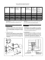
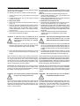
INSTRUCTION MANUAL NO. 268 CATALOG
BETRIEBSANLEITUNG NR. 268 KATALOG
STYLES
TYPEN
20600A
20600B
20600E
20600F
20600H
20600T
20600HD
20600TD
COLUMNS FOR BAG CLOSING UNITS
SÄULEN FÜR SACKZUNÄHANLAGEN
INSTRUCTION NO.
BETRIEBSANLEITUNG NR.
268 CATALOG
For Styles
Für die Typen
20600 A
20600 B
20600 E
20600 F
20600 H
20600 T
20600 HD
20600 TD
VORWORT
PREFACE
This instruction manual is designed to familiarize the user Diese Betriebsanleitung soll erleichtern, die Maschine/ Anlage kennenzulernen und ihre bestimmungsgemäßen
with the machine/ unit and its designated use.
Einsatzmöglichkeiten zu nutzen.
Die Betriebsanleitung enthält wichtige Hinweise, die Maschine/ Anlage sicher, sachgerecht und wirtschaftlich zu betreiben. Ihre Beachtung hilft, Gefahren zu vermeiden, Reparaturkosten und Ausfallzeiten zu vermindern und die Zuverlässigkeit und die Lebensdauer der Maschine/ Anlage zu erhöhen.
The instruction manual contains important information on
how to operate the machine/ unit safely, properly and most
efficiently. Observing these instructions helps to avoid danger, to reduce repair costs and downtimes and to increase
the reliability and life of the machine/ unit.
The instruction manual is to be supplemented by the re- Die Betriebsanleitung ist um Anweisungen aufgrund
spective national rules and regulations for accident preven- bestehender nationaler Vorschriften zur Unfallverhütung und
zum Umweltschutz zu ergänzen.
tion and environmental protection.
The instruction manual must always be available wherever Die Betriebsanleitung muß ständig am Einsatzort der Maschine/ Anlage verfügbar sein.
the machine/ unit is in use.
This instruction manual must be read and applied by any Die Betriebsanleitung ist von jeder Person zu lesen und anperson in charge of carrying out work with and on the zuwenden, die mit Arbeiten mit/ an der Maschine/ Anlage z.
B.
machine/ unit, such as
-
operation including setting up, troubleshooting in the
course of work and care.
-
Bedienung, einschließlich Rüsten, Störungsbehebung
im Arbeitsablauf und Pflege.
-
maintenance (servicing, inspection, repair) and/ or
-
Instandhaltung (Wartung, Inspektion, Instandsetzung)
und/ oder
-
transport.
-
Transport
beauftragt ist.
Neben der Betriebsanleitung und den im Verwenderland und
an der Einsatzstelle geltenden verbindlichen Regelungen zur
Unfallverhütung sind auch die anerkannten fachtechnischen
Regeln für sicherheits- und -fachgerechtes Arbeiten zu beachten.
In addition to the operating instructions and to the mandatory rules and regulations for accident prevention and environmental protection in the country and place of use of
the machine/ unit, the generally recognized technical rules
for safe and proper working must also be observed.
Subject to change without notice
Änderungen vorbehalten
268 CATALOG en/de
First edition/ Erste Auflage 2001-02-21
Printed in the Federal Republic of Germany © Union Special GmbH 2001
'
2
TABLE OF CONTENTS
INHALTSVERZEICHNIS
PAGE
SEITE
SAFETY RULES
SICHERHEITSHINWEISE
4-5
IDENTIFICATION OF COLUMNS
BEZEICHNUNG DER SÄULEN
5
APPLICATION OF THIS INSTRUCTION MANUAL
HINWEIS ZUR BENÜTZUNG DIESER BETRIEBSANLEITUNG
5
COLUMNS FOR BAG CLOSING UNITS
SÄULEN FÜR SACKZUNÄHANLAGEN
6-8
1. SINGLE HEAD TELESCOPIC COLUMNS FOR MOUNTING ONE BAG
CLOSING SEWING MACHINE, COLUMN STYLES
1. EINKOPF-TELESKOPSÄULEN ZUR AUFNAHME EINER SACKZUNÄHMASCHINE, SÄULENTYPEN
6-7
2. DOUBLE HEAD TELESCOPIC COLUMNS FOR MOUNTING TWO
BAG CLOSING SEWING MACHINES, COLUMN STYLES
2. DOPPELKOPF-TELESKOPSÄULEN ZUR AUFNAHME VON
ZWEI SACKZUNÄHMASCHINEN, SÄULENTYPEN
7-8
OPTIONAL FEATURES
ZUSATZAUSSTATTUNG
8-9
INSTALLATION
AUFSTELLUNG
10 - 11
PACKING
VERPACKUNG
10
PLACE OF OPERATION
AUFSTELLUNGSORT
10
MOUNTING SEWING MACHINE AND THREAD STAND
MONTAGE VON NÄHMASCHINE UND FADENSTÄNDER
11
CONNECTION ON THE MAINS SUPPLY
ANSCHLUSS AM STROMNETZ
12 - 13
CONNECTION OF AUTOMATIC SEWING MACHINES WITH ELECTROPNEUMATIC CUTTER DRIVE TO COMPRESSED AIR
ANSCHLUSS VON AUTOMATIK NÄHMASCHINEN MIT ELEKTROPNEUMATISCHEM ABSCHNEIDERANTRIEB AN DRUCKLUFT
14
INSTALLATION OF THE OPTIONAL FEATURES
INSTALLIEREN DER ZUSATZAUSSTATTUNG
14 - 15
CHECKING THE SENSE OF ROTATION
PRÜFEN DER DREHRICHTUNG
16
OPERATING INSTRUCTIONS
BEDIENUNGSANLEITUNG
17 - 20
HEIGHT ADJUSTMENT
HÖHENVERSTELLUNG
17
ARRANGEMENT OF SWITCHES AND PUSH BUTTONS
ANORDNUNG DER SCHALTER UND DRUCKTASTER
17
SWITCHING ON AND OFF THE VARIOUS COLUMN STYLES
EIN- UND AUSSCHALTEN DER VERSCHIEDENEN SÄULENTYPEN
17 - 20
OPERATING
BEDIENEN
19 - 20
TYPE OF CLOSURE/ DIMENSIONS
VERSCHLUSSART/ ABMESSUNGEN
21
SYNCHRONIZING THE SPEEDS OF SEWING MACHINE AND BAG
FEED-IN DEVICE WITH THE SPEED OF THE CONVEYOR
ANPASSUNG DER GESCHWINDIGKEITEN VON NÄHMASCHINE UND SACKZUFÜHREINRICHTUNG AN DIE GESCHWINDIGKEIT DES TRANSPORTBANDES
22 - 24
SETTING THE SEWING MACHINE SPEED
EINSTELLEN DER NÄHMASCHINENGESCHWINDIGKEIT
22 - 23
TENSIONING THE V-BELT
SPANNEN DES KEILRIEMENS
23
SETTING THE SPEED OF THE BAG FEED-IN DEVICE
EINSTELLEN DER GESCHWINDIGKEIT DER SACKZUFÜHREINRICHTUNG
24
FUNCTION TESTS
FUNKTIONSTESTS
24
3
SAFETY RULES
SICHERHEITSHINWEISE
The putting into service of the bag closing units is prohibited until it has been ascertained that the complete unit
including sewing machine(s) and optional features
(conveyor, bag feed-in device etc.) is conform with the
EC Council Directives Machinery.
Die Inbetriebnahme der Sackzunähanlagen ist solange untersagt bis festgestellt wurde, daß die gesamte Anlage, einschließlich Sackzunähmaschine(n) und wahlweiser
Zusatzausstattung (Transportband, Sackzuführeinrichtung
usw.) der EG-Maschinenrichtlinie entspricht.
1.
1.
Before putting the bag closing units into service carefully read the instructions.
The starting of each unit is only permitted after taking notice of the instructions and by qualified operators.
IMPORTANT!
Before putting into service also read the
safety rules and instructions of the
sewing machine, of the optional features and those of the motor supplier.
Lesen Sie vor Inbetriebnahme der Sackzunähanlagen die
Betriebsanleitung sorgfältig.
Jede Anlage darf erst nach Kenntnisnahme der Betriebsanleitung und nur durch entsprechend unterwiesene Bedienungspersonen betätigt werden.
WICHTIG! Lesen Sie vor Inbetriebnahme auch die Sicherheitshinweise und die Bedienungsanleitung
der Sackzunähmaschine, der Zusatzeinrichtung
und die des Motorenherstellers.
2.
Observe the national safety rules valid for your country.
2.
Beachten Sie die für Ihr Land geltenden nationalen Unfallverhütungsvorschriften.
3.
Each bag closing unit and sewing machine is only
allowed to be used as foreseen. The foreseen use
of the particular units and machines is described in
paragraph “COLUMNS FOR BAG CLOSING UNITS”
and in paragraph “STYLES OF MACHINES” of the
instruction manuals and in the text of the machine
offer. Another use, going beyond the description is
not as foreseen.
3.
Jede Sackzunähanlage und Sackzunähmaschine darf nur
ihrer Bestimmung gemäß verwendet werden. Der bestimmungsmäßige Gebrauch der einzelnen Anlagen und Maschinen ist im Abschnitt „SÄULEN FÜR SACKZUNÄHANLAGEN“ und im Abschnitt „MASCHINENTYPEN“ der Betriebsanleitungen und im Text des Maschinenangebots beschrieben. Eine andere, darüber hinausgehende Benutzung ist nicht bestimmungsgemäß.
4.
All safety devices must be in position when the bag
closing unit and the sewing machine are ready for
work or in operation. The operation without the appertaining safety devices is not allowed.
4.
Bei betriebsbereiter oder in Betrieb befindlicher Sackzunähanlage und Sackzunähmaschine müssen alle Schutzeinrichtungen montiert sein. Ohne zugehörige Schutzeinrichtungen ist der Betrieb nicht erlaubt.
5.
Wear safety glasses.
5.
Zu Ihrer persönlichen Sicherheit empfehlen wir zusätzlich
eine Schutzbrille zu tragen.
6.
In case of unit and machine conversions and
changes all relevant safety rules must be considered.
Conversions and changes are made by own risk.
6.
Umbauten und Veränderungen der Anlagen und Maschinen dürfen nur unter Beachtung aller einschlägigen Sicherheitsvorschriften vorgenommen werden. Umbauten und
Veränderungen erfolgen auf eigene Verantwortung.
7.
Warning hints in the instructions are marked with
the two shown symbols
7.
Warnhinweise sind in der Betriebsanleitung durch diese
beiden Symbole gekennzeichnet.
8.
For the following the unit has to be disconnected
from the power supply by turning off the main switch
or by pulling out the mains plug:
8.
Bei folgendem ist die Anlage durch Ausschalten am Hauptschalter oder durch Herausziehen des Netzsteckers vom
Netz zu trennen:
8.1 For threading needle(s), looper, etc.
8.1 Zum Einfädeln von Nadel(n), Greifer usw.
8.2 For inserting filler cord for sealing needle punctures
and for inserting binding tape.
8.2 Zum Einlegen von Dichtungskordel und Reiterband.
8.3 For replacing sewing tools such as needle, presser
foot, throat plate, looper, feed dog, needle guard,
binding tape folder, fabric guide, cutter knives etc.
8.3 Zum Auswechseln von Nähwerkzeugen wie Nadel,
Drückerfuß, Stichplatte, Greifer, Transporteur, Nadelanschlag, Reiterbandapparat, Stoff-Führung, Abschneidmessern usw.
8.4 For tightening and changing drive belts.
8.4 Zum Spannen oder Auswechseln von Antriebsriemen.
4
8.5 When leaving the working place and when the 8.5 Beim Verlassen des Arbeitsplatzes und bei unbeaufworking place is unattended.
sichtigtem Arbeitsplatz.
8.6 For maintenance work.
9.
8.6 Für Wartungsarbeiten.
Maintenance and repairs have to be done only by 9.
trained technicians or special skilled personnel
under consideration of the instructions. Only
genuine spare parts approved by UNION SPECIAL
have to be used for repairs.
Wartungs- und Reparaturarbeiten dürfen nur von Fachkräften oder entsprechend unterwiesenen Personen unter Beachtung der Betriebsanleitung durchgeführt werden. Für Reparaturen sind nur die von UNION SPECIAL
freigegebenen Original-Ersatzteile zu verwenden.
10. Any work on the electrical equipment has to be done 10. Arbeiten an der elektrischen Ausrüstung dürfen nur von
by electricians or under direction and supervision
Elektrofachkräften oder unter Leitung und Aufsicht von
of special skilled personnel.
entsprechend unterwiesenen Personen durchgeführt
werden.
11. Works on parts and equipment under electrical
tension are not permitted. Permissible exceptions 11. Arbeiten an unter Spannung stehenden Teilen und Einare described in the applicable section of standard
richtungen sind nicht erlaubt. Ausnahmen regeln die zusheet EN50110.
treffenden Teile der EN 50110.
12
Before making maintenance and repair works on 12. Vor Wartungs- und Reparaturarbeiten an pneumatithe pneumatic equipment the unit has to be disconschen Einrichtungen ist die Anlage vom pneumatischen
nected from the compressed air supply.
Versorgungsnetz zu trennen.
In case of existing residual air pressure after disconWenn nach der Trennung vom pneumatischen Versornecting from compressed air supply (e.g. pneumatic
gungsnetz noch Restenergie ansteht (z. B. bei
equipment with air tank), it has to be removed by
pneumatischen Einrichtungen mit Windkessel), ist diebleeding.
se durch Entlüften abzubauen.
Exceptions are only allowed for adjusting works and
Ausnahmen sind nur bei Einstellarbeiten und Funktifunction checks done by special skilled personnel.
onsprüfungen durch entsprechend unterwiesene
Fachkräfte zulässig.
Each UNION SPECIAL column for bag closing units is
dentified by a style number and a serial number.
Both numbers are stamped into the style plate affixed to
the column of the unit.
Jede UNION SPECIAL Säule für Sackzunähanlagen hat eine
Typennummer und eine Seriennummer.
Beide Nummern sind in das Typenschild, das an der Säule
der Anlage befestigt ist, eingeprägt.
NOTE: Instructions stating direction or location such as BEACHTEN SIE: Hinweise auf Richtung und Lage, wie
right left, front or rear of unit, are given relative
rechts, links, vorne oder hinten beziehen
to operator’s position at the unit, unless
sich auf die Sicht vom Platz der sich vor
otherwise noted.
der Anlage befindlichen Bedienungsperson
aus, wenn nicht anders angegeben.
CAUTION! Before putting into service check the ACHTUNG!
direction of rotation. Breakage may occur
when the direction of rotation is wrong.
Refer to paragraph “INSTALLATION” in this
instruction manual.
APPLICATION OF THIS INSTRUCTION MANUAL
Überprüfen Sie vor Inbetriebnahme die Drehrichtung. Bei falscher Drehrichtung kann Bruch
entstehen.
Siehe Abschnitt „AUFSTELLUNG“ in dieser
Be triebsanleitung.
HINWEIS ZUR BENÜTZUNG DIESER BETRIEBSANLEITUNG
Complete UNION SPECIAL bag closing units consist of
column and bag closing sewing machine as well as of
optional features (e.g. bag feed-in device, conveyor etc.)
Therefore use this instruction manual in conjunction with
the instruction manuals for the sewing machine(s), the
bag feed-in device etc. According to the delivery content,
these are added additionally to each complete unit.
Komplette UNION SPECIAL Sackzunähanlagen bestehen
aus Säule und Sackzunähmaschine sowie wahlweise möglicher Zusatzausstattung (z. B. Sackzuführeinrichtung, Transportband usw.).
Verwenden Sie deshalb diese Betriebsanleitung zusammen
mit den Betriebsanleitungen für die Nähmaschine(n), die
Sackzuführeinrichtung usw. Diese sind entsprechend dem
Lieferumfang zusätzlich jeder kompletten Anlage beigefügt.
Besides this to each complete bag closing unit is added Jeder kompletten Sackzunähanlage sind zudem das Datenthe data sheet for the motor(s) used, the diagrams for blatt für den (die) verwendeten Motor(e), die Pläne für die
the electrical equipment, dimensioned sketches of the elektrische Ausrüstung, Maßskizzen der Anlage und ein illuunit and an illustrated parts list for the column.
striertes Teileverzeichnis für die Säule beigefügt.
5
COLUMNS FOR BAG CLOSING UNITS
SÄULEN FÜR SACKZUNÄHANLAGEN
1. SINGLE HEAD TELESCOPIC COLUMNS FOR MOUN- 1. EINKOPF-TELESKOPSÄULEN ZUR AUFNAHME EINER
TING ONE BAG CLOSING SEWING MACHINE
SACKZUNÄHMASCHINE
Telescopic columns with base, flanged traverse with Teleskopsäulen mit Fuß, angeflanschter Traverse mit Nähmasewing machine bracket, thread stand and sewing schinenträger, Fadenständer und Nähmaschinenantriebsmomachine drive motor.
tor.
Sewing machine bracket with mounting plate for the
sewing machine. By loosening a T-screw the mounting
plate with sewing machine can be swung-out by approx.
75°. This allows easy access to the sewing machine for
threading, inspection and maintenance work. When
swinging-out the sewing machine the belt guard opens
automatically, providing access to the machine pulley for
easy manual positioning of needle and looper.
Nähmaschinenträger mit Aufnahmeplatte für die Nähmaschine.
Die Aufnahmeplatte mit Nähmaschine läßt sich nach Lösen
einer Knebelschraube um ca. 75° ausschwenken. Dies ermöglicht einen schnellen Zugang zur Nähmaschine, zum Einfädeln,
wie auch für Inspektions- und Wartungsarbeiten. Beim Ausschwenken der Nähmaschine öffnet sich der Riemenschutz
automatisch, die Handrad-Riemenscheibe wird zugänglich,
Nadel und Greifer können leicht von Hand positioniert werden.
On columns styles 20600 E, 20600 F, 20600 H and 20600
T a safety switch (protective system IP65) integrated in
the mounting plate prevents starting of the unit with sewing
machine in the swung-out position.
Bei den Säulentypen 20600 E, 20600 F, 20600 H und 20600 T
verhindert ein in die Aufnahmeplatte integrierter Sicherheitsschalter (Schutzart IP65), daß die Anlage mit Nähmaschine in
ausgeschwenktem Zustand eingeschaltet werden kann.
Thread stand for two cones of sewing thread weight up Fadenständer für zwei bis zu je 7,5 kg schwere Nähgarnrollen.
to 7,5 kg (approx. 16,5 lbs) each.
Nähmaschinenantriebsmotor. Abhängig vom Nähmaschinentyp
Sewing machine drive motor. Depending on style of und der Transportgeschwindigkeit sind die Säulen mit einem
sewing machine and the conveyor speed the columns Drehstrommotor oder Drehstrombremsmotor ausgestattet. Leiare equipped with a three phase A.C. motor or a three stung 0,37 kW, Schutzart IP54, Isolierstoffphase A.C. brake motor. Power 0,37 kW, protective klasse F.
system IP54, insulation class F.
Standardspannung 230/ 400 V, 50 Hz.
Standard voltage: 230/ 400V, 50 cycles.
Die im Durchmesser verstellbare Motorriemenscheibe mit
The variable pitch motor pulley facilitates synchronization Spannbuchse erleichtert das Synchronisieren von Näh- und
of sewing machine and conveyor speed.
Transportbandgeschwindigkeit.
Continuously variable sewing machine height adjustment:
On column styles 20600 A, 20600 B, 20600 E, 20600 F
and 20600 H manually by turning a handwheel, horizontally mounted at the upper end of the column.
On column style 20600 T electromotive by a push button
controlled electric motor, mounted at the upper end of
column, which is switched off automatically by proximity
switches when the highest or lowest position is reached.
Range of height adjustment: 780 to 1450 mm (670 mm)
from lower edge of column to the needle.
On single head telescopic columns this range can be
raised by approx. 100 mm and lowered by approx. 380
mm when relocating the complete traverse.
By locking a handle screw in the outer tube of columns
the set sewing machine height can be secured.
CAUTION: Before changing the sewing machine height
the handle screw has to be unlocked again.
Stufenlose Nähmaschinen-Höhenverstellung:
Bei den Säulentypen 20600 A, 20600 B, 20600 E, 20600 F und
20600 H von Hand, durch Drehen eines am oberen Ende der
Säule horizontal angebrachten Handrades.
Beim Säulentyp 20600 T elektromotorisch durch einen am oberen Ende der Säule angebauten, drucktaster-gesteuer-ten Elektromotor, der automatisch über Näherungsschalter abschaltet,
wenn der höchste oder tiefste Stand erreicht ist.
Höhenverstellbereich: 780 bis 1450 mm (670) mm von Unterkante Säule bis zur Nadel.
Bei Einkopf-Teleskopsäulen kann dieser Bereich, durch Versetzten der gesamten Traverse, um ca. 100 mm nach oben
und um ca. 380 mm nach unten verändert werden.
Durch Festziehen einer Griffschraube im Außenrohr der Säule
wird die eingestellte Nähmaschinenhöhe gesichert.
ACHTUNG: Vor dem Verändern der Nähmaschinenhöhe muß
die Griffschraube wieder gelöst werden!
On column styles 20600 E, 20600 F, 20600 H and 20600
T the switch box is mounted in front of the traverse and
meets the protective system requirements IP55. It
contains all necessary switching and protection elements.
The control circuit is protected by an isolation transformer.
The fuses in the switch box are fitted with indicator lamps,
making it easy to recognize any defective fuse when
opening the cover of the switch box and to change it.
Bei den Säulentypen 20600 E, 20600 F, 20600 H und 20600 T
ist der Schaltkasten nach vorne an der Traverse montiert. Er
entspricht der Schutzart IP55 und enthält alle notwendigen
Schalt- und Sicherungselemente. Das Steuerungsteil ist durch
einen Trenntransformator abgesichert. Die Sicherungen im
Schaltkasten sind mit einer Leuchtanzeige versehen. Dadurch
sind defekte Sicherungen sofort nach Öffnen des Schaltkastendeckels zu erkennen und auszutauschen.
6
The main switch is located in the switch box cover, as well
as a luminous button and mushroom button for switch on
and off the control within easy reach of the operator. On
column style 20600 T the two push buttons for the electromotive height adjustment are located additionally in the
switch box cover.
Im Handbereich der Bedienungsperson befinden sich im
Schaltkastendeckel der Hauptschalter sowie ein Leucht- und
ein Pilztaster zum Ein- und Ausschalten der Steuerung. Beim
Säulentyp 20600 T befinden sich die beiden Drucktaster für die
elektromotorische Höhenverstellung zusätzlich im Schaltkastendeckel.
COLUMN STYLES
SÄULENTYPEN
20600 A manual height adjustment with three phase A.C. 20600 A handhöhenverstellbar mit Drehstrommotor, ohne jegliche andere elektrische Ausstattung. Zum Einbau in Vermotor, but without any other electrical equipment. For
packungsanlagen oder zur Eigeninstallation. Bei entspreinstallation in packaging units or for own installation. With
chender Ausstattung geeignet für alle Nähmaschinen Klasse
corresponding equipment suitable for all sewing
80800.
machines class 80800.
Gewicht: 122 kg
Weight: 122 kg
20600 B manual height adjustment with simplified electrical 20600 B handhöhenverstellbar mit vereinfachter elektrischer
Ausstattung, ohne Schaltkasten. Ausgestattet mit Drehequipment, without switch box. Equipped with threestrommotor, Motorschutzschalter und Fußschalter zur Aufphase A.C. motor, motor protection switch and foot switch
nahme einer Standard-Nähmaschine Typ 80800 C, D, H oder
for mounting a standard sewing machine style 80800 C,
HA.
D, H or HA.
Gewicht: 130 kg
Weight 130 kg
20600 E manual height adjustment with switch box and 20600 E handhöhenverstellbar mit Schaltkasten und kompletter elektrischer Ausstattung, nach EN 60204-1 (VDE 0113),
complete electrical equipment according to EN 60204-1
Standard Schutzart IP54. Mit Drehstrommotor zur Aufnahme
(VDE 0113), standard protective system IP54. With three
einer Standard-Nähmaschine Typ 80800 C, D, H oder HA,
phase A.C. motor for mounting a standard sewing
einschließlich Fußschalter zur Ansteuerung der Nähmaschimachine style 80800 C, D, H or HA including foot switch
ne.
for operating the sewing machine.
Gewicht: 140 kg
Weight: 140 kg
20600 F manual height adjustment with switch box and 20600 F handhöhenverstellbar mit Schaltkasten und kompletter elektrischer Ausstattung, nach EN 60204-1 (VDE 0113),
complete electrical equipment according to EN 60204-1
Standard Schutzart IP54. Mit Drehstrommotor zur Aufnahme
(VDE 0113), standard protective system IP54. With three
einer Automatik-Nähmaschine Typ 80800 R, RL, S, SL oder
phase A.C. motor for mounting an automatic sewing
mit Drehstrombremsmotor zur Aufnahme einer Automatikmachine style 80800 R, RL, S, SL or with three phase
Nähmaschine Typ 80800 TL, U, UL.
A.C. brake motor for mounting an automatic sewing
Gewicht: 140 kg
machine style 80800 TL, U, UL
Weight: 140 kg
20600 H manual height adjustment with switch box and 20600 H handhöhenverstellbar mit Schaltkasten und kompletter elektrischer Ausstattung nach EN 60204-1 (VDE 0113),
complete electrical equipment, according to EN 60204Standard Schutzart IP54. Mit Drehstrommotor zur Aufnahme
1 (VDE 0113), standard protective system IP54. With
einer Automatik-Nähmaschine Typ 80800 R, RL, S, SL, oder
three phase A.C. motor for mounting an automatic sewing
mit Drehstrombremsmotor zur Aufnahme einer Automatikmachine style 80800 R, RL, S, SL or with three phase
Nähmaschine Type 80800 TL, UA und UAL und einer
A.C. brake motor for mounting an automatic sewing
Sackzuführeinrichtung GA 29905, GA 29910 oder GA 29915.
machine style 80800 TL, UA, and UAL and a bag feedGewicht: 140 kg.
in-device GA 29905, GA 29910 or GA 29915.
Weight: 140 kg
20600 T electromotive height adjustment with switch box 20600 T elektromotorisch höhenverstellbar mit Schaltkasten und
and complete electrical equipment according to EN
kompletter elektrischer Ausstattung, nach EN 60204-1 (VDE
60204-1 (VDE 0113), standard protective system IP54.
0113), Standard Schutzart IP54. Mit Drehstrommotor zur AufWith three phase A.C. motor for mounting an automatic
nahme einer Automatik-Nähmaschine Typ 80800 R, RL, S,
sewing machine style 80800 R, RL, S, SL or with three
SL, oder mit Drehstrombremsmotor zur Aufnahme einer Auphase A.C. brake motor for mounting an automatic
tomatik-Nähmaschine 80800 TL, U, UA, UL, UAL. Bei Bedarf
sewing machine style 80800 TL, U, UA, UL, UAL. If requimit Steckdose im Schaltkasten zum Anschluß einer
red with socket in switch box for connecting a bag feedSackzuführeinrichtung.
in-device.
Gewicht: 145 kg
Weight: 145 kg
2. DOUBLE HEAD TELESCOPIC COLUMNS FOR MOUN- 2. DOPPELKOPF-TELESKOPSÄULEN ZUR AUFNAHME
TING TWO BAG CLOSING SEWING MACHINES
VON ZWEI SACKZUNÄHMASCHINEN
Telescopic columns with base, carrying flange with two traverses with sewing machine brackets, thread stands and
sewing machine drive motors. After unlocking a retention
pin the carrying flange can be turned by 180°.
Teleskopsäulen mit Fuß, Tragflansch mit zwei Traversen mit
Nähmaschinenträgern, Fadenständern und Nähmaschinenantriebsmotoren. Nach Entriegeln eines Arretierstiftes läßt sich
der Tragflansch um 180° schwenken.
For mounting two bag closing sewing machines of the same
style. Turning the second sewing machine into position
avoids production interruptions when changing thread or
needle,
Zur Aufnahme von zwei gleichen Sackzunähmaschinen. Durch
Einschwenken der zweiten Nähmaschine können bei Fadenoder Nadelwechsel Produktionsunterbrechungen vermieden
werden
7
or
for mounting two different bag closing sewing machines
for various types of closure. Turning the second sewing
machine into position allows quick change from one type
of closure to the other.
oder
zur Aufnahme von zwei verschiedenen Sackzunähmaschinen für unterschiedliche Verschlußarten. Durch Einschwenken der zweiten Nähmaschine kann schnell von einer Verschlußart zur anderen gewechselt werden.
Sewing machine brackets with integrated safety switch in
the mounting plate, thread stands, sewing machine drive
motors, motor pulleys, sewing machine height adjustment
and switch box are as described for the single head telescopic columns.
Nähmaschinenträger mit in die Aufnahmeplatte integriertem
Sicherheitsschalter,Fadenständer, Nähmaschinenantriebsmotor,Motorriemenscheiben,Nähmaschinenhöhenverstellung und Schaltkasten sind entsprechend wie bei den Einkopf-Teleskopsäulen beschrieben.
On double head telescopic columns the switch box is
mounted on the column between the sewing machines.
All necessary switches and push buttons (protective
system IP65) are located on a console within easy reach
of the operator.
Bei Doppelkopf-Teleskopsäulen ist der Schaltkasten an der
Säule zwischen den Nähmaschinen montiert. Alle erforderlichen Schalter und Taster (Schutzart IP 65) befinden sich an
einer Konsole im Handbereich der Bedienungsperson.
COLUMN STYLES
SÄULENTYPEN
20600 HD manual height adjustment, with switch box and 20600 HD handhöhenverstellbar, mit Schaltkasten und komcomplete electrical equipment according to EN 60204pletter elektrischer Ausstattung, nach EN 60204-1 (VDE
1 (VDE 0113), standard protective system IP54. With
0113), Standard Schutzart IP54. Mit Drehstrommotoren zur
three phase A.C. motors for mounting two automatic
Aufnahme von zwei Automatik-Nähmaschinen Typ 80800
sewing machines style 80800 R, RL, S, SL or with three
R, RL, S, SL oder mit Drehstrombremsmotoren zur Aufnahphase A.C. brake motors for mounting two automatic
me von zwei Automatik-Nähmaschinen Typ 80800 TL, U,
sewing machines style 80800 TL, U, UA, UL, UAL. If
UA, UL, UAL. Bei Bedarf mit Steckdosen im Schaltkasten
required with sockets in switch box for connecting bag
zum Anschluß von Sackzuführeinrichtungen.
feed-in devices.
Gewicht: 190 kg
Weight: 190 kg
20600 TD electromotive height adjustment with switch box 20600 TD elektromotorisch höhenverstellbar mit Schaltkasand complete electrical equipment according to EN
ten und kompletter elektrischer Ausstattung, nach EN 6020460204-1 (VDE 0113) standard protective system IP54.
1 (VDE 0113), Standard Schutzart IP54. Mit DrehstrommoWith three phase A.C. motors for mounting two
toren zur Aufnahme von zwei Automatik-Nähmaschinen Typ
automatic sewing machines style 80800 R, RL, S, SL
80800 R, RL, S, SL oder mit Drehstrombremsmotoren zur
or with three phase A.C. brake motors for mounting two
Aufnahme von zwei Automatik-Nähmaschinen Typ 80800
automatic sewing machines style 80800 TL, U, UA, UL,
TL, U, UA, UL, UAL. Bei Bedarf mit Steckdosen im SchaltUAL. If required with sockets in switch box for connecting
kasten zum Anschluß von Sackzuführeinrichtungen.
bag feed-in devices.
Gewicht: 200 kg
Weight: 200 kg
HINWEIS: Die Säulentypen 20600 T, 20600 HD und 20600
HINT: Column styles 20600 T, 20600 HD and 20600 TD TD werden bei Bedarf auch vorbereitet zur Aufnahme von
are available on demand prepared for mounting standard Standard-Nähmaschinen Typ 80800 C, D, H oder HA geliesewing machines style 80800 C, D, H or HA, with foot fert, mit Fußschalter zur Nähmaschinensteuerung.
switch for sewing machine control.
OPTIONAL FEATURES *
ZUSATZAUSSTATTUNG *
20401 M heavy stationary base with only 70 mm (2 3/4 20401 M Schwerer Ständerfuß mit nur 70 mm hohen Seitenin.) high legs which can be placed under a conveyor.
teilen die unter ein Transportband geschoben werden könFor stable installation of the columns without fastening
nen. Zum standsicheren Aufstellen der Teleskopsäulen ohthe base to the floor.
ne Verankerung im Fußboden.
20401 F Movable base, lockable, with two rollers and two 20401 F Fahrbarer Ständerfuß, feststellbar, mit zwei Lenkguide rollers. This movable base makes the telescopic
und zwei Bockrollen. Mit diesem fahrbaren Ständerfuß wird
column with sewing machine(s) to a movable unit which
die Teleskopsäule mit Nähmaschine(n) zu einer fahrbaren
can be used at different locations.
Einheit, die an verschiedenen Orten eingesetzt werden
Measurements: 900 x 1050 mm (35 1/2 x 41 1/4 in.)
kann.
Height of base section extending under the conveyor is
Abmessungen: 900 x 1050 mm. Höhe des unter das Transonly 130 mm (5 in.).
portband reichenden Teils 130 mm.
GA 29905 Bag feed-in device for use in connection with GA 29905 Sackzuführeinrichtung zur Verwendung mit Autoautomatic sewing machines style 80800 R, RL, S and
matik-Nähmaschinen Typ 80800 R, RL, S und SL an den
SL on columns style 20600 H, T, HD or TD.
Teleskopsäulen Typ 20600 H, T, HD oder TD.
* Extra order and charge items.
* Gegen Extrabestellung und -berechnung
8
GA 29910 Bag feed-in and trimming device for use in con- GA 29910 Sackzuführ- und Beschneideeinrichtung zur Vernection with automatic sewing machines style 80800 TL,
wendung mit Automatik-Nähmaschinen Typ 80800 TL, UA
UA and UAL on columns style 20600 H, T, HD or TD.
und UAL an den Teleskopsäulen Typ 20600 H, T, HD oder
TD.
GA 29915 Bag feed-in, trimming and fold down device for
use in connection with automatic sewing machines style GA 29915 Sackzuführ-, Beschneide- und Umfalteinrichtung
80800 R, RL, S and SL on columns style 20600 H, T, HD
für Automatik-Nähmaschinen Typ 80800 R, RL, S und SL
or TD.
an den Teleskopsäulen Typ 20600 H, T, HD oder TD.
29916 PP Pressure reducing valve parts kit, required when 29916 PP Druckminderer-Teilesatz, notwendig bei Verwenusing automatic sewing machines style 80800 RL, SL,
dung von Automatik-Nähmaschinen Typ 80800 RL, SL, TL,
TL, UL and UAL with electropneumatic cutter. Mounted
UL und UAL mit elektropneumatischem Abschneider. An der
to the back of the traverse.
Rückseite der Traverse montiert.
Pressure reducing valve with pressure gauge, 0,5 to 6
Druckminderer mit Manometer 0,5 - 6 bar, Durchfluß linksbar (approx. 7 to 87 psi) flow direction left-right, barbed
rechts, Schlauchtülle R 1/8 und 3 m PVC-Gewebeschlauch
fitting R 1/8 with 3 meter fabric reinforced PVC-tubing 6 x
6 x 3 für Druckluftanschluß.
3 for compressed air connection.
Für Doppelkopf-Teleskopsäulen wird zusätzlich eine T-VerOn double head telescopic columns a swivel Tee part
schraubung, Teil-Nr. 999-163 B zum Anschluß der zweiten
No. 999-163 B is additionally required for connecting the
Nähmaschine benötigt.
second sewing machine.
29926 BA Electro parts-kit for additionally cutting the bin- 29926 BA Elektro-Teilesatz für zusätzliches Schneiden des
ding tape at the start of seam. For installation in switch
Reiterbandes am Nahtanfang. Zum Einbau in Schaltkästen
boxes of column styles 20600 F, H, T, HD and TD which
der Teleskopsäulen Typ 20600 F, H, T, HD und TD die mit
are equipped with automatic sewing machines style
Automatik-Nähmaschinen Typ 80800 TL, U, UA, UL oder
80800 TL, U, UA, UL or UAL for binding tape closure.
UAL für Reiterband-Verschluß ausgerüstet sind.
29926 C Foot switch with electroparts-kit for controlling a 29926 C Fußschalter mit Elektro-Teilesatz, zur Steuerung eiconveyor on column styles 20600 E, F, H, T, HD and TD.
nes Transportbandes für die Teleskopsäulen Typ 20600 E,
F, H, T, HD und TD.
91605 G Belt type conveyor with gear motor.
91605 G Gurttransportband mit Getriebemotor.
91605 L Slat type conveyor with gear motor.
91605 L Lattentransportband mit Getriebemotor.
93051 F Fold-down device for the bag top, for use with bag 93051 F Umfalteinrichtung für die Sackoberkante, zur Verfeed-in device No. GA 29905.
wendung mit der Sackzuführeinrichtung Nr. GA 29905.
93065 BF Supplementary thread stand parts for one cone 93065 BF Fadenständer-Zusatzteile zur Aufnahme einer Rolof filler cord. On double head telescopic columns two part
le Dichtungskordel. Für Doppelkopf-Teleskopsäulen werden
kits are required.
zwei Teilesätze benötigt.
998A28A Thread break detector for controlling two threads. 998A28A Fadenwächter zum Überwachen von zwei Fäden.
For use on columns style 20600 E, F, H, T, HD and TD.
Zur Verwendung an den Teleskopsäulen Typ 20600 E, F, H,
T, HD und TD.
HINT: For detailed information each optional feature comes, HINWEIS: Zur näheren Information enthält, soweit notwenas far as necessary, with an appertaining instruction.
dig, jede Zusatzausstattung eine entsprechende Betriebsanleitung.
9
AUFSTELLUNG
INSTALLATION
PACKING
VERPACKUNG
The columns are delivered on a throw-away pallet. Remove the wrapping and take the sewing machine(s),
packed in separate carton(s) from the pallet, also the
optional feature (e.g. bag feed-in device), packed in
a separate carton.
Die Säulen werden auf einer Einweg-Palette geliefert. Entfernen Sie die Verpackung und nehmen Sie die in separaten
Karton verpackte(n) Nähmaschine(n) von der Palette. Ebenso die in separatem Karton verpackte Zusatzausstattung (z.
B. Sackzuführungeinrichtung).
CAUTION: COLUMNS WITHOUT HEAVY STATIONARY ACHTUNG!
BASE No. 20401 M respectively MOVEABLE
BASE No. 20401F (optional) SHOULD NOT
BE LOOSENED FROM THE PALLET IN ANY
CASE BEFORE THE PLACE OF OPERATION
OF THE COLUMN IS READILY PREPARED
FOR FASTENING!
PLACE OF OPERATION
SÄULEN OHNE SCHWEREN STÄNDERFUSS
Nr. 20401 M bzw. FAHRBAREN STÄNDERFUSS Nr. 20401 F (Zusatzausstattungen) DÜRFEN AUF KEINEN FALL VON DER PALETTE
GELÖST WERDEN BEVOR DER ORT, AN
DEM DIE SÄULE AUFGESTELLT WERDEN
SOLL, ZUM BEFESTIGEN FERTIG VORBEREITET IST!
AUFSTELLUNGSORT
The space required is shown in the dimensioned sketch Den erforderlichen Raum- und Platzbedarf entnehmen Sie
coming with each column.
bitte der jeder Säule beigefügten Maßskizze.
Columns without heavy stationary base respectively moveable base are fastened with four screws or bolts to
the floor, see Fig. 1. The four holes (16 mm = 5/8 in.
dia.) in the base plate on the inner tube of the column
are designed for mounting parts with M 12 thread.
Säulen ohne schweren Ständerfuß bzw. fahrbaren Ständerfuß werden mit vier Schrauben oder Bolzen im Fundament
verankert, siehe Fig. 1. Die vier Durchgangsbohrungen (Ø16
mm) in der Grundplatte am Innenrohr der Säule sind für
Befestigungselemente mit M 12 Gewinde ausgelegt.
Mounting parts (e.g. M 12 thread screws with heavy load
dowels or M 12 thread stone bolts with washers and
nuts) are no components of the column. Kind, design
and length of the mounting parts conform to the
condition of the floor and have to be determined by
an expert on the spot.
Befestigungselemente (z. B. M 12 Gewindeschrauben mit
Schwerlastdübeln oder M 12 Gewinde-Steinschrauben mit
Scheiben und Muttern) gehören nicht zum Lieferumfang der
Säule. Art, Ausführung und Länge der Befestigungselemente
richtet sich nach der Beschaffenheit des Bodens/ Fundamentes und sind vor Ort von einem Fachmann zu bestimmen.
Fig. 1
Fig. 2
10
When the place of operation of the column with the
mounting parts is readily prepared, secure the column
against overturning by hanging it on a suitable hoisting
device (e.g. pulley block, crane etc.).
Note the center of mass of the column (S, Fig. 2) to avoid
overturning when lifting.
Now loosen the four screws securing the column on the
pallet and carry the column with the hoisting device to the
readily prepared place of operation. Fasten the column
carefully.
Wenn der Aufstellungsort der Säule mit den Befestigungselementen fertig vorbereitet ist, sichern Sie die Säule gegen
Umkippen durch Einhängen an einem geeigneten Hebezeug
(z. B. Flaschenzug, Kran usw.). Beachten Sie beim Einhängen den Schwerpunkt der Säule (S. Fig. 2), damit diese beim
Hochheben nicht kippt.
Lösen Sie nun die vier Schrauben mit denen die Säule auf
der Palette befestigt ist und bringen Sie mit Hilfe des Hebezeuges die Säule an den vorbereiteten Aufstellungsort. Befestigen Sie die Säule sorgfältig.
Columns with heavy stationary base respectively moveable
base can be taken with the hoisting device directly from
the pallet after loosening the fastening, and positioned
respectively rolled to the place of operation.
Columns with moveable base are secured against rolling
away from the place of operation by turning down the two
locking spindles.
Säulen mit schwerem Ständerfuß bzw. fahrbarem Ständerfuß können nach dem Lösen der Befestigung mit dem Hebezeug direkt von der Palette gehoben und an den Aufstellungsort gesetzt bzw. gerollt werden.
Säulen mit fahrbarem Ständerfuß werden am Aufstellungsort
durch Herunterdrehen der beiden Feststellspindeln gegen
Wegrollen gesichert.
MOUNTING SEWING MACHINE AND THREAD STAND
MONTAGE VON NÄHMASCHINE UND FADENSTÄNDER
Loosen cap nut (A, Fig. 3) and remove the belt guard cover
(B).
Loosen screw (C) for connecting rod (D) and tommy nut
(E) on the hinged mounting plate (F).
Unhinge mounting plate (F).
Lösen Sie die Hutmutter (A, Fig. 3) und entfernen Sie den
Riemenschutzdeckel (B).
Lösen Sie die Schraube (C) für die Verbindungsstange (D)
und die Knebelmutter (E) an der schwenkbaren Aufnahmeplatte (F).
Hängen Sie die Aufnahmeplatte (F) aus.
Unpack the sewing machine.
Packen Sie die Nähmaschine aus.
Attach the sewing machine with three machine fastening
screws (G. Fig. 4) and three locking rings (H) on the hinged
mounting plate (F). Hang the mounting plate with the
attached sewing machine back on its hinges.
Montieren Sie die Nähmaschine mit drei Maschinenbefestigungsschrauben (G, Fig. 4) und drei Federringen (H) an die
schwenkbare Aufnahmeplatte (F).
Hängen Sie die Aufnahmeplatte mit der montierten Nähmaschine wieder in die beiden Scharnierbolzen ein.
Mount the needle bar guard and the sight feed oiler to the
sewing machine, refer to paragraph “LUBRICATION AND
OPERATION” in the instructions for the sewing machine!
Oil the sewing machine as described.
Montieren Sie den Nadelstangenschutz und den Tropföler
an die Nähmaschine, siehe Abschnitt „SCHMIERUNG UND
INBETRIEBNAHME“ in der Betriebsanleitung für die Nähmaschine! Ölen Sie die Nähmaschine wie beschrieben.
Fig. 4
Fig. 3
11
Take the components of the thread stand from the accessories and assemble it as shown in Fig. 5. Choose the distance
between spool pin (S) and thread guide (T) according to
the size of the used cones of sewing thread.
Place the thread cones onto the spool pins and thread the
sewing machine, refer to paragraph “THREADING” in the
instructions for the sewing machine!
Nehmen Sie die Einzelteile für den Fadenständer aus dem
Zubehör und montieren Sie diesen wie in Fig. 5 gezeigt.
Wählen Sie den Abstand zwischen Spulenstift (S) und Fadenführung (T) entsprechend der Größe der verwendeten
Garnrollen.
Setzen Sie die Garnrollen auf die Spulenstifte und fädeln Sie
die Nähmaschine ein, siehe Abschnitt „EINFÄDELN“ in der
Betriebsanleitung für die Nähmaschine!
Place the V-belt coming with the column around the sewing
machine pulley and the motor pulley.
Hint: On columns which are delivered with sewing machine(s) the correct belt tension is set at the factory. If it would
become necessary to tension the belt, refer to paragraph
“TENSIONING THE V-BELT”.
Legen Sie den der Säule beigefügten Keilriemen um die Handrad-Riemenscheibe der Nähmaschine und die Motor-Keilriemenscheibe.
Hinweis: Bei Säulen die mit Nähmaschine(n) geliefert werden, ist die korrekte Riemenspannung ab Werk eingestellt.
Wenn es notwendig sein sollte den Keilriemen zu spannen,
siehe Abschnitt „SPANNEN DES KEILRIEMENS“.
Now push back the hinged mounting plate (F, Fig. 3) with
the attached sewing machine and lock it with tommy nut
(E). Refasten connecting rod (D) with screw (C) on mounting plate (F). Remount belt guard cover (B) and secure it
with cap nut (A).
Drücken Sie nun die schwenkbare Aufnahmeplatte (F, Fig. 3)
mit der Nähmaschine nach hinten und ziehen Sie diese mit
der Knebelmutter (E) fest. Befestigen Sie die Verbindungsstange (D) mit der Schraube (C) wieder an der Aufnahmeplatte (F). Setzen Sie den Riemenschutzdeckel (B) ein und
befestigen Sie ihn mit der Hutmutter (A).
CONNECTION TO THE MAINS SUPPLY
ANSCHLUSS AM STROMNETZ
CAUTION! Electrical connections are only allowed
to be done by skilled electricians!
ACHTUNG! Elektrische Anschlüsse dürfen nur von e i ner Elektro-Fachkraft durchgeführt werden!
Lead-in cable and mains plug are not furnished with the
column!
Except column style 20600 A each column comes with a
connecting diagram.
Zuleitungskabel und Netzstecker gehören nicht zum Lieferumfang der Säule!
Außer dem Säulentyp 20600 A ist jeder Säule ein Anschlußplan beifügt.
20600 A
Connection according to the user’s own
electrical installation.
20600 A
Anschluß entsprechend der vom Verwender
selbst installierten Elektrik.
20600 B
Connection according to the connecting
diagram coming with the column.
20600 B
Anschluß entsprechend dem der Säule
beiliegenden Anschlußplan.
20600 E
20600 F
20600 H
20600 T
20600 HD
20600 TD
Connection according to Fig. 6 in the switch
box on lower terminal strip.
20600 E
Anschluß entsprechend Fig. 6 im Schaltkasten
20600 F
auf der unteren Klemmenschiene.
20600 H
20600 T
20600 HD
20600 TD
12
TOTAL CONNECTED WATTAGE (Standard) *
GESAMTANSCHLUSSWERTE (Standard) *
Column
Säule
Connected
wattage
Anschlußwert
with bag feed- with conveyor
mit Transportin device
mit Sackzuführ- band
einrichtung
20600 A
20600 B
20600 E
20600 F
20600 H
20600 T
20600 HD
20600 TD
0,37 kW
0,37 kW
1,0 kW
1,0 kW
1,1 kW
1,65 kW
1,50 kW
2,4 kW
1,22
1,77
1,62
2,52
kW
kW
kW
kW
0,92 kW
1,55 kW
1,55 kW
1,65 kW
2,2 kW
2,05 kW
2,95 kW
with 2 bag feedin devices
mit 2 Sackzuführeinrichtungen
1,75 kW
2,75 kW
with bag feed-in
device and
conveyor
mit Sackzuführeinrichtung und
Transportband
1,77
2,32
2,17
3,07
with 2 bag feedin devices and
conveyor
mit 2 Sackzuführeinrichtungen und
Transportband
-
kW
kW
kW
kW
2,3 kW
3,2 kW
* The total connected wattage of a column may deviate
from standard.
The total connected wattage of each particular column
will be found on the inside of the switch box cover.
* Der Gesamtanschlußwert einer Säule kann vom Standard
abweichen.
Den Gesamtanschlußwert jeder einzelnen Säule finden
Sie auf der Innenseite des Schaltkastendeckels.
CONNECTION OF AUTOMATIC-SEWING MACHINES
TO THE SWITCH BOX
ANSCHLUSS VON AUTOMATIK-NÄHMASCHINEN AM
SCHALTKASTEN
1. Einkopfsäulen
1. Single head columns.
Schrauben Sie von der im Schaltplan mit „X1“ bezeichUnscrew the captive protection cap from socket on the
neten Steckdose auf der Unterseite des Schaltkastens
underside of the switch box, the socket is indicated with
die unverlierbare Verschlußkappe ab und stecken Sie den
“X1” on the wiring diagram. Insert the plug of the cutter
Stecker des Abschneider-Antriebs der Nähmaschine ein
drive of the sewing machine and tighten the coupling
und ziehen Sie die Überwurfmuttern an.
ring.
2. Doppelkopfsäulen
2. Double head columns
Schrauben Sie von den im Schaltplan „X1“ und „X2“ beUnscrew the captive protection caps from sockets on
zeichneten Steckdosen auf der Oberseite des Schaltkathe upper side of the switch box, the sockets are indicated
stens die unverlierbaren Verschlußkappen ab und stekwith “X1” and “X2” on the wiring diagram. Insert the plugs
ken Sie die Stecker des Abschneider-Antriebs der 1. und
of the cutter drive of the first and second sewing machine
2. Nähmaschine entsprechend in die Steckdosen „X1“
accordingly in sockets “X1” and “X2” and tighten the
und „X2“ ein und ziehen Sie die Überwurfmuttern an.
coupling rings.
Fig. 5
13
Fig. 6
CONNECTION OF AUTOMATIC-SEWING MACHINES ANSCHLUSS VON AUTOMATIK-NÄHMASCHINEN MIT
WITH ELECTROPNEUMATIC CUTTER DRIVE TO COM- ELEKTROPNEUMATISCHEM ABSCHNEIDERANTRIEB AN
PRESSED AIR
DRUCKLUFT
Screw the quick push-pull connector coming with the sewing
machine into the pressure reducing valve on the back of
the traverse and insert the free end of the PA-tube
connected on the sewing machine into the push-pull
connector.
On double head columns a swivel Tee is screwed into the
pressure reducing valve in which the two push-pull connectors of the sewing machines are screwed in.
Slip the fabric reinforced PVC-tubing, coming with the column, on the hose nozzle of the pressure reducing valve
and secure it with the tube clamp. Connect the free end of
the reinforced PVC-tubing to the compressed air supply.
Regulate the air pressure to 3 to 4 bar (43,5 to 58 psi).
Schrauben Sie die mit der Nähmaschine gelieferte Steckkupplung am Druckminderer an der Rückseite der Traverse ein und
stecken Sie das freie Ende des an der Nähmaschine angeschlossenen PA-Schlauches in die Steckkupplung ein.
Bei Doppelkopfsäulen wird eine T-Schwenkverschraubung am
Druckminderer eingeschraubt, in die die beiden Steckkupplungen der Nähmaschinen geschraubt werden.
Schieben Sie den mitgelieferten PVC-Gewebeschlauch über
die Schlauchtülle des Druckminderers und befestigen Sie ihn
mit der Schlauchklemme. Schließen Sie das andere Ende des
PVC-Gewebeschlauches am Druckluftnetz an.
Regeln Sie den Luftdruck auf 3 bis 4 bar.
INSTALLATION OF THE OPTIONAL FEATURES
INSTALLIEREN DER ZUSATZAUSSTATTUNG
1. Bag feed-in devices (columns 20600 H, T, HD, TD)
Attach the bag feed-in device(s) to the column as described
in instruction manual No. 270 A CATALOG and connect it
(them) to the switch box of the column.
1. Sackzuführeinrichtungen (Säulen 20600 H, T, HD, TD)
Montieren Sie die Sackzuführeinrichtung(en) an die Säule wie
in der Betriebsanleitung Nr. 270 A CATALOG beschrieben und
schließen Sie diese am Schaltkasten der Säule an.
1.1 Single head columns 20600 H and T
The sockets for connection are located on the underside
of the switch box and indicated with “X2” and “X5” on the
wiring diagram. Unscrew the captive protection cap from
socket “X2” and insert the plug of the pre-feeler of the bag
feed-in device, tighten the coupling ring.
1.1 Einkopfsäulen 20600 H und T
Die Steckdosen zum Anschluß befinden sich an der Unterseite
des Schaltkastens und sind im Schaltplan mit „X2“ und „X5“
bezeichnet. Schrauben Sie die unverlierbare Verschlußkappe
an der Steckdose „X2“ ab und stecken Sie den Stecker des
Vortasters der Sackzuführeinrichtung ein, ziehen Sie die Überwurfmutter an.
Open the flap of socket “X5” and insert the plug of the gear Öffnen Sie die Klappe der Steckdose „X5“ und stecken Sie den
motor cable of the bag feed-in device with a slight twist to Stecker des Getriebemotorkabels der Sackzuführeinrichtung, mit
the left.
einer leichten Drehung nach links, ein.
1.2 Double head columns 20600 HD and TD
The sockets for connection are located on the upper side
of the switch box and indicated on the wiring diagram with
“X3” and “X5” for the first sewing machine and with “X4”
and “X6” for the second sewing machine.
Connect to sockets “X3” and “X4” the pre-feelers of the
bag feed-in devices and to sockets “X5” and “X6” the plugs
of the gear motor cables of the bag feed-in devices as
described in item 1.1.
1.2 Doppelkopfsäulen 20600 HD und TD
Die Steckdosen zum Anschluß befinden sich an der Oberseite
des Schaltkastens und sind im Schaltplan mit „X3“ und „X5“ für
die erste Nähmaschine und mit „X4“ und „X6“ für die zweite
Nähmaschine bezeichnet.
Schließen Sie an den Steckdosen „X3“ und „X4“ die Vortaster
der Sackzuführeinrichtungen und an den Steckdosen „X5“ und
„X6“ die Stecker der Getriebemotorkabel der Sackzuführeinrichtungen an, wie in Punkt 1.1. beschrieben.
2. Conveyors
Conveyors on single head columns are installed as shown
in Fig. 7 A. Conveyors on double head columns are installed as shown in Fig. 7 B.
The guiding dimension (675 mm = 26 5/8 in.), shown in
Figs. 7 A and B, depends on the width of the bag to be
closed. The bag must remain upright on the conveyor until
the thread chain respectively binding tape with thread chain
is securely cut.
Connect the conveyor motor to the cable coming from the
switch box of the column.
2. Transportbänder
Transportbänder an Einkopfsäulen werden, wie in Fig. 7 A gezeigt, aufgestellt. Transportbänder an Doppelkopfsäulen werden, wie in Fig. 7 B gezeigt, aufgestellt.
Das in Fig. 7 A und 7 B gezeigte Richtmaß (675 mm) ist abhängig von der Breite des zu verschließenden Sackes. Der Sack
muß solange aufrecht auf dem Transportband bleiben, bis
Fadenkette bzw. Reiterband mit Fadenkette sicher abgeschnitten ist.
Schließen Sie den Transportband-Motor am Kabel des Schaltkastens der Säule an.
CAUTION: The connection of the conveyor motor is ACHTUNG: Der Anschluß des Tansportband-Motors darf
only allowed to be done by a skilled
nur von einer Elektro-Fachkraft durchgeführt
electrician!
werden!
14
15
CHECKING THE SENSE OF ROTATION
PRÜFEN DER DREHRICHTUNG
The sense of rotation of the motor pulley and of the sewing Die Drehrichtung der Motor-Keilriemenscheibe und der
machine pulley is clockwise.
Handrad-Riemenscheibe der Nähmaschine ist im UhrzeiFor checking the sense of rotation proceed as follows:
gersinn.
Gehen Sie zum Prüfen der Drehrichtung wie folgt vor:
1. Loosen cap nut (A, Fig. 3) and remove the belt guard 1. Lösen Sie die Hutmutter (A, Fig. 3) und entfernen Sie
cover (B) .
den Riemenschutzdeckel (B).
2. Loosen tommy nut (E, Fig. 3) and swing the sewing 2. Lösen Sie die Knebelmutter (E, Fig. 3) und schwenken
machine to the front.
Sie die Nähmaschine nach vorne aus.
3. Remove the V-belt!
3. Nehmen Sie den Keilriemen ab!
4. Swing back the sewing machine and relock tommy nut 4. Schwenken Sie die Nähmaschine wieder ein und zie(E, Fig. 3).
hen Sie die Knebelmutter (E, Fig. 3) wieder fest.
5. Switch on the motor respectively the sewing machine 5. Schalten Sie den Motor bzw. die Nähmaschine, wie in
as described in the operating instructions for the parder Bedienungsanleitung für die einzelnen Säulentypen
ticular column styles. On automatic sewing machines
beschrieben, ein. Betätigen Sie bei Automatik-Nähmaactuate additonally the feeler on the sewing machine.
schinen zusätzlich den Taster an der Nähmaschine. Der
The motor runs.
Motor läuft.
6. Check the sense of rotation of the motor pulley, which 6. Prüfen Sie die Drehrichtung der Motorkeilriemenmust rotate clockwise (to the right).
scheibe, die sich im Uhrzeigersinn (nach rechts)
drehen muß.
CAUTION: In case the sense of rotation has to be ACHTUNG: Wenn die Drehrichtung geändert werden
changed, the reversing of the polarity is
muß, darf das Umpolen nur von einer
only allowed to be done by a skilled
Elektro-Fachkraft durchgeführt werden!
electrician!
7. Switch-off the motor. Loosen tommy nut (E, Fig. 3), 7. Schalten Sie den Motor aus. Lösen Sie Knebelmutter
swing the sewing machine to the front, place the V-belt
(E, Fig. 3), schwenken Sie die Nähmaschine nach voraround sewing machine pulley and motor pulley.
ne, legen Sie den Keilriemen um die Handrad-Riemenscheibe der Nähmaschine und die Motor-Keilriemenscheibe.
8 Swing back the sewing machine, relock tommy nut (E, 8. Schwenken Sie die Nähmaschine wieder ein, ziehen
Fig. 3) and remount the belt guard cover (B) with cap
Sie die Knebelmutter (E. Fig. 3) fest und montieren Sie
nut (A).
den Riemenschutzdeckel (B) mit der Hutmutter (A).
When the sense of rotation of the sewing machine drive
motor is correct, the sense of rotation of the following motors
on a bag closing unit is also correct: Second sewing
machine drive motor on double head columns lifting motor
on columns with electromotive height adjustment, gear
motor(s) of bag feed-in device(s) (option).
Stimmt die Drehrichtung des Nähmaschinenantriebmotors,
ist die Drehrichtung folgender Motore einer Sackzunähanlage ebenfalls korrekt. Zweiter Nähmaschinenantriebsmotor bei Doppelkopfsäulen, Hubmotor bei elektro-motorisch
höhenverstellbaren Säulen, Getriebemotor(e) der Sackzuführeinrichtung(en) (Zusatzausstattung).
IMPORTANT: The feeding direction of a conveyor (option)
is from right to left. If required, the sense of rotation of the
conveyor motor has to be changed separately by reversing
the polarity of the lead cable on the motor.
WICHTIG: Die Transportrichtung eines Transportbandes
(Zusatzausstattung) ist von rechts nach links. Bei Bedarf
muß die Drehrichtung des Transportband-Motors durch
Umpolen des Zuleitungskabels am Motor extra geändert
werden.
CAUTION: The reversing of the polarity is only allowed ACHTUNG: Das Umpolen darf nur von einer Elektroto be done by a skilled electrician!
Fachkraft durchgeführt werden!
HINT: On columns respectively bag closing units equipped
with a bag feed-in device, the sense of rotation can be
checked on the bag feed-in device after switching on. The
roller chains of the bag feed-in device must feed from right
to left, in sewing direction.
HINWEIS: Bei Säulen bzw. Sackzunähanlagen die mit einer Sackzuführeinrichtung ausgerüstet sind, kann die
Drehrichtung, nach dem Einschalten, an der Sackzuführeinrichtung geprüft werden. Die Rollenketten der
Sackzuführeinrichtung müssen von rechts nach links, in
Nährichtung, transportieren.
16
BEDIENUNGSANLEITUNG
OPERATING INSTRUCTIONS
HEIGHT ADJUSTMENT
1. Manual height adjustment (columns 20600 A, B, E, F,
H, HD)
Loosen the handle screw in the outer tube of the column
and turn the handwheel on the top of column.
Upward: to the right (clockwise)
Downward: to the left (counter-clockwise)
Retighten the handle screw when the desired height is
reached!
HÖHENVERSTELLUNG
1. Handhöhenverstellung (Säulen 20600 A, B, E, F, H, HD)
Lösen Sie die Griffschraube im Außenrohr der Säule und
drehen Sie das Handrad am oberen Säulenende
Aufwärts: rechts herum (im Uhrzeigersinn).
Abwärts: links herum (im Gegenuhrzeigersinn).
Ziehen Sie die Griffschraube wieder fest, wenn die gewünschte
Höhe erreicht ist.
2. Electromotive height adjustment (columns 20600 T
and TD)
Loosen the handle screw in the outer tube of the column
and press the “Upward” or Downward” push button. As long
as the corresponding push button is pressed, the column
moves to the desired direction. To prevent overwinding,
proximity switches automatically switch-off the lifting motor
when the highest or lowest position is reached.
Retighten the handle screw when the desired height is
reached!
2. Elektromotorische Höhenverstellung (Säulen 20600 T
und TD)
Lösen Sie die Griffschraube im Außenrohr der Säule und
drücken Sie den „Aufwärts-“ oder „Abwärts“-Drucktaster.
Solange der entsprechende Drucktaster gedrückt wird, bewegt sich die Säule in die gewählte Richtung. Um ein Überdrehen zu verhindern schalten Näherungsschalter den Hubmotor automatisch ab, wenn der höchste oder tiefste Stand
erreicht ist.
Ziehen Sie die Griffschraube wieder fest, wenn die gewünschte
Höhe erreicht ist!
The height is adjusted correctly when the closing seam is Die Höhe ist richtig eingestellt, wenn die Schließnaht etwa 15
approx. 15 to 35 mm (5/8 to 1 3/8 in.) below the upper bis 35 mm unter der Sackoberkante liegt. Siehe auch Abschnitt
edge of bag. Refer also to paragraph “TYPE OF CLOSURE/ „VERSCHLUSSART/ ABMESSUNGEN“.
DIMENSIONS”.
IMPORTANT: The handle screw in the outer tube of WICHTIG:
column has to be retightened after each
height adjustment!
Vibrations which occur while sewing may
cause an uncontrolled variation of the set
height, when the handle screw is not
tightened.
Die Griffschraube im Außenrohr der Säule
muß unbedingt nach jeder Höhenverstellung
festgezogen werden.
Während des Nähens auftretende Schwingungen können eine unkontrollierte Veränderung der eingestellten Höhe verursachen,
wenn die Griffschraube nicht festgezogen ist!
ARRANGEMENT OF SWITCHES AND PUSH BUTTONS
ANORDNUNG DER SCHALTER UND DRUCKTASTER
20600 A:
According to the user’s own installation
20600 B:
On the horizontal traverse
20600 E,F,H,T: In the cover of the switch box which is
mounted to the horizontal traverse
20600 HD, TD: Main switch and selecting switch in the cover of the switch box which is mounted to
the column tube. The push buttons are
mounted to the two horizontal traverses,
allocated to the respective sewing
machine.
20600 A:
20600 B:
20600 E,F,H,T:
20600 HD, TD:
Entsprechend der Eigeninstallation des
Verwenders.
An der horizontalen Traverse.
Im Deckel des Schaltkastens, der an der horizontalen Traverse montiert ist.
Hauptschalter und Wahlschalter im Deckel
des Schaltkastens, der am Säulenrohr montiert ist. Die Drucktaster sind an beiden horizontalen Traversen montiert, den jeweiligen Nähmaschinen zugeordnet.
SWITCHING ON AND OFF THE VARIOUS COLUMN EIN- UND AUSSCHALTEN DER VERSCHIEDENEN SÄUSTYLES
LENTYPEN
20600 A
20600 A
According to the electric installation of the user and the Entsprechend der vom Verwender installierten Elektrik und
sewing machine.
Nähmaschine.
Single head columns for standard sewing machines
20600 B
Ready to start: Actuate the green button on the protective
motor switch.
ON:
Depress the right wing of the foot switch
lever, the sewing machine runs. As long
as depressed the sewing machine will run.
OFF:
Einkopf-Säulen für Standard-Nähmaschinen
20600 B
Startbereit: Betätigen Sie die grüne Taste am Motorschutzschalter.
EIN:
Drücken Sie den rechten Flügel des Fußschalterhebels nach unten, die Nähmaschine läuft.
Solange dieser gedrückt bleibt, läuft die Nähmaschine.
Actuate the red button on the protective AUS:
Betätigen Sie die rote Taste am Motorschutzmotor switch.
schalter.
17
20600 B with conveyor control (option)
Ready to start: Actuate the green buttons on both
protective motor switches.
ON:
1. Position the foot switch lever horizontal,
the conveyor runs.
2. Depress the right wing of the foot switch
lever, the sewing machine runs. As long
as depressed the sewing machine will run.
OFF:
1. Depress the left wing of the foot switch
lever totally.
2. Actuate the red buttons on both
protective motor switches.
20600 B mit Transportbandsteuerung (Zusatzausstattung)
Startbereit: Betätigen Sie die grünen Tasten in beiden Motorschutzschaltern.
EIN:
1. Stellen Sie den Fußschalterhebel waagerecht,
das Transportband läuft.
2. Drücken Sie den rechten Flügel des Fußschalterhebels nach unten, die Nähmaschine läuft. Solange dieser gedrückt bleibt läuft die Nähmaschine.
AUS:
1. Drücken Sie den linken Flügel des Fußschalterhebels ganz nach unten.
2. Betätigen Sie die roten Tasten in beiden Motorschutzschaltern.
20600 E
Ready to start: Turn the Main switch to “I”
ON:
1. Press push button “Control ON”, the
signal lamp lights and indicates the
readiness for sewing.
2. Actuate the foot switch. As long as depressed the sewing machine will run.
OFF:
Press the black mushroom button or turn
the Main switch to “0”.
20600 E
Startbereit:
EIN:
20600 E with conveyor control (option)
Ready to start: Turn the Main switch to “I”.
ON:
1. Press push button “Control ON”, the
signal lamp lights and indicates the
readiness for sewing.
2. Position the foot switch lever horizontal,
the conveyor runs.
3. Depress the right wing of the foot switch
lever, the sewing machine runs. As long
as depressed the sewing machine will run.
OFF:
1. Depress the left wing of the foot switch
lever totally.
2. Press the black mushroom button or turn
the Main switch to “0”.
20600 E mit Tansportbandsteuerung (Zusatzausstattung)
Startbereit: Drehen Sie den Hauptschalter auf „I“.
EIN:
1. Drücken Sie den Taster „Steuerung EIN“, die
Kontroll-Lampe leuchtet und zeigt die Nähbereitschaft an.
2. Stellen Sie den Fußschalterhebel waagerecht,
das Transportband läuft.
3. Drücken Sie den rechten Flügel des Fußschalterhebels nach unten, die Nähmaschine
läuft. Solange dieser gedrückt bleibt läuft die Nähmaschine.
AUS:
1. Drücken Sie den linken Flügel des Fußschalterhebels ganz nach unten
2. Drücken Sie den schwarzen Pilztaster oder
drehen Sie den Hauptschalter auf „0“.
Single head columns for automatic sewing machines
20600 F
Ready to start: Turn the Main switch to “I”.
ON:
Press push button “Control ON” the signal
lamp lights and indicates the readiness for
sewing.
OFF:
Press the black mushroom button or turn
the Main switch to “0”.
Conveyor with conveyor control (option)
ON:
Depress the foot switch treadle until it
snaps in, the conveyor runs.
OFF:
Unlock the foot switch treadle by
depressing the rocker in the center of the
treadle.
20600 H and 20600 T
Ready to start: Turn the Main switch to “I”.
ON:
Press push button “Control ON”, the signal
lamp lights and indicates the readiness for
sewing, simultaneously the bag feed-in device starts running (only on columns
without conveyor control).
OFF:
Press the black mushroom button or turn
the Main switch to “0”.
AUS:
Drehen Sie den Hauptschalter auf „I“.
1. Drücken Sie den Taster „Steuerung EIN“, die
Kontroll-Lampe leuchtet und zeigt die Nähbereitschaft an.
2. Betätigen Sie den Fußschalter. Solange dieser gedrückt wird läuft die Nähmaschine.
Drücken Sie den schwarzen Pilztaster oder drehen Sie den Hauptschalter auf „0“.
Einkopf-Säulen für Automatik-Nähmaschinen
20600 F
Startbereit: Drehen Sie den Hauptschalter auf „I“.
EIN:
Drücken Sie den Taster „Steuerung EIN“, die
Kontroll-Lampe leuchtet und zeigt die Nähbereitschaft an.
AUS:
Drücken Sie den schwarzen Pilztaster oder drehen Sie den Hauptschalter auf „0“.
Transportband mit Transportband-Steuerung (Zusatzausstattung)
EIN:
Drücken Sie das Fußschalterpedal nach unten bis
es einrastet, das Transportband läuft.
AUS:
Entriegeln Sie das Fußschalterpedal durch Herunterdrücken der Wippe in der Mitte des Pedals.
20600 H und 20600 T
Startbereit: Drehen Sie den Hauptschalter auf „I“.
EIN:
Drücken Sie den Taster „Steuerung EIN“, die
Kontroll-Lampe leuchtet und zeigt die Nähbereitschaft an, gleichzeitig läuft die Sackzuführeinrichtung an (nur bei Säulen ohne TransportbandSteuerung).
AUS:
Drücken Sie den schwarzen Pilztaster oder drehen Sie den Hauptschalter auf „0“.
18
Conveyor with conveyor control (option)
ON:
Depress the foot switch treadle until it
snaps in, the conveyor and the bag feedin device run.
OFF:
Unlock the foot switch treadle by
depressing the rocker in the center of the
treadle.
Transportband mit Transportband-Steuerung (Zusatzausstattung)
EIN:
Drücken Sie das Fußschalterpedal nach unten bis
es einrastet, das Transportband und die Sackzuführeinrichtung laufen.
AUS:
Entriegeln Sie das Fußschalterpedal durch Herunterdrücken der Wippe in der Mitte des Pedals.
Double head columns for automatic sewing machines
Doppelkopf-Säulen für Automatik-Nähmaschinen
The sewing machines on the double head columns are Die Nähmaschinen an den Doppelkopf-Säulen sind elektrisch
electrically locked against each other and can be gegeneinander verriegelt und können nur einzeln betrieben
operated only individually.
werden.
For swinging the first or second sewing machine into
position, pull down the retention pin on the support guide
plate. Now turn the column until the retention pin, after a
turn of 180 °, snaps in again.
Zum Einschwenken der ersten oder zweiten Nähmaschine ziehen Sie den Arretierstift an der Tragführungsplatte der Säule
nach unten. Drehen Sie nun die Säule herum bis der Arretierbolzen, nach einem Schwenk von 180 °, wieder einrastet.
20600 HD and 20600 TD
Ready for start: 1. Set the selecting switch to the position
which corresponds with the sewing
machine to be operated.
2. Turn the Main switch to “I”.
ON:
Press push button “Control ON”, the
signal lamp lights and indicates the
readiness for sewing simultaneously the
bag feed-in device starts running (only
on columns without conveyor control).
OFF:
Press push button “Control OFF” or turn
the Main Switch to “0”.
Conveyor with conveyor control (option)
ON:
Depress the foot switch treadle until it
snaps in, the conveyor and bag feed in
device run.
OFF:
Unlock the foot switch threadle by depressing the rocker in the center of the
treadle.
20600 HD und 20600 TD
Startbereit: 1. Stellen Sie den Wahlschalter auf die Position,
die der zu betreibenden Nähmaschine zugeordnet ist.
2. Drehen Sie den Hauptschalter auf „I“
EIN:
Drücken Sie den Taster „Steuerung EIN“, die
Kontroll-Lampe leuchtet und zeigt die Nähbereitschaft an, gleichzeitig läuft die Sackzuführeinrichtung an (nur bei Säulen ohne Transportband-Steuerung).
AUS:
Drücken Sie den Taster „Steuerung AUS“ oder
drehen Sie den Hauptschalter auf „0“.
Transportband mit Transportband-Steuerung (Zusatzausstattung)
EIN:
Drücken Sie das Fußschalterpedal nach unten
bis es einrastet, das Transportband und die Sackzuführeinrichtung laufen.
AUS:
Entriegeln Sie das Fußschalterpedal durch Herunterdrücken der Wippe in der Mitte des Pedals.
When pressing the red mushroom button “Emergency
OUT”, the complete control is switched off.
Before switching the unit on again, as described above,
the red mushroom button of the “Emergency OUT” switch
has to be pulled out.
Beim Drücken des roten Pilztasters „NOT AUS“ wird die gesamte Steuerung abgeschaltet.
Bevor die Anlage, wie oben beschrieben, wieder eingeschaltet
wird, muß der rote Pilztaster des „NOT AUS“ Schalters herausgezogen werden.
OPERATING
BEDIENEN
CAUTION:
While operating keep your hands off ACHTUNG: Greifen Sie beim Bedienen nicht in die lauthe running sewing machine of the
fende Nähmaschine, die Sackzuführeinrichbag feed-in device or the conveyor!
tung oder das Transportband!
Switch OFF immediately in case of
Schalten Sie bei Störungen sofort AUS!
troubles!
1. Columns 20600 B and 20600 E with standard sewing Säulen 20600 B und 20600 E mit Standard-Nähmaschinen
machines
The opening of the filled bag should be in a lengthwise Die Öffnung des gefüllten Sackes muß in längs-gespreiztem
spread condition when entering the sewing machine for Zustand der Nähmaschine zum Zunähen übergeben werden,
closing, see Fig. 8
siehe Fig 8.
Actuate the foot switch, the sewing machine runs.
Betätigen Sie den Fußschalter, die Nähmaschine läuft.
19
When the closed bag leaves the sewing machine, push
the top edge of the bag with the trailing thread chain
slightly to the rear, in order to have the thread chain cut
by the chain cutter knives below the throat plate of the
sewing machine.
Wenn der zugenähte Sack die Nähmaschine verläßt, drükken Sie die Sackoberkante mit der anhängenden Fadenkette leicht nach hinten, damit diese von den
Kettenabschneidmessern unter der Stichplatte der Nähmaschine abgeschnitten wird.
Release the foot switch, the sewing machine stops.
Lassen Sie den Fußschalter los, die Nähmaschine stoppt.
2. Columns 20600 F, 20600 H, 20600 T, 20600 HD and
20600 TD with automatic sewing machines
2. Säulen 20600 F, 20600 H, 20600 T, 20600 HD und 20600
TD mit Automatik-Nähmaschinen
The opening of the filled bag should be in a lengthwise
spread condition when entering the sewing machine or
the bag feed-in device (option), see Fig. 8.
Die Öffnung des gefüllten zu verschließenden Sackes muß
in längsgespreiztem Zustand der Nähmaschine oder der
Sackzuführeinrichung (Zusatzausstattung) übergeben werden, siehe Fig. 8.
When the bag to be closed reaches the feeler on the
sewing machine or the pre-feeler on the bag feed-in
device (option), the sewing machine automatically starts
sewing.
Wenn der zu verschließende Sack den Taster an der Nähmaschine oder den Vortaster an der Sackzuführeinrichtung
(Zusatzausstattung) erreicht, beginnt die Nähmaschine
automatisch zu nähen.
When the closed bag leaves the sewing machine, the
thread chain or the binding tape with thread chain is
automatically cut. The sewing machine stops.
Verläßt der zugenähte Sack die Nähmaschine wird automatisch die Fadenkette oder das Reiterband mit Fadenkette abgeschnitten. Die Nähmaschine stoppt.
Fig.8
20
TYPE OF CLOSURE/ DIMENSIONS
VERSCHLUSSART/ ABMESSUNGEN
Sewing machine
Nähmaschine 80800...
C, D
Type of closure
Verschlußart
1
a
b
c
d
H(min.)
20-150 mm
45 mm
-
-
65 mm
R, RL, S, SL
1
20-150 mm
45 mm
-
-
65 mm
R, RL, S,SL
with bag feed-in device
mit Sackzuführung
GA 29905
1
20-100 mm
90 mm
-
-
110 mm
R, RL, S, SL
with bag feed-in device
mit Sackzuführung
GA 29905
and fold down device
und Umfalteinrichtung
93051F
2
20 mm
90 mm
-
35 mm
145 mm
R, RL, S, SL
with bag feed-in, trimming
and fold-down device
mit Sackzuführ-, Beschneideund Umfaltvorrichtung
GA 29915
2
20 mm
90 mm
10-80 mm
35 mm
155 mm
U, UL
3
20 mm
45 mm
-
-
65 mm
UA, UAL, UALE
with bag feed-in and trimming
device and binding tape folder
mit Sackzuführ- und Beschneideeinrichtung und Reiterbandapparat
GA 29910
3
20 mm
90 mm
10-80 mm
-
120 mm
TL
3
20 mm
45 mm
-
-
65 mm
TL
with bag feed-in and trimming
device
mit Sackzuführ- und Beschneideeinrichtung
GA 29910
3
20 mm
90 mm
10-80 mm
-
120 mm
21
SYNCHRONIZING THE SPEEDS OF SEWING MACHINE AND BAG FEED-IN DEVICE WITH THE SPEED OF
THE CONVEYOR
ANPASSUNG DER GESCHWINDIKGEITEN VON NÄHMASCHINE UND SACKZUFÜHREINRICHTUNG AN DIE GESCHWINDIGKEIT DES TRANSPORTBANDES
To get an exactly closed bag the speeds of sewing machine
and bag feed-in device (option) have to be synchronized
with the speed of the conveyor (option).
Um einen exakt verschlossenen Sack zu erhalten müssen
die Geschwindigkeiten von Nähmaschine und der Sackzuführeinrichtung (Zusatzausstattung) an die Geschwindigkeit
des Transportbandes (Zusatzausstattung) angepaßt werden.
Nähmaschinenantriebsmotor und Sackzuführeinrichtungen
sind mit verstellbaren Riemenscheiben ausgerüstet. Durch
Verändern des wirksamen Durchmessers dieser Scheiben
kann die Geschwindigkeit von Nähmaschine und Sackzuführeinrichtung erhöht oder reduziert und mit der Geschwindigkeit des Transportbandes synchronisiert werden.
Sewing machine drive motor and the bag feed-in devices
are equipped with adjustable pulleys. By varying the working diameter of these pulleys the speed of sewing
machine and bag feed-in device can be increased or reduced and synchronized with the speed of the conveyor.
The speeds of sewing machine and bag feed-in device
must be synchronous with the speed of the conveyor so
that the closing seam runs parallel to the top edge of bag.
A slight downward deviation of the course of seam towards the seam end is permissible, see Fig. 9
Die Geschwindigkeiten von Nähmaschine und Sackzuführeinrichtung müssen mit der Geschwindigkeit des Transportbandes synchron sein, so daß die Verschlußnaht parallel zur Sackoberkante verläuft. Eine leichte Abweichung des
Nahtverlaufs nach unten zum Nahtende hin ist zulässig, siehe Fig. 9.
SETTING THE SEWING MACHINE SPEED
EINSTELLEN DER NÄHMASCHINENGESCHWINDIGKEIT
1. Determine the required working diameter of the motor
pulley according to the following equation:
n1 x d1 = n2 x d2
1. Ermitteln Sie den erforderlichen, wirksamen Durchmesser
der Motor-Keilriemenscheibe nach folgender Gleichung:
n1 x d1 = n2 x d2
n1:
d1:
n2:
d2:
n1: motor speed(addording to the motor name plate)
d1: working dia. of the motor pulley
n2: sewing machine speed
d2: working dia. of the sewing machine pulley
The sewing machine speed (n2) is determined from the
given conveyor speed and the set stitch length on the sewing machine as follows:
n2 =
Motordrehzahl (lt. Motortypenschild)
wirksamer ø der Motor-Keilriemenscheibe
Nähmaschinen-Drehzahl
wirksamer ø Nähmaschinen-HandradRiemenscheibe
Die Nähmaschinen-Drehzahl (n2) wird aus der vorgegebenen Transportbandgeschwindigkeit und der eingestellten
Stichlänge an der Nähmaschine wie folgt bestimmt:
conveyor speed (mm/min)
+ 50 rpm
stitch length (mm)
n2 =
Transportgeschwindigkeit (mm/min)
Stichlänge (mm)
+ 50 min -1
To the arithmetical determined sewing machine speed are
added 50 revolutions per minute as a safety factor.
Zu der rechnerisch ermittelten Nähmaschinen-Drehzahl werden als Sicherheitsfaktor noch 50 Umdrehungen pro Minute
addiert.
Example to determine the required working diameter of
the motor pulley (d1) by given data:
Beispiel: zur Ermittlung des erforderlichen, wirksamen Durchmessers der Motor-Keilriemenscheibe (d1) anhand vorgegebener Daten:
conveyor speed:
motor speed (according to name plate):
stitch length:
dia. machine pulley:
9,5 m/min = 9500 mm/min.
Transportbandgeschwindigkeit:
Motordrehzahl (lt. Typenschild):
Stichlänge:
ø Handrad-Riemenscheibe:
1350 rpm
8 mm (standard)
108 mm (standard)
Note! The figured out working diameter of the motor pulley
for synchronizing the sewing machine speed has to be
varied slightly if required, depending on the bag material,
the weight of the filling and the load on the conveyor and
has to be determined by tests.
9,5m/min=9500mm/min.
1350 min -1
8 mm (Standard)
108 mm (Standard)
Beachten Sie! Der errechnete wirksame Durchmesser der
Motor-Keilriemenscheibe zur Anpassung der Nähmaschinengeschwindigkeit muß bei Bedarf, abhängig vom Sackmaterial, dem Gewicht des Füllgutes und der Belastung des Transportbandes, noch etwas variiert werden und ist durch Versuche zu ermitteln.
22
2.
2.
Setting the working diameter on the motor pulley.
Einstellen des wirksamen Durchmessers an der MotorKeilriemenscheibe.
ACHTUNG:
CAUTION: Switch-OFF Mainswitch before adjusting the motor pulley and tensioning the V-belt!
Schalten Sie am Hauptschalter AUS
bevor Sie die Motor-Keilriemenscheibe
einstellen und den Keilriemen spannen!
Schwingen Sie die Nähmaschine nach vorne aus, entfernen Sie den Riemenschutzdeckel und den Keilriemen.
Drehen Sie die vier um 90° versetzten Gewindestifte mit
Innensechskant (A, Fig. 10) heraus.
Jetzt kann durch Drehen des oberen Teils (B) der
Keilriemenscheibe der wirksame Durchmesser verändert
werden. Viertel, halbe und ganze Umdrehungen sind
möglich.
Die Nähmaschine soll
- schneller werden: Drehen Sie die Scheibe nach rechts
(im Uhrzeigersinn)
- langsamer werden; Drehen Sie die Scheibe nach links
(im Gegenuhrzeigersinn)
bis der errechnete wirksame Durchmesser erreicht ist.
Ziehen Sie die vier Gewindestifte (A) auf den Flächen an
und legen Sie den Keilriemen um die Riemenscheiben.
Swing the sewing machine to the front, remove the
belt guard cover and the V-belt.
Unscrew the four hex-socket set screws (A. Fig. 10)
offset by 90°.
By turning the upper section (B) of the pulley the
working diameter can now be varied. Fourth, half and
full revolutions are possible.
The sewing machine should be
- faster: Turn the pulley section to the right (clockwise)
- slower: Turn the pulley section to the left (counterclockwise)
until the figured out working diameter is reached.
Fasten the four set screws (A) on the flats and place
the V-belt around the pulleys.
IMPORTANT! After each change of the working diameter WICHTIG: Nach jeder Veränderung des wirksamen Durchmeson the motor pulley the V-belt has to be retensioned!
sers der Motor-Keilriemenscheibe muß der Keilriemen
Refer to paragraph “TENSIONING THE V-BELT”.
nachgespannt werden! Siehe Abschnitt „SPANNEN DES
KEILRIEMENS“.
TENSIONING THE V-BELT
SPANNEN DES KEILRIEMENS
Loosen the nuts of the four motor fastening screws slightly.
Swing back the sewing machine and lock the
tommy nut.
For tensioning the V-belt move the motor as far as it will go
to the left.
Loosen tommy nut again and swing the sewing machine to
the front.
With slack V-belt move the motor now further 3 mm (1/8
in.) to the left.
Tighten the four motor fastening screws with nuts securely.
Swing back the sewing machine and lock the tommy nut.
Remount the belt guard cover.
Lösen Sie die Muttern der vier Motorbefestigungsschrauben
leicht.
Schwenken Sie die Nähmaschine ein und ziehen Sie die
Knebelmutter fest.
Schieben Sie, zum Spannen des Keilriemens, den Motor so
weit wie möglich nach links.
Lösen Sie die Knebelmutter wieder und schwenken Sie die
Nähmaschine nach vorne aus.
Bei entspanntem Keilriemen schieben Sie nun den Motor nochmal etwa 3 mm nach links.
Ziehen Sie die vier Motorbefestigungsschrauben mit Muttern
fest an.
Schwenken Sie die Nähmaschine ein und ziehen Sie die
Knebelmutter fest.
Montieren Sie den Riemenschutzdeckel.
CHART - CONVEYOR SPEED, MOTOR PULLEY AND V-BELT
FOR A STITCH LENGTH OF 8 MM
TABELLE - TRANSPORTBANDGESCHWINDIGKEIT, MOTOR-KEILRIEMENSCHEIBE
UND KEILRIEMEN FÜR EINE STICHLÄNGE VON 8 MM
Conveyor speeds at a stitch
length of 8 mm
Transportbandgeschwindigkeiten
bei 8 mm Stichlänge
meters per minute/ m/min.
7,5 - 8,9
9,0 - 10,5
11,5 - 12,9
13,5 - 15,0
Motor pulley,
Part No.
Motor-Keilriemenscheibe
Teil-Nr.
996SV 75/89
996SV 90/104
996SV 114/128
996SV 134/148
Working dia. adjustable from
- to mm
Wirksamer Ø verstellbar von
- bis mm.
75 - 89
90 - 104
114 - 128
134 - 148
23
V-belt,
Part No.
Keilriemen,
Teil Nr.
90953 S-1024
90953 S-1024
90953 S-1024
90953 S-1060
SETTING THE SPEED OF THE BAG FEED-IN DEVICE
EINSTELLEN DER GESCHWINDIGKEIT DER SACKZUFÜHREINRICHTUNG
Refer to instruction manual No. 270 A CATALOG for
bag feed-in devices GA29905, GA29910 and GA29915,
paragraph “SYNCHRONIZING THE FEED-IN SPEED
WITH THE CONVEYOR SPEED”.
Siehe Betriebsanleitung Nr. 270 A CATALOG für Sackzuführeinrichtungen GA 29905, GA 29910 und GA 29915,
Abschnitt „ANPASSEN DER ZUFÜHRGESCHWINDIGKEIT AN DIE TRANSPORTBANDGESCHWINDIGKEIT“.
FUNCTION TESTS
FUNKTIONSTESTS
To be done once weekly!
Einmal wöchentlich durchzuführen!
1. On column styles 20600 E, F, H, T, HD and TD check
the function of the safety switch by swinging the
sewing machine to the front. In the swung-out
position of the sewing machine the safety switch
switches OFF the control and the unit cannot be
switched on.
1.
Prüfen Sie bei den Säulentypen 20600 E, F, H, T, HD
und TD die Funktion des Sicherheitsschalters durch
Ausschwenken der Nähmaschine nach vorne.
In ausgeschwenktem Zustand der Nähmaschine
schaltet der Sicherheitsschalter die Steuerung AUS
und die Anlage kann nicht eingeschaltet werden.
2. On column styles 20600 T and TD with electromotive
height adjustment check the function of the proximity
switches by moving the column up and down. The
lifting motor must switch-off automatically when the
highest or lowest position is reached.
2.
Prüfen Sie bei den Säulentypen 20600 T und TD mit
elektromotorischer Höhenverstellung die Funktion der
Näherungsschalter, indem Sie die Säule nach oben
und unten fahren. Der Hubmotor muß automatisch
abschalten wenn der höchste oder tiefste Stand erreicht ist.
Fig. 10
Fig. 9
24
NOTES
NOTIZEN
25
WORLDWIDE SALES AND SERVICE
WELTWEITER VERKAUF UND KUNDENDIENST
Union Special maintains sales and service facilities throughout the
world. These offices will aid you in the selection of the right sewing
equipment for your particular operation. Union Special
representatives and service technicians are factory trained and are
able to serve your needs promptly and efficiently. Whatever your
location, there is a qualified representative to serve you.
Corporate
Office:
European Distribution Center:
Union Special Corporation
One Union Special Plaza
Huntley, IL 60142
Phone: US: 800-344 9698
Phone:
847-669 4200
Fax:
847-669 4355
www.unionspecial.com
Union Special GmbH
Raiffeisenstrasse 3
D-71696 Möglingen, Germany
Tel.:
49 (0)7141/247-0
Fax:
49 (0)7141/247-100
www.unionspecial.de
Union Special unterhält Verkaufs- und KundendienstNiederlassungen in der ganzen Welt. Diese helfen Ihnen in der
Auswahl der richtigen Machine für Ihren speziellen Bedarf. Union
Special Vertreter und Kundendiensttechniker sind in unseren Werken
ausgebildet worden, um Sie schnell und fachmännisch zu bedienen.
Brussels, Belgium
Hong Kong, China
Huntley, IL
Lainate-Milano, Italy
Leicester, England
Lesquin cedex, France
Mexico City, Mexico
Möglingen, Germany
Montreal, Quebec
Singapore
Tokyo, Japan
Other Representatives throughout
all parts of the world.
Weitere Vertretungen in allen
Teilen der Welt.