1
SIRIUS
>MultiGas Detector@
Instruction Manual
0DQXIDFWXUHG E\
06$,167580(17',9,6,21
32%R[ 3LWWVEXUJK 3HQQV\OYDQLD >(XURSH@ 5HY *%
Warranty and Liability Disclaimer
Safety Advice
The SIRIUS Multigas Detector is a product supporting life and health!
This manual must be carefully read, understood and followed by all individuals who have
or will have the responsibility for selecting, using, servicing or maintaining this product.
This manual contains instructions for the optimal use of the product as well as
important safety information.
Before use, the acting persons have to decide in accordance with this manual,
whether the product is suitable for the intended application.
Liability Information
The liability of MSA is excluded if the product is not used appropriately and for the
intended purpose. Choice and use are in the sole responsibility of the acting persons.
Warranties also as guarantees made by MSA with respect to the product are voided, if
it is not used, serviced or maintained in accordance with the instructions in this manual.
The above corresponds to the terms and conditions of sale regarding the warranty and
liability of MSA. It does not alter them.
Maintenance Advice
This product must be inspected and maintained in regular intervals by trained specialists, records are to be kept. For service and repairs original MSA spare must be used
only. Inspections and maintenance must be made exclusively by authorised service
shops or MSA. The authorised service shops are responsible for procurement of valid
technical information for the product, components thereof and maintenance instructions. Modifications to the product or components thereof are not permissible and
violate the approvals.
The liability of MSA extends exclusively to service and maintenance made by MSA.
Observe handling instructions
Subassemblies sensitive to electrostatic discharge
This instrument consists of subassemblies which are electrostatically sensitive. Opening
of the instrument for maintenance or repair is to be carried out by authorized personnel
only. Avoid unprotected touching of the subassemblies causing electrostatic discharge.
Guarantee is voided if damages to subassemblies are caused by electrostatic discharge.
2
Table of Content
Table of Content
1. Instrument Safety and Certifications. ........................................................................... 5
1.1 Safety Limitations and Precautions. ......................................................................... 6
1.2 Date of Instrument Manufacture. ............................................................................... 7
1.3 Marking, Certificates and Approvals according to the
Directive 94/9/EC (ATEX). ......................................................................................... 8
2. Quick Start.10
2.1 Turning ON the SIRIUS Multigas Detector. ............................................................. 11
2.2 Moving through the SIRIUS Multigas Detector Pages. ............................................ 12
2.3 Turning Off the SIRIUS Multigas Detector. .............................................................. 12
3. Using the SIRIUS Multigas Detector. ........................................................................... 13
3.1 Power Systems. ..................................................................................................... 13
3.2 Battery Pack Removal and Replacement. .............................................................. 13
3.3 Battery Charging (Lithium-Ion Battery Pack Only). ................................................. 14
3.3.1 To Charge the Instrument. ............................................................................ 15
3.4 Last Cal Date. ......................................................................................................... 15
3.5 Fresh Air Set Up Option (for automatic zero adjustment). ...................................... 16
3.6 Battery Life Indicator. .............................................................................................. 16
3.6.1 Battery Warning. .......................................................................................... 16
3.6.2 Battery Shutdown. ........................................................................................ 17
3.7 Sensor Missing Alarm. ........................................................................................... 17
3.8 PID Alarms. ............................................................................................................ 17
3.8.1 PID Bulb - Cal Now. ...................................................................................... 18
3.9 Verifying Pump Operation. ...................................................................................... 18
3.10 To Clear Pump Alarm. ............................................................................................. 19
3.11 Confidence Flash. ................................................................................................... 19
3.11.1 Safe LED. ..................................................................................................... 20
3.11.2 Operating Beep. ........................................................................................... 20
3.12 Calibration Check. .................................................................................................. 20
4. Measuring Gas Concentrations. .................................................................................. 21
4.1 Combustible Gases (% LEL). ................................................................................. 21
4.1.1 Oxygen Measurements (% O2). ................................................................... 22
4.1.2 Toxic Gas and VOC Measurements. ............................................................ 22
4.2 Viewing Optional Displays. ..................................................................................... 23
4.2.1 Peak Readings (PEAK). ............................................................................... 23
4.2.2 Minimum Readings (MIN). ............................................................................ 24
4.2.3 Short Term Exposure Limits (STEL). ............................................................ 24
4.2.4 Time Weighted Average (TWA). ................................................................... 25
4.2.5 Time and Date Display. ................................................................................ 25
4.3 PID Setup. .............................................................................................................. 26
4.3.1 Displaying Current Response Factor. ........................................................... 26
4.3.2 Changing Response Factor. ......................................................................... 26
4.3.3 Selecting a Custom Response Factor. ......................................................... 26
4.3.4 Changing PID Bulb Selection. ...................................................................... 27
3
Table of Content
5. Setting up the SIRIUS Multigas Detector. ................................................................... 28
5.1 Changing Instrument Settings. ............................................................................... 28
5.2 Accessing the Instrument Setup Mode. .................................................................. 28
5.3 Instrument Alarm Bypass Options. ......................................................................... 30
6. Calibration. .................................................................................................................... 33
6.1 Calibrating the SIRIUS Multigas Detector. .............................................................. 33
6.2 Calibration Flow Chart. ........................................................................................... 34
6.3 Autocalibration Failure. ........................................................................................... 36
7. Warranty, Maintenance, and Troubleshooting. ......................................................... 37
7.1 MSA Portable Instrument Warranty. ....................................................................... 37
7.2 Cleaning and Periodic Checks. ............................................................................... 37
7.3 Removing and Cleaning the PID Bulb. .................................................................... 38
7.3.1 Cleaning Steps. ............................................................................................ 38
7.4 Replacing the Ion Chamber. .................................................................................... 40
7.5 Replacing the Filters. .............................................................................................. 43
7.6 Storage. .................................................................................................................. 45
7.7 Shipment. ............................................................................................................... 45
7.8 Troubleshooting. ..................................................................................................... 45
7.9 Sensor Replacement. ............................................................................................. 47
7.10 Replacement of the Electronics Boards, the Display Assembly,
the Horn Assembly, and the Pump. ........................................................................ 48
8. Performance Specifications. ....................................................................................... 49
9. Replacement and Accessory Parts. ............................................................................ 60
4
Instrument Safety and Certifications
1. Instrument Safety and Certifications
The SIRIUS Multigas Detector is for use by trained and qualified personnel. It is designed
to be used when performing a hazard assessment to:
•
•
Assess potential worker exposure to combustible and toxic gases and vapours
Determine the appropriate gas and vapor monitoring needed for a workplace.
The SIRIUS Multigas Detector can be equipped to detect:
•
•
•
•
Combustible gases and certain combustible vapours
Volatile organic compounds (VOCs)
Oxygen-deficient or oxygen-rich atmospheres
Specific toxic gases for which a sensor is installed.
•
•
•
Read and follow all instructions carefully.
Check calibration before each day’s use and adjust if necessary.
Check calibration more frequently if exposed to silicone, silicates, lead-containing
compounds, hydrogen sulfide, or high contaminant levels.
Recheck calibration if unit is subjected to physical shock.
Use only to detect gases/vapours for which a sensor is installed.
Do not use to detect combustible dusts or mists.
Make sure adequate oxygen is present.
Do not block pump sample inlet and sensors.
Use only Teflon sampling lines for reactive gases such as Cl2, PH3, NH3, HCN and
for semivolatile organic compounds such as gasoline and jet fuels.
Do not place end of sampling line in liquids.
Use only MSA-approved sampling lines.
Do not use silicone tubing or sampling lines.
Wait for accurate reading; response times vary, based on gas/vapor and length of
sampling line.
Have a trained and qualified person interpret instrument readings.
Account for sensor reproducibility.
Properly identify the VOC gas being measured before using VOC response factors
or setting alarm values (exposures, STEL, TWA).
Recognize that the VOC Auto-range displays readings in increments of 100 ppb.
Ensure installed PID bulb corresponds to the PID bulb setting on the instrument
display.
Do not recharge Lithium Ion battery or change Alkaline batteries in a combustible
atmosphere.
Do not alter or modify instrument.
ATTENTION:
•
•
•
•
•
•
•
•
•
•
•
•
•
•
•
•
•
5
1
1
Instrument Safety and Certifications
1.1 Safety Limitations and Precautions
It is very important to have an understanding of PID basics when changing your
PID settings. Failure to properly identify the VOC gas being measured and/or
failure to select the correct Response Factor alarm values (exposure, STEL, TWA)
that match your desired Response Factor and/or the correct bulb, will result in
erroneous readings.
Carefully review the following safety limitations and precautions before placing this
instrument in service:
The SIRIUS Multigas Detector is designed to:
•
•
Detect gases and vapours in air only
Detect only specified toxic gases for which a sensor is installed.
Perform the following check before each day’s use to verify proper instrument operation:
•
Calibration check (see 3.12 Calibration Check). Adjust calibration if the readings are
not within the specified limits.
Check calibration more frequently if the unit is subjected to physical shock or high levels
of contaminants. Also, check calibration more frequently if the tested atmosphere contains
the following materials, which may desensitize the combustible gas sensor and/or VOC
sensor (PID) and reduce its readings:
•
•
•
•
Organic silicones
Silicates
Lead-containing compounds
Hydrogen sulfide exposures over 200 ppm or exposures over 50 ppm for one minute.
The minimum concentration of a combustible gas in air that can ignite is defined as the
Lower Explosive Limit (LEL). A combustible gas reading of “100” (in LEL mode) or “4.4” (in
CH4 mode) indicates the atmosphere is at 100% LEL or 4.4% CH4 (by volume), respectively, and an explosion hazard exists. In such cases, the instrument LockAlarm feature
activates. Move away from contaminated area immediately.
Do not use the SIRIUS Multigas Detector to test for combustible or toxic gases in the
following atmospheres as this may result in erroneous readings:
•
•
•
•
•
•
Oxygen-deficient or oxygen-rich atmospheres
Reducing atmospheres
Furnace stacks
Inert environments
Atmospheres containing combustible airborne mists/dusts
Ambient pressures other than one atmosphere.
Do not use the SIRIUS Multigas Detector to test for combustible gases in atmospheres
containing vapours from liquids with a high flash point (above 38 °C, 100 °F) as this may
result in erroneously low readings.
6
Instrument Safety and Certifications
Allow sufficient time for unit to display accurate reading. Response times vary based on
the type of sensor being utilized (see 8. Performance Specifications). Additionally, when
using a sampling line, allow a minimum of 3 seconds per meter of sampling line to allow
the sample to be drawn through the sensors.
Keep the probe tip above liquid surfaces; otherwise, liquid may enter the system and
block the sample flow, causing inaccurate readings and/or internal damage.
All instrument readings and information must be interpreted by someone trained and
qualified in interpreting instrument readings in relation to the specific environment,
industrial practice and exposure limitations.
Replace alkaline cells or recharge Li-Ion battery pack in non-hazardous areas only.
Use only battery chargers listed in this manual; other chargers may damage the battery
pack and the unit. Dispose of batteries in accordance with local health and safety
regulations.
Do not alter this instrument or make any repairs beyond those specified in this manual.
Only MSA-authorized personnel may repair this unit; otherwise, damage may result.
1.2 Date of Instrument Manufacture
The date of manufacture of your SIRIUS Multigas Detector is coded into the instrument
serial number.
•
•
The last three digits represent the month (the letter) and the year (the two-digit number).
The letter corresponds to the month starting with A for January, B for February, etc.
7
1
1
Instrument Safety and Certifications
1.3 Marking, Certificates and Approvals according to the
Directive 94/9/EC (ATEX)
Manufacturer:
Mine Safety Appliances Company
1000 Cranberry Woods Drive
Cranberry Township, PA 16066 USA
Product:
MSA SIRIUS
Type of protection:
EN 50 014 , EN 50 018 , EN 50 020
Marking:
II 2G EEx ia d IIC T3/T4
-20 °C ≤ Ta ≤ +50 °C
Battery:
T4 to 50 °C
T3 to 50 °C
■
■
LiION (rechargeable):
Alkaline:
Varta 4006
Energizer E91
Duracell MN1500
■
■
■
EC-Type Examination Certificate:
Electrical safety:
BVS 05 ATEX E 025X
FTZU 05 ATEX 00003X
Quality Assurance Notification:
0080
Year of Manufacture:
see Label
Serial Nr.:
see Label
EMC Conformance according to the Directive 89/336/EC
EN 50 270 Type 2
8
EN 61 000 - 6 - 3
Instrument Safety and Certifications
Declaration of Conformity
MANUFACTURED BY:
EUROPEAN AUTHORIZED
REPRESENTATIVE:
Mine Safety Appliances Company
1000 Cranberry Woods Drive
Cranberry Township, PA 16066
USA
MSA AUER GmbH
Thiemannstrasse 1
D-12059 Berlin
This is to declare that the
MSA SIRIUS
Complies with the provisions of the council directive 94/9/EC (ATEX)
This declaration is based on the
EC-Type Examination Certificate
BVS 05 ATEX E 025X
FTZU 05 ATEX 00003X
EXAM , of Germany, in accordance with Annex III of the ATEX Directive 94/9/EC.
Quality Assurance Notification issued by Ineris of France, Notified Body number 0080,
in accordance with Annex IV and Annex VII of the ATEX Directive 94/9/EC
We additionally declare that this product is in conformance with the EMC directive
89/336/EEC in accordance with
EN 50270 Type 2 and EN 61 000 - 6 - 3
MSA AUER GmbH
Dr. Axel Schubert
R & D Instruments
Berlin, August 2005
9
1
2
Quick Start
2. Quick Start
It is your responsibility to know how to use the SIRIUS Multigas Detector. When used
properly the SIRIUS Multigas Detector will alert you to presence of VOC, combustible
gases and vapours, atmospheres that are rich or deficient in oxygen. It will also alert you
to presence of carbon monoxide and hydrogen sulphide, if it is equipped with sensors for
those gases. The conditions are displayed clearly and simultaneously on face of the
instrument, See Figure 1 for an explanation of the flags, numbers and button operation on
the SIRIUS Multigas Detector.
PUMP INLET
SAFE LED
ALARM LIGHT
ALARM LIGHT
LAMP ACCESS CAP
KEY PAD*
USER DISPLAY
HORN
*KEY PAD
BATTERY PACK
D-RING
ON/
OFF/
ACCEPT
Figure 1:
Instruments Features
10
PAGE/
SCROLL UP
RESET ALARM/
CALIBRATE/SCROLL DOWN
Quick Start
BATTERY INDICATOR
TEXT MESSAGE
HEARTBEAT
% OXYGEN
READING
% LEL OR % CH4
READING
PPM H2S
READING
PPM VOC
READING
PPM CO
READING
DIVIDERS
Figure 2:
Understanding the Display
2.1 Turning ON the SIRIUS Multigas Detector
Install the alkaline battery pack Lithium-Ion battery pack
or if already intalled press the ON-OFF/ACCEPT button.
The instrument then performs a Self-test and displays:
•
•
•
•
•
•
•
All segments display
Audible alarm sounds
Alarm LEDs illuminate
Display backlight illuminates
Pump activates
Software version displays
Internal diagnostics
Alarm setpoints:
•
•
•
•
•
•
•
•
•
•
Low
High
STEL (if activated)
TWA (if activated)
Calibration gas (expected calibration gas values)
Time and date (if data logging option installed)
Last CAL date (if data logging option installed)
Instrument warm-up period
Fresh Air Setup option
Last Cal Date
Once the Self-test is complete, the imstrument enters the Measure mode and is ready for use.
11
2
2
Quick Start
2.2 Moving through the SIRIUS Multigas Detector Pages
POWER
ON
MEASURE
Ó
PAGE
RESET
WAIT
30 SEC.
CLEAR
PEAK
PEAK
PAGE
RESET
WAIT
30 SEC.
CLEAR
MIN
MIN
PAGE
RESET
WAIT
30 SEC.
CLEAR
STEL
STEL
PAGE
RESET
WAIT
30 SEC.
CLEAR
TWA
TWA
PAGE
WAIT
30 SEC.
TIME/DATE
PAGE
DATA LOGGING
INSTRUMENTS
ONLY
RESET
WAIT
30 SEC.
RESPONSE
FACTORS
CHANGE
RF
PAGE
Figure 3:
Flow diagram showing the operation of the instrument.
2.3 Turning Off the SIRIUS Multigas Detector
To turn OFF the SIRIUS Multigas Detector:
•
•
12
Push and hold the ON-OFF/ACCEPT button for three seconds.
Four audible beeps will be heard during the turn-off sequence.
Using the SIRIUS Multigas Detector
3. Using the SIRIUS Multigas Detector
3.1 Power Systems
The SIRIUS Multigas Detector is supplied with a rechargeable Lithium-Ion battery pack or
a replaceable cell, alkaline batterypack.
NOTE:
For both types of battery packs, always remove the batterypack from the instrument if
the instrument is not to be used for 30 days.
See Table 1 for nominal run times by battery type. Note that there is a severe reduction in
run time for instruments operated at colder temperatures.
Table 1. Battery Type/Temperature/Approximate Run Time (Hours)
Battery Type
23 °C
0 °C
-20 °C
Alkaline
6
4
1
Lithium-Ion
11
9
6
3.2 Battery Pack Removal and Replacement (Figure 4)
To remove the battery pack from the SIRIUS Multigas Detector:
1. Unscrew the captive screw from the bottom of the battery door.
UNSCREW
PULL BACK
THEN UP
Figure 4: Battery Pack Removal
2. Pull the battery pack out of the instrument by gripping the sides
of the battery pack door and lifting it up and away from the unit.
13
3
3
Using the SIRIUS Multigas Detector
For Alkaline battery packs (Figure 5):
a. Pull the battery pack from the clip.
b. Unscrew the captive thumbscrew and lift the lid.
• The lid will remain on the thumbscrew.
c. Replace the batteries, using only batteries listed on the approval label (see also
chapter 1.3), and replace the lid; tighten the thumbscrew.
d. Slide the battery pack into the clip and reinstall the door.
Change batteries in non-hazardous areas only!
Figure 5: Changing Alkaline Batteries
3.3 Battery Charging (Lithium-Ion Battery Pack Only)
Charge the SIRIUS Multigas Detector Lithium-Ion battery pack by using the SIRIUS
Charger supplied with the instrument. The Lithium-Ion battery pack can be charged while
on or off the instrument.
Use of any charger, other than the SIRIUS Charger supplied with the instrument,
may damage or improperly charge the batteries.
Charge in non-hazardous areas only!
•
14
The SIRIUS Multigas Detector must be turned OFF, or the battery pack may be
removed from the instrument, prior to charging.
Using the SIRIUS Multigas Detector
NOTE:
If the instrument is not turned OFF, the charger connection will turn OFF the instrument
without warning.
•
The charger is capable of charging a completely depleted pack in less than six hours
in normal, room-temperature environments.
Allow very cold battery packs to stabilize for one hour at room temperature before
attempting to charge.
•
Minimum and maximum ambient temperature to charge the instrument:
10 °C (50 °F) to 35 °C (95 °F). Charging outside of this range may not be successful.
•
For best results, charge the instrument at room temperature (23 °C)
3.3.1 To Charge the Instrument
•
•
•
Snap the charger onto the instrument.
Do not restrict or block the ventilation openings on either side of the charger.
Charge status is indicated by the LED on the charger.
• Red: Charging in process
• Green: Charging complete
• Yellow: Failure Mode.
•
If the red LED does not light and remain ON when the charger is attached, it is
possible:
• an incomplete electrical connection exists between the charger and the Lithium
Ion battery pack contact points or
• the temperature of the battery pack is outside of the previously indicated range.
•
During recharge, the red LED turning OFF and green LED not lighting is an indication
of an improper charging process. This is most likely caused by a battery pack
temperature being outside of the previously-indicated range.
• Restart the charging process with the battery pack in a different temperature
environment.
•
Failure mode, indicated by the yellow LED, will occur if either:
• the battery pack has been deeply depleted beyond the point where it will accept
a charge
• an internal charger fault has been detected, which would result in an erroneous
charging condition.
•
Charger may be left on the instrument when charge is complete.
3.4 Last Cal Date
The SIRIUS Multigas Detector is equipped with a “last successful calibration date” feature.
The date shown is the last date at that all installed sensors were successfully calibrated.
“LAST CAL” is displayed with this date in the following format:
MM/DD/YY
15
3
3
Using the SIRIUS Multigas Detector
3.5 Fresh Air Set Up Option (for automatic zero adjustment)
NOTE:
The Fresh Air Setup (FAS) has limits. If a hazardous level of gas is present, the
SIRIUS Multigas Detector ignores the FAS command and goes into alarm.
Persons responsible for the use of the SIRIUS Multigas Detector must determine
whether or not the Fresh Air Setup option should be used. The user’s abilities, training
and normal work practices must be considered when making this decision.
•
•
•
•
•
Turn ON the SIRIUS Multigas Detector.
Once the instrument self check is complete, ZERO? flashes for 10 seconds.
To perform a Fresh Air Setup, push the ON/OFF button while ZERO? is flashing.
To immediately skip the FAS, push the RESET/ button.
If no buttons are pushed, the option of performing a Fresh Air Set Up stops flashing
after the 10 seconds have expired.
3.6 Battery Life Indicator (see Figure 2)
•
•
The battery condition icon continuously displays in the upper portion of the screen,
regardless of the selected page.
As the battery charge dissipates, segments of the battery icon go blank until only the
outline of the battery icon remains.
3.6.1 Battery Warning
A Battery Warning indicates that a nominal 15 minutes of operation remain before
instrument batteries are completely depleted.
NOTE:
Duration of remaining instrument operation during Battery Warning depends on ambient
temperatures.
When the SIRIUS Multigas Detector goes into Battery Warning:
•
•
•
•
•
16
Battery Life indicator flashes
“BATT WRN” flashes every 15 seconds
Alarm sounds
Lights flash every 15 seconds
The SIRIUS Multigas Detector continues to operate until the instrument is turned OFF
or battery shutdown occurs.
Using the SIRIUS Multigas Detector
3.6.2 Battery Shutdown
When the batteries can no longer operate the instrument, the instrument goes into Battery
Shutdown mode:
•
•
•
•
•
LOW and BATTERY flash on the display
Alarm sounds and lights flash
Alarm can be silenced by pressing the RESET/ button
No other pages can be viewed
After approximately one minute, the instrument automatically turns OFF.
WARNING:
When Battery Shutdown condition sounds, stop using the instrument; it can no longer
alert you of potential hazards since it does not have enough power to operate properly:
1. Leave the area immediately.
2. Turn OFF the instrument if it is ON.
3. Report to the person responsible for maintenance.
Recharging or replacing batteries must be done in a non-hazardous location only.
3.7 Sensor Missing Alarm
The SIRIUS Multigas Detector will enter the Sensor Missing alarm if the instrument detects that an enabled sensor is not properly installed in the instrument. For O2, CO, and
H2S sensors, the Sensor Missing feature is checked when the instrument is turned ON
and when leaving the Setup mode. The combustible Sensor Missing feature is continually
monitored. If a sensor is detected as missing, the following occurs:
•
•
•
•
•
•
SENSOR and MISSING flash on the display
The flag above the sensor detected as missing flashes on the display
Alarm sounds and lights flash
Alarm can be silenced by pressing the RESET/ button
No other pages can be viewed
After approximately one minute, the unit automatically turns OFF.
3.8 PID Alarms
The SIRIUS Multigas Detector will enter the Ion Error, PID Error or the PID Comm Error if
the instrument detects that the PID is not functioning properly. These errors are continually monitored. The PID Failed Span Cal is monitored during calibration only.
If one of these errors is detected, the following occurs:
•
•
•
•
•
The error name flashes on the display
Alarm sounds and lights flash
Alarm can be silenced by pressing the RESET/ button
No other pages can be viewed
After approximately one minute, the unit automatically turns OFF.
17
3
3
Using the SIRIUS Multigas Detector
3.8.1 PID Bulb – Cal Now
This message may appear in the event that the instrument detects a potential problem
with the output of the PID sensor. When this occurs, the best course of action is to clean
the PID bulb (see 7.3 Removing and Cleaning the PID Bulb). This message is not a
replacement for daily bump checks.
WARNING!
If a Sensor Missing, PID Error, Ion Error, PID Failed Span Cal, or PID Comm condition
occurs, stop using the instrument; it can no longer alert you of potential hazards.
1. Leave the area immediately.
2. Turn OFF the instrument if it is ON.
3. Report to the person responsible for maintenance.
3.9 Verifying Pump Operation
1. Turn ON the SIRIUS Multigas Detector.
• The pump motor starts fast and then slows down as the instrument adjusts the
power to run the pump.
2. Once gas readings are displayed, plug the free end of the sampling line or probe.
• The pump motor shuts down and an alarm sounds
• PUMP ALARM will flash on the display
• The readings on the display may change.
Figure 6:
PUMP/ALARM
flashing on the display
3. When the pump inlet, sample line or probe is blocked, the pump alarm must activate.
If the alarm does not activate:
a. Check the sample line and probe for leaks.
b. Once leak is fixed, recheck pump alarm by blocking the flow.
18
Using the SIRIUS Multigas Detector
NOTICE
Perform a blocked flow test before each day’s use. Do not use the pump, sample line, or
probe unless the pump alarm activates when the flow is blocked. Lack of an alarm is an
indication that a sample may not be drawn to the sensors, which could cause inaccurate
readings.
Never let the end of the sampling line touch or go under any liquid surface. If liquid is
sucked into the instrument, readings will be inaccurate and instrument could be damaged.
4. Press the RESET/ button to reset the alarm and restart the pump.
During operation, a pump alarm may occur when the:
•
•
•
Flow system is blocked
Pump is inoperative
Sample lines are attached or removed.
3.10 To Clear Pump Alarm
1. Correct any flow blockage.
2. Press the RESET/ button.
• The Pump will now restart.
NOTE:
When the instrument is in a gas alarm, the pump alarm may not display until gas alarm
is cleared.
3.11 Confidence Flash
In addition to the audible (brief horn sounding) and visual tests (all display segments light
and all alarm lights flash) that occur when the instrument turns on, this instrument is
equipped with a confidence heartbeat on the display that flashes periodically. This informs
the user that the display is functioning normally (see Figure 7).
Figure 7: Heartbeat Indicator
19
3
3
Using the SIRIUS Multigas Detector
3.11.1 Safe LED
The SIRIUS Multigas Detector is equipped with an optional green “SAFE” LED which
flashes every 15 seconds under the following conditions
•
•
•
•
•
•
•
•
•
•
The green SAFE LED is enabled
Instrument is on the normal Measure Gases page
Combustible reading is 0% LEL or 0% CH4
Oxygen (O2) reading is 20.8%
Carbon Monoxide (CO) reading is 0 ppm
Hydrogen Sulfide (H2S) reading is 0 ppm
VOC reading is 0 ppm
No gas alarms are present (low or high)
Instrument is not in Low Battery warning or alarm
CO, H2S, VOC, STEL and TWA readings are 0 ppm.
3.11.2 Operating Beep
The SIRIUS Multigas Detector is equipped with an optional operating beep. This operating
beep activates every 30 seconds by momentarily beeping the horn and flashing the alarm
LEDs under the following conditions:
•
•
•
•
Operating beep is enabled
Instrument is on normal Measure Gases page
Instrument is not in Battery warning
Instrument is not in Gas alarm.
3.12 Calibration Check
The calibration check is simple and should only take about one minute.
Perform this calibration check before each day’s use for each installed sensor.
1.
2.
3.
4.
5.
6.
Turn ON the SIRIUS Multigas Detector in clean, fresh air.
Verify that readings indicate no gas is present.
Attach regulator (supplied with calibration kit) to the cylinder.
Connect tubing (supplied with calibration kit) to the regulator.
Attach other end of tubing to the instrument.
Open the valve on the regulator, if so equipped.
• The reading on the SIRIUS Multigas Detector display should be within the limits
stated on the calibration cylinder or limits determined by your company.
• If necessary, change cylinder to introduce other calibration gases.
• If readings are not within these limits, the SIRIUS Multigas Detector requires
recalibration. See 6. Calibration.
NOTE:
The presence of other calibration gases may cause the PID to indicate measuring error
by dashes for the displayed VOC reading.
20
Measuring Gas Concentrations
4. Measuring Gas Concentrations
4.1 Combustible Gases (% LEL) (Figure 8)
The SIRIUS Multigas Detector can be equipped to detect
combustible gases in the atmosphere. Alarms sound
when concentrations reach:
•
•
Alarm Setpoint or
100% LEL (Lower Explosive Limit), 4.4% CH4
When the combustible gas indication reaches the Alarm
Set point:
•
•
•
Alarm sounds
Alarm lights flash
% LEL or CH4 flag above the concentration flashes
To silence the alarm, press the RESET/ button.
Figure 8:
Instrument in LEL Alarm
NOTE:
The alarm will stay silent if the alarm condition has cleared.
When the combustible gas indication reaches 100% LEL or 4.4% CH4, the LockAlarmTM
circuit locks the combustible gas reading and alarm and:
•
•
•
•
Alarm sounds
Alarm lights flash
100 (or 4.4 in CH4 mode) appears on the display and flashes.
This alarm cannot be reset with the RESET/ button.
WARNING!
If the 100% LEL or 4.4 vol.% CH4 alarm condition is reached, you may be in a lifethreatening situation; there is enough gas in the atmosphere for an explosion to occur. In
addition, any rapid up-scale reading followed by a declining or erratic reading can also be
an indication that there is enough gas for an explosion. If either of these indications
occur, leave and move away from the contaminated area immediately.
•
After moving to a safe, fresh-air environment, reset the alarm by turning OFF the
instrument and turning it ON again.
21
4
4
Measuring Gas Concentrations
4.1.1 Oxygen Measurements (% O2) (Figure 9)
The SIRIUS Multigas Detector can be equipped to detect the amount of oxygen in the
atmosphere.
Alarms can be set to trigger on two different conditions:
•
•
Deficiency/too little oxygen (setpoints less than 20.8)
Enriched/too much oxygen (setpoints greater than 20.8).
When the alarm setpoint is reached for either of the above:
•
•
•
Alarm sounds
Alarm lights flash
% O2 flag next to the concentration flashes.
Figure 9:
Instrument in
Oxygen alarm
WARNING!
If the Oxygen alarm condition is reached while using the instrument as a personal or
area monitor, leave the area immediately; the ambient condition has reached a preset
alarm level. If using the instrument as an inspection device, do not enter the area without proper protection.
4.1.2 Toxic Gas and VOC Measurements (Figure 10)
The SIRIUS Multigas Detector can be equipped to detect:
•
•
•
Carbon Monoxide (CO) and/or
Hydrogen Sulfide (H2S) and/or
Volatile Organic Compounds (VOCs) in the atmosphere.
When the alarm set point is reached for Carbon Monoxide (CO) and/or Hydrogen Sulfide
(H2S) and/or VOC:
•
•
•
22
Alarm Sounds
Alarm Lights flash
PPM CO or PPM H2S or VOC flag flashes.
Measuring Gas Concentrations
Figure 10:
Instrument in
VOC Gas Alarm
WARNING!
If an alarm condition is reached while using the instrument as a personal or area monitor,
leave the area immediately; the ambient condition has reached a preset alarm level. If
using the instrument as an inspection device, do not enter the area without proper
protection.
4.2 Viewing Optional Displays
See 2.2 Moving through the SIRIUS Multigas Detector Pages which shows the flow
diagram for optional displays.
Press the PAGE/ button to move to the various screens.
NOTE:
The page will default back to the Measure page within 30 seconds.
4.2.1 Peak Readings (PEAK) (Figure 11)
PEAK appears in the upper portion of the display to show the highest levels of gas
recorded by the SIRIUS Detector since:
•
•
•
Turn-ON or
Peak readings were reset.
To Reset the Peak Readings:
1. Access the Peak page.
2. Press the RESET/ button.
23
4
4
Measuring Gas Concentrations
4.2.2 Minimum Readings (MIN) (Figure 11)
This page shows the lowest level of oxygen recorded by the SIRIUS Multigas Detector
since:
•
•
•
Turn-ON or
MIN reading was reset.
MIN appears in the upper portion of the display.
To reset the MIN Reading:
1. Access the Min page.
2. Press the RESET/ button.
Figure 11:
Peak Readings
and Minimum Readings
for Oxygen on Display
4.2.3 Short Term Exposure Limits (STEL) (Figure 12)
The STEL flag appear in the upper portion of the display to show the average exposure
over a 15-minute period. When the amount of gas detected by the SIRIUS Multigas
Detector is greater than the STEL limit:
•
•
•
Alarm sounds
Alarm lights flash
STEL flashes.
To Reset the STEL:
1. Access the STEL page.
2. Press the RESET/ button.
WARNING!
If the STEL alarm condition is reached while using the instrument as a personal or area
monitor, leave the contaminated area immediately; the ambient gas concentration has
reached the preset STEL alarm level.
24
Measuring Gas Concentrations
4.2.4 Time Weighted Average (TWA) (Figure 12)
The TWA flag will appear in the upper portion of the display to show the average exposure
since the instrument was turned ON or the TWA reading was reset.
When the amount of gas detected by the SIRIUS Multigas Detector is greater than the
eight-hour TWA limit:
•
•
•
Alarm Sounds
Alarm Lights Flash
TWA flashes.
To Reset the TWA:
1. Access the TWA page.
2. Press the RESET/ button.
Figure 12:
Exposure Page
with STEL or TWA Alarm
WARNING!
If the TWA alarm condition is reached while using the instrument as a personal or area
monitor, leave the contaminated area immediately; the ambient gas concentration has
reached the preset TWA alarm level.
4.2.5 Time and Date Display (Figure 13)
The time appears on the display to show the
current time of day in a 24-hour format.
The date appears on the display with the
current date displayed in the following format:
MM:DD:YY
Figure 13:
Time and Date Display
25
4
4
Measuring Gas Concentrations
4.3 PID Setup
WARNING!
It is very important to have an understanding of PID basics when changing your PID
settings. Failure to properly identify the VOC gas being measured, and failure to select
the correct Response Factor alarm values (exposure, STEL, TWA) that match your
desired Response Factor, and/or the correct bulb, will result in erroneous readings.
4.3.1 Displaying Current Response Factor
To display and/or change your current VOC response
factor, press PAGE/ until you see the Response Factor
Page (Figure 14). This shows the eight-character identifier
and multiplier for the current gas of interest. A complete
list and reference table for the eight-character identifiers of
all available gases is shown in 8. Performance Specification, Table 15.
Figure 14: PID RF Page
4.3.2 Changing Response Factor
To change your current Response Factor, press RESET/ on the Response Factor Page.
•
•
•
•
•
•
Up and down arrows appear on the display.
User can now scroll, using the PAGE/ and RESET/ buttons.
At any time, user can select the option display by pressing the ON-OFF/ACCEPT button.
The first five Response Factors in the list are called favourites (these can be set using
our MSA LINK program).
The user has the option to turn OFF the PID (VOC detection), if desired.
If the gas of interest isn’t in the favorites list, select -MORE- to scroll through the
entire list of pre-programmed Response Factors in alphabetical order.
4.3.3 Selecting a Custom Response Factor
If the gas of interest in is not in the pre-programmed list, the user can use a Custom
Response Factor if the multiplier is known for the gas compared to the Isobutylene
calibration gas. To do this:
1.
2.
3.
4.
26
Go to the Response Factor page and press RESET/ button.
Scroll to and select -CUSTOM-.
Enter your desired eight-character identifier and multiplier.
Use the RESET/ button to scroll through the alphabet or numbers, and use the
ON-OFF/ACCEPT button to select the letter and move on to the next letter.
Measuring Gas Concentrations
4.3.4 Changing PID Bulb Selection
Several PID bulb options are available for this instrument. The two bulb options currently
available (with their associated colour codes) are:
•
•
10.6 eV (GREEN)
9.8 eV (RED).
Changing to a different type bulb involves two steps:
•
•
physically installing the bulb (see 7.3 Removing and Cleaning the PID Bulb for
instructions on physically removing and installing the bulb)
then updating the software to use the correct parameters for the new bulb.
To update the software:
1. Go to the Response Factor page; press the RESET/ button.
2. Scroll to and select -BULB- (Figure 15)
3. Select the electron voltage of the desired bulb.
• If instrument is setup for use with a bulb other than the default 10.6 (GREEN) one,
current bulb voltage will be displayed at turn ON.
Figure 15:
Changing PID Bulb Selection
WARNING!
It is very important to have an understanding of PID basics when changing your PID
settings. Failure to select the correct Response Factor alarm values (exposure, STEL,
TWA) that match your desired Response Factor, and/or the correct bulb, will result in
erroneous readings.
27
4
5
Setting up the SIRIUS Multigas Detector
5. Setting up the SIRIUS Multigas Detector
5.1 Changing Instrument Settings
•
•
Many options can be set using the instrument buttons.
If the SIRIUS Multigas Detector was ordered with the optional datalogging, the
MSA LINK software can be used to set most of the instrument selections, including
some that cannot be changed from the instrument’s front panel buttons.
5.2 Accessing the Instrument Setup Mode
•
Press and hold the RESET/ button while turning the instrument ON. SETUP
displays.
NOTE:
In all of the following selections in this Set-up mode:
•
•
•
•
•
•
Press ON/OFF to enter chosen value/go to the next page.
Press the ON/OFF button to store the chosen value.
Press RESET/ to decrement by one or toggle ON/OFF.
Press and hold RESET/ to decrement by 10.
Press PAGE/ to increment by one or toggle ON/OFF.
Press and hold PAGE/ to increment by 10.
•
•
•
•
•
•
Enter password default “672”.
Press ON/OFF to enter password.
Correct Password: instrument continues/beeps three times.
Incorrect Password: instrument enters the Measure mode.
Password ON/OFF (turns the password protection ON or OFF)
New Password Setup (changes the password)
28
Setting up the SIRIUS Multigas Detector
Figure 16 shows how to enter the Set-up mode.
SIRIUS FLOW DIAGRAM TO ENTER SETUP MODE
To start setup mode the instrument must be turned off
Figure 16: Entering the setup mode
29
2
5
Setting up the SIRIUS Multigas Detector
5.3 Instrument Alarm Bypass Options
The SIRIUS Multigas Detector (with software version 1.1 or higher) is equipped with a
feature to disable or silence the visual, backlight, and audible options. If any of these
options are disabled during instrument start up, the SIRIUS Detector displays:
•
•
•
•
“VISUAL OFF” if the red LEDs are disabled
“AUDIBLE OFF” if the audible buzzer is disabled
“BACKLITE OFF” if the backlight is disabled
“BACKLITE TIME”
If the visual or audible options are disabled, “ALARM OFF” flashes on the LCD during
Normal Measure mode.
1. Instrument Options Setup
•
•
•
Safe LED ON/OFF
Operating beep ON/OFF
STEL/TWA ON/OFF
2. CAL Lockout Enable
•
•
To disable calibration in the user mode, set CAL LOCK MODE to ON
When ON, calibration is only accessible via the Setup mode and password
(if enabled)
3. CAL DUE Alert
•
•
To disable CAL Due messages, turn this feature OFF.
When ON, the number of days (1 to 180) between calibrations can be set.
User will be required to acknowledge an overdue calibration at turn ON.
4. Warm Up Info
•
•
•
Turning this selection OFF causes the instrument NOT to display alarm set
points at power-ON
Time (if data logging option installed)
Date (if data logging option installed)
5. LEL/CH4 Setup
•
•
•
•
•
•
30
Sensor ON/OFF (turns the sensor ON or OFF)
Display Combustible Gas Type?
• Methane
• Pentane
• Hydrogen
• Propane
LEL or CH4 mode displays % LEL (for any gas) or % CH4 (for Methane only)
Low Alarm (sets the low combustible alarm)
High Alarm (sets the high combustible alarm)
Cal Gas (sets the expected combustible calibration gas)
Setting up the SIRIUS Multigas Detector
6. O2 Setup
•
•
•
Sensor ON/OFF (turns the sensor ON or OFF)
Low Alarm
High Alarm
7. CO Setup
•
•
•
•
•
•
Sensor ON/OFF (turns the sensor ON or OFF)
Low Alarm (sets the low CO alarm)
High Alarm (sets the high CO alarm)
STEL Alarm (if enabled) (sets the STEL CO alarm)
TWA Alarm (if enabled) (sets the TWA CO alarm)
Cal Gas (sets the expected CO calibration gas)
8. H2S Setup
•
•
•
•
•
•
Sensor ON/OFF (sets H2S sensor ON or OFF)
Low Alarm (sets the low H2S alarm)
High Alarm (sets the high H2S alarm)
STEL Alarm (if enabled) (sets the STEL H2S alarm)
TWA Alarm (if enabled) (sets the TWA H2S alarm)
Cal Gas (sets the expected H2S calibration gas)
9. VOC Setup
•
•
•
•
•
Sensor ON/OFF (sets VOC sensor ON or OFF)
Low Alarm (sets the low VOC alarm)
High Alarm (sets the high VOC alarm)
STEL Alarm (if enabled) (sets the STEL VOC alarm)
TWA Alarm (if enabled) (sets the TWA VOC alarm)
• VOC Auto-range (if enabled) (sets the display to read in 100 ppb increments
when below 10 ppm)
Select ON for PPB:
• This mode allows for improved signal stability at low concentrations and
can be used to determine if the low level VOC concentration is increasing
or decreasing. Response times are longer (see 8. Performance Specifications, Table 14).
NOTE:
In VOC Auto-range, the response time will increase by approximately 10 seconds.
Failure to wait the appropriate time can result in an incorrect reading.
•
Display will read in increments of 100 ppb from 0 to 9900 ppb (9.9 ppm);
(100 ppb = 0.1 ppm); then, it switches to ppm readings at readings >10 ppm.
NOTE:
After set-up, the instrument will display:
“Warning - 100 ppb increments - see manual”.
31
5
5
Setting up the SIRIUS Multigas Detector
Press the ON/OFF button to acknowledge the warning and to continue.
•
•
•
•
•
•
Display reading will flash between the reading and “ppb” for readings less than
9900 ppb (9.9 ppm).
Select OFF for PPM
Response Factor Page (turns the RF Page ON or OFF)
Response Factor Save (if OFF, instrument always returns to Isobutylene at turn-ON)
Response Factor Favorites:
Select the five favorite VOC gases for quick selection when changing response
factors (See 4.3 PID Setup)
Response Factor Change (see 4.3 PID Setup).
NOTE:
Alarm values for PID have limits based on sensor performance. The Low alarm, STEL,
and TWA cannot be set below 2.0 ppm and High alarm cannot be set below 10 ppm.
WARNING:
It is very important to have an understanding of PID basics when changing your PID
settings. Failure to properly identify the VOC gas being measured and/or failure to select
the correct Response Factor alarm values (exposure, STEL, TWA) that match your
desired Response Factor and/or the correct bulb, will result in erroneous readings.
32
Calibration
6. Calibration
6.1 Calibrating the SIRIUS Multigas Detector
Each SIRIUS Multigas Detector is equipped with an Autocalibration feature to make unit
calibration as easy as possible. The Autocalibration sequence resets instrument zeroes
and adjusts sensor calibration for known concentrations of calibration gases.
Table 2. Autocalibration and Required Calibration Cylinders
SENSORS
EXPECTED
GAS
CONCENTRATION*
FOUR-GAS
CYLINDER
(P/N 10053022)
Combustible
1.45 vol% CH4
x
Oxygen
15 vol%
x
Carbon Monoxide
60 ppm
x
Hydrogen Sulfide
20 ppm
x
VOC
100 ppm Isobutylene
ISOBUTYLENE
(P/N D0715896)
x
* Factory Default
NOTE:
Refer to 5. Setting up the Multigas Detector, for instructions on changing the Autocalibration expected gas concentrations if calibration gas with concentrations other than
those listed above will be used to calibrate the instrument.
The expected gas concentrations must match the gas concentrations listed on
the calibration cylinder(s). Failure to follow this warning will cause an incorrect
calibration, which will result in erroneous readings.
33
6
6
Calibration
6.2 Calibration Flow Chart
MEASUREÓ
PRESS RESET BUTTON
FOR 3 SECONDS
30 SECONDS
NO BUTTON
CAL ZERO?
FLASHES
RESET
ON/OFF
PERFORM
ZERO
CAL ZERO
30 SECONDS
NO BUTTON
COMB,CO,H2S
CAL SPAN?
FLASHES
RESET
ON/OFF
PERFORM
CAL SPAN
30 SECONDS
NO BUTTON
VOC
CAL SPAN?
FLASHES
ON/OFF
PERFORM
CAL SPAN
Figure 17: Calibration Flow Chart
34
RESET
Calibration
1. Turn ON the instrument and verify that battery has sufficient life.
2. Wait until the Measure Gases page appears.
3. Push and hold the RESET/ button until CAL ZERO? flashes on the display
(Figure 18).
Figure 18: Zero Flag
4. Push the ON-OFF/ACCEPT button to zero the instrument.
•
Instrument must be in fresh air to perform the zero.
• CAL ZERO flashes.
NOTE:
To skip the Zero procedure and move directly to the calibration span procedure, push the
RESET/ button. If no button is pushed for 30 seconds, the instrument returns to the
Measure mode.
•
Once the zeros are set, CAL SPAN? flashes (Figure 19).
Figure 19: CAL Flag
5. Connect the appropriate calibration gas to the instrument by connecting one end of the
tubing to the pump inlet on the instrument and the other end of tubing to the cylinder
regulator (supplied in the calibration kit).
6. Open the valve on the regulator, if so equipped.
35
6
Calibration
6
7. Push the ON-OFF/ACCEPT button to calibrate (span) the instrument.
•
•
CAL SPAN flashes for approximately 90 seconds.
If autocalibration sequence passes, the instrument beeps three times and returns
to the Measure mode.
NOTE:
To skip calibration and return to the Measure mode, push the RESET/ button. If no
button is pushed for 30 seconds, it will return to the Measure page.
8. Remove the tubing from the instrument.
9. Close the valve on the regulator, if so equipped.
10. Repeat steps 5 through 8 for the PID.
NOTE:
The Autocalibration procedure adjusts the span value for any sensor that passes the
test; sensors that fail autocalibration are left unchanged. Since residual gas may be
present, the instrument may briefly go into an exposure alarm after the calibration
sequence is completed.
6.3 Autocalibration Failure
If the SIRIUS Multigas Detector cannot calibrate one or more sensor(s), the instrument
goes into the Autocalibration Failure Page and remains in alarm until the RESET/ button
is pushed. Sensors that could not be calibrated are indicated by dashed lines on the
concentration display.
Check the calibration cylinder for:
•
•
accuracy
calibration setpoints
Replace failed sensor or, if a VOC, clean the PID bulb and/or replace the ion chamber.
36
Warranty, Maintenance, and Troubleshooting
7. Warranty, Maintenance, and Troubleshooting
7.1 MSA Portable Instrument Warranty
Table 3. Warranty Periodes
ITEM
WARRANTY PERIODE
Chassis and electronics
Two years
All sensors, unless otherwise specified
Two years
PID bulbs 10.6 eV and 9.6 eV
One year
PID ion chamber
One year
This warranty does not cover filters, fuses, etc. Certain other accessories not specifically listed here may have different warranty periods. This warranty is valid only if the
product is maintained and used in accordance with Seller’s instructions and/or recommendations. The Seller shall be released from all obligations under this warranty in the event
repairs or modifications are made by persons other than its own or authorized service
personnel or if the warranty claim results from physical abuse or misuse of the product.
No agent, employee or representative of the Seller has any authority to bind the Seller to
any affirmation, representation or warranty concerning this product. Seller makes no warranty concerning components or accessories not manufactured by the Seller, but will pass
on to the Purchaser all warranties of manufacturers of such components.
THIS WARRANTY IS IN LIEU OF ALL OTHER WARRANTIES, EXPRESSED, IMPLIED
OR STATUTORY, AND IS STRICTLY LIMITED TO THE TERMS HEREOF. SELLER
SPECIFICALLY DISCLAIMS ANY WARRANTY OF MERCHANTABILITY OR OF FITNESS
FOR A PARTICULAR PURPOSE.
7.2 Cleaning and Periodic Checks
As with all electronic equipment, the SIRUS Multigas Detector will operate only if it is
properly maintained.
NOTE:
Repair or alteration of the SIRIUS Multigas Detector, beyond the procedures described
in this manual or by anyone other than a person authorized by MSA, could cause the
instrument to fail to perform properly. Use only genuine MSA replacement parts when
performing any maintenance procedures described in this manual. Substitution of components can seriously impair instrument performance, alter intrinsic safety characteristics or void agency approvals.
37
7
7
Warranty, Maintenance, and Troubleshooting
7.3 Removing and Cleaning the PID Bulb
WARNING!
Do not attempt to clean the PID bulb in a hazardous environment. The SIRIUS Multigas
Detector must be turned OFF before cleaning or replacing the bulb and ion chamber.
Using a bulb that is contaminated with dust, dirt or oily residue can impair the performance of the instrument. Failure to clean the PID bulb can cause inaccurate readings,
jeopardizing monitoring functions. For the best performance, clean the PID bulb when:
•
•
•
•
•
the monitor does not respond acceptably to a calibration check
the PID Failed Span Cal occurs (to indicate low output)
the PID Bulb/Cal Now error occurs
the PID shows increased sensitivity to humidity
the displayed PID reading is erratic.
If you are operating the monitor in a high temperature, high humidity, or dirty environment,
you may need to clean the lamp more frequently to maintain optimal performance.
NOTES:
•
•
•
Perform this procedure using methanol only.
After cleaning, if the instrument still fails to calibrate, replace the bulb.
All cleaning must be done in a clean, non-hazardous environment.
7.3.1 Cleaning Steps
1. Turn OFF the instrument.
2. While in a non-hazardous and non-combustible area, remove the battery pack.
3. Use a coin to gently unscrew the bulb access cap; set the cap on a clean surface.
NOTE:
If the alternate tamper-resistant bulb access cap is installed, the special tool provided
with the cap must be used.
4. Gently grasp the tapered end of the rubber bulb holder attached to the tip of the bulb
and firmly pull the bulb holder straight out until the bulb comes free from the assembly.
NOTE:
Do not touch the bulb lens with your hands. The oily residue from your fingers will
damage the window surface. Inspect the bulb window for scratches. Minor scratches
should not affect bulb performance. If severe scratches and chips are present, replace
the bulb.
Be careful not to allow dirt or particulates to fall into the bulb hole in the instrument.
38
Warranty, Maintenance, and Troubleshooting
5. Remove the rubber bulb holder from the end of the bulb and set the bulb holder on a
clean surface.
6. Open the Bulb Cleaning Kit, consisting of cleaning implements and laboratory-grade
methanol.
7. Moisten a clean cotton swab with methanol.
8. Hold the middle of the bulb body securely in your thumb and forefinger.
9. Using light pressure, rub the side of the swab in a circular motion over the surface of
the window for 60 seconds.
10. Dispose of the swab.
11. Take a fresh swab and repeat steps 7 through 10.
12. Using a clean, dry swab, use light pressure and move the side of the swab over the
window for 30 seconds.
13. Dispose of the swab.
14. Allow the bulb to dry for a minimum of 30 minutes before proceeding.
NOTE:
Methanol can give a delayed, high response on the CO channel. When cleaning the bulb,
it is important to ensure that all of the methanol cleaning compound has evaporated from
the bulb before re-installation into the instrument.
15. Once the bulb is cleaned, inspect the bulb window for any dust or fibers.
NOTE:
The bulb window and entire body of the bulb must be dust and lint-free before re-assembly
into the instrument.
COTTON
SWAB
BULB
LENS
Figure 20:
Cleaning the PID Bulb
39
7
7
Warranty, Maintenance, and Troubleshooting
16. Never touch the lens surface with your fingers. If contact occurs, repeat steps 6
through 13.
17. Gently insert the clean bulb, window first into the bulb sleeve of the instrument.
Do not apply excessive pressure when seating the bulb. Too much pressure
may damage the detector and/or the bulb.
18. Push the open end of the rubber bulb holder onto the tip of the bulb. Gently push it on
until it is fully seated.
19. Before replacing the bulb access cap, ensure the o-ring that goes around the bulb
sleeve is in place. Replace the bulb access cap and tighten with a coin until it
completely bottoms (no longer turns).
•
If using the tamper-resistant bulb access cap, the special tool provided with the
cap must be used.
NOTE:
Failure to tighten the bulb access cap fully may result in leakage in the flow system,
causing inaccurate readings.
20. Turn ON the instrument and check the system for leaks by plugging the inlet with
your finger.
• The pump alarm should sound immediately. See 3.9 Verifying Pump Operation.
21. In a clean air environment, do a fresh air setup.
22. Allow the instrument to run for at least 15 minutes for the bulb to stabilize.
23. Recalibrate the instrument according to 6. Calibration.
NOTE:
If a PID Failed Span Cal still occurs or an acceptable calibration cannot be performed,
replace the PID bulb with a new one.
7.4 Replacing the Ion Chamber
Replace the ion chamber:
•
when Changes in RH (wet to dry and dry to wet) cause erratic VOC readings with no
analyte present
if a PID Failed Span Cal still occurs after bulb replacement.
•
Use the Ion Chamber Replacement Kit (P/N 10050783).
NOTE:
Remove and re-install the ion chamber in a clean, non-hazardous environment.
40
Warranty, Maintenance, and Troubleshooting
1. Turn OFF the instrument and, while in a non-hazardous and non combustible area,
remove the battery pack.
2. Unscrew the captive screw from the clear filter housing on the back of the instrument
and remove the filter housing.
3. Gently remove the ion chamber cover assembly (see Figure 21) from the instrument
and set the assembly on a clean, lint-free surface.
4. Using a small, flat-blade screwdriver, gently remove the ion chamber from the cell
holder and discard (Figure 21).
ION CHAMBER COVER
ALIGNMENT NOTCH
ALIGNMENT TAB
FLAT-BLADE
SREWDRIVER
ION
CHAMBER
Figure 21: Ion Chamber Removal
41
7
7
Warranty, Maintenance, and Troubleshooting
5. Remove the new ion chamber from its package.
6. Snap the ion chamber into the cell holder, with the four small, round holes facing up
as shown in Figure 22.
ION CHAMBER
Figure 22: Ion Chamber Installation
7. Replace the ion chamber cover, aligning the notch to ensure proper orientation.
8. Check that the o-rings are seated in their proper locations (see 7.5 Replacing the
Filters).
9. Replace the filter housing and tighten the screw.
10. Place the used ion chamber in the reclosable package and discard.
11. Turn ON the instrument and check the system for leaks by plugging the inlet with a finger.
• The pump alarm must sound. See 3.9 Verifying Pump Operation.
Do not use the pump, sample line, or probe unless the pump alarm activates when the
flow is blocked. Lack of an alarm is at a sample may not be drawn to the sensors,
which could cause inaccurate readings.
42
Warranty, Maintenance, and Troubleshooting
7.5 Replacing the Filters
NOTE:
When replacing external dust and water filters, prevent any dust or dirt around the filter
housing from entering the PID sensor. Dust or dirt entering the PID sensor may impede
or degrade PID sensor performance, especially in humid environments. Also, dust or dirt
that gets pulled into the pump unit may impede pump operation.
DUST AND WATER FILTER
1. Turn OFF the instrument and, while in a non-hazardous and non combustible area,
remove the battery pack.
2. Unscrew the captive screw from the clear filter housing on the back of the instrument
to access the filters.
3. Carefully lift out the O-ring, the water filter, and the fibrous dust filter from the recess
on the filter housing.
4. Carefully install the new dust filter in the filter housing recess.
5. Install the new water filter in the filter housing recess (see Figure 23).
O-RING
WATER MEMBRANE
DUST FILTER
FILTER HOUSING
Figure 23:
Filter Installation
43
7
7
Warranty, Maintenance, and Troubleshooting
6. Replace the O-ring, being sure to press gently down on top of the water filter.
NOTE:
When replacing the water filter, carefully handle the new filter by the edges only, as it is
easily torn. Install the filters in the correct order.
•
If the case oval-shaped O-ring comes out inadvertently when changing the filters
replace it in the oval-shaped groove in the back case before replacing the filter
housing (see Figure 24).
CASE OVAL SHAPED
O-RING
Figure 24:
Case Oval-shaped O-ring
7. Re-install the filter housing and tighten the screw.
8. Check the system for leaks by plugging the inlet with a finger.
• A pump alarm must sound. See 3.9 Verifying Pump Operation.
WARNING!
Do not use the pump, sample line, or probe unless the pump alarm activates when the
flow is blocked. Lack of an alarm is an indication that a sample may not be drawn to the
sensors, which could cause inaccurate readings.
44
Warranty, Maintenance, and Troubleshooting
7.6 Storage
When not in use, store your SIRIUS Multigas Detector in a safe, dry place between
0 and 40 °C (32 and 104 °F).
WARNING!
After storage, always recheck instrument calibration before use. During storage, sensors
may drift or become inoperative.
7.7 Shipment
Pack the SIRIUS Multigas Detector in its original shipping container with suitable padding.
If the original container is unavailable, an equivalent container may be substituted. Seal
instrument in a plastic bag to protect it from moisture. Use sufficient padding to protect it
from the rigors of handling. Damage due to improper packaging or damage in shipment is
not covered by the instrument’s warranty.
7.8 Troubleshooting
The SIRIUS Multigas Detector will operate reliably for years when cared for and maintained
properly. If the instrument becomes inoperative, follow the Troubleshooting Guidelines in
Table 4; these represent the most likely causes of a problem. You may return inoperative
instruments to MSA for repair.
To contact MSA, please call your supplier.
The instrument displays an error code if it detects a problem during startup or operation.
See Table 4 for a brief description of the error and proper corrective action.
When an inoperative component is located by using the guidelines, it may be replaced by
using one of the following Repair Procedures.
45
7
7
Warranty, Maintenance, and Troubleshooting
Table 4. Troubleshooting Guidelines
PROBLEM
ACTION
Does not turn ON
Recharge (if applicable) or replace battery.
See 3.1 Power Systems
Battery does not hold charge
See 3.1 Power Systems
Combustible sensor
does not calibrate
See 6. Calibration
Oxygen sensor does not calibrate
See 6. Calibration
Toxic sensors does not calibrate
See 6. Calibration
Ion Error
Check that the ion chamber is not installed upside
down. See 7.4 Replacing Ion Chamber
PID Error
Check that ion chamber is installed. Clean or
replace bulb if within normal temperature range. If
temperature too cold, allow instrument to stabilize
within normal temperature range before turning ON.
Failed Span Cal Error (on PID)
Clean or replace bulb.
See 7.3 Removing and Cleaning the PID Bulb
PID Comm Error
Send instrument to authorized service center
for repair.
PID bulb/Cal now
Clean or replace bulb and recalibrate instrument.
See 7.3 Removing and Cleaning the PID Bulb
PID sensitivity to humidity
Clean or replace bulb/replace ion chamber.
See 7.3 Removing and Cleaning PID Bulb/
7.4 Replacing Ion Chamber
Noisy PID Reading
Clean or replace bulb/replace ion chamber.
See 7.3 Removing and Cleaning PID Bulb/
7.4 Replacing Ion Chamber
CO sensor spurious signal
at high temperature
Over exposure to isobutylene or other interferent
gases. Allow sensor to clear for 24 hours or
replace CO sensor.
See 7.9 Sensor Replacement
Pump Alarm
Check for leaks/blocks, replace dust and water
filters. See 7.5 Replacing Filters
Sensor missing
Check installation of sensor/replace sensor.
See 7.9 Sensor Replacement
In all of the above cases and for any other problems, The SIRIUS Multigas Detector may
be returned to MSA for repairs.
46
Warranty, Maintenance, and Troubleshooting
7.9 Sensor Replacement
1. Verify the instrument is turned OFF.
2. Remove the battery pack.
3. Remove the four case mounting screws from the back of the case.
4. Remove the back case.
5. Gently lift out and properly discard the sensor to be replaced.
•
Use a flat-blade screwdriver to pry the CO and/or H2S sensors from their holders.
6. For the combustible and/or O2 sensor, carefully align the new sensor pins with the
appropriate sockets on the (lower) printed circuit board. Press gently into position.
•
If a combustible and/or an O2 sensor is not to be installed, ensure that the
appropriate opening in the sensor gasket is sealed with a sensor cover label (tape
disc) (P/N 710487).
7. For the CO and/or H2S sensors, carefully press them into their appropriate socket.
•
The CO sensor has a filter disc attached to it. Be careful not to damage the filter
disk during handling and installation. Be sure the filter disk is facing upward when
installed.
The H2S sensor is marked “H2S” on its top side; ensure that the “H2S” mark and
gas inlet hole face upward when installed.
If a CO and/or an H2S sensor is not to be installed, ensure that an “inactive sensor
plug” (P/N 10046292) is installed properly in its place.
•
•
NOTE:
The CO and H2S sensor positions must not be swapped. Verify that they are in the
proper holder as indicated on the (upper) printed circuit board.
LEL
O2
H2S
CO
Figure 25: Sensor Locations
47
7
7
Warranty, Maintenance, and Troubleshooting
8. Re-install the back case.
9. Tighten the four captive case screws.
10. Re-install the battery pack.
11. Turn ON the instrument and allow the new sensor(s) to equilibrate with the environment temperature for approximately five minutes.
12. Check the system for leaks by plugging the inlet with a clean finger.
•
A pump alarm must sound. See Chapter 3.9 Verifying Pump Operation.
WARNING:
Do not use the pump, sample line, or probe unless the pump alarm activates when the
flow is blocked. Lack of an alarm is an indication that a sample may not be drawn to the
sensors, which could cause inaccurate readings.
Verification of calibration response is required; otherwise, the instrument will not perform
as required.
7.10 Replacement of the Electronics Boards, the Display Assembly,
the Horn Assembly, and the Pump
These parts must be replaced at an authorized factory sevice center.
48
Performance Specifications
8. Performance Specifications
Table 5. Instrument Specifications
TEMPERATURE
RANGE
NORMAL
0 to 40 °C
EXTENDED*
-20 to 0 °C, 40 to 50 °C
IP54
INGRESS PROTECTION
RATING (IP)
MEASUREMENT METHOD
COMBUSTIBLE GAS
Catalytic Sensor
OXYGEN
Electrochemical Sensor
TOXIC GASES
Electrochemical Sensors
VOC
Photoionization Detector
* NOTE:
Extended temperature range indicates gas readings may vary slightly if calibrated at
room temperature. For optimal performance, calibrate instrument at temperature of use.
Table 6. FACTORY-SET
ALARM SET
POINTS
LOW ALARM
HIGH ALARM
STEL
TWA
CO
35 PPM
100 PPM
400
35
H2S
10 PPM
15 PPM
15
10
-
-
25
10
LEL
10%
20%
O2
19.5%
23.0%
VOC
50
100
Table 7. COMBUSTIBLE GAS – Typical Performance Specifications
RANGE
0 to 100% LEL or 0 to 4.4% CH4
RESOLUTION
1% LEL or 0.04% CH4
REPRODUCIBILITY**
±3% LEL, 0% to 50% LEL reading or ±0.15% CH4
0.0% to 2.2% CH4 (normal temperature range*)
±5% LEL, 50% to 100% LEL reading or ±0.25% CH4
2.2% to 4.4% CH4 (normal temperature range*)
±5% LEL, 0% to 50% LEL reading or ±0.25% CH4
0.0% to 2.2% CH4 (extended temperature range*)
±8% LEL, 50% to 100% LEL reading or ±0.40% CH4
2.2% to 4.4% CH4 (extended temperature range*)
RESPONSE TIME
90% of final reading in 30 seconds with sampling line and
probe (normal temperature range*)
* See Table 5. Instrument specification, NOTE
** See Table 14. PID Typical Performance Specifications NOTE
49
8
8
Performance Specifications
Table 8. COMBUSTIBLE GAS – Cross Reference Factors for SIRIUS GeneralPurpose Calibration using Calibration Cylinder (P/N 10053022)
US
Calibration
set to
Acetone
Acetylene
Acrylonitrile*
Benzene
Butane
1.3- Butadiene
n-Butanol
Carbon Disulfide*
Cyclohexane
2.2- Dimethylbutane
2.3- Dimethylpentane
Ethane
Ethyl Acetate
Ethyl Alcohol
Ethylene
Formaldehyde*
Gasoline (unleaded)
Heptane
Hydrogen
n-Hexane
Isobutane
Isobutyl Acetate
Isopropyl Alcohol
Methane
Methanol
Methyl Isobutyl Ketone
Methylcyclohexane
Methyl Ethyl Ketone
Methyl Tertiary Butyl Ether
Mineral Spirits
iso-Octane
n-Pentane
Propane
Propylene
Styrene*
Tetrahydrofuran
Toluene
Vinyl Acetate
VM&P Naphta
0-Xylene
50
EU
Pentan Propan Methan Propan Methan
58
57
33
46
29
multiply %LEL reading by
1,1
0,7
0,8
1,1
1
0,9
1,8
2,2
1,1
1,2
1,2
0,7
1,2
0,8
0,7
0,5
1,3
1,3
0,6
1,3
0,9
1,5
1,1
0,5
0,6
1,1
1,1
1,1
1
1,1
1,1
1
0,8
0,8
1,9
0,9
1,2
0,9
1,6
1,2
1,1
0,7
0,8
1,1
1,0
0,9
1,8
2,2
1,1
1,2
1,2
0,7
1,2
0,8
0,7
0,5
1,3
1,3
0,6
1,3
0,9
1,5
1,1
0,5
0,6
1,1
1,1
1,1
1,0
1,1
1,1
1,0
0,8
0,8
1,9
0,9
1,2
0,9
1,6
1,2
1,9
1,2
1,4
1,9
1,8
1,6
3,2
3,9
1,9
2,1
2,1
1,2
2,1
1,4
1,2
0,9
2,3
2,3
1,1
2,3
1,6
2,6
1,9
0,9
1,1
1,9
1,9
1,9
1,8
1,9
1,9
1,8
1,4
1,4
3,3
1,6
2,1
1,6
2,8
2,1
1,4
0,9
1,0
1,4
1,3
1,1
2,3
2,8
1,4
1,5
1,5
0,9
1,5
1,0
0,9
0,6
1,6
1,6
0,8
1,6
1,1
1,9
1,4
0,6
0,8
1,4
1,4
1,4
1,3
1,4
1,4
1,3
1,0
1,0
2,4
1,1
1,5
1,1
2,0
1,5
2,2
1,4
1,6
2,2
2,0
1,8
3,6
4,4
2,2
2,4
2,4
1,4
2,4
1,6
1,4
1,0
2,6
2,6
1,2
2,6
1,8
3,0
2,2
1,0
1,2
2,2
2,2
2,2
2,0
2,2
2,2
2,0
1,6
1,6
3,8
1,8
2,4
1,8
3,2
2,4
Performance Specifications
RESPONSE NOTES:
* Some compounds may reduce the sensitivity of the combustible gas sensor by poisoning or inhibiting the catalytic action or by polymerizing on the catalytic surface.
For an instrument calibrated on Pentane, multiply the displayed %LEL value by the conversion factor above to get the true %LEL.
These conversion factors should be used only if the combustible gas is known.
These conversion factors are typical for a SIRIUS Multigas Detector. Individual units may
vary by ±25% from these values.
Table 9. OXYGEN – Typical Performance Specifications
RANGE
0 to 25% O2
RESOLUTION
0.1% O2
REPRODUCIBILITY** 0.7% O2 for 0 to 25% O2
RESPONSE TIME
90% of final reading
30 seconds with sample line and
probe (normal temperature range*)
3 minutes with sample line and
probe (extended temperature range*)
* See Table 5. Instrument specification, NOTE
** See Table 14. PID Typical Performance Specifications. NOTE
Environment and Oxygen Sensor Readings
A number of environmental factors may affect the oxygen sensor readings, including changes
in pressure, humidity and temperature. Pressure and humidity changes affect the amount of
oxygen actually present in the atmosphere.
Pressure Changes
If pressure changes rapidly (e.g., stepping through airlock) the oxygen sensor reading may
temporarily shift, and possibly cause the detector to go into alarm. While the percentage
of oxygen may remain at or near 20.8%, the total amount of oxygen present in the atmosphere available for respiration may become a hazard if the overall pressure is reduced to a
significant degree.
Humidity Changes
If humidity changes to any significant degree (e.g., going from a dry, air conditioned environment to outdoor, moisture laden air), oxygen levels can change up to 0.5%. This is due
to water vapor in the air displacing oxygen, thus reducing oxygen readings as humidity increases. The oxygen sensor has a special filter to reduce the affects of humidity changes
on oxygen readings. This effect will not be noticed immediately, but slowly impacts oxygen readings over several hours.
Temperature Changes
The oxygen sensor has built-in temperature compensation. However, if temperature shifts
dramatically, the oxygen sensor reading may shift. Zero the instrument at a temperature
within 30 °C of the temperature-of use for the least effect.
51
8
8
Performance Specifications
Table 10. CARBON MONOXIDE (appropriate models only) –
Typical Performance Specifications
RANGE
500 ppm CO
RESOLUTION
1 ppm CO for 5 to 500 ppm CO
REPRODUCIBILITY**
± 5 ppm CO or 10% of reading, whichever is greater
0 to 150 ppm CO ±15% >150 ppm CO
(normal temperature range*)
±10 ppm CO or 20% of reading, whichever is greater
(extended temperature range*)
RESPONSE TIME
90% of final reading in 50 seconds with sample line
and probe (normal temperature range*)
* See Table 5. Instrument specification, NOTE
** See Table 14. PID Typical Performance Specifications, NOTE
Table 11. CARBON MONOXIDE – Cross Reference Factors for SIRIUS
Calibration Using Calibration Cylinder (P/N 10053022)
NOTE:
Data is presented as the indicated output in ppm, which would result from the application
of 100 ppm of the test gas.
TEST GAS (100 PPM)
EQUIVALENT PPM
Carbon Monoxide (CO)
100 ± 9
Hydrogen SuIfide (H2S)
4±4
Sulfur Dioxide (SO2)
0±1
Nitrogen Dioxide (NO2)
2±6
Nitric Oxide (NO)
Chlorine (Cl2)
70 ± 10
1±8
Ammonia (NH3)
2±4
Hydrogen Chloride (HCI)
3±2
Ethylene (C2H4)
76 ± 9
Hydrogen Cyanide (HCN)
0±1
Methane (CH4)
0±0
Ethanol (EtOH)
0
Hydrogen (H2)
52
70 ± 26
Performance Specifications
The carbon monoxide channel in the SIRIUS instrument is equipped with internal and
external filters. The purpose of these filters is to protect the CO sensor from acid gases
(H2S, SO2, etc.) and from the hydrocarbons that the instrument is intended to measure,
including the calibration gas, isobutylene. In normal use, an interferent signal for calibration or bump checking the instrument should not be observed on the CO channel.
However, exposure to large amounts of certain hydrocarbons (either long exposure times
or high concentrations) can overwhelm the filter and appear as signals on the CO channel.
In normal operation, after the hydrocarbon exposure is ended, the filter is designed to
outgas absorbed hydrocarbons at a rate that will not cause a signal on the CO channel.
However, if the unit is exposed to high temperature (>40 °C), this desorption rate increases
and spurious signals may be observed on the CO channel due to gassing of previously
absorbed hydrocarbons. If this occurs, it may be necessary to replace the CO sensor.
Table 12. HYDROGEN SULFIDE (appropriate models only) –
Typical Performance Specifications
RANGE
200 ppm H2S
RESOLUTION
1 ppm H2S for 3 to 200 ppm H2S
REPRODUCIBILITY**
± 2 ppm H2S or 10% of reading, whichever is greater
0 to 100 ppm H2S ±15% > 100 ppm H2S
(normal temperature range*)
± 5 ppm H2S or 20% of reading, whichever is greater
(extended temperatur range*)
RESPONSE TIME
90% of final reading in 50 seconds with sample line
and probe (normaI temperature range*)
* See Table 5. Instrument specification, NOTE
** See Table 14. PID Typical Performance Specifications NOTE
53
8
8
Performance Specifications
Table 13. HYDROGEN SULFIDE – Cross Reference Factors for SIRIUS
Calibration Using Calibration Cylinder (P/N10053022)
NOTE:
Data is presented as the indicated output in ppm, which would result from the application
of 100 ppm of the test gas.
TEST GAS (100 PPM)
Hydrogen Sulfide (H2S)
EQUIVALENT PPM
100 ± 10
Ethylene (C2H4)
0±0
Methane (CH4)
0±0
Hydrogen (H2)
0±0
Ammonia (NH3)
0±0
Chlorine (Cl2)
0±0
Nitrogen Dioxide (NO2)
-20 ± 2
Nitric Oxide (NO)
1±1
Carbon Monoxide (CO)
4±4
Hydrogen Chloride (HCI)
0±0
Hydrogen Cyanide (HCN)
1±1
Sulfur Dioxide (SO2)
10 ± 3
Ethanol (EtOH)
0±0
Toluene
0±0
Table 14. PID (appropriate models only) – Typical Performance Specifications
RANGE
0 to 2000 ppm
DISPLAY
RESOLUTION
0,1 ppm (100 ppb) from 0 to 2000 ppm
1 ppm from 200 to 2000 ppm
REPRODUCIBILITY**
± 2 ppm (± 2000 ppb) or ± 10% which ever is greater
(normal temperature range*)
RESPONSE TIME
90% of final reading in 20 seconds (normal mode)
90% of final reading in 30 seconds (VOC ppb autorange)
* See Table 5. Instrument specification, NOTE
** Assumes proper calibration and constant ambient conditions. Represents the range
of possible variation between the displayed value and the actual concentration in a
properly-calibrated instrument.
54
Performance Specifications
Table 15. PID Response Factor Table
Lamp Response
Factors [eV]
SIRIUS
Displayed
Name
IP, eV
9.8
10.6
C9H12
123MEBNZ
8.42
0.53
0.58
Chemical
Formula
Analyte Name
CAS no.1
1,2,3-trimethylbenzene
526-73-8
1,2,4-trimethylbenzene
95-63-6
C9H12
124MEBNZ
8.27
0.51
0.48
1,2-dibromoethane
106-93-4
C2H4Br2
12BRETHN
10.35
N/A2
12.20
1,2-dichlorobenzene
95-50-1
C6H4Cl2
12CLBNZ
9.06
0.57
0.43
1,3,5-trimethylbenzene
108-67-8
C9H12
135MEBNZ
8.40
0.43
0.37
1,4-butanediol
110-63-4
C4H10O2
BUTNDIOL
10.70
N/A
1,4-dioxane
123-91-1
C4H8O2
DIOXANE
9.19
1.35
1-butanol
71-36-3
C4H10O
BUTANOL
9.99
N/A
2.30
1-methoxy-2-propanol
107-98-2
C4H10O2
MEOXPROP
9.54
1.89
0.89
4.74
1.06
1-propanol
71-23-8
C3H8O
PROPANOL
10.22
N/A
2-butanone
78-93-3
C4H8O
BUTANONE
9.52
0.76
0.70
2-methoxyethanol
109-86-4
C3H8O2
MEOXETOH
10.13
N/A
1.45
2-pentanone
107-87-9
C5H10O
2PENTANO
9.38
0.80
0.68
2-picoline
109-06-8
C6H7N
2PICOLIN
9.40
0.59
0.41
10.17
N/A
2.72
9.00
0.42
0.45
2-propanol
67-63-0
C3H8O
IPROPNOL
3-picoline
108-99-6
C6H7N
3PICOLIN
4-hydroxy-4-methyl2-pentanone
123-42-2
C6H12O2
PYRATON
9.50
0.42
0.36
acetaldehyde
75-07-0
C2H4O
ETHANAL
10.23
N/A
4.57
acetone
67-64-1
C3H6O
ACETONE
9.70
0.96
1.12
acetophenone
98-86-2
C8H8O
ETANONE
9.28
e
acrolein
107-02-8
C3H4O
ACROLEIN
10.11
N/A
3.82
acrylic acid
79-10-7
C3H4O2
ACRLCACD
10.60
N/A
7.63
allyl alcohol
107-18-6
C3H6O
PROPENOL
9.67
1.81
ammonia
7664-41-7
NH3
AMMONIA
amyl acetate
628-63-7
C7H14O2
AMYLACET
10.07
N/A
2.51
?
5.32
1.65
10.18
N/A
2.71
9.24
0.56
0.53
10.54
N/A
1.40
arsine
7784-42-1
AsH3
ARSINE
benzene
71-43-2
C6H6
BENZENE
bromomethane
74-83-9
CH3Br
BRMETHAN
butadiene
106-99-0
C4H6
BUTADIEN
9.07
0.65
0.63
butoxyethanol
111-76-2
C6H14O2
BTOXETOH
8.68
1.46
0.80
2.22
butyl acetate
123-86-4
C6H12O2
BTYLACET
10.00
N/A
carbon tetrachloride
56-23-5
CCl4
CARBONT
11.47
N/A
N/A
chlorine
7782-50-5
Cl2
CHLORINE
11.51
N/A
8.26
chlorobenzene
108-90-7
C6H5Cl
CLBNZE
9.07
0.34
0.36
cumene
98-82-8
C9H12
CUMENE
8.73
0.54
0.54
cyclohexane
110-82-7
C6H12
CYCHEXAN
9.88
2.88
1.17
cyclohexanone
108-94-1
C6H10O
CYCHEXON
9.16
0.27
decane
124-18-5
C10H22
DECANE
dichloroethane
107-06-2
C2H4Cl2
DICLETHAN
Diesel #2
68476-34-6
mixture
DIESEL2
Diesel #4, Marine Diesel 77650-28-3
mixture
DIESEL4
1.46
0.80
Diesel Oil, Diesel Fuel
mixture
DIESEL
1.46
0.80
68334-30-5
11.7
9.65
2.67
0.87
11.07
N/A
N/A
1.46
0.80
55
8
8
Performance Specifications
Chemical
Formula
Lamp Response
Factors [eV]
SIRIUS
Displayed
Name
IP, eV
9.8
10.6
8.01
0.30
0.31
Analyte Name
CAS no.1
diethylamine
109-89-7
C4H11N
DIETAMNE
dimethoxymethane
109-87-5
C3H8O2
DIMEOXME
10.00
N/A
1.63
dimethylacetamide
127-19-5
C4H9NO
DMA
8.81
0.63
0.47
dimethylformamide
68-12-2
C3H7NO
DMF
9.13
0.60
0.46
epichlorohydrin
106-89-8
C3H5ClO
ECL2HYDN
10.64
N/A
ethanol
64-17-5
C2H6O
ETHANOL
10.48
N/A
9.25
ethyl acetate
141-78-6
C4H8O2
ETACET
10.01
N/A
2.85
ethyl acetoacetate
141-97-9
C6H10O3
EAA
?
1.02
0.66
ethylbenzene
100-41-4
C8H10
ETBNZE
8.77
0.46
0.43
6.30
ethylene
74-85-1
C2H4
ETHYLENE
10.51
N/A
ethylene glycol
107-21-1
C2H6O2
ETGLYCOL
10.50
N/A
ethylene oxide
75-21-8
C2H4O
ETOXIDE
10.56
N/A
Fuel Oil #2
68476-30-2
mixture
FUELOIL2
1.46
0.80
α -butyrolactone
96-48-0
C4H6O2
GBUTRLCN
gasoline (unleaded)
8006-61-9
mixture
GASOLINE
heptane
142-82-5
C7H16
HEPTANE
hexane
110-54-3
C6H14
HEXANE
hydrazine
302-01-2
H4N2
isoamyl acetate
123-92-2
C7H14O2
isobutanol
78-83-1
isobutylene
isooctane
10.26
N/A
2.27
1.21
34.3
3.78
9.93
N/A
2.01
10.13
N/A
2.88
HYDRAZINE
8.10
7.78
IAMYACET
9.90
N/A
1.65
C4H10O
IBUTANOL
10.02
N/A
5.24
115-11-7
C4H8
ISOBUTYL
9.22
1.00
1.00
540-84-1
C8H18
IOCTANE
9.89
2.75
0.91
isophorone
78-59-1
C9H14O
IPHORNE
9.07
0.21
0.20
isopropylamine
75-31-0
C3H9N
2PROPAME
8.60
0.61
0.51
isopropyl ether
108-20-3
C6H14O
IPROETHR
9.20
0.72
0.62
Jet A(A1)
8008-20-6
mixture
JETA(A1)
1.04
0.36
JP 4, jet B
8008-20-6
mixture
JP4
1.57
1.03
JP 5
8008-20-6
mixture
JP5
1.04
0.36
JP 8
8008-20-6
mixture
JP8
1.04
0.36
mesityl oxide
141-79-7
C6H10O
MSTYLOXD
9.10
0.48
0.40
m-xylene
108-38-3
C8H10
MXYLENE
8.55
0.80
0.80
methanol
67-56-1
CH4O
MEOH
10.84
N/A
N/A
methyl acetate
79-20-9
C3H6O2
MEACET
10.25
N/A
5.47
methyl acetoacetate
105-45-3
C5H8O3
MEACACET
9.82
1.23
0.87
methyl acrylate
96-33-3
C4H6O2
MEACRYLT
10.70
N/A
3.09
methyl benzoate
93-58-3
C8H8O2
MEBNZOTE
9.32
methylbenzyl alcohol
589-18-4
C8H10O
MEBNZOL
methyl ethyl ketone
78-93-3
C4H8O
MEK
methyl isobutyl ketone
108-10-1
C6H12O
MIBK
methyl methacrylate
80-62-6
C5H8O2
MEMEACRY
methyl tert-butylether
1634-04-4
C5H12O
MTBE
methylene chloride
75-09-2
CH2Cl2
METYLCL2
monomethylamine
74-89-5
CH5N
n-methylpyrrolidone
872-50-4
C5H9NO
56
11.7
?
1.49
0.81
9.52
0.76
0.65
9.30
0.76
0.65
10.06
N/A
0.94
0.74
9.41
0.84
11.33
N/A
N/A
MEAMINE
8.90
0.85
0.76
MEPRYLDN
9.17
1.22
0.58
1.00
Performance Specifications
Analyte Name
CAS no.1
octane
111-65-9
o-xylene
p-xylene
Chemical
Formula
SIRIUS
Displayed
Name
Lamp Response
Factors [eV]
IP, eV
9.8
10.6
9.80
11.7
1.61
C8H18
OCTANE
95-47-6
C8H10
OXYLENE
8.56
0.51
0.46
106-42-3
C8H10
PXYLENE
8.44
0.41
0.50
phenol
108-95-2
C6H6O
PHENOL
phenylethyl alcohol
60-12-8
C8H10O
BNZETOH
phosphine
7803-51-2
PH3
PHOSPHIN
9.87
N/A
propylene
115-07-1
C3H6
PROPENE
9.73
1.25
1.06
propylene oxide
75-56-9
C3H6O
PROPLYOX
10.22
N/A
4.84
pyridine
110-86-1
C5H5N
PYRIDINE
9.26
0.60
0.53
quinoline
91-22-5
C9H7N
QUNOLINE
8.63
14.2
0.47
styrene
100-42-5
C8H8
STYRENE
8.46
0.40
0.32
tert-butyl alcohol
75-65-0
C4H10O
TBUOH
9.90
23.7
2.27
tert-butylamine
75-64-9
C4H11N
TBUAMINE
8.50
0.42
0.41
tert-butylmercaptan
75-66-1
C4H10S
TBUMRCAP
9.03
0.45
0.36
tetrachloroethylene
127-18-4
C2Cl4
(CL)4ET
9.33
0.49
tetrahydrofuran
109-99-9
C4H8O
THF
9.40
1.66
1.47
thiophene
110-02-1
C4H4S
THIOLE
8.86
0.41
0.52
toluene
108-88-3
C7H8
TOLUENE
8.83
0.62
0.56
trans-dichloroethene
156-60-5
C2H2Cl2
CL2ETHN
9.64
0.42
0.37
trichloroethylene
0.36
8.49
10.00
N/A
2.64
79-01-6
C2HCl3
(CL)3ETL
9.46
0.44
turpentine pure gum spirits
8006-64-2
mixture
TURPS
0.12
0.17
vinyl acetate
108-05-4
C4H6O2
VNYLACET
9.20
1.36
0.94
vinyl chloride
75-01-4
C2H3Cl
VNLYCLDE
9.99
N/A
1.47
vinylcyclohexane
695-12-5
C8H14
VYLCYHEX
9.51
0.73
1.38
1
2
11.7
CAS no. or Chemical Abstract Service No. – An internationally recognized unique
identifier of chemical compounds. The CAS no. is listed on Material Safety Data
Sheets (MDS).
N/A – Not applicable: This lamp cannot be used to detect this analyte because the
ionization energy of the compound is greater than the energy of the lamp.
NOTE:
VOC Response factors apply in the 0-500 ppm range. The values in this table were obtained using dry bottled gases at 25 °C. The response factors may change at higher
concentrations, different temperature and humidity conditions, or with cleanliness of
lamp. For increased accuracy at different ambient conditions or concentrations, determine a custom response factor and enter it via the Response Factor page; see 4.3.3
Selecting a Custom Response Factor. These response factors are specific to the
energy of the lamp designated in the table. They are not valid for instruments using PID
bulbs at any other energy. Using these response factors with a lamp at any other energy may critically compromise the instrument’s ability to detect organic compounds.
57
8
8
Performance Specifications
Use of SIRIUS PID for detection of extremely toxic gases:
The system resolution limit of the SIRIUS PID in normal mode (with a new, clean lamp)
is approximately 0.1 ppm isobutylene equivalent. Users must be aware of exposure limit
guidelines, such as TLV, for the target analyte. Do not use the SIRIUS PID Detector if
the exposure limit for the target analyte is below 0.1 ppm.
For any analyte, its exposure limit guideline can be recalculated in terms of equivalent ppm
isobutylene by dividing the exposure limit guideline by the appropriate response factor.
Example: For butadiene (CAS 106-99-0), the recommended threshold limit value (as TWA)
is 1 ppm. Its response factor (10.6 eV lamp) is 0.69. The TLV for butadiene, in terms of
equivalent ppm isobutylene is:
ppm ÷ 0.69 = 1.4 ppm isobutylene equivalent.
The SIRIUS PID Detector has a reproducibility of ±2 ppm (±2000 ppb) or 10%, whichever
is greater (see Table 14). The user must account for this potential variation between the
displayed value and the actual concentration when setting alarms and interpreting readings.
Gases with very high response factors (RF):
The SIRIUS PID is a very versatile solution for monitoring many different gases and vapors.
In addition to the pre-programmed list provided in the SIRIUS instrument, users can determine response factors for many other compounds (see 4.3). The maximum response factor
value that will be accepted by the SIRIUS instrument is 39.99. Following the procedure in
Chapter 4, if a response factor of greater than 39.99 is experimentally determined, the user
must use the next higher energy lamp (9.6, 10.6, or 11.7 eV) to monitor that compound. If a
response factor of greater than 39.99 is experimentally determined when using the 11.7 eV
lamp, the compound of interest has an ionization potential too high to be detected reliably
using the SIRIUS instrument.
Use the correct bulb when determining the response factor.
Failure to apply the appropriate response factors can result in inaccurate readings.
These additional response factors were determined by MSA Chemists using the SIRIUS
Multigas Detector. The listing consists of response factors for several common industrial
chemicals that are notpreprogrammed into the instrument. Using your IBM compatible PC
with the Data Logging Software and Data Docking Module, you can add a response factor
from this list to the monitor’s internal gas table. Consult the Data Logging Software User’s
Manual for specific instruction. MSA is continually developing new Response Factors;
contact MSA if your compound of interest is not listed.
58
Performance Specifications
Table 16. Known Interference Data for listed VOCs
CHEMICAL
CONCENTRATION
SENSOR CHANNEL
LEL
ethylene oxide
arsine
O2
H2S
2297 ppm
CO
43 (5)
186 ppm
176 (5)
phosphine
303 ppm
172 (5)
propylene
151.6 ppm
19 (5)
ethylene
101 ppm
76 (5)
methanol
994 ppm
*
* Methanol can give a delayed, high response on the CO channel. When cleaning the
bulb, it is important to ensure that all of the methanol cleaning compound has evaporated from the bulb before re-installation into the instrument.
59
8
9
Replacement and Accessory Parts
9. Replacement and Accessory Parts
Table 17. Accessory Parts List
PART
PART NO.
Calibration gas cylinder 58 l [4 gas mixture]
1.45 Vol% CH4, 15 Vol% O2, 60 ppm CO, 20 ppm H2S
10053022
Calibration gas cylinder [Isobutylene 100 ppm]
D0715896
Zero gas 100% synth. air
10029511
Pressure reducer 0.5 l/min
D0715890
Pressure reducer 0.25 l/min
478359
PID Calibration T-connector
10045650
Sampling probe, flexible 30 cm
D620373
Sampling line, 3 m (10 ft)
10040665
Sampling line, 7,5 m
10040664
Sampling line 1.5 m Teflon, conductive
10021925
Sampling line 3 m Teflon, conductive
10021926
Field Case , black, with foam insert
10052515
Rubber Boot, black, (includes shoulder strap)
10052514
Rubber Boot, red (non hazardouse areas only)
10050124
Protective Jacket, orange (non hazardouse areas only)
10050122
Power Supply, global
10065716
Battery Charger Stand (ATEX version)
10066628
Charger Stand with Power Supply, ATEX
10068655
Vehicle charger [12 V DC]
10049410
Battery Assembly, Alkaline
10051980
Alkaline battery pack (less door)
10064569
Li-ion battery pack
10052296
DATA Docker IR-Link Kit
710946
JetEye IR-Link
D655505
Link Software
710988
60
Replacement and Accessory Parts
Replacement Parts List
Table 18. Replacement Parts List
PART
PART NO.
Sensor COVER Label
710487
LEL Sensor
10047947
O2 Sensor
10046946
CO Sensor
10046944
H2S Sensor
10046945
Inactive Sensor Plug
10046292
Chamber Replacement Kit
10050783
PID Bulb 10.6 eV (green)
10049692
Lamp Access Cap
10050841
Lamp Access Cap O-Ring
10050855
Ion Chamber
10048768
Screw Replacement Kit
10051537
Water Membrane, package of five
10049894
Dust filter package of five
808935
Filter Cover O-ring
10049892
Horn, Protective Insert
10046042
61
9
MSA in Europe
Northern Europe
Eastern Europe
Regional Head Office
Netherlands
MSA Nederland
Kernweg 20
NL-1627 LH Hoorn
P. O. Box 39
NL-1620 AA Hoorn
Phone +31 [229] 25 03 03
Telefax +31 [229] 21 13 40
E-Mail [email protected]
Regional Head Office
Germany
MSA AUER
Thiemannstrasse 1
D-12059 Berlin
Phone +49 [30] 68 86-25 99
Telefax +49 [30] 68 86-15 77
E-Mail [email protected]
Belgium
MSA Belgium
Sterrenstraat 58/1
B-2500 Lier
Phone +32 [3] 491 91 50
Telefax +32 [3] 491 91 51
E-Mail [email protected]
Great Britain
MSA Britain
East Shawhead
Coatbridge ML5 4TD
Scotland
Phone +44 [12 36] 42 49 66
Telefax +44 [12 36] 44 08 81
E-Mail [email protected]
Sweden
MSA NORDIC
Kopparbergsgatan 29
SE-214 44 Malmö
Phone +46 [40] 699 07 70
Telefax +46 [40] 699 07 77
E-Mail [email protected]
Southern Europe
Regional Head Office
Italy
MSA Italiana
Via Po 13/17
I-20089 Rozzano [MI]
Phone +39 [02] 89 217-1
Telefax +39 [02] 8 25 92 28
E-Mail [email protected]
Spain
MSA Española
Narcís Monturiol, 7
Pol. Ind. del Sudoeste
E-08960 Sant-Just Desvern
[Barcelona]
Phone +34 [93] 372 51 62
Telefax +34 [93] 372 66 57
E-Mail [email protected]
France
MSA France /MSA GALLET
Zone Industrielle Sud
F-01400 Châtillon sur Chalaronne
Phone + 33 [474] 55 01 55
Telefax + 33 [474] 55 47 99
E-Mail [email protected]
MSA SORDIN
Rörläggarvägen 8
SE-331 53 Värnamo
Phone +46 [370] 69 35 50
Telefax +46 [370] 69 35 55
E-Mail [email protected]
Czech Republic
MSA AUER Czech
Pikartská 1337/7
716 07 Ostrava-Radvanice
Phone +420 [596] 232 222
Telefax +420 [596] 232 675
E-Mail [email protected]
Hungary
MSA AUER Hungaria
Francia út. 10
H-1143 Budapest
Phone +36 [1] 251 34 88
Telefax +36 [1] 251 46 51
E-Mail [email protected]
Poland
MSA AUER Polska
ul. Wschodnia 5A
PL-05-090 Raszyn
Phone +48 [22] 711 50 00
Telefax +48 [22] 711 50 19
E-Mail [email protected]
Russia
MSA AUER Moscow
2 Leninsky Prospect
Office 14
RUS-119 049 Moscow
Phone +7 [095] 239 15 72
Telefax +7 [095] 239 10 39
E-Mail [email protected]
www.msa-europe.com
MSA Europe Regional Head Offices [ www.msa-europe.com ]
Northern Europe
MSA Nederland B.V.
Kernweg 20, NL-1627 LH Hoorn
Phone: + 31 [229] 25 03 03
Fax:
+ 31 [229] 21 13 40
E-Mail: [email protected]
Southern Europe
MSA Italiana S.p.A.
Via Po 13/17 – I-20089 Rozzano [MI]
Phone: +39 [02] 89 217-1
Fax:
+39 [02] 8 25 92 28
E-Mail: [email protected]
Central Europe
MSA AUER GmbH
Thiemannstrasse 1, D-12059 Berlin
Phone: +49 [30] 68 86-0
Fax:
+49 [30] 68 86-15 17
E-Mail: [email protected]
Eastern Europe
MSA AUER GmbH
Thiemannstrasse 1, D-12059 Berlin
Phone: +49 [30] 68 86-25 99
Fax:
+49 [30] 68 86-15 17
E-Mail: [email protected]
Subject to change without notice.
Central Europe
Regional Head Office
Germany
MSA AUER
Thiemannstrasse 1
D-12059 Berlin
Phone +49 [30] 68 86-0
Telefax +49 [30] 68 86-15 17
E-Mail [email protected]
Austria
MSA AUER Austria
Absberger Strasse 9
A-3462 Absdorf
Phone +43 [22 78] 31 11
Telefax +43 [22 78] 31 11-2
E-Mail [email protected]
Switzerland
MSA AUER Schweiz
Unterdorfstrasse 21
CH-8602 Wangen
Phone + 41 [43] 255 89 00
Telefax + 41 [43] 255 99 90
E-Mail [email protected]
European Head Office &
International Sales
[Africa, Asia, Australia,
Latin America, Middle East]
MSA EUROPE
Thiemannstrasse 1
D-12059 Berlin
Phone +49 [30] 68 86-555
Telefax +49 [30] 68 86-15 17
E-Mail [email protected]
SIRIUS
>MultiGas Detektor@
Betriebsanleitung
+HUVWHOOHU
06$,167580(17',9,6,21
32%R[ 3LWWVEXUJK 3HQQV\OYDQLD >(XURSH@ 5HY '(
Sicherheits-, Haftungs- und Wartungshinweise
Sicherheitshinweis
Der SIRIUS Multigas Detektor ist ein Produkt, von dem Leben und Gesundheit abhängen
können!
Diese Anleitung muss von allen Personen, die über die Verwendung dieses Produktes
entscheiden, die es bedienen, es pflegen und warten oder seine Funktionstüchtigkeit
kontrollieren, gründlich und aufmerksam gelesen, beachtet und verstanden werden.
Neben Anweisungen für die bestimmungsgemäße Verwendung des Produktes enthält
diese Gebrauchsanweisung wichtige HINWEISe zur Verhütung von Gefahren (§ 3, Abs.
3, Gesetz über technische Arbeitsmittel).
Bevor das Produkt eingesetzt wird, müssen die Verwender unter Beachtung dieser
Anleitung entscheiden, ob es für die beabsichtigte Verwendung geeignet ist.
Haftungshinweis
In Fällen einer nicht bestimmungsgemäßen oder nicht sachgerechten Verwendung
des Produktes übernimmt MSA AUER keine Haftung. Auswahl und Verwendung des
Produktes sind in der ausschließlichen Verantwortung der handelnden Personen.
Gewährleistungsansprüche und Ansprüche aus etwaigen von MSA AUER für dieses
Produkt übernommenen Garantien verfallen, wenn es nicht entsprechend der Gebrauchsanweisung eingesetzt, gewartet oder instand gehalten wird.
Das Vorstehende entspricht den Haftungs- und Gewährleistungsregelungen der Allgemeinen Verkaufsbedingungen von MSA AUER; es wandelt diese nicht ab.
Wartungshinweis
Dieses Produkt ist regelmäßig durch ausgebildete Spezialisten zu kontrollieren und
zu warten. Über die Inspektionen und Wartungen ist Protokoll zu führen. Bei Instandsetzungsarbeiten sind ausschließlich Originalersatzteile von MSA AUER zu verwenden. Instandsetzungen und Wartungen dürfen ausschließlich von berechtigten Werkstätten oder MSA AUER durchgeführt werden. Die berechtigten Werkstätten sind für
die Beschaffung der gültigen technischen Informationen über Geräte, Bauteile und
Wartungsrichtlinien verantwortlich. Veränderungen an Geräten oder Komponenten
sind nicht zulässig und verletzen die Zulassungen.
MSA AUER haftet ausschließlich für von MSA AUER selbst durchgeführte Wartungsund Reparaturarbeiten.
Handhabungsvorschriften beachten!
Elektrostatisch gefährdete Bauelemente
Dieses Gerät enthält Baugruppen, welche elektrostatisch empfindlich sind. Eine Öffnung
des Geräts für Wartungs- oder Reparaturarbeiten ist nur durch fachkundiges Personal
vorzunehmen. Eine elektrische Entladung durch ungeschütztes Berühren der Bauelemente ist zu vermeiden. Bei einer durch elektrostatische Entladung verursachten Zerstörung
von Bauelementen entfällt die Gewährleistung.
2
Inhaltsverzeichnis
Inhaltsverzeichnis
1. Gerätebeschreibung, Sicherheitshinweise und Zertifizierungen. ............................. 5
1.1 Sicherheitseinschränkungen und Vorsichtsmaßnahmen. ......................................... 6
1.2 Datum der Geräteherstellung. ................................................................................... 7
1.3 Kennzeichnung, Bescheinigungen und Zulassungen
gemäß Richtlinie 94/9/EG (ATEX). ........................................................................... 8
2. Einführung. .................................................................................................................... 10
2.1 Inbetriebnahme des SIRIUS Multigas Detektors. .................................................... 11
2.2 Arbeiten mit dem SIRIUS Multigas Detektor. .......................................................... 12
2.3 Ausschalten des SIRIUS Multigas Detektors. ........................................................ 12
3. Bedienung des SIRIUS Multigas Detektors. ............................................................... 13
3.1 Stromversorgung. .................................................................................................... 13
3.2 Batteriewechsel . .................................................................................................... 13
3.3 Laden der Batterie (nur Lithium-Ion Akku). .............................................................. 14
3.3.1 Zum Aufladen des Geräts. ............................................................................ 15
3.4 Datum der letzten Kalibrierung. .............................................................................. 15
3.5 Option Frischluftabgleich (ZERO?) für automatischen Nullabgleich. ....................... 16
3.6 Batteriezustandsanzeige. ....................................................................................... 16
3.6.1 Batteriewarnung. .......................................................................................... 16
3.6.2 Batterieabschaltung. .................................................................................... 17
3.7 Alarm "Sensor fehlt" (SENSOR and MISSING). ..................................................... 17
3.8 PID Alarm. .............................................................................................................. 17
3.8.1 PID Lampe - CAL NOW. ............................................................................... 18
3.9 Überprüfung der Pumpe. ......................................................................................... 18
3.10 Ausschalten des Pumpenalarms. ........................................................................... 19
3.11 Optische Funktionskontrolle. .................................................................................. 19
3.11.1 Sicherheits-LED. .......................................................................................... 20
3.11.2 Funktionston. ............................................................................................... 20
3.12 Überprüfung der Kalibrierung. .................................................................................. 20
4. Messung von Gaskonzentrationen. ............................................................................. 21
4.1 Brennbare Gase (% LEL). ....................................................................................... 21
4.1.1 Sauerstoffmessungen (Vol.-% O2). ............................................................... 22
4.1.2 Messung von toxischen Gasen und VOC. .................................................... 22
4.2 Anzeige optionaler Bildschirme. ............................................................................. 23
4.2.1 PEAK-Werte (PEAK - Spitzenwerte). ........................................................... 23
4.2.2 Minimumwerte (MIN). ................................................................................... 24
4.2.3 Kurzzeitwert KZW (STEL - Short Term Exposure Limits). ............................ 24
4.2.4 Maximale Arbeitsplatzkonzentration (TWA - Time Weighted Average). ........ 25
4.2.5 Zeit- und Datumsanzeige. ............................................................................ 25
4.3 PID Einstellung. ...................................................................................................... 26
4.3.1 Anzeige des aktuellen Responsefaktors. ..................................................... 26
4.3.2 Ändern des Responsefaktors. ...................................................................... 26
4.3.3 Auswählen eines eigenen Responsefaktors. ................................................ 27
4.3.4 Ändern der PID Lampen-Auswahl. ................................................................ 27
3
Inhaltsverzeichnis
5. Einstellen des SIRIUS Multigas Detektors. ................................................................. 28
5.1 Ändern der Geräteeinstellungen. ............................................................................ 28
5.2 Zugang zum Geräteeinstellmodus. ......................................................................... 28
5.3 Alarmabschaltungsoptionen. .................................................................................. 30
6. Kalibrierung. ................................................................................................................. 33
6.1 Allgemeine HINWEISe . .......................................................................................... 33
6.2 Ablauf der Kalibrierung. ........................................................................................... 34
6.3 Autokalibrierungsfehler. ........................................................................................... 36
7. Garantie, Wartung und Fehlerbeseitigung. ............................................................... 37
7.1 MSA Garantie für tragbare Instrumente. .................................................................. 37
7.2 Reinigung und regelmäßige Überprüfungen. ........................................................... 37
7.3 Ersetzen und Reinigen der PID-Lampe. .................................................................. 38
7.3.1 Reinigungsschritte. ....................................................................................... 38
7.4 Ersetzen der Ionionisationskammer. ....................................................................... 40
7.5 Ersetzen der Filter. ................................................................................................. 43
7.6 Lagerung. ................................................................................................................ 45
7.7 Versand. ................................................................................................................. 45
7.8 Fehlerbeseitigung. .................................................................................................. 45
7.9 Ersetzen des Sensors. ........................................................................................... 47
7.10 Ersetzen von Leiterplatten, Anzeigeeinheit, Alarmeinheit
und Pumpe. ............................................................................................................ 48
8. Technische Daten. ........................................................................................................ 49
9. Ersatz- und Zubehörteile. ............................................................................................. 60
4
Gerätebeschreibung, Sicherheitshinweise und Zertifizierungen
1. Gerätebeschreibung, Sicherheitshinweise
und Zertifizierungen
Der SIRIUS Multigas Detektor ist zum Gebrauch durch geschultes und qualifiziertes Personal entwickelt und gebaut worden. Er ist für die Verwendung im Rahmen einer Gefahrenabschätzung entwickelt worden, um:
• ein mögliches Auftreten von brennbaren und giftigen Gasen und Dämpfen zu beurteilen, davor zu warnen und
• die notwendige und geeignete Gas- und Dampfüberwachung für einen Arbeitsplatz zu
bestimmen.
Der SIRIUS Multigas Detektor kann für folgende Messungen ausgerüstet werden:
• Brennbare Gase und bestimmte brennbare Dämpfe
• Flüchtige organische Verbindungen (VOC)
• Sauerstoffmangel oder Sauerstoffüberschuss
• Spezielle toxische Gase, für die ein Sensor installiert ist
ALLLGEMEINER HINWEIS:
•
•
•
•
•
•
•
•
•
•
•
•
•
•
•
•
•
•
•
•
Diese Anweisungen müssen sorgfälig gelesen und befolgt werden.
Vor jeder Anwendung muss die Kalibrierung überprüft und gegebenenfalls justiert werden.
Die Kalibrierung muss häufiger überprüft werden, wenn die Sensoren Silikon, Silikaten,
bleihaltigen Substanzen, Schwefelwasserstoff oder starken Kontaminierungen ausgesetzt sind.
Die Kalibrierung nach starker mechanischer Belastung (Fall, Schlag o. Ä.) überprüfen.
Das Gerät nur für Gase/Dämpfe verwenden, für die ein Sensor installiert ist.
Das Gerät eignet sich nicht zum Aufspüren brennbarer Stäube oder Nebel.
Es muss ausreichend Sauerstoff vorhanden sein.
Der Pumpeneingang und die Sensoren dürfen nicht durch Ablagerungen verschlossen sein.
Für reaktive Gase wie z. B. Cl2, PH3, NH3, HCN und für weniger flüchtige organische
Verbindungen wie Benzin und Düsentreibstoffe nur Teflon-Probenahmeschläuche
verwenden.
Schläuche und Sonden nicht in Flüssigkeiten eintauchen.
Ausschließlich von MSA zugelassene Probenahmeschläuche verwenden.
Keine Silikonverbindungen oder -probenahmeschläuche verwenden.
Zur Auswertung immer solange warten, bis der endgültige Messwert auf dem Display
erscheint; die Ansprechzeiten unterscheiden sich je nach Gas/Dampf und der Länge
des Probenahmeschlauchs.
Der Messwert muss von unterwiesenen und qualifizierten Personen beurteilt werden.
Die Messgenauigkeit des Sensors ist zu berücksichtigen.
Zuerst die flüchtige organische Verbindung (VOC) bestimmen, bevor Sie die Ansprechzeiten und Alarmschwellwerte festlegt werden (Konzentration, Kurzzeitwert (KZW),
maximale Arbeitsplatzkonzentration).
Beachten, dass VOC Messwerte in 100 ppb Einheiten angezeigt werden können.
Sicherstellen, dass die Einstellungen für die eingesetzte PID-Lampe mit denen auf
dem Display übereinstimmen.
Lithium-Ionen-Akku nicht in explosionsgefährlichen Bereichen laden. Alkalibatterien
nicht in diesen Bereichen wechseln.
Keine Änderung oder Reparaturen am Gerät vornehmen.
5
1
1
Gerätebeschreibung, Sicherheitshinweise und Zertifizierungen
1.1 Sicherheitseinschränkungen und Vorsichtsmaßnahmen
Es ist von entscheidender Bedeutung, dass Grundkenntnisse über Photoionisationsdetektoren (PID) vorhanden sind, wenn die Einstellungen hierzu geändert werden.
Wird eine falsche flüchtige organische Verbindung (VOC) angenommen oder werden falsche Alarmschwellwerte (Konzentration, Kurzzeitwert, maximale Arbeitsplatzkonzentration) ausgewählt, der falsche Responsefaktor und/oder die falsche
PID-Lampe eingesetzt, führt dies zu falschen Messergebnissen.
Bevor das Gerät in Betrieb genommen wird, sind folgende Sicherheitshinweise und Vorsichtsmaßnahmen sorgfältig zu lesen und zu beachten:
Der SIRIUS Multigas Detektor kann folgende Messungen durchführen:
•
•
Überwachung gefährlicher Gase in Dämpfe in Luft
Überwachung von toxischen Gasen, für die ein Sensor installiert ist.
Um die einwandfreie Funktion des Geräts sicher zu stellen, ist folgender Test vor jeder
Inbetriebnahme des Gerätes durchzuführen:
•
Überprüfung der Kalibrierung (siehe Kapitel 3.12). Justieren der Kalibrierung, wenn
sich die Messwerte nicht im angegebenen Bereich befinden.
Die Kalibrierung ist häufiger zu überprüfen, wenn das Gerät mechanischer Belastung oder
starken Kontaminierungen ausgesetzt ist. Die Kalibrierung ist ebenfalls häufiger zu überprüfen, wenn die Atmosphäre die folgenden Stoffe enthält, die die Empfindlichkeit des ExSensors und/oder VOC-Sensors (PID) herabsetzen und die Messwerte verringern können:
•
•
•
•
Organische Silikone
Silikate
Bleiverbindungen
Schwefelwasserstoff mit kurzen Konzentrationsspitzen von über 200 ppm oder
Konzentrationen über 50 ppm über einen Zeitraum von einer Minute.
Die Auswertung und Interpretation der Messergebnisse ist von einer sachkundigen
und unterwiesenen Person durchzuführen, die mit der spezifischen Messaufgabe
und den anzusetzenden Grenzwerten vertraut ist.
Die Minimalkonzentration eines brennbaren Gases in Luft, die sich entzünden kann, ist als
Untere Explosionsgrenze UEG (im Display als LEL, "Lower Explosive Limit" angezeigt)
definiert. Eine Anzeige von brennbarem Gas von "100" oder "4,4" weist darauf hin, dass
die Atmosphäre oberhalb von 100 % LEL (UEG), bzw. bzw. 4,4 Vol-% CH4 liegt, und dass
Explosionsgefahr besteht. In solchen Fällen wird die LockAlarm-Funktion des Geräts
aktiviert. Verlassen Sie sofort den kontaminierten Bereich.
6
Gerätebeschreibung, Sicherheitshinweise und Zertifizierungen
Der SIRIUS Multigas Detektor darf nicht in folgenden Atmosphären zur Überprüfung brennbarer oder giftiger Gase verwendet werden, da dies zu fehlerhaften Messungen führen kann:
•
•
•
•
•
•
Sauerstoffmangel oder Sauerstoffüberschuss
Reduzierende Atmosphären
Ofenschächte
Inertisierte Umgebungen
Umgebungsluft, die brennbare niedergeschlagene Nebel oder Staub enthält
Über- oder Unterdruckbereiche
Der SIRIUS Multigas Detektor darf nicht zur Messung von brennbaren Gasen und Flüssigkeitsdämpfen mit hohem Flammungspunkt (größer 38 °C) verwendet werden, da dies zu
fehlerhaften niedrigen Anzeigewerten führen kann.
Zur Auswertung solange warten, bis der endgültige Messwert angezeigt wird. Die Ansprechzeiten variieren je nach eingesetztem Sensortyp (siehe Kapitel 8. Technische Daten). Bei
der Verwendung von Probenahmeschläuchen muss zusätzlich darauf geachtet werden, dass
sich die Ansprechzeit des Sensors um ca. 3 Sekunden pro Meter Schlauchlänge erhöht.
Unbedingt darauf achten, dass die Schläuche und Sonden nicht in Flüssigkeiten eintauchen,
da diese sonst in das Gerät gelangen und den Durchfluss blockieren, dadurch zu fehlerhaften Messwerten und/oder Beschädigung des Geräts führen können.
Die Auswertung und Interpretation der Messergebnisse ist von einer sachkundigen und
unterwiesenen Person durchzuführen, die mit der spezifischen Messaufgabe, den Umgebungsbedingungen und den anzusetzenden Grenzwerten vertraut ist.
Wechsel der Alkaline-Batterien oder Laden des Li-Ionen Akku darf nur in ungefährlichen
Umgebungen durchgeführt werden.
Ausschließlich die in dieser Gebrauchsanleitung beschriebenen Ladegeräte verwenden;
andere Ladegeräte können den Akku und das Gerät beschädigen. Die Batterien entsprechend den örtlichen Abfall- und Sicherheitsbestimmungen entsorgen.
Keinerlei Veränderungen oder Reparaturen, die nicht in dieser Gebrauchsanleitung beschrieben sind, am Gerät vornehmen. Nur das von MSA autorisierte Personal darf das Gerät
reparieren; da sonst das Gerät beschädigt werden kann.
1.2 Datum der Geräteherstellung
Das Herstellungsdatum des SIRIUS Multigas Detektors ist in der Geräteseriennummer
verschlüsselt.
•
•
Die letzten drei Stellen repräsentieren den Monat (der Buchstabe) und das Jahr (die
zweistellige Zahl).
Der Buchstabe entspricht dem Monat, angefangen mit A für den Januar, B für den
Februar usw.
7
1
1
Gerätebeschreibung, Sicherheitshinweise und Zertifizierungen
1.3 Kennzeichnung, Bescheinigungen und Zulassungen
gemäß Richtlinie 94/9/EG (ATEX)
Hersteller:
Mine Safety Appliances Company
1000 Cranberry Woods Drive
Cranberry Township, PA 16066 USA
Produkt:
MSA SIRIUS
Schutztyp:
EN 50 014 , EN 50 018 , EN 50 020
Kennzeichnung:
II 2G EEx ia d IIC T3/T4
-20 °C ≤ Ta ≤ +50 °C
Batterien:
T4 bis 50 °C
T3 bis50 °C
■
■
LiION (wiederaufladbar):
Alkaline:
Varta 4006
Energizer E91
Duracell MN1500
■
■
■
EG-Typenzulassungszertifikat:
Elektrische Sicherheit:
BVS 05 ATEX E 025X
FTZU 05 ATEX 00003X
Qualitätssicherungsmitteilung durch:
0080
Herstellungsjahr:
siehe Typenschild
Serien-Nr.:
siehe Typenschild
EMV-Konformität nach Richtlinie 89/336/EG
EN 50 270 Typ 2
8
EN 61 000 - 6 - 3
Gerätebeschreibung, Sicherheitshinweise und Zertifizierungen
Konformitätserklärung
HERGESTELLT DURCH:
BEVOLLMÄCHTIGTER
VERTRETER FÜR EUROPA:
Mine Safety Appliances Company
1000 Cranberry Woods Drive
Cranberry Township, PA 16066
USA
MSA AUER GmbH
Thiemannstrasse 1
D-12059 Berlin
Hiermit wird erklärt, dass
MSA SIRIUS
mit den Bestimmungen der Richtlinie 94/9/EG (ATEX) übereinstimmt.
Diese Erklärung basiert auf dem
EG-Typenzulassungszertifikat
BVS 05 ATEX E 025X
FTZU 05 ATEX 00003X
EXAM, in Deutschland, in Übereinstimmung mit Anhang III der ATEX Richtlinie 94/9/EG.
Qualitätszertifikat herausgegeben von Ineris (Frankreich), Kennnummer 0080,
in Übereinstimmung mit Anhang IV und Anhang VII der ATEX Richtlinie 94/9/EG.
Wir erklären weiterhin, dass das Produkt in Übereinstimmung mit der
EMV Richtlinie 89/336/EWG
den Normen EN 50270 Typ 2 und EN 61 000 - 6 - 3 entspricht.
MSA AUER GmbH
Dr. Axel Schubert
R & D Instruments
Berlin, August 2005
9
1
2
Einführung
2. Einführung
Es liegt in der Verantwortung des Benutzers, den SIRIUS Multigas Detektor richtig anzuwenden. Bei korrekter Anwendung warnt der SIRIUS Multigas Detektor vor dem Vorhandensein von flüchtigen organischen Verbindungen (VOC), brennbaren Gasen und Dämpfen
und Sauerstoffüberschuss und -mangel. Er warnt außerdem vor dem Vorhandensein von
Kohlenmonoxid und Schwefelwasserstoff, wenn er mit den entsprechenden Sensoren dafür
ausgestattet ist. Die Betriebszustände werden im Display gut sichtbar und gleichzeitig
angezeigt. Abbildung 1 gibt einen Überblick über die Darstellung von Zeichen, Zahlen und
die Bedienung der Tasten des SIRIUS Multigas Detektors.
Pumpeneinlass
Sicherheits-LED
Alarm-LED
Alarm-LED
Lampenbefestigungskappe
Tastenfeld*
Anzeigendisplay
Signalgeber
*Tastenfeld
Akku
D-RING
An/
Aus/
Bestätigung
Abbildung 1:
Funktionen
10
Seite/
Weiter
Alarm zurücksetzen/
Kalibrieren/Zurück
Einführung
Batterie-Anzeige
Textfeld
Puls
Anzeige
% Sauerstoff
Anzeige
% LEL oder % CH4
Anzeige
PPM H2S
Anzeige
PPM VOC
Anzeige
PPM CO
Trennlinien
Abbildung 2:
Erklärung des Displays
2.1 Inbetriebnahme des SIRIUS Multigas Detektors
Die Alkaline-Batterie bzw. den Lithium-Ionen Akku einlegen oder, falls die Batterie bereits
eingelegt ist, die ON-OFF/ACCEPT-Taste drücken.
Das Gerät führt nun einen Selbsttest durch. Dabei werden folgende Funktionen aktiviert:
•
•
•
•
•
•
•
Alle Segmente werden angezeigt
Der Alarmton ertönt
Die Alarm LEDs leuchten
Die Hintergrundbeleuchtung ist aktiv
Die Pumpe wird aktiviert
Die Softwareversion (VERSION) wird angezeigt
Interne Diagnosen.
Alarmschwellwerte:
•
•
•
•
•
•
•
•
•
•
Niedrig (LOW ALM)
Hoch (HIGH ALM)
STEL ALM (wenn aktiviert)
TWA ALM (wenn aktiviert)
Kalibriergas, erwartete Konzentrationen (CAL GAS, ISOBUTYL GAS)
Uhrzeit und Datum (wenn optionales Datalogging installiert ist)
Datum der letzten Kalibrierung (LAST CAL), wenn optionales Datalogging
installiert ist
Geräteaufwärmzeit (PLEASE WAIT)
Option Frischluftabgleich (ZERO?)
Datum der letzten Kalibrierung
Nach erfolgreichem Selbsttest wechselt das Gerät in den Messmodus und ist betriebsbereit.
11
2
2
Einführung
2.2 Arbeiten mit dem SIRIUS Multigas Detektor
An-Ó
Schalten
MEASURE
SEITE
RESET
WARTEN
30 SEK.
PEAK-Wert
Löschen
PEAK
SEITE
RESET
WARTEN
30 SEK.
MIN-Wert
Löschen
MIN
SEITE
RESET
WARTEN
30 SEK.
STEL-Wert
Löschen
STEL
SEITE
RESET
WARTEN
30 SEK.
TWA-Wert
Löschen
TWA
SEITE
WARTEN
30 SEK.
TIME/DATE
Nur mit DATALOGGING-Option
SEITE
RESET
WARTEN
30 SEK.
RESPONSE
FACTORS
RF
Wechseln
SEITE
Abbildung 3:
Flussdiagramm mit dem Funktionsablauf des Geräts.
2.3 Ausschalten des SIRIUS Multigas Detektors
Ausschalten des SIRIUS Multigas Detektors:
•
•
12
ON-OFF/ACCEPT Taste für drei Sekunden gedrückt halten.
Ein akustischer Signalton ertönt viermal während der Abschaltfunktion.
Bedienung des SIRIUS Multigas Detektors
3. Bedienung des SIRIUS Multigas Detektors
3.1 Stromversorgung
Der SIRIUS Multigas Detektor wird mit einem wiederaufladbaren Lithium-Ionen Akku oder
einem nicht wiederaufladbaren Alkali-Batteriesatz geliefert.
HINWEIS:
Für beide Batterietypen gilt: Wird das Gerät länger als einen Monat nicht verwendet,
Batterien entfernen.
Siehe Tabelle 1 zu Nennlaufzeiten der Batterietypen. Beachten, dass die Betriebszeit bei
niedrigeren Temperaturen deutlich kürzer ist.
Tabelle 1. Batterietyp/Temperatur/Betriebszeit (ca. Stunden)
Batterietyp
23 °C
0 °C
-20 °C
Alkali
6
4
1
Lithium-Ion
11
9
6
3.2 Batteriewechsel (Abbildung 4)
Die Batterie wird wie folgt dem SIRIUS Multigas Detektor entnommen:
1. Unverlierbare Schraube am unteren Ende des Batteriefachdeckels lösen.
Aufschrauben
Zurückund Hochziehen
Abbildung 4: Herausnehmen der Batterie
2. Die Batterie aus dem Gerät entfernen, indem das Batteriegehäuse an beiden Seiten
gefasst und es erst nach oben und dann vom Gerät weggezogen wird.
13
3
3
Bedienung des SIRIUS Multigas Detektors
Für Alkali-Batterien gilt (Abbildung 5):
a. Batteriesatz aus der Halterung ziehen.
b. Die unverlierbare Schraube ohne Werkzeug lösen und den Deckel anheben.
• Der Deckel bleibt mit der Schraube verbunden, er muss nicht vollständig entfernt
werden.
c. Zum Auswechseln nur die Alkali-Batterien verwenden, die auf dem Typenschild angegeben sind (siehe dazu auch Kapitel 1.3). Den Batteriedeckel wieder einsetzen und
die Schraube von Hand festziehen.
d. Den Batteriesatz in die Halterung einsetzen und den Deckel schließen.
Batterien ausschließlich in ungefährlicher Umgebung wechseln!
Abbildung 5: Wechseln der Alkali Batterien
3.3 Laden der Batterie (nur Lithium-Ion Akku)
Den SIRIUS Multigas Detektor Lithium-Ionen Akku ausschließlich mit dem mitgelieferten
SIRIUS Ladegerät laden. Der Lithium-Ionen Akku kann außerhalb des Geräts oder im
Gerät geladen werden.
Beim Einsatz von anderen als dem dazugehörigen Ladegerät kann der Akku
beschädigt oder falsch geladen werden.
Den Akku ausschließlich in ungefährlicher Umgebung wechsen!
•
14
Vor dem Laden des Akkus muss der SIRIUS Multigas Detektor ausgeschaltet oder
der Akku aus dem Gerät entfernt werden.
Bedienung des SIRIUS Multigas Detektors
HINWEIS:
Wurde das Gerät nicht ausgeschaltet, schaltet das Ladegerät das Instrument ohne Vorwarnung ab.
•
Das Ladegerät ist in der Lage, die vollständig entladene Batterie innerhalb von sechs
Stunden unter Raumtemperaturbedingungen aufzuladen.
Einen kalten Akku eine Stunde bei Raumtemperatur lagern, bevor er wieder aufgeladen wird.
•
Der Temperaturbereich zum Laden des Akkus beträgt 10 °C bis 35 °C. Das Laden
außerhalb dieses Bereichs hat eventuell keinen Erfolg.
•
Das beste Ladeergebnis wird bei Raumtemperatur (23 °C) erzielt.
3.3.1 Zum Aufladen des Geräts
•
•
•
Die Ladestation an das Gerät anklicken.
Die Lüftungsöffnungen auf beiden Seiten des Ladegeräts nicht verdecken.
Der Ladestatus wird mit Hilfe der LED auf dem Ladegerät angezeigt.
• Rot: Gerät wird aufgeladen
• Grün: Aufladung abgeschlossen
• Gelb: Fehler.
•
Leuchtet die rote LED bei angeschlossenem Ladegerät nicht und die Anzeige bleibt
auf ON, kann dies folgende Gründe haben:
• ungenügende elektrische Verbindung zwischen dem Ladegerät und den Anschlüssen des Lithium-Ionen Akku oder
• die Temperatur des Akku befindet sich außerhalb des zuvor angegebenen
Bereichs.
•
Wenn während des Ladevorgangs die rote LED erlischt und die grüne LED nicht
leuchtet, kann dies auf einen fehlerhaften Ladevorgang hindeuten. Es ist sehr wahrscheinlich, dass hier der zuvor beschriebene Temperaturbereich für den Akku nicht
eingehalten wurde.
• Den Ladevorgang mit dem Akku bei einer anderen Umgebungstemperatur wiederholen.
•
Der Fehler, angezeigt durch die gelbe LED, bedeutet entweder:
• Der Akku wurde tiefentladen
• ein Ladegerätefehler ist aufgetreten, der zu einem fehlerhaften Ladevorgang führt.
•
Das Ladegerät kann am Gerät verbleiben, wenn der Ladevorgang abgeschlossen ist.
3.4 Datum der letzten Kalibrierung
Der SIRIUS Multigas Detektor verfügt über die Funktion "letzte erfolgreiche Kalibrierung".
Das Datum zeigt die letzte erfolgreiche Kalibrierung aller Sensoren. “LAST CAL” wird
folgendermaßen angezeigt:
MM/DD/YY
15
3
Bedienung des SIRIUS Multigas Detektors
3
3.5 Option Frischluftabgleich (ZERO?) (für automatischen Nullabgleich)
HINWEIS:
Der Frischluftabgleich (ZERO?) hat Grenzen: Wenn Gase in gefährlicher Konzentration
vorhanden sind, ignoriert der SIRIUS Multigas Detektor den Befehl ZERO? und geht direkt
in den Alarmmodus.
Die für die Benutzung des SIRIUS Multigas Detektors verantwortlichen Personen müssen
entscheiden, ob sie den Frischluftabgleich durchführen oder nicht. Fähigkeiten, Ausbildung
und Erfahrungen des Benutzers müssen vorhanden sein, um diese Entscheidung zu fällen.
•
•
•
•
•
Den SIRIUS Multigas Detektor einschalten.
Nach erfolgreichem Selbsttest blinkt das ZERO? Zeichen für 10 Sekunden.
Um einen Frischluftabgleich auszuführen, die ON/OFF -Taste drücken, während das
ZERO? Zeichen im Display blinkt.
Um den Frischluftabgleich zu überspringen, die RESET/ -Taste drücken.
Wird keine Taste gedrückt, hört die Option Frischluftabgleich nach 10 Sekunden auf
zu blinken.
3.6 Batteriezustandsanzeige (siehe Abbildung 2)
•
•
Das Batteriesymbol, im oberen Teil des Displays, zeigt permanent den Ladezustand
der Batterie an, unabhängig von der gewählten Seite.
Wenn sich die Batterie nach und nach entlädt, erlöschen die Symbolsegmente bis
schließlich nur noch die Kontur der Batterie übrig bleibt.
3.6.1 Batteriewarnung
Die Batteriewarnung zeigt an, dass eine nominale Restbetriebsdauer von 15 Minuten
verbleibt, bevor die Gerätebatterie vollständig entladen ist.
HINWEIS:
Die verbleibende Betriebszeit während der Batteriewarnung hängt von der Umgebungstemperatur ab.
Wenn der SIRIUS Multigas Detektor in den Batteriewarnungsmodus geht, dann:
•
•
•
•
•
16
blinkt die Batteriezustandsanzeige
“BATT WRN” blinkt alle 15 Sekunden
ertönt der Alarmton
leuchten die Alarm LEDs alle 15 Sekunden auf
Der SIRIUS Multigas Detektor arbeitet weiter bis das Gerät entweder durch die
ON/OFF -Taste oder durch leere Batterie ausgeschaltet wird.
Bedienung des SIRIUS Multigas Detektors
3.6.2 Batterieabschaltung
Wenn die Batterien das Gerät nicht mehr versorgen können, wechselt das Gerät in den
Batterieabschaltungsmodus:
•
•
•
•
•
LOW und BATTERY blinken im Display
Der Alarmton ertönt und die Alarm-LEDs blinken
Der Alarmton kann mit Hilfe der RESET/ -Taste abgeschaltet werden
Es können keine weiteren Seiten aufgerufen werden
Nach etwa einer Minute schaltet das Gerät automatisch ab.
ACHTUNG:
Wird die bevorstehende Batterieabschaltung durch die Alarme angezeigt, darf das Gerät
nicht mehr benutzt werden; es kann nicht weiter vor möglichen Gefahren warnen, da nicht
mehr genügend Leistung zur Verfügung steht:
1. Den Bereich möglicher Gefahr sofort verlassen.
2. Das Gerät ausschalten.
3. Die für die Wartung verantwortliche Person informieren.
Batterien dürfen nur in ungefährlicher Umgebung aufgeladen oder gewechselt werden.
3.7 Alarm "Sensor fehlt" (SENSOR und MISSING)
Der SIRIUS Multigas Detektor aktiviert den Alarmmodus "Sensor fehlt", wenn das Gerät
feststellt, dass ein eingesetzter Sensor nicht richtig im Gerät installiert ist. Im Falle von
O2, CO und H2S wird die Funktion "Sensor fehlt" beim Einschalten des Geräts und beim
Verlassen des SETUP Modus überprüft. Die Funktion "Sensor für brennbare Gase fehlt"
wird ununterbrochen überwacht. Wird ein Sensor als nicht vorhanden erkannt, geschieht
Folgendes:
•
•
•
•
•
•
SENSOR und MISSING blinken im Display
Das Zeichen über dem als nicht vorhanden erkannten Sensor blinkt im Display
Der Alarmton ertönt und die Alarmleuchten blinken
Der Alarmton kann mit Hilfe der RESET/ -Taste abgeschaltet werden
Es können keine weiteren Seiten aufgerufen werden
Nach etwa einer Minute schaltet das Gerät automatisch ab.
3.8 PID Alarm
Der SIRIUS Multigas Detektor meldet den Fehler ION ERROR, PID ERROR oder PID
COMM ERROR, wenn das Gerät erkennt, dass der PID nicht richtig arbeitet. Diese Fehler
werden ununterbrochen überwacht. Der Fehler PID FAILED SPAN CAL wird nur während
der Kalibrierung überwacht.
Wird einer dieser Fehler erkannt, geschieht Folgendes:
•
•
•
•
•
Die Fehlerbezeichnung blinkt im Display
Der Alarmton ertönt und die Alarmleuchten blinken
Der Alarmton kann mit Hilfe der RESET/ -Taste abgeschaltet werden
Es können keine weiteren Seiten aufgerufen werden
Nach etwa einer Minute schaltet das Gerät automatisch ab.
17
3
3
Bedienung des SIRIUS Multigas Detektors
3.8.1 PID Lampe – CAL NOW
Diese Meldung erscheint im Display, wenn das Gerät einen möglichen Fehler bei der
Ausgangsleistung des PID Sensors erkennt. In diesem Fall ist es ratsam, die PID Lampe
zu reinigen (siehe Kapitel 7.3 Ersetzen und Reinigen der PID Lampe). Diese Meldung
ist kein Ersatz für die einsatztägliche Überprüfung.
ACHTUNG!
Wenn die SENSOR MISSING, PID ERROR, PID FAILED SPAN CAL oder PID COMM
Anzeige erscheint, darf das Gerät nicht mehr benutzt werden; es kann nicht weiter vor
möglichen Gefahren warnen.
1. Den Bereich möglicher Gefahr sofort verlassen.
2. Das Gerät ausschalten.
3. Die für die Wartung verantwortliche Person informieren.
3.9 Überprüfung der Pumpe
1. Den SIRIUS Multigas Detektor einschalten.
• Der Pumpenmotor läuft schnell an und wird dann langsamer bis das Gerät die
korrekte Förderleistung eingeregelt hat.
2. Wenn die Konzentrationsanzeige im Display erscheint, das freie Ende des
Probenahmeschlauches oder der Sonde verschließen.
• Der Pumpenmotor bleibt stehen und ein Alarmton ertönt.
• PUMP und ALARM blinkt im Display
• Die Displayanzeigen können sich ändern.
Abbildung 6:
PUMP/ALARM
blinkt im Display
3. Wird der Pumpeneinlass, die Probenahmeleitung oder Sonde blockiert, muss der
Pumpenalarm ausgelöst werden. Wird kein Alarm ausgelöst:
a. Probenahmeleitung und Sonde auf undichte Stellen überprüfen.
b. Dichte Verbindung herstellen, und nochmals den Pumpenalarm durch blockieren
des Durchflusses auslösen.
18
Bedienung des SIRIUS Multigas Detektors
HINWEIS:
Überprüfung des Pumpenfunktion vor jedem Gebrauch durchführen. Pumpe, Probenahmeleitung oder Sonde nicht verwenden, wenn der Pumpenalarm bei blockiertem Durchfluss nicht ausgelöst wird. Ein Alarm kann ausbleiben und die Messwerte sind fehlerhaft,
wenn die Probe nicht bis zu den Sensoren gelangt.
Das Ende der Probenahmeleitung niemals mit Flüssigkeit in Berührung bringen. Wird
Flüssigkeit in das Gerät gesaugt, können die Messwerte fehlerhaft sein und das Gerät
beschädigt werden.
4. RESET/ -Taste drücken, um den PUMP ALARM zurückzusetzen und die Pumpe
wieder zu starten.
Während des Betriebs kann Alarm ausgelöst werden, wenn:
• der Durchfluss blockiert ist
• die Pumpe nicht arbeitet
• Probenahmeleitungen angebracht oder entfernt werden.
3.10 Ausschalten des Pumpenalarms
1. Verstopfung beseitigen.
2. RESET/ -Taste drücken.
• Die Pumpe wird wieder anlaufen.
HINWEIS:
Wenn das Gerät sich im Gasalarmmodus befindet, wird der Pumpenalarm nicht angezeigt, bis der Gasalarm ausgeschaltet ist.
3.11 Optische Funktionskontrolle
Neben der akustischen (kurzer Signalton) und optischen Kontrolle (alle Displaysegmente
werden angezeigt und die Alarmlampen blinken) beim Einschalten des Geräts, wird
zusätzlich auf dem Display ein ständig blinkendes Sicherheitssymbol angezeigt
(schwarzer Punkt). Dies informiert den Benutzer darüber, dass das Display ordnungsgemäß funktioniert (siehe Abbildung 7).
Abbildung 7: Kontrollanzeige
19
3
3
Bedienung des SIRIUS Multigas Detektors
3.11.1 Sicherheits-LED
Der SIRIUS Multigas Detektor ist mit einer grünen Sicherheits-LED ("SAFE LED") ausgestattet, die optional ein- oder ausgeschaltet werden kann. Die LED blinkt alle 15 Sekunden
zur Anzeige der störungsfreien Gerätefunktion unter nachfolgenden Bedingungen:
•
•
•
•
•
•
•
•
•
•
Die grüne SAFE LED ist aktiviert
Die Seite für normale Gasmessung wird im Display angezeigt
Der Messwert für brennbares Gas beträgt 0% LEL oder 0% Vol CH4
Der Messwert für Sauerstoff (O2) ist 20,8% Vol
Der Messwert für Kohlenmonoxid (CO) ist 0 ppm
Der Messwert für Schwefelwasserstoff (H2S) ist 0 ppm
Der Messwert für flüchtige organische Verbindungen (VOC) ist 0 ppm
Keinerlei Gasalarm liegt vor (niedrig oder hoch)
Das Gerät ist ausreichend geladen und nicht im Alarmmodus
CO, H2S, VOC, STEL und TWA Messwerte sind gleich 0 ppm.
3.11.2 Funktionston
Der SIRIUS Multigas Detektor ist optional mit akustischer Betriebsanzeige ausgestattet.
Ein kurzer Funktionston ertönt alle 30 Sekunden, wenn:
•
•
•
•
Der Funktionston aktiviert ist
Die Seite für normale Gasmessung im Display angezeigt wird
Das Gerät ausreichend geladen ist
Das Gerät nicht im Gasalarmmodus ist.
3.12 Überprüfung der Kalibrierung
Die Überprüfung der Kalibrierung ist einfach und nimmt nur etwa eine Minute in Anspruch.
Vor jedem Einsatz und für jeden installierten Sensor Kalibrierung überprüfen.
1.
2.
3.
4.
5.
6.
SIRIUS Multigas Detektor in frischer, sauberer Luft einschalten.
Die Anzeige muss reiner Umgebungsluft entsprechen.
Druckminderer (in Kalibrierzubehör enthalten) an Prüfgasdose anschließen.
Kalibrierschlauch (in Kalibrierzubehör enthalten) mit dem Druckminderer verbinden.
Das andere Ende des Schlauches mit dem Gerät verbinden.
Ventil (wenn vorhanden) am Druckminderer öffnen.
• Sicherstellen, dass alle vom SIRIUS Multigas Detektor angezeigten Werte innerhalb der auf der Prüfgasdose aufgeführten oder den für den Einsatzort festgelegten
Grenzen liegen.
• Falls erforderlich, Prüfgasdose wechseln, um ein anderes Kalibriergas einzuleiten.
• Wenn die angezeigten Werte nicht innerhalb der Grenzen liegen, muss der
SIRIUS Multigas Detektor neu kalibriert werden. Siehe Kapitel 6. Kalibrierung.
HINWEIS:
Das Vorhandensein von anderen Kalibriergasen kann dazu führen, dass der PID einen
Messfehler anzeigt, dargestellt durch gestrichelte Linien im VOC Segment.
20
Messung von Gaskonzentrationen
4. Messung von Gaskonzentrationen
4.1 Brennbare Gase (% LEL) (Abbildung 8)
Der SIRIUS Multigas Detektor kann mit einem Sensor
ausgerüstet werden, um brennbare Gase in der Atmosphäre anzuzeigen. Das Warnsignal ertönt, wenn die
Konzentration folgende Werte erreicht:
•
•
Alarmschwellwert oder
100% UEG (LEL - untere Explosionsgrenze),
4,4% CH4 (4,4 Vol.-% CH4).
Wenn die Konzentration den Alarmschwellwert erreicht:
•
•
•
ertönt ein Alarmton
blinken die Alarmleuchten
blinkt das % LEL- oder CH4-Zeichen über der Konzentrationsanzeige.
Der Alarmton kann mit Hilfe der RESET/ -Taste
abgeschaltet werden.
Abbildung 8:
Gerät zeigt LEL Alarm an
HINWEIS:
Der Alarmton wird ausgeschaltet, wenn die Alarmbedingung nicht mehr vorliegt.
Wenn die Konzentration des brennbaren Gases 100% LEL oder 4,4% (4,4 Vol.-% CH4)
erreicht, sperrt die LockAlarm-Schaltung die Anzeige und den Alarm und:
•
•
•
•
ein Alarmton ertönt
die Alarmleuchten blinken
100 (oder 4,4 im CH4 Modus) wird eingeblendet und blinkt.
Dieser Alarmton kann nicht mit Hilfe der RESET/ -Taste abgeschaltet werden.
ACHTUNG!
Wenn die 100% UEG (LEL) oder 4,4% (4,4 Vol.-% CH4) Alarmbedingungen erreicht
werden, kann eine lebensbedrohlichen Situation vorliegen; die Gaskonzentration in der
Umgebung ist so hoch, dass es zu einer Explosion kommen kann. Zudem kann ein
schnell aufsteigender Anzeigewert, gefolgt von einem abfallenden oder fehlerhaften Wert
auch ein HINWEIS auf das Vorhandensein von ausreichend brennbarem Gas für eine
Explosion sein. Falls die eine oder andere dieser Situationen eintritt, sofort den kontaminierten Bereich verlassen.
•
Nach Erreichen eines sicheren Bereichs, Alarm durch Aus- und Wiedereinschalten
des Geräts zurücksetzen.
21
4
4
Messung von Gaskonzentrationen
4.1.1 Sauerstoffmessungen (Vol.-% O2) (Abbildung 9)
Der SIRIUS Multigas Detektor kann mit einem Sensor ausgerüstet werden, der den Sauerstoffgehalt der Umgebungsluft misst.
Es können zwei Alamwerte eingestellt werden:
•
•
Sauerstoffmangel LOW und ALARM (Alarmschwellwert kleiner als 20,8)
Sauerstoffüberschuss HIGH und ALARM (Alarmschwellwert größer als 20,8).
Wird der Alarmschwellwert für das eine oder andere Ereignis erreicht, dann:
•
•
•
ertönt der Alarmton
blinken die Alarmleuchten
blinkt das O2 -Zeichen neben der Konzentrationsanzeige.
Abbildung 9:
Gerät zeigt
Sauerstoffalarm an
ACHTUNG!
Wenn der Alarm für Sauerstoff ausgelöst wird, während das Gerät zum persönlichen
Schutz oder als Standortüberwachung eingesetzt wird, den Bereich sofort verlassen; die
Konzentration eines oder mehrerer Gase in der Umgebungsluft hat eine voreingestellte
Alarmstufe erreicht. Wird das Gerät als Inspektionsinstrument eingesetzt, den Bereich
nicht ohne geeignete Schutzausrüstung betreten.
4.1.2 Messung von toxischen Gasen und VOC (Abbildung 10)
Der SIRIUS Multigas Detektor kann für folgende Messungen ausgerüstet werden:
•
•
•
Kohlenmonoxid (CO) und/oder
Schwefelwasserstoff (H2S) und/oder
Flüchtige organische Verbindungen (VOC) in der Atmosphäre.
Wird der Alarmschwellwert für Kohlenmonoxid (CO) und/oder Schwefelwasserstoff (H2S)
und/oder VOC erreicht, dann:
•
•
•
22
ertönt der Alarmton
blinken die Alarmleuchten
blinkt das CO-, H2S- oder VOC-Zeichen.
Messung von Gaskonzentrationen
Abbildung 10:
Gerät zeigt
VOC Gasalarm an
ACHTUNG!
Wenn der Alarm ausgelöst wird, und das Gerät zum persönlichen Schutz oder als Standortüberwachung eingesetzt wird, den Bereich sofort verlassen; die Konzentration eines
oder mehrerer Gase in der Umgebungsluft hat eine voreingestellte Alarmschwelle erreicht.
Wird das Gerät als Inspektionsinstrument eingesetzt, den Bereich nicht ohne geeignete
Schutzausrüstung betreten.
4.2 Anzeige optionaler Bildschirme
Siehe Kapitel 2.2 Arbeiten mit dem SIRIUS Multigas Detektor, in dem das Flussdiagramm für optionale Bildschirme dargestellt ist.
Die PAGE/ -Taste drücken, um zu den verschiedenen Bildschirmen zu gelangen.
HINWEIS:
Die Anzeige springt innerhalb von 30 Sekunden auf die Messung zurück.
4.2.1 PEAK-Werte (PEAK-Spitzenwerte) (Abbildung 11)
PEAK erscheint im oberen Bereich des Displays und der höchste vom SIRIUS Detektor
aufgezeichnete Gaswert wird angezeigt, seit:
•
•
das Gerät eingeschaltet wurde oder
die Spitzenwerte zurückgesetzt wurden.
Um die Spitzenwerte zurückzusetzen:
•
Zur PEAK-Seite gehen und die RESET/ -Taste drücken.
23
4
4
Messung von Gaskonzentrationen
4.2.2 Minimumwerte (MIN) (Abbildung 11)
MIN steht im oberen Bereich des Displays. Es wird die niedrigste vom SIRIUS Multigas
Detektor gemessene Sauerstoffkonzentration seit:
•
•
das Gerät eingeschaltet wurde oder
die Spitzenwerte zurückgestellt wurden
angezeigt.
Um den MIN Wert zurückzusetzen:
1. Zur MIN-Seite gehen.
2. RESET/ -Taste drücken.
Abbildung 11:
Spitzenwerte und
Minimumwerte für
Sauerstoff im Display
4.2.3 Kurzzeitwert KZW (STEL – Short Term Exposure Limits)
(Abbildung 12)
Das STEL Zeichen erscheint im oberen Bereich des Displays, um die mittlere Konzentration über einen 15-minütigen Zeitraum anzuzeigen. Wenn die vom SIRIUS Multigas
Detektor erfasste Gaskonzentration die STEL-Grenze überschreitet, dann:
•
•
•
ertönt der Alarmton
blinken die Alarmleuchten
blinkt STEL.
Um die STEL Anzeige zurückzusetzen:
1. Zur STEL - Seite gehen.
2. RESET/ -Taste drücken.
ACHTUNG!
Wird der STEL Alarmzustand erreicht, während das Gerät zum persönlichen Schutz oder
als Standortüberwachung eingesetzt wird, den kontaminierten Bereich sofort verlassen;
die Gefahrstoffkonzentration in der Atmosphäre hat den voreingestellten STEL Alarmwert
erreicht.
24
Messung von Gaskonzentrationen
4.2.4 Maximale Arbeitsplatzkonzentration
(TWA – Time Weighted Average) (Abbildung 12)
Das TWA-Zeichen erscheint im oberen Bereich des Displays, um die mittlere Konzentration seit Einschalten des Geräts oder seitdem der TWA-Wert zurückgesetzt wurde,
anzuzeigen.
Wenn die vom SIRIUS Multigas Detektor erfasste Gaskonzentration größer ist als der
8 Stunden TWA-Mittelwert, dann:
•
•
•
ertönt der Alarmton
blinken die Alarmleuchten
blinkt TWA.
Um die TWA Anzeige zurückzusetzen:
1. Zur TWA-Seite gehen.
2. RESET/ -Taste drücken.
Abbildung 12:
Konzentrationsanzeige
mit STEL und TWA Alarm
ACHTUNG!
Wird der TWA Alarmzustand erreicht, während das Gerät zum persönlichen Schutz oder
als Standortüberwachung eingesetzt wird, sofort den kontaminierten Bereich verlassen;
die Gefahrstoffkonzentration in der Atmosphäre hat den voreingestellten TWA Alarmwert
erreicht.
4.2.5 Zeit- und Datumsanzeige
(Abbildung 13)
Die Zeit erscheint auf dem Display und zeigt die aktuelle
Zeit im 24 Stunden Format an. Das aktuelle Datum erscheint auf dem Display im folgenden Format:
MM:DD:YY
Abbildung 13:
Zeit- und Datumsanzeige
25
4
4
Messung von Gaskonzentrationen
4.3 PID Einstellung
ACHTUNG!
Es ist von entscheidender Bedeutung, dass Grundkenntnisse über Photoionisationsdetektoren (PID) vorhanden sind, wenn die PID Einstellungen hierzu geändert werden. Wird
nicht die richtige flüchtige organische Verbindung (VOC) erkannt, die korrekten Alarmschwellwerte (Konzentration, Kurzzeitwert, maximale Arbeitsplatzkonzentration) ausgewählt, sowie richtiger Responsefaktor und/oder PID-Lampe benutzt, führt dies zu falschen
Ergebnissen.
4.3.1 Anzeige des aktuellen Responsefaktors
Um den aktuellen VOC und Responsefaktor anzuzeigen und/oder zu ändern, die PAGE/Taste sooft drücken, bis die Seite "Responsefaktor" angezeigt wird. Diese zeigt mit bis
zu 8 Zeichen den aktuellen Stoffnamen und den Responsefaktor. Eine vollständige Auflistung und Referenztabelle für die 8 Zeichen-Anzeige aller zur Verfügung stehenden Gase
ist in Kapitel 8. Technische Daten, Tabelle 15 aufgeführt.
Abbildung 14:
PID Responsefaktor Anzeige
4.3.2 Ändern des Responsefaktors
Um den aktuellen Responsefaktor zu ändern, RESET/ -Taste auf der Seite "Responsefaktor" drücken.
•
•
•
•
•
•
26
Ein Auf- und Abwärts-Pfeil erscheint auf dem Display.
Die angezeigten Werte können mit den PAGE/ und RESET/ -Tasten nach oben
oder unten geändert werden.
Optionale Bildschirme können jederzeit durch Drücken der ON-OFF/ACCEPT - Taste
ausgewählt werden.
Die ersten fünf Responsefaktoren in der Liste sind die sogenannten Favoriten.
Wenn das zu messende Gas nicht unter den Favoriten ist, wählen Sie MORE, um
durch die gesamte Liste der voreingestellten Responsefaktoren in alphabetischer Reihenfolge zu blättern.
Der PID (VOC Erkennung) kann, wenn gewünscht, abgeschaltet werden.
Messung von Gaskonzentrationen
4.3.3 Auswählen eines eigenen Responsefaktors
Wenn ein Gas, dessen Konzentration gemessen werden soll, nicht in der voreingestellten
Liste aufgeführt ist, kann ein eigener Responsefaktor verwendet werden. Der Responsefaktor, bezogen auf Isobutylen, muss für das Gas bekannt sein. Hierzu:
1.
2.
3.
4.
Seite "Responsefaktor" anwählen indem Sie die RESET/ -Taste drücken.
Bis zur Anzeige CUSTOM blättern und diese auswählen.
Die gewünschten 8 Zeichen und den Faktor eingeben.
Die RESET/ -Taste verwenden, um durch das Alphabet und die Nummern zu blättern.
Mit der ON-OFF/ACCEPT -Taste den Buchstaben auswählen, speichern und mit
RESET/ weiter zum nächsten Buchstaben gehen.
4.3.4 Ändern der PID Lampen-Auswahl
Diverse PID Lampen sind für dieses Gerät erhältlich. Die beiden zur Zeit erhältlichen
Lampen (mit dem dazugehörigen Farbcode) sind:
•
•
10,6 eV (GRÜN)
9,8 eV (ROT)
Der Wechsel zu einem anderen Lampentyp umfasst die folgenden zwei Schritte:
•
•
die Lampe wird installiert (siehe Kapitel 7.3 Ersetzen und Reinigen der PID Lampe
zur Anleitung für das Ersetzen und Installieren der Lampe)
dann wird die Software aktualisiert, um die richtigen Parameter für die neue Lampe zu
verwenden.
Um die Software zu aktualisieren:
1. Seite "Responsefaktor" wählen und die RESET/ Taste drücken.
2. Blättern bis zur Anzeige BULB (Abbildung 15) und
diese auswählen.
3. Den eV-Wert der eingesetzten Lampe einstellen.
• Wenn das Gerät auf einen anderen als den voreingestellten Wert von 10,6 eV (GRÜN) eingestellt
wird, dann wird die aktuelle Lampenenergie beim
Einschalten des Geräts angezeigt.
Abbildung 15: Ändern der
PID Lampen Auswahl
ACHTUNG!
Es ist von entscheidender Bedeutung, dass Grundkenntnisse über Photoionisationsdetektoren (PID) vorhanden sind, wenn die PID Einstellungen geändert werden. Wird eine
falsche flüchtige organische Verbindung mit falschen Responsefaktor oder die falsche
PID Lampe eingesetzt, führt dies zu falschen Messergebnissen.
Auch die Alarmschwellen (Konzentration, Kurzzeitwert STEL,maximale Arbeitsplatzkonzentration TWA) müssen der zu messenden Verbindung angepasst werden um richtige
Ergebnisse sicherzustellen.
27
4
5
Einstellen des SIRIUS Multigas Detektors
5. Einstellen des SIRIUS Multigas Detektors
5.1 Ändern der Geräteeinstellungen
•
•
Mit Hilfe der Gerätetasten lassen sich viele Optionen einstellen.
Wenn der SIRIUS Multigas Detektor mit optionalem Datalogging bestellt wurde, kann
die MSA LINK Software, Version 4. 2, für die meisten Geräteeinstellungen verwendet
werden, einschließlich solcher, die nicht über die Tasten der Gerätefront geändert
werden können.
5.2 Zugang zum Geräteeinstellmodus
•
•
Die RESET/ -Taste gedrückt halten, während das Gerät eingeschaltet wird.
SETUP wird angezeigt.
HINWEIS:
Für alle Einstellungen im SETUP Modus gilt:
•
•
•
•
ON/OFF drücken, um den gewählten Wert einzugeben/zur nächsten Seite zu gehen.
ON/OFF -Taste drücken, um den gewählten Wert zu speichern.
RESET/, um den Wert um eins zu verringern.
Für Schnelldurchlauf Taste gedrückt halten.
PAGE/ um den Wert um eins zu erhöhen.
Für Schnelldurchlauf Taste gedrückt halten.
Passwortabfrage "ENTER PASSWORD"
•
•
•
•
•
•
•
28
Voreingestelltes Passwort "672" eingeben.
PAGE/ bzw. RESET/-Tasten benutzen um das Passwort einzugeben.
ON/OFF drücken, um das Passwort zu bestätigen.
Richtiges Passwort: das Gerät fährt fort/gibt drei Alarmtöne aus.
Falsches Passwort: das Gerät wechselt in den Messmodus.
Passwort ON/OFF (schaltet den Passwortschutz ein oder aus)
Einstellung Neues Passwort, SET PASSWORD (ändert das Passwort)
Einstellen des SIRIUS Multigas Detektors
Abbildung 16 zeigt, wie der Einstellmodus erreicht wird.
SIRIUS FLUSSDIAGRAMM ZUM EINGABEABLAUF EINSTELLMODUS
Um den Einstellmodus zu starten, muss das Gerät ausgeschaltet sein.
SIRIUS
abschalten
Alle Icons
werden angezeigt
VERIF 1.4
SETUP
ENTER
PASSWORD
PASSWORD
RESET
PASSWORD
ON / OFF
{
{
•
Knopf RESET drücken und gedrückt halten
•
Knopf ON/OFF kurz drücken, während der RESETKnopf gehalten wird
•
KNOPF RESET loslassen
•
Das Gerät schaltet sich ein, Alarmton ertönt
•
Das Display zeigt kurz:
Alle Icons
"SIRIUS"
Software-Version
"SETUP"
{
{
•
"ENTER PASSWORD" wird angezeigt
•
Bis 672 scrollen. Knopf ON/OFF zur Eingabe/
Bestätigung des voreingestellten Passwortes drücken.
*
Wenn Sie Ihr Passwort vergessen haben,
672 eingeben um das Passwort zurückzusetzen
•
Wenn das richtige Passwort eingegeben wurde,
bestätigt das Gerät mit 3 Pieptönen.
•
"PASSPORT RESET" blinkt
{
•
Knopf ON/OFF drücken um "PASSWORD ON" zu
bestätigen, dann zur nächsten Einstellung gehen
•
‚Pfeil nach oben' (PAGE Knopf) drücken um zur
"PASSWORD OFF" Einstellung zu gehen
•
ON/OFF-Knopf drücken um die Passwort-Einstellung
zu bestätigen und zur nächsten Einstellung zu gehen.
Abbildung 16: Eingabeablauf Einstellmodus
29
2
5
Einstellen des SIRIUS Multigas Detektors
5.3 Alarmabschaltungsoptionen
Der SIRIUS Multigas Detektor (mit Softwareversion 1.1 oder höher) ist mit einer Funktion
ausgestattet, um den visuellen und akustischen Alarm oder die Hintergrundbeleuchtung
zu- bzw. abzuschalten. Wenn eine dieser Optionen während des Selbsttests abgeschaltet
ist, wird auf dem Display des SIRIUS Detektors angezeigt:
•
•
•
•
"VISUAL OFF", wenn die roten Alarm-LEDs abgeschaltet sind
"AUDIBLE OFF", wenn der akustische Alarm abgeschaltet ist
"BACKLITE OFF", wenn die Hintergrundbeleuchtung abgeschaltet ist
"BACKLITE TIME", Dauer der Hintergrundbeleuchtung (zwischen 10 Sekunden und
10 Minuten einstellbar).
Wenn der visuelle oder akustische Alarm abgeschaltet ist, blinkt "ALARM OFF" während
des normalen Messmodus.
1. Einstellung der Geräteoptionen
•
•
•
Grüne Sicherheits-LED, SAFE LED ON/OFF
Akustische Funktionskontrolle, OP BEEP ON/OFF
Kurzzeitwert (STEL)/Maximale Arbeitsplatzkonzentration (TWA) ON/OFF
2. Kalibrierung sperren
•
•
Um den direkten Zugang zur Kalibrierfunktion zu sperren, CAL LOCK MODE
auf ON schalten
Wenn diese Funktion aktiviert ist, kann eine Kalibrierung nur über den Einstellmodus SETUP oder das Passwort (wenn aktiviert) durchgeführt werden
3. CAL DUE DAYS Alarm
•
•
Um die CAL DUE DAYS Meldung zu deaktivieren, diese Funktion auf OFF stellen.
Ist diese Funktion aktiviert (ON), kann der Zeitraum zwischen den Kalibrierungen
in Tagen (1 bis 180) gesetzt werden. Ist die Kalibrierung überfällig, muss dies mit
der ON-OFF/ACCEPT -Taste bestätigt werden.
4. Aufwärmenphase WARM UP INFO des Geräts
•
•
•
Wird diese Funktion ausgeschaltet, werden KEINE Alarmschwellwerte beim Einschalten des Geräts angezeigt
Uhrzeit SET TIME (wenn optionales Datalogging installiert ist)
Datum SET DATE (wenn optionales Datalogging installiert ist)
5. UEG (LEL)/CH4 Einstellung
•
•
•
•
•
•
30
Sensor ON/OFF (schaltet den Ex-Sensor ein oder aus)
Typ des brennbaren Gases anzeigen GAS TYPE?
• Methan
• Pentan
• Wasserstoff
• Propan
UEG (LEL) oder CH4 Modus zeigt % LEL (für alle Gase) oder % CH4
(nur für Methan) an
Niedriger Alarm, LOW ALARM (Einstellung des niedrigen Alarmwertes)
Hoher Alarm, HIGH ALARM (Einstellung des hohen Alarmwertes)
Kalibriergas, CAL GAS (Einstellung der erwarteten Kalibrierkonzentration)
Einstellen des SIRIUS Multigas Detektors
6. O2 Einstellung
•
•
•
Sensor ON/OFF (schaltet den Sensor ein oder aus)
Niedriger Alarm, LOW ALARM
Hoher Alarm, HIGH ALARM
7. CO Einstellung
•
•
•
•
•
•
Sensor ON/OFF (schaltet den Sensor ein oder aus)
Niedriger Alarm, LOW ALARM (Einstellung des niedrigen CO-Alarms)
Hoher Alarm, HIGH ALARM (Einstellung des hohen CO-Alarms)
Kurzzeitwert Alarm (STEL ALARM - falls aktiviert)
(Einstellung des Alarms für CO -Kurzzeitwert)
Maximale Arbeitsplatzkonzentration Alarm (TWA ALARM - falls aktiviert)
(Einstellung des Alarms für maximale CO-Arbeitsplatzkonzentration)
Kalibriergas, CAL GAS (Einstellung des erwarteten CO-Kalibriergases)
8. H2S Einstellung
•
•
•
•
•
•
Sensor ON/OFF (schaltet den Sensor ein oder aus)
Niedriger Alarm LOW ALARM (Einstellung des niedrigen H2S-Alarms)
Hoher Alarm HIGH ALARM (Einstellung des hohen H2S -Alarms)
Kurzzeitwert Alarm (STEL ALARM - falls aktiviert)
(Einstellung des Alarms für H2S -Kurzzeitwert)
Maximale Arbeitsplatzkonzentration Alarm (TWA ALARM - falls aktiviert)
(Einstellung des Alarms für maximale H2S-Arbeitsplatzkonzentration)
Kalibriergas CAL GAS (Einstellung des erwarteten H2S-Kalibriergases)
9. Einstellung flüchtiger organischer Verbindungen (VOC)
•
•
•
•
•
Sensor ON/OFF (schaltet den Sensor ein oder aus)
Niedriger Alarm LOW ALARM (Einstellung des niedrigen VOC-Alarms)
Hoher Alarm HIGH ALARM (Einstellung des hohen VOC-Alarms)
Kurzzeitwert Alarm (STEL ALARM - falls aktiviert)
(Einstellung des STEL VOC-Alarms)
Maximale Arbeitsplatzkonzentration Alarm (TWA-ALARM - falls aktiviert)
(Einstellung des Alarms für maximale VOC-Arbeitsplatzkonzentration)
• VOC-Auto-range On/OFF
VOC Messwerte mit automatischer Auswahl der Konzentrationseinheit (falls
aktiviert) werden die VOC-Messwerte in 100 ppb Schritten angegezeigt, wenn
der gemessene Wert unter 10 ppm liegt
On für die PPb Anzeige wählen:
• Dieser Modus erzeugt eine höhere Signalstabilität bei niedrigen Konzentrationen und kann dazu verwendet werden, eine niedrige VOC-Konzentration besser als steigend oder fallend einzustufen. Ansprechzeiten werden
in diesem Modus erhöht (siehe Kapitel 8. Technische Daten, Tabelle 14).
HINWEIS:
Mit der VOC Auto-range Einstellung verlängert sich die Ansprechzeit um etwa 10 Sekunden.
Wird dieser Zeitraum nicht abgewartet, können fehlerhafte Messwerte die Folge sein.
31
5
5
Einstellen des SIRIUS Multigas Detektors
•
Auf dem Display werden die Werte in 100 ppb-Schritten von 0 bis 9900 ppb
(9,9 ppm) angezeigt; (100 ppb = 0,1 ppm); bei höheren Werten wechselt die
Anzeige in ppm (>10 ppm).
Die letzten beiden Stellen in dieser Anzeige (00) sind keine geltenden Ziffern.
HINWEIS:
Nach der Einstellung zeigt das Gerät an:
“WARNING - 100 PPB INCREMENTS - SEE MANUAL”
ON/OFF-Taste drücken, um die Warnung zu bestätigen und fortzufahren.
•
•
•
•
•
•
Im Display erscheint abwechselnd der Messwert und "PPB" für Messwerte unter
9900 ppb.
OFF drücken, um die ppm-Anzeige auszuwählen
RF PAGE: schaltet die Seite Responsefaktor ein oder aus
RF SAVE: Responsefaktor speichern (falls nicht aktiviert, kehrt das Gerät beim
Einschalten immer zu Isobutylen zurück)
RF FAVORITES: Responsefaktor Favoriten:
Fünf der häufigst zu messenden VOC-Gase auswählen, um einen schnellen
Wechsel zu anderen Stoffen und Responsefaktoren vornehmen zu können
(siehe Kapitel 4.3 PID Einstellungen)
RF CHANGE: Responsefaktor ändern (siehe Kapitel 4.3 PID Einstellungen).
HINWEIS:
Die Alarmschwellwerte für PIDs haben aufgrund der Sensorleistung Grenzen. Für LOW
ALARM, Kurzzeitwert und Maximale Arbeitsplatzkonzentration können die Werte nicht
unter 2,0 ppm und für Hohen Alarm nicht unter 10 ppm gesetzt werden.
ACHTUNG!
Es ist von entscheidender Bedeutung, dass Grundkenntnisse über Photoionisationsdetektoren (PID) vorhanden sind, wenn die PID Einstellungen geändert werden. Wird nicht
die richtige flüchtige organische Verbindung (VOC) erkannt, die korrekten Alarmschwellwerte (Konzentration, Kurzzeitwert, maximale Arbeitsplatzkonzentration) ausgewählt,
sowie richtiger Responsefaktor und/oder PID-Lampe benutzt, führt dies zu falschen
Ergebnissen.
32
Kalibrierung
6. Kalibrierung
6.1 Allgemeine HINWEISe
Jeder SIRIUS Multigas Detektor ist mit einer Autokalibrierungs-Funktion ausgestattet, um
das Kalibrierungsverfahren so einfach wie möglich zu gestalten. Die AutokalibrierungsFunktion setzt die Nullpunkte des Geräts zurück und justiert die Sensorkalibrierung für
bekannte, eingestellte Prüfgaskonzentrationen.
Tabelle 2. Autokalibrierung und erforderliche Prüfgasdosen
SENSOREN
ERWARTETE
GASKONZENTRATION*
DOSE MIT VIER
PRÜFGASEN
(P/N 10053022)
Brennbares Gas
1,45 Vol% CH4
1,45 Vol% CH4
Sauerstoff
15 Vol%
15 Vol%
Kohlenmonoxid
60 ppm
60 ppm
Schwefelwasserstoff
20 ppm
20 ppm
Flüchtige organische
Verbindungen (VOC)
100 ppm Isobutylen
ISOBUTYLEN
(P/N D0715896)
100 ppm Isobutylen
* Werkseinstellung
HINWEIS:
In Kapitel 5. Einstellungen des Multigas Detektors, befinden sich Anweisungen zur
Änderung der für die Autokalibrierung erwarteten Gaskonzentrationen, wenn ein Kalibriergas mit anderen Konzentrationen, wie die hier oben aufgeführten verwendet wird.
Die erwarteten Gaskonzentrationen müssen denen auf den Prüfgasdosen entsprechen. Wenn Sie diese Warnung nicht beachten, ist die Kalibrierung nicht
korrekt und fehlerhafte Messwerte sind die Folge.
33
6
6
Kalibrierung
6.2 Ablauf der Kalibrierung
MEASURE
RESET-Knopf
für 3 Sekunden gedrückt halten
30 Sek.
warten
CAL ZERO?
blinkt
RESET
ON/OFF
PERFORM ZERO
Nullpunkt
einstellen
30 SEK.
warten
COMB,CO,H2S
CAL SPAN?
RESET
blinkt
ON/OFF
CAL SPAN
einstellen
30 SEK.
warten
VOC
CAL SPAN?
blinkt
RESET
ON/OFF
CAL SPAN
einstellen
Abbildung 17: Flussdiagramm Kalibrierung
34
Kalibrierung
1. Gerät einschalten und sicherstellen, dass die Batterie ausreichend geladen ist.
2. Warten bis das Gerät zur Messung bereit ist.
3. RESET/ -Taste gedrückt halten bis CAL ZERO? auf dem Display blinkt
(Abbildung 18).
Abbildung 18:
ZERO Anzeige
4. ON-OFF/ACCEPT -Taste drücken, um das Gerät auf Null zu setzen.
•
Das Gerät muss sich in reiner Luft befinden, um den Nullabgleich durchzuführen.
• CAL ZERO blinkt.
HINWEIS:
RESET/ -Taste drücken, wenn der Frischluftabgleich übersprungen und direkt zur Kalibrierung mit dem Prüfgasgemisch gewechselt werden soll. Wird innerhalb von 30 Sekunden keine Taste gedrückt, kehrt das Gerät in den Messmodus zurück.
•
Nachdem der Frischluftabgleich ausgeführt ist, blinkt CAL SPAN?
(Abbildung 19).
Abbildung 19:
CAL Anzeige
5. Das geeignetes Kalibriergas an das Instrument anschließen, in dem ein Ende des
Kalibrieradapters mit dem Pumpeneinlass und das andere Ende des Kalibrieradapters
mit dem Druckminderer der Prüfgasdose (mit Kalibrierzubehör geliefert) verbunden
wird. Überdruck muss frei über den dritten Ausgang des T-Adapters entweichen können.
6. Ventil (wenn vorhanden) am Druckminderer öffnen.
35
6
Kalibrierung
6
7. ON-OFF/ACCEPT -Taste drücken, um das Gerät zu kalibrieren.
•
•
CAL SPAN blinkt etwa 90 Sekunden.
Ist die Autokalibriersequenz durchlaufen, piept das Gerät dreimal und kehrt dann
in den Messmodus zurück.
HINWEIS:
Um die Kalibrierung zu überspringen und in den Messmodus zu wechseln, die RESET/ Taste drücken. Wird innerhalb von 30 Sekunden keine Taste gedrückt, kehrt das Gerät in
den Messmodus zurück.
8. Kalibrieradapter vom Gerät trennen.
9. Ventil (wenn vorhanden) am Druckminderer schließen.
10. Schritte 5 bis 8 zur Kalibrierung des PID mit Prüfgas Isobutylen wiederholen.
HINWEIS:
Der Autokalibriervorgang stellt die Kalibrierkonzentration für jeden Sensor ein, der den
Test durchläuft; Sensoren, die die Autokalibrierung nicht erfolgreich durchlaufen, bleiben
unverändert. Da Restgase vorhanden sein können, wechselt das Gerät möglicherweise
kurz in den Alarmmodus, nachdem die Kalibriersequenz abgeschlossen ist.
6.3 Autokalibrierungsfehler
Wenn der SIRIUS Multigas Detektor einen oder mehrere Sensoren nicht kalibrieren kann,
wechselt das Gerät zur Seite Autokalibrierungsfehler und bleibt im Alarmzustand bis die
RESET/ -Taste gedrückt wird. Sensoren, die nicht kalibriert werden konnten, werden mit
gestrichelten Linien im Konzentrationen Display angezeigt.
Die Prüfgasdose überprüfen auf:
•
•
Fehlerfreiheit
Kalibriergrenzwerte
Den nicht kalibrierten Sensor ersetzen oder im Falle eines VOC-Sensors:
PID-Lampe reinigen und/oder die Ionisationskammer ersetzen.
36
Garantie, Wartung und Fehlerbeseitigung
7. Garantie, Wartung und Fehlerbeseitigung
7.1 MSA Garantie für tragbare Instrumente
Tabelle 3. Garantielaufzeiten
BAUTEIL
GARANTIELAUFZEIT
Gehäuse und Elektronik
Zwei Jahre
Alle Sensoren, falls nicht anders angegeben
Zwei Jahre
PID Lampen 10,6 eV und 9,6 eV
Ein Jahr
PID Ionisationskammer
Ein Jahr
Die Garantie deckt keine Filter, Sicherungen, usw. ab. Die Garantie ist nur dann gültig, wenn das Gerät entsprechend den Anweisungen und Empfehlungen des Herstellers
gewartet und verwendet wird. Der Hersteller ist dann von seiner Garantiepflicht befreit, wenn
Reparaturen oder Veränderungen von anderen als dem Personal der MSA AUER GmbH oder
von berechtigten Werkstätten durchgeführt wurde oder der Garantieanspruch dadurch
geltend gemacht wird, dass das Gerät falsch bedient oder zweckentfremdet wurde. Kein
Händler, Angestellter oder Handelsvertreter des Herstellers besitzt die Befugnis, den Hersteller an eine Zusage, Darstellung oder Garantie des Produkts zu binden.
Der Hersteller übernimmt keine Garantie für Komponenten oder Zubehörteile, die nicht von
der MSA AUER GmbH hergestellt wurden; in diesem Fall gelten die Garantiebestimmungen
des jeweiligen Herstellers dieser Bauteile.
DIESE GARANTIE GILT ANSTELLE ALLER ANDEREN GARANTIEBESTIMMUNGEN, OB
AUSDRÜCKLICH, IMPLIZIERT ODER GESETZLICH UND IST AUSDRÜCKLICH BEGRENZT
AUF DIE HIERIN ENTHALTENEN BESTIMMUNGEN. DER HERSTELLER LEHNT INSBESONDERE JEGLICHE GARANTIE BEZÜGLICH DER GEBRAUCHSTAUGLICHKEIT ODER
EIGNUNG FÜR EINEN BESTIMMTEN VERWENDUNGSZWECK AB.
7.2 Reinigung und regelmäßige Überprüfungen
Wie jedes elektronische Gerät funktioniert der SIRIUS Multigas Detektor nur, wenn er ordnungsgemäß gewartet wird.
HINWEIS:
Reparaturen oder Veränderungen des SIRIUS Multigas Detektors, die über die in diesem
Handbuch beschriebenen Verfahren hinausgehen, oder die irgendeine andere Person, die
nicht von MSA dazu befugt war, vorgenommen hat, können dazu führen, dass das Gerät
nicht ordnungsgemäß funktioniert. Verwenden Sie nur Originalersatzteile von MSA, wenn
Sie irgendeine in diesem Handbuch beschriebene Wartungsmaßnahme ergreifen. Ersatz
von Bauteilen kann die Geräteleistung ernsthaft beeinträchtigen, wesentliche Sicherheitsmerkmale verändern und dazu führen, dass behördliche Genehmigungen ihre Gültigkeit
verlieren.
37
7
7
Garantie, Wartung und Fehlerbeseitigung
7.3 Ersetzen und Reinigen der PID-Lampe
ACHTUNG!
Die PID-Lampe darf niemals in einer gefährlichen Umgebung gereinigt werden.
Der SIRIUS Multigas Detektor muss ausgeschaltet sein, bevor die Lampe oder die
Ionisationskammer gereinigt bzw. ersetzt wird.
Die Verwendung einer Lampe, die verstaubt oder verschmutzt ist oder Ölrückstände aufweist, kann die Geräteleistung beeinträchtigen. Wenn die PID-Lampe nicht gereinigt wird,
können fehlerhafte Messwerte die Folge sein und die Überwachungsfunktionen beeinträchtigen. Um eine bestmögliche Leistung der PID-Lampe zu erzielen, diese reinigen, wenn:
•
•
das Gerät bei einer Überprüfung der Kalibrierung keine akzeptablen Werte anzeigt.
der Fehler PID FAILED SPAN CAL angezeigt wird (deutet auf geringe Ausgangsleistung hin)
der Fehler PID Lampe/CAL NOW auf dem Display erscheint
die PID Lampe eine erhöhte Empfindlichkeit gegenüber Feuchtigkeit zeigt
der angezeigte PID Messwert fehlerhaft ist.
•
•
•
Wenn das Gerät bei hoher Temperatur, hoher Feuchtigkeit oder in schmutziger Umgebung
betrieben wird, muss die Lampe häufiger gereinigt werden, nur dann wird eine optimale
Leistung aufrechterhalten.
HINWEISE:
•
•
•
Zur Reinigung ausschließlich Methanol verwenden.
Wenn sich das Gerät nach der Reinigung noch immer nicht korrekt kalibrieren lässt,
die Lampe ersetzen.
Jede Reinigung muss in sauberer, ungefährlicher Umgebung vorgenommen werden.
7.3.1 Reinigungsschritte
1. Gerät ausschalten.
2. Batterie in einer nicht explosionsgefährlichen Umgebung entfernen.
3. Die Abdeckkappe der Lampe vorsichtig mit einer Münze abschrauben; Kappe auf eine
saubere Oberfläche ablegen.
HINWEIS:
Wenn die manipulationssichere Kappe installiert ist, muss das mit der Kappe mitgelieferte
Spezialwerkzeug verwendet werden.
4. Vorsichtig die Lampe am gummierten Ende fassen und gerade aus der Lampenhalterung herausziehen, bis sie vollständig entfernt ist.
HINWEIS:
Lampenfenster nicht berühren. Das Hautfett beschädigt das Lampenfenster. Lampenfenster auf Kratzer untersuchen. Leichte Kratzer beeinflussen die Lampenleistung nicht. Sind
tiefe Kratzer und Glassplitter vorhanden, die Lampe ersetzen.
Sorgfältig darauf achten, dass kein Schmutz in die Lampenöffnung des Geräts
gelangt.
38
Garantie, Wartung und Fehlerbeseitigung
5. Die gummierte Lampenfassung von der Lampe entfernen und auf einer sauberen Oberfläche abstellen.
6. Das Reinigungsset bestehend aus dem Reinigungswerkzeug und Methanol (zur
Analyse) öffnen.
7. Ein sauberes Baumwollstäbchen mit Methanol befeuchten.
8. Den Lampenkörper in der Mitte sicher zwischen Daumen und Zeigefinger halten.
9. Mit dem Stäbchen und leichtem Druck und kreisenden Bewegungen 1 Minute über
das Lampenfenster wischen.
10. Stäbchen entsorgen.
11. Schritte 7 bis 10 mit frischem Stäbchen wiederholen.
12. Mit der Seitenfläche eines sauberen, trockenen Stäbchens 30 Sekunden lang leicht
über das Lampenfenster wischen.
13. Stäbchen entsorgen.
14. Die Lampe mindestens 30 Minuten trocknen lassen.
HINWEIS:
Methanol kann beim CO-Sensor die Ansprechzeit verlangsamen und zu einem zu hohen
Messwert führen. Es muss sichergestellt sein, dass das gesamte Methanol auf der Lampe
verdunstet ist, bevor diese wieder in das Gerät eingebaut wird.
15. Wenn die Lampe gereinigt ist, Lampenfenster auf Staubpartikel und Fasern untersuchen.
HINWEIS:
Das Lampenfenster und der gesamte Lampenkörper müssen staub- und flusenfrei sein,
bevor die Lampe wieder in das Gerät eingebaut wird.
BAUMWOLLSTÄBCHEN
LAMPENFENSTER
Abbildung 20:
Reinigen der PID Lampe
39
7
7
Garantie, Wartung und Fehlerbeseitigung
16. Die Fensteroberfläche niemals mit den Fingern berühren. Bei Kontakt die Schritte 6
bis 13 wiederholen.
17. Die gereinigte Lampe vorsichtig, mit dem Lampenfenster zuerst, in die Lampenöffnung
des Geräts einsetzen.
Keinen zu großen Druck beim Einsetzen der Lampe ausüben.
Zu großer Druck kann den Detektor und/oder die Lampe beschädigen.
18. Das freie Ende der gummierten Lampenfassung auf die Spitze der Lampe setzen.
Die Fassung vorsichtig auf die Lampe drücken, bis sie vollständig aufsitzt.
19. Vor Aufstecken der Abdeckkappe, Sitz des O-Rings überprüfen. Die Abdeckkappe
wieder aufstecken und mit einer Münze festschrauben (sie darf sich nicht weiter drehen).
• Wenn die manipulationssichere Kappe installiert ist, muss das mit der Kappe
mitgelieferte Spezialwerkzeug verwendet werden.
HINWEIS:
Wenn die Kappe nicht fest genug angezogen wird, können undichte Stellen im
Durchfluss zu fehlerhaften Messungen führen.
20. Das Gerät einschalten und das System auf Undichtigkeit überprüfen, indem der den
Einlass mit einem Finger verschlossen wird.
• Der Pumpenalarm sollte sofort ertönen. Siehe 3.9 Prüfen des Pumpenbetriebs.
21. In frischer Umgebungsluft einen Frischluftabgleich durchführen.
22. Das Gerät muss für mindestens 15 Minuten eingeschaltet sein, damit sich der Lampenbetrieb stabilisiert hat.
23. Das Gerät kalibrieren. Siehe Kapitel 6. Kalibrierung.
HINWEIS:
Wenn der Fehler PID FAILED SPAN CAL auf dem Display erscheint oder eine ordnungsgemäße Kalibrierung nicht durchgeführt werden kann, die PID Lampe durch eine neue
ersetzen.
7.4 Ersetzen der Ionisationskammer
Ionisationskammer ersetzen:
•
wenn eine Änderung der relativen Luftfeuchtigkeit, auch ohne Anwesenheit einer
Messkomponente, zu fehlerhaften VOC-Messwerten führt.
wenn der Fehler PID FAILED SPAN CAL nach dem Ersetzen der Lampe auftritt.
•
Das Ionisationskammer Ersatzteilset (P/N 10050783) verwenden.
HINWEIS:
Der Ausbau der alten und der Einbau der neuen Ionisationskammer muss in einer
sauberen, ungefährlichen Umgebung erfolgen.
40
Garantie, Wartung und Fehlerbeseitigung
1. Das Gerät ausschalten und die Batterie, in einer nicht explosionsgefährlichen Umgebung, aus dem Gerät entnehmen.
2. Die unverlierbare Schraube vom durchsichtigen Filtergehäuse auf der Rückseite des
Geräts lösen und das Filtergehäuse entfernen.
3. Die Abdeckung der Ionisationskammer (siehe Abbildung 21) vom Gerät entfernen und
auf einer sauberen, fusselfreien Unterlage ablegen.
4. Die Ionisationskammer mit einem kleinen Schlitz-Schraubendreher aus der Halterung
lösen und diese beiseite legen (Abbildung 21).
IONISATIONSKAMMERABDECKUNG
POSITIONSKERBE
POSITIONSNASE
SCHLITZSCHRAUBENDREHER
IONISATIONSKAMMER
Abbildung 21:
Ersetzen der Ionisationskammer
41
7
7
Garantie, Wartung und Fehlerbeseitigung
5. Neue Ionisationskammer der Verpackung entnehmen.
6. Die Ionisationskammer mit den vier kleinen runden Löchern nach oben in die Halterung
einrasten, wie in Abbildung 22 dargestellt.
IONISATIONSKAMMER
Abbildung 22: Einsetzen der Ionisationkammer
7. Die Ionisationskammer-Abdeckung wieder einsetzen; darauf achten, dass die
Positionskerbe korrekt ausgerichtet ist.
8. Die O-Ringe auf korrekten Sitz überprüfen (siehe 7.5 Ersetzen der Filter).
9. Das Gehäuse aufsetzen und die Schraube anziehen.
10. Die gebrauchte Ionisationskammer in den wiederverschließbaren Beutel geben und
diesen entsorgen.
11. Das Gerät einschalten und das System auf Undichtigkeit überprüfen, indem der Einlass
mit einem Finger verschlossen wird.
• Der Pumpenalarm muss sofort ertönen. Siehe 3.9 Prüfen des Pumpenbetriebs.
Das Messgerät, Probenahmeleitung oder Sonde nicht einsetzen, wenn der Pumpenalarm
bei blockiertem Durchfluss nicht auslöst. Ein möglicher Grund für das Ausbleiben des
Alarms ist, dass die Probe nicht bis zu den Sensoren gelangt, was zu fehlerhaften Messwerten führen kann.
42
Garantie, Wartung und Fehlerbeseitigung
7.5 Ersetzen der Filter
HINWEIS:
Wenn externe Staub- oder Wasserfilter ersetzt werden, sicherstellen, dass kein Staub
oder Schmutz aus der Umgebung des Filtergehäuses in den PID-Sensor gelangt. Staub
oder Schmutz, der in den PID-Sensor eindringt, kann die PID-Sensorleistung behindern
oder herabsetzen, insbesondere in feuchter Umgebung. Ebenso kann Staub oder Schmutz,
der in die Pumpe gesogen wird, die Pumpenleistung behindern.
STAUB- UND WASSERFILTER
1. Gerät ausschalten und Batterie in einer ungefährlichen Umgebung, die keine brennbaren Gase enthält, aus dem Gerät nehmen.
2. Die unverlierbare Schraube vom durchsichtigen Filtergehäuse auf der Rückseite des
Geräts lösen, um an die Filter zu gelangen.
3. Vorsichtig den O-Ring, den Wasserfilter und den Faserstaubfilter aus der Vertiefung
auf dem Filtergehäuse heben.
4. Den neuen Staubfilter vorsichtig in die Vertiefung des Filtergehäuses legen.
5. Dann den neuen Wasserfilter in die Vertiefung des Filtergehäuses legen
(Siehe Abbildung 23).
O-RING
WASSERFILTER
STAUBFILTER
FILTERGEHÄUSE
Abbildung 23:
Filtereinbau
43
7
7
Garantie, Wartung und Fehlerbeseitigung
6. O-Ring auf den Wasserfilter legen und leicht andrücken.
HINWEIS:
Den neuen Wasserfilter beim Einsetzen nur äußerst vorsichtig am Rand anfassen, da er
sehr schnell reißen kann. Die Filter in der richtigen Reihenfolge einlegen.
•
Wenn der ovale Gehäuse-O-Ring beim Filterwechsel versehentlich aus dem Gehäuse herausragt, dann in die ovale Vertiefung auf der Rückseite legen, bevor das
Filtergehäuse wieder aufgesetzt wird. Siehe Abbildung 24
OVALER O-RING
Abbildung 24:
Ovaler Gehäuse- O-Ring
7. Gehäusedeckel aufsetzen und die Schraube fest anziehen.
8. Das System auf Undichtigkeit überprüfen, indem der Einlass mit einem Finger
verschlossen wird.
• Der Pumpenalarm muss sofort ertönen. Siehe 3.9 Prüfen des Pumpenbetriebs.
ACHTUNG!
Das Messgerät, Probenahmeleitung oder Sonde nicht einsetzen, wenn der Pumpenalarm
bei blockiertem Durchfluss nicht auslöst. Ein möglicher Grund für das Ausbleiben des
Alarms ist, dass die Probe nicht bis zu den Sensoren gelangt, was zu fehlerhaften
Messwerten führen kann.
44
Garantie, Wartung und Fehlerbeseitigung
7.6 Lagerung
Wird der SIRIUS Multigas Detektor nicht benutzt, an einem sicheren, trockenen Ort bei
einer Temperatur zwischen 0 und 40°C lagern.
ACHTUNG!
Nach jeder Lagerung vor der Benutzung des Geräts die Kalibrierung überprüfen.
Während der Lagerung können sich Sensoren verändern oder funktionsuntüchtig werden.
7.7 Versand
Den SIRIUS Multigas Detektor mit geeigneter Polsterung in seiner Originalverpackung
versenden. Ist die Originalverpackung nicht mehr verfügbar, kann eine gleichwertige Verpackung genommen werden. Das Gerät in einen Kunststoffbeutel geben, um es vor Feuchtigkeit zu schützen. Das Gerät ausreichend polstern, damit es vor Transportschäden geschützt ist. Schäden durch falsches Verpacken oder Transportschäden sind nicht durch
die Gerätegarantie abgedeckt.
7.8 Fehlerbeseitigung
Der SIRIUS Multigas Detektor wird über Jahre zuverlässig funktionieren, wenn er sorgfältig
behandelt und gewartet wird. Bei Störungen des Geräts den Anweisungen für die Fehlerbeseitigung in Tabelle 4 folgen; hier sind die häufigsten Fehler aufgeführt. Nicht funktionierende Geräte zur Reparatur an MSA AUER oder den Lieferanten senden.
Das Gerät zeigt einen Fehlercode an, wenn ein Problem während der Inbetriebnahme oder
des Betriebs erkannt wird. Siehe Tabelle 4 für eine kurze Beschreibung der Fehler und
deren Behebung.
45
7
7
Garantie, Wartung und Fehlerbeseitigung
Tabelle 4. Richtlinien zur Fehlerbeseitigung
PROBLEM
MAßNAHME
Schaltet nicht ein
Batterie (nur Akku) wieder aufladen.
Siehe 3.1 Stromversorgung
Siehe 3.1 Stromversorgung
Siehe 6. Kalibrierung
Batterie entlädt sich
Sensor für brennbare Gase
wird nicht kalibriert
Sauerstoffsensor
wird nicht kalibriert
Siehe 6. Kalibrierung
Sensor für toxische Gase
wird nicht kalibriert
Ion Error
Siehe 6. Kalibrierung
Sicherstellen, dass die Ionisationskammer korrekt
eingebaut ist.
Siehe 7.4 Ersetzen der Ionisationskammer
PID Error
Überprüfen Sie, ob die Ionisationskammer installiert
ist. Reinigen oder ersetzen Sie die Lampe
innerhalb des normalen Temperaturbereichs. Ist die
Temperatur zu niedrig, geben Sie dem Gerät
genügend Zeit Raumtemperatur anzunehmen, bevor
Sie es einschalten.
FAILED SPAN CAL Error
Lampe reinigen oder ersetzen
(auf dem PID)
Siehe 7.3 Ersetzen und Reinigen der PID Lampe
PID Comm Error
Gerät zur Reparatur an ein autorisiertes Service
Center senden.
PID Lampe/CAL NOW
Lampe reinigen oder ersetzen und Gerät erneut
kalibrieren.
Siehe 7.3 Ersetzen und Reinigen der PID Lampe
PID Empfindlichkeit
Lampe reinigen oder ersetzen /
gegenüber Feuchtigkeit
Ionisationskammer ersetzen.
Siehe 7.3 Ersetzen und Reinigen der PID Lampe/
7.4 Ersetzen der Ionisationskammer
PID Messung instabil
Reinigen oder ersetzen der Lampe /
Ersetzen der Ionisationskammer.
Siehe 7.3 Ersetzen und Reinigen der PID Lampe/
7.4 Ersetzen der Ionisationskammer
CO Sensor liefert falsches Signal
Überdosierung von Isobutylen oder anderer
bei hohen Temperaturen
Störgase. Sensor für 24 Stunden außer Betrieb
nehmen oder ersetzen.
Siehe 7.9 Ersetzen des Sensors
Pump Alarm
Überprüfen auf Undichtigkeit/Verstopfung; den
Staub- und Wasserfilter ersetzen.
Siehe 7.5 Ersetzen der Filter
Sensor fehlt
Überprüfen, ob ein Sensor installiert ist/ Ersetzen
des Sensors. Siehe 7.9 Ersetzen des Sensors
Bei allen oben genannten Fehlern oder anderen Problemen kann der SIRIUS Multigas
Detektor zur Reparatur an MSA AUER eingeschickt werden.
46
Garantie, Wartung und Fehlerbeseitigung
7.9 Ersetzen des Sensors
1. Überprüfen, ob das Gerät ausgeschaltet ist.
2. Batterie aus dem Gerät nehmen.
3. Die vier Gehäuseschrauben auf der Rückseite des Geräts entfernen.
4. Die Rückseite des Gehäuses abnehmen.
5. Den Sensor vorsichtig herausnehmen und ordnungsgemäß entsorgen.
• Einen Schlitz-Schraubendreher verwenden, um den CO- und/oder H2S-Sensor aus
der Halterung zu lösen.
6. Für den Sensor für brennbare Gase oder den O2-Sensor gilt: Die Stifte des neuen
Sensors vorsichtig auf die passende Fassung auf der (unteren) Leiterplatte ausrichten.
Vorsichtig feststecken.
• Wenn kein Sensor für brennbare Gase und/oder kein O2-Sensor installiert werden
soll, sicherstellen, dass die entsprechende Öffnung in der Sensordichtung mit
einem Klebeplättchen verschlossen wird (P/N 710487).
7. Für CO- und/oder H2S-Sensoren gilt: Diese sorgfältig in die entsprechende Fassung
drücken.
• Am CO-Sensor ist eine Filterscheibe befestigt. Diese Filterscheibe während der
Handhabung und Installation vorsichtig behandeln. Die Filterscheibe mit der
korrekten Seite nach oben installieren.
• Der H2S Sensor ist auf der Oberseite mit "H2S" gekennzeichnet; sicherstellen,
dass diese Kennzeichnung und die Einlasslöcher nach oben zeigen, wenn der
Sensor eingebaut wird.
• Wenn kein CO- und/oder H2S-Sensor installiert wird, sicherstellen, dass ein
inaktiver Verschlussstopfen (P/N 10046292) ordnungsgemäß installiert wird.
HINWEIS:
Der CO- and H2S-Sensor dürfen nur am vorgesehenen Einbauort installiert werden.
Überprüfen, ob sich die Sensoren in den für sie vorgesehenen Halterungen befinden,
diese sind auf der oberen Leiterplatte gekennzeichnet.
UEG
O2
H2S
CO
Abbildung 25: Sensoreinbauorte
47
7
7
Garantie, Wartung und Fehlerbeseitigung
8. Unteres Gehäuseteil wieder auf das Gerät setzen.
9. Die vier unverlierbaren Gehäuseschrauben wieder anziehen.
10. Batterie wieder einsetzen.
11. Gerät einschalten und etwa fünf Minuten warten, bis sich der/die neue(n) Sensor(en)
an die Umgebungstemperatur angepasst haben.
12. System auf Undichtigkeit durch Verschließen des Eingangs überprüfen.
• Der Pumpenalarm sollte sofort ertönen.
Siehe Kapitel 3.9 Prüfen des Pumpenbetriebs.
ACHTUNG:
Das Messgerät, Probenahmeleitung oder Sonde nicht einsetzen, wenn der Pumpenalarm
bei blockiertem Durchfluss nicht auslöst. Ein möglicher Grund für das Ausbleiben des
Alarms ist, dass die Probe nicht bis zu den Sensoren gelangt, was zu fehlerhaften Messwerten führen kann.
Eine Überprüfung der Kalibrierung ist erforderlich; anderenfalls funktioniert das Gerät
nicht wie erwartet.
7.10 Ersetzen von Leiterplatten, Anzeigeeinheit, Alarmeinheit
und Pumpe
Diese Teile dürfen nur von einem MSA Service Center ersetzt werden.
48
Technische Daten
8. Technische Daten
Tabelle 5. Technische Daten des Geräts
TEMPERATURBEREICH
NORMAL
0 bis 40 °C
ERWEITERT*
-20 bis 0 °C, 40 bis 50 °C
IP54
STAUB- UND SPRITZWASSERSCHUTZ (IP)
MESSMETHODE
BRENNBARE GASE
Katalytischer Sensor
SAUERSTOFF
Elektrochemischer Sensor
TOXISCHE GASE
Elektrochemischer Sensor
Flüchtige organische
Verbindungen (VOC)
Photoionisationsdetektor
* HINWEIS: Im “Erweiterten Temperaturbereich” ergibt sich eine leichte Abweichung der
gemessenen Werte, wenn bei Raumtemperatur kalibriert wurde. Für eine optimale
Leistung kalibrieren Sie das Gerät bei der Temperatur, bei der Sie es benutzen.
Tabelle 6. WERKSEITIG EINGESTELLTE ALARMSCHWELLWERTE
ALARMSCHWELLWERTE
NIEDRIGER
ALARM
HOHER
ALARM
STEL
TWA
CO
35 PPM
100 PPM
400
35
H2S
10 PPM
15 PPM
15
10
-
-
25
10
LEL
10%
20%
O2
19,5%
23,0%
VOC
50
100
Tabelle 7. BRENNBARE GASE – Typische Leistungsdaten
MESSBEREICH
0 bis 100% UEG oder 0 bis 4,4% Vol CH4
AUFLÖSUNG
1% UEG oder 0,04% CH4
REPRODUZIERBARKEIT**
±3% UEG im Anzeigebereich 0...50% UEG oder ±0,15 Vol.-% CH4 im
Anzeigebereich 0,0...2,2 Vol.-% CH4 (normaler Temperaturbereich*)
±5% UEG im Anzeigebereich 50 ...100% UEG oder ±0,25 Vol.-% CH4 im
Anzeigebereich 2,2...4,4 Vol.-% CH4 (normaler Temperaturbereich*)
±5% UEG im Anzeigebereich 0...50% UEG oder ±0,25 Vol.-% CH4 im
Anzeigebereich 0,0...2,2 Vol.-% CH4 (erweiterter Temperaturbereich*)
±8% UEG im Anzeigebereich 50...100% UEG oder ±0,40 Vol.-% CH4 im
Anzeigebereich 2,2...4,4 Vol.-% CH4 (erweiterter Temperaturbereich*)
ANSPRECHZEIT
90% vom endgültigen Messwert in 30 Sekunden mit
Probenahmeschlauch und Sonde (normaler Temperaturbereich*)
* Siehe Tabelle 5. Technische Daten des Geräts, HINWEIS
** Siehe Tabelle 14. PID - Typische Leistungsdaten HINWEIS
49
8
8
Technische Daten
Tabelle 8. BRENNBARE GASE – Referenzfaktoren für standardkalibrierten SIRIUS
Multigas Detektor unter Verwendung der Prüfgasdose (P/N 10053022)
US
Kalibrierung
eingestellt
Aceton
Acetylen
Acrylnitril*
Benzol
Butan
1,3- Butadien
n-Butanol
Kohlendisulfid*
Cyclohexan
2,2- Dimethylbutan
2,3- Dimethylpentan
Ethan
Ethylacetat
Ethanol
Ethylen
Formaldehyd*
Benzin
Heptan
Wasserstoff
n-Hexan
Isobutan
Isobutylacetat
Isopropylalkohol
Methan
Methanol
Methylisobutylketon
Methylcyclohexan
Methylethylketon
Methyl-4-Butylether
Mineralöl
Iso-Oktan
n-Pentan
Propan
Propylen
Styrol*
Tetrahydrofuran
Toluol
Vinylacetat
VM&P Naphta
O-Xylol
50
EU
Pentan Propan Methan Propan Methan
58
57
33
46
29
%UEG-LEL Wert multiplizieren mit
1,1
0,7
0,8
1,1
1
0,9
1,8
2,2
1,1
1,2
1,2
0,7
1,2
0,8
0,7
0,5
1,3
1,3
0,6
1,3
0,9
1,5
1,1
0,5
0,6
1,1
1,1
1,1
1
1,1
1,1
1
0,8
0,8
1,9
0,9
1,2
0,9
1,6
1,2
1,1
0,7
0,8
1,1
1,0
0,9
1,8
2,2
1,1
1,2
1,2
0,7
1,2
0,8
0,7
0,5
1,3
1,3
0,6
1,3
0,9
1,5
1,1
0,5
0,6
1,1
1,1
1,1
1,0
1,1
1,1
1,0
0,8
0,8
1,9
0,9
1,2
0,9
1,6
1,2
1,9
1,2
1,4
1,9
1,8
1,6
3,2
3,9
1,9
2,1
2,1
1,2
2,1
1,4
1,2
0,9
2,3
2,3
1,1
2,3
1,6
2,6
1,9
0,9
1,1
1,9
1,9
1,9
1,8
1,9
1,9
1,8
1,4
1,4
3,3
1,6
2,1
1,6
2,8
2,1
1,4
0,9
1,0
1,4
1,3
1,1
2,3
2,8
1,4
1,5
1,5
0,9
1,5
1,0
0,9
0,6
1,6
1,6
0,8
1,6
1,1
1,9
1,4
0,6
0,8
1,4
1,4
1,4
1,3
1,4
1,4
1,3
1,0
1,0
2,4
1,1
1,5
1,1
2,0
1,5
2,2
1,4
1,6
2,2
2,0
1,8
3,6
4,4
2,2
2,4
2,4
1,4
2,4
1,6
1,4
1,0
2,6
2,6
1,2
2,6
1,8
3,0
2,2
1,0
1,2
2,2
2,2
2,2
2,0
2,2
2,2
2,0
1,6
1,6
3,8
1,8
2,4
1,8
3,2
2,4
Technische Daten
BEMERKUNGEN ZUM ANSPRECHVERHALTEN:
* Diese Komponenten können die Empfindlichkeit des Brenngassensors durch Vergiften
oder Vermindern der katalytischen Wirkung, oder die Empfindlichkeit des Brenngassensors durch Polymerisation auf der katalytischen Fläche verringern.
Für ein mit Pentan kalibriertes Gerät müssen Sie den angezeigten UEG-LEL Wert mit dem
oben aufgeführten Korrekturfaktor multiplizieren, um den wahren UEG-LEL Wert zu erhalten. Diese Korrekturfaktoren dürfen nur dann verwendet werden, wenn das brennbare Gas
bekannt ist. Diese Korrekturfaktoren sind typisch für den SIRIUS Multigas Detektor. Einzelne Geräte können bis zu ±25% von diesen Werten abweichen.
Tabelle 9. SAUERSTOFF – Typische Leistungsdaten
MESSBEREICH
0 bis 25% Vol O2
AUFLÖSUNG
0,1% Vol O2
REPRODUZIERBARKEIT** 0,7% Vol O2 für Anzeigebereich 0 bis 25% Vol O2
ANSPRECHZEIT
90% vom endgültigen
Messwert
in 30 Sekunden mit
Probenahmeschlauch und Sonde
(normaler Temperaturbereich*)
3 Minuten mit
Probenahmeschlauch und Sonde
(erweiterter Temperaturbereich*)
* Siehe Tabelle 5, Technische Daten des Geräts, HINWEIS
** Siehe Tabelle 14, PID - Typische Leistungsdaten, HINWEIS
Umgebungsbedingungen und Sauerstoffmesswerte
Zahlreiche Umgebungsfaktoren können die Sauerstoffmessung beeinflussen, dazu gehören
auch Veränderungen des Drucks, der Luftfeuchtigkeit oder der Temperatur. Druck- und Feuchtigkeitsveränderungen beeinflussen den tatsächlichen Sauerstoffgehalt in der Atmosphäre.
Druckveränderungen
Wenn sich der Druck schnell verändert (z.B. bei Durchschreiten einer Schleusenkammer)
kann der Sauerstoffmesswert zeitlich abweichen, und der Detektor kann eventuell Alarm
auslösen. Auch wenn der prozentuale Sauerstoffgehalt in der Nähe von 20,8% Vol bleibt,
kann der Sauerstoffgehalt, der in der Atmosphäre für die Atmung zur Verfügung steht, bedrohlich verringert werden, wenn der Gesamtdruck deutlich abfällt.
Feuchtigkeitsveränderungen
Wenn sich die Feuchtigkeit wesentlich verändert (z.B. wenn man aus einem trockenen,
klimatisierten Raum nach draußen in feuchte Luft geht), kann der Sauerstoffgehalt bis zu
0,5% Vol abweichen. Dies wird durch den Wasserdampf verursacht, der in der Luft den
Sauerstoff verdrängt, so dass die Sauerstoffkonzentration mit steigender Feuchtigkeit fällt.
Der Sauerstoffsensor ist mit einem speziellen Filter ausgerüstet, der die Auswirkung der
Feuchtigkeitsveränderung auf die Sauerstoffmesswerte verringert. Diese Wirkung wird nicht
sofort feststellbar, sondern macht sich allmählich über mehrere Stunden beim Sauerstoffmesswert bemerkbar.
Temperaturveränderungen
Der Sauerstoffsensor verfügt über einen integrierten Temperaturausgleich. Wenn die Temperatur sich jedoch dramatisch verändert, kann der Sauerstoffmesswert abweichen. Um
den Temperatureinfluss zu verringern, führen Sie einen Frischluftabgleich des Geräts bei
einer Temperatur durch, die weniger als 30 °C von der Einsatztemperatur abweicht.
51
8
8
Technische Daten
Tabelle 10. KOHLENMONOXID – Typische Daten
MESSBEREICH
500 ppm CO
AUFLÖSUNG
1 ppm CO im Anzeigebereich 5 bis 500 ppm CO
REPRODUZIERBARKEIT**
± 5 ppm CO oder 10% des Messwerts (jeweils der
größere Wert) im Anzeigebereich 0 bis 150 ppm CO
±15% im Anzeigebereich >150 ppm CO
(normaler Temperaturbereich*)
±10 ppm CO oder 20% des Messwerts, jeweils der
größere Wert (erweiterter Temperaturbereich*)
ANSPRECHZEIT
90% vom endgültigen Messwert in 50 Sekunden mit
Probenahmeröhrchen und Sonde
(normaler Temperaturbereich*)
* Siehe Tabelle 5, Technische Daten des Geräts, HINWEIS
** Siehe Tabelle 14, PID - Typische Leistungsdaten, HINWEIS
Tabelle 11. KOHLENMONOXID – Referenzfaktoren für kalibrierten SIRIUS
unter Verwendung der Prüfgasdose (P/N 10053022)
HINWEIS:
Die Tabelle zeigt die Querempfindlichkeit des kalibrierten CO -Sensors bei Aufgabe von
jeweils 100 ppm Störkomponente. Querempfindlichkeitsäquivalente sind in ppm dargestellt.
PRÜFGAS (100 PPM)
Kohlenmonoxid (CO)
ÄQUIVALENTE PPM
100 ± 9
Schwefelwasserstoff (H2S)
4±4
Schwefeldioxid (SO2)
0±1
Stickstoffdioxid (NO2)
2±6
Stickstoffmonoxid (NO)
70 ± 10
Chlor (Cl2)
1±8
Ammoniak (NH3)
2±4
Chlorwasserstoff (HCI)
3±2
Ethylen (C2H4)
76 ± 9
Cyanwasserstoff (HCN)
0±1
Methan (CH4)
0±0
Ethanol (EtOH)
0
Wasserstoff (H2)
70 ± 26
52
Technische Daten
Der Kohlenmonoxid-Sensor im SIRIUS Gerät ist mit einem internen und externen Filter
ausgestattet. Zweck dieser Filter ist, den CO-Sensor vor sauren Gasen (H2S, SO2, usw.)
und Kohlenwasserstoffe, die vom Gerät gemessen werden sollen, einschließlich dem Kalibriergas Isobutylen, zu schützen. Bei normaler Verwendung sollte eine Fehlanzeige bei
Kalibrierung oder der Anzeigeüberprüfung auf dem CO -Kanal nicht auftreten. Zu lange Belastung oder zu große Konzentrationen bestimmter Kohlenwasserstoffe können den Filter
jedoch überlasten und als CO-Konzentration angezeigt werden. Der Filter ist so konstruiert, dass er bei normaler Verwendung und nachdem keine Kohlenwasserstoffe mehr gemessen werden nur soviel absorbierten Kohlenwasserstoff ausgast, dass keine CO-Anzeige
erscheint. Wird das Gerät jedoch hohen Temperaturen (>40°C) ausgesetzt, steigt die Desorptionsrate und auf dem CO-Kanal können aufgrund der Ausgasung zuvor absorbierter
Kohlenwasserstoffe falsche Signale festgestellt werden. In diesem Fall kann es notwendig
sein, den CO-Sensor zu ersetzen.
Tabelle 12. SCHWEFELWASSERSTOFF – Typische Daten
MESSBEREICH
200 ppm H2S
AUFLÖSUNG
1 ppm H2S im Anzeigebereich 3 bis 200 ppm H2S
REPRODUZIERBARKEIT**
± 2 ppm H2S oder 10% des Messwerts (der jeweils
größere Wert) im Anzeigebereich 0 bis 100 ppm H2S
±15% > 100 ppm H2S (normaler Temperaturbereich*)
± 5 ppm H2S oder 20% des Messwertes (der jeweils
größere Wert) (erweiterter Temperaturbereich*)
ANSPRECHZEIT
90% des endgültigen Messwerts in 50 Sekunden* mit
Probenahmeröhrchen und Sonde
(normaler Temperaturbereich*)
* Siehe Tabelle 5, Technische Daten des Geräts, HINWEIS
** Siehe Tabelle 14, PID - Typische Leistungsdaten, HINWEIS
53
8
8
Technische Daten
Tabelle 13. SCHWEFELWASSERSTOFF – Referenzfaktoren für kalibrierten SIRIUS
unter Verwendung der Prüfgasdose (P/N 10053022)
HINWEIS:
Die Tabelle zeigt die Querempfindlichkeit des kalibrierten Sensors gegen Aufgabe von
jeweils 100 ppm Störkomponente. Querempfindlichkeitsäquivalente sind in ppm dargestellt.
PRÜFGAS (100 PPM)
ÄQUIVALENTE PPM
Schwefelwasserstoff (H2S)
100 ± 10
Ethylen (C2H4)
0±0
Methan (CH4)
0±0
Wasserstoff (H2)
0±0
Ammoniak (NH3)
0±0
Chlor (Cl2)
0±0
Stickstoffdioxid (NO2)
-20 ± 2
Stickstoffmonoxid (NO)
1±1
Kohlenmonoxid (CO)
4±4
Chlorwasserstoff (HCI)
0±0
Cyanwasserstoff (HCN)
1±1
Schwefeldioxid (SO2)
10 ± 3
Ethanol (EtOH)
0±0
Toluol
0±0
Tabelle 14. PID – Typische Daten
MESSBEREICH
0 bis 2000 ppm
AUFLÖSUNG
0,1 ppm (100 ppb) von 0 bis 2000 ppm
1 ppm von 200 bis 2000 ppm
REPRODUZIERBARKEIT**
± 2 ppm (± 2000 ppb) oder ± 10%, jeweils der größere
Wert (normaler Temperaturbereich*)
ANSPRECHZEIT
90% vom endgültigen Messwert in 20 Sekunden
(normaler Modus)
90% vom endgültigen Messwert in 30 Sekunden
(VOC ppb Autorange-Bereich)
* Siehe Tabelle 5, Technische Daten des Geräts, HINWEIS
** Setzt einwandfreie Kalibrierung und gleich bleibende Umgebungsbedingungen voraus.
Stellt den Bereich einer möglichen Abweichung zwischen dem im Display dargestellten Wert und der aktuellen Konzentration bei einem einwandfrei kalibrierten Gerät dar.
54
Technische Daten
Tabelle 15. PID Responsefaktoren
Analyt Bezeichnung
CAS Nr.1
1,2,3-Trimethylbenzol
526-73-8
1,2,4-Trimethylbenzol
1,2-Dibromethan
1,2-Dichlorbenzol
1,3,5-Trimethylbenzol
Bezeichnung
Chemische im SIRIUS
Formel
Display
Responsefaktor [eV]
für Lampe mit
IP, eV
9,8
10,6
8,42
0,53
0,58
C9H12
123MEBNZ
95-63-6
C9H12
124MEBNZ
8,27
0,51
0,48
106-93-4
C2H4Br2
12BRETHN
10,35
N/A2
12,20
95-50-1
C6H4Cl2
12CLBNZ
9,06
0,57
0,43
108-67-8
C9H12
135MEBNZ
8,40
0,43
0,37
1,4-Butanediol
110-63-4
C4H10O2
BUTNDIOL
10,70
N/A
1,4-Dioxan
123-91-1
C4H8O2
DIOXANE
9,19
1,35
1,06
1-Butanol
71-36-3
C4H10O
BUTANOL
9,99
N/A
2,30
1-Methoxy-2-propanol
107-98-2
C4H10O2
MEOXPROP
9,54
1,89
0,89
1-Propanol
71-23-8
C3H8O
PROPANOL
10,22
N/A
4,74
2-Butanon
78-93-3
C4H8O
BUTANON
9,52
0,76
0,70
2-Methoxyethanol
109-86-4
C3H8O2
MEOXETOH
10,13
N/A
1,45
0,68
2-Pentanon
107-87-9
C5H10O
2PENTANO
9,38
0,80
2-Pikolin
109-06-8
C6H7N
2PICOLIN
9,40
0,59
0,41
2-Propanol
67-63-0
C3H8O
IPROPNOL
10,17
N/A
2,72
3-Pikolin
108-99-6
C6H7N
3PICOLIN
9,00
0,42
0,45
4-Hydroxy-4-methyl2-pentanon
123-42-2
C6H12O2
PYRATON
9,50
0,42
0,36
Acetaldehyd
75-07-0
C2H4O
ETHANAL
10,23
N/A
4,57
Aceton
67-64-1
C3H6O
ACETONE
9,70
0,96
1,12
Acetophenon
98-86-2
C8H8O
ETANONE
9,28
e
Acrolein
107-02-8
C3H4O
ACROLEIN
10,11
N/A
3,82
Acrylsäure
79-10-7
C3H4O2
ACRLCACD
10,60
N/A
7,63
Allylalkohol
107-18-6
C3H6O
PROPENOL
9,67
1,81
Ammoniak
7664-41-7
NH3
AMMONIA
Amylacetat
628-63-7
C7H14O2
AMYLACET
Arsin
7784-42-1
AsH3
ARSINE
Benzol
71-43-2
C6H6
BENZENE
Bromomethan
74-83-9
CH3Br
BRMETHAN
Butadien
106-99-0
C4H6
BUTADIEN
9,07
0,65
0,63
Butoxyethanol
111-76-2
C6H14O2
BTOXETOH
8,68
1,46
0,80
Butylacetat
123-86-4
C6H12O2
BTYLACET
10,00
N/A
2,22
Kohlenstofftetrachlorid
56-23-5
CCl4
CARBONT
11,47
N/A
N/A
Chlor
7782-50-5
Cl2
CHLORINE
11,51
N/A
8,26
Chlorbenzol
108-90-7
C6H5Cl
CLBNZE
9,07
0,34
0,36
Cumol
98-82-8
C9H12
CUMENE
8,73
0,54
0,54
Cyclohexan
110-82-7
C6H12
CYCHEXAN
9,88
2,88
1,17
Cyclohexanon
108-94-1
C6H10O
CYCHEXON
9,16
0,27
Decan
124-18-5
C10H22
DECANE
Dichlorethan
107-06-2
C2H4Cl2
DICLETHAN
Diesel, Nr. 2
68476-34-6
Gemisch
Diesel, Nr. 4, Marine
77650-28-3
Dieselkraftstoff
68334-30-5
10,07
?
N/A
11,7
2,51
5,32
1,65
10,18
N/A
2,71
9,24
0,56
0,53
10,54
N/A
1,40
9,65
2,67
0,87
11,07
N/A
N/A
DIESEL2
1,46
0,80
Gemisch
DIESEL4
1,46
0,80
Gemisch
DIESEL
1,46
0,80
55
8
8
Technische Daten
Bezeichnung
Chemische im SIRIUS
Formel
Display
Responsefaktor [eV]
für Lampe mit
Analyt Bezeichnung
CAS Nr.1
IP, eV
9,8
10,6
Diethylamin
109-89-7
C4H11N
DIETAMNE
8,01
0,30
0,31
Dimethoxymethan
109-87-5
C3H8O2
DIMEOXME
10,00
N/A
1,63
Dimethylacetamid
127-19-5
C4H9NO
DMA
8,81
0,63
0,47
Dimethylformamid
68-12-2
C3H7NO
DMF
9,13
0,60
0,46
Epichlorhydrin
106-89-8
C3H5ClO
ECL2HYDN
10,64
N/A
Ethanol
64-17-5
C2H6O
ETHANOL
10,48
N/A
9,25
Ethylacetat
141-78-6
C4H8O2
ETACET
10,01
N/A
2,85
Ethylacetacetat
141-97-9
C6H10O3
EAA
?
1,02
0,66
Ethylbenzol
100-41-4
C8H10
ETBNZE
8,77
0,46
0,43
Ethylen
74-85-1
C2H4
ETHYLENE
10,51
N/A
6,30
Ethylenglykol
107-21-1
C2H6O2
ETGLYCOL
10,50
N/A
Ethylenoxid
75-21-8
C2H4O
ETOXIDE
10,56
N/A
Heizöl, Nr. 2
68476-30-2
Gemisch
FUELOIL2
1,46
0,80
a-Butyrolacton
96-48-0
C4H6O2
GBUTRLCN
10,26
N/A
Benzin (bleifrei)
8006-61-9
Gemisch
GASOLINE
2,27
1,21
34,3
3,78
Heptan
142-82-5
C7H16
HEPTANE
9,93
N/A
2,01
Hexan
110-54-3
C6H14
HEXANE
10,13
N/A
2,88
Hydrazin
302-01-2
H4N2
HYDRAZINE
8,10
7,78
Isoamylacetat
123-92-2
C7H14O2
IAMYACET
9,90
N/A
1,65
Isobutanol
78-83-1
C4H10O
IBUTANOL
10,02
N/A
5,24
Isobutylen
115-11-7
C4H8
ISOBUTYL
9,22
1,00
1,00
Isooktan
540-84-1
C8H18
IOCTANE
9,89
2,75
0,91
Isophoron
78-59-1
C9H14O
IPHORNE
9,07
0,21
0,20
Isopropylamin
75-31-0
C3H9N
2PROPAME
8,60
0,61
0,51
Isopropylether
108-20-3
C6H14O
IPROETHR
9,20
0,72
0,62
Kerosin (Jet A A1)
8008-20-6
Gemisch
Kerosin (Jet A A1)
1,04
0,36
Kerosin JP 4, Jet B
8008-20-6
Gemisch
JP4
1,57
1,03
Kerosin JP 5
8008-20-6
Gemisch
JP5
1,04
0,36
Kerosin JP 8
8008-20-6
Gemisch
JP8
1,04
0,36
Mesityloxid
141-79-7
C6H10O
MSTYLOXD
9,10
0,48
0,40
m-Xylol
108-38-3
C8H10
MXYLENE
8,55
0,80
0,80
Methanol
67-56-1
CH4O
MEOH
10,84
N/A
N/A
Methylacetat
79-20-9
C3H6O2
MEACET
10,25
N/A
5,47
Methylacetoacetat
105-45-3
C5H8O3
MEACACET
9,82
1,23
0,87
Methylacrylat
96-33-3
C4H6O2
MEACRYLT
10,70
N/A
3,09
9,32
Methylbenzoat
93-58-3
C8H8O2
MEBNZOTE
Methylbenzylalkohol
589-18-4
C8H10O
MEBNZOL
?
1,49
0,81
Methylethylketon
78-93-3
C4H8O
MEK
9,52
0,76
0,65
Methylisobutylketon
108-10-1
C6H12O
MIBK
9,30
0,76
0,65
Methylmethacrylat
80-62-6
C5H8O2
MEMEACRY
10,06
N/A
0,94
Methyltert-butylether
1634-04-4
C5H12O
MTBE
9,41
0,84
0,74
Methylenchlorid
75-09-2
CH2Cl2
METYLCL2
11,33
N/A
N/A
Monomethylamin
74-89-5
CH5N
MEAMINE
8,90
0,85
0,76
N-Methylpyrrolidon
872-50-4
C5H9NO
MEPRYLDN
9,17
1,22
0,58
56
11,7
1,00
Technische Daten
Analyt Bezeichnung
CAS Nr.1
Oktan
111-65-9
o-Xylol
p-Xylol
Bezeichnung
Chemische im SIRIUS
Formel
Display
Responsefaktor [eV]
für Lampe mit
IP, eV
9,80
9,8
11,7
10,6
C8H18
OCTANE
95-47-6
C8H10
OXYLENE
8,56
0,51
0,46
106-42-3
C8H10
PXYLENE
8,44
0,41
0,50
Phenol
108-95-2
C6H6O
PHENOL
8,49
Phenylethylalkohol
60-12-8
C8H10O
BNZETOH
10,00
N/A
Phosphin
7803-51-2
PH3
PHOSPHIN
9,87
N/A
2,64
Propylen
115-07-1
C3H6
PROPENE
9,73
1,25
1,06
Propylenoxid
75-56-9
C3H6O
PROPLYOX
10,22
N/A
4,84
Pyridin
110-86-1
C5H5N
PYRIDINE
9,26
0,60
0,53
Quinolin
91-22-5
C9H7N
QUNOLINE
8,63
Styrol
100-42-5
C8H8
STYRENE
8,46
tert-Butylalkohol
75-65-0
C4H10O
TBUOH
9,90
tert-Butylamin
75-64-9
C4H11N
TBUAMINE
8,50
0,42
0,41
0,36
14,2
0,40
23,7
0,47
0,32
2,27
tert-Butylmercaptan
75-66-1
C4H10S
TBUMRCAP
9,03
0,45
Tetrachlorethylen
127-18-4
C2Cl4
(CL)4ET
9,33
0,49
Tetrahydrofuran
109-99-9
C4H8O
THF
9,40
1,66
1,47
Thiophen
110-02-1
C4H4S
THIOLE
8,86
0,41
0,52
Toluol
108-88-3
C7H8
TOLUENE
8,83
0,62
0,56
trans-Dichlorethan
156-60-5
C2H2Cl2
CL2ETHN
9,64
0,42
0,37
Trichlorethylen
79-01-6
C2HCl3
(CL)3ETL
9,46
0,44
0,36
Terpentinöl
Vinylacetat
8006-64-2
108-05-4
Gemisch
C4H6O2
TURPS
VNYLACET
0,12
9,20
0,17
1,36
0,94
Vinylchlorid
75-01-4
C2H3Cl
VNLYCLDE
9,99
N/A
1,47
Vinylcyclohexan
695-12-5
C8H14
VYLCYHEX
9,51
0,73
1,38
1
2
11,7
1,61
CAS Nummer (oder: Chemical Abstract Service No.) – International anerkannte
eindeutige Kennzeichnung von chemischen Verbindungen. Die CAS Nummer ist
auf Sicherheitsdatenblättern (SDB) aufgeführt.
keine Angabe N/A- entspricht k.A. im Deutschen: Diese Lampe kann nicht dazu
verwendet werden diesen Analyt aufzuspüren, da die Ionisierungsenergie der chemischen Verbindung größer ist als die Energie der Lampe.
HINWEIS:
Die Responsefaktoren gelten für den Bereich von 0 bis 500 ppm. Die Tabellenwerte wurden mit Hilfe von trockenem Prüfgas bei 25 °C erzielt. Die Responsefaktoren können bei
höheren Konzentrationen, anderen Temperaturen und Feuchtigkeitsbedingungen oder
dem Zustand der Lampe variieren. Um eine höhere Genauigkeit bei unterschiedlichen
Umgebungsbedingungen oder Konzentrationen zu erzielen, den für diese Bedingungen
geltenden Responsefaktor bestimmen und über die Seite Responsefaktor eingeben,
siehe 4.3.3 Auswählen eines eigenen Responsefaktors. Diese Responsefaktoren
sind speziell auf die Lampenleistung (siehe Tabelle) abgestimmt. Sie gelten nicht für
Geräte, bei denen eine PID-Lampe mit anderen Energiewerten verwendet wird. Werden
diese Responsefaktoren mit einer Lampe mit abweichender UV-Energie angewandt,
kann die Leistungsfähigkeit des Geräts, organische Verbindungen aufzuspüren, empfindlich gestört werden.
57
8
8
Technische Daten
Verwenden des SIRIUS PID für das Aufspüren hochtoxischer Gase:
Das Auflösungsvermögen des SIRIUS PID im normalen Modus (mit einer neuen, sauberen
Lampe) ist etwa 0,1 ppm Isobutylen Äquivalent. Der Benutzer muss die zulässigen Grenzwerte und Richtlinien für den zu messenden Gefahrstoff kennen. Den SIRIUS PID nicht
einsetzen, wenn der Grenzwert für den Analyten unter 0,1 ppm liegt.
Für jeden Analyten kann der Grenzwert bezüglich ppm Isobutylen Äquivalent neu berechnet werden, indem der Grenzwert durch den entsprechenden Responsefaktor dividiert wird.
Beispiel: Für Butadien (CAS 106-99-0), beträgt die empfohlene maximale Arbeitsplatzkonzentration (MAK oder TWA) 1 ppm. Der Responsefaktor beträgt (mit einer 10,6 eV Lampe)
0,69. Die maximale Arbeitsplatzkonzentration für Butadien bezüglich ppm Isobutylen Äquivalent ist:
ppm ÷ 0,69 = 1,4 ppm Isobutylen Äquivalent.
Der SIRIUS PID besitzt eine Reproduzierbarkeit von ±2 ppm (±2000 ppb) oder 10%, je
nachdem welcher Wert größer ist (siehe Tabelle 14). Der Benutzer muss dieser möglichen
Messabweichung zwischen dem angezeigten Wert und der tatsächlichen Konzentration
bewusst sein, wenn er Alarmschwellwerte setzt und die Messwerte interpretiert.
Gase mit sehr hohem Responsefaktor (RF):
Der SIRIUS PID kann vielseitig eingesetzt werden, und eine Vielzahl von Gasen und Dämpfen überwachen. Zusätzlich zu der voreingestellten Liste im SIRIUS Multigas Detektor kann
der Benutzer weitere Responsefaktoren für viele andere Verbindungen festlegen (siehe Kapitel 4.3). Der höchste vom SIRIUS Multigas Detektor akzeptierte Responsefaktor ist 39,99.
Wenn Sie den Anweisungen in Kapitel 4 folgen und einen Responsefaktor größer als 39,99
erhalten, müssen Sie eine Lampe mit der nächst höheren Leistung (9,6, 10,6 oder 11,7 eV)
zur Überwachung der Verbindung verwenden. Wenn ein größerer Responsefaktor als 39,99
bei Verwendung einer 11,7 eV Lampe festgestellt wird, hat die gemessene Verbindung ein zu
hohes Ionisationspotenzial; sie kann mit dem SIRIUS Multigas Detektor nicht zuverlässig
gemessen werden.
Zur Bestimmung eines Responsefaktors die geeignete Lampe verwenden.
Wird nicht der korrekte Responsefaktor verwendet, können fehlerhafte Messwerte die
Folge sein.
Diese zusätzlichen Responsefaktoren wurden von MSA Chemikern zur Verwendung mit
dem SIRIUS Multigas Detektor festgelegt. Die Liste enthält Responsefaktoren für verschiedene häufig in der Industrie verwendete Chemikalien, die nicht für das Gerät vorprogrammiert wurden. Wenn Sie einen IBM kompatiblen PC mit der Data Logging Software und der
Docking Station verwenden, können Sie zur internen Tabelle des Geräts einen Responsefaktor aus der Liste hinzufügen. Eine genaue Anleitung finden Sie im Handbuch zur Data
Logging Software. MSA erarbeitet und veröffentlicht ständig neue Responsefaktoren.
58
Technische Daten
Tabelle 16. Bekannte Querempfindlichkeiten für gelistete VOCs
CHEMIKALIE
KONZENTRATION
SENSOR KANAL
UEG
Ethylenoxid
Arsin
O2
H2S
2297 ppm
CO
43 (5)
186 ppm
176 (5)
Phosphin
303 ppm
172 (5)
Propylen
151,6 ppm
19 (5)
Ethylen
101 ppm
76 (5)
Methanol
994 ppm
*
* Die Verwendung von Methanol kann ein verzögertes, hohes Ansprechverhalten für
CO-Werte zur Folge haben. Wenn die Lampe gereinigt wird, muss sichergestellt sein,
dass das gesamte Methanol auf der Lampe verdunstet ist, bevor sie wieder in das
Gerät eingebaut wird.
59
8
9
Ersatz- und Zubehörteile
9. Ersatz- und Zubehörteile
Tabelle 17. Zubehör-Liste
ZUBEHÖRTEIL
Bestellnummer
Kalibriergasflasche 58 l:
1,45 Vol.-% CH4, 15 Vol.-% O2, 60 ppm CO, 20 ppm H2S
10053022
Kalibriergasflasche 34 l:
100 ppm Isobuten in Luft
D0715896
Kalibriergasflasche 'Nullgas' (100% Synth. Luft)
10029511
Druckminderer 0,5 l/min, Anschluß 5/8"-18UNF
D0715890
Druckminderer 0,25 l/min
478359
Kalibrieradapter T-Stück
10045650
Probenahmesonde, flexibel 30 cm
D6203723
Probenahmeleitung, 3 m
10040665
Probenahmeleitung, 7,5 m
10040664
Probenahmeleitung, 1,5 m, Teflon, leitfähig
10021925
Probenahmeleitung, 3 m, Teflon, leitfähig
10021926
Bereitschaftskoffer, schwarz, mit Schaumstoffpolsterung
10052515
Stoßschutz aus Gummi, schwarz (incl. Tragegurt)
10052514
Stoßschutz aus Gummi, rot (nicht für Ex-Bereiche geeignet)
10050124
Schutztasche, orange (nur für ungefährliche Umgebungen)
10050122
Spannungsversorgung für Li-Ion-Ladegerät, (global)
10065716
Batterieladegerät ohne Spannungsversorgung, ATEX
10068655
Batteriefachdeckel Alkaline Batterie
10051980
KFZ-Ladegerät 12-24 V
10049410
Alkaline Batterie (ohne Batteriefachdeckel), ATEX
10064569
Li-Ionen Akku
10052296
DATA Docker IR-Link Kit
710946
JetEye IR-Link
D655505
Link Software 4.2
710988
60
Ersatz- und Zubehörteile
Ersatzteile
Tabelle 18. Ersatzteil-Liste
ERSATZTEIL
Bestellnummer
Abdeck Klebeplättchen für Sensor
710487
Sensor
10047947
O2-Sensor
10046946
CO-Knopfzellensensor
10046944
H2S-Knopfzellensensor
10046945
Sensor Blindstecker
10046292
Kammer Ersatz Kit
10050783
PID Lampe 10,6 eV (grün)
10049692
Lampenabdeckkappe
10050841
O-Ring für Lampenabdeckkappe
10050855
Ionisationskammer
10048768
Schrauben Ersatz Kit
10051537
Wasser-Sperr-Membran, 5er Packung
10049894
Staubfilter, 5er Packung
808935
O-Ring für Filter
10049892
Alarmeinheit, Schutzeinsatz
10046042
61
9
MSA in Europe
Northern Europe
Eastern Europe
Regional Head Office
Netherlands
MSA Nederland
Kernweg 20
NL-1627 LH Hoorn
P. O. Box 39
NL-1620 AA Hoorn
Phone +31 [229] 25 03 03
Telefax +31 [229] 21 13 40
E-Mail [email protected]
Regional Head Office
Germany
MSA AUER
Thiemannstrasse 1
D-12059 Berlin
Phone +49 [30] 68 86-25 99
Telefax +49 [30] 68 86-15 77
E-Mail [email protected]
Belgium
MSA Belgium
Sterrenstraat 58/1
B-2500 Lier
Phone +32 [3] 491 91 50
Telefax +32 [3] 491 91 51
E-Mail [email protected]
Great Britain
MSA Britain
East Shawhead
Coatbridge ML5 4TD
Scotland
Phone +44 [12 36] 42 49 66
Telefax +44 [12 36] 44 08 81
E-Mail [email protected]
Sweden
MSA NORDIC
Kopparbergsgatan 29
SE-214 44 Malmö
Phone +46 [40] 699 07 70
Telefax +46 [40] 699 07 77
E-Mail [email protected]
Southern Europe
Regional Head Office
Italy
MSA Italiana
Via Po 13/17
I-20089 Rozzano [MI]
Phone +39 [02] 89 217-1
Telefax +39 [02] 8 25 92 28
E-Mail [email protected]
Spain
MSA Española
Narcís Monturiol, 7
Pol. Ind. del Sudoeste
E-08960 Sant-Just Desvern
[Barcelona]
Phone +34 [93] 372 51 62
Telefax +34 [93] 372 66 57
E-Mail [email protected]
France
MSA France /MSA GALLET
Zone Industrielle Sud
F-01400 Châtillon sur Chalaronne
Phone + 33 [474] 55 01 55
Telefax + 33 [474] 55 47 99
E-Mail [email protected]
MSA SORDIN
Rörläggarvägen 8
SE-331 53 Värnamo
Phone +46 [370] 69 35 50
Telefax +46 [370] 69 35 55
E-Mail [email protected]
Czech Republic
MSA AUER Czech
Pikartská 1337/7
716 07 Ostrava-Radvanice
Phone +420 [596] 232 222
Telefax +420 [596] 232 675
E-Mail [email protected]
Hungary
MSA AUER Hungaria
Francia út. 10
H-1143 Budapest
Phone +36 [1] 251 34 88
Telefax +36 [1] 251 46 51
E-Mail [email protected]
Poland
MSA AUER Polska
ul. Wschodnia 5A
PL-05-090 Raszyn
Phone +48 [22] 711 50 00
Telefax +48 [22] 711 50 19
E-Mail [email protected]
Russia
MSA AUER Moscow
2 Leninsky Prospect
Office 14
RUS-119 049 Moscow
Phone +7 [095] 239 15 72
Telefax +7 [095] 239 10 39
E-Mail [email protected]
www.msa-europe.com
MSA Europe Regional Head Offices [ www.msa-europe.com ]
Northern Europe
MSA Nederland B.V.
Kernweg 20, NL-1627 LH Hoorn
Phone: + 31 [229] 25 03 03
Fax:
+ 31 [229] 21 13 40
E-Mail: [email protected]
Southern Europe
MSA Italiana S.p.A.
Via Po 13/17 – I-20089 Rozzano [MI]
Phone: +39 [02] 89 217-1
Fax:
+39 [02] 8 25 92 28
E-Mail: [email protected]
Central Europe
MSA AUER GmbH
Thiemannstrasse 1, D-12059 Berlin
Phone: +49 [30] 68 86-0
Fax:
+49 [30] 68 86-15 17
E-Mail: [email protected]
Eastern Europe
MSA AUER GmbH
Thiemannstrasse 1, D-12059 Berlin
Phone: +49 [30] 68 86-25 99
Fax:
+49 [30] 68 86-15 17
E-Mail: [email protected]
Subject to change without notice.
Central Europe
Regional Head Office
Germany
MSA AUER
Thiemannstrasse 1
D-12059 Berlin
Phone +49 [30] 68 86-0
Telefax +49 [30] 68 86-15 17
E-Mail [email protected]
Austria
MSA AUER Austria
Absberger Strasse 9
A-3462 Absdorf
Phone +43 [22 78] 31 11
Telefax +43 [22 78] 31 11-2
E-Mail [email protected]
Switzerland
MSA AUER Schweiz
Unterdorfstrasse 21
CH-8602 Wangen
Phone + 41 [43] 255 89 00
Telefax + 41 [43] 255 99 90
E-Mail [email protected]
European Head Office &
International Sales
[Africa, Asia, Australia,
Latin America, Middle East]
MSA EUROPE
Thiemannstrasse 1
D-12059 Berlin
Phone +49 [30] 68 86-555
Telefax +49 [30] 68 86-15 17
E-Mail [email protected]
SIRIUS
>Détecteur multigaz@
Manuel d'utilisation
)DEULTXp SDU
06$,167580(17',9,6,21
32%R[ 3LWWVEXUJK 3HQQV\OYDQLD >(XURSH@ 5HY )5
Remarque générale!
Sécurité
Le détecteur multigaz SIRIUS est un produit de sécurité!
Ce manuel doit être lu avec attention, compris et suivi par toutes les personnes responsables du choix, de l'utilisation, de l'entretien et de la maintenance de ce produit.
Ce manuel contient des instructions pour une utilisation optimale du produit ainsi que
des informations primordiales pour la sécurité.
Avant toute utilisation, les personnes concernées doivent vérifier dans ce manuel si le
produit convient à l'application prévue.
Responsabilités
La responsabilité de MSA n'est pas engagée si le produit n'est pas utilisé convenablement et en accord avec l'application prévue. Le choix et l'utilisation sont uniquement
de la responsabilité des personnes concernées.
Les garanties données par MSA sur le produit ne sont pas valables, si celui-ci n'est
pas utilisé, révisé ou entretenu selon les instructions de ce manuel.
Ce qui précède correspond aux termes et conditions de vente concernant la garantie
et la responsabilité de MSA et ne les modifie pas.
Maintenance
Ce produit doit être contrôlé et entretenu régulièrement par des spécialistes qualifiés
et des enregistrements doivent être conservés. En cas de révision ou de réparation,
seules les pièces détachées originales de MSA doivent être utilisées. Les contrôles
et les entretiens doivent être effectués exclusivement par des ateliers habilités ou par
MSA. Il est de la responsabilité de ces ateliers d'obtenir toute information technique
valide concernant le produit, les composants s'y rapportant ainsi que les instructions
de maintenance. Aucune modification sur le produit ou ses composants n'est autorisée, elle invaliderait les certifications.
La responsabilité de MSA s'étend exclusivement sur le service et la maintenance
effectués par MSA.
Respectez impérativement les instruments de manipulation!
Sous-ensembles sensibles à l'environnement électrostatique.
Cet instrument se compose de sous-ensembles qui sont sensibles à l'environnement
électrostatique. L'ouverture de l'instrument en vue de son entretien et d'une réparation
doit uniquement être effectuée par un personnel autorisé. Évitez de toucher les parties
non protégées des sous-ensembles, car cela pourrait provoquer des décharges électrostatiques. La garantie est annulée si des détériorations des sous-ensembles sont provoquées par des décharges électrostatiques.
2
Table des matières
Table des matières
1. Sécurité et certifications. ............................................................................................... 5
1.1 Consignes de sécurité et précautions. ..................................................................... 6
1.2 Date de fabrication. ................................................................................................... 7
1.3 Marquage, certificats et autorisations selon la directive 94/9/CE (ATEX). ................. 8
2. Démarrage rapide. ....................................................................................................... 10
2.1 Mise sous tension du détecteur multigaz SIRIUS. ................................................. 11
2.2 Navigation entre les écrans du détecteur multigaz SIRIUS. .................................... 12
2.3 Mise hors tension du détecteur multigaz SIRIUS. .................................................. 12
3. Utilisation du détecteur multigaz SIRIUS. .................................................................. 13
3.1 Systèmes d'alimentation. ....................................................................................... 13
3.2 Retrait et remplacement du bloc de batteries. ........................................................ 13
3.3 Chargement des batteries (bloc de batteries lithium-ion uniquement). ................... 14
3.3.1 Pour charger l'appareil. ................................................................................. 15
3.4 Date du dernier calibrage. ....................................................................................... 15
3.5 Option de réglage de l'air pur (pour le réglage automatique du zéro) . .................... 16
3.6 Indicateur de batterie. ............................................................................................. 16
3.6.1 Alarme batterie. ............................................................................................ 16
3.6.2 Batterie hors service. .................................................................................... 17
3.7 Alarme capteur manquant. ..................................................................................... 17
3.8 Alarmes PID. .......................................................................................................... 17
3.8.1 PID Bulb -Cal Now. ....................................................................................... 18
3.9 Vérification du fonctionnement de la pompe. .......................................................... 18
3.10 Acquitter l'alarme pompe. ....................................................................................... 19
3.11 Indication de confiance. .......................................................................................... 19
3.11.1 LED de sécurité. .......................................................................................... 20
3.11.2 Bip de fonctionnement. ................................................................................. 20
3.12 Contrôle du calibrage. ............................................................................................. 20
4. Mesure des concentrations de gaz. ............................................................................ 21
4.1 Gaz combustibles (% LIE). ..................................................................................... 21
4.1.1 Mesures d'oxygène (% O2). .......................................................................... 22
4.1.2 Mesures de gaz toxiques et COV. ............................................................... 22
4.2 Affichage d'écrans optionnels. ................................................................................ 23
4.2.1 Mesures maximales (PEAK). ....................................................................... 23
4.2.2 Mesures minimales (MIN). ........................................................................... 24
4.2.3 Valeurs limites d'exposition (STEL [VLE]). ................................................... 24
4.2.4 Valeurs moyennes d'exposition (TWA [VME]). ............................................. 25
4.2.5 Affichage de la date et de l'heure. ................................................................ 25
4.3 Réglage PID. .......................................................................................................... 26
4.3.1 Affichage du facteur de réponse actuel. ....................................................... 26
4.3.2 Modification du facteur de réponse. .............................................................. 26
4.3.3 Sélection d'un facteur de réponse personnalisé. .......................................... 27
4.3.4 Modification du choix de l'ampoule du PID. .................................................. 27
3
Table des matières
5. Réglage du détecteur multigaz SIRIUS. .................................................................... 28
5.1 Modification des réglages de l'appareil. .................................................................. 28
5.2 Accès au mode de réglage de l'appareil. ................................................................ 28
5.3 Options de désactivation de l'alarme de l'appareil. .................................................. 30
6. Calibrage. ...................................................................................................................... 33
6.1 Calibrage du détecteur multigaz SIRIUS. ................................................................ 33
6.2 Diagramme de calibrage. ........................................................................................ 34
6.3 Échec de l'auto-calibrage. ....................................................................................... 36
7. Garantie, maintenance et dépannage. ...................................................................... 37
7.1 Garantie pour appareils portables MSA. ................................................................. 37
7.2 Nettoyage et contrôles périodiques. ....................................................................... 37
7.3 Retrait et nettoyage de l'ampoule du PID. ............................................................... 38
7.3.1 Étapes de nettoyage. ................................................................................... 38
7.4 Remplacement de la chambre d'ionisation. ............................................................ 40
7.5 Remplacement des filtres. ...................................................................................... 43
7.6 Stockage. ............................................................................................................... 45
7.7 Expédition. ............................................................................................................. 45
7.8 Dépannage. ............................................................................................................ 45
7.9 Remplacement des capteurs. ................................................................................. 47
7.10 Remplacement des circuits électroniques,
du bloc d'affichage, du bloc sonore et de la pompe. ............................................... 48
8. Caractéristiques de fonctionnement. ......................................................................... 49
9. Pièces de rechange et accessoires. ........................................................................... 60
4
Sécurité et certifications
1. Sécurité et certifications
Le détecteur multigaz SIRIUS est destiné à être utilisé par du personnel formé et qualifié.
Il a été conçu pour mesurer des niveaux de risque et ainsi:
•
•
Evaluer l'exposition potentielle des employés à des gaz et vapeurs toxiques et
combustibles;
Déterminer le contrôle adéquat de gaz et de vapeurs pour le lieu de travail.
Le détecteur multigaz SIRIUS peut être équipé pour détecter:
•
•
•
•
Des gaz combustibles ainsi que certaines vapeurs combustibles;
Des composés organiques volatiles (COV);
Les environnements enrichis ou appauvris en oxygène;
Certains gaz toxiques pour lesquels un capteur est installé.
ATTENTION:
•
•
•
•
•
•
•
•
•
•
•
•
•
•
•
•
•
•
•
•
Lisez et respectez scrupuleusement ces instructions.
Vérifiez le calibrage avant chaque utilisation quotidienne et réglez-le si nécessaire.
Augmenter la fréquence de calibrage si l'appareil est exposé au silicone, aux composés contenant du plomb et à l'Hydrogène sulfuré.
Vérifiez à nouveau le calibrage si l'appareil a subi un choc.
N'utilisez l'appareil que pour détecter les gaz/vapeurs pour lesquel(le)s un capteur
est installé.
N'utilisez pas l'appareil pour détecter des poussières ou brouillards combustibles.
Assurez-vous qu'une concentration suffisante en oxygène soit présente.
N'obturez pas l'entrée d'échantillonnage de la pompe et les capteurs.
N'utilisez que des conduites d'échantillonnage en Téflon pour les gaz llignes tels
que Cl2, PH3, NH3, HCN et les composés organiques semi-volatiles tels que l'essence
et les carburants.
Ne placez pas l'extrémité de la conduite d'échantillonnage dans des liquides.
N'utilisez que des conduites d'échantillonnage agréées par MSA.
N'utilisez pas de tuyaux ou de conduites d'échantillonnage en silicone.
Attendez d'obtenir une mesure précise; les temps de réponse varient en fonction
du gaz/de la vapeur et de la longueur de la conduite d'échantillonnage.
Seule une personne formée et qualifiée peut interpréter les mesures de l'appareil.
Enregistrez la reproductibilité des capteurs.
Identifiez correctement le gaz COV mesuré avant d'utiliser les facteurs de réponse
ou de définir les valeurs d'alarme (expositions, STEL [VLE], TWA [VME]).
Assurez-vous que la plage COV automatique affiche les mesures par incréments
de 100 ppb.
Assurez-vous que l'ampoule du PID installée correspond au réglage de l'ampoule
du PID apparaissant sur l'écran de l'appareil.
Ne chargez pas la batterie lithium-ion ou ne remplacez pas les batteries alcalines
dans des environnements inflammables.
Ne modifiez pas l'appareil.
5
1
1
Sécurité et certifications
1.1 Consignes de sécurité et précautions
Il est primordial de comprendre les bases du détecteur à photo-ionisation (PID)
lorsque vous modifiez les paramètres PID. La mauvaise identification du gaz COV
mesuré et/ou la sélection incorrecte des valeurs d'alarme Facteur de réponse
(exposition, STEL [VLE], TWA [VME]) correspondant au facteur de réponse que
vous souhaitez et/ou de l'ampoule appropriée entraîneront des mesures erronées.
Lisez soigneusement les consignes de sécurité et précautions suivantes avant de mettre
en service cet appareil:
Le détecteur multigaz SIRIUS est conçu pour:
•
•
Détecter les gaz et vapeurs présents dans l'air uniquement;
Ne détecter que certains gaz toxiques pour lesquels un capteur est installé.
Effectuez la vérification suivante avant chaque utilisation quotidienne afin de contrôler le
bon fonctionnement de l'appareil:
•
Vérification du calibrage (voir paragraphe 3.12 Contrôle du calibrage). Réglez le calibrage si les mesures se trouvent en dehors des limites spécifiées.
Vérifiez encore plus souvent le calibrage si l'appareil est soumis à un choc ou à des
hauts niveaux de contaminants. De même si l'environnement testé contient les matériaux
suivants, susceptibles de désensibiliser le capteur de gaz combustibles et/ou le capteur
COV (PID) et de réduire la valeur de ses mesures:
•
•
•
•
Les silicones organiques;
Les silicates;
Les composés contenant du plomb;
Les expositions à l'hydrogène sulfuré à plus de 200 ppm ou à plus de 50 ppm pendant
une minute.
La concentration minimale dans l'air d'un gaz combustible pouvant exploser est désignée
par la Limite Inférieure d'Explosivité (LIE). Une mesure de gaz combustible de « 100 » (en
mode LIE) ou « 4,4 » (en mode CH4 %Vol) indique que la concentration dans l'atmosphère
est respectivement égale à 100% LIE ou 4,4% Vol CH4, ce qui signifie que le danger
d'explosion est réel. Dans de tels cas, la fonction LockAlarm de l'appareil s'enclenche.
Quittez la zone contaminée immédiatement.
N'utilisez pas le détecteur multigaz SIRIUS pour déterminer la présence de gaz combustibles ou toxiques dans les environnements suivants, ceux-ci pouvant entraîner des mesures
erronées:
•
•
•
•
•
•
6
Les environnements enrichis ou appauvris en oxygène;
Les atmosphères réductrices;
Les enceintes de combustion;
Les environnements inertes;
Les environnements contenant des brouillards/poussières en suspension combustibles;
Les pressions ambiantes autres qu'une atmosphère.
Sécurité et certifications
N'utilisez pas le détecteur multigaz SIRIUS pour déterminer la présence de gaz combustibles dans des environnements contenant des vapeurs provenant de liquides ayant un point
d'inflammation élevé (au-delà de 38 °C, 100 °F), car les mesures pourraient erronées.
Laissez suffisamment de temps à l'appareil pour afficher une mesure précise. Les temps
de réponse varient en fonction du type de capteur utilisé (voir chapitre 8. Caractéristiques
de fonctionnement). En outre, lors de l'utilisation du système de prélèvement à distance,
laissez un minimum de 3 secondes par mètre du système de prélèvement à distance afin
de permettre à l'échantillon d'être aspiré dans les capteurs.
Conservez l'extrémité de la sonde au-dessus des surfaces liquides; sinon, du liquide peut
pénétrer dans le système et bloquer le flux d'échantillon, entraînant des mesures imprécises et/ou des dommages internes.
Toutes les mesures et informations relatives à l'appareil doivent être interprétées par une
personne formée et qualifiée, en tenant compte de l'environnement spécifique, des
méthodes industrielles et des limites d'exposition.
Ne remplacez les piles alcalines ou ne rechargez le bloc de batteries que dans des zones
non dangereuses.
N'utilisez que les chargeurs de batteries énumérés dans ce manuel, les autres chargeurs
pouvant endommager le bloc de batteries et l'appareil. Éliminez les batteries selon les
directives locales en matière de santé et de sécurité.
Ne modifiez pas cet appareil ou n'effectuez aucune réparation autre que celles spécifiées
dans ce manuel. Seul le personnel agréé par MSA est susceptible de réparer cet appareil;
sinon, cela pourrait provoquer des dommages.
1.2 Date de fabrication
La date de fabrication de votre détecteur multigaz SIRIUS est codée dans le numéro de
série de l'appareil.
•
•
Les trois derniers chiffres correspondent au mois (la lettre) et à l'année (les deux chiffres).
La lettre correspond au mois, en commençant par A pour janvier, B pour février, etc.
7
1
1
Sécurité et certifications
1.3 Marquage, certificats et autorisations selon la directive 94/9/CE
(ATEX)
Fabricant:
Mine Safety Appliances Company
1000 Cranberry Woods Drive
Cranberry Township, PA 16066 USA
Produit:
MSA SIRIUS
Type de protection:
EN 50 014 , EN 50 018 , EN 50 020
Marquage:
II 2G EEx ia d IIC T3/T4
-20 °C ≤ Ta ≤ +50 °C
Batterie:
T4 à 50 °C
T3 à 50 °C
■
■
LiION (rechargeable):
Alcaline:
Varta 4006
Energizer E91
Duracell MN1500
■
■
■
Certificat d'examen type CE:
Sécurité électrique:
BVS 05 ATEX E 025X
FTZU 05 ATEX 00003X
Notice de contrôle de qualité:
0080
Année de fabrication:
voir étiquette
N° de série:
voir étiquette
Conformité CEM avec la directive 89/336/CE
EN 50 270 Type 2
8
EN 61 000 - 6 - 3
Sécurité et certifications
Déclaration de conformité
FABRIQUÉ PAR:
REPRÉSENTANT
EUROPÉEN AUTORISÉ:
Mine Safety Appliances Company
1000 Cranberry Woods Drive
Cranberry Township, PA 16066
USA
MSA AUER GmbH
Thiemannstrasse 1
D-12059 Berlin
Par le présent document, nous déclarons que l'appareil
MSA SIRIUS
est conforme aux dispositions de la directive du conseil 94/9/CE (ATEX).
Cette déclaration est basée sur
le certificat d'examen du type CE
BVS 05 ATEX E 025X
FTZU 05 ATEX 00003X
EXAM, Allemagne, en conformité avec l'Annexe III de la Directive ATEX 94/9/CE.
Notice de contrôle de qualité issue par Ineris, France, Corps notifié numéro 0080,
en conformité avec l'Annexe IV et l'Annexe VII de la Directive ATEX 94/9/CE.
Nous déclarons en outre que ce produit est en conformité avec
la Directive CEM 89/336/CEE selon
EN 50270 Type 2 et EN 61 000 - 6 - 3
MSA AUER GmbH
Dr. Axel Schubert
R & D Instruments
Berlin, Août 2005
9
1
2
Démarrage rapide
2. Démarrage rapide
Il est de votre responsabilité de savoir utiliser le détecteur multigaz SIRIUS. Utilisé dans
les règles de l'art, le détecteur multigaz SIRIUS vous avertit de la présence de COV, de gaz
et de vapeurs combustibles, d'environnements enrichis ou appauvris en oxygène. Il vous
avertit également de la présence de monoxyde de carbone et d'hydrogène sulfuré, s'il est
équipé des capteurs correspondants. Les conditions apparaissent clairement et simultanément à l'avant de l'appareil (voir Figure 1 pour obtenir une explication sur le fonctionnement des indicateurs, des numéros et des boutons du détecteur multigaz SIRIUS).
Entrée
échantillon
LED de sécurité
Voyant d'alarme
Voyant
d'alarme
Bouchon pour accéder
à la lampe
Touche clavier*
Afficheur
Alarme
sonore
*Touche clavier
Pack batterie
Joint
Marche/
Arrêt/OK
Figure 1:
Fonctions de l'appareil
10
Page/Défilement
vers le haut
Acquit alarme/
calibrage/
Défilement vers le bas
Démarrage rapide
Indicateur de charge
pour la batterie
Message texte
Signal par pulsation
Affichage de l'O2
en % VOL
Affichage en % LEL
ou % VOL
Affichage de l'H2S
en ppm
Affichage des COV
en ppm
Affichage du CO
en ppm
Séparateurs
Figure 2:
Présentation de l'écran d'affichage
2.1 Mise sous tension du détecteur multigaz SIRIUS
Installez le bloc de batteries alcalines ou lithium-ion ou, si celui-ci est déjà installé,
appuyez sur le bouton ON-OFF/ACCEPT.
L'appareil exécute alors un auto-test et:
•
•
•
•
•
•
•
Tous les segments s'affichent;
Une alarme sonore retentit;
Les LED d'alarme s'allument;
Le rétroéclairage de l'écran s'allume;
La pompe est activée;
La version du logiciel s'affiche;
Les diagnostics internes sont réalisés.
Seuils d'alarme:
•
•
•
•
•
•
•
•
•
•
Basse;
Haute;
STEL [VLE] (si activé);
TWA [VME] (si activé).
Gaz de calibrage (valeurs de gaz de calibrage)
Date et l'heure (si l'option d'entrée de données est installée)
Date du dernier calibrage (si l'option d'enregistrement de données est installée)
Durée de chauffe de l'appareil
Option de réglage de l'air pur
Date du dernier calibrage
Lorsque l'auto-test est terminé, l'appareil passe en mode de mesure et est prêt à l'emploi.
11
2
2
Démarrage rapide
2.2 Navigation entre les écrans du détecteur multigaz SIRIUS
Mise sous
tensionÓ
MEASURE
(Mesure)
PAGE
RESET
Attendre
30 s
Efface
PEAK
PEAK
PAGE
RESET
Attendre
30 s
Efface
MIN
MIN
PAGE
RESET
Attendre
30 s
Efface
STEL(VLE)
STEL
(VLE)
PAGE
RESET
Attendre
30 s
TWA
(VME)
Efface
TWA(VME)
PAGE
Attendre
30 s
TIME/DATE
(Heure/jour)
Instruments avec enregistrements
des données uniquement
PAGE
RESET
Attendre
30 s
Facteurs
de réponse
Change
le fact
PAGE
Figure 3:
l’organigramme relatant le fonctionnement de l'appareil
2.3 Mise hors tension du détecteur multigaz SIRIUS
Pour mettre le détecteur multigaz SIRIUS hors tension:
•
•
12
Maintenez le bouton ON-OFF/ACCEPT enfoncé pendant trois secondes.
Quatre bips sonores retentissent lors de la procédure de mise hors tension.
Utilisation du détecteur multigaz SIRIUS
3. Utilisation du détecteur multigaz SIRIUS
3.1 Systèmes d'alimentation
Le détecteur multigaz SIRUS est fourni avec un bloc de batteries lithium-ion rechargeable
ou avec des piles alcalines remplaçables.
REMARQUE:
Quelque soit le type de batteries, veillez à le retirer si celui-ci n'est pas utilisé avant une
période de 30 jours.
Reportez-vous au Tableau 1 afin d'obtenir les durée de fonctionnement nominales par type
de batterie. Notez que la durée de fonctionnement est fortement réduite dans le cas
d'appareils fonctionnant à des températures plus basses.
Tableau 1. Type de batterie/Température/Durée de fonctionnement
approximative (heures)
Type de batterie
23 °C
0 °C
-20 °C
Batterie alcaline
6
4
1
Lithium-ion
11
9
6
3.2 Retrait et remplacement du bloc de batteries (Figure 4)
Pour retirer le bloc de batteries du détecteur multigaz SIRIUS:
1. Dévissez la vis imperdable de la partie basse de la porte de batteries.
Dévisser
Tirer vers le haut,
puis vers le bas
Figure 4: Retrait du bloc de batteries
2. Tirez le bloc de batteries hors de l'appareil en saisissant les côtés du couvercle du
bloc de batteries et en la soulevant hors de l'appareil.
13
3
3
Utilisation du détecteur multigaz SIRIUS
Pour les blocs de batteries alcalines (figure 5):
a. Sortez le bloc de batteries de l'étrier.
b. Dévissez la vis imperdable et levez le couvercle.
• Le couvercle demeure sur la vis.
c. Remplacez les batteries en n'utilisant que des batteries indiquées sur l'étiquette (voir
également paragraphe 1.3) et remettez en place le couvercle; serrez ensuite la vis.
d. Glissez le bloc de batteries dans l'étrier et remettez en place le couvercle.
Ne remplacez les batteries que dans des zones non dangereuses!
Figure 5:
Remplacement des batteries alcalines
3.3 Chargement des batteries
(bloc de batteries lithium-ion uniquement)
Chargez le bloc de batteries lithium-ion du détecteur multigaz SIRIUS à l'aide du chargeur
SIRIUS fourni avec l'appareil. Le bloc de batteries lithium-ion peut être chargé tout en
étant à l'intérieur ou à l'extérieur de l'appareil.
L'utilisation de tout chargeur autre que le chargeur SIRIUS fourni avec l'appareil,
peut provoquer un endommagement ou un chargement incorrect des batteries.
Ne chargez les batteries que dans des zones non dangereuses!
•
14
Avant d'effectuer le chargement, le détecteur multigaz SIRIUS doit être éteint ou le
bloc de batteries retiré de l'appareil.
Utilisation du détecteur multigaz SIRIUS
REMARQUE:
si l'appareil n'est pas éteint, la connexion du chargeur éteint l'appareil sans avertissement
préalable.
• Le chargeur peut effectuer une recharge complète du bloc en moins de six heures
dans un environnement normal et à température ambiante.
Laissez un bloc de batteries très froid se stabiliser pendant une heure à température
ambiante avant de procéder à sa recharge.
• Températures ambiantes minimale et maximale de recharge de l'appareil:
10 °C (50 °F) à 35 °C (95 °F). En dehors de cette plage de température, la recharge
peut ne pas réussir.
• Pour obtenir de meilleurs résultats, chargez l'appareil à température ambiante (23°C).
3.3.1 Pour charger l'appareil
•
•
•
Insérez le chargeur dans l'appareil.
Ne limitez pas ni n'obstruez les orifices de ventilation situés sur les côtés du chargeur.
L'état de recharge est indiqué par la LED présente sur le chargeur.
• Rouge: recharge en cours.
• Vert: recharge terminée.
• Jaune: mode d'erreur.
•
Si la LED rouge ne s'allume pas ou ne reste pas allumée lorsque le chargeur est
branché, cela peut indiquer:
• Que le raccordement électrique entre les points de contact du chargeur et du bloc
de batteries lithium-ion n'est pas correct, ou
• Que la température du bloc de batteries se trouve en dehors de la plage précédemment indiquée.
•
Si, au cours de la recharge, la LED rouge s'éteint et la LED verte ne s'allume pas, cela
indique que la recharge ne se fait pas correctement. La température du bloc de batteries
se trouve vraisemblablement en dehors de la plage indiquée précédemment.
• Renouvelez le processus de recharge avec un bloc de batteries en la plaçant dans
un autre environnement de température.
•
Le mode d'erreur, indiqué par la LED jaune, se déclenche dans les cas suivants:
• Le bloc de batteries est déchargé au point de ne plus pouvoir être rechargé;
• Une erreur de chargeur interne a été détectée, entraînant des conditions de
recharge incorrectes.
•
Le chargeur peut être conservé sur l'appareil lorsque la recharge est terminée.
3.4 Date du dernier calibrage
Le détecteur multigaz SIRIUS est équipé d'une fonction « last successful calibration date »
(date du dernier calibrage réussi). La date affichée correspond à la dernière date à laquelle
tous les capteurs installés ont été calibrés avec succès. « LAST CAL » apparaît en même
temps que cette date au format suivant:
MM/JJ/AA
15
3
Utilisation du détecteur multigaz SIRIUS
3
3.5 Option de réglage de l'air pur (pour le réglage automatique du zéro)
REMARQUE:
le réglage de l'air pur (FAS = Fresh Air Setup) a des limites. En présence d'un niveau
dangereux de gaz, le détecteur multigaz SIRIUS ignore la commande FAS et passe en
mode d'alarme.
Les personnes responsables de l'utilisation du détecteur multigaz SIRIUS doivent déterminer si l'option de réglage de l'air pur doit ou non être utilisée. Les compétences ainsi
que la formation et les méthodes de travail d'usage de l'utilisateur doivent, à cet effet,
être prises en compte.
•
•
•
Allumez le détecteur multigaz SIRIUS.
Dès que l'auto-test de l'appareil est terminé, ZERO? clignote pendant 10 secondes.
Pour effectuer un réglage de l'air pur, appuyez sur le bouton ON/OFF pendant que
ZERO? clignote.
Pour passer immédiatement l'option FAS, appuyez sur le bouton RESET/.
Si vous n'appuyez sur aucun bouton, l'option permettant d'effectuer un réglage de l'air
pur s'arrête de clignoter dès que les 10 secondes sont écoulées.
•
•
3.6 Indicateur de batterie (voir Figure 2)
•
•
L'indicateur de batterie est affiché en permanence dans la partie supérieure de l'écran,
quel que soit l'écran sélectionné.
À mesure que la batterie se décharge, les segments de l'icône de batterie s'éteignent
jusqu'à ce qu'il ne reste plus que son contour.
3.6.1 Alarme batterie
Une alarme batterie indique que celle-ci peut encore fonctionner pendant une valeur nominale de 15 minutes avant qu'elle ne soit totalement déchargée.
REMARQUE:
la durée de fonctionnement restante lors d'une alarme batterie dépend de la température
ambiante.
Lorsque l'alarme batterie du détecteur multigaz SIRIUS se déclenche:
•
•
•
•
•
16
l'indicateur de batterie clignote;
« BATT WRN » clignote toutes les 15 secondes;
l'alarme retentit;
les témoins lumineux clignotent toutes les 15 secondes;
le détecteur multigaz SIRIUS continue à fonctionner jusqu'à ce qu'il soit éteint ou que
la batterie soit hors service.
Utilisation du détecteur multigaz SIRIUS
3.6.2 Batterie hors service
Lorsque la batterie ne peut plus faire fonctionner l'appareil, celui-ci passe en mode de
batterie hors service:
•
•
•
•
•
LOW et BATTERY clignotent à l'écran;
L'alarme retentit et les témoins lumineux clignotent;
L'alarme peut être arrêtée en appuyant sur le bouton RESET/;
Aucun autre écran n'est accessible;
Après environ une minute, l'appareil s'arrête automatiquement.
AVERTISSEMENT:
lorque l'alarme batterie hors service retentit, arrêtez d'utiliser l'appareil; en effet, celui-ci
ne peut plus vous avertir d'un danger potentiel puisqu'il ne dispose plus de l'énergie suffisante pour fonctionner correctement:
1. Quittez immédiatement la zone.
2. Éteignez l'appareil si celui-ci est allumé.
3. Signalez le cas au responsable de la maintenance.
Les batteries ne doivent être rechargées ou remplacées que dans un endroit non dangereux.
3.7 Alarme capteur manquant
Le détecteur multigaz SIRIUS passe en mode d'alarme capteur manquant si l'appareil détecte qu'un capteur activé n'est pas correctement installé dans l'appareil. Pour les capteurs
d'O2, de CO et d'H2S, la fonction Capteur manquant (Sensor Missing) est vérifiée lorsque
l'appareil est mis en marche et lorsque l'on quitte le mode de réglage. La fonction Capteur
manquant pour combustibles est contrôlée en permanence. Si un capteur manquant est
détecté:
•
•
•
•
•
•
SENSOR et MISSING clignotent à l'écran;
L'indicateur au-dessus du capteur désigné comme manquant clignote à l'écran;
L'alarme retentit et les témoins lumineux clignotent;
L'alarme peut être arrêtée en appuyant sur le bouton RESET/;
Aucun autre écran n'est accessible;
Après environ une minute, l'appareil s'arrête automatiquement.
3.8 Alarmes PID
Le détecteur multigaz SIRIUS passe en mode Ion Error, PID Error ou PID Comm Error si
l'appareil détecte que le PID ne fonctionne pas correctement. Ces erreurs sont contrôlées
en permanence. L'erreur PID Failed Span Cal n'est contrôlée que pendant le calibrage.
Si l'une de ces erreurs est détectée:
•
•
•
•
•
Le nom de l'erreur clignote à l'écran;
L'alarme retentit et les témoins lumineux clignotent;
L'alarme peut être arrêtée en appuyant sur le bouton RESET/;
Aucun autre écran n'est accessible;
Après environ une minute, l'appareil s'arrête automatiquement.
17
3
3
Utilisation du détecteur multigaz SIRIUS
3.8.1 PID Bulb – Cal Now
Ce message apparaît dans le cas où l'appareil détecte un problème potentiel avec les
résultats du capteur PID. Lorsque ceci se produit, la meilleure chose à faire est de nettoyer
l'ampoule du PID (voir paragraphe 7.3 Retrait et nettoyage de l'ampoule du PID). Ce
message ne remplace pas les vérifications quotidiennes.
AVERTISSEMENT!
Si un message Sensor Missing, PID Error, Ion Error, PID Failed Span Cal ou PID Comm
apparaît, arrêtez d'utiliser l'appareil; en effet, celui-ci n'est plus en mesure de vous avertir
en cas de danger potentiel.
1. Quittez immédiatement la zone.
2. Éteignez l'appareil si celui-ci est allumé.
3. Signalez le cas au responsable de la maintenance.
3.9 Vérification du fonctionnement de la pompe
1. Allumez le détecteur multigaz SIRIUS.
• Le moteur de la pompe démarre rapidement puis ralentit lorsque l'appareil règle la
puissance de fonctionnement de la pompe.
2. Lorsque les mesures de gaz apparaissent, branchez l'extrémité libre de la conduite
d'échantillonnage ou de la sonde.
• Le moteur de la pompe s'arrête et une alarme retentit.
• PUMP ALARM clignote à l'écran.
• Les mesures affichées à l'écran peuvent changer.
Figure 6:
Clignotement du message
PUMP/ALARM à l'écran
3. Lorsque l'entrée de la pompe, la conduite d'échantillonnage ou la sonde est obturée,
l'alarme de la pompe doit s'activer. Si l'alarme ne s'active pas:
a. Vérifiez la présence de fuites au niveau de la conduite d'échantillonnage et de la
sonde.
b. Lorsque la fuite est réparée, vérifiez à nouveau l'alarme de la pompe en bloquant
le flux.
18
Utilisation du détecteur multigaz SIRIUS
AVERTISSEMENT
Effectuez un test de blocage du flux avant chaque utilisation quotidienne. N'utilisez pas
la pompe, la conduite d'échantillonnage ou la sonde si l'alarme de la pompe ne s'active
pas lorsque le flux est bloqué. L'absence d'une alarme peut indiquer qu'un échantillon
n'est pas aspiré vers les capteurs, ce qui peut entraîner des mesures imprécises.
Ne laissez jamais l'extrémité de la conduite d'échantillonnage toucher ou s'immerger
dans une surface liquide. Si du liquide est aspiré dans l'appareil, les mesures peuvent
s'avérer imprécises et l'appareil peut être endommagé.
4. Appuyez sur le bouton RESET/ pour réinitialiser l'alarme et redémarrer la pompe.
Pendant le fonctionnement, une alarme de pompe peut se déclencher dans les cas
suivants:
• le système de flux est bloqué;
• la pompe est inopérante;
• des conduites d'échantillonnage sont bouchées ou retirées.
3.10 Acquitter l'alarme pompe
1. Remédiez à tout blocage potentiel.
2. Appuyez sur le bouton RESET/.
• La pompe redémarrera.
REMARQUE:
lorsqu'une alarme de gaz se déclenche sur l'appareil, l'alarme de la pompe peut ne pas
s'afficher tant que l'alarme de gaz n'est pas supprimée.
3.11 Indication de confiance
Outre les tests sonores (bref avertissement sonore) et visuels (tous les segments de l'écran
s'allument et tous les témoins lumineux clignotent) se produisant lorsque l'appareil est
allumé, cet appareil est équipé d'un indicateur qui clignote à l'écran à intervalle régulier.
Celle-ci informe l'utilisateur que l'écran fonctionne normalement (voir figure 7).
Figure 7: Indicateur d'impulsion
19
3
3
Utilisation du détecteur multigaz SIRIUS
3.11.1 LED de sécurité
Le détecteur multigaz SIRIUS est équipé d'une « LED de sécurité » verte en option; celleci clignote toutes les 15 secondes dans les conditions suivantes:
•
•
•
•
•
•
•
•
•
•
La LED de sécurité verte est activée;
L'appareil se trouve sur l'écran de mesure des gaz normaux;
La mesure de combustible est égale à 0% LIE ou 0% CH4;
La mesure de l'oxygène (O2) est égale à 20,8%;
La mesure du monoxyde de carbone (CO) est égale à 0 ppm;
La mesure de l'hydrogène sulfuré (H2S) est égale à 0 ppm;
La mesure du COV est égale à 0 ppm;
Aucune alarme de gaz n'est présente (haute ou basse);
L'appareil n'est pas en mode d'avertissement ou d'alarme batterie faible;
Les mesures de CO, H2S, COV, STEL [VLE] et TWA [VME] sont égales à 0 ppm.
3.11.2 Bip de fonctionnement
Le détecteur multigaz SIRIUS est équipé d'un bip de fonctionnement en option. Ce bip se
déclenche toutes les 30 secondes en faisant retentir un instant l'alarme sonore et en
faisant clignoter les LED d'alarme, et ce dans les conditions suivantes:
•
•
•
•
Le bip de fonctionnement est activé;
L'appareil se trouve sur l'écran de mesure des gaz normaux;
L'appareil n'est pas en mode d'avertissement de batterie;
L'appareil n'est pas en mode d'alarme de gaz.
3.12 Contrôle du calibrage
Le contrôle du calibrage est simple et ne devrait prendre qu'une minute.
Effectuez ce contrôle du calibrage avant chaque utilisation quotidienne et pour chaque
capteur installé.
1.
2.
3.
4.
5.
6.
Mettez le détecteur multigaz SIRIUS sous tension dans de l'air propre et frais.
Vérifiez que les mesures n'indiquent pas la présence de gaz.
Fixez le régulateur (fourni avec le kit de calibrage) sur la bouteille.
Raccordez le tuyau (fourni avec le kit de calibrage) au régulateur.
Raccordez l'autre extrémité du tuyau à l'appareil.
Ouvrez le robinet du régulateur, si celui-ci est équipé.
•
•
•
La mesure affichée sur l'écran du détecteur multigaz SIRIUS doit se situer dans
les limites mentionnées sur la bouteille de calibrage.
Si nécessaire, changez la bouteille pour introduire d'autres gaz de calibrage.
Si les mesures se situent en dehors de ces limites, il faut procéder à un nouveau
calibrage du détecteur multigaz SIRIUS. Voir chapitre 6.Calibrage.
REMARQUE:
en présence d'autres gaz de calibrage, le PID peut indiquer une erreur de mesure par
des pointillés qui remplace la mesure du COV affichée.
20
Mesure des concentrations de gaz
4. Mesure des concentrations de gaz
4.1 Gaz combustibles (% LEL) (Figure 8)
Le détecteur multigaz SIRUS peut être équipé en vue de
détecter les gaz combustibles présents dans l'atmosphère. Les alarmes retentissent lorsque les concentrations
atteignent:
•
•
Un seuil d'alarme
100 % LEL (Limite Inférieure d'Explosivité), 4,4% CH4.
Lorsque la mesure du gaz combustible atteint le seuil
d'alarme:
•
•
•
L'alarme retentit;
Les témoins lumineux clignotent;
L'indicateur % LEL ou CH4 au-dessus de la concentration clignote.
Pour éteindre l'alarme, appuyez sur le bouton RESET/.
Figure 8:
Appareil en mode d'alarme LIE
REMARQUE:
l'alarme reste silencieuse si les conditions d'alarme ont disparu.
Lorsque la mesure du gaz combustible atteint 100% LIE ou 4,4% CH4, la fonction
LockAlarmTM bloque la mesure de gaz combustible ainsi que l'alarme:
•
•
•
•
L'alarme retentit;
Les témoins lumineux clignotent;
100 (ou 4,4 en mode %Vol CH4) apparaît à l'écran et clignote.
Cette alarme ne peut être remise à zéro avec le bouton RESET/.
AVERTISSEMENT!
Si le seuil d'alarme 100% LIE ou 4,4% Vol CH4 est atteint, votre vie est menacée;
l'atmosphère contient suffisamment de gaz pour provoquer une explosion. En outre, des
augmentations rapides sur l'échelle, suivies de diminutions ou de mesures erronées indiquent également qu'il y a suffisamment de gaz dans l'environnement pour une explosion. Si l'une de ces conditions survient, quittez et éloignez-vous immédiatement de la
zone concernée.
•
Arrivé dans un environnement d'air frais sûr, éteignez puis rallumez l'appareil pour
remettre l'alarme à zéro.
21
4
4
Mesure des concentrations de gaz
4.1.1 Mesures d'oxygène (% O2) (Figure 9)
Le détecteur multigaz SIRUS peut être équipé en vue de détecter la quantité d'oxygène
présente dans l'atmosphère.
Deux conditions différentes peuvent déclencher les alarmes:
•
•
Appauvrissement/trop peu d'oxygène (seuils inférieurs à 20,8);
Enrichissement/trop d'oxygène (seuils supérieurs à 20,8).
Lorsque le seuil d'alarme est atteint dans l'un des deux cas:
•
•
•
L'alarme retentit;
Les témoins lumineux clignotent;
L'indicateur % O2 à côté de la concentration clignote.
Figure 9:
Appareil en mode
d'alarme d'oxygène
AVERTISSEMENT!
Si les conditions d'alarme d'oxygène sont atteintes alors que l'appareil est utilisé comme
moyen de contrôle personnel ou de zone, quittez cette zone immédiatement; les conditions environnementales ont atteint un seuil d'alarme prédéfini. Si l'appareil est utilisé dans
le cadre d'une inspection, n'accédez pas à la zone sans protection adéquate.
4.1.2 Mesures de gaz toxiques et COV (Figure 10)
Le détecteur multigaz SIRUS peut être équipé en vue de détecter:
•
•
•
Le monoxyde de carbone (CO)
L'hydrogène sulfuré (H2S)
Les composés organiques volatiles (COV) dans l'environnement.
Lorsque le seuil d'alarme est atteint pour le monoxyde de carbone (CO) et/ou l'hydrogène
sulfuré (H2S) et/ou les COV:
•
•
•
22
L'alarme retentit;
Les témoins lumineux clignotent;
L'indicateur PPM CO ou PPM H2S ou COV clignote.
Mesure des concentrations de gaz
Figure 10:
Appareil en mode
d'alarme de gaz COV
AVERTISSEMENT!
Si les conditions d'alarme sont atteintes alors que l'appareil est utilisé comme moyen de
contrôle personnel ou de zone, quittez cette zone immédiatement; les conditions environnementales ont atteint un seuil d'alarme prédéfini. Si l'appareil est utilisé dans le cadre
d'une inspection, n'accédez pas à la zone sans protection adéquate.
4.2 Affichage d'écrans optionnels
Reportez-vous au paragraphe 2.2 Navigation entre les écrans du détecteur multigaz
SIRIUS qui présente l'organigramme des écrans optionnels.
Appuyez sur le bouton PAGE/ pour vous déplacer dans les différents écrans.
REMARQUE:
l'affichage revient à l'écran de mesure dans les 30 secondes.
4.2.1 Mesures maximales (PEAK) (Figure 11)
PEAK s'affiche dans la partie supérieure de l'écran, indiquant les concentrations de gaz
les plus élevées relevées par le détecteur SIRIUS depuis:
•
•
•
La mise en marche
La remise à zéro des mesures maximales.
Pour remettre à zéro les mesures maximales:
1. Allez sur l'écran PEAK.
2. Appuyez sur le bouton RESET/.
23
4
4
Mesure des concentrations de gaz
4.2.2 Mesures minimales (MIN) (Figure 11)
Cet écran indique la concentration en oxygène la plus basse relevée par le détecteur
multigaz SIRIUS depuis:
•
•
•
La mise en marche
La remise à zéro des mesures minimales.
MIN apparaît dans la partie supérieure de l'écran.
Pour remettre à zéro les mesures minimales:
1. Allez sur l'écran Min.
2. Appuyez sur le bouton RESET/.
Figure 11:
Mesures maximales et
minimales de l'oxygène
apparaissant à l'écran
4.2.3 Valeurs limites d'exposition (STEL [VLE]) (Figure 12)
L'indicateur STEL [VLE] s'affiche dans la partie supérieure de l'écran; il indique l'exposition
moyenne sur une période de 15 minutes. Lorsque la quantité de gaz détecté par le détecteur
multigaz SIRIUS est supérieure à la limite STEL [VLE]:
•
•
•
L'alarme retentit;
Les témoins lumineux clignotent;
STEL [VLE] clignote.
Pour remettre la valeur STEL [VLE] à zéro:
1. Allez sur l'écran STEL [VLE].
2. Appuyez sur le bouton RESET/.
AVERTISSEMENT!
Si les conditions d'alarme STEL [VLE] sont atteintes alors que l'appareil est utilisé comme
moyen de contrôle personnel ou de zone, quittez la zone contaminée immédiatement; la
concentration de gaz dans l'air a atteint le seuil d'alarme STEL [VLE] prédéfini.
24
Mesure des concentrations de gaz
4.2.4 Valeurs moyennes d'exposition (TWA [VME]) (Figure 12)
L'indicateur TWA [VME] s'affiche dans la partie supérieure de l'écran; il indique l'exposition
moyenne depuis que l'appareil a été mis en marche ou que la mesure TWA [VME] a été
remise à zéro.
Lorsque la quantité de gaz détectée par le détecteur multigaz SIRIUS est supérieure à la
limite TWA [VME] de huit heures:
•
•
•
L'alarme retentit;
Les témoins lumineux clignotent;
TWA [VME] clignote.
Pour remettre la valeur TWA [VME] à zéro:
1. Allez sur l'écran TWA [VME].
2. Appuyez sur le bouton RESET/.
Figure 12: Écran
d'exposition affichant
l'alarme STEL [VLE]
ou TWA [VME]
AVERTISSEMENT!
Si les conditions d'alarme TWA [VME] sont atteintes alors que l'appareil est utilisé comme
moyen de contrôle personnel ou de zone, quittez la zone contaminée immédiatement; la
concentration de gaz dans l'air a atteint le seuil d'alarme TWA [VME] prédéfini.
4.2.5 Affichage de la date et de l'heure
(Figure 13)
L'heure exacte s'affiche à l'écran en format 24 heures. La
date exacte s'affiche à l'écran au format suivant:
MM:JJ:AA
Figure 13:
Affichage de la date et de l'heure
25
4
4
Mesure des concentrations de gaz
4.3 Réglage PID
AVERTISSEMENT!
Il est primordial de comprendre les bases du détecteur à photo-ionisation (PID) lorsque
vous modifiez les paramètres PID. Une mauvaise identification du gaz COV mesuré et
une sélection incorrecte des valeurs d'alarme Facteur de réponse (exposition, STEL [VLE],
TWA [VME]) correspondant au facteur de réponse que vous souhaitez et/ou de l'ampoule
appropriée entraîneront des mesures erronées.
4.3.1 Affichage du facteur de réponse actuel
Pour afficher et/ou modifier votre facteur de réponse COV actuel, appuyez sur PAGE/
jusqu'à ce que l'écran de facteur de réponse apparaisse (Figure 14). Cet écran affiche
l'identifiant à huit caractères et le multiplicateur du gaz souhaité. Une liste et un tableau
de références complets pour les identifiants à huit caractères de tous les gaz disponibles
sont présentés dans le chapitre 8. Caractéristiques de fonctionnement, Tableau 15.
Figure 14: Écran FR du PID
4.3.2 Modification du facteur de réponse
Pour modifier votre facteur de réponse actuel, appuyez sur RESET/ à l'écran du facteur
de réponse.
•
•
•
•
•
•
26
Des flèches vers le haut et vers le bas apparaissent à l'écran.
L'utilisateur peut faire défiler l'écran à l'aide des boutons PAGE/ et RESET/.
À tout moment, l'utilisateur peut sélectionner l'option affichée en appuyant sur le
bouton ON-OFF/ACCEPT.
Les cinq premiers facteurs de réponse présents dans la liste sont appelés favoris
(ils peuvent être définis grâce à notre programme MSA Link).
S'il le souhaite, l'utilisateur a la possibilité d'éteindre le PID (détection COV).
Si le gaz souhaité ne se trouve pas dans la liste des favoris, sélectionnez -MOREpour faire défiler l'ensemble de la liste des facteurs de réponse préprogrammés dans
l'ordre alphabétique.
Mesure des concentrations de gaz
4.3.3 Sélection d'un facteur de réponse personnalisé
Si le gaz souhaité ne se trouve pas dans la liste préprogrammée, l'utilisateur peut utiliser
un facteur de réponse personnalisé si le multiplicateur du gaz est connu par rapport au
gaz de calibrage isobutylène. Pour sélectionner un facteur de réponse personnalisé:
1.
2.
3.
4.
Allez dans l'écran de facteur de réponse et appuyez sur le bouton RESET/.
Faites défiler la liste et sélectionnez -CUSTOM-.
Entrez l'identifiant à huit caractères et le multiplicateur que vous souhaitez.
Utilisez le bouton RESET/ pour faire défiler les lettres ou les nombres, puis utilisez
le bouton ON-OFF/ACCEPT pour sélectionner la lettre et passer à la suivante.
4.3.4 Modification du choix de l'ampoule du PID
Plusieurs options d'ampoule du PID sont disponibles pour cet appareil. Les deux options
d'ampoule actuellement disponibles (avec leur code couleur associé) sont:
• 10,6 eV (VERT);
• 9,8 eV (ROUGE).
La modification du type d'ampoule se fait en deux étapes:
•
•
l'installation de l'ampoule (voir paragraphe 7.3 Retrait et nettoyage de l'ampoule
du PID pour obtenir les instructions concernant le retrait et l'installation de l'ampoule);
la mise à jour du logiciel afin d'utiliser les paramètres appropriés pour la nouvelle
ampoule.
Pour mettre à jour le logiciel:
1. Allez dans l'écran de facteur de réponse et appuyez
sur le bouton RESET/.
2. Faites défiler l'écran et sélectionnez -BULB- (Figure 15).
3. Sélectionnez le nombre d'électron-volt de l'ampoule
voulue.
• Si l'appareil est réglé pour être utilisé avec une
ampoule autre que l'ampoule par défaut de 10,6 eV
(VERT), la tension de l'ampoule actuelle s'affiche
lors de la mise en marche.
Figure 15:
Modification du choix
de l'ampoule du PID
AVERTISSEMENT!
Il est primordial de comprendre les bases du détecteur à photo-ionisation (PID) lorsque
vous modifiez les paramètres PID. Une sélection incorrecte des valeurs d'alarme Facteur
de réponse (exposition, STEL [VLE], TWA [VME]) correspondant au facteur de réponse
que vous souhaitez et/ou de l'ampoule appropriée entraînera des mesures erronées.
27
4
5
Réglage du détecteur multigaz SIRIUS
5. Réglage du détecteur multigaz SIRIUS
5.1 Modification des réglages de l'appareil
•
•
La plupart des options peuvent être définies en utilisant les boutons de l'appareil.
Si le détecteur multigaz SIRIUS est équipé de l'option du système d'entrée de
données, le logiciel MSA LINK peut être utilisé pour régler les paramètres de
l'appareil, y compris ceux ne pouvant être modifiés à partir des boutons situés sur
l'avant de l'appareil.
5.2 Accès au mode de réglage de l'appareil
•
Appuyez et maintenez enfoncé le bouton RESET/ lors de la mise en marche de
l'appareil. SETUP s'affiche.
REMARQUE:
toutes les sélections suivantes s'appliquent dans ce mode de réglage:
•
•
•
•
•
•
Appuyez sur ON/OFF pour entrer la valeur choisie/passer à l'écran suivant.
Appuyez sur le bouton ON/OFF pour enregistrer la valeur choisie.
Appuyez sur RESET/ pour diminuer la valeur de un ou basculer entre ON/OFF.
Appuyez et maintenez enfoncé RESET/ pour diminuer la valeur de 10.
Appuyez sur PAGE/ pour augmenter la valeur de un ou basculer entre ON/OFF.
Appuyez et maintenez enfoncé PAGE/ pour augmenter la valeur de 10.
•
•
•
•
•
•
Entrez le mot de passe par défaut « 672 ».
Appuyez sur ON/OFF pour saisir le mot de passe.
Mot de passe correct: l'appareil continue/bipe trois fois.
Mot de passe incorrect: l'appareil passe en mode de mesure.
Mot de passe ON/OFF (active ou désactive la protection par mot de passe).
Configuration nouveau mot de passe (modifie le mot de passe).
28
Réglage du détecteur multigaz SIRIUS
La Figure 16 montre comment passer en mode de réglage.
ORGANIGRAMME SIRIUS PERMETTANT DE PASSER EN MODE DE RÉGLAGE
Pour démarrer le mode de réglage, l'appareil doit être éteint.
SIRIUS
ETEINT
TOUS LES
SYMBOLES
S'ALLUMENT
VERIF 1.4
CONFIGURATION
ENTRER LE MOT
DE PASSE
REINITIALISATION
DU MOT
DE PASSE
MARCHE/ARRET
MOT DE PASSE
{
{
{
{
{
•
Appuyer sur la touche RESET et le maintenir
enfoncé.
•
Appuyer, puis relacher la touche ON/OFF tout en
appuyant sur la touche RESET.
•
Relacher la touche RESET
•
L'appareil s'allume, l'alarme retentit
•
L'écran affiche brièvement:
Tous les symboles
Le mot "SIRIUS"
La version du logiciel
Le mot "SETUP"
•
Le message “ENTRER LE MOT DE PASSE”
est affiché
•
Aller jusqu'à 672, appuyer sur la touche ON/OFF
pour entrer/accepter le mot de passe par défaut
*
Si vous avez oublié le mot de passe, entrer 672:
ceci réinitialisera l'appareil.
•
Si le mot de passe est correct, l'appareil emet
3 bips sonores.
•
Le message "PASSWORD RESET" est affiché.
•
Appuyer sur la touche ON/OFF pour accepter l'écran
"PASSWORD ON" et passer à l'option suivante.
•
Appuyer sur la touche PAGE pour aller à l'option
"PASSWORD OFF".
•
Appuyer sur la touche ON/OFF pour accepter le
réglage du mot de passe et passer à l'option de
configuration suivante.
Figure 16: Passage en mode de réglage
29
2
5
Réglage du détecteur multigaz SIRIUS
5.3 Options de désactivation de l'alarme de l'appareil
Le détecteur multigaz SIRIUS (avec la version logicielle 1.1 ou supérieure) est équipé
d'une fonction permettant de désactiver ou d'éteindre les options d'alarmes visuelle, de
rétroéclairage et sonore. Si l'une de ces options est désactivée lors du démarrage de
l'appareil, le détecteur SIRUS affiche:
•
•
•
•
« VISUAL OFF » si les LED rouges sont désactivées;
« AUDIBLE OFF » si le ronfleur est désactivé;
« BACKLITE OFF » si le rétroéclairage est désactivé;
« BACKLITE TIME ».
Si les options visuelle ou sonore sont désactivées, « ALARM OFF » clignote sur l'écran
LCD en mode de mesure normale.
1. Réglage des options de l'appareil
•
•
•
LED de sécurité ON/OFF;
Bip de fonctionnement ON/OFF;
STEL [VLE] / TWA [VME] ON/OFF.
2. Cal Lockout Enable
•
•
Pour désactiver le calibrage, activez cette fonction.
Lorsque la fonction est activée, le calibrage n'est accessible que par le mode de
réglage et un mot de passe (si celui-ci est activé).
3. CAL Due Alert
•
•
Pour désactiver les messages CAL Due, désactivez cette fonction.
Lorsque la fonction est activée, le nombre de jours (entre 1 et 180) entre deux
calibrages peut être défini. L'utilisateur devra valider un calibrage dépassé lors de
l'activation de la fonction.
4. Warm Up Info
•
•
•
Lorsque cette option est désactivée, l'appareil n'affiche pas les seuils d'alarme
lors de la mise en marche.
L'heure (si l'option d'entrée de données est installée).
La date (si l'option d'entrée de données est installée).
5. Réglage LIE/CH4
•
•
•
•
•
•
30
Capteur ON/OFF (active ou désactive le capteur)
Affichage du type de gaz combustible?
• Méthane
• Pentane
• Hydrogène
• Propane
Mode LIE ou CH4
affiche % LIE (pour tous les gaz) ou % CH4 (uniquement pour le méthane)
Alarme basse (définit l'alarme basse pour combustibles)
Alarme haute (définit l'alarme haute pour combustibles)
Gaz de calibrage (définit le gaz de calibrage pour combustibles escompté).
Réglage du détecteur multigaz SIRIUS
6. Réglage O2
•
•
•
Capteur ON/OFF (active ou désactive le capteur)
Alarme basse
Alarme haute.
7. Réglage CO
•
•
•
•
•
•
Capteur ON/OFF (active ou désactive le capteur)
Alarme basse (définit l'alarme basse pour le CO)
Alarme haute (définit l'alarme haute pour le CO)
Alarme STEL [VLE] (si activé) (définit l'alarme STEL [VLE] pour le CO)
Alarme TWA [VME] (si activé) (définit l'alarme TWA [VME] pour le CO)
Gaz de calibrage (définit le gaz de calibrage escompté pour le CO).
8. Réglage H2S
•
•
•
•
•
•
Capteur ON/OFF (active ou désactive le capteur d'H2S)
Alarme basse (définit l'alarme basse pour l'H2S)
Alarme haute (définit l'alarme haute pour l'H2S)
Alarme STEL [VLE] (si activé) (définit l'alarme STEL [VLE] pour l'H2S)
Alarme TWA [VME] (si activé) (définit l'alarme TWA [VME] pour l'H2S)
Gaz de calibrage (définit le gaz de calibrage escompté pour l'H2S).
9. Réglage COV
•
•
•
•
•
Capteur ON/OFF (active ou désactive le capteur de COV)
Alarme basse (définit l'alarme basse pour le COV)
Alarme haute (définit l'alarme haute pour le COV)
Alarme STEL [VLE] (si activé) (définit l'alarme STEL [VLE] pour le COV)
Alarme TWA [VME] (si activé) (définit l'alarme TWA [VME] pour le COV)
• Intervalle COV automatique (si activé) (règle l'écran pour mesurer par incréments de 100 ppb lorsque la valeur est inférieure à 10 ppm)
Sélectionnez ON pour PPB:
• Ce mode permet d'améliorer la stabilité du signal à des concentrations
basses et peut être utilisé pour déterminer si la concentration du COV à
bas niveau augmente ou diminue. Les temps de réponse sont prolongés
(voir chapitre 8. Caractéristiques de fonctionnement, tableau 14).
REMARQUE:
En mode d'intervalle COV automatique, le temps de réponse augmente d'environ 10 secondes. Si nous ne respectez pas ce temps, la mesure du résultat peut s'avérer incorrecte.
•
L'écran affiche les mesures par incréments de 100 ppb de 0 à 9900 ppb (9,9 ppm);
(100 ppb = 0,1 ppm); puis il passe en unité ppm pour les mesures > 10 ppm.
REMARQUE:
Après le réglage, l'appareil affiche le message suivant:
« Warning - 100 ppb increments - see manual »
(Alarme - incrémenation 100 ppb - Voir Manuel).
31
5
5
Réglage du détecteur multigaz SIRIUS
Appuyez sur le bouton ON/OFF pour valider l'avertissement et continuer.
•
•
•
•
•
•
La mesure de l'écran clignote entre la mesure et « ppb » pour les valeurs inférieures
à 9900 ppb (9,9 ppm).
Sélectionnez OFF pour PPM
Écran de facteur de réponse (active ou désactive l'écran FR)
Sauvegarde du facteur de réponse (si la fonction est désactivée, l'appareil affiche
toujours le facteur de réponse de l'isobutylène lors de sa mise sous tension)
Facteurs de réponse préférés:
sélectionnez les cinq gaz COV préférés pour pouvoir les sélectionner rapidement
lors de la modification des facteurs de réponse (voir paragraphe 4.3 Réglage PID)
Modification du facteur de réponse (voir paragraphe 4.3 Réglage PID).
REMARQUE:
Les valeurs d'alarme du PID sont limitées par le fonctionnement du capteur. Les valeurs
d'alarme basse, STEL [VLE] et TWA [VME] ne peuvent être réglées en dessous de 2,0 ppm
alors que la valeur d'alarme haute ne peut être réglée en dessous de 10 ppm.
AVERTISSEMENT:
Il est primordial de comprendre les bases du détecteur à photo-ionisation (PID) lorsque
vous modifiez les paramètres PID. La mauvaise identification du gaz COV mesuré et/ou
la sélection incorrecte des valeurs d'alarme Facteur de réponse (exposition, STEL [VLE],
TWA [VME]) correspondant au facteur de réponse que vous souhaitez et/ou de l'ampoule
appropriée entraîneront des mesures erronées.
32
Calibrage
6. Calibrage
6.1 Calibrage du détecteur multigaz SIRIUS
Chaque détecteur multigaz SIRIUS est équipé d'une fonction d'auto-calibrage facilitant au
maximum le calibrage de l'appareil. La procédure d'auto-calibrage remet l'appareil à zéro
et règle le calibrage des capteurs à des concentrations de gaz de calibrage connues.
Tableau 2. Auto-calibrage et bouteilles de calibrage requises
CAPTEURS
CONCENTRATION
DE GAZ
ESCOMPTÉE*
BOUTEILLE
QUATRE GAZ
(réf. 10053022)
Combustible
1,45% vol. CH4
x
Oxygène
15% vol.
x
Monoxyde de carbone
60 ppm
x
Hydrogène sulfuré
20 ppm
x
COV
100 ppm d'isobutylène
ISOBUTYLÈNE
(réf. D0715896)
x
* Valeur d'usine par défaut
REMARQUE:
Reportez-vous au chapitre 5. Réglage du détecteur multigaz, pour obtenir des instructions concernant la modification des concentrations de gaz d'auto-calibrage escomptées
si des gaz de calibrage possédant des concentrations autres que celles énumérées cidessus sont utilisés pour le calibrage de l'appareil.
Les concentrations de gaz escomptées doivent correspondre aux concentrations
de gaz énumérées sur la(les) bouteille(s) de calibrage. Le non-respect de cet
avertissement peut entraîner un calibrage incorrect et, par conséquent, des
mesures erronées.
33
6
6
Calibrage
6.2 Diagramme de calibrage
MESURE
Appuyer sur la touche RESET
pendant 3 secondes
30 secondes sans
touche actionnée
CAL ZERO?
Clignote
Touche RESET
Touche
ON/OFF
Calibrage du
ZERO effectue
CAL ZERO
30 secondes sans
touche actionnée
COMB,CO,H2S
CAL SPAN?
Clignotent
Touche RESET
Touche
ON/OFF
Calibrage
effectue
CAL SPAN
30 secondes sans
touche actionnée
VOC
CAL SPAN?
Clignote
Touche RESET
Touche
ON/OFF
Calibrage
effectue
CAL SPAN
Figure 17: Diagramme de calibrage
34
Calibrage
1. Allumez l'appareil et vérifiez si la batterie est suffisamment chargée.
2. Attendez que l'écran de mesure des gaz apparaisse.
3. Appuyez et maintenez enfoncé le bouton RESET/ jusqu'à ce que CAL ZERO?
clignote à l'écran (Figure 18).
Figure 18:
Indicateur Zero
4. Appuyez sur le bouton ON-OFF/ACCEPT pour remettre l'appareil à zéro.
•
L'appareil doit se trouver à l'air frais pour le réglage du zéro.
• CAL ZERO clignote.
REMARQUE:
Pour ignorer la procédure de remise à zéro et passer directement à la procédure de
calibrage, appuyez sur le bouton RESET/. Si vous n'appuyez sur aucun bouton
pendant 30 secondes, l'appareil repasse en mode de mesure.
•
Lorsque les zéros sont réglés, CAL SPAN? clignote (Figure 19).
Figure 19:
Indicateur CAL
5. Raccordez le gaz de calibrage approprié à l'appareil en branchant une extrémité du
tuyau à l'entrée de la pompe sur l'appareil et l'autre extrémité au régulateur de la
bouteille (fourni dans le kit de calibrage).
6. Ouvrez la soupape du régulateur, si celui-ci est équipé.
35
6
Calibrage
6
7. Appuyez sur le bouton ON-OFF/ACCEPT pour calibrer (régler l'échelle de) l'appareil.
•
•
CAL SPAN clignote pendant environ 90 secondes.
Si la procédure d'auto-calibrage réussit, l'appareil bipe trois fois et repasse en
mode de mesure.
REMARQUE:
Pour ignorer le calibrage et revenir au mode de mesure, appuyez sur le bouton RESET/.
Si vous n'appuyez sur aucun bouton pendant 30 secondes, l'appareil revient sur l'écran
de mesure.
8. Retirez le tuyau de l'appareil.
9. Fermez la soupape du régulateur, si celui-ci est équipé.
10. Répétez les étapes 5 à 8 pour le PID.
REMARQUE:
La procédure d'auto-calibrage règle l'échelle des valeurs pour les capteurs ayant réussi
le test; les capteurs n'ayant pas réussi le test restent inchangés. Il se peut que l'appareil
indique une alarme d'exposition après une procédure de calibrage; cette alarme est due
aux gaz de calibrage résiduels.
6.3 Échec de l'auto-calibrage
Si le détecteur multigaz SIRIUS ne peut calibrer un ou plusieurs capteurs, l'appareil passe
sur l'écran d'échec de l'auto-calibrage et reste en mode d'alarme tant que l'utilisateur n'a
pas appuyé sur le bouton RESET/. Les capteurs n'ayant pas pu être calibrés sont indiqués par des lignes pointillées à la place de la concentration.
Sur la bouteille de calibrage, vérifiez:
•
•
La précision;
Les seuils de calibrage.
Remplacez le capteur n'ayant pas réussi le test et pour le COV, nettoyez l'ampoule du
PID et/ou remplacez la chambre d'ionisation.
36
Garantie, maintenance et dépannage
7. Garantie, maintenance et dépannage
7.1 Garantie pour appareils portables MSA
Tableau 3. Durée de la garantie
PIÈCE
DURÉE DE LA GARANTIE
Boîtier et électronique
2 ans
Tous les capteurs, sauf indication contraire
2 ans
Ampoules PID 10,6 eV et 9,6 eV
1 an
Chambre d'ionisation du PID
1 an
Cette garantie ne couvre pas les filtres, fusibles, etc. D'autres accessoires non spécifiés ici peuvent avoir une durée de garantie différente. Cette garantie n'est valable que si le
produit est entretenu et utilisé conformément aux instructions et/ou aux recommandations
du vendeur. Le vendeur doit être libéré de toute obligation relative à cette garantie dans le
cas où des réparations ou modifications seraient effectuées par toute personne autre que
son personnel ou un personnel d'entretien autorisé ou si la réclamation résulte d'un abus
physique ou d'une mauvaise utilisation du produit. Aucun agent, employé ou représentant
du vendeur ne dispose de l'autorité permettant d'associer le vendeur à toute affirmation, représentation ou garantie concernant ce produit. Le vendeur ne garantit pas les composants
ou accessoires non fabriqués par lui-même, mais il s'engage à transmettre à l'acquéreur
toutes les garanties des fabricants de ces composants.
CETTE GARANTIE REMPLACE TOUTES LES AUTRES GARANTIES EXPRIMÉES,
IMPLICITES OU STATUTAIRES; ELLE SE LIMITE STRICTEMENT AUX TERMES DE LA
PRÉSENTE GARANTIE. LE VENDEUR DÉCLINE EXPRESSÉMENT TOUTE GARANTIE
DE QUALITÉ MARCHANDE OU D'ADÉQUATION À UN USAGE PARTICULIER.
7.2 Nettoyage et contrôles périodiques
Comme tout appareil électronique, le détecteur multigaz SIRIUS ne fonctionnera que s'il
est correctement entretenu.
REMARQUE:
Des réparations ou modifications sur le détecteur multigaz SIRIUS, outrepassant les procédures décrites dans ce manuel ou effectuées par une personne non autorisée par MSA,
peuvent entraîner un mauvais fonctionnement de l'appareil. N'utilisez que des pièces originales MSA lors des travaux de maintenance décrits dans ce manuel. Le remplacement
de composants peut sérieusement nuire au bon fonctionnement de l'appareil, modifier ses
caractéristiques propres ou annuler les autorisations délivrées par les organes officiels.
37
7
7
Garantie, maintenance et dépannage
7.3 Retrait et nettoyage de l'ampoule du PID
AVERTISSEMENT!
N'essayez pas de nettoyer l'ampoule du PID dans un environnement dangereux. Le détecteur multigaz SIRIUS doit être éteint avant de nettoyer ou de remplacer l'ampoule et
la chambre d'ionisation.
L'utilisation d'une ampoule contaminée par des résidus de poussières, de saletés ou d'huile
peut nuire au bon fonctionnement de l'appareil. Le non-respect de la procédure de nettoyage de l'ampoule du PID peut entraîner des mesures imprécises, compromettant les
fonctions de contrôle. Pour un fonctionnement optimal, nettoyez l'ampoule du PID quand:
• Le moniteur ne répond pas convenablement à un contrôle de calibrage;
• Le message PID Failed Span Cal apparaît (indiquant une valeur basse);
• Le message d'erreur PID Bulb/Cal Now apparaît;
• La sensibilité du PID par rapport à l'humidité augmente;
• La mesure du PID affichée est irrégulière.
Si vous utilisez l'appareil dans un environnement à température élevée, à taux d'humidité
élevé ou sale, vous devez nettoyer plus souvent l'ampoule afin d'assurer un fonctionnement
optimal.
REMARQUES:
•
•
•
Exécutez cette procédure en n'utilisant que du méthanol.
Après le nettoyage, si l'appareil ne peut toujours pas être calibré, remplacez l'ampoule.
Toutes les procédures de nettoyage doivent être exécutées dans un environnement
propre et non dangereux.
7.3.1 Étapes de nettoyage
1. Éteignez l'appareil.
2. Dans une zone non dangereuse et non combustible, retirez le bloc de batteries.
3. Utilisez une pièce pour dévisser doucement le bouchon d'accès à l'ampoule; posez le
bouchon sur une surface propre.
REMARQUE:
Si le bouchon d'accès à l'ampoule ne peut pas être dévisser à la main, utilisez l'outil
spécial fourni avec le bouchon.
4. Saisissez doucement l'extrémité conique du support d'ampoule en caoutchouc relié à
l'embout de l'ampoule et tirez fermement le support de l'ampoule vers l'extérieur jusqu'à
ce que l'ampoule soit entièrement dégagée du bloc.
REMARQUE:
Ne touchez pas la lentille de l'ampoule avec vos mains. Le résidu graisseux présent sur
vos doigts risque d'endommager la surface de la fenêtre.
Vérifiez la présence de rayures sur la fenêtre de l'ampoule. Des petites rayures n'affectent
pas le fonctionnement de l'ampoule. Par contre, en cas de rayures ou d'éclats importants,
remplacez l'ampoule.
Veillez à ne pas faire tomber de poussières ou de particules dans l'orifice de l'ampoule de l'appareil.
38
Garantie, maintenance et dépannage
5. Retirez le support de l'ampoule en caoutchouc de l'extrémité de l'ampoule et posez-le
sur une surface propre.
6. Ouvrez le kit de nettoyage de l'ampoule composé d'instruments de nettoyage et de
méthanol de qualité pour laboratoire.
7. Humidifiez un coton-tige propre avec le méthanol.
8. Maintenez solidement le milieu du corps de l'ampoule entre votre pouce et votre index.
9. En appliquant une légère pression, frottez le côté du coton-tige dans un mouvement
circulaire sur la surface de la fenêtre pendant 60 secondes.
10. Jetez le coton-tige.
11. Prenez un nouveau coton-tige et répétez les étapes 7 à 10.
12. À l'aide d'un coton-tige propre et sec, déplacez le côté du coton-tige sur la fenêtre
pendant 30 secondes en appliquant une légère pression.
13. Jetez le coton-tige.
14. Laissez l'ampoule sécher pendant au minimum 30 minutes avant de poursuivre.
REMARQUE:
Le méthanol peut donner une valeur de réponse retardée, élevée sur le canal CO. Lors du
nettoyage de l'ampoule, il est important de vérifier que tous les composés de nettoyage du
méthanol se sont évaporés de l'ampoule avant de la réinstaller dans l'appareil.
15. Lorsque l'ampoule est nettoyée, vérifiez la présence de poussières ou de fibres sur la
fenêtre de l'ampoule.
REMARQUE:
Vous devez vous assurer de l'absence de poussières et de peluches sur la fenêtre et le
corps de l'ampoule avant de remonter le bloc dans l'appareil.
Coton tige
Verre de
l'ampoule
Figure 20:
Nettoyage de
l'ampoule du PID
39
7
7
Garantie, maintenance et dépannage
16. Ne touchez jamais la surface de la lentille avec vos doigts. En cas de contact, répétez
les étapes 6 à 13.
17. Introduisez doucement l'ampoule propre, la fenêtre en premier, dans le manchon de
l'appareil.
N'appliquez pas une trop forte pression lors de l'introduction de l'ampoule.
Une pression trop importante peut endommager le détecteur et/ou l'ampoule.
18. Poussez l'extrémité ouverte du support d'ampoule en caoutchouc sur l'embout de
l'ampoule. Poussez-le doucement jusqu'à ce qu'il soit parfaitement en place.
19. Avant de replacer le bouchon, vérifiez que le joint torique entourant le manchon de
l'ampoule est en place. Replacez le bouchon d'accès à l'ampoule et vissez le à fond
avec une pièce de monnaie (il ne doit plus tourner).
• Si vous utilisez un bouchon de sécurité, utilisez l'outil spécial fourni avec le bouchon.
REMARQUE:
Si vous ne serrez pas complètement le bouchon d'accès à l'ampoule, des fuites peuvent
se produire dans le système de flux, entraînant des mesures imprécises.
20. Allumez l'appareil et vérifiez la présence de fuites dans le système en bouchant
l'entrée avec votre doigt.
• L'alarme de la pompe doit retentir immédiatement.
Voir paragraphe 3.9 Vérification du fonctionnement de la pompe.
21. Dans un environnement d'air propre, effectuez un réglage à l'air frais.
22. Laissez fonctionner l'appareil pendant au moins 15 minutes pour que l'ampoule se
stabilise.
23. Recalibrez l'appareil conformément à la procédure décrite au chapitre 6. Calibrage.
REMARQUE:
Si le message d'erreur PID Failed Span Cal apparaît toujours ou que vous ne parvenez
pas à effectuer un calibrage acceptable, remplacez l'ampoule du PID par une nouvelle.
7.4 Remplacement de la chambre d'ionisation
Vous devez remplacer la chambre d'ionisation quand:
•
des changements d'humidité relative (humide à sec et inversement) entraînent des
mesures de COV irrégulières sans qu'aucun analyte ne soit présent;
le message d'erreur PID Failed Span Cal apparaît toujours après avoir remplacé
l'ampoule.
•
Utilisez le kit de remplacement de la chambre d'ionisation (réf. 10050783).
REMARQUE:
Retirez et réinstallez la chambre d'ionisation dans un environnement propre et non
dangereux.
40
Garantie, maintenance et dépannage
1. Éteignez l'appareil et retirez le bloc de batteries dans une zone non dangereuse et non
combustible.
2. Dévissez la vis imperdable du boîtier de filtres à l'arrière de l'appareil et retirez le boîtier.
3. Retirez doucement le bloc du couvercle de la chambre d'ionisation (voir Figure 21) de
l'appareil et posez le bloc sur une surface propre et non pelucheuse.
4. À l'aide d'un petit tournevis à lame plate, retirez doucement la chambre d'ionisation du
support et jetez. Voir Figure 21.
Couvercle de la chambre
de ionisation
Encoche d'alignement
Languette d'alignement
Tournevis
à lame plate
Chambre de
ionisation
Figure 21:
Retrait de la chambre d'ionisation
41
7
7
Garantie, maintenance et dépannage
5. Retirez la nouvelle chambre d'ionisation de son emballage.
6. Insérez la chambre d'ionisation dans le support cellulaire, les quatre petits orifices
circulaires tournés vers le haut, comme indiqué sur la Figure 22.
Chambre de
ionisation
Figure 22:
Installation de la chambre d'ionisation
7. Replacez le couvercle de la chambre d'ionisation, en prenant soin de l'aligner avec
l'encoche afin d'assurer une orientation appropriée.
8. Vérifiez que les joints toriques sont parfaitement en place
(voir paragraphe 7.5 Remplacement des filtres).
9. Replacez le boîtier de filtres et serrez la vis.
10. Placez la chambre d'ionisation usagée dans l'emballage recyclable et jetez-la.
11. Allumez l'appareil et vérifiez la présence de fuites dans le système en bouchant
l'entrée avec votre doigt.
• L'alarme de la pompe doit retentir.
Voir paragraphe 3.9. Vérification du fonctionnement de la pompe.
N'utilisez pas la pompe, la conduite d'échantillonnage ou la sonde si l'alarme de la
pompe ne s'active pas lorsque le flux est bloqué. L'absence d'une alarme peut indiquer
qu'un échantillon n'est pas aspiré vers les capteurs, ce qui peut entraîner des mesures
imprécises.
42
Garantie, maintenance et dépannage
7.5 Remplacement des filtres
REMARQUE:
Lors du remplacement des filtres à eau et à poussière externes, prenez garde de ne pas
laisser entrer de poussières ou de saletés autour du boîtier de filtres dans le capteur PID.
Le cas échéant, le fonctionnement du capteur PID peut être géné ou dégradé, en particulier dans des environnements humides. De même, toute poussière ou saleté attirée dans
la pompe peut géner le fonctionnement de celle-ci.
FILTRE À EAU ET À POUSSIÈRE
1. Éteignez l'appareil et retirez le bloc de batteries dans une zone non dangereuse et non
combustible.
2. Dévissez la vis imperdable du boîtier à filtre situé au dos de l'appareil pour accéder
aux filtres.
3. Retirez avec précaution le joint torique, le filtre à eau et le filtre en fibre.
4. Installez avec précaution le nouveau filtre à poussière dans le chambrage du boîtier de
filtres.
5. Installez le nouveau filtre à eau et le filtre à poussière dans leur logement. Voir Figure 23.
Joint torique
Filtre à eau
Filtre à poussière
Boîtier des filtres
Figure 23:
Installation des filtres
43
7
7
Garantie, maintenance et dépannage
6. Replacez le joint torique en appuyant doucement sur le haut du filtre à eau.
REMARQUE:
Lors du remplacement du filtre à eau, manipulez avec précaution le nouveau filtre par
les côtés seulement, car celui-ci se déchire facilement. Installez les filtres dans l'ordre
approprié.
•
Si le joint torique se déloge par inadvertance lors du remplacement des filtres,
replacez-le dans son logement avant de replacer le boîtier de filtres.
Voir Figure 24.
Joint torique ovale
Figure 24:
Joint torique ovale de l'habillage
7. Replacez le boîtier de filtres et serrez la vis.
8. Vérifiez la présence de fuites dans le système en bouchant l'entrée avec votre doigt.
• L'alarme de la pompe doit retentir.
Voir paragraphe 3.9 Vérification du fonctionnement de la pompe.
AVERTISSEMENT!
N'utilisez pas la pompe, la conduite d'échantillonnage ou la sonde si l'alarme de la
pompe ne s'active pas lorsque le flux est bloqué. L'absence d'une alarme peut indiquer
qu'un échantillon n'est pas aspiré vers les capteurs, ce qui peut entraîner des mesures
imprécises.
44
Garantie, maintenance et dépannage
7.6 Stockage
Lorsque vous n'utilisez pas votre détecteur multigaz SIRIUS, stockez-le dans un endroit
sec, à une température comprise entre 0 et 40 °C (32 et 104 °F).
AVERTISSEMENT!
Après tout stockage, vous devez toujours revérifier le calibrage de l'appareil avant son
utilisation. Durant le stockage, les capteurs peuvent se modifier ou devenir inopérants.
7.7 Expédition
Emballez le détecteur multigaz SIRIUS dans son emballage d'origine, avec des protections
adéquates. Si vous ne disposez plus de son emballage d'origine, vous pouvez utiliser un
autre emballage similaire. Emballez l'appareil dans un sac en plastique de façon à le protéger de l'humidité. Protégez suffisamment l'appareil contre les chocs dus au transport.
Les dommages survenant pendant l'expédition et dus à un emballage inadéquat ne seront
pas couverts par la garantie de l'appareil.
7.8 Dépannage
S'il est correctement utilisé et entretenu, le détecteur multigaz SIRIUS pourra être utilisé
pendant de nombreuses années. Si l'appareil ne fonctionne plus, veuillez suivre les instructions de dépannage décrites dans le Tableau 4; ces instructions répondent aux causes de
problème les plus fréquentes. Vous pouvez retourner les appareils inopérants à MSA en vue
d'y être réparés.
Pour contacter MSA, veuillez appeler votre fournisseur.
L'appareil affiche un code d'erreur s'il détecte un problème lors du démarrage ou du fonctionnement. Reportez-vous au Tableau 4 pour obtenir une brève description des erreurs et
actions correctives appropriées.
Lorsqu'un composant inopérant est repéré grâce à ces instructions, il peut être remplacé
en utilisant l'une des Procédures de réparation suivantes.
45
7
7
Garantie, maintenance et dépannage
Tableau 4. Instructions de dépannage
PROBLÈME
ACTION
Ne s'allume pas
Rechargez (si applicable) ou remplacez la batterie.
Voir 3.1 Systèmes d'alimentation
La batterie ne se charge pas
correctement
Voir 3.1 Voir chargeur
Le capteur de gaz combustibles
ne peut être calibré
Voir 6. Remplacer le capteur
Le capteur d'oxygène
ne peut être calibré
Voir 6. Remplacer le capteur
Le capteur de gaz toxiques
ne peut être calibré
Voir 6. Remplacer le capteur
Ion Error ( Erreur de ionisation)
Vérifiez que la chambre d'ionisation n'est pas
installée à l'envers.
Voir 7.4 Remplacement de la chambre d'ionisation
PID Error (PID Erreur)
Vérifiez si la chambre d'ionisation est bien
installée. Nettoyez ou remplacez l'ampoule si elle
se trouve à une température normal. Si la température est trop basse, laissez l'appareil se stabiliser
à une température normal avant de l'allumer.
Failed Span Cal Error (sur le PID)
Nettoyez ou remplacez l'ampoule.
Voir 7.3 Retrait et nettoyage de l'ampoule du PID
PID Comm Error
Faites réparer l'appareil par un centre technique
agrée par MSA.
PID bulb/Cal now
Nettoyez ou remplacez l'ampoule et recalibrez
l'appareil.
Voir 7.3 Retrait et nettoyage de l'ampoule du PID
PID sensitivity to humidity
(Sensibilité du PID à l'humidité)
Nettoyez ou remplacez l'ampoule/remplacez la
chambre d'ionisation.
Voir 7.3 Retrait et nettoyage de l'ampoule du PID/ ..
7.4 Remplacement de la chambre d'ionisation
Noisy PID Reading
(Parasites de lecture du PID)
Nettoyez ou remplacez l'ampoule/remplacez la
chambre d'ionisation.
Voir 7.3 Retrait et nettoyage de l'ampoule du PID/ ..
7.4 Remplacement de la chambre d'ionisation
CO sensor spurious signal at high
Surexposition à l'isobutylène ou à d'autres gaz
temperature (Signal incohérent du interférents. Laissez reposer le capteur pendant
capteur CO à haute température)
24 heures ou remplacez le capteur de CO.
Voir 7.9 Remplacement des capteurs
Pump Alarm (Alarme pompe)
Vérifiez l'absence de fuite ou de blocage,
remplacez les filtres à eau et à poussière.
Voir 7.5 Remplacement des filtres
Sensor missing (Capteur absent)
Vérifiez l'installation du capteur/remplacez le
capteur. Voir 7.9 Remplacement des capteurs
Dans tous les cas cités ci-dessus et pour tout autre problème, le détecteur multigaz
SIRIUS peut être renvoyé à MSA pour réparation.
46
Garantie, maintenance et dépannage
7.9 Remplacement des capteurs
1. Vérifiez que l'appareil est éteint.
2. Retirez le bloc de batteries.
3. Retirez les quatre vis de montage au dos de l'appareil.
4. Retirez le boîtier arrière.
5. Soulevez le capteur et jetez le.
• Utilisez un tournevis à lame plate pour détacher les capteurs de CO et/ou d'H2S
de leur support.
6. Pour le capteur de gaz combustibles et/ou d'O2, alignez avec précaution les broches
du nouveau capteur avec les orifices sur la carte de circuit imprimé. Appuyez doucement pour le mettre en place.
• Si aucun capteur de gaz combustibles et/ou d'O2 ne doit être installé, assurezvous que l'ouverture correspondante du joint d'étanchéité du capteur est fermée
hermétiquement au moyen d'une étiquette de sécurité pour capteur (réf. 710487).
7. Pour les capteurs de CO et/ou d'H2S, appuyez avec précaution pour les positionner
dans les orifices correspondants.
• Le capteur de CO possède un filtre qui lui est relié. Prenez soin de ne pas endommager le filtre lors de la manipulation et de l'installation. Assurez-vous que le filtre
à disque est tourné vers le haut lors de son installation.
• La marque « H2S » est indiquée sur la partie supérieure du capteur d'H2S; assurezvous que cette marque et que l'orifice d'entrée du gaz sont tournés vers le haut
lors de l'installation du capteur.
• Si aucun capteur de CO et/ou d'H2S ne doit être installé, vérifiez que la prise du
capteur inactif (réf. 10046292) est bien en place.
REMARQUE:
Les positions des capteurs de CO et d'H2S ne doivent pas être modifiées. Assurez-vous
que les capteurs se trouvent dans les supports appropriés, comme indiqué sur la carte
de circuit imprimé (supérieure).
LEL
O2
H2S
CO
Figure 25: Emplacements des capteurs
47
7
7
Garantie, maintenance et dépannage
8. Remettez en place le boîtier arrière.
9. Serrez les quatre vis.
10. Remettez en place le bloc de batteries.
11. Allumez l'appareil et laissez le(s) nouveau(x) capteur(s) s'équilibrer à la température
ambiante pendant environ cinq minutes.
12. Vérifiez l'absence de fuites dans le système en bouchant l'entrée avec votre doigt
propre.
• L'alarme de la pompe doit retentir.
Voir paragraphe 3.9 Vérification du fonctionnement de la pompe.
AVERTISSEMENT:
N'utilisez pas la pompe, la conduite d'échantillonnage ou la sonde si l'alarme de la
pompe ne s'active pas lorsque le flux est bloqué. L'absence d'une alarme peut indiquer
qu'un échantillon n'est pas aspiré vers les capteurs, ce qui peut entraîner des mesures
imprécises.
Le calibrage doit être vérifié; sinon, l'appareil ne fonctionnera pas correctement.
7.10 Remplacement des circuits électroniques, du bloc d'affichage,
du bloc sonore et de la pompe
Ces pièces doivent être remplacées dans un centre technique agrée par MSA.
48
Caractéristiques de fonctionnement
8. Caractéristiques de fonctionnement
Tableau 5. Caractéristiques de l'appareil
PLAGE DE
TEMPÉRATURE
NORMAL
0 à 40 °C
ÉTENDUE*
-20 à 0 °C, 40 à 50 °C
IP54
INDICE DE
PROTECTION (IP)
PRINCIPE DE MESURE
GAZ COMBUSTIBLES
Capteur catalytique
OXYGÈNE
Capteur électrochimique
GAZ TOXIQUES
Capteurs électrochimiques
COV
Détecteur à photo-ionisation
* REMARQUE:
Une plage de température étendue indique que les mesures de gaz peuvent varier légèrement si le calibrage a été réalisé à la température ambiante. Pour un fonctionnement optimal, calibrez l'appareil à la température d'utilisation.
Tableau 6. DES SEUILS D'ALARME DEFINIES EN USINE
DÉFINIS EN
USINE
ALARME
BASSE
ALARME
HAUTE
STEL [VLE]
TWA [VME]
CO
35 PPM
100 PPM
400
35
H2S
10 PPM
15 PPM
15
10
LEL
10%
20%
O2
19,5%
23,0%
COV
50
100
-
-
25
10
Tableau 7. GAZ COMBUSTIBLES – Caractéristiques particulières de fonctionnement
DOMAINE
0 à 100% LIE ou 0 à 4,4 Vol% CH4
RÉSOLUTION
1% LIE ou 0,04 Vol% CH4
REPRODUCTIBILITÉ**
±3% LIE, 0% à 50% LIE ou ±0,15 Vol% CH4;
0,0 à 2,2 Vol% CH4 (Plage de température normale *)
±5% LIE, 50% à 100% LIE ou ±0,25 Vol% CH4;
2,2 à 4,4 Vol% CH4 (Plage de température normale *)
±5% LIE, 0% à 50% LIE ou ±0,25 Vol% CH4;
0,0 à 2,2 Vol% CH4 (Plage de température étendue *)
±8% LIE, 50% à 100% LIE ou ±0,40 Vol% CH4;
2,2 à 4,4 Vol% CH4 (Plage de température étendue *)
TEMPS DE RÉPONSE
90% de la mesure finale en 30 secondes avec conduite
d'échantillonnage et sonde (Plage de température normale *)
* Voir Tableau 5, Caractéristiques de l'appareil, REMARQUE
** Voir Tableau 14, Caractéristiques particulières de fonctionnement du PID, REMARQUE
49
8
8
Caractéristiques de fonctionnement
Tableau 8. GAZ COMBUSTIBLES - Facteurs standards de calibrage du SIRIUS
au moyen de la bouteille de calibrage (réf. 10053022)
US
Calibrage
Régler à
EU
Pentane Propane Méthane Propane Méthane
58
57
33
46
29
Multiplier la lecture lue en % LEL(LIE) par
Acétone
Acétylène
Acrylonitrile*
Benzène
Butane
1,3-butadiène
n-butanol
Sulfure de carbone*
Cyclohexane
2,2-diméthylbutane
2,3-diméthylpentane
Éthane
Acétate d'éthyle
Alcool éthylique
Éthylène
Formaldéhyde*
Essence (sans plomb)
Heptane
Hydrogène
n-hexane
Isobutane
Acétate d'isobutyle
Alcool isopropylique
Méthane
Méthanol
Méthyleisobutylecétone
Méthylcyclohexane
Méthyleéthylecétone
Méthyl-tert-butyléther
Essence minérale
Iso-octane
n-pentane
Propane
Propylène
Styrène*
Tétrahydrofuranne
Toluène
Acétate de vinyle
VM&P Naphta
O-xylène
50
1,1
0,7
0,8
1,1
1
0,9
1,8
2,2
1,1
1,2
1,2
0,7
1,2
0,8
0,7
0,5
1,3
1,3
0,6
1,3
0,9
1,5
1,1
0,5
0,6
1,1
1,1
1,1
1
1,1
1,1
1
0,8
0,8
1,9
0,9
1,2
0,9
1,6
1,2
1,1
0,7
0,8
1,1
1,0
0,9
1,8
2,2
1,1
1,2
1,2
0,7
1,2
0,8
0,7
0,5
1,3
1,3
0,6
1,3
0,9
1,5
1,1
0,5
0,6
1,1
1,1
1,1
1,0
1,1
1,1
1,0
0,8
0,8
1,9
0,9
1,2
0,9
1,6
1,2
1,9
1,2
1,4
1,9
1,8
1,6
3,2
3,9
1,9
2,1
2,1
1,2
2,1
1,4
1,2
0,9
2,3
2,3
1,1
2,3
1,6
2,6
1,9
0,9
1,1
1,9
1,9
1,9
1,8
1,9
1,9
1,8
1,4
1,4
3,3
1,6
2,1
1,6
2,8
2,1
1,4
0,9
1,0
1,4
1,3
1,1
2,3
2,8
1,4
1,5
1,5
0,9
1,5
1,0
0,9
0,6
1,6
1,6
0,8
1,6
1,1
1,9
1,4
0,6
0,8
1,4
1,4
1,4
1,3
1,4
1,4
1,3
1,0
1,0
2,4
1,1
1,5
1,1
2,0
1,5
2,2
1,4
1,6
2,2
2,0
1,8
3,6
4,4
2,2
2,4
2,4
1,4
2,4
1,6
1,4
1,0
2,6
2,6
1,2
2,6
1,8
3,0
2,2
1,0
1,2
2,2
2,2
2,2
2,0
2,2
2,2
2,0
1,6
1,6
3,8
1,8
2,4
1,8
3,2
2,4
Caractéristiques de fonctionnement
REMARQUES:
* Les composés peuvent réduire la sensibilité du capteur de gaz combustibles en gênant
ou en empêchant l'action catalytique. Ces composés peuvent réduire la sensibilité du
capteur de gaz combustibles en polymérisant sur la surface catalytique.
Pour un appareil calibré au pentane, multipliez la valeur %LIE affichée par le facteur de
conversion ci-dessus pour obtenir la valeur %LIE réelle.
Ces facteurs de conversion ne peuvent être utilisés que si le gaz combustible est connu.
Ces facteurs de conversion sont caractéristiques du détecteur multigaz SIRUS. Chaque
unité peut varier de plus de ±25% par rapport à ces valeurs.
Tableau 9. OXYGÈNE – Caractéristiques particulières de fonctionnement
DOMAINE
RÉSOLUTION
REPRODUCTIBILITÉ**
TEMPS DE RÉPONSE
0 à 25% d'02
0,1% d'O2
0,7% d'O2 pour 0 à 25% d'O2
90% de la mesure finale
30 secondes avec ligne
d'échantillonnage et sonde
(Plage de température normale *)
3 minutes avec ligne
d'échantillonnage et sonde
(Plage de température étendue *)
* Voir Tableau 5, Caractéristiques de l'appareil, REMARQUE
** Voir Tableau 14, Caractéristiques particulières de fonctionnement du PID, REMARQUE
Environnement et mesures du capteur d'oxygène
De nombreux facteurs environnementaux peuvent influer les mesures du capteur d'oxygène,
y compris des changements de pression, d'humidité et de température. Les changements de
pression et d'humidité ont une influence sur la quantité d'oxygène présente dans l'atmosphère.
Changements de pression
Si la pression change rapidement (par ex. à la sortie d'un sas), la mesure indiquée par le
capteur d'oxygène peut changer temporairement et déclencher l'alarme du détecteur. Alors
que le pourcentage d'oxygène peut rester à 20,8% ou proche de cette valeur, la quantité
totale d'oxygène présente dans l'atmosphère nécessaire à la respiration peut devenir un
danger si la pression globale est réduite à un degré significatif.
Changements d'humidité
Si le degré d'humidité change de manière significative (par ex. passer d'un environnement
sec sous air conditionné à un environnement extérieur chargé d'humidité), les niveaux
d'oxygène peuvent aller jusqu'à 0,5%. Cela est dû à la vapeur d'eau contenue dans l'air et
déplaçant l'oxygène, réduisant ainsi les valeurs d'oxygène alors que l'humidité augmente.
Le capteur d'oxygène est muni d'un filtre spécial permettant de réduire l'effet des changements d'humidité sur les valeurs d'oxygène. Cet effet n'est pas immédiat; son impact sur
les valeurs d'oxygène apparaît après plusieurs heures.
Changements de température
Le capteur d'oxygène est équipé d'un compensateur de température intégré. Cependant, si
les variations de température sont trop importantes, la mesure du capteur d'oxygène peut
varier. Régler le zéro de l'appareil à 30 °C de la température d'utilisation.
51
8
8
Caractéristiques de fonctionnement
Tableau 10. MONOXYDE DE CARBONE (seulement pour modèles adéquats) –
Caractéristiques particulières de fonctionnement
DOMAINE
500 ppm de CO
RÉSOLUTION
1 ppm de CO pour 5 à 500 ppm de CO
REPRODUCTIBILITÉ**
± 5 ppm de CO ou 10% de la mesure, selon la valeur la
plus élevée 0 à 150 ppm de CO. ±15% >150 ppm de CO
(Plage de température normale*)
±10 ppm de CO ou 20% de la mesure, selon la valeur la
plus élevée (Plage de température étendue*)
TEMPS DE RÉPONSE
90% de la mesure finale en 50 secondes avec conduite
d'échantillonnage et sonde
(Plage de température normale*)
* Voir Tableau 5, Caractéristiques de l'appareil, REMARQUE
** Voir Tableau 14, Caractéristiques particulières de fonctionnement du PID, REMARQUE
Tableau 11. MONOXYDE DE CARBONE – Facteurs de référence pour le calibrage
du SIRUS au moyen de la bouteille de calibrage (réf. 10053022)
REMARQUE:
les résultats de données sont indiqués en ppm, ce qui équivaut à une application de
100 ppm du gaz test.
GAZ TEST (100 PPM)
Monoxyde de carbone (CO)
ÉQUIVALENT PPM
100 ± 9
Hydrogène sulfuré (H2S)
4±4
Anhydride sulfuré (SO2)
0±1
Peroxyde d'azote (NO2)
2±6
Oxyde nitrique (NO)
70 ± 10
Chlore (Cl2)
1±8
Ammoniac (NH3)
2±4
Chlorure d'hydrogène (HCI)
3±2
Éthylène (C2H4)
76 ± 9
Cyanure d'hydrogène (HCN)
0±1
Méthane (CH4)
0±0
Éthanol (EtOH)
0
Hydrogène (H2)
70 + 26
52
Caractéristiques de fonctionnement
Le canal du monoxyde de carbone de l'appareil SIRIUS est équipé de filtres interne et
externe. Ces filtres ont pour objectif de protéger le capteur de CO contre les gaz acides
(H2S, SO2, etc.) et les hydrocarbures que l'appareil est conçu pour mesurer, y compris
l'isobutylène (gaz de calibrage). En cas d'utilisation normale, aucun signal interférent pour
le calibrage ou la vérification de l'appareil ne doit être observé sur le canal CO. Cependant,
une exposition à de grandes quantités de certains hydrocarbures (temps d'exposition prolongés ou fortes concentrations) peut submerger le filtre et apparaître sous forme de signaux sur le canal CO. En fonctionnement normal, après une exposition aux hydrocarbures,
le filtre est conçu pour dégazer les hydrocarbures absorbés à une vitesse ne provoquant
pas de signal sur le canal CO. Cependant, si l'appareil est exposé à une température élevée (>40 °C), ce taux de désorption augmente et des signaux douteux peuvent être observés sur le canal CO en raison du gazage des hydrocarbures précédemment absorbés.
Dans ce cas, il peut s'avérer nécessaire de remplacer le capteur de CO.
Tableau 12. HYDROGÈNE SULFURÉ (Certains modèles uniquement) –
Caractéristiques particulières de fonctionnement
DOMAINE
200 ppm d'H2S
RÉSOLUTION
1 ppm d'H2S pour 3 à 200 ppm d'H2S
REPRODUCTIBILITÉ**
±2 ppm d'H2S ou 10% de la mesure, selon la valeur la
plus élevée, 0 à 100 ppm d'H2S
±15% > 100 ppm d'H2S (Plage de température normale*)
±5 ppm d'H2S ou 20% de la mesure, selon la valeur la
plus élevée (Plage de température étendue*)
TEMPS DE RÉPONSE
90% de la mesure finale en 50 secondes avec conduite
d'échantillonnage et sonde
(Plage de température normale*)
* Voir Tableau 5, Caractéristiques de l'appareil, REMARQUE
** Voir Tableau 14, Caractéristiques particulières de fonctionnement du PID, REMARQUE
53
8
8
Caractéristiques de fonctionnement
Tableau 13. HYDROGÈNE SULFURÉ – Facteurs de référence pour le calibrage
du SIRIUS au moyen de la bouteille de calibrage (réf. 10053022)
REMARQUE:
les résultats de données sont indiqués en ppm, ce qui équivaut à une application de
100 ppm du gaz test.
GAZ TEST (100 PPM)
Hydrogène sulfuré (H2S)
ÉQUIVALENT PPM
100 ± 10
Éthylène (C2H4)
0±0
Méthane (CH4)
0±0
Hydrogène (H2)
0±0
Ammoniac (NH3)
0±0
Chlore (Cl2)
0±0
Peroxyde d'azote (NO2)
-20 ± 2
Oxyde nitrique (NO)
1±1
Monoxyde de carbone (CO)
4±4
Chlorure d'hydrogène (HCI)
0±0
Cyanure d'hydrogène (HCN)
1±1
Anhydride sulfuré (SO2)
10 ± 3
Éthanol (EtOH)
0±0
Toluène
0±0
Tableau 14. PID (seulement pour modèles adéquats) –
Caractéristiques particulières de fonctionnement
DOMAINE
0 à 2000 ppm
RÉSOLUTION
D'ÉCRAN
0,1 ppm (100 ppb) de 0 à 2000 ppm:
1 ppm de 200 à 2000 ppm
REPRODUCTIBILITÉ**
±2 ppm (±2000 ppb) ou ±10% selon la valeur la plus
élevée (Plage de température normale*)
TEMPS DE RÉPONSE
90% de la mesure finale en 20 secondes (mode normal)
90% de la mesure finale en 30 secondes (plage COV
automatique ppb)
* Voir Tableau 5, Caractéristiques de l'appareil, REMARQUE
** En supposant un calibrage correct et des conditions ambiantes constantes.
Représente l'intervalle de variation potentiel entre la valeur affichée et la concentration
réelle dans un appareil calibré de manière appropriée.
54
Caractéristiques de fonctionnement
Tableau 15. Facteurs de réponse du PID
Nom de l'analyte
N° CAS1
1,2,3-triméthylbenzène
526-73-8
1,2,4-triméthylbenzène
1,2-dibromoéthane
1,2-dichlorobenzène
1,3,5-triméthylbenzène
Formule
chimique
Nom affiché
sur le SIRUS
Facteurs de réponse
avec la lampe [eV]
IP, eV
9.8
10.6
8.42
0.53
0.58
C9H12
123MEBNZ
95-63-6
C9H12
124MEBNZ
8.27
0.51
0.48
106-93-4
C2H4Br2
12BRETHN
10.35
N/A2
12.20
95-50-1
C6H4Cl2
12CLBNZ
9.06
0.57
0.43
108-67-8
C9H12
135MEBNZ
8.40
0.43
0.37
1,4-butanediol
110-63-4
C4H10O2
BUTNDIOL
10.70
N/A
1,4-dioxane
123-91-1
C4H8O2
DIOXANE
9.19
1.35
1-butanol
71-36-3
C4H10O
BUTANOL
9.99
N/A
2.30
1-méthoxy-2-propanol
107-98-2
C4H10O2
MEOXPROP
9.54
1.89
0.89
4.74
1.06
1-propanol
71-23-8
C3H8O
PROPANOL
10.22
N/A
2-butanone
78-93-3
C4H8O
BUTANONE
9.52
0.76
0.70
2-méthoxyéthanol
109-86-4
C3H8O2
MEOXETOH
10.13
N/A
1.45
2-pentanone
107-87-9
C5H10O
2PENTANO
9.38
0.80
0.68
2-picoline
109-06-8
C6H7N
2PICOLIN
9.40
0.59
0.41
10.17
N/A
2.72
9.00
0.42
0.45
2-propanol
67-63-0
C3H8O
IPROPNOL
3-picoline
108-99-6
C6H7N
3PICOLIN
4-hydroxy-4-méthyl2-pentanone
123-42-2
C6H12O2
PYRATON
9.50
0.42
0.36
Acétaldéhyde
75-07-0
C2H4O
ETHANAL
10.23
N/A
4.57
Acétone
67-64-1
C3H6O
ACETONE
9.70
0.96
1.12
Acétophénone
98-86-2
C8H8O
ETANONE
9.28
e
Acroléine
107-02-8
C3H4O
ACROLEIN
10.11
N/A
3.82
Acide acrylique
79-10-7
C3H4O2
ACRLCACD
10.60
N/A
7.63
Alcool allylique
107-18-6
C3H6O
PROPENOL
9.67
1.81
Ammoniac
7664-41-7
NH3
AMMONIA
Acétate amylique
628-63-7
C7H14O2
AMYLACET
10.07
N/A
2.51
?
5.32
1.65
10.18
N/A
2.71
9.24
0.56
0.53
10.54
N/A
1.40
Arsine
7784-42-1
AsH3
ARSINE
Benzène
71-43-2
C6H6
BENZENE
Bromométhane
74-83-9
CH3Br
BRMETHAN
Butadiène
106-99-0
C4H6
BUTADIEN
9.07
0.65
0.63
Butoxyéthanol
111-76-2
C6H14O2
BTOXETOH
8.68
1.46
0.80
2.22
Acétate de butyle
123-86-4
C6H12O2
BTYLACET
10.00
N/A
Tétrachlorure de carbone
56-23-5
CCl4
CARBONT
11.47
N/A
N/A
Chlore
7782-50-5
Cl2
CHLORINE
11.51
N/A
8.26
Chlorobenzène
108-90-7
C6H5Cl
CLBNZE
9.07
0.34
0.36
Cumène
98-82-8
C9H12
CUMENE
8.73
0.54
0.54
Cyclohexane
110-82-7
C6H12
CYCHEXAN
9.88
2.88
1.17
Cyclohexanone
108-94-1
C6H10O
CYCHEXON
9.16
0.27
Décane
124-18-5
C10H22
DECANE
Dichloroéthane
107-06-2
C2H4Cl2
DICLETHAN
Diesel n°2
68476-34-6
mixture
DIESEL2
Diesel n°4, diesel marine 77650-28-3
mixture
DIESEL4
1.46
0.80
Carburant diesel
mixture
DIESEL
1.46
0.80
68334-30-5
11.7
9.65
2.67
0.87
11.07
N/A
N/A
1.46
0.80
55
8
8
Caractéristiques de fonctionnement
Formule
chimique
Nom affiché
sur le SIRUS
Nom de l'analyte
N° CAS1
Diéthylamine
109-89-7
C4H11N
DIETAMNE
Diméthoxyméthane
109-87-5
C3H8O2
DIMEOXME
Diméthylacétamide
127-19-5
C4H9NO
DMA
Diméthylformamide
68-12-2
C3H7NO
DMF
Épichlorohydrine
106-89-8
C3H5ClO
Éthanol
64-17-5
Acétate d'éthyle
141-78-6
Acétoacétate d'éthyle
141-97-9
C6H10O3
EAA
Éthylbenzène
100-41-4
C8H10
ETBNZE
Facteurs de réponse
avec la lampe [eV]
IP, eV
9.8
10.6
8.01
0.30
0.31
10.00
N/A
1.63
8.81
0.63
0.47
9.13
0.60
0.46
ECL2HYDN
10.64
N/A
C2H6O
ETHANOL
10.48
N/A
9.25
C4H8O2
ETACET
10.01
N/A
2.85
?
1.02
0.66
8.77
0.46
0.43
6.30
Éthylène
74-85-1
C2H4
ETHYLENE
10.51
N/A
Éthylène glycol
107-21-1
C2H6O2
ETGLYCOL
10.50
N/A
Oxyde d'éthylène
75-21-8
C2H4O
ETOXIDE
10.56
N/A
Pétrole n°2
68476-30-2
mixture
FUELOIL2
1.46
0.80
α -butyrolactone
96-48-0
C4H6O2
GBUTRLCN
Essence (sans plomb)
8006-61-9
mixture
GASOLINE
Heptane
142-82-5
C7H16
HEPTANE
Hexane
110-54-3
C6H14
HEXANE
Hydrazine
302-01-2
H4N2
Acétate d'isoamyle
123-92-2
C7H14O2
Isobutanol
78-83-1
Isobutylène
Isooctane
10.26
N/A
2.27
1.21
34.3
3.78
9.93
N/A
2.01
10.13
N/A
2.88
HYDRAZINE
8.10
7.78
IAMYACET
9.90
N/A
1.65
C4H10O
IBUTANOL
10.02
N/A
5.24
115-11-7
C4H8
ISOBUTYL
9.22
1.00
1.00
540-84-1
C8H18
IOCTANE
9.89
2.75
0.91
Isophorone
78-59-1
C9H14O
IPHORNE
9.07
0.21
0.20
Isopropylamine
75-31-0
C3H9N
2PROPAME
8.60
0.61
0.51
Isopropyl éther
108-20-3
C6H14O
IPROETHR
9.20
0.72
0.62
Kérosène ordinaire (A1)
8008-20-6
mixture
JETA(A1)
1.04
0.36
JP 4, jet B
8008-20-6
mixture
JP4
1.57
1.03
JP 5
8008-20-6
mixture
JP5
1.04
0.36
JP 8
8008-20-6
mixture
JP8
1.04
0.36
Oxyde de mésityle
141-79-7
C6H10O
MSTYLOXD
9.10
0.48
0.40
m-xylène
108-38-3
C8H10
MXYLENE
8.55
0.80
0.80
Méthanol
67-56-1
CH4O
MEOH
10.84
N/A
N/A
Acétate de méthyle
79-20-9
C3H6O2
MEACET
10.25
N/A
5.47
Acétoacétate de méthyle 105-45-3
C5H8O3
MEACACET
9.82
1.23
0.87
Acrylate de méthyle
96-33-3
C4H6O2
MEACRYLT
10.70
N/A
3.09
Benzoate de méthyle
93-58-3
C8H8O2
MEBNZOTE
9.32
Alcool méthylbenzylique
589-18-4
C8H10O
MEBNZOL
Méthyl éthyl cétone
78-93-3
C4H8O
MEK
Méthyl isobutyl cétone
108-10-1
C6H12O
MIBK
Méthacrylate de méthyle
80-62-6
C5H8O2
MEMEACRY
Méthyle-tert-butyléther
1634-04-4
C5H12O
MTBE
Chlorure de méthylène
75-09-2
CH2Cl2
METYLCL2
Monométhylamine
74-89-5
CH5N
n-méthylpyrrolidone
872-50-4
C5H9NO
56
11.7
?
1.49
0.81
9.52
0.76
0.65
9.30
0.76
0.65
10.06
N/A
0.94
0.74
9.41
0.84
11.33
N/A
N/A
MEAMINE
8.90
0.85
0.76
MEPRYLDN
9.17
1.22
0.58
1.00
Caractéristiques de fonctionnement
Nom de l'analyte
N° CAS1
Octane
111-65-9
o-xylène
p-xylène
Formule
chimique
Nom affiché
sur le SIRUS
Facteurs de réponse
avec la lampe [eV]
IP, eV
9.8
10.6
9.80
11.7
1.61
C8H18
OCTANE
95-47-6
C8H10
OXYLENE
8.56
0.51
0.46
106-42-3
C8H10
PXYLENE
8.44
0.41
0.50
Phénol
108-95-2
C6H6O
PHENOL
Alcool phényléthylique
60-12-8
C8H10O
BNZETOH
Phosphine
7803-51-2
PH3
PHOSPHIN
9.87
N/A
Propylène
115-07-1
C3H6
PROPENE
9.73
1.25
1.06
Oxyde de propylène
75-56-9
C3H6O
PROPLYOX
10.22
N/A
4.84
Pyridine
110-86-1
C5H5N
PYRIDINE
9.26
0.60
0.53
Quinoline
91-22-5
C9H7N
QUNOLINE
8.63
14.2
0.47
Styrène
100-42-5
C8H8
STYRENE
8.46
0.40
0.32
Alcool tert-butylique
75-65-0
C4H10O
TBUOH
9.90
23.7
2.27
Tert-butylamine
75-64-9
C4H11N
TBUAMINE
8.50
0.42
0.41
Tert-butylmercaptane
75-66-1
C4H10S
TBUMRCAP
9.03
0.45
0.36
Tétrachloroéthylène
127-18-4
C2Cl4
(CL)4ET
9.33
0.49
Tétrahydrofurane
109-99-9
C4H8O
THF
9.40
1.66
1.47
Thiophène
110-02-1
C4H4S
THIOLE
8.86
0.41
0.52
Toluène
108-88-3
C7H8
TOLUENE
8.83
0.62
0.56
Trans-dichloroéthène
156-60-5
C2H2Cl2
CL2ETHN
9.64
0.42
0.37
Trichloroéthylène
0.36
8.49
10.00
N/A
2.64
79-01-6
C2HCl3
(CL)3ETL
9.46
0.44
Térébenthine essence de térébenthine
8006-64-2
mixture
TURPS
0.12
0.17
Acétate de vinyle
108-05-4
C4H6O2
VNYLACET
9.20
1.36
0.94
Chlorure de vinyle
75-01-4
C2H3Cl
VNLYCLDE
9.99
N/A
1.47
Cyclohexane de vinyle
695-12-5
C8H14
VYLCYHEX
9.51
0.73
1.38
1
2
11.7
N° CAS ou n° Chemical Abstract Service – Un identifiant unique reconnu à l'échelle
internationale pour les substances chimiques. Le n° CAS est indiqué sur la fiche de
données de sécurité (MSDS).
N/A - Non applicable: Cette ampoule ne peut être utilisée pour détecter cet analyte
car l'énergie d'ionisation du composé est supérieure à l'énergie de l'ampoule.
REMARQUE:
Les facteurs de réponse des COV s'appliquent dans l'intervalle compris entre 0 et 500 ppm.
Les valeurs de ce tableau ont été obtenues en utilisant des gaz mis en bouteille à sec à
25 °C. Les facteurs de réponse peuvent varier à des concentrations plus élevées, dans des
conditions de température et d'humidité différentes ou en fonction de la propreté de l'ampoule. Afin d'augmenter la précision à des conditions ambiantes ou des concentrations
différentes, déterminez un facteur de réponse personnalisé et entrez-le à l'écran de facteur de réponse (voir paragraphe 4.3.3 Sélection d'un facteur de réponse personnalisé).
Ces facteurs de réponse sont spécifiques à l'énergie de l'ampoule désignée dans le tableau.
Ils ne sont pas valables pour les appareils utilisant toute autre valeur d'énergie pour les
ampoules du PID. Le cas échéant, ces facteurs de réponse peuvent gravement compromettre la capacité de l'appareil à détecter les composés organiques.
57
8
8
Caractéristiques de fonctionnement
Utilisation du PID SIRIUS pour la détection de gaz extrêmement toxiques:
la limite de résolution du système du PID SIRIUS en mode normal (avec une ampoule neuve
et propre) est d'environ 0,1 ppm équivalent isobutylène. Les utilisateurs doivent connaître
les directives relatives à la limite d'exposition, telle que la valeur seuil, pour l'analyte cible.
N'utilisez pas le PID du détecteur SIRIUS si la limite d'exposition de l'analyte cible est inférieure à 0,1 ppm.
Quel que soit l'analyte, la directive relative à sa limite d'exposition peut être recalculée en
terme d'équivalent ppm isobutylène en divisant la limite d'exposition par le facteur de réponse approprié.
Exemple: pour le butadiène (CAS 106-99-0), la valeur seuil recommandée (comme TWA
[VME]) est égale à 1 ppm. Son facteur de réponse (ampoule de 10,6 eV) est égal à 0,69.
La valeur seuil pour le butadiène, en terme d'équivalent ppm isobutylène est:
ppm ÷ 0,69 = 1,4 ppm équivalent isobutylène.
La reproductibilité du PID du détecteur SIRIUS est égale à ±2 ppm (±2000 ppb) ou 10%,
selon la valeur la plus élevée (voir Tableau 14). L'utilisateur doit tenir compte de cette variation potentielle entre la valeur affichée et la concentration réelle lors du réglage des alarmes
et de l'interprétation des mesures.
Gaz présentant des facteurs de réponse (FR) très élevés:
Le PID SIRUS constitue une solution très polyvalente pour le contrôle de nombreux gaz et
vapeurs. Outre la liste préprogrammée fournie dans l'appareil SIRUS, les utilisateurs peuvent
déterminer les facteurs de réponse de bon nombre d'autres composés (voir paragraphe 4.3).
La valeur de facteur de réponse maximale acceptée par l'appareil SIRUS est de 39,99.
Conformément à la procédure décrite au chapitre 4, si un facteur de réponse supérieur à
39,99 est déterminé de manière expérimentale, l'utilisateur doit utiliser l'ampoule d'énergie
directement supérieure (9,6, 10,6 ou 11,7 eV) pour contrôler ce composé. Si un facteur de
réponse supérieur à 39,99 est déterminé de manière expérimentale en utilisant l'ampoule
de 11,7 eV, le composé recherché possède un potentiel d'ionisation trop élevé pour être détecté de manière fiable par l'appareil SIRUS.
Utilisez l'ampoule appropriée lors de la détermination du facteur de réponse.
L'application d'un facteur de réponse inapproprié peut entraîner des mesures imprécises.
Ces facteurs de réponse supplémentaires ont été déterminés par les chimistes de MSA
en utilisant le détecteur multigaz SIRIUS. La liste comporte les facteurs de réponse de
plusieurs produits chimiques industriels couramment rencontrés qui ne sont pas préprogrammés dans l'appareil. Grâce à votre ordinateur compatible IBM muni du logiciel d'entrée de données et du module de jonction de données, vous pouvez ajouter un facteur de
réponse de cette liste au tableau des gaz interne du moniteur. Consultez le manuel d'utilisation du logiciel d'entrée de données pour obtenir les instructions spécifiques. MSA
développe en permanence de nouveaux facteurs de réponse; contactez MSA si le composé qui vous intéresse ne se trouve pas dans cette liste.
58
Caractéristiques de fonctionnement
Tableau 16. Interférences connues pour les COV indiqués
COMPOSÉ
CHIMIQUE
Éthylène oxyde
CONCENTRATION
CANAL DU CAPTEUR
LIE
O2
H2S
2297 ppm
CO
43 (5)
Arsine
186 ppm
176 (5)
Phosphine
303 ppm
172 (5)
Propylène
151,6 ppm
19 (5)
Éthylène
101 ppm
76 (5)
Méthanol
994 ppm
*
* Le méthanol peut donner une valeur de réponse retardée, élevée sur le canal CO. Lors
du nettoyage de l'ampoule, il est important de vérifier que tous les composés de nettoyage du méthanol se sont évaporés de l'ampoule avant de la réinstaller dans l'appareil.
59
8
9
Pièces de rechange et accessoires
9. Pièces de rechange et accessoires
Tableau 17. Liste des accessoires
DESCRIPTION
N° DE RÉFÉRENCE
Gaz de calibrage 1,45% vol. CH4, 15% vol. O2, 60 ppm CO, 20 ppm H2S
10053022
Gaz de calibrage isobutylène 100 ppm
D0715896
Gaz de réinitilisation 100% air synth.
10029511
Régulateur de pression 0,5 l/min
D0715890
Régulateur de pression 0,25 l/min
478359
Connecteur en T de calibrage du PID
10045650
Sonde de prélèvement, flexible 30 cm
D6203723
Ligne d'échantillonnage, 3 m
10040665
Ligne d'échantillonnage, 7,5 m
10040664
Ligne d'échantillonnage 1,5 m en téflon, conductrice
10021925
Ligne d'échantillonnage 3 m en téflon, conductrice
10021926
Boîtier, noir, avec garniture mousse
10052515
Gaine en caoutchouc, noire (y compris le câblage)
10052514
Gaine en caoutchouc, rouge (zone non dangereuse uniquement)
10050124
Gaine de protection, orange (zone non dangereuse uniquement)
10050122
Adaptateur électrique pour chargeur de batteries, global
10065716
Bloc de chargeur de batteries sans adaptateur électrique, ATEX
10066628
Bloc de chargeur de batteries avec adaptateur électrique, ATEX
10068655
Bloc de porte de batteries, alcalines
10048411
Chargeur de voiture [12 Vcc]
10049410
Bloc batterie Alcaline
10051980
Bloc de chargeur de batteries sans adaptateur électrique, ATEX
10064569
Bloc batterie Li-ion
10052296
Kit DATA Docker IR-Link
710946
JetEye IR-Link
D655505
Logiciel Link
710988
60
Pièces de rechange et accessoires
Replacement Parts List
Tableau 18. Liste des pièces de rechange
DESCRIPTION
N° DE RÉFÉRENCE
Étiquette de sécurité pour capteur
710487
Capteur LIE
10047947
Capteur d'O2
10046946
Capteur de CO
10046944
Capteur d'H2S
10046945
Prise de capteur inactif
10046292
Kit de remplacement de la chambre
10050783
Ampoule PID 10,6 eV (verte)
10049692
Bouchon d'accès à l'ampoule
10050841
Joint torique du bouchon d'accès à l'ampoule
10050855
Chambre d'ionisation
10048768
Kit de remplacement des vis
10051537
Membrane à eau, paquet de cinq
10049894
Filtre à poussière, paquet de cinq
808935
Joint torique du couvercle du filtre
10049892
Avertisseur sonore, gaine de protection
10046042
61
9
MSA in Europe
Northern Europe
Eastern Europe
Regional Head Office
Netherlands
MSA Nederland
Kernweg 20
NL-1627 LH Hoorn
P. O. Box 39
NL-1620 AA Hoorn
Phone +31 [229] 25 03 03
Telefax +31 [229] 21 13 40
E-Mail [email protected]
Regional Head Office
Germany
MSA AUER
Thiemannstrasse 1
D-12059 Berlin
Phone +49 [30] 68 86-25 99
Telefax +49 [30] 68 86-15 77
E-Mail [email protected]
Belgium
MSA Belgium
Sterrenstraat 58/1
B-2500 Lier
Phone +32 [3] 491 91 50
Telefax +32 [3] 491 91 51
E-Mail [email protected]
Great Britain
MSA Britain
East Shawhead
Coatbridge ML5 4TD
Scotland
Phone +44 [12 36] 42 49 66
Telefax +44 [12 36] 44 08 81
E-Mail [email protected]
Sweden
MSA NORDIC
Kopparbergsgatan 29
SE-214 44 Malmö
Phone +46 [40] 699 07 70
Telefax +46 [40] 699 07 77
E-Mail [email protected]
Southern Europe
Regional Head Office
Italy
MSA Italiana
Via Po 13/17
I-20089 Rozzano [MI]
Phone +39 [02] 89 217-1
Telefax +39 [02] 8 25 92 28
E-Mail [email protected]
Spain
MSA Española
Narcís Monturiol, 7
Pol. Ind. del Sudoeste
E-08960 Sant-Just Desvern
[Barcelona]
Phone +34 [93] 372 51 62
Telefax +34 [93] 372 66 57
E-Mail [email protected]
France
MSA France /MSA GALLET
Zone Industrielle Sud
F-01400 Châtillon sur Chalaronne
Phone + 33 [474] 55 01 55
Telefax + 33 [474] 55 47 99
E-Mail [email protected]
MSA SORDIN
Rörläggarvägen 8
SE-331 53 Värnamo
Phone +46 [370] 69 35 50
Telefax +46 [370] 69 35 55
E-Mail [email protected]
Czech Republic
MSA AUER Czech
Pikartská 1337/7
716 07 Ostrava-Radvanice
Phone +420 [596] 232 222
Telefax +420 [596] 232 675
E-Mail [email protected]
Hungary
MSA AUER Hungaria
Francia út. 10
H-1143 Budapest
Phone +36 [1] 251 34 88
Telefax +36 [1] 251 46 51
E-Mail [email protected]
Poland
MSA AUER Polska
ul. Wschodnia 5A
PL-05-090 Raszyn
Phone +48 [22] 711 50 00
Telefax +48 [22] 711 50 19
E-Mail [email protected]
Russia
MSA AUER Moscow
2 Leninsky Prospect
Office 14
RUS-119 049 Moscow
Phone +7 [095] 239 15 72
Telefax +7 [095] 239 10 39
E-Mail [email protected]
www.msa-europe.com
MSA Europe Regional Head Offices [ www.msa-europe.com ]
Northern Europe
MSA Nederland B.V.
Kernweg 20, NL-1627 LH Hoorn
Phone: + 31 [229] 25 03 03
Fax:
+ 31 [229] 21 13 40
E-Mail: [email protected]
Southern Europe
MSA Italiana S.p.A.
Via Po 13/17 – I-20089 Rozzano [MI]
Phone: +39 [02] 89 217-1
Fax:
+39 [02] 8 25 92 28
E-Mail: [email protected]
Central Europe
MSA AUER GmbH
Thiemannstrasse 1, D-12059 Berlin
Phone: +49 [30] 68 86-0
Fax:
+49 [30] 68 86-15 17
E-Mail: [email protected]
Eastern Europe
MSA AUER GmbH
Thiemannstrasse 1, D-12059 Berlin
Phone: +49 [30] 68 86-25 99
Fax:
+49 [30] 68 86-15 17
E-Mail: [email protected]
Subject to change without notice.
Central Europe
Regional Head Office
Germany
MSA AUER
Thiemannstrasse 1
D-12059 Berlin
Phone +49 [30] 68 86-0
Telefax +49 [30] 68 86-15 17
E-Mail [email protected]
Austria
MSA AUER Austria
Absberger Strasse 9
A-3462 Absdorf
Phone +43 [22 78] 31 11
Telefax +43 [22 78] 31 11-2
E-Mail [email protected]
Switzerland
MSA AUER Schweiz
Unterdorfstrasse 21
CH-8602 Wangen
Phone + 41 [43] 255 89 00
Telefax + 41 [43] 255 99 90
E-Mail [email protected]
European Head Office &
International Sales
[Africa, Asia, Australia,
Latin America, Middle East]
MSA EUROPE
Thiemannstrasse 1
D-12059 Berlin
Phone +49 [30] 68 86-555
Telefax +49 [30] 68 86-15 17
E-Mail [email protected]
SIRIUS
>Rivelatore Multigas@
Manuale di funzionamento
&RVWUXLWR GD
06$,167580(17',9,6,21
32%R[ 3LWWVEXUJK 3HQQV\OYDQLD >(XURSH@5HY,7
Avvertenze
Avviso per la sicurezza
Questo rivelatore multigas SIRIUS è un prodotto da cui può dipendere la vita e la salute!
Questo manuale deve essere letto attentamente, capito e osservato da tutti coloro che
decidono sull'impiego di questi prodotti, li riparano, curano l'assistenza, o controllano
la loro funzionalità.
Oltre a indicazioni per l'uso corretto del prodotto, questo manuale contiene anche
avvisi importanti sulla sicurezza.
Prima che il prodotto sia messo in uso, l'utilizzatore deve decidere, in accordo con il
manuale, se il prodotto è adatto per l'uso che ne intende fare.
Informazioni sulla responsabilità
MSA Auer declina ogni responsabilità se non è utilizzato correttamente oppure per
l'uso per cui è stato progettato. La scelta e l'uso del prodotto sono sotto la responsabilità della persona che lo usa.
Le garanzie e le responsabilità di MSA Auer sul prodotto sono nulle se lo stesso non è
usato, assistito e mantenuto secondo le istruzioni di questo manuale.
Quanto sopra corrisponde ai termini e condizioni di vendita generali che riguardano le
responsabilità e le garanzie di MSA Auer. Non le altera.
Avviso di Manutenzione
Questo prodotto deve controllato e mantenuto a intervalli regolari da specialisti che
conoscono il prodotto e deve essere mantenuto un protocollo delle azioni fatte. Per la
manutenzione e la riparazione devono essere usate solo parti di ricambio MSA AUER.
Ispezioni e manutenzioni devono essere fatte esclusivamente da MSA AUER o da ditte
autorizzate dalla MSA AUER. Le ditte autorizzate sono responsabili dell'acquisto dei
componenti e dell'aggiornamento delle loro conoscenze tecniche e delle istruzioni per
la manutenzione. Modifiche del prodotto e dei componenti non sono permesse e
violano l'approvazione.
La responsabilità della MSA AUER si estende esclusivamente al servizio e manutenzione fatto da MSA AUER.
Rispettare le istruzioni di manipolazione
Sottogruppi sensibili alle scariche elettrostatiche
Lo strumento è formato da sottogruppi sensibili alle scariche elettrostatiche. L'apertura
dello strumento per manutenzione o riparazione deve essere eseguita soltanto da personale autorizzato. Non toccare i sottogruppi in quanto potrebbero provocare scariche
elettrostatiche. In caso di danni ai sottogruppi causati da scariche elettrostatiche, la
garanzia è nulla.
2
Indice
Indice
1. Sicurezza dello strumento e certificazioni. ................................................................. 5
1.1 Limiti e precauzioni di sicurezza. ............................................................................. 6
1.2 Data di produzione dello strumento. ......................................................................... 7
1.3 Marcatura, certificati e autorizzazioni secondo la Direttiva 94/9/EC (ATEX). ............ 8
2. Avvio rapido. ................................................................................................................. 10
2.1 Accensione del rivelatore multigas SIRIUS. ............................................................ 11
2.2 Scorrimento nelle pagine del rivelatore multigas SIRIUS. ....................................... 12
2.3 Spegnimento del rivelatore multigas SIRIUS. .......................................................... 12
3. Utilizzo del rivelatore multigas SIRIUS. ..................................................................... 13
3.1 Alimentazione. ........................................................................................................ 13
3.2 Rimozione e sostituzione del pacco batterie. ......................................................... 13
3.3 Ricarica della batteria (solo pacco a ioni di litio). .................................................... 14
3.3.1 Ricarica dello strumento. .............................................................................. 15
3.4 Data ultima taratura. ............................................................................................... 15
3.5 Opzione impostazione aria pura (FAS) (per azzeramento automatico). .................. 16
3.6 Indicatore durata batteria. ....................................................................................... 16
3.6.1 Segnale batteria. .......................................................................................... 16
3.6.2 Blocco batterie. ............................................................................................ 17
3.7 Allarme assenza sensore. ...................................................................................... 17
3.8 Allarmi PID. ............................................................................................................ 17
3.8.1 PID Bulb - Cal Now (Pulizia della lampada PID). .......................................... 18
3.9 Verifica del funzionamento della pompa. ................................................................. 18
3.10 Ripristino dell'allarme pompa. ................................................................................. 19
3.11 Indicatore di funzionamento. ................................................................................... 19
3.11.1 LED di sicurezza. ........................................................................................ 20
3.11.2 Segnale acustico di funzionamento. ............................................................ 20
3.12 Controllo di taratura. ............................................................................................... 20
4. Rivelazione delle concentrazioni di gas. .................................................................. 21
4.1 Gas combustibili (% LEL). ...................................................................................... 21
4.1.1 Rivelazioni di ossigeno (% O2). ..................................................................... 22
4.1.2 Rivelazioni di gas tossico e VOC. ................................................................ 22
4.2 Visualizzazioni optional. ......................................................................................... 23
4.2.1 Letture dei picchi (PEAK). ............................................................................ 23
4.2.2 Letture minime (MIN). ................................................................................... 24
4.2.3 Limiti di esposizione a breve termine
(STEL, Short Term Exposure Limits). ........................................................... 24
4.2.4 Media temporale ponderata (TWA, Time Weighted Average). ...................... 25
4.2.5 Visualizzazione di data e ora. ...................................................................... 25
4.3 Impostazione del PID. ............................................................................................. 26
4.3.1 Visualizzazione del fattore di risposta corrente. ........................................... 26
4.3.2 Modifica del fattore di risposta. ..................................................................... 26
4.3.3 Selezione del fattore di risposta personalizzato. .......................................... 26
4.3.4 Modifica della lampada PID selezionata. ...................................................... 27
3
Indice
5. Impostazione del rivelatore multigas SIRIUS. .......................................................... 28
5.1 Modifica delle impostazioni dello strumento. .......................................................... 28
5.2 Accesso alla modalità di impostazione dello strumento. ........................................ 28
5.3 Opzioni di bypass dell'allarme strumento. .............................................................. 30
6. Taratura. ........................................................................................................................ 33
6.1 Taratura del rivelatore multigas SIRIUS. .................................................................. 33
6.2 Diagramma di flusso della taratura. ........................................................................ 34
6.3 Anomalia nella taratura automatica . ...................................................................... 36
7. Garanzia, manutenzione e individuazione dei guasti. ............................................ 37
7.1 Garanzia strumento portatile MSA. ........................................................................ 37
7.2 Pulizia e controlli periodici. ..................................................................................... 37
7.3 Rimozione e pulizia della lampada PID. .................................................................. 38
7.3.1 Fasi della pulizia. ......................................................................................... 38
7.4 Sostituzione della camera di ionizzazione. ............................................................. 40
7.5 Sostituzione dei filtri. .............................................................................................. 43
7.6 Stoccaggio. ............................................................................................................. 45
7.7 Spedizione. ............................................................................................................. 45
7.8 Individuazione dei guasti. ........................................................................................ 45
7.9 Sostituzione del sensore. ....................................................................................... 47
7.10 Sostituzione di schede elettroniche, gruppo display,
gruppo segnalatore acustico e pompa. ................................................................... 48
8. Specifiche prestazionali. ............................................................................................. 49
9. Ricambi e accessori. .................................................................................................... 60
4
Sicurezza dello strumento e certificazioni
1. Sicurezza dello strumento e certificazioni
Il rivelatore multigas SIRIUS deve essere utilizzato da personale qualificato e abilitato. È
stato concepito per eseguire una valutazione dei rischi relativa a:
•
•
potenziale esposizione del personale a gas e vapori combustibili e tossici.
definizione del monitoraggio di gas e vapori necessario sul posto di lavoro.
Il rivelatore Multigas SIRIUS può essere configurato in modo da consentire la rivelazione di:
•
•
•
•
gas e determinati vapori combustibili
composti organici volatili (VOC, volatile organic compound)
atmosfere ricche o carenti di ossigeno
gas tossici specifici per i quali è stato installato un sensore.
ATTENZIONE
•
•
•
•
•
•
•
•
•
•
•
•
•
•
•
•
•
•
•
•
Leggere e attenersi scrupolosamente alle istruzioni.
Verificare quotidianamente la taratura prima dell'uso e, se necessario, regolarla.
Verificare la taratura con maggiore frequenza in caso di esposizione a silicone, silicati,
composti contenenti piombo, solfuro di idrogeno o livelli elevati di contaminanti.
Verificare nuovamente la taratura se l'unità è stata sottoposta a sollecitazioni fisiche.
Utilizzare unicamente per rivelare gas/vapori tossici specifici per i quali è stato
installato un sensore.
Non utilizzare per la rivelazione di nebbie o polveri combustibili.
Verificare che la quantità di ossigeno presente sia adeguata.
Non bloccare sensori e prese di campionamento pompa.
Utilizzare unicamente linee di campionamento in teflon per i gas reattivi, come Cl2,
PH3, NH3, HCN, e per composti organici semi-volatili, come benzina e jet fuel.
Non immergere l'estremità della linea di campionamento nei liquidi.
Utilizzare soltanto linee di campionamento approvate da MSA.
Non utilizzare linee di campionamento o tubature in silicone.
Attendere una lettura accurata: i tempi di risposta variano in base a gas/vapore e
lunghezza della linea di campionamento.
Le letture sullo strumento devono essere interpretate da personale qualificato e
abilitato.
Determinare la riproducibilità del sensore.
Identificare correttamente il gas VOC misurato prima di utilizzare i relativi fattori di
risposta e impostare i valori di allarme (esposizioni, STEL, TWA).
Verificare che il range automatico VOC visualizzi letture a incrementi di 100 ppb.
Accertare che la lampada PID installata corrisponda a quella impostata sul display
dello strumento.
Non ricaricare la batteria agli ioni di litio né sostituire le batterie alcaline in presenza
di gas combustibili nell'atmosfera.
Non alterare né modificare lo strumento.
5
1
1
Sicurezza dello strumento e certificazioni
1.1 Limiti e precauzioni di sicurezza
Quando si modificano le impostazioni PID, è fondamentale comprenderne gli elementi base. La mancata identificazione esatta del gas VOC rivelato e/o la mancata selezione dei valori di allarme del fattore di risposta corretti (esposizione, STEL,
TWA), corrispondenti a quello richiesto, e/o della lampada adeguata, provocano
letture errate.
Prima di mettere in funzione lo strumento, verificare attentamente limiti e precauzioni di
sicurezza di seguito riportati.
Il rivelatore Multigas SIRIUS è stato concepito per:
•
•
rivelare unicamente gas e vapori nell'aria
rivelare unicamente gas tossici specifici per i quali è stato installato un sensore.
Per accertare il corretto funzionamento dello strumento, eseguire i controlli seguenti, prima
dell'uso quotidiano:
•
taratura (vedere 3.12 Verifica della taratura). Regolare la taratura se le letture non
rientrano nei limiti specificati.
Verificare la taratura con maggiore frequenza se l'unità è stata sottoposta a sollecitazioni
fisiche o a livelli elevati di contaminanti. Inoltre, verificare con maggiore frequenza l'eventuale presenza dei seguenti materiali nell'atmosfera testata, in quanto possono desensibilizzare il sensore del gas combustibile e/o il sensore VOC (PID), riducendo i valori delle
letture:
•
•
•
•
derivati silico-organici
silicati
composti contenenti piombo
esposizione a solfuro di idrogeno superiore a 200 ppm o esposizioni a oltre 50 ppm
per un minuto.
La concentrazione minima di gas combustibile in aria in grado di infiammarsi si definisce
Limite Inferiore di Esplosività (LEL, Lower Esplosive Limit). Una lettura del gas combustibile pari a "100" (in modalità LEL) o "4,4" (in modalità CH4) indica rispettivamente un'atmosfera al 100% del LEL o al 4,4% di CH4 (per volume), segnalando un rischio effettivo di
esplosione. In tal caso, si attiva la funzionalità LockAlarm. Allontanarsi immediatamente
dall'area contaminata.
Non utilizzare il rivelatore multigas SIRIUS per testare la presenza di gas combustibili o
tossici nelle seguenti atmosfere, in quanto potrebbero indurre errori nella lettura:
•
•
•
•
•·
•
6
atmosfere ricche o carenti di ossigeno
atmosfere riducenti
camini di forni
ambienti inerti
atmosfere contenenti nebbie/polveri aeree e combustibili
pressioni ambientali diverse da un'atmosfera.
Sicurezza dello strumento e certificazioni
Non utilizzare il rivelatore multigas SIRIUS per testare la presenza di gas combustibili in
atmosfere contenenti vapori derivati da liquidi con punto di infiammabilità elevato (oltre 38 °C,
100 F°), in quanto potrebbero ridurre i valori di lettura.
Lasciare il tempo sufficiente a visualizzare una lettura accurata. I tempi di risposta variano
in base al tipo di sensore utilizzato (vedere 8. Specifiche prestazionali). Inoltre, quando
si utilizza una linea di campionamento, attendere almeno 3 secondi per metro di linea, in
modo che il campione possa giungere ai sensori.
Tenere l'estremità della sonda sopra le superfici dei liquidi, altrimenti potrebbero penetrare
nel sistema e bloccare il flusso del campione, provocando letture imprecise e/o danni interni.
Informazioni e letture degli strumenti devono essere interpretate da personale qualificato e
abilitato alla lettura strumentale, in relazione all'ambiente specifico, al processo industriale
e ai limiti di esposizione.
Sostituire le batterie alcaline oppure ricaricare il pacco batterie agli ioni di litio unicamente
in aree non pericolose. Utilizzare soltanto i caricabatterie specificati nel presente manuale,
per evitare danni al pacco batterie e all'unità. Smaltire le batterie in conformità alle disposizioni sanitarie e di sicurezza locali.
Non alterare lo strumento e non eseguire riparazioni, se non specificate nel manuale.
Soltanto il personale autorizzato MSA può riparare l'unità, che potrebbe altrimenti essere
danneggiata.
1.2 Data di produzione dello strumento
Il numero di prodotto del rivelatore multigas SIRIUS è codificato dal numero di serie dello
strumento.
•
•
Gli ultimi tre caratteri rappresentano mese (lettera) e anno (numero a due cifre).
La lettera corrisponde al mese, partendo da A per gennaio, B per febbraio, ecc.
7
1
1
Sicurezza dello strumento e certificazioni
1.3 Marcatura, certificati e autorizzazioni secondo
la Direttiva 94/9/EC (ATEX)
Produttore:
Mine Safety Appliances Company
1000 Cranberry Woods Drive
Cranberry Township, PA 16066 USA
Prodotto:
MSA SIRIUS
Tipo di protezione:
Marcatura:
EN 50 014 , EN 50 018 , EN 50 020
II 2G EEx ia d IIC T3/T4
-20 °C ≤ Ta ≤ +50 °C
Batteria:
T4 da 50 °C
T3 da 50 °C
■
■
Li-ION (ricaricabile):
Alcaline:
Varta 4006
Energizer E91
Duracell MN1500
■
■
■
Certificato di verifica tipo CE:
Sicurezza elettrica:
BVS 05 ATEX E 025X
FTZU 05 ATEX 00003X
Notifica di Controllo Qualità:
0080
Anno di produzione:
vedere etichetta
N° serie:
vedere etichetta
Conformità EMC secondo la Direttiva 89/336/EC
EN 50 270 Tipo 2
8
EN 61 000 - 6 - 3
Sicurezza dello strumento e certificazioni
Dichiarazione di conformità
PRODOTTO DA:
RAPPRESENTANTE
EUROPEO AUTORIZZATO:
Mine Safety Appliances Company
1000 Cranberry Woods Drive
Cranberry Township, PA 16066
USA
MSA AUER GmbH
Thiemannstrasse 1
D-12059 Berlin
Con la presente si certifica che
MSA SIRIUS
è conforme alle clausole della direttiva del consiglio 94/9/EC (ATEX)
sulla base del Certificato
di verifica tipo CE
BVS 05 ATEX E 025X
FTZU 05 ATEX 00003X
EXAM, Germania, in conformità all'Allegato III della direttiva ATEX 94/9/EC.
Notifica di Controllo Qualità emessa da Ineris, Francia, numero ente notificato 0080,
conformità agli Allegati IV e VII della direttiva ATEX 94/9/EC.
Si dichiara inoltre che il prodotto è conforme alla direttiva EMC 89/336/EEC secondo
EN 50270 Tipo 2 e EN 61 000 - 6 - 3
MSA AUER GmbH
Dr. Axel Schubert
R & D Instruments
Berlino, Agosto 2005
9
1
2
Avvio rapido
2. Avvio rapido
L'utente deve essere in grado di utilizzare il rivelatore multigas SIRIUS. Se usato correttamente, segnala la presenza di VOC, gas e vapori combustibili, atmosfere ricche o povere
di ossigeno e, se dotato dei sensori previsti, monossido di carbonio e solfuro di idrogeno.
Le condizioni sono visualizzate in modo chiaro e immediato sulla parte anteriore dello
strumento; per le spiegazioni dei flag, numeri e pulsanti operativi del rivelatore multigas
SIRIUS, vedere la Figura 1.
PRESA POMPA
LED DI SICUREZZA
SPIA ALLARME
SPIA ALLARME
COPERCHIO ACCESSO
LAMPADA
TASTIERINO*
DISPLAY UTENTE
SEGNALATORE
ACUSTICO
*TASTIERINO
PACCO
BATTERIE
O-RING
ON/
OFF/
ACCEPT
Figura 1:
Caratteristiche dello strumento
10
PAGINA/
SCORRIMENTO SU
RESET ALLARME/
TARATURA/
SCORRIMENTO GIÙ
Avvio rapido
MESSAGGIO
DI TESTO
INDICATORE BATTERIE
HEARTBEAT
LETTURA %
OSSIGENO
LETTURA LEL %
o CH4 %
LETTURA
PPM H2S
LETTURA
PPM VOC
LETTURA
PPM CO
SEPARATORI
Figura 2:
Descrizione del display
2.1 Accensione del rivelatore multigas SIRIUS
Installare il pacco batterie alcaline o agli ioni di litio o, se già installato, premere il
pulsante ON-OFF/ACCEPT.
Lo strumento esegue il test automatico e visualizza:
•
•
•
•
•
•
•
tutti i segmenti del display
allarmi acustici
LED di allarme
Retroilluminazione del display
attivazione pompa
versione software
diagnostica interna.
Setpoint allarmi:
•
•
•
•
•
•
•
•
•
•
basso
alto
STEL (se attivato)
TWA (se attivato)
Taratura gas (valori taratura gas previsti)
Data e ora (se l'opzione di registrazione dati "Datalogging" è installata)
Ultima data di TARATURA (se l'opzione di registrazione dati "Datalogging" è
installata)
Periodo di riscaldamento dello strumento
Opzione di impostazione in aria pura (FAS - Fresh Air Setup)
Data ultima Taratura
Completato il test automatico, lo strumento entra in modalità di rivelazione ed è pronto all'uso.
11
2
2
Avvio rapido
2.2 Scorrimento nelle pagine del rivelatore multigas SIRIUS
La figura 3 mostra il diagramma di flusso del funzionamento dello strumento.
ACCENSIONEÓ
RIVELAZIONE
PAGINA
RESET
ATTESA
30 SEC.
ANNULLA
PICCO
PICCO
PAGINA
RESET
ATTESA
30 SEC.
ANNULLA
MIN
MIN
PAGINA
RESET
ATTESA
30 SEC.
ANNULLA
STEL
STEL
PAGINA
RESET
ATTESA
30 SEC.
ANNULLA
TWA
TWA
PAGINA
ATTESA
30 SEC.
DATA/ORA
SOLO STRUMENTI DI
REGISTRAZIONE DATI
PAGINA
RESET
ATTESA
30 SEC.
FATTORI DI
REAZIONE
MODIFICA
RF
PAGINA
Figura 3:
Scorrimento nelle pagine del rivelatore multigas SIRIUS
2.3 Spegnimento del rivelatore multigas SIRIUS
Per spegnere il rivelatore multigas SIRIUS:
•
•
12
tenere premuto il pulsante ON-OFF/ACCEPT per tre secondi.
durante la sequenza di spegnimento vengono emessi quattro segnali acustici.
Utilizzo del rivelatore multigas SIRIUS
3. Utilizzo del rivelatore multigas SIRIUS
3.1 Alimentazione
Il rivelatore multigas SIRIUS è fornito con pacco batterie ricaricabile agli ioni di litio o con
pacco batterie alcaline sostituibili.
NOTA:
in caso lo strumento non fosse utilizzato per almeno 30 giorni, rimuovere sempre il pacco
batterie, sia esso con batterie alcaline o di tipo ricaricabile.
Vedere i tempi nominali di funzionamento per tipo di batteria in Tabella 1. Si osservi la
notevole riduzione del tempo nominale alle basse temperature.
Tabella 1. Tipo di batteria/Temperatura/Tempo
di funzionamento approssimativo (in ore)
Tipo di batteria
23 °C
0 °C
-20 °C
Alcalina
6
4
1
Ioni di litio
11
9
6
3.2 Rimozione e sostituzione del pacco batterie (Figura 4)
Per rimuovere il pacco batterie dal rivelatore multigas SIRIUS:
1. svitare la vite prigioniera dalla parte inferiore dello sportellino batterie
SVITARE
TIRARE INDIETRO
QUINDI VERSO L'ALTO
Figura 4: Rimozione del pacco batterie
2. estrarre il pacco batterie dallo strumento afferrando lateralmente lo sportellino del
pacco batterie e sollevandolo in modo da separarlo dallo strumento.
13
3
3
Utilizzo del rivelatore multigas SIRIUS
Pacco batterie alcaline (Figura 5):
a. Staccare il pacco batterie dalla clip.
b. Allentare la vite prigioniera a testa piatta e sollevare il coperchio.
•
Il coperchio resta fissato alla vite prigioniera a testa piatta.
c. Sostituire le batterie assicurandosi che le nuove siano di tipo approvato, tra quelli
indicati sull'etichetta (vedere anche il capitolo 1.3), riposizionare il coperchio e serrare
la vite prigioniera a testa piatta.
d. Reinserire il pacco batterie sulla clip e riposizionare lo sportellino.
Sostituire le batterie solo in aree non pericolose!
Figura 5: Sostituzione delle batterie alcaline
3.3 Ricarica della batteria (solo pacco a ioni di litio)
Per ricaricare il pacco batterie agli ioni di litio del rivelatore multigas SIRIUS utilizzare il
relativo caricabatterie in dotazione con lo strumento. Il pacco batterie agli ioni di litio può
essere ricaricato sia montato sullo strumento o separatamente.
L'utilizzo di caricabatterie diversi da quello dato in dotazione con lo strumento
può provocare danni o ricaricare impropriamente le batterie.
Ricaricare solo in aree non pericolose!
•
14
Prima della ricarica, è necessario spegnere il rivelatore multigas SIRIUS oppure
rimuovere il pacco batterie dallo strumento.
Utilizzo del rivelatore multigas SIRIUS
NOTA:
Il collegamento del caricabatterie a strumento acceso, ne provoca lo spegnimento senza
preavviso.
•
Il caricabatterie è in grado, a temperatura ambiente normale, di ricaricare un pacco
completamente scarico in meno di sei ore.
Lasciare stabilizzare i pacchi batterie molto freddi a temperatura ambiente per un'ora
prima di iniziare la ricarica.
•
Temperatura ambiente minima e massima per caricare lo strumento:
da 10 °C (50 °F) a 35 °C (95 °F). La ricarica al di fuori di questo range può risultare
inefficace.
•
Per ottimizzare i risultati, ricaricare lo strumento a temperatura ambiente (23 °C).
3.3.1 Ricarica dello strumento
•
•
•
Fissare il caricabatterie sullo strumento.
Non ridurre né ostruire le prese di ventilazione su ambo i lati del caricabatterie.
Il LED sul caricabatterie indica lo stato di carica.
• Rosso: ricarica in corso.
• Verde: ricarica completa.
• Giallo: indicazione di guasto.
•
Se il LED rosso non si illumina e resta acceso quando il caricabatterie è collegato:
• il collegamento elettrico tra caricabatterie e punti di contatto del pacco batterie
agli ioni di litio potrebbe essere incompleto oppure
• la temperatura del pacco batterie potrebbe non rientrare nel range indicato
precedentemente.
•
Durante la ricarica, lo spegnimento del LED rosso e la mancata accensione del LED
verde indicano un processo di ricarica improprio, probabilmente dovuto alla temperatura del pacco batterie non compresa nel range indicato precedentemente.
• Riavviare la ricarica del pacco batterie in un ambiente avente una temperatura
diversa.
•
La modalità di guasto, indicata dal LED giallo, si verifica nei seguenti casi:
• il pacco batterie è stato scaricato oltre il punto di possibile ricarica
• è stato rivelato un guasto interno del caricabatterie, che provoca una condizione
di ricarica errata.
•
A ricarica completata si può lasciare il caricabatterie sullo strumento.
3.4 Data ultima taratura
Il rivelatore multigas SIRIUS è dotato di una funzione indicante l'ultima data di taratura con
esito positivo, cioè quando i sensori installati sono stati tarati efficacemente. Si visualizza
"LAST CAL" con la data nel formato seguente:
MM/GG/AA
15
3
3
Utilizzo del rivelatore multigas SIRIUS
3.5 Opzione impostazione aria pura (FAS)
(per azzeramento automatico)
NOTA:
L'opzione di impostazione aria pura (FAS, Fresh Air Set Up) è limitata. In presenza di
livelli di gas pericolosi, il rivelatore multigas SIRIUS ignora il comando FAS e va in allarme.
I responsabili dell'uso del rivelatore multigas SIRIUS devono determinare l'opportunità di
utilizzare o meno tale opzione. La decisione va presa tenendo in consi-derazione le capacità professionali e la preparazione dell'utilizzatore.
•
•
•
Accendere il rivelatore multigas SIRIUS.
Completato il controllo automatico dello strumento, ZERO? lampeggia per 10 secondi.
Per eseguire l'impostazione aria pura (FAS), premere il pulsante ON/OFF mentre
ZERO? lampeggia.
Per saltare immediatamente l'opzione FAS, premere il pulsante RESET/.
Se non si premono pulsanti, l'opzione di esecuzione dell'impostazione aria pura
smette di lampeggiare trascorsi 10 secondi.
•
•
3.6 Indicatore durata batteria (vedere Figura 2)
•
•
L'icona dello stato della batteria è visualizzata continuamente sulla parte superiore
della schermata, indipendentemente dalla pagina selezionata.
Durante l'esaurimento della carica della batteria, i segmenti nell'icona spariscono, fino
a quando rimane visibile solo la sagoma della batteria.
3.6.1 Segnale batteria
Il segnale indica la disponibilità di 15 minuti nominali di funzionamento prima che le batterie
siano completamente scariche.
NOTA:
il tempo di funzionamento residuo dello strumento durante il segnale batteria dipende
dalla temperatura ambiente.
Quando il rivelatore Multigas SIRIUS emette il segnale batteria:
•
•
•
•
•
16
l'indicatore di durata della batteria lampeggia
"BATT WRN" lampeggia ogni 15 secondi
l'allarme suona
le spie lampeggiano ogni 15 secondi
il rivelatore multigas SIRIUS continua a funzionare fino allo spegnimento dello
strumento o al blocco batterie.
Utilizzo del rivelatore multigas SIRIUS
3.6.2 Blocco batterie
Quando le batterie non sono più in grado di far funzionare lo strumento, quest'ultimo passa
in modalità di blocco batterie:
•
•
•
•
•
LOW e BATTERY lampeggiano sul display
l'allarme suona e le spie lampeggiano
premere il pulsante RESET/ per interrompere l'allarme
non è possibile visualizzare altre pagine
dopo circa un minuto, lo strumento si spegne automaticamente.
AVVERTENZA
Quando viene emesso il segnale acustico di blocco batterie, interrompere l'utilizzo dello
strumento, in quanto non è più in grado di segnalare eventuali pericoli non avendo
potenza sufficiente al corretto funzionamento:
1. abbandonare immediatamente l'area
2. spegnere lo strumento (se è acceso)
3. consultare il responsabile della manutenzione.
Ricaricare o sostituire le batterie soltanto in aree non pericolose.
3.7 Allarme assenza sensore
Il rivelatore multigas SIRIUS va in allarme assenza sensore se lo strumento rivela l'installazione impropria di un sensore abilitato sullo strumento. Per i sensori O2, CO e H2S, la
funzione è verificata all'accensione dello strumento e all'uscita dalla modalità di impostazione. La funzione di assenza sensore è monitorata costantemente. In caso di rivelazione
di un sensore assente, avviene quanto segue:
•
•
•
•
•
•
SENSOR e MISSING lampeggiano sul display
il flag sul sensore rivelato come assente lampeggia sul display
l'allarme suona e le spie lampeggiano
premere il pulsante RESET/ per interrompere l'allarme
non è possibile visualizzare altre pagine
dopo circa un minuto, l'unità si spegne automaticamente.
3.8 Allarmi PID
Il rivelatore multigas SIRIUS va in Ion Error, PID Error o PID Comm Error se lo strumento
rivela il funzionamento improprio del PID. Gli errori sono monitorati costantemente.
Il PID Failed Span Cal (errore di calibrazione PID) è monitorato solo durante la taratura.
In caso di rivelazione di errore, avviene quanto segue:
•
•
•
•
•
il nome dell'errore lampeggia sul display
l'allarme suona e le spie lampeggiano
premere il pulsante RESET/ per interrompere l'allarme
non è possibile visualizzare altre pagine
dopo circa un minuto, l'unità si spegne automaticamente.
17
3
3
Utilizzo del rivelatore multigas SIRIUS
3.8.1 PID Bulb – Cal Now (Pulizia della lampada PID)
Il messaggio appare soltanto se lo strumento rivela un potenziale problema con l'uscita del
sensore PID. In tal caso, l'azione ottimale prevede la pulizia della lampada PID (vedere 7.3
Rimozione e pulizia della lampada PID). Il messaggio non sostituisce i controlli quotidiani di taratura.
AVVERTENZA
Se si verifica la condizione di Sensor Missing, PID Error, Ion Error, PID Failed Span Cal o
PID Comm, interrompere l'uso dello strumento, in quanto non sarà in grado di segnalare
eventuali pericoli.
1. Abbandonare immediatamente l'area.
2. Spegnere lo strumento (se è acceso).
3. Consultare il responsabile della manutenzione.
3.9 Verifica del funzionamento della pompa
1. Accendere il rivelatore multigas SIRIUS
• Il motore della pompa ha un avvio rapido, seguito da un rallentamento quando lo
strumento regola la potenza per il funzionamento della pompa.
2. Quando vengono visualizzate le letture dei gas, tappare l'estremità libera della sonda
o della linea di campionamento.
• Il motore della pompa si arresta e l'allarme suona.
• PUMP ALARM lampeggia sul display.
• Le letture sul display possono variare.
Figura 6:
PUMP/ALARM
lampeggia sul display
3. L'allarme pompa si attiva quando si blocca l'aspirazione della pompa, la linea di
campionamento o la sonda. In caso di mancata attivazione dell'allarme:
a. verificare eventuali perdite su linea di campionamento e sonda.
b. individuata la perdita, ricontrollare l'efficienza dell'allarme pompa bloccando il flusso.
18
Utilizzo del rivelatore multigas SIRIUS
AVVERTENZA
Eseguire un test bloccando il flusso prima dell'uso quotidiano. Se l'allarme pompa non si
attiva quando il flusso è bloccato, non utilizzare la pompa, la linea di campionamento o
la sonda. L'assenza di allarme indica la mancanza di flusso del campione ai sensori,
provocando letture imprecise.
L'estremità della linea di campionamento non deve essere immersa nei liquidi. Se viene
aspirato del liquido nello strumento, le letture saranno imprecise e lo strumento potrebbe
risultare danneggiato.
4. Premere il pulsante RESET/ per resettare l'allarme e riavviare la pompa.
Durante il funzionamento, l'allarme pompa può verificarsi in caso di:
•
•
•
blocco del sistema di flusso
pompa inattiva
collegamento o rimozione di linee campione.
3.10 Ripristino dell'allarme pompa
1. Eliminare eventuali ostruzioni del flusso.
2. Premere il pulsante RESET/.
• La pompa si riavvia.
NOTA:
quando lo strumento è in allarme gas, l'allarme pompa può non essere visualizzato fino
al ripristino dell'allarme gas.
3.11 Indicatore di funzionamento
Oltre ai test acustici (breve segnale sonoro) e visivi (i segmenti sul display si accendono e
le spie di allarme lampeggiano) che si verificano all'accensione, lo strumento è dotato di
un indicatore di funzionamento "heartbeat" sul display, che si attiva periodicamente per
informare l'utente del normale funzionamento del display (vedere Figura 7).
Figura 7:
Indicatore di funzionamento "heartbeat"
19
3
3
Utilizzo del rivelatore multigas SIRIUS
3.11.1 LED di sicurezza
Il rivelatore multigas SIRIUS è dotato di LED verde optional di sicurezza ("SAFE"), che
lampeggia ogni 15 secondi al verificarsi delle seguenti condizioni:
•
•
•
•
•
•
•
•
•
•
LED verde di sicurezza abilitato
strumento su pagina normale di rivelazione gas
lettura gas combustibile con LEL allo 0% o CH4 allo 0%
lettura ossigeno (O2) al 20,8%
lettura monossido di carbonio (CO) a 0 ppm
lettura solfuro di idrogeno (H2S) a 0 ppm
lettura VOC a 0 ppm
nessun allarme gas presente (alto o basso)
strumento non in segnalazione o allarme di batteria scarica
letture CO, H2S, VOC, STEL e TWA a 0 ppm.
3.11.2 Segnale acustico di funzionamento
Il rivelatore multigas SIRIUS è dotato di segnale acustico di funzionamento, che si attiva
ogni 30 secondi con un breve suono e lampeggio dei LED di allarme, al verificarsi delle
seguenti condizioni:
•
•
•
•
segnale acustico di funzionamento abilitato
strumento su pagina normale di misura gas
strumento non in segnalazione di batteria scarica
strumento non in allarme gas.
3.12 Controllo di taratura
Il controllo di taratura è semplice e richiede circa un minuto.
Eseguire il controllo di taratura su ogni sensore installato prima dell'uso quotidiano.
1.
2.
3.
4.
5.
6.
Accendere il rivelatore multigas SIRIUS in presenza di aria pura e pulita.
Verificare che le letture indichino l'assenza di gas.
Montare il regolatore (in dotazione con il kit di taratura) sulla bombola.
Collegare il tubo (in dotazione con il kit di taratura) al regolatore.
Collegare l'altra estremità del tubo allo strumento.
Aprire la valvola del regolatore, se in dotazione.
• La lettura sul display del rivelatore multigas SIRIUS deve rientrare nei limiti indicati
sulla bombola di taratura o determinati dall'azienda.
• Se necessario, sostituire la bombola e utilizzare altri gas di taratura.
• Se le letture non rientrano nei limiti previsti, è necessario ritarare il rivelatore
multigas SIRIUS. Vedere 6. Taratura.
NOTA:
la presenza di altri gas di taratura può provocare l'indicazione di errori di misurazione del
PID, con i trattini sulla lettura VOC visualizzata.
20
Rivelazione delle concentrazioni di gas
4. Rivelazione delle concentrazioni
di gas
4.1 Gas combustibili (% LEL) (Figura 8)
Il rivelatore Multigas SIRIUS può essere configurato in
modo da consentire la misurazione dei gas combustibili
nell'atmosfera. Gli allarmi suonano quando le concentrazioni raggiungono:
• il setpoint allarme oppure
• il 100% del LEL (limite inferiore di esplosività),
il 4,4% di CH4.
Quando l'indicazione del gas combustibile raggiungere il
setpoint allarme:
• l'allarme suona
• le spie dell'allarme lampeggiano
• il flag % LEL o CH4 sopra la concentrazione lampeggia.
Premere il pulsante RESET/ per tacitare l'allarme.
Figura 8:
Strumento in allarme LEL
NOTA:
l'allarme si resetta se la condizione di allarme si è annullata.
Quando il gas combustibile raggiunge il 100% del LEL o il 4,4% di CH4, il circuito
Lock AlarmTM blocca la lettura e l'allarme del gas combustibile; inoltre:
•
•
•
•
l'allarme suona
le spie dell'allarme lampeggiano
sul display appare 100 (o 4,4 in modalità CH4) e lampeggia
l'allarme non può essere resettato con il pulsante RESET/.
AVVERTENZA
Se si raggiunge la condizione di allarme pari al 100% del LEL o al 4,4% di CH4 (per
volume), la situazione può essere potenzialmente letale in quanto la presenza di gas
nell'atmosfera è tale da provocare un'esplosione. Inoltre, qualsiasi lettura rapida superiore, seguita da una lettura minore o irregolare, può essere un'ulteriore indizio del rischio
di esplosione data la quantità di gas. In presenza di una di queste indicazioni, allontanarsi rapidamente dall'area contaminata.
•
Dopo essersi trasferiti in un ambiente sicuro, con aria pura, resettare l'allarme spegnendo e riaccendendo lo strumento.
21
4
4
Rivelazione delle concentrazioni di gas
4.1.1 Rivelazioni di ossigeno (% O2) (Figura 9)
Il rivelatore Multigas SIRIUS può essere configurato in modo da misurare la quantità di
ossigeno nell'atmosfera.
Gli allarmi possono essere impostati in modo da essere attivati in presenza di due
condizioni diverse:
•
•
carenza/quantità troppo bassa di ossigeno (setpoint inferiori a 20,8)
ricchezza/quantità troppo alta di ossigeno (setpoint superiori a 20,8).
Quando si raggiunge il setpoint di allarme per una delle ragioni precedenti:
•
•
•
l'allarme suona
le spie dell'allarme lampeggiano
il flag O2 % vicino alla concentrazione lampeggia.
Figura 9:
Strumento in
allarme ossigeno
AVVERTENZA
Se si verifica la condizione di allarme ossigeno utilizzando lo strumento per il monitoraggio di persone o zone, abbandonare immediatamente l'area; la condizione ambientale ha
raggiunto il livello di allarme preimpostato. Utilizzando lo strumento come dispositivo di
ispezione, non entrare nell'area senza una protezione adeguata.
4.1.2 Rivelazioni di gas tossico e VOC (Figura 10)
Il rivelatore Multigas SIRIUS può essere configurato in modo da consentire il rivelamento di:
•
•
•
monossido di carbonio (CO) e/o
solfuro di idrogeno (H2S) e/o
composti organici volatili (VOC) nell'atmosfera.
Quando si raggiunge il setpoint allarme per monossido di carbonio (CO) e/o solfuro di
idrogeno (H2S) e/o VOC:
•
•
•
22
l'allarme suona
le spie dell'allarme lampeggiano
il flag PPM CO o PPM H2S o VOC lampeggia.
Rivelazione delle concentrazioni di gas
Figura 10:
Strumento in
allarme gas VOC
AVVERTENZA
Se si verifica la condizione di allarme utilizzando lo strumento per il monitoraggio di persone o zone, abbandonare immediatamente l'area; la condizione ambientale ha raggiunto
il livello di allarme preimpostato. Utilizzando lo strumento come dispositivo di ispezione,
non entrare nell'area senza una protezione adeguata.
4.2 Visualizzazioni optional
Vedere 2.2 Scorrimento nelle pagine del rivelatore multigas SIRIUS, che riporta il
diagramma di flusso delle visualizzazioni optional.
Premere il pulsante PAGE/ per passare alle diverse schermate.
NOTA:
come impostazione predefinita, il display ritorna alla pagina di rivelazione entro 30 secondi.
4.2.1 Letture dei picchi (PEAK) (Figura 11)
La dicitura PEAK appare nella parte superiore del display per mostrare i livelli massimi di
gas registrati dal rivelatore SIRIUS:
•
•
•
dall'accensione oppure
dal reset delle letture dei picchi.
Per resettare le letture dei valori di picco:
1. entrare nella pagina Peak
2. premere il pulsante RESET/.
23
4
4
Rivelazione delle concentrazioni di gas
4.2.2 Letture minime (MIN) (Figura 11)
La pagina mostra il livello minimo di ossigeno registrato dal rivelatore multigas SIRIUS
•
•
•
dall'accensione oppure
dal reset delle letture minime.
Appare MIN sulla parte superiore del display.
Per resettare le letture dei valori minimi:
1. entrare nella pagina Min.
2. premere il pulsante RESET/.
Figura 11:
Letture sul display dei
valori di picco e dei
valori minimi di ossigeno
4.2.3 Limiti di esposizione a breve termine
(STEL, Short Term Exposure Limits) (Figura 12)
Il flag STEL appare nella parte superiore del display per mostrare l'esposizione media in
un periodo di 15 minuti. Quando la quantità di gas misurata dal rivelatore multigas SIRIUS
è maggiore del limite STEL:
•
•
•
l'allarme suona
le spie dell'allarme lampeggiano
STEL lampeggia.
Per resettare lo STEL:
1. entrare nella pagina STEL
2. premere il pulsante RESET/.
AVVERTENZA
Se si verifica la condizione di allarme STEL utilizzando lo strumento per il monitoraggio
di persone o zone, abbandonare immediatamente l'area contaminata; la concentrazione
di gas nell'ambiente ha raggiunto il livello di allarme STEL preimpostato.
24
Rivelazione delle concentrazioni di gas
4.2.4 Media temporale ponderata (TWA, Time Weighted Average)
(Figura 12)
Il flag TWA appare nella parte superiore del display per mostrare l'esposizione media
dall'accensione dello strumento o dal reset della lettura TWA.
Quando la quantità di gas misurata dal rivelatore multigas SIRIUS è maggiore del limite
TWA pari a otto ore:
•
•
•
l'allarme suona
le spie dell'allarme lampeggiano
TWA lampeggia.
Per resettare il TWA:
1. entrare nella pagina TWA
2. premere il pulsante RESET/.
Figura 12:
Pagina dell'esposizione con
allarme STEL o TWA
AVVERTENZA
Se si verifica la condizione di allarme TWA utilizzando lo strumento per il monitoraggio di
persone o zone, abbandonare immediatamente l'area contaminata; la concentrazione di
gas nell'ambiente ha raggiunto il livello di allarme TWA preimpostato.
4.2.5 Visualizzazione di data e ora
(Figura 13)
L'ora corrente è visualizzata sul display in formato
24 ore. La data corrente è visualizzata sul display
nel formato seguente:
MM/GG/AA
Figura 13:
Visualizzazione di data e ora
25
4
4
Rivelazione delle concentrazioni di gas
4.3 Impostazione del PID
AVVERTENZA
Quando si modificano le impostazioni PID, è fondamentale comprenderne gli elementi
base. La mancata identificazione esatta del gas VOC rivelato e/o la mancata selezione
dei valori di allarme del fattore di risposta corretti (esposizione, STEL, TWA), corrispondenti a quello richiesto, e/o della lampada adeguata, provocano letture errate.
4.3.1 Visualizzazione del fattore di risposta corrente
Per visualizzare e/o modificare il fattore di risposta VOC corrente, premere PAGE/ finché
non compare la pagina del fattore di risposta (Figura 14), con un identificativo di otto
caratteri e un fattore di risposta del gas corrente analizzato. Al capitolo 8. Specifiche
prestazionali, Tabella 15, è riportato l'elenco di tutti i gas disponibili e i riferimenti agli
identificativi a otto caratteri.
Figura 14:
Pagina del fattore di risposta PID
4.3.2 Modifica del fattore di risposta
Per modificare il fattore di risposta corrente, premere RESET/ nella relativa pagina.
•
•
•
•
•
•
26
Sul display appaiono le frecce su e giù.
Premere il pulsante PAGE/ e RESET/ per scorrere le opzioni.
L'utente può selezionare in qualunque momento l'opzione da visualizzare premendo il
pulsante ON/OFF-ACCEPT.
I primi cinque fattori di risposta in elenco sono denominati "preferiti" (impostabili con
il nostro programma MSA Link).
L'utente, se lo desidera, ha la possibilità di spegnere il PID (rivelazione VOC).
Se il gas in questione non è nell'elenco dei preferiti, selezionare -MORE- per scorrere
l'intero elenco dei fattori di risposta, programmati precedentemente in ordine alfabetico.
Rivelazione delle concentrazioni di gas
4.3.3 Selezione del fattore di risposta personalizzato
Se il gas in questione non rientra nell'elenco programmato precedentemente e se è noto il
fattore di risposta del gas rispetto al gas di taratura (Isobutilene), l'utente può utilizzare il
fattore di risposta personalizzato. A tale scopo:
1.
2.
3.
4.
andare alla pagina del fattore di risposta e premere il pulsante RESET/
scorrere e selezionare -CUSTOMinserire l'identificativo di otto caratteri e il fattore di risposta desiderati
con il pulsante RESET/ scorrere l'alfabeto o i numeri e utilizzare il pulsante
ON-OFF/ACCEPT per selezionare una lettera e passare alla successiva
4.3.4 Modifica della lampada PID selezionata
Lo strumento prevede più opzioni per la lampada PID. Le due attualmente disponibili
(con i relativi codici colore) sono:
•
•
10,6 eV (VERDE)
9,8 eV (ROSSO).
Il passaggio a una lampada di tipo diverso prevede due fasi:
•
•
l'installazione fisica della lampada (vedere 7.3 Rimozione e pulizia della lampada
PID, contenente le istruzioni sulla rimozione e l'installazione fisica della lampada)
l'aggiornamento del software per utilizzare i parametri corretti della lampada nuova.
Per aggiornare il software:
1. andare alla pagina del fattore di risposta e premere
il pulsante RESET/
2. scorrere e selezionare -BULB- (Figura 15)
3. selezionare la tensione elettronica della lampada
desiderata.
• Se lo strumento è impostato per l'utilizzo con
una lampada diversa da quella predefinita da
10,6 (VERDE), all'accensione è visualizzata la
tensione della lampada in uso.
Figura 15:
Modifica della lampada
PID selezionata
AVVERTENZA
Quando si modificano le impostazioni PID, è fondamentale comprenderne gli elementi
base. La mancata selezione dei valori di allarme del fattore di risposta corretti (esposizione, STEL, TWA), corrispondenti a quello richiesto, e/o della lampada ade-guata,
provocano letture errate.
27
4
5
Impostazione del rivelatore multigas SIRIUS
5. Impostazione del rivelatore multigas SIRIUS
5.1 Modifica delle impostazioni dello strumento
•
•
È possibile impostare numerose opzioni utilizzando i pulsanti dello strumento.
Se il rivelatore multigas SIRIUS è stato ordinato con registrazione dati optional
(Datalogging), è possibile effettuare la maggior parte delle impostazioni dello strumento
con il software MSA LINK, comprese quelle non modificabili con i pulsanti sul pannello
anteriore dello strumento.
5.2 Accesso alla modalità di impostazione dello strumento
•
Tenere premuto il pulsante RESET/ durante l'accensione dello strumento. Viene
visualizzato SETUP.
NOTA:
in tutte le seguenti configurazioni, nella modalità di impostazione:
•
•
•
•
•
•
premere ON/OFF per inserire il valore selezionato/andare alla pagina successiva.
premere il pulsante ON/OFF per memorizzare il valore selezionato.
premere RESET/ per ridurre di 1 o attivare ON/OFF.
tenere premuto RESET/ per ridurre di 10.
premere PAGE/ per aumentare di 1 o attivare ON/OFF.
tenere premuto PAGE/ per aumentare di 10.
•
•
•
•
•
•
Inserire la password predefinita "672".
Premere ON/OFF per inserire la password.
Se la password è corretta: lo strumento emette tre segnali acustici.
Se la password non è corretta: lo strumento entra in modalità di rivelazione.
Password ON/OFF (abilita o disabilita la protezione con la password)
New Password Setup (cambia la password)
28
Impostazione del rivelatore multigas SIRIUS
La Figura 16 mostra come entrare in modalità di impostazione.
DIAGRAMMA DI FLUSSO SIRIUS PER ENTRARE IN MODALITÀ DI IMPOSTAZIONE
Per avviare la modalità di impostazione lo strumento deve essere spento.
SPEGNIMENTO
SIRIUS
APPAIONO
TUTTE LE ICONE
VERIF 1.4
IMPOSTAZIONE
INSERIRE
PASSWORD
RESET
PASSWORD
PASSWORD
ON/OFF
{
{
•
TENERE PREMUTO IL PULSANTE RESET
•
PREMERE E RILASCIARE IL PULSANTE ON/OFF
TENENDO PREMUTO IL PULSANTE RESET
•
RILASCIARE IL PULSANTE RESET
•
L'ACCENSIONE SI ACCENDE; L'ALLARME SUONA
•
BREVE VISUALIZZAZIONE DI:
TUTTE LE ICONE
"SIRIUS"
VERSIONE SOFTWARE
"IMPOSTAZIONE"
{
{
•
INSERIRE PASSWORD LAMPEGGIA SUL DISPLAY
•
SCORRERE FINO A 672; PREMERE IL PULSANTE
ON/OFF PER INSERIRE/ACCETTARE LA PASSWORD PREDEFINITA
{
* Se si dimentica la password, utilizzare 672 che consente di
resettare l'unità
•
SE LA PASSWORD INSERITA È ERRATA, L'UNITÀ
EMETTE 3 SEGNALI ACUSTICI
•
RESET PASSWORD LAMPEGGIA
•
PREMERE IL TASTO ON/OFF PER ACCETTARE
LA PASSWORD E PASSARE ALL'OPZIONE
SUCCESSIVA
•
PREMERE LA FRECCIA SU (PULSANTE PAGINA)
PER PASSARE ALL'OPZIONE PASSWORD OFF
•
PREMERE IL TASTO ON/OFF PER ACCETTARE
LA PASSWORD E PASSARE ALL'OPZIONE
SUCCESSIVA DI IMPOSTAZIONE UNITÀ
Figura 16:
Accesso alla modalità di impostazione
29
2
Impostazione del rivelatore multigas SIRIUS
5
5.3 Opzioni di bypass dell'allarme strumento
Il rivelatore multigas SIRIUS (con versione software 1.1 o superiore) prevede la funzione di
disabilitazione o silenziamento delle opzioni sonore, visive e di retroilluminazione. In caso
di disabilitazione di una di queste opzioni durante l'impostazione dello strumento, il rivelatore SIRIUS visualizza:
•
•
•
•
"VISUAL OFF" se i LED rossi sono disabilitati
"AUDIBLE OFF" se il segnalatore acustico è disabilitato
"BACKLITE OFF" se la retroilluminazione è disabilitata
"BACKLITE TIME".
Se le opzioni visive o sonore sono disabilitate, "ALARM OFF" lampeggia sull'LCD durante
la modalità di rivelazione normale.
1. Impostazioni delle opzioni dello strumento
•
•
•
LED di sicurezza ON/OFF
Segnale acustico di funzionamento ON/OFF
STEL/TWA ON/OFF
2. Cal Lockout Enable (abilitazione blocco taratura)
•
•
Per disabilitare la taratura, attivare la funzione
Quando la funzione è attiva, la taratura è accessibile unicamente tramite la
modalità di impostazione e la password (se abilitata)
3. CAL Due Alert (allarme taratura)
•
•
Per disabilitare i messaggi CAL Due, disattivare la funzione
Quando la funzione è attiva, è possibile impostare il numero di giorni (da 1 a 180)
previsto tra una taratura e la successiva. All'attivazione, l'utente deve riconoscere
se la taratura è scaduta.
4. Warm Up Info (Info riscaldamento)
•
•
•
Disattivando questa opzione, lo strumento NON visualizza i setpoint di allarme
all'accensione.
Time (Ora) (se l'opzione di registrazione dati è installata)
Date (Data) (se l'opzione di registrazione dati è installata)
5. LEL/CH4 Setup (impostazione LEL/CH4)
•
•
•
•
•
•
30
Sensor ON/OFF (accende o spegne il sensore)
Display Combustible Gas Type? (Visualizza tipo di gas combustibile?)
• Methane
• Pentane
• Hydrogen
• Propane
Modalità LEL o CH4 visualizza LEL % (per qualsiasi gas) o CH4 % (solo metano)
Low Alarm (imposta l'allarme basso per gas combustibili)
High Alarm (imposta l'allarme alto per gas combustibili)
Cal Gas (imposta il gas di taratura previsto per i combustibili)
Impostazione del rivelatore multigas SIRIUS
6. Impostazione O2
•
•
•
Sensor ON/OFF (accende o spegne il sensore)
Low Alarm
High Alarm
7. Impostazione CO
•
•
•
•
•
•
Sensor ON/OFF (accende o spegne il sensore)
Low Alarm (imposta l'allarme basso per CO)
High Alarm (imposta l'allarme alto per CO)
STEL Alarm (imposta l'allarme STEL per CO)
TWA Alarm (imposta l'allarme TWA per CO)
Cal Gas (imposta il gas di taratura previsto per CO)
8. Impostazione H2S
•
•
•
•
•
•
Sensor ON/OFF (accende o spegne il sensore H2S)
Low Alarm (imposta l'allarme basso per H2S)
High Alarm (imposta l'allarme alto per H2S)
STEL Alarm (imposta l'allarme STEL per H2S)
TWA Alarm (se abilitato) (imposta l'allarme TWA per H2S)
Cal Gas (imposta il gas di taratura previsto per H2S)
9. Impostazione VOC
•
•
•
•
•
Sensor ON/OFF (accende o spegne il sensore VOC)
Low Alarm (imposta l'allarme basso per VOC)
High Alarm (imposta l'allarme alto per VOC)
STEL Alarm (imposta l'allarme STEL per VOC)
TWA Alarm (se abilitato) (imposta l'allarme TWA per VOC)
• VOC Auto-range (se abilitata) (imposta la lettura sul display con incrementi di
100 ppb quando è inferiore a 10 ppm)
Select ON for PPB (selezione attiva per PPB):
• questa modalità consente una maggiore stabilità del segnale a concentrazioni minime ed è utile per determinare l'aumento o la diminuzione di un
basso livello di concentrazione VOC. I tempi di risposta sono maggiori
(vedere 8. Specifiche prestazionali, Tabella 14).
NOTA:
nel range automatico VOC, il tempo di risposta aumenta di circa 10 secondi. La mancata
attesa del tempo corretto può produrre letture imprecise.
•
Il display riporta incrementi di 100 ppb da 0 a 9900 ppb (9,9 ppm);
(100 ppb = 0,1 ppm); quindi, passa alle letture in ppm con valori >10 ppm.
NOTA:
dopo l'impostazione, lo strumento visualizza:
"Warning - 100 ppb increments - see manual" (Avvertenza - incrementi 100 ppb vedere manuale).
31
5
5
Impostazione del rivelatore multigas SIRIUS
Premere il pulsante ON/OFF per riconoscere l'avvertenza e continuare.
•
•
•
•
•
•
La lettura sul display lampeggia tra lettura e "ppb"
per valori inferiori a 9900 ppb (9,9 ppm).
Deselezionare PPM
Response Factor Page (Pagina del fattore di riposta)
(attiva o disattiva la pagina RF)
Response Factor Save (Salvataggio del fattore di risposta)
(quando è disattivato, lo strumento all'avvio torna sempre all'isobutilene)
Response Factor Favorites (Fattori di risposta preferiti):
indicare i cinque gas VOC preferiti, per poterli selezionare rapidamente quando si
modificano i fattori di risposta (Vedere 4.3 Impostazione del PID)
Response Factor Change (Modifica del fattore di risposta)
(vedere 4.3 Impostazione del PID).
NOTA:
i limiti dei valori di allarme del PID si basano sulle prestazioni fornite dei sensori. Low
alarm, STEL e TWA non sono impostabili sotto 2,0 ppm, High alarm sotto 10 ppm.
AVVERTENZA
Quando si modificano le impostazioni PID, è fondamentale comprendere gli elementi base
di PID. La mancata identificazione esatta del gas VOC rivelato e/o la mancata selezione
dei valori di allarme del fattore di risposta corretti (esposizione, STEL, TWA), corrispondenti a quello richiesto, e/o della lampada adeguata, provocano letture errate.
32
Taratura
6. Taratura
6.1 Taratura del rivelatore multigas SIRIUS
Per facilitare al massimo la taratura, il rivelatore multigas SIRIUS è dotato di una funzione di taratura automatica. La sequenza azzera lo strumento e regola le tarature dei
sensori secondo le concentrazioni note dei gas di taratura.
Tabella 2. Taratura automatica e bombole di taratura richieste
SENSORI
CONCENTRAZIONE
DI GAS
PREVISTA*
BOMBOLE A
QUATTRO GAS
(N/P 10053022)
Combustibile
1,45 Vol% CH4
x
Ossigeno
15 Vol% CH4
x
Monossido di carbonio
60 ppm
x
Solfuro di idrogeno
20 ppm
x
VOC
100 ppm isobutilene
ISOBUTILENE
(N/P D0715896)
x
* Impostazioni predefinite in fabbrica
NOTA:
Se per la taratura dello strumento si utilizzano gas con concentrazioni diverse da quelle
sopra indicate, per la modifica delle concentrazioni dei gas previste per la taratura
automatica fare riferimento alle istruzioni riportate in: 5. Impostazione del rivelatore
multigas.
Le concentrazioni di gas previste devono corrispondere a quelle riportate
sulla(e) bombola(e) di taratura. Il mancato rispetto di questa avvertenza provoca
tarature non corrette, con conseguenti letture errate.
33
6
6
Taratura
6.2 Diagramma di flusso della taratura
RIVELAZIONE
Ó
PREMERE IL
PULSANTE RESET
PER 3 SECONDI
NESSUN
PULSANTE
PREMUTO PER
30 SECONDI
LAMPEGGIA
“CAL ZERO?”
RESET
ON/OFF
EFFETTUA
CALIBRAZIONE
DI ZERO
NESSUN
PULSANTE
PREMUTO PER
30 SECONDI
LAMPEGGIA
“COMB,CO,H2S,
CAL SPAN?”
RESET
ON/OFF
EFFETTUA
CALIBRAZIONE
DI SPAN
NESSUN
PULSANTE
PREMUTO PER
30 SECONDI
LAMPEGGIA
“VOC CAL SPAN”
ON/OFF
EFFETTUA
CALIBRAZIONE
DI SPAN VOC
Figura 17:
Diagramma di flusso della taratura
34
RESET
Taratura
1. Accendere lo strumento e verificare la che la carica della batteria sia sufficiente.
2. Attendere la visualizzazione della pagina di rivelazione gas.
3. Tenere premuto il pulsante RESET/ finché CAL ZERO? non lampeggia sul display
(Figura 18).
Figura 18:
Calibrazione di Zero
4. Premere il pulsante ON-OFF/ACCEPT per azzerare lo strumento.
•
Per eseguire l'azzeramento lo strumento deve essere in aria pura.
• CAL ZERO lampeggia.
NOTA:
per saltare la procedura di azzeramento e passare direttamente alla procedura di taratura, premere il pulsante RESET/. Se non si premono pulsanti per 30 secondi, lo
strumento torna in modalità di rivelazione.
•
Impostati gli azzeramenti, CAL SPAN? lampeggia (Figura 19).
Figura 19:
Calibrazione di Span
5. Collegare il gas di taratura adeguato allo strumento, innestando un'estremità del tubo
all'ingresso della pompa sullo strumento e l'altra estremità al regolatore della bombola
(fornito nel kit di taratura).
6. Aprire la valvola del regolatore, se in dotazione.
35
6
Taratura
6
7. Premere il pulsante ON-OFF/ACCEPT per tarare lo strumento (regolazione di SPAN).
•
•
CAL SPAN lampeggia per circa 90 secondi.
Se la taratura automatica è accettata, lo strumento emette tre segnali acustici e
torna in modalità di rivelazione.
NOTA:
per saltare la taratura e tornare in modalità di rivelazione, premere il pulsante RESET/. Se
non si premono pulsanti per 30 secondi, lo strumento torna in modalità di rivelazione.
8. Scollegare il tubo dallo strumento.
9. Chiudere la valvola del regolatore, se in dotazione.
10. Ripetere le fasi da 5 a 8 per il PID.
NOTA:
la procedura di taratura automatica consente di regolare la calibrazione dei sensori che
superano la procedura; la calibrazione dei sensori che non superano la taratura automatica resta invariata. Data la possibile presenza di gas residuo, lo strumento può andare
brevemente in allarme al termine della sequenza di taratura.
6.3 Anomalia nella taratura automatica
Se il rivelatore multigas SIRIUS non riesce a tarare uno o più sensori, lo strumento entra
nella pagina di anomalia della taratura automatica e resta in allarme fino a quando non
viene premuto il pulsante RESET/. I sensori non tarabili sono indicati con dei trattini
sulla schermata della concentrazione.
Controllare le bombole di taratura per verificare:
•
•
precisione
setpoint taratura.
Sostituire il sensore difettoso oppure, in presenza di VOC, pulire la lampada PID e/o
sostituire la camera di ionizzazione.
36
Garanzia, manutenzione e individuazione dei guasti
7. Garanzia, manutenzione e individuazione dei guasti
7.1 Garanzia strumento portatile MSA
Tabella 3. Periodi di garanzia
ARTICOLO
PERIODO DI GARANZIA
Chassis ed elettronica
Due anni
Tutti i sensori, fatto salvo quanto
diversamente specificato
Due anni
Lampade PID 10,6 eV e 9,6 eV
Un anno
Camera di ionizzazione PID
Un anno
La presente garanzia non comprende filtri, fusibili, ecc. Altri accessori, non espressamente elencati in questa sede, possono avere periodi di garanzia diversi. La presente
garanzia è valida unicamente se il prodotto è sottoposto a manutenzione e utilizzato in
conformità alle istruzioni e/o raccomandazioni del Venditore, che sarà sollevato da qualsiasi obbligo, ai sensi della presente, in caso di riparazione o modifica eseguita da persone non facenti parte del personale di servizio autorizzato o proprio, o qualora il reclamo
in garanzia derivi da uso improprio o abuso fisico del prodotto. Nessun agente, dipendente
o rappresentante del Venditore è autorizzato a vincolare il Venditore stesso ad alcuna
dichiarazione, presentazione o garanzia relativa al prodotto. Il Venditore non fornisce alcuna garanzia relativa a componenti o accessori non prodotti dal Venditore stesso, ma trasferisce all'Acquirente qualsiasi garanzia dei produttori di detti componenti.
LA PRESENTE GARANZIA SOSTITUISCE QUALSIASI ALTRA GARANZIA ESPLICITA,
IMPLICITA OD OBBLIGATORIA ED È STRETTAMENTE LIMITATA AI TERMINI QUI
SPECIFICATI. IL VENDITORE ESCLUDE SPECIFICATAMENTE QUALSIASI GARANZIA
DI COMMERCIABILITÀ O IDONEITÀ A SCOPI PARTICOLARI.
7.2 Pulizia e controlli periodici
Come qualunque attrezzatura elettronica, il rivelatore multigas SIRIUS è in grado di
funzionare solo se sottoposto a manutenzione regolare.
NOTA:
la riparazione o la modifica del rivelatore multigas SIRIUS, effettuata diversamente da
quanto indicato nella procedura descritta nel presente manuale o non eseguita da personale MSA autorizzato, può provocare il guasto o il mancato funzionamento dello strumento. Per eseguire qualsiasi procedura di manutenzione descritta nel presente manuale, utilizzare unicamente ricambi MSA originali. La sostituzione di componenti può
compromettere gravemente le prestazioni dello strumento, alterare le caratteristiche interne di sicurezza o rendere nulle le certificazioni.
37
7
7
Garanzia, manutenzione e individuazione dei guasti
7.3 Rimozione e pulizia della lampada PID
AVVERTENZA
Non pulire la lampada PID in ambiente pericoloso. Spegnere il rivelatore multigas SIRIUS
prima di pulire o sostituire la lampada e la camera di ionizzazione.
L'utilizzo di una lampada contaminata con polvere, sporco o residui oleosi può compromettere le prestazioni dello strumento. La mancata pulizia della lampada PID può provocare
letture imprecise, mettendo a repentaglio le funzioni di monitoraggio. Per ottimizzare le
prestazioni, pulire la lampada quando
•
•
•
•
•
il dispositivo di controllo non risponde in modo accettabile a un controllo di taratura
si è verificato l'errore PID Failed Span Cal (indicazione di segnale scarso)
si è verificato l'errore PID Bulb/Cal
il PID risulta più sensibile all'umidità
la lettura PID visualizzata è irregolare.
Se lo strumento funziona in un ambiente con alta temperatura, umidità elevata o presenza
di sporco, per mantenere le prestazioni ottimali può essere necessaria una maggiore
frequenza di pulizia della lampada.
NOTA:
•
•
•
eseguire la procedura utilizzando soltanto del metanolo (alcol metilico);
se, dopo la pulizia, la taratura dello strumento non dà esito positivo, sostituire la
lampada;
effettuare la pulizia unicamente in ambiente pulito e non pericoloso.
7.3.1 Fasi della pulizia
1. Spegnere lo strumento
2. Rimuovere il pacco batterie in un'area non pericolosa e priva di gas combustibili.
3. Utilizzando una moneta, svitare delicatamente il coperchio di accesso alla lampada;
posare il coperchio su una superficie pulita.
NOTA:
se è installato un coperchio di accesso alla lampada di tipo anti-manomissione, utilizzare
l'apposito utensile fornito con il coperchio.
4. Afferrare delicatamente l'estremità conica del supporto in gomma della lampada,
fissato alla punta della lampada stessa, tirare con decisione il supporto verso
l'esterno, in modo da estrarre la lampada.
NOTA:
non toccare la lente della lampada a mani nude, in quanto il residuo oleoso sulle dita ne
danneggerebbe la superficie. Verificare la presenza di eventuali rigature sulla lente della
lampada. Le rigature di minore entità non compromettono le prestazioni della lampada.
Sostituire la lampada in presenza di scheggiature e rigature profonde.
Prevenire la penetrazione di sporco o particolati all'interno della sede della
lampada nello strumento.
38
Garanzia, manutenzione e individuazione dei guasti
5. Rimuovere il supporto in gomma della lampada dall'estremità e riporlo su una superficie pulita.
6. Aprire il kit per la pulizia della lampada, costituito da attrezzi per la pulizia e da metanolo puro (grado di laboratorio).
7. Inumidire un cotton-fioc pulito con il metanolo.
8. Tenere saldamente la parte intermedia del corpo della lampada tra il pollice e l'indice.
9. Strofinare delicatamente la superficie della lente con movimento circolare del cotton-fioc
per 60 secondi.
10. Gettare il cotton-fioc.
11. Prendere un cotton-fioc pulito e ripetere le fasi da 7 a 10.
12. Con un cotton-fioc asciutto e pulito, strofinare delicatamente la lente per 30 secondi.
13. Riporre il cotton-fioc.
14. Lasciare asciugare la lampada per almeno 30 minuti prima di procedere.
NOTA:
il metanolo può provocare una forte risposta ritardata sul canale CO. Durante la pulizia
della lampada, verificare tassativamente che il detergente a base di metanolo sia completamente evaporato dalla lampada prima di reinstallarla nello strumento.
15. Dopo avere pulito la lampada, verificare la presenza di polvere o fibre sulla lente.
NOTA:
prima del riassemblaggio nello strumento, spolverare e rimuovere eventuali pelucchi dalla
lente e dall'intero corpo della lampada.
COTTON
FIOC
LENTE DEL
BULBO
Figura 20:
Pulizia della lampada PID
39
7
7
Garanzia, manutenzione e individuazione dei guasti
16. Non toccare la superficie della lente con le dita. In caso di contatto, ripetere le fasi da
6 a 13.
17. Inserire delicatamente la lampada pulita, partendo dalla lente, nel relativo manicotto
dello strumento.
Durante il posizionamento della lampada, non applicare una pressione
eccessiva, in quanto potrebbe danneggiare lo strumento e/o la lampada.
18. Spingere l'estremità aperta del supporto in gomma della lampada sulla punta della
lampada. Premere con cautela, fino al completo posizionamento.
19. Prima di riposizionare il coperchio di accesso alla lampada, verificare il corretto
posizionamento dell'o-ring sul manicotto della lampada. Riposizionare il coperchio di
accesso alla lampada e serrare completamente con una moneta (in modo che non si
sviti facilmente).
• Se il coperchio di accesso alla lampada utilizzato è di tipo anti-manomissione,
utilizzare l'apposito utensile fornito con il coperchio.
NOTA:
il mancato serraggio del coperchio di accesso alla lampada può provocare fuoriuscite nel
sistema di flusso e conseguenti letture imprecise.
20. Accendere lo strumento e verificare la tenuta del sistema di flusso tappando manualmente la presa.
• L'allarme pompa deve suonare immediatamente. Vedere 3.9 Verifica del funzionamento della pompa.
21. Effettuare l'azzeramento (FAS) in un ambiente con aria pulita.
22. Far funzionare lo strumento per almeno 15 minuti per stabilizzare la lampada.
23. Ritarare lo strumento secondo le procedure indicate al capitolo 6. Taratura.
NOTA:
se si verifica nuovamente un errore PID Failed Span Cal o risulta impossibile eseguire
una taratura accettabile, sostituire la lampada PID con una nuova.
7.4 Sostituzione della camera di ionizzazione
Sostituire la camera di ionizzazione
•
quando le variazioni dell'umidità relativa (RH) (da umido a secco e viceversa) provocano
letture VOC irregolari in assenza di campioni da analizzare
in caso di errore PID Failed Span Cal dopo la sostituzione della lampada.
•
Utilizzare il kit per la sostituzione della camera di ionizzazione (N/P 10050783).
NOTA:
rimuovere e reinstallare la camera di ionizzazione in ambiente pulito e non pericoloso.
40
Garanzia, manutenzione e individuazione dei guasti
1. Spegnere lo strumento e rimuovere il pacco batterie in un'area non pericolosa e priva di
gas combustibili.
2. Svitare la vite prigioniera dall'alloggiamento del filtro chiaro sul retro dello strumento e
rimuovere l'alloggiamento stesso.
3. Rimuovere delicatamente il gruppo di copertura della camera di ionizzazione (vedere
Figura 21) dallo strumento e riporlo su una superficie pulita e priva di pelucchi.
4. Con un piccolo cacciavite piatto, rimuovere delicatamente la camera di ionizzazione
dal supporto della cella ed eliminarla (Figura 21).
COPERTURA CAMERA DI
IONIZZAZIONE
TACCA DI ALLINEAMENTO
PIASTRINA DI
ALLINEAMENTO
CACCIAVITE
PIATTO
CAMERA DI
IONIZZAZIONE
Figura 21:
Rimozione della camera di ionizzazione
41
7
7
Garanzia, manutenzione e individuazione dei guasti
5. Estrarre la nuova camera di ionizzazione dalla confezione.
6. Inserire la camera di ionizzazione nel supporto cella, in modo che i quattro forellini
rotondi siano rivolti verso l'alto, come mostrato in Figura 22.
CAMERA DI
IONIZZAZIONE
Figura 22:
Installazione della camera di ionizzazione
7. Sostituire la copertura della camera di ionizzazione, allineando la tacca per ottenere
l'orientamento corretto.
8. Verificare che gli o-ring siano posizionati nelle relative sedi (vedere 7.5 Sostituzione
dei filtri).
9. Sostituire l'alloggiamento del filtro e serrare la vite.
10. Posizionare la camera di ionizzazione usata nella confezione richiudibile ed eliminarla.
11. Accendere lo strumento e verificare la tenuta del sistema di flusso tappando manualmente
la presa.
• L'allarme pompa deve suonare immediatamente.
Vedere 3.9 Verifica del funzio-namento della pompa.
Se l'allarme pompa non si attiva quando il flusso è bloccato, non utilizzare la pompa, la
linea di campionamento o la sonda. L'assenza di allarme indica la mancanza di flusso
del campione ai sensori, provocando letture imprecise.
42
Garanzia, manutenzione e individuazione dei guasti
7.5 Sostituzione dei filtri
NOTA:
durante la sostituzione dei filtri antiacqua o antipolvere esterni, evitare la penetrazione di
polvere o di sporco in prossimità del filtro del sensore PID, in quanto potrebbero impedire
o ridurre le prestazioni del sensore, soprattutto in ambienti umidi, nonché essere aspirati
nella pompa impedendone il funzionamento.
SOSTITUZIONE DEL FILTRO ANTIACQUA E FILTRO ANTIPOLVERE
1. Spegnere lo strumento e rimuovere il pacco batterie in un'area non pericolosa e priva di
gas combustibili.
2. Svitare la vite prigioniera dall'alloggiamento del filtro chiaro sul retro dello strumento
per accedere ai filtri.
3. Estrarre con cautela l'o-ring, il filtro antiacqua e il filtro antipolvere filamentoso dal vano
sull'alloggiamento del filtro.
4. Installare delicatamente il nuovo filtro antipolvere nel relativo vano nell'alloggiamento.
5. Installare il nuovo filtro antiacqua nel relativo vano nell'alloggiamento (vedere Figura 23).
O-RING
MEMBRANA ACQUA
FILTRO ANTIPOLVERE
ALLOGGIAMENTO
DEL FILTRO
Figura 23:
Installazione del filtro
43
7
7
Garanzia, manutenzione e individuazione dei guasti
6. Sostituire l'o-ring, premendo delicatamente verso il basso la parte superiore del filtro
antiacqua.
NOTA:
durante la sostituzione del filtro antiacqua, maneggiare il filtro nuovo con cautela,
tenendolo ai margini, in quanto si strappa facilmente. Installare i filtri nell'ordine esatto.
•
Se l'o-ring fuoriesce inavvertitamente dal vano ovale durante la sostituzione dei
filtri, prima di sostituire l'alloggiamento del filtro, riposizionarlo nella scana-latura
del vano ovale posteriore (vedere Figura 24).
O-RING OVALE
NEL VANO
Figura 24:
O-ring nel vano ovale
7. Reinstallare l'alloggiamento del filtro e serrare la vite.
8. Verificare la tenuta del sistema di flusso tappando manualmente la presa.
• L'allarme pompa deve suonare immediatamente.
Vedere 3.9 Verifica del funzio-namento della pompa.
AVVERTENZA
Se l'allarme pompa non si attiva quando il flusso è bloccato, non utilizzare la pompa, la
linea di campionamento o la sonda. L'assenza di allarme indica la mancanza di flusso
del campione ai sensori, provocando letture imprecise.
44
Garanzia, manutenzione e individuazione dei guasti
7.6 Stoccaggio
Quando non è in uso, riporre il rivelatore multigas SIRIUS in un luogo sicuro e asciutto, tra
0 e 40 °C (32 e 104 °F).
AVVERTENZA
Dopo la stoccaggio, ricontrollare sempre la taratura dello strumento prima dell'uso,
poiché in questo periodo i sensori possono derivare o non essere più funzionanti.
7.7 Spedizione
Imballare il rivelatore multigas SIRIUS nel contenitore originale di spedizione, con le imbottiture adeguate. Se l'imballaggio originale non è disponibile, può essere sostituito con
uno equivalente. Sigillare lo strumento in un sacchetto di plastica per proteggerlo dall'umidità.
Utilizzare imbottiture sufficienti a proteggerlo dagli urti dovuti alla movimentazione. La garanzia dello strumento non copre eventuali danni provocati da imballaggio o spedizione
impropria.
7.8 Individuazione dei guasti
Se sottoposto a cure e manutenzione adeguata, il rivelatore multigas SIRIUS è in grado di
funzionare in modo affidabile per anni. In caso di malfunzionamento dello strumento, seguire
le Linee guida per l'individuazione dei guasti in Tabella 4, che indicano le cause più probabili di un problema. È possibile restituire gli strumenti malfunzionanti a MSA per la riparazione.
Rivolgersi al proprio fornitore per contattare MSA.
Se lo strumento rivela un problema all'avvio o durante il funzionamento, visualizza un codice
di errore. La Tabella 4 riporta una breve descrizione degli errori e delle azioni correttive adeguate. Quando si individua un componente guasto utilizzando le linee guida, sostituirlo
seguendo una delle seguenti Procedure di riparazione.
45
7
7
Garanzia, manutenzione e individuazione dei guasti
Tabella 4. Linee guida per l'individuazione dei guasti
PROBLEMA
AZIONE
Non si accende
Ricaricare (se possibile) o sostituire la batteria.
Vedere 3.1 Alimentazione
La batteria non tiene la carica
Vedere 3.1 Alimentazione
Il sensore gas combustibili
non esegue la taratura
Vedere 6. Taratura
Il sensore ossigeno
non esegue la taratura
Vedere 6. Taratura
Il sensore per gas tossici
non esegue la taratura
Vedere 6. Taratura
Ion Error
Verificare che la camera di ionizzazione non sia
installata al contrario. Vedere 7.4 Sostituzione
della camera di ionizzazione
PID Error
Verificare che la camera di ionizzazione sia
installata. Pulire o sostituire la lampada se la temperatura è normale. Se la temperatura è troppo
bassa, lasciare stabilizzare lo strumento alla
temperatura normale prima di accenderlo.
Failed Span Cal Error (su PID)
Pulire o sostituire la lampada.
Vedere 7.3 Rimozione e pulizia della lampada PID
PID Comm Error
Inviare lo strumento a un centro assistenza
autorizzato a scopo di riparazione.
PID bulb/Cal now
Pulire o sostituire la lampada, quindi ritarare lo
strumento.
Vedere 7.3 Rimozione e pulizia della lampada PID
PID sensibile all'umidità
Pulire o sostituire la lampada/sostituire la camera
di ionizzazione.
Vedere 7.3 Rimozione e pulizia della lampada PID/
7.4 Sostituzione della camera di ionizzazione
Lettura PID rumorosa
Pulire o sostituire la lampada/sostituire la camera
di ionizzazione.
Vedere 7.3 Rimozione e pulizia della lampada PID/
7.4 Sostituzione della camera di ionizzazione
Falso segnale del sensore CO
a temperatura elevata
Sovraesposizione a isobutilene o altri gas
interferenti. Lasciare che il sensore si depuri
per 24 ore o sostituirlo.
Vedere 7.9 Sostituzione del sensore
Allarme pompa
Verificare la presenza di eventuali perdite o
ostruzioni, sostituire il filtro antiacqua e
antipolvere. Vedere 7.5 Sostituzione dei filtri
Sensore mancante
Verificare l'installazione del sensore o sostituirlo.
Vedere 7.9 Sostituzione del sensore
Nei casi sopraccitati e per qualsiasi altro problema, è possibile restituire il rivelatore
multigas SIRIUS per la riparazione.
46
Garanzia, manutenzione e individuazione dei guasti
7.9 Sostituzione del sensore
1. Verificare che lo strumento sia spento.
2. Rimuovere il pacco batterie.
3. Rimuovere le quattro viti di montaggio dal retro del vano.
4. Rimuovere il vano posteriore.
5. Estrarre con cautela e smaltire in modo appropriato il sensore da sostituire.
• Con un piccolo cacciavite piatto, staccare i sensori CO e/o H2S dai supporti.
6. Per il sensore di gas combustibili e/o di O2, allineare attentamente i pin del nuovo
sensore alle prese corrispondenti, poste sul circuito stampato (inferiore). Riposizionare
con cautela.
• Se non è prevista l'installazione del sensore di gas combustibili e/o di O2,
verificare che la relativa apertura nella guarnizione del sensore sia sigillata con
l'apposita etichetta di copertura (disco adesivo) (N/P 710487).
7. Premere con cautela i sensori CO e/o H2S nella relativa presa.
• Il sensore CO ha un disco filtrante incollato. Prestare attenzione a non danneggiarlo durante la manipolazione e l'installazione e verificare che sia rivolto verso l'alto.
• Il sensore H2S è indicato con "H2S" sul lato superiore; al momento dell'installazione
verificare che la marcatura "H2S" e il foro di ingresso gas siano rivolti verso l'alto.
• Se non è prevista l'installazione del sensore CO e/o H2S, verificare che al posto del
sensore sia inserita l'apposita spina per sensore inattivo (N/P 10046292).
NOTA:
non invertire le posizioni dei sensori CO e H2S. Verificare che siano situati sul supporto
corretto, come indicato sul circuito stampato (superiore).
LEL
O2
H2S
CO
Figura 25: Posizioni dei sensori
47
7
7
Garanzia, manutenzione e individuazione dei guasti
8. Reinstallare il vano posteriore.
9. Serrare le quattro viti prigioniere del vano.
10. Reinstallare il pacco batterie.
11. Accendere lo strumento e consentire l'adattamento del(i) nuovo(i) sensore(i) alla
temperatura ambiente per circa cinque minuti.
12. Verificare la tenuta del sistema di flusso tappando manualmente la presa.
• L'allarme pompa deve suonare immediatamente.
Vedere Capitolo 3.9 Verifica del funzionamento della pompa.
AVVERTENZA
Se l'allarme pompa non si attiva quando il flusso è bloccato, non utilizzare la pompa, la
linea di campionamento o la sonda. L'assenza di allarme indica la mancanza di flusso
del campione ai sensori, provocando letture imprecise.
E' necessario verificare la risposta alla taratura, altrimenti lo strumento non funzionerà
correttamente.
7.10 Sostituzione di schede elettroniche, gruppo display, gruppo
segnalatore acustico e pompa
La sostituzione di questi componenti deve essere eseguita da un centro assistenza
autorizzato.
48
Specifiche prestazionali
8. Specifiche prestazionali
Tabella 5. Specifiche dello strumento
RANGE DI
TEMPERATURA
NORMALE
da 0 a 40 °C
ESTESO*
da -20 a 0 °C, da 40 a 50 °C
GRADO DI PROTEZIONE (IP) IN ENTRATA
IP54
METODO DI RIVELAZIONE
GAS COMBUSTIBILI
Sensore catalitico
OSSIGENO
Sensore elettrochimico
GAS TOSSICI
Sensore elettrochimico
VOC
Rivelatore a fotoionizzazione
* NOTA:
Nel caso si utilizzasse nel range di temperatura esteso uno strumento precedentemente calibrato ad una normale temperatura ambiente, le letture dei gas potrebbero
essere soggette a lievi variazioni. Per ottimizzare le prestazioni, tarare lo strumento
alla temperatura prevista per l'uso.
Tabella 6. IMPOSTAZIONI DI FABBRICA
SETPOINT
ALLARME
ALLARME
BASSO
ALLARME
ALTO
STEL
TWA
CO
35 PPM
100 PPM
400
35
H2S
10 PPM
15 PPM
15
10
LEL
10%
20%
O2
19,5%
23,0%
VOC
50
100
-
-
25
10
Tabella 7. GAS COMBUSTIBILI – Specifiche prestazionali tipiche
RANGE
LEL da 0 a 100% oppure CH4 da 0 a 4,4 %
RISOLUZIONE
LEL 1% o CH4 0,04%
RIPRODUCIBILITÀ**
LEL ±3%, lettura LEL da 0% a 50% oppure CH4 ±0,15%,
CH4 da 0,0 a 2,2% (range di temperatura normale*).
LEL ±5%, lettura LEL da 50% a 100% oppure CH4 ±0,25%,
CH4 da 2,2 a 4,4% (range di temperatura normale*).
LEL ±5%, lettura LEL da 0% a 50% oppure CH4 ±0,25%,
CH4 da 0,0 a 2,2% (estensione range di temperatura*).
LEL ±8%, lettura LEL da 50% a 100% oppure CH4 ±0,40%,
CH4 da 2,2 a 4,4% (estensione range di temperatura*).
TEMPO DI RISPOSTA
90% della lettura finale in 30 secondi con sonda e linea di
campionamento (range di temperatura normale*)
* Vedere Tabella 5. Specifiche dello strumento, NOTA
** Vedere Tabella 14. Specifiche prestazionali tipiche PID, NOTA
49
8
8
Specifiche prestazionali
Tabella 8. GAS COMBUSTIBILI – Fattori di riferimento incrociato per taratura
multi-uso di SIRIUS tramite apposita bombola (N/P 10053022)
US
Calibrazione
Impostare a:
Acetone
Acetilene
Acrilonitrile*
Benzene
Butano
Butadiene 1,3
n-Butanolo
Disolfuro di carbonio*
Cicloesano
2.2 Dimetilbutano
2.3- Dimetilpentano
Etano
Acetato etilico
Alcol etilico
Etilene
Formaldeide*
Benzina
Eptano
Idrogeno
n-Esano
Isobutano
Isobutilacetato
Alcol isopropilico
Metano
Metanolo
Metil isobutil chetone
Metilcicloesano
Metil etil chetone
Metil terziario butil etere
Alcol minerali
iso-Ottano
n-Pentano
Propano
Propilene
Stirene*
Tetraidrofurano
Toluene
Acetato di vinile
Nafta VM&P
O-Xilene
50
EU
Pentano Propano Metano Propano Metano
58
1,1
0,7
0,8
1,1
1
0,9
1,8
2,2
1,1
1,2
1,2
0,7
1,2
0,8
0,7
0,5
1,3
1,3
0,6
1,3
0,9
1,5
1,1
0,5
0,6
1,1
1,1
1,1
1
1,1
1,1
1
0,8
0,8
1,9
0,9
1,2
0,9
1,6
1,2
57
33
46
29
Moltiplicare la lettura % LEL per:
1,1
0,7
0,8
1,1
1,0
0,9
1,8
2,2
1,1
1,2
1,2
0,7
1,2
0,8
0,7
0,5
1,3
1,3
0,6
1,3
0,9
1,5
1,1
0,5
0,6
1,1
1,1
1,1
1,0
1,1
1,1
1,0
0,8
0,8
1,9
0,9
1,2
0,9
1,6
1,2
1,9
1,2
1,4
1,9
1,8
1,6
3,2
3,9
1,9
2,1
2,1
1,2
2,1
1,4
1,2
0,9
2,3
2,3
1,1
2,3
1,6
2,6
1,9
0,9
1,1
1,9
1,9
1,9
1,8
1,9
1,9
1,8
1,4
1,4
3,3
1,6
2,1
1,6
2,8
2,1
1,4
0,9
1,0
1,4
1,3
1,1
2,3
2,8
1,4
1,5
1,5
0,9
1,5
1,0
0,9
0,6
1,6
1,6
0,8
1,6
1,1
1,9
1,4
0,6
0,8
1,4
1,4
1,4
1,3
1,4
1,4
1,3
1,0
1,0
2,4
1,1
1,5
1,1
2,0
1,5
2,2
1,4
1,6
2,2
2,0
1,8
3,6
4,4
2,2
2,4
2,4
1,4
2,4
1,6
1,4
1,0
2,6
2,6
1,2
2,6
1,8
3,0
2,2
1,0
1,2
2,2
2,2
2,2
2,0
2,2
2,2
2,0
1,6
1,6
3,8
1,8
2,4
1,8
3,2
2,4
Specifiche prestazionali
NOTE PER LA RISPOSTA AI GAS
* I composti possono ridurre la sensibilità del sensore per i gas combustibili contaminando o inibendo l'azione catalitica. I composti possono ridurre la sensibilità del sensore per i gas combustibili polimerizzando sulla superficie catalitica.
Per uno strumento tarato per pentano, moltiplicare il valore LEL % visualizzato per il fattore
di conversione sopra riportato per ottenere il LEL % reale.
Utilizzare questi fattori di conversione soltanto se il gas combustibile da rivelare è noto.
I fattori di conversione del rivelatore multigas SIRIUS sono tipici. Le singole unità possono
variare del ±25% rispetto a tali valori.
Tabella 9. OSSIGENO – Specifiche prestazionali tipiche
RANGE
O2 da 0 a 25%
RISOLUZIONE
O2 0,1%
RIPRODUCIBILITÀ**
O2 0,7%, per O2 da 0 a 25%
TEMPO DI RISPOSTA 90% della lettura finale
30 secondi con sonda e linea di
campionamento
(range di temperatura normale*)
3 minuti con sonda e linea di
campionamento
(estensione range di temperatura*)
* Vedere Tabella 5. Specifiche dello strumento, NOTA
** Vedere Tabella 14. Specifiche prestazionali tipiche PID NOTA
Letture sensore ossigeno e ambiente
Le letture del sensore ossigeno possono essere compromesse da numerosi fattori ambientali, comprese le variazioni di pressione, umidità e temperatura, che influiscono sulla quantità di ossigeno effettivamente presente nell'atmosfera.
Variazioni di pressione
In caso di variazioni di pressione repentine (per es. attraversamento di ambienti a tenuta
d'aria), la lettura del sensore ossigeno può spostarsi temporaneamente ed eventualmente
provocare l'allarme del rivelatore. Se si riduce notevolmente la pressione totale, mentre la
percentuale di ossigeno può restare esattamente o approssimativamente a 20,8%, la
quantità totale di ossigeno presente nell'atmosfera e disponibile per la respirazione può
risultare pericolosa.
Variazioni di umidità
Se l'umidità varia in modo significativo (per es. da un ambiente asciutto, con aria condizionata, all'aria esterna carica di umidità), a causa dello spostamento dell'ossigeno provocato
dal vapore acqueo nell'aria, i livelli di ossigeno possono variare fino allo 0,5%, riducendone
le letture all'aumentare dell'umidità. Il sensore ossigeno ha un filtro speciale che limita gli
effetti delle variazioni di umidità sulle letture di ossigeno: l'effetto non è immediato, ma
appare lentamente nel corso di diverse ore.
Variazioni di temperatura
Il sensore ossigeno ha compensazione di temperatura integrata. Tuttavia, in caso di forti
variazioni termiche, la lettura può risultare falsata. Per minimizzare l'effetto, azzerare lo
strumento a una temperatura che si discosti al massimo di 30 °C dalla temperatura di utilizzo.
51
8
8
Specifiche prestazionali
Tabella 10. MONOSSIDO DI CARBONIO (solo modelli idonei) –
Specifiche prestazionali tipiche
RANGE
CO 500 ppm
RISOLUZIONE
CO 1 ppm, per CO da 5 a 500 ppm
RIPRODUCIBILITÀ**
CO ± 5 ppm o 10% della lettura, il valore che risulta
maggiore, CO da 0 a 150 ppm. ±15% >150 ppm CO
(range di temperatura normale*)
CO ±10 ppm o 20% della lettura, il valore che risulta
maggiore (estensione range di temperatura*)
TEMPO DI RISPOSTA
90% della lettura finale in 50 secondi con sonda e linea
di campionamento (range di temperatura normale*)
* Vedere Tabella 5. Specifiche dello strumento, NOTA
** Vedere Tabella 14. Specifiche prestazionali tipiche, NOTA
Tabella 11. MONOSSIDO DI CARBONIO – Fattori di interferenza
per taratura di SIRIUS tramite apposita bombola (N/P 10053022)
NOTA:
i dati sono presentati come lettura espressa in ppm, derivante dall'applicazione del gas
di prova ad una concentrazione di 100 ppm.
GAS DI PROVA (100 PPM) PPM EQUIVALENTI
Monossido di carbonio (CO)
Solfuro di idrogeno (H2S)
100 ± 9
4±4
Anidride solforosa (SO2)
0±1
Diossido di azoto (NO2)
2±6
Ossido nitrico (NO)
70 ± 10
Cloro (Cl2)
1±8
Ammoniaca (NH3)
2±4
Cloruro di idrogeno (HCI)
3±2
Etilene (C2H4)
76 ± 9
Acido cianidrico (HCN)
0±1
Metano (CH4)
0±0
Etanolo (EtOH)
Idrogeno (H2)
52
0
70 ± 26
Specifiche prestazionali
Il canale del monossido di carbonio nello strumento SIRIUS è dotato di filtri interni ed esterni il cui scopo è proteggere il sensore CO dai gas acidi (H2S, SO2, ecc.) e dagli idrocarburi rivelati dallo strumento, compreso il gas di taratura, l'isobutilene. Nell'uso normale, il
canale CO non deve rivelare il segnale interferente durante la taratura o il controllo della
taratura dello strumento. Tuttavia, l'esposizione a grandi quantità di determinati idrocarburi
(lunghi tempi di esposizione o concentrazioni elevate) può compromettere il filtro e apparire come un segnale nel canale CO. In condizioni di funzionamento normale, al termine
dell'esposizione all'idrocarburo, si prevede che il rilascio degli idrocarburi assorbiti da parte
del filtro avvenga a una velocità tale da non provocare segnali nel canale CO. Tuttavia, in
caso di esposizione dello strumento a temperatura elevata (>40°C), la velocità di rilascio
aumenta, provocando segnali falsi nel canale CO dovuti al rilascio degli idrocarburi assorbiti in precedenza. In tal caso, può essere necessario sostituire il sensore CO.
Tabella 12. SOLFURO DI IDROGENO (solo modelli idonei) –
Specifiche prestazionali tipiche
RANGE
H2S 200 ppm
RISOLUZIONE
H2S 1 ppm, per H2S da 3 a 200 ppm
RIPRODUCIBILITÀ**
H2S ±2 ppm o 10% della lettura, il valore che risulta
maggiore, H2S da 0 a 100 ppm. ±15% > 100 ppm H2S
(range di temperatura normale*)
H2S ±5 ppm o 20% della lettura, il valore che risulta
maggiore (estensione range di temperatura*)
TEMPO DI RISPOSTA
90% della lettura finale in 50 secondi con sonda e linea
di campionamento (range di temperatura normale*)
* Vedere Tabella 5. Specifiche dello strumento, NOTA
** Vedere Tabella 14. Specifiche prestazionali tipiche PID, NOTA
53
8
8
Specifiche prestazionali
Tabella 13. SOLFURO DI IDROGENO – Fattori di interferenza
per taratura di SIRIUS tramite apposita bombola (N/P 10053022)
NOTA:
i dati sono presentati come lettura espressa in ppm, derivante dall'applicazione del gas
di prova ad una concentrazione di 100 ppm.
GAS DI PROVA (100 PPM) PPM EQUIVALENTI
Solfuro di idrogeno (H2S)
100 ± 10
Etilene (C2H4)
0±0
Metano (CH4)
0±0
Idrogeno (H2)
0±0
Ammoniaca (NH3)
0±0
Cloro (Cl2)
0±0
Diossido di azoto (NO2)
-20 ± 2
Ossido nitrico (NO)
1±1
Monossido di carbonio (CO)
4±4
Cloruro di idrogeno (HCI)
0±0
Acido cianidrico (HCN)
1±1
Anidride solforosa (SO2)
10 ± 3
Etanolo (EtOH)
0±0
Toluene
0±0
Tabella 14. PID (solo modelli idonei) – Specifiche prestazionali tipiche
RANGE
da 0 a 2000 ppm
RISOLUZIONE
DISPLAY
0,1 ppm (100 PPB), da 0 a 2000 ppm:
1 ppm da 200 a 2000 ppm
RIPRODUCIBILITÀ**
±2 ppm (o ±2000 ppb) o ±10%, il valore che risulta
maggiore (range di temperatura normale*)
TEMPO DI RISPOSTA
90% della lettura finale in 20 secondi (modalità normale)
90% delle lettura finale in 30 secondi (taratura automatica
ppb VOC)
* Vedere Tabella 5. Specifiche dello strumento, NOTA
** Si suppongono taratura adeguata e condizioni ambientali costanti. Rappresenta il
range di variazioni possibili tra valore visualizzato e concentrazione effettiva in uno
strumento correttamente tarato.
54
Specifiche prestazionali
Tabella 15. Tabella dei fattori di risposta PID
Denominazione
della sostanza
N° CAS1
1,2,3-trimetilbenzene
526-73-8
1,2,4-trimetilbenzene
1,2-dibromoetano
1,2-diclorobenzene
1,3,5-trimetilbenzene
Formula
chimica
Nome
visualizzato
su SIRIUS
Fattori di risposta
lampada [eV]
IP, eV
9,8
10,6
8.42
0.53
0.58
C9H12
123MEBNZ
95-63-6
C9H12
124MEBNZ
8.27
0.51
0.48
106-93-4
C2H4Br2
12BRETHN
10.35
N/A2
12.20
95-50-1
C6H4Cl2
12CLBNZ
9.06
0.57
0.43
108-67-8
C9H12
135MEBNZ
8.40
0.43
0.37
1,4-butanediolo
110-63-4
C4H10O2
BUTNDIOL
10.70
N/A
1,4-diossano
123-91-1
C4H8O2
DIOXANE
9.19
1.35
1-butanolo
71-36-3
C4H10O
BUTANOL
9.99
N/A
2.30
1-metossi-2-propanolo
107-98-2
C4H10O2
MEOXPROP
9.54
1.89
0.89
4.74
1.06
1-propanolo
71-23-8
C3H8O
PROPANOL
10.22
N/A
2-butanone
78-93-3
C4H8O
BUTANONE
9.52
0.76
0.70
2-metossietanolo
109-86-4
C3H8O2
MEOXETOH
10.13
N/A
1.45
2-pentanone
107-87-9
C5H10O
2PENTANO
9.38
0.80
0.68
2-picolina
109-06-8
C6H7N
2PICOLIN
9.40
0.59
0.41
2-propanolo
67-63-0
C3H8O
IPROPNOL
10.17
N/A
2.72
3-picolina
108-99-6
C6H7N
3PICOLIN
9.00
0.42
0.45
4-idrossi-4-metil2-pentanone
123-42-2
C6H12O2
PYRATON
9.50
0.42
0.36
acetaldeide
75-07-0
C2H4O
ETHANAL
10.23
N/A
4.57
acetone
67-64-1
C3H6O
ACETONE
9.70
0.96
1.12
acetofenone
98-86-2
C8H8O
ETANONE
9.28
e
acroleina
107-02-8
C3H4O
ACROLEIN
10.11
N/A
3.82
acido acrilico
79-10-7
C3H4O2
ACRLCACD
10.60
N/A
7.63
alcol allilico
107-18-6
C3H6O
PROPENOL
9.67
1.81
ammoniaca
7664-41-7
NH3
AMMONIA
acetato amilico
628-63-7
C7H14O2
AMYLACET
10.07
N/A
2.51
?
5.32
1.65
10.18
N/A
2.71
9.24
0.56
0.53
10.54
N/A
1.40
arsina
7784-42-1
AsH3
ARSINE
benzene
71-43-2
C6H6
BENZENE
bromometano
74-83-9
CH3Br
BRMETHAN
butadiene
106-99-0
C4H6
BUTADIEN
9.07
0.65
0.63
butossietanolo
111-76-2
C6H14O2
BTOXETOH
8.68
1.46
0.80
2.22
acetato butilico
123-86-4
C6H12O2
BTYLACET
10.00
N/A
tetracloruro di carbonio
56-23-5
CCl4
CARBONT
11.47
N/A
N/A
cloro
7782-50-5
Cl2
CHLORINE
11.51
N/A
8.26
clorobenzene
108-90-7
C6H5Cl
CLBNZE
9.07
0.34
0.36
cumene
98-82-8
C9H12
CUMENE
8.73
0.54
0.54
cicloesano
110-82-7
C6H12
CYCHEXAN
9.88
2.88
1.17
cicloesanone
108-94-1
C6H10O
CYCHEXON
9.16
0.27
decano
124-18-5
C10H22
DECANE
dicloroetano
107-06-2
C2H4Cl2
DICLETHAN
Diesel n°2
68476-34-6
mixture
DIESEL2
Diesel n°4, Diesel marino 77650-28-3
mixture
DIESEL4
1.46
0.80
Olio Diesel,
Combustibile Diesel
mixture
DIESEL
1.46
0.80
68334-30-5
11,7
9.65
2.67
0.87
11.07
N/A
N/A
1.46
0.80
55
8
8
Specifiche prestazionali
Nome
visualizzato
su SIRIUS
Denominazione
della sostanza
N° CAS1
Formula
chimica
dietilamina
109-89-7
C4H11N
DIETAMNE
dimetossimetano
109-87-5
C3H8O2
DIMEOXME
dimetilacetamide
127-19-5
C4H9NO
dimetilformamide
68-12-2
C3H7NO
epicloroidrina
106-89-8
C3H5ClO
etanolo
64-17-5
acetato etilico
141-78-6
acetoacetato di etile
141-97-9
C6H10O3
EAA
etilbenzene
100-41-4
C8H10
ETBNZE
IP, eV
Fattori di risposta
lampada [eV]
9,8
10,6
11,7
8.01
0.30
0.31
10.00
N/A
1.63
DMA
8.81
0.63
0.47
DMF
9.13
0.60
0.46
ECL2HYDN
10.64
N/A
C2H6O
ETHANOL
10.48
N/A
9.25
C4H8O2
ETACET
10.01
N/A
2.85
?
1.02
0.66
8.77
0.46
0.43
6.30
etilene
74-85-1
C2H4
ETHYLENE
10.51
N/A
etilene glicole
107-21-1
C2H6O2
ETGLYCOL
10.50
N/A
ossido di etilene
75-21-8
C2H4O
ETOXIDE
10.56
N/A
Olio combustibile n° 2
68476-30-2
mixture
FUELOIL2
1.46
0.80
α -butirolattone
96-48-0
C4H6O2
GBUTRLCN
benzina (senza piombo)
8006-61-9
mixture
GASOLINE
eptano
142-82-5
C7H16
HEPTANE
esano
110-54-3
C6H14
HEXANE
idrazina
302-01-2
H4N2
acetato di isoamile
123-92-2
C7H14O2
isobutanolo
78-83-1
isobutilene
isoottano
10.26
N/A
2.27
1.21
34.3
3.78
9.93
N/A
2.01
10.13
N/A
2.88
HYDRAZINE
8.10
7.78
IAMYACET
9.90
N/A
1.65
C4H10O
IBUTANOL
10.02
N/A
5.24
115-11-7
C4H8
ISOBUTYL
9.22
1.00
1.00
540-84-1
C8H18
IOCTANE
9.89
2.75
0.91
isoforone
78-59-1
C9H14O
IPHORNE
9.07
0.21
0.20
isopropilamina
75-31-0
C3H9N
2PROPAME
8.60
0.61
0.51
isopropil etere
108-20-3
C6H14O
IPROETHR
9.20
0.72
0.62
Jet A (A1)
8008-20-6
mixture
JETA(A1)
1.04
0.36
JP 4, jet B
8008-20-6
mixture
JP4
1.57
1.03
JP 5
8008-20-6
mixture
JP5
1.04
0.36
JP 8
8008-20-6
mixture
JP8
1.04
0.36
ossido di mesitile
141-79-7
C6H10O
MSTYLOXD
9.10
0.48
0.40
m-xilene
108-38-3
C8H10
MXYLENE
8.55
0.80
0.80
metanolo
67-56-1
CH4O
MEOH
10.84
N/A
N/A
Acetato metilico
79-20-9
C3H6O2
MEACET
10.25
N/A
5.47
acetoacetato di metile
105-45-3
C5H8O3
MEACACET
9.82
1.23
0.87
acrilato di metile
96-33-3
C4H6O2
MEACRYLT
10.70
N/A
3.09
benzoato di metile
93-58-3
C8H8O2
MEBNZOTE
9.32
Alcol metilbenzilico
589-18-4
C8H10O
MEBNZOL
metil etil chetone
78-93-3
C4H8O
MEK
metil isobutil chetone
108-10-1
C6H12O
MIBK
metacrilato di metile
80-62-6
C5H8O2
MEMEACRY
metil tert-butiletere
1634-04-4
C5H12O
MTBE
cloruro di metilene
75-09-2
CH2Cl2
METYLCL2
monometilamina
74-89-5
CH5N
n-metilpirrolidone
872-50-4
C5H9NO
56
?
1.49
0.81
9.52
0.76
0.65
9.30
0.76
0.65
10.06
N/A
0.94
0.74
9.41
0.84
11.33
N/A
N/A
MEAMINE
8.90
0.85
0.76
MEPRYLDN
9.17
1.22
0.58
1.00
Specifiche prestazionali
Fattori di risposta
lampada [eV]
9,8
10,6
11,7
N° CAS1
ottano
111-65-9
C8H18
OCTANE
9.80
11.7
o-xilene
95-47-6
C8H10
OXYLENE
8.56
0.51
0.46
p-xilene
106-42-3
C8H10
PXYLENE
8.44
0.41
0.50
fenolo
108-95-2
C6H6O
PHENOL
Alcol feniletilico
60-12-8
C8H10O
BNZETOH
fosfina
7803-51-2
PH3
PHOSPHIN
9.87
N/A
propilene
115-07-1
C3H6
PROPENE
9.73
1.25
1.06
ossido di propilene
75-56-9
C3H6O
PROPLYOX
10.22
N/A
4.84
piridina
110-86-1
C5H5N
PYRIDINE
9.26
0.60
0.53
chinolina
91-22-5
C9H7N
QUNOLINE
8.63
14.2
0.47
stirene
100-42-5
C8H8
STYRENE
8.46
0.40
0.32
tert-butil alcol
75-65-0
C4H10O
TBUOH
9.90
23.7
2.27
tert-butilamina
75-64-9
C4H11N
TBUAMINE
8.50
0.42
0.41
tert-butilmercaptano
75-66-1
C4H10S
TBUMRCAP
9.03
0.45
0.36
tetracloroetilene
127-18-4
C2Cl4
(CL)4ET
9.33
0.49
tetraidrofurano
109-99-9
C4H8O
THF
9.40
1.66
1.47
tiofene
110-02-1
C4H4S
THIOLE
8.86
0.41
0.52
toluene
108-88-3
C7H8
TOLUENE
8.83
0.62
0.56
trans-dicloroetene
156-60-5
C2H2Cl2
CL2ETHN
9.64
0.42
0.37
tricloroetilene
79-01-6
C2HCl3
(CL)3ETL
9.46
0.44
0.36
trementinaAcquaragia
8006-64-2
mixture
TURPS
0.12
0.17
acetato di vinile
108-05-4
C4H6O2
VNYLACET
9.20
1.36
0.94
cloruro di vinile
75-01-4
C2H3Cl
VNLYCLDE
9.99
N/A
1.47
vinilcicloesano
695-12-5
C8H14
VYLCYHEX
9.51
0.73
1.38
1
2
Formula
chimica
Nome
visualizzato
su SIRIUS
Denominazione
della sostanza
IP, eV
1.61
8.49
10.00
N/A
2.64
N° CAS o n° Chemical Abstract Service – Unico identificativo dei composti chimici
riconosciuto a livello internazionale. Il n° CAS è riportato sui Material Safety Data
Sheets (MDS).
N/A - Non applicabile: la lampada non è utilizzabile per rivelare la sostanza in analisi,
in quanto l'energia di ionizzazione del composto è maggiore di quella della lampada.
NOTA:
i fattori di risposta VOC sono applicabili nel range 0-500 ppm. I valori in tabella sono stati
ottenuti da bombole di gas riempite a secco, a 25 °C. I fattori di risposta possono variare a
concentrazioni maggiori, condizioni differenti di temperatura e umidità o pulizia della lampada. Per una maggiore precisione a concentrazioni o condizioni ambientali diverse, determinare un fattore di risposta personalizzato da inserire nella relativa pagina; vedere 4.3.3
Selezione del fattore di risposta personalizzato. I fattori di risposta sono specifici per
l'energia della lampada indicata in tabella. Non sono validi per strumenti con lampade PID
di altri valori energetici. L'utilizzo dei fattori di risposta con una lampada a energia diversa
può compromettere seriamente la capacità dello strumento di rivelare composti organici.
57
8
8
Specifiche prestazionali
Utilizzo di PID SIRIUS nella rivelazione di gas estremamente tossici.
Il limite di risoluzione del sistema di PID SIRIUS in modalità normale (con una lampada nuova e pulita) è pari a circa 0,1 ppm di isobutilene equivalente. Gli utenti devono conoscere le
linee guida relative al limite di esposizione, come il TLV, della sostanza di interesse. Non
utilizzare il rivelatore PID SIRIUS se il limite di esposizione della sostanza di interesse è inferiore a 0,1 ppm.
Si possono ricalcolare, per qualsiasi sostanza, le linee guida relative al limite di esposizione
in termini di ppm di isobutilene equivalente, dividendole per il fattore di risposta corretto.
Esempio. Per il butadiene (CAS 106-99-0), il valore limite di soglia (TLV, threshold limit value)
consigliato (come TWA), è 1 ppm. Il fattore di risposta (lampada 10,6 eV) è 0,69. Il TLV del
butadiene, in termini di ppm di isobutilene equivalente è:
ppm ÷ 0,69 = 1,4 ppm di isobutilene equivalente.
Il rivelatore PID SIRIUS ha riproducibilità ±2 ppm (±2000 ppb) o 10%, il valore che risulta
maggiore (vedere Tabella 14). L'utente deve considerare tale variazione potenziale tra valore visualizzato e concentrazione effettiva all'impostazione degli allarmi e all'interpretazione
delle letture.
Gas con fattori di risposta (RF) molto elevati:
Il PID SIRIUS rappresenta una soluzione molto versatile per monitorare molti gas e vapori
differenti. Oltre all'elenco previsto e fornito con lo strumento SIRIUS, gli utenti possono determinare i fattori di risposta di numerosi altri composti (vedere 4.3). Il valore massimo del
fattore di risposta accettato dallo strumento SIRIUS è 39,99. Seguendo la procedura al
Capitolo 4, se si determina sperimentalmente un fattore di risposta maggiore di 39,99, per
monitorare tale composto l'utente deve utilizzare la lampada avente l'energia superiore
successiva (9,6, 10,6 o 11,7 eV). Se si determina sperimentalmente un fattore di risposta
maggiore di 39,99 utilizzando la lampada 11,7 eV, il composto in questione ha potenziale
di ionizzazione eccessivo per essere rivelato in modo affidabile con lo strumento SIRIUS.
Utilizzare la lampada corretta quando si determina il fattore di risposta.
La mancata applicazione del fattore di risposta corretto può produrre letture imprecise.
I fattori di risposta supplementari sono stati determinati da MSA Chemists con il rivelatore
multigas SIRIUS. L'elenco riporta i fattori di risposta di numerose sostanze chimiche industriali comuni, non programmate nello strumento. Utilizzando un PC IBM compatibile
dotato di software di registrazione dati e il modulo di docking dei dati, è possibile aggiungere un fattore di risposta all'elenco riportato nella tabella dei gas interni allo strumento. Le
istruzioni specifiche sono contenute nel manuale utente del software di registrazione dati.
MSA sviluppa costantemente nuovi fattori di risposta; se il composto cercato non è
nell'elenco, contattare MSA.
58
Specifiche prestazionali
Tabella 16. Dati di interferenza noti dei VOC in elenco
SOSTANZA
CHIMICA
ossido di etilene
arsine
fosfina
propilene
CONCENTRAZIONE
CANALE SENSORE
LEL
O2
H2S
2297 ppm
CO
43 (5)
186 ppm
176 (5)
303 ppm
172 (5)
151,6 ppm
19 (5)
etilene
101 ppm
76 (5)
metanolo
994 ppm
*
* Il metanolo può dare una forte risposta ritardata sul canale CO. Durante la pulizia della
lampada, verificare tassativamente che il detergente a base di metanolo sia completamente evaporato dalla lampada prima di reinstallarla nello strumento.
59
8
9
Ricambi e accessori
9. Ricambi e accessori
Tabella 17. Elenco degli accessori
ACCESSORI
N° DI CATALOGO
Bombola gas di calibrazione 58 l [miscela di 4 gas]
CH4 1,45 Vol%, O2 15 Vol%, CO 60 ppm, H2S 20 ppm
10053022
Bombola gas di calibrazione 34 l [Isobutene 100 ppm]
D0715896
Gas di zero, 100% aria sintetica
10029511
Riduttore di pressione 0,5 l/min
D0715890
Riduttore di pressione 0,25 l/min
478359
Connettore a T per calibrazione
10045650
Sonda di campionamento flessibile, 30 cm
D620373
Linea di campionamento, 3 m (10 piedi)
10040665
Linea di campionamento, 7,5 m
10040664
Linea di campionamento in teflon 1,5 m, conduttiva
10021925
Linea di campionamento in teflon 3 m, conduttiva
10021926
Custodia per trasporto, nera, con inserto in espanso
10052515
Guscio protettivo in gomma, nero (cinghia inclusa)
10052514
Guscio protettivo in gomma, rosso (solo aree non pericolose)
10050124
Custodia di protezione, arancio (solo aree non pericolose)
10050122
Adattatore alimentazione caricabatterie, generale
10065716
Gruppo caricabatterie, ATEX
10066628
Gruppo sportellino per batterie alcaline
10048411
Caricabatteria per veicolo [12 Vcc]
10049410
Pacco batteria per batterie alcaline
10051980
Pacco batterie alcaline (senza sportellino), ATEX
10064569
Pacco batteria Li-ion
10052296
Kit IR-Link DATA Docker
710946
IR-Link JetEye (lettore IR)
D655505
Software Link
710988
60
Ricambi e accessori
Elenco dei ricambi
Tabella 18. Elenco dei ricambi
RICAMBI
N° DI CATALOGO
Etichetta per COPERTURA sensore
710487
Sensore LEL
10047947
Sensore O2
10046946
Sensore CO
10046944
Sensore H2S
10046945
Spina per sensore inattivo
10046292
Kit sostituzione camera di ionizzazione
10050783
Lampada PID 10,6 eV (verde)
10049692
Coperchio accesso lampada
10050841
O-ring coperchio accesso lampada
10050855
Camera di ionizzazione
10048768
Kit sostituzione viti
10051537
Membrana antiacqua, confezione da cinque
10049894
Filtro antipolvere, confezione da cinque
808935
O-ring coperchio filtro
10049892
Inserto protettivo segnalatore acustico
10046042
61
9
MSA in Europe
Northern Europe
Eastern Europe
Regional Head Office
Netherlands
MSA Nederland
Kernweg 20
NL-1627 LH Hoorn
P. O. Box 39
NL-1620 AA Hoorn
Phone +31 [229] 25 03 03
Telefax +31 [229] 21 13 40
E-Mail [email protected]
Regional Head Office
Germany
MSA AUER
Thiemannstrasse 1
D-12059 Berlin
Phone +49 [30] 68 86-25 99
Telefax +49 [30] 68 86-15 77
E-Mail [email protected]
Belgium
MSA Belgium
Sterrenstraat 58/1
B-2500 Lier
Phone +32 [3] 491 91 50
Telefax +32 [3] 491 91 51
E-Mail [email protected]
Great Britain
MSA Britain
East Shawhead
Coatbridge ML5 4TD
Scotland
Phone +44 [12 36] 42 49 66
Telefax +44 [12 36] 44 08 81
E-Mail [email protected]
Sweden
MSA NORDIC
Kopparbergsgatan 29
SE-214 44 Malmö
Phone +46 [40] 699 07 70
Telefax +46 [40] 699 07 77
E-Mail [email protected]
Southern Europe
Regional Head Office
Italy
MSA Italiana
Via Po 13/17
I-20089 Rozzano [MI]
Phone +39 [02] 89 217-1
Telefax +39 [02] 8 25 92 28
E-Mail [email protected]
Spain
MSA Española
Narcís Monturiol, 7
Pol. Ind. del Sudoeste
E-08960 Sant-Just Desvern
[Barcelona]
Phone +34 [93] 372 51 62
Telefax +34 [93] 372 66 57
E-Mail [email protected]
France
MSA France /MSA GALLET
Zone Industrielle Sud
F-01400 Châtillon sur Chalaronne
Phone + 33 [474] 55 01 55
Telefax + 33 [474] 55 47 99
E-Mail [email protected]
MSA SORDIN
Rörläggarvägen 8
SE-331 53 Värnamo
Phone +46 [370] 69 35 50
Telefax +46 [370] 69 35 55
E-Mail [email protected]
Czech Republic
MSA AUER Czech
Pikartská 1337/7
716 07 Ostrava-Radvanice
Phone +420 [596] 232 222
Telefax +420 [596] 232 675
E-Mail [email protected]
Hungary
MSA AUER Hungaria
Francia út. 10
H-1143 Budapest
Phone +36 [1] 251 34 88
Telefax +36 [1] 251 46 51
E-Mail [email protected]
Poland
MSA AUER Polska
ul. Wschodnia 5A
PL-05-090 Raszyn
Phone +48 [22] 711 50 00
Telefax +48 [22] 711 50 19
E-Mail [email protected]
Russia
MSA AUER Moscow
2 Leninsky Prospect
Office 14
RUS-119 049 Moscow
Phone +7 [095] 239 15 72
Telefax +7 [095] 239 10 39
E-Mail [email protected]
www.msa-europe.com
MSA Europe Regional Head Offices [ www.msa-europe.com ]
Northern Europe
MSA Nederland B.V.
Kernweg 20, NL-1627 LH Hoorn
Phone: + 31 [229] 25 03 03
Fax:
+ 31 [229] 21 13 40
E-Mail: [email protected]
Southern Europe
MSA Italiana S.p.A.
Via Po 13/17 – I-20089 Rozzano [MI]
Phone: +39 [02] 89 217-1
Fax:
+39 [02] 8 25 92 28
E-Mail: [email protected]
Central Europe
MSA AUER GmbH
Thiemannstrasse 1, D-12059 Berlin
Phone: +49 [30] 68 86-0
Fax:
+49 [30] 68 86-15 17
E-Mail: [email protected]
Eastern Europe
MSA AUER GmbH
Thiemannstrasse 1, D-12059 Berlin
Phone: +49 [30] 68 86-25 99
Fax:
+49 [30] 68 86-15 17
E-Mail: [email protected]
Subject to change without notice.
Central Europe
Regional Head Office
Germany
MSA AUER
Thiemannstrasse 1
D-12059 Berlin
Phone +49 [30] 68 86-0
Telefax +49 [30] 68 86-15 17
E-Mail [email protected]
Austria
MSA AUER Austria
Absberger Strasse 9
A-3462 Absdorf
Phone +43 [22 78] 31 11
Telefax +43 [22 78] 31 11-2
E-Mail [email protected]
Switzerland
MSA AUER Schweiz
Unterdorfstrasse 21
CH-8602 Wangen
Phone + 41 [43] 255 89 00
Telefax + 41 [43] 255 99 90
E-Mail [email protected]
European Head Office &
International Sales
[Africa, Asia, Australia,
Latin America, Middle East]
MSA EUROPE
Thiemannstrasse 1
D-12059 Berlin
Phone +49 [30] 68 86-555
Telefax +49 [30] 68 86-15 17
E-Mail [email protected]
SIRIUS
>Detector MultiGas@
Manual Operativo
)DEULFDGR SRU
06$,167580(17',9,6,21
32%R[ 3LWWVEXUJK 3HQQV\OYDQLD >(XURSH@ 5HY (6
Observaciones!
Advertencia Seguridad
¡El Detector Multigas SIRIUS es un producto que protege la vida y la salud!
Este manual debe ser cuidadosamente leído, comprendido y seguido por aquellas
personas que tienen o tendrán la responsabilidad para seleccionar, usar, servir o mantener este producto.
Este manual contiene instrucciones para el uso óptimo del producto así como importante información de seguridad.
Antes del uso, las personas que actúan tienen que decidir de acuerdo con este
manual, si el producto es adecuado para la aplicación deseada.
Información Responsabilidad
La responsabilidad de MSA se excluye si el producto no se usa apropiadamente y
para el propósito intencionado. La elección y el uso son responsabilidad únicamente
de las personas que lo utilizan.
Garantías como responsabilidad por MSA con respecto al producto se anulan, si no se
usa, sirve o mantiene de acuerdo con las instrucciones de este manual.
Lo anterior corresponde a los términos y condiciones de venta relativas a la garantía
y responsabilidad de MSA. No las modifica.
Advertencia Mantenimiento
Este producto debe ser inspeccionado y mantenido a intervalos regulares por especialistas instruidos, debiendo mantener un registro. Para servicio y reparación deben
utilizarse únicamente repuestos originales de MSA. Inspecciones y mantenimiento
deben ser efectuados exclusivamente por talleres autorizados o por MSA. Los talleres
autorizados son responsables de disponer información técnica actualizada para el
producto, sus componentes e instrucciones de mantenimiento. Modificaciones en el
producto o sus componentes no están permitidas y violan las aprobaciones.
La responsabilidad de MSA abarca exclusivamente al servicio y mantenimiento realizado por MSA.
Observe instrucciones de manipulación
Subconjuntos sensibles a descargas electrostáticas
Este instrumente incorpora subconjuntos que son electrostáticamente sensibles. La
abertura del instrumento para mantenimiento o reparación se debe efectuar solo por
personal autorizado. Evitar tocar sin protección los subconjuntos causando descargas
electrostáticas. La garantía se anula si el daño a los subconjuntos viene producido por
descarga electrostática.
2
Contenido
Contenido
1. Seguridad del Instrumento y Certificaciones. ............................................................. 5
1.1 Limitaciones Seguridad y Precauciones. .................................................................. 6
1.2 Fecha de Fabricación del Instrumento. ..................................................................... 7
1.3 Marcado, Certificados y Aprobaciones
de acuerdo a la Directiva 94/9/CE (ATEX). ................................................................ 8
2. Arranque Rápido. ......................................................................................................... 10
2.1 Conexión del Detector Multigas SIRIUS. ................................................................ 11
2.2 Moverse a través de las Páginas del Detector Multigas SIRIUS. ............................ 12
2.3 Desconectar el Detector Multigas SIRIUS. ............................................................. 12
3. Usando el Detector Multigas SIRIUS. ......................................................................... 13
3.1 Sistemas Alimentación. .......................................................................................... 13
3.2 Desmontar y Sustituir el Bloque Batería. ................................................................ 13
3.3 Cargar Baterías (Solo bloque Batería Ión-Litio). ...................................................... 14
3.3.1 Para Cargar el Instrumento. ......................................................................... 15
3.4 Fecha Última CAL. ................................................................................................. 15
3.5 Opción Ajuste Aire fresco (para ajuste automático del cero). ................................. 16
3.6 Indicador Vida Batería. ........................................................................................... 16
3.6.1 Aviso Batería. ............................................................................................... 16
3.6.2 Apagado por la Batería. ................................................................................ 17
3.7 Alarma Falta Sensor. .............................................................................................. 17
3.8 Alarmas PID. .......................................................................................................... 17
3.8.1 Bulbo PID - Cal Now (Calibrar Ahora). .......................................................... 18
3.9 Verificar el Funcionamiento de la Bomba. ............................................................... 18
3.10 Para Eliminar la Alarma Bomba. ............................................................................. 19
3.11 Flash Confianza. ..................................................................................................... 19
3.11.1 LED Seguridad. ............................................................................................ 20
3.11.2 Bip Operativo. ............................................................................................... 20
3.12 Comprobar Calibración. .......................................................................................... 20
4. Concentraciones Medición Gas. ................................................................................. 21
4.1 Gases Combustibles (% LEL). ............................................................................... 21
4.1.1 Mediciones de Oxígeno (% O2). ................................................................... 22
4.1.2 Mediciones Gas Tóxico y VOC. ................................................................... 22
4.2 Viendo Pantallas Opcionales. ................................................................................. 23
4.2.1 Lecturas de Picos (PEAK). .......................................................................... 23
4.2.2 Lecturas Mínimas (MIN). .............................................................................. 24
4.2.3 Límites Exposición a Corto Término (STEL). ................................................ 24
4.2.4 Promedio Ponderado en el Tiempo (TWA). .................................................. 25
4.2.5 Indicación Hora y Fecha. .............................................................................. 25
4.3 Ajuste PID. ............................................................................................................. 26
4.3.1 Mostrando el Actual Factor Respuesta. ....................................................... 26
4.3.2 Cambiar el Factor de Respuesta. ................................................................. 26
4.3.3 Seleccionar un Factor de Respuesta Personalizado . .................................. 26
4.3.4 Cambiar la Selección del Bulbo PID. ............................................................ 27
3
Contenido
5. Ajuste del Detector Multigas SIRIUS. ......................................................................... 28
5.1 Cambiar los Ajustes del Instrumento. ..................................................................... 28
5.2 Acceso al Modo Ajuste del Instrumento. ................................................................ 28
5.3 Opciones Bypass Alarma Instrumento. .................................................................. 30
6. Calibración. ................................................................................................................... 33
6.1 Calibrar el Detector Multigas SIRIUS. ..................................................................... 33
6.2 Diagrama Flujo Calibración. .................................................................................... 34
6.3 Fallo de la Autocalibración . .................................................................................... 36
7. Garantía, Mantenimiento y Búsqueda Averías. ......................................................... 37
7.1 Garantía MSA para Instrumentos Portátiles. .......................................................... 37
7.2 Limpieza y Comprobaciones Periódicas. ................................................................ 37
7.3 Desmontar y limpiar el Bulbo PID. .......................................................................... 38
7.3.1 Pasos Limpieza. .......................................................................................... 38
7.4 Sustitución de la Cámara Iones. ............................................................................. 40
7.5 Sustituir los Filtros. ................................................................................................ 43
7.6 Almacenamiento. .................................................................................................... 45
7.7 Transporte. ............................................................................................................. 45
7.8 Búsqueda de Averias. ............................................................................................. 45
7.9 Sustitución Sensor. ............................................................................................... 47
7.10 Sustitución del los Circuitos Electrónicos,
Conjunto Pantalla, Conjunto Bocina, y la Bomba. .................................................. 48
8. Especificaciones Funcionamiento. ............................................................................. 49
9. Repuestos y Accesorios. .............................................................................................. 60
4
Seguridad del Instrumento y Certificaciones
1. Seguridad del Instrumento y Certificaciones
El Detector Multigas SIRIUS es para uso de personal entrenado y cualificado. Está
diseñado para ser utilizado cuando realizamos una evaluación de riesgo:
•
•
Evaluar potenciales exposiciones del trabajador a gases y vapores combustibles y
tóxicos
Determinar el adecuado control de gas y vapor necesario para el puesto de trabajo
El Detector Multigas SIRIUS puede equiparse para detectar:
•
•
•
•
Gases combustibles y ciertos vapores combustibles
Compuestos orgánicos volátiles (VOCs)
Atmósferas deficiente y ricas en oxígeno
Gases tóxicos específicos para los que se ha instalado un sensor.
ATENCION:
•
•
•
•
•
•
•
•
•
•
•
•
•
•
•
•
•
•
•
•
Leer y seguir cuidadosamente todas las instrucciones.
Comprobar la calibración antes del uso y ajustarla si es necesario.
Comprobar la calibración más frecuentemente si se expone a siliconas, silicatos,
compuestos conteniendo plomo, hidrógeno sulfuros, o altos niveles de contaminantes.
Revisar la calibración si la unidad esta sujeta a golpes físicos.
Usarlo solo para detectar gases/vapores para los cuales se ha instalado un sensor.
No usarlo para detectar polvo o nieblas combustibles.
Asegurarse que está presente suficiente oxígeno.
No bloquear la entrada de la bomba muestreo y sensores.
Usar solo líneas muestreo de Teflón para gases reactivos tales como Cl2, PH3, NH3,
HCN, y para orgánicos semi volátiles compuestos tales como gasolina y jet fuels.
No colocar el extremo de la línea muestreo en líquidos.
Usar solo líneas muestreo aprobadas por.
No usar tubo o líneas muestreo de silicona.
Esperar por una lectura exacta; el tiempo respuesta varía, según el gas/vapor y la
longitud de la línea muestreo.
Hacer que una persona entrenada y cualificada interprete las lecturas del instrumento.
Tener en cuenta la repetibilidad del sensor.
Identificar adecuadamente el gas VOC a medir antes de usar los factores de
respuesta o ajustes valores alarma (exposiciones, STEL, TWA).
Reconocer que las lecturas VOC indicadas de Auto rango se incrementan en 100 ppb.
Asegurarse que el bulbo PID instalado corresponde al bulbo ajustado en la pantalla
del instrumento.
No recargar la batería Ión Litio o cambiar las pilas Alcalinas en una atmósfera
combustible.
No alterar o modificar el instrumento.
5
1
1
Seguridad del Instrumento y Certificaciones
1.1 Limitaciones Seguridad y Precauciones
Es muy importante disponer de conocimientos sobre las bases del PID cuando se
cambien los ajustes de su PID. Fallos en identificar adecuadamente el gas VOC
a medir y/o fallar al seleccionar el correcto Factor Respuesta valores alarma
(exposición, STEL, TWA) que coincida con su Factor Respuesta deseado y/o el
correcto bulbo, resultará en lecturas erróneas.
Cuidadosamente revisar las siguientes limitaciones y precauciones de seguridad antes
de colocar en servicio este instrumento:
El Detector Multigas SIRIUS está diseñado para:
•
•
Detectar solo gases y vapores en el aire
Detectar solo gases específicos para los que se ha instalado un sensor.
Realizar las siguientes comprobaciones antes de cada uso para verificar la adecuada
operación del instrumento:
•
Verificar la calibración (ver 3.12 Comprobar Calibración). Ajustar la calibración si las
lecturas no están dentro se los límites especificados.
Comprobar la calibración con más frecuencia si la unidad está sujeta a golpes físicos o
altos niveles de contaminantes. También, verificar la calibración más a menudo si la atmósfera comprobada contiene los siguientes materiales, qué pueden desensibilizar al
sensor de gas combustible y/o al sensor VOC (PID) y reducir las lecturas:
•
•
•
•
Siliconas Orgánicas
Silicatos
Compuestos conteniendo plomo
Exposición a sulfuros por encima de 200 ppm o exposiciones sobre 50 ppm por un
minuto.
La mínima concentración de un gas combustible en aire que puede inflamarse se define
como el Límite Inferior Explosividad (LEL). Una lectura de gas combustible del "100" (en
modo LEL) o "4,4" (en modo CH4) indica que la atmósfera está a 100% LEL o 4,4% CH4
(en volumen), respectivamente, y existe un riesgo de explosión. En tales casos, el instrumento activa la característica LockAlarm. Salir del área contaminada inmediatamente.
No usar el Detector Multigas SIRIUS para probar gases combustibles o tóxicos en
atmósferas como las siguientes pueden resultar lecturas erróneas:
•
•
•
•
•
•
6
Atmósferas con deficiencia o riqueza de oxígeno
Atmósferas reductoras
Chimeneas hornos
Entornos inertes
Atmósferas conteniendo partículas niebla /polvo combustiblets
Presión ambiental distinta que la atmosférica.
Seguridad del Instrumento y Certificaciones
No usar el detector Multigas SIRIUS para probar gases combustibles en atmósferas
conteniendo vapores de líquidos con alto flash point (superior a 38 °C, 100 °F) ya que
podemos tener bajas lecturas erróneas.
Dejar tiempo suficiente para que la unidad indique lecturas exactas. Tiempos de respuesta varían según el tipo de sensor utilizado (Ver 8. Especificaciones Funcionamiento).
Adicionalmente y, cuando se usa una línea muestreo, permitir un mínimo de 3 segundos
por metro de línea muestreo para dejar que la muestra sea circulada a través del sensor.
Guardar la punta de la sonda sobre la superficie del líquido; de otra forma, el líquido puede
entrar y bloquear el flujo de la muestra, causado lecturas inexactas y/o daños internos.
Todas las lecturas del instrumento e información debe ser interpretada por alguien entrenado y cualificado en interpretar lecturas de instrumentos en relación al entorno específico, prácticas industriales y límites exposición.
Sustituir pilas alcalinas o recargar bloques batería Ión litio solamente en áreas no clasificadas.
Usar solo cargadores de baterías indicados en este manual; otros cargadores pueden
dañas el bloque de baterías y la unidad. Desechar las baterías de acuerdo con las regulaciones locales de salud y seguridad.
No alterar este instrumento o efectuar reparaciones fuera de aquellas especificadas en
este manual. Solo personal autorizado por MSA-puede reparar esta unidad; de otra forma,
pueden ocurrir daños.
1.2 Fecha de Fabricación del Instrumento
La fecha de fabricación de su Detector Multigas SIRIUS esta codificado en el número de
serie del instrumento.
•
•
Los últimos tres dígitos representan el mes (la letra) y el año (los dos dígitos números).
La letra corresponde al mes iniciando con A para Enero, B para el Febrero, etc.
7
1
1
Seguridad del Instrumento y Certificaciones
1.3 Marcado, Certificados y Aprobaciones de acuerdo a la
Directiva 94/9/CE (ATEX)
Fabricante:
Mine Safety Appliances Company
1000 Cranberry Woods Drive
Cranberry Township, PA 16066 USA
Producto:
MSA SIRIUS
Tipo de protección:
EN 50 014 , EN 50 018 , EN 50 020
Marcado:
II 2G EEx ia d IIC T3/T4
-20 °C ≤ Ta ≤ +50 °C
Baterías:
T4 a 50 °C
T3 a 50 °C
■
■
Ión Litio (recargable):
Alcalina:
Varta 4006
Energizer E91
Duracell MN1500
■
■
■
Certificado Examen CE de Tipo:
Seguridad Eléctrica:
BVS 05 ATEX E 025X
FTZU 05 ATEX 00003X
Notificación Aseguramiento Calidad:
0080
Año de Fabricación:
Ver Etiqueta
Nº Serie:
Ver Etiqueta
Conformidad EMC según la Directiva 89/336/CE
EN 50 270 Tipo 2
8
EN 61 000 - 6 - 3
Seguridad del Instrumento y Certificaciones
Declaración de Conformidad
FABRICADO POR:
REPRESENTANTE
EUROPEO AUTORIZADO:
Mine Safety Appliances Company
1000 Cranberry Woods Drive
Cranberry Township, PA 16066
USA
MSA AUER GmbH
Thiemannstrasse 1
D-12059 Berlin
Declaramos que el
MSA SIRIUS
Cumple con lo establecido en la Directiva 94/9/CE (ATEX)
Esta declaración se basa
en el Certificado Examen CE de Tipo
BVS 05 ATEX E 025X
FTZU 05 ATEX 00003X
EXAM , de Alemania, de acuerdo con el Anexo III de la Directiva ATEX 94/9/CE.
Notificación Aseguramiento Calidad emitido por Ineris de Francia, Organismo Notificado
número 0080, de acuerdo con el Anexo IV y Anexo VII de la Directiva ATEX 94/9/CE
Nosotros adicionalmente declaramos que este producto está de conformidad con la
Directiva EMC 89/336/CEE de acuerdo con
EN 50270 Tipo 2 y EN 61 000 - 6 - 3
MSA AUER GmbH
Dr. Axel Schubert
R & D Instruments
Berlín, Agosto 2005
9
1
2
Arranque Rápido
2. Arranque Rápido
Es su responsabilidad conocer como usar el Detector Multigas SIRIUS. Cuando es usado
correctamente el Detector Multigas SIRIUS le alertará de la presencia de VOC, gases
combustibles y vapores, atmósferas que son ricas o deficientes en oxígeno. También le
avisará de la presencia de monóxido carbono y sulfhídrico, si está equipada con sensores
para estos gases. Las condiciones son indicadas clara y simultáneamente el la carátula
del instrumento, Ver Figura 1 para una explicación de las indicaciones, números y funciones de los pulsadores del Detector Multigas SIRIUS.
ENTRADA
BOMBA
LED SEGURIDAD
LUZ ALARMA
LUZ
ALARMA
TAPÓN ACCESO BULBO
TECLADO*
PANTALLA USUARIO
BOCINA
*TECLADO
BLOQUE
BATERIA
JUNTA D
CONEXIÓN/
DESCONEXION/
ACEPTAR
Figura 1:
Características del Instrumento
10
PAGINA/
DESPLAZAR
ABAJO
ANULAR ALARMA/
CALIBRAR/
DESPLAZAR ABAJO
Arranque Rápido
INDICADOR BATERIA
MENSAJE TEXTO
PULSO
LECTURA
% OXIGENO
LECTURA
% LEL O % CH4
LECTURA
PPM SH2
LECTURA
PPM VOC
LECTURA
PPM CO
DIVISIONES
Figura 2:
Comprensión de la Pantalla
2.1 Conexión del Detector Multigas SIRIUS
Instalar el bloque de pilas alcalinas - bloque batería Ión Litio o si está instalado presionar
el pulsador ON-OFF/ACCEPT.
El instrumento entonces efectúa un Auto - test y muestra:
•
•
•
•
•
•
•
Muestra todos los segmentos
Suena una alarma acústica
Se iluminan los LEDs alarma
Se ilumina la luz trasera de la pantalla
Se activa la bomba
Indica la versión del Software
Realiza un diagnóstico interno.
Ajustes Alarma:
•
•
•
•
•
•
•
•
•
•
Baja
Alta
STEL (si está activado)
TWA (si está activado)
Gas calibración (valores esperados gas calibración)
Hora y fecha (si la opción registro datos está instalada)
Fecha última CAL (si la opción registro datos está instalada)
Periodo calentamiento del instrumento
Opción Ajuste Aire Fresco
Fecha Última Cal
Cuando finaliza el Auto - test, el instrumento entra en el modo Medida y está listo para el uso.
11
2
2
Arranque Rápido
2.2 Moverse a través de las Páginas del Detector Multigas SIRIUS
La Figura 3 es un diagrama de flujo mostrando la operación del instrumento.
CONEXIÓN
MEDIDA
PAGE
RESET
ESPERAR
30 SEG.
ANULAR
PICOS
PICO
PAGE
RESET
ESPERAR
30 SEG
ANULAR
MINIMOS
MINIMO
PAGE
RESET
ESPERAR
30 SEG
ANULAR
STEL
STEL
PAGE
RESET
ESPERAR
30 SEG
ANULAR
TWA
TWA
PAGE
ESPERAR
30 SEG
ORA
FECHA
SOLO INSTRUMENTOS
REGISTRATOS DATOS
PAGE
RESET
ESPERAR
30 SEG
FACTORES
RESPUESTA
CAMBIO
FR
PAGE
Figura 3: operación del instrumento
2.3 Desconectar el Detector Multigas SIRIUS
para desconectar el Detector Multigas SIRIUS:
•
•
12
Presionar y mantener el pulsador ON-OFF/ACCEPT durante 3 segundos.
Sonaran cuatro bip acústicos durante la secuencia de desconexión.
Usando el Detector Multigas SIRIUS
3. Usando el Detector Multigas SIRIUS
3.1Sistemas Alimentación
El Detector Multigas SIRIUS es alimentado con un bloque de baterías Ión Litio recargable
o con bloque pilas alcalinas recambiables.
NOTA:
Para ambos tipos de bloques batería, siempre desmontar los bloques batería del instrumento si no va a usarse durante 30 días.
Ver Tabla 1 para tiempos nominales servicio por tipo batería. Notar que hay una severa
reducción del tiempo servicio para el instrumento funcionando a temperaturas frías.
Tabla 1. Tipo Batería/Temperatura/Tiempo Aproximado Servicio (Horas)
Tipo Batería
23 °C
0 °C
-20 °C
Alcalina
6
4
1
Ión - Litio
11
9
6
3.2 Desmontar y Sustituir el Bloque Batería (Figura 4)
Para desmontar el bloque baterías del Detector Multigas SIRIUS:
1. Aflojar el tornillo cautivo en la parte baja de la tapa batería.
Desenroscar
Tirar Atrás
y Hacia Arriba
Figura 4: Desmontar el Bloque Batería
2. Sacar el bloque batería del instrumento agarrando los costados de la tapa del bloque
batería y levantándola de la unidad.
13
3
3
Usando el Detector Multigas SIRIUS
Para bloques pilas alcalinas (Figura 5):
a. Tirar del clip del bloque pilas.
b. Desenroscar el tornillo cautivo y levantar la tapa.
•
La tapa mantiene el tornillo.
c. Sustituir las pilas, usando solo las pilas listadas en la etiqueta de aprobación
(ver tambien capítulo 1.3), y reponer la tapa; apretando el tornillo.
d. Deslizar el bloque de pilas en el clip y montar la tapa del bloque baterías.
¡Cambiar solamente las baterías en área no clasificada!
Figura 5: Cambiar Pilas Alcalinas
3.3 Cargar Baterías (Solo bloque Batería Ión-Litio)
Cargar el bloque baterías del Detector Multigas SIRIUS usando el Cargador SIRIUS
suministrado con el instrumento. El bloque baterías Ión - Litio puede cargarse mientras
esta acoplada al instrumento o desmontada.
El usar cualquier otro cargador, que el Cargador SIRIUS suministrado con el
instrumento, puede dañar o cargar impropiamente las baterías.
¡Cargar solo en área no clasificada!
•
14
El detector Multigas SIRIUS debe ser Desconectado, o el bloque batería debe sacarse
del instrumento, antes de cargar.
Usando el Detector Multigas SIRIUS
NOTA:
Si el instrumento no está Desconectado, la conexión al cargador desconectará el instrumento sin aviso.
•
El cargador es capaz de cargar completamente el bloque agotado en menos de seis
horas en entornos normales a temperatura de interior.
Dejar que los bloques baterías muy fríos se estabilicen durante una hora a temperatura
de interior antes de iniciar la carga.
•
Mínima y máxima temperatura interior para cargar el instrumento:
10 °C (50 °F) a 35 °C (95 °F). Cargar fuera de este campo puede no ser adecuado.
•
Para mejores resultados, cargar el instrumento a temperatura de interior (23 °C)
3.3.1 Para Cargar el Instrumento
•
•
•
Acoplar el cargador al instrumento.
No restringir o bloquear las aberturas de ventilación en los lados del cargador.
El estado de carga se indica por el LED sobre el cargador.
•
•
•
•
Si el LED rojo no luce y permanece iluminado cuando el cargador se acopla, es posible:
•
•
•
Reiniciar el proceso de carga con el bloque de batería, en un entorno a temperatura distinta.
Modo Fallo, indicado por el LED amarillo, ocurrirá cuando:
•
•
•
Existe una conexión eléctrica incompleta entre el cargador y los puntos de contacto
del bloque baterías Ión Litio o
La temperatura del bloque batería está fuera del rango previamente indicado.
Durante la recarga, el LED rojo se apaga y el LED verde no luce es una indicación de
un proceso de carga inadecuado. Esto es posiblemente causado por un bloque batería
con temperatura fuera del rango previamente señalado.
•
•
Rojo: Carga en proceso
Verde: Carga completa
Amarillo: Modo Fallo.
El bloque batería ha sido totalmente agotado por debajo donde pueda aceptar la
carga
Un fallo interno cargador se ha detectado, que podría llevar a una condición de
carga errónea.
El cargador puede permanecer conectado al instrumento cuando ha finalizado la carga.
3.4 Fecha Última CAL
El Detector Multigas SIRIUS viene equipado con la característica de "última fecha calibración exitosa". La fecha indicada es la que todos los sensores instalados fueron exitosamente calibrados. Se muestra "LAST CAL" con esta fecha bajo el siguiente formato:
MM/DD/YY
15
3
3
Usando el Detector Multigas SIRIUS
3.5 Opción Ajuste Aire fresco (para ajuste automático del cero)
NOTA:
El Ajuste Aire Fresco (FAS) tiene límites. Si un nivel peligroso de gas está presente, el
Detector Multigas SIRIUS ignora el mandato FAS y entra en alarma.
Personas responsables en usar el Detector Multigas SIRIUS debe determinar cuando
podría usarse o no la opción Ajuste Aire Fresco. Las habilidades, entrenamiento y
prácticas normales de trabajo deben ser consideradas cuando se toma esta decisión.
•
•
•
Conectar el Detector Multigas SIRIUS.
Una vez finalizado la auto diagnosis, parpadea ZERO? durante 10 segundos.
Para efectuar un Ajuste Aire Fresco, presionar el pulsador ON/OFF mientras ZERO?
está en parpadeo.
Para inmediatamente orillar el FAS, presionar el pulsador RESET/.
Si no se presiona ningún pulsado, la opción Ajuste Aire Fresco cesa de parpadear
después de los 10 segundos.
•
•
3.6 Indicador Vida Batería (Ver Figura 2)
•
•
El icono condición de la batería continuamente aparece en la parte superior de la
pantalla, sea cual sea la pantalla seleccionada.
Conforme la carga de la batería desciende, los segmentos del icono batería desaparecen hasta que solo permanece el marco del icono batería.
3.6.1 Aviso Batería
Un Aviso Batería indica que restan 15 minutos nominales de operación antes que la
batería del instrumento está completamente agotada.
NOTA:
La duración del funcionamiento restante del instrumento durante el Aviso Batería
depende de la temperatura ambiente.
Cuando el Detector Multigas SIRIUS va el Aviso Batería:
•
•
•
•
•
16
El indicador Vida Batería parpadea
Parpadea "BATT WRN" cada 15 segundos
Suena la alarma
Las luces parpadean cada 15 segundos
El Detector Multigas SIRIUS continúa operando hasta que se desconecta el instrumento o sucede el apagado por la batería.
Usando el Detector Multigas SIRIUS
3.6.2 Apagado por la Batería
Cuando las baterías no pueden continuamente operar el instrumento, el instrumento pasa
al modo de Apagado por la Batería:
•
•
•
•
•
Parpadea LOW y BATTERY en la pantalla
Suena la alarma y parpadean las luces
Puede silenciarse la alarma presionando el pulsador RESET/
No pueden verse otras páginas
Después de aproximadamente un minuto, el instrumento automáticamente se
Desconecta.
¡AVISO!
Cuando suena la condición Apagado por Batería, dejar de usar el instrumento; este no
puede ya alertarle de los riesgos potenciales puesto que no tiene suficiente potencia
para funcionar correctamente:
1. Abandonar el área inmediatamente.
2. Desconectar el instrumento si esta Conectado.
3. Llevarlo a la persona responsable para mantenimiento.
Recargar o reemplazar baterías debe efectuarse solo en un lugar no clasificado.
3.7 Alarma Falta Sensor
El Detector Multigas SIRIUS entrará en alarma Falta Sensor si el instrumento detecta que
un sensor autorizado no está propiamente instalado en el instrumento. Para los sensores
O2, CO, y H2S, la característica del Fallo Sensor se verifica cuando el instrumento está
Conectado y cuando se abandona el modo Ajuste. La característica de Falta Sensor combustible es continuamente controlada. Si un sensor se detecta como ausente, ocurre lo
siguiente:
•
•
•
•
•
•
SENSOR y MISSING parpadean en la pantalla.
El señalizador sobre el sensor detectado como ausente parpadea en la pantalla
Suena la alarma y parpadean las luces
La alarma puede anularse presionando el pulsador RESET/
No podemos ver otras páginas
Después de aproximadamente un minuto, la unidad automáticamente se desconecta.
3.8 Alarmas PID
El Detector Multigas SIRIUS entrará en Ion Error, PID Error o el PID Comm Error si el
instrumento detecta que el PID no está funcionando correctamente. Estos errores son
continuamente controlados. El PID Failed Span Cal se controla solamente durante la
calibración.
Si uno de estos errores se detecta, ocurre lo siguiente:
•
•
•
•
•
El nombre del error parpadea en la pantalla
Suena la alarma y parpadean las luces.
Puede silenciarse la alarma presionando el pulsador RESET/
No pueden verse otras páginas
Después de aproximadamente un minuto, la unidad automáticamente se desconecta.
17
3
3
Usando el Detector Multigas SIRIUS
3.8.1 Bulbo PID – Cal Now (Calibrar Ahora)
Este mensaje puede aparecer en el evento que el instrumento detecta un problema potencial con la salida del sensor PID. Cuando este ocurre, la mejor acción es limpiar el bulbo
PID (ver 7.3 Desmontar y Limpiar el Bulbo PID). Este mensaje no es una sustitución
de las comprobaciones diarias del bulbo.
¡AVISO!
Si ocurre la condición de Falta Sensor, PID Error, Ion Error, PID Failed Span Cal, o PID
Comm, dejar de usar el instrumento; este no puede ya alertarle de riesgos potenciales.
1. Abandonar el área inmediatamente.
2. Desconectar el instrumento si está conectado.
3. Llevarlo a la persona responsable del mantenimiento.
3.9 Verificar el Funcionamiento de la Bomba
1. Conectar el detector Multigas SIRIUS.
• El motor de la bomba arranca rápido y después se lentifica cuando el instrumento
ajusta la potencia de accionamiento en la bomba.
2. Cuando se muestren lecturas de gas en pantalla, tapar el extremo de la línea de
muestreo o sonda.
• El motor de la bomba se detiene y suena una alarma.
• Parpadea PUMP ALARM en pantalla
• Las lecturas en la pantalla pueden cambiar.
Figura 6:
Parpadeo PUMP/ALARM
en pantalla
3. Cuando la entrada de la bomba, línea de muestreo o sonda se bloquea, se debe
activar la alarma de bomba. Si la alarma no se activa:
a. Comprobar la línea de muestreo y sondo por si hay fugas.
b. Una vez se ha corregido la fuga, revisar la alarma de bomba bloqueando el flujo.
18
Usando el Detector Multigas SIRIUS
ADVERTENCIA
Realizar una prueba de bloqueo flujo antes de cada uso. No usar la bomba, línea de
muestreo, o sonda a menos que la alarma bomba se active cuando se bloquee el flujo.
La ausencia de alarma es una indicación que una muestra no pueda succionarse hacia
el sensor, que pueda causar lecturas inexactas.
Nunca permitir que el extremo de la línea de muestreo toque o se sumerja en la superficie de cualquier líquido. Si se succiona líquido en el instrumento, las lecturas serán
inexactas y el instrumento podría dañarse.
4. Presionar el pulsador RESET/ para anular la alarma y reiniciar la bomba.
Durante el funcionamiento, una alarma de bomba puede ocurrir cuando el:
•
•
•
Sistema de Flujo se bloquea
Bomba no funciona
Líneas de muestreo se acoplan o desacoplan.
3.10 Para Eliminar la Alarma Bomba
1. Corregir cualquier bloqueo de flujo.
2. Presionar el pulsador RESET/.
• Ahora se reiniciará la Bomba.
NOTA:
Cuando el instrumento está en alarma gas, la alarma de bomba puede no mostrarse
hasta que se elimina la alarma de gas.
3.11 Flash Confianza
Además de ocurrir pruebas acústica (breve sonido bocina) y óptica (se iluminan todas los
segmentos y parpadean todas las luces de alarma) cuando el instrumento se conecta,
este instrumento está equipado con un pulso de confianza en pantalla que parpadea
periódicamente. Esto informa al usuario que la pantalla está funcionando normalmente
(ver Figura 7).
Figura 7: Indicador Pulso
19
3
3
Usando el Detector Multigas SIRIUS
3.11.1 LED Seguridad
El Detector Multigas SIRIUS está equipado con un opcional "SAFE" LED verde parpadea
cada 15 segundos bajo las siguientes condiciones.
•
•
•
•
•
•
•
•
•
•
El SAFE LED está activado
El instrumento está en la página normal Medida Gases
Lecturas combustible es 0% LEL o 0% CH4
La lectura Oxígeno (O2) es 20,8%
La lectura Monóxido Carbono (CO) es 0 ppm
La lectura Sulfhídrico (H2S) es 0 ppm
La lectura VOC es 0 ppm
No están presentes alarmas gas (baja o alta)
El instrumento no está en aviso o alarma Baja Batería
Las lecturas CO, H2S, VOC, STEL and TWA son 0 ppm.
3.11.2 Bip Operativo
El Detector Multigas SIRIUS está equipado con un bip operativo opcional. Este bip
operativo activa cada 30 segundos momentáneamente el bip de la bocina y parpadea los
LEDs alarma bajo las siguientes condiciones:
•
•
•
•
El bip operativo está activado
El instrumento está en la página normal Medida Gases
El instrumento no está en aviso Batería
El instrumento no está en alarma Gas.
3.12 Comprobar Calibración
La comprobación de la calibración es sencilla y debería tomar un minuto.
Realizar esta comprobación de la calibración antes de cada día de uso para cada sensor
instalado
1.
2.
3.
4.
5.
6.
Conectar el Detector Multigas SIRIUS en aire limpio.
Verificar que las lecturas señalan ausencia de gas.
Acoplar el regulador (suministrado con el kit calibración) a la botella.
Conectar el tubo (suministrado con el kit calibración) al regulador.
Conectar el otro extremo del tubo al instrumento.
Abrir la válvula del regulador, si la dispone.
• La lectura en el Detector Multigas SIRIUS mostrada debe estar entre los límites
indicados en el cilindro de calibración o los límites determinados por su empresa.
• Si es necesario, cambiar la botella para introducir otros gases calibración.
• Si las lecturas no están entre estos límites, el Detector Multigas SIRIUS requiere
calibración. Ver 6.Calibración.
NOTA:
La presencia de otros gases calibración puede causar al PID indicar error medida con
guiones para la lectura VOC mostrada.
20
Concentraciones Medición Gas
4. Concentraciones Medición Gas
4.1 Gases Combustibles (% LEL) (Figura 8)
El Detector Multigas SIRIUS puede ser equipado para
detectar gases combustibles en la atmósfera. La alarma
suena cuando la concentración alcanza:
•
•
El punto ajuste Alarma o
100% LEL (Límite Inferior Explosivo), 4,4% CH4.
Cuando la indicación gas combustible alcanza el punto
Ajuste Alarma:
•
•
•
Suena la Alarma
Parpadea las luces Alarma
El señalizador % LEL o CH4 sobre la concentración
parpadea.
Para silenciar la alarma, presionar el pulsador RESET/.
Figura 8:
Instrumento en Alarma LEL
NOTA:
La alarma se anulara si la condición de alarma ha desaparecido.
Cuando la indicación de gas combustible alcanza 100% LEL o 4,4% CH4, el circuito
LockAlarmTM bloquea la lectura de gas combustible y alarma y:
•
•
•
•
Suena la Alarma
Parpadea las luces Alarma
Aparece 100 (o 4,4 en modo CH4) aparece en pantalla y parpadea.
Esta Alarma no puede anularse con el pulsador RESET/.
¡AVISO!
Si la condición de alarma del 100% LEL o 4,4% vol. CH4 se alcanza, puede encontrarse
en una situación de riesgo vital; hay bastante gas en la atmósfera para que ocurra una
explosión. Además, cualquier rápido incremento de la lectura seguido de un descenso
o lectura errática puede también ser una indicación que hay bastante gas para una explosión. Si cualquiera de estas indicaciones ocurren, dejar y alejarse inmediatamente
del área contaminada.
•
Después de alcanzar el ambiente seguro y de aire limpio, anular la alarma,
desconectando el instrumento y conectándolo de nuevo.
21
4
4
Concentraciones Medición Gas
4.1.1 Mediciones de Oxígeno (% O2) (Figura 9)
El Detector Multigas SIRIUS puede equiparse para detectar la cantidad de oxígeno en
la atmósfera.
Las alarmas pueden ajustarse para ajustar su activación a dos condiciones diferentes:
•
•
Deficiencia/muy poco oxígeno (puntos de ajuste inferiores a 20,8)
Enriquecida/demasiado oxígeno (puntos de ajuste mayores de 20,8).
Cuando el punto ajuste alarma se alcanza por cualquiera de las causas anteriores:
•
•
•
Suena la Alarma
Parpadean luces Alarma
El señalizador % O2 próximo a la concentración parpadea.
Figura 9:
Instrumento en
Alarma Oxígeno
¡AVISO!
Si la condición de alarma Oxígeno se alcanza cuando se utiliza el instrumento como
monitor personal o de área, abandonar el área inmediatamente; la condición ambiental
ha alcanzado un nivel preseleccionado de alarma. Si el instrumento se utiliza como un
equipo de inspección, no entrar en el área sin la protección adecuada.
4.1.2 Mediciones Gas Tóxico y VOC (Figura 10)
El Detector Multigas SIRIUS puede equiparse para detectar:
•
•
•
Monóxido Carbono (CO) y/o
Sulfhídrico (H2S) y/o
Compuestos Orgánicos Volátiles (VOCs) en la atmósfera.
Cuando se alcanza el punto de alarma ajustado para el Monóxido Carbono (CO) y/o
Sulfhídrico (H2S) y/o VOC:
•
•
•
22
Suena la Alarma
Parpadean las Luces Alarma
El señalizador PPM CO o PPM H2S o VOC parpadea.
Concentraciones Medición Gas
Figura 10:
Instrumento en
Alarma Gas VOC
¡AVISO!
Si una condición de alarma se alcanza cuando se usa el instrumento como monitor
personal o de área, abandonar inmediatamente el área; la condición ambiental ha
alcanzado un nivel de alarma prefijado. Si el instrumento se utiliza como un equipo de
inspección, no entrar al área sin la adecuada protección.
4.2 Viendo Pantallas Opcionales
Ver 2.2 Moverse a través de las Página del Detector Multigas SIRIUS que indica el
diagrama de flujo para las pantallas opcionales.
Presionar el pulsador PAGE/ para moverse a las diversas pantallas.
NOTA:
La página por defecto retorna a la página de Medida en 30 segundos.
4.2.1 Lecturas de Picos (PEAK) (Figura 11)
Aparece PEAK en la parte superior de la pantalla para mostrar el más alto nivel de gas
registrado por el Detector SIRIUS Detector entonces:
•
•
•
Conectar o
Lecturas Picos fueron reseteadas.
Para Resetear las Lecturas Picos:
1. Acceder la página Pico.
2. Presionar el pulsador RESET/.
23
4
4
Concentraciones Medición Gas
4.2.2 Lecturas Mínimas (MIN) (Figura 11)
Esta página muestra el más bajo nivel de oxígeno registrado por el Detector Multigas
SIRIUS entonces:
•
•
•
Conectar o
Lectura MIN fue reseteada.
Aparece MIN en la parte superior de la pantalla.
Para resetear la Lectura MIN:
1. Acceder a la página Min.
2. Presionar el pulsador RESET/.
Figura 11:
Lecturas Pico
y Lecturas Mínima para
Oxígeno en la Pantalla
4.2.3 Límites Exposición a Corto Término (STEL) (Figura 12)
El señalizador STEL aparece en la parte superior de la pantalla para mostrar la exposición promedio durante un periodo de 15-minutos. Cuando la cantidad de gas detectada
poe el Detector Multigas SIRIUS es más grande que el límite STEL:
•
•
•
Suena la Alarma
Parpadean las luces Alarma
Parpadea STEL.
Para Resetear el STEL:
1. Acceder a la página STEL.
2. Presionar el pulsador RESET/.
¡AVISO!
Si la condición de alarma STEL se alcanza cuando se usa el instrumento como monitor
personal o de área, abandonar inmediatamente el área; la concentración de gas ambiente
ha alcanzado el nivel de alarma STEL prefijado.
24
Concentraciones Medición Gas
4.2.4 Promedio Ponderado en el Tiempo (TWA) (Figura 12)
El señalizador TWA aparecerá en la parte superior de la pantalla para mostrar la exposición promedio desde que el instrumento fue conectado o la lectura TWA fue reseteada.
Cando la cantidad de gas detectado por el Detector Multigas SIRIUS es más grande que
el límite TWA de ocho horas:
•
•
•
Suena la Alarma
Parpadea las Luces Alarma
Parpadea TWA.
Para Resetear el TWA:
1. Acceder a la página TWA.
2. Presionar el pulsador RESET/.
Figura 12:
Página Exposición
con Alarma STEL o TWA
¡AVISO!
Si la condición alarma TWA se alcanza cuando se usa el instrumento como monitor
personal o de área, abandonar el área contaminada inmediatamente; la concentración
de gas ambiente ha alcanzado el nivel de alarma TWA predeterminado.
4.2.5 Indicación Hora y Fecha (Figura 13)
La hora aparece en la pantalla par indicar la hora actual
del día en formato de 24-horas.
La fecha aparece en la pantalla con la fecha actual indicada en el siguiente formato:
MM:DD:YY
Figura 13:
Indicación Hora y Fecha
25
4
4
Concentraciones Medición Gas
4.3 Ajuste PID
¡AVISO!
Es muy importante tener conocimiento de las bases del PID cuando cambie los ajustes
de su PID. Fallar en identificar correctamente el gas VOC a medir, y fallar en seleccionar
el correcto Factor Respuesta en los valor alarma (exposición, STEL, TWA) que coincida
con el deseado Factor Respuesta, y/o el bulbo adecuado, daría lecturas erróneas.
4.3.1 Mostrando el Actual Factor Respuesta
Para mostrar y/o cambiar el actual factor respuesta VOC, presionar PAGE/ hasta que
vea la Pagina Factor Respuesta (Figura 14). Este indica el identificador de ocho caracteres y multiplicador para el actual gas de interés. Una completa lista y tabla referencia
para los identificadores de ocho caracteres de todos los gases disponibles se indican en
8. Especificaciones Funcio-namiento, Tabla 15.
Figura 14:
Página FR PID
4.3.2 Cambiar el Factor de Respuesta
Para cambiar su actual Factor Respuesta, presionar RESET/ en la Página Factor
Respuesta.
•
•
•
•
•
•
26
Aparecen flechas Arriba (Up) y abajo (Down) en la pantalla.
El usuario puede ahora desplazarse, usando los pulsadores PAGE/ y RESET/.
En cualquier momento, el usuario puede seleccionar la opción mostrada presionando el
pulsador ON-OFF/ACCEPT.
Los primeros cinco Factores Respuesta de la lista se llaman favoritos (estos pueden
ajustarse usando nuestro programa MSA Link).
El usuario tiene la opción de Desconectar el PID (detección VOC), si se desea.
Si el gas de interés no está en la lista de favoritos, seleccionar -MORE- para
desplazarse a través de la lista entera de los pre programados Factores de Respuesta en orden alfabético.
Concentraciones Medición Gas
4.3.3 Seleccionar un Factor de Respuesta Personalizado
Si el gas de interés no está en la lista pre-programada, el usuario puede usar un Factor
Respuesta Custom si el multiplicador es conocido para el gas comparado al gas calibración Isobutileno. Para hacer esto:
1.
2.
3.
4.
Ir a la página Factor Respuesta y presionar el pulsador RESET/.
Desplazarse para seleccionar -CUSTOM-.
Entrar su deseado identificador de ocho dígitos y multiplicador.
Usar el pulsador RESET/ para desplazarse a través del alfabeto o números, y usar
el pulsador ON-OFF/ACCEPT para seleccionar la letra y moverse a la próxima letra.
4.3.4 Cambiar la Selección del Bulbo PID
En este instrumento están disponibles varias opciones de bulbo PID. Las dos opciones de
bulbo actualmente disponibles (con sus códigos color asociados) son:
•
•
10,6 eV (VERDE)
9,8 eV (ROJO).
Cambiar a un diferente tipo de bulbo requiere dos pasos:
•
•
Físicamente instalar el bulbo (ver 7.3 Desmontar y Limpiar el Bulbo PID para
instrucciones sobre físicamente desmontar e instalar el bulbo)
Entonces poner al día el software para usar los correctos parámetros para el nuevo
bulbo.
Para poner al día el software:
1. Ir a la página Factor Respuesta; presionar el pulsador
RESET/.
2. Deslazarse para seleccionar -BULB- (Figura 15)
3. Seleccionar el voltaje del electrón del bulbo deseado.
• Si el instrumento está ajustado para usarlo con
un bulbo distinto al 10,6 por defecto (VERDE), el
voltaje del bulbo actual se muestra al Conectar.
Figura 15:
Cambiar la Selección
del Bulbo PID
¡AVISO!
Es muy importante tener conocimiento de las bases del PID cuando cambiamos los
ajustes de su PID. Falio en seleccionar el correcto Factor Respuesta de los valores
alarma (exposición, STEL, TWA) que coincida con su deseado Factor Respuesta, y/o
el bulbo correcto, daría lecturas erróneas.
27
4
5
Ajuste del Detector Multigas SIRIUS
5. Ajuste del Detector Multigas SIRIUS
5.1 Cambiar los Ajustes del Instrumento
•
•
Muchas opciones pueden ajustarse usando los pulsadores del instrumento.
Si el Detector Multigas SIRIUS fue pedido con el registro de datos opcional, el
software MSA LINK puede usarse para ajustar muchas de las selecciones del
instrumento, incluyendo algunas que no pueden cambiarse desde los pulsadores
de la carátula del instrumentos.
5.2 Acceso al Modo Ajuste del Instrumento
•
Presionar y mantener el pulsador RESET/ mientras se Conecta el instrumento.
Aparece SETUP en pantalla.
NOTA:
En todas las siguientes selecciones de este modo de Ajuste:
•
•
•
•
•
•
Presionar ON/OFF para entrar el valor elegido /ir a la siguiente página.
Presionar el pulsador ON/OFF para almacenar el valor elegido.
Presionar RESET/ para disminuir por una unidad o pulsar ON/OFF.
Presionar y mantener RESET/ para disminuir por 10 unidades.
Presionar PAGE/ para incrementar por una unidad o pulsar ON/OFF.
Presionar y mantener PAGE/ para incrementar por 10 unidades.
•
•
•
•
•
•
Entrar el password por defecto "672".
Presionar ON/OFF para entrar el password.
Corregir Password: el instrumento continúa/bips tres veces.
Incorrecto Password: el instrumento pasa al modo Medida.
Password ON/OFF (pasamos de la protección password protection ON o OFF)
Ajuste Nuevo Password (cambia el password)
28
Ajuste del Detector Multigas SIRIUS
Figura 16 indica como entrar el modo Ajuste.
DIAGRAMA FLUJO EN EL SIRIUS PARA ENTRAR AL MODO AJUSTE
Para iniciar el modo ajuste el instrumento debo estar Desconectado
SIRIUS
DESCONEXION
MUESTRA
TODOS ICONOS
VERIF 1.4
SETUP
ENTER
PASSWORD
PASSWORD
AJUSTE
PASSWORD
SI / NO
{
{
{
{
{
•
Presionar y Mantener Pulsador RESET
•
Presionar, después Soltar Pulsador ON/OFF,
Mientras aún Mantiene presionado Pulsador RESET
•
Soltar el Pulsador Reset
•
La unidad se Conecta, Suena la Alarma
•
La Pantalla Brevemente Muestra:
Todos los Iconos
"SIRIUS"
Versión Software
"SETUP"
•
Parpadea "ENTER PASSWORD" en Pantalla.
•
Desplazarse a 672. Presionar Pulsador ON/OFF
para Entrar/Aceptr el Password por defecto
* Si olvidó su Password, use 672, para resetear la unidad
•
Si se entra el Password Correcto, la Unidad
Responde con 3 Bips
•
Parpadea "PASSPORT RESET"
•
Pulsar BOTON ON/OFF para aceptar
"PASSWORD ON" e ir a la próxima opción
•
Pulsar la flecha UP (BOTON PAGE) para ir a la
opción "PASSWORD OFF"
•
Pulsar el BOTON ON/OFF para aceptar el ajuste
PASSWORD e ir a la proxima opción ajuste.
Figura 16: Entrar al modo Ajuste
29
2
5
Ajuste del Detector Multigas SIRIUS
5.3 Opciones Bypass Alarma Instrumento
El Detector Multigas SIRIUS (con software versión 1.1 o más alta) está equipado con la
particularidad de desactivar o silenciar las opciones ópticas, iluminación pantalla y
bocina. Si cualquiera de estas opciones se desactivan durante la puesta en marcha del
instrumento, el Detector SIRIUS muestra:
•
•
•
•
"VISUAL OFF" si los LEDs rojos se desactivan
"AUDIBLE OFF" si el sonido de la bocina se desactiva
"BACKLITE OFF" si la iluminación pantalla se desactiva
"BACKLITE TIME".
Si las opciones ópticas y acústicas se desactivan, parpadea "ALARM OFF" en la pantalla
LCD durante el modo Normal Medida.
1. Opciones Ajuste Instrumento
•
•
•
El LED Seguridad ON/OFF
Bip Operativo ON/OFF
STEL/TWA ON/OFF
2. Activar Bloqueo Cal
•
•
Para activar calibración, volver esta característica ON
Cuando está ON, la calibración es solo accesible vía el modo Ajuste y password
(si está activada)
3. Aviso CAL Due
•
•
Para desactivar el mensaje CAL Due, volver esta característica OFF.
Cuando está ON, el número de días (1 a 180) entre calibraciones puede ajustarse.
El usuario requerirá para conocer una calibración vencida volver a ON.
4. Info Warm Up
•
•
•
Pasando esta selección a OFF causa que el instrumento NO muestre los puntos
de ajuste alarma en la Conexión
Hora (si la opción registro datos está instalada)
Fecha (si la opción registro datos está instalada)
5. Ajuste LEL/CH4
•
•
•
•
•
•
30
Sensor ON/OFF (vuelve al sensor ON o OFF)
¿Mostrar Tipo de gas Combustible?
• Metano
• Pentano
• Hidrógeno
• Propano
El modo LEL o CH4 muestra % LEL (para cualquier gas) o % CH4 (solo para
Metano)
Baja Alarma (ajusta la alarma baja combustible)
Alta Alarma (ajusta la alarma alta combustible)
Gas Cal (fija el esperado gas calibración combustibles)
Ajuste del Detector Multigas SIRIUS
6. Ajuste O2
•
•
•
Sensor ON/OFF (vuelve al sensor ON o OFF)
Baja Alarma
Alta Alarma
7. Ajuste CO
•
•
•
•
•
•
Sensor ON/OFF (vuelve el sensor ON o OFF)
Baja Alarma (ajusta la alarma baja CO)
Alta Alarma (ajusta la alarma alta CO)
Alarma STEL (si está activada) (ajusta la alarma STEL CO)
Alarma TWA (si está activada) (ajusta la alarma TWA CO)
Gas Cal (ajusta el esperado gas calibración CO)
8. Ajuste H2S
•
•
•
•
•
•
Sensor ON/OFF (ajusta el sensor H2S ON o OFF)
Baja Alarma (ajusta la alarma baja H2S)
Alta Alarma (ajusta la alarma alta H2S)
Alarma STEL (si está activada) (ajusta la alarma STEL H2S)
Alarma TWA (si está activada) (ajusta la alarma TWA H2S)
Gas Cal (ajusta el esperado gas calibración H2S)
9. Ajuste VOC
•
•
•
•
•
Sensor ON/OFF (ajusta el sensor VOC ON o OFF)
Baja Alarma (ajusta la alarma baja VOC)
Alta Alarma (ajusta la alarma alta VOC)
Alarma STEL (si está activada) (ajusta alarma STEL VOC)
Alarma TWA (si está activada) (ajusta alarma TWA VOC)
• Auto-rango VOC (si está activado) (ajusta la pantalla para leer en incrementos
de 100 ppb cuando está inferior a 10 ppm)
Seleccionar ON para PPB:
• Este modo permite mejorar la estabilidad de la señal a bajas concentraciones y puede usarse para determinar si el bajo nivel concentración VOC
está incrementando o decreciendo. Los tiempos de Respuesta son más
largos (Ver, 8. Especificaciones Funcionamiento, Tabla14).
NOTA:
En Auto-rango VOC, el tiempo de respuesta se incrementará por aproximadamente 10 segundos. Fallar en la espera del tiempo adecuado puede resultar en una lectura incorrecta.
•
En pantalla se leerá en incrementos de 100 ppb desde 0 a 9900 ppb (9,9 ppm);
(100 ppb = 0,1 ppm); entonces, se cambia a lecturas ppm para lecturas >10 ppm.
NOTA:
Después del ajuste, el instrumento mostrará:
"Warning - 100 ppb increments - see manual".
31
5
5
Ajuste del Detector Multigas SIRIUS
Presionar el pulsador ON/OFF para enterado del aviso y para continuar.
•
•
•
•
•
•
En las lecturas mostradas parpadean la lectura y "ppb" para lecturas inferiores a
9900 ppb (9,9 ppm).
Seleccionar OFF para PPM
Página Factor Respuesta (volver la Página RF ON o OFF)
Salvar Factor Respuesta (si OFF, el instrumento siempre retorna a Isobutileno al
volver a ON)
Favoritos Factor Respuesta:
Seleccionar los cinco favoritos gases VOC para una rápida selección cuando se
cambian los factores de respuesta (Ver 4.3 Ajuste PID)
Cambiar Factor Respuesta (Ver 4.3 Ajuste PID).
NOTA:
Los valores alarma para el PID tienen límites basados en el funcionamiento sensor. La
alarma Baja, STEL y TWA no puede ser ajustada por debajo 2,0 ppm y la alarma Alta no
puede ser ajustada por debajo 10 ppm.
¡AVISO!
Es muy importante tener conocimiento de las bases del PID cuando cambie los ajustes
de su PID. Fallar en identificar correctamente el gas VOC a medir, y fallar en seleccionar
el correcto Factor Respuesta en los valor alarma (exposición, STEL, TWA) que coincida
con el deseado Factor Respuesta, y/o el bulbo adecuado, daría lecturas erróneas.
32
Calibración
6. Calibración
6.1 Calibrar el Detector Multigas SIRIUS
Cada Detector Multigas SIRIUS viene equipado con la característica Autocalibración para
que la calibración de la unidad sea lo más fácil posible. La secuencia Autocalibración
resetea los ceros y ajusta la calibración del sensor para conocidas concentraciones de
gases de calibración.
Tabla 2. Autocalibration y Botellas de Calibración Necesarias
SENSORES
CONCENTRACIONES
GAS
ESPERADAS*
BOTELLA
CUATRO GASES
(P/N 10053022)
Combustible
1,45 Vol% CH4
x
Oxígeno
15 Vol%
x
Monóxido Carbono
60 ppm
x
Sulfhídrico
20 ppm
x
VOC
100 ppm Isobutileno
ISOBUTILENO
(P/N D0715896)
x
* En Fabrica por Defecto
NOTA:
Ver apartado 5. Ajuste del Detector Multigas, para instrucciones sobre cambiar las
concentraciones esperadas de gas en la Autocalibración si la concentración del gas de
calibración a utilizar para la calibración del instrumento es otra que las indicadas en la
lista anterior.
Las concentraciones de los gases de calibración deben coincidir con las concentraciones de gas indicadas en la botella(s). El no seguir esta recomendación
puede producir una incorrecta calibración, que se traduce en lecturas erróneas.
33
6
6
Calibración
6.2 Diagrama Flujo Calibración
MEDIDA
PULSAR BOTON RESET
DURANTE 3 SEGUNDOS
30 SEG
SIN PULSAR
PARPADEA
CAL ZERO?
RESET
ON/OFF
HACE EL CERO
CAL ZERO
30 SEG
SIN PULSAR
PARPADEA
COMB,CO,H2S
CAL SPAN?
RESET
ON/OFF
EJECUTA
CAL SPAN
30 SEG
SIN PULSAR
PARPADEA
VOC
CAL SPAN?
RESET
ON/OFF
EJECUTA
CAL SPAN
Figura 17: Diagrama Flujo Calibración
34
Calibración
1. Conectar el instrumento y verificar que la batería tiene suficiente carga.
2. Esperar hasta que aparece la página Medir Gases.
3. Pulsar y mantener pulsado el botón RESET/ hasta que parpadea CAL ZERO? en la
pantalla (Figura 18).
Figura 18:
Mensaje Zero
4. Pulsar el botón ON-OFF/ACCEPT para hacer el cero del instrumento.
•
El instrumento debe encontrarse en aire limpio para efectuar el cero.
• Parpadea CAL ZERO.
NOTA:
Para saltarse el procedimiento de hacer Cero e ir directamente al procedimiento de
calibración span, pulsar el botón RESET/. Si no se pulsa ningún botón durante 30
segundos, el instrumento retorna al modo Medir.
•
Después de finalizar el ajuste cero, parpadea CAL SPAN? (Figura 19).
Figura 19:
Mensaje CAL
5. Conectar el adecuado gas de calibración al instrumento conexionando un extremo del
tubo a la entrada de la bomba en el instrumento y el otro extremo del tubo al regulador
de la botella (suministrado con el kit de calibración).
6. Abrir la válvula del regulador, si es pertinente.
35
6
Calibración
6
7. Pulsar el botón ON-OFF/ACCEPT para calibrar (span) el instrumento.
•
•
Parpadea CAL SPAN durante 90 segundos aproximadamente.
Si la secuencia de autocalibración acaba, el instrumento bips tres veces y retorna
al modo Medida.
NOTA:
Para saltarse la calibración y retornar al modo Medida, pulsar el botón RESET/.
Si no se pulsa ningún botón durante 30 segundos, se retornara a la página Medida.
8. Sacar el tubo conectado al instrumento.
9. Cerrar la válvula del regulador, si es pertinente.
10. Repetir los pasos 5 a 8 para el PID.
NOTA:
El procedimiento de Autocalibración ajusta el valor span para cualquier sensor que pase
a prueba; los sensores que fallan la autocalibración quedan sin cambios. Puesto que
gas residual puede estar presente, el instrumento puede brevemente señalar una alarma
de exposición después que la secuencia de calibración ha finalizado.
6.3 Fallo de la Autocalibración
Si el Detector Multigas SIRIUS no puede calibrar uno o más sensor(es), el instrumento
pasa a la Página Fallo Autocalibración y permanece en alarma hasta que se pulsa el
botón RESET/. Los sensor(es) que no han podido calibrarse se indican con línea de
rayas en lugar de la concentración.
Comprobar la botella de calibración para:
•
•
exactitud
puntos ajuste calibración
Sustituir los sensores que fallan o, si es el VOC, limpiar el bulbo PID y/o sustituir la
cámara de iones.
36
Garantía, Mantenimiento y Búsqueda Averías
7. Garantía, Mantenimiento y Búsqueda Averías
7.1 Garantía MSA para Instrumentos Portátiles
Tabla 3. Períodos Garantía
ITEM
PERIODO GARANTIA
Chasis y electrónica
Dos años
Todos sensores, si no se indica otro
Dos años
Bulbos PID 10,6 eV y 9,6 eV
Un año
Cámara iones PID
Un año
Esta garantía no cubre filtros, fusibles, etc. Otros accesorios no específicamente listados aquí pueden tener diferentes periodos de garantía. Esta garantía es válida solo se el
producto es mantenido y usado de acuerdo con las instrucciones y/o recomendaciones
del Vendedor. El Vendedor queda relevado de todas sus obligaciones relativas a la garantía en el caso que las reparaciones o modificaciones se efectúen por personas distintas a las propias o el personal de servicio autorizado o si la reclamación de garantía es
debida a mal trato o mal uso del producto. Ningún agente, empleado o representante del
vendedor tiene la autoridad para comprometer al Vendedor de ninguna afirmación, representación o garantía relativa a este producto. El Vendedor no ofrece garantías para los
componentes o accesorios que no son de su fabricación, pero pasa al Comprador todas
las garantías de los suministradores de tales componentes.
ESTA GARANTIA SUSTITUYE A CUALQUIER OTRA GARANTÍA, EXPRESA, IMPLICITA O
ESTATUIDA, Y ESTA ESTRICTAMENTE LIMITADA A LOS TERMINOS INDICADOS. EL
VENDEDOR ESPECÍFICAMENTE NO ATIENDE CUALQUIER GARANTIA DE COMERCIALIZACION O DE ADECUACIÓN A UN PROPOSITO PARTICUALAR.
7.2 Limpieza y Comprobaciones Periódicas
Como cualquier equipo electrónica, el Detector Multigas SIRUS funcionará solo si es
adecuadamente mantenido.
NOTA:
Repara o alterar el Detector Multigas SIRIUS, al margen de los procedimientos descritos
en este manual o por cualquier persona no autorizada por MSA, puede ser causa que el
instrumento falle de funcionar correctamente. Usar solo componentes de repuesto originales de MSA cuando realicemos cualquier procedimiento de mantenimiento descrito en
este manual. Sustitución de componentes puede seriamente afectar al funcionamiento
del instrumento, alterar las características de seguridad intrínseca o violar las aprobaciones de Agencia.
37
7
7
Garantía, Mantenimiento y Búsqueda Averías
7.3 Desmontar y limpiar el Bulbo PID
¡AVISO!
No intentar limpiar el bulbo PID en zona clasificada. El Detector Multigas SIRIUS debe
ser desconectado (OFF) antes de limpiar o sustituir el bulbo y la cámara de iones.
El uso de un bulbo contaminado con polvo, suciedad o residuos aceite puede afectar el
funcionamiento del instrumento. Dejar de limpiar el bulbo PID puede causar lecturas
inexactas, comprometiendo las funciones de control. Para un óptimo funcionamiento,
limpiar el bulbo PID cuando:
•
•
•
•
•
El monitor o responda aceptablemente a las comprobaciones de calibración.
Ocurra un PID Failed Span Cal (para indicar una baja señal de salida).
Ocurra un error PID Bulb/Cal Now.
El PID indica incremento de sensibilidad por la humedad.
Las lecturas mostradas de PID son erráticas.
Si esta funcionando con el monitor en alta temperatura, alta humedad, o ambiente sucios,
se debe limpiar el bulbo más a menudo para mantener óptimo funcionamiento.
NOTAS:
•
•
•
Realizar este procedimiento usando solamente metanol.
Después de la limpieza, si el instrumento aún falla para calibrarse, sustituir el bulbo.
La limpieza debe efectuarse en un entorno limpio y no clasificado.
7.3.1 Pasos Limpieza
1. Desconectar el instrumento.
2. Estando en un área no clasificada y sin combustibles, desmontar el bloque de batería.
3. Usar una moneda para cuidadosamente desenroscar el tapón de acceso al bulbo;
colocar el tapón sobre una superficie limpia.
NOTA:
Si se ha instalado el alternativo tapón contra intrusión para acceso al bulbo, se debe
usar la herramienta especial suministrada con el tapón.
4. Cuidadosamente coger el tetón en la punta de goma acoplada al extremo del bulbo
y firmemente tirar hasta que el bulbo se libere del conjunto.
NOTA:
No tocar las lentes del bulbo con la mano. Solo los residuos del dedo pueden dañar la
mirilla.Verificar las mirillas del bulbo por si hay rayas. Rayas pequeñas podrían no afectar al rendimiento del bulbo. Si hay apreciables rayas o manchas, sustituir el bulbo.
Sea cuidadoso de no permitir que el polvo o partículas penetren donde se
aloja el bulbo en el instrumento.
38
Garantía, Mantenimiento y Búsqueda Averías
5. Sacar el soporte de goma del extremo del bulbo y dejarlo sobre una superficie limpia.
6. Abrir el Kit Limpieza Bulbo, conteniendo los accesorios de limpieza y el metanol
calidad laboratorio.
7. Humedecer un bastoncillo de algodón limpio con metanol.
8. Sostener firmemente por la mitad del cuerpo el bulbo con el pulgar y el índice.
9. Usando una presión ligera, frotar el algodón en círculos sobre la superficie de la
mirilla durante 60 segundos.
10. Desechar el bastoncillo.
11. Tamar otro bastoncillo limpio y repetir los pasos 7 a 10.
12. Usando un bastoncillo limpio y seco, efectuar una ligera presión y moverlo sobre la
mirilla durante 30 segundos.
13. Desechar el bastoncillo.
14. Permitir que el bulbo seque durante un mínimo de 30 minutos antes de seguir.
NOTA:
El metanol puede dar una posterior, alta respuesta en el canal CO. Cuando se limpie el
bulbo, es importante asegurarse que todo el metanol empleado en la limpieza se ha evaporado del bulbo antes de instalarlo en el Instrumento.
15. Una vez el bulbo se ha limpiado, inspeccionar la mirilla por si hay restos de polvo o
fibras.
NOTA:
La mirilla del bulbo y todo el cuerpo del bulbo debe estar libre de polvo y fibras antes de
montarlo en el instrumento.
Bastoncillo
Algodón
Mirilla
Bulbo
Figura 20:
Limpieza Bulbo del PID
39
7
7
Garantía, Mantenimiento y Búsqueda Averías
16. Nunca toque la superficie de las mirilla con los dedos. Si el contacto ocurre, repetir
los pasos 6 a 13.
17. Insertar suavemente el bulbo limpio, la mirilla primero en el alojamiento del bulbo en
el instrumento.
No aplicar excesiva presión cuando coloque el bulbo. Demasiada presión puede
dañar al detector y/o al bulbo.
18. Coloque por la parte abierta el soporte de goma del bulbo sobre el extremo de este.
Con cuidado empujarlo hasta que esté totalmente insertado.
19. Antes de colocar la tapa de acceso al bulbo, verificar que la torica que va alrededor del
asiento del bulbo esta en su lugar. Colocar la tapa de acceso al bulbo y fijarla con una
moneda hasta que quede encajada (no gira más).
• Si se utiliza la tapa de acceso al bulbo inviolable, debe usarse la herramienta
especial suministrada con la tapa.
NOTA:
Si no se aprieta bien la tapa de acceso al bulbo puede producirse una fuga en el sistema
de flujo, produciendo lecturas inexactas.
20. Conecte el instrumento y verifique las fugas en el sistema tapando la entrada con el
dedo.
• La alarma de la bomba debe sonar inmediatamente. Ver 3.9 Verificar el Funcionamiento de la Bomba.
21. En un lugar con aire limpio, efectuar un ajuste aire fresco.
22. Dejar que el instrumento funcione al menos durante 15 minutos para que el bulbo se
estabilice.
23. Recalibrar el instrumento de acuerdo a 6. Calibración.
NOTA:
Si todavía aparece un PID Failed Span Cal o no puede efectuarse una calibración
correcta, sustituir el bulbo PID por uno nuevo.
7.4 Sustitución de la Cámara Iones
Sustituir la cámara iones:
•
Cuando los Cambios en RH (húmedo a seco y seco a húmedo) causen lecturas
erráticas de VOC con ausencia de analítico
Si todavía aparece un PID Failed Span Cal después de haber sustituido el bulbo.
•
Uso del Kit Sustitución Cámara Iones (P/N 10050783).
NOTA:
Desmontar e instalar la cámara de iones en un ambiente limpio y no clasificado.
40
Garantía, Mantenimiento y Búsqueda Averías
1. Desconectar el instrumento y, estando en un área no clasificada y sin combustible,
desmontar el bloque de batería.
2. Desenroscar el tornillo cautivo del la carcasa transparente del filtro al dorso del
instrumento y sacar la carcasa del filtro.
3. Con cuidado sacar la tapa del conjunto cámara de iones (ver Figura 21) del instrumento y colocar el conjunto sobre una superficie limpia y libre de fibras.
4. Usando un pequeño destornillador de hoja plana, con cuidado sacar la cámara de
iones del receptor de célula y desecharla (Figura 21).
TAPA CAMARA IONES
ENTALLA ALINEACIÓN
OREJA ALINEACIÓN
DESTORNILLADOR
PUNTA PLANA
CAMARA
IONES
Figura 21:
Sacar la Cámara de Iones
41
7
7
Garantía, Mantenimiento y Búsqueda Averías
5. Sacar la nueva cámara iones de su embalaje.
6. Introducir la cámara iones en el alojamiento de la célula, con los cuatro pequeños
agujeros, encarados hacia abajo como indica la Figura 22.
CÁMARA IONES
Figura 22: Instalación Cámara de Iones
7. Colocar la tapa de la cámara iones, alineando la entalla para asegurar la correcta
orientación.
8. Comprobar que las toricas esten en su asiento en posición correcta (ver 7.5 Sustituir
los Filtros).
9. Colocar la carcasa del filtro y apretar el tornillo.
10. Situar la cámara iones usada en el embalaje reutilizable y desecharlo.
11. Conectar el instrumento y comprobar las fugas del sistema obturando la entrada con
un dedo.
• La alarma de la bomba debe sonar Ver 3.9 Verificar Operación de la bomba.
No usar la bomba, línea muestreo, o sonda a menos que la alarma de la bomba se
active cuando el flujo se bloquea. Si no hay alarma la muestra no puede ser llevada a
los sensores, lo cual podría causar lecturas inexactas.
42
Garantía, Mantenimiento y Búsqueda Averías
7.5 Sustituir los Filtros
NOTA:
Cuando se sustituyen el filtro externo de polvo y el de agua, evitar que ningún polvo o
suciedad alrededor de la carcasa filtros entre en el sensor PID. Polvo o suciedad que
entra al sensor PID puede impedir o degradar el funcionamiento del sensor PID, especialmente en ambientes húmedos. También, el polvo o suciedad que se introduce en la
bomba puede impedir la operación de la bomba.
FILTROS POLVO Y AGUA
1. Desconectar el instrumento y, estando en un área no clasificada y exenta de combustibles, extraer el bloque de batería.
2. Desenroscar el tornillo cautivo de la carcasa transparente del filtro al dorso del
instruento para acceder a los filtros.
3. Con cuidado extraer la torica, el filtro de agua, y el filtro de polvo de la ranura en la
carcasa filtros.
4. Cuidadosamente instalar el nuevo filtro de polco en la ranura de la carcasa filtros.
5. Instalar el nuevo filtro de agua en la ranura de la carcasa filtros (ver Figura 23).
TORICA
MEMBRANA AGUA
FILTRO POLVO
CARCASA FILTROS
Figura 23:
Instalación Filtros
43
7
7
Garantía, Mantenimiento y Búsqueda Averías
6. Sustituir la torica, asegurandose de presionarla cion cuidada encima del filtro agua.
NOTA:
Cuando se sustituya el filtro de agua, manejar con cuidado el nuevo filtro solo por el
borde, puesto que fácilmente se gira. Instalar los filtros en el orden correcto.
•
Si la torica ovalada sale inadvertidamente cuando se cambian los filtros Icolocarla
de nuevo en la ranura ovalada en la carcasa trasera antes de montar la carcasa de
filtros (ver Figura 24).
TORICA OVAL DE
LA CARCASA
Figura 24:
Torica oval de la carcasa
7. Reinstalar la carcasa filtros y apretar el tornillo.
8. Comprobar las fugas del sistema tapando la entrada con el dedo.
• Sonará la alarma de la bomba. Ver 3.9 Verificar Operación de la Bomba.
¡ATENCION!
No usar la bomba, línea muestreo, o sonda a menos que la alarma de la bomba se
active cuando el flujo se bloquea. Si no hay alarma la muestra no puede ser llevada a
los sensores, lo cual podría causar lecturas inexactas.
44
Garantía, Mantenimiento y Búsqueda Averías
7.6 Almacenamiento
Cuando no se use, guarde el Detector Multigas SIRIUS en un lugar seguro, seco a temperatura entre 0 y 40 °C (32 y 104 °F).
¡ATENCION!
Después del almacenamiento, siempre compruebe la calibración del instrumento antes
de usarlo. Durante el almacenamiento los sensores pueden derivar o volverse inoperantes.
7.7 Transporte
Embale el Detector Multigas SIRIUS en su envase original con el adecuado acolchado.
Si no dispone del envase original, puede sustituirlo con un envase equivalente. Selle el
instrumento en una bolsa de plástico para protegerlo de la humedad. Use suficiente
acolchado para protegerlo de los rigores del manejo. Daños debidos a embalaje incorrecto
o daños en el transporte no están cubiertos por la garantía del instrumento.
7.8 Búsqueda de Averias
El detector Multigas SIRIUS funcionará fiable durante años cuando se cuida y mantiene
correctamente. Si el instrumente se vuelve inoperante, seguir la Guía de Búsqueda Averías
en Tabla 4; estas constituyen la mayor parte de las causas del problema. Puede retornar
instrumentos inoperantes a MSA para reparación.
Para contactar MSA, llame a su suministrador.
El instrumento muestra un código de error si detecta un problema durante la puesta en
marcha o en funcionamiento. Ver Tabla 4 para una breve descripción del error y la acción
correctora adecuada. Cuando se localiza un componente inoperante usando la guía,
puede ser sustituido utilizando uno de los siguientes Procedimientos de Reparación.
45
7
7
Garantía, Mantenimiento y Búsqueda Averías
Tabla 4. Guía Búsqueda de Averias
PROBLEMA
ACCION
No se Conecta
Recargar (si es aplicable) o sustituir la batería.
Ver 3.1 Sistemas Alimentación
La batería no mantiene la carga
ver 3.1 Sistemas Alimentación
El sensor combustibles
no se calibra
Ver 6. Calibracion
El sensor Oxígeno no se calibra
Ver 6. Calibracion
El sensor Tóxicos no se calibra
Ver 6. Calibracion
Ion Error
Comprobar que la cámara iones no está instalada
al reves. Ver 7.4 Sustituir Cámara Iones
PID Error
Comprobar que cámara iones está instalada.
Limpiar o cambiar bulbo si estamos en rango temperatura normal. Si la temperatura es demasiado
fria, dejar estabilizar el instrumento al rango normal
de temperatura antes de conectarlo.
Fallo Span Cal Error (en PID)
Limpiar o cambiar bulbo.
Ver 7.3 Desmontar y Limpiar Bulbo PID
PID Comm Error
Enviar el instrumento a un taller autorizado para
reparación.
PID bulb/Cal now
Limpiar o sustituit bulbo y recalibrar instrumento.
Ver 7.3 Desmontar y Limpiar Bulbo PID
PID sensitivity to humidity
Limpiar o sustituir bulbo/sustituir cámara iones.
Ver 7.3 Desmontar y Limpiar Bulbo PID /
7.4 Sustituir Cámara Iones
Lecturas erráticos PID
Limpiar o sustituir bulbo/sustituir cámara iones.
Ver 7.3 Desmontar y Limpiar Bulbo PID /
7.4 Sustituir Cámara Iones
Señal del sensor CO
falsa a alta temperatura
Sobreesposición a isobutileno o otros gases
interferentes. Dejar al sensor que se limpie
duranrante 24 horas o sustituir sensor CO.
Ver 7.9 Sustitución Sensor
Alarma Bomba
Comprobar fugas/atascos, sustituir filtros polvo y
agua. Ver 7.5 Sustitución Filtros
Falta Sensor
Comprobar instalación del sensor/sustituir sensor.
Ver 7.9 Sustitución Sensor
En todos los casos anteriores y para cualquier otro problema, El Detector Multigas
SIRIUS puede enviarse a MSA para reparación.
46
Garantía, Mantenimiento y Búsqueda Averías
7.9 Sustitución Sensor
1. Verificar que el instrumento está desconectado.
2. Desmontar el bloque batería.
3. Sacar las cuatro tornillos montaje tapa en el dorso de la carcasa.
4. Sacar la tapa posterior.
5. Gentilmente extraer y desechar adecuadamente el sensor a sustituir.
• Use un destornillador de hoja plana para liberar los sensores CO y/o H2S de sus
base.
6. Para el sensor combustible y/o O2, cuidadosamente alinear las puas del nuevo sensor
con las bases correspondientes del circuito impreso. Presiona suavemente en
posición.
• Si un sensor combustible y/o O2 no se instala, asegurarse que la correspondiente
abertura en la junta del sensor se sella con una etiqueta sensor (disco adhesivo)
(P/N 710487).
7. Para los sensores CO y/o H2S, cuidadosamente presionarlos en su base respectiva.
• El sensor CO tiene un disco filto acoplado. Sea cuidadodoso de no dañarlo
durante el manejo e instalación. Compruebe que el disco filtro está encardo hacia
arriba cuando se instala.
• El sensor H2S viene marcado "H2S" en su parte superior; comprobar que la marca
"H2S" y la entrada de gas estan encarados hacia arriba cuando se instalan.
• Si un sensor CO y/o H2S no se instala, asegurarse que un "tapón sensor inactivo"
(P/N 10046292) está adecuadamente instalado en su lugar.
NOTA:
Las posiciones de los sensores CO y H2S no deben cambiarse. Verificar que ellos estan
situados en la posición correcta como se indica en (parte superior) del circuito impreso.
LEL
O2
H2S
CO
Figura 25: Situación Sensores
47
7
7
Garantía, Mantenimiento y Búsqueda Averías
8. Reinstalar la tapa posterior.
9. Apretar los cuatro tornillos cautivos de la tapa.
10. Reinstalar el bloque batería.
11. Conectar el instrumento y dejar que el nuevo sensor se equilibre con con al temperatura ambiental durante unos cinco minutos.
12. Comprobar las fugas del sistema tapando la entrada de la bomba con un dedo limpio.
• Debe sonar la alarma de la bomba. Ver Capítulo 3.9 Verificar Operación de la
Bomba.
¡ATENCION!
No usar la bomba, línea muestreo, o sonda a menos que la alarma de la bomba se
active cuando el flujo se bloquea. Si no hay alarma la muestra no puede ser llevada a
los sensores, lo cual podría causar lecturas inexactas.
Verificación de la respuesta a la calibración es preceptivo; de otra forma, el instrumento
no funcionará como se reqiere.
7.10 Sustitución del los Circuitos Electrónicos, Conjunto Pantalla,
Conjunto Bocina y la Bomba
Estos componentes deben ser sustituidos solo por un centro de servicio autorizado
por MSA.
48
Especificaciones Funcionamiento
8. Especificaciones Funcionamiento
Tabla 5. Especificaciones Instrumento
RANGO
TEMPERATURAS
NORMAL
0 a 40 °C
EXPANDIDO*
-20 a 0 °C, 40 a 50 °C
IP54
RATIO
PROTECCION (IP)
PRINCIPIO MEDIDA
GAS COMBUSTIBLE
Sensor Catalítico
OXIGENO
Sensor Electroquímico
GASES TOXICOS
Sensores Electroquímicos
VOC
Detector Fotoionización
* NOTA:
El rango de temperature expandido indica que las lecturas de gas pueden variar
ligeramente si está calibrado a temperatura normal. Para un funcionamiento óptimo,
calibrar el instrumento a la temperatura de uso.
Tabla 6. AJUSTE EN FABRICA
PUNTOS AJUSTE
ALARMAS
ALARMA
BAJA
ALARMA
ALTA
STEL
TWA
CO
35 PPM
100 PPM
400
35
H2S
10 PPM
15 PPM
15
10
LEL
10%
20%
O2
19,5%
23,0%
VOC
50
100
-
-
25
10
Tabla 7. GAS COMBUSTIBLE – Especificaciones Funcionamiento Típicas
RANGO
0 a 100% LEL o 0 a 4,4% CH4
RESOLUCION
1% LEL o 0,04% CH4
REPRODUCIBILIDAD**
±3% LEL, 0% a 50% LEL de la lectura o ±0,15% CH4 ,
0,0% a 2,2% CH4 (rango normal temperatura*)
±5% LEL, 50% a 100% LEL de la lectura o ±0,25% CH4 ,
2,2% a 4,4% CH4 (rango normal temperatura*)
±5% LEL, 0% a 50% LEL de la lectura o ±0,25% CH4 ,
0,0% a 2,2% CH4 (rango temperatura expandido*)
±8% LEL, 50% a 100% LEL de la lectura o ±0,40% CH4 ,
2,2% a 4,4% CH4 (rango temperatura expandido*)
TIEMPO RESPUESTA
90% de la lectura final en 30 segundos con línea de
muestreo y sonda (rango normal temperatura*)
* Ver Tabla 5. Especificación Instrumento, NOTA
** Ver Tabla 14. PID Especificaciones Funcionamiento Tipicas NOTA
49
8
8
Especificaciones Funcionamiento
Tabla 8. GAS COMBUSTIBLE – Factores Interferencia para SIRIUS
Calibrado Usando la Botella Calibración (P/N 10053022)
US
Calibración
ajustado a
Acetona
Acetileno
Acrilonitrilo*
Benceno
Butano
1.3- Butadieno
n-Butanol
Disulfuro Carbono*
Ciclohexano
2.2- Dimetilbutano
2.3- Dimetilbutano
Etano
Etil Acetato
Etil Alcohol
Etileno
Formaldehído*
Gasolina (sin plomo)
Heptano
Hidrógeno
n-Hexano
Isobutano
Isobutil Acetato
Isopropil Alcohol
Metano
Metanol
Metil Isobutil Cetona
Metilciclohexano
Metil Etil Cetona
Metil Terciario Butil Eter
Mineral Alcoholes
iso-Octano
n-Pentano
Propano
Propileno
Stireno*
Tetrahidrofurano
Tolueno
Vinil Acetato
VM&P Nafta
O-Xileno
50
UE
Pentano Propano Metano Propano Metano
58
57
33
46
29
Multiplicar lectura %LEL por
1,1
0,7
0,8
1,1
1
0,9
1,8
2,2
1,1
1,2
1,2
0,7
1,2
0,8
0,7
0,5
1,3
1,3
0,6
1,3
0,9
1,5
1,1
0,5
0,6
1,1
1,1
1,1
1
1,1
1,1
1
0,8
0,8
1,9
0,9
1,2
0,9
1,6
1,2
1,1
0,7
0,8
1,1
1,0
0,9
1,8
2,2
1,1
1,2
1,2
0,7
1,2
0,8
0,7
0,5
1,3
1,3
0,6
1,3
0,9
1,5
1,1
0,5
0,6
1,1
1,1
1,1
1,0
1,1
1,1
1,0
0,8
0,8
1,9
0,9
1,2
0,9
1,6
1,2
1,9
1,2
1,4
1,9
1,8
1,6
3,2
3,9
1,9
2,1
2,1
1,2
2,1
1,4
1,2
0,9
2,3
2,3
1,1
2,3
1,6
2,6
1,9
0,9
1,1
1,9
1,9
1,9
1,8
1,9
1,9
1,8
1,4
1,4
3,3
1,6
2,1
1,6
2,8
2,1
1,4
0,9
1,0
1,4
1,3
1,1
2,3
2,8
1,4
1,5
1,5
0,9
1,5
1,0
0,9
0,6
1,6
1,6
0,8
1,6
1,1
1,9
1,4
0,6
0,8
1,4
1,4
1,4
1,3
1,4
1,4
1,3
1,0
1,0
2,4
1,1
1,5
1,1
2,0
1,5
2,2
1,4
1,6
2,2
2,0
1,8
3,6
4,4
2,2
2,4
2,4
1,4
2,4
1,6
1,4
1,0
2,6
2,6
1,2
2,6
1,8
3,0
2,2
1,0
1,2
2,2
2,2
2,2
2,0
2,2
2,2
2,0
1,6
1,6
3,8
1,8
2,4
1,8
3,2
2,4
Especificaciones Funcionamiento
NOTAS A LA RESPUESTA:
* Los compuestos pueden resucir la sensibilidad del sensor gas combustible por envenenamiento o inhibición de la acción catalítica. Estos compuestos pueden reducer la
sensibilidad del sensor gas combustible por polimeración sobre la superficie catalítica.
Para un instrumento calibrado en Pentano, multiplicar el valor %LEL indicado por el factor
de conversion anteriormente señalado para obtener el verdadero %LEL.
Estos factores conversion deberíana solo ser usados si el gas combustible es conocido.
Estos factores conversion son típicos para un Detector Multigas SIRIUS. Los equipos individuales pueden variar hasta ±25% de estos valores.
Tabla 9. OXIGENO – Especificaciones Funcionamiento Tipicas
RANGO
0 a 25% O2
RESOLUCION
0,1% O2
REPRODUCIBILIDAD** 0,7% O2 para 0 a 25% O2
TIEMPO RESPUESTA
90% de la lectura final
30 segundos con línea muestreo y
sonda (rango normal temperatura*)
3 minutos con línea muestreo y sonda
(rango temperatura expandido*)
* Ver Tabla 5. Especificación Instrumento, NOTE
** Ver Tabla 14. PID Especificaciónes Funcionamiento Tipicas, NOTE
Ambiente y Lecturas Sensor Oxígeno
Numerosos factores ambientales pueden afectar las lecturas del sensor oxígeno, incluyendo cambios en presión, humedad y temperatura. Presión y cambios de humedad afectan al
contenido de oxígeno actualmente presente en la atmósfera.
Cambios Presión
Si la presión cambia rápidamente (p.e., al pasar por una cortina aire) la lectura del sensor
oxígeno puede temperalmente oscilar, y posiblemente causa al detector activar la alarma.
A pesar que el porcentaje de oxígeno puede permanecer en o cerca del 20.8%, el contenido total de oxígeno presente en la atmósfera disponoible para la respiración deviene un
riesgo si la presión total se reduce en un grado significativo.
Cambios Humedad
Si la humedad cambia en cualquier grado significativo (p.e.., al ir de un entorno con aire
acondicionado seco, al exterior con aire cargado de humedad), los niveles de oxígeno
pueden variar hasta un 0.5%. Esto es debido al vapour d agua en el aire que desplaza el
oxígeno, lo cual reduce las lecturas de oxígeno cuando se incrementa la humedad. El
sensor de oxígeno dispone de un filtro especial para reducer los efectos de los cambios
de humedad sobre las lectured del oxígeno. Este efecto no se nota de inmediato, pero
lentamente afecta a las lecturas de oxígeno despues de varias horas.
Cambios Temperatura
El sensor de oxígeno incorpora compensación de temperatura. Sin embargo, si la temperature oscila dramáticamente, la lectura del sensor de oxígeno puede oscilar. Hacer el cero
del instrumento a una temperature cerca de 30 °C de la temperature de uso para minimizar
el efecto.
51
8
8
Especificaciones Funcionamiento
Tabla 10. MONOXIDO CARBONO (solo modelos apropiados) –
Especificaciónes Funcionamiento Típicas
RANGO
500 ppm CO
RESOLUCION
1 ppm CO para 5 a 500 ppm CO
REPRODUCIBILI DAD**
± 5 ppm CO o 10% de la lectura, lo que sea mayor
0 a 150 ppm CO ±15% >150 ppm CO
(rango normal temperatura *)
±10 ppm CO o 20% de la lectura, lo que sea mayor
(rango temperatura expandido*)
TIEMPO RESPUESTA
90% de la lectura final en 50 segundos con línea de
muestreo y sonda (rango normal temperatura*)
* Ver Tabla 5. Especificación Instrumento, NOTA
** Ver Tabla 14. PID Especificaciones Funcionamiento Típicas, NOTA
Tabla 11. MONOXIDO CARBONO – Factores Interferencia para SIRIUS
Calibrado Usando la Botella Calibración (P/N 10053022)
NOTA:
Los datos se presentan como salida indicada en in ppm, que prodria resultar por la
aplicación de 100 ppm del gas de prueba.
GAS PRUEBA (100 PPM)
Monóxido Carbono (CO)
EQUIVALENTE PPM
100 ± 9
Sulfhídrico (H2S)
4±4
Dióxido Azufre (SO2)
0±1
Dióxido Nitrogeno (NO2)
2±6
Oxido Nitrico (NO)
70 ± 10
Cloro (Cl2)
1±8
Amoniaco (NH3)
2±4
Clorhídrico (HCI)
3±2
Etileno (C2H4)
76 ± 9
Cianhídrico (HCN)
0±1
Metano (CH4)
0±0
Etanol (EtOH)
0
Hidrógeno (H2)
70 ± 26
52
Especificaciones Funcionamiento
El canal monoxide de carbono en el instrumento SIRIUS está equipado con filtos internos
y externos. El propósito de estos filtros es proteger la sensor CO de los gases ácidos
(H2S, SO2 etc.) y de los hidrocarburos que el instrumento pretende medir, incluyendo el
gas de calibración, isobutileno. En uso normal, una señal interferente debería no observarse en el canal CO cuando se calibra o se comprueba el instrumento. Sin embargo, la
exposición a grandes cantidades de determinados hidrocarburos (bien sea exposiones por
largo tiempo o altas concentraciones) pueden saturar el filtro y aparecer como señales en
el canal CO. En funcionamiento normal, después que ha finalizado la exposición a hidrocarburos, el filtro está diseñado para expulsar el gas de hidrocarburos absorbido a un ratio
que no causa señal en el canal CO. Sin embargo, si la unidad se expone a altas temperaturas (>40 °C), este ratio de deabsorción se incrementa y pueden observarse señales
erráticas en el canal CO debido a los gases de hidrocarburos previamente absorbidos. Si
esto ocurre, puede ser necesario sustituir el sensor CO.
Tabla 12. SULFHIDRICO (solo models apropiados) –
Especificaciones Funcionamiento Típicas
RANGO
200 ppm H2S
RESOLUCION
1 ppm H2S para 3 a 200 ppm H2S
REPRODUCIBILI DAD**
±2 ppm H2S o 10% de la lectura, lo que sea mayor
0 a 100 ppm H2S ±15% > 100 ppm H2S
(rango normal temperatura*)
±5 ppm H2S o 20% de la lectura, lo que sea mayor
(rango temperatura expandido*)
TIEMPO RESPUESTA
90% de la lectura final en 50 segundos con línea de
muestreo y sonda (rango normal temperatura*)
* Ver Tabla 5. Especificación Instrumento, NOTA
** Ver Tabla 14. PID Especificaciones Funcionamiento Típicas NOTA
53
8
8
Especificaciones Funcionamiento
Tabla 13. SULFHIDRICO – Factores Interferencia para el SIRIUS
Calibrado Usando la Botella Calibración (P/N10053022)
NOTA:
Los datos se presentan como salida indicada en in ppm, que prodria resultar por la
aplicación de 100 ppm del gas de prueba.
GAS PRUEBA (100 PPM)
Sulfhídrico (H2S)
EQUIVALENTE PPM
100 ± 10
Etileno (C2H4)
0±0
Metano (CH4)
0±0
Hidrógeno (H2)
0±0
Amoníaco (NH3)
0±0
Cloro (Cl2)
0±0
Dióxido Nitrógeno (NO2)
-20 ± 2
Oxido Nítrico (NO)
1±1
Monóxido Carbono (CO)
4±4
Clorhídrico (HCI)
0±0
Cianhídrico (HCN)
1±1
Dióxido Azufre (SO2)
10 ± 3
Etanol (EtOH)
0±0
Tolueno
0±0
Tabla 14. PID (solo modelos apropiados) – Especificaciones Funcionamiento Típicas
RANGO
0 a 2000 ppm
RESOLUCION
PANTALLA
0,1 ppm (100 ppb) desde 0 a 2000 ppm
1 ppm desde 200 a 2000 ppm
REPRODUCIBILIDAD**
± 2 ppm (± 2000 ppb) o ± 10%, lo que sea mayor
(rango normal temperatura*)
TIEMPO RESPUESTA
90% de la lectura final en 20 segundos (modo normal)
90% de la lectura final en 30 segundos (VOC ppb autorango)
* Ver Tabla 5. Especificación Instrumento, NOTE
** Asumida correcta calibración y condiciones ambientales constantes. Representa el
rango de posibles variaciones entre el valor mostrado y la concentración actual en un
instrumento correctamente calibrado.
54
Especificaciones Funcionamiento
Tabla 15. PID Tabla Factores Respuesta
Nombre Analito
noCAS.1
1,2,3-trimethylbenzene
526-73-8
1,2,4-trimethylbenzene
1,2-dibromoethane
1,2-dichlorobenzene
1,3,5-trimethylbenzene
Fórmula
Química
Nombre
Mostrado
en el SIRIUS
Factores Respuesta/
Lámpara [eV]
IP, eV
9.8
10.6
8.42
0.53
0.58
C9H12
123MEBNZ
95-63-6
C9H12
124MEBNZ
8.27
0.51
0.48
106-93-4
C2H4Br2
12BRETHN
10.35
N/A2
12.20
95-50-1
C6H4Cl2
12CLBNZ
9.06
0.57
0.43
108-67-8
C9H12
135MEBNZ
8.40
0.43
0.37
1,4-butanediol
110-63-4
C4H10O2
BUTNDIOL
10.70
N/A
1,4-dioxane
123-91-1
C4H8O2
DIOXANE
9.19
1.35
1-butanol
71-36-3
C4H10O
BUTANOL
9.99
N/A
2.30
1-methoxy-2-propanol
107-98-2
C4H10O2
MEOXPROP
9.54
1.89
0.89
4.74
1.06
1-propanol
71-23-8
C3H8O
PROPANOL
10.22
N/A
2-butanone
78-93-3
C4H8O
BUTANONE
9.52
0.76
0.70
2-methoxyethanol
109-86-4
C3H8O2
MEOXETOH
10.13
N/A
1.45
2-pentanone
107-87-9
C5H10O
2PENTANO
9.38
0.80
0.68
2-picoline
109-06-8
C6H7N
2PICOLIN
9.40
0.59
0.41
10.17
N/A
2.72
9.00
0.42
0.45
2-propanol
67-63-0
C3H8O
IPROPNOL
3-picoline
108-99-6
C6H7N
3PICOLIN
4-hydroxy-4-methyl2-pentanone
123-42-2
C6H12O2
PYRATON
9.50
0.42
0.36
acetaldehyde
75-07-0
C2H4O
ETHANAL
10.23
N/A
4.57
acetone
67-64-1
C3H6O
ACETONE
9.70
0.96
1.12
acetophenone
98-86-2
C8H8O
ETANONE
9.28
e
acrolein
107-02-8
C3H4O
ACROLEIN
10.11
N/A
3.82
acrylic acid
79-10-7
C3H4O2
ACRLCACD
10.60
N/A
7.63
allyl alcohol
107-18-6
C3H6O
PROPENOL
9.67
1.81
ammonia
7664-41-7
NH3
AMMONIA
amyl acetate
628-63-7
C7H14O2
AMYLACET
10.07
N/A
2.51
?
5.32
1.65
10.18
N/A
2.71
9.24
0.56
0.53
10.54
N/A
1.40
arsine
7784-42-1
AsH3
ARSINE
benzene
71-43-2
C6H6
BENZENE
bromomethane
74-83-9
CH3Br
BRMETHAN
butadiene
106-99-0
C4H6
BUTADIEN
9.07
0.65
0.63
butoxyethanol
111-76-2
C6H14O2
BTOXETOH
8.68
1.46
0.80
2.22
butyl acetate
123-86-4
C6H12O2
BTYLACET
10.00
N/A
carbon tetrachloride
56-23-5
CCl4
CARBONT
11.47
N/A
N/A
chlorine
7782-50-5
Cl2
CHLORINE
11.51
N/A
8.26
chlorobenzene
108-90-7
C6H5Cl
CLBNZE
9.07
0.34
0.36
cumene
98-82-8
C9H12
CUMENE
8.73
0.54
0.54
cyclohexane
110-82-7
C6H12
CYCHEXAN
9.88
2.88
1.17
cyclohexanone
108-94-1
C6H10O
CYCHEXON
9.16
0.27
decane
124-18-5
C10H22
DECANE
dichloroethane
107-06-2
C2H4Cl2
DICLETHAN
Diesel #2
68476-34-6
mixture
DIESEL2
Diesel #4, Marine Diesel 77650-28-3
mixture
DIESEL4
1.46
0.80
Diesel Oil, Diesel Fuel
mixture
DIESEL
1.46
0.80
68334-30-5
11.7
9.65
2.67
0.87
11.07
N/A
N/A
1.46
0.80
55
8
8
Especificaciones Funcionamiento
Nombre
Mostrado
en el SIRIUS
Nombre Analito
noCAS.1
Fórmula
Química
diethylamine
109-89-7
C4H11N
DIETAMNE
dimethoxymethane
109-87-5
C3H8O2
DIMEOXME
dimethylacetamide
127-19-5
C4H9NO
DMA
dimethylformamide
68-12-2
C3H7NO
DMF
epichlorohydrin
106-89-8
C3H5ClO
ethanol
64-17-5
ethyl acetate
141-78-6
ethyl acetoacetate
141-97-9
C6H10O3
EAA
ethylbenzene
100-41-4
C8H10
ETBNZE
Factores Respuesta/
Lámpara [eV]
IP, eV
9.8
10.6
8.01
0.30
0.31
10.00
N/A
1.63
8.81
0.63
0.47
9.13
0.60
0.46
ECL2HYDN
10.64
N/A
C2H6O
ETHANOL
10.48
N/A
9.25
C4H8O2
ETACET
10.01
N/A
2.85
?
1.02
0.66
8.77
0.46
0.43
6.30
ethylene
74-85-1
C2H4
ETHYLENE
10.51
N/A
ethylene glycol
107-21-1
C2H6O2
ETGLYCOL
10.50
N/A
ethylene oxide
75-21-8
C2H4O
ETOXIDE
10.56
N/A
Fuel Oil #2
68476-30-2
mixture
FUELOIL2
1.46
0.80
α -butyrolactone
96-48-0
C4H6O2
GBUTRLCN
gasoline (unleaded)
8006-61-9
mixture
GASOLINE
heptane
142-82-5
C7H16
HEPTANE
hexane
110-54-3
C6H14
HEXANE
hydrazine
302-01-2
H4N2
isoamyl acetate
123-92-2
C7H14O2
isobutanol
78-83-1
isobutylene
isooctane
10.26
N/A
2.27
1.21
34.3
3.78
9.93
N/A
2.01
10.13
N/A
2.88
HYDRAZINE
8.10
7.78
IAMYACET
9.90
N/A
1.65
C4H10O
IBUTANOL
10.02
N/A
5.24
115-11-7
C4H8
ISOBUTYL
9.22
1.00
1.00
540-84-1
C8H18
IOCTANE
9.89
2.75
0.91
isophorone
78-59-1
C9H14O
IPHORNE
9.07
0.21
0.20
isopropylamine
75-31-0
C3H9N
2PROPAME
8.60
0.61
0.51
isopropyl ether
108-20-3
C6H14O
IPROETHR
9.20
0.72
0.62
Jet A(A1)
8008-20-6
mixture
JETA(A1)
1.04
0.36
JP 4, jet B
8008-20-6
mixture
JP4
1.57
1.03
JP 5
8008-20-6
mixture
JP5
1.04
0.36
JP 8
8008-20-6
mixture
JP8
1.04
0.36
mesityl oxide
141-79-7
C6H10O
MSTYLOXD
9.10
0.48
0.40
m-xylene
108-38-3
C8H10
MXYLENE
8.55
0.80
0.80
methanol
67-56-1
CH4O
MEOH
10.84
N/A
N/A
methyl acetate
79-20-9
C3H6O2
MEACET
10.25
N/A
5.47
methyl acetoacetate
105-45-3
C5H8O3
MEACACET
9.82
1.23
0.87
methyl acrylate
96-33-3
C4H6O2
MEACRYLT
10.70
N/A
3.09
methyl benzoate
93-58-3
C8H8O2
MEBNZOTE
9.32
methylbenzyl alcohol
589-18-4
C8H10O
MEBNZOL
methyl ethyl ketone
78-93-3
C4H8O
MEK
methyl isobutyl ketone
108-10-1
C6H12O
MIBK
methyl methacrylate
80-62-6
C5H8O2
MEMEACRY
methyl tert-butylether
1634-04-4
C5H12O
MTBE
methylene chloride
75-09-2
CH2Cl2
METYLCL2
monomethylamine
74-89-5
CH5N
n-methylpyrrolidone
872-50-4
C5H9NO
56
11.7
?
1.49
0.81
9.52
0.76
0.65
9.30
0.76
0.65
10.06
N/A
0.94
0.74
9.41
0.84
11.33
N/A
N/A
MEAMINE
8.90
0.85
0.76
MEPRYLDN
9.17
1.22
0.58
1.00
Especificaciones Funcionamiento
Nombre Analito
noCAS.1
octane
111-65-9
o-xylene
p-xylene
Fórmula
Química
Nombre
Mostrado
en el SIRIUS
Factores Respuesta/
Lámpara [eV]
IP, eV
9.8
10.6
9.80
11.7
1.61
C8H18
OCTANE
95-47-6
C8H10
OXYLENE
8.56
0.51
0.46
106-42-3
C8H10
PXYLENE
8.44
0.41
0.50
phenol
108-95-2
C6H6O
PHENOL
phenylethyl alcohol
60-12-8
C8H10O
BNZETOH
phosphine
7803-51-2
PH3
PHOSPHIN
9.87
N/A
propylene
115-07-1
C3H6
PROPENE
9.73
1.25
1.06
propylene oxide
75-56-9
C3H6O
PROPLYOX
10.22
N/A
4.84
pyridine
110-86-1
C5H5N
PYRIDINE
9.26
0.60
0.53
quinoline
91-22-5
C9H7N
QUNOLINE
8.63
14.2
0.47
styrene
100-42-5
C8H8
STYRENE
8.46
0.40
0.32
tert-butyl alcohol
75-65-0
C4H10O
TBUOH
9.90
23.7
2.27
tert-butylamine
75-64-9
C4H11N
TBUAMINE
8.50
0.42
0.41
tert-butylmercaptan
75-66-1
C4H10S
TBUMRCAP
9.03
0.45
0.36
tetrachloroethylene
127-18-4
C2Cl4
(CL)4ET
9.33
0.49
tetrahydrofuran
109-99-9
C4H8O
THF
9.40
1.66
1.47
thiophene
110-02-1
C4H4S
THIOLE
8.86
0.41
0.52
toluene
108-88-3
C7H8
TOLUENE
8.83
0.62
0.56
trans-dichloroethene
156-60-5
C2H2Cl2
CL2ETHN
9.64
0.42
0.37
trichloroethylene
0.36
8.49
10.00
N/A
2.64
79-01-6
C2HCl3
(CL)3ETL
9.46
0.44
turpentine pure gum spirits
8006-64-2
mixture
TURPS
0.12
0.17
vinyl acetate
108-05-4
C4H6O2
VNYLACET
9.20
1.36
0.94
vinyl chloride
75-01-4
C2H3Cl
VNLYCLDE
9.99
N/A
1.47
vinylcyclohexane
695-12-5
C8H14
VYLCYHEX
9.51
0.73
1.38
1
2
11.7
Nº CAS. o Nº Chemical Abstract Service – Un único identificador internacionalmente
reconocido de los compuestos químicos. El Nº CAS viene listado en las hojas Datos
Seguridad Materiales (MDS).
N/A - No aplicable: Esta lámpara no puede usarse para detector este analito porqur
la energía de ionización es mayor que la energía de la lámpara.
NOTA:
Los factores respuesta VOC se aplican en el rango de 0-500 ppm. Los valores en esta
tabla se han otenido usando gases secos embotellados a 25 °C. los factores respuesta
pueden cambiar a mas altas concentraciones, temperatures diferentes y condiciones
de humedad, o con falta de limpieza en la lámpara. Para mejorar la exactitude a condiciones ambientales distintas o concentraciones, determiner un factor de respuesta personalizado y entrarlo vía la página Response Factor; ver 4.3.3 Seleccionar un Factor
Respuesta Personalizado. Estos factores respuesta son específicos para la energía
de la lámpara designada en ela tabla. Elos no son válidos para instrumentos usando
lámparas PID a cualquier otra energía. Usando estos factores respuesta con una lámpara a cualquier otra energía puede comprometer criticamente la habilidad del instrumento para detector compuestos orgánicos.
57
8
8
Especificaciones Funcionamiento
Uso del SIRIUS PID para detección de gases extremadamente tóxicos:
El límite de resolución del sistema del SIRIUS PID en modo normal (con una lámpara
nueva y limpia) es aproximadamente 0.1 ppm isobutileno equivalente. Los usiarios deben
conocer la guía de límites exposición, tales como TLV, para el analito correspondiente. No
use el Detector SIRIUS PID si el límite de exposición del analito en cuestión es inferior a
0.1 ppm.
Para cualquier analito, las guías límite exposición pueden ser recalculadas en terminus
de ppm isobutileno equivalente dividiendo la guia límites exposición por el correspondiente
factor de respuesta.
Ejamplo: para butadieno (CAS 106-99-0), el valor límite recomendado (como TWA) es
1 ppm. Su factor respuesta (10.6 eV lamp) es 0.69. El TLV para butadieno, en terminus
de ppm isobutileno equivalente es:
ppm ÷ 0.69 = 1.4 ppm isobutileno equivalente.
El Detector SIRIUS PID tiene una reproducibilidad de ±2 ppm (±2000 ppb) o 10%, lo que
sea mayor (ver Tabla 14). El usuario debe tener en cuenta esta potencial variación entre el
valor indicado y el actual de la concentración cuando ajuste las alarmas e interprete las
lecturas.
Gases con factores respuesta (FR) muy altos:
El SIRIUS PID es una solución muy versatile para controlar muchos gases y vapores diferentes. Ademas de la lista preprogramada proporcionada poe el instrumento SIRIUS, los
usuarios pueden determiner factores de respuesta para otros muchos compuestos (ver
4.3). El valor máximo del factor de respuesta que puede aceptar el instrumento SIRIUS es
39.99. Siguiendo el procedimiento del Capítulo 4, si un factor de respuesta es mayor de
39.99 es experimentalmente determinado, el usuario debe usar la lámpara siguiente de
mayor energía (9.6, 10.6 o 11.7 eV) para controlar este compuesto. Si un factor de respuesta es mayor de 39.99 al ser experimentalmente determinado cuando se usa la lámpara 11.7 eV, el compuesto en cuestión tiene un potencial de ionización demasiado alto
para ser detectado fiablemente con el instrumento SIRIUS.
Usar la lámpara correcta cuando se determine el factor de respuesta.
Fallar al aplicar el adecuado factor de respuesta puede resultar en lecturas inexactas.
Estos factores respuesta adicionales fueron determinados por los químicos de MSA usando el detector Multigas SIRIUS. El listado consiste de factores respuesta para varias
sustancias químicas communes en la industria que no están preprogramadas en el instrumento. Usando su PC comparable IBM con el Data Logging Software y Data Docking Module, se puede añadir factores de respuesta de esta lista a la tabla interna de gases del
monitor. Consultar el Manual de Uso del Data Logging Software para detalladas instrucciones. MSA está continuamente desarrollanado nuevos Factores Respuesta; consultar a
MSA si su compuesto de interés no está en la lista.
58
Especificaciones Funcionamiento
Tabla 16. Datos Conocidos de Interferencia para los VOCs listados
SUSTANCIA
QUIMICA
CONCENTRACION
Óxido etileno
2297 ppm
arsina
fosfina
propileno
CANALES SENSORES
LEL
O2
H2S
CO
43 (5)
186 ppm
176 (5)
303 ppm
172 (5)
151,6 ppm
19 (5)
etileno
101 ppm
76 (5)
metanol
994 ppm
*
* Metanol puede dar una posterior, alta respuesta en el canal CO. Cuando se limpia la
lámpara, es importante asgurarse que todo el metanoel de limpieza se ha evaporado
de la lámpara antes de colocarla en el instrumento.
59
8
9
Repuestos y Accesorios
9. Repuestos y Accesorios
Tabla 17. Lista de Accesorios
COMPONENTE
Nº.REFERENCIA
Botella gas calibración [mezcla 4 gases]
1,45 Vol% CH4, 15 Vol% O2, 60 ppm CO, 20 ppm H2S
10053022
Botella gas calibración [Isobutileno 100 ppm]
D0715896
Gas cero [100% aire sintético]
10029511
Reductor presión 0,5 l/min
D0715890
Reductor presión 0,25 l/min
478359
Conector T para calibración
10045650
Sonda muestreo, flexible 30 cm
D620373
Línea muestreo, 3 m (10 ft)
10040665
Línea muestreo, 7,5 m
10040664
Línea muestreo 1,5 m Teflon, conductora
10021925
Línea muestreo 3 m Teflon, conductora
10021926
Maletín , negro, con inserto espuma
10052515
Funda Goma, negra, (incluye arnés)
10052514
Funda Goma, roja (solo áres no clasificadas)
10050124
Funda protectora, naranja (solo areas no clasificadas)
10050122
Adaptador Alimentación Cargador Batería, Global
10065716
Conjunto Cargador Batería (sin adaptdor alimentación), ATEX
10066628
Conjunto Cargador Batería (con adaptdor alimentación), ATEX
10068655
Cargador vehículo [12 Vcc]
10049410
Bloque pilas alcalinas, ATEX
10051980
Bloque Baterías Alcalinas (menos acceso), ATEX
10064569
Bloque baterías Ión-Li
10052296
Kit DATA Docker IR-Link
710946
JetEye IR-Link
D655505
Link Software
710988
60
Repuestos y Accesorios
Lista Repuestos
Tabla 18. Lista Repuestos
COMPONENTE
Nº.REFERENCIA
Etiqueta CUBRIR Sensor
710487
Sensor LEL
10047947
Sensor O2
10046946
Sensor CO
10046944
Sensor H2S
10046945
Tapón Sensor Inactivo
10046292
Kis Sustitución Cámara
10050783
Lámpara PID 10,6 eV (verde)
10049692
Tapón Acceso Lámpara
10050841
Tórica Tapón Acceso Lámpara
10050855
Cámara iones
10048768
Kir tornillos repuesto
10051537
Membrana Agua, paquete de cinco
10049894
Filto polvo, paquete de cinco
808935
Torica Tapa Filtros
10049892
Bocina, Inserto protección
10046042
61
9
MSA in Europe
Northern Europe
Eastern Europe
Regional Head Office
Netherlands
MSA Nederland
Kernweg 20
NL-1627 LH Hoorn
P. O. Box 39
NL-1620 AA Hoorn
Phone +31 [229] 25 03 03
Telefax +31 [229] 21 13 40
E-Mail [email protected]
Regional Head Office
Germany
MSA AUER
Thiemannstrasse 1
D-12059 Berlin
Phone +49 [30] 68 86-25 99
Telefax +49 [30] 68 86-15 77
E-Mail [email protected]
Belgium
MSA Belgium
Sterrenstraat 58/1
B-2500 Lier
Phone +32 [3] 491 91 50
Telefax +32 [3] 491 91 51
E-Mail [email protected]
Great Britain
MSA Britain
East Shawhead
Coatbridge ML5 4TD
Scotland
Phone +44 [12 36] 42 49 66
Telefax +44 [12 36] 44 08 81
E-Mail [email protected]
Sweden
MSA NORDIC
Kopparbergsgatan 29
SE-214 44 Malmö
Phone +46 [40] 699 07 70
Telefax +46 [40] 699 07 77
E-Mail [email protected]
Southern Europe
Regional Head Office
Italy
MSA Italiana
Via Po 13/17
I-20089 Rozzano [MI]
Phone +39 [02] 89 217-1
Telefax +39 [02] 8 25 92 28
E-Mail [email protected]
Spain
MSA Española
Narcís Monturiol, 7
Pol. Ind. del Sudoeste
E-08960 Sant-Just Desvern
[Barcelona]
Phone +34 [93] 372 51 62
Telefax +34 [93] 372 66 57
E-Mail [email protected]
France
MSA France /MSA GALLET
Zone Industrielle Sud
F-01400 Châtillon sur Chalaronne
Phone + 33 [474] 55 01 55
Telefax + 33 [474] 55 47 99
E-Mail [email protected]
MSA SORDIN
Rörläggarvägen 8
SE-331 53 Värnamo
Phone +46 [370] 69 35 50
Telefax +46 [370] 69 35 55
E-Mail [email protected]
Czech Republic
MSA AUER Czech
Pikartská 1337/7
716 07 Ostrava-Radvanice
Phone +420 [596] 232 222
Telefax +420 [596] 232 675
E-Mail [email protected]
Hungary
MSA AUER Hungaria
Francia út. 10
H-1143 Budapest
Phone +36 [1] 251 34 88
Telefax +36 [1] 251 46 51
E-Mail [email protected]
Poland
MSA AUER Polska
ul. Wschodnia 5A
PL-05-090 Raszyn
Phone +48 [22] 711 50 00
Telefax +48 [22] 711 50 19
E-Mail [email protected]
Russia
MSA AUER Moscow
2 Leninsky Prospect
Office 14
RUS-119 049 Moscow
Phone +7 [095] 239 15 72
Telefax +7 [095] 239 10 39
E-Mail [email protected]
www.msa-europe.com
MSA Europe Regional Head Offices [ www.msa-europe.com ]
Northern Europe
MSA Nederland B.V.
Kernweg 20, NL-1627 LH Hoorn
Phone: + 31 [229] 25 03 03
Fax:
+ 31 [229] 21 13 40
E-Mail: [email protected]
Southern Europe
MSA Italiana S.p.A.
Via Po 13/17 – I-20089 Rozzano [MI]
Phone: +39 [02] 89 217-1
Fax:
+39 [02] 8 25 92 28
E-Mail: [email protected]
Central Europe
MSA AUER GmbH
Thiemannstrasse 1, D-12059 Berlin
Phone: +49 [30] 68 86-0
Fax:
+49 [30] 68 86-15 17
E-Mail: [email protected]
Eastern Europe
MSA AUER GmbH
Thiemannstrasse 1, D-12059 Berlin
Phone: +49 [30] 68 86-25 99
Fax:
+49 [30] 68 86-15 17
E-Mail: [email protected]
Subject to change without notice.
Central Europe
Regional Head Office
Germany
MSA AUER
Thiemannstrasse 1
D-12059 Berlin
Phone +49 [30] 68 86-0
Telefax +49 [30] 68 86-15 17
E-Mail [email protected]
Austria
MSA AUER Austria
Absberger Strasse 9
A-3462 Absdorf
Phone +43 [22 78] 31 11
Telefax +43 [22 78] 31 11-2
E-Mail [email protected]
Switzerland
MSA AUER Schweiz
Unterdorfstrasse 21
CH-8602 Wangen
Phone + 41 [43] 255 89 00
Telefax + 41 [43] 255 99 90
E-Mail [email protected]
European Head Office &
International Sales
[Africa, Asia, Australia,
Latin America, Middle East]
MSA EUROPE
Thiemannstrasse 1
D-12059 Berlin
Phone +49 [30] 68 86-555
Telefax +49 [30] 68 86-15 17
E-Mail [email protected]
SIRIUS
>MultiGas Detector@
Gebruikershandleiding
*HSURGXFHHUW
06$,167580(17',9,6,21
32%R[ 3LWWVEXUJK 3HQQV\OYDQLD >(XURSH@ 5HY 1/
Algemene Opmerking!
Veiligheidsinstructies
De SIRIUS Multigas Detector is een product, waarvan leven en gezondheid kunnen afhangen!
Deze handleiding moet door alle personen, die beslissen over het gebruik van dit product, die het bedienen, het onderhouden of de werking daarvan controleren, grondig en
oplettend worden doorgelezen, worden aangehouden en worden begrepen.
Naast de instructies voor het correct gebruik van het product bevat deze gebruiksaanwijzing belangrijke instructies voor het voorkomen van gevaren (§ 3, par. 3, wet technische arbeidsmiddelen).
Voordat het product wordt toegepast, moet de gebruiker rekening houdend met deze
handleiding beslissen, of dit product voor het bedoelde gebruik geschikt is.
Aansprakelijkheid
In geval van niet correct of ondeskundig gebruik van het product is MSA AUER niet
aansprakelijk. De keuze en het gebruik van het product zijn uitsluitend de verantwoordelijkheid van de handelende personen.
Aanspraak op de garantie en aanspraak op iedere door MSA AUER voor dit product verleende garantie komt te vervallen, wanneer toepassings-, onderhouds- en servicevoorschriften niet conform de gebruiksaanwijzing worden aangehouden.
Het voorstaande komt overeen met de aansprakelijkheids- en garantieregelingen in de
algemene verkoopvoorwaarden van MSA AUER; deze worden daardoor niet beinvloed.
Onderhoudsinstructie
Dit product moet regelmatig door opgeleide specialisten worden gecontroleerd en onderhouden. Deze inspecties en onderhoudswerkzaamheden moeten worden geprotocolleerd. Bij reparatiewerkzaamheden mogen alleen originele onderdelen van MSA
AUER worden gebruikt. Reparatie- en onderhoudswerkzaamheden mogen uitsluitend
door geautoriseerde werkplaatsen of door MSA AUER worden uitgevoerd. De geautoriseerde werkplaatsen zijn verantwoordelijk voor het beschikbaar hebben van de geldige
technische informatie omtrent de toestellen, onderdelen en onderhoudsvoorschriften.
Wijzigingen aan toestellen of componenten zijn niet toegestaan en doen de toelatingen vervallen.
MSA AUER is uitsluitend aansprakelijk voor door MSA AUER zelf uitgevoerde onderhouds- en reparatiewerkzaamheden.
Houd u aan de instructies
De componenten zijn gevoelig voor elektrostatische ontlading
Dit instrument is opgebouwd uit componenten die gevoelig zijn voor statische elektriciteit.
Openen van het instrument voor onderhoud of reparatie mag uitsluitend worden gedaan
door bevoegd personeel. Voorkom onbeschermd aanraken van de componenten waardoor
elektrostatische ontlading kan plaatsvinden. De garantie vervalt wanneer componenten
zijn beschadigd als gevolg van elektrostatische ontlading.
2
Inhoudsopgave
Inhoudsopgave
1. Instrumentveiligheid en Certificaten. ........................................................................... 5
1.1 Veiligheidsbeperkingen en voorzorgsmaatregelen. .................................................... 6
1.2 Productiedatum van instrument. ............................................................................... 7
1.3 Markering, Certificaten en Goedkeuringen volgens Richtlijn 94/9/EG (ATEX). ........... 8
2. Snel aan de slag. .......................................................................................................... 10
2.1 SIRIUS Multigas Detector aanzetten. ..................................................................... 11
2.2 De pagina's van de SIRIUS Multigas Detector. ....................................................... 12
2.3 SIRIUS Multigas Detector uitzetten. ....................................................................... 12
3. Gebruik van de SIRIUS Multigas Detector. ................................................................ 13
3.1 Voedingssystemen. ................................................................................................ 13
3.2 Accu/batterijen verwijderen en vervangen. ............................................................... 13
3.3 Accu opladen (alleen Li ION-accu). ........................................................................ 14
3.3.1 Instrument opladen. ...................................................................................... 15
3.4 Datum laatste kalibratie. ......................................................................................... 15
3.5 Optie voor instellen schone lucht (voor automatisch instellen op nul) . ................... 16
3.6 Indicator voor accustatus. ....................................................................................... 16
3.6.1 Accu waarschuwing. .................................................................................... 16
3.6.2 Accu uitschakeling. ...................................................................................... 17
3.7 Alarm voor ontbrekende sensor. .............................................................................. 17
3.8 PID-alarm. ............................................................................................................... 17
3.8.1 PID Bulb – Cal Now (PID-lamp – nu kalibreren). ........................................... 18
3.9 Werking van pomp controleren. .............................................................................. 18
3.10 Pompalarm uitschakelen. ....................................................................................... 19
3.11 Hartslag. ................................................................................................................. 19
3.11.1 LED Veilig. ................................................................................................... 20
3.11.2 Geluidssignaal bij in bedrijf. .......................................................................... 20
3.12 Kalibratiecontrole. ................................................................................................... 20
4. Gasconcentraties meten. ............................................................................................. 21
4.1 Brandbare gassen (% LEL). .................................................................................... 21
4.1.1 Zuurstofmeting (% O2). ................................................................................. 22
4.1.2 Meting van toxische gassen en VOC. .......................................................... 22
4.2 Optionele beeldschermen weergeven. ..................................................................... 23
4.2.1 Hoogste waarden (PEAK). ........................................................................... 23
4.2.2 Laagste waarden (MIN). ............................................................................... 24
4.2.3 Grenswaarden voor korte termijn blootstelling
(Short Term Exposure Limits, STEL). ........................................................... 24
4.2.4 Tijd Gewogen Gemiddelde (Time Weighted Average, TWA). ........................ 25
4.2.5 Weergave van datum en tijd. ........................................................................ 25
4.3 PID-instellen. .......................................................................................................... 26
4.3.1 Weergave huidige responsiefactor. ............................................................... 26
4.3.2 Responsiefactor wijzigen. ............................................................................. 26
4.3.3 Aangepaste responsiefactor selecteren. ...................................................... 27
4.3.4 Selectie voor PID-lamp wijzigen. .................................................................. 27
3
Inhoudsopgave
5. De SIRIUS Multigas Detector instellen. ...................................................................... 28
5.1 Instellingen van instrument wijzigen. ....................................................................... 28
5.2 Toegang tot de modus voor instellen van het instrument. ........................................ 28
5.3 Annuleringsopties instrumentalarm. ........................................................................ 30
6. Kalibratie. ...................................................................................................................... 33
6.1 SIRIUS Multigas Detector kalibreren. ..................................................................... 33
6.2 Stroomschema kalibratie. ....................................................................................... 34
6.3 Autokalibratiestoring. .............................................................................................. 36
7. Garantie, onderhoud en problemen oplossen. ......................................................... 37
7.1 Garantie MSA draagbaar instrument. ...................................................................... 37
7.2 Reiniging en periodieke controles. .......................................................................... 37
7.3 PID-lamp verwijderen en reinigen. ........................................................................... 38
7.3.1 Stappen voor reiniging. ................................................................................. 38
7.4 Ionisatiekamer vervangen. ....................................................................................... 40
7.5 Filters vervangen. .................................................................................................... 43
7.6 Opslag. ................................................................................................................... 45
7.7 Verzending. ............................................................................................................. 45
7.8 Problemen oplossen. .............................................................................................. 45
7.9 Sensor vervangen. ................................................................................................... 47
7.10 Printkaarten, beeldscherm, signaalhoorn en pomp vervangen. ............................... 48
8. Specificaties. ................................................................................................................. 49
9. Reserveonderdelen en toebehoren. ........................................................................... 60
4
Instrumentveiligheid en Certificaten
1. Instrumentveiligheid en Certificaten
De SIRIUS Multigas Detector is bedoeld voor gebruik door getraind en gekwalificeerd personeel. Het instrument is ontworpen voor toepassing bij uitvoering van een gevarenvaststelling voor:
•
•
vaststellen van potentiële blootstelling van personen aan brandbare en toxische gassen
en dampen;
bepaling van de juiste gas- en dampbewaking die nodig is voor een werkplek.
De SIRIUS Multigas Detector kan worden uitgerust voor detectie van:
•
•
•
•
brandbare gassen en bepaalde brandbare dampen
vluchtige organische verbindingen (volatile organic compounds, of VOC's)
teveel of te weinig zuurstof in lucht
bepaalde toxische gassen waarvoor een sensor is geïnstalleerd.
LET OP:
•
•
•
•
•
•
•
•
•
•
•
•
•
•
•
•
•
•
•
•
Lees en volg alle aanwijzingen aandachtig.
Controleer de kalibratie dagelijks voor gebruik en stel deze zo nodig af.
Controleer de kalibratie vaker indien blootgesteld aan siliconen, silicaten, loodhoudende verbindingen, zwavelwaterstof of grote mate van vervuiling.
Controleer de kalibratie opnieuw wanneer de eenheid aan schokken is blootgesteld.
Alleen toepassen voor detectie van gassen/dampen waarvoor een sensor is geïnstalleerd.
Niet gebruiken voor detectie van brandbare stofwolken of nevels.
Zorg ervoor dat er voldoende zuurstof aanwezig is.
Sluit de pomptoevoer en sensors niet af.
Gebruik alleen Teflon-monsternameslangen voor reactieve gassen zoals Cl2, PH3,
NH3, HCN en voor snel vervliegende organische verbindingen zoals benzine en
vliegtuigbrandstof.
Leg het uiteinde van een monsternameslang niet in vloeistof.
Gebruik alleen door MSA goedgekeurde monsternameslangen.
Gebruik geen siliconen buizen of siliconen monsternameslangen.
Wacht op een nauwkeurige meetwaarde; de reactietijd kan variëren op basis van het
gas of de damp en de lengte van de monsternameslang.
De meetwaarden op het instrument moeten worden geïnterpreteerd door opgeleid en
gekwalificeerd personeel.
Houd rekening met reproduceerbaarheid.
Voordat VOC responsiefactoren worden gebruikt, of alarmwaarden worden ingesteld
(blootstellingen, MAC TGG, MAC), bepaal goed welk VOC-gas zal worden gemeten.
Denk er aan dat in VOC Auto-range de meetwaarden worden weergegeven in stappen
van 100 ppb.
Zorg ervoor dat de aangebrachte PID-lamp overeenkomt met de instelling voor de
PID-lamp op het beeldscherm van het instrument.
Een Li ION-accu mag niet worden opgeladen en Alkaline-batterijen mogen niet
worden verwisseld in een brandbare atmosfeer.
Het instrument mag niet worden gewijzigd of aangepast.
5
1
1
Instrumentveiligheid en Certificaten
1.1 Veiligheidsbeperkingen en voorzorgsmaatregelen
Het is zeer belangrijk dat u een goed begrip hebt van de basisprincipes van een
PID (photoionization detector, foto-ionisatiedetector) als u de PID-instellingen
wijzigt. Als het te meten VOC-gas, niet correct wordt aangeduid, en/of als niet de
juiste alarmwaarden voor responsiefactoren (blootstelling, MAC TGG, MAC) worden ingesteld die overeenkomen met de gewenste responsiefactor en/of de juiste
lamp, zijn onjuiste meetwaarden het gevolg.
Neem zorgvuldig de volgende veiligheidsbeperkingen en voorzorgsmaatregelen door voordat
u het instrument in bedrijf neemt:
De SIRIUS Multigas Detector is uitsluitend ontworpen voor:
•
•
het waarnemen van gassen en dampen in lucht.
het waarnemen van bepaalde toxische gassen waarvoor een sensor is geïnstalleerd.
Voer dagelijks de volgende controle uit om de juiste werking van het instrument te verifiëren:
•
Kalibratiecontrole (zie 3.12 Kalibratiecontrole). Wanneer de meetwaarden niet binnen
de voorgeschreven grenswaarden liggen, voer dan de kalibratie uit.
De kalibratie moet vaker worden gecontroleerd als de eenheid wordt blootgesteld aan
schokken of een grote mate van vervuiling. Controleer de kalibratie ook vaker als de geteste atmosfeer stoffen bevat die van invloed zijn op de gevoeligheid van de sensor voor
brandbaar gas en/of VOC-sensor (PID) waardoor de meetwaarden lager worden, zoals:
•
•
•
•
Organische siliconen
Silicaten
Loodhoudende verbindingen
Blootstelling met meer dan 200 ppm of blootstelling met meer dan 50 ppm gedurende
een minuut aan zwavelwaterstof.
De minimum concentratie van een brandbaar gas in lucht die kan exploderen, is gedefinieerd als LEL (Lower Explosive Limit, ondergrens voor ontploffing). Een meetwaarde voor
brandbaar gas van "100" (in LEL-modus) of "4,4" (in CH4-modus) geeft aan dat respectievelijk 100% LEL of 4,4% CH4 (op volumebasis) is bereikt in de atmosfeer, en dat er ontploffingsgevaar bestaat. In een dergelijke situatie wordt de LockAlarm functie van het instrument geactiveerd. Verlaat de gevaarlijke zone onmiddellijk.
Gebruik de SIRIUS Multigas Detector niet voor het testen van brandbare of toxische gassen onder de volgende omstandigheden, aangezien dat kan leiden tot onjuiste meetwaarden:
•
•
•
•
•
•
atmosfeer met te veel of te weinig zuurstof
reducerende atmosfeer
hoogovens
inerte omgeving
atmosfeer met brandbare zwevende dampnevels/stofwolken
een andere druk dan één atmosfeer
Gebruik de SIRIUS Multigas Detector niet voor het testen van brandbare gassen in een atmosfeer die dampen bevat van vloeistoffen met een hoog vlampunt (boven 38 °C, 100 °F)
want dit kan leiden tot te lage meetwaarden.
6
Instrumentveiligheid en Certificaten
Zorg dat de eenheid voldoende tijd heeft om een juiste meetwaarde weer te geven. De reactietijden variëren aan de hand van het type sensor dat wordt gebruikt (zie 8. Specificaties). En als er een monsternameslang wordt gebruikt, moet minimaal 3 seconden per
meter monsternameslang worden gerekend om het aanzuigen van het monster door de
sensors mogelijk te maken.
Houd het uiteinde van de meetsonde boven vloeistofoppervlakken, omdat er anders vloeistof in het monsternamesysteem kan binnendringen waardoor de aanvoer naar de sensors
stagneert, wat kan leiden tot onjuiste meetwaarden en/of inwendige schade.
Alle metingen en informatie die door het instrument worden geleverd, moeten worden geïnterpreteerd door iemand die daartoe is opgeleid, en bevoegd is de meetwaarden te interpreteren binnen de specifieke omgeving, industriële toepassing en blootstellingsgrenzen.
Vervang Alkaline-batterijen en herlaad een Li-ION-accu uitsluitend in een ongevaarlijke
zone.
Gebruik uitsluitend acculaders die in deze handleiding worden genoemd. Andere opladers
kunnen de accu en de eenheid beschadigen. Voer batterijen af in overeenstemming met de
plaatselijke gezondheids- en veiligheidsregels.
Aan het instrument mag niets worden gewijzigd en er mogen geen reparaties worden uitgevoerd, buiten die in deze handleiding worden beschreven. Alleen bevoegd MSA-personeel
mag de eenheid repareren, anders kan het apparaat beschadigd raken.
1.2 Productiedatum van instrument
De productiedatum van de SIRIUS Multigas Detector maakt gecodeerd deel uit van het
serienummer van het instrument.
•
•
De laatste drie posities geven de maand (letter) en het jaar (getal van twee cijfers) aan.
De letter komt overeen met de maand, waarbij A januari is, B februari, enz..
7
1
1
Instrumentveiligheid en Certificaten
1.3 Markering, Certificaten en Goedkeuringen volgens
Richtlijn 94/9/EG (ATEX)
Fabrikant:
Mine Safety Appliances Company
1000 Cranberry Woods Drive
Cranberry Township, PA 16066 V.S.
Product:
MSA SIRIUS
Type bescherming:
EN 50 014 , EN 50 018 , EN 50 020
Markering:
II 2G EEx ia d IIC T3/T4
-20 °C ≤ Ta ≤ +50 °C
Batterij:
T4 tot 50 °C
T3 tot 50 °C
■
■
Li-Ion (oplaadbar):
Alkaline:
Varta 4006
Energizer E91
Duracell MN1500
■
■
■
EG-typeverklaring:
Elektrische veiligheid:
BVS 05 ATEX E 025X
FTZU 05 ATEX 00003X
Kwaliteitswaarborgnotificatie:
0080
Bouwjaar:
zie label
Serienummer:
zie label
EMC Conformiteit volgens Richtlijn 89/336/EC
EN 50 270 Type 2
8
EN 61 000 - 6 - 3
Instrumentveiligheid en Certificaten
Verklaring van overeenstemming
GEPRODUCEERD DOOR:
Mine Safety Appliances Company
1000 Cranberry Woods Drive
Cranberry Township, PA 16066
V.S.
BEVOEGDE VERTEGENWOORDIGER
IN EUROPA:
MSA AUER GmbH
Thiemannstrasse 1
D-12059 Berlin
Verklaring dat de
MSA SIRIUS
Voldoet aan de eisen van EG richtlijn 94/9/EC (ATEX).
Deze verklaring is gebaseerd
op het EG-typeverklaring
BVS 05 ATEX E 025X
FTZU 05 ATEX 00003X
EXAM, Duitsland, in overeenstemming met Bijlage III van ATEX Richtlijn 94/9/EG.
De kwaliteitswaarborgnotificatie is verstrekt door Ineris, Frankrijk, aangemelde instantie
nummer 0080, in overeenstemming met Bijlage IV en Bijlage VII van ATEX Richtlijn 94/9/EG.
Daarnaast verklaren wij dat het product voldoet aan EMC richtlijn 89/336/EEG conform
EN 50270 Type 2 en EN 61 000 - 6 - 3
MSA AUER GmbH
Dr. Axel Schubert
R & D Instruments
Berlijn, Augustus 2005
9
1
2
Snel aan de slag
2. Snel aan de slag
Het is uw verantwoordelijkheid om te weten hoe de SIRIUS Multigas Detector moet worden
gebruikt. Als de SIRIUS Multigas Detector goed wordt gebruikt, zal het instrument u waarschuwen voor de aanwezigheid van VOC's, brandbare gassen en dampen en een atmosfeer
met zeer veel of zeer weinig zuurstof. Ook wordt u gewaarschuwd voor de aanwezigheid
van koolmonoxide en zwavelwaterstof, indien het instrument is uitgerust met sensors voor
die gassen. De condities worden duidelijk weergegeven op het instrument. Zie Afbeelding 1
voor een verklaring van de aanduidingen, getallen en knoppen op de SIRIUS Multigas Detector.
POMPTOEVOER
LED SAFE
ALARMLICHT
ALARMLICHT
TOEGANGSKAPJE
VOOR LAMP
TOETSENBLOK*
DISPLAY
SIGNAALHOORN
*TOETSENBLOK
ACCU
OVALE
O-RING
AAN/UIT/
ACCEPTEREN
Afbeelding 1:
Functies van instrument
10
PAGINA/
OMHOOG
BLADEREN
TERUGZETTEN ALARM/
KALIBREREN/
OMLAAG BLADEREN
Snel aan de slag
INDICATOR ACCU-STATUS
TEKSTBERICHT
HARTSLAG
% ZUURSTOF
(MEETWAARDE)
% LEL OF % CH4
(MEETWAARDE)
PPM H2S
(MEETWAARDE)
PPM VOC
(MEETWAARDE)
PPM CO
(MEETWAARDE)
SCHEIDINGSLIJNEN
Afbeelding 2:
Het beeldscherm
2.1 SIRIUS Multigas Detector aanzetten
Breng zo nodig de Alkaline-batterijen of Li ION-accu aan en druk op de knop ON-OFF/
ACCEPT.
Het instrument voert vervolgens een zelftest uit:
•
•
•
•
•
•
•
Alle segmenten van het beeldscherm gaan branden.
Het akoestisch alarm weerklinkt.
De alarm-LED's gaan branden.
De schermverlichting gaat branden.
De pomp wordt ingeschakeld.
De softwareversie wordt weergegeven.
De inwendige diagnose wordt weergegeven.
Instelwaarden alarm:
•
•
•
•
•
•
•
•
•
•
Laag
Hoog
STEL (indien geactiveerd)
TWA (indien geactiveerd)
Kalibratiegas (verwachte waarden voor kalibratiegas)
Tijd en datum (als de optie voor datalogging is geïnstalleerd)
Datum laatste kalibratie (als de optie voor datalogging is geïnstalleerd)
Opwarmperiode van instrument
Optie Instellen schone lucht
Datum laatste kalibratie
Zodra de zelftest is voltooid, schakelt over het instrument naar de meetmodus en is het klaar
voor gebruik.
11
2
2
Snel aan de slag
2.2 De pagina's van de SIRIUS Multigas Detector
INSCHAKELENÓ
METEN
PAGINA
RESET
WACHTEN
30 SEC.
PIEK
WEGHALEN
PIEK
PAGINA
RESET
WACHTEN
30 SEC.
MINIMUM
WEGHALEN
MINIMUM
PAGINA
RESET
WACHTEN
30 SEC.
STEL
WEGHALEN
STEL
*
PAGINA
RESET
WACHTEN
30 SEC.
TWA
WEGHALEN
TWA
**
PAGINA
WACHTEN
30 SEC.
TIJD/
DATUM
***
*
**
***
PAGINA
15 MINUTEN GEMIDDELDE
TIJD GEWOGEN GEMIDDELDE
ALLEEN INSTRUMENTEN
MET DATALOGGING
RESET
WACHTEN RESPONSIE
FACTOREN
30 SEC.
RF
WIJZIGEN
PAGINA
Afbeelding 3:
Stroomschema waarin de werking
van het instrument wordt weergegeven
2.3 SIRIUS Multigas Detector uitzetten
Zo zet u de SIRIUS Multigas Detector uit:
•
•
12
Druk op de knop ON-OFF/ACCEPT en houd deze drie seconden ingedrukt.
Tijdens het uitschakelproces klinken er vier geluidssignalen.
Gebruik van de SIRIUS Multigas Detector
3. Gebruik van de SIRIUS Multigas Detector
3.1 Voedingssystemen
De SIRIUS Multigas Detector wordt geleverd met een oplaadbare Li ION-accu of vervangbare
Alkaline-batterijblok.
OPMERKING:
Voor beide type batterijblokken geldt dat de voeding moet worden verwijderd als het
instrument gedurende 30 dagen of langer niet wordt gebruikt.
Zie tabel 1 voor de nominale bedrijfstijd per type batterijblok. Denk er aan dat de bedrijfstijd
aanzienlijk lager is als het instrument wordt gebruikt bij lage temperaturen.
Tabel 1. Type voeding / Temperatuur / Bedrijfstijd bij benadering (uren)
Type voeding
23 °C
0 °C
-20 °C
Alkaline
6
4
1
Li-ION
11
9
6
3.2 Accu/batterijen verwijderen en vervangen (afbeelding 4)
Zo verwijdert u de accu/batterijen uit de SIRIUS Multigas Detector:
1. Draai de borgschroef aan de onderzijde van het accuklepje los.
LOSDRAAIEN
EERST TERUGTREKKEN
VERVOLGENS OMHOOG
Afbeelding 4: Accu/batterijen verwijderen
2. Trek de accu/batterijblok uit het instrument door de zijkanten van het accuklepje beet
te pakken en vervolgens omhoog bij de eenheid vandaan te tillen.
13
3
3
Gebruik van de SIRIUS Multigas Detector
In het geval van Alkaline-batterijen (afbeelding 5):
a. Trek de batterijen uit de houder.
b. Draai de schroef los en til het deksel op.
•
Het deksel blijft aan de schroef zitten.
c. Vervang de batterijen. Gebruik alleen goedgekeurde batterijen (zie ook hoofdstuk 1.3).
Plaats het deksel terug en draai de schroef vast.
d. Schuif de batterijen in de houder en breng het klepje weer aan.
Vervang batterijen alleen in een ongevaarlijke zone!
Afbeelding 5: Alkaline-batterijen vervangen
3.3 Accu opladen (alleen Li ION-accu)
Laad de Li ION-accu in de SIRIUS Multigas Detector op met de SIRIUS-oplader die bij het
instrument is geleverd. De Li ION-accu kan in of buiten het instrument worden opgeladen.
Het gebruik van een andere oplader dan de SIRIUS-oplader die bij het instrument
is geleverd, kan de accu beschadigen of verkeerd laden.
Laad de accu alleen op in een ongevaarlijke zone!
•
14
De SIRIUS Multigas Detector moet zijn uitgeschakeld of de accu moet uit het
instrument zijn verwijderd, voordat de accu wordt opgeladen.
Gebruik van de SIRIUS Multigas Detector
OPMERKING:
Als het instrument niet is uitgeschakeld, zal aansluiting op de oplader tot gevolg hebben
dat het instrument zonder waarschuwing wordt uitgeschakeld.
•
De oplader kan een volledig lege accu bij kamertemperatuur opladen in minder dan
zes uur.
Laat een zeer koude accu eerst gedurende een uur stabiliseren bij kamertemperatuur
voordat u deze weer oplaadt.
•
Minimale en maximale omgevingstemperatuur voor het opladen van het instrument:
10 °C (50 °F) tot 35 °C (95 °F). Opladen bij een andere temperatuur kan mislukken.
•
Het beste resultaat wordt bereikt bij opladen bij kamertemperatuur (23 °C).
3.3.1 Instrument opladen
•
Klik de oplader op het instrument.
•
Let er op de ventilatieopeningen aan weerszijden van de oplader niet geheel of gedeeltelijk te blokkeren.
•
De oplaadstatus wordt aangegeven door de LED op de oplader.
•
•
•
Rood: bezig met opladen
Groen: opladen voltooid
Geel: storingsmodus
•
Als de rode LED niet aan gaat en blijft branden als de oplader is aangesloten, kan het
volgende aan de hand zijn:
• de oplader is niet goed aangesloten op de contactpunten van de Li ION-accu of
• de temperatuur van de accu valt buiten het eerder aangegeven temperatuurbereik.
•
Als tijdens het opladen de rode LED uit gaat en de groene LED niet gaat branden, duidt
dat op een onjuist oplaadproces. De meest waarschijnlijke oorzaak hiervoor is een
accu waarvan de temperatuur niet binnen het eerder opgegeven temperatuurbereik ligt.
• Start het oplaadproces opnieuw bij een andere omgevingstemperatuur.
•
De storingsmodus (aangegeven door de gele LED) treedt op onder de volgende omstandigheden:
• de accu is zover ontladen dat deze niet meer kan worden opgeladen;
• er is een storing geconstateerd in de oplader, waardoor er iets mis kan gaan tijdens
het opladen.
•
Als het opladen is voltooid, mag de oplader op het instrument aangesloten blijven.
3.4 Datum laatste kalibratie
De SIRIUS Multigas Detector is uitgerust met een functie die de datum van de laatste
geslaagde kalibratie bijhoudt. De datum van de laatste geslaagde kalibratie van de geïnstalleerde sensoren wordt weergegeven. "LAST CAL" (Laatste kalibratie) wordt weergegeven
met de volgende datumnotatie:
MM/DD/JJ
15
3
Gebruik van de SIRIUS Multigas Detector
3
3.5 Optie voor instellen schone lucht (voor automatisch instellen op nul)
OPMERKING:
De optie voor het instellen van schone lucht (Fresh Air Setup, FAS) heeft beperkingen.
Indien er sprake is van een gevaarlijk hoog gasniveau, negeert de SIRIUS Multigas Detector
de FAS opdracht en gaat in alarm.
De persoon die verantwoordelijk is voor het gebruik van de SIRIUS Multigas Detector, moet
bepalen of de FAS optie wel of niet gebruikt moet worden. De vaardigheden, training en
normale werkgedrag van de gebruiker dienen in overweging genomen te worden bij het
maken van deze keuze.
•
•
Zet de SIRIUS Multigas Detector aan.
Zodra de zelftest van het instrument is voltooid, knippert ZERO? gedurende 10 seconden
op het beeldscherm.
Druk op de knop ON/OFF terwijl ZERO? knippert om een FAS uit te voeren.
Druk op de knop RESET/ om de FAS over te slaan.
Als er niet op een knop is gedrukt, is de mogelijkheid om een FAS uit te voeren, na
10 seconden knipperen, geeindigd.
•
•
•
3.6 Indicator voor accustatus (zie afbeelding 2)
•
•
In het bovenste deel van het beeldscherm wordt ongeacht de gekozen pagina het
symbool voor de accustatus weergegeven.
Bij het ontladen van de accu verdwijnen de segmenten van het accusymbool totdat
alleen de omtrek van het accusymbool te zien is.
3.6.1 Accu waarschuwing
Een accuwaarschuwing geeft aan dat er nog ongeveer 15 minuten bedrijf mogelijk is voordat
de accu volledig leeg is.
OPMERKING:
De resterende tijdsduur bij een accuwaarschuwing hangt af van de omgevingstemperatuur.
Als de SIRIUS Multigas Detector overschakelt op de modus voor accuwaarschuwing, gebeurt
het volgende:
•
•
•
•
•
16
De indicator voor accustatus knippert.
Elke 15 seconden knippert het bericht "BATT WRN" (Accuwaarschuwing).
Het alarmsignaal klinkt.
De lampjes knipperen elke 15 seconden.
De SIRIUS Multigas Detector blijft werken tot het instrument wordt uitgeschakeld of tot
de accu uitschakeling plaatsvindt.
Gebruik van de SIRIUS Multigas Detector
3.6.2 Accu uitschakeling
Als de accu het instrument niet langer kan voeden, wordt de modus Uitschakelen vanwege
accu geactiveerd:
• de indicatoren LOW en BATTERY knipperen op het beeldscherm;
• het alarm klinkt en de alarmlichten knipperen;
• het alarm kan worden uitgeschakeld door op knop RESET/ te drukken;
• er kunnen geen andere pagina's worden weergegeven;
• na ongeveer een minuut wordt het instrument automatisch uitgeschakeld.
WAARSCHUWING:
Als het alarm Uitschakelen vanwege accu klinkt, mag het instrument niet meer worden
gebruikt. Het kan u niet langer waarschuwen bij potentiële gevaren omdat het niet genoeg voedingsspanning meer heeft om juist te functioneren:
1. Verlaat de zone onmiddellijk.
2. Schakel het instrument uit als het is ingeschakeld.
3. Neem contact op met de verantwoordelijke persoon voor het onderhoud.
Het opladen van de accu of vervangen van de batterijen mag uitsluitend worden uitgevoerd in een ongevaarlijke zone.
3.7 Alarm voor ontbrekende sensor
De SIRIUS Multigas Detector activeert het alarm voor ontbrekende sensor (Sensor missing)
zodra het instrument constateert dat een ingeschakelde sensor niet juist is geïnstalleerd
op het instrument. Wat betreft de O2, CO en H2S sensoren wordt op de aanwezigheid van
de sensor gecontroleerd als het instrument wordt aangezet en bij het verlaten van de modus
voor instellen (Setup). De aanwezigheid van een sensor voor brandbaar gas wordt doorlopend
gecontroleerd. Als wordt geconstateerd dat een sensor ontbreekt, gebeurt het volgende:
• de indicatoren SENSOR en MISSING knipperen op het beeldscherm;
• de aanduiding boven de sensor waarvan is geconstateerd dat die ontbreekt, knippert
op het beeldscherm;
• het alarm klinkt en de alarmlichten knipperen;
• het alarm kan worden uitgeschakeld door op knop RESET/ te drukken;
• er kunnen geen andere pagina's worden weergegeven;
• na ongeveer een minuut wordt het instrument automatisch uitgeschakeld.
3.8 PID-alarm
De SIRIUS Multigas Detector schakelt over op de modus Ion Error, PID Error of PID Comm
Error als het instrument constateert dat de PID niet goed werkt. Er wordt continu gecontroleerd op deze fouten. Verder wordt alleen tijdens de kalibratie gecontroleerd op PID Failed
Span Cal (kalibratie bereik PID mislukt).
Als een van deze fouten is geconstateerd, gebeurt het volgende:
• de foutmelding knippert op het beeldscherm;
• het alarm klinkt en de alarmlichten knipperen;
• het alarm kan worden uitgeschakeld door op knop RESET/ te drukken;
• er kunnen geen andere pagina's worden weergegeven;
• na ongeveer een minuut wordt het instrument automatisch uitgeschakeld.
17
3
3
Gebruik van de SIRIUS Multigas Detector
3.8.1 PID Bulb – Cal Now (PID-lamp – nu kalibreren)
Dit bericht kan worden weergegeven als het instrument een potentieel probleem met het
uitgangsvermogen van de PID-sensor constateert. Als dit gebeurt, kan het best de PIDlamp worden gereinigd (zie 7.3 PID-lamp verwijderen en reinigen). Dit bericht mag
niet worden gebruikt in plaats van de dagelijkse gevoeligheidscontrole.
WAARSCHUWING!
Als zich een van de bovenstaande problemen (Sensor Missing, PID Error, Ion Error, PID
Failed Span Cal of PID Comm) voordoet, mag het instrument niet meer worden gebruikt.
Het kan u dan niet langer waarschuwen bij potentiële gevaren.
1. Verlaat de zone onmiddellijk.
2. Schakel het instrument uit als het is ingeschakeld.
3. Neem contact op met de verantwoordelijke persoon voor het onderhoud.
3.9 Werking van pomp controleren
1. Schakel de SIRIUS Multigas Detector in.
• De pompmotor begint snel te draaien en de snelheid neemt af als het instrument
de voeding naar de pomp afstelt.
2. Zodra meetwaarden voor gassen worden weergegeven, kan het vrije uiteinde van de
aanvoerleiding of meetsonde worden aangesloten.
• De pompmotor wordt uitgeschakeld en er klinkt een alarmsignaal.
• Op het beeldscherm knippert PUMP ALARM.
• De meetwaarden op het beeldscherm kunnen veranderen.
Afbeelding 6:
PUMP/ALARM knippert
op het beeldscherm
3. Als de pompinlaat, monsternameslang of meetsonde is geblokkeerd, moet het
pompalarm worden geactiveerd. Als het alarm niet wordt geactiveerd:
a. Controleer de monsternameslang en/of meetsonde op lekkage.
b. Controleer het pompalarm opnieuw door de aanvoer te blokkeren nadat het lek
is gerepareerd.
18
Gebruik van de SIRIUS Multigas Detector
OPMERKING:
Controleer dagelijks voor gebruik door middel van een geblokkeerde toevoer. Gebruik de
pomp, monsternameslang of meetsonde alleen als het pompalarm wordt geactiveerd
wanneer de toevoer wordt geblokkeerd. Als het alarm niet wordt geactiveerd, is het een
indicatie dat het monster niet aan de sensoren wordt geleverd, hetgeen kan leiden tot
onjuiste meetwaarden.
Let er op dat het uiteinde van de aanvoerleiding nooit een vloeistofoppervlak mag raken of
onder het oppervlak mag uitkomen. Als er vloeistof in het instrument terecht komt, zullen
de meetwaarden onjuist zijn en kan het instrument beschadigd raken.
4. Druk op de knop RESET/ om het alarm te resetten en de pomp opnieuw te starten.
Tijdens het gebruik kan het pompalarm worden geactiveerd onder de volgende omstandigheden:
•
•
•
De toevoer is geblokkeerd.
De pomp werkt niet.
Monsternameslangen zijn aangesloten of verwijderd.
3.10 Pompalarm uitschakelen
1. Verhelp elke verstopping in de toevoer.
2. Druk op de knop RESET/.
• De pomp wordt opnieuw gestart.
OPMERKING:
Als een gasalarm is geactiveerd, kan het zijn dat het pompalarm niet wordt weergegeven
tot het gasalarm is opgeheven.
3.11 Hartslag
Afgezien van de hoorbare (kort geluidssignaal klinkt) en zichtbare tests (alle segmenten
van het beeldscherm gaan aan en alle alarmlichten knipperen) die plaatsvinden als het instrument wordt aangezet, is dit instrument ook uitgerust met een controlehartslag op het
beeldscherm die periodiek knippert. Dit geeft aan de gebruiker aan dat het beeldscherm
goed werkt (zie afbeelding 7).
Afbeelding 7: Hartslag
19
3
3
Gebruik van de SIRIUS Multigas Detector
3.11.1 LED Veilig
De SIRIUS Multigas Detector is uitgerust met een optionele groene LED "Veilig" die
onder de volgende omstandigheden elke 15 seconden aan en uit gaat:
•
•
•
•
•
•
•
•
•
•
De groene LED Veilig is ingeschakeld.
Het instrument op de pagina Gassen meten.
De meetwaarde voor brandbaar bedraagt 0% LEL of 0% CH4
De meetwaarde voor zuurstof (O2) bedraagt 20,8%
De meetwaarde voor koolmonoxide (CO) bedraagt 0 ppm
De meetwaarde voor Zwavelwaterstof (H2S) bedraagt 0 ppm
De meetwaarde voor VOC bedraagt 0 ppm
Het instrument geeft geen gasalarm (laag of hoog)
Het instrument geeft geen "lage batterij spanning" waarschuwing of alarm.
De STEL en TWA meetwaarden voor CO, H2S, VOC, bedragen 0 ppm.
3.11.2 Geluidssignaal bij in bedrijf
De SIRIUS Multigas Detector is uitgerust met een optioneel in-bedrijf-geluidssignaal.
Onder de volgende omstandigheden klinkt elke 30 seconden dit signaal kort, terwijl
gelijktijdig de alarmlichten even gaan knipperen:
•
•
•
•
Het in-bedrijf-geluidssignaal is ingeschakeld.
Het instrument op de pagina Gassen meten.
Het instrument geeft geen "lage batterij spanning" waarschuwing.
Het instrument geeft geen gasalarm.
3.12 Kalibratiecontrole
De kalibratiecontrole is eenvoudig en duurt niet langer dan ongeveer één minuut.
Voer voor gebruik dagelijks de kalibratiecontrole uit, voor elke geïnstalleerde sensor.
1.
2.
3.
4.
5.
6.
Zet de SIRIUS Multigas Detector aan in schone buitenlucht.
Controleer, of de meetwaarden aangeven, dat er geen gas aanwezig is.
Sluit regelaar (wordt geleverd bij de kalibratiekit) aan op de cilinder.
Sluit de slang (wordt geleverd bij de kalibratiekit) aan op het regelventiel.
Sluit het andere uiteinde van de slang aan op het instrument.
Open het ventiel op de regelaar (indien daarmee uitgerust).
• De meetwaarden op het beeldscherm van de SIRIUS Multigas Detector moeten
binnen de grenswaarden liggen die vermeld worden op de kalibratiecilinder, of
de grenswaarden zoals die door uw bedrijf zijn vastgesteld.
• Indien nodig, vervang de cilinder om andere kalibratiegassen te meten.
• Wanneer de meetwaarden niet binnen deze grenswaarden liggen, moet de
SIRIUS Multigas Detector opnieuw worden gekalibreerd. Zie 6. Kalibratie.
OPMERKING:
De aanwezigheid van andere kalibratiegassen kan tot gevolg hebben dat de PID een
meetfout aangeeft door streepjes weer te geven in plaats van een VOC-meetwaarde.
20
Gasconcentraties meten
4. Gasconcentraties meten
4.1 Brandbare gassen (% LEL) (afbeelding 8)
De SIRIUS Multigas Detector kan worden uitgerust voor de
detectie van brandbare gassen in de atmosfeer. Er klinkt
een alarmsignaal als de concentratie:
•
•
de instelwaarde voor alarm bereikt of
100% LEL (Lower Explosive Limit, ondergrens voor
ontploffing) of 4,4% CH4 bereikt.
Als de indicatie voor brandbaar gas de instelwaarde voor
alarm bereikt, gebeurt het volgende:
•
•
•
Het alarmsignaal klinkt.
De alarmlichten knipperen.
De indicatie voor % LEL of CH4 boven de vastgestelde
concentratie gaat knipperen.
Druk op de knop RESET/ om het alarm uit te schakelen.
Afbeelding 8:
Instrument in alarmmodus voor LEL
OPMERKING:
Het alarm blijft stil als de alarmtoestand is opgeheven.
Wanneer de indicatie voor brandbaar gas 100% LEL of 4,4% CH4 bereikt, vergrendelt het
LockAlarmTM circuit de meetwaarde voor brandbaar gas en het alarm, en gebeurt het volgende:
•
•
•
•
Het alarmsignaal klinkt.
De alarmlichten knipperen.
Op het beeldscherm wordt 100 (of 4,4 in modus voor CH4) weergegeven en deze
waarde knippert.
Dit alarm kan niet worden gereset met de knop RESET/.
WAARSCHUWING!
Wanneer de alarmtoestand voor 100% LEL of 4,4% CH4 (op basis van volume) is bereikt,
kan u zich in een levensgevaarlijke situatie bevinden. Er is genoeg gas in de atmosfeer
aanwezig om een ontploffing te laten gebeuren. Daarnaast kan een snelle toename in de
meetwaarde, gevolgd door een afnemende of onregelmatige meetwaarde ook een
indicatie zijn dat er voldoende gas voor een ontploffing aanwezig is. Wanneer een van
deze situaties zich voordoet, moet u de gevaarlijke zone onmiddellijk verlaten
en u uit die zone begeven.
•
Nadat u naar een veilige omgeving met schone lucht bent gegaan, kunt u het alarm
resetten door het instrument uit en vervolgens weer in te schakelen.
21
4
4
Gasconcentraties meten
4.1.1 Zuurstofmeting (% O2) (afbeelding 9)
De SIRIUS Multigas Detector kan worden uitgerust voor detectie van de hoeveelheid zuurstof in de atmosfeer.
Er kan een alarm worden ingesteld op basis van twee verschillende omstandigheden:
•
•
Zuurstofarm / te weinig zuurstof (instelwaarde lager dan 20,8)
Zuurstofrijk / te veel zuurstof (instelwaarde hoger dan 20,8)
Als de instelwaarde voor alarm voor een van deze omstandigheden is bereikt, gebeurt het
volgende:
•
•
•
Het alarmsignaal klinkt.
De alarmlichten knipperen.
De indicatie voor het % O2 naast de concentratie knippert.
Afbeelding 9:
Instrument in alarmmodus voor zuurstof
WAARSCHUWING!
Wanneer de alarmmodus voor zuurstof is bereikt, terwijl het instrument wordt gebruikt
voor persoonlijke bewaking of bewaking van een gebied, moet u het gebied onmiddellijk
verlaten; De omgevingsatmosfeer heeft een vooraf ingesteld alarmniveau bereikt.
Wanneer het instrument wordt gebruikt als inspectietoestel, mag het gebied niet zonder
passende bescherming betreden worden.
4.1.2 Meting van toxische gassen en VOC (afbeelding 10)
De SIRIUS Multigas Detector kan worden uitgerust voor detectie van:
•
•
•
Koolmonoxide (CO) en/of
Zwavelwaterstof (H2S) en/of
vluchtige organische verbindingen (volatile organic compounds, of VOC's) in de
atmosfeer.
Wanneer de instelwaarde voor alarm voor koolmonoxide (CO) en/of waterstofsulfide (H2S)
is bereikt, gebeurt het volgende:
•
•
•
22
Het alarmsignaal klinkt.
De alarmlichten knipperen.
De aanduiding PPM CO of PPM H2S of VOC knippert.
Gasconcentraties meten
Afbeelding 10:
Instrument in alarmmodus voor VOC-gas
WAARSCHUWING!
Wanneer de alarmmodus is bereikt, terwijl het instrument wordt gebruikt voor persoonlijke bewaking of bewaking van een gebied, moet u het gebied onmiddellijk verlaten; De
omgevingsatmosfeer heeft een vooraf ingesteld alarmniveau bereikt. Wanneer het instrument wordt gebruikt als inspectietoestel, mag het gebied niet zonder de passende bescherming betreden worden.
4.2 Optionele beeldschermen weergeven
Zie 2.2 De pagina's van de SIRIUS Multigas Detector waarin een stroomschema voor
optionele beeldschermen wordt weergegeven.
Druk op de knop PAGE/ om naar de verschillende schermen te gaan.
OPMERKING:
Standaard wordt na 30 seconden de pagina Meten opnieuw weergegeven.
4.2.1 Hoogste waarden (PEAK) (afbeelding 11)
In het bovenste gedeelte van het beeldscherm wordt PEAK weergegeven en verder bevat
het scherm de hoogste door de SIRIUS Detector gemeten gasniveaus sinds:
•
•
•
het aanzetten van het apparaat of
resetten van de hoogste waarden.
Zo kunt u de hoogste waarden resetten:
1. Open de pagina Peak.
2. Druk op de knop RESET/.
23
4
4
Gasconcentraties meten
4.2.2 Laagste waarden (MIN) (afbeelding 11)
Deze pagina toont het laagste zuurstofniveau dat door de SIRIUS Multigas Detector is
geconstateerd sinds:
•
•
•
het aanzetten van het apparaat of
resetten van de laagste waarden.
In het bovenste gedeelte van het beeldscherm wordt MIN weergegeven.
Zo kunt u de laagste waarden resetten:
1. Open de pagina Min.
2. Druk op de knop RESET/.
Afbeelding 11:
Hoogste waarden
(Peak) en laagste
waarden voor zuurstof
(Min) op beeldscherm
4.2.3 Grenswaarden voor korte termijn blootstelling
(Short Term Exposure Limits, STEL) (afbeelding 12)
In het bovenste gedeelte van het beeldscherm wordt de indicatie STEL weergegeven en
verder bevat het scherm de gemiddelde blootstelling gedurende een periode van 15 minuten.
Wanneer de hoeveelheid gas die door de SIRIUS Multigas Detector wordt gedetecteerd,
groter is dan de grenswaarde voor STEL, gebeurt het volgende:
•
•
•
Het alarmsignaal klinkt.
De alarmlichten knipperen.
De indicatie STEL knippert.
Zo kunt u de waarden voor STEL resetten:
1. Open de pagina STEL.
2. Druk op de knop RESET/.
WAARSCHUWING!
Wanneer de alarmmodus voor STEL is bereikt, terwijl het instrument wordt gebruikt voor
persoonlijke bewaking of bewaking van een gebied, moet u het gebied onmiddellijk verlaten;
De omgevingsatmosfeer heeft een vooraf ingesteld alarmniveau bereikt.
24
Gasconcentraties meten
4.2.4 Tijd Gewogen Gemiddelde (Time Weighted Average, TWA)
(afbeelding 12)
In het bovenste gedeelte van het beeldscherm verschijnt de indicatie TWA, om de gemiddelde blootstelling sinds het aanzetten van het instrument of het resetten van het TWA
weer te geven.
Wanneer de hoeveelheid gas die door de SIRIUS Multigas Detector wordt gedetecteerd,
groter is dan de grenswaarde voor TWA voor acht uur, gebeurt het volgende:
•
•
•
Het alarmsignaal klinkt.
De alarmlichten knipperen.
De indicatie TWA knippert.
Zo kunt u de waarden voor TWA resetten:
1. Open de pagina TWA.
2. Druk op de knop RESET/.
Afbeelding 12:
Blootstellingspagina
met STEL of TWA alarm
WAARSCHUWING!
Wanneer de alarmmodus voor TWA is bereikt, terwijl het instrument wordt gebruikt voor
persoonlijke bewaking of bewaking van een gebied, moet u het gebied onmiddellijk verlaten; De omgevingsatmosfeer heeft een vooraf ingesteld alarmniveau bereikt.
4.2.5 Weergave van datum en tijd
(afbeelding 13)
Op het beeldscherm wordt de huidige tijd weergegeven
met een 24-uursnotatie. De huidige datum wordt op het
beeldscherm weergegeven met de volgende notatie:
MM:DD:JJ
Afbeelding 13:
Weergave van datum en tijd
25
4
4
Gasconcentraties meten
4.3 PID-instellen
WAARSCHUWING!
Het is zeer belangrijk dat u kennis heeft van de basisprincipes van een PID (photoionization detector, foto-ionisatiedetector), wanneer u de PID-instellingen wijzigt. Het niet juist
identificeren van het VOC-gas dat wordt gemeten en/of het niet juist instellen van de responsiefactoren alarmwaarden (Actuele blootstelling, STEL, TWA) die overeenkomen met de
gewenste responsiefactor en/of de juiste lamp, zullen resulteren in onjuiste meetwaarden.
4.3.1 Weergave huidige responsiefactor
Om de huidige VOC-responsiefactor weer te geven of te wijzigen drukt u op PAGE/ tot
de pagina Response Factor wordt weergegeven (afbeelding 14). Hier wordt de uit acht
tekens bestaande naam en de vermenigvuldigingsfactor voor het betreffende gas weergegeven. Een volledige lijst en referentietabel met de uit acht tekens bestaande namen van
alle beschikbare gassen wordt weergegeven in 8. Specificaties, tabel 15.
Afbeelding 14:
Pagina met PID-responsiefactor
4.3.2 Responsiefactor wijzigen
U kunt de huidige responsiefactor wijzigen door op de pagina Response Factor op
RESET/ te drukken.
•
•
•
•
•
•
26
Op het beeldscherm worden pijltjes omhoog en omlaag weergegeven.
De gebruiker kan nu bladeren met de knoppen PAGE/ en RESET/.
De gebruiker kan op elk moment de optieweergave selecteren door op de knop
ON-OFF/ACCEPT te drukken.
De eerste vijf responsiefactoren in de lijst worden de favorieten genoemd (deze kunnen
worden ingesteld met het MSA Link programma).
De gebruiker kan desgewenst de PID (VOC-detectie) uitschakelen.
Als het gezochte gas niet in de lijst met favorieten staat, selecteert u -MORE- om door
de volledige alfabetische lijst met voorgeprogrammeerde responsiefactoren te bladeren.
Gasconcentraties meten
4.3.3 Aangepaste responsiefactor selecteren
Als het gezochte gas niet in de voorgeprogrammeerde lijst staat, kan de gebruiker een
Custom Response Factor (aangepaste responsiefactor) gebruiken als de vermenigvuldigingsfactor voor vergelijking van het gas met het kalibratiegas (isobutyleen) bekend is. U doet
dit als volgt:
1.
2.
3.
4.
Ga naar de pagina Response Factor en druk op de knop RESET/.
Blader naar -CUSTOM- en selecteer dat.
Voer de gewenste uit acht tekens bestaande naam in en de vermenigvuldigingsfactor.
Gebruik de knop RESET/ om door de letters of cijfers te bladeren, en gebruik de
knop ON-OFF/ACCEPT om het teken te accepteren en naar het volgende teken te gaan.
4.3.4 Selectie voor PID-lamp wijzigen
Er zijn verschillende opties voor PID-lamp beschikbaar op dit instrument. De twee op dit
moment beschikbare lampopties (met de bijbehorende kleurcodes) zijn:
• 10,6 eV (GROEN)
• 9,8 eV (ROOD).
Gebruik de volgende twee stappen om een ander type lamp in te stellen:
• de lamp aanbrengen in het apparaat (zie 7.3 PID-lamp verwijderen en reinigen voor
instructies m.b.t. het verwijderen en aanbrengen van de lamp)
• vervolgens de software bijwerken met de juiste parameters voor de nieuwe lamp.
Zo werkt u de software bij:
1. Ga naar de pagina Response Factor en druk op de
knop RESET/.
2. Blader naar -BULB- en selecteer deze optie
(afbeelding 15).
3. Selecteer de spanning voor de betreffende lamp.
• Als het instrument is ingesteld voor gebruik van
een andere lamp dan de standaard 10.6 (GROEN)
lamp, wordt de spanning voor de huidige lamp
weergegeven als het instrument wordt ingeschakeld.
Afbeelding 15:
Andere PID-lamp instellen
WAARSCHUWING!
Het is zeer belangrijk dat u kennis heeft van de basisprincipes van een PID (photoionization detector, foto-ionisatiedetector), wanneer u de PID-instellingen wijzigt. Het niet juist
instellen van de responsiefactoren alarmwaarden (Actuele blootstelling, STEL, TWA) die
overeenkomen met de gewenste responsiefactor en/of de juiste lamp, zullen resulteren in
onjuiste meetwaarden.
27
4
5
De SIRIUS Multigas Detector instellen
5. De SIRIUS Multigas Detector instellen
5.1 Instellingen van instrument wijzigen
•
•
Veel opties kunnen worden ingesteld met de knoppen op het instrument.
Als de SIRIUS Multigas Detector is besteld met de optionele functie voor datalogging,
kan de MSA LINK software worden gebruikt voor het instellen van de meeste opties,
waaronder enkele die niet gewijzigd kunnen worden met de knoppen op het frontpaneel van het instrument.
5.2 Toegang tot de modus voor instellen van het instrument
•
Druk op de knop RESET/ en houd die knop ingedrukt terwijl het instrument wordt
ingeschakeld. Op het beeldscherm wordt SETUP weergegeven.
OPMERKING:
De volgende instructies gelden overal in de modus voor instellen:
•
•
Druk de knop ON/OFF
om de gekozen waarde in te voeren en naar de volgende pagina te gaan.
Druk de knop ON/OFF om de gekozen waarde op te slaan.
Druk de knop RESET/ om de waarde met één te verlagen of te schakelen tussen
aan en uit.
Druk de knop RESET/ en houd die knop ingedrukt om de waarde met 10 te
verlagen.
Druk de knop PAGE/ om de waarde met één te verhogen of te schakelen tussen
aan en uit.
Druk de knop PAGE/ en houd die knop ingedrukt om de waarde met 10 te verhogen.
•
•
•
•
•
•
Voer het standaardwachtwoord "672" in.
Druk de knop ON/OFF om wachtwoord in te voeren.
Wachtwoord juist: instrument gaat verder / geeft drie keer een geluidssignaal.
Wachtwoord onjuist: instrument schakelt over op de meetmodus.
Password ON/OFF (hiermee wordt de wachtwoordbeveiliging in- of uitgeschakeld).
New Password Setup (hiermee wordt het wachtwoord gewijzigd).
•
•
•
•
28
De SIRIUS Multigas Detector instellen
In afbeelding 16 ziet u hoe u de modus voor instellen activeert.
SIRIUS STROOMSCHEMA VOOR ACTIVEREN VAN MODUS VOOR INSTELLEN
Om de modus voor instellen te activeren, moet het instrument uitgeschakeld zijn
SIRIUS
UITSCHAKELEN
ALLE PICTOGRAMMEN WORDEN
WEERGEGEVEN
VERIF 1.4
SETUP
TOETS IN EN
ACCEPTEER
WACHTWOORD
WACHTWOORD
TERUGZETTEN
WACHTWOORD
AAN/UIT
{
{
{
{
{
• DRUK OP KNOP RESET & HOUD DEZE INGEDRUKT
• DRUK OP KNOP ON/OFF EN LAAT DEZE LOS
TERWIJL KNOP RESET NOG WORDT INGEDRUKT
• LAAT KNOP RESET LOS
• INSTRUMENT WORDT INGESCHAKELD;
ALARM KLINKT
• OP BEELDSCHERM WORDT KORT WEERGEGEVEN:
ALLE PICTOGRAMMEN
"SIRIUS"
VERSIE VAN SOFTWARE
"SETUP"
• OP HET BEELDSCHERM KNIPPERT TOETS IN EN
ACCEPTEER WACHTWOORD
• BLADER NAAR 672; DRUK OP KNOP ON/OFF OM
STANDAARDWACHTWOORD TE ACCEPTEREN
* Als u uw wachtwoord vergeet, kunt u 672 gebruiken.
Hiermee wordt de eenheid tevens teruggezet.
• BIJ JUIST WACHTWOORD KLINKT GELUIDSSIGNAAL
3 KEER
• WACHTWOORD TERUGZETTEN KNIPPERT
• DRUK OP KNOP AAN/UIT OM WACHTWOORD AAN TE
ACCEPTEREN & NAAR VOLGENDE OPTIE TE GAAN
• DRUK OP PIJL OMHOOG (KNOP PAGINA) OM NAAR
OPTIE WACHTWOORD UIT TE GAAN
• DRUK OP KNOP AAN/UIT OM INSTELLING VOOR
WACHTWOORD TE ACCEPTEREN & NAAR VOLGENDE
OPTIE TE GAAN
Afbeelding 16:
Modus voor instellen activeren
29
2
5
De SIRIUS Multigas Detector instellen
5.3 Annuleringsopties instrumentalarm
De SIRIUS Multigas Detector (met software-versie 1.1 of hoger) is uitgerust met een functie
voor het uitschakelen of deactiveren van de volgende alarmopties: zichtbare en hoorbare
alarmfuncties en schermverlichting. Als een of meer van deze opties zijn uitgeschakeld
tijdens het opstarten van het instrument, wordt een melding weergegeven:
•
•
•
•
"VISUAL OFF" (zichtbare alarmfuncties uitgeschakeld)
als de rode LED's zijn uitgeschakeld.
"AUDIBLE OFF" (hoorbare alarmfuncties uitgeschakeld)
als het geluidssignaal is uitgeschakeld.
"BACKLITE OFF" (schermverlichting uitgeschakeld)
als de schermverlichting is uitgeschakeld.
"BACKLITE TIME".
Als de hoorbare en zichtbare alarmfuncties zijn uitgeschakeld, knippert "ALARM OFF"
op het beeldscherm tijdens de gewone meetmodus.
1. Instellen van instrumentopties
• Safe LED ON/OFF (LED Veilig aan/uit)
• Operating beep ON/OFF (geluidssignaal aan/uit)
• STEL/TWA ON/OFF (STEL/TWA aan/uit)
2. Cal Lockout Enable (vergrendelen kalibratie inschakelen)
• Schakel deze functie in om kalibratie uit te schakelen.
• Als deze functie is ingeschakeld, is kalibratie alleen mogelijk in de modus voor
instellen en met wachtwoord (indien geactiveerd).
3. CAL Due Alert (waarschuwing kalibreren noodzakelijk)
• Schakel deze functie uit om de waarschuwingsmeldingen uit te schakelen.
• Als de functie is ingeschakeld, kan het aantal dagen tussen kalibraties (1 tot 180)
worden ingesteld. De gebruiker moet een waarschuwing vanwege een noodzakelijke kalibratie tijdens het inschakelen van het instrument, bevestigen.
4. Warm Up Info (informatie tijdens opwarmfase)
• Als deze functie wordt uitgeschakeld, worden er geen instelwaarden voor alarm
weergegeven tijdens het opstarten.
• Tijd (als de optie voor datalogging is geïnstalleerd).
• Datum (als de optie voor datalogging is geïnstalleerd).
5. LEL/CH4 Setup (instellen LEL/CH4)
• Sensor ON/OFF (hiermee wordt de sensor in- of uitgeschakeld)
• Weergave van soort brandbaar gas?
• Methaan
• Pentaan
• Waterstof
• Propaan
• Modus LEL of CH4
weergegeven wordt % LEL (voor elk gas) of % CH4 (alleen voor methaan)
• Low Alarm (lage alarminstelling brandbaar gas)
• High Alarm (hoge alarminstelling brandbaar gas)
• Cal Gas (instelling verwachte brandbare kalibratiegas)
30
De SIRIUS Multigas Detector instellen
6. Instellen O2
• Sensor ON/OFF (hiermee wordt de sensor in- of uitgeschakeld)
• Low Alarm (lage alarminstelling)
• High Alarm (hoge alarminstelling)
7. Instellen CO
• Sensor ON/OFF (hiermee wordt de sensor in- of uitgeschakeld)
• Low Alarm (lage alarminstelling CO)
• High Alarm (hoge alarminstelling CO)
• STEL Alarm (indien geactiveerd) (instellen STEL-alarminstelling CO)
• TWA Alarm (indien geactiveerd) (instellen TWA-alarminstelling CO)
• Cal Gas (instelling verwachte CO kalibratiegas)
8. Instellen H2S
• Sensor ON/OFF (hiermee wordt de H2S-sensor in- of uitgeschakeld)
• Low Alarm (lage alarminstelling H2S)
• High Alarm (hoge alarminstelling H2S)
• STEL Alarm (indien geactiveerd) (instellen STEL-alarminstelling H2S)
• TWA Alarm (indien geactiveerd) (instellen TWA-alarminstelling H2S)
• Cal Gas (instelling verwachte H2S kalibratiegas)
9. Instellen VOC
• Sensor ON/OFF (hiermee wordt de VOC-sensor in- of uitgeschakeld)
• Low Alarm (lage alarminstelling VOC)
• High Alarm (hoge alarminstelling VOC)
• STEL Alarm (indien geactiveerd) (instellen STEL-alarminstelling VOC)
• TWA Alarm (indien geactiveerd) (instellen TWA-alarminstelling VOC)
• VOC Auto-range (indien geactiveerd) (op het beeldscherm worden
stappen van 100 ppb weergegeven bij waarden onder 10 ppm)
Selecteer ON voor ppb:
• Deze modus biedt een betere signaalstabiliteit bij lage concentraties
en kan worden gebruikt om te bepalen of een lage VOC-concentratie
toeneemt of afneemt. De responsietijden zijn langer
(zie 8. Specificaties, tabel 14).
OPMERKING:
Bij VOC Auto-range is de responsietijd ongeveer 10 seconden langer. Als niet lang
genoeg wordt gewacht, kan een onjuiste meetwaarde worden verkregen.
•
Op het beeldscherm worden stappen weergegeven van 100 ppb vanaf 0 tot
9900 ppb (ofwel 9,9 ppm, 100 ppb = 0,1 ppm). Vervolgens worden waarden in
ppm weergegeven (>10 ppm).
OPMERKING:
Na het instellen wordt het volgende weergegeven:
“Warning - 100 ppb increments - see manual”.
(Waarschuwing - stappen van 100 ppb - zie handleiding)
31
5
5
De SIRIUS Multigas Detector instellen
Druk op de knop ON/OFF om de waarschuwing te bevestigen en verder te gaan.
•
•
•
•
•
•
Bij meetwaarden lager dan 9900 ppb (9,9 ppm) worden afwisselend de meetwaarde
en "ppb" weergegeven op het beeldscherm.
Selecteer OFF voor ppm.
Response Factor Page (hiermee wordt de pagina RF [Response Factor, responsiefactor] in- of uitgeschakeld).
Response Factor Save (responsiefactor opslaan, als deze optie is uitgeschakeld,
keert het instrument bij het opstarten altijd terug naar isobutyleen)
Response Factor Favorites (favoriete responsiefactoren):
Selecteer de vijf favoriete VOC-gassen zodat deze snel kunnen worden geselecteerd als de responsiefactoren worden gewijzigd (zie 4.3 PID instellen).
Response Factor Change (responsiefactor wijzigen, zie 4.3 PID instellen).
OPMERKING:
Er gelden beperkingen voor PID-alarmwaarden op basis van de prestatie van de sensor.
De opties Low alarm, STEL en TWA kunnen niet lager worden ingesteld dan 2,0 ppm en
de optie High alarm kan niet lager worden ingesteld dan 10 ppm.
WAARSCHUWING:
Het is zeer belangrijk dat u kennis heeft van de basisprincipes van een PID (photoionization detector, foto-ionisatiedetector), wanneer u de PID-instellingen wijzigt. Het niet juist
identificeren van het VOC-gas dat wordt gemeten en/of niet juist instellen van de responsiefactoren alarmwaarden (Actuele blootstelling, STEL, TWA) die overeenkomen met de
gewenste responsiefactor en/of de juiste lamp, zullen resulteren in onjuiste meetwaarden.
32
Kalibratie
6. Kalibratie
6.1 SIRIUS Multigas Detector kalibreren
Elke SIRIUS Multigas Detector is uitgerust met een autokalibratiefunctie om het kalibreren
van de eenheid zo eenvoudig mogelijk te maken. Tijdens de autokalibratieprocedure worden
de nulwaarden van het instrument opnieuw ingesteld en wordt de kalibratie van de sensoren
ingesteld op bekende concentraties van kalibratiegassen.
Tabel 2. Autokalibratie en vereiste kalibratiecilinders
SENSOREN
VERWACHTE
CONCENTRATIE
VAN GAS*
CILINDER MET
VIER GASSEN
(Onderdeelnr.
10053022)
Brandbaar gas
1,45 Vol% CH4
x
Zuurstof
15 Vol%
x
Koolmonoxide
60 ppm
x
Zwavelwaterstof
20 ppm
x
VOC
100 ppm isobutyleen
ISOBUTYLEEN
(Onderdeelnr.
D0715896)
x
* Fabrieksinstelling
OPMERKING:
Raadpleeg 5. De SIRIUS Multigas Detector instellen, voor instructies over het wijzigen
van de verwachte gasconcentraties tijdens autokalibratie als de concentraties van het kalibratiegas afwijken van die in bovenstaande lijst.
De verwachte gasconcentraties moeten overeenkomen met de gasconcentraties
zoals vermeld op de kalibratiecilinder(s). Als u zich hier niet aan houdt, vindt een
onjuiste kalibratie plaats, hetgeen foutieve meetwaarden veroorzaakt.
33
6
6
Kalibratie
6.2 Stroomschema kalibratie
METENÓ
DRUK OP KNOP TERUGZETTEN
GEDURENDE 3 SECONDEN
30 SECONDEN
GEEN KNOP
CAL ZERO?
FLASHES
RESET
ON/OFF
PERFORM
ZERO
CAL ZERO
30 SECONDEN
GEEN KNOP
COMB,CO,H2S
CAL SPAN?
FLASHES
RESET
ON/OFF
PERFORM
CAL SPAN
30 SECONDEN
GEEN KNOP
VOC
CAL SPAN?
FLASHES
ON/OFF
PERFORM
CAL SPAN
Afbeelding 17: Stroomschema kalibratie
34
RESET
Kalibratie
1. Zet het instrument aan en controleer of de accu voldoende geladen is.
2. Wacht tot de pagina Gasmeting wordt weergegeven.
3. Druk op de knop RESET/ en houd deze ingedrukt tot CAL ZERO? knipperend op
het beeldscherm wordt weergegeven (afbeelding 18).
Afbeelding 18:
Aanduiding voor
instellen op nul
4. Druk op de knop ON-OFF/ACCEPT om het instrument in te stellen op nul.
•
Het instrument moet zich in schone lucht bevinden om deze functie uit te voeren.
• Op het beeldscherm knippert CAL ZERO.
OPMERKING:
Druk op de knop RESET/ om de procedure voor instellen op nul over te slaan en direct
naar de procedure voor het instellen van het kalibratiebereik te gaan. Als gedurende 30 seconden niet op een knop is gedrukt, keert het instrument terug in de meetmodus.
•
Zodra de nulwaarden zijn ingesteld, knippert de indicatie CAL SPAN?
(afbeelding 19).
Afbeelding 19:
Indicatie CAL SPAN?
5. Sluit het betreffende kalibratiegas aan op het instrument door het ene uiteinde van de
slang aan te sluiten op de pompinlaat van het instrument en het andere uiteinde op het
regelventiel van de cilinder (maakt deel uit van de kalibratiekit).
6. Open het ventiel op het regelventiel (indien aanwezig).
35
6
Kalibratie
6
7. Druk op de knop ON-OFF/ACCEPT om het instrument te kalibreren.
•
•
De indicatie CAL SPAN knippert gedurende ongeveer 90 seconden.
Als de autokalibratieprocedure is voltooid, klinkt het geluidssignaal drie keer en
keert het instrument terug naar de meetmodus.
OPMERKING:
Druk op de knop RESET/ om de kalibratie over te slaan en terug te keren naar de meetmodus. Als gedurende 30 seconden niet op een knop is gedrukt, keert het instrument
terug naar de meetmodus.
8. Verwijder de slang van het instrument.
9. Sluit het regelventiel (indien aanwezig).
10. Herhaal de stappen 5 tot en met 8 voor de PID.
OPMERKING:
De autokalibratieprocedure stelt het meetbereik in van de sensoren die door de test worden goedgekeurd. Van sensoren waarvoor geen autokalibratie kan worden uitgevoerd,
blijven de meetbereiken ongewijzigd. Aangezien er soms gasresten aanwezig zijn, is het
mogelijk dat het instrument kort een blootstellingsalarm aangeeft na voltooiing van de
kalibratieprocedure.
6.3 Autokalibratiestoring
Als de SIRIUS Multigas Detector een of meer sensoren niet kan kalibreren, geeft het instrument een Autokalibratiestoring aan. Deze alarmtoestand blijft behouden tot op de knop
RESET/ is gedrukt. Sensoren die niet gekalibreerd konden worden, worden in het concentratiebeeldscherm weergegeven met onderbroken lijntjes.
Controleer de kalibratiecilinder op het volgende:
•
•
nauwkeurigheid
instelwaarden voor kalibratie
Vervang de defecte sensor of in het geval van een VOC, reinig de PID-lamp en/of vervang
de ionisatiekamer.
36
Garantie, onderhoud en problemen oplossen
7. Garantie, onderhoud en problemen oplossen
7.1 Garantie MSA draagbaar instrument
Tabel 3. Garantie periodes
ONDERDEEL
GARANTIEPERIODE
Behuizing en elektronische onderdelen
twee jaar
Alle sensoren, tenzij anders aangegeven
twee jaar
PID-lampen 10,6 eV en 9,6 eV
een jaar
PID-ionisatiekamer
een jaar
Filters, zekeringen, enz. zijn van deze garantie uitgesloten. Voor bepaalde, hier niet
met name genoemde, andere accessoires, kan ook een andere garantieperiode gelden.
Deze garantie is alleen geldig als het product wordt onderhouden en gebruikt volgens de
instructies en/of aanbevelingen van de leverancier. De leverancier zal van al zijn verplichtingen volgens deze garantie zijn ontheven als reparaties of aanpassingen zijn uitgevoerd door
anderen dan het eigen personeel of bevoegd onderhoudspersoneel, of als de aanspraak op
garantie het gevolg is van onjuist gebruik of misbruik van het product. Geen agent, werknemer of vertegenwoordiger van de leverancier heeft enige bevoegdheid namens de leverancier
verplichtingen ten aanzien van bevestiging, voorstelling of garantie met betrekking tot het
product aan te gaan. De leverancier is niet aansprakelijk voor onderdelen of accessoires
die niet door de leverancier zijn geproduceerd, maar draagt alle garantie namens producenten van dergelijke onderdelen over aan de koper.
DEZE GARANTIE VERVANGT ELKE ANDERE GARANTIE, EXPLICIET, IMPLICIET OF
WETTELIJK, EN IS STRIKT BEPERKT TOT DE AANGEGEVEN VOORWAARDEN. DE
LEVERANCIER WIJST MET NAME ALLE AANSPRAKELIJKHEID VAN DE HAND TEN
AANZIEN VAN DE VERKOOPBAARHEID OF GESCHIKTHEID VOOR EEN BEPAALD
DOEL.
7.2 Reiniging en periodieke controles
Net als alle elektronische apparatuur zal de SIRIUS Multigas Detector alleen goed werken
als deze goed wordt onderhouden.
OPMERKING:
Er mogen geen reparaties of wijzigingen aan de SIRIUS Multigas Detector worden uitgevoerd, buiten die in deze handleiding worden beschreven. Ook mogen de werkzaamheden
uitsluitend worden uitgevoerd door daartoe door MSA bevoegd personeel. Niet naleven
hiervan kan leiden tot defecten aan het instrument. Gebruik bij onderhoudsprocedures
uitsluitend echte MSA reservedelen die in deze handleiding worden beschreven. Het gebruik van andere onderdelen kan de prestaties van het instrument ernstig benadelen, de
intrinsieke veiligheidsvoorzieningen veranderen of de goedkeuringen door agentschappen
ongeldig maken.
37
7
7
Garantie, onderhoud en problemen oplossen
7.3 PID-lamp verwijderen en reinigen
WAARSCHUWING!
De PID-lamp mag niet worden gereinigd in een gevaarlijke omgeving. De SIRIUS Multigas
Detector moet worden uitgeschakeld voordat de lamp en ionisatiekamer mogen worden
gereinigd of vervangen.
Het gebruik van een lamp die is verontreinigd met stof, vuil of olieresten kan de prestaties
van het instrument nadelig beïnvloeden. Als de PID-lamp niet regelmatig wordt gereinigd, kan
dat leiden tot onjuiste meetwaarden, hetgeen ten koste gaat van de bewakingsfuncties van
het instrument. De beste prestaties worden verkregen als de PID-lamp wordt gereinigd als:
• de bewakingsfunctie onvoldoende reageert op een kalibratiecontrole
• de PID Failed Span Cal verschijnt(duidt op een laag uitgangssignaal)
• de fout PID Bulb/Cal Now (PID-lamp / nu kalibreren) optreedt
• de gevoeligheid voor vocht van de PID is toegenomen
• de weergegeven meetwaarde van de PID onregelmatig is.
Als het instrument wordt gebruikt in een omgeving met een hoge temperatuur, een hoge
vochtigheidsgraad of in een vervuilde omgeving, moet de lamp vaker worden gereinigd om
goed te blijven presteren.
OPMERKINGEN:
•
•
•
Voer deze procedure uitsluitend uit met methanol.
Als het instrument na reiniging van de lamp nog steeds niet goed kan worden gekalibreerd, moet de lamp worden vervangen.
Alle reinigingswerkzaamheden moeten worden uitgevoerd in een schone, ongevaarlijke omgeving.
7.3.1 Stappen voor reiniging
1. Schakel het instrument uit.
2. Verwijder de accu (in een ongevaarlijke omgeving).
3. Draai voorzichtig met een munt het toegangskapje voor de lamp los. Leg het kapje op
een schoon oppervlak.
OPMERKING:
Als een speciaal beveiligde kap is aangebracht, moet dat worden verwijderd met het speciaalgereedschap dat bij de kap is geleverd.
4. Pak voorzichtig het taps toelopende uiteinde van de rubberen lamphouder beet, dat
aan het uiteinde van de lamp zit, en trek de lamphouder krachtig recht naar buiten tot
de lamp los is.
OPMERKING:
Raak het lampglas niet aan met uw handen. Het vet op uw vingers kan het oppervlak van
het glas beschadigen. Controleer het lampglas op krassen. Kleine krasjes zijn niet van
invloed op de werking van de lamp. Als ernstige krassen en scherfjes aanwezig zijn, moet
de lamp worden vervangen.
Let er op dat er geen vuil of deeltjes in de opening voor de lamp in het instrument terecht komen.
38
Garantie, onderhoud en problemen oplossen
5. Verwijder de rubberen lamphouder van het uiteinde van de lamp en leg de lamphouder
op een schoon oppervlak.
6. Open de lampreinigingskit. Deze bestaat uit hulpmiddelen voor reiniging en zuivere
methanol.
7. Maak een schoon wattenstaafje vochtig met methanol.
8. Houd het midden van de lamp goed vast tussen duim en wijsvinger.
9. Oefen een lichte druk uit en wrijf het wattenstaafje met een ronddraaiende beweging
ongeveer 60 seconden over het lampglas.
10. Gooi het wattenstaafje weg.
11. Neem een schoon wattenstaafje en herhaal de stappen 7 tot en met 10.
12. Neem een schoon, droog wattenstaafje, en beweeg onder het uitoefenen van een licht
druk de zijkant van het wattenstaafje gedurende 30 seconden over het lampglas.
13. Gooi het wattenstaafje weg.
14. Laat de lamp minimaal 30 minuten drogen voordat u verder gaat.
OPMERKING:
Methanol kan een vertraagde, hoge respons geven in het CO-kanaal. Het is belangrijk
dat, voordat de lamp na reiniging weer in het instrument wordt aangebracht, u zichzelf
overtuigt dat de methanol volledig verdampt is.
15. Als de lamp is gereinigd, moet het lampglas worden gecontroleerd op stof of vezels.
OPMERKING:
Het lampglas en de rest van de lamp moeten volledig vrij zijn van stof en vezels voordat de
lamp weer in het instrument wordt aangebracht.
WATTENSTAAFJE
LAMPGLAS
Afbeelding 20:
De PID-lamp reinigen
39
7
7
Garantie, onderhoud en problemen oplossen
16. Raak nooit met uw vingers het oppervlak van de lens aan. Als dat toch gebeurt, moeten
de stappen 6 tot en met 13 worden herhaald.
17. Plaats voorzichtig de schone lamp (met het lampglas eerst) in het lampmanchet in het
instrument.
Oefen geen overmatige druk uit als de lamp op zijn plaats wordt gebracht.
Hierdoor zou de detector en/of lamp beschadigd kunnen raken.
18. Druk het open uiteinde van de rubberen lamphouder op het uiteinde van de lamp. Druk
deze voorzichtig op zijn plaats.
19. Controleer, voordat het toegangskapje voor de lamp wordt teruggeplaatst, of de O-ring
goed rond het lampmanchet zit. Plaats het toegangskapje voor de lamp terug en draai
dit met een munt vast tot het niet verder meer kan.
• Als een speciaal beveiligd kapje is gebruikt, moet dat worden verwijderd met het
speciaalgereedschap dat bij het kapje is geleverd.
OPMERKING:
Als het toegangskapje voor de lamp niet goed is aangedraaid, kan dat lekkage veroorzaken hetgeen onjuiste meetwaarden tot gevolg kan hebben.
20. Schakel het instrument in en controleer het systeem op lekken door de toevoer met
uw vinger af te sluiten.
• Het pompalarm moet onmiddellijk worden geactiveerd.
Zie 3.9 Werking van pomp controleren.
21. Voer in een omgeving met schone lucht een FAS uit.
22. Laat het instrument minimaal 15 minuten ingeschakeld zodat de lamp zich kan
stabiliseren.
23. Kalibreer het instrument opnieuw (zie 6. Kalibratie).
OPMERKING:
Als de fout PID Failed Span Cal (kalibratie bereik PID mislukt) nog steeds optreedt of als
geen acceptabele kalibratie kan worden uitgevoerd, moet de PID-lamp worden vervangen
door een nieuwe lamp.
7.4 Ionisatiekamer vervangen
Wanneer moet de ionisatiekamer worden vervangen:
•
als veranderingen in RH (nat naar droog en omgekeerd) leiden tot sterk wisselende
VOC-meetwaarden wanneer er geen analyt aanwezig is.
als de fout PID Failed Span Cal (kalibratie bereik PID mislukt) nog steeds optreedt
nadat de lamp is vervangen.
•
Gebruik de Ionisatiekamer vervangingskit voor vervangen van de ionisatiekamer
(onderdeelnr. 10050783).
OPMERKING:
Het verwijderen en terugplaatsen van de ionisatiekamer moet gebeuren in een schone,
ongevaarlijke omgeving.
40
Garantie, onderhoud en problemen oplossen
1. Schakel het apparaat uit en verwijder de accu (in een ongevaarlijke omgeving).
2. Draai de borgschroef los van de filterbehuizing op de achterzijde van het instrument en
verwijder de filterbehuizing.
3. Verwijder voorzichtig de afdekking van de ionisatiekamer (zie afbeelding 21) van het
instrument en leg dit op een schoon, pluisvrij oppervlak.
4. Verwijder voorzichtig met een kleine, platte schroevendraaier de ionisatiekamer uit de
houder en gooi deze weg (afbeelding 21).
AFDEKKING IONISATIEKAMER
INKEPING VOOR UITLIJNING
NOK VOOR UITLIJNING
PLATTE
SCHROEVENDRAAIER
IONISATIEKAMER
Afbeelding 21:
Ionisatiekamer verwijderen
41
7
7
Garantie, onderhoud en problemen oplossen
5. Haal de nieuwe ionisatiekamer uit de verpakking.
6. Klik de ionisatiekamer in de houder met de vier kleine ronde openingen naar boven,
zoals in afbeelding 22.
IONISATIEKAMER
Afbeelding 22: Ionisatiekamer aanbrengen
7. Plaats de afdekking van de ionisatiekamer terug. Lijn de inkeping uit om te zorgen voor
de juiste stand.
8. Controleer of de O-ringen goed op hun plaats zitten (zie 7.5 Filters vervangen).
9. Plaats de filterbehuizing terug en draai de schroef vast.
10. Plaats de oude ionisatiekamer in de afsluitbare verpakking en gooi deze weg.
11. Schakel het instrument in en controleer het systeem op lekken door de toevoer met een
vinger af te sluiten.
• Het pompalarm moet worden geactiveerd. Zie 3.9 Werking van pomp controleren.
Gebruik de pomp, monsternameslang of meetsonde alleen als het pompalarm wordt
geactiveerd wanneer de toevoer wordt geblokkeerd. Als het alarm niet wordt geactiveerd,
wordt het monster niet aan de sensoren geleverd, hetgeen kan leiden tot onjuiste meetwaarden.
42
Garantie, onderhoud en problemen oplossen
7.5 Filters vervangen
OPMERKING:
Als uitwendige stof- en waterfilters worden vervangen, moet worden voorkomen dat stof of
vuil uit de omgeving van de filterbehuizing in de PID-sensor terecht komt. Stof of vuil dat
de PID-sensor binnendringt, kan de prestaties van de PID-sensor nadelig beïnvloeden,
met name in een vochtige omgeving. Verder kan stof of vuil dat in de pomp terecht komt,
de werking van de pomp belemmeren.
STOF- EN WATERFILTER
1. Schakel het apparaat uit en verwijder de accu (in een ongevaarlijke omgeving).
2. Draai de borgschroef los van de filterbehuizing op de achterzijde van het instrument
zodat de filters bereikbaar zijn.
3. Til voorzichtig de O-ring, het waterfilter en het vezelige stoffilter uit de uitsparing op de
filterbehuizing.
4. Breng voorzichtig het nieuwe stoffilter aan in de uitsparing van de filterbehuizing.
5. Breng het nieuwe waterfilter aan in de uitsparing van de filterbehuizing (zie afbeelding 23).
O-RING
WATERFILTER
STOFFILTER
FILTERBEHUIZING
Afbeelding 23:
Filter aanbrengen
43
7
7
Garantie, onderhoud en problemen oplossen
6. Plaats de O-ring terug door deze voorzichtig op de bovenzijde van het waterfilter te
drukken.
OPMERKING:
Houd het waterfilter als dit wordt vervangen, alleen vast bij de randen want het scheurt
gemakkelijk. Breng de filters aan in de juiste volgorde.
•
Als de ovale O-ring per ongeluk los komt tijdens het vervangen van filters, moet
deze worden teruggeplaatst in de ovaalvormige groef voordat de filterbehuizing
wordt teruggeplaatst (zie afbeelding 24).
OVALE O-RING
Afbeelding 24:
Ovaalvormige O-ring van behuizing
7. Plaats de filterbehuizing terug en draai de schroef vast.
8. Controleer het systeem op lekken door de toevoer met een vinger af te sluiten.
• Het pompalarm moet klinken. Zie 3.9 Werking van pomp controleren.
WAARSCHUWING!
Gebruik de pomp, monsternameslang of meetsonde alleen als het pompalarm wordt geactiveerd wanneer de toevoer wordt geblokkeerd. Als het alarm niet wordt geactiveerd, wordt
het monster niet aan de sensoren geleverd, hetgeen kan leiden tot onjuiste meetwaarden.
44
Garantie, onderhoud en problemen oplossen
7.6 Opslag
Als het instrument niet in gebruik is, moet de SIRIUS Multigas Detector worden opgeborgen op een veilige, droge plaats met een temperatuur tussen 0 en 40 °C (32 en 104 °F).
WAARSCHUWING!
Na een langere periode van opslag moet altijd de kalibratie van het instrument worden
gecontroleerd. Tijdens de opslag kunnen de sensoren af gaan wijken of defect raken.
7.7 Verzending
Verpak de SIRIUS Multigas Detector in de oorspronkelijke verpakking met geschikte bescherming. Als de oorspronkelijke verpakking niet beschikbaar is, kan iets vergelijkbaars
worden gebruikt. Verpak het instrument goed in een plastic zak om het tegen vocht te beschermen. Gebruik voldoende isolatie om het instrument te beschermen tegen een ruwe
behandeling. Beschadiging als gevolg van een onjuiste verpakking of bij verzending wordt
niet gedekt door de garantie van het instrument.
7.8 Problemen oplossen
De SIRIUS Multigas Detector zal jaren betrouwbaar werken bij een juiste zorg en correct
en regelmatig onderhoud. Als het instrument problemen vertoont, volgt u de aanwijzingen
voor problemen oplossen in tabel 4 op. Hier staan de meest voor de hand liggende oorzaken van problemen. U kunt niet-werkende instrumenten ter reparatie aanbieden bij MSA.
Neem daartoe contact op met uw leverancier.
Het instrument geeft een foutcode weer, wanneer het een probleem tijdens het opstarten of
gedurende de werking constateert. Zie tabel 4 voor een korte beschrijving van de fout en
hoe die kan worden verholpen. Als op basis van deze richtlijnen een defect onderdeel wordt
aangetroffen, kan dit worden vervangen aan de hand van een van de volgende Reparatieprocedures.
45
7
7
Garantie, onderhoud en problemen oplossen
Tabel 4. Richtlijnen voor problemen oplossen
PROBLEEM
CORRECTIE
Instrument start niet op
Laad de accu op of vervang de batterijen.
Zie 3.1 Voedingssystemen
Accu kan niet worden opgeladen
Zie 3.1 Voedingssystemen
Sensor voor brandbaar gas
kan niet worden gekalibreerd
Zie 6. Kalibratie
Zuurstofsensor kan niet worden
gekalibreerd
Zie 6. Kalibratie
Sensoren voor toxische gassen
kunnen niet worden gekalibreerd
Zie 6. Kalibratie
Ion Error (fout met ionisatiekamer)
Controleer of de ionisatiekamer niet ondersteboven
is aangebracht. Zie 7.4 Ionisatiekamer vervangen
PID Error (PID-fout)
Controleer of de ionisatiekamer is aangebracht. Reinig of vervang de lamp (bij een normale omgevingstemperatuur). Als de temperatuur te laag is, moet het
instrument eerst binnen het normale temperatuurbereik stabiliseren voordat het wordt ingeschakeld.
Failed Span Cal Error
(kalibratie bereik PID mislukt)(op PID)
Reinig of vervang de lamp.
Zie 7.3 PID-lamp verwijderen en reinigen
PID Comm Error
(communicatiefout met PID)
Stuur het instrument naar een bevoegd service
center ter reparatie.
PID bulb/Cal now
(PID-lamp / nu kalibreren)
Reinig of vervang de lamp en kalibreer het instrument
opnieuw. Zie 7.3 PID-lamp verwijderen en reinigen
Gevoeligheid van PID voor vocht
Reinig of vervang de lamp of vervang de ionisatiekamer. Zie 7.3 PID-lamp verwijderen en reinigen /
7.4 Ionisatiekamer vervangen
Onregelmatige meetwaarde op PID Reinig of vervang de lamp of vervang de ionisatiekamer. Zie 7.3 PID-lamp verwijderen en reinigen /
7.4 Ionisatiekamer vervangen
Verkeerd signaal van CO-sensor
bij hoge temperatuur
Overmatige blootstelling aan isobutyleen of andere
interferente gassen. Laat de sensor 24 uur rusten
of vervang de CO-sensor. Zie 7.9 Sensor vervangen
Pompalarm
Controleer op lekken/blokkeringen, vervang stofen waterfilters. Zie 7.5 Filters vervangen
Sensor ontbreekt
Controleer of de sensor goed is aangebracht /
vervang de sensor. Zie 7.9 Sensor vervangen
In alle bovenstaande gevallen en bij andere problemen kan de SIRIUS Multigas Detector
ter reparatie worden aangeboden bij MSA.
46
Garantie, onderhoud en problemen oplossen
7.9 Sensor vervangen
1. Controleer of het instrument uitgeschakeld is.
2. Verwijder de accu.
3. Verwijder de vier bouten waarmee de behuizing is bevestigd (aan de achterzijde van de
behuizing).
4. Verwijder de achterzijde van de behuizing.
5. Til voorzichtig de te vervangen sensor naar buiten en voer deze op de juiste wijze af.
•
Gebruik een platte schroevendraaier om de CO- en/of H2S-sensors los te wrikken
uit de respectievelijke houders.
6. Lijn in het geval van een sensor voor brandbaar gas en/of O2-sensor voorzichtig de
pennen van de nieuwe sensor uit op de betreffende openingen in de (onderste) printkaart. Druk de sensor voorzichtig op zijn plaats.
•
Als geen sensor voor brandbaar gas en/of O2-sensor wordt aangebracht, moet de
betreffende opening in de sensorhouder worden afgedicht met een afdeklabel
(onderdeelnr. 710487).
7. Druk de CO- en/of H2S-sensors voorzichtig in de betreffende aansluiting.
•
Aan de CO-sensor is een filterschijf bevestigd. Let er op de filterschijf niet te beschadigen tijdens het aanbrengen. Let er op dat de filterschijf naar boven gericht
wordt aangebracht.
De H2S-sensor is aan de bovenzijde voorzien van de aanduiding "H2S". Zorg ervoor
dat deze aanduiding en de gastoevoeropening naar boven gericht worden aangebracht.
Als geen CO- en/of H2S-sensor wordt aangebracht, moet daarvoor in de plaats de
"plug voor inactieve sensor" (onderdeelnr. 10046292) worden aangebracht.
•
•
OPMERKING:
De CO- en H2S-sensors mogen niet worden verwisseld. Controleer dat deze zich in de
juiste houder bevinden, zoals aangegeven op de (bovenste) printkaart.
LEL
O2
H2S
CO
Afbeelding 25: Plaats van sensoren
47
7
7
Garantie, onderhoud en problemen oplossen
8. Breng de achterzijde van de behuizing weer aan.
9. Draai de vier bouten goed vast.
10. Breng de accu weer aan.
11. Schakel het instrument in en laat de nieuwe sensoren gedurende ongeveer 5 minuten
op de omgevingstemperatuur komen.
12. Controleer het systeem op lekken door de toevoer af te sluiten met een schone vinger.
•
Het pompalarm moet klinken. Zie hoofdstuk 3.9 Werking van pomp controleren.
WAARSCHUWING:
Gebruik de pomp, monsternameslang of meetsonde alleen als het pompalarm wordt
geactiveerd wanneer de toevoer wordt geblokkeerd. Als het alarm niet wordt geactiveerd,
wordt het monster niet aan de sensoren geleverd, hetgeen kan leiden tot onjuiste meetwaarden. De kalibratieresponsie moet worden geverifieerd. Anders werkt het instrument
niet zoals hoort.
7.10 Printkaarten, beeldscherm, signaalhoorn en pomp vervangen
Deze onderdelen moeten worden vervangen door een bevoegd service center.
48
Specificaties
8. Specificaties
Tabel 5. Specificaties van instrument
TEMPERATUURBEREIK
NORMAAL
0 tot 40 °C
UITGEBREID*
-20 tot 0 °C, 40 tot 50 °C
IP-KLASSE
IP54
MEETMETHODE
BRANDBAAR GAS
Katalytische sensor
ZUURSTOF
Elektrochemische sensor
TOXISCHE GASSEN
Elektrochemische sensors
VOC
Fotoionisatiedetector
* OPMERKING:
Het uitgebreide temperatuurbereik geeft aan dat meetwaarden voor gassen enigszins kunnen afwijken indien deze zijn gekalibreerd bij kamertemperatuur. Voor optimale prestaties
moet het instrument worden gekalibreerd bij de temperatuur waarbij het wordt gebruikt.
Tabel 6. FABRIEKSINSTELLINGEN
INSTELWAARDEN
VOOR ALARM
LOW ALARM
(lage alarminstelling)
CO
35 PPM
H2S
10 PPM
HIGH ALARM
(hoge alarminstelling)
STEL
TWA
100 PPM
400
35
15 PPM
15
10
-
-
25
10
LEL
10%
20%
O2
19,5%
23,0%
VOC
50
100
Tabel 7. BRANDBAAR GAS – Gangbare specificaties
BEREIK
0 tot 100% LEL of 0 tot 4,4% CH4
GEVOELIGHEID
1% LEL of 0,04% CH4
REPRODUCEERBAARHEID** ±3% LEL, meetwaarde 0% tot 50% LEL of ±0,15% CH4
0,0% tot 2,2% CH4 (normaal temperatuurbereik*)
±5% LEL, meetwaarde 50% tot 100% LEL of ±0,25% CH4
2,2% tot 4,4% CH4 (normaal temperatuurbereik*)
±5% LEL, meetwaarde 0% tot 50% LEL of ±0,25% CH4
0,0% tot 2,2% CH4 (uitgebreid temperatuurbereik*)
±8% LEL, meetwaarde 50% tot 100% LEL of ±0,40% CH4
2,2% tot 4,4% CH4 (uitgebreid temperatuurbereik*)
RESPONSIETIJD
90% van uiteindelijke meetwaarde in 30 seconden met
monsternameslang en meetsonde
(normaal temperatuurbereik*)
* Zie tabel 5, Specificaties van instrument, OPMERKING
** Zie tabel 14, Gangbare specificaties van PID, OPMERKING
49
8
8
Specificaties
Tabel 8. BRANDBAAR GAS – Referentiefactoren voor algemene kalibratie van
SIRIUS met kalibratiecilinder (onderdeelnr. 10053022)
Verenigde Staten van Amerika
Kalibratie
waarde
Europa
Pentaan Propaan Methaan Propaan Methaan
58
57
33
46
29
vermenigvuldig %LEL uitlezing met
Aceton
Acetyleen
Acrylonitril*
Benzeen
Butaan
1.3- Butadieen
n-Butanol
Zwavelkoolstof*
Cyclohexaan
2.2- Dimethylbutaan
2.3- Dimethylpentaan
Ethaan
Ethylacetaat
Ethanol
Etheen (Ethyleen)
Formaline* (Formaldehyde)
Benzine (ongelode)
Heptaan
Waterstof
n-Hexaan
Isobutaan
Isobutylacetaat
Isopropylalcohol
Methaan
Methanol
Methylisobutylketon
Methylcyclohexaan
Methylethylketon
Methyl-tert-butylether
Spiritus
iso-Octaan
n-Pentaan
Propaan
Propeen (Propyleen)
Styreen*
Tetrahydrofuraan
Tolueen
Vinylacetaat
VM&P Nafta
O-xyleen
50
1,1
0,7
0,8
1,1
1
0,9
1,8
2,2
1,1
1,2
1,2
0,7
1,2
0,8
0,7
0,5
1,3
1,3
0,6
1,3
0,9
1,5
1,1
0,5
0,6
1,1
1,1
1,1
1
1,1
1,1
1
0,8
0,8
1,9
0,9
1,2
0,9
1,6
1,2
1,1
0,7
0,8
1,1
1,0
0,9
1,8
2,2
1,1
1,2
1,2
0,7
1,2
0,8
0,7
0,5
1,3
1,3
0,6
1,3
0,9
1,5
1,1
0,5
0,6
1,1
1,1
1,1
1,0
1,1
1,1
1,0
0,8
0,8
1,9
0,9
1,2
0,9
1,6
1,2
1,9
1,2
1,4
1,9
1,8
1,6
3,2
3,9
1,9
2,1
2,1
1,2
2,1
1,4
1,2
0,9
2,3
2,3
1,1
2,3
1,6
2,6
1,9
0,9
1,1
1,9
1,9
1,9
1,8
1,9
1,9
1,8
1,4
1,4
3,3
1,6
2,1
1,6
2,8
2,1
1,4
0,9
1,0
1,4
1,3
1,1
2,3
2,8
1,4
1,5
1,5
0,9
1,5
1,0
0,9
0,6
1,6
1,6
0,8
1,6
1,1
1,9
1,4
0,6
0,8
1,4
1,4
1,4
1,3
1,4
1,4
1,3
1,0
1,0
2,4
1,1
1,5
1,1
2,0
1,5
2,2
1,4
1,6
2,2
2,0
1,8
3,6
4,4
2,2
2,4
2,4
1,4
2,4
1,6
1,4
1,0
2,6
2,6
1,2
2,6
1,8
3,0
2,2
1,0
1,2
2,2
2,2
2,2
2,0
2,2
2,2
2,0
1,6
1,6
3,8
1,8
2,4
1,8
3,2
2,4
Specificaties
OPMERKINGEN OVER RESPONSIE:
* De verbindingen kunnen de gevoeligheid van de sensor voor brandbaar gas doen
afnemen door de katalytische werking te belemmeren. Deze verbindingen kunnen de
gevoeligheid van de sensor voor brandbaar gas doen afnemen door polymerisatie op
het katalytische oppervlak.
Voor een instrument dat is gekalibreerd met pentaan, moet de weergegeven waarde voor
%LEL worden vermenigvuldigd met de bovenstaande conversiefactor om het juiste %LEL
te verkrijgen. Deze conversiefactoren mogen uitsluitend worden gebruikt als het brandbare
gas bekend is. Deze conversiefactoren gelden alleen voor een SIRIUS Multigas Detector.
Afzonderlijke eenheden kunnen tot ±25% afwijken van deze waarden.
Tabel 9. ZUURSTOF – Gangbare specificaties
BEREIK
0 tot 25% O2
GEVOELIGHEID
0,1% O2
REPRODUCEERBAARHEID** 0,7% O2 voor 0 tot 25% O2
RESPONSIETIJD
90% van uiteindelijke
meetwaarde
30 seconden met monsternameslang en meetsonde
(normaal temperatuurbereik*)
3 minuten met monsternameslang en meetsonde
(uitgebreid temperatuurbereik*)
* Zie tabel 5, Specificaties van instrument, OPMERKING
** Zie tabel 14, Gangbare specificaties van PID. OPMERKING
Omgeving en meetwaarden van de zuurstofsensor
Een aantal omgevingsfactoren kunnen van invloed zijn op de sensorwaarden, inclusief veranderingen van druk, vochtigheid en temperatuur. Veranderingen van druk en vochtigheid
hebben invloed op de hoeveelheid zuurstof die in de atmosfeer aanwezig is.
Drukveranderingen
Als de druk snel verandert (bijvoorbeeld als u door een luchtsluis gaat), kan de zuurstofmeetwaarde tijdelijk verschuiven en mogelijk tot een alarm leiden. Hoewel het zuurstofpercentage op of in de buurt van de 20,8% blijft, kan de totale hoeveelheid zuurstof die in de
atmosfeer aanwezig is en beschikbaar is voor ademhaling, een risico vormen als de totale
luchtdruk aanzienlijk omlaag gaat.
Veranderingen in luchtvochtigheid
Als de luchtvochtigheid sterk verandert (bijvoorbeeld wanneer u vanuit een droge, van airconditioning voorziene ruimte naar buiten gaat naar met vocht verzadigde lucht), kan het
zuurstofniveau met maximaal 0,5% veranderen. Dit wordt veroorzaakt doordat waterdamp
in de lucht zuurstof verdringt en zo de zuurstofmeetwaarden doet afnemen als de luchtvochtigheid toeneemt. De zuurstofsensor heeft een speciaal filter om de gevolgen van veranderingen in de luchtvochtigheid op zuurstofmeetwaarden te beperken. Dit effect is niet
onmiddellijk merkbaar, maar heeft langzaam invloed op de zuurstofmeetwaarden over een
periode van meerdere uren.
Temperatuurveranderingen
De zuurstofsensor is voorzien van een ingebouwde temperatuurcompensatie. Als de temperatuur echter drastisch verandert, kan de meetwaarde van de zuurstofsensor verschuiven. Stel het instrument in op nul bij een temperatuur binnen 30 °C van de gebruikstemperatuur voor het geringste effect.
51
8
8
Specificaties
Tabel 10. KOOLMONOXIDE (alleen voor betreffende modellen) –
Gangbare specificaties
BEREIK
500 ppm CO
GEVOELIGHEID
1 ppm CO voor 5 tot 500 ppm CO
REPRODUCEERBAARHEID**
Meetwaarde ± 5 ppm CO of 10%, welke van de twee
het grootst is; 0 tot 150 ppm CO ±15% >150 ppm CO
(normaal temperatuurbereik*)
Meetwaarde ±10 ppm CO of 20%, welke van de twee
het grootst is (uitgebreid temperatuurbereik*)
RESPONSIETIJD
90% van uiteindelijke meetwaarde in 50 seconden
met monsternameslang en meetsonde
(normaal temperatuurbereik*)
* Zie tabel 5, Specificaties van instrument, OPMERKING
** Zie tabel 14, Gangbare specificaties van PID, OPMERKING
Tabel 11. KOOLMONOXIDE – Referentiefactoren voor kalibratie van SIRIUS
met kalibratiecilinder (onderdeelnr. 10053022)
OPMERKING:
Gegevens worden voorgesteld als indicatie in ppm, die het gevolg zou zijn bij gebruik van
100 ppm van het testgas.
TESTGAS (100 PPM)
Koolmonoxide (CO)
EQUIVALENT PPM
100 ± 9
Zwavelwaterstof (H2S)
4±4
Zwaveldioxide (SO2)
0±1
Stikstofdioxide (NO2)
2±6
Stikstofmonoxide (NO)
70 ± 10
Chloor (Cl2)
1±8
Ammoniak (NH3)
2±4
Zoutzuur (HCI)
3±2
Etheen (C2H4)
76 ± 9
Blauwzuur (HCN)
0±1
Methaan (CH4)
0±0
Ethanol (EtOH)
0
Waterstof (H2)
70 ± 26
52
Specificaties
Het koolmonoxidekanaal van het instrument is uitgerust met inwendige en uitwendige filters.
Het doel van deze filters is het beschermen van de CO-sensor tegen zure gassen (H2S,
SO2, enz.) en tegen de koolwaterstoffen die door het instrument gemeten moeten worden,
waaronder het kalibratiegas isobutyleen. Bij normaal gebruik zal een tussenkomend signaal
voor kalibratie of gevoeliheidscontrole van het instrument niet waarneembaar zijn op het
CO-kanaal. Blootstelling aan grote hoeveelheden van bepaalde koolwaterstoffen (gedurende
langere tijd of in hoge concentraties) kan echter de werking van het filter teniet doen en
signalen op het CO-kanaal veroorzaken. Onder normale omstandigheden zal het filter nadat
de blootstelling aan koolwaterstoffen is gestopt, de opgenomen koolwaterstoffen zo langzaam vrijgeven dat dit geen signaal op het CO-kanaal veroorzaakt. Bij gebruik in een omgeving met een hoge temperatuur (>40°C), gaat de afgifte echter sneller en kan het zijn dat
er valse signalen worden waargenomen op het CO-kanaal vanwege de afgifte van eerder
geabsorbeerde koolwaterstoffen. In dat geval kan het nodig zijn de CO-sensor te vervangen.
Tabel 12. ZWAVELWATERSTOF (alleen voor betreffende modellen) –
Gangbare specificaties
BEREIK
200 ppm H2S
GEVOELIGHEID
1 ppm H2S, voor 3 tot 200 ppm H2S
REPRODUCEERBAARHEID**
Meetwaarde ± 2 ppm H2S of 10%, welke van de twee
het grootst is; 0 tot 100 ppm H2S ±15% > 100 ppm H2S
(normaal temperatuurbereik*)
Meetwaarde ± 5 ppm H2S of 20%, welke van de twee
het grootst is (uitgebreid temperatuurbereik*)
RESPONSIETIJD
90% van uiteindelijke meetwaarde in 50 seconden
met monsternameslang en meetsonde
(normaal temperatuurbereik*)
* Zie tabel 5, Specificaties van instrument, OPMERKING
** Zie tabel 14, Gangbare specificaties van PID, OPMERKING
53
8
8
Specificaties
Tabel 13. ZWAVELWATERSTOF – Referentiefactoren voor kalibratie
van SIRIUS met kalibratiecilinder (onderdeelnr. 10053022)
OPMERKING:
Gegevens worden voorgesteld als indicatie in ppm, die het gevolg zou zijn bij gebruik van
100 ppm van het testgas.
TESTGAS (100 PPM)
Zwavelwaterstof (H2S)
EQUIVALENT PPM
100 ± 10
Etheen (C2H4)
0±0
Methaan (CH4)
0±0
Waterstof (H2)
0±0
Ammoniak (NH3)
0±0
Chloor (Cl2)
0±0
Stikstofdioxide (NO2)
-20 ± 2
Stikstofmonoxide (NO)
1±1
Koolmonoxide (CO)
4±4
Zoutzuur (HCI)
0±0
Blauwzuur (HCN)
1±1
Zwaveldioxide (SO2)
10 ± 3
Ethanol (C2H5OH)
0±0
Tolueen (C7H8)
0±0
Tabel 14. PID (alleen voor betreffende modellen) – Gangbare specificaties
BEREIK
0 tot 2000 ppm
WEERGAVE-EENHEDEN
0,1 ppm (100 ppb) vanaf 0 tot 2000 ppm;
1 ppm vanaf 200 tot 2000 ppm
REPRODUCEERBAARHEID**
± 2 ppm (± 2000 ppb) of ±10%, welke van de twee het
grootst is (normaal temperatuurbereik*)
RESPONSIETIJD
90% van uiteindelijke meetwaarde in 20 seconden
(normale modus)
90% van uiteindelijke meetwaarde in 30 seconden
(VOC auto-range ppb)
* Zie tabel 5, Specificaties van instrument, OPMERKING
** Op basis van juiste kalibratie en constante omgevingsfactoren. Stelt het bereik voor
van de mogelijke afwijking tussen de weergegeven waarde en de werkelijke concentratie in een juist gekalibreerd instrument.
54
Specificaties
Tabel 15. Responsiefactoren van PID
Naam analyt
CAS no.1
1,2,3-trimethylbenzeen
526-73-8
1,2,4-trimethylbenzeen
1,2-dibroom-ethaan
1,2-dichloorbenzeen
1,3,5-trimethylbenzeen
Op SIRIUS
Chemische weergegeformule
ven naam
Lamp Responsie
Factoren [eV]
IP, eV
9.8
10.6
8.42
0.53
0.58
C9H12
123MEBNZ
95-63-6
C9H12
124MEBNZ
8.27
0.51
0.48
106-93-4
C2H4Br2
12BRETHN
10.35
N/A2
12.20
95-50-1
C6H4Cl2
12CLBNZ
9.06
0.57
0.43
108-67-8
C9H12
135MEBNZ
8.40
0.43
0.37
1,4-butaandiol
110-63-4
C4H10O2
BUTNDIOL
10.70
N/A
1,4-dioxan
123-91-1
C4H8O2
DIOXANE
9.19
1.35
1-butanol
71-36-3
C4H10O
BUTANOL
9.99
N/A
2.30
1-methoxy-2-propanol
107-98-2
C4H10O2
MEOXPROP
9.54
1.89
0.89
4.74
1.06
1-propanol
71-23-8
C3H8O
PROPANOL
10.22
N/A
2-butanon
78-93-3
C4H8O
BUTANONE
9.52
0.76
0.70
2-methoxyethanol
109-86-4
C3H8O2
MEOXETOH
10.13
N/A
1.45
2-pentanon
107-87-9
C5H10O
2PENTANO
9.38
0.80
0.68
2-picoline
109-06-8
C6H7N
2PICOLIN
9.40
0.59
0.41
10.17
N/A
2.72
9.00
0.42
0.45
2-propanol
67-63-0
C3H8O
IPROPNOL
3-picoline
108-99-6
C6H7N
3PICOLIN
4-hydroxy-4-methyl2-pentanon
123-42-2
C6H12O2
PYRATON
9.50
0.42
0.36
acetaldehyde
75-07-0
C2H4O
ETHANAL
10.23
N/A
4.57
aceton
67-64-1
C3H6O
ACETONE
9.70
0.96
1.12
acetophenon
98-86-2
C8H8O
ETANONE
9.28
e
acroleine
107-02-8
C3H4O
ACROLEIN
10.11
N/A
3.82
acrylzuur
79-10-7
C3H4O2
ACRLCACD
10.60
N/A
7.63
allylalcohol
107-18-6
C3H6O
PROPENOL
9.67
1.81
ammonia
7664-41-7
NH3
AMMONIA
amylacetaat
628-63-7
C7H14O2
AMYLACET
10.07
N/A
2.51
?
5.32
1.65
10.18
N/A
2.71
9.24
0.56
0.53
10.54
N/A
1.40
arseenwaterstof
7784-42-1
AsH3
ARSINE
benzeen
71-43-2
C6H6
BENZENE
broom-methaan
74-83-9
CH3Br
BRMETHAN
butadien
106-99-0
C4H6
BUTADIEN
9.07
0.65
0.63
butoxyethanol
111-76-2
C6H14O2
BTOXETOH
8.68
1.46
0.80
2.22
butyl acetaat
123-86-4
C6H12O2
BTYLACET
10.00
N/A
tetrachloorkoolstof
56-23-5
CCl4
CARBONT
11.47
N/A
N/A
chloor
7782-50-5
Cl2
CHLORINE
11.51
N/A
8.26
chloorbenzeen
108-90-7
C6H5Cl
CLBNZE
9.07
0.34
0.36
cumeen
98-82-8
C9H12
CUMENE
8.73
0.54
0.54
cyclohexaan
110-82-7
C6H12
CYCHEXAN
9.88
2.88
1.17
cyclohexanon
108-94-1
C6H10O
CYCHEXON
9.16
0.27
decaan
124-18-5
C10H22
DECANE
dichloorethaan
107-06-2
C2H4Cl2
DICLETHAN
Diesel #2
68476-34-6
mixture
Diesel #4,
77650-28-3
diesel voor scheepvaart
Dieselolie,
dieselbrandstof
68334-30-5
11.7
9.65
2.67
0.87
11.07
N/A
N/A
DIESEL2
1.46
0.80
mixture
DIESEL4
1.46
0.80
mixture
DIESEL
1.46
0.80
55
8
8
Specificaties
Op SIRIUS
Chemische weergegeformule
ven naam
Naam analyt
CAS no.1
diethylamine
109-89-7
C4H11N
DIETAMNE
dimethoxymethaan
109-87-5
C3H8O2
DIMEOXME
dimethylacetamide
127-19-5
C4H9NO
DMA
dimethylformamide
68-12-2
C3H7NO
DMF
epichloorhydrine
106-89-8
C3H5ClO
ethanol
64-17-5
ethylacetaat
141-78-6
acetylazijnester
141-97-9
C6H10O3
EAA
ethylbenzeen
100-41-4
C8H10
ETBNZE
Lamp Responsie
Factoren [eV]
IP, eV
9.8
10.6
8.01
0.30
0.31
10.00
N/A
1.63
8.81
0.63
0.47
9.13
0.60
0.46
ECL2HYDN
10.64
N/A
C2H6O
ETHANOL
10.48
N/A
9.25
C4H8O2
ETACET
10.01
N/A
2.85
?
1.02
0.66
8.77
0.46
0.43
6.30
ethyleen
74-85-1
C2H4
ETHYLENE
10.51
N/A
ethyleenglycol
107-21-1
C2H6O2
ETGLYCOL
10.50
N/A
ethyleenoxide
75-21-8
C2H4O
ETOXIDE
10.56
N/A
Brandstof #2
68476-30-2
mixture
FUELOIL2
1.46
0.80
α -butyrolacton
96-48-0
C4H6O2
GBUTRLCN
benzine (ongelood)
8006-61-9
mixture
GASOLINE
heptaan
142-82-5
C7H16
HEPTANE
hexaan
110-54-3
C6H14
HEXANE
hydrazine
302-01-2
H4N2
isoamylacetaat
123-92-2
C7H14O2
isobutanol
78-83-1
isobutyleen
iso-octaan
10.26
N/A
2.27
1.21
34.3
3.78
9.93
N/A
2.01
10.13
N/A
2.88
HYDRAZINE
8.10
7.78
IAMYACET
9.90
N/A
1.65
C4H10O
IBUTANOL
10.02
N/A
5.24
115-11-7
C4H8
ISOBUTYL
9.22
1.00
1.00
540-84-1
C8H18
IOCTANE
9.89
2.75
0.91
isoforon
78-59-1
C9H14O
IPHORNE
9.07
0.21
0.20
isopropylamine
75-31-0
C3H9N
2PROPAME
8.60
0.61
0.51
isopropylether
108-20-3
C6H14O
IPROETHR
9.20
0.72
0.62
Vliegtuigbrandstof A (A1) 8008-20-6
mixture
JETA(A1)
1.04
0.36
JP 4, Vliegtuigbrandstof B 8008-20-6
mixture
JP4
1.57
1.03
JP 5
8008-20-6
mixture
JP5
1.04
0.36
JP 8
8008-20-6
mixture
JP8
1.04
0.36
Mesityloxide
141-79-7
C6H10O
MSTYLOXD
9.10
0.48
0.40
m-xyleen
108-38-3
C8H10
MXYLENE
8.55
0.80
0.80
methanol
67-56-1
CH4O
MEOH
10.84
N/A
N/A
methylacetaat
79-20-9
C3H6O2
MEACET
10.25
N/A
5.47
methyl acetylazijnester
105-45-3
C5H8O3
MEACACET
9.82
1.23
0.87
methylacrylaat
96-33-3
C4H6O2
MEACRYLT
10.70
N/A
3.09
methylbenzoaat
93-58-3
C8H8O2
MEBNZOTE
9.32
methylbenzylalcohol
589-18-4
C8H10O
MEBNZOL
methylethylketon
78-93-3
C4H8O
MEK
methylisobutylketon
108-10-1
C6H12O
MIBK
methyl methacrylaat
80-62-6
C5H8O2
MEMEACRY
methyl tert-butylether
1634-04-4
C5H12O
MTBE
dichloormethaan
75-09-2
CH2Cl2
METYLCL2
monomethylamine
74-89-5
CH5N
n-methylpyrrolidone
872-50-4
C5H9NO
56
11.7
?
1.49
0.81
9.52
0.76
0.65
9.30
0.76
0.65
10.06
N/A
0.94
0.74
9.41
0.84
11.33
N/A
N/A
MEAMINE
8.90
0.85
0.76
MEPRYLDN
9.17
1.22
0.58
1.00
Specificaties
Naam analyt
CAS no.1
octaan
111-65-9
o-xyleen
p-xyleen
Op SIRIUS
Chemische weergegeformule
ven naam
Lamp Responsie
Factoren [eV]
IP, eV
9.8
10.6
9.80
11.7
1.61
C8H18
OCTANE
95-47-6
C8H10
OXYLENE
8.56
0.51
0.46
106-42-3
C8H10
PXYLENE
8.44
0.41
0.50
fenol
108-95-2
C6H6O
PHENOL
phenylethylalcohol
60-12-8
C8H10O
BNZETOH
fosfine
7803-51-2
PH3
PHOSPHIN
9.87
N/A
propyleen
115-07-1
C3H6
PROPENE
9.73
1.25
1.06
propyleenoxide
75-56-9
C3H6O
PROPLYOX
10.22
N/A
4.84
pyridine
110-86-1
C5H5N
PYRIDINE
9.26
0.60
0.53
chinoline
91-22-5
C9H7N
QUNOLINE
8.63
14.2
0.47
styreen
100-42-5
C8H8
STYRENE
8.46
0.40
0.32
tert-butylalcohol
75-65-0
C4H10O
TBUOH
9.90
23.7
2.27
tert-butylamine
75-64-9
C4H11N
TBUAMINE
8.50
0.42
0.41
tert-butylmercaptan
75-66-1
C4H10S
TBUMRCAP
9.03
0.45
0.36
tetrachloorethyleen
127-18-4
C2Cl4
(CL)4ET
9.33
0.49
tetrahydrofuraan
109-99-9
C4H8O
THF
9.40
1.66
1.47
thiofeen
110-02-1
C4H4S
THIOLE
8.86
0.41
0.52
tolueen
108-88-3
C7H8
TOLUENE
8.83
0.62
0.56
trans-dichlooretheen
156-60-5
C2H2Cl2
CL2ETHN
9.64
0.42
0.37
trichloorethyleen
79-01-6
C2HCl3
(CL)3ETL
9.46
0.44
0.36
terpentijn
8006-64-2
mixture
TURPS
0.12
0.17
vinylacetaat
108-05-4
C4H6O2
VNYLACET
9.20
1.36
0.94
vinylchloride
75-01-4
C2H3Cl
VNLYCLDE
9.99
N/A
1.47
vinylcyclohexaan
695-12-5
C8H14
VYLCYHEX
9.51
0.73
1.38
1
2
11.7
8.49
10.00
N/A
2.64
CAS no. of Chemical Abstract Service No. – Een internationaal erkende unieke
aanduiding voor chemische verbindingen. Het CAS no. staat vermeld op Material
Safety Data Sheets (MDS).
nvt – niet van toepassing: Deze lamp kan niet worden gebruikt voor het detecteren
van dit analyt omdat de ionisatie-energie van de verbinding meer is dan de energie
van de lamp.
OPMERKING:
Responsiefactoren voor VOC gelden voor het bereik van 0-500 ppm. De waarden in deze
tabel zijn verkregen met droog gas in flessen bij 25 °C. De responsiefactoren kunnen
veranderen bij hogere concentraties, een andere temperatuur of vochtigheid of bij vuil op
de lamp. Voor een betere nauwkeurigheid onder verschillende omstandigheden of bij verschillende concentraties kan een aangepaste responsiefactor worden bepaald. Deze kan
dan worden ingevoerd via de pagina Response Factor (zie 4.3.3 Aangepaste responsiefactor selecteren). Deze responsiefactoren zijn specifiek voor de energie van de lamp
zoals vermeld in de tabel. Deze zijn niet geldig voor instrumenten waarin PID-lampen
met een ander energieniveau worden gebruikt. Als deze responsiefactoren worden toegepast bij een lamp met een ander energieniveau, kan dat het vermogen van het instrument voor het waarnemen van organische verbindingen ernstig belemmeren.
57
8
8
Specificaties
Het gebruik van de SIRIUS PID voor de detectie van zeer toxische gassen:
De gevoeligheid van het systeem van de SIRIUS PID in de normale modus (met een nieuwe,
schone lamp) bedraagt ongeveer 0,1 ppm isobutyleen equivalent. Gebruikers dienen zich
bewust te zijn van de richtlijnen voor blootstellingslimieten, zoals TLV, voor het betreffende
analyt. De SIRIUS PID Detector mag niet worden gebruikt als de blootstellingslimiet voor
het betreffende analyt lager is dan 0,1 ppm.
Voor elke analyt kan de richtlijn voor de blootstellingslimiet opnieuw worden berekend als
equivalent ppm isobutyleen door de richtlijn voor de blootstellingslimiet te delen door de
betreffende responsiefactor.
Voorbeeld: Voor butadieen (CAS 106-99-0) geldt een aanbevolen drempelwaarde (als TWA)
van 1 ppm. De betreffende responsiefactor (10,6 eV lamp) bedraagt 0,69. De TLV voor butadieen als equivalent ppm isobutyleen bedraagt:
ppm ÷ 0,69 = 1,4 ppm isobutyleen equivalent.
De SIRIUS PID Detector heeft een reproduceerbaarheid van ±2 ppm (±2000 ppb) of 10%,
welke van de twee het grootst is (zie tabel 14). De gebruiker moet bij het instellen van
alarminstellingen en het interpreteren van meetwaarden rekening houden met deze potentiële variatie tussen de weergegeven waarde en de werkelijke concentratie.
Gassen met zeer hoge responsiefactoren (RF):
De SIRIUS PID is een zeer veelzijdige oplossing voor het controleren op een groot aantal
verschillende gassen en dampen. Afgezien van de voorgeprogrammeerde lijst in het instrument kunnen gebruikers responsiefactoren bepalen voor een groot aantal andere verbindingen (zie 4.3). De maximale waarde voor de responsiefactor die door de SIRIUS wordt geaccepteerd, bedraagt 39,99. Als met de procedure in hoofdstuk 4 experimenteel is vastgesteld dat een responsiefactor meer bedraagt dan 39,99, moet de gebruiker een lamp met
het volgende hogere energieniveau (9,6, 10,6 of 11,7 eV) gebruiken om te controleren op
die verbinding. Als experimenteel is vastgesteld dat een responsiefactor meer bedraagt
dan 39,99 terwijl een 11,7 eV lamp wordt gebruikt, heeft de betreffende verbinding een ionisatieenergie die te hoog is om betrouwbaar met dit instrument te worden gedetecteerd.
Gebruik de juiste lamp als de responsiefactor wordt vastgesteld. Als niet de juiste responsiefactoren worden toegepast, kunnen onjuiste meetwaarden worden verkregen.
Deze extra responsiefactoren zijn door chemici van MSA bepaald met gebruikmaking van
de SIRIUS Multigas detector. De lijst bestaat uit responsiefactoren voor verrschillende algemene industriële stoffen, die niet in het instrument zijn voorgeprogrammeerd. Met een
PC en de software voor datalogging en de Data Docking Module kunt u een responsiefactor
uit deze lijst toevoegen aan de interne lijst met gassen. Raadpleeg de handleiding bij de
software voor specifieke instructies. MSA ontwikkelt doorlopend nieuwe responsiefactoren;
Neem contact op met MSA als u behoefte hebt aan een verbinding die niet in de lijst staat.
58
Specificaties
Tabel 16. Bekende interferentie gegevens voor VOC's in de lijst
CHEMISCHE STOF
CONCENTRATIE
SENSORKANAAL
LEL
ethyleenoxide
arsine
fosfine
propyleen
O2
H2S
2297 ppm
CO
43 (5)
186 ppm
176 (5)
303 ppm
172 (5)
151,6 ppm
19 (5)
ethyleen
101 ppm
76 (5)
methanol
994 ppm
*
* Methanol kan een vertraagde, hoge respons geven in het CO-kanaal. Het is belangrijk
dat, voordat de lamp na reiniging weer in het instrument wordt aangebracht, u zichzelf
overtuigt dat de Methanol volledig verdampt is.
59
8
9
Reserveonderdelen en toebehoren
9. Reserveonderdelen en toebehoren
Tabel 17. Lijst met toebehoren
ONDERDEEL
ONDERDEELNR.
Kalibratie gas in cilinder 58 L [4 gassen]
1,45 Vol% CH4, 15 Vol% O2, 60 ppm CO, 20 ppm H2S
10053022
Kalibratie gas in cilinder 34 L [100 ppm Isobutyleen]
D0715896
Gas voor instellen nulwaarden; 100% synthetische lucht
10029511
Reduceerventiel 0,5 l/min
D0715890
Reduceerventiel 0,25 l/min
478359
Kalibratie T-verbinding
10045650
Meetsonde, flexibel 30 cm
D620373
Monsternameslang, 3 m (10 ft)
10040665
Monsternameslang, 7,5 m
10040664
Monsternameslang 1,5 m teflon, geleidend
10021925
Monsternameslang 3 m teflon, geleidend
10021926
Veldkoffer, zwart, met schuimplastic binnenbekleding
10052515
Rubber beschermhouder, zwart (inclusief draadriem)
10052514
Rubber beschermhouder, rood (alleen voor ongevaarlijke zones)
10050124
Beschermende houder, oranje (alleen voor ongevaarlijke zones)
10050122
Voedingsadapter acculader, universeel
10065716
Voedingsadapter acculader, ATEX
10068655
Acculader, zonder voedingsadapter, ATEX
10066628
Autolader [12 V DC]
10049410
Alkaline batterijblok
10051980
Batterijenhouder, Alkaline (zonder klepje), ATEX
10064569
Li-Ion accublok
10052296
Kit met infraroodverbinding DATA Docker
710946
JetEye infraroodverbinding
D655505
Link Software
710988
60
Reserveonderdelen en toebehoren
Lijst met reserveonderdelen
Tabel 18. Lijst met reserveonderdelen
ONDERDEEL
ONDERDEELNR.
Afdeklabel sensor
710487
LEL sensor
10047947
O2 sensor
10046946
CO sensor
10046944
H2S sensor
10046945
Plug voor inactieve sensor
10046292
Vervangingskit voor ionisatiekamer
10050783
PID-lamp 10,6 eV (groen)
10049692
Toegangskapje voor lamp
10050841
O-ring van toegangskapje voor lamp
10050855
Ionisatiekamer
10048768
Vervangingskit voor bouten
10051537
Waterfilter, pakje van vijf
10049894
Stoffilter, pakje van vijf
808935
O-ring filterdeksel
10049892
Signaalhoorn, beschermend inzetstuk
10046042
61
9
MSA in Europe
Northern Europe
Eastern Europe
Regional Head Office
Netherlands
MSA Nederland
Kernweg 20
NL-1627 LH Hoorn
P. O. Box 39
NL-1620 AA Hoorn
Phone +31 [229] 25 03 03
Telefax +31 [229] 21 13 40
E-Mail [email protected]
Regional Head Office
Germany
MSA AUER
Thiemannstrasse 1
D-12059 Berlin
Phone +49 [30] 68 86-25 99
Telefax +49 [30] 68 86-15 77
E-Mail [email protected]
Belgium
MSA Belgium
Sterrenstraat 58/1
B-2500 Lier
Phone +32 [3] 491 91 50
Telefax +32 [3] 491 91 51
E-Mail [email protected]
Great Britain
MSA Britain
East Shawhead
Coatbridge ML5 4TD
Scotland
Phone +44 [12 36] 42 49 66
Telefax +44 [12 36] 44 08 81
E-Mail [email protected]
Sweden
MSA NORDIC
Kopparbergsgatan 29
SE-214 44 Malmö
Phone +46 [40] 699 07 70
Telefax +46 [40] 699 07 77
E-Mail [email protected]
Southern Europe
Regional Head Office
Italy
MSA Italiana
Via Po 13/17
I-20089 Rozzano [MI]
Phone +39 [02] 89 217-1
Telefax +39 [02] 8 25 92 28
E-Mail [email protected]
Spain
MSA Española
Narcís Monturiol, 7
Pol. Ind. del Sudoeste
E-08960 Sant-Just Desvern
[Barcelona]
Phone +34 [93] 372 51 62
Telefax +34 [93] 372 66 57
E-Mail [email protected]
France
MSA France /MSA GALLET
Zone Industrielle Sud
F-01400 Châtillon sur Chalaronne
Phone + 33 [474] 55 01 55
Telefax + 33 [474] 55 47 99
E-Mail [email protected]
MSA SORDIN
Rörläggarvägen 8
SE-331 53 Värnamo
Phone +46 [370] 69 35 50
Telefax +46 [370] 69 35 55
E-Mail [email protected]
Czech Republic
MSA AUER Czech
Pikartská 1337/7
716 07 Ostrava-Radvanice
Phone +420 [596] 232 222
Telefax +420 [596] 232 675
E-Mail [email protected]
Hungary
MSA AUER Hungaria
Francia út. 10
H-1143 Budapest
Phone +36 [1] 251 34 88
Telefax +36 [1] 251 46 51
E-Mail [email protected]
Poland
MSA AUER Polska
ul. Wschodnia 5A
PL-05-090 Raszyn
Phone +48 [22] 711 50 00
Telefax +48 [22] 711 50 19
E-Mail [email protected]
Russia
MSA AUER Moscow
2 Leninsky Prospect
Office 14
RUS-119 049 Moscow
Phone +7 [095] 239 15 72
Telefax +7 [095] 239 10 39
E-Mail [email protected]
www.msa-europe.com
MSA Europe Regional Head Offices [ www.msa-europe.com ]
Northern Europe
MSA Nederland B.V.
Kernweg 20, NL-1627 LH Hoorn
Phone: + 31 [229] 25 03 03
Fax:
+ 31 [229] 21 13 40
E-Mail: [email protected]
Southern Europe
MSA Italiana S.p.A.
Via Po 13/17 – I-20089 Rozzano [MI]
Phone: +39 [02] 89 217-1
Fax:
+39 [02] 8 25 92 28
E-Mail: [email protected]
Central Europe
MSA AUER GmbH
Thiemannstrasse 1, D-12059 Berlin
Phone: +49 [30] 68 86-0
Fax:
+49 [30] 68 86-15 17
E-Mail: [email protected]
Eastern Europe
MSA AUER GmbH
Thiemannstrasse 1, D-12059 Berlin
Phone: +49 [30] 68 86-25 99
Fax:
+49 [30] 68 86-15 17
E-Mail: [email protected]
Subject to change without notice.
Central Europe
Regional Head Office
Germany
MSA AUER
Thiemannstrasse 1
D-12059 Berlin
Phone +49 [30] 68 86-0
Telefax +49 [30] 68 86-15 17
E-Mail [email protected]
Austria
MSA AUER Austria
Absberger Strasse 9
A-3462 Absdorf
Phone +43 [22 78] 31 11
Telefax +43 [22 78] 31 11-2
E-Mail [email protected]
Switzerland
MSA AUER Schweiz
Unterdorfstrasse 21
CH-8602 Wangen
Phone + 41 [43] 255 89 00
Telefax + 41 [43] 255 99 90
E-Mail [email protected]
European Head Office &
International Sales
[Africa, Asia, Australia,
Latin America, Middle East]
MSA EUROPE
Thiemannstrasse 1
D-12059 Berlin
Phone +49 [30] 68 86-555
Telefax +49 [30] 68 86-15 17
E-Mail [email protected]
SIRIUS
>MultiGas Detector@
Bruksanvisning
7LOOYHUNDG DY
06$,167580(17',9,6,21
32%R[ 3LWWVEXUJK 3HQQV\OYDQLD >(XURSH@ 5HY 6(
Obs!
Säkerhetsanvisningar
SIRIUS Multigas Detector är en produkt som främjar liv och hälsa!
Den här manualen måste läsas noggrant så att den förstås och tillämpas av alla personer som har eller kommer att få ansvar för att välja, använda, serva eller underhålla
produkten.
Manualen innehåller anvisningar om hur produkten används på optimalt sätt. Den
innehåller också viktiga säkerhetsföreskrifter.
Före användning måste användaren med manualens hjälp bedöma om produkten
lämpar sig för den tänkta användningen.
Information om skadeståndsansvar
MSA bär inget ansvar för skador som uppstår därför att produkten används på felaktigt
sätt eller utanför avsett användningsområde. Det är användaren som ensam ansvarar
för valet av produkt och användningen av denna.
Inga garantier lämnas av MSA för produkten om den används, servas eller underhålls
på sätt som inte överensstämmer med anvisningarna i den här manualen.
Ovanstående överensstämmer med de regler om MSA:s ansvarighet som presenteras
i försäljningsvillkoren, och innebär ingen ändring av dessa regler.
Underhållsanvisningar
Produkten måste regelbundet inspekteras och underhållas av utbildad personal.
Protokoll skall föras över underhållsarbetet. För service och reparationer får endast
originaldelar från MSA användas. Inspektioner och underhåll får endast utföras av
auktoriserade verkstäder eller MSA. De auktoriserade verkstäderna ansvarar för
inhämtande av giltig teknisk information om produkten och dess komponenter samt
underhållsanvisningar. Inga modifikationer av produkten eller dess komponenter får
göras. Sådana modifikationer upphäver godkännanden från behöriga instanser.
MSA ansvarar endast för service och underhåll som utförts av MSA.
Observera hanteringsinstruktionerna
Instrumentdelarna är känsliga för elektrostatisk urladdning
Detta instrument består av delar som är elektrostatiskt känsliga. Öppning av instrumentet för underhåll eller reparationer får endast utföras av auktoriserad personal. Undvik
oskyddad beröring av delarna i instrumentet, som kan orsaka elektrisk urladdning.
Garantin gäller inte om skador på inre delar har orsakats av elektrostatisk urladdning.
2
Innehåll
Innehåll
1. Instrumentets säkerhet och certifieringar. ................................................................... 5
1.1 Säkerhetsbegränsningar och -åtgärder. .................................................................... 6
1.2 Instrumentets tillverkningsdatum. ............................................................................. 7
1.3 Märkning, certifikat och godkännanden enligt
direktivet 94/9/EC (ATEX). ......................................................................................... 8
2. Snabbstart. .................................................................................................................... 10
2.1 Starta SIRIUS Multigas Detector. ............................................................................ 11
2.2 Flytta mellan sidorna i SIRIUS Multigas Detector. .................................................. 12
2.3 Stäng av SIRIUS Multigas Detector. ........................................................................ 12
3. Använda SIRIUS Multigas Detector. ............................................................................ 13
3.1 Strömsystem. ......................................................................................................... 13
3.2 Ta bort eller byta batteri. ......................................................................................... 13
3.3 Ladda batteri (endast litiumjonbatteri). .................................................................... 14
3.3.1 Ladda instrumentet. ..................................................................................... 15
3.4 Sista kalib.datum. ................................................................................................... 15
3.5 Alternativet Fresh Air Set Up (för automatisk nolljustering). .................................... 16
3.6 Batteriindikator. ....................................................................................................... 16
3.6.1 Batterivarning. .............................................................................................. 16
3.6.2 Batteriet tomt (Battery Shutdown). ............................................................... 17
3.7 Alarm om att sensor saknas (Sensor Missing). ...................................................... 17
3.8 PID-alarm. ............................................................................................................... 17
3.8.1 PID-lampa - Cal Now. ................................................................................... 18
3.9 Verifiera pumpdriften. .............................................................................................. 18
3.10 Radera ett pumpalarm. ........................................................................................... 19
3.11 Pulsindikator. .......................................................................................................... 19
3.11.1 Säkerhetslampa. .......................................................................................... 20
3.11.2 Driftsignal. .................................................................................................... 20
3.12 Kalibreringskontroll. ................................................................................................ 20
4. Mäta gaskoncentrationer. ............................................................................................ 21
4.1 Lättantändliga gaser (% LEL). ................................................................................ 21
4.1.1 Syrgasmätningar (% O2). .............................................................................. 22
4.1.2 Mätning av giftig gas och VOC. .................................................................... 22
4.2 Visa alternativa displayer. ....................................................................................... 23
4.2.1 Toppvärden (PEAK). ..................................................................................... 23
4.2.2 Minimivärden (MIN). ...................................................................................... 24
4.2.3 Gränser för korttidsexponering (STEL). ........................................................ 24
4.2.4 Tidsvägt medelvärde (TWA). ......................................................................... 25
4.2.5 Tid- och datumdisplay. ................................................................................. 25
4.3 PID-inställning. ....................................................................................................... 26
4.3.1 Visa aktuell responsfaktor. ........................................................................... 26
4.3.2 Ändra responsfaktor. .................................................................................... 26
4.3.3 Välja en anpassad responsfaktor. ................................................................ 26
4.3.4 Ändra alternativ för PID-lampa. ..................................................................... 27
3
Innehåll
5. Göra inställningar för SIRIUS Multigas Detector. ...................................................... 28
5.1 Ändra instrumentets inställningar. ........................................................................... 28
5.2 Öppna instrumentets Setup-läge. ........................................................................... 28
5.3 Instrumentets alternativ för att undvika alarm. ......................................................... 30
6. Kalibrering. ................................................................................................................... 33
6.1 Kalibrera SIRIUS Multigas Detector. ....................................................................... 33
6.2 Kalibrera SIRIUS Multigas Detector - Flödesschema. ............................................ 34
6.3 Fel vid automatisk kalibrering. ................................................................................ 36
7. Garanti, underhåll och felsökning. ............................................................................. 37
7.1 Garanti för portabelt MSA-instrument. .................................................................... 37
7.2 Rengöring och återkommande kontroller. ................................................................ 37
7.3 Ta bort och rengöra PID-lampan. ............................................................................ 38
7.3.1 Rengöringssteg. ........................................................................................... 38
7.4 Byta jonkammare. .................................................................................................. 40
7.5 Byta filter. ............................................................................................................... 43
7.6 Förvaring. ................................................................................................................ 45
7.7 Transport. ............................................................................................................... 45
7.8 Felsökning. ............................................................................................................. 45
7.9 Sustitución Sensor. ............................................................................................... 47
7.10 Byte av elektronikkort, display, ljudanordning och pump. ....................................... 48
8. Prestanda, specifikationer. .......................................................................................... 49
9. Reservdelar och tillbehör. ........................................................................................... 60
4
Instrumentets säkerhet och certifieringar
1. Instrumentets säkerhet och certifieringar
SIRIUS Multigas Detector ska användas av utbildad och behörig personal. Instrumentet
är utformat för utvärdering av risker, t.ex.:
•
•
Bedömning av potentiellt farlig exponering för lättantändliga och giftiga gaser och ångor.
Bedömning av lämplig övervakning av gaser och ångor vid en arbetsplats.
SIRIUS Multigas Detector kan utrustas för identifiering av:
•
•
•
•
Lättantändliga gaser och vissa lättantändliga ångor
Flyktiga organiska ämnen (VOC, volatile organic compounds)
Syrefattig eller syrerik atmosfär
Specifika giftiga gaser för vilka en sensor har installerats
•
•
•
Läs igenom och följ alla instruktioner noggrant.
Kontrollera kalibreringen varje dag innan användningsstart och justera vid behov.
Kontrollera kalibreringen oftare om instrumentet utsätts för organiskt kisel, silikater,
blyföreningar, svavelväte eller stark förorening.
Kontrollera kalibreringen om enheten har utsatts för fysisk stöt.
Använd enheten endast för identifiering av gaser/ångor för vilka en sensor har installerats.
Använd inte enheten för identifiering av lättantändligt damm eller imma.
Försäkra dig om att det finns tillräckligt med syre i omgivningen.
Blockera inte pumpingångar och sensorer.
Använd endast provslangar av teflon för reaktiva gaser såsom Cl2, PH3, NH3, HCN
samt för halvflyktiga organiska ämnen såsom bensin och jetbränsle.
Placera inte änden av provslangen i vätska.
Använd endast provslangar som är godkända av MSA.
Använd inte rör eller provslangar av silikon.
Vänta på korrekt värde; responstiden varierar beroende på gas/ånga och provslangens längd.
Låt alltid en utbildad, behörig person avläsa instrumentvärdena.
Beräkna tid för sensorn att reproduceras.
Den flyktiga gasen som mäts ska identifieras korrekt innan du använder VOCresponsfaktorer eller ställer in alarmvärden (exponeringar, STEL, TWA).
Observera att VOC Auto-range visar värdena i ökningar om 100 ppb.
Kontrollera att den installerade PID-lampan motsvarar inställningen för PID-lampan
på instrumentets display.
Ladda inte litiumjonbatterier eller byt ut alkaliska batterier i lättantändlig atmosfär.
Utför inga egna ändringar på instrumentet.
OBSERVERA:
•
•
•
•
•
•
•
•
•
•
•
•
•
•
•
•
•
5
1
1
Instrumentets säkerhet och certifieringar
1.1 Säkerhetsbegränsningar och -åtgärder
Det är mycket viktigt att ha grundläggande kunskaper om PID när PID-inställningarna ska ändras. Om den VOC-gas som mäts är felaktigt identifierad och/eller
felaktiga alarmvärden har valts för Response Factor (exponeringar, STEL, TWA)
som ska motsvara önskad Response Factor och/eller rätt lampa, kommer detta att
resultera i felaktiga värden.
Läs noga igenom följande säkerhetsbegränsningar och -åtgärder innan instrumentet tas
i drift:
SIRIUS Multigas Detector är avsedd för:
•
•
Identifiering endast av gaser och ångor i luft
Identifiering endast av specifika giftiga gaser för vilka en sensor har installerats
Följande ska utföras varje dag innan användningsstart för att kontrollera att instrumentet
fungerar korrekt:
•
Kalibreringskontroll (se 3.12 Kalibreringskontroll). Justera kalibreringen om värdena
inte ligger inom angivna intervall.
Kontrollera kalibreringen oftare om enheten utsätts för fysisk stöt eller stark förorening.
Kontrollera även kalibreringen oftare om den atmosfär som testas innehåller följande
material, som kan minska känsligheten hos sensorn för lättantändlig gas och/eller VOCsensorn (PID) samt reducera värdena:
•
•
•
•
Organiskt kisel
Silikater
Blyföreningar
Svavelväteexponering över 200 ppm eller exponering över 500 ppm i en minut.
Den lägsta koncentrationen av antändlig gas som kan fatta eld definieras som Lower
Explosive Limit (LEL). Ett värde på gasens koncentration på "100" (i LEL-läge) eller "4,4"
(i CH4-läge) indikerar att atmosfären är på 100% LEL resp. 4,4% CH4 (volym), och att det
föreligger explosionrisk. I sådana fall aktiveras instrumentets LockAlarm-funktion. Lämna
omedelbart det förorenade området.
Använd inte SIRIUS Multigas Detector för att testa lättantändliga eller giftiga gaser i
följande atmosfärer, då det kan resultera i felaktiga värden:
•
•
•
•
•
•
Syrefattig eller syrerik atmosfär
Reducerande atmosfär
Ugnsatmosfär
Inert miljö
Atmosfär som innehåller lättantändlig imma/damm
Omgivande tryck annat än i atmosfären
Använd inte SIRIUS Multigas Detector för att testa lättantändliga gaser i atmosfär som
innehåller ångor från vätskor med hög flampunkt (över 38 °C). Det kan resultera i felaktiga
låga värden.
6
Instrumentets säkerhet och certifieringar
Låt det gå tillräckligt lång tid för enheten ska visa korrekta värden. Responstiderna kan
variera beroende på vilken sensor som används (se 8. Prestanda, specifikationer). När
en provslang används ska du dessutom vänta ytterligare minst 3 sekunder per meter slang
för att provet ska kunna dras genom sensorerna.
Håll sondspetsen ovanför vätskan, annars kan vätska komma in i systemet och blockera
provflödet, vilket skulle orsaka felaktiga värden och/eller invändiga skador på maskinen.
Alla instrumentvärden och all information ska avläsas av en behörig person som är utbildad
i att tolka instrumentvärden i relation till den specifika miljön, industripraxis samt exponeringsgränser.
Byte av alkaliska batterier eller uppladdning av litiumjonbatterier får endast utföras i icke
riskfyllda onråden.
Använd endast de batteriladdare som anges i den här bruksanvisningen. Andra laddare kan
skada batteriet och enheten. Kassera batterierna enligt gällande lokala säkerhetsföreskrifter.
Inga egna förändringar eller reparationer på instrumentet får göras förutom de som anges i
den här bruksanvisningen. Reparationer får endast utföras av auktoriserad personal från
MSA, annars kan skador uppstå på enheten.
1.2 Instrumentets tillverkningsdatum
Tillverkningsdatumet för din SIRIUS Multigas Detector finns som kod i instrumentets
serienummer.
•
•
De sista tre tecknen visar månad (bokstaven) och år (det tvåsiffriga numret).
Bokstaven som motsvarar månad startar med A för januari, B för februari osv.
7
1
1
Instrumentets säkerhet och certifieringar
1.3 Märkning, certifikat och godkännanden enligt
direktivet 94/9/EC (ATEX)
Tillverkad av:
Mine Safety Appliances Company
1000 Cranberry Woods Drive
Cranberry Township, PA 16066 USA
Produkt:
MSA SIRIUS
Typ av skydd:
EN 50 014 , EN 50 018 , EN 50 020
Märkning:
II 2G EEx ia d IIC T3/T4
-20 °C ≤ Ta ≤ +50 °C
Batteri:
T4 to 50 °C
T3 to 50 °C
■
■
Li-ion (uppladdningsbara):
Alkaline:
Varta 4006
Energizer E91
Duracell MN1500
■
■
■
EG-typkontrollintyg:
Elsäkerhet:
BVS 05 ATEX E 025X
FTZU 05 ATEX 00003X
Kvalitetscertifiering:
0080
Tillverkningsår:
se etiketten
Registreringsnummer:
se etiketten
Uppfyller EMC-krav enligt direktivet 89/336/EC
EN 50 270 Type 2
8
EN 61 000 - 6 - 3
Instrumentets säkerhet och certifieringar
Försäkran om överensstämmelse
TILLVERKAD AV:
AUKTORISERAD EUROPEISK
ÅTERFÖRSÄLJARE:
Mine Safety Appliances Company
1000 Cranberry Woods Drive
Cranberry Township, PA 16066
USA
MSA AUER GmbH
Thiemannstrasse 1
D-12059 Berlin
Härmed försäkras att
MSA SIRIUS
uppfyller kraven enligt direktivet 94/9/EC (ATEX)
Denna försäkran är baserad på
EG-typkontrollintyget
BVS 05 ATEX E 025X
FTZU 05 ATEX 00003X
EXAM, Tyskland, i enlighet med bilaga III i ATEX-direktivet 94/9/EC.
Kvalitetscertifiering är utfärdad av Ineris, Frankrike, anmält organ nr 0080, i enlighet med
bilaga IV och bilaga VII i ATEX-direktivet 94/9/EC
Vidare försäkrar vi att denna produkt överensstämmer med EMC-direktivet 89/336/EEC i
enlighet med
EN 50270 Typ 2 samt EN 61 000 - 6 - 3
MSA AUER GmbH
Dr. Axel Schubert
R & D Instruments
Berlin, Augusti 2005
9
1
2
Snabbstart
2. Snabbstart
Det är ditt ansvar att vara väl förtrogen med användningen av SIRIUS Multigas Detector.
Vid korrekt användning kommer SIRIUS Multigas Detector att varna vid förekomst av flyktiga organiska ämnen (VOC), lättantändliga gaser och ångor samt syrerik eller syrefattig
atmosfär. Du kommer även att varnas vid förekomst av kolmonoxid eller svavelväte om
instrumentet är utrustat med sensorer för dessa gaser. Förhållandena visas bredvid varandra klart och tydligt på instrumentets framsida. På bild 1 finns förklaringar till flaggor, siffror
samt användning av knapparna på SIRIUS Multigas Detector.
PUMPINGÅNG
SÄKERHETSLAMPA
VARNINGSLJUS
VARNINGSLJUS
SKYDD FÖR LAMPA
KNAPPSATS*
ANVÄNDARDISPLAY
SIGNALKNAPP
*KNAPPSATS
BATTERI
D-RING
ON/
OFF/
ACCEPT
Bild 1:
Instrumentets funktioner
10
SIDA/
BLÄDDRA
UPPÅT
ÅTERSTÄLL VARNING/
KALIBRERA/BLÄDDRA NEDÅT
Snabbstart
BATTERIINDIKATOR
TEXTMEDDELANDE
PULS
% SYRE
VÄRDE
% LEL ELLER % CH4
VÄRDE
PPM H2S
VÄRDE
PPM VOC
VÄRDE
PPM CO
VÄRDE
AVDELARE
Bild 2:
Förklaring av displayen
2.1 Starta SIRIUS Multigas Detector
Installera batteriet (om det inte redan installerats)
och tryck på knappen ON-OFF/ACCEPT.
Instrumentet utför då ett självtest på följande sätt:
•
•
•
•
•
•
•
Alla segment visas
Alarmsignal ljuder
Varningslampor tänds
Displayens bakgrundsljus tänds
Pumpen aktiveras
Programvaruversionen visas
Intern diagnostik
Alarminställningar:
•
•
•
•
•
•
•
•
•
•
Low
High
STEL (om aktiverat)
TWA (om aktiverat)
Kalibreringsgas (förväntade värden för kalibreringsgas)
Tid och datum (om dataloggningsalternativet installerats)
Sista kalib.datum (om dataloggningsalternativet installerats)
Instrumentets uppvärmningsperiod
Alternativet Fresh Air Setup
Sista kalib.datum
När självtestet har slutförts övergår instrumentet till mätningsläget och är klart att använda.
11
2
2
Snabbstart
2.2 Flytta mellan sidorna i SIRIUS Multigas Detector
Bild 3 visar ett flödesschema över manövreringen av instrumentet.
STRÖM
PÅ
MÄTNING
SIDA
ÅTERSTÄLL
VÄNTA
30 SEK
RADERA
PEAK
PEAK
SIDA
ÅTERSTÄLL
VÄNTA
30 SEK
RADERA
MIN
MIN
SIDA
ÅTERSTÄLL
VÄNTA
30 SEK
RADERA
STEL
STEL
SIDA
ÅTERSTÄLL
VÄNTA
30 SEK
RADERA
TWA
TWA
SIDA
TID/
DATUM
VÄNTA
30 SEK
ENDAST DATALOGGNINGSINSTRUMENT
SIDA
ÅTERSTÄLL
VÄNTA
30 SEK
RESPONSFAKTORER
ÄNDRA
RF
SIDA
Bild 3: Flödesschema
2.3 Stäng av SIRIUS Multigas Detector
Så här stänger du av SIRIUS Multigas Detector:
•
•
12
Tryck ned och håll in knappen ON-OFF/ACCEPT i tre sekunder.
Fyra pipljud kommer att höras under avstängningssekvensen.
Använda SIRIUS Multigas Detector
3. Använda SIRIUS Multigas Detector
3.1 Strömsystem
SIRIUS Multigas Detector levereras med ett återuppladdningsbart litiumjonbatteri eller ett
utbytbart alkaliskt batteri.
OBSERVERA:
För båda batterityperna gäller att batteriet alltid ska tas bort från instrumentet om det
inte används på 30 dagar.
I tabell 1 finns ungefärliga körtider för varje batterityp. Observera att körtiden reduceras
avsevärt för instrument som används vid kallare temperaturer.
Tabell 1. Batterityp/Temperatur/Ungefärlig körtid (timmar)
Batterityp
23 °C
0 °C
-20 °C
Alkaline
6
4
1
Litiumjon
11
9
6
3.2 Ta bort eller byta batteri (bild 4)
Så här tar du bort batteriet från SIRIUS Multigas Detector:
1. Skruva ur låsskruven från botten av batteridörren.
SKRUVA UR
DRA BAKÅT
SEDAN UPP
Bild 4: Ta bort batteriet
2. Dra ut batteriet ur instrumentet genom att greppa på sidorna
om batteridörren och lyfta upp det från enheten.
13
3
3
Använda SIRIUS Multigas Detector
Alkaliska batterier (bild 5):
a. Dra ut batteriet från fästet.
b. Skruva ur vingskruven och lyft upp locket.
•
Locket sitter kvar på vingskruven.
c. Byt ut batterierna. Använd endast godkända batterier som anges på etiketten (se även
kap. 1.3). Sätt tillbaka locket och dra åt vingskruven.
d. Skjut in batteriet i fästet och sätt tillbaka dörren.
Batterier får endast bytas i icke riskfyllda områden!
Bild 5: Byta alkaliska batterier
3.3 Ladda batteri (endast litiumjonbatteri)
Ladda litiumjonbatteriet till SIRIUS Multigas Detector med hjälp av SIRIUS Charger som
medföljer instrumentet. Litiumjonbatteriet kan laddas både fastsatt på instrumentet eller
borttaget.
Användning av annan laddare än SIRIUS Charger som medföljer instrumentet
kan orsaka skada på eller felaktig laddning av batteriet.
Batterier får endast laddas i icke riskfyllda områden!
•
14
SIRIUS Multigas Detector måste vara avstängd eller batteriet borttaget från instrumentet innan laddning påbörjas.
Använda SIRIUS Multigas Detector
OBSERVERA:
Om instrumentet inte är avstängt kommer laddaranslutningen att stänga av instrumentet
utan föregående varning.
•
Laddaren har kapacitet att ladda upp ett helt urladdat batteri på mindre än sex
timmar i normal, rumstempererad miljö.
Låt mycket kalla batterier stabiliseras en timme i rumstemperatur innan laddningen
påbörjas.
•
Lägsta och högsta tillåtna omgivande temperatur för laddning av instrumentet:
10 °C till 35 °C. Laddning utanför detta intervall kanske inte lyckas.
•
För bästa resultat ska instrumentet laddas i rumstemperatur (23 °C)
3.3.1 Ladda instrumentet
•
Fäst laddaren på instrumentet.
•
Begränsa eller blockera inte ventilationsöppningarna på båda sidor om laddaren.
•
Laddningsstatus indikeras genom lampan på laddaren.
•
•
•
•
Röd: Laddning pågår
Grön: Laddning slutförd
Gul: Felaktig laddning
Om den röda lampan inte tänds och fortsätter lysa när laddaren är inkopplad kan det
bero på följande:
•
•
den elektriska anslutningen mellan kontaktpunkterna på laddaren och litumjonbatteriet är inte fullständig eller
batteriets temperatur ligger utanför ovan angivna intervall.
•
Om den röda lampan släcks och den gröna lampan inte tänds under laddningen är
detta en indikering på en felaktig laddningsprocess. Den troligaste orsaken är att
batteriets temperatur ligger utanför ovan angivna intervall.
•
En felaktig laddning, indikerat av den gula lampan, uppstår i följande fall:
•
•
•
•
Starta om laddningsprocessen med batteriet i en annan temperaturmiljö.
batteriet är så urladdat att det inte längre kan laddas
ett fel på laddaren har upptäckts, vilket skulle resultera i felaktiga laddningsförhållanden
laddaren kan ha lämnats i instrumentet efter att laddningen är slutförd
3.4 Sista kalib.datum
SIRIUS Multigas Detector är utrustad med en funktion för sista felfria kalibreringsdatum.
Datumet som visas är det datum då alla sensorer kalibrerades felfritt senast. "LAST CAL"
visas med datumet i följande format:
MM/DD/ÅÅ
15
3
3
Använda SIRIUS Multigas Detector
3.5 Alternativet Fresh Air Set Up (för automatisk nolljustering)
OBSERVERA:
Alternativet Fresh Air Setup (FAS) har begränsningar. Om en riskfylld gasnivå förekommer ignorerar SIRIUS Multigas Detector kommandot från FAS och aktiverar ett alarm.
De personer som är ansvariga för användningen av SIRIUS Multigas Detector måste
avgöra om alternativet Fresh Air Setup ska användas eller inte. Avgörandet ska fattas
utifrån användarens kompetens, utbildning och normala arbetsrutiner.
•
•
•
Starta SIRIUS Multigas Detector.
När instrumentets självtest är klart blinkar ZERO? i 10 sekunder.
Om du vill utföra en Fresh Air Setup trycker du på knappen ON/OFF medan ZERO?
blinkar.
Om du omedelbart vill hoppa över FAS trycker du på knappen RESET/.
Om du inte trycker på några knappar så slutar alternativet för Fresh Air Set Up att
blinka efter 10 sekunder.
•
•
3.6 Batteriindikator (se bild 2)
•
•
Batteriets status syns hela tiden i den övre delen av fönstret oavsett vilken sida som
visas.
Efterhand som batteriets laddning minskar slocknar segmenten, tills endast konturen
av batteriet återstår.
3.6.1 Batterivarning
En batterivarning indikerar att cirka 15 minuters användning återstår innan instrumentets
batteri är helt urladdat.
OBSERVERA:
Tidslängden för återstående användning av instrumentet vid batterivarningen beror på
omgivande temperatur.
När SIRIUS Multigas Detector visar batterivarning:
•
•
•
•
•
16
Batteriindikatorn blinkar
"BATT WRN" blinkar var 15:e sekund
Alarmsignal ljuder
Lamporna blinkar var 15:e sekund
SIRIUS Multigas Detector fortsätter driften tills instrumentet stängs av eller tills
batteriet är fullständigt urladdat.
Använda SIRIUS Multigas Detector
3.6.2 Batteriet tomt (Battery Shutdown)
När batterierna inte längre kan driva instrumentet försätts det i läget Battery shutdown:
•
•
•
•
•
LOW och BATTERY blinkar på displayen
Alarmsignal ljuder och lamporna blinkar
Alarmsignalen kan tystas genom att trycka på RESET/
Inga andra sidor kan visas
Efter cirka en minut stängs instrumentet av automatiskt
VARNING:
När alarmsignalen för Battery Shutdown hörs ska du sluta använda instrumentet. Det kan
inte längre göra dig uppmärksam på eventuella faror eftersom det inte finns tillräckligt
med ström för en korrekt funktion:
1. Lämna området omedelbart.
2. Stäng av instrumentet om det fortfarande är på.
3. Rapportera till personen som är ansvarig för underhållet.
Batterier får endast laddas eller bytas ut i icke riskfyllda områden.
3.7 Alarm om att sensor saknas (Sensor Missing)
SIRIUS Multigas Detector anger alarmet Sensor Missing om instrumentet upptäcker att
en aktiverad sensor inte har installerats korrekt i instrumentet. För sensorerna O2, CO och
H2S kontrolleras funktionen Sensor Missing när instrumentet startas och när läget Setup
lämnas. Funktionen Sensor Missing för lättantändliga ämnen övervakas alltid. Om det upptäcks att en sensor saknas sker följande:
•
•
•
•
•
•
SENSOR och MISSING blinkar på displayen
Flaggan ovanför sensorn som saknas blinkar på displayen
Alarmsignal ljuder och lamporna blinkar
Alarmsignalen kan tystas genom att trycka på RESET/
Inga andra sidor kan visas
Efter cirka en minut stängs enheten av automatiskt
3.8 PID-alarm
SIRIUS Multigas Detector anger felen Ion Error, PID Error eller PID Comm Error om
instrumentet upptäcker att PID inte fungerar korrekt. Dessa fel övervakas alltid. Felet PID
Failed Span Cal övervakas endast under kalibrering.
Om ett av dessa fel upptäcks sker följande:
•
•
•
•
•
Felnamnet blinkar på displayen
Alarmsignal ljuder och lamporna blinkar
Alarmsignalen kan tystas genom att trycka på RESET/
Inga andra sidor kan visas
Efter cirka en minut stängs enheten av automatiskt
17
3
3
Använda SIRIUS Multigas Detector
3.8.1 PID-lampa – Cal Now
Meddelandet kan visas om instrumentet skulle upptäcka ett potentiellt problem med utgången för PID-sensorn. När detta uppstår är den bästa åtgärden att rengöra PID-lampan
(se 7.3 Ta bort och rengöra PID-lampan). Meddelandet ersätter inte de dagliga
kontrollerna.
VARNING!
Om felen Sensor Missing, PID Error, Ion Error, PID Failed Span Cal eller PID Comm
uppstår ska du sluta använda instrumentet. Det kan inte längre göra dig uppmärksam
på eventuella faror.
1. Lämna området omedelbart.
2. Stäng av instrumentet om det fortfarande är på.
3. Rapportera till personen som är ansvarig för underhållet.
3.9 Verifiera pumpdriften
1. Starta SIRIUS Multigas Detector.
•
Pumpmotorn startar, den körs först snabbt och saktar sedan ned när instrumentet
justerar strömstyrkan för pumpdriften.
2. När gasvärdena visas ska du täppa igen den fria änden av provslangen eller sonden.
•
•
•
Pumpmotorn stängs av och en alarmsignal ljuder
PUMP ALARM blinkar på displayen
Värdena på displayen kan ändras.
Bild 6:
PUMP/ALARM
blinkar på displayen
3. När pumpingången, provslangen eller sonden blockeras ska pumpalarmet aktiveras.
Om alarmet inte aktiveras:
a. Kontrollera om provslangen eller sonden har läckor.
b. När läckan är åtgärdad ska du kontrollera pumpalarmet igen genom att blockera
flödet.
18
Använda SIRIUS Multigas Detector
OBSERVERA:
Utför ett test med blockerat flöde varje dag innan användningsstart. Använd inte pumpen,
provslangen eller sonden om inte pumpalarmet aktiveras när flödet blockeras. Ett
uteblivet alarm indikerar att provet kanske inte förs till sensorerna, vilket kan orsaka
felaktiga värden.
Låt aldrig änden av provslangen vidröra eller gå under en vätskeyta. Om vätska kommer
in i instrumentet kan det resultera i felaktiga värden och skador på instrumentet.
4. Tryck på RESET/ för att återställa alarmet och starta om pumpen.
Under användning kan ett pumpalarm uppstå i följande fall:
•
•
•
Flödessystemet är blockerat
Pumpen är obrukbar
Provslangar har bifogats eller tagits bort
3.10 Radera ett pumpalarm
1. Åtgärda eventuell blockering av flödet.
2. Tryck på RESET/.
•
Pumpen startas om.
OBSERVERA:
När ett gasalarm är aktivt på instrumentet kan pumpalarmet inte visas förrän gasalarmet
raderats.
3.11 Pulsindikator
Förutom de test som hörs (en lätt ljudsignal) och syns (alla segment tänds och alla
varningslampor blinkar) när instrumentet startas, är detta instrument även utrustat med en
pulsindikator på displayen som blinkar regelbundet. Den informerar användaren om att
displayen fungerar korrekt (se bild 7).
Bild 7: Pulsindikator
19
3
3
Använda SIRIUS Multigas Detector
3.11.1 Säkerhetslampa
SIRIUS Multigas Detector har en valfri grön säkerhetslampa som blinkar var 15:e sekund
under följande förutsättningar:
•
•
•
•
•
•
•
•
•
•
Den gröna säkerhetslampan är aktiverad
Instrumentet är på den normala sidan för gasmätning
De lättantändliga värdena är 0% LEL eller 0% CH4
Syrevärdet (O2) är 20,8%
Kolmonoxidvärdet (CO) är 0 ppm
Svavelvätevärdet (H2S) är 0 ppm
VOC-värdet är 0 ppm
Inga gasalarm föreligger (low eller high)
Instrumentet har inga alarm om låg batterinivå
Värdena CO, H2S, VOC, STEL och TWA är 0 ppm
3.11.2 Driftsignal
SIRIUS Multigas Detector är utrustad med en valfri driftsignal. Driftsignalen aktiveras var
30:e sekund genom att ljudsignalen hörs och varningslamporna blinkar under följande
förutsättningar:
•
•
•
•
Driftsignalen är aktiverad
Instrumentet är på den normala sidan för gasmätning
Instrumentet har inga alarm om låg batterinivå
Inga gasalarm föreligger.
3.12 Kalibreringskontroll
Kalibreringskontrollen är enkel och tar bara någon minut.
Utför kalibreringskontrollen varje dag innan användningsstart för varje installerad sensor.
1.
2.
3.
4.
5.
6.
Starta SIRIUS Multigas Detector i ren, frisk luft.
Verifiera att värdena indikerar att ingen gas förekommer.
Anslut regulatorn (medföljer kalibreringskitet) till cylindern.
Anslut slangen (medföljer kalibreringskitet) till regulatorn.
Anslut andra änden av slangen till instrumentet.
Öppna ventilen på regulatorn (om det finns någon).
• Värdena på SIRIUS Multigas Detector-displayen ska ligga inom gränserna som
anges på kalibreringscylindern eller inom de gränser som bestämts av ditt företag.
• Vid behov ska du byta cylinder för andra kalibreringsgaser.
• Om värdena inte ligger inom dessa gränser krävs en omkalibrering på SIRIUS
Multigas Detector. Se 6.Kalibrering.
OBSERVERA:
Förekomsten av andra kalibreringsgaser kan orsaka att PID indikerar ett mätfel genom
markeringar vid VOC-värdet som visas.
20
Mäta gaskoncentrationer
4. Mäta gaskoncentrationer
4.1 Lättantändliga gaser (% LEL) (bild 8)
SIRIUS Multigas Detector kan utrustas för identifiering av
lättantändliga gaser i atmosfären. Alarmsignal ljuder om
koncentrationen når:
•
•
inställt alarmvärde eller
100 % LEL (Lower Explosive Limit), 4,4% CH4.
När indikeringen för lättantändlig gas når inställt alarmvärde sker följande:
•
•
•
Alarmsignal ljuder
Varningslampor blinkar
Flaggan för % LEL eller CH4 ovanför koncentrationen
blinkar.
Tysta alarmet genom att trycka på RESET/.
Bild 8:
Instrument i LEL- alarmläge
OBSERVERA:
Alarmsignalen hörs inte mer om alarmförhållandet har raderats.
När indikeringen för lättantändlig gas uppnår 100% LEL eller 4,4% CH4 så låser kretsen
LockAlarmTM gasvärdet och alarm, och följande sker:
•
•
•
•
Alarmsignal ljuder
Varningslampor blinkar
100 (eller 4,4 i CH4-läge) visas på displayen och blinkar.
Detta alarm kan inte återställas med RESET/.
VARNING!
Om alarmnivån för 100 % LEL eller 4,4 vol. % CH4 har uppnåtts kan det föreligga livsfaradet finns tillräckligt med gas i atmosfären för att en explosion ska uppstå. Dessutom kan
påskyndade värden följt av avvisade eller felaktiga värden också vara en indikation
på att det finns tillräckligt med gas för att en explosion ska uppstå. Om någon av dessa
indikationer uppstår ska du omedelbart lämna det kontaminerade området.
•
När du förflyttat dig till en säker miljö med frisk luft ska du återställa alarmet genom att
stänga av instrumentet och sedan slå på det igen.
21
4
4
Mäta gaskoncentrationer
4.1.1 Syrgasmätningar (% O2) (bild 9)
SIRIUS Multigas Detector kan utrustas för identifiering av syrgashalt i atmosfären.
Du kan ställa in alarm som utlöses vid två olika förhållanden:
•
•
Bristande/för låg syrgasnivå (inställning lägre än 20.8)
Berikad/för hög syrgasnivå (inställning högre än 20.8)
När alarminställningen uppnåtts i något av fallen ovan sker följande:
•
•
•
Alarmsignal ljuder
Varningslampor blinkar
% O2-flaggan bredvid koncentrationen blinkar.
Bild 9:
Instrument med
syrgasalarm
VARNING!
Om förhållandena för syrgasalarm uppnåtts när instrumentet använts för personligt skydd
eller övervakning av ett område, ska du lämna området omedelbart - omgivningsförhållandena har uppnått den förinställda alarmnivån. Om instrumentet används för inspektion
ska du inte beträda området utan lämplig skyddsutrustning.
4.1.2 Mätning av giftig gas och VOC (bild 10)
SIRIUS Multigas Detector kan utrustas för identifiering av:
•
•
•
Kolmonoxid (CO) och/eller
svavelväte (H2S) och/eller
flyktiga organiska ämnen (VOC) i atmosfären.
När det inställda alarmvärdet uppnåtts för kolmonoxid (CO) och/eller svavelväte (H2S) och/
eller VOC sker följande:
•
•
•
22
Alarmsignal ljuder
Varningslampor blinkar
Flaggorna PPM CO eller PPM H2S eller VOC blinkar.
Mäta gaskoncentrationer
Bild 10:
Instrument med
VOC-gasalarm
VARNING!
Om ett alarmförhållande uppnåtts när instrumentet använts för personligt skydd eller
övervakning av ett område, ska du lämna området omedelbart - omgivningsförhållandena
har uppnått den förinställda alarmnivån. Om instrumentet används för inspektion ska du
inte beträda området utan lämplig skyddsutrustning.
4.2 Visa alternativa displayer
I 2.2 Flytta mellan sidorna i SIRIUS Multigas Detector visas flödesschemat för
alternativa displayer.
Tryck på PAGE/ för att gå till de olika fönstren.
OBSERVERA:
Sidan går tillbaka till standardfönstret för mätning efter 30 sekunder.
4.2.1 Toppvärden (PEAK) (bild 11)
PEAK visas i displayens övre del för att ange de högsta gasvärdena som registrerats av
SIRIUS Detector sedan:
•
•
•
maskinen slogs på eller
PEAK-värdena återställdes.
Så här återställer du PEAK-värdena:
1. Gå till sidan PEAK.
2. Tryck på RESET/.
23
4
4
Mäta gaskoncentrationer
4.2.2 Minimivärden (MIN) (bild 11)
På den här sidan visas den lägsta syrgasnivån som registrerats av SIRIUS Multigas
Detector sedan:
•
•
•
maskinen slogs på eller
MIN-värdet återställdes.
MIN visas i displayens övre del.
Så här återställer du MIN-värdet:
1. Gå till sidan MIN.
2. Tryck på RESET/.
Bild 11:
Toppvärden (PEAK)
och lägsta värden (MIN)
för syrgas visas
4.2.3 Gränser för korttidsexponering (STEL) (bild 12)
STEL-flaggan visas i den övre delen av displayen för att ange genomsnittlig exponering
över en15-minutersperiod. När mängden gas som SIRIUS Multigas Detector identifierat är
större än STEL-gränsen sker följande:
•
•
•
Alarmsignal ljuder
Varningslampor blinkar
STEL blinkar.
Återställa STEL:
1. Gå till sidan STEL.
2. Tryck på RESET/.
VARNING!
Om förhållandet för STEL-alarm uppnåtts när instrumentet använts för personligt skydd
eller övervakning av ett område, ska du lämna det kontaminerade området omedelbart den omgivande gaskoncentrationen har uppnått den förinställda STEL-nivån.
24
Mäta gaskoncentrationer
4.2.4 Tidsvägt medelvärde (TWA) (bild 12)
Flaggan visas i displayens övre del och anger genomsnittlig exponering sedan instrumentet startades eller TWA-värdet återställdes.
När mängden gas som SIRIUS Multigas Detector identifierat är större än TWA-gränsen på
åtta timmar sker följande:
•
•
•
Alarmsignal ljuder
Varningslampor blinkar
TWA blinkar.
Återställa TWA:
1. Gå till TWA-sidan.
2. Tryck på RESET/.
Bild 12:
Exponeringssida med
STEL- eller TWA-alarm
VARNING!
Om förhållandet för TWA-alarm uppnåtts när instrumentet använts för personligt skydd
eller övervakning av ett område, ska du lämna det kontaminerade området omedelbart den omgivande gaskoncentrationen har uppnått den förinställda TWA-nivån.
4.2.5 Tid- och datumdisplay (bild 13)
Tiden visas på displayen i 24-timmarsformat.
Det aktuella datumet visas på displayen
i följande format:
MM/DD/ÅÅ
Bild 13:
Tid- och datumdisplay
25
4
4
Mäta gaskoncentrationer
4.3 PID-inställning
VARNING!
Det är mycket viktigt att ha grundläggande kunskaper om PID när PID-inställningarna
ska ändras. Om den VOC-gas som mäts är felaktigt identifierad och felaktiga alarmvärden har valts för Response Factor (exponeringar, STEL, TWA) som ska motsvara önskad Response Factor och/eller rätt lampa, kommer detta att resultera i felaktiga värden.
4.3.1 Visa aktuell responsfaktor
Om du vill visa och/eller ändra din nuvarande VOC-responsfaktor, trycker du på PAGE/
tills du ser Response Factor-sidan (bild 14). Då visas den åttasiffriga identifieraren och
multiplikatorn för den aktuella gasen.
En fullständig lista och referenstabell över de åttasiffriga identifierarna för alla tillgängliga
gaser visas i 8. Prestanda, specifikationer, tabell 15.
Bild 14: PID RF-sida
4.3.2 Ändra responsfaktor
Tryck på RESET/ Response Factor-sidan om du vill ändra din nuvarande responsfaktor.
•
•
•
•
•
•
26
Uppåt- och nedåtpilar visas på displayen.
Du kan nu bläddra med knapparna PAGE/ och RESET/.
När som helst kan du välja displayen med alternativ genom att trycka ned ON-OFF/
ACCEPT-knappen.
De första fem responsfaktorerna i listan kallas favoriter (dessa kan ställas in i
programmet MSA Link).
Du kan välja att stänga av PID (VOC-detektion) om du vill.
Om den aktuella gasen inte finns i favoritlistan kan du välja -MORE- för att rulla
genom hela listan med förprogrammerade responsfaktorer i bokstavsordning.
Mäta gaskoncentrationer
4.3.3 Välja en anpassad responsfaktor
Om den aktuella gasen inte finns med i den förprogrammerade listan kan du använda en
anpassad responsfaktor om du vet multiplikatorn för gasen jämfört med isobutylenkalibreringsgasen. Gör så här:
1. Gå till sidan Response Factor och tryck på RESET/.
2. Bläddra till och välj -CUSTOM-.
3. Ange din önskade åttasiffriga identifierare och multiplikator.
4. Tryck på RESET/ för att rulla genom bokstäverna eller siffrorna och ON-OFF/
ACCEPT för att välja bokstaven och gå vidare till nästa bokstav.
4.3.4 Ändra alternativ för PID-lampa
Det finns flera alternativ för PID-lampor för detta instrument. De två aktuella lampalternativen (med deras respektive färgkoder) är:
•
•
10,6 eV (GRÖN)
9,8 eV (RÖD).
Byte till en annan lampa innefattar följande två steg:
•
•
fysiskt installera lampan (se 7.3 Ta bort och rengöra PID-lampan för instruktioner
om hur man tar bort och installerar lampan)
sedan uppdatera programvaran för att använda rätt parametrar för den nya lampan.
Uppdatera programvaran:
1. Gå till sidan Response Factor och tryck på
RESET/-knappen.
2. Bläddra till och välj -BULB- (bild 15)
3. Välj spänningen för den önskade lampan.
• Om instrumentet är inställt för användning med
en annan lampa än 10,6-standardlampan (GRÖN)
visas lampans aktuella spänning vid start.
Bild 15:
Ändra alternativ
för PID-lampa
VARNING!
Det är mycket viktigt att ha grundläggande kunskaper om PID när PID-inställningarna
ska ändras. Om felaktiga alarmvärden har valts för Response Factor (exponeringar,
STEL, TWA) som ska motsvara önskad Response Factor och/eller rätt lampa, kommer
detta att resultera i felaktiga värden.
27
4
5
Göra inställningar för SIRIUS Multigas Detector
5. Göra inställningar för SIRIUS Multigas Detector
5.1 Ändra instrumentets inställningar
•
•
Många alternativ kan ställas in med knapparna på instrumentet.
Om SIRIUS Multigas Detector har beställts med tillvalet dataloggning kan MSA
LINK-programvaran användas för att ställa in de flesta instrumentalternativen,
inklusive några som inte kan ändras via knapparna på instrumentets framsida.
5.2 Öppna instrumentets Setup-läge
•
Tryck ned och håll in RESET/-knappen medan du startar instrumentet. SETUP
visas.
OBSERVERA:
För alla de följande valen i setup-läge gäller:
•
•
•
•
•
•
Tryck på ON/OFF för att ange valt värde/gå till nästa sida.
Tryck på ON/OFF för att lagra det valda värdet.
Tryck på RESET/ för att minska med ett eller växla mellan ON/OFF.
Tryck ned och håll in RESET/ för att minska med 10.
Tryck på PAGE/ för att öka med ett eller växla mellan ON/OFF.
Tryck ned och håll in PAGE/ för att öka med 10.
•
•
•
•
•
•
Ange lösenordsstandard "672".
Tryck på ON/OFF för att ange lösenord.
Korrekt lösenord: instrumentet fortsätter/piper tre gånger.
Felaktigt lösenord: instrumentet övergår till mätningsläge.
Lösenord ON/OFF (aktiverar eller inaktiverar lösenordsskydd)
Ny lösenordsinställning (ändrar lösenordet)
28
Göra inställningar för SIRIUS Multigas Detector
Bild 16 visar hur du övergår till setup-läge.
SIRIUS FLÖDESSCHEMA FÖR ATT KOMMA TILL SETUP-LÄGE
För att starta setup-läge måste instrumentet vara avstängt
SIRIUS
POWER OFF
ALLA
IKONER VISAS
VERIF 1.4
SETUP
ENTER
PASSWORD
PASSWORD
RESET
PASSWORD
ON/OFF
{
{
{
{
{
• TRYCK NED OCH HÅLL IN RESET-KNAPPEN
• TRYCK NED OCH SLÄPP SEDAN ON/OFF-KNAPPEN
MEDAN DU FORTFARANDE HÅLLER NED RESETKNAPPEN
• SLÄPP RESET-KNAPPEN
• STRÖMMEN PÅ; ALARMET LJUDER
• DISPLAYEN VISAR KORT:
ALLA IKONER
"SIRIUS"
PROGRAMVARUVERSION
"SETUP"
• "ENTER PASSWORD" BLINKAR PÅ DISPLAYEN
• RULLA TILL 672. TRYCK PÅ ON/OFF-KNAPPEN FÖR
ATT ANGE/ACCEPTERA STANDARDLÖSENORDET
* Använd 672 om du glömt ditt lösenord,
eftersom det återställer instrumentet
• OM KORREKT LÖSENORD HAR ANGETTS PIPER
INSTRUMENTET 3 GÅNGER
• "PASSWORD RESET" BLINKAR
• TRYCK PÅ ON/OFF-KNAPPEN FÖR ATT ACCEPTERA
"PASSWORD ON" OCH FLYTTA TILL NÄSTA ALTERNATIV
• TRYCK PÅ UPPÅTPILEN (KNAPP FÖR SIDA) FÖR ATT
FLYTTA TILL ALTERNATIVET "PASSWORD OFF"
• TRYCK PÅ ON/OFF-KNAPPEN FÖR ATT ACCEPTERA
LÖSENORDS-INSTÄLLNINGEN OCH FLYTTA TILL
NÄSTA SETUP-ALTERNATIV
Bild 16: Komma till setup-läge
29
2
5
Göra inställningar för SIRIUS Multigas Detector
5.3 Instrumentets alternativ för att undvika alarm
SIRIUS Multigas Detector (med programvaruversion 1.1 eller högre) är utrustad med en
funktion som inaktiverar eller tystar de visuella och hörbara alternativen samt alternativen
för bakgrundsljus. Om något av dessa alternativ inaktiveras när instrumentet startas visar
SIRIUS Detector:
•
•
•
•
"VISUAL OFF" om de röda lamporna är avstängda
"AUDIBLE OFF" om summern är avstängd
"BACKLITE OFF" om bakgrundsljuset är avstängt
"BACKLITE TIME"
Om de visuella eller hörbara alternativen är inaktiverade blinkar "ALARM OFF" på skärmen
vid normalt mätningsläge.
1. Inställning av instrumentalternativ
•
•
•
Säkerhetslampan ON/OFF
Driftsignalen ON/OFF
STEL/TWA ON/OFF
2. Aktivera låsning av kalibrering
•
•
Aktivera den här funktionen om du vill inaktivera kalibrering
När den är aktiverad är kalibrering endast tillgänglig via setup-läge och lösenord
(om aktiverat)
3. Meddelande om att det är dags för kalibrering
•
•
Om du vill inaktivera meddelanden om kalibrering stänger du av denna funktion.
När denna funktion är aktiverad kan antalet dagar (1 till 180) mellan kalibreringar
ställas in. Du uppmanas att godkänna en försenad kalibrering vid start.
4. Uppvärmningsinformation
•
•
•
Om du inaktiverar detta alternativ visar instrumentet INTE de inställda alarmvärdena vid start
Tid (om dataloggningsalternativet är installerat)
Datum (om dataloggningsalternativet är installerat)
5. Inställning för LEL/CH4
•
•
•
•
•
•
30
Sensor ON/OFF (aktiverar eller inaktiverar sensorn)
Visa lättantändlig gastyp?
• Metan
• Pentan
• Vätgas
• Propan
LEL- eller CH4-läge visar % LEL (för alla gaser) eller % CH4 (endast för metangas)
Low Alarm (ställer in alarm för låg nivå av lättantändlig gas)
High Alarm (ställer in alarm för hög nivå av lättantändlig gas)
Kalibreringsgas (anger den förväntade lättantändliga kalibreringsgasen)
Göra inställningar för SIRIUS Multigas Detector
6. Inställning för O2
•
•
•
Sensor ON/OFF (aktiverar eller inaktiverar sensorn)
Low Alarm
High Alarm
7. CO-inställning
•
•
•
•
•
•
Sensor ON/OFF (aktiverar eller inaktiverar sensorn)
Low Alarm (ställer in alarm för låg CO-nivå)
High Alarm (ställer in alarm för hög CO-nivå)
STEL-alarm (om aktiverat) (ställer in alarmet för STEL CO)
TWA-alarm (om aktiverat) (ställer in alarmet för TWA CO)
Kalibreringsgas (ställer in den förväntade CO-kalibreringsgasen)
8. Inställning för H2S
•
•
•
•
•
•
Sensor ON/OFF (aktiverar eller inaktiverar H2S-sensorn)
Low Alarm (ställer in alarm för låg H2S-nivå)
High Alarm (ställer in alarm för hög H2S-nivå)
STEL-alarm (om aktiverat) (ställer in STEL H2S-alarmet)
TWA-alarm (om aktiverat) (ställer in TWA H2S-alarmet)
Kalibreringsgas (ställer in den förväntade H2S-kalibreringsgasen)
9. Inställning för VOC
•
•
•
•
•
Sensor ON/OFF (aktiverar eller inaktiverar VOC-sensorn)
Low Alarm (ställer in alarmet för låg VOC-nivå)
High Alarm (ställer in alarmet för hög VOC-nivå)
STEL-alarm (om aktiverat) (ställer in alarmet för STEL VOC)
TWA-alarm (om aktiverat) (ställer in alarmet för TWA VOC)
• VOC Auto-range (om aktiverat) (ställer in displayen så att den visar värdet i
ökningar om 100 ppb när värdet är under 10 ppm)
Aktivera PPB:
• Detta läge ger bättre signalstabilitet vid låga koncentrationer och kan
användas för att bestämma om de låga VOC-koncentrationerna ökar eller
minskar. Responstiderna är längre (se 8. Prestanda, specifikationer,
tabell 14).
OBSERVERA:
Vid VOC Auto-range ökar responstiden med cirka 10 sekunder. Om det inte har gått
tillräckligt lång tid kan det resultera i ett felaktigt värde.
•
Displayen visar värden i ökningar om 100 ppb från 0 till 9 900 ppb (9,9 ppm);
(100 ppb = 0,1 ppm). Sedan övergår den till ppm-värden om värdena >10 ppm.
OBSERVERA:
Efter inställning visar instrumentet:
"Varning - ökningar om 100 ppb - se bruksanvisning".
31
5
5
Göra inställningar för SIRIUS Multigas Detector
Tryck på ON/OFF-knappen för att bekräfta varningen och fortsätta.
•
•
•
•
•
•
Displayen växlar mellan värdet och "ppb" för värden som är mindre än 9 900 ppb
(9,9 ppm).
Inaktivera PPM
Responsfaktorsida (aktiverar eller inaktiverar RF-sidan)
Spara responsfaktorsida (om inaktiverat återgår alltid instrumentet till isobutylen vid
start)
Responsfaktorfavoriter:
Välj dina fem favorit-VOC-gaser för snabbt val vid byte av responsfaktorer
(se 4.3 PID-inställning)
Ändra responsfaktor (se 4.3 PID-inställning).
OBSERVERA:
Alarmvärden för PID har gränser som baserar sig på sensorprestanda. Low alarm, STEL
och TWA kan inte ha ett lägre värde än 2,0 ppm och High alarm kan inte ha ett lägre
värde än 10 ppm.
VARNING!
Det är mycket viktigt att ha grundläggande kunskaper om PID när PID-inställningarna
ska ändras. Om den VOC-gas som mäts är felaktigt identifierad och/eller felaktiga
alarmvärden har valts för Response Factor (exponeringar, STEL, TWA) som ska
motsvara önskad Response Factor och/eller rätt lampa, kommer detta att resultera i
felaktiga värden.
32
Kalibrering
6. Kalibrering
6.1 Kalibrera SIRIUS Multigas Detector
Varje SIRIUS Multigas Detector är utrustad med en funktion för automatisk kalibrering för
att göra enhetens kalibrering så enkel som möjlig. Autokalibreringssekvensen nollställer
instrumentet och justerar sensorkalibreringen för kända koncentrationer av kalibreringsgaser.
Tabell 2. Autokalibrering och nödvändiga kalibreringscylindrar
SENSORER
FÖRVÄNTAD
GASKONCENTRATION*
CYLINDER FÖR
FYRA GASER
(Art.nr 10053022)
Lättantändlig gas
1,45 Vol% CH4
x
Syrgas
15 Vol%
x
Kolmonoxid
60 ppm
x
Svavelväte
20 ppm
x
VOC
100 ppm isobutylen
ISOBUTYLEN
(Art.nr D0715896)
x
* Fabriksstandard
OBSERVERA:
Se 5. Göra inställningar för Multigas Detector för anvisningar om hur du ändrar de
förväntade gaskoncentrationerna för autokalibrering om en kalibreringsgas med andra
koncentrationer än de som anges i ovanstående tabell används för att kalibrera instrumentet.
De förväntade gaskoncentrationerna måste överensstämma med gaskoncentrationerna som anges på kalibreringscylindrarna. Underlåtelse att följa denna
varning kan leda till felaktig kalibrering, vilket resulterar i felaktiga värden.
33
6
6
Kalibrering
6.2 Kalibrera SIRIUS Multigas Detector – Flödesschema
MÄTNING
TRYCK PÅ RESET-KNAPPEN
I 3 SEKUNDER
30 SEKUNDER
INGEN KNAPP
CAL ZERO?
FLASHES
RESET
ON/OFF
PERFORM
ZERO
CAL ZERO
30 SEKUNDER
INGEN KNAPP
COMB,CO,H2S
CAL SPAN?
FLASHES
RESET
ON/OFF
PERFORM
CAL SPAN
30 SEKUNDER
INGEN KNAPP
VOC
CAL SPAN?
FLASHES
ON/OFF
PERFORM
CAL SPAN
Bild 17: Flödesschema för kalibrering
34
RESET
Kalibrering
1. Starta instrumentet och kontrollera att det finns tillräcklig batteritid kvar.
2. Vänta tills sidan för gasmätning visas.
3. Tryck ned och håll in RESET/-knappen tills CAL ZERO? blinkar på displayen
(bild 18).
Bild 18:
Nollflagga
4. Tryck på ON-OFF/ACCEPT för att nollställa instrumentet.
•
Instrumentet måste befinna sig i frisk luft vid nollställning.
• CAL ZERO blinkar.
OBSERVERA:
Tryck på RESET/ om du vill hoppa över nollställningen och gå direkt till kalibreringsproceduren. Om ingen knapp har tryckts ned på 30 sekunder återgår instrumentet till
mätningsläge.
•
När nollorna har ställts in blinkar, CAL SPAN? (bild 19).
Bild 19:
Kalibreringsflagga
5. Anslut kalibreringsgasen till instrumentet genom att ansluta ena änden av slangen till
pumpingången på instrumentet och andra änden av slangen till cylinderns regulator
(medföljer kalibreringskitet).
6. Öppna ventilen på regulatorn (om det finns en).
35
6
Kalibrering
6
7. Tryck på ON-OFF/ACCEPT för att kalibrera instrumentet.
•
•
CAL SPAN blinkar i cirka 90 sekunder.
När autokalibreringssekvensen är över piper instrumentet tre gånger och återgår till
mätningsläget.
OBSERVERA:
Tryck på RESET/ för att hoppa över kalibrering och återgå till mätningsläge. Om ingen
knapp har tryckts ned på 30 sekunder återgår instrumentet till sidan för mätning.
8. Dra ur slangarna från instrumentet.
9. Stäng ventilen på regulatorn (om det finns en).
10. Upprepa steg 5 till 8 för PID.
OBSERVERA:
Proceduren för automatisk kalibrering justerar span-värdet för alla sensorer som klarar
testet; sensorer som misslyckas med autokalibrering ändras inte. Eftersom det kan
finnas överbliven gas kan instrumentet utlösa ett exponeringsalarm när kalibreringssekvensen är slutförd.
6.3 Fel vid automatisk kalibrering
Om SIRIUS Multigas Detector inte kan kalibrera en eller flera sensor(er) går instrumentet
till felsidan för automatisk kalibrering och en alarmsignal ljuder tills RESET/-knappen
trycks ned. Sensorer som inte kunde kalibreras markeras med punktlinjer på koncentrationsdisplayen.
Kontrollera kalibreringscylindern med avseende på:
•
•
noggrannhet
inställningsvärden för kalibrering
Ersätt den felaktiga sensorn eller rengör PID-lampan och/eller byt jonkammare om det är
ett flyktigt organiskt ämne (VOC).
36
Garanti, underhåll och felsökning
7. Garanti, underhåll och felsökning
7.1 Garanti för portabelt MSA-instrument
Tabell 3. Garantiperioder
ARTIKEL
GARANTIPERIOD
Chassi och elektronik
Två år
Alla sensorer, om inte annat anges
Två år
PID-lampor 10,6 eV och 9,6 eV
Ett år
PID-jonkammare
Ett år
Denna garanti täcker inte filter, säkringar etc. Vissa andra tillbehör som inte anges
här kan ha andra garantiperioder. Denna garanti är endast giltig om produkten underhålls
och används i enlighet med säljarens anvisningar och/eller rekommendationer. Säljaren
friskrives från allt ansvar under denna garantiperiod i de fall då reparationer eller ändringar
utförs av andra personer än den egna personalen eller behörig servicepersonal eller om
garantianspråket görs efter fysiskt missbruk eller felaktig användning av produkten. Ingen
av säljarens ombud, anställda eller representanter äger rätt att binda säljaren vid någon
försäkran, representation eller garanti gällande denna produkt. Säljaren ställer inga garantier för komponenter eller tillbehör som inte har tillverkats av säljaren, men överför alla garantier från tillverkare av sådana komponenter till köparen.
DENNA GARANTI GÄLLER FÖRE ALLA ANDRA GARANTIER, UTTRYCKLIGA, UNDERFÖRSTÅDDA ELLER LAGSTADGADE, OCH ÄR STRIKT BEGRÄNSAD TILL VILLKOREN.
SÄLJAREN FRÅNSÄGER SIG UTTRYCKLIGEN GARANTI FÖR SÄLJBARHET ELLER
LÄMPLIGHET FÖR ETT SÄRSKILT ÄNDAMÅL.
7.2 Rengöring och återkommande kontroller
Som med all elektronisk utrustning fungerar SIRIUS Multigas Detector bara om den
underhålls på rätt sätt.
OBSERVERA:
Reparation eller ändring av SIRIUS Multigas Detector som inte följer procedurerna i denna bruksanvisning eller som utförs av någon annan än en MSA-auktoriserad person kan
leda till att instrumentet upphör att fungera korrekt. Använd endast reservdelar som är
MSA-tillverkade när du utför någon av de underhållsprocedurer som beskrivs i denna
bruksanvisning. Byte av komponenter kan allvarligt skada instrumentets prestanda, ändra
de inre säkerhetsegenskaperna eller ogiltigförklara godkännanden från myndigheter.
37
7
7
Garanti, underhåll och felsökning
7.3 Ta bort och rengöra PID-lampan
VARNING!
Rengör inte PID-lampan i en riskfylld miljö. SIRIUS Multigas Detector måste vara
avstängd innan lampan och jonkammaren rengörs eller byts ut.
Om en lampa används som förorenats med damm, smuts eller oljerester kan instrumentets prestanda påverkas. Underlåtelse att rengöra PID-lampan kan leda till felaktiga värden
och äventyra övervakningsfunktionerna. För bästa prestanda bör PID-lampan rengöras när:
•
•
•
•
•
övervakningsinstrumentet inte reagerar som det ska vid en kalibreringskontroll
felet PID Failed Span Cal inträffar (för att ange att värdet är lågt)
felet PID Bulb/Cal Now inträffar
PID visar ökad känslighet mot fuktighet
PID-värdet som visas är felaktigt
Om du använder övervakningsinstrumentet i hög temperatur, hög luftfuktighet eller i en
smutsig miljö kanske du måste rengöra lampan oftare för att bibehålla optimal prestanda.
OBS!
•
•
•
Använd endast metanol när du utför den här proceduren.
Om instrumentet inte kan kalibrera när lampan har rengjorts ska lampan bytas.
All rengöring måste utföras i en ren, icke riskfylld miljö.
7.3.1 Rengöringssteg
1. Stäng av instrumentet.
2. Ta ut batteriet när du befinner dig i ett icke riskfyllt och icke lättantändligt område.
3. Använd ett mynt för att skruva loss lampskyddet. Lägg skyddet på en ren yta.
OBSERVERA:
Om det alternativa skyddet för lampan har installerats måste specialverktyget som följer
med skyddet användas.
4. Grip försiktigt tag i den avsmalnande änden på lampans gummihållare och dra hållaren
rakt ut med ett fast grepp tills lampan lossnar.
OBSERVERA:
Rör inte linsen på lampan med händerna. Oljeresterna från dina fingrar kan skada
fönsterytan. Se efter om det finns repor på lampans fönster. Mindre repor bör inte
påverka lampans prestanda. Byt lampa om det finns stora rispor eller repor.
Var försiktig så att inte smuts eller partiklar kommer in i lamphålet på instrumentet.
38
Garanti, underhåll och felsökning
5.
6.
7.
8.
9.
10.
11.
12.
13.
14.
Avlägsna lampans gummihållare och lägg den på en ren yta.
Öppna rengöringskitet för lampan som består av rengöringsverktyg och metanol.
Fukta en ren bomullstopp med metanol.
Håll lampkroppen i ett fast grepp mellan tummen och pekfingret.
Använd lätt tryck och gnid bomullstoppen i en cirkelrörelse över fönsterytan i
60 sekunder.
Kasta bomullstoppen.
Ta en ny topp och upprepa steg 7 till 10.
Använd en ren och torr bomullstopp och för den med ett lätt tryck över fönstret i
30 sekunder.
Kasta bomullstoppen.
Låt lampan torka i minst 30 minuter innan du fortsätter.
OBSERVERA:
Metanol kan ge ett kvardröjande, högt värde på CO-kanalen. När du rengör lampan är det
viktigt att all rengöringslösning har dunstat bort från lampan innan den sätts tillbaka i
instrumentet.
15. Kontrollera att det inte finns damm eller fibrer på lampans fönster efter rengöring.
OBSERVERA:
Lampfönstret och hela lampkroppen måste vara damm- och luddfria innan de sätts tillbaka
i instrumentet.
BOMULLSTOPP
LAMP
LINS
Bild 20:
Rengöra PID-lampan
39
7
7
Garanti, underhåll och felsökning
16. Rör aldrig linsytan med fingrarna. Om kontakt förekommer, upprepa steg 6 till 13.
17. Sätt försiktigt i den rena lampan med fönstret först i lamphålet på instrumentet.
Använd inte för mycket kraft när du sätter lampan på plats. Överdriven kraft kan
skada detektorn och/eller lampan.
18. Sätt den öppna änden på lampans gummihållare på lampspetsen. Tryck försiktigt tills
den sitter fast ordentligt.
19. Se till att o-ringen som sitter runt lamphålet sitter på plats innan du sätter tillbaka
skyddet på lampan. Sätt tillbaka lampskyddet och dra åt med ett mynt tills det sitter
fast ordentligt (inte går att vrida längre).
• Om du använder skyddet för lampan måste specialverktyget som medföljer
användas.
OBSERVERA:
Om lampskyddet inte dras åt ordentligt kan det leda till läckor i flödessystemet och
orsaka felaktiga värden.
20. Starta instrumentet och kontrollera om det finns läckor i systemet genom att täppa till
ingången med fingret.
• Pumpalarmet ska börja ljuda omedelbart. Se 3.9 Verifiera pumpdriften.
21. Gör en Fresh Air Setup i en miljö med frisk luft.
22. Kör instrumentet i minst 15 minuter så att lampan stabiliseras.
23. Kalibrera om instrumentet enligt 6. Kalibrering.
OBSERVERA:
Byt PID-lampa om felet PID Failed Span Cal fortfarande uppstår eller acceptabel
kalibrering inte kan utföras.
7.4 Byta jonkammare
Byta jonkammaren:
•
när ändringar i RH (vått till torrt och torrt till vått) orsakar felaktiga VOC-värden när
inget analyt förekommer
om felet PID Failed Span Cal fortfarande uppstår här lampan har bytts.
•
Använd reservkitet för jonkammare (art.nr 10050783).
OBS!
Ta bort och installera om jonkammaren i en ren, icke riskfylld miljö.
40
Garanti, underhåll och felsökning
1. Stäng av instrumentet och ta ur batteriet när du befinner dig i ett icke riskfyllt och icke
lättantändligt område.
2. Skruva loss låsskruven ur filterskyddet på baksidan av instrumentet och ta bort
filterskyddet.
3. Ta försiktigt ut jonkammarens skydd (se bild 21) ur instrumentet och lägg det på en
ren, luddfri yta.
4. Skruva försiktigt loss jonkammaren från cellhållaren med hjälp av en plattskruvmejsel.
Kassera jonkammaren (bild 21).
JONKAMMARSKYDD
JUSTERINGSJACK
JUSTERINGSFLIK
PLATTSKRUVMEJSEL
JONKAMMARE
Bild 21: Ta bort jonkammare
41
7
7
Garanti, underhåll och felsökning
5. Ta ut den nya jonkammaren ur förpackningen.
6. Sätt jonkammaren i cellhållaren så att de fyra små, runda hålen är riktade uppåt som
på bild 22.
JONKAMMARE
Bild 22: Installation av jonkammare
7.
8.
9.
10.
11.
Sätt tillbaka jonkammarskyddet och justera det rätt.
Kontrollera att o-ringarna sitter på rätt plats (se 7.5 Byta filter).
Sätt tillbaka filterskyddet och dra åt skruven.
Lägg den använda jonkammaren i den återförslutningsbara förpackningen.
Starta instrumentet och kontrollera om det finns läckor i systemet genom att täppa till
ingången med fingret.
•
Pumpalarmet ska ljuda. Se 3.9 Verifiera pumpdriften.
Använd inte pumpen, provslangen eller sonden om inte pumpalarmet aktiveras när flödet
blockeras. Ett uteblivet alarm indikerar att provet kanske inte förs till sensorerna, vilket
kan orsaka felaktiga värden.
42
Garanti, underhåll och felsökning
7.5 Byta filter
OBSERVERA:
Förhindra att damm eller smuts runt filterskyddet kommer in i PID-sensorn när du byter
externa damm- och vattenfilter. Damm eller smuts som kommer in i PID-sensorn kan
försämra PID-sensorns prestanda, särskilt i fuktiga miljöer. Damm eller smuts som dras
in i pumpenheten kan försämra pumpdriften.
DAMM- OCH VATTENFILTER
1. Stäng av instrumentet och ta ut batteriet när du befinner dig i ett icke riskfyllt och icke
lättantändligt område.
2. Skruva ur låsskruven ur filterskyddet på instrumentets baksida för att komma åt filtren.
3. Lyft försiktigt ut o-ringen, vattenfiltret och det fintrådiga dammfiltret ur fördjupningen på
filterskyddet.
4. Installera försiktigt det nya dammfiltret i fördjupningen på filterskyddet.
5. Installera det nya vattenfiltret i fördjupningen på filterskyddet (se bild 23).
O-RING
VATTENMEMBRAN
DAMMFILTER
FILTERSKYDD
Bild 23:
Installation av filter
43
7
7
Garanti, underhåll och felsökning
6. Sätt tillbaka O-ringen genom att trycka försiktigt på ovansidan av vattenfiltret.
OBSERVERA:
Håll det nya filtret försiktigt i kanterna när du byter vattenfilter eftersom det lätt går
sönder. Sätt i filtren i rätt ordning.
•
Om höljets ovalformade O-ring följer med av misstag när du byter filter, sätter du
tillbaka det i det ovalformade hålet på baksidan innan du sätter tillbaka filterskyddet (se bild 24).
HÖLJETS OVALFORMADE
O-RING
Bild 24:
Höljets ovalformade O-ring
7. Sätt tillbaka filterskyddet och dra åt skruven.
8. Kontrollera om det finns läckor i systemet genom att täppa till ingången med ett finger.
• Ett pumpalarm ska ljuda. Se 3.9 Verifiera pumpdriften.
VARNING!
Använd inte pumpen, provslangen eller sonden om inte pumpalarmet aktiveras när flödet
blockeras. Ett uteblivet alarm indikerar att provet kanske inte förs till sensorerna, vilket
kan orsaka felaktiga värden.
44
Garanti, underhåll och felsökning
7.6 Förvaring
När du inte använder SIRIUS Multigas Detector ska den förvaras på en säker, torr plats
mellan 0 och 40 °C.
VARNING!
Efter förvaring ska du kontrollera instrumentets kalibrering innan det åter tas i bruk. Vid
förvaring kan sensorerna förändras eller sluta fungera.
7.7 Transport
Placera SIRIUS Multigas Detector i orginalförpackningen med lämplig stoppning. Om
originalförpackningen saknas kan du använda en liknande förpackning. Lägg en plastpåse
runt instrumentet som skydd mot fukt. Använd tillräcklig vaddering för att skydda instrumentet vid hantering. Skador som uppstått på grund av otillräcklig förpackning eller skador
som sker under transport täcks inte av garantin.
7.8 Felsökning
SIRIUS Multigas Detector fungerar tillförlitligt i flera år när den hanteras och underhålls
ordentligt. Följ felsökningsanvisningarna i tabell 4 om instrumentet slutar fungera. Där
beskrivs de troligaste orsakerna till ett problem. Du kan returnera obrukbara instrument till
MSA för reparation.
Ring din leverantör för att komma i kontakt med MSA.
Instrumentet visar en felkod om det upptäcker ett problem vid start eller under drift. Se
tabell 4 för en kortfattad beskrivning av felet och korrekt åtgärd. När du hittar en icke
fungerande komponent med hjälp av anvisningarna kan du byta ut den genom att använda
en av följande reparationsprocedurer.
45
7
7
Garanti, underhåll och felsökning
Tabell 4. Anvisningar för felsökning
PROBLEM
ÅTGÄRD
Instrumentet startar inte
Ladda upp (om det går) eller byt batteri.
Se 3.1 Strömsystem
Batteriet laddas inte korrekt
Se 3.1 Strömsystem
Sensorn för lätantändliga
gaser kalibrerar inte
Se 6. Kalibrering
Sensorn för syrgas kalibrerar inte
Se 6. Kalibrering
Sensorn för giftiga gaser
kalibrerar inte
Se 6. Kalibrering
Ion Error
Kontrollera att jonkammaren inte sitter upp och ned.
Se 7.4 Byta jonkammare
PID Error
Kontrollera att jonkammaren har installerats.
Rengör eller byt lampa om temperaturen ligger
inom normalintervallet. Om temperaturen är för låg
låter du instrumentet stabilisera sig inom intervallet
för normaltemperatur innan du startar det.
Failed Span Cal Error (on PID)
Rengör lampan eller byt den.
Se 7.3 Ta bort och rengöra PID-lampan
PID Comm Error
Skicka instrumentet till ett auktoriserat
serviceställe för reparation
PID bulb/Cal now
Rengör eller byt lampa och kalibrera om
instrumentet.
Se 7.3 Ta bort och rengöra PID-lampan
PID-känslighet för fukt
Rengör eller byt lampa/byt jonkammare.
Se 7.3 Ta bort och rengöra PID-lampan/
7.4 Byta jonkammare
Ljudligt PID-värde
Rengör eller byt lampa/byt jonkammare.
Se 7.3 Ta bort och rengöra PID-lampan/
7.4 Byta jonkammare
Felaktig CO-sensorsignal
vid hög temperatur
Överexponering mot isobutylen eller andra interfererande gaser. Låt sensorn klarna i 24 timmar
eller byt CO-sensor. Se 7.9 Byta sensor
Pumpalarm
Se om det finns läckor/blockeringar, byt dammoch vattenfilter. Se 7.5 Byta filter
Sensor missing
Kontrollera installation av sensor/byt sensor.
Se 7.9 Byta sensor
I alla ovannämnda fall och om andra fel inträffar kan SIRIUS Multigas Detector returneras
till MSA för reparation.
46
Garanti, underhåll och felsökning
7.9 Sustitución Sensor
1. Kontrollera att instrumentet är avstängt.
2. Ta ur batteriet.
3. Lossa de fyra monteringsskruvarna på bakstycket.
4. Ta bort bakstycket.
5. Lyft försiktigt ut sensorn som ska bytas och kassera den enligt gällande regler.
•
Använd en plattskruvmejsel för att bända loss CO- och/eller H2S-sensorerna från
sina hållare.
6. När du byter sensorn för lättantändlig gas och/eller syrgas, justera försiktigt de nya
pinnarna med hålen på (det nedre) kretskortet. Tryck sensorn försiktigt på plats.
•
Om en sensor för lättantändlig gas och/eller syrgas inte ska installeras, se till att
öppningen för sensorn är täckt med ett skydd (sensorskyddsetikett) (art.nr 710487).
7. CO- och/eller H2S-sensorerna trycks försiktigt fast i rätt hål.
•
En filterskiva hör till CO-sensorn. Var försiktig så att du inte skadar filterskivan vid
hantering och installation. Se till att filterskivan är riktad uppåt när du installerar den.
H2S-sensorn är märkt "H2S" på ovansidan. Försäkra dig om att "H2S"-markeringen
och ingångshålet för gas är riktade uppåt efter installation.
Om en CO- och/eller en H2S-sensor inte ska installeras, se till att täckbrickan
"inactive sensor plug" (art.nr 10046292) har installerats.
•
•
OBSERVERA:
Du får inte byta plats på CO- och H2S-sensorn. Kontrollera att de sitter i rätt hållare
enligt markeringarna på (övre) kretskortet.
LEL
O2
H2S
CO
Bild 25: Sensorplaceringar
47
7
7
Garanti, underhåll och felsökning
8. Sätt tillbaka bakstycket.
9. Dra åt de fyra låsskruvarna.
10. Sätt tillbaka batteriet.
11. Starta instrumentet och kalibrera den nya sensorn eller sensorerna med omgivningstemperaturen i cirka fem minuter.
12. Kontrollera om det finns läckor i systemet genom att täppa till ingången med ett rent
finger.
•
Ett pumpalarm ska ljuda. Se kapitel 3.9 Verifiera pumpdriften.
VARNING:
Använd inte pumpen, provslangen eller sonden om inte pumpalarmet aktiveras när flödet
blockeras. Ett uteblivet alarm indikerar att provet kanske inte förs till sensorerna, vilket
kan orsaka felaktiga värden.
Verifiering av kalibreringsrespons är nödvändig, annars fungerar inte instrumentet som
det ska.
7.10 Byte av elektronikkort, display, ljudanordning och pump
Dessa delar måste bytas på ett auktoriserat serviceställe.
48
Prestanda, specifikationer
8. Prestanda, specifikationer
Tabell 5. Instrumentspecifikationer
TEMPERATURINTERVALL
NORMAL
0 till 40 °C
UTÖKAD*
-20 till 0 °C, 40 till 50 °C
INGRESS PROTECTION
RATING (IP) (TILLTRÄDESSKYDD)
IP54
MÄTMETOD
LÄTTANTÄNDLIG GAS
Katalytisk sensor
SYRGAS
Elektrokemisk sensor
GIFTIGA GASER
Elektrokemiska sensorer
FLYKTIGA ORGANISKA
ÄMNEN (VOC)
Fotojoniseringsdetektor
* OBS:
Utökade temperaturintervall anger att gasvärden kan variera något om de kalibreras i rumstemperatur. För optimal prestanda bör instrumentet kalibreras i användningstemperatur.
Tabell 6. FABRIKSINSTÄLLNING
INSTÄLLDA
ALARMVÄRDEN
LOW ALARM
HIGH ALARM
STEL
TWA
CO
35 PPM
100 PPM
400
35
H2S
LEL
10 PPM
15 PPM
15
10
10%
20%
O2
19,5%
23,0%
VOC
50
100
-
-
25
10
Tabell 7. LÄTTANTÄNDLIG GAS – Specifikationer för typisk prestanda
INTERVALL
0 till 100% LEL eller 0 till 4,4 % CH4
UPPLÖSNING
1% LEL eller 0,04% CH4
REPRODUCERBARHET**
±3% LEL-värde, 0% till 50% LEL-värde eller ±0,15% CH4
0,0% till 2,2% CH4 (normalt temperaturintervall*)
±5% LEL-värde, 50% till 100% LEL-värde eller ±0,25% CH4
2,2% till 4,4% CH4 (normalt temperaturintervall*)
±5% LEL, 0% till 50% LEL-värde eller ±0,25% CH4
0,0% till 2,2% CH4 (utökat temperaturintervall*)
±8% LEL, 50% till 100% LEL-värde eller ±0,40% CH4
2,2% till 4,4% CH4 (utökat temperaturintervall*)
RESPONSTID
90% av slutvärdet på 30 sekunder med provslang och sond
(normalt temperaturintervall*)
* Se tabell 5. Instrumentspecifikationer, OBSERVERA
** Se tabell 14. PID Specifikationer för typisk prestanda, OBSERVERA
49
8
8
Prestanda, specifikationer
Tabell 8. LÄTTANTÄNDLIG GAS – Referensfaktorer för typisk kalibrering
med SIRIUS vid användning av kalibreringscylinder (art.nr 10053022)
US
Kalibrering
Inställt
Aceton
Acetylen
Akrylnitril*
Bensen
Butan
1.3- Butadien
n-butanol
Koldisulfid*
Cyklohexan
2.2- Dimetylbutan
2.3- Dimetylpentan
Etan
Etylacetat
Etylalkohol
Etylen
Formaldehyd*
Gasolin
Heptan
Vätgas
n-hexan
Isobutan
Isobutylacetat
Isopropylalkohol
Metangas
Metanol
Metylisobutylketon
Metylcyklohexan
Metyletylketon
Metyl-tertiär-butyleter
Mineralsprit
isooktan
n-pentan
Propan
Propylen
Styren*
Tetrahydrofuran
Toluen
Vinylacetat
VM&P Nafta
O-xylen
50
EU
Pentan Propan Metan Propan Metan
58
57
33
46
29
Multiplicera %LEL värde med
1,1
0,7
0,8
1,1
1
0,9
1,8
2,2
1,1
1,2
1,2
0,7
1,2
0,8
0,7
0,5
1,3
1,3
0,6
1,3
0,9
1,5
1,1
0,5
0,6
1,1
1,1
1,1
1
1,1
1,1
1
0,8
0,8
1,9
0,9
1,2
0,9
1,6
1,2
1,1
0,7
0,8
1,1
1,0
0,9
1,8
2,2
1,1
1,2
1,2
0,7
1,2
0,8
0,7
0,5
1,3
1,3
0,6
1,3
0,9
1,5
1,1
0,5
0,6
1,1
1,1
1,1
1,0
1,1
1,1
1,0
0,8
0,8
1,9
0,9
1,2
0,9
1,6
1,2
1,9
1,2
1,4
1,9
1,8
1,6
3,2
3,9
1,9
2,1
2,1
1,2
2,1
1,4
1,2
0,9
2,3
2,3
1,1
2,3
1,6
2,6
1,9
0,9
1,1
1,9
1,9
1,9
1,8
1,9
1,9
1,8
1,4
1,4
3,3
1,6
2,1
1,6
2,8
2,1
1,4
0,9
1,0
1,4
1,3
1,1
2,3
2,8
1,4
1,5
1,5
0,9
1,5
1,0
0,9
0,6
1,6
1,6
0,8
1,6
1,1
1,9
1,4
0,6
0,8
1,4
1,4
1,4
1,3
1,4
1,4
1,3
1,0
1,0
2,4
1,1
1,5
1,1
2,0
1,5
2,2
1,4
1,6
2,2
2,0
1,8
3,6
4,4
2,2
2,4
2,4
1,4
2,4
1,6
1,4
1,0
2,6
2,6
1,2
2,6
1,8
3,0
2,2
1,0
1,2
2,2
2,2
2,2
2,0
2,2
2,2
2,0
1,6
1,6
3,8
1,8
2,4
1,8
3,2
2,4
Prestanda, specifikationer
ANMÄRKNING OM RESPONS:
* Föreningar kan reducera känsligheten hos sensorn för lättantändlig gas genom att
förgifta eller hindra den katalytiska aktiviteten. Dessa föreningar kan reducera känsligheten hos sensorn för lättantändlig gas genom att polymerisera den katalytiska ytan.
För ett instrument som kalibrerats på pentan multiplicerar du det visade % LEL-värdet
med den omvandlingsfaktor som visas ovan för att få det riktiga % LEL-värdet.
Dessa omvandlingsfaktorer bör endast användas om den lättantändliga gasen är känd.
Dessa omvandlingsfaktorer är typiska för SIRIUS Multigas Detector. Enskilda värden kan
variera med ±25% från dessa värden.
Tabell 9. SYRGAS – Specifikationer för typisk prestanda
INTERVALL
0 till 25% O2
UPPLÖSNING
0,1% O2
REPRODUCERBARHET** 0,7% O2 för 0 till 25% O2
RESPONSTID
90% av slutvärdet
30 sekunder med provslangen och
sonden (normalt temperaturintervall*)
3 minuter med provslangen och
sonden (utökat temperaturintervall*)
* Se tabell 5. Instrumentspecifikationer, OBSERVERA
** Se tabell 14. PID Specifikationer för typisk prestanda, OBSERVERA
Miljön och sensorvärden för syrgas
Ett antal miljöfaktorer kan påverka sensorns syrgasvärden, bland annat förändringar i lufttryck,
luftfuktighet och temperatur. Förändringar i lufttryck och luftfuktighet påverkar mängden syre
som finns i atmosfären.
Lufttrycksförändringar
Om lufttrycket förändras snabbt (t.ex. vid passage genom en luftsluss) kan sensorns syrgasvärde ändras tillfälligt och eventuellt göra så att detektorn utlöser ett alarm. Även om
procenttalet för syrgas ligger nära 20,8 %, kan den totala syrgasmängden i luften vara otillräcklig för andning om det totala lufttrycket reduceras markant.
Förändring i luftfuktighet
Om luftfuktigheten ändras avsevärt (t.ex. om man förflyttar sig från ett torrt, luftkonditionerat
rum till utomhusluft med hög luftfuktighet) kan syrgasnivåerna ändras med upp till 0,5 %.
Detta beror på att vattenånga i luften ersätter syre och följaktligen reducerar syrgasvärdena
när luftfuktigheten ökar. Syrgassensorn har ett speciellt filter som kompenserar för förändringar i luftfuktigheten. Denna effekt märks inte genast, utan påverkar syrgasmätningen
långsamt över flera timmar.
Temperaturförändringar
Syrgassensorn har en inbyggd temperaturkompensering. Om temperaturen förändras
dramatiskt kan sensorns syrgasvärde skifta. Nollställ instrumentet vid en temperatur inom
30 °C av den temperatur där mätningen ska utföras för minst inverkan.
51
8
8
Prestanda, specifikationer
Tabell 10. KOLMONOXID (endast tillämpliga modeller) –
Specifikationer för typisk prestanda
INTERVALL
500 ppm CO
UPPLÖSNING
1 ppm CO för 5 till 500 ppm CO
REPRODUCERBARHET**
± 5 ppm CO eller 10% av värdet, vilket är större
0 till 150 ppm CO ±15% >150 ppm CO
(normalt temperaturintervall*)
±10 ppm CO eller 20% av värdet, vilket är större
(utökat temperaturintervall*)
RESPONSTID
90 % av slutvärdet på 50 sekunder med provslang
och sond (normalt temperaturintervall*)
* Se tabell 5. Instrumentspecifikationer, OBSERVERA
** Se tabell 14. PID Specifikationer för typisk prestanda, OBSERVERA
Tabell 11. KOLMONOXID – Referensfaktorer för SIRIUS-kalibrering
vid användning av kalibreringscylinder (art.nr 10053022)
OBSERVERA:
Data visas som indikerat ppm-värde, vilket är resultatet vid tillämpning av 100 ppm av
testgasen.
TESTGAS (100 PPM)
MOTSVARANDE PPM
Kolmonoxid (CO)
100 ± 9
Svavelväte (H2S)
4±4
Svaveldioxid (SO2)
0±1
Kvävedioxid (NO2)
2±6
Kväveoxid (NO)
70 ± 10
Klorin (Cl2)
1±8
Ammoniak (NH3)
2±4
Väteklorid (HCI)
3±2
Etylen (C2H4)
76 ± 9
Vätecyanid (HCN)
0±1
Metangas (CH4)
0±0
Etanol (EtOH)
Vätgas (H2)
52
0
70 ± 26
Prestanda, specifikationer
Kolmonoxidkanalen i SIRIUS-instrumentet är utrustad med interna och externa filter. Syftet
med dessa filter är att skydda CO-sensorn från syrgas (H2S, SO2, osv.) och från kolväten
som instrumentet är avsett att mäta, bland annat kalibreringsgasen, isobutylen. Vid normal användning skulle en interfererande signal för kalibrering eller kontroll inte observeras
på CO-kanalen. Exponering för stora mängder av vissa kolväten (antingen långa exponeringstider eller höga koncentrationer) kan dock påverka filtret och visas som signaler på
CO-kanalen. När kolväteexponeringen har avslutats vid normaldrift är filtret utformat för att
släppa ut absorberade kolväten med en hastighet som inte orsaker en signal på CO-kanalen. Om enheten utsätts för höga temperaturer (>40 °C) ökar denna desorptionshastighet
och felaktiga signaler kan observeras på CO-kanalen på grund av gasavgivning från tidigare
absorberade kolväten. Om detta inträffar kan CO-sensorn behöva bytas ut.
Tabell 12. SVAVELVÄTE (endast tillämpliga modeller) –
Specifikationer för typisk prestanda
INTERVALL
200 ppm H2S
UPPLÖSNING
1 ppm H2S för 3 till 200 ppm H2S
REPRODUCERBARHET**
± 2 ppm H2S eller 10% av värdet, vilket är större
0 till 100 ppm H2S ±15% > 100 ppm H2S
(normalt temperaturintervall*)
± 5 ppm H2S eller 20% av värdet, vilket är större
(utökat temperaturintervall*)
RESPONSTID
90 % av slutvärdet på 50 sekunder med provslang
och sond (normalt temperaturintervall*)
* Se tabell 5. Instrumentspecifikationer, OBSERVERA
** Se tabell 14. PID Specifikationer för typisk prestanda, OBSERVERA
53
8
8
Prestanda, specifikationer
Tabell 13. SVAVELVÄTE – Referensfaktorer för SIRIUS-kalibrering
vid användning av kalibreringscylinder (art.nr 10053022)
OBSERVERA:
Data visas som indikerat ppm-värde, vilket är resultatet vid tillämpning av 100 ppm av
testgasen.
TESTGAS (100 PPM)
Svavelväte (H2S)
MOTSVARANDE PPM
100 ± 10
Etylen (C2H4)
0±0
Metangas (CH4)
0±0
Vätgas (H2)
0±0
Ammoniak (NH3)
0±0
Klorin (Cl2)
0±0
Kvävedioxid (NO2)
-20 ± 2
Kväveoxid (NO)
1±1
Kolmonoxid (CO)
4±4
Väteklorid (HCI)
0±0
Vätecyanid (HCN)
1±1
Svaveldioxid (SO2)
10 ± 3
Etanol (EtOH)
0±0
Toluen
0±0
Tabell 14. PID (endast tillämpliga modeller) – Specifikationer för typisk prestanda
INTERVALL
0 till 2000 ppm
UPPLÖSNING
0,1 ppm (100 ppb) från 0 till 2 000 ppm
1 ppm from 200 to 2 000 ppm
REPRODUCERBARHET**
± 2 ppm (± 2 000 ppb) eller ± 10% vilket är större
(normalt temperaturintervall*)
RESPONSTID
90 % av slutvärdet på 20 sekunder (normalläge)
90 % av slutvärdet på 30 sekunder (VOC ppb autorange)
* Se tabell 5. Instrumentspecifikationer, OBSERVERA
** Förutsätter korrekt kalibrering och konstanta omgivningsförhållanden. Visar möjligt
variationsintervall mellan det visade värdet och den faktiska koncentrationen i ett
instrument som är korrekt kalibrerat.
54
Prestanda, specifikationer
Tabell 15. PID Responsfaktortabell
Analytnamn
CAS nr1
1,2,3-trimetylbensen
526-73-8
1,2,4-trimetylbensen
1,2-dibrometan
1,2-diklorbensen
1,3,5-trimetylbensen
Kemisk
SIRIUSnamn
beteckning som visas
Lamp respons
faktorer [eV]
IP, eV
9.8
10.6
8.42
0.53
0.58
C9H12
123MEBNZ
95-63-6
C9H12
124MEBNZ
8.27
0.51
0.48
106-93-4
C2H4Br2
12BRETHN
10.35
N/A2
12.20
95-50-1
C6H4Cl2
12CLBNZ
9.06
0.57
0.43
108-67-8
C9H12
135MEBNZ
8.40
0.43
0.37
1,4-butandiol
110-63-4
C4H10O2
BUTNDIOL
10.70
N/A
1,4-dioxan
123-91-1
C4H8O2
DIOXANE
9.19
1.35
1-butanol
71-36-3
C4H10O
BUTANOL
9.99
N/A
2.30
1-metoxi-2-propanol
107-98-2
C4H10O2
MEOXPROP
9.54
1.89
0.89
4.74
11.7
1.06
1-propanol
71-23-8
C3H8O
PROPANOL
10.22
N/A
2-butanon
78-93-3
C4H8O
BUTANONE
9.52
0.76
0.70
2-metoxietanol
109-86-4
C3H8O2
MEOXETOH
10.13
N/A
1.45
2-pentanon
107-87-9
C5H10O
2PENTANO
9.38
0.80
0.68
2-pikolin
109-06-8
C6H7N
2PICOLIN
9.40
0.59
0.41
10.17
N/A
2.72
9.00
0.42
0.45
2-propanol
67-63-0
C3H8O
IPROPNOL
3-pikolin
108-99-6
C6H7N
3PICOLIN
4-hydroxi-4-metyl2-pentanon
123-42-2
C6H12O2
PYRATON
9.50
0.42
0.36
acetaldehyd
75-07-0
C2H4O
ETHANAL
10.23
N/A
4.57
aceton
67-64-1
C3H6O
ACETONE
9.70
0.96
1.12
acetofenon
98-86-2
C8H8O
ETANONE
9.28
e
akrolein
107-02-8
C3H4O
ACROLEIN
10.11
N/A
3.82
akrylsyra
79-10-7
C3H4O2
ACRLCACD
10.60
N/A
7.63
allylalkohol
107-18-6
C3H6O
PROPENOL
9.67
1.81
ammoniak
7664-41-7
NH3
AMMONIA
amylacetat
628-63-7
C7H14O2
AMYLACET
10.07
N/A
2.51
?
5.32
1.65
10.18
N/A
2.71
9.24
0.56
0.53
10.54
N/A
1.40
arsin
7784-42-1
AsH3
ARSINE
bensen
71-43-2
C6H6
BENZENE
bromometan
74-83-9
CH3Br
BRMETHAN
butadien
106-99-0
C4H6
BUTADIEN
9.07
0.65
0.63
butoxietanol
111-76-2
C6H14O2
BTOXETOH
8.68
1.46
0.80
2.22
butylacetat
123-86-4
C6H12O2
BTYLACET
10.00
N/A
koltetraklorid
56-23-5
CCl4
CARBONT
11.47
N/A
N/A
klorin
7782-50-5
Cl2
CHLORINE
11.51
N/A
8.26
klorbensen
108-90-7
C6H5Cl
CLBNZE
9.07
0.34
0.36
kumen
98-82-8
C9H12
CUMENE
8.73
0.54
0.54
cyklohexan
110-82-7
C6H12
CYCHEXAN
9.88
2.88
1.17
cyklohexanon
108-94-1
C6H10O
CYCHEXON
9.16
0.27
decan
124-18-5
C10H22
DECANE
dikloretan
107-06-2
C2H4Cl2
DICLETHAN
Diesel #2
68476-34-6
blandning
DIESEL2
Diesel #4, marindiesel
77650-28-3
blandning
DIESEL4
1.46
0.80
Dieselolja, dieselbränsle 68334-30-5
blandning
DIESEL
1.46
0.80
9.65
2.67
0.87
11.07
N/A
N/A
1.46
0.80
55
8
8
Prestanda, specifikationer
Kemisk
SIRIUSnamn
beteckning som visas
Analytnamn
CAS nr1
dietylamin
109-89-7
C4H11N
DIETAMNE
dimetoximetan
109-87-5
C3H8O2
DIMEOXME
dimetylacetamid
127-19-5
C4H9NO
DMA
dimetylformamid
68-12-2
C3H7NO
DMF
epiklorhydrin
106-89-8
C3H5ClO
etanol
64-17-5
etylacetat
141-78-6
etylacetoacetat
141-97-9
C6H10O3
EAA
etylbensen
100-41-4
C8H10
ETBNZE
Lamp respons
faktorer [eV]
IP, eV
9.8
10.6
8.01
0.30
0.31
10.00
N/A
1.63
8.81
0.63
0.47
9.13
0.60
0.46
ECL2HYDN
10.64
N/A
C2H6O
ETHANOL
10.48
N/A
9.25
C4H8O2
ETACET
10.01
N/A
2.85
?
1.02
0.66
8.77
0.46
0.43
6.30
etylen
74-85-1
C2H4
ETHYLENE
10.51
N/A
etylenglykol
107-21-1
C2H6O2
ETGLYCOL
10.50
N/A
etylenoxid
75-21-8
C2H4O
ETOXIDE
10.56
N/A
Bränsleolja #2
68476-30-2
blandning
FUELOIL2
1.46
0.80
α -butyrolakton
96-48-0
C4H6O2
GBUTRLCN
bensin (blyfri)
8006-61-9
blandning
GASOLINE
heptan
142-82-5
C7H16
HEPTANE
hexan
110-54-3
C6H14
HEXANE
hydrazin
302-01-2
H4N2
isoamylacetat
123-92-2
C7H14O2
isobutanol
78-83-1
isobutylen
isooktan
10.26
N/A
2.27
1.21
34.3
3.78
9.93
N/A
2.01
10.13
N/A
2.88
HYDRAZINE
8.10
7.78
IAMYACET
9.90
N/A
1.65
C4H10O
IBUTANOL
10.02
N/A
5.24
115-11-7
C4H8
ISOBUTYL
9.22
1.00
1.00
540-84-1
C8H18
IOCTANE
9.89
2.75
0.91
isoforon
78-59-1
C9H14O
IPHORNE
9.07
0.21
0.20
isopropylamin
75-31-0
C3H9N
2PROPAME
8.60
0.61
0.51
isopropyleten
108-20-3
C6H14O
IPROETHR
9.20
0.72
0.62
Jetbränsle A(A1)
8008-20-6
blandning
JETA(A1)
1.04
0.36
JP 4, jetbränsle B
8008-20-6
blandning
JP4
1.57
1.03
JP 5
8008-20-6
blandning
JP5
1.04
0.36
JP 8
8008-20-6
blandning
JP8
1.04
0.36
Mesityloxid
141-79-7
C6H10O
MSTYLOXD
9.10
0.48
0.40
m-xylen
108-38-3
C8H10
MXYLENE
8.55
0.80
0.80
metanol
67-56-1
CH4O
MEOH
10.84
N/A
N/A
metylacetat
79-20-9
C3H6O2
MEACET
10.25
N/A
5.47
metylacetoacetat
105-45-3
C5H8O3
MEACACET
9.82
1.23
0.87
metylakrylat
96-33-3
C4H6O2
MEACRYLT
10.70
N/A
3.09
metylbensoat
93-58-3
C8H8O2
MEBNZOTE
9.32
metylbensylalkohol
589-18-4
C8H10O
MEBNZOL
metyletylketon
78-93-3
C4H8O
MEK
metylisobutylketon
108-10-1
C6H12O
MIBK
metylmetakrylat
80-62-6
C5H8O2
MEMEACRY
metyl tert-butyleter
1634-04-4
C5H12O
MTBE
metylenklorid
75-09-2
CH2Cl2
METYLCL2
monometylamin
74-89-5
CH5N
n-metylpyrrolidon
872-50-4
C5H9NO
56
11.7
?
1.49
0.81
9.52
0.76
0.65
9.30
0.76
0.65
10.06
N/A
0.94
0.74
9.41
0.84
11.33
N/A
N/A
MEAMINE
8.90
0.85
0.76
MEPRYLDN
9.17
1.22
0.58
1.00
Prestanda, specifikationer
Analytnamn
CAS nr1
oktan
111-65-9
O-xylen
p-xylen
Kemisk
SIRIUSnamn
beteckning som visas
Lamp respons
faktorer [eV]
IP, eV
9.8
10.6
9.80
11.7
1.61
C8H18
OCTANE
95-47-6
C8H10
OXYLENE
8.56
0.51
0.46
106-42-3
C8H10
PXYLENE
8.44
0.41
0.50
fenol
108-95-2
C6H6O
PHENOL
fenyletylalkohol
60-12-8
C8H10O
BNZETOH
fosfin
7803-51-2
PH3
PHOSPHIN
9.87
N/A
propylen
115-07-1
C3H6
PROPENE
9.73
1.25
1.06
propylenoxid
75-56-9
C3H6O
PROPLYOX
10.22
N/A
4.84
pyridin
110-86-1
C5H5N
PYRIDINE
9.26
0.60
0.53
kinolin
91-22-5
C9H7N
QUNOLINE
8.63
14.2
0.47
styren
100-42-5
C8H8
STYRENE
8.46
0.40
0.32
tert-butyl-alkohol
75-65-0
C4H10O
TBUOH
9.90
23.7
2.27
tert-butylamin
75-64-9
C4H11N
TBUAMINE
8.50
0.42
0.41
tert-butylmerkaptan
75-66-1
C4H10S
TBUMRCAP
9.03
0.45
0.36
tetrakloretylen
127-18-4
C2Cl4
(CL)4ET
9.33
0.49
tetrahydrofuran
109-99-9
C4H8O
THF
9.40
1.66
1.47
tiofen
110-02-1
C4H4S
THIOLE
8.86
0.41
0.52
toluen
108-88-3
C7H8
TOLUENE
8.83
0.62
0.56
trans-dikloretylen
156-60-5
C2H2Cl2
CL2ETHN
9.64
0.42
0.37
trikloretylen
0.36
8.49
10.00
N/A
2.64
79-01-6
C2HCl3
(CL)3ETL
9.46
0.44
terpentinträsprit
8006-64-2
blandning
TURPS
0.12
0.17
vinylacetat
108-05-4
C4H6O2
VNYLACET
9.20
1.36
0.94
vinylklorid
75-01-4
C2H3Cl
VNLYCLDE
9.99
N/A
1.47
vinylcyklohexan
695-12-5
C8H14
VYLCYHEX
9.51
0.73
1.38
1
2
11.7
CAS no. eller Chemical Abstract Service No. – En internationellt erkänd unik identifierare för kemiska föreningar. CAS-numret finns på datablad för materialsäkerhet
(MDS).
N/A – Inte tillämpbar: Denna lampa kan inte användas för att upptäcka detta analyt
OBSERVERA:
VOC-responsfaktorerna gäller i intervallet 0-500 ppm. Värdena i denna tabell erhölls med
torra gaser på flaska vid 25 °C. Responsfaktorerna kan ändras vid högre koncentrationer,
olika temperatur- och fuktighetsförhållanden eller beroende på hur ren lampan är. För
ökad noggrannhet vid olika omgivningstemperaturer eller koncentrationer, bestäm en
anpassad responsfaktor och ange den via responsfaktorsidan; se 4.3.3 Välja en anpassad responsfaktor. Dessa responsfaktorer är specifika för lampans energi som
visas i tabellen. De gäller för instrument som använder PID-lampor med en annan energi.
Om dessa responsfaktorer används med en lampa som har en annan energi kan detta
påverka instrumentets förmåga att upptäcka organiska föreningar.
57
8
8
Prestanda, specifikationer
Användning av SIRIUS PID för upptäckt av extremt giftiga gaser:
Systemets upplösningsgräns för SIRIUS PID i normalläge (med en ny, ren lampa) är motsvarande cirka 0,1 ppm isobutylen. Användare måste känna till exponeringsgränsvärdet,
t.ex. TLV, för aktuellt analyt. Använd inte SIRIUS PID Detector om exponeringsgränsvärdet
för aktuellt analyt är under 0,1 ppm.
För alla analyt kan exponeringsgränsvärdet räknas om i termer av motsvarande ppm isobutylen genom att dela gränsvärdet med rätt responsfaktor.
Exempel: För butadien (CAS 106-99-0) är det rekommenderade gränsvärdet (som TWA)
1 ppm. Responsfaktorn (10,6 eV-lampa) är 0,69. TLV-värdet för butadien, i termer av motsvarande ppm isobutylen är:
ppm ÷ 0,69 = 1,4 ppm isobutylen.
SIRIUS PID Detector har en reproducerbarhet på ±2 ppm (±2 000 ppb) eller 10%, vilket är
större (se tabell 14). Du måste redogöra för denna eventuella variation mellan det visade
värdet och den faktiska koncentrationen när du ställer in alarm och tolkar värden.
Gaser med mycket höga responsfaktorer (RF):
SIRIUS PID är en ytterst mångsidig lösning för kontroll av många olika gaser och ångor.
Förutom den förprogrammerade listan som finns i SIRIUS-instrumentet, kan du bestämma
responsfaktorerna för många andra föreningar (se 4.3). Det största responsfaktorvärdet som
accepteras av SIRIUS är 39,99. Om tillvägagångssättet i kapitel 4 följs och en responsfaktor
som är större än 39,99 bestäms vid experiment, måste användaren använda lampan med
närmast högre energivärde (9,6, 10,6 eller 11,7 eV) för att kontrollera föreningen. Om en responsfaktor som är större än 39,99 bestäms vid experiment där en 11,7 eV-lampa används
har den aktuella föreningen en för hög joniseringspotential för att den ska kunna upptäckas
pålitligt med instrumentet.
Använd rätt lampa när responsfaktorn ska bestämmas.
Om rätt responsfaktorer inte används kan det resultera i felaktiga värden.
Dessa extra responsfaktorer bestämdes av MSA-kemister vid användning av SIRIUS Multigas Detector. Listan består av responsfaktorer för flera vanliga industrikemikalier som inte
är förprogrammerade i instrumentet. Om du använder din IBM-kompatibla dator med dataloggningsprogramvaran och Data Docking-modulen, kan du lägga till en responsfaktor från
denna lista i instrumentets interna gastabell. Se bruksanvisningen för dataloggningsprogramvaran för särskilda anvisningar. MSA utvecklar kontinuerligt nya responsfaktorer. Kontakta MSA om den förening du är intresserad av inte finns med i listan.
58
Prestanda, specifikationer
Tabell 16. Kända interferensdata för angivna flyktiga organiska ämnen (VOC)
KEMISK
KONCENTRATION
SENSORKANAL
LEL
etylenoxid
arsin
fosfin
propylen
O2
H2S
2297 ppm
CO
43 (5)
186 ppm
176 (5)
303 ppm
172 (5)
151,6 ppm
19 (5)
etylen
101 ppm
76 (5)
metanol
994 ppm
*
* Metanol kan ge ett försenat, högt responsvärde på CO-kanalen. När du rengör lampan
är det viktigt att se till att all rengöringslösning har avdunstat från lampan innan den
sätts på plats igen.
59
8
9
Reservdelar och tillbehör
9. Reservdelar och tillbehör
Tabell 17. Lista över tillbehör
DEL
DEL NR
Kalibreringsgas, 58 l [4 gas blandning]
1,45 Vol % CH4, 15 Vol % O2, 60 ppm CO, 20 ppm H2S
10053022
Kalibreringsgas, 34 l [Isobuten 100 ppm]
D0715896
Noll gas 100% syntetisk luft
10029511
Regulator 0,5 l/min
D0715890
Regulator 0,25 l/min
478359
Kalibrerings T-koppling
10045650
Sondstång, flexibel 30 cm
D620373
Provtagningsslang, 3 m
10040665
Provtagningsslang, 7,5 m
10040664
Provtagningsslang 1,5 m teflon, ledande
10021925
Provtagningsslang 3 m teflon, ledande
10021926
Skyddsresväskor, svart med skumplast
10052515
Stötskydd i gummi, svart, (med axelrem)
10052514
Stötskydd i gummi, röd (endast icke riskfyllda områden)
10050124
Skyddsjacka, orange (endast icke riskfyllda områden)
10050122
Adapter till batteriladdare, global
10065716
Adapter till batteriladdare, ATEX
10068655
Batteriladdare utan adapter, ATEX
10066628
Fordonsladdare [12 V DC]
10049410
Batteridörr, Alkaline
10051980
Alkaline-batteripaket (utan dörr), ATEX
10064569
Li-ion batteripaket
10052296
DATA Docker IR-Link kit
710946
JetEye IR-Link
D655505
Link-programvara
710988
60
Reservdelar och tillbehör
Lista över reservdelar
Tabell 18. Lista över reservdelar
DEL
DEL NR
Sensorskyddsetikett
710487
LEL-sensor
10047947
O2-sensor
10046946
CO-sensor
10046944
H2S-sensor
10046945
Inactive Sensor Plug
10046292
Kammare, reservkit
10050783
PID-lampa 10,6 eV (grön)
10049692
Lampskydd
10050841
O-ring för lampskydd
10050855
Jonkammare
10048768
Skruvar, reservkit
10051537
Vattenmembran, 5-pack
10049894
Dammfilter, 5-pack
808935
O-ring för filterskydd
10049892
Ljudanordning, Protective Insert
10046042
61
9
MSA in Europe
Northern Europe
Eastern Europe
Regional Head Office
Netherlands
MSA Nederland
Kernweg 20
NL-1627 LH Hoorn
P. O. Box 39
NL-1620 AA Hoorn
Phone +31 [229] 25 03 03
Telefax +31 [229] 21 13 40
E-Mail [email protected]
Regional Head Office
Germany
MSA AUER
Thiemannstrasse 1
D-12059 Berlin
Phone +49 [30] 68 86-25 99
Telefax +49 [30] 68 86-15 77
E-Mail [email protected]
Belgium
MSA Belgium
Sterrenstraat 58/1
B-2500 Lier
Phone +32 [3] 491 91 50
Telefax +32 [3] 491 91 51
E-Mail [email protected]
Great Britain
MSA Britain
East Shawhead
Coatbridge ML5 4TD
Scotland
Phone +44 [12 36] 42 49 66
Telefax +44 [12 36] 44 08 81
E-Mail [email protected]
Sweden
MSA NORDIC
Kopparbergsgatan 29
SE-214 44 Malmö
Phone +46 [40] 699 07 70
Telefax +46 [40] 699 07 77
E-Mail [email protected]
Southern Europe
Regional Head Office
Italy
MSA Italiana
Via Po 13/17
I-20089 Rozzano [MI]
Phone +39 [02] 89 217-1
Telefax +39 [02] 8 25 92 28
E-Mail [email protected]
Spain
MSA Española
Narcís Monturiol, 7
Pol. Ind. del Sudoeste
E-08960 Sant-Just Desvern
[Barcelona]
Phone +34 [93] 372 51 62
Telefax +34 [93] 372 66 57
E-Mail [email protected]
France
MSA France /MSA GALLET
Zone Industrielle Sud
F-01400 Châtillon sur Chalaronne
Phone + 33 [474] 55 01 55
Telefax + 33 [474] 55 47 99
E-Mail [email protected]
MSA SORDIN
Rörläggarvägen 8
SE-331 53 Värnamo
Phone +46 [370] 69 35 50
Telefax +46 [370] 69 35 55
E-Mail [email protected]
Czech Republic
MSA AUER Czech
Pikartská 1337/7
716 07 Ostrava-Radvanice
Phone +420 [596] 232 222
Telefax +420 [596] 232 675
E-Mail [email protected]
Hungary
MSA AUER Hungaria
Francia út. 10
H-1143 Budapest
Phone +36 [1] 251 34 88
Telefax +36 [1] 251 46 51
E-Mail [email protected]
Poland
MSA AUER Polska
ul. Wschodnia 5A
PL-05-090 Raszyn
Phone +48 [22] 711 50 00
Telefax +48 [22] 711 50 19
E-Mail [email protected]
Russia
MSA AUER Moscow
2 Leninsky Prospect
Office 14
RUS-119 049 Moscow
Phone +7 [095] 239 15 72
Telefax +7 [095] 239 10 39
E-Mail [email protected]
www.msa-europe.com
MSA Europe Regional Head Offices [ www.msa-europe.com ]
Northern Europe
MSA Nederland B.V.
Kernweg 20, NL-1627 LH Hoorn
Phone: + 31 [229] 25 03 03
Fax:
+ 31 [229] 21 13 40
E-Mail: [email protected]
Southern Europe
MSA Italiana S.p.A.
Via Po 13/17 – I-20089 Rozzano [MI]
Phone: +39 [02] 89 217-1
Fax:
+39 [02] 8 25 92 28
E-Mail: [email protected]
Central Europe
MSA AUER GmbH
Thiemannstrasse 1, D-12059 Berlin
Phone: +49 [30] 68 86-0
Fax:
+49 [30] 68 86-15 17
E-Mail: [email protected]
Eastern Europe
MSA AUER GmbH
Thiemannstrasse 1, D-12059 Berlin
Phone: +49 [30] 68 86-25 99
Fax:
+49 [30] 68 86-15 17
E-Mail: [email protected]
Subject to change without notice.
Central Europe
Regional Head Office
Germany
MSA AUER
Thiemannstrasse 1
D-12059 Berlin
Phone +49 [30] 68 86-0
Telefax +49 [30] 68 86-15 17
E-Mail [email protected]
Austria
MSA AUER Austria
Absberger Strasse 9
A-3462 Absdorf
Phone +43 [22 78] 31 11
Telefax +43 [22 78] 31 11-2
E-Mail [email protected]
Switzerland
MSA AUER Schweiz
Unterdorfstrasse 21
CH-8602 Wangen
Phone + 41 [43] 255 89 00
Telefax + 41 [43] 255 99 90
E-Mail [email protected]
European Head Office &
International Sales
[Africa, Asia, Australia,
Latin America, Middle East]
MSA EUROPE
Thiemannstrasse 1
D-12059 Berlin
Phone +49 [30] 68 86-555
Telefax +49 [30] 68 86-15 17
E-Mail [email protected]
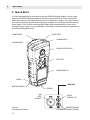
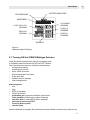
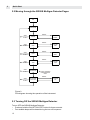
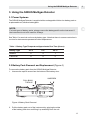
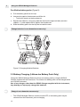
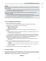
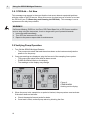
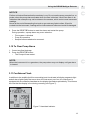
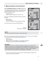
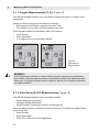
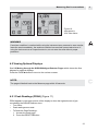
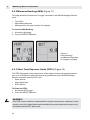
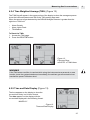
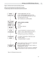
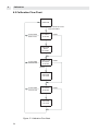
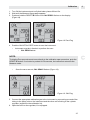
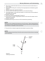
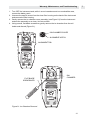
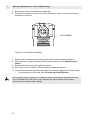
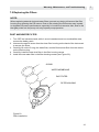
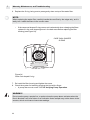
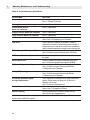

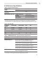
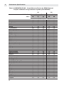

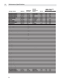
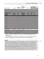

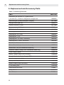


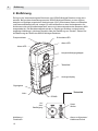
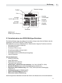
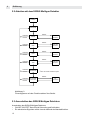
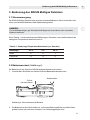
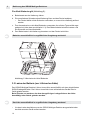
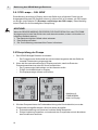
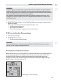
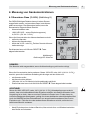
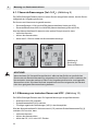
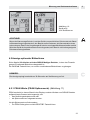
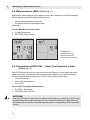
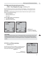
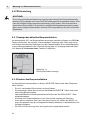
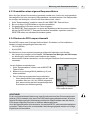
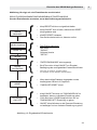
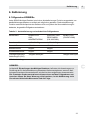
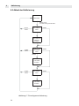
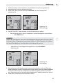
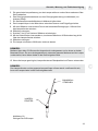
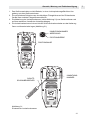
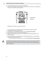
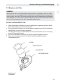
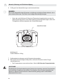
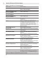
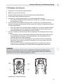
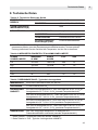
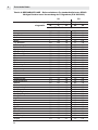
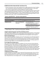
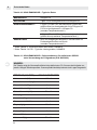
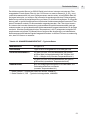
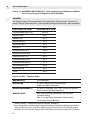
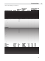
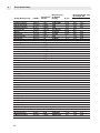
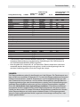
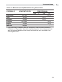
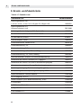

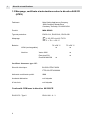
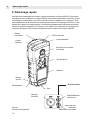
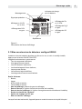
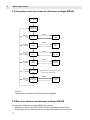
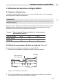
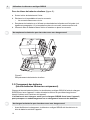

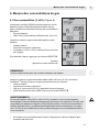
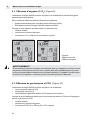
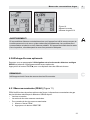
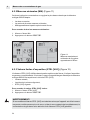
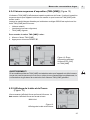
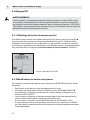
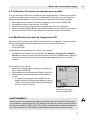
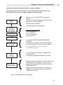
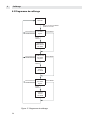
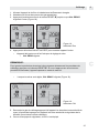
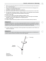
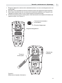
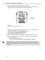
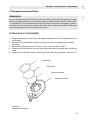
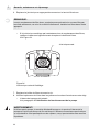
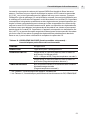
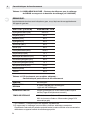

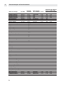
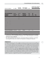

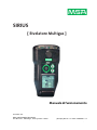
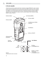
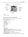
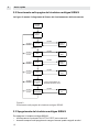

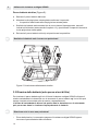
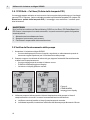
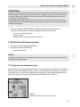
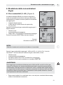
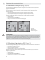
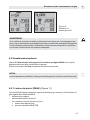
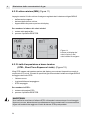
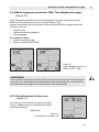
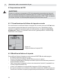
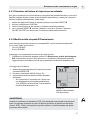
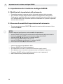
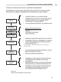
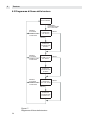
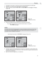
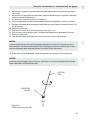
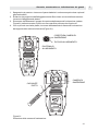
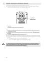
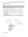
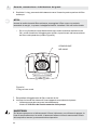
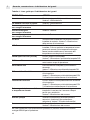
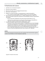
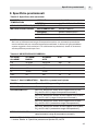

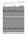
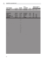
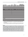
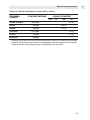


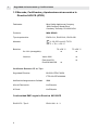
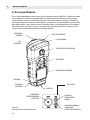
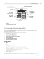
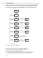
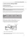


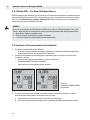
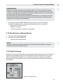
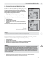
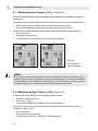
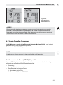
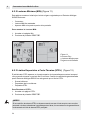
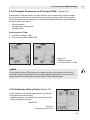
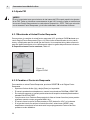
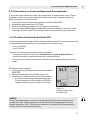
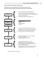
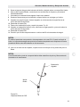
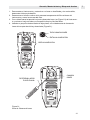
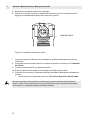
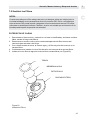
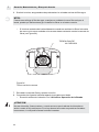
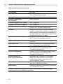
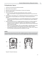
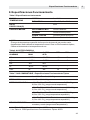
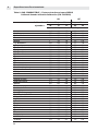
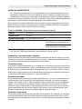
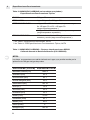
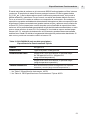
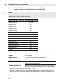

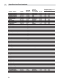
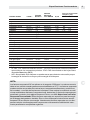


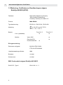
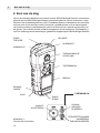
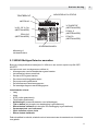
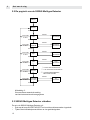
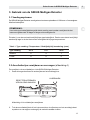
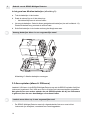
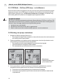

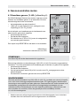
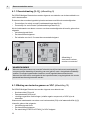
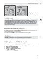
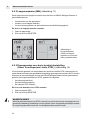

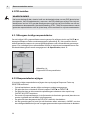
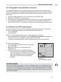
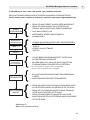
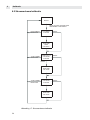
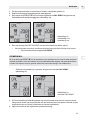

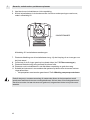
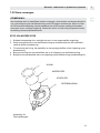
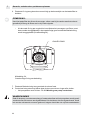
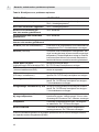
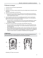
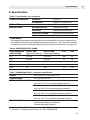
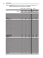
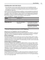
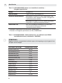


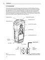
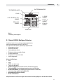
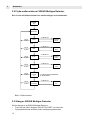
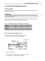
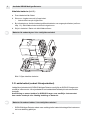
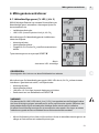
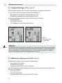
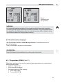
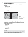
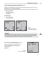
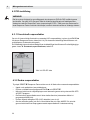
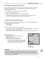
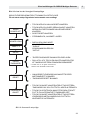
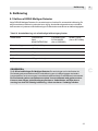
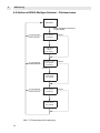
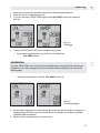
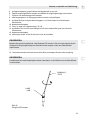

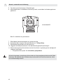
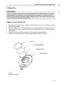
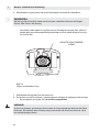
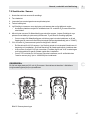
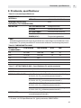

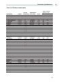
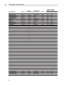
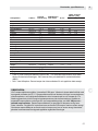


![SIRIUS® [ MultiGas Detector ] - Ex-Ox](http://vs1.manualzilla.com/store/data/005943422_1-205976de5d5a2c1a8aefcbb2de78019a-150x150.png)