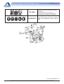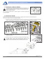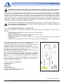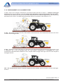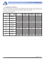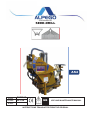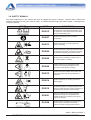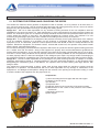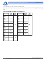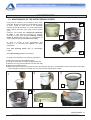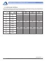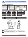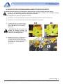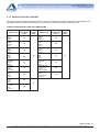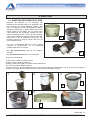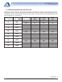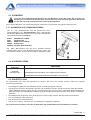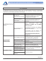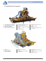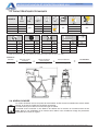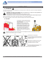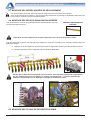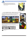
1
6(0,1$75,&( $6 Codice Da matr: D15834/2 32150 , MANUALE D’USO E MANUTENZIONE A matr: ISTRUZIONI ORIGINALI MANUALE SEMINATRICE PNEUMATICA AS4 Old Cod.D15834 New Cod. MANT2010/00636 R.2 ALPEGO S.p.a. Sede Amministrativa: Via torri di Confine, 6 36053 GAMBELLARA (VICENZA) - ITALY - MACCHINE PER LA LAVORAZIONE DEL TERRENO - ERPICI ROTANTI FISSI E PIEGHEVOLI - COLTIVATORI A DENTI ED A DISCHI - SEMINATRICI MECCANICHE, PNEUMATICHE E COMBINATE - DISSODATORI E RIPUNTATORI - FRESATRICI E ZAPPATRICI - TRINCIASARMENTI - TRINCIASTOCCHI Sede legale: Via Giovanni e Giuseppe Cenzato,9 36045 LONIGO (VICENZA) - ITALY Tel +39 0444/64.61.00 Fax +39 0444/64.61.99 e-mail : [email protected] web site : www.alpego.com I GB D F E Dichiarazione CE di conformità’ ai sensi della direttiva CE 2006/42 EC Certificate of conformity conforming to EEC Directions 2006/42 EG Konformitatserklarung entsprechend der EG-Richtlinie 2006/42 EWG Wir Déclaration de conformité pour la CE conforme à la directive de la 2006/42 CE Nous Declaraciòn CE de conformidad. Conforme a la directiva CE 2006/42 la empresa / el productor La ditta sottoscritta We ALPEGO s.r.l. VIA TORRI DI CONFINE N°6 36053 GAMBELLARA -(VI)-ITALIA dichiara sotto la propria responsabilità’ che la macchina modello : Codice / Code: declare in sole responsability, that the product model : to which this applies, conforms to the basic safety and health requirements of EC Directions 2006/42 Per l’adeguamento For the adaptation of delle macchine it blots some have sono state adottate been adopted the norms: le norme: Gambellara: déclarons sous notre seule responsabilite’ que le produict modéle : MODELLO MACCHINA SEMINATRICI «SEMIN_AS3__40032_IDRO_PLUS» È’ Conforme ai requisiti Essenziali di Sicurezza e di Tutela della Salute di cui alla Direttiva CE 2006/42 UNI EN 708 UNI EN ISO 4254-1 UNI EN 14018 UNI EN 982 ISO 3757-2 ISO 11684 erklaren in alleineger Verantwortung, da das Produkt Typ : UNI EN 708 UNI EN ISO 4254-1 UNI EN 14018 UNI EN 982 ISO 3757-2 ISO 11684 declara bajo su propia responsabilidad que la màquina modelo: N° matricola / serial n°: auf das sich diese Erklarung bezeith, den einschlagigen grundlegenden Sicherheits und Gesundheitsanforderungen der EG-Richtlinie 2006/42 EWG Für die Anpassung von ihr befleckt einiges sind angenommen worden den Normen: faisant l’objet de la déclaration est conforme aux prescriptions fondamentales en matière de sècuritè et de santè stipulèes dans la Directive de la CE 2006/42 Pour l'adaptation d'elle en éponge ont été adoptés les normes : està conforme a los requisitos esenciales de seguridad y de defeusa de la salud de la directiva CE 2006/42 Para la equparaciòn de las màquinas nan sido adoptado las normas UNI EN 708 UNI EN ISO 4254-1 UNI EN 14018 UNI EN 982 ISO 3757-2 ISO 11684 UNI EN 708 UNI EN ISO 4254-1 UNI EN 14018 UNI EN 982 ISO 3757-2 ISO 11684 UNI EN 708 UNI EN ISO 4254-1 UNI EN 14018 UNI EN 982 ISO 3757-2 ISO 11684 La ditta 2 Copyright ©2009 della Alpego spa ® -Tutti i diritti sono riservati. È espressamente vietata la ristampa o l’uso non autorizzato per iscritto da parte di Alpego spa MANUALE SEMINATRICE PNEUMATICA AS4 Old Cod.D15834 New Cod. MANT2010/00636 R.2 Consultare attentamente questo manuale prima di utilizzare la macchina, la sua conoscenza è indispensabile per l’utilizzo in sicurezza, va conservato per tutta la durata della macchina. Vi ringraziamo per la scelta fatta, avete acquistato un prodotto di ottima qualità,garantito da una decennale esperienza. Ogni macchina prima di uscire dalla fabbrica viene accuratamente ispezionata per garantirla da ogni difetto.Nell’eventualità che si manifesti ugualmente qualche difetto di materiale interpellate subito il vostro concessionario. Con l’obiettivo di migliorare costantemente il prodotto e di mantenerlo ai massimi livelli siamo a vostra disposizione per fornirvi ogni chiarimento o informazione. FATE ATTENZIONE AL TRIANGOLO, INDICA PERICOLO LA DEFINIZIONE MACCHINA , SOSTITUISCE LA DENOMINAZIONE COMMERCIALE A CUI FA RIFERIMENTO IL MANUALE IN OGGETTO Le illustrazioni riportate nel presente manuale hanno valore puramente indicativo. Possono pertanto presentare delle piccole differenze che sono ininfluenti per le istruzioni riportate nel manuale stesso N.B. : Vista convenzionale della macchina normalmente la ditta ALPEGO considera la macchina vista da dietro rispetto al senso di marcia; questo per poter individuare i particolari e le corrette posizioni di montaggio che devono essere rispettate per i pezzi che riportano nella descrizione “ destro o sinistro”. (Es.: cardano destro o sinistro, zappa destra o sinistra ecc.) 3 Copyright ©2009 della Alpego spa ® -Tutti i diritti sono riservati. È espressamente vietata la ristampa o l’uso non autorizzato per iscritto da parte di Alpego spa Sommario 1. INFORMAZIONI GENERALI ..................................................................................................................................... 1 1.1. SCOPO DEL MANUALE ...................................................................................................................................... 1 1.2. DOCUMENTAZIONE ALLEGATA ALLA MACCHINA ......................................................................................... 1 1.3. GARANZIA ........................................................................................................................................................... 1 1.4. IDENTIFICAZIONE DELLA MACCHINA ............................................................................................................ 1 2. SPECIFICHE TECNICHE ........................................................................................................................................... 2 2.1. DESCRIZIONE ..................................................................................................................................................... 2 2.2. DESCRIZIONE DELLA MACCHINA .................................................................................................................... 3 2.3. tabella dati tecnici ................................................................................................................................................. 4 2.4. LIVELLO SONORO .............................................................................................................................................. 4 3. NORME DI SICUREZZA ............................................................................................................................................ 5 3.1. USO IN SICUREZZA ........................................................................................................................................... 5 3.2. COLLEGAMENTO IDRAULICO........................................................................................................................... 6 3.3. INSTALLAZIONE COMPONENTI ELETTRICI ED ELETTRONICI ..................................................................... 7 3.4. MANUTENZIONE IN SICUREZZA ..................................................................................................................... 7 3.5. CIRCOLAZIONE STRADALE .............................................................................................................................. 8 3.6. ABBIGLIAMENTO ................................................................................................................................................ 8 3.7. ECOLOGIA........................................................................................................................................................... 8 3.8. SEGNALI DI SICUREZZA.................................................................................................................................... 9 4. INSTALLAZIONE ..................................................................................................................................................... 11 4.1. trasporto ............................................................................................................................................................. 11 4.2. SOLLEVAMENTO .............................................................................................................................................. 11 4.3. APPLICAZIONE AGGANCIO RAPIDO TRAMOGGIA ...................................................................................... 12 4.4. APPLICAZIONE SU ATREZZATURA................................................................................................................ 13 4.5. montaggio barra di semina................................................................................................................................ 14 4.6. Montaggio radar ................................................................................................................................................. 14 4.7. Montaggio erpice copriseme .............................................................................................................................. 15 4.8. MONTAGGIO TABELLA LUCI POSTERIORI ................................................................................................... 15 4.9. MONTAGGIO TUBI DI SEMINA ........................................................................................................................ 16 4.10. COLLEGAMENTO TRA TRAMOGGIA ANTERIORE E SEMINATRICE ........................................................ 19 4.11. VERIFICA DI CAPACITÀ DI SOLLEVAMENTO E STABILITÀ DELLA TRATTRICE ..................................... 20 5. ISTRUZIONI PER L’USO ......................................................................................................................................... 21 5.1. SISTEMA DI ALIMENTAZIONE E TRASPORTO DEL SEME .......................................................................... 21 5.1.1. COLLEGAMENTO IDRAULICO AL TRATTORE ........................................................................................ 22 5.1.2. COLLEGAMENTO IDRAULICO A TRATTORI CON CIRCUITO IDRAULICO A “CENTRO APERTO” ..... 23 5.1.3. REGOLAZIONE DI FLUSSO SENZA POMPA A PORTATA VARIABILE .................................................. 23 5.1.4. MESSA IN FUNZIONE DELL’ALIMENTATORE ......................................................................................... 24 5.1.5. IMPOSTAZIONE TEMPO DI CARICA ........................................................................................................ 25 5.1.6. FUNZIONAMENTO CICLI ALIMENTATORE .............................................................................................. 26 5.2. AZIONAMENTO DELLA SOFFIANTE ............................................................................................................... 27 5.2.1. COLLEGAMENTO IDRAULICO AL TRATTORE ........................................................................................ 27 5.2.2. REGOLATORE DI FLUSSO SENZA POMPA A PORTATA VARIABILE ................................................... 28 5.3. DISTRIBUZIONE ............................................................................................................................................... 28 5.4. SGANCIO DELLA SEMINATRICE .................................................................................................................... 28 6. MANUTENZIONE ..................................................................................................................................................... 29 6.1. Manutenzione filtro aspiratore ............................................................................................................................ 29 6.2. VERIFICHE E CONTROLLI ............................................................................................................................... 30 6.3. lubrificazione ...................................................................................................................................................... 31 6.3.1. LUBRIFICAZIONE MOLTIPLICATORE SOFFIANTE. ................................................................................ 31 6.4. LUBRIFICAZIONE INGRASSATORI. ................................................................................................................ 31 6.5. messa a riposo ................................................................................................................................................... 31 7. ANOMALIE ............................................................................................................................................................... 32 8. ACCESSORI............................................................................................................................................................. 34 Copyright ©2009 della Alpego spa ® -Tutti i diritti sono riservati. È espressamente vietata la ristampa o l’uso non autorizzato per iscritto da parte di Alpego spa MANUALE SEMINATRICE PNEUMATICA AS4 Old Cod.D15834 New Cod. MANT2010/00636 R.2 1. INFORMAZIONI GENERALI 1.1. SCOPO DEL MANUALE Questo manuale e’ stato redatto dal costruttore della macchina e fa parte integrante della documentazione allegata alla macchina Il manuale definisce lo scopo per cui e’ stata costruita la macchina , ne stabilisce la corretta applicazione e i limiti di utilizzazione. La costante applicazione delle indicazioni riportate in questo manuale garantisce la sicurezza delle persone che utilizzano la macchina, l’economia di esercizio e una più’ lunga durata della macchina. Il presente manuale e’ stato suddiviso in vari paragrafi , per facilitare la ricerca degli argomenti, consultare l’indice iniziale. Le illustrazioni riportate nel presente manuale sono fornite a titolo esemplificativo anche se sono sensibilmente differenti dalla macchina in vostro possesso, la sicurezza e le informazioni sono comunque garantite. 1.2. DOCUMENTAZIONE ALLEGATA ALLA MACCHINA Con la macchina deve essere allegata la seguente documentazione: • • • Manuale uso e manutenzione Dichiarazione CE di conformità Catalogo ricambi La macchina può essere fornita di diversi accessori / allestimenti. Per l’istallazione e l’uso di questi far riferimento ai relativi manuale forniti assieme alla documentazione della macchina. COD. D16555 Q00A00129 Q00A00134 Q00A00132 D16347 DESCRIZIONE Manuale uso e manutenzione dosatore DOSAL Manuale uso e manutenzione dischi segnafile Manuale uso e manutenzione barra di semina Manuale uso e manutenzione pettine copriseme Manuale uso e manutenzione computer Alpetronic Power 1.3. GARANZIA Controllare all’atto della consegna che la macchina e gli eventuali accessori non abbiano subito danni durante il trasporto. Eventuali reclami devono essere presentati per iscritto entro 6 giorni. DECADENZA DELLA GARANZIA La garanzia decade immediatamente: • qualora si dovesse verificare un errore di manovra • per insufficiente manutenzione della frizione dell’albero cardanico • qualora si dovesse oltrepassare il limite di potenza consentito (vedi tabella 2.2) • qualora non fossero seguite le istruzioni descritte nel presente manuale • qualora non fossero usati ricambi originali • qualora venisse apportata qualsiasi modifica senza autorizzazione del costruttore 1.4. IDENTIFICAZIONE DELLA MACCHINA In corrispondenza dei 3 punti di attacco alla trattrice è fissata la targhetta di identificazione della macchina che riporta i seguenti dati: 1. Modello della macchina 2. Numero di matricola 3. Peso massimo della macchina 4. Data di costruzione [es: 1305 = 13 (2013) + 05 (maggio)] Il peso indicato è relativo alla macchina completa di tutti gli accessori INFORMAZIONI GENERALI - 1 Copyright ©2009 della Alpego spa ® -Tutti i diritti sono riservati. È espressamente vietata la ristampa o l’uso non autorizzato per iscritto da parte di Alpego spa MANUALE SEMINATRICE PNEUMATICA AS4 Old Cod.D15834 New Cod. MANT2010/00636 R.2 2. SPECIFICHE TECNICHE 2.1. DESCRIZIONE mod. AS4 deve essere utilizzata solamente per lavorare terreni ad uso agricolo, ogni altro uso diverso da quello descritto in queste istruzioni può provocare danno alla macchina e costituire un pericolo per l’utilizzatore. La seminatrice mod. AS4 può lavorare per mezzo di un apposito kit di montaggio in combinazione con attrezzature per la lavorazione del terreno l’utilizzatore. La seminatrice mod. AS4 consta principalmente di due cantieri separati connessi tra loro mediante un tubo spiralato per il trasporto del seme tra i due. Una tramoggia principale, di litri 1400 di capacità (espandibile fino a 2000 litri), disposta anteriormente al trattore, non necessita di prese idrauliche e di potenza (PTO), solo di una connessione elettrica per le luci anteriori e funge solamente da serbatoio del seme. Posteriormente alla trattrice si trova la macchina combinata vera e propria: in essa sono visibili il sistema di aspirazione che porta dietro il seme qualora ve ne sia richiesta e in maniera totalmente automatica, un serbatoio secondario di momentaneo accumulo, la tramoggia secondaria di alimentazione diretta del dosatore, il sistema distributore con finale barra di semina. La macchina così concepita permette la combinazione di una seminatrice con preparatore pieghevole, in quanto la tramoggia secondaria e compressa trasversalmente, mantenendo al completo apparato di dosatura il più vicino possibile a quello distributore limitando al massimo gli effetti dannosi di un lungo percorso fatto dal seme tra dosatore e assolcatori. La seminatrice mod. AS4 è idonea per la semina di cereali: frumento, orzo, segala, avena, riso; per sementi fine e foraggere: colza, trifoglio, erba medica e per sementi grosse: soia, piselli. Le sementi vengono depositate nel terreno a mezzo di organi assolcatori, falcione o disco e distribuite in modo continuo; le quantità da distribuire vengono regolate attraverso uno speciale dosatore rotante il cui movimento è ottenuto da una ruota aderente al terreno. La distribuzione e Il trasporto del seme agli assolcatori avviene tramite aria compressa prodotta da apposito ventilatore mosso dalla presa di forza del trattore o idraulicamente nelle Vers Plus L‘assolcatore a disco o stivaletto sprint è montato su supporto super-elastico che permette una ottima profondità e pressione su terreno regolando l’altezza della barra di semina. • La seminatrice • • • • • • Per il progetto e la realizzazione della macchina in oggetto sono state esaminate e seguite le Norme della direttiva 98/37CE quali: UNI EN 14018 UNI EN 1553 UNI EN 982 ISO 11684 ISO 3757-2 La seminatrice AS4 è stata realizzata per la combinazione con erpici di tipo “ALPEGO” in quanto garantisce il rispetto della normativa EN 708 Dal corretto uso e dall’adeguata manutenzione dipende il regolare funzionamento della macchina è consigliabile quindi osservare quanto descritto in questo manuale allo scopo di prevenire qualsiasi inconveniente che potrebbe pregiudicare il buon funzionamento e la sua durata. È importante attenersi a quanto descritto nel presente manuale in quanto la Ditta Costruttrice declina ogni responsabilità dovuta a negligenza ed alla mancata osservanza di tali norme. La Ditta Costruttrice, è comunque a completa disposizione per assicurare assistenza tecnica e tutto ciò che può essere necessario per il miglior funzionamento e la massima resa della macchina. SPECIFICHE TECNICHE - 2 Copyright ©2009 della Alpego spa ® -Tutti i diritti sono riservati. È espressamente vietata la ristampa o l’uso non autorizzato per iscritto da parte di Alpego spa MANUALE SEMINATRICE PNEUMATICA AS4 Old Cod.D15834 New Cod. MANT2010/00636 R.2 2.2. DESCRIZIONE DELLA MACCHINA A. B. C. D. E. Tubo aspirazione seme Cofano copri alimentatore Filtro polveri fini Serbatoio alimentatore Scatola elettrica di controllo F. Sportello per visione interna cofano G. Soffiante H. Tramoggia secondaria alimentazione dosatore I. Cilindri idraulici chiusura K. Disco segnafile L. Tubo convogliatore aria al dosatore M. Supporto dischi segnafile N. Tubi idraulici O. Sistema regolazione rullo P. R. S. T. Gruppo dosatore Fungo distributore Tubi trasporto seme assolcatore Assolcatore U. Pettine copriseme V. Radar W. Gruppo regolazione barra di semina X. Y. Z. Tenditore tubi trasporto seme Tubo iniezione aria in soffiante Segnaletica luminosa posteriore SPECIFICHE TECNICHE - 3 Copyright ©2009 della Alpego spa ® -Tutti i diritti sono riservati. È espressamente vietata la ristampa o l’uso non autorizzato per iscritto da parte di Alpego spa MANUALE SEMINATRICE PNEUMATICA AS4 Old Cod.D15834 New Cod. MANT2010/00636 R.2 2.3. TABELLA DATI TECNICI MOD. cm AS4 - 400 AS4 - 450 AS4 - 500 AS4 - 600 MOD. 400 450 500 600 cm N° cm 250 32 36 40 40 12.5 12.5 12.5 15 MOD. * MOD. * dm Tot min Lit/min 3 90 100 * AS4 - 400 570 AS4 - 400 624 AS4 - 400 92 AS4 - 450 AS4 - 500 AS4 - 600 620 670 - AS4 - 450 AS4 - 500 AS4 - 600 680 734 804 AS4 - 450 AS4 - 500 AS4 - 600 94 96 96 + 460 - 490 470 - 500 480 - 510 490 - 520 400 MOD. AS4 - 400 100 AS4 - 450 AS4 - 500 AS4 - 600 103 108 112 dischi segnafile = 192 * = Peso di 2 barre di semina + kit attacco (kit spaglio serie 5 per barra di semina a spaglio) ESEMPIO: AS4-400 475 Kg + barra di semina a dischi 624 Kg + pettine copriseme 100 Kg + 192 Kg Tot. Macchina 1391 Kg 2.4. LIVELLO SONORO Se il trattore è equipaggiato di cabina il livello sonoro dipenderà dal livello di isolamento della cabina stessa. Se il trattore non è equipaggiato di cabina o funziona con i finestrini aperti il livello di rumore emesso dalla macchina in lavoro misurato ad una distanza di 200 mm. dalla finestra posteriore è superiore a 85 dBa , per cui si consiglia l’uso di cuffie di protezione come previsto dalle norme di diversi paesi. SPECIFICHE TECNICHE - 4 Copyright ©2009 della Alpego spa ® -Tutti i diritti sono riservati. È espressamente vietata la ristampa o l’uso non autorizzato per iscritto da parte di Alpego spa MANUALE SEMINATRICE PNEUMATICA AS4 Old Cod.D15834 New Cod. MANT2010/00636 R.2 3. NORME DI SICUREZZA 3.1. USO IN SICUREZZA • Leggere attentamente i manuali per l’uso e la manutenzione prima di procedere alle operazioni di avviamento , uso e manutenzione della attrezzatura. • Il costruttore declina ogni responsabilita’ per danni a persone , animali o cose causati dalla inosservanza delle norme di sicurezza. • E’ assolutamente vietato utilizzare la macchina per un uso diverso da quello espressamente indicato in questo libretto. • Evitare assolutamente di toccare in qualsiasi modo le parti in movimento. • La macchina ed i suoi eventuali accessori per il trasporto su strada devono essere muniti di segnalazioni e protezioni adeguate. • • E assolutamente vietato condurre o far condurre il trattore da personale non in possesso di patente di guida adeguata, inesperto e non in buone condizioni di salute. • Esaminare attentamente le etichette adesive riportate sulla macchina e rispettare le indicazioni in esse contenute. Le decalcomanie relative alla sicurezza devono essere sempre ben evidenti:vanno tenute pulite e vanno sostituite se diventano poco leggibili (eventualmente possono essere rìchieste al concessionario). • Durante le manovre non permettere l’avvicinamento di persone o animali al raggio di azione della macchina • Durante il lavoro non permettere l’avvicinamento di persone, animali e cose al raggio di azione delle zolle e delle pietre proiettate dalla macchina. • E’ assolutamente vietato intromettersi nella zona tra il trattore e la macchina per azionare i comandi esterni del sollevatore idraulico. • Rimanere sempre seduti sul posto di guida della trattrice e scendere solamente quando la presa di forza della trattrice è disinserita e il freno di stazionamento della trattrice e’ inserito. • Durante le pause di lavoro disinserire la presa di forza ,spegnere il motore, appoggiare la macchina sul terreno e inserire il freno di stazionamento del trattore. • Non lavorare con protezioni rimosse. • Non utilizzare la macchina come mezzo di trasporto di persone animali o cose. • Non lavorare su terreni o luoghi che possono compromettere la stabilità della macchina. • Conoscere bene l’area in cui si sta lavorando. Non operare mai in un area in cui vi siano ostacoli come pietre bastoni o radici in quanto rovinerebbero l’integrità della macchina. • Per il trasporto su strada usare sempre il lampeggiante di pericolo. • Per la circolazione su strada rispettare le norme vigenti nel proprio paese. E’ molto importante ricordare che la tenuta di strada , la capacità di frenatura e la direzione sono influenzati dal peso della macchina applicata al sollevatore del trattore; nelle curve inoltre considerare l’azione della forza centrifuga che sposta il baricentro della macchina NORME DI SICUREZZA - 5 Copyright ©2009 della Alpego spa ® -Tutti i diritti sono riservati. È espressamente vietata la ristampa o l’uso non autorizzato per iscritto da parte di Alpego spa MANUALE SEMINATRICE PNEUMATICA AS4 Old Cod.D15834 New Cod. MANT2010/00636 R.2 • Evitare di far girare a vuoto (fuori del terreno) la macchina. Durante il lavoro evitare di effettuare curve con la macchina interrata, ne tanto meno lavorare in retromarcia. SolIevarla sempre per i cambiamenti di direzione e le inversioni di marcia. • Durante il trasporto, od ogni qualvolta si renda necessario il sollevamento della macchina, è opportuno che il gruppo di sollevamento del trattore venga regolato in modo che la macchina stessa non sia sollevata da terra per più di 35 cm circa. Evitare di immettersi su strade pubbliche con la macchina sporca di terra, erba o altro che produca sporcizia ed intralcio al traffico stradale. Non far cadere con violenza la macchina sul terreno ma farla scendere lentamente per consentire il graduale inserimento delle lame nel terreno. In caso contrario si provocherebbero forti sollecitazioni su tutti i componenti della macchina stessa che potrebbero comprometterne la loro integrità. • In fase di trasporto su strada, con la macchina sollevata, mettere in posizione dl blocco la leva d comando del sollevatore idraulico del trattore. • Non utilizzare la macchina all’interno di strutture chiuse a meno che non vi sia una adeguata ventilazione • Utilizzare solamente l’albero cardanico previsto dal costruttore, dotato delle sicurezze contro i sovraccarichi. • Prima di inserire la presa di forza, accertarsi del numero di giri prestabilito. Non scambiare Il regime di 540 giri/min con 1000 g/min. • L’installazione e lo smontaggio del albero cardanico deve essere sempre fatta a motore spento. • La protezione dell’albero cardanico deve essere sempre efficiente, va controllata periodicamente , e fissata con le catenelle per impedirne la rotazione. • Disinserire sempre la Presa di Forza quando l’albero cardanico fa un angolo superiore ai 15°, vedi figura. • Prima di inserire la presa di forza assicurarsi che non vi siano persone o animali nella zona d’azione e che il regime scelto corrisponda a quello consentito. Mai superare il massimo previsto • Per evitare scottature non toccare il cambio di velocità dopo un uso prolungato della macchina. • Prima di effettuare la sostituzione degli ingranaggi nel cambio di velocità disinserire la presa di forza, inserire il freno di stazionamento e togliere la chiave di avviamento, quindi rimontare il coperchio del cambio prima di riavviare la macchina. 3.2. COLLEGAMENTO IDRAULICO • Al momento dell’allacciamento dei tubi idraulici all’impianto idraulico del trattore, fare attenzione che gli impianti idraulici della macchina operatrice e della trattrice non siano in pressione. • In caso di collegamenti funzionali di tipo idraulico tra trattrice e macchina operatrice, prese e spine dovrebbero essere contrassegnate per mezzo di colori, in modo da escludere impieghi errati. Ove si verificasse uno scambio, sussisterebbe il pericolo di incidente. • L’impianto idraulico si trova sotto alta pressione; per evitare il pericolo d’infortunio, in caso di ricerca di punti di perdita vanno utilizzati gli strumenti ausiliari idonei. • Non superare mai la pressione prevista dell’impianto oleodinamico. NORME DI SICUREZZA - 6 Copyright ©2009 della Alpego spa ® -Tutti i diritti sono riservati. È espressamente vietata la ristampa o l’uso non autorizzato per iscritto da parte di Alpego spa MANUALE SEMINATRICE PNEUMATICA AS4 Old Cod.D15834 New Cod. MANT2010/00636 R.2 3.3. INSTALLAZIONE COMPONENTI ELETTRICI ED ELETTRONICI • La macchina è dotata di componenti elettronici il cui funzionamento può influire su altri strumenti attraverso la trasmissione elettromagnetica. Tali influssi possono mettere a rischio le persone qualora non vengano rispettate le seguenti istruzioni di sicurezza. • In caso di installazione successiva di,strumentì e/o componenti elettrici ed elettronici sulla macchina, con collegamento alla rete di bordo, l'utente deve testare sotto la propria responsabilità se l'installazione provochi anomalìe all'elettronica dei veicolo o di altri componenti. • In particolare modo accertarsi che i componenti elettrici ed elettronici installati successivamente siano conformi alla direttiva CEM 891336/CEE nella rispettiva stesura vigente e che siano provvisti di marchio CE. • Per l'installazione successiva di sistemi di comunicazione mobile (ad es. radio, telefono) devono essere rispettati anche i seguenti requisiti: 1. Installare solo apparecchiature conformi alle normative nazionali vigenti (ad es. omologazione BZT per la Germania). 2. Installare l'apparecchiatura in modo fisso. 3. L'uso di apparecchi mobili o portatili nel veicolo è consentito esclusivamente mediante il collegamento ad un'antenna esterna fissa. 4. Montare il trasmettitore ben distanziato dall'elettronica dei veicolo. 5. Quando si installa l'antenna assicurarsi di un'installazione a regola d'arte con un buon collegamento di massa tra antenna e massa dei veicolo. Per il cabiaggio, l'installazione e l'assorbimento di corrente massimo ammesso osservare anche le istruzioni di montaggio dei costruttore della macchina. 3.4. MANUTENZIONE IN SICUREZZA • Non permettere a persone non autorizzate di effettuare operazioni di manutenzione o di fare qualsiasi altro tipo di intervento sulla macchina. • La manutenzione e le riparazioni vanno effettuate in officine opportunamente attrezzate. • In caso di manutenzione della macchina disinnestare i tubi idraulici dalle prese del trattore. • Utilizzare sempre accessori e ricambi originali per rispettare le esigenze richieste dal costruttore in caso contrario oltre a decadere la garanzia si possono causare anomalie di funzionamento che pregiudicano la sicurezza della macchina. • Rispettare la conformità degli olii consigliati. • Nell’effettuare qualsiasi operazione sulla macchina disinserire la presa di forza della trattrice, inserire il freno di stazionamento togliere la chiave di avviamento e fare attenzione che altre persone non salgano sulla trattrice. • Prima di pulire e ingrassare l’albero cardanico disinserire la Presa di Forza ,spegnere il motore, inserire il freno di stazionamento e togliere la chiave di avviamento NORME DI SICUREZZA - 7 Copyright ©2009 della Alpego spa ® -Tutti i diritti sono riservati. È espressamente vietata la ristampa o l’uso non autorizzato per iscritto da parte di Alpego spa MANUALE SEMINATRICE PNEUMATICA AS4 Old Cod.D15834 New Cod. MANT2010/00636 R.2 3.5. CIRCOLAZIONE STRADALE Se necessario la macchina può essere trasportata su strada agganciata al trattore; l’operatore deve verificare, confrontare ed adeguare l’attrezzatura per il pieno rispetto delle Norme del Codice della Strada nel paese di utilizzo. Si deve tenere presente in particolar modo: 1. per l’aggancio della macchina al trattore è necessario seguire le istruzioni riportate nel presente manuale 2. durante il trasporto è necessario mantenere la macchina bloccata e sollevata da terra 3. obbligo del rispetto delle norme per la salvaguardia della propia incolumità e quella degli altri, adottando tutte le precauzioni possibili. 4. devono essere previste le protezioni per gli elementi sporgenti e fuori sagoma 5. l’intera attrezzatura deve essere equipaggiata di appropiato impianto di illuminazione con elementi di segnalazione e lampeggiante 6. dove previsti, devono essere applicati i cartelli di segnalazione della sagoma 7. la capacità di frenatura e la direzione sono influenzati dal peso della macchina applicata al sollevatore del trattore; nelle curve inoltre considerare l’azione della forza centrifuga che sposta il baricentro della macchina. 3.6. ABBIGLIAMENTO Indossare sempre indumenti che proteggano il corpo senza parti penzolanti che potrebbero impigliarsi su componenti in movimento, togliere inoltre orologi, anelli, collane etc. che potrebbero rappresentare lo stesso pericolo. Raccogliere i capelli lunghi. Se richiesto dalle normative vigenti nel proprio paese l’utilizzatore della macchina dovrà indossare idonei mezzi di protezione: (tuta, mascherina, cuffie , scarpe, guanti ecc.) 3.7. ECOLOGIA Rispettare le leggi in vigore nel proprio paese relativamente all’uso ed allo smaltimento dei prodotti impiegati per la lubrificazione , la manutenzione e la pulizia della macchina; osservare attentamente le indicazioni riportate sulle confezioni dei prodotti stessi. Rispettare le norme in vigore anche in caso di rottamazione della macchina. NORME DI SICUREZZA - 8 Copyright ©2009 della Alpego spa ® -Tutti i diritti sono riservati. È espressamente vietata la ristampa o l’uso non autorizzato per iscritto da parte di Alpego spa MANUALE SEMINATRICE PNEUMATICA AS4 Old Cod.D15834 New Cod. MANT2010/00636 R.2 3.8. SEGNALI DI SICUREZZA Le varie etichette adesive presenti sulla macchina servono a segnalare la fonte del pericolo , osservatele attentamente e seguite le indicazioni per l’utilizzo della macchina in sicurezza., vanno mantenute pulite e leggibili se danneggiate vanno sostituite FIGURA CODICE INDICAZIONI D02612 Prima di utilizzare la attrezzatura e’ obbligatorio leggere il libretto uso e manutenzione ed i consigli sulla sicurezza ed osservare tutte le istruzioni durante l’uso D02627 Indica il punto di aggancio per il trasporto della macchina D02613 Indica il pericolo di cesoiamento durante i movimenti in lavoro della macchina D02624 Indica il pericolo causato dall’olio in pressione nel caso di rottura dei tubi idraulici, consultare il manuale istruzioni prima di effettuare operazioni di riparazione sugli impianti idraulici D02609 Indica il divieto assoluto di salire sopra la macchina durante il lavoro D02608 Indica il pericolo di attorcigliamento durante il lavoro sull’albero cardanico, consiglia di non avvicinarsi all’albero in rotazione D02615 Indica la necessita di spegnere la trattrice e togliere la chiave di avviamento durante le operazioni di manutenzione D02614 Indica il pericolo di stritolamento sugli ingranaggi del cambio di velocità, consiglia di disinserire la presa di forza durante la sostituzione degli ingranaggi. D02616 Indica la posizione di una gamba di sostegno che deve sempre essere bloccata nei periodi di non utilizzo per mantenere le condizioni di stabilità della macchina D02621 Nelle operazioni di chiusura degli erpici pieghevoli indica il pericolo di corpi in movimento e fa divieto di sostare nel raggio di azione della macchina D10238 Indica che il tubo di alimentazione da ½” della turbina deve essere collegato al distributore con portata prioritaria D10239 Indica che il tubo di ritorno da ¾” deve essere collegato al serbatoio del olio che non abbia una contropressione max 5 Bar NORME DI SICUREZZA - 9 Copyright ©2009 della Alpego spa ® -Tutti i diritti sono riservati. È espressamente vietata la ristampa o l’uso non autorizzato per iscritto da parte di Alpego spa MANUALE SEMINATRICE PNEUMATICA AS4 D11445 Q15A00531 Old Cod.D15834 New Cod. MANT2010/00636 R.2 Indica i punti di sollevamento della seminatrice singolarmente oppure combinata con erpice o preparatore. Fare molta attenzione che i ganci di sollevamento della seminatrice NON SONO adatti a sollevare l’ attrezzatura combinata. Indica i DPI (dispositivi di protezione individuale) previsti: tuta, mascherina, cuffie, scarpe e guanti. NORME DI SICUREZZA - 10 Copyright ©2009 della Alpego spa ® -Tutti i diritti sono riservati. È espressamente vietata la ristampa o l’uso non autorizzato per iscritto da parte di Alpego spa MANUALE SEMINATRICE PNEUMATICA AS4 Old Cod.D15834 New Cod. MANT2010/00636 R.2 4. INSTALLAZIONE 4.1. TRASPORTO La macchina può essere facilmente trasportata, su lunghi percorsi con adeguati mezzi di trasporto: autocarri, rimorchi, carri ferroviari, ecc. Le operazioni di carico e scarico della macchina possono essere molto pericolose se non effettuate con la massima attenzione: allontanare i non addetti; sgomberare e delimitare la zona di carico; verificare l’integrità e l’idoneità dei mezzi a disposizione. Ci si deve accertare inoltre che la zona in cui si agisce, sia sgombra e che vi sia uno spazio di fuga sufficiente, cioè una zona libera e sicura in cui potersi spostare rapidamente qualora la macchina cadesse. Tali operazioni devono essere essere eseguite solo da personale addestrato a questo tipo di manovre. Prima di procedere con l’operazione di carico, verificare che il mezzo disponibile sia abilitato a tale trasporto e che abbia la capacità di portare il peso della macchina. Controllare a tal proposito la TABELLA DATI TECNICI (vedi paragrafo 2.3) per il peso della macchina. Questi ultimi sono inoltre utili per controllare la possibilità di passaggio della macchina su passaggi obbligati o angusti. 4.2. SOLLEVAMENTO Alla consegna la tramoggia posteriore (non combinata con alcuna attrezzatura) è fornita con le piaste di sollevamento A smontate. Collegare le piastre A al coperchio superiore come da schema e sollevare la seminatrice; durante questa operazione la macchina non dovrà essere sollevata più di 200 mm. dal suolo. Per evitare danni alla tramoggia di lamiera, utilizzare sul primo tratto dei nastri omologati Se la tramoggia posteriore risulta essere già combinata ad una attrezzatura specifica (erpice o preparatore) è obbligatorio prestare attenzione all’adesivo riportato sulla parte frontale della seminatrice per le operazioni di sollevamento 1 2 3 L’adesivo significa : 1) E’ severamente vietato sollevare l’attrezzatura combinata dalle piastre di sollevamento della seminatrice. 2) Sollevare l’attrezzatura combinata solamente dai punti di aggancio dell erpice o preparatore. 3) Sollevare solamente la seminatrice dalle piastre di aggancio A precedentemente montate INSTALLAZIONE - 11 Copyright ©2009 della Alpego spa ® -Tutti i diritti sono riservati. È espressamente vietata la ristampa o l’uso non autorizzato per iscritto da parte di Alpego spa MANUALE SEMINATRICE PNEUMATICA AS4 Old Cod.D15834 New Cod. MANT2010/00636 R.2 4.3. APPLICAZIONE AGGANCIO RAPIDO TRAMOGGIA Tutte le operazioni di manutenzione, regolazione e di preparazione al lavoro, devono essere eseguite con il trattore spento , la chiave disinserita e la seminatrice stabilmente appoggiata a terra sulle proprie gambe di sostegno. Per applicare la seminatrice su un erpice pieghevole è necessario sostituire la lamiera di copertura C in dotazione alla macchina con il supporto saldato D, utilizzando le stesse viti per il fissaggio per il componente C Questo tipo di aggancio può essere utilizzato solo su macchine ALPEGO ed è differente in base al tipo di macchina S05093 Kit aggancio per DK S05094 Kit aggancio per DX INSTALLAZIONE - 12 Copyright ©2009 della Alpego spa ® -Tutti i diritti sono riservati. È espressamente vietata la ristampa o l’uso non autorizzato per iscritto da parte di Alpego spa MANUALE SEMINATRICE PNEUMATICA AS4 Old Cod.D15834 New Cod. MANT2010/00636 R.2 4.4. APPLICAZIONE SU ATREZZATURA L’applicazione al trattore o sul preparatore o sull’erpice è una fase molto delicata. Fare molta attenzione ad effettuare l’intera operazione seguendo le seguenti istruzioni. L’operazione deve essere eseguita su un piano orizzontale, con la seminatrice posta stabilmente sulle proprie gambe di sostegno. S Seguire le seguenti fasi: Verificare il corretto montaggio dell’attacco posteriore S a tre punti sul preparatore / erpice e che le viti siano serrate correttamente. Sollevare la seminatrice nei punti segnalati da apposito adesivo per mezzo di nastri omologati al peso della macchina. Una volta sollevata la seminatrice sfilare le gambe di sostegno. Le operazioni di sollevamento e trasporto devono essere eseguite con mezzi adeguati al peso della macchina e da personale addestrato a questo tipo di manovre. Abbassare La seminatrice ed accoppiarla sul attacco tre punti presente sulla parte posteriore del erpice pieghevole. Le bussole presenti sul telaio della seminatrice devono entrare nelle cave inferiori dell’ attacco senza alcuna interferenza. Inserire le viti pos. A nell’attacco inferiore, (senza bloccarle momentaneamente) posizionare il tirante C all’ interno dei terzi punti della seminatrice ed erpice e il braccio D esternamente (vedi schema) con i perni pos. B. Per il corretto funzionamento del intera seminatrice combinata verificare che la tramoggia sia perpendicolare con l’erpice; in caso contrario agire sul tirante C e se necessario riposizionare il braccio D (vedi schema) e serrare le viti. INSTALLAZIONE - 13 Copyright ©2009 della Alpego spa ® -Tutti i diritti sono riservati. È espressamente vietata la ristampa o l’uso non autorizzato per iscritto da parte di Alpego spa MANUALE SEMINATRICE PNEUMATICA AS4 Old Cod.D15834 New Cod. MANT2010/00636 R.2 4.5. MONTAGGIO BARRA DI SEMINA L’operazione deve essere eseguita su un piano orizzontale, con l’erpice in posizione stabile e le gambe di stazionamento della barra di semina inserite. Per il montaggio della barra di semina seguire le istruzioni riportate nel manuale dedicato. 4.6. MONTAGGIO RADAR Dopo aver montato la barra di semina sul Kit attacco rapido si deve montare la ruota di trasmissione; Per fare ciò eseguire le istruzioni di seguito riportate 1. Montare i due fianchi forati A e B presenti nel pacco senza bloccarli completamente sulla barra di semina destra ; questa posizione coincide più o meno con la posizione del dosatore della seminatrice. 2. Fissare il gruppo radar pre-assemblato tra le due piastre forate inserendo la vite C. 3. Bloccare il braccio con il perno D come indicato nell’immagine sotto. In questo modo il radar lavora nella posizione ideale di ± 37° rispetto al suolo (l’altezza dal suolo è variabile da 0.4m a 1m). INSTALLAZIONE - 14 Copyright ©2009 della Alpego spa ® -Tutti i diritti sono riservati. È espressamente vietata la ristampa o l’uso non autorizzato per iscritto da parte di Alpego spa MANUALE SEMINATRICE PNEUMATICA AS4 Old Cod.D15834 New Cod. MANT2010/00636 R.2 4.7. MONTAGGIO ERPICE COPRISEME Alla consegna della seminatrice AS1 il pettine copriseme viene fornito smontato dalla macchina. Con la documentazione della macchina troverete anche il manuale d’uso relativo al pettine; è obbligatorio seguirle scrupolosamente. 4.8. MONTAGGIO TABELLA LUCI POSTERIORI Alla consegna della seminatrice vengono forniti solo i bracci di supporto della segnaletica di illuminazione perché le tabelle luci devono essere recuperare dall’erpice. LAME SUPPORTO LUCI L’operazione deve essere eseguita su un piano orizzontale, con la seminatrice posta stabilmente sulle proprie gambe di sostegno o posta stabilmente sull’erpice. Una volta determinate le posizioni delle tabelle rispetto al centro macchina (vedi immagine) seguire le seguenti fasi: 1. Appoggiare al tubo superiore della barra di semina il supporto E ed inserire i cavallotti D senza serrarli. 2. Assemblare la tabella F sul supporto E con le relative viti G M12x35. Verificare che il cavo elettrico spiralato di collegamento tra le due tabelle luci non abbia interferenze con organi di rotazione o altri che possano danneggiarlo nella fase d’apertura e chiusura dell’attrezzatura. INSTALLAZIONE - 15 Copyright ©2009 della Alpego spa ® -Tutti i diritti sono riservati. È espressamente vietata la ristampa o l’uso non autorizzato per iscritto da parte di Alpego spa MANUALE SEMINATRICE PNEUMATICA AS4 Old Cod.D15834 New Cod. MANT2010/00636 R.2 4.9. MONTAGGIO TUBI DI SEMINA Alla consegna della seminatrice AS4 i tubi di semina vengono forniti non collegati alla barra di semina. In base alla barra che si vuole collegare (falcioni o dischi) è obbligatorio collegare tutti i tubi e seguire le istruzioni riportate Per collegare i tubi alla barra è necessario: 1. Verificare il corretto collegamento della tramoggia sul telaio della macchina (vedi par 4.4) 2. Verificare il corretto montaggio della barra di semina al rullo del erpice ( vedi istruzioni di montaggio barra di semina) 3. Posizionare lo spinotto inferiore A della regolazione delle lame rullo per gli erpici mod. Alpego DK DX (vedi foto) DX DK Non cambiare mai la posizione dello spinotto A in quanto si potrebbe compromettere la tenuta dei tubi sul falcione e sul distributore 4. Regolare l’altezza (tirante A se si allunga si alza la barra se si accorcia si abbassa) e inclinazione (tirante B) della barra di semina con cui si intende lavorare INSTALLAZIONE - 16 Copyright ©2009 della Alpego spa ® -Tutti i diritti sono riservati. È espressamente vietata la ristampa o l’uso non autorizzato per iscritto da parte di Alpego spa MANUALE SEMINATRICE PNEUMATICA AS4 5. Old Cod.D15834 New Cod. MANT2010/00636 R.2 Posizionare i tubi di semina seguendo gli schemi di seguito riportati. Verificare che la freccia stampigliata sul distributore sia in direzione della tramoggia INSTALLAZIONE - 17 Copyright ©2009 della Alpego spa ® -Tutti i diritti sono riservati. È espressamente vietata la ristampa o l’uso non autorizzato per iscritto da parte di Alpego spa MANUALE SEMINATRICE PNEUMATICA AS4 Old Cod.D15834 New Cod. MANT2010/00636 R.2 INSTALLAZIONE - 18 Copyright ©2009 della Alpego spa ® -Tutti i diritti sono riservati. È espressamente vietata la ristampa o l’uso non autorizzato per iscritto da parte di Alpego spa MANUALE SEMINATRICE PNEUMATICA AS4 Old Cod.D15834 New Cod. MANT2010/00636 R.2 6. All interno della tramoggia (oppure attaccate al tubo corrugato del fungo) troverete le molle di chiusura del tubo di semina.(D) Inserite queste molle nei tubi metallici dei falcioni o dei dischi; una volta posizionati tutti tubi di semina fissarli sulla riduzione in gomma come in figura a lato. (D) 4.10. COLLEGAMENTO TRA TRAMOGGIA ANTERIORE E SEMINATRICE La seminatrice Mod AS3. è dotata di un tubo spiralato in uscita dal gruppo alimentatore (A) deve essere accorciato ed accoppiato tramite fascette stringi tubo al tubo nero rigido in modo da evitare anse e garantire il movimento della seminatrice in salita e discesa. Il tubo nero rigido (B) deve essere fissato alla trattrice dall’utilizzatore finale in modo solido. B A A C Il residuo di tubo spiralato deve essere usato per collegare il tubo metallico (C) al tubo nero rigido (B) mediante fascette metalliche, garantendo un’adeguata escursione per il sollevamento della tramoggia ed evitando anse. Sul tubo C è presente un piccolo foro che assicura una portata d’aspirazione variabile a seconda della sua apertura; SEMI NORMALI SEMI GROSSI SCOPERTO SEMI FINI PARZIALMENTE COPERTO E’ severamente vietato occludere completamente il foro di aspirazione. INSTALLAZIONE - 19 Copyright ©2009 della Alpego spa ® -Tutti i diritti sono riservati. È espressamente vietata la ristampa o l’uso non autorizzato per iscritto da parte di Alpego spa MANUALE SEMINATRICE PNEUMATICA AS4 Old Cod.D15834 New Cod. MANT2010/00636 R.2 4.11. VERIFICA DI CAPACITÀ DI SOLLEVAMENTO E STABILITÀ DELLA TRATTRICE Quando un attrezzo viene accoppiato al trattore, divenendo ai fini della circolazione stradale parte integrante dello stesso, può alterarne la stabilità e causare difficoltà nella guida e nel lavoro. L’applicazione di una macchina al trattore, comporta una diversa distribuzione dei pesi sugli assi. È consigliabile pertanto aggiungere apposite zavorre nella parte anteriore del trattore in modo da ripartire adeguatamente il peso sugli assi. La zavorra da applicare si calcola con la seguente formula: M x s < 0,2 T x i + Z ( d + i ) ( M x s ) – ( 0,2 T x i ) Z> ----------------------------------------------------------- (d+i) CALCOLO DELLA STABILITÀ DELLA TRATTRICE. dove: i = interasse ruote trattore (m) d = distanza dell’asse anteriore dalle zavorre anteriori (m) s = sbalzo dall’asse posteriore dell’attrezzatura (m) T = massa del trattore (kg) Z = massa della zavorra + tramoggia con seme (Kg) M = massa dell’attrezzatura (Kg) Sul ponte anteriore del trattore deve, in ogni caso, gravare almeno il 20% della massa complessiva trattore-attrezzo in ordine di marcia. È comunque da tenere presente che, oltre all’appropriata scelta dell’accoppiamento trattore-attrezzo, l’applicazione di zavorre in posizione anteriore, nei limiti e con le modalità indicate dal costruttore del trattore, può migliorarne la stabilità. Inoltre, con trattore fermo si deve far scendere a terra l’attrezzo evitando così possibili discese involontarie, migliorandone, nel contempo, la stabilità. Interasse ruote trattore i =……………… m Distanza dell’asse anteriore d =………………m dalle zavorre anteriori Sbalzo dall’asse posteriore s =………….. ….m dell’attrezzatura Massa del trattore T =………………Kg Massa della zavorra Z =………………Kg Massa dell’attrezzatura M =……………...Kg INSTALLAZIONE - 20 Copyright ©2009 della Alpego spa ® -Tutti i diritti sono riservati. È espressamente vietata la ristampa o l’uso non autorizzato per iscritto da parte di Alpego spa MANUALE SEMINATRICE PNEUMATICA AS4 Old Cod.D15834 New Cod. MANT2010/00636 R.2 5. ISTRUZIONI PER L’USO 5.1. SISTEMA DI ALIMENTAZIONE E TRASPORTO DEL SEME Gli alimentatori sono macchine atte alla generazione di depressione in una camera tale da richiamare un flusso. d’aria che funge, a sua volta, da mezzo di trasporto del seme. Come tutte le macchine e le apparecchiature con parti in moto possono essere fonte di grave pericolo se vengono fatte lavorare movimentando o escludendo i sistemi di protezione. L’Alpego S.p.a. declina ogni responsabilità nel caso non vengano rispettate le norme per un corretto utilizzo e /o manutenzione o qualora vengano modificati i componenti del sistema di trasferimento del seme. Le indicazioni riportate non sostituiscono le disposizioni di sicurezza e i dati tecnici per il funzionamento vigenti nel paese d’utilizzo e le norme dettate dal comune buonsenso. Il cliente è tenuto ad utilizzare esclusivamente ricambi originali Alpego ed installarli secondo l’uso previsto. L’Alpego S.p.a. non risponde dello smaltimento dei prodotti necessari al buon funzionamento o alla sua demolizione per cui è necessario che il Cliente provveda personalmente allo smaltimento. L’apparato così come fornito genera un livello di pressione sonora inferiore a 80 dB, quindi totalmente innocuo per l’operatore, se qualora il sistema eccedesse tali valori è necessario provvedere a proteggersi con adeguati mezzi personali. Non rimuovere la tubazione collegata allo scarico del depressore che funge da elemento di protezione da organi rotanti e silenziatore. L’impianto elettrico a bordo, è di norma realizzato a regola d’arte e se ne garantisce la perfetta sicurezza ed efficienza, ma in ogni caso gli operatori devono segnalare qualsiasi anomalia o deterioramento dovuti ad usura o invecchiamento in modo da ripristinare tempestivamente le corrette condizioni di sicurezza. E’ altresì vietato utilizzare l’apparato se malfunzionante e/o che abbia subito danneggiamenti e/o riparazioni precarie. Ogni corpo estraneo posto su parti in movimento e non facente parte dell’apparato (chiavi, cacciaviti) deve essere rimosso prima dell’avviamento. L’Alpego S.p.a. declina ogni responsabilità per danni di qualunque tipo che dovessero derivare da operazioni non appropriate o imprudenti effettuate da personale inesperto o esperto che abbia svolto operazioni sull’apparato non in accordo con quanto scritto nel presente manuale. L’operatore non deve indossare indumenti con maniche larghe con lacci o cinture. L’apparato è di per sé riparato entro un cofano che deve essere mantenuto in posizione di chiusura in lavoro e durante il funzionamento del depressore, ogni danno o anomalia derivante da rimozione o apertura dello stesso sul sistema o su terzi non è da imputare all’Azienda costruttrice. Per visionare l’interno si utilizza la porta (4). Componenti: 1) Tubo di collegamento tramoggia anteriore / tramoggia posteriore 2) Serbatoio alimentatore 3) Filtro in linea 4) Sportello d’ispezione 5) Tubi idraulici di collegamento alimentatore 6) Manometri controllo pressione alimentatore e ventilatore 7) Apparato elettronico di controllo 8) Tramoggia finale ISTRUZIONI PER L’USO - 21 Copyright ©2009 della Alpego spa ® -Tutti i diritti sono riservati. È espressamente vietata la ristampa o l’uso non autorizzato per iscritto da parte di Alpego spa MANUALE SEMINATRICE PNEUMATICA AS4 Old Cod.D15834 New Cod. MANT2010/00636 R.2 L’attrezzatura è idonea esclusivamente per l’impiego indicato. Ogni altro uso diverso da quello descritto in queste istruzioni può recare danno alla macchina e costituire pericolo per l’utilizzatore. Dal corretto uso e dall’adeguata manutenzione dipende il regolare funzionamento dell’attrezzatura. E’ consigliabile quindi osservare scrupolosamente quanto descritto allo scopo di prevenire un qualsiasi inconveniente che potrebbe pregiudicare il buon funzionamento e la sua durata. È’ altresì importante attenersi a quanto descritto nel presente opuscolo in quanto la Ditta Costruttrice declina ogni qualsiasi responsabilità dovute a negligenza ed alla mancata osservanza di tali norme. L’azionamento oleodinamico dell’ alimentatore deve essere usato mantenuto e riparato da personale con perfetta conoscenza dell’apparecchio medesimo e dei relativi pericoli. Verificare il corretto innesto degli attacchi rapidi, si potrebbero verificare danneggiamenti ai componenti dell’impianto. Disinnescare i collegamenti oleodinamici solo dopo averli depressurizzati. La fuori uscita di olio ad alta pressione può causare ferite cutanee con rischio di gravi infezioni; in tal caso consultare immediatamente un medico. Si vieta assolutamente di installare componenti oleodinamici nella cabina del trattore. 5.1.1. COLLEGAMENTO IDRAULICO AL TRATTORE Verificare sul manuale uso e manutenzione del trattore le caratteristiche dell’impianto idraulico che devono essere le seguenti: • impianto idraulico tipo “CENTRO CHIUSO” (detti anche LOAD SENSING) • pompa a portata variabile • portata olio maggiore di 40 l/min, l’azionamento idraulico richiede 18 l/min • Pressione d’esercizio: 50 ÷ 80 Bar Max 100 Bar • Raffreddamento dell’olio: se la trattrice non dispone di un’impianto di raffreddamento sufficiente è necessario installarne uno. • Predisposizione sul trattore del connettore ritorno libero (NO CONTROPRESSIONI). ll flusso dell’olio necessario all’azionamento dell’alimentatore è condotto dal distributore del trattore , attraverso il tubo di mandata ½ A. La velocità di rotazione del motore idraulico e quindi dell’alimentatore è legata alla pressione del flusso visualizzata dal manometro. L’impianto è dotato di una valvola di sicurezza che permette al dispositivo di continuare a girare per inerzia anche dopo il disinserimento dell’impianto o di un’improvvisa avaria del sistema. Un elettrovalvola gestita dal sistema di controllo elettronico blocca il flusso di olio per fermare il trasporto del seme. Per il corretto funzionamento è importante collegare il tubo di ritorno ¾ G del motore idraulico allo scarico libero del trattore predisposto al drenaggio; lo scarico non deve trovare contropressioni superiori ai 3 bar. Questo collegamento è fondamentale soprattutto per salvaguardare le tenute idrauliche del motore che danneggiandosi permetterebbro la fuoriuscita molto pericolosa dell’olio. A) Attacco rapido lato di mandata ½ B) Elettrovalvola tre vie C) Manometro D) Motore E) Scarico libero F) Valvola di sicurezza G) Attacco rapido ritorno ¾ scarico libero. H) Regolatore di flusso (optional) ISTRUZIONI PER L’USO - 22 Copyright ©2009 della Alpego spa ® -Tutti i diritti sono riservati. È espressamente vietata la ristampa o l’uso non autorizzato per iscritto da parte di Alpego spa MANUALE SEMINATRICE PNEUMATICA AS4 Old Cod.D15834 New Cod. MANT2010/00636 R.2 5.1.2. COLLEGAMENTO IDRAULICO A TRATTORI CON CIRCUITO IDRAULICO A “CENTRO APERTO” Su questi tipi di trattore generalmente la pompa non è a portata variabile, quindi il blocco del flusso di olio potrebbe causare lesioni alla stessa pompa e/o ai distributori del trattore. Per evitare questi tipi di problemi occorre modificare l’impianto idraulico della seminatrice inserendo una valvola a 3 vie A che dirotta tutto l’olio allo scarico libero del trattore. Esiste un apposito kit fornito su richiesta completo di valvola a 3 vie (cod. S31205). 5.1.3. REGOLAZIONE DI FLUSSO SENZA POMPA A PORTATA VARIABILE Se il trattore non è equipaggiato dalla pompa a portata variabile esiste un apposito kit fornito su richiesta. ISTRUZIONI PER L’USO - 23 Copyright ©2009 della Alpego spa ® -Tutti i diritti sono riservati. È espressamente vietata la ristampa o l’uso non autorizzato per iscritto da parte di Alpego spa MANUALE SEMINATRICE PNEUMATICA AS4 Old Cod.D15834 New Cod. MANT2010/00636 R.2 5.1.4. MESSA IN FUNZIONE DELL’ALIMENTATORE A motore spento e trattore bloccato, collegare correttamente tutti gli innesti rapidi; 1. Attacco rapido mandata ½ (A) ad uno dei distributori idraulici aventi possibilità di flottaggio. 2. Attacco rapido femmina ritorno ¾ (G) allo scarico libero garantendo l’assenza di contropressioni superiori di 3 Bar. 3. Assicurarsi che il tubo di trasporto seme dalla tramoggia anteriore alla tramoggia posteriore sia ben connesso. 4. Assicurarsi che il coperchio della tramoggia intermedia sia chiuso ermeticamente 5. Scegliere il tempo di carica nella tabella (paragrafo impostazione tempo di carica) ed impostarlo sul terminale. 6. Accendere il trattore ed azionare l’impianto idraulico al minimo per qualche minuto portando la pressione costante all’intero circuito onde evitare l’instabilità al dispositivo . 7. ® Collegare l’impianto elettrico alla batteria del trattore e azionare la carica (vedi istruzioni Alpetronic ) Solo quando l’olio raggiunge una temperatura ottimale e non si presentano sbalzi di velocità dell’alimentatore è possibile regolare la pressione. Se l’attrezzatura viene usata con diverse trattrici e conseguentemente diversi distributori ed oli, è necessario ripetere la procedura di taratura per ogni trattore. Impostare la pressione dell’impianto in modo da garantire costante alimentazione di seme. TABELLA DELLE PRESSIONI D’OLIO SUGGERITE PER TIPO DI SEME SEMI NORMALI BAR Kg/dm³ Giri / min SEMI FINI Frumento Ble' Weizen Wheat Segale Seigle Roggen Rye Orzo Orge Gerste Barley Rape Rave Raps Rape Bietola Betterave Ruebe Beet Trifoglio Tref Lu Rotkee Tref read Colza Colza Colza Raps Avena Avoine Hafer Oats Erba medica Lucerne Gras Lucerne 0,77 0,74 0,68 0,65 0,7 0,77 0,66 0,5 0,36 60÷70 50÷60 3000 2500 ISTRUZIONI PER L’USO - 24 Copyright ©2009 della Alpego spa ® -Tutti i diritti sono riservati. È espressamente vietata la ristampa o l’uso non autorizzato per iscritto da parte di Alpego spa MANUALE SEMINATRICE PNEUMATICA AS4 Old Cod.D15834 New Cod. MANT2010/00636 R.2 SEMI GROSSI Fagioli Harigots Beans A.Bohnen Pisello Pois Erbsen Peans Vecce Vesces Wicken Vetches Mais Maïs Mais Maize Frumento duro Durum Wheat Ble Dur Dur-Hartweizen Favino 0,85 0,81 0,83 0,79 0,82 0,78 BAR Kg/dm³ 70÷80 3000 Giri / min 5.1.5. IMPOSTAZIONE TEMPO DI CARICA Per ogni tipo di semente il peso specifico cambia e necessita di un tempo di carica differente. Consultare il manuale dell’elettronica per informazioni su come inserite il tempo di carica. TABELLA IMPOSTAZIONE TEMPI DI CARICA. Tipo semente Frumento Ble' Weizen Wheat Segale Seigle Roggen Rye Orzo Orge Gerste Barley Rape Rave Raps Rape Bietola Betterave Ruebe Beet Trifoglio Tref Lu Rotkee Tref read Colza Colza Colza Raps Avena Avoine Hafer Oats Erba medica Lucerne Gras Lucerne Peso Specifico Kg/dm³ Tempo (sec) 0,77 0,74 0,68 0,65 36 0,7 0,77 0,65 Tipo semente Fagioli Harigots Beans A.Bohnen Pisello Pois Erbsen Peans Vecce Vesces Wicken Vetches Mais Maïs Mais Maize Soia Soya-Bean Soya Soja Frumento duro Durum Wheat Ble Dur Dur-Hartweizen Favino Haricot Acherbohnen Field bean Peso Specifico Kg/dm³ Tempo (sec) 0,85 0,81 0,83 0,79 48 0,8 0,82 0,78 0,5 30 0,36 ISTRUZIONI PER L’USO - 25 Copyright ©2009 della Alpego spa ® -Tutti i diritti sono riservati. È espressamente vietata la ristampa o l’uso non autorizzato per iscritto da parte di Alpego spa MANUALE SEMINATRICE PNEUMATICA AS4 Old Cod.D15834 New Cod. MANT2010/00636 R.2 5.1.6. FUNZIONAMENTO CICLI ALIMENTATORE 1° fase – Dopo avere collegato correttamente i tubi idraulici della seminatrice al trattore e riempito la tramoggia anteriore di seme si può azionare il comando idraulico del alimentatore; azionare dal monitor il ciclo di carica. La prima fase di trasferimento del seme ha così inizio trasportando il seme dalla tramoggia anteriore al serbatoio dell alimentatore per il tempo pre-stabilito dal temporizzatore tarato in precedenza (vedi paragrafo 5.1.4) 2° fase – Allo scadere del tempo di carica, l’alimentatore automaticamente cessa il trasferimento del seme che viene riversato nella tramoggia finale. 3° fase – Terminato lo scarico del seme che dura qualche secondo riprende automaticamente il ciclo di carica. I cicli si ripeteranno fino a che la tramoggia finale non sarà riempita completamente; è consigliato per il buon funzionamento dell’alimentatore effettuare il carico completo della tramoggia finale ogni volta che viene riempita la tramoggia anteriore. N.B. : All’ esaurimento del seme il computer segnalerà con un allarme. Appena possibile caricare la tramoggia anteriore. ISTRUZIONI PER L’USO - 26 Copyright ©2009 della Alpego spa ® -Tutti i diritti sono riservati. È espressamente vietata la ristampa o l’uso non autorizzato per iscritto da parte di Alpego spa MANUALE SEMINATRICE PNEUMATICA AS4 Old Cod.D15834 New Cod. MANT2010/00636 R.2 5.2. AZIONAMENTO DELLA SOFFIANTE L’attrezzatura è idonea esclusivamente per l’impiego indicato. Ogni altro uso diverso da quello descritto in queste istruzioni può recare danno alla macchina e costituire pericolo per l’utilizzatore. Dal corretto uso e dall’adeguata manutenzione dipende il regolare funzionamento dell’attrezzatura. E’ consigliabile quindi osservare scrupolosamente quanto descritto allo scopo di prevenire un qualsiasi inconveniente che potrebbe pregiudicare il buon funzionamento e la sua durata. È altresì importante attenersi a quanto descritto nel presente opuscolo in quanto la Ditta Costruttrice declina ogni qualsiasi responsabilità dovute a negligenza ed alla mancata osservanza di tali norme. L’azionamento oleodinamico della soffiante deve essere usato mantenuto e riparato da personale con perfetta conoscenza dell’apparecchio medesimo e dei relativi pericoli. Verificare il corretto innesto degli attacchi rapidi, si potrebbero verificare danneggiamenti ai componenti dell’impianto. Disinnescare i collegamenti oleodinamici solo dopo averli depressurizzati. La fuori uscita d’olio ad alta pressione può causare ferite cutanee con rischio di gravi infezioni; in tal caso consultare immediatamente un medico. Si vieta assolutamente di installare componenti oleodinamici nella cabina del trattore. 5.2.1. COLLEGAMENTO IDRAULICO AL TRATTORE Verificare sul manuale uso e manutenzione del trattore le caratteristiche dell’impianto idraulico che devono essere le seguenti: • impianto idraulico tipo “CENTRO CHIUSO” (detti anche LOAD SENSING) • pompa a portata variabile • portata olio maggiore di 50 l/min, l’azionamento idraulico richiede 24 l/min • Pressione d’esercizio: 100 ÷ 130 Bar Max 150 Bar • Raffreddamento dell’olio: se la trattrice non dispone di un’impianto di raffreddamento sufficiente è necessario installarne uno. • Predisposizione sul trattore del connettore ritorno libero (NO CONTROPRESSIONI). ll flusso dell’olio necessario all’azionamento della soffiante è condotto dal distributore del trattore, attraverso il tubo di mandata ½ A ad un comune distributore del trattore. La velocità di rotazione del motore idraulico e quindi della soffiante è legata alla pressione del flusso visualizzata dal manometro. L’impianto è dotato di una valvola di sicurezza che permette alla soffiante di continuare a girare per inerzia anche dopo il disinserimento dell’impianto o di un’improvvisa avaria del sistema. Per il corretto funzionamento è importante collegare il tubo di ritorno ¾ G del motore idraulico allo scarico libero del trattore predisposto al drenaggio; lo scarico non deve trovare contropressioni superiori ai 3 bar. Questo collegamento è fondamentale soprattutto per salvaguardare le tenute idrauliche del motore che danneggiandosi permetterebbro la fuoriuscita molto pericolosa dell’olio . A) Attacco rapido lato di mandata ½ B) Regolatore tre vie C) Manometro D) Motore E) Scarico libero F) Valvola di sicurezza G) Attacco rapido ritorno ¾ scarico libero H) Regolatore di flusso (optional) ISTRUZIONI PER L’USO - 27 Copyright ©2009 della Alpego spa ® -Tutti i diritti sono riservati. È espressamente vietata la ristampa o l’uso non autorizzato per iscritto da parte di Alpego spa MANUALE SEMINATRICE PNEUMATICA AS4 Old Cod.D15834 New Cod. MANT2010/00636 R.2 5.2.2. REGOLATORE DI FLUSSO SENZA POMPA A PORTATA VARIABILE Se il trattore non è equipaggiato dalla pompa a portata variabile esiste un apposito kit fornito su richiesta. 5.3. DISTRIBUZIONE Il dosatore, organo principale per il funzionamento della seminatrice, è posizionato sotto il serbatoio delle sementi e riceve il moto dalla ruota di semina per mezzo di trasmissione meccanica a catena e albero cardanico. La ruota alveolata A del dosatore in base alla taratura impostata tramite il comando B distribuisce la quantità corretta di seme all’eiettore tipo “Venturi” C. Il flusso d’aria generato dal ventilatore D e regolato tramite la farfalla E trasporta i semi sulla testata del distributore posto alla sommità del tubo “Venturi”, da qui i semi vengono portati agli assolcatori e quindi seminati. Il dosatore è in grado di lavorare semi con una calibratura compresa fra 1 e 10 mm.; principalmente si possono seminare: • Cereali: frumento, orzo, avena, segale, triticale, sorgo, riso • Semi grandi: mais, piselli, fagioli, soia • Semi minuti: erba, trifoglio, colza 5.4. SGANCIO DELLA SEMINATRICE Lo sgancio della seminatrice dal preparatore / erpice può essere una fase molto pericolosa. Fare molta attenzione ad effettuare l’intera operazione seguendo le istruzioni. Per un corretto sganciamento della seminatrice è importante operare su un piano orizzontale con la seguente procedura: • Togliere tutti i connettori idraulici ed elettrici che alimentano la seminatrice • Togliere il tubo spiralato di alimentazione dal tubo rigido nero • Sganciare la barra di semina agendo sui tiranti dei parallelogrammi montati sul rullo posteriore (vedere manuale dedicato) • Agganciare la tramoggia posteriore con attrezzatura idonea per il sollevamento nei punti indicati dal adesivo di sollevamento con nastro omologato al peso della macchina . • Sganciare le viti degli attacchi inferiori della seminatrice dal attacco posteriore del erpice e il perno del tirante terzo punto . • Sollevare leggermente la seminatrice facendo attenzione a non strappare i tubi di semina collegati alla barra posteriore • Allontanarsi con l’erpice rotante o preparatore • Montare le gambe di sostegno ed abbassare l’attrezzatura. ISTRUZIONI PER L’USO - 28 Copyright ©2009 della Alpego spa ® -Tutti i diritti sono riservati. È espressamente vietata la ristampa o l’uso non autorizzato per iscritto da parte di Alpego spa MANUALE SEMINATRICE PNEUMATICA AS4 Old Cod.D15834 New Cod. MANT2010/00636 R.2 6. MANUTENZIONE 6.1. MANUTENZIONE FILTRO ASPIRATORE Durante l’esercizio bisogna controllare lo stato di pulizia del filtro in tessuto A contenuto dentro il serbatoio dell’alimentatore . All’ interno del filtro è presente un dispositivo di pulizia automatico E costituito da un piccolo telaietto metallico che scuote l’involucro alla fine di ogni ciclo di carica. Tuttavia l’ utilizzo di semi conciati o polverosi può richiedere una pulizia d’entrambi i filtri A e B molto più energica da fare manualmente con l’aiuto di aria compressa a pressione moderata almeno una volta al giorno. E A Per garantire un corretto funzionamento e per la migliore efficienza è necessario procedere alla periodica sostituzione dei filtri: Ogni 300 ore filtro tramoggia intermedia A B Ogni 500 ore filtro in linea B Per sostituire il filtro A eseguire le seguenti operazioni: 1) Aprire il coperchio della tramoggia intermedia 2) Sollevare il filtro con l’anello di appoggio 3) Staccare l’anello con la guarnizione D dal sacco di tessuto A 4) Togliere il dispositivo metallico E 5) Fare attenzione che l’anello metallico deve essere ben posizionato nel filtro inserendosi proprio in corrispondenza della linea tratteggiata C (Filtro A ed anello D devono diventare un tuttuno e solidali tra loro. 3 2 1 D A 4 E 5 C (montaggio corretto !!!) MANUTENZIONE - 29 Copyright ©2009 della Alpego spa ® -Tutti i diritti sono riservati. È espressamente vietata la ristampa o l’uso non autorizzato per iscritto da parte di Alpego spa MANUALE SEMINATRICE PNEUMATICA AS4 Old Cod.D15834 New Cod. MANT2010/00636 R.2 6.2. VERIFICHE E CONTROLLI Durante le prime 8 ore di lavoro e’ bene controllare il serraggio di tutti i bulloni, in quanto lo sforzo generato durante il lavoro crea un assestamento della struttura, eventualmente stringere come da tabella, ripetere il controllo ogni 50 ore di lavoro. Giornalmente controllare le lame, le zappe e il serraggio dei relativi bulloni. Tabella coppia di serraggio (Nm) 13 M8 17 M 10 19 M 12 22 M 14 24 M 16 27 M 18 30 M 20 32 M 22 36 M 24 8.8 10.9 12.9 [ Nm ] [ Nm ] [ Nm ] 1.25 25 37 44 1.00 27 40 47 1.50 50 73 86 1.25 53 78 91 1.75 86 127 148 1.25 95 139 163 2.00 137 201 235 1.50 150 220 257 2.00 214 314 369 1.50 229 336 393 2.50 306 435 509 1.50 345 491 575 2.50 432 615 719 1.50 482 687 804 2.50 502 843 987 1.50 654 932 1090 3.00 744 1080 1240 2.00 814 1160 1360 MANUTENZIONE - 30 Copyright ©2009 della Alpego spa ® -Tutti i diritti sono riservati. È espressamente vietata la ristampa o l’uso non autorizzato per iscritto da parte di Alpego spa MANUALE SEMINATRICE PNEUMATICA AS4 Old Cod.D15834 New Cod. MANT2010/00636 R.2 6.3. LUBRIFICAZIONE Leggere sempre attentamente le avvertenza indicate sui contenitori. Tenere sempre oli e grassi al di fuori della portata dei bambini .Evitare il contatto con la pelle , dopo l’utilizzo lavarsi bene e a fondo. Trattare gli oli usati in conformità alle leggi antinquinamento vigenti. Nel mettere in funzione la attrezzatura per la prima volta verificare ed eventualmente lubrificare i seguenti componenti: 6.3.1. LUBRIFICAZIONE MOLTIPLICATORE SOFFIANTE. Ogni 8 – 10 ore di lavoro verificare il livello del olio nel moltiplicatore delle AS4-400 / 450/ 500 svitando il tappo A; se scarso ripristinarlo con olio a base sintetica tipo: SHELL TRANSA-XLE 75W/90 AGIP BLASIA 220S ESSO GEAR OIL BV 75W/90 MOBIL MOBIL1 SCH PAKELO GLOBAL MULTIGS.CBS Ogni 400 / 450 ore sostituire completamente l’olio del moltiplicatore. Scaricare i residui di olio dal tappo B richiuderlo e inserire il nuovo olio dal tappo A. Quantità 0.7 Lt 6.4. LUBRIFICAZIONE INGRASSATORI. INTERVALLO h=ore OPERAZIONE -INGRASSARE SUGLI APPOSITI INGRASSATORI TIRANTI ogni 8/10h di lavoro -INGRASSARE CROCIERE , TUBI E RUOTA LIBERA -INGRASSARE SUGLI APPOSITI INGRASSATORI DISCHI SEGNAFILE (ver Plus) 6.5. MESSA A RIPOSO A fine stagione, o nel caso si preveda un lungo periodo di riposo, è consigliabile: • Scaricare con cura tutte le sementi dalla tramoggia e dagli organi distributori (vedi manuale dedicato al dosatore). • Lavare l’attrezzatura abbondantemente con acqua, in modo particolare il serbatoio, quindi asciugarla. Nell’eseguire questa operazione tenere aperto la serranda del dosatore e togliere la curva di collegamento al venturi. Evitare l’uso dell’idropulitrice. Lasciare aperta la serranda del dosatore per evitare danni causati da eventuali topi • Controllare accuratamente ed eventualmente sostituire le parti danneggiate o usurate. • Serrare a fondo tutte le viti . • Passare con del lubrificante tutte le parti non verniciate. • Proteggere l’attrezzatura con un telo. • Sistemarla in un ambiente asciutto e in piano, fuori dalla portata dei non addetti. Sarà vostro vantaggio nel trovarla pronta per l’uso la prossima volta. MANUTENZIONE - 31 Copyright ©2009 della Alpego spa ® -Tutti i diritti sono riservati. È espressamente vietata la ristampa o l’uso non autorizzato per iscritto da parte di Alpego spa MANUALE SEMINATRICE PNEUMATICA AS4 Old Cod.D15834 New Cod. MANT2010/00636 R.2 7. ANOMALIE In caso di problemi di funzionamento della seminatrice, eseguire questi semplici controlli per verificare se sono necessarie riparazioni. Se il problema persiste anche dopo le verifiche suggerite, consultare il rivenditore di zona o direttamente la ditta costruttrice ANOMALIA CAUSE RIMEDIO Sportello bloccato del serbatoio alimentatore Aprire la finestra d’ispezione del serbatoio del alimentatore e verificare che non vi sia niente che blocchi lo sportellino oppure che la tramoggia finale non sia piena. Il sensore non rileva correttamente l’apertura dello sportello tramoggia Ruotare e/o muovere il sensore nella sede di alloggio fino a che il led arancio si accende. Nel monitor è possibile verificare la lettura del sensore 1) La tramoggia anteriore non ha + seme; riempire la tramoggia anteriore e con l’impianto idraulico del l’alimentatore azionato riavviare il ciclo di carica Alimentatore non si avvia È stato eseguito un ciclo di carica a vuoto 2) Verificare il collegamento del tubo di aspirazione del seme dalla tramoggia anteriore al serbatoio. 3) Verificare che il tubo di aspirazione del seme non sia ostruito 4) Verificare che il filtro del serbatoio del alimentatore e il filtro a cartuccia non siano intasati. Alimentazione insufficiente della tramoggia finale Allarme riserva seme sempre attivo. Aumentare la portata d’olio 30 litri/min e pressione del trattore fino a 70-80 Bar, controllare i giri dell’alimentatore (2500÷3500) Foro di aspirazione occluso Verificare apertura foro a seconda del tipo di seme Tempo di carica del temporizzatore troppo breve Aumentare il tempo di carica Filtro serbatoio alimentazione sporco / deteriorato Verificare: il corretto montaggio del filtro,la pulizia e l’integrità del filtro Temperatura olio eccessiva Alimentazione eccessiva della tramoggia finale Usura del tubo di aspirazione seme. Tempo di carica del temporizzatore troppo lungo Ridurre la portata d’olio a 30 litri/min e pressione fino a 70-80 Bar Diminuire il tempo di carica Surriscaldamento turbina oltre 85° C Anomalie - 32 Copyright ©2009 della Alpego spa ® -Tutti i diritti sono riservati. È espressamente vietata la ristampa o l’uso non autorizzato per iscritto da parte di Alpego spa MANUALE SEMINATRICE PNEUMATICA AS4 Old Cod.D15834 New Cod. MANT2010/00636 R.2 ANOMALIA CAUSE Azionamento della turbina di alimentazione a singhiozzo Oscillazzione intermittente della pressione visualizzata sul manometro causata dall eccessiva portata d’olio Ridurre la portata d’olio a 30 litri/min e pressione del trattore fino a 70-80 Bar Richiesta Pressione di esercizio della turbina oltre 150 Bar Perdita olio dalle tenute del motore idraulico. Verificare che il tubo di collegamento del ritorno da ¾ pollice sia inserito nello scarico libero del trattore. Apparato elettronico posteriore di controllo non funzionante o male collegato 1) Verificare la connessione con l’alimentazione del trattore facendo attenzione alle polarità. Il monitor non si accende 2) Verificare la corretta connessione del cavo dal monitor alla scatola derivazione 3) Verificare l’integrità del fusibile all’interno della scatola derivazione ed eventualmente sostituirlo. Alimentazione eccessiva della tramoggia finale Ridurre la portata d’olio a 30 litri/min e pressione fino a 70-80 Bar; diminuire il tempo di carica Filtro serbatoio alimentazione sporco / deteriorato Verificare: - il corretto montaggio del filtro - la pulizia - l’integritaà del filtro Filtro serbatoio alimentazione sporco / deteriorato. Verificare: - il corretto montaggio del filtro - la pulizia - l’integrità del filtro Si raccomanda di non aumentare la portata e pressione del olio dal trattore. Allarme temperatura Allarme ciclo di carica. RIMEDIO Anomalie - 33 Copyright ©2009 della Alpego spa ® -Tutti i diritti sono riservati. È espressamente vietata la ristampa o l’uso non autorizzato per iscritto da parte di Alpego spa MANUALE SEMINATRICE PNEUMATICA AS4 Old Cod.D15834 New Cod. MANT2010/00636 R.2 8. ACCESSORI La macchina può essere fornita di diversi accessori; ad ogni applicazione tenere presente che variano i pesi della macchina e quindi verificare che non venga compromessa la stabilità del trattore. Per quanto riguarda l’installazione e l’uso degli eventuali accessori fare riferimento alla documentazione allegata agli accessori stessi. ACCESSORI - 34 Copyright ©2009 della Alpego spa ® -Tutti i diritti sono riservati. È espressamente vietata la ristampa o l’uso non autorizzato per iscritto da parte di Alpego spa MANUALE SEMINATRICE PNEUMATICA AS4 Old Cod.D15834 New Cod. MANT2010/00636 R.2 NOTE: ACCESSORI - 35 Copyright ©2009 della Alpego spa ® -Tutti i diritti sono riservati. È espressamente vietata la ristampa o l’uso non autorizzato per iscritto da parte di Alpego spa USATE SEMPRE RICAMBI ORIGINALI EMPLOYEZ TOUJOURS LES PIECES DE RECHANGE ORIGINALES IMMER DIE ORIGINAL-ERSATZTEILE VERWENDEN ALWAYS USE ORIGINAL SPARE PARTS USAR SIEMPRE REPUESTOS ORIGINALES ALPEGO s.p.a Sede Amministrativa: Via Torri di Confine, 6 36053 GAMBELLARA (VICENZA) – ITALY Sede Legale: Via Giovanni e Giuseppe Cenzato, 9 36045 LONIGO (VICENZA) – ITALY Tel: 0444/646100 – fax: 0444/646199 E-mail: info @ alpego.com Internet: www.alpego.com Copyright ©2009 della Alpego spa ® -Tutti i diritti sono riservati. È espressamente vietata la ristampa o l’uso non autorizzato per iscritto da parte di Alpego spa 6((''5,// $6 Codice Da matr: D15834/2 32150 *% USE AND MAINTENANCE MANUAL A matr: INSTRUCTIONS TRANSLATED FROM THE ORIGINAL OWNER'S MANUAL OF SEEDING-DRILL AS4 Old Cod.D15834 New Cod. MANT2010/00638 R.2 ALPEGO s.r.l. MACCHINE ED ATTREZZATURE PER LA LAVORAZIONE DEL TERRENO , SINGOLE E COMBINATE DISSODATORI, COLTIVATORI ERPICI ROTANTI , FRESATRICI – TRIVELLE 36053 GAMBELLARA VICENZA ITALIA VIA TORRI DI CONFINE , 6 TEL. 0444/646100 - FAX 0444/646199 E-mail: info @ alpego.com Internet: www.alpego.com CAP. SOCIALE L. 199.000.000 PART. IVA 02009840246 C.C.I.A.A. 199795 REG. SOC. TRIB. VI N° 22374 N. MECC. VI011754 I GB D F E Dichiarazione CE di conformità’ ai sensi della direttiva CE 2006/42 EC Certificate of conformity conforming to EEC Directions 2006/42 EG Konformitatserklarung entsprechend der EG-Richtlinie 2006/42 EWG Wir Déclaration de conformité pour la CE conforme à la directive de la 2006/42 CE Nous Declaraciòn CE de conformidad. Conforme a la directiva CE 2006/42 la empresa / el productor La ditta sottoscritta We ALPEGO s.r.l. VIA TORRI DI CONFINE N°6 36053 GAMBELLARA -(VI)-ITALIA dichiara sotto la propria responsabilità’ che la macchina modello : Codice / Code: declare in sole responsability, that the product model : to which this applies, conforms to the basic safety and health requirements of EC Directions 2006/42 Per l’adeguamento For the adaptation of delle macchine it blots some have sono state adottate been adopted the norms: le norme: Gambellara: déclarons sous notre seule responsabilite’ que le produict modéle : MODELLO MACCHINA SEMINATRICI «SEMIN_AS3__40032_IDRO_PLUS» È’ Conforme ai requisiti Essenziali di Sicurezza e di Tutela della Salute di cui alla Direttiva CE 2006/42 UNI EN 708 UNI EN ISO 4254-1 UNI EN 14018 UNI EN 982 ISO 3757-2 ISO 11684 erklaren in alleineger Verantwortung, da das Produkt Typ : UNI EN 708 UNI EN ISO 4254-1 UNI EN 14018 UNI EN 982 ISO 3757-2 ISO 11684 declara bajo su propia responsabilidad que la màquina modelo: N° matricola / serial n°: auf das sich diese Erklarung bezeith, den einschlagigen grundlegenden Sicherheits und Gesundheitsanforderungen der EG-Richtlinie 2006/42 EWG Für die Anpassung von ihr befleckt einiges sind angenommen worden den Normen: faisant l’objet de la déclaration est conforme aux prescriptions fondamentales en matière de sècuritè et de santè stipulèes dans la Directive de la CE 2006/42 Pour l'adaptation d'elle en éponge ont été adoptés les normes : està conforme a los requisitos esenciales de seguridad y de defeusa de la salud de la directiva CE 2006/42 Para la equparaciòn de las màquinas nan sido adoptado las normas UNI EN 708 UNI EN ISO 4254-1 UNI EN 14018 UNI EN 982 ISO 3757-2 ISO 11684 UNI EN 708 UNI EN ISO 4254-1 UNI EN 14018 UNI EN 982 ISO 3757-2 ISO 11684 UNI EN 708 UNI EN ISO 4254-1 UNI EN 14018 UNI EN 982 ISO 3757-2 ISO 11684 La ditta 2 Copyright ©2009 della Alpego spa® - All rights are reserved. Reprinting or unauthorized use of this manual is strictly forbidden without written permission by Alpego spa OWNER'S MANUAL OF SEEDING-DRILL AS4 Old Cod.D15834 New Cod. MANT2010/00638 R.2 Read this manual thoroughly before using the machine. Being well informed is essential for safe machine usage. This manual should be kept for the whole working life of the machine. • Thank you for choosing us. You have purchased an excellent quality product that is guaranteed by decades of experience. • On leaving the factory, each machine is accurately inspected to guarantee the absence of defects. • Should any material defect be found in spite of inspection, please contact your dealer immediately. • Please contact us if you need further information or if something needs to be clarified. Our aim is to constantly improve the product and keep it top level. AS THE TRIANGLE INDICATES DANGER, PLEASE BE CAREFUL WHEN IT APPEARS! THE TERM MACHINE IS USED TO INDICATE THE COMMERCIAL NAME OF THE PRODUCT TO WHICH THIS MACHINE REFERS ALL INFORMATION CONTAINED IN THIS MANUAL IS INFORMATIVE AND DOES NOT BIND THE PRODUCER. THE INFORMATION CONTAINED HEREIN CAN BE CHANGED WITHOUT FOREWARNING N.B.: view of the machine. ALPEGO normally considers the machine as being viewed from the rear to identify better the particulars and to better assemble the parts that must respect the position “right or left” as in description (e.g.: right or left cardan joint, right or left tine, etc.) 3 Copyright ©2009 della Alpego spa® - All rights are reserved. Reprinting or unauthorized use of this manual is strictly forbidden without written permission by Alpego spa Sommario 1. GENERAL INFORMATION ........................................................................................................................................ 1 1.1. PURPOSE OF THE MANUAL ............................................................................................................................. 1 1.2. DOCUMENTS ACCOMPANYING THE MACHINE ............................................................................................. 1 1.3. WARRANTY ......................................................................................................................................................... 1 1.4. IDENTIFICATION OF THE MACHINE ................................................................................................................. 1 2. TECHNICAL SPECIFICATIONS ................................................................................................................................ 2 2.1. DESCRIPTION ..................................................................................................................................................... 2 2.2. MACHINE DESCRIPTION ................................................................................................................................... 3 2.3. CHART OF TECHNICAL DATA ........................................................................................................................... 4 2.4. SOUND LEVEL .................................................................................................................................................... 4 3. SAFETY REGULATIONS .......................................................................................................................................... 5 3.1. USE THE MACHINE SAFETY ............................................................................................................................. 5 3.2. HYDRAULIC CONNECTIONS ............................................................................................................................. 6 3.3. ASSEMBLY OF ELECTRIC AND ALECRONIC INSTRUMENTS AND COMPONENTS ................................... 7 3.4. CARRYING OUT MAINTENANCE SAFETY ....................................................................................................... 7 3.5. TRAVELLING ON ROADS................................................................................................................................... 8 3.6. CLOTHING ........................................................................................................................................................... 8 3.7. ECOLOGY............................................................................................................................................................ 8 3.8. SAFETY SIGNALS ............................................................................................................................................... 9 4. INSTALLATION ....................................................................................................................................................... 11 4.1. TRANSPORT ..................................................................................................................................................... 11 4.2. LIFTING.............................................................................................................................................................. 11 4.3. CONNECTING THE HOPPER QUICK COUPLING .......................................................................................... 12 4.4. CONNECTING TO THE DISC HARROW OR THE POWER HARROW ........................................................... 13 4.5. FITTING THE SEED BAR .................................................................................................................................. 14 4.6. FITTING THE RADAR ....................................................................................................................................... 14 4.7. FITTING THE SEED COVERING HARROW .................................................................................................... 15 4.8. ASSEMBLING THE REAR LIGHTS .................................................................................................................. 15 4.9. ASSEMBLING THE SEEDER PIPES ................................................................................................................ 16 4.10. CONNECTING THE FRONT HOPPER WITH THE SEED-DRILL .................................................................. 19 4.11. CHECK OF THE TRACTOR STABILITY AND ITS LIFTING POWER ............................................................ 20 5. INSTRUCTIONS FOR USE ...................................................................................................................................... 21 5.1. SYSTEMS FOR FEEDING AND CONVEYING THE SEEDS ........................................................................... 21 5.1.1. HYDRAULIC CONNECTION WITH THE TRACTOR ................................................................................. 22 5.1.2. HYDRAULIC CONNECTION TO TRACTORS WITH OPEN-CENTER HYDRAULIC SYSTEMS.............. 23 5.1.3. ADJUSTEMENT OF THE OIL FLOW WITHOUT A VARIABLE DISPLACEMENT PUMP ........................ 23 5.1.4. START-UP OF THE SEEED-FEEDING DEVICE ....................................................................................... 24 5.1.5. SETTING THE TIME OF THE LOADING CYCLE ...................................................................................... 25 5.1.6. OPERATION OF THE LOADING CYCLE ................................................................................................... 26 5.2. OPERATION OF THE BLOWER ....................................................................................................................... 27 5.2.1. HYDRAULIC CONNECTION WITH THE TRACTOR ................................................................................. 27 5.2.2. ADJUSTEMENT OF THE OIL FLOW WITHOUT A VARIABLE DISPLACEMENT PUMP ........................ 28 5.3. DISTRIBUTION .................................................................................................................................................. 28 5.4. UNHITCHING THE SEED-DRILL ...................................................................................................................... 28 6. MAINTENANCE ....................................................................................................................................................... 29 6.1. MAINTENANCE OF THE SEED-FEEDING HOPPER ...................................................................................... 29 6.2. CHECKS AND CONTROLS............................................................................................................................... 30 6.3. LUBRICATION ................................................................................................................................................... 31 6.4. LUBRICATING THE GREASERS ...................................................................................................................... 31 6.5. END OF SEASON OPERATIONS ..................................................................................................................... 31 7. IRREGULARITIES ................................................................................................................................................... 32 8. ACCESSORIES ........................................................................................................................................................ 34 Copyright ©2009 della Alpego spa® - All rights are reserved. Reprinting or unauthorized use of this manual is strictly forbidden without written permission by Alpego spa OWNER'S MANUAL OF SEEDING-DRILL AS4 Old Cod.D15834 New Cod. MANT2010/00638 R.2 1. GENERAL INFORMATION 1.1. PURPOSE OF THE MANUAL This manual was created by the machine producer and is an integral part of the documentation that accompanies the machine. The manual defines the purpose for which the machine was produced, it establishes correct machine application and limits of use. The constant application of the indications given in this manual guarantees the safety of those who use the machine, as well as working economy and longer machine duration. This manual has been divided into sections. To make it easier to find a specific topic, consult the initial index. The images that appear in this manual are given as an example. Even if substantially different from the machine you possess, the safety and information are guaranteed. 1.2. DOCUMENTS ACCOMPANYING THE MACHINE The following documents should be supplied with the machine: • • • User and maintenance manual Spare parts catalogue EC Conformity Declaration The machine may be supplied complete with different options/fittings. For the assembly and the use of those check the specific manuals supplied with the documents of the machine CODE D16555 Q00A00129 Q00A00134 Q00A00132 D16347 DESCRIPTION Owner’s Manual of the DOSAL metering unit Owner’s Manual of the row-marking discs Owner’s Manual of the seeding bar Owner’s Manual of the following harrow Owner’s Manual of the Alpetronic Power Computer 1.3. WARRANTY When delivered, make sure that the machine and any accessories were not damaged during transport. Any complaints should be presented in writing within 6 days from the date of delivery. GUARANTEE FORFEITURE The guarantee is rendered null and void immediately if: • there is a manoeuvring error • If the universal joint has not been sufficiently maintained (see owner’s manual of universal joint) • If the maximun power limit allowed is exceeded (see technical data on the table 2.3) • the instructions described in this manual are not followed • original spare parts are not used • any modification is made to the machine without having obtained authorisation from the manufacturer. 1.4. IDENTIFICATION OF THE MACHINE At the 3 points of connection to the tractor is placed the identification plate of the machine bearing the following data: 1. Model of the machine 2. Serial number 3. Maximum weight of the machine 4. Costruction year [es: 1305 = 13 (2013) + 05 (may)] The specified weight refers to the machine provided with the accessories. GENERAL INFORMATION - 1 Copyright ©2009 della Alpego spa® - All rights are reserved. Reprinting or unauthorized use of this manual is strictly forbidden without written permission by Alpego spa OWNER'S MANUAL OF SEEDING-DRILL AS4 Old Cod.D15834 New Cod. MANT2010/00638 R.2 2. TECHNICAL SPECIFICATIONS 2.1. DESCRIPTION AS4 seed-drill must only be used for working agricultural lands. Any other use differing from the one described in this manual can damage the machine and be dangerous for the operator. The AS4 seed-drill can be used with other equipment for working the soil, but only with the addition of a special assembly kit. The AS4 seed-drill has two separate pieces that are connected to each other by a spiral-reinforced hose which conveys the seeds between the two parts. A main seed hopper with a capacity of 1400 litres (can be expanded to 2000 litres) is positioned at the front of the tractor. It does not require any hydraulic connections or a powertakeoff (PTO), just electrical connections for the front lights. This hopper is simply a seed reserve, while the real machine is at the rear of the tractor. It includes a suction system that totally automatically conveys the seed when needed, a secondary tank for temporary accumulation, the secondary seed hopper that directly supplies the metering unit, and the distribution system with a seed bar at the end. With the machine designed in this manner, it is possible to combine a seed-drill with a folding seed-bed preparing unit, because the secondary hopper is compressed transversally, which keeps the whole metering system as close as possible to the distributor. This limits the damaging effects when the seeds move the long distance between the metering unit and the coulters. The AS4 seed-drill is ideal for sowing cereal: wheat, barley, rye, oats, rice; fine seeds and fodder: rape, clover, alfalfa; and for big seeds: soya, peas. The seeds are deposited in the soil by coulter organs, sock or discs, and are distributed continuously. A special revolving metering unit driven by a wheel which adheres to the ground regulates the quantities to be distributed. The seeds are distributed and transported to the coulters by compressed air that is produced by a fan. The fan is moved by the tractor power takeoff, or hydraulically as in the Plus version. The disc or sprint sock coulter is mounted on a super-elastic support that gives excellent depth and pressure control on the soil and regulates the height of the seed bar. • The • • • • • • For the development and the construction of this implement the following guidelines of the Standard 98/37CE have been studied and applied: UNI EN 14018 UNI EN 1553 UNI EN 982 ISO 11684 ISO 3757-2 La seminatrice AS4 è stata realizzata per la combinazione con erpici di tipo “ALPEGO” in quanto garantisce il rispetto della normativa EN 708 Dal corretto uso e dall’adeguata manutenzione dipende il regolare funzionamento della macchina è consigliabile quindi osservare quanto descritto in questo manuale allo scopo di prevenire qualsiasi inconveniente che potrebbe pregiudicare il buon funzionamento e la sua durata. È importante attenersi a quanto descritto nel presente manuale in quanto la Ditta Costruttrice declina ogni responsabilità dovuta a negligenza ed alla mancata osservanza di tali norme. La Ditta Costruttrice, è comunque a completa disposizione per assicurare assistenza tecnica e tutto ciò che può essere necessario per il miglior funzionamento e la massima resa della macchina. The AS4 seed-drill has been built in view of combining it with power harrows of the “ALPEGO” type, since this combination guarantees the observance of Standard EN 708. The machine will work well if used correctly and if maintenance is carried out regularly. Users are strongly advised to scrupulously observe the instructions given in this manual in order to prevent any inconvenience that could impair good machine operation and its durability. Users must follow the instructions given in this manual because the Manufacturer cannot be held responsible for any damage or injury caused by negligence and the non-observance of such instructions. The Manufacturer assures complete assistance with regard to immediate and accurate technical service, a well as anything that may be necessary for a better operation and maximum performance of the implement. TECHNICAL SPECIFICATIONS - 2 Copyright ©2009 della Alpego spa® - All rights are reserved. Reprinting or unauthorized use of this manual is strictly forbidden without written permission by Alpego spa OWNER'S MANUAL OF SEEDING-DRILL AS4 Old Cod.D15834 New Cod. MANT2010/00638 R.2 2.2. MACHINE DESCRIPTION A. B. C. D. E. Seed suction hose Housing of feeding unit Fine powder filter Feeding unit hopper Electric control panel P. R. S. Metering unit U. Seed covering unit Distribution head V. Radar Hoses for converying seed to the W. Seed bar regulating unit coulters Coulters T. F. Hood spy hole G. Fan blower H. Secondary hopper for metering unit supply I. Hydraulic cylinders for folding of seed-bed preparing implement K. Row-marking disc L. M. N. O. Air conveyor to metering unit Row-marking disc support Hydraulic hoses Unit for adjustment of roller X. Stretcher of seed converyng hoses Hose coverying air to fan blower Rear lights and signals Y. Z. TECHNICAL SPECIFICATIONS - 3 Copyright ©2009 della Alpego spa® - All rights are reserved. Reprinting or unauthorized use of this manual is strictly forbidden without written permission by Alpego spa OWNER'S MANUAL OF SEEDING-DRILL AS4 Old Cod.D15834 New Cod. MANT2010/00638 R.2 2.3. CHART OF TECHNICAL DATA MODEL cm AS4 - 400 AS4 - 450 AS4 - 500 AS4 - 600 MOD. 400 450 500 600 * cm N° cm 250 32 36 40 40 12.5 12.5 12.5 15 MOD. MOD. * dm Tot min Lit/min 3 460 - 490 470 - 500 480 - 510 490 - 520 90 100 * AS4 - 400 570 AS4 - 400 624 AS4 - 400 92 AS4 - 450 AS4 - 500 AS4 - 600 620 670 - AS4 - 450 AS4 - 500 AS4 - 600 680 734 804 AS4 - 450 AS4 - 500 AS4 - 600 94 96 96 + 400 MOD. AS4 - 400 100 AS4 - 450 AS4 - 500 AS4 - 600 103 108 112 192 * =Weight including 2 seed bars+mounting kit(broadcast seeding kit serie5) ES: AS4-400 475 Kg + Seed discs bar 624 Kg + Seed covering tines 100 Kg + Row-marking discs 192 Kg = Total Weight 1391 Kg 2.4. SOUND LEVEL If the tractor is equipped with a cabin, the sound level will depend on the soundproofing level of the cabin itself. If the tractor does not have a cabin or is used with the windows open, the noise level emitted by the machine while working and measured at a distance of 200 mm. from the rear window exceeds 85 dBa. It is therefore advisable to use protective earmuffs as indicated in the regulations of different countries. TECHNICAL SPECIFICATIONS - 4 Copyright ©2009 della Alpego spa® - All rights are reserved. Reprinting or unauthorized use of this manual is strictly forbidden without written permission by Alpego spa OWNER'S MANUAL OF SEEDING-DRILL AS4 Old Cod.D15834 New Cod. MANT2010/00638 R.2 3. SAFETY REGULATIONS 3.1. USE THE MACHINE SAFETY • Read the user and maintenance manual carefully before starting-up, before using the machine and before carrying out maintenance on the equipment. • The manufacturer cannot be held responsible for injuries caused to people and animals, or damage caused because the safety regulations have not been observed by the user. • The machine cannot be used for different purposes other than those expressly indicated in this manual. • It is forbidden for people to drive the tractor if they do not have a suitable driving licence, if they do not have the necessary experience, or if they are not in good health. • Examine the adhesive labels on the machine carefully, and make sure you follow their indications. • While manoeuvring, do not allow people or animals to approach within the working range of the machine. • While working do not allow people, animals or objects to approach within the area where sods and stones are thrown out by the machine. • It is absolutely forbidden to enter the space between the tractor and the machine to operate the external controls of the hydraulic lift. • Always remain seated in the tractor driver's seat. Only leave the driver's seat when the tractor power take off has been disengaged and the handbrake has been pulled. • During working stops switch off the engine, lower the implement to the ground, disengage the tractor power takeoff and pull the tractor handbrake. • Make sure never to work if guards have been removed. • Do not let the implement run when raised (out of the ground). • While working do not take turns while the machine is set in the ground. Never work in reverse gear. • Always lift the implement when changing direction and reversing. • During transportation, or whenever the machine has to be lifted, the tractor lift should be regulated so that the machine is kept at a maximum distance of not more than 45 cm. off the ground. Do not circulate on roads if the machine is dirty with soil, grass or other materials which may soil the roads and/or cause traffic problems . Do not lower the machine to the ground abruptly , but rather do so slowly so as to allow the tines to penetrate into the soil gradually . • Unless you follow this rule, strong stressing forces will be exerted on all the components of the machine and they may compromise its integrity • While driving on the road with the machine lifted off the ground, put the lever controlling the hydraulic lifting mechanism of the tractor in the blocked position. • The implement and its accessories for transit on public roads must be complete with suitable signs and safety guards. SAFETY REGULATIONS - 5 Copyright ©2009 della Alpego spa® - All rights are reserved. Reprinting or unauthorized use of this manual is strictly forbidden without written permission by Alpego spa OWNER'S MANUAL OF SEEDING-DRILL AS4 Old Cod.D15834 New Cod. MANT2010/00638 R.2 • Do not work in terrains or places which may compromise the stability of the implement. • Use only the universal joint supplied by the manufacturer, complete with the safety device against overloads. • The protection device of the universal joint must always be in good working order and has to be checked at regular intervals and secured by means of chains in order to prevent it from revolving. • Always disconnect the power takeoff when the universal joint forms an angle exceeding 15°, see picture. • The seed-drill may transport chemicals used to coat the seeds. Therefore, never allow people, children or pets to approach the seed-drill. • Nobody can be allowed to approach the hoppers or to attempt to open them while the seed-drill is working of about to be started. 3.2. HYDRAULIC CONNECTIONS • Make sure that the hydraulic systems of the machine and the tractor are not under pressure when you connect the hydraulic hoses to the hydraulic system of the tractor. • When linking functional connections, for example between the tractor and the machine tool, colour mark all the intakes and plugs to avoid mistakes. Connection mistakes can cause accidents. • The hydraulic system is pressurised. To avoid accidents, use suitable auxiliary instruments if you have to search for leaks. • Never exceed the pressure indicated for the oleodynamic system. SAFETY REGULATIONS - 6 Copyright ©2009 della Alpego spa® - All rights are reserved. Reprinting or unauthorized use of this manual is strictly forbidden without written permission by Alpego spa OWNER'S MANUAL OF SEEDING-DRILL AS4 Old Cod.D15834 New Cod. MANT2010/00638 R.2 3.3. ASSEMBLY OF ELECTRIC AND ALECRONIC INSTRUMENTS AND COMPONENTS • The machine is equipped with electronic components which may interfere on other instruments through electromagnetic transmission. Said interferences may constitute a risk to people, if the following safety instructions are not carefully followed. • If the assembly of electric or electronic instruments and/or components is done at a later date, the user will have to test, under his own responsibility if the new addition causes any irregularity to the electronic of the tractor or to other electronic components. • In particular it will be necessary to make sure that the electric or electronic components which are added at a later date comply with the guidelines CEM 891336/CEE in their most recent valid version and they carry the CE brand of approval. • In case of a later addition of mobile communication systems (i.e. radio, phone etc.) the following requirements must also be taken into account: 1. Only instruments which comply with the national valid standards may be installed (for instance the BZT homologation for Germany) 2. The instruments must be installed so they cannot be removed. 3. The use of mobile or portable instruments inside the vehicle is allowed exclusively through a connection with a fixed external antenna. 4. The transmitter is to be installed far away from the electronic of the vehicle. 5. When the antenna is installed make sure that it is properly installed with a good earth connection between the antenna and the earth of the vehicle. For the laying of the cables, the assembly and the maximum power absorption allowed see also the directions given by the manufacturer of the machine. 3.4. CARRYING OUT MAINTENANCE SAFETY • Do not allow unauthorised people to carry out maintenance or tamper with the machine in any manner. • Maintenance and repairs should be carried out in suitably equipped workshops. • Always use original accessories and spare parts to respect the manufacturer’s requirements. Not using original parts and accessories renders the guarantee null and void and can cause function irregularities that prejudice machine safety. • When carrying out any operation on the machine always disable the tractor power takeoff, insert the handbrake, remove the ignition key and make sure that nobody boards the tractor. SAFETY REGULATIONS - 7 Copyright ©2009 della Alpego spa® - All rights are reserved. Reprinting or unauthorized use of this manual is strictly forbidden without written permission by Alpego spa OWNER'S MANUAL OF SEEDING-DRILL AS4 Old Cod.D15834 New Cod. MANT2010/00638 R.2 3.5. TRAVELLING ON ROADS If necessary, the machine can be transported on the roads while hitched to the tractor. The operator must check, compare and adapt the implement so that it fully complies with the Highway Code in force in the country of use. Bear in mind the following recommendations: 1. Comply with the instructions in this manual when you hitch the machine to the tractor; 2. The machine must remain blocked and raised from the ground during transport. 3. You must take all possible precautions and comply with the pertinent laws in order to safeguard yourselves and others. 4. Projecting parts and those beyond the width of the tractor must be fitted with the relative protections. 5. The entire implement must be equipped with its own lighting system complete with flashing lights and indicators. 6. Warning boards to indicate the projecting parts of the implement must be affixed where necessary. 7. The braking distance and steering capacity of the tractor are influenced by the weight of the machine hitched to its power lift. When driving round bends, take great care and allow for the action of the centrifugal force that shifts the machine’s center of gravity. 8. Comply with the load limits on the axles. 9. Bear in mind the limits imposed by the overhang and projection from the sides of the tractor 3.6. CLOTHING Always wear safety gear and clothes. Make sure no dangling parts are present as they may get caught in moving parts. For the same reasons please always remove watches, rings, necklaces, wristbands etc. Long hair may be a danger as well, please keep them tied. If it is Always wear safety gear as required by your local authorities (safety shoes, gloves, earplugs, masks, etc.) 3.7. ECOLOGY Respect the regulations in your country regarding the use and disposal of lubricating products, maintenance operations and machine cleaning. Carefully follow the instructions given on the packaging of the products used. Respect current standards for machine scrapping. SAFETY REGULATIONS - 8 Copyright ©2009 della Alpego spa® - All rights are reserved. Reprinting or unauthorized use of this manual is strictly forbidden without written permission by Alpego spa OWNER'S MANUAL OF SEEDING-DRILL AS4 Old Cod.D15834 New Cod. MANT2010/00638 R.2 3.8. SAFETY SIGNALS The various adhesives on the machine are there to highlight the source of danger. Observe them carefully and follow the indications for using the machine safely. The labels should be kept clean and be legible – if damaged they should be replaced. FIGURE CODE INDICATIONS D02612 You MUST read the user and maintenance manual and the safety instructions before using the equipment. The manual and the instructions must be followed during use. D02627 Indicates the hooking point for machine transportation D02613 Indicates the danger of shearing while the machine is working D02624 Indicates the danger caused by pressurised oil if the hydraulic pipes break. Consult the instruction manual before repairing the hydraulic system. D02609 Indicates that it is forbidden to climb on top of the machine while it is working. D02608 Indicates the danger of entanglement while working on the universal joint shaft. Do not approach the shaft while it is rotating. D02615 Indicates the need to switch off the tractor and remove the ignition key during maintenance operations D02614 Indicates the danger of crushing from all the rotating organs D02616 Indicates the position of a support leg that must always be locked into place when the machine is not being used to keep the machine stable. D02621 During row marking disc closing operations, indicates the danger of moving bodies and prohibits people from remaining in the activity range of the machine D10238 Indicates that the hydraulic hose driving the ½” turbine must be connected to the tractor hydraulic connection having priority delivery. SAFETY REGULATIONS - 9 Copyright ©2009 della Alpego spa® - All rights are reserved. Reprinting or unauthorized use of this manual is strictly forbidden without written permission by Alpego spa OWNER'S MANUAL OF SEEDING-DRILL AS4 Old Cod.D15834 New Cod. MANT2010/00638 R.2 D10239 Indicates that the hydraulic ¾” return hose must be connected to the tractor oil tank, and that the return counter-pressure can not exceed 5 Bar. D11445 It shows the lifting point on the seed-drill on its own or in combination with the power of disc harrow. Warning: The lifting points of the seed-drill ARE NOT suited to lift the combined implement Q15A00531 The sticker depicts the compulsory PPE (Personal Protective Equipment): coverall, mask, earplugs, safety shoes, gloves SAFETY REGULATIONS - 10 Copyright ©2009 della Alpego spa® - All rights are reserved. Reprinting or unauthorized use of this manual is strictly forbidden without written permission by Alpego spa OWNER'S MANUAL OF SEEDING-DRILL AS4 Old Cod.D15834 New Cod. MANT2010/00638 R.2 4. INSTALLATION 4.1. TRANSPORT The machine can easily be transported even over long distance with suitable means of transportation: lorries, trailers, train cars etc. The loading and unloading of the machine can be rather dangerous operations, unless they are performed with the utmost care: have all unauthorized personnel leave the area; clear and circumscribe the loading area; check that the available means of transportation are in good working order and strong enough for the job at hand. It is also necessary to make sure that the area of operation is free and that there is enough escape space, i.e. a free and safe area where it is possible to move quickly should the machine fall down. Said operations are to be performed exclusively by personnel trained to perform this type of work. Before beginning the loading operation make sure that the available means is certified for this type of transportation and that it is strong enough to support the weight of the machine. To this end see CHART OF TECHNICAL DATA (see Par. 2.3) for the weight of the machine. This chart is also useful to check the possibility of transit of the machine through narrow passages. 4.2. LIFTING The hopper is delivered (not combined with any implement) with the lifting plates A not mounted. Attach the plates A to the upper lid of the hopper, as shown in the sketch and then lift the seed-drill: during this lifting operation the seed-drill should not be lifted more than 200 mm. from the ground. In order to avoid damaging the hopper metal plates use approved lifting belts. Should the rear hopper already be combined with a specific implement (power or disc harrow) it is mandatory to pay attention to the sticker at the front of the seed-drill for the lifting operations. 1 2 3 The sticker means: 1) It is absolutely forbidden to lift the combined implement using the lifting plates of the seed-drill 2) Only lift combined implement by the hooks for the lifting of the power harrow or the disc harrow 3) Lift ONLY seed-drill using the lifting plates A, which had been previously assembled on the hopper INSTALLATION - 11 Copyright ©2009 della Alpego spa® - All rights are reserved. Reprinting or unauthorized use of this manual is strictly forbidden without written permission by Alpego spa OWNER'S MANUAL OF SEEDING-DRILL AS4 Old Cod.D15834 New Cod. MANT2010/00638 R.2 4.3. CONNECTING THE HOPPER QUICK COUPLING ll maintenance, adjustment and work preparation operations must be carried out while the tractor engine is switched off, the ignition key has been removed and the seed-drill is standing on the ground supported by its support legs. To connect the seed-drill to a folding power harrow, replace the covering sheet C (supplied with the machine) with the welded support D, using the same fixing screws as you would for part C. This type of connection can only be used on ALPEGO machines, and it changes depending to the model: S05093 Coupling kit for DK S05094 Coupling kit for DX INSTALLATION - 12 Copyright ©2009 della Alpego spa® - All rights are reserved. Reprinting or unauthorized use of this manual is strictly forbidden without written permission by Alpego spa OWNER'S MANUAL OF SEEDING-DRILL AS4 Old Cod.D15834 New Cod. MANT2010/00638 R.2 4.4. CONNECTING TO THE DISC HARROW OR THE POWER HARROW Mounting the seed drill on a disc harrow or on a power harrow is a very sensitive phase, therefore you must follow the instructions carefully while carrying out this entire operation. It must be performed on a horizontal surface, with the seed-drill positioned stably on its support legs. Proceed as follows: Make sure that the three-point rear connection has been correctly fitted to the disc harrow or the power harrow and that the screws have been tightened correctly. S Lift the seed-drill using the points marked by the label. Use approved lifting belts that are strong enough for the weight of the machine. When the seed-drill has been lifted, remove the support legs. The machine should be lifted and transported with proper means, strong enough to carry its weight, and by personnel trained in this kind of work. Lower the machine and couple it to the three-point hitch at the rear of the folding harrow. The bushes on the seed-drill frame must fit into the lower holes of the connection without there being any interference. Put the screws (A) into the lower connection (without tightening them for the time being), then position the tie-rod C into the three points of the seed-drill and harrow (see diagram) with the pin (B). Place the flanges (D) externally. The hopper must be perpendicular to the harrow for the whole combined seed-drill to work correctly. If this is not the case, use the tie-rod C and move the hopper into its correct position (see drawing). Tighten the screws. INSTALLATION - 13 Copyright ©2009 della Alpego spa® - All rights are reserved. Reprinting or unauthorized use of this manual is strictly forbidden without written permission by Alpego spa OWNER'S MANUAL OF SEEDING-DRILL AS4 Old Cod.D15834 New Cod. MANT2010/00638 R.2 4.5. FITTING THE SEED BAR Work on a horizontal surface with the harrow in a stable position. For the assembly of the seeding bar follow the instructions given in the relevant Owner’s Manual. 4.6. FITTING THE RADAR After the seeding bar has been mounted on the quick-hitch kit, the radar must be mounted: In order to do this correctly, follow the instructions below 1. Mount the two side plates with holes A and B which you will find in the package without blocking them completely on the right-side seeding bar: this position coincides roughly with the position of the metering unit of the seed-drill. 2. Mount the pre-assembled radar unit parallel to the ground between the two plates with holes and secure it by inserting the screw C. 3. Block the arm with pin D as shown in the picture below. This way the radar works in its ideal position of ±37° in relation to the ground (the height from the ground varies between 0.4 m. and 1 m.) INSTALLATION - 14 Copyright ©2009 della Alpego spa® - All rights are reserved. Reprinting or unauthorized use of this manual is strictly forbidden without written permission by Alpego spa OWNER'S MANUAL OF SEEDING-DRILL AS4 Old Cod.D15834 New Cod. MANT2010/00638 R.2 4.7. FITTING THE SEED COVERING HARROW Then the seeder is delivered, the seed covering comb is supplied separately from the machine. Together with the documents of the machine you will find also the Instructions Manual concerning the following harrow: it is mandatory to follow it scrupulously 4.8. ASSEMBLING THE REAR LIGHTS When the seed-drill is delivered, the rear lights and their supports are supplied dismantled and can be found inside the hopper. LIGHT SUPPORT BLADE This operation must be carried out on a horizontal surface. The seed-drill must be stable on its support legs, or positioned in a stable manner on the harrow. Once the position of the boards has been determined in relation to the centre of the machine (see picture) perform the following steps: 1. Position the support (E) against the upper pipe of the seed bar and insert the Ubolts (D), but do not tighten them. 2. Fix the board (F) to the support (E) using the M12x35 screws (G). Make sure that the electric coil that connects the two light boards does not come into contact with rotating parts or other things that could damage it during the folding and unfolding of the power harrow. INSTALLATION - 15 Copyright ©2009 della Alpego spa® - All rights are reserved. Reprinting or unauthorized use of this manual is strictly forbidden without written permission by Alpego spa OWNER'S MANUAL OF SEEDING-DRILL AS4 Old Cod.D15834 New Cod. MANT2010/00638 R.2 4.9. ASSEMBLING THE SEEDER PIPES Then the AS4 seeder is delivered, the seeder pipes are supplied disconnected from the seed bar. It may be obligatory to connect all the pipes, according to the bar that is to be connected (cutter or disc). Remember to follow the instructions. To connect the pipes to the bar: 1. Make sure that the hopper is connected to the machine frame correctly (see par 4.4) 2. make sure that the seed bar is connected to the harrow roller correctly 3. Position the lower pin A of the roller blade regulation for Alpego harrows DK DX (see photo) DK DX Never change the position of pin A. Doing so could compromise pipe connection to the cutter bar and the distributor 4. Regulate the height (lengthening tension rod A raises the bar, shortening the tension rod lowers it) and slope (tension rod B) of the seed bar that is to be used. INSTALLATION - 16 Copyright ©2009 della Alpego spa® - All rights are reserved. Reprinting or unauthorized use of this manual is strictly forbidden without written permission by Alpego spa OWNER'S MANUAL OF SEEDING-DRILL AS4 1. Old Cod.D15834 New Cod. MANT2010/00638 R.2 Position the seeder pipes following the drawing. Make sure that the arrow on the distributor is in the direction of the hopper INSTALLATION - 17 Copyright ©2009 della Alpego spa® - All rights are reserved. Reprinting or unauthorized use of this manual is strictly forbidden without written permission by Alpego spa OWNER'S MANUAL OF SEEDING-DRILL AS4 Old Cod.D15834 New Cod. MANT2010/00638 R.2 INSTALLATION - 18 Copyright ©2009 della Alpego spa® - All rights are reserved. Reprinting or unauthorized use of this manual is strictly forbidden without written permission by Alpego spa OWNER'S MANUAL OF SEEDING-DRILL AS4 Old Cod.D15834 New Cod. MANT2010/00638 R.2 2. The seeder pipe closing springs (D) can be found inside the hopper (or connected to the corrugated pipe of the distribution mushroom). Insert these springs into the metal tubes of the cutter bars or discs. Once all the seeder pipes have been positioned fix them to the rubber reduction as shown on the right (D). 4.10. CONNECTING THE FRONT HOPPER WITH THE SEED-DRILL When delivered, the AS3 has a spiral-reinforced hose protruding from seedfeeding unit (A). This hose needs to be shortened and connected with the rigid black pipe and secured with the hose-holding metal bands. When doing this, do not create loops which could impair the movements of the seed-drill when driving up and down hill. The rigid black pipe (B) must be fixed solidly to the tractor by the end user. B A A C Use the remaining piece of spiral-reinforced hose to connect the metal pipe (C) with the rigid black pipe (B) using metal bands. While doing this, leave enough room for the hopper to rise. Do not create loops. There is a small hole in the pipe (C) which guarantees a breather hole, which, depending on its degree of opening, insures a variable suction capacity AVERAGE-SIZE SEEDS LARGE SEEDS OPEN FINE SEEDS PARTIALLY OPEN It is absolutely forbidden to shut the suction opening completely INSTALLATION - 19 Copyright ©2009 della Alpego spa® - All rights are reserved. Reprinting or unauthorized use of this manual is strictly forbidden without written permission by Alpego spa OWNER'S MANUAL OF SEEDING-DRILL AS4 Old Cod.D15834 New Cod. MANT2010/00638 R.2 4.11. CHECK OF THE TRACTOR STABILITY AND ITS LIFTING POWER When an implement is hitched to a tractor and, as far as circulating on public roads is concerned, it becomes an integral part of it, it can alter its stability and make it difficult to drive it and to work. When you add a machine to the tractor, you will change the weight distribution over the axles. It is therefore recommended to add suitable ballast to the front of the tractor, so as to distribute adequately the weight over the axles. Calculate the ballast to be used with the following formula: M x s < 0,2 T x i + Z ( d + i ) ( M x s ) – ( 0,2 T x i ) Z> ----------------------------------------------------------- (d+i) CALCULATING TRACTOR STABILITY. were: i = inter-axle (m) of the tractor wheel d = distance between the front axle and the front ballast (m) s = projection of the implement from the rear axle (m) T = tractor mass (kg) Z = ballast mass + hopper with seeds (Kg) M = implement mass (Kg) At least 20% of the total tractor-implement mass must weigh on the front bridge of the tractor. It should be remembered, however, that stability can be improved with the right choice of tractorimplement combination and with the application of ballast to the front, in the limits and methods indicated by the tractor manufacturer. Moreover, when the tractor is stopped, the machine must be lowered to the ground, thereby improving stability. Tractor wheel base i =……………… m Distance between the front d =………………m axle and the front ballast Projection of the implement s =………….. ….m from the rear axle Tractor mass T =………………Kg Ballast mass Z =………………Kg Implement mass M =……………...Kg INSTALLATION - 20 Copyright ©2009 della Alpego spa® - All rights are reserved. Reprinting or unauthorized use of this manual is strictly forbidden without written permission by Alpego spa OWNER'S MANUAL OF SEEDING-DRILL AS4 Old Cod.D15834 New Cod. MANT2010/00638 R.2 5. INSTRUCTIONS FOR USE 5.1. SYSTEMS FOR FEEDING AND CONVEYING THE SEEDS The feeders are machines which generate a depression inside a chamber, so as to produce an air flow which, in turn, acts as a seed conveyor. Like all machines and instruments with moving parts they can be a source of serious danger if they are operated after removing or excluding their safety guards. Alpego S.r.l. will not be held responsible for any accident occurring because of the non-compliance with the standards for the correct use and/or for faulty maintenance or if the components for the seed-conveying system are altered. The instructions given do not replace the safety standards and the technical operational data in force in the country where the machine is used and the standards suggested by common sense. The customer is to use exclusively original Alpego spare parts and to install them according to the use they are meant for. Alpego S.r.l. is not responsible for the disposal of the products necessary for the good performance of the machine or for its scrapping: therefore it is necessary for the Customer to personally take care of their disposal. The equipment, so as it is delivered, produces a sound pressure lower than 80 dB, so that it is totally harmless for the operator. Should the equipment, for whatever reason, exceed said sound level, the operator must protect himself with the proper personal safety means. Do not remove the piping connected with the depressor which acts as a protective element against rotating parts and as a muffler. As a rule, the electric wiring of the equipment is properly done and the Manufacturer guarantees its perfect safety and efficiency: in any case the operators must report any anomaly or deterioration due to use or aging, so that the correct safety conditions can be promptly restored. It is strictly forbidden to use the equipment if it does not work properly and/or if it has been damaged or has undergone poor repair. Any foreign bodies not belonging to the equipment (wrenches, screwdrivers etc.) must be removed from moving parts prior to the start up of the machine. Alpego S.r.l. will not be held responsible for any damage of any kind occurring because of improper or reckless operations performed by trained or untrained personnel who have performed operations on the equipment while disregarding the instructions given in this Manual. The operator must not wear clothing with large sleeves, with strings or belts. The equipment is protected within a casing which must be kept closed while the machine is working and the depressor is in operation. The Manufacturer will not be held responsible for any damage or malfunction of the equipment or for damages to third parties arising from the removal or the opening of the protective casing. In order to view the inside of the equipment use the proper door (4). Components: 1) Hose connecting the front hopper with the rear hopper 2) Hopper of vacuum pum p 3) In-line filter 4) Inspection door 5) Hydraulic hoses for the connection of the suction system 6) Manometers for the control of the pressure of the feeder and the fan 7) Electronic control unit 8) Rear hopper INSTRUCTIONS FOR USE - 21 Copyright ©2009 della Alpego spa® - All rights are reserved. Reprinting or unauthorized use of this manual is strictly forbidden without written permission by Alpego spa OWNER'S MANUAL OF SEEDING-DRILL AS4 Old Cod.D15834 New Cod. MANT2010/00638 R.2 The implement is suited only for the use described. Any other use deferring from the one described in this owner's manual can damage the machine and be a hazard to the user. The good performance of the implement depends on its proper use and an adequate maintenance. It is, therefore, advisable to follow closely the directions contained herein, so as to prevent any inconvenience which may impair the good performance and the life span of the machine. It is also important to follow the directions contained in this owner's manual, because the Manufacturer cannot be held responsible for damages caused by negligence or the non-observance of the directions. The hydraulic system driving the air-pump must be used, serviced and repaired by personnel having a perfect knowledge of the unit itself and of the hazards it may present. Check the correct plugging of the quick couplings: unless they are correct, damages may occur to the components of the system. Only disconnect hydraulic connections after they have been de-pressurized The leaking of oil under pressure may cause skin wounds and severe infections. Should this happen, consult a doctor immediately. It is absolutely forbidden to install hydraulic components inside the tractor cab. 5.1.1. HYDRAULIC CONNECTION WITH THE TRACTOR Check in the Owner’s Manual of the tractor its hydraulic features, which must be as follows: • Hydraulic system of the “CLOSED CENTER” (also called LOAD SENSING )type • Pump with variable displacement • Oil delivery exceeding 40l/min. the hydraulic operation requires 18 l/min. • Working pressure: 50 ÷ 80 Bar Max 100 Bar • Oil cooling: should the tractor not be equipped with an adequate cooling system it is necessary to install one • The tractor must be suited to receive a free-return flow connector (NO COUNTERPRESSURE) The oil flow necessary to drive the blower is taken from the tractor hydraulic distributor, through a delivery hose ½ A. The rotational speed of the hydraulic motor and, as a consequence, of the suction unit depends on the flow pressure, which is shown on the manometer. The system is complete with a safety valve which makes it possible for the device to keep on turning by inertia even after the system has been shut off or a sudden break down of the system has occurred. A selenoid operated by the electronic control system stops the oil flow in order to interrupt the seed conveyance For a correct performance it is important to connect the flow discharge hose ¾ G of the hydraulic motor to a free flow discharge plug of the tractor; this free discharge cannot present any counter-pressure exceeding 3 Bar. This connection is of basic importance above all to protect the hydraulic seals of the motor, which, if damaged, would allow very dangerous oil leaks. A) Quick coupling on the delivery side ½ B) Three-way electro-valve C) Manometer D) Motor E) Free-flow discharge F) Safety valve G) Quick coupling on free-flow discharge ¾ H) Flow-adjusting device (option) INSTRUCTIONS FOR USE - 22 Copyright ©2009 della Alpego spa® - All rights are reserved. Reprinting or unauthorized use of this manual is strictly forbidden without written permission by Alpego spa OWNER'S MANUAL OF SEEDING-DRILL AS4 Old Cod.D15834 New Cod. MANT2010/00638 R.2 5.1.2. HYDRAULIC CONNECTION TO TRACTORS WITH OPEN-CENTER HYDRAULIC SYSTEMS In general in this type of tractors the pump does not have a variable displacement, therefore, if the oil flow is interrupted it could cause damages to the pump or to the tractor distributors. In order to avoid this kind of problems it is necessary to modify the hydraulic system of the seed-drill by adding a 3-way valve A which will send all the oil to the free discharge of the tractor. There is a special kit for this purpose which is supplied on demand, complete with a 3-way valve (code S31205). 5.1.3. ADJUSTEMENT OF THE OIL FLOW WITHOUT A VARIABLE DISPLACEMENT PUMP If the tractor does not have a variable displacement pump, there is a special kit for this purpose which is supplied on demand INSTRUCTIONS FOR USE - 23 Copyright ©2009 della Alpego spa® - All rights are reserved. Reprinting or unauthorized use of this manual is strictly forbidden without written permission by Alpego spa OWNER'S MANUAL OF SEEDING-DRILL AS4 Old Cod.D15834 New Cod. MANT2010/00638 R.2 5.1.4. START-UP OF THE SEEED-FEEDING DEVICE With tractor engine switched off and tractor hand-brake pulled, connect correctly all the quick couplings. 1. Quick coupling delivery ½ (A) to one of the distributors with variable delivery flow and continuous running 2. Female quick coupling discharge ¾ (G) to a free-flow discharge coupling mandatorily insuring that there is no counter-pressure exceeding 3 Bars. 3. Make sure that the hose conveying the seed from the front hopper to the rear hopper is connected correctly 4. Make sure that the lid of the intermediate hopper is air-tightly shut 5. Set the duration of loading cycle in your computer by choosing it from the chart (Paragraph concerning the setting of the loading cycle) 6. Start the tractor engine and activate the hydraulic system at its minimum speed for a few minutes until the constant working pressure is reached in the system, in order to avoid the instability of the unit. 7. Connect the electric circuit to the tractor battery and start the loading cycle Only after the oil has reached an ideal temperature and there are no sudden speed variations of the suction system, is it possible to adjust the pressure. Should the implement be used with different tractors and, therefore, different hydraulic distributors, it is necessary to perform the calibration for each tractor used. NORMAL-SIDE SEEDS Frumento Ble' Weizen Wheat Segale Seigle Roggen Rye Orzo Orge Gerste Barley Rape Rave Raps Rape Bietola Betterave Ruebe Beet Trifoglio Tref Lu Rotkee Tref read Colza Colza Colza Raps Avena Avoine Hafer Oats Erba medica Lucerne Gras Lucerne 0,77 0,74 0,68 0,65 0,7 0,77 0,66 0,5 0,36 BAR Kg/dm³ FINE-SIDE SEEDS Giri / min 60÷70 50÷60 3000 2500 LARGE-SIDE SIZE BAR Kg/dm³ Giri / min Fagioli Harigots Beans A.Bohnen Pisello Pois Erbsen Peans Vecce Vesces Wicken Vetches Mais Maïs Mais Maize Frumento duro Durum Wheat Ble Dur Dur-Hartweizen Favino 0,85 0,81 0,83 0,79 0,82 0,78 70÷80 3000 INSTRUCTIONS FOR USE - 24 Copyright ©2009 della Alpego spa® - All rights are reserved. Reprinting or unauthorized use of this manual is strictly forbidden without written permission by Alpego spa OWNER'S MANUAL OF SEEDING-DRILL AS4 Old Cod.D15834 New Cod. MANT2010/00638 R.2 5.1.5. SETTING THE TIME OF THE LOADING CYCLE The specific weight changes from seed to seed and therefore it is necessary to set different loading times depending on the type of seed. Check the Alpetronic® Owner’s Manual for information on how to set the time of the loading cycle. CHART FOR SETTING THE TIME OF THE LOADING CYCLE Type of seed Frumento Ble' Weizen Wheat Segale Seigle Roggen Rye Orzo Orge Gerste Barley Rape Rave Raps Rape Bietola Betterave Ruebe Beet Trifoglio Tref Lu Rotkee Tref read Colza Colza Colza Raps Avena Avoine Hafer Oats Erba medica Lucerne Gras Lucerne Specific weight Kg/dm³ Time (sec) 0,77 0,74 0,68 0,65 36 0,7 0,77 0,65 Type of seed Fagioli Harigots Beans A.Bohnen Pisello Pois Erbsen Peans Vecce Vesces Wicken Vetches Mais Maïs Mais Maize Soia Soya-Bean Soya Soja Frumento duro Durum Wheat Ble Dur Dur-Hartweizen Favino Haricot Acherbohnen Field bean Specific weight Kg/dm³ Time (sec) 0,85 0,81 0,83 0,79 48 0,8 0,82 0,78 0,5 30 0,36 INSTRUCTIONS FOR USE - 25 Copyright ©2009 della Alpego spa® - All rights are reserved. Reprinting or unauthorized use of this manual is strictly forbidden without written permission by Alpego spa OWNER'S MANUAL OF SEEDING-DRILL AS4 Old Cod.D15834 New Cod. MANT2010/00638 R.2 5.1.6. OPERATION OF THE LOADING CYCLE Phase 1 – After the hydraulic hoses have been correctly connected between the seed-drill and the tractor, and once the front hopper has been filled with seeds, it is possible to activate the hydraulic control of the feeding unit; activate the loading cycle from the Alpetronic® monitor. Thus begins the first phase of the seed conveyance, which transfers the seeds from the front hopper to the hopper of the feeding unit for the time which had been previously on the timer (see par. 5.1.4) Phase 2 – When the set time has passed, the feeding unit automatically stops conveying the seeds, which are poured into the final hopper. Phase 3 – After the seeds have been discharged – the process takes a few seconds – the loading cycles starts again. The cycles will be repeated until the final hopper is completely full: in order to guarantee a good performance of the feeding unit, it is advisable to fully fill the final hopper whenever the front hopper is filled. N.B. : When the hopper is empty of seeds the computer will trigger an alarm. Fill the front hopper at the first opportunity. INSTRUCTIONS FOR USE - 26 Copyright ©2009 della Alpego spa® - All rights are reserved. Reprinting or unauthorized use of this manual is strictly forbidden without written permission by Alpego spa OWNER'S MANUAL OF SEEDING-DRILL AS4 Old Cod.D15834 New Cod. MANT2010/00638 R.2 5.2. OPERATION OF THE BLOWER The implement is suited only for the use described. Any other use deferring from the one described in this owner's manual can damage the machine and be a hazard to the user. The good performance of the implement depends on its proper use and an adequate maintenance. It is, therefore, advisable to follow closely the directions contained herein, so as to prevent any inconvenience which may impair the good performance and the life span of the machine. It is also important to follow the directions contained in this owner's manual, because the Manufacturer cannot be held responsible for damages caused by negligence or the non-observance of the directions. The hydraulic system driving the air-pump must be used, serviced and repaired by personnel having a perfect knowledge of the unit itself and of the hazards it may present. Check the correct plugging of the quick couplings: unless they are correct, damages may occur to the components of the system. Only disconnect hydraulic connections after they have been de-pressurized The leaking of oil under pressure may cause skin wounds and severe infections. Should this happen, consult a doctor immediately. It is absolutely forbidden to install hydraulic components inside the tractor cab. 5.2.1. HYDRAULIC CONNECTION WITH THE TRACTOR Check in the Owner’s Manual of the tractor its hydraulic features, which must be as follows: • Hydraulic system of the “CLOSED CENTER” (also called LOAD SENSING )type • Pump with variable displacement • Oil delivery exceeding 50l/min. the hydraulic operation requires 24 l/min. • Working pressure: 100 ÷ 130 Bar Max 150 Bar • Oil cooling: should the tractor not be equipped with an adequate cooling system it is necessary to install one • The tractor must be suited to receive a free-return flow connector (NO COUNTERPRESSURE) The oil flow necessary to drive the blower is taken from the tractor hydraulic distributor, through a delivery hose ½ A. The rotational speed of the hydraulic motor and, as a consequence, of the suction unit depends on the flow pressure, which is shown on the manometer. The system is complete with a safety valve which makes it possible for the device to keep on turning by inertia even after the system has been shut off or a sudden break down of the system has occurred. For a correct performance it is important to connect the flow discharge hose ¾ G of the hydraulic motor to a free flow discharge plug of the tractor; this free discharge cannot present any counter-pressure exceeding 3 Bar. This connection is of basic importance above all to protect the hydraulic seals of the motor, which, if damaged, would allow very dangerous oil leaks. A) Quick coupling on the delivery side ½ B) Three-way electro-valve C) Manometer D) Motor E) Free-flow discharge F) Safety valve G) Quick coupling on free-flow discharge ¾ H) Flow-adjusting device (option) INSTRUCTIONS FOR USE - 27 Copyright ©2009 della Alpego spa® - All rights are reserved. Reprinting or unauthorized use of this manual is strictly forbidden without written permission by Alpego spa OWNER'S MANUAL OF SEEDING-DRILL AS4 Old Cod.D15834 New Cod. MANT2010/00638 R.2 5.2.2. ADJUSTEMENT OF THE OIL FLOW WITHOUT A VARIABLE DISPLACEMENT PUMP If the tractor does not have a variable displacement pump, there is a special kit for this purpose which is supplied on demand. 5.3. DISTRIBUTION The metering unit is the main element that makes the seeddrill work. It is positioned under the seed hopper and it is driven by the driving wheel through a mechanical chain transmission and a universal joint. The metering unit, which consists of a cylinder containing longitudinal hollow sections A, distributes a certain quantity of seed - depending on the calibration set using the control B - to the “Venturi” –type ejector C. The air flow generated by the fan blower D and regulated by the butterfly throttle E transports the seeds to the distributor head that can be found at the end of the “Venturi” tube. From here, the seeds are taken to the coulters and then sown. The metering unit can work with seeds of between 1 and 10 mm. The main seeds are: • Cereal: wheat, barley, oats, rye, triticale, sorghum, rice • Large seeds: corn, peas, beans, soya • Small seeds: grass, clover, rape 5.4. UNHITCHING THE SEED-DRILL Unhitching the seed-drill from the seed-bed preparation implement is a very dangerous phase. Be very careful to follow the instructions while carrying out the whole operation. To unhitch the seed-drill correctly, you must work on a horizontal surface as follows: • Disconnect the universal joint from the rear power takeoff of the harrow • Disconnect the suction spiral-reinforced hose from the black rigid tube • Remove all the hydraulic or electric connections supplying power to the seed-drill • Unhitch the seed bar using the tie-rods on the parallelograms that are on the rear roller • Hook up the hopper in the points that are shown on the sticker using belts suited to bear the weight of the machine • Remove the screws of the lower connections of the seed-drill from the rear hitch of the power harrow and the pin of tie-rod of the upper arm. • Lift the seed-drill slightly and make sure that you do not tear the seed-distributing hoses which are connected with the rear coulter bar • Move the power or disc harrow away INSTRUCTIONS FOR USE - 28 Copyright ©2009 della Alpego spa® - All rights are reserved. Reprinting or unauthorized use of this manual is strictly forbidden without written permission by Alpego spa OWNER'S MANUAL OF SEEDING-DRILL AS4 Old Cod.D15834 New Cod. MANT2010/00638 R.2 6. MAINTENANCE 6.1. MAINTENANCE OF THE SEED-FEEDING HOPPER Every once in a while, it is necessary to check if the cloth filter A which is inside the seed-feeding hopper is clean. Inside the filter there is an automatic cleaning device E consisting of a small metal frame, which shakes the filter at the end of each loading cycle. However, if the seeds are coated with chemicals or dust, it may become necessary to perform manually a much more vigorous cleaning of both filters A and B with the help of compressed air under moderate pressure at least once a day E A In order to ensure a good performance and efficiency it is necessary to replace the filters periodically After 300 working hours filter A intermediate hopper B After 500 working hours on-line filter B To replace filter A perform the following operations: 1) Open the lid of the intermediate hopper 2) Lift up the filter with the help of its supporting ring 3) Remove the ring with the washer from the cloth bag 4) Remove the metal device E 5) Make sure that the metal ring is placed well inside the filter exactly in correspondence with the broken line C (Filter A and ring D must become a single unit, one piece being integral with the other. 3 2 1 D A 4 E 5 C (correct assembly!!!) MAINTENANCE - 29 Copyright ©2009 della Alpego spa® - All rights are reserved. Reprinting or unauthorized use of this manual is strictly forbidden without written permission by Alpego spa OWNER'S MANUAL OF SEEDING-DRILL AS4 Old Cod.D15834 New Cod. MANT2010/00638 R.2 6.2. CHECKS AND CONTROLS During the first 8 working hours it is important to check that all the bolts are perfectly tight, because the stress generated while the machine is at work causes the structure to settle. If necessary, tighten the bolts as shown in the following chart. Repeat this check on the coulters and the following harrow springs every 50 working hours. 13 M8 17 M 10 19 M 12 22 M 14 24 M 16 27 M 18 30 M 20 32 M 22 36 M 24 8.8 10.9 12.9 [ Nm ] [ Nm ] [ Nm ] 1.25 25 37 44 1.00 27 40 47 1.50 50 73 86 1.25 53 78 91 1.75 86 127 148 1.25 95 139 163 2.00 137 201 235 1.50 150 220 257 2.00 214 314 369 1.50 229 336 393 2.50 306 435 509 1.50 345 491 575 2.50 432 615 719 1.50 482 687 804 2.50 502 843 987 1.50 654 932 1090 3.00 744 1080 1240 2.00 814 1160 1360 MAINTENANCE - 30 Copyright ©2009 della Alpego spa® - All rights are reserved. Reprinting or unauthorized use of this manual is strictly forbidden without written permission by Alpego spa OWNER'S MANUAL OF SEEDING-DRILL AS4 Old Cod.D15834 New Cod. MANT2010/00638 R.2 6.3. LUBRICATION Read the warnings written on the containers carefully. ALWAYS keep oils and greases out of the reach of children. Avoid contact with the skin. After using the product, wash hands well. You must follow the current environment protection laws when handling spent oil. When you start the implement for the first time, check and if necessary lubricate the following components: 6.4. LUBRICATING THE GREASERS INTERVAL h=hours OPERATION - GREASE THE TIE-ROD NIPPLES every 8/10h working hours - GREASE CROSSES, PIPES AND FREE WHEEL - GREASE ROW-MARKING DISC GREASE NIPPLES 6.5. END OF SEASON OPERATIONS At the end of the season, or if you believe that you will not use the machine for a long period of time, the following operations should be carried out in order to maintain its integrity: • Carefully remove all the seeds from the hopper and the distribution organs. • Wash the machine with plenty of water, especially the hoppers, then dry it. While doing this keep flap B open (figure above) and remove the connection bend to the Venturi (Ref. B point 5.4). Do not use a water cleaner. Leave flap B open (figure above) to protect against mice that can damage the machine. • Carefully check and, if necessary, replace any worn or damaged parts • Tighten all screws and bolts • Protect all unpainted parts with lubricant • Cover the machine to protect it • Position it on a flat surface in a dry area, out of the reach of unauthorised people. It is an advantage to have the machine ready for use the next time you need it. MAINTENANCE - 31 Copyright ©2009 della Alpego spa® - All rights are reserved. Reprinting or unauthorized use of this manual is strictly forbidden without written permission by Alpego spa OWNER'S MANUAL OF SEEDING-DRILL AS4 Old Cod.D15834 New Cod. MANT2010/00638 R.2 7. IRREGULARITIES Should you experience any irregularity in the performance of the seed-drill perform the following simple checkups to see if any repair is necessary. If the problem remains even after the recommended checkups have been performed, contact your local dealer or the manufacturer directly. TROUBLE CAUSE CORRECTION The flap of the feeding hopper is stuck Open the door for the inspection of the feeding hopper and make sure that no foreign object is blocking the flap or if the main hopper is full The sensor does not correctly read the opening of the hopper flap Turn and/or move the sensor around in its seat until the orange led lights up. It is possible to see the sensor reading in the computer monitor 1) The front hopper is empty. Fill the front hopper with seeds and, with the hydraulic system of the suction unit activated, start the loading cycle again The seed–conveying and feeding unit does not start One loading cycle has run with an empty hopper 2) Check the connection of the suction hose conveying the seed from the front hopper 3) Make sure that the suction hose is not clogged up 4) Make sure that the filter in the feeding hopper and the filter cartridge are not clogged up Insufficient seed being fed into the main rear hopper The alarm of the seed reserve does not go off Increase the oil delivery to at least 30 l/’ and the pressure from the tractor to 70-80 bars, check the r.p.m. of the suction fan (2550÷3500) The suction opening is clogged up Check that the suction hole in the suction hose is opened correctly, depending on the type of seed being used The loading cycle of the timer is too short Increase the duration of the loading cycle The filter in the feeding hopper is dirty/damaged Check: that the filter is mounted correctly and that it is clean and in good working order The oil temperature is too high Too much seed being fed into the main rear hopper The suction hose is defective The loading cycle of the timer is too long The suction fan has reached a temperature of over 85° C Decrease the oil delivery to 30 l/’ and the pressure from the tractor to 70-80 bars Decrease the duration of the of the loading cycle IRREGULARITIES - 32 Copyright ©2009 della Alpego spa® - All rights are reserved. Reprinting or unauthorized use of this manual is strictly forbidden without written permission by Alpego spa OWNER'S MANUAL OF SEEDING-DRILL AS4 TROUBLE The suction fan works jerckily The blower requires more than 150 bars working pressure Electronic power unita r the rear of the implement does not work or is not properly connected CAUSE Intermittent variation of the pressure which can be read on the manometer, caused by an eccessive quantity of the oil delivery There is an oil leak in the hydraulic motor of the suction unit. New Cod. MANT2010/00638 R.2 CORRECTION Decrease the oil delivery to 30 l/’ and the pressure from the tractor to 70-80 bars Make sure that the ¾ “ discharge hose is plugged into a free-flow discharge plug in the tractor 1) Check the connection with the power supply from the tractor and make sure that the poles are connected in the correct order The monitor does not switch on 2) Check the connection of the cable from the monitor to the pull box 3) Check that the fuse inside the pull box is in good working order and replace it, if necessary Too much seed being fed into therear main hopper Decrease the oil delivery to 30 l/’ and the pressure from the tractor to 70- 80 bars decrease the duration of the loading cycle The filter in the feeding hopper is dirty or worn out Check: - that the filter is inserted correctly - if it is clean - if it is in good working order The filter in the feeding hopper is dirty or worn out Check: - that the filter is inserted correctly - if it is clean - if it is in good working order It is strongly advised not to increase the delivery or the pressure of the oil from the tractor Temperature alarm Alarm of the loading cycle. Old Cod.D15834 IRREGULARITIES - 33 Copyright ©2009 della Alpego spa® - All rights are reserved. Reprinting or unauthorized use of this manual is strictly forbidden without written permission by Alpego spa OWNER'S MANUAL OF SEEDING-DRILL AS4 Old Cod.D15834 New Cod. MANT2010/00638 R.2 8. ACCESSORIES The machine can be equipped with different options: for each addition keep in mind that the weight of the machine changes. Therefore, make sure that the stability of the tractor is not compromised. For the assembly and the use of eventual options check the relevant documents attached to the options. ACCESSORIES - 34 Copyright ©2009 della Alpego spa® - All rights are reserved. Reprinting or unauthorized use of this manual is strictly forbidden without written permission by Alpego spa OWNER'S MANUAL OF SEEDING-DRILL AS4 Old Cod.D15834 New Cod. MANT2010/00638 R.2 NOTE: ACCESSORIES - 35 Copyright ©2009 della Alpego spa® - All rights are reserved. Reprinting or unauthorized use of this manual is strictly forbidden without written permission by Alpego spa USATE SEMPRE RICAMBI ORIGINALI EMPLOYEZ TOUJOURS LES PIECES DE RECHANGE ORIGINALES IMMER DIE ORIGINAL-ERSATZTEILE VERWENDEN ALWAYS USE ORIGINAL SPARE PARTS USAR SIEMPRE REPUESTOS ORIGINALES ALPEGO s.p.a Administrative headquarters: Via Torri di Confine, 6 36053 GAMBELLARA (VICENZA) – ITALY Legal headquarters: Via Giovanni e Giuseppe Cenzato, 9 36045 LONIGO (VICENZA) – ITALY Tel: 0444/646100 – fax: 0444/646199 E-mail: info @ alpego.com Internet: www.alpego.com Copyright ©2009 della Alpego spa® - All rights are reserved. Reprinting or unauthorized use of this manual is strictly forbidden without written permission by Alpego spa 6b0$6&+,1( $6 Codice Da matr: D15834/2 32150 ' BETRIEBS- UND WARTUNGSANLEITUNG A matr: ANWEISUNGEN VOM ORIGINAL ÜBERSETZT BETRIEBS UND WARTUNGSANLEITUNG SÄMASCHINE AS4 ALPEGO s.r.l. Old Cod.D15834 New Cod. MANT2010/00639 R.2 MACCHINE ED ATTREZZATURE PER LA LAVORAZIONE DEL TERRENO , SINGOLE E COMBINATE DISSODATORI, COLTIVATORI ERPICI ROTANTI , FRESATRICI – TRIVELLE 36053 GAMBELLARA VICENZA ITALIA VIA TORRI DI CONFINE , 6 TEL. 0444/646100 - FAX 0444/646199 E-mail: info @ alpego.com Internet: www.alpego.com CAP. SOCIALE L. 199.000.000 PART. IVA 02009840246 C.C.I.A.A. 199795 REG. SOC. TRIB. VI N° 22374 N. MECC. VI011754 I GB D F E Dichiarazione CE di conformità’ ai sensi della direttiva CE 2006/42 EC Certificate of conformity conforming to EEC Directions 2006/42 EG Konformitatserklarung entsprechend der EG-Richtlinie 2006/42 EWG Wir Déclaration de conformité pour la CE conforme à la directive de la 2006/42 CE Nous Declaraciòn CE de conformidad. Conforme a la directiva CE 2006/42 la empresa / el productor La ditta sottoscritta We ALPEGO s.r.l. VIA TORRI DI CONFINE N°6 36053 GAMBELLARA -(VI)-ITALIA dichiara sotto la propria responsabilità’ che la macchina modello : Codice / Code: declare in sole responsability, that the product model : to which this applies, conforms to the basic safety and health requirements of EC Directions 2006/42 Per l’adeguamento For the adaptation of delle macchine it blots some have sono state adottate been adopted the norms: le norme: Gambellara: déclarons sous notre seule responsabilite’ que le produict modéle : MODELLO MACCHINA SEMINATRICI «SEMIN_AS3__40032_IDRO_PLUS» È’ Conforme ai requisiti Essenziali di Sicurezza e di Tutela della Salute di cui alla Direttiva CE 2006/42 UNI EN 708 UNI EN ISO 4254-1 UNI EN 14018 UNI EN 982 ISO 3757-2 ISO 11684 erklaren in alleineger Verantwortung, da das Produkt Typ : UNI EN 708 UNI EN ISO 4254-1 UNI EN 14018 UNI EN 982 ISO 3757-2 ISO 11684 declara bajo su propia responsabilidad que la màquina modelo: N° matricola / serial n°: auf das sich diese Erklarung bezeith, den einschlagigen grundlegenden Sicherheits und Gesundheitsanforderungen der EG-Richtlinie 2006/42 EWG Für die Anpassung von ihr befleckt einiges sind angenommen worden den Normen: faisant l’objet de la déclaration est conforme aux prescriptions fondamentales en matière de sècuritè et de santè stipulèes dans la Directive de la CE 2006/42 Pour l'adaptation d'elle en éponge ont été adoptés les normes : està conforme a los requisitos esenciales de seguridad y de defeusa de la salud de la directiva CE 2006/42 Para la equparaciòn de las màquinas nan sido adoptado las normas UNI EN 708 UNI EN ISO 4254-1 UNI EN 14018 UNI EN 982 ISO 3757-2 ISO 11684 UNI EN 708 UNI EN ISO 4254-1 UNI EN 14018 UNI EN 982 ISO 3757-2 ISO 11684 UNI EN 708 UNI EN ISO 4254-1 UNI EN 14018 UNI EN 982 ISO 3757-2 ISO 11684 La ditta 2 Copyright ©2009 der Alpego spa ® - Alle Rechte vorbehalten. Nachdruck, Vervielfältigung und Verbreitung, auch auszugsweise, ist ohne schriftliche Genehmigung der Alpego s.p.a. BETRIEBS UND WARTUNGSANLEITUNG SÄMASCHINE AS4 Old Cod.D15834 New Cod. MANT2010/00639 R.2 Vor Inbetriebnahme der Maschine sollte dieses Handbuch aufmerksam durchgelesen werden. Seine Kenntnis ist unentbehrlich für einen sicheren Gebrauch. Das Handbuch ist für die gesamte Betriebszeit der Maschine aufzubewahren Wir danken Ihnen für die getroffene Wahl. Sie haben ein Qualitätsprodukt erworben, das eine jahrzehntelange Erfahrung aufweist. Vor dem Verlassen der Fabrik wird jede Maschine sorgfältigst inspiziert, um sie vor dem Auftreten von Mängeln zu schützen. Sollte dennoch ein Materialmangel auftreten, benachrichtigen Sie bitte sofort Ihren Vertragshändler. In der Absicht, das Produkt stets zu verbessern und es auf höchstem Niveau zu halten, stehen wir Ihnen für Erklärungen oder Auskünfte jederzeit zur Verfügung. ACHTEN SIE AUF DAS DREIECK! ES SIGNALISIERT GEFAHR DIE BEZEICHNUNG ‘MASCHINE’ ERSETZT DIE HANDELSBEZEICHNUNG, AUF DIE SICH DAS VORLIEGENDE HANDBUCH BEZIEHT ALLE IN DIESEM HANDBUCH ENTHALTENEN ANGABEN UND DATEN WERDEN AUSKUNFTSWEISE ERTEILT UND VERPFLICHTEN DEN HERSTELLER IN KEINSTER WEISE. ER KANN SIE AUCH OHNE VORANKÜNDIGUNG ÄNDERN N.B.: Normale Sicht auf die Maschine Normalerweise betrachtet die Firma ALPEGO die Maschine von hinten mit Blick in Fahrtrichtung, damit die speziellen und richtigen Montagepositionen der Teile, die mit „rechts oder links“ beschriftet sind, beachtet werden können. (Bsp. Kardan recht oder links, Hacke rechts oder links) 3 Copyright ©2009 der Alpego spa ® - Alle Rechte vorbehalten. Nachdruck, Vervielfältigung und Verbreitung, auch auszugsweise, ist ohne schriftliche Genehmigung der Alpego s.p.a. Verzeichnis 1. ALLGEMEINE INFORMATIONEN ............................................................................................................................. 1 1.1. ZIEL DES HANDBUCHES ................................................................................................................................... 1 1.2. BEIGELEGTE DOKUMENTATION ...................................................................................................................... 1 1.3. GARANTIE ........................................................................................................................................................... 1 1.4. IDENTIFIKATION DER MASCHINE .................................................................................................................... 1 2. TECHNISCHE EIGENSCHAFTEN............................................................................................................................. 2 2.1. BESCHREIBUNG DER MASCHINE .................................................................................................................... 2 2.2. KOMPONENTEN DER SÄMASCHINE ............................................................................................................... 3 2.3. TABELLE TECHNISCHER DATEN ..................................................................................................................... 4 2.4. SCHALLPEGEL ................................................................................................................................................... 4 3. SICHERHEITSNORMEN............................................................................................................................................ 5 3.1. SICHERER GEBRAUCH ..................................................................................................................................... 5 3.2. HYDRAUISCHE VERBINDUNG .......................................................................................................................... 6 3.3. ELETTRONIC ANBAU DER ELEKTRISCHEN UND ELEKTRONISCHEN BESTANDTEILE ............................ 7 3.4. WARTUNGSMASSNAHMEN .............................................................................................................................. 7 3.5. STRASSENVERKEHRSTEILNAHME ................................................................................................................. 8 3.6. ARBEITSKLEIDUNG ........................................................................................................................................... 8 3.7. ÖKOLOGIE .......................................................................................................................................................... 8 3.8. SICHERHEITSYMBOLE ...................................................................................................................................... 9 4. INSTALLATION ....................................................................................................................................................... 11 4.1. ANBEBEN UND TRANSPORT .......................................................................................................................... 11 4.2. AUFHEBUNG ..................................................................................................................................................... 11 4.3. SCHNELLANSCHLUSS DES SAATGUTBEHÄLTERS .................................................................................... 12 4.4. AUFBAU AUF DEN PRÄPARATOR .................................................................................................................. 13 4.5. MONTAGE DER SAATSTANGE ....................................................................................................................... 14 4.6. MONTAGE DER RADAR ................................................................................................................................... 14 4.7. MONTAGE DER SAATGUTABDECKEGGE ..................................................................................................... 15 4.8. MONTAGE DER RÜCKLICHTER ...................................................................................................................... 15 4.9. MONTAGE DER UNVERBUNDENEN SAMENLEITUNGEN GELIEFERT ....................................................... 16 4.10. VERBINDUNG FRONTALER SAATGUTBEHÄLTER - SÄMASCHINE .......................................................... 19 4.11. ÜRPRÜFUNG DER HEBEKRAFT UND STABILITÄT DES TRAKTORS ....................................................... 20 5. BENUTZUNG ........................................................................................................................................................... 21 5.1. SAMENTRANSPORTSYSTEM SAATGUT ....................................................................................................... 21 5.1.1. HYDRAULIKSCHLAUCH-LEITUNGEN AM TRAKTOR ANKUPPELN ...................................................... 22 5.1.2. ANKUPPELUNG AM TRAKTOR MIT HYDRAULISCHER LEITUNG DER ART “OFFENEN ZENTRUMS” ............................................................................................................................................................................... 23 5.1.3. STROMREGELUNG OHNE VERSTELLPUMPE ....................................................................................... 23 5.1.4. INBETRIEBSETZUNG DES ZUFÜHRGERÄTS ......................................................................................... 24 5.1.5. EINSTELLUNG DER LADEZEIT................................................................................................................. 25 5.1.6. FUNKTIONIEREN DES KREISLAUFS UND ZYKLUS ............................................................................... 26 5.2. ÖLDYNAMISCHER GEBLÄSEANTRIEB .......................................................................................................... 27 5.2.1. HYDRAULIKSCHLAUCH-LEITUNGEN AM TRAKTOR ANKUPPELN ...................................................... 27 5.2.2. STROMREGELUNG OHNE VERSTELLPUMPE ....................................................................................... 28 5.3. VERTEILUNG - DOSIERUNG ........................................................................................................................... 28 5.4. ABHÄNGEN DER SÄMASCHINE ..................................................................................................................... 28 6. WARTUNG ............................................................................................................................................................... 29 6.1. WARTUNG DES ABSAUG-FILTERS ................................................................................................................ 29 6.2. ÜBERPRÜFUNGEN UND KONTROLLEN ........................................................................................................ 30 6.3. SCHMIEREN ...................................................................................................................................................... 31 6.3.1. SCHMIEREN DES TURBINENGETRIEBES .............................................................................................. 31 6.4. SCHMIERSCHEMA ........................................................................................................................................... 31 6.5. RUHESTELLUNG .............................................................................................................................................. 31 7. STÖRUNGEN ........................................................................................................................................................... 32 8. ZUBEHOR ................................................................................................................................................................ 34 Copyright ©2009 der Alpego spa ® - Alle Rechte vorbehalten. Nachdruck, Vervielfältigung und Verbreitung, auch auszugsweise, ist ohne schriftliche Genehmigung der Alpego s.p.a. BETRIEBS UND WARTUNGSANLEITUNG SÄMASCHINE AS4 Old Cod.D15834 New Cod. MANT2010/00639 R.2 1. ALLGEMEINE INFORMATIONEN 1.1. ZIEL DES HANDBUCHES Dieses Handbuch wurde vom Maschinenhersteller verfasst und ist Teil der beigelegten Dokumentation . Das Handbuch definiert das Ziel bzw. den Einsatz der Maschine und es erklärt ihre korrekte Verwendung und Handhabung sowie die Grenzen ihres Gebrauchs. Die konstante Durchführung der in diesem Handbuch enthaltenen Anweisungen garantiert die Sicherheit der Personen, die die Maschine benutzen, ihre Betriebswirtschaftlichkeit und eine lange Funktionsdauer. Das vorliegende Handbuch wurde in verschiedene Paragraphen unterteilt. Um die Suche nach Schlagwörter zu erleichtern, schlagen Sie bitte im Verzeichnis am Anfang nach. Die in diesem Handbuch enthaltene Bilder sind Beispiele. Sollten sich die Bilder unmerklich von der Maschine in Ihrem Besitz unterscheiden, so werden Sicherheit und Richtigkeit der Auskünfte auf jeden Fall garantiert. 1.2. BEIGELEGTE DOKUMENTATION Der Maschine ist folgende Dokumentation beigelegt: • • • Handbuch für Betrieb und Wartung Ersatzteilkatalog EG-Konformitätserklärung Die Maschine kann mit verschiedenen Ausstattungen ausgerüstet werden. Um diese anzubauen und zu verwenden, wenden Sie sich bitte den entsprechenden Betriebsanleitungen, die zusammen mit den Unterlagen der Maschine geliefert werden CODE D16555 Q00A00129 Q00A00134 Q00A00132 D16347 BESCHREIBUNG Betriebsanleitung bez. auf das Dosiergerät DOSAL Betriebsanleitung bez. auf die Spuranreißer Betriebsanleitung bez. auf die Säschiene Betriebsanleitung bez. auf den Saatstriegel Betriebsanleitung bez. auf dem Alpetronic Power computer 1.3. GARANTIE Überprüfen Sie bitte sofort bei Lieferung, ob Maschine und/oder Zubehör während des Transports beschädigt worden sind. Eventuelle Reklamationen müssen binnen 6 Tage schriftlich eingereicht werden. VERFALL DER GARANTIE Die Garantie verfällt sofort, • im Falle eines Bedienungsfehlers • im Falle der Nichtbeachtung der in diesem Handbuch enthaltenen Anweisungen • im Falle der Verwendung von nicht Original-Ersatzteilen • im Falle der Ausführung einer von dem Hersteller nicht genehmigten Änderung 1.4. IDENTIFIKATION DER MASCHINE In der Nähe des Dreipunktgestänges zur Kupplung an den Schlepper ist das Typenschield der Maschine angebracht, das die folgenden Angaben enthält 1. Maschinenmodell 2. Serien-nr 3. Maximaler Gewicht der Maschine 4. Baujahr [es: 1305 = 13 (2013) + 05 (mai)] Das Gewicht liegt auf der Maschine komplett mit allem Zubehör ALLGEMEINE INFORMATIONEN - 1 Copyright ©2009 der Alpego spa ® - Alle Rechte vorbehalten. Nachdruck, Vervielfältigung und Verbreitung, auch auszugsweise, ist ohne schriftliche Genehmigung der Alpego s.p.a. BETRIEBS UND WARTUNGSANLEITUNG SÄMASCHINE AS4 Old Cod.D15834 New Cod. MANT2010/00639 R.2 2. TECHNISCHE EIGENSCHAFTEN 2.1. BESCHREIBUNG DER MASCHINE • Die Sämaschine Modell AS4 darf nur für die Nutzung landwirtschaftlichen Boden eingesetzt werden, jeder andere Einsatz, als der hier in dieser Betriebs- und Wartungsanleitung beschriebene, kann Schäden an der Maschine verursachen und für den Benutzer eine Gefahr darstellen • Die Sämaschine Modell AS4 kann durch ein Montageset mit anderen Bodenbearbeitungsmaschinen kombiniert werden. • Die Sämaschine Modell AS4 hauptsächlich aus zwei separaten Behälter, die untereinander zum Saatguttransport mit einer Spiralleitung verbunden sind. Ein Hauptsaatgutbehälter, mit einem Fassungsvermögen von 1400 Litern (erweiterbar bis auf 2000 Liter), auf dem Traktor vorne angebracht, der weder hydraulische noch Netzverbindungen benötigt, sondern nur einen elektrischen Anschluß für die Vorderlichter und nur als Saatguttank dient. Vorne auf dem Traktor befindet sich die eigentliche Gerätschaft: ein Ansaugsystem, das ganz automatisch mit der erforderlichen Saatgutmenge versorgt, ein Nebentank zum momentanen Sammeln, ein zweiter Saatgutbehälter mit Direktversorgung über den Dosierer, ein Verteilersystem mit Aussaatstange. Die so konzipierte Maschine erlaubt die Sämaschine mit einem klappbaren Präparator zu kombinieren, in sofern der zweite Saatgutbehälter quer zusammengedrückt werden kann, den gesamten Dosierer so nah wie möglich beim Verteiler hält und dabei die schädlichen Folgen des Saatgutes auf dem Weg vom Dosierer zu den Scharen maximal eingrenzt. • Die Sämaschine Modell AS4 ist für die Aussaat von folgendem Getreide geeignet: Weizen, Gerste, Roggen, Hafer, Reis; sowie für feine Samen und Futtermittel: Raps, Klee, Saatluzerne und grobe Samen: Soja und Erbsen. • Die Samen werden mittels Scharen, Säscharen oder Scheiben in die Erde eingebracht und kontinuierlich ausgesät; die Aussaatmenge wird über einen speziellen rotierenden Dosierer geregelt, der durch ein am Boden haftendes Rad angetrieben wird. • Die Verteilung und der Transport der Samen zu den Scharen erfolgt über komprimierte Luft eines Ventilators, der durch Strom oder in den Plus Versionen, hydraulisch angetrieben wird • Die Scharen mit Scheiben oder Sprintstiefelscharen sind auf einem super elastischen Halter angebracht, der durch Höhenregulierung der Aussaatstange eine optimale Tiefe und optimalen Druck auf den Boden erlaubt. Das Funktionieren der Ausrüstung hängt von der sachgemäßen Nutzung und Wartung ab. Es wird empfohlen, wie auch als Ziel des Handbuches formuliert, den Anweisungen gewissenhaft zu folgen, um Probleme, die den Betrieb und die Funktionsdauer beeinträchtigen könnten, vorzubeugen. Wichtig ist, daß der Hersteller jede Verantwortung bei Nachlässigkeit oder fehlender Einhaltung der hier beschriebenen Anweisungen ablehnt. Der Hersteller steht für eine sofortige und sorgfältige technische Assistenz und allem, was einer besseren Arbeitsweise und maximalen Leistungsfähigkeit der Maschine dient, zur vollen Verfügung. TECHNISCHE EIGENSCHAFTEN - 2 Copyright ©2009 der Alpego spa ® - Alle Rechte vorbehalten. Nachdruck, Vervielfältigung und Verbreitung, auch auszugsweise, ist ohne schriftliche Genehmigung der Alpego s.p.a. BETRIEBS UND WARTUNGSANLEITUNG SÄMASCHINE AS4 Old Cod.D15834 New Cod. MANT2010/00639 R.2 2.2. KOMPONENTEN DER SÄMASCHINE A. B. C. D. E. Samenansaugleitung Ansaugabdeckhaube Feinstaubfilter Tank Vakuumpumpe Elektrokontrollkasten P. R. S. Dosierer Verteilerpilz Samentransportleitungen Scharen Scharen T. F. G. H. I. K. zu Lade um ins Innere zu blicken Gebläse Nebenbehälter Versorgung Dosierer Hydraulische Zylinder Schließung Spuranzeiger U. Samenkamm V. Radar den W. Regulierung Aussaatstange L. Luftförderleitung des Dosierers M. Halter für Spuranzeiger N. Hydraulische Leitungen O. Reguliersystem Präparator X. Y. Z. Transportleitungsspreizer Luftleitung Gebläse Hintere Warnschilder mit Lichter TECHNISCHE EIGENSCHAFTEN - 3 Copyright ©2009 der Alpego spa ® - Alle Rechte vorbehalten. Nachdruck, Vervielfältigung und Verbreitung, auch auszugsweise, ist ohne schriftliche Genehmigung der Alpego s.p.a. BETRIEBS UND WARTUNGSANLEITUNG SÄMASCHINE AS4 Old Cod.D15834 New Cod. MANT2010/00639 R.2 2.3. TABELLE TECHNISCHER DATEN MOD. cm AS4 - 400 AS4 - 450 AS4 - 500 AS4 - 600 MOD. 400 450 500 600 AS4 - 450 AS4 - 500 AS4 - 600 N° cm 250 32 36 40 40 12.5 12.5 12.5 15 MOD. * AS4 - 400 cm 570 AS4 - 400 620 670 - AS4 - 450 AS4 - 500 AS4 - 600 MOD. * 624 AS4 - 400 680 734 804 AS4 - 450 AS4 - 500 AS4 - 600 dm Tot min Lit/min 3 460 - 490 470 - 500 480 - 510 490 - 520 90 100 * 92 94 96 96 + 400 MOD. AS4 - 400 100 AS4 - 450 AS4 - 500 AS4 - 600 103 108 112 192 * = Gewicht von 2 Säschienen + Ankuppelung-Satz (Breitsaat Serie 5 für die Breitsaatschiene) AS4-400 475 Kg + Scheibenschar-Säschiene 624 Kg + Saatstriegel 100 Kg + Spuranreißer 192 Kg = Tot. 1391 Kg 2.4. SCHALLPEGEL Ist der Traktor mit einer Kabine ausgerüstet, hängt der Schallpegel von der Art der Kabinenisolierung ab. Hat der Traktor hingegen keine Kabine oder läuft bei geöffneten Fenstern, so ist der bei Maschinen-betrieb erzeugte Geräuschpegel, 200 mm von der hinteren Scheibe entfernt gemessen, höher als 85 dB(A). Demzufolge wird das Tragen von Gehörschutz, gemäß den Arbeitsschutzbestimmungen einiger Länder, angeraten. TECHNISCHE EIGENSCHAFTEN - 4 Copyright ©2009 der Alpego spa ® - Alle Rechte vorbehalten. Nachdruck, Vervielfältigung und Verbreitung, auch auszugsweise, ist ohne schriftliche Genehmigung der Alpego s.p.a. BETRIEBS UND WARTUNGSANLEITUNG SÄMASCHINE AS4 Old Cod.D15834 New Cod. MANT2010/00639 R.2 3. SICHERHEITSNORMEN 3.1. SICHERER GEBRAUCH • Bevor man die Maschine in Betrieb nimmt, sollte man die Betriebs- und die Wartungsanleitung sorgfältig lesen. • Der Hersteller lehnt jegliche Verantwortung in Bezug auf Schaden an Personen, Tieren oder Sachen, die durch Nichtbeachtung der Sicherheitsmaßnahmen verursacht werden, ab. • Es ist nicht gestattet die Maschine für andere Zwecke einzusetzen, als der, der in diesem Handbuch ausdrücklich angegeben ist. • Es ist grundsätzlich verboten, den Traktor von Personal führen zu lassen, das dafür keinen gültigen Führerschein besitzt, unsachkundig oder krank ist. • Berücksichtigen Sie sorgfältig die Symbolaufkleber auf der Maschine und befolgen Sie diese Anweisungen. • Während der Manöver ist es nicht erlaubt, daß sich Personen oder Tiere dem Betätigungsfeld der Maschine nähern. • Während der Arbeit ist es nicht gestattet, daß sich Personen oder Tiere dem Betätigungsfeld der von der Maschine aufgeworfenen Erdschollen und Steine nähern. • Es ist nicht erlaubt zwischen den Traktor und die Maschine zu treten, um die externe Steuerung des hydraulischen Kräftehebers zu betätigen • Bleiben Sie stets auf dem Fahrersitz sitzen und steigen Sie nur ab, wenn die Standbremse festgestellt ist Während der Arbeitspausen den Motor ausschalten, die Maschine auf dem Boden ablegen und die Standbremse des Traktor anziehen. • Arbeiten Sie nie ohne Schutz • Lassen Sie die Maschine außerhalb des Bodens nicht leer laufen. • Vermeiden Sie es während der Arbeit mit der Maschine Kurven zu fahren und arbeiten Sie nie im Rückwärtsgang. Heben Sie die Maschine immer bei jedem Fahrtrichtungswechsel und Wenden an. • Während des Transportes oder jedes Mal wenn es notwendig sein sollte ist es vorteilhaft, dass die Hebervorrichtung des Traktors so reguliert wird, dass die Maschine selbst sich nicht mehr als ca. 45 cm vom Boden hebt. Vermeiden Sie es mit einer mit Erde, Gras oder anderem behafteten Maschine auf öffentlichen Straßen zu fahren, das sie sonst verschmutzt werden und den Verkehr behindern. Lassen Sie die Maschine nie kraftvoll auf den Boden fallen, sondern senken Sie sie langsam ab, so dass die Bleche graduell in den Boden geführt werden. • Sollte das so nicht geschehen riskiert man eine starke Belastung aller Komponenten, die ihre Zuverlässigkeit und Unversehrtheit gefährden. • Beim Transport auf der Straße, mit angehobener Maschine, blockieren Sie den Kommandohebel der hydraulischen Hebevorrichtung des Traktors. • Die Maschine und ihr Zubehör müssen beim Staßentransport entsprechend geschützt und gekennzeichnet sein. • Benutzen Sie die Maschine nie als Transportmittel für Personen, Tiere oder Sachen. SICHERHEITSNORMEN - 5 Copyright ©2009 der Alpego spa ® - Alle Rechte vorbehalten. Nachdruck, Vervielfältigung und Verbreitung, auch auszugsweise, ist ohne schriftliche Genehmigung der Alpego s.p.a. BETRIEBS UND WARTUNGSANLEITUNG SÄMASCHINE AS4 Old Cod.D15834 New Cod. MANT2010/00639 R.2 • Arbeiten Sie nicht auf unebenen Böden oder an Plätzen, an denen die Stabilität der Maschine nicht mehr gewährleistet ist. • Verwenden Sie nur Kardanwellen, die vom Hersteller vorgesehen sind und mit Überlastungssicherheitsmechanismen ausgestattet sind. • Die Schutzvorrichtung der Kardanwelle muß immer Instand gehalten, periodisch Kettchen festgemacht werden, um ihre Drehung zu vermeiden. • Ziehen Sie immer den Stromstecker raus, wenn die Kardanwelle einen größeren Winkel als 15° hat - siehe Skizze. • Die Sämaschine kann chemische Substanzen, die mit dem Samen vermischt sind, transportieren. Sorgen sie dafür, daß sich keine andere Personen, Kinder und Haustiere der Maschine nähern. • Es darf sich niemand dem Saatgutbehälter nähern, noch versuchen ihn bei Betrieb oder während der Inbetriebnahme zu öffnen. kontrolliert und mit einem 3.2. HYDRAUISCHE VERBINDUNG • Im Moment des Anschlusses der hydraulischen Leitungen an die hydraulischen Leitungen des Traktors, achten Sie darauf, daß weder die hydraulische Anlage der Maschine noch die des Traktors unter Druck steht • Bei hydraulischen Anschlüssen von Traktor und der Maschine müssen diese und die Stecker farblich gekennzeichnet sein, um falsches Anschließen zu verhindern. Sollten sie vertauscht werden besteht Unfallgefahr. • Die hydraulische Anlage steht unter Druck; um auf der Suche nach den eventuellen Druckverlustpunkten Unfallgefahr zu vermeiden sollten nur geeignete Hilfsinstrumente verwendet werden. • Bitte nie den vorgesehenen Druck der Anlage überschreiten SICHERHEITSNORMEN - 6 Copyright ©2009 der Alpego spa ® - Alle Rechte vorbehalten. Nachdruck, Vervielfältigung und Verbreitung, auch auszugsweise, ist ohne schriftliche Genehmigung der Alpego s.p.a. BETRIEBS UND WARTUNGSANLEITUNG SÄMASCHINE AS4 Old Cod.D15834 New Cod. MANT2010/00639 R.2 3.3. ELETTRONIC ANBAU DER ELEKTRISCHEN UND ELEKTRONISCHEN BESTANDTEILE • Die Maschine ist mit elektronischen Bestandteilen ausgerüstet, dessen Funktion andere Instrumente durch die elektro-magnetischen Aussendungen beeinflussen kann. Solche Beeinflussungen können Leute gefährden, wenn folgende Sicherheitshinweisungen nicht berücksichtigt werden • Im Falle vom nachträglichen Anbau von Instrumenten und/oder elektrischen und elektronischen Bestandteilen an der Maschine mit Anschluss am Bordnetz, muss der Verbraucher unter eigener Verantwortung überprüfen, ob die neue Installation Störungen der Elektronik des Traktors oder anderer Bestandteile verursacht • Ins besonders muss er sicherstellen, dass die nachträglich angebauten elektrischen und elektronischen Bestandteile der Richtlinie CEM 891336/CEE in ihrer z.Z. geltenden Fassung entsprechen und dass sie das CE Kennzeichen tragen • Für den nachträglichen Anbau von mobilen Kommunicationsmitteln (z.B. Telefonen, Funkgeräten) müssen folgende Voraussetzungen berücksichtigt werden. 1. Nur Geräte anbauen, die den nationalen gültigen Vorschriften entsprechen (Z.B. die Bauartgenehmigung BZT für Deutschland) 2. Das Gerät muss fest angebaut werden 3. Die Verwendung auf dem Traktor von mobilen oder tragbaren Geräten ist nur durch die Verbindung mit einer äußeren Antenne zulässig. 4. Absender am geeigneten Abstand von der Elektronik des Traktors montieren Für die Verkabelung, Anbau und höchste zulässige Energieaufnahme berücksichtigen Sie auch die Hinweisung des Herstellers des Geräts 3.4. WARTUNGSMASSNAHMEN • Im Moment des Anschlusses der hydraulischen Leitungen an die hydraulischen Leitungen des Traktors, achten Sie darauf, daß weder die hydraulische Anlage der Maschine noch die des Traktors unter Druck steht • Bei hydraulischen Anschlüssen von Traktor und der Maschine müssen diese und die Stecker farblich gekennzeichnet sein, um falsches Anschließen zu verhindern. Sollten sie vertauscht werden besteht Unfallgefahr. • Die hydraulische Anlage steht unter Druck; um auf der Suche nach den eventuellen Druckverlustpunkten Unfallgefahr zu vermeiden sollten nur geeignete Hilfsinstrumente verwendet werden. • Bitte nie den vorgesehenen Druck der Anlage überschreiten. SICHERHEITSNORMEN - 7 Copyright ©2009 der Alpego spa ® - Alle Rechte vorbehalten. Nachdruck, Vervielfältigung und Verbreitung, auch auszugsweise, ist ohne schriftliche Genehmigung der Alpego s.p.a. BETRIEBS UND WARTUNGSANLEITUNG SÄMASCHINE AS4 Old Cod.D15834 New Cod. MANT2010/00639 R.2 3.5. STRASSENVERKEHRSTEILNAHME • Beachten Sie bitte im Straßenverkehr die im Land geltenden Normen. • Es ist sehr wichtig, darauf zu achten, daß die Straßenhaltung, Bremsfähigkeit und Richtung durch das Gewicht der, auf dem Traktor eingebauten, Maschine beeinflußt werden. • Berücksichtigen Sie in Kurven die Wirkung der Zentrifugalkraft, die den Schwerpunkt der Maschine versetzt. • Beim Transport die Ketten der seitlichen Hebearme des Traktors regulieren und fixieren; vergewissern Sie sich, daß der Deckel des Saatgutbehälters gut geschlossen ist und bringen Sie bei angehobener Maschine den Steuerungshebel des hydraulischen Hebers in die Position „Blockieren“. • Befahren Sie die Straße nur mit leerem Saatgutbehälter • Lageveränderungen nach außerhalb der Arbeitszone müssen mit Ausrüstungen im Transportzustand erfolgen. • Vergewissern Sie sich bei Betrieb der Maschine, ob die Lichtanlage fehlerfrei funktioniert. • Die Befestigung von Ausrüstung an den Traktor bringt eine unterschiedliche Gewichtsverteilung auf die Achsen. Deshalb ist es ratsam den hinteren Teil des Traktors zu beschweren, so daß das Gewicht auf den Achsen wieder gleichmäßig verteilt ist. • Beachten Sie bitte das Maximalgewicht auf den Achsen, das Gesamtgewicht, die Transportbestimmungen und die Straßenverkehrsvorschriften. 3.6. ARBEITSKLEIDUNG Achtung: Benützen Sie immer Handschuhe und gehen Sie Vorsichtig und nach den Vorgaben vor. Vergewissern Sie sich, dass keine losen oder hängenden Teile in bewegende Teile geraten können. Bitte legen Sie Uhren, Ringe, Halsbänder, Stirnbänder etc. ab. Langes offenes Haar ist ebenfalls sehr gefährlich, benutzen Sie deshalb ein Haarnetz und binden diese fest zusammen. Aufgrund der Vorgaben muss man immer die Sicherheitsbestimmungen einhalten (Sicherheitsschuhe, Handschuhe, Ohrstöpsel, Mundschutz, etc.) 3.7. ÖKOLOGIE Respektieren Sie die im eigenen Land geltenden Gesetze zum Gebrauch und Entsorgung der zum Schmieren, zur Wartung und zur Maschinensäuberung verwendeten Produkte; befolgen Sie aufmerksam die Angaben auf den Produktverpackungen. Respektieren Sie auch die geltenden Vorschriften für die Maschinenverschrottung. SICHERHEITSNORMEN - 8 Copyright ©2009 der Alpego spa ® - Alle Rechte vorbehalten. Nachdruck, Vervielfältigung und Verbreitung, auch auszugsweise, ist ohne schriftliche Genehmigung der Alpego s.p.a. BETRIEBS UND WARTUNGSANLEITUNG SÄMASCHINE AS4 Old Cod.D15834 New Cod. MANT2010/00639 R.2 3.8. SICHERHEITSYMBOLE Die verschiedenen Aufklebern auf der Maschine dienen der Signalisierung einer Gefahrquelle. Beachten Sie sie sorgfältig und folgen Sie deren Anweisungen für eine sichere Maschinenbenutzung. Sollten die Aufkleber beschädigt sein, müssen sie unbedingt ersetzt werden. ETIKETT CODE BEDEUTUNG D02612 Vor dem Gebrauch des Gerätes ist es unerlässlich, die Betriebs- und Wartungsanleitung zu lesen und während der Benutzung alle Anweisungen zu beachten D02627 Anschlußpunkt für Transporte D02613 Gefahr einer Scherung während der Arbeitsbewegung der Maschine D02624 Gefahr durch Öl, das unter Druck steht, bei undichten hydraulischen Leitungen. Schlagen Sie aufmerksam das Bedienungshandbuch nach, bevor Sie Arbeiten an der hydraulischen Anlage ausführen D02609 Absolutes Verbot während der Arbeit auf die Maschine aufzusteigen D02608 Gefahr einer Verschlingung während der Arbeit an der Kardanwelle, es wird geraten sich der rotierenden Welle nicht zu nähern D02615 Notwendigkeit bei Wartungsarbeiten den Motor des Traktors abzuschalten und den Schlüssel herauszuziehen D02614 Quetschgefahr durch die Zahnräder im Zahnradgetriebe: vor dem Austausch von Zahnrädern Zapfwelle entkuppeln D02616 Das Stützbein muß während der Ruhephasen immer blockiert werden, um die Maschine stabil zu halten D02621 Quetschgefahr während des Zusammenfalten der Kreiselegge: Gefahr im Schwenkbereich beweglicher Maschinenteile. Der Aufenthalt von Personen im Schwenkbereich beweglicher Maschinenteile ist strengst verboten. D10238 Das Versorgungsleitung der Turbine mit ½” muß mit dem Verteiler der Hauptleistung verbunden sein SICHERHEITSNORMEN - 9 Copyright ©2009 der Alpego spa ® - Alle Rechte vorbehalten. Nachdruck, Vervielfältigung und Verbreitung, auch auszugsweise, ist ohne schriftliche Genehmigung der Alpego s.p.a. BETRIEBS UND WARTUNGSANLEITUNG SÄMASCHINE AS4 Old Cod.D15834 New Cod. MANT2010/00639 R.2 D10239 Die Rückleitung mit ¾” muß mit dem Öltank verbunden sein, der keinen Gegendruck hat. max. 5 Bar D11445 Zeigt die Hebepunkte der Sämaschine einzeln oder kombiniert mit der Kreiselegge oder Scheibenegge Aufpassen: die Haken zum Heben von der Sämaschine SIND NICHT zur Aufhebung der kombinierten Geräten geeignet Q15A00531 Der Aufkleber zeigt Ihnen die obligatorischen Personen –Schutz-Ausrüstungen: Overall, Masken (Mundschutz), Ohrstöpsel, Sicherheitsschuhe, Handschuhe SICHERHEITSNORMEN - 10 Copyright ©2009 der Alpego spa ® - Alle Rechte vorbehalten. Nachdruck, Vervielfältigung und Verbreitung, auch auszugsweise, ist ohne schriftliche Genehmigung der Alpego s.p.a. BETRIEBS UND WARTUNGSANLEITUNG SÄMASCHINE AS4 Old Cod.D15834 New Cod. MANT2010/00639 R.2 4. INSTALLATION 4.1. ANBEBEN UND TRANSPORT Die Maschine kann leicht über lange Strecken mit geeigneten Transportmitteln: LKW, Anhänger oder Güterwagen verfrachtet werden Ladung und Entladung der Maschine können sehr gefährlich sein, wenn sie nicht sehr sorgfältig ausgeführt werden: Unbefugten fernhalten, Ladebereich räumen und abgrenzen; Integrität und Tauglichkeit der zur Verfügung stehenden Hebemittel überprüfen Es ist außerdem notwendig zu prüfen, dass der Ladebereich geräumt ist und dass es genügend Fluchtraum gibt, das heißt einen sicheren und freien Bereich, wohin man schnell wandern kann, soll die Maschine unbeabsichtigt herabsenken. Solche Aufgaben sollen ausschließlich vom dazu qualifiziertem Personal ausgeführt werden Vor dem Anfang der Ladung sicherstellen, dass das vorhandene Transportmittel zu dieser Art Fracht und für das Gewicht der Maschine fähig ist . Zu diesem Zweck die TABELLE DER TECHNISCHEN EIGENSCHAFTEN (Par. 2.3) in Betracht ziehen. Die letzteren sind außerdem dazu nützlich, die Durchgang-Möglichkeit der Maschine durch enge oder unvermeidliche Durchgänge zu überprüfen. 4.2. AUFHEBUNG Der hintere Trichter (mit keinem Gerät kombiniert) wird mit abgebauten Hebungsplatten A geliefert. Hebungsplatten A am oberen Deckel befestigen, wie im Plan gezeigt, und Sämaschine aufheben: Während dieses Verfahrens darf die Sämaschine nicht mehr als 200 mm. vom Boden aufgehoben werden. Um zu vermeiden, den Trichter aus Blech zu beschädigen, genehmigte Bänder unter dem ersten Teil verwenden. Wenn der hintere Trichter schon mit einem bestimmten Gerät kombiniert ist (Kreisel- oder Scheiben-Egge) muss man unbedingt auf dem Aufkleber aufpassen, der Vorne an der Sämaschine angebracht ist und der sich auf die Hebetätigkeit bezieht. 1 2 3 Der Aufkleber deutet: 1) Es ist streng verboten, das kombinierte Gerät mittels der Hebungsplatten der Sämaschine aufzuheben 2) Das kombinierte Gerät darf nur mittels der Ankuppelung-Stellen der Kreiseloder Scheiben-Egge aufgehoben warden 3) Nur die Sämaschine durch die Hebungsplatten A aufheben, nachdem diese angebracht worden sind. INSTALLATION - 11 Copyright ©2009 der Alpego spa ® - Alle Rechte vorbehalten. Nachdruck, Vervielfältigung und Verbreitung, auch auszugsweise, ist ohne schriftliche Genehmigung der Alpego s.p.a. BETRIEBS UND WARTUNGSANLEITUNG SÄMASCHINE AS4 Old Cod.D15834 New Cod. MANT2010/00639 R.2 4.3. SCHNELLANSCHLUSS DES SAATGUTBEHÄLTERS Alle Wartungsarbeiten, Ausbesserungen und Arbeitsvorbereitungen sind bei abgestelltem Motor und abgezogenem Schlüssel durchzuführen. Dabei muß die Sämaschine stabil auf ihren Stützbeinen auf dem Boden stehen Um die Sämaschine mit einer klappbaren Egge zu benutzen muß das mitgelieferte Schutzblech C mit dem geschweißten Halter D ausgetauscht werden, dabei die selben Schrauben wie für Komponente C wieder verwenden Der Schnellanschluß kann ausschließlich auf ALPEGO Maschinen erfolgen und ist je nach Maschinentyp verschieden S05093 Einhängekit für DK S05094 Einhängekit für DX INSTALLATION - 12 Copyright ©2009 der Alpego spa ® - Alle Rechte vorbehalten. Nachdruck, Vervielfältigung und Verbreitung, auch auszugsweise, ist ohne schriftliche Genehmigung der Alpego s.p.a. BETRIEBS UND WARTUNGSANLEITUNG SÄMASCHINE AS4 Old Cod.D15834 New Cod. MANT2010/00639 R.2 4.4. AUFBAU AUF DEN PRÄPARATOR Der Aufbau auf den Traktor ist ein sehr gefährlicher Vorgang. Beachten Sie deswegen genau die folgenden Anweisungen. Der Aufbau muß auf ebenen Untergrund erfolgen und die Sämaschine muß mit den Stützbeinen stabilisiert sein. Führen Sie wie folgt aus: Überprüfen Sie die richtige Montage des hinteren Drei-PunktAnschlusses auf dem Präparator und ob die Schrauben korrekt angezogen worden sind S Die Maschine an den gekennzeichneten Punkten mit zugelassenen und dem Gewicht der Maschinen entsprechenden Gurten anheben. Schwebt die Maschine, die Stützbeine herausziehen. Die Hebearbeiten und der Transport dürfen nur mit dem Gewicht der Maschine entsprechenden Hilfsmitteln und von für diese Arbeiten geschultes Fachpersonal ausgeführt werden. Die Maschine absenken und am Drei-Punkt-Anschluß, der sich auf der hinteren Seite der klappbaren Egge befindet, verbinden. Die Hülsen auf dem Maschinenerahmen müssen sich problemlos in die unteren Öffnungen des Anschlusses einfügen lassen. Die Schrauben Pos. A in den unteren Anschluß stecken (ohne sie dabei momentan zu blockieren), den Anker C innen an den dritten Punkten der Sämaschine und Egge und der Flansch positionieren Pos. D außen (siehe Bild) mit Hilfe der Stifte Pos. B. Für einen einwandfreien Betrieb der komplett zusammengebauten Maschine überprüfen, ob der Saatgutbehälter senkrecht zur Egge steht; anderenfalls diesen mithilfe des Ankers C in die richtige Position (siehe Bild) bringen und die Schrauben anziehen INSTALLATION - 13 Copyright ©2009 der Alpego spa ® - Alle Rechte vorbehalten. Nachdruck, Vervielfältigung und Verbreitung, auch auszugsweise, ist ohne schriftliche Genehmigung der Alpego s.p.a. BETRIEBS UND WARTUNGSANLEITUNG SÄMASCHINE AS4 Old Cod.D15834 New Cod. MANT2010/00639 R.2 4.5. MONTAGE DER SAATSTANGE Diese Aufgabe soll auf einer ebenen Oberfläche mit der Kreiselegge in einer stabilen Lage und der Sä-Schiene mit eingesetzten Stützständern ausgeführt werden. Für die Montage der Sä-Schiene die in der entsprechenden Betriebsanleitung angegebenen Hinweisungen berücksichtigen. 4.6. MONTAGE DER RADAR Nachdem die Sämaschine angebaut worden ist, muss man das radar montieren. Diese Aufgabe wird wie folgt ausgeführt: 1. Die beiden mitgelieferten gelochten Seiten A und B auf der rechten Aussaatstange montieren, ohne sie vollständig zu blockieren; die Position sollte mehr oder weniger mit der des Dosierers übereinstimmen 2. Teilweise montierten Radar-Satz in einer zum Boden parallellaufenden Stellung zwischen den zwei gebohrten Platten mittels der C Schraube befestigen 3. Die Stange mit D Sperrbolzen befestigen , s. Bilder untenn In dieser Weise arbeitet der Radar in seiner idealen Stellung von ±37° im Verhältnis zum Boden (die Höhe vom Boden ändert zwischen 0.4 m und 1 m.) INSTALLATION - 14 Copyright ©2009 der Alpego spa ® - Alle Rechte vorbehalten. Nachdruck, Vervielfältigung und Verbreitung, auch auszugsweise, ist ohne schriftliche Genehmigung der Alpego s.p.a. BETRIEBS UND WARTUNGSANLEITUNG SÄMASCHINE AS4 Old Cod.D15834 New Cod. MANT2010/00639 R.2 4.7. MONTAGE DER SAATGUTABDECKEGGE Bei der Lieferung der Sämaschine wird der Saatstriegel abmontiert geliefert. Zusammen mit den Unterlagen der Maschine wird auch die entsprechende Betriebsanleitung des Saatstriegels geliefert: die darin enthaltenen Hinweisungen müssen unbedingt berücksichtigt werden. 4.8. MONTAGE DER RÜCKLICHTER Bei der Lieferung der Sämaschine werden nur die Arme zur Halterung der Lichttafeln geliefert, weil diese von der Kreiselegge abgenommen werden müssen. Der Aufbau muß auf ebenen Untergrund erfolgen und die Sämaschine muß mit den Stützbeinen stabilisiert sein. Die Montage wie folgt ausführen: 1. Auf dem oberen Rohr der Saatstange den Halter E anbringen und die Bügel D einfügen ohne sie anzuziehen. 2. Die Tafel F auf dem Halter E mit den Schrauben G M12x35 montieren Kontrollieren, ob das elektrische Spiralverbindungskabel zwischen den beiden Lichttafeln keine Interferenzen od. Störungen mit Rotations-komponenten o.ä., die es beschädigen könnten, aufweist. INSTALLATION - 15 Copyright ©2009 der Alpego spa ® - Alle Rechte vorbehalten. Nachdruck, Vervielfältigung und Verbreitung, auch auszugsweise, ist ohne schriftliche Genehmigung der Alpego s.p.a. BETRIEBS UND WARTUNGSANLEITUNG SÄMASCHINE AS4 Old Cod.D15834 New Cod. MANT2010/00639 R.2 4.9. MONTAGE DER UNVERBUNDENEN SAMENLEITUNGEN GELIEFERT Die Sämaschine AS4 wird mit unverbundenen Samenleitungen geliefert. Entsprechend der Stange an die sie angeschlossen werden (Säscharen oder Scheiben) müssen alle Leitungen korrekt verbunden sein. Es sind folgende Anweisungen zu beachten. Um die Leitungen mit der Stange zu verbinden muß man 1. Überprüfen, ob der Samenbehälter korrekt auf dem Maschinenrahmen montiert ist (siehe 4.4) 2. Überprüfen, ob die Aussaatstange korrekt auf der Eggenwalze montiert ist 3. Positionieren Sie den unteren Bolzen A der Walzenblechregulierung Modell Alpego DK DX wie in der Abbildung dargestellt. DX DK Verändern Sie nie die Position des Bolzen A; dadurch könnten die Leitungen der Säscharen und des Verteilers beschädigt werden. 4. Regulieren Sie Höhe (verlängert man den Anker A hebt sich die Stange, verkürzt man den Anker A senkt sich die Stange) und Neigung (Anker B) der Aussaatstange mit der gearbeitet werden soll. INSTALLATION - 16 Copyright ©2009 der Alpego spa ® - Alle Rechte vorbehalten. Nachdruck, Vervielfältigung und Verbreitung, auch auszugsweise, ist ohne schriftliche Genehmigung der Alpego s.p.a. BETRIEBS UND WARTUNGSANLEITUNG SÄMASCHINE AS4 Old Cod.D15834 New Cod. MANT2010/00639 R.2 5. Sä-Schläuche, wie in den folgenden Schemen gezeigt, einordnen Überprüfen Sie, ob der aufgebrachte Pfeil auf dem Verteiler in Richtung Behälter zeigt INSTALLATION - 17 Copyright ©2009 der Alpego spa ® - Alle Rechte vorbehalten. Nachdruck, Vervielfältigung und Verbreitung, auch auszugsweise, ist ohne schriftliche Genehmigung der Alpego s.p.a. BETRIEBS UND WARTUNGSANLEITUNG SÄMASCHINE AS4 Old Cod.D15834 New Cod. MANT2010/00639 R.2 INSTALLATION - 18 Copyright ©2009 der Alpego spa ® - Alle Rechte vorbehalten. Nachdruck, Vervielfältigung und Verbreitung, auch auszugsweise, ist ohne schriftliche Genehmigung der Alpego s.p.a. BETRIEBS UND WARTUNGSANLEITUNG SÄMASCHINE AS4 6. Old Cod.D15834 New Cod. MANT2010/00639 R.2 Innern des Behälters (oder an der Leitung selbst befestigt) befinden sich die Spannfedern der Saatleitungen. (D) Diese Federn müssen auf alle metallischen Leitungen der Säscharen oder auf die Scheiben gesteckt und mit dem Gummi-reduzierer (D) fixiert werden. (siehe Abbildung) 4.10. VERBINDUNG FRONTALER SAATGUTBEHÄLTER - SÄMASCHINE Die Sämaschine Modell AS4 ist bei Lieferung mit einer Spiralleitung ausgestattet, die von den Ansaugelementen (A) kommt und gekürzt und mit Klammern an der unflexiblen schwarzen Leitung so festgemacht werden sollte, dass Schleifen verhindert werden und die Auf- und Abwärtsbewegung der Sämaschine gewährleistet is A B A C Mit dem übrig bleibenden Teil der Spiralleitung die metallische Leitung (C) mithilfe einer Metallklammer mit der unflexiblen schwarzen Leitung (B) verbinden, dies garantiert eine angemessene Schwankung beim Anheben des Saatgutbehälters und vermeidet Schleifen. Auf der Leitung (C) befindet sich ein kleines Loch, das einen, je nach Öffnung, variablen Luftstrom zulässt; wird es ganz mit der Spiralleitung bedeckt wird maximal angesaugt, empfohlen vor allem für feines Saatgut; für großes Saatgut wird es völlig frei gelassen. INSTALLATION - 19 Copyright ©2009 der Alpego spa ® - Alle Rechte vorbehalten. Nachdruck, Vervielfältigung und Verbreitung, auch auszugsweise, ist ohne schriftliche Genehmigung der Alpego s.p.a. BETRIEBS UND WARTUNGSANLEITUNG SÄMASCHINE AS4 Old Cod.D15834 New Cod. MANT2010/00639 R.2 4.11. ÜRPRÜFUNG DER HEBEKRAFT UND STABILITÄT DES TRAKTORS Wenn eine Ausrüstung an den Traktor angehängt wird, wird sie Teil desselben und kann die Stabilität verändern und Probleme beim Führen des Traktor und bei der Arbeit verursachen Die Befestigung einer Maschine an den Traktor bringt eine unterschiedliche Gewichtsverteilung auf die Achsen. Es ist deshalb ratsam den hinteren Teil des Traktors zu beschweren, so daß das Gewicht auf den Achsen wieder gleichmäßig verteilt ist. Die anwendbare Ballast kalkuliert sich mit der folgenden Formel:: : M x s < 0,2 T x i + Z ( d + i ) ( M x s ) – ( 0,2 T x i ) Z> ----------------------------------------------------------- (d+i) KALULATION DER TRAKTORSTABILITÄT i = Zwischenachse der Traktorräder (m) d = Distanz von der Hinterachse bis zur hinteren Ballast (m) s = Sprung der Hinterachse der Ausrüstung (m) T = Gesamtheit des Traktors (kg) Z = Gesamtheit der Ballast (Kg) M = Gesamtheit der Ausrüstung (Kg) Auf der hinteren Traktorbrücke muß in jedem Fall mindestens 20% der Gesamtmasse von Traktor und Ausrüstung liegen. Man sollte stets daran denken, daß neben der richtigen Wahl der Kombination Traktor-Ausrüstung, auch die hintere Position der Ballast in ihren Grenzen und unter den vom Hersteller des Traktors beschriebenen Bedingungen, die Stabilität verbessern kann. Darüber hinaus dienen dieser auch bei stehendem Traktor das langsame Absenken der Maschine auf den Boden. Zwischenachse der Traktorräder Distanz von der Hinterachse bis zur hinteren Ballast Sprung der Hinterachse der Ausrüstung i =……………… m d =………………m s =………….. ….m Gesamtheit des Traktors T =………………Kg Gesamtheit der Ballast Z =………………Kg Gesamtheit der Ausrüstung M =……………...Kg INSTALLATION - 20 Copyright ©2009 der Alpego spa ® - Alle Rechte vorbehalten. Nachdruck, Vervielfältigung und Verbreitung, auch auszugsweise, ist ohne schriftliche Genehmigung der Alpego s.p.a. BETRIEBS UND WARTUNGSANLEITUNG SÄMASCHINE AS4 Old Cod.D15834 New Cod. MANT2010/00639 R.2 5. BENUTZUNG 5.1. SAMENTRANSPORTSYSTEM SAATGUT Wie alle Maschinen und Ausrüstungen mit beweglichen Teilen können diese, wenn ihre Sicherheitssysteme ausgeschlossen werden, schwerwiegende Gefahrenquellen darstellen, Alpego S.r.l. weist jede Verantwortung bei Nichtbeachtung der Normen bezüglich einer korrekten Nutzung und/oder Wartung oder im Falle von Veränderungen der System- komponenten des Samentransports zurück. Die hier aufgeführten Anweisungen ersetzen keineswegs die 6LFKHUKHLWVYRUULFKWXQJHQ XQG GLH JHOWHQGHQ WHFKQLVFKHQ'DWHQIUHLQHQ%HWULHELPMHZHLOLJHQ/DQGVRZLHGLH1RUPHQ des gesunden Menschenverstandes. Der Kunde ist gehalten nur Originalersatzteile von Alpego zu verwenden und sie nur nach dem vorgesehenen Nutzen zu installieren. Alpego S.r.l. kümmert sich nicht um die Entsorgung, dies unterliegt dem Kunden. Das Gerät erzeugt, so wie es geliefert wird, einen Schalldruck von unter 80 dB, somit völlig harmlos und unschädlich für den Bediener. Sollte das System aus irgendeinem Grund diesen Wert übersteigen ist es unerlässlich sich mit den entsprechenden Mittel persönlich zu schützen. Die mit dem Abfluß der Vakuumpumpe verbundene Leitung nicht entfernen, da sie als Schutzelement der rotierenden Teile und des Dämpfers dienen. Die elektrische Anlage an Bord ist normgerecht und garantiert eine perfekte Sicherheit und Leistungsfähigkeit. Auf jeden Fall müssen die Bediener jede Störung oder Verschlechterung durch Abnutzung oder durch Altersschwäche melden, so daß rechtzeitig die erforderlichen Sicherheitsbedingungen wieder hergestellt werden können. Ebenso ist es verboten das Gerät mit Störungen und/oder mit Schäden und/oder bedenkliche Reparaturen zu benutzen. Jeder Fremdkörper auf den beweglichen Teilen, der nicht zu dem Gerät gehört (Schlüssel, Schraubenzieher) muß vor dem Anlassen entfernt werden. Alpego S.r.l. weist jede Verantwortung für Schäden jeglicher Art zurück, die durch unangemessene oder unvorsichtige Vorgänge durch geschultes oder ungeschultes Personal verursacht werden und nicht in Einklang mit dieser Bedienungsanleitung stehen. Der Bediener darf keine Kleidung mit weiten Ärmeln mit Bändern oder Gurten tragen. Das Gerät befindet sich unter einer Haube, die während der Arbeit und während des Betriebes der Vakuumpumpe geschlossen gehalten werden muß. Jeder Schaden und jede Störung am System oder an Dritten, die von ihrer Entfernung oder von ihrer Öffnung herrühren sind nicht dem Hersteller anzulasten. Um ins Innere zu blicken bedient man sich der Tür (4) Componenti: 1) Tubo di collegamento tramoggia anteriore / tramoggia posteriore 2) Serbatoio alimentatore 3) Filtro in linea 4) Sportello d’ispezione 5) Tubi idraulici di collegamento alimentatore 6) Manometri controllo pressione alimentatore e ventilatore 7) Apparato elettronico di controllo 8) Tramoggia finale BENUTZUNG - 21 Copyright ©2009 der Alpego spa ® - Alle Rechte vorbehalten. Nachdruck, Vervielfältigung und Verbreitung, auch auszugsweise, ist ohne schriftliche Genehmigung der Alpego s.p.a. BETRIEBS UND WARTUNGSANLEITUNG SÄMASCHINE AS4 Old Cod.D15834 New Cod. MANT2010/00639 R.2 Die Ausrüstung ist nur für die beschriebene Nutzung vorgesehen. Jeder anderweitige Einsatz kann Schäden an der Maschine verursachen und für den Benutzer eine Gefahr darstellen Das Funktionieren der Ausrüstung hängt von der sachgemäßen Nutzung und Wartung ab. Es wird empfohlen, wie auch als Ziel des Handbuches formuliert, den Anweisungen gewissenhaft zu folgen, um Probleme, die den Betrieb und die Funktionsdauer beeinträchtigen könnten, vorzubeugen. Wichtig ist, daß der Hersteller jede Verantwortung bei verschuldeter Nachlässigkeit oder fehlender Einhaltung der hier beschriebenen Anweisungen ablehnt. Der öldynamische Gebläseantrieb darf nur von speziell für dafür ausgebildetem Personal benutzt, gewartet und repariert werden. Prüfen Sie, ob die Schnellanschlüsse richtig verbunden sind; sie könnten sonst Teile der Anlage beschädigen. Die öldynamischen Verbindungen nur lösen, nachdem der Druck abgelassen worden ist. Das Auslaufen des Öl bei hohem Druck kann auf der Haut Schäden mit hohem Infektionsrisiko verursachen; in diesem Fall sollte sofort ein Arzt aufgesucht werden. Es ist absolut verboten öldynamische Komponenten in der Führerkabine des Traktors zu installieren 5.1.1. HYDRAULIKSCHLAUCH-LEITUNGEN AM TRAKTOR ANKUPPELN In der Betriebsanleitung des Traktor die Eigenschaften der Hydraulikanlage überprüfen. Sie müssen folgende sein: • Hydraulikanlage der Art “LASTDRUCK-MELDE-SYSTEM“, (auch LOAD SENSING) genannt • Verstellpumpe • Ölmenge mehr als 40 L/min, Der hydraulische Betrieb verlangt 18 L/min • Betriebsdruck: 50 ÷ 80 Bar, max. 100 Bar • Öl-Kühlung: ist der Traktor nicht mit einer ausreichenden Kühlanlage ausgestattet, so muss eine installiert werden. • Der Traktor muss einen Anschluß mit freiem Rücklauf aufweisen (KEIN GEGENDRUCK) Der zur Betätigung des Zuführgeräts notwendige Ölstrom wird vom Verteiler des Traktors durch die Druckleitung ½ A geführt. Die Dreh-Geschwindigkeit des hydraulischen Motors und deswegen auch des Zuführgeräts hängt vom Stromdruck ab, der im Manometer gezeigt wird. Die Anlage ist mit einem Sicherheitsventil ausgerüstet, das der Vorrichtung die Möglichkeit zum Drehen gibt, auch nach der Ausschaltung des Systems oder im Falle einer unerwarteten Betriebsstörung. Ein vom elektronischen Steuersystem gesteuertes Elektroventil sperrt den Ölstrom, um die Förderung des Saatguts zu unterbrechen Für einen einwandfreien Betrieb ist es wichtig, den Rücklauf ¾ G des hydraulischen Motors mit dem freiem Abfluss des Traktors zu verbinden, der für die Dränung geeignet ist: der Abfluss soll keinen Gegendruck von mehr als 3 Bar treffen. Diese Verbindung ist deswegen wichtig, um die Dichtungen des hydraulischen Motors zu schützen: sollten diese beschädigt werden, würden sie sehr gefährliche Öl-Ausströme ermöglichen. A) Schnellanschluß Hinfluß ½ B) Weg-Regulierer C) Manometer D) Motor E) Schnellanschluß Rückfluß F) Sicherheitsventil G) Schnellanschluß Rückfluß ¾ H) Strom-Regler (Option) BENUTZUNG - 22 Copyright ©2009 der Alpego spa ® - Alle Rechte vorbehalten. Nachdruck, Vervielfältigung und Verbreitung, auch auszugsweise, ist ohne schriftliche Genehmigung der Alpego s.p.a. BETRIEBS UND WARTUNGSANLEITUNG SÄMASCHINE AS4 5.1.2. ANKUPPELUNG AM TRAKTOR MIT HYDRAULISCHER ZENTRUMS” Old Cod.D15834 New Cod. MANT2010/00639 R.2 LEITUNG DER ART “OFFENEN In dieser Art Traktor ist normalerweise die Pumpe nicht verstellbar, deswegen kann die Unterbrechung des Ölstroms die Pumpe und/oder die Verteiler des Traktors beschädigen. Um solche Schaden zu vermeiden, ist es notwendig, die Hydraulikanlage der Sämaschine zu ändern, indem man ein 3-Wege-Ventil A einbaut, das die ganze Ölmenge zu dem freien Rücklauf des Traktors zuführt. Nach Anfrage bieten wir ein dazu geeignetes Aggregat komplett mit 3Wege-Ventil an (Code S31205). 5.1.3. STROMREGELUNG OHNE VERSTELLPUMPE Verfügt der Traktor über keine Verstellpumpe, so bieten wir nach Anfrage ein dazu geeignetes Aggregat. BENUTZUNG - 23 Copyright ©2009 der Alpego spa ® - Alle Rechte vorbehalten. Nachdruck, Vervielfältigung und Verbreitung, auch auszugsweise, ist ohne schriftliche Genehmigung der Alpego s.p.a. BETRIEBS UND WARTUNGSANLEITUNG SÄMASCHINE AS4 Old Cod.D15834 New Cod. MANT2010/00639 R.2 5.1.4. INBETRIEBSETZUNG DES ZUFÜHRGERÄTS Bei abgestelltem Motor und blockiertem Traktor alle Schnell-Stecker deutlich anschließen: 1. Schnell-Stecker der Förderleistung ½ (A) an einem der Zuführgeräte mit Flotations-Möglichkeit 2. Schnell-Hohlstecker des Rücklaufs ¾ (G) am freien Rücklauf, wobei man gewährleisten muss, dass es keinen Gegendruck über 3 Bar vorhanden ist. 3. Überprüfen, dass der Schlauch zur Förderung des Saatgutes vom Vordertrichter zum hinteren Trichter gut angeschlossen ist. 4. Überprüfen, dass der Deckle des mittleren Trichters dicht geschlossen ist. 5. Von der Tabelle (Paragraph: Einstellung der Ladezeit) Ladezeit wählen und sie im Monitor speichern. 6. Motor starten und Anlage im Leerlauf einige Minuten lang drehen lassen und einen Dauer-Druck innerhalb der Leitung erzeugen, um die Instabilität der Vorrichtung zu vermeiden. Nur nachdem das Öl seine optimale Temperatur erreicht hat und keine Geschwindigkeits-Schwankungen des Zuführgeräts entstehen, ist es möglich, den Druck zu regeln. Wird die Maschine mit verschiedenen Traktoren, also mit verschiedenen Verteilern und Ölen betreibt, ist es notwendig, für jeden Traktor den EichungVorgang vorzunehmen. Der Druck soll so eingestellt werden, dass eine dauerhafte Förderung des Saatgutes gewährleistet wird. TABELLE DER EMPFOHLENEN ÖL-DRÜCKE FÜR JEDE ART SAMEN MITTLERE SAMEN Frumento Ble' Weizen Wheat Segale Seigle Roggen Rye Orzo Orge Gerste Barley Rape Rave Raps Rape Bietola Betterave Ruebe Beet Trifoglio Tref Lu Rotkee Tref read Colza Colza Colza Raps Avena Avoine Hafer Oats Erba medica Lucerne Gras Lucerne 0,77 0,74 0,68 0,65 0,7 0,77 0,66 0,5 0,36 BAR Kg/dm³ FEINE SAMEN Giri / min 60÷70 50÷60 3000 2500 GROSSE SAMEN BAR Kg/dm³ Giri / min Fagioli Harigots Beans A.Bohnen Pisello Pois Erbsen Peans Vecce Vesces Wicken Vetches Mais Maïs Mais Maize Frumento duro Durum Wheat Ble Dur Dur-Hartweizen Favino 0,85 0,81 0,83 0,79 0,82 0,78 70÷80 3000 BENUTZUNG - 24 Copyright ©2009 der Alpego spa ® - Alle Rechte vorbehalten. Nachdruck, Vervielfältigung und Verbreitung, auch auszugsweise, ist ohne schriftliche Genehmigung der Alpego s.p.a. BETRIEBS UND WARTUNGSANLEITUNG SÄMASCHINE AS4 Old Cod.D15834 New Cod. MANT2010/00639 R.2 5.1.5. EINSTELLUNG DER LADEZEIT Für jede Art Samen wird das spezifische Gewicht anders und deswegen wird die Lade-Dauer unterschiedlich sein. Betriebsanleitung der Elektronik überprüfen, um zu erfahren, wie die Lade-Dauer gespeichert wird TABELLE DER EINSTELLUNG DER LADE-ZEITEN Samen-Typ Frumento Ble' Weizen Wheat Segale Seigle Roggen Rye Orzo Orge Gerste Barley Rape Rave Raps Rape Bietola Betterave Ruebe Beet Trifoglio Tref Lu Rotkee Tref read Colza Colza Colza Raps Avena Avoine Hafer Oats Erba medica Lucerne Gras Lucerne Spezifische s Gewicht Kg/dm³ Tempo (sec) 0,77 0,74 0,68 0,65 36 0,7 0,77 0,65 Samen-Typ Fagioli Harigots Beans A.Bohnen Pisello Pois Erbsen Peans Vecce Vesces Wicken Vetches Mais Maïs Mais Maize Soia Soya-Bean Soya Soja Frumento duro Durum Wheat Ble Dur Dur-Hartweizen Favino Haricot Acherbohnen Field bean Spezifisch es Gewicht Kg/dm³ Tempo (sec) 0,85 0,81 0,83 0,79 48 0,8 0,82 0,78 0,5 30 0,36 BENUTZUNG - 25 Copyright ©2009 der Alpego spa ® - Alle Rechte vorbehalten. Nachdruck, Vervielfältigung und Verbreitung, auch auszugsweise, ist ohne schriftliche Genehmigung der Alpego s.p.a. BETRIEBS UND WARTUNGSANLEITUNG SÄMASCHINE AS4 Old Cod.D15834 New Cod. MANT2010/00639 R.2 5.1.6. FUNKTIONIEREN DES KREISLAUFS UND ZYKLUS 1° Phase – Die Lade ist geschlossen, als Folge der vollständigen Entleerung der Samen oder am Arbeitsbeginn; befindet sich im vorderen Behälter noch Saatgut wird der Samentransport vom hinteren Gerät begonnen. Die Ladedauer wird mit der Zeituhr T1 eingestellt (siehe *Einstellung Ladezeit). 2° Phase – Am Ende der eingestellten Zeit stoppt der Samentransport automatisch. Das Öffnen der darunter liegenden Lade erlaubt eine Entladung der Samen in den Endbehälter gesteuert durch den Dosierer. Diese Phase dauert durchschnittlich 15-20 Sekunden je nach Art des verwendeten Samens. 3° Phase – Am Ende der Entladens schließt sich die Lade automatisch und setzt einen letzten Transport der Samen in Gang N.B. : Wenn der Vordertrichter leer ist, wird der Computer es durch einen Alarm melden. Sobald wie möglich den Vordertrichter wieder füllen. BENUTZUNG - 26 Copyright ©2009 der Alpego spa ® - Alle Rechte vorbehalten. Nachdruck, Vervielfältigung und Verbreitung, auch auszugsweise, ist ohne schriftliche Genehmigung der Alpego s.p.a. BETRIEBS UND WARTUNGSANLEITUNG SÄMASCHINE AS4 Old Cod.D15834 New Cod. MANT2010/00639 R.2 5.2. ÖLDYNAMISCHER GEBLÄSEANTRIEB Die Ausrüstung ist nur für die beschriebene Nutzung vorgesehen. Jeder anderweitige Einsatz kann Schäden an der Maschine verursachen und für den Benutzer eine Gefahr darstellen Das Funktionieren der Ausrüstung hängt von der sachgemäßen Nutzung und Wartung ab. Es wird empfohlen, wie auch als Ziel des Handbuches formuliert, den Anweisungen gewissenhaft zu folgen, um Probleme, die den Betrieb und die Funktionsdauer beeinträchtigen könnten, vorzubeugen. Wichtig ist, daß der Hersteller jede Verantwortung bei verschuldeter Nachlässigkeit oder fehlender Einhaltung der hier beschriebenen Anweisungen ablehnt. Der öldynamische Gebläseantrieb darf nur von speziell für dafür ausgebildetem Personal benutzt, gewartet und repariert werden. Prüfen Sie, ob die Schnellanschlüsse richtig verbunden sind; sie könnten sonst Teile der Anlage beschädigen. Die öldynamischen Verbindungen nur lösen, nachdem der Druck abgelassen worden ist. Das Auslaufen des Öl bei hohem Druck kann auf der Haut Schäden mit hohem Infektionsrisiko verursachen; in diesem Fall sollte sofort ein Arzt aufgesucht werden. Es ist absolut verboten öldynamische Komponenten in der Führerkabine des Traktors zu installieren 5.2.1. HYDRAULIKSCHLAUCH-LEITUNGEN AM TRAKTOR ANKUPPELN In der Betriebsanleitung des Traktor die Eigenschaften der Hydraulikanlage überprüfen. Sie müssen folgende sein: • Hydraulikanlage der Art „LASTDRUCK-MELDE-SYSTEM“, (auch LOAD SENSING) genannt • Verstellpumpe • Ölmenge mehr als 50 L/‘, Der hydraulische Betrieb verlangt 24 L/‘ • Betriebsdruck: 100 ÷ 130 Bar, max. 150 Bar • Öl-Kühlung: ist der Traktor nicht mit einer ausreichenden Kühlanlage ausgestattet, so muss eine installiert werden. • Der Traktor muss einen Anschluß mit freiem Rücklauf aufweisen (KEIN GEGENDRUCK) Der zur Betätigung des Zuführgeräts notwendige Ölstrom wird vom Verteiler des Traktors durch die Druckleitung ½ A geführt. Die Dreh-Geschwindigkeit des hydraulischen Motors und deswegen auch des Zuführgeräts hängt vom Stromdruck ab, der im Manometer gezeigt wird. Die Anlage ist mit einem Sicherheitsventil ausgerüstet, das der Vorrichtung die Möglichkeit zum Drehen gibt, auch nach der Ausschaltung des Systems oder im Falle einer unerwarteten Betriebsstörung. Ein vom elektronischen Steuersystem gesteuertes Elektroventil sperrt den Ölstrom, um die Förderung des Saatguts zu unterbrechen Für einen einwandfreien Betrieb ist es wichtig, den Rücklauf ¾ G des hydraulischen Motors mit dem freiem Abfluss des Traktors zu verbinden, der für die Dränung geeignet ist: der Abfluss soll keinen Gegendruck von mehr als 3 Bar treffen. Diese Verbindung ist deswegen wichtig, um die Dichtungen des hydraulischen Motors zu schützen: sollten diese beschädigt werden, würden sie sehr gefährliche Öl-Ausströme ermöglichen. A) Schnellanschluß Hinfluß ½ B) Weg-Regulierer C) Manometer D) Motor E) Schnellanschluß Rückfluß F) Sicherheitsventil G) Schnellanschluß Rückfluß ¾ H) Strom-Regler (Option) BENUTZUNG - 27 Copyright ©2009 der Alpego spa ® - Alle Rechte vorbehalten. Nachdruck, Vervielfältigung und Verbreitung, auch auszugsweise, ist ohne schriftliche Genehmigung der Alpego s.p.a. BETRIEBS UND WARTUNGSANLEITUNG SÄMASCHINE AS4 Old Cod.D15834 New Cod. MANT2010/00639 R.2 5.2.2. STROMREGELUNG OHNE VERSTELLPUMPE Verfügt der Traktor über keine Verstellpumpe, so bieten wir nach Anfrage ein dazu geeignetes Aggregat 5.3. VERTEILUNG - DOSIERUNG Der Dosierer, der sich unter dem Saatgutbehälter befindet, ist die wichtigste Vorrichtung für den Betrieb der Sämaschine und wird vom Saatrad per Kettenübertragung und Kardanwelle angetrieben. Das Schaufelrädchen A des geeichten Dosierers, verteilt mittels Steuerung B die korrekte Samenmenge auf der Auswurfleitung Typ „Venturi“ C. Der Luftfluss, der vom Ventilator D erzeugt wird und durch den Schmetterling E reguliert ist, transportiert die Samen zum Verteilerkopf, an der Oberseite des Schlauches Venturi. Von hier werden die Samen zu den Scharen transportiert und ausgesät. Das Dosiergerät sät Samen von 1 bis zu 10 mm aus, wie: • • • Getreide: Weizen, Gerste, Hafer, Roggen, triticale (Kreuzung zw. Weizen und Roggen) Hirse und Reis Für grobes Saatgut: Mais, Erbsen, Bohnen und Soja Für feines Saatgut: Gras, Klee und Raps 5.4. ABHÄNGEN DER SÄMASCHINE Das Abhängen der Sämaschine vom Traktor ist ein sehr gefährlicher Vorgang. Beachten Sie deswegen genau die folgenden Anweisungen Das korrekte Abhängen der Sämaschine muß auf ebenem Boden durchgeführt: • Den Kardanwellenstecker aus der Egge ziehen • Die Seitenwände des Saatgutbehälters geschlossen halten • Unterbrechen Sie sämtliche hydraulischen oder elektrischen Verbindungen die die Sämaschine speisen • Hängen Sie mithilfe der Anker der Parallelogramme, die auf der hinteren Walze montiert sind (siehe Absatz 4.5), die Aussaatstange ab. • Den Saatgutbehälter an den mit Aufklebern markierten Punkten mit einem für das Gewicht der Maschine zugelassenen Band einhängen • Die Schrauben von den unteren Anschlüssen und den Stift des dritten Ankerpunktes lösen und den Saatgutbehälter mit der entsprechenden Ausrüstung leicht anheben. • Sich mit der Egge oder dem Präparator entfernen. • Die Stützbeine wieder montieren und alles langsam absenken BENUTZUNG - 28 Copyright ©2009 der Alpego spa ® - Alle Rechte vorbehalten. Nachdruck, Vervielfältigung und Verbreitung, auch auszugsweise, ist ohne schriftliche Genehmigung der Alpego s.p.a. BETRIEBS UND WARTUNGSANLEITUNG SÄMASCHINE AS4 Old Cod.D15834 New Cod. MANT2010/00639 R.2 6. WARTUNG 6.1. WARTUNG DES ABSAUG-FILTERS Während des Betriebs ist es notwendig, die Sauberkeit des Gewebe-Filters A zu überprüfen, der sich innerhalb des Zuführ-Behälters befindet. Der Filter ist komplett mit einer automatischen SelbstReinigungsvorrichtung E. Diese besteht aus einem kleinen Rahmen aus Metall, der am Ende jedes Lade-Verfahrens die Umhüllung schüttelt. Es kann jedoch notwendig werden, wenn man sehr staubige oder mit Chemikalien bezogenen Samen verwendet, beide Filter A und B mindestens einmal pro Tag energisch manuell zu reinigen mit der Hilfe von Luft unter mäßigem Druck. E A Um einen einwandfreien Betrieb und eine bessere Leistung zu gewährleisten, ist es notwendig, periodisch die Filter zu ersetzen: Alle 300 Arbeitsstunden Filter A des mittleren Trichters Alle 500 Arbeitsstunden Filter in der Leitung B B Ersetzung des Filters A: 1) Deckel des mittleren Trichters öffnen 2) Filter mit dem Stützring aufheben 3) Ring mit der Dichtung D vom Gewebe-Beutel A trennen 4) Vorrichtung E aus Metall entfernen 5) Passen Sie auf, dass der Metall-Ring sehr genau an der Höhe der gestrichelten Linie C in den Filter eingesetzt werden muss (Filter A und Ring D müssen zu einer Einheit und einteilig werden. 3 2 1 D A 4 E 5 C (montaggio corretto !!!) WARTUNG - 29 Copyright ©2009 der Alpego spa ® - Alle Rechte vorbehalten. Nachdruck, Vervielfältigung und Verbreitung, auch auszugsweise, ist ohne schriftliche Genehmigung der Alpego s.p.a. BETRIEBS UND WARTUNGSANLEITUNG SÄMASCHINE AS4 Old Cod.D15834 New Cod. MANT2010/00639 R.2 6.2. ÜBERPRÜFUNGEN UND KONTROLLEN Während der ersten 8 Stunden Arbeit sollten alle Bolzen kontrolliert und eventuell - entsprechend der Tabelle nachgezogen werden, weil die freigesetzte Kraft während der Arbeit die Gerätestruktur beeinträchtigen kann. Kontrollieren Sie alle 50 Arbeitsstunden die Montage der Scharen und der Klammern der Saatgutabdeckegge und ziehen Schrauben etc. eventuell nach 13 M8 17 M 10 19 M 12 22 M 14 24 M 16 27 M 18 30 M 20 32 M 22 36 M 24 8.8 10.9 12.9 [ Nm ] [ Nm ] [ Nm ] 1.25 25 37 44 1.00 27 40 47 1.50 50 73 86 1.25 53 78 91 1.75 86 127 148 1.25 95 139 163 2.00 137 201 235 1.50 150 220 257 2.00 214 314 369 1.50 229 336 393 2.50 306 435 509 1.50 345 491 575 2.50 432 615 719 1.50 482 687 804 2.50 502 843 987 1.50 654 932 1090 3.00 744 1080 1240 2.00 814 1160 1360 WARTUNG - 30 Copyright ©2009 der Alpego spa ® - Alle Rechte vorbehalten. Nachdruck, Vervielfältigung und Verbreitung, auch auszugsweise, ist ohne schriftliche Genehmigung der Alpego s.p.a. BETRIEBS UND WARTUNGSANLEITUNG SÄMASCHINE AS4 Old Cod.D15834 New Cod. MANT2010/00639 R.2 6.3. SCHMIEREN Lesen Sie stets aufmerksam die Hinweise auf den Behältern. Halten Sie immer Öle und Fette von Kindern fern. Vermeiden Sie Hautkontakt, waschen Sie sich nach Gebrauch gründlich. Behandeln Sie die Öle und Fette entsprechend den Umweltschutzgesetzen Wenn Sie die Maschine zum ersten Mal benutzen überprüfen und schmieren Sie folgende Komponenten 6.3.1. SCHMIEREN DES TURBINENGETRIEBES Alle 8 – 10 Arbeitsstunden muß der Ölstand des Übersetzungsgetriebes der AS3-400/450/500 durch Abschrauben des Deckels A kontrolliert werden. bei zu geringem Ölstand bitte mit synthetischen Ölen nachfüllen: SHELL TRANSA-XLE 75W/90 AGIP BLASIA 220S ESSO GEAR OIL BV 75W/90 MOBIL MOBIL1 SCH PAKELO GLOBAL MULTIGS.CBS Alle 400 / 450 Stunden muß das Öl im Getriebe komplett ausgewechselt werden. Den Behälter B auslaufen lassen und von Ölresten befreien, frisches Öl A nachfüllen - Menge 0.7 Liter 6.4. SCHMIERSCHEMA INTERVALL h=Stunden ANWEISUNG - SCHMIEREN DER ANKER alle 8/10h Arbeitsstunden - SCHMIEREN DER GELENKE, LEITUNGEN UND Freilaufrad - SCHMIEREN DER SPURANZEIGERSCHEIBEN (Version Plus) 6.5. RUHESTELLUNG Am Saisonende oder wenn die Maschine für längere Zeit nicht zum Einsatz kommt, sollte man folgende Anweisungen beachten: • • • • • • Das Saatgut sorgfältig aus dem Behälter und den Verteilungsorganen entfernen Das Gerät und vor allem den Behälter gründlich mit viel Wasser reinigen und dann trocknen. Dafür die Lade B (siehe Abbildung) geöffnet halten und den Venturianschluß (B Punkt 5.4 ) lösen. Vermeiden Sie den Einsatz des Wasserschleifers. Die Lade B (siehe Abbildung) geöffnet halten, damit keine Schäden durch Ratten und Mäuse entstehen. Beschädigte oder abgenutzte Teile genau prüfen und wenn nötig ersetzen Alle Schrauben gut festziehen Alle nicht lackierten Teile schmieren Das Gerät mit einer Plane abdecken. und an einem ebenen, trockenen Ort, für Unbefugte unzugänglich, abstellen Es reicht Ihnen zum Vorteil, wenn Sie die Maschine das nächste Mal bereits einsatzbereit vorfinden WARTUNG - 31 Copyright ©2009 der Alpego spa ® - Alle Rechte vorbehalten. Nachdruck, Vervielfältigung und Verbreitung, auch auszugsweise, ist ohne schriftliche Genehmigung der Alpego s.p.a. BETRIEBS UND WARTUNGSANLEITUNG SÄMASCHINE AS4 Old Cod.D15834 New Cod. MANT2010/00639 R.2 7. STÖRUNGEN Falls Betriebsstörungen in der Sämaschine auftreten, führen Sie folgende einfache Prüfungen aus, um festzustellen, ob Reparaturen notwendig sind. Sollte die Störung auch nach den empfohlenen Prüfungen erhalten bleiben, wenden Sie sich an Ihren Händler oder direkt an den Hersteller STÖRUNG URSACHE BESEITIGUNG Die Klappe des Zuführgerätstanks ist blockiert Aprire la finestra d’ispezione del serbatoio del alimentatore e verificare che non vi sia niente che blocchi lo sportellino oppure che la tramoggia finale non sia piena. Der Sensor nimmt die Eröffnung der Trichter-Klappe nicht richtig auf Sensor in seinem Sitz drehen oder bewegen, bis die orange Led angeht. Im Monitor ist es möglich, die Aufnahme des Sensors zu überprüfen. 1) Der Vorder-Trichter enthält kein Saatgut mehr: Vorder-Trichter mittels der hydraulischen Anlage des in Betrieb stehenden Zuführgeräts und Einfüll-Ablauf wieder einschalten. Das Zuführgerät springt nicht an Ein Leer-Einfüll-Ablauf ist ausgeführt worden 2) Verbindung des Schlauchs zum Absaugen des Saatguts zwischen dem Vorder-Trichter und dem Tank überprüfen 3) Sicherstellen, dass der Schlauch zum Absaugen des Saatguts nicht verstopft ist. 4) Sicherstellen, dass weder der Filter des Zuführgerätstanks noch der Patronen-Filter verstopft sind Unausreichende Förderung zum hinteren Trichter Reserve-Meldung immer aktiv Ölmenge auf 30 Liter/min und Traktor-Druck auf 70-80 Bar erhöhen , Drehzahl des Zuführgeräts (2500÷3500) überprüfen Absaug-Bohrung verstopft Je nach Typ des Saatguts, Öffnungsgrad überprüfen Einfüll-Zeit im Zeitgeber zu kurz Einfüll-Zeit verlängern Filter im Zuführ-Tank schmutzig oder verdorben Überprüfen: die richtige Montage, die Sauberkeit und die Integrität des Filters Öltemperatur zu hoch Übermäßifwe Förderung zum hinteren Trichter Der Schlauch zum Absaugen des Saatguts ist abgenutzt Einfüll-Zeit im Zeitgeber zu lang Ölmenge auf 30 Liter/min und Traktor-Druck auf 70-80 Bar erniedrigen. Einfüll-Zeit verkürzen Temperatur des Gebläses über 85° C stÖrungeN - 32 Copyright ©2009 der Alpego spa ® - Alle Rechte vorbehalten. Nachdruck, Vervielfältigung und Verbreitung, auch auszugsweise, ist ohne schriftliche Genehmigung der Alpego s.p.a. BETRIEBS UND WARTUNGSANLEITUNG SÄMASCHINE AS4 STÖRUNG Old Cod.D15834 New Cod. MANT2010/00639 R.2 URSACHE BESEITIGUNG Stockungmäßiger Betrieb des Zuführgebläses Unregelmäßige Schwankungen des auf dem Monitor angezeigten Drucks, verursacht durch eine zu große Ölmenge Ölmenge auf 30 Liter/min und Traktor-Druck auf 70-80 Bar erniedrigen. Das Gebläse fordert einen Betriebsdruck von mehr als 150 Bar Ölverlust durch die Dichtungen des hydraulischen Motors Sicherstellen, dass der Schlauch ¾ Zoll zur Verbindung mit dem Rücklauf im freiem Abfluss des Traktors eingesteckt ist 1) Verbindung mit dem Stromversorgung des Traktors überprüfen und auf die Polarität aufpassen Hinterer elektronischer Überwachungs-Apparat funktioniert nicht oder ist falsch verbunden Der Monitor schaltet nicht an 2) Sicherstellen, dass das Kabel Verbindung des Monitors mit Abzweigdose richtig verbunden ist. zur der 3) Überprüfen, ob die Schmelzsicherung in der Abzweigdose in Ordnung ist und wenn nötig, ersetzen. Zu viel Saatgut wird zum hinteren Trichter geführt Ölmenge auf 30 Liter/min und Traktor-Druck auf 70-80 Bar erniedrigen; Einfüll-Zeit verkürzen Der Filter des Zuführgerätstanks ist schmutzig oder abgenutzt Überprüfen: - ob der Filter richtig montiert ist - die Sauberkeit - die Integrität des Filters Der Filter des Zuführgerätstanks ist schmutzig oder abgenutzt Überprüfen: - ob der Filter richtig montiert ist - die Sauberkeit - die Integrität des Filters Es wird stark empfohlen, weder die Ölmenge noch den ÖlTraktor-Druck zu vergrößern Temperatur Melder Melder des Ablaufs. Einfüll- stÖrungeN - 33 Copyright ©2009 der Alpego spa ® - Alle Rechte vorbehalten. Nachdruck, Vervielfältigung und Verbreitung, auch auszugsweise, ist ohne schriftliche Genehmigung der Alpego s.p.a. BETRIEBS UND WARTUNGSANLEITUNG SÄMASCHINE AS4 Old Cod.D15834 New Cod. MANT2010/00639 R.2 8. ZUBEHOR Die Maschine kann mit verschiedenen Ausstattungen ausgerüstet werden. Für jedes neue Bestandteil erinnern Sie sich, dass jedes zusätzliche Ausstattung, das Gewicht der Maschine ändert. Sehen Sie deswegen nach, dass die Stabilität des Traktors nicht dadurch gefährdet wird. Was den Anbau und die Anwendung der Ausstattung angeht, so prüfen Sie die Unterlagen, die zusammen mit der Ausstattung geliefert werden ZUBEHOR - 34 Copyright ©2009 der Alpego spa ® - Alle Rechte vorbehalten. Nachdruck, Vervielfältigung und Verbreitung, auch auszugsweise, ist ohne schriftliche Genehmigung der Alpego s.p.a. BETRIEBS UND WARTUNGSANLEITUNG SÄMASCHINE AS4 Old Cod.D15834 New Cod. MANT2010/00639 R.2 NOTE: ZUBEHOR - 35 Copyright ©2009 der Alpego spa ® - Alle Rechte vorbehalten. Nachdruck, Vervielfältigung und Verbreitung, auch auszugsweise, ist ohne schriftliche Genehmigung der Alpego s.p.a. USATE SEMPRE RICAMBI ORIGINALI EMPLOYEZ TOUJOURS LES PIECES DE RECHANGE ORIGINALES IMMER DIE ORIGINAL-ERSATZTEILE VERWENDEN ALWAYS USE ORIGINAL SPARE PARTS USAR SIEMPRE REPUESTOS ORIGINALES ALPEGO s.p.a Verwaltungssitz: Via Torri di Confine, 6 36053 GAMBELLARA (VICENZA) – ITALY Rechtlicher Sitz: Via Giovanni e Giuseppe Cenzato, 9 36045 LONIGO (VICENZA) – ITALY Tel: 0444/646100 – fax: 0444/646199 E-mail: info @ alpego.com Internet: www.alpego.com Copyright ©2009 der Alpego spa ® - Alle Rechte vorbehalten. Nachdruck, Vervielfältigung und Verbreitung, auch auszugsweise, ist ohne schriftliche Genehmigung der Alpego s.p.a. 6(02,5 $6 Codice Da matr: D15834/2 32150 ) NOTICE D’UTILISATION A matr: INSTRUCTIONS ORIGINALES NOTICE D'UTILISATION ET D'ENTRETIEN SEMOIR AS4 Old Cod.D15834 New Cod. MANT2010/00637 R.2 ALPEGO s.r.l. MACCHINE ED ATTREZZATURE PER LA LAVORAZIONE DEL TERRENO , SINGOLE E COMBINATE DISSODATORI, COLTIVATORI ERPICI ROTANTI , FRESATRICI – TRIVELLE 36053 GAMBELLARA VICENZA ITALIA VIA TORRI DI CONFINE , 6 TEL. 0444/646100 - FAX 0444/646199 E-mail: info @ alpego.com Internet: www.alpego.com CAP. SOCIALE L. 199.000.000 PART. IVA 02009840246 C.C.I.A.A. 199795 REG. SOC. TRIB. VI N° 22374 N. MECC. VI011754 I GB D F E Dichiarazione CE di conformità’ ai sensi della direttiva CE 2006/42 EC Certificate of conformity conforming to EEC Directions 2006/42 EG Konformitatserklarung entsprechend der EG-Richtlinie 2006/42 EWG Wir Déclaration de conformité pour la CE conforme à la directive de la 2006/42 CE Nous Declaraciòn CE de conformidad. Conforme a la directiva CE 2006/42 la empresa / el productor La ditta sottoscritta We ALPEGO s.r.l. VIA TORRI DI CONFINE N°6 36053 GAMBELLARA -(VI)-ITALIA dichiara sotto la propria responsabilità’ che la macchina modello : Codice / Code: declare in sole responsability, that the product model : to which this applies, conforms to the basic safety and health requirements of EC Directions 2006/42 Per l’adeguamento For the adaptation of delle macchine it blots some have sono state adottate been adopted the norms: le norme: Gambellara: déclarons sous notre seule responsabilite’ que le produict modéle : MODELLO MACCHINA SEMINATRICI «SEMIN_AS3__40032_IDRO_PLUS» È’ Conforme ai requisiti Essenziali di Sicurezza e di Tutela della Salute di cui alla Direttiva CE 2006/42 UNI EN 708 UNI EN ISO 4254-1 UNI EN 14018 UNI EN 982 ISO 3757-2 ISO 11684 erklaren in alleineger Verantwortung, da das Produkt Typ : UNI EN 708 UNI EN ISO 4254-1 UNI EN 14018 UNI EN 982 ISO 3757-2 ISO 11684 declara bajo su propia responsabilidad que la màquina modelo: N° matricola / serial n°: auf das sich diese Erklarung bezeith, den einschlagigen grundlegenden Sicherheits und Gesundheitsanforderungen der EG-Richtlinie 2006/42 EWG Für die Anpassung von ihr befleckt einiges sind angenommen worden den Normen: faisant l’objet de la déclaration est conforme aux prescriptions fondamentales en matière de sècuritè et de santè stipulèes dans la Directive de la CE 2006/42 Pour l'adaptation d'elle en éponge ont été adoptés les normes : està conforme a los requisitos esenciales de seguridad y de defeusa de la salud de la directiva CE 2006/42 Para la equparaciòn de las màquinas nan sido adoptado las normas UNI EN 708 UNI EN ISO 4254-1 UNI EN 14018 UNI EN 982 ISO 3757-2 ISO 11684 UNI EN 708 UNI EN ISO 4254-1 UNI EN 14018 UNI EN 982 ISO 3757-2 ISO 11684 UNI EN 708 UNI EN ISO 4254-1 UNI EN 14018 UNI EN 982 ISO 3757-2 ISO 11684 La ditta 2 Copyright ©2009 par Alpego spa ® - Tous droits réservés. Toute réimpression ou utilisation non autorisée sans la permission écrite de la Alpego spa est formellement interdite NOTICE D'UTILISATION ET D'ENTRETIEN SEMOIR AS4 Old Cod.D15834 New Cod. MANT2010/00637 R.2 Consulter avec attention ce manuel avant d’utiliser la machine: il est indispensable de connaître ses instructions pour un emploi en toute sécurité. Conserver ce manuel pendant toute la durée en service de la machine. Nous vous remercions de votre choix; vous avez acheté un produit d’ excellente qualité, garanti par une expérience décennale. Avant de sortir de l’usine, chaque machine est contrôlée soigneusement pour éliminer tout défaut. De toute façon, si vous constatez quelques défauts du matériel, nous vous prions de contacter immédiatement votre concessionnaire. Dans le but d’améliorer constamment notre produit et de garantir une qualité optimale, nous demeurons à votre disposition pour vous donner toute explication ou renseignement. FAITES ATTENTION AU TRIANGLE: IL INDIQUE UN DANGER LA DEFINITION MACHINE REMPLACE LA DENOMINATION COMMERCIALE CITEE DANS LE MANUEL EN QUESTION Toutes les donnees contenues dans ce manuel sont fournies a titre d’information et ne Note: Vue conventionnelle de la machine Normalement la société ALPEGO considère la machine par dèrriere par rapport au sens de la marche, pour bien pouvoir déterminer les détails et les positions correctes pour le montage qui doivent etre respectées pour les pièces qui présentent dans leur description “droit” au “gauche”. (pap ex.: cardan droit ou gauche, lame droite ou gauche). 3 Copyright ©2009 par Alpego spa ® - Tous droits réservés. Toute réimpression ou utilisation non autorisée sans la permission écrite de la Alpego spa est formellement interdite Sommario 1. INFORMATIONS GENERALES................................................................................................................................. 1 1.1. BUT DE LA NOTICE D’UTILISATION ................................................................................................................. 1 1.2. DOCUMENTS LIES A LA MACHINE ................................................................................................................... 1 1.3. GARANTIE ........................................................................................................................................................... 1 1.4. IDENTIFICATION DE LA MACHINE ................................................................................................................... 1 2. SPECIFICATIONS TECHNIQUES ............................................................................................................................. 2 2.1. DESCRIPTION DE LA MACHINA ....................................................................................................................... 2 2.2. COMPOSITION DE LA MACHINE ...................................................................................................................... 3 2.3. CARACTÉRISTIQUES TECHNIQUES ................................................................................................................ 4 2.4. NIVEAU SONORE ............................................................................................................................................... 4 3. SÉCURITÉ .................................................................................................................................................................. 5 3.1. EMPLOI EN SÉCURITÉ ...................................................................................................................................... 5 3.2. CONNEXION HYDRAULIQUE ............................................................................................................................ 6 3.3. INSTALLATION DES COMPOSANTS ELECTRIQUES ET ELECTRONIQUES ................................................ 7 3.4. ENTRETIEN EN SÉCURITÉ................................................................................................................................ 7 3.5. TRANSPORT SUR RUOTE ................................................................................................................................. 8 3.6. VÊTEMENTS ....................................................................................................................................................... 8 3.7. ECOLOGIE........................................................................................................................................................... 8 3.8. EXPLICATION DES SYMBOLES SU LES ETIQUETTES .................................................................................. 9 4. INSTALLATION ....................................................................................................................................................... 11 4.1. TRANSPORT ..................................................................................................................................................... 11 4.2. LEVAGE ............................................................................................................................................................. 11 4.3. FIXATION DE LA LIAISON DE LA TRÉMIE ARRIÈRE ..................................................................................... 12 4.4. MONTAGE SUR LA HERSE ROTATIVE OU LE PRÉPARATEUR .................................................................. 13 4.5. MONTAGE DE LA BARRE DE SEMIS .............................................................................................................. 14 4.6. MONTAGE DE RADAR ..................................................................................................................................... 14 4.7. MONTAGE DES HERSES ARRIÈRE DE RECOUVREMENT .......................................................................... 15 4.8. MONTAGE DES FEUX DE SIGNALISATION ARRIÈRE .................................................................................. 15 4.9. MONTAGE DES TUYAUX DE DESCENTE DE SEMIS .................................................................................... 15 4.10. RACCORDEMENT ENTRE LA TRÉMIE FRONTALE ET LE SEMOIR .......................................................... 19 4.11. VÉRIFICATION DES CAPACITÉS DE RELEVAGE DU TRACTEUR ............................................................ 20 5. MODE D’EMPLOI DU SEMOIR ET RÉGLAGES .................................................................................................... 21 5.1. SYSTEMA D’ALIMENTATION ET DU TRANSPORT DE GRAIN ..................................................................... 21 5.1.1. BRANCHEMENT HYDRAULIQUE AU TRACTEUR ................................................................................... 22 5.1.2. BRANCHEMENT HYDRAULIQUE AU TRACTEUR AVEC CIRCUIT HYDTRAULIQUE A “CENTRE OUVERT”............................................................................................................................................................... 23 5.1.3. REGLAGE DU FLUX SANS POMPE A DEBIT VARIABLE ........................................................................ 23 5.1.4. PARAMÉTRAGE DU TEMPS DE CHARGEMENT .................................................................................... 24 5.1.5. FONCTIONNEMENT DES CYCLES D’ASPIRATION ................................................................................ 26 5.2. ENTRAINEMENT HYDRAULIQUE DE LA TURBINE DE DISTRIBUTION ....................................................... 27 5.2.1. BRACHEMENT HYDRAULIQUE AU TRACTEUR ..................................................................................... 27 5.2.2. REGLAGE DU FLUX SANS POMPE A DEBIT VARIABLE ........................................................................ 28 5.3. DISTRIBUTION .................................................................................................................................................. 28 5.4. SGANCIO DELLA SEMINATRICE .................................................................................................................... 28 6. ENTRETIEN.............................................................................................................................................................. 29 6.1. ENTRETIEN DE LA TRÉMIE D’ALIMENTATION ............................................................................................. 29 6.2. ENTRETIEN ET MAINTENANCE ...................................................................................................................... 30 6.3. LUBRIFICATION ................................................................................................................................................ 31 6.4. GRAISSAGE ...................................................................................................................................................... 31 6.5. REMISAGE ........................................................................................................................................................ 31 7. ANOMALIES ............................................................................................................................................................ 32 8. ACCESSOIRES ........................................................................................................................................................ 34 Copyright ©2009 par Alpego spa ® - Tous droits réservés. Toute réimpression ou utilisation non autorisée sans la permission écrite de la Alpego spa est formellement interdite NOTICE D'UTILISATION ET D'ENTRETIEN SEMOIR AS4 Old Cod.D15834 1. INFORMATIONS GENERALES 1.1. BUT DE LA NOTICE D’UTILISATION Cette notice a été rédigée par le constructeur et fait partie intégrale de la machine. Cette notice définit le domaine d’utilisation et explique comment utiliser correctement et en toute sécurité la machine. Le respect strict des consignes offre une garantie de sécurité à l’utilisateur de la machine. Afin de mieux vous repérer et de trouver plus rapidement les points qui vous intéresse, veuillez consulter le sommaire. Les illustrations fournies dans ce manuel sont données à titre indicatif et peuvent varier en fonction du type de machine ou des options choisies lors de l’achat de votre machine 1.2. DOCUMENTS LIES A LA MACHINE Avec votre machine vous avez du recevoir obligatoirement les documents suivants : • • • Notice d’utilisation Catalogue des pièces détachées Déclaration de conformité CE La machine peut être équipée de différents accessoires et finitions. Pour l’installation et l’utilisation de ceux ci, veuillez vous référer aux différentes notices fournies en même temps que les documents de la machines. COD. D16555 Q00A00129 Q00A00134 Q00A00132 D16347 DESCRIPTION Notice d’utilisation et d’entretien doseur DOSAL Notice d’utilisation et d’entretien traceurs latéraux Notice d’utilisation et d’entretien barre de semis Notice d’utilisation et d’entretien herses arrières de recouvrement Notice d’utilisation et d’entretien console électronique Alpetronic Power 1.3. GARANTIE Contrôler que votre machine n’as pas été abîmée pendant le transport et qu’aucune pièce ne manque sur celle-ci. Les éventuelles réclamations doivent être faites par écrit dans les 6 jours qui ont suivi la livraison. DECHEANCE DE LA GARANTIE La garantie cesse de s’appliquer dans les cas suivants : • En cas de fausse manœuvre de l’utilisateur • En cas de non respect des consignes données dans cette notice • En cas de non utilisation des pièces de rechange d’origine • En cas de modification sur la machine sans l’accord du constructeur 1.4. IDENTIFICATION DE LA MACHINE La plaque d’identification de la machine est fixée près des 3 points d’attelage du tracteur; elle indique les données suivantes 1. Modèle de la machine 2. Matricule 3. Poids maximum de la machine 4. Annèe de construction [es: 1305 = 13 (2013) + 05 (mai)] Le poids indiqué est celui de la machine avec tous les accessoires Copyright ©2009 par Alpego spa ® - Tous droits réservés. Toute réimpression ou utilisation non autorisée sans la permission écrite de la Alpego spa est formellement interdite NOTICE D'UTILISATION ET D'ENTRETIEN SEMOIR AS4 Old Cod.D15834 2. SPECIFICATIONS TECHNIQUES 2.1. DESCRIPTION DE LA MACHINA semoirs AS4 doivent être utilisés pour le travail des terres à usage agricole uniquement. Tout autre usage différent de la description donnée dans cette notice peut provoquer des dommages à la machine et entrainer un dangerpour l’utilisateur. Les semoirs AS4 peuvent travailler en combinaison avec des outils de travail du sol grâce à un kit de montage approprié. Les semoirs AS4 sont composés de deux trémies séparées qui sont connectée ensemble grâce à un tube spiralé afin d’assurer le transport des graines entre elles deux. La trémie principale frontale, de 1400 litres de capacité (extensible à 2000 litres), attelée à l’avant du tracteur, ne nécessite pas de prise hydraulique ou de prise de force avant, mais seulementd’une prise électrique normalisée pour brancherles phares de signalisation et phares de travail avant. A l’arrière, se trouvent la partie principale du semoir avec son système d’aspiration et de transport du grain géré automatiquement, la trémie d’attente arrière qui alimente directement le doseur, le doseur et enfin la barre de semis. Les semoirs AS4 ont été conçu pour être combinés avec des outils de préparation de sol repliables. Montée de manière transversale, la trémie arrière et doté d’un doseur très proche de la barre de semis ce qui permet un temps d’attente du grain entre dosage et semis très court et limite au maximum le parcourt du grain à semer. Les semoirs type AS4 sont conçus pour semer les graines de céréales (blé, orge, seigle, avoine, riz…), les graines fines et fourragères (colza, trèfle,…) et les grosses graines (pois, soja, féveroles,…). Les graines sont déposées en terre grâce aux éléments semeurs à socs ou disques de manière continue. Le dosage s’effectue au moyen d’un doseur central volumétrique rotatif à cannelures dont la cage variable permet de faire varier le debit hectare. La quantité distribuée est proportionnelle à l’avancement du semoir et donné par la roue de distribution. C’est pour cela que cette roue doit parfaitement bien adhérer au sol. Le transport de la graine est effectué de manière pneumatique. Le flux d’air donné par la turbine transporte, répartit et achemine la graine jusqu’aux éléments semeurs. Cette turbine est soit entraînée de manière mécanique par la prise de force arrière de la herse rotative soit hydrauliquement sur les versions Plus. Les éléments semeurs sont montés sur silentblocs afin d’obtenir une pression élevée et une régularité de profondeur optimale. • Les • • • • • • • • La conception et la fabrication de ces machines sont régies et suivent les Normes de la directive 98/37CE suivantes: UNI EN 14018 UNI EN 1553 UNI EN 982 ISO 11684 ISO 3757-2 Les semoirs AS4 sont conçus pour être combiné avec des outils de préparation du sol ALPEGO, ce qui garantie le respect de la norme EN 708. Un réglage précis de la machine garantie un fonctionnement et une précision optimale. Le non respect des conseils et consignes d’utilisation éditées dans cette notice peuvent entraîner des disfonctionnements et altérer les performances de votre machine. Le constructeur décline toute responsabilité en cas de non respect des descriptions éditées ci après. Le constructeur se tient à la disposition des utilisateurs afin d’apporter l’assistance technique nécessaire pour optimiser le fonctionnement des machines. Copyright ©2009 par Alpego spa ® - Tous droits réservés. Toute réimpression ou utilisation non autorisée sans la permission écrite de la Alpego spa est formellement interdite NOTICE D'UTILISATION ET D'ENTRETIEN SEMOIR AS4 Old Cod.D15834 2.2. COMPOSITION DE LA MACHINE A. B. C. D. E. Tube d’aspiration de la semence Carter de protection de l’alimenteur Filtre de poussières fines Réservoir de l’aspirateur Boite de dérivation électronique F. Trappe de vision interne de carter G. Turbine de distribution H. Trémie secondaire d’alimentation du doseur I. Vérin de repliage de la herse rotative K. Traceurs latéraux L. Tuyaux d’alimentation en air du doseur. M. Support de traceur N. Flexi O. Contrôle de profondeur de la herse rotative P. R. S. T. Doseur Tête de répartition Tuyaux de descentes Eléments semeurs U. Herses de recouvrement V. Radar W. Parallélogramme de contrôle de profondeur X. Y. Z. Ressorts de tension des tuyaux de descente Tube d’alimentation en air de la turbine Signalisation arrière Copyright ©2009 par Alpego spa ® - Tous droits réservés. Toute réimpression ou utilisation non autorisée sans la permission écrite de la Alpego spa est formellement interdite NOTICE D'UTILISATION ET D'ENTRETIEN SEMOIR AS4 Old Cod.D15834 2.3. CARACTÉRISTIQUES TECHNIQUES MODÈLE cm AS4 - 400 AS4 - 450 AS4 - 500 AS4 - 600 400 450 500 600 cm N° cm 250 32 36 40 40 12.5 12.5 12.5 15 dm Tot min Lit/min 3 90 100 MODÈLE * MODÈLE * MODÈLE AS4 - 400 570 AS4 - 400 624 AS4 - 400 92 AS4 - 450 AS4 - 500 AS4 - 600 620 670 - AS4 - 450 AS4 - 500 AS4 - 600 680 734 804 AS4 - 450 AS4 - 500 AS4 - 600 94 96 96 * + 460 - 490 470 - 500 480 - 510 490 - 520 400 MODÈLE AS4 - 400 100 AS4 - 450 AS4 - 500 AS4 - 600 103 108 112 192 * = Poids des 2 barres de semis + kit de liaison (kit spaglio série 5 pour barre de semis à la volée) ESEMPIO: AS4-400 475 Kg + Barre de semis à disques 624 Kg + Herses arrière de recouvrement 100 Kg + Traceurs latéraux 192 Kg = Tot. Machine 1391 Kg 2.4. NIVEAU SONORE Le niveau d’émission sonore au poste de travail atteint 75 dB, mesuré en situation de travail, cabine fermée, au niveau de l’oreille du conducteur du tracteur. L’intesité sonore peut varier en fonction du type de cabine. L’intensité sonore mesurée à une distance de 200mm de la machine en fonctionnement est de 85dB. Dans le cas d’utilisation d’un tracteur sans cabine nous conseillons l’usage de protections desoreilles aux norms en vigueur. Copyright ©2009 par Alpego spa ® - Tous droits réservés. Toute réimpression ou utilisation non autorisée sans la permission écrite de la Alpego spa est formellement interdite NOTICE D'UTILISATION ET D'ENTRETIEN SEMOIR AS4 Old Cod.D15834 3. SÉCURITÉ 3.1. EMPLOI EN SÉCURITÉ • Lire attentivement les manuels pour l’emploi et l’entretien avant les opérations de démarrage, d’utilisation et d’entretien de l’équipement • Le constructeur décline toute responsabilité pour des dommages à des personnes, à des animaux ou à des choses provoqués par le non-respect des normes de sécurité • Il est absolument interdit d’utiliser la machine dans un but autre que celui qui est indiqué expressément dans cette brochure. • Éviter absoluement de toucher dans n'importe quel mode les parties en movement • La machine et ses eventuels accessoires pour le transport sur route doivent être munis de signalisations et de protections adéquates • Il est absolument interdit de conduire ou de faire conduire le tracteur par un personnel sans un permis de conduire adéquat, inexpérimenté et dans de mauvaises conditions de santé • Les décalcomanies relatives à la sûreté doivent être toujours mises en évidence: doivent être tenues propre et doivent être substituées s'ils deviennent peu de légéres (eventuellement peuvent être demander au concessionaire) • Pendant les manoeuvres empêcher le rapprochement de personnes ou d’animaux dans le rayon d’action de la machine • Pendant la travail, la zone où des mottes et des pierres sont éjectées par la machine sera interdite aux personnes, aux animaux et aux choses • l est absolument interdit d’entrer dans la zone située entre le tracteur et la machine pour actionner les commandes extérieures du relevage hydraulique • Rester toujours assis sur son poste de conduite dans le tracteur et descendre seulement quand la prise de force du tracteur est débrayer et que le frein de stationnement du tracteur est serre • Pendant les pauses de travail débrayer la prise de force et arrêter le moteur. Poser la machine par terre et serrer le frein de stationnement du tracteur. • Ne pas travailler sans les protections • Ne pas utiliser la machine comme un moyen de transport pour des personnes, des animaux ou de choses. • Ne pas travailler sur des terrains ou à des endroits qui peuvent compromettre la stabilité de la machine Copyright ©2009 par Alpego spa ® - Tous droits réservés. Toute réimpression ou utilisation non autorisée sans la permission écrite de la Alpego spa est formellement interdite NOTICE D'UTILISATION ET D'ENTRETIEN SEMOIR AS4 Old Cod.D15834 • Connaître bien l'aire dans laquelle on travaille. Ne pas actionner jamais en aire dans laquelle il y ils aient des obstacles comme pierres des bâtons ou racines puisqu'ils ruineraient l'integrité de la machine • Pour le transport sur route employer toujours le clignotant de danger • Pour la circulation routière, respecter les normes en vigueur dans son propre pays. Il est très important de rappeler que la tenue de route, la capacité de freinage et la direction sont influencées par le poids de la machine appliquée au relevage du tracteur; en outre il faut considérer la force centrifuge qui déplace le barycentre de la machine dans les courbes • Pendant le transport, ou chaque fois que se rende nécessaire le soulèvement de la machine, est opportune que le groupe de soulèvement du tracteur soit réglé de sorte que la même machine ne soit pas augmentée de la terre dans l'ordre plus de 35 centimètres approximativement. Éviter de s'introduire sur des routes publiques avec la machine souille de terre, de herbe ou d'autre qui produise de la saleté et d' empêcher au trafic routier. Pour ne pas faire pour tomber avec la violence la machine sur la terre mais pour la faire pour descendre lentement afin de concourir diplômés ils insertion des lames dans la terre. Dans le cas contraire les membres de la même machine se provoqueraient aux sollicitations forts sur tous ce qui pourraient compromettre de leur intégrité • Dans la phase du transport sur la route,avec la machine augmentée, pour mettre en position de bloquez du levier de commande du sollevator hydraulique du tracteur. • Pendant l'ouverture et la fermeture de la machine il faut s'assurer qui personne ou animal ne soit dans le rayon d'action de la machine 3.2. CONNEXION HYDRAULIQUE • Lors du branchement des flexibles hydrauliques sur les prises du tracteur, veuillez faire attention à ce que le circuit hydraulique du tracteur et de la machine ne soit pas en pression. • En cas de connexion hydraulique entre le tracteur et la machine, veuillez repérer les branchements des différentes fonctions au moyen de couleur afin d’éviter tout branchement erroné. Aussi en observant tout changement vous pouvez facilement éviter tout danger d’accident. • Le circuit hydraulique est sous haute pression. Afin d’éviter tout danger accidentel, en cas de fuite, veuillez utiliser les outils adéquate. • Ne dépassez jamais la pression maximale prévue par le circuit hydraulique Copyright ©2009 par Alpego spa ® - Tous droits réservés. Toute réimpression ou utilisation non autorisée sans la permission écrite de la Alpego spa est formellement interdite NOTICE D'UTILISATION ET D'ENTRETIEN SEMOIR AS4 Old Cod.D15834 3.3. INSTALLATION DES COMPOSANTS ELECTRIQUES ET ELECTRONIQUES • La machine est équipée de composants électroniques dont le fonctionnement peut influencer d’autres organes par transmission électromagnétique. De telles influences peuvent mettre en danger les personnes qui ne respectent pas les consignes de sécurité. • En cas d’installation post montage usine de composants ou d’organes électriques ou électroniques avec liaison aux instruments de bord, l’utilisateur doit vérifier sous sa responsabilité, que l’installation ne provoque pas d’anomalie à l’électronique du tracteur ou aux autres composants. • Veuillez impérativement vérifier que les composants installés post montage usine sont conformes à la directive CEM 891336/CEE et qu’ils soient pourvu de la marque CE. • Pour l’installation post montage usine de systèmes de communication mobiles (ex : radio, téléphone), veuillez respecter aussi les éléments suivants : 1. Installez uniquement des appareillages conformes à la norme nationale en vigueur (ex : homologation BZT pour l’Allemagne) 2. Installez l’appareillage de manière fixe. 3. L’usage d’appareillage mobile ou portatif dans le véhicule n’est uniquement autorisé qu’en cas d’installation d’une antenne externe fixe. 4. Montez l’émetteur à distance suffisante de l’électronique du véhicule. 5. Lors de l’installation de l’antenne, veuillez vous assurer que l’installation est correcte avec un bon branchement des masses entre l’antenne et la masse du véhicule. Pour le câblage, l’installation ou la tolérance maximale de courant admise, veuillez respecter les instructions de montage du constructeur de la machine. 3.4. ENTRETIEN EN SÉCURITÉ • Ne permettez pas à des personnes non autorisées d’effectuer des opérations d’entretien ou de n’importe quel type sur la machine • L’entretien et les dépannages seront réalisés dans des ateliers ayant l’équipement adequate • En cas d'entretien de la machine débrancher les tubes hydrauliques de prises du tracteur • Utiliser toujours des accessoires et des pièces de rechange originaux pour respecter les conditions requises par le constructeur. Dans le cas contraire, la garantie déchoit et on risque de provoquer des anomalies de fonctionnement qui compromettent la sécurité de la machine • Respectez l’intégralité de toutes les consignes • Avant d’effectuer toute intervention sur la machine, veuillez désengager la prise de force du tracteur, serrer le frein à main, enlever la clé du contact et faire attention qu’aucune personne ne pénètre dans le tracteur. • Avant de nettoyer et de graisser le cardan, veuillez désengager la prise de force, éteindre le tracteur, serrer le frein à main et enlever la clé du contact. Copyright ©2009 par Alpego spa ® - Tous droits réservés. Toute réimpression ou utilisation non autorisée sans la permission écrite de la Alpego spa est formellement interdite NOTICE D'UTILISATION ET D'ENTRETIEN SEMOIR AS4 Old Cod.D15834 3.5. TRANSPORT SUR RUOTE Si nécessaire, la machine peut être transportée sur route attelée au tracteur; l’opérateur doit vérifier, comparer et adapter son équipement conformément aux Normes du Code de la Route dans le pays d’utilisation. En particulier, il ne faut pas oublier les consignes suivantes : 1. Pour l’attelage de la machine au tracteur, suivre les instructions décrites dans la présent manuel. 2. Pendant le transport, maintenir la machine bloquée et soulevée du sol. 3. Il est obligatoire de respecter les normes garantissant sa propre sécurité et celle des autres, en adoptant toutes les précautions possibles. 4. Il faut prévoir des protections pour les éléments en saillie et hors gabarit. 5. L’équipement entier doit disposer d’une installation d’éclairage appropriée, avec des éléments de signalisation et clignotants. 6. Appliquer des panneaux de signalisation du gabarit, lorsqu’ils sont exigés. 7. La capacité de freinage et la direction sont influencées par le poids de la machine attelée au relevage du tracteur ; dans les virages, il faut considérer l’action de la force centrifuge qui déplace le centre de gravité de la machine. 3.6. VÊTEMENTS Porter toujours des vêtements qui protégent le corps sans parties pendantes qui pourraient s'accrocher à des pièces en mouvement; en outre enlever montres, bagues, chaînes pouvant représenter le même danger. Attacher les cheveux longs. I les normes en vigueur du pays le demandent, l'utilisateur de la machine doit porter les moyens de protection adéquats : (Combinaison, masque, casque, chaussures, gants etc…). 3.7. ECOLOGIE Respectez les lois e vigueur dans votre pays en ce qui concerne l’usage et l’écoulement des produits employés pour la lubrification, l’entretien et le nettoyage de la machine. Suivre attentivement les indications qui sont dans les produits mêmes. Respectez les lois en vigueur en cas de démolition de la machine. Copyright ©2009 par Alpego spa ® - Tous droits réservés. Toute réimpression ou utilisation non autorisée sans la permission écrite de la Alpego spa est formellement interdite NOTICE D'UTILISATION ET D'ENTRETIEN SEMOIR AS4 Old Cod.D15834 3.8. EXPLICATION DES SYMBOLES SU LES ETIQUETTES Les différentes étiquettes présentes sur la machine servent à signaler la cause du danger. Regarder ces étiquettes avec attention et respecter leurs indications pour l’utilisation de la machine en toute sécurité. Il faut nettoyer ces étiquettes afin qu’elles soient lisibles et les remplacer en cas de dommage. ETIQUETTES CODE INDICATION D02612 Lire le manuel d’utilisation et les consignes de sécurité avant la mise en marche de la machine et en tenir compte pendant le fonctionnement D02627 Indique le point d’accrochage pour le transport ou le levage de la machine D02613 Ne jamais introduire les mains dans les zones comportant le risque d’écrasement tant que les pièces y sont en movement. Eloignez toute personne stationnant dans la zone dangereuse D02624 Indique un danger lié à de l’huile hydraulique en pression dans un flexible. Veuillez consulter la notice avant d’effectuer toute intervention sur les branchements hydrauliques D02609 Tout transport de personne sur le semoir en cours de travail ou de trajet est strictement interdit (même s’il est équipé d’une plate-forme de chargement !) Danger d’écrasement lorsque la machine est en mouvement. Tenez vous à distance lorsque la machine démarre puis quand elle est en marche. Eloignez toute personne stationnant dans la zone dangereuse tant qu’il y a des pièces en mouvement. D02608 Risque d’enroulement autour d’un arbre de transmission en rotation. Avant d’intervenir, veuillez arrêter la prise de force, couper le moteur et retirer la clef du contact D02615 Veuillez impérativement arrêter le moteur et retirer la clé du contact pendant toute la durée de l’intervention. D02614 Nepas mettre la machine en route sans ses dispositifs de sécurité. Ne jamais retirer les protections lorsque le moteur tourne. Avant de retirer les protections, arrêtez la prise de force, coupez le moteur et retirez la clef du contact. Risque d’écrasement lorsque la machine est en marche D02616 Indique la position d’un pied de remisage qui doit être verrouillé. Veuillez ne pas l’utiliser pour ajuster la stabilité de la machine. Il est interdit de stationner sous la machine. Risque d’écrasement D02621 Ne pas stationner dans la zone d’action des traceurs. Risque d’écrasement. D10238 Indique que le raccord hydraulique de 1/2’’ de la turbine doit être branché au distributeur prioritaire. Copyright ©2009 par Alpego spa ® - Tous droits réservés. Toute réimpression ou utilisation non autorisée sans la permission écrite de la Alpego spa est formellement interdite NOTICE D'UTILISATION ET D'ENTRETIEN SEMOIR AS4 Old Cod.D15834 D10239 Indique que le raccord hydraulique de ¾’’ doit être branché sur le réservoir d’huile du tracteur et qu’il ne doit pas subir une pression supérieure à 5 bars. D11445 Indique les points d’accroche pour le levage de la machine seule ou combiné à la herse rotative. Faire très attention car les point d’encrage du semoir ne sont pas prévu pour soulever la machine combinée. Q15A00531 Indique le EPI (Équipements de protection individuelle) requis : combinaison, masque, casque , chaussures, gants etc. Copyright ©2009 par Alpego spa ® - Tous droits réservés. Toute réimpression ou utilisation non autorisée sans la permission écrite de la Alpego spa est formellement interdite NOTICE D'UTILISATION ET D'ENTRETIEN SEMOIR AS4 Old Cod.D15834 4. INSTALLATION 4.1. TRANSPORT La machine peut facilement être transportée sur de longs parcours, utilisez des moyens de transport appropriés : camions, remorques, train… L’opération de levage et de transport doit être effectuée par un engin de levage approprié en adéquation avec le poids de la machine. Cette opération doit être faite par une personne habilitée à le faire. Il est impératif de soulever la machine par les points d’encrage signalés, comme indiqué si après. Afin de ne pas abîmer votre machine, utilisez des chaînes ou des sangles protégées. Pour effectuer l’opération en toute sécurité, utilisez des sangles ou des chaînes homologuées. 4.2. LEVAGE A la livraison, la trémie arrière (machine non montée), les ancres de levage A ne sont pas montées. Veuillez assembler ces ancres de levage A sur le carter supérieur de la trémie et lever ensuite le semoir. Lors de cette opération, la machine ne doit pas être levée au dessus de 20cm du sol. Pour effectuer cette opération en toute sécurité et éviter d’abimer la machine, realizer l’opération avec des sangles et des chaines homologuées et en bon état. Si la trémie est déjà montée sur la herse rotative, il est obligatoire de suivre les instructions de levage inscrites sur l’autocollant porté sur le combiné. 1 2 3 Significations de l’autocollant : 1) Il est formellement interdit de soulever la machine combinée avec les ancres de levage du semoir. 2) Soulevez le combiné avec les ancres de levage de la herse rotative ou du préparateur prévues à cet effet. 3) Levez uniquement le semoir seul avec les ancres de levage du semoir A indiquées précédemment. Copyright ©2009 par Alpego spa ® - Tous droits réservés. Toute réimpression ou utilisation non autorisée sans la permission écrite de la Alpego spa est formellement interdite NOTICE D'UTILISATION ET D'ENTRETIEN SEMOIR AS4 Old Cod.D15834 4.3. FIXATION DE LA LIAISON DE LA TRÉMIE ARRIÈRE Débrayez la prise de force, arrêtez le moteur et retirez la clef du contact avant tout travail de montage, de manutention, de réglage et de préparation. Le semoir doit être posé sur une surface plane et calé grâce à ses propres béquilles de remisage. Afin de monter le semoir sur une herse rotative repliable, il est nécessaire de démonter la plaque arrière C du châssis central de la herse rotative et de la remplacer par l’interface de réception du semoir D. Pour le montage, utilisez les boulons démontés lors du démontage de la plaque d’origine. Ce type d’interface ne peut être monté que sur les machines ALPEGO et diffère en fonction du type de machine: S05093 Kit liaison pour DK S05094 Kit liaison pour DX Copyright ©2009 par Alpego spa ® - Tous droits réservés. Toute réimpression ou utilisation non autorisée sans la permission écrite de la Alpego spa est formellement interdite NOTICE D'UTILISATION ET D'ENTRETIEN SEMOIR AS4 Old Cod.D15834 4.4. MONTAGE SUR LA HERSE ROTATIVE OU LE PRÉPARATEUR L’opération d’accrochage est un une phase dangereuse. Suivez très attentivement les instructions suivantes en agissant avec calme et sans faire de manoeuvres brutales. Choisissez une surface bien plane et horizontale et posez sur leurs béquilles respectives la trémie et la barre de semis. Veuillez suivre les phases suivantes : S Vérifiez que le montage et la fixation de l’interface S de liaison arrière sur le châssis arrière ont été bien effectués. Vérifiez le serrage des boulons. Lever la trémie arrière aux points d’accroche signalée à cet effet avec des sangles ou chaines homologué pour le poids de la machine. Une fois la machine levée, enlevez les béquilles de remisage. Les opérations de levage et de transport doivent être effectuées avec les moyens appropriés et par les personnes habilitées à le faire. Puis baissez le semoir et accouplez-le à l’interface 3 point montée sur le châssis arrière de la herse rotative repliable. Les boulons de fixation présents sur le châssis du semoir doivent rentrer librement dans les goussets de réception de l’interface sans aucune contrainte. Insérez les boulons en position A de l’attache inférieure (sans les bloquer pour le moment), positionnez le 3eme point réglable C à l’intérieur des accroches 3eme point de la herse et du semoir ainsi que le bras de sécurité D en position externe (cf schéma) au moyen de l’axe position B. Pour le bon fonctionnement du semoir combiné, veuillez vérifier que la trémie est bien perpendiculaire à la herse rotative. Dans le cas contraire, ajustez le 3eme point C et si nécessaire replacez le bras de sécurité D (cf schéma) et serrez les boulons. Copyright ©2009 par Alpego spa ® - Tous droits réservés. Toute réimpression ou utilisation non autorisée sans la permission écrite de la Alpego spa est formellement interdite NOTICE D'UTILISATION ET D'ENTRETIEN SEMOIR AS4 Old Cod.D15834 4.5. MONTAGE DE LA BARRE DE SEMIS L’opération doit être effectuée sur un plan horizontal et avec la herse en position stable. Pour le montage de la barre de semis, veuillez suivre les instructions dans le manuel dédié 4.6. MONTAGE DE RADAR Après avoir monté la barre de semis sur le kit d’accrochage rapide, vous devez monter el radar. Pour ce faire, veuillez suivre les indications suivantes : 1. Montez sur la barre de semis de droite les 2 flancs perforés A et B présent dans le paquet sans les bloquer définitivement. Cette position doit coïncider avec la position du doseur. 2. Fixez le groupe radar pré assemblé en position parallèle au sol entre les deux plaques percées avec le boulon C. 3. Verrouiller le bras avec l'axe D comme montrè dans l'image cidessous. De cette manière le radar travail dans sa position idéale ± 37° par rapport au sol (la hauteur par rapport au sol est variable de 0.4m à 1m). Copyright ©2009 par Alpego spa ® - Tous droits réservés. Toute réimpression ou utilisation non autorisée sans la permission écrite de la Alpego spa est formellement interdite NOTICE D'UTILISATION ET D'ENTRETIEN SEMOIR AS4 Old Cod.D15834 4.7. MONTAGE DES HERSES ARRIÈRE DE RECOUVREMENT Lors de la livraison du semoir AS4, les herses de recouvrement sont fournies non montées. Avec les documents de la machine, vous trouverez les instructions de montage et d’utilisation des herses de recouvrement. Veuillez les suivre scrupuleusement. 4.8. MONTAGE DES FEUX DE SIGNALISATION ARRIÈRE Lors de la livraison, les feux de signalisation arrière sont démontés. Vous les trouvez poses dans la trémie. PANNEAU SIGNALISATION GAUCHE L’opération doit être effectuée sur un plan horizontal et avec la herse en position stable. Une fois déterminé la position des panneaux par rapport au centre de la machine (voir schéma), veuillez suivre les différentes étapes : 1. Appuyer sur le tube supérieur de la barre de semis le support E et insérez les brides D sans les serrer. 2. Montez le panneau F sur le support E avec les boulons G M12x35. Vérifier que le câble électrique spiralé qui fait la liaison entre les deux panneaux de signalisation n’a pas d’interférence avec les organes en rotation (cardan de roue…) ou autres éléments qui puissent l’endommager lors du dépliage et repliage du combiné de semis. 4.9. MONTAGE DES TUYAUX DE DESCENTE DE SEMIS Copyright ©2009 par Alpego spa ® - Tous droits réservés. Toute réimpression ou utilisation non autorisée sans la permission écrite de la Alpego spa est formellement interdite NOTICE D'UTILISATION ET D'ENTRETIEN SEMOIR AS4 Old Cod.D15834 Lors de la livraison de la machine les tuyaux de descente de semis ne sont pas raccordés à la barre de semis. Veuillez obligatoirement raccorder tous les tuyaux aux éléments semeur (socs ou disques). Pour raccorder les tubes de descente à la barre de semis, il faut impérativement : 1. Vérifier si la trémie est correctement posée sur le châssis de l’outil animé. (Cf. 4.4) 2. Vérifier si la barre de semis est correctement accrochée au rouleau. (vedi istruzioni di montaggio barra di semina) 3. Placer l’axe inférieur de terrage du rouleau A comme indiqué sur les photos suivantes (herses rotatives ALPEGO DK et DX) Ne changez jamais la position de l’axe A sous peine de désaccoupler les tubes de descente et les éléments semeurs. DK DX 4. Réglez la profondeur avec la tige filetée A (en l’allongeant, vous baissez la barre) et l’inclinaison de la barre avec la tige filetée B. Pour un travail régulier la barre de semis doit toujours être à l’horizontale. Copyright ©2009 par Alpego spa ® - Tous droits réservés. Toute réimpression ou utilisation non autorisée sans la permission écrite de la Alpego spa est formellement interdite NOTICE D'UTILISATION ET D'ENTRETIEN SEMOIR AS4 5. Old Cod.D15834 Positionnez les tuyaux de semis selon les schémas ci après. Faîte attention au sens de marche de la machine pour vous repérer. Copyright ©2009 par Alpego spa ® - Tous droits réservés. Toute réimpression ou utilisation non autorisée sans la permission écrite de la Alpego spa est formellement interdite NOTICE D'UTILISATION ET D'ENTRETIEN SEMOIR AS4 Old Cod.D15834 Copyright ©2009 par Alpego spa ® - Tous droits réservés. Toute réimpression ou utilisation non autorisée sans la permission écrite de la Alpego spa est formellement interdite NOTICE D'UTILISATION ET D'ENTRETIEN SEMOIR AS4 Old Cod.D15834 6. Pour effectuer la liaison entre le tube de descente et l’élément semeur, fixer la réduction caoutchouc comme indiqué sur la photo ci contre. Afin de verrouiller cette accroche, posez la goupille mécanique D à la base de la bande caoutchoutée. 4.10. RACCORDEMENT ENTRE LA TRÉMIE FRONTALE ET LE SEMOIR Le semoir AS4 est équipé d’un tube spiralé en sortie du groupe alimenteur A qui doit être ajusté et raccordé avec un collier serrant au tube noir rigide afin d’éviter son désaccouplement et garantir son mouvement lors de la monté et descente de la machine. Le tube rigide noir B doit être solidement fixé au tracteur de l’utilisateur final. B A A C Le reste de tube spiralé doit être utilisé pour accoupler le tube métallique C de la trémie frontale au tube rigide noir B avec un collier serrant métallique afin de garantir un bon maintien lors de la monté et descente de la trémie. Le tube C est équipé d’un petit trou qui assure une aspiration variable en fonction de sa position d’ouverture. GRAINES NORMALE GROSSES GRAINES OUVERTURE COMPLÈTE PETITES GRAINES OUVERTURE PARTIELLE Il est formellement interdit de boucher complètement le trou d’aspiration. Copyright ©2009 par Alpego spa ® - Tous droits réservés. Toute réimpression ou utilisation non autorisée sans la permission écrite de la Alpego spa est formellement interdite NOTICE D'UTILISATION ET D'ENTRETIEN SEMOIR AS4 Old Cod.D15834 4.11. VÉRIFICATION DES CAPACITÉS DE RELEVAGE DU TRACTEUR Veillez au bon fonctionnement des systèmes de freinage et de direction de votre tracteur. Le comportement de celui ci est modifié par les outils portés ou tractés. En accrochant une machine portée à votre tracteur, vous modifiez la répartition des charges de celui-ci. Il est donc nécessaire d’accroche un lest à l’avant de celui afin de l’équilibrer. Le calcul du lest se fait par la formule suivante: M x s < 0,2 T x i + Z ( d + i ) ( M x s ) – ( 0,2 T x i ) Z> ----------------------------------------------------------- (d+i) avec: i = Empattement du tracteur (m) d = Distance entre l’essieu avant du tracteur et le lest (m) s = Distance entre l’essieu arrière du tracteur et la machine portée (m) T = Poids du tracteur (kg) Z = Poids du lest (kg) M = Poids de la machine portée (kg) Sur le pont antérieur du tracteur il doit, en tout cas, grever au moins le 20% de la masse globale tracteur- équipe en ordine de marche. Il est de toute façon tendres de présent que, audelàd’all’appropriée choisie dell’accouplement tracteurj’équipe, l’application de lests en position antérieure, les nei limite et avec les modalités indiquées dal constructeur del tracteur, peut enaméliorer la stabilité. En outre, avec tracteur arrêté on doit faire descendre à terre équipe en évitant ainsi des possibles descentes involontaires, en améliorant, la stabilité. Empattement du tracteur i =……………… m Dist. Essieu Avt / lest d =………………m Dist essieu Ar / machine s =………….. ….m Poids tracteur T =………………Kg Poids lest Z =………………Kg Poids machine M =……………...Kg Copyright ©2009 par Alpego spa ® - Tous droits réservés. Toute réimpression ou utilisation non autorisée sans la permission écrite de la Alpego spa est formellement interdite NOTICE D'UTILISATION ET D'ENTRETIEN SEMOIR AS4 Old Cod.D15834 5. MODE D’EMPLOI DU SEMOIR ET RÉGLAGES 5.1. SYSTEMA D’ALIMENTATION ET DU TRANSPORT DE GRAIN Les alimenteurs aspirateurs sont des machines capable de générer une dépression dans une chambre fixe et ainsi d’appeler un flux d’air utilisé pour le transport des graines. Toutes les machines et appareillages utilisant cette technique peuvent être source de dangers graves s’ils sont utilisés sans leurs protections d’origine. ALPEGO S.r.l décline toute responsabilité en cas de non respect des normes de sécurité, d’utilisation et de manutention ou en cas de modification des composants du système de transport du grain. Les indications données dans cette notice ne remplacent en aucun cas les normes de sécurité et les données techniques en vigueur dans le pays d’utilisation. L’utilisation des ces machines doit se faire avec bon sens. Le client est tenu d’utiliser exclusivement des pièces d’origine Alpego et de les monter comme indiqué par le constructeur, faute de quoi aucune garantie ne pourra être accordée. ALPEGO S.r.l ne répond pas de l’écoulement des produits nécessaire au bon fonctionnement de la machine. ALPEGO S.r.l ne peut être tenue responsable de la démolition et du recyclage de la machine en fin de vie, cette phase doit être prévue et supportée par le client final. Le niveau sonore de l’appareil au poste de travail est inférieur à 80 dB. Dans le cas d’une utilisation avec un tracteur doté d’une mauvaise insonorisation, veuillez utiliser des protections d’oreilles aux normes en vigueur. Ne jamais enlever la canalisation reliée la colonne de dépression qui sert de protection et d’insonorisation aux organes en fonctionnement. L’implantation électrique de la machine est réalisée aux normes en vigueur afin de garantir une efficacité et une sécurité maximale. L’utilisateur est dans l’obligation de signaler toute anomalie ou détérioration dues à l’usure ou au vieillissement afin de rétablir au plus vite les conditions correctes de sécurité. Il est interdit d’utiliser l’appareil en cas de mauvais fonctionnement et/ou au cas où celui-ci aurait subit des dommages et/ou au cas en cas de réparation de fortune. Tout corps étranger posé sur un organe en mouvement et qui ne fait pas partie de la machine (clés, tournevis…) doivent impérativement être enlevés dés la première utilisation. ALPEGO S.r.l décline toute responsabilité en cas de mauvaise utilisation ou imprudence ou de non respect des consignes signalées dans cette notice. L’utilisateur ne doit pas porter des vêtements larges, ceintures ou lacets pouvant être happés par des organes en mouvements. L’appareil peut être réparé par la trappe de surveillance latérale qui doit être obligatoirement fermée en phase de travail et lors de la phase de dépression. Tout dommage ou anomalie liées au démontage ou à l’ouverture de cette trappe ne peuvent être imputées à ALPEGO S.r.l. Pour voir et vérifier l’intérieur utilisez toujours la trappe 4. Components: 1) Tube de liaison trémie arrière / trémie avant 2) Colonne de dépression 3) Filtre en ligne 4) Trappe d’inspection 5) Flexibles hydrauliques pour l’animation de l’aspirateur 6) Manomètre de contrôle de pression alimenteur et de la turbine de distribution 7) Boite de dérivation du semoir pour le contrôle électronique 8) Trémie finale Copyright ©2009 par Alpego spa ® - Tous droits réservés. Toute réimpression ou utilisation non autorisée sans la permission écrite de la Alpego spa est formellement interdite NOTICE D'UTILISATION ET D'ENTRETIEN SEMOIR AS4 Old Cod.D15834 L’entraînement mécanique de la turbine doit être monté exactement comme indiqué ci après et sur la photo ci contre. Toute modification de cet entraînement peut être très dangereux pour la machine et pour l’utilisateur Le bon montage de l’entraînement mécanique de la turbine assure un flux d’air régulier et un distribution de grains homogène. Tout défaut de montage peut irrémédiablement nuire à son bon fonctionnement et à sa longévité. Le montage de la turbine mécanique doit être fait par une personne habilitée à le faire et aillant pris connaissance des consignes générales de sécurité et de prévention des accidents du travail pour les machines entraînées par prise de force Avant toute utilisation, vérifier le blocage de la mâchoire du cardan d’entraînement de la turbine sur la prise de force arrière de votre herse rotative. L’entraînement de la turbine s’effectue uniquement à 1000 tours/min. Vérifier que vous avez bien sélectionné le bon régime de prise de force sur votre tracteur. La turbine ne peut en aucune cas être entraînée à 540 ou 750 tours/min au risque d’être en sous régime de soufflerie. 5.1.1. BRANCHEMENT HYDRAULIQUE AU TRACTEUR Vérifier sur la notice d’utilisation et d’entretien du tracteur les caractéristiques hydrauliques, qui doivent être les suivantes : • Circuit hydraulique de type « centre fermé » (dit aussi LOAD SENSING) • Pompe à débit variable • Débit hydraulique supérieur à 40l/min, l’entrainement hydraulique demande 18l/min • Pression d’exercice : 50 ÷ 80 Bar Max 100 Bar • Refroidissement de l’huile : si le tracteur ne dispose pas d’un système de refroidissement de l’huile suffisant, veuillez en installer un. • Prédisposition d’un retour libre d’huile sur le tracteur (SANS CONTRE PRESSION). Le flux d’huile nécessaire à l’entrainement de l’aspiration est donné par le distributeur du tracteur à travers le flexible 1/2’’ A. La vitesse de rotation du moteur hydraulique est proportionnelle à la pression du flux d’huile que vous pouvez visualiser sur le manomètre Le circuit est doté d’une vanne de sécurité qui permet au dispositif de continuer à tourner par inertie même en cas de désaccouplage du circuit ou d’une avarie du système. Une électrovanne gérée par le système de contrôle électronique bloque le flux d’huile pour arrêter le transport du grain Pour un bon fonctionnement, il est nécessaire de brancher le flexible de retour d’huile 3/4’’ G du moteur hydraulique sur le retour d’huile du tracteur prédisposé au drainage. Le retour d’huile ne doit pas rencontrer une contre pression supérieur à 3 bars. Ce branchement est fondamental et indispensable pour la sauvegarde du circuit hydraulique du moteur dont l’endommagement peut entrainer une fuite d’huile très dangereuse. A) Prise hydro ½ B) Electrovanne 3 voies C) Manomètre D) Moteur hydraulique E) Retour libre F) Valve de sécurité G) Prise hydro retour ¾ H) Régulateur de flux (option) Copyright ©2009 par Alpego spa ® - Tous droits réservés. Toute réimpression ou utilisation non autorisée sans la permission écrite de la Alpego spa est formellement interdite NOTICE D'UTILISATION ET D'ENTRETIEN SEMOIR AS4 Old Cod.D15834 5.1.2. BRANCHEMENT HYDRAULIQUE AU TRACTEUR AVEC CIRCUIT HYDTRAULIQUE A “CENTRE OUVERT” Sur ce type de tracteur, la pompe hydraulique n’est généralement pas à débit variable. Ainsi le blocage du flux d’huile peut causer des dommages à cette pompe et/ou aux distributeurs du tracteur. Pour éviter ce type de problême, il faut modifier le circuit hydraulique du semoir en montant une vanne 3 voies A qui dirige l’huile au retour libre du tracteur. Il existe un kit complet de vanne 3 voies fourni sur demande (Code S31205) 5.1.3. REGLAGE DU FLUX SANS POMPE A DEBIT VARIABLE Si le tracteur n’est pas équipé d’une pompe à débit variable, il existe un kit de modification fourni sur demande. Copyright ©2009 par Alpego spa ® - Tous droits réservés. Toute réimpression ou utilisation non autorisée sans la permission écrite de la Alpego spa est formellement interdite NOTICE D'UTILISATION ET D'ENTRETIEN SEMOIR AS4 Old Cod.D15834 MISE EN MARCHE DE L’ASPIRATION Eteignez le tracteur et mettez le frein à main, puis branchez les flexibles hydrauliques en suivant la procédure suivante : 1. Branchez la prise 1/2’’ (A) sur n distributeur équipé de la position flottante. 2. Branchez la prise femelle 3/4’’ (G) de retour d’huile sur la prise mâle de retour tracteur en vérifiant bien qu’il n’y pas de contre pression supérieure à 3 bars. 3. Vérifiez que le tube latéral de liaison entre la trémie frontale et la trémie arrière est bien connecté. 4. Vérifiez que le couvercle de fermeture de la trémie arrière est bien fermé hermétiquement. 5. Choisissez le temps de chargement sur le tableau (voir paragraphe réglage de temps de chargement) et programmez-le dans la console électronique. 6. Allumez le tracteur et actionnez l’entrainement hydraulique au minimum pendant quelques afin d’obtenir une pression constante à l’intérieur du circuit et éviter les instabilités du dispositif. 7. Branchez l’implantation électrique à la batterie du tracteur et actionnez le chargement (voir notice d’utilisation de l’Alpetronic®) Uniquement dés que l’huile a atteint sa température optimale et dés l’absence de variation de vitesse de rotation de l’alimenteur, il est possible de régler la pression de l’huile du moteur hydraulique. Si le combiné de semis est utilisé avec des tracteurs différents, il est absolument nécessaire d’effectuer les réglages à chaque changement de tracteur. TABLEAUX DE REGAGLE DE PRESSION EN FONCTION DU TYPE DE GRAINES GRAINES NORMALES Frumento Ble' Weizen Wheat Segale Seigle Roggen Rye Orzo Orge Gerste Barley Rape Rave Raps Rape Bietola Betterave Ruebe Beet Trifoglio Tref Lu Rotkee Tref read Colza Colza Colza Raps Avena Avoine Hafer Oats Erba medica Lucerne Gras Lucerne 0,77 0,74 0,68 0,65 0,7 0,77 0,66 0,5 0,36 BAR Kg/dm³ GRAINES FINES T/ min 60÷70 50÷60 3000 2500 GROSSES GRAINES BAR Kg/dm³ T / min Fagioli Harigots Beans A.Bohnen Pisello Pois Erbsen Peans Vecce Vesces Wicken Vetches Mais Maïs Mais Maize Frumento duro Durum Wheat Ble Dur Dur-Hartweizen Favino 0,85 0,81 0,83 0,79 0,82 0,78 70÷80 3000 5.1.4. PARAMÉTRAGE DU TEMPS DE CHARGEMENT Copyright ©2009 par Alpego spa ® - Tous droits réservés. Toute réimpression ou utilisation non autorisée sans la permission écrite de la Alpego spa est formellement interdite NOTICE D'UTILISATION ET D'ENTRETIEN SEMOIR AS4 Old Cod.D15834 Pour chaque type de semences le poids spécifique change. Il est donc nécessaire de changer le temps de chargement. Consultez la notice d’utilisation de l’Alpetronic® pour programmer dans la console électronique ce paramètre. TABLEAU DE REGLAGE DU TEMPS DE CHARGEMENT. Type Frumento Ble' Weizen Wheat Segale Seigle Roggen Rye Orzo Orge Gerste Barley Rape Rave Raps Rape Bietola Betterave Ruebe Beet Trifoglio Tref Lu Rotkee Tref read Colza Colza Colza Raps Avena Avoine Hafer Oats Erba medica Lucerne Gras Lucerne PS Kg/dm³ Tps (sec) 0,77 0,74 0,68 0,65 36 0,7 0,77 0,65 Type Fagioli Harigots Beans A.Bohnen Pisello Pois Erbsen Peans Vecce Vesces Wicken Vetches Mais Maïs Mais Maize Soia Soya-Bean Soya Soja Frumento duro Durum Wheat Ble Dur Dur-Hartweizen Favino Haricot Acherbohnen Field bean PS Kg/dm³ Tps (sec) 0,85 0,81 0,83 0,79 48 0,8 0,82 0,78 0,5 30 0,36 Copyright ©2009 par Alpego spa ® - Tous droits réservés. Toute réimpression ou utilisation non autorisée sans la permission écrite de la Alpego spa est formellement interdite NOTICE D'UTILISATION ET D'ENTRETIEN SEMOIR AS4 Old Cod.D15834 5.1.5. FONCTIONNEMENT DES CYCLES D’ASPIRATION 1eme phase : Après avoir branché correctement les flexibles hydrauliques du semoir au tracteur et rempli la trémie frontale de semence, vous pouvez mettre en marche l’entrainement hydraulique de l’aspiration. Actionnez avec la console électronique Alpetronic le cycle de chargement. La première phase de transfert de la semence commence en transportant les graines de la trémie frontale à la trémie de l’aspirateur avec le temps de charge programmé auparavant (voir paragraphe 5.1.4). 2eme phase : A l’expiration du temps de chargement, l’aspiration de la semence se coupe automatiquement. La semence est ensuite déchargée dans la trémie finale. 3eme phase : Une fois le déchargement des graines dans la trémie finale terminé (dure quelques secondes), un nouveau cycle d’aspiration reprend automatiquement. Ce cycle ce répète jusqu’à ce que la trémie finale soit pleine. Nous vous conseillons, pour un bon fonctionnement, de remplir complètement la trémie arrière à chaque fois que vous remplissez la trémie frontale. N.B. : Lorsque la semence est épuisée, la consôle électronque le signale avec une alarme. A ce moment, il est possible de recharger la trémie avant. Copyright ©2009 par Alpego spa ® - Tous droits réservés. Toute réimpression ou utilisation non autorisée sans la permission écrite de la Alpego spa est formellement interdite NOTICE D'UTILISATION ET D'ENTRETIEN SEMOIR AS4 Old Cod.D15834 5.2. ENTRAINEMENT HYDRAULIQUE DE LA TURBINE DE DISTRIBUTION L’entraînement mécanique de la turbine doit être monté exactement comme indiqué ci après et sur la photo ci contre. Toute modification de cet entraînement peut être très dangereux pour la machine et pour l’utilisateur Le bon montage de l’entraînement mécanique de la turbine assure un flux d’air régulier et un distribution de grains homogène. Tout défaut de montage peut irrémédiablement nuire à son bon fonctionnement et à sa longévité. Le montage de la turbine mécanique doit être fait par une personne habilitée à le faire et aillant pris connaissance des consignes générales de sécurité et de prévention des accidents du travail pour les machines entraînées par prise de force Avant toute utilisation, vérifier le blocage de la mâchoire du cardan d’entraînement de la turbine sur la prise de force arrière de votre herse rotative. L’entraînement de la turbine s’effectue uniquement à 1000 tours/min. Vérifier que vous avez bien sélectionné le bon régime de prise de force sur votre tracteur. La turbine ne peut en aucune cas être entraînée à 540 ou 750 tours/min au risque d’être en sous régime de soufflerie. 5.2.1. BRACHEMENT HYDRAULIQUE AU TRACTEUR Vérifier sur la notice d’utilisation et d’entretien du tracteur les caractéristiques hydrauliques, qui doivent être les suivantes : • Circuit hydraulique de type « centre fermé » (dit aussi LOAD SENSING) • Pompe à débit variable • Débit hydraulique supérieur à 50l/min, l’entrainement hydraulique demande 24l/min • Pression d’exercice : 100 ÷ 130 Bar Max 150 Bar • Refroidissement de l’huile : si le tracteur ne dispose pas d’un système de refroidissement de l’huile suffisant, veuillez en installer un. • Prédisposition d’un retour libre d’huile sur le tracteur (SANS CONTRE PRESSION). Le flux d’huile nécessaire à l’entrainement de l’aspiration est donné par le distributeur du tracteur à travers le flexible 1/2’’ A. La vitesse de rotation du moteur hydraulique est proportionnelle à la pression du flux d’huile que vous pouvez visualiser sur le manomètre Le circuit est doté d’une vanne de sécurité qui permet au dispositif de continuer à tourner par inertie même en cas de désaccouplage du circuit ou d’une avarie du système. Pour un bon fonctionnement, il est nécessaire de brancher le flexible de retour d’huile 3/4’’ G du moteur hydraulique sur le retour d’huile du tracteur prédisposé au drainage. Le retour d’huile ne doit pas rencontrer une contre pression supérieur à 3 bars. Ce branchement est fondamental et indispensable pour la sauvegarde du circuit hydraulique du moteur dont l’endommagement peut entrainer une fuite d’huile très dangereuse. A) Prise hydro ½ B) Electrovanne 3 voies C) Manomètre D) Moteur hydraulique E) Retour libre F) Valve de sécurité G) Prise hydro retour ¾ H) Régulateur de flux (option) Copyright ©2009 par Alpego spa ® - Tous droits réservés. Toute réimpression ou utilisation non autorisée sans la permission écrite de la Alpego spa est formellement interdite NOTICE D'UTILISATION ET D'ENTRETIEN SEMOIR AS4 Old Cod.D15834 5.2.2. REGLAGE DU FLUX SANS POMPE A DEBIT VARIABLE Si le tracteur n’est pas équipé d’une pompe à débit variable, il existe un kit de modification fourni sur demande. 5.3. DISTRIBUTION Le doseur est l’organe principal pour le fonctionnement du semoir. Il est positionné en dessous de la trémie et est entraîné par la roue de distribution avec laquelle il est relié par une transmission à cardan équipé d’une roue libre. Le cylindre central à cannelures A du doseur permet d’effectuer le dosage d’une grande diversité de semence en faisant varier son volume avec la tige filetée B. La quantité de graine dosée est distribuée dans le tube type Venturi C. Le flux d’air produit par le ventilateur D et régulé par la trappe E transporte, répartit uniformément et achemine les graines jusqu’aux éléments semeurs. Grâce à un sélecteur double grosse et petites graines, il est possible de semer de 1kg/ha à 430 kg/ha. La polyvalence du système permet de semer: • Les céréales : Blé, orge, avoine, seigle, triticale, sorgho, riz, graminées. • Les grosses graines : Maïs, pois, haricots, féveroles, soja, tournesol. • Les petites graines : Colza, trèfle, lin, luzerne, moutarde, navets. 5.4. SGANCIO DELLA SEMINATRICE L’opération de décrochage est un une phase dangereuse. Suivez très attentivement les instructions suivantes en agissant avec calme et sans faire de manoeuvres brutales. Choisissez une surface bien plane et horizontale et posez sur leurs béquilles respectives la trémie et la barre de semis. Afin d’effectuer un décrochage correct et en toute sécurité, veuillez choisir une surface bien plane et suivre les instructions suivantes : • Décrochez le cardan d’entrainement mécanique de la turbine de la prise de force arrière de la herse rotative. • Débranchez tous les flexibles hydrauliques et les câbles électriques qui alimentent le semoir. • Décrochez le tube latéral d’alimentation noir. • Décrochez la barre de semis en jouant sur les parallélogrammes d’accroche rapide • Décrochez le cardan de la roue de distribution. • Accrochez la trémie arrière au moyen de sangle homologuées à un engin de levage au niveau des points d’accroches prévus à cet effet • Démontez les boulons de fixation de la trémie sur l’interface de réception à l’arrière de la herse rotative ainsi que l’axe du 3eme. • Soulevez délicatement le semoir en faisant attention à ne pas pincer de flexibles ou de câbles électriques et en n’arrachant pas les tubes de descentes de graines. • Avancez la herse rotative à une distance suffisante. • Monter les pieds de remisage sur le semoir et posez le semoir. Copyright ©2009 par Alpego spa ® - Tous droits réservés. Toute réimpression ou utilisation non autorisée sans la permission écrite de la Alpego spa est formellement interdite NOTICE D'UTILISATION ET D'ENTRETIEN SEMOIR AS4 Old Cod.D15834 6. ENTRETIEN 6.1. ENTRETIEN DE LA TRÉMIE D’ALIMENTATION Pendant le travail du semoir, veuillez vérifier régulièrement l’état de propreté du filtre en tissu A contenu dans la colonne de dépression en inox. A l’intérieur du filtre, se trouve un dispositif de nettoyage automatique E constitué d’un petit châssis métallique qui permet de secouer le tissu du filtre à la fin de chaque cycle de chargement. Cependant en utilisant des semences traitées ou poussiéreuses, il est nécessaire de nettoyer à l’air comprimé sans excès les deux filtres A et B au moins une fois par jour. E A Afin de garantir un bon fonctionnement du système et pout une meilleure efficacité, veuillez remplacer les filtres de manière périodique: Toutes les 300 heures, remplacez le filtre de la colonne d’aspiration A. B Toutes les 500 heures, remplacez le filtre en ligne B. Pour remplacer le filtre A veuillez suivre les indications suivantes : 1) Ouvrez le couvercle supérieur de la colonne d’aspiration. 2) Soulevez le filtre avec l’anneau d’appui. 3) Détachez le cercle avec la garniture du filtre en tissu. 4) Enlevez le dispositif métallique E. 5) Faites bien attention à ce que la bague métallique soit bien positionnée dans le filtre en l’insérant bien comme indiqué ci contre par les pointillés C (le filtre A et l’anneau D ne doivent faire qu’une seule pièce et être solidaires entre eux). 3 2 1 D A 4 E 5 C (montaggio corretto !!!) Copyright ©2009 par Alpego spa ® - Tous droits réservés. Toute réimpression ou utilisation non autorisée sans la permission écrite de la Alpego spa est formellement interdite NOTICE D'UTILISATION ET D'ENTRETIEN SEMOIR AS4 Old Cod.D15834 6.2. ENTRETIEN ET MAINTENANCE Après les 8 premières heures de service, vérifiez le serrage de l’ensemble des boulons et écrous et resserrez les ci nécessaires en respectant les couples de serrage que vous trouvez sur le tableau ci joint. Vérifier toutes les 50 heures de travail le serrage des fixations des éléments semeurs et des peignes des herses de recouvrement. 13 M8 17 M 10 19 M 12 22 M 14 24 M 16 27 M 18 30 M 20 32 M 22 36 M 24 8.8 10.9 12.9 [ Nm ] [ Nm ] [ Nm ] 1.25 25 37 44 1.00 27 40 47 1.50 50 73 86 1.25 53 78 91 1.75 86 127 148 1.25 95 139 163 2.00 137 201 235 1.50 150 220 257 2.00 214 314 369 1.50 229 336 393 2.50 306 435 509 1.50 345 491 575 2.50 432 615 719 1.50 482 687 804 2.50 502 843 987 1.50 654 932 1090 3.00 744 1080 1240 2.00 814 1160 1360 Copyright ©2009 par Alpego spa ® - Tous droits réservés. Toute réimpression ou utilisation non autorisée sans la permission écrite de la Alpego spa est formellement interdite NOTICE D'UTILISATION ET D'ENTRETIEN SEMOIR AS4 Old Cod.D15834 6.3. LUBRIFICATION Lire attentivement les consignes générales de sécurité et de prévention des accidents du travail s’appliquant aux installations hydrauliques et à l’utilisation des lubrifiants. Stocker l’huile à un endroit hors de portée des enfants. Evitez le contact avec la peau. En cas de blessure, consultez un médecin. Respectez la loi en vigueur relative à l’utilisation et au recyclage des huiles et lubrifiants. Avant la première mise en service vérifiez tous les niveaux d’huile. 6.4. GRAISSAGE h=heures Toutes les 8/10 heures de travail OPERATION -TOUS LES TIRANTS ET TIGES FILETÉES -TOUS LES TUBES ET CROISILLONS DE CARDANS -TOUS LES GRAISSEURS DES TRACEURS 6.5. REMISAGE Pour le remisage de votre semoir en fin de saison, procédez de la manière suivante : • • • • • • • • Vidangez la trémie et les organes de distribution. Lavez votre semoir à l’eau claire en ouvrant toutes les trappes du doseur et le tuyau d’arrivé d’air de la turbine de distribution. Ne pas utiliser de nettoyeur haute pression. Laissez ouvert toutes les trappes afin d’éviter les dommages causés par les souris. Contrôlez visuellement tout le semoir et remplacez les pièces éventuellement abimées ou usées. Serrez à fond tous les boulons. Enduisez de lubrifiant les pièces non peintes Protégez l’ensemble de la machine avec une bâche de protection. Rangez la machine à un endroit sec et hors de porté de toutes personnes étrangères. Copyright ©2009 par Alpego spa ® - Tous droits réservés. Toute réimpression ou utilisation non autorisée sans la permission écrite de la Alpego spa est formellement interdite NOTICE D'UTILISATION ET D'ENTRETIEN SEMOIR AS4 Old Cod.D15834 7. ANOMALIES ANOMALIE CAUSE REMEDE La trappe d’ouverture de la colonne d’aspiration est bloquée Ouvrez la fenêtre latérale d’inspection et vérifiez que rien ne bloque la trappe ou que la trémie arrière est pleine. Le capteur ne détecte pas bien l’ouverture de la trappe de la colonne d’aspiration. Bougez et ajustez la distance du capteur afin qu’il détecte l’ouverture et que le LED orange s’allume 1) La trémie frontale est vide. Remplissez la trémie frontale de semence et mettez en route la turbine hydraulique pour recommencer un cycle de chargement L’aspiration ne démarre pas Un cycle de chargement a été effectué à vide. 2) Vérifiez le raccordement entre la trémie frontale et la colonne d’aspiration. 3) Vérifiez que le tube d’aspiration n’est pas bouché. 4) Vérifiez que le filtre tissu d’aspiration et le filtre à cartouches ne sont pas obstrués. Alimentation insuffisante de la trémie finale Alimentation excessive de la trémie finale L’alarme fin de trémie réserve est toujours allumée Augmentez le débit d’huile à 30 L/min et la pression d’huile du tracteur à 70-80 Bars. Le trou de d’aspiration est bouché Vérifiez le degré d’ouverture du trou d’aspiration en fonction du type de graine Le temps de charge programmé est trop court Augmentez dans la console électronique le temps de charge programmé Le filtre tissu de l’aspirateur est sale ou déterioré Vérifiez le montage correct du filtre, son nettoyage et son bon état Température de l’huile trop élevée Usure du tube d’aspiration de la semence Réduisez le débit d’huile à 30 L/min et la pression à 70- 80 Bars temps de charge programmé est trop long Surchauffe de la turbine au dessus de 85°C Diminuez le temps de charge programmé dans la console électronique Copyright ©2009 par Alpego spa ® - Tous droits réservés. Toute réimpression ou utilisation non autorisée sans la permission écrite de la Alpego spa est formellement interdite NOTICE D'UTILISATION ET D'ENTRETIEN SEMOIR AS4 ANOMALIE CAUSE Old Cod.D15834 REMEDE Régime de la turbine d’aspiration irrégulier Oscillation intermittente de la pression visualisée sur le manomètre à cause d’une pression d’huile excessive Réduisez le débit d’huile à 30 L/min et la pression à 70-80 Bars Demande de pression hydraulique supérieure à 150 Bars Perte d’huile au niveau du moteur hydraulique Vérifiez que le flexible de retour d’huile soit ¾ bien branché au retour d’huile du tracteur 1) Vérifiez le branchement avec le tracteur en faisant attention à la polarité L’équipement électronique arrière de contrôle ne fonctionne pas ou est mal branché La console électronique ne s’allume pas. 3) Vérifiez le bon état du fusible à l’intérieur de la boite de dérivation et changez-le éventuellement Alimentation excessive de la trémie finale Diminuez le débit d’huile à 30 L/min et à une pression de 70-80 Bars et diminuez le temps de charge Le filtre tissu de la colonne d’aspiration est sale ou détériorée Vérifiez : - Le montage correct du filtre - Le nettoyage du filtre - L’état du filtre Le filtre de la colonne d’aspiration est sale ou détérioré Vérifiez : - Le montage correct du filtre - Le nettoyage du filtre - L’état du filtre Nous vous recommandons de ne pas augmenter la pression de l’huile du tracteur. Alarme température Alarme cycle de chargement 2) Vérifiez le branchement entre la console électronique et la boite de dérivation. Copyright ©2009 par Alpego spa ® - Tous droits réservés. Toute réimpression ou utilisation non autorisée sans la permission écrite de la Alpego spa est formellement interdite NOTICE D'UTILISATION ET D'ENTRETIEN SEMOIR AS4 Old Cod.D15834 8. ACCESSOIRES La machine peut être livrée avec différents accessoire. A chaque application, soyez concient que le poids de la machine change et veuillez vérifier que cela n’altere pas la stabilité du tracteur. Concernant l’installation et l’utilisation des éventuels accessoires, veuillez vous référer aux documents liés à ces derniers. Copyright ©2009 par Alpego spa ® - Tous droits réservés. Toute réimpression ou utilisation non autorisée sans la permission écrite de la Alpego spa est formellement interdite NOTICE D'UTILISATION ET D'ENTRETIEN SEMOIR AS4 Old Cod.D15834 NOTE: Copyright ©2009 par Alpego spa ® - Tous droits réservés. Toute réimpression ou utilisation non autorisée sans la permission écrite de la Alpego spa est formellement interdite NOTICE D'UTILISATION ET D'ENTRETIEN SEMOIR AS4 Old Cod.D15834 USATE SEMPRE RICAMBI ORIGINALI EMPLOYEZ TOUJOURS LES PIECES DE RECHANGE ORIGINALES IMMER DIE ORIGINAL-ERSATZTEILE VERWENDEN ALWAYS USE ORIGINAL SPARE PARTS USAR SIEMPRE REPUESTOS ORIGINALES ALPEGO s.p.a Siège administratif: Via Torri di Confine, 6 36053 GAMBELLARA (VICENZA) – ITALY Siège social: Via Giovanni e Giuseppe Cenzato, 9 36045 LONIGO (VICENZA) – ITALY Tel: 0444/646100 – fax: 0444/646199 E-mail: info @ alpego.com Internet: www.alpego.com Copyright ©2009 par Alpego spa ® - Tous droits réservés. Toute réimpression ou utilisation non autorisée sans la permission écrite de la Alpego spa est formellement interdite