1
6(0,1$75,&(0(5&85<
0
06
Codice
Q00A00138
Da matr:
30318
,
MANUALE D’USO E MANUTENZIONE
A matr:
ISTRUZIONI ORIGINALI
MANUALE SEMINATRICE MECCANICA M2 - M2S
Old Cod.Q00A00138
New Cod. MANT2010/00435 R.0
ALPEGO s.p.a.
MACCHINE ED ATTREZZATURE PER LA
LAVORAZIONE DEL TERRENO , SINGOLE
E COMBINATE
DISSODATORI, COLTIVATORI
ERPICI ROTANTI , FRESATRICI –
TRIVELLE
36053 GAMBELLARA VICENZA ITALIA
VIA TORRI DI CONFINE , 6
TEL. 0444/646100 - FAX 0444/646199
E-mail: info @ alpego.com
Internet: www.alpego.com
CAP. SOCIALE L. 199.000.000
PART. IVA 02009840246
C.C.I.A.A. 199795
REG. SOC. TRIB. VI N° 22374
N. MECC. VI011754
I
GB
D
F
E
Dichiarazione CE
di conformità’
ai sensi della direttiva
CE 2006/42
EC Certificate
of conformity
conforming to
EEC Directions
2006/42
EG Konformitatserklarung
entsprechend der
EG-Richtlinie
2006/42 EWG
Wir
Déclaration de
conformité pour la
CE
conforme à la directive
de la 2006/42 CE
Nous
Declaraciòn CE
de conformidad.
Conforme a la
directiva CE 2006/42
la empresa / el
productor
La ditta
sottoscritta
We
ALPEGO s.p.a.
VIA TORRI DI CONFINE N°6
36053 GAMBELLARA -(VI)-ITALIA
dichiara sotto
la propria
responsabilità’
che la macchina
modello :
Codice / Code:
declare in sole
responsability,
that the
product
model :
to which this
applies, conforms
to the basic safety
and health
requirements of
EC Directions
2006/42
Per l’adeguamento For the adaptation of
delle
macchine it blots some have
sono state adottate been adopted the
norms:
le norme:
Gambellara:
UNI EN 708
UNI EN ISO 4254-1
UNI EN 14018
UNI EN 982
ISO 3757-2
ISO 11684
declara bajo su
propia
responsabilidad que
la màquina
modelo:
déclarons sous
notre seule
responsabilite’
que le produict
modéle :
MODELLO MACCHINA
SEMINATRICI «SEMIN_AS3__40032_IDRO_PLUS»
È’ Conforme ai
requisiti Essenziali
di Sicurezza e di
Tutela della Salute
di cui alla
Direttiva CE
2006/42
UNI EN 708
UNI EN ISO 4254-1
UNI EN 14018
UNI EN 982
ISO 3757-2
ISO 11684
erklaren in alleineger
Verantwortung,
da das
Produkt
Typ :
N° matricola / serial n°:
auf das sich diese
Erklarung bezeith,
den
einschlagigen
grundlegenden
Sicherheits und
Gesundheitsanforderungen
der EG-Richtlinie
2006/42 EWG
Für die Anpassung von ihr
befleckt
einiges
sind
angenommen worden den
Normen:
faisant l’objet de
la
déclaration
est
conforme
aux
prescriptions
fondamentales
en
matière de sècuritè et
de santè
stipulèes
dans la Directive de la
CE
2006/42
Pour l'adaptation d'elle
en éponge ont été
adoptés les normes :
està conforme a los
requisitos esenciales de
seguridad y de defeusa de
la salud de la directiva
CE 2006/42
Para la equparaciòn de
las màquinas nan sido
adoptado las normas
UNI EN 708
UNI EN ISO 4254-1
UNI EN 14018
UNI EN 982
ISO 3757-2
ISO 11684
UNI EN 708
UNI EN ISO 4254-1
UNI EN 14018
UNI EN 982
ISO 3757-2
ISO 11684
UNI EN 708
UNI EN ISO 4254-1
UNI EN 14018
UNI EN 982
ISO 3757-2
ISO 11684
La ditta
2
Copyright ©2009 della Alpego spa ® -Tutti i diritti sono riservati. È espressamente vietata la ristampa o l’uso non autorizzato per iscritto da parte di Alpego spa
MANUALE SEMINATRICE MECCANICA M2 - M2S
Old Cod.Q00A00138
New Cod. MANT2010/00435 R.0
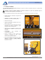
Consultare attentamente questo manuale
prima di utilizzare la macchina, la sua conoscenza
è indispensabile per l’utilizzo in sicurezza,
va conservato per tutta la durata della macchina.
Vi ringraziamo per la scelta fatta, avete acquistato un prodotto di ottima qualità,garantito
da una decennale esperienza.
Ogni macchina prima di uscire dalla fabbrica viene accuratamente ispezionata per
garantirla da ogni difetto.Nell’eventualità che si manifesti ugualmente qualche difetto di
materiale interpellate subito il vostro concessionario.
Con l’obiettivo di migliorare costantemente il prodotto e di mantenerlo ai massimi livelli
siamo a vostra disposizione per fornirvi ogni chiarimento o informazione.
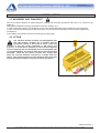
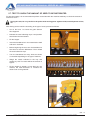
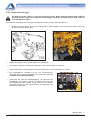
FATE ATTENZIONE AL TRIANGOLO, INDICA PERICOLO
LA DEFINIZIONE MACCHINA , SOSTITUISCE LA DENOMINAZIONE COMMERCIALE
A CUI FA RIFERIMENTO IL MANUALE IN OGGETTO
Le illustrazioni riportate nel presente manuale hanno valore puramente indicativo.
Possono pertanto presentare delle piccole differenze che sono ininfluenti per le istruzioni
riportate nel manuale stesso
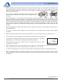
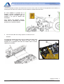
N.B. : Vista convenzionale della macchina normalmente la ditta ALPEGO
considera la macchina vista da dietro rispetto al senso di marcia;
questo per poter individuare i particolari e le corrette posizioni di
montaggio che devono essere rispettate per i pezzi che riportano nella
descrizione “ destro o sinistro”. (Es.: cardano destro o sinistro, zappa
destra o sinistra ecc.)
3
Copyright ©2009 della Alpego spa ® -Tutti i diritti sono riservati. È espressamente vietata la ristampa o l’uso non autorizzato per iscritto da parte di Alpego spa
Sommario
1. INFORMAZIONI GENERALI ..................................................................................................................................... 1 1.1. SCOPO DEL MANUALE ...................................................................................................................................... 1 1.2. DOCUMENTAZIONE ALLEGATA ALLA MACCHINA ......................................................................................... 1
1.3. GARANZIA ........................................................................................................................................................... 1 1.4. IDENTIFICAZIONE DELLA MACCHINA ............................................................................................................ 1 2. SPECIFICHE TECNICHE ........................................................................................................................................... 2 2.1. DESCRIZIONE DELLA MACCHINA .................................................................................................................... 2 2.2. COMPONENTI SEMINATRICE ........................................................................................................................... 2 2.3. DATI TECNICI ...................................................................................................................................................... 3 2.3.1. Tabella dati tecnici M2 ................................................................................................................................... 3 2.3.2. Tabella dati tecnici M2S ................................................................................................................................. 3 2.4. LIVELLO SONORO .............................................................................................................................................. 3 3. NORME DI SICUREZZA ............................................................................................................................................ 4 3.1. USO IN SICUREZZA ........................................................................................................................................... 4 3.2. MANUTENZIONE IN SICUREZZA ..................................................................................................................... 6 3.3. CIRCOLAZIONE STRADALE .............................................................................................................................. 6 3.4. ABBIGLIAMENTO ................................................................................................................................................ 6 3.5. ECOLOGIA........................................................................................................................................................... 6 3.6. SEGNALI DI SICUREZZA.................................................................................................................................... 7 4. INSTALLAZIONE ....................................................................................................................................................... 9 4.1. MOVIMENTAZIONE E TRASPORTO ................................................................................................................. 9 4.2. SOLLEVAMENTO DELLA MACCHINA ............................................................................................................... 9
4.3. INSTALLAZIONE DELLA SEMINATRICE ......................................................................................................... 10 4.3.1. Montaggio dei componenti ........................................................................................................................... 10 4.3.2. Applicazione su erpice ................................................................................................................................. 12 4.4. VERIFICA DI CAPACITÀ DI SOLLEVAMENTO E STABILITÀ DELLA TRATTRICE ...................................... 13
5. ISTRUZIONI PER L’USO ......................................................................................................................................... 15 5.1. AVVIAMENTO DELLA MACCHINA ................................................................................................................... 15 5.2. PREPARATIVI PER LA SEMINA ....................................................................................................................... 15 5.3. RIFORNIMENTO SERBATOIO ......................................................................................................................... 16 5.4. SCARICO SERBATOIO SEME.......................................................................................................................... 16 5.5. REGOLAZIONE ORGANI DI DISTRIBUZIONE ................................................................................................ 16 5.5.1. Regolazione tastatori ................................................................................................................................... 16 5.5.2. Regolazione rulli dosatori ............................................................................................................................. 17 5.5.3. Regolazione lamine ...................................................................................................................................... 17 5.6. LETTURA TABELLA DI SEMINA ...................................................................................................................... 18 5.7. PROVA DI SEMINA ........................................................................................................................................... 19 5.8. ESCLUSIONE DI SEMINA MEZZA MACCHINA ............................................................................................... 20 5.9. REGOLAZIONE DISTANZA INTERFILA ........................................................................................................... 20 5.10. REGOLAZIONE DELLA PROFONDITÀ DI SEMINA ...................................................................................... 21 5.10.1. Regolazione profondità M2 ........................................................................................................................ 21 5.10.2. Regolazione profondità su M2S ................................................................................................................. 21 5.11. REGOLAZIONE ASSOLCATORI .................................................................................................................... 22 5.11.1. Regolazione assolcatore a zappetta (standard) ........................................................................................ 22
5.11.2. Regolazione assolcatore a disco (optional) ............................................................................................... 22
5.12. REGOLAZIONE ERPICE COPRISEME .......................................................................................................... 23 5.12.1. Regolazione erpice copriseme per M2 ...................................................................................................... 23 5.12.2. Regolazione erpice copriseme per M2S .................................................................................................... 23 Copyright ©2009 della Alpego srl ® -Tutti i diritti sono riservati. È espressamente vietata la ristampa o l’uso non autorizzato per iscritto da parte di Alpego srl
MANUALE SEMINATRICE MECCANICA M2 - M2S
Old Cod.Q00A00138
New Cod. MANT2010/00435 R.0
6. MANUTENZIONE ..................................................................................................................................................... 24 6.1. VERIFICHE E CONTROLLI ............................................................................................................................... 24 6.2. MESSA A RIPOSO ............................................................................................................................................ 24 7. ACCESSORI............................................................................................................................................................. 24 Copyright ©2009 della Alpego srl ® -Tutti i diritti sono riservati. È espressamente vietata la ristampa o l’uso non autorizzato per iscritto da parte di Alpego srl
MANUALE SEMINATRICE MECCANICA M2 - M2S
Old Cod.Q00A00138
New Cod. MANT2010/00435 R.0
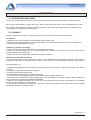
1. INFORMAZIONI GENERALI
1.1. SCOPO DEL MANUALE
Questo manuale e’ stato redatto dal costruttore della macchina e fa parte integrante della documentazione allegata alla macchina
Il manuale definisce lo scopo per cui e’ stata costruita la macchina , ne stabilisce la corretta applicazione e i limiti di utilizzazione.
La costante applicazione delle indicazioni riportate in questo manuale garantisce la sicurezza delle persone che utilizzano la
macchina, l’economia di esercizio e una più’ lunga durata della macchina.
Il presente manuale e’ stato suddiviso in vari paragrafi , per facilitare la ricerca degli argomenti, consultare l’indice iniziale.
Le illustrazioni riportate nel presente manuale sono fornite a titolo esemplificativo anche se sono sensibilmente differenti dalla
macchina in vostro possesso, la sicurezza e le informazioni sono comunque garantite.
1.2. DOCUMENTAZIONE ALLEGATA ALLA MACCHINA
Con la macchina deve essere allegata la seguente documentazione:
•
•
•
Manuale uso e manutenzione
Dichiarazione CE di conformità
Catalogo ricambi
La macchina può essere fornita di diversi accessori / allestimenti. Per l’istallazione e l’uso di questi far riferimento ai relativi
manuale forniti assieme alla documentazione della macchina.
COD.
Q00A00119
Q00A00132
D12339
DESCRIZIONE
Manuale uso e manutenzione dischi segnafile
Manuale uso e manutenzione pettine copriseme
Manuale uso e manutenzione computer “Plus”
1.3. GARANZIA
Controllare all’atto della consegna che la macchina e gli eventuali accessori non abbiano subito danni durante il trasporto.
Eventuali reclami devono essere presentati per iscritto entro 6 giorni.
DECADENZA DELLA GARANZIA
La garanzia decade immediatamente:
•
•
•
•
•
•
qualora si dovesse verificare un errore di manovra
per insufficiente manutenzione della frizione dell’albero cardanico
qualora si dovesse oltrepassare il limite di potenza consentito (vedi tabella 2.2)
qualora non fossero seguite le istruzioni descritte nel presente manuale
qualora non fossero usati ricambi originali
qualora venisse apportata qualsiasi modifica senza autorizzazione del costruttore
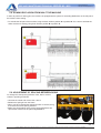
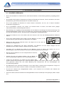
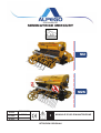
1.4. IDENTIFICAZIONE DELLA MACCHINA
In corrispondenza dei 3 punti di attacco alla trattrice e’ fissata la targhetta di identificazione della macchina che riporta i seguenti
dati:
1. Modello della macchina
2. Numero di matricola
3. Peso massimo della macchina con rullo
4. Anno di costruzione
Il peso indicato è relativo alla macchina completa del rullo più pesante senza
accessori.
INFORMAZIONI GENERALI - 1
Copyright ©2009 della Alpego srl ® -Tutti i diritti sono riservati. È espressamente vietata la ristampa o l’uso non autorizzato per iscritto da parte di Alpego spa
MANUALE SEMINATRICE MECCANICA M2 - M2S
Old Cod.Q00A00138
New Cod. MANT2010/00435 R.0
2. SPECIFICHE TECNICHE
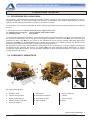
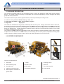
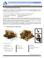
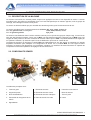
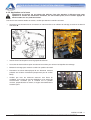
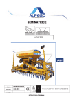
2.1. DESCRIZIONE DELLA MACCHINA
La macchina è sostanzialmente costituita da un telaio portante, al quale vi sono applicati la tramoggia dei semi e i
dispositivi di semina. La seminatrice è adatta ad operare in combinazione ad un erpice trasportato da un trattore
agricolo, munito di gruppo sollevatore, con attacco universale a tre punti.
La seminatrice è una macchina destinata ad essere utilizzata esclusivamente per lavorazioni agricole, per la semina
su terra.
E’ idonea per la semina di cereali: Frumento, orzo, segala, avena, riso
Per sementi fine e foraggiere: Colza, trifoglio, erba medica, loglio
Per sementi grosse:
Soia, piselli
Le sementi sono distribuite nel terreno in modo continuo quindi non per seme singolo, ma da un rullo a denti per ogni
fila, perché sono depositate nel terreno per mezzo d’organi assolcatori a falcione nella M2 F; per mezzo d’organi
assolcatori a disco nella M2 D e per mezzo di una rastrelliera di tubi di semina montata sulla barra affinamento
dell'erpice nella M2S. Le quantità distribuite sono regolate da un sistema con variatore (cambio), che prende il moto
della ruota di trasmissione che è posta in rotazione per aderenza al terreno.
Gli assolcatori presenti nella versione M2 sono indipendenti tra loro e permettono un ampio margine d’oscillazione
per adeguarsi alla superficie del terreno; nel modello M2S una volta registrata la barra affinamento, la semina
mantiene una profondità costante. Un solo operatore sistemato sul posto di guida del trattore è in grado di compiere
le varie operazioni di semina.
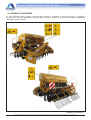
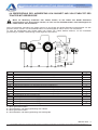
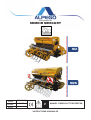
2.2. COMPONENTI SEMINATRICE
Gli organi principali sono:
1. Serbatoio semi
6. Assolcatore
7. Erpice copriseme
2. Vasche raccogli seme
6A. Assolcatore a falcione
8. Cambio
3. Ruota di trasmissione
6B. Assolcatore a disco
9. Tirante 3° punto
4. Pedana di carico serbatoio
6C. Barra a spagio
10. Erpice
5. Kit luci di trasporto
SPECIFICHE TECNICHE - 2
Copyright ©2009 della Alpego srl ® -Tutti i diritti sono riservati. È espressamente vietata la ristampa o l’uso non autorizzato per iscritto da parte di Alpego spa
MANUALE SEMINATRICE MECCANICA M2 - M2S
Old Cod.Q00A00138
New Cod. MANT2010/00435 R.0
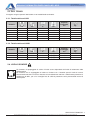
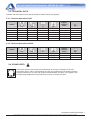
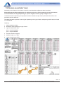
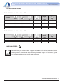
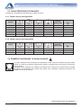
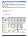
2.3. DATI TECNICI
Di seguito vengono riportati i dati relativi ai vari modelli delle seminatrici.
2.3.1. Tabella dati tecnici M2
modello
M2-300 F
M2-300 D
M2-350 F
M2-350 D
M2-400 F
M2-400 D
cm.
300
300
350
350
400
400
cm.
300
300
350
350
400
400
n°
24
24
28
28
32
32
cm.
12.5
12.5
12.5
12.5
12.5
12.5
Capacità
Tramoggia
litri
Kg.
700
700
700
700
700
700
?
?
?
?
?
?
Capacità
Tramoggia
litri
Kg.
700
700
700
?
?
?
2.3.2. Tabella dati tecnici M2S
modello
M2S-300
M2S-350
M2S-400
cm.
300
350
400
cm.
300
350
400
n°
24
28
32
cm.
spaglio
spaglio
spaglio
2.4. LIVELLO SONORO
Se il trattore è equipaggiato di cabina il livello sonoro dipenderà dal livello di isolamento della
cabina stessa.
Se il trattore non è equipaggiato di cabina o funziona con i finestrini aperti il livello di rumore
emesso dalla macchina in lavoro misurato ad una distanza di 200 mm. dalla finestra posteriore è
superiore a 85 dBa , per cui si consiglia l’uso di cuffie di protezione come previsto dalle norme di
diversi paesi.
SPECIFICHE TECNICHE - 3
Copyright ©2009 della Alpego srl ® -Tutti i diritti sono riservati. È espressamente vietata la ristampa o l’uso non autorizzato per iscritto da parte di Alpego spa
MANUALE SEMINATRICE MECCANICA M2 - M2S
Old Cod.Q00A00138
New Cod. MANT2010/00435 R.0
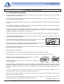
3. NORME DI SICUREZZA
3.1. USO IN SICUREZZA
•
Leggere attentamente i manuali per l’uso e la manutenzione prima di procedere alle operazioni di avviamento ,
uso e manutenzione della attrezzatura.
•
Il costruttore declina ogni responsabilita’ per danni a persone , animali o cose causati dalla inosservanza delle
norme di sicurezza.
•
E’ assolutamente vietato utilizzare la macchina per un uso diverso da quello espressamente indicato in questo
libretto.
•
Evitare assolutamente di toccare in qualsiasi modo le parti in movimento.
•
La macchina ed i suoi eventuali accessori per il trasporto su strada devono essere muniti di segnalazioni e
protezioni adeguate.
•
•
E assolutamente vietato condurre o far condurre il trattore da personale non in possesso di patente di guida
adeguata, inesperto e non in buone condizioni di salute.
•
Esaminare attentamente le etichette adesive riportate sulla macchina e rispettare le indicazioni in esse
contenute. Le decalcomanie relative alla sicurezza devono essere sempre ben evidenti:vanno tenute pulite e
vanno sostituite se diventano poco leggibili (eventualmente possono essere rìchieste al concessionario).
•
Durante le manovre non permettere l’avvicinamento di persone o animali al raggio di azione della macchina
•
Durante il lavoro non permettere l’avvicinamento di persone, animali e cose al
raggio di azione delle zolle e delle pietre proiettate dalla macchina.
•
E’ assolutamente vietato intromettersi nella zona tra il trattore e la macchina per
azionare i comandi esterni del sollevatore idraulico.
•
Rimanere sempre seduti sul posto di guida della trattrice e scendere solamente quando la presa di forza della
trattrice è disinserita e il freno di stazionamento della trattrice e’ inserito
•
Durante le pause di lavoro disinserire la presa di forza ,spegnere il motore, appoggiare la macchina sul terreno e
inserire il freno di stazionamento del trattore.
•
Non lavorare con protezioni rimosse.
•
Non utilizzare la macchina come mezzo di trasporto di persone animali o cose.
•
Non lavorare su terreni o luoghi che possono compromettere la stabilità della macchina.
•
Conoscere bene l’area in cui si sta lavorando. Non operare mai in un area in cui vi siano ostacoli come pietre
bastoni o radici in quanto rovinerebbero l’integrità della macchina.
•
Per il trasporto su strada usare sempre il lampeggiante di pericolo.
•
Per la circolazione su strada rispettare le norme vigenti nel proprio paese. E’ molto importante ricordare che la
tenuta di strada , la capacità di frenatura e la direzione sono influenzati dal peso della macchina applicata al
sollevatore del trattore; nelle curve inoltre considerare l’azione della forza centrifuga che sposta il baricentro
della macchina
NORME DI SICUREZZA - 4
Copyright ©2009 della Alpego srl ® -Tutti i diritti sono riservati. È espressamente vietata la ristampa o l’uso non autorizzato per iscritto da parte di Alpego spa
MANUALE SEMINATRICE MECCANICA M2 - M2S
Old Cod.Q00A00138
New Cod. MANT2010/00435 R.0
•
Non utilizzare la macchina all’interno di strutture chiuse a meno che non vi sia una adeguata ventilazione
•
Evitare di far girare a vuoto (fuori del terreno) la macchina.
Durante il lavoro evitare di effettuare curve con la macchina
interrata, ne tanto meno lavorare in retromarcia. SolIevarla
sempre per i cambiamenti di direzione e le inversioni di
marcia.
•
Durante il trasporto, od ogni qualvolta si renda necessario il sollevamento della macchina, è opportuno che il
gruppo di sollevamento del trattore venga regolato in modo che la macchina stessa non sia sollevata da terra
per più di 35 cm circa. Evitare di immettersi su strade pubbliche con la macchina sporca di terra, erba o altro che
produca sporcizia ed intralcio al traffico stradale. Non far cadere con violenza la macchina sul terreno ma farla
scendere lentamente per consentire il graduale inserimento delle lame nel terreno. In caso contrario si
provocherebbero forti sollecitazioni su tutti i componenti della macchina stessa che potrebbero comprometterne
la loro integrità.
•
In fase di trasporto su strada,con la macchina sollevata, mettere in posizione dl blocco la leva d comando del
sollevatore idraulico del trattore.
•
Utilizzare solamente l’albero cardanico previsto dal costruttore, dotato delle sicurezze contro i sovraccarichi.
•
Prima di inserire la presa di forza, accertarsi del numero di giri prestabilito. Non scambiare Il regime di 540
giri/min con 1000 g/min.
•
L’installazione e lo smontaggio del albero cardanico deve essere sempre fatta a motore spento.
•
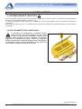
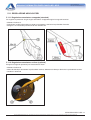
La protezione dell’albero cardanico deve essere sempre efficiente, va controllata
periodicamente , e fissata con le catenelle per impedirne la rotazione.
•
Disinserire sempre la Presa di Forza quando l’albero cardanico fa un angolo
superiore ai 15°, vedi figura.
•
Prima di inserire la presa di forza assicurarsi che non vi siano persone o animali nella zona d’azione e che il
regime scelto corrisponda a quello consentito. Mai superare il massimo previsto
•
Per evitare scottature non toccare il cambio di velocità dopo un uso prolungato della macchina.
•
Prima di effettuare la sostituzione degli ingranaggi nel cambio di velocità disinserire la presa di forza, inserire il
freno di stazionamento e togliere la chiave di avviamento, quindi rimontare il coperchio del cambio prima di
riavviare la macchina.
NORME DI SICUREZZA - 5
Copyright ©2009 della Alpego srl ® -Tutti i diritti sono riservati. È espressamente vietata la ristampa o l’uso non autorizzato per iscritto da parte di Alpego spa
MANUALE SEMINATRICE MECCANICA M2 - M2S
Old Cod.Q00A00138
New Cod. MANT2010/00435 R.0
3.2. MANUTENZIONE IN SICUREZZA
•
Non permettere a persone non autorizzate di effettuare operazioni di manutenzione o di fare qualsiasi altro tipo
di intervento sulla macchina.
•
La manutenzione e le riparazioni vanno effettuate in officine opportunamente attrezzate.
•
In caso di manutenzione della macchina disinnestare i tubi idraulici dalle prese del trattore.
•
Utilizzare sempre accessori e ricambi originali per rispettare le esigenze richieste dal costruttore in caso
contrario oltre a decadere la garanzia si possono causare anomalie di funzionamento che pregiudicano la
sicurezza della macchina.
•
Rispettare la conformità degli olii consigliati.
•
Nell’effettuare qualsiasi operazione sulla macchina disinserire la presa di forza della trattrice, inserire il freno di
stazionamento togliere la chiave di avviamento e fare attenzione che altre persone non salgano sulla trattrice.
•
Prima di pulire e ingrassare l’albero cardanico disinserire la Presa di Forza ,spegnere il motore, inserire il freno
di stazionamento e togliere la chiave di avviamento
3.3. CIRCOLAZIONE STRADALE
Se necessario la macchina può essere trasportata su strada agganciata al trattore; l’operatore deve verificare,
confrontare ed adeguare l’attrezzatura per il pieno rispetto delle Norme del Codice della Strada nel paese di utilizzo.
Si deve tenere presente in particolar modo:
1. per l’aggancio della macchina al trattore è necessario seguire le istruzioni riportate nel presente manuale
2. durante il trasporto è necessario mantenere la macchina bloccata e sollevata da terra
3. obbligo del rispetto delle norme per la salvaguardia della propia incolumità e quella degli altri, adottando tutte le
precauzioni possibili.
4. devono essere previste le protezioni per gli elementi sporgenti e fuori sagoma
5. l’intera attrezzatura deve essere equipaggiata di appropiato impianto di illuminazione con elementi di
segnalazione e lampeggiante
6. dove previsti, devono essere applicati i cartelli di segnalazione della sagoma
7. la capacità di frenatura e la direzione sono influenzati dal peso della macchina applicata al sollevatore del
trattore; nelle curve inoltre considerare l’azione della forza centrifuga che sposta il baricentro della macchina.
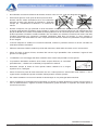
3.4. ABBIGLIAMENTO
Indossare sempre indumenti che proteggano il corpo senza parti penzolanti che potrebbero impigliarsi su
componenti in movimento, togliere inoltre orologi, anelli collane ecc. che potrebbero rappresentare lo stesso
pericolo. Raccogliere i capelli lunghi.
Se richiesto dalle normative vigenti nel proprio paese l’utilizzatore della
macchina dovrà indossare idonei mezzi di protezione :(occhiali, guanti
casco, scarpe, ecc.)
3.5. ECOLOGIA
Rispettare le leggi in vigore nel proprio paese relativamente all’uso ed allo smaltimento dei prodotti impiegati per la
lubrificazione , la manutenzione e la pulizia della macchina; osservare attentamente le indicazioni riportate sulle
confezioni dei prodotti stessi.
Rispettare le norme in vigore anche in caso di rottamazione della macchina.
NORME DI SICUREZZA - 6
Copyright ©2009 della Alpego srl ® -Tutti i diritti sono riservati. È espressamente vietata la ristampa o l’uso non autorizzato per iscritto da parte di Alpego spa
MANUALE SEMINATRICE MECCANICA M2 - M2S
Old Cod.Q00A00138
New Cod. MANT2010/00435 R.0
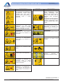
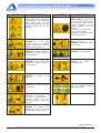
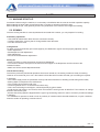
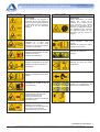
3.6. SEGNALI DI SICUREZZA
Le varie etichette adesive presenti sulla macchina servono a segnalare la fonte del pericolo , osservatele
attentamente e seguite le indicazioni per l’utilizzo della macchina in sicurezza., vanno mantenute pulite e leggibili se
danneggiate vanno sostituite
NORME DI SICUREZZA - 7
Copyright ©2009 della Alpego srl ® -Tutti i diritti sono riservati. È espressamente vietata la ristampa o l’uso non autorizzato per iscritto da parte di Alpego spa
MANUALE SEMINATRICE MECCANICA M2 - M2S
FIGURA
INDICAZIONI
FIGURA
Old Cod.Q00A00138
New Cod. MANT2010/00435 R.0
INDICAZIONI
ATTENZIONE
Le operazioni di regolazione e
manutenzione devono essere
eseguite dopo aver letto il
manuale d’uso e manutenzione, a
macchina
ferma
e
chiave
disinserita.
ATTENZIONE
ZONA RUMOROSA questo
segnale contrassegna zone
della macchina dove il livello di
rumore può essere tale da
provocare danni all’apparato
uditivo.
In presenza di questo segnale è
obbligatorio l’uso di dispositivi di
protezione dell’apparato uditivo
del tipo prescritto dalle norme
vigenti
ATTENZIONE
PERICOLO
di
fluidi
sotto
pressione. Leggere il manuale
prima di intervenire ed in caso di
ferimento consultare un medico.
ATTENZIONE
Limite massimo di giri al minuto.
PERICOLO di contatto con
l’albero cardanico in movimento
ATTENZIONE
PERICOLO di schiacciamento.
Non sostare tra la trattrice e la
macchina.
ATTENZIONE
PERICOLO di sostanze tossiche
ATTENZIONE
PERICOLO di schiacciamento.
Non sostare tra la trattrice e la
macchina
ATTENZIONE
ATTENZIONE
PERICOLO di cesoiamento delle
mani
PUNTO DI SOLLEVAMENTO
ATTENZIONE.
Vietato salire o farsi trasportare
ATTENZIONE
ATTENZIONE.
Cinematismi in movimento. Se
avvicinate senza le dovute
precauzioni comportano un alto
rischio di infortunio.
PUNTI DI INGRASSAGGIO
PERICOLO di cadute di parti
sospese.
Utilizzare
i
Dispositivi
di
Protezione Individuale richiesti
ATTENZIONE
PERICOLO di impigliamento e
trascinamento. Non avvicinare le
mani all’albero di trasmissione in
moto.
NORME DI SICUREZZA - 8
Copyright ©2009 della Alpego srl ® -Tutti i diritti sono riservati. È espressamente vietata la ristampa o l’uso non autorizzato per iscritto da parte di Alpego spa
MANUALE SEMINATRICE MECCANICA M2 - M2S
Old Cod.Q00A00138
New Cod. MANT2010/00435 R.0
4. INSTALLAZIONE
4.1. MOVIMENTAZIONE E TRASPORTO
Porre la massima attenzione alla sicurezza durante le operazioni di carico e scarico, che dovranno essere effettuare
da personale qualificato(imbracatori, carrellisti, etc.)
In caso di sollevamento della macchina, è obbligatorio servirsi degli appositi punti di sollevamento indicati dai
pittogrammi.
Per il trasporto della macchina, si deve utilizzare un automezzo di potenza e dimensioni adeguate, opportunamente
predisposto.
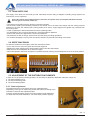
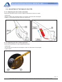
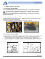
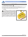
4.2. SOLLEVAMENTO DELLA MACCHINA
Le operazioni di sollevamento e trasporto devono
essere eseguiti con mezzi adeguati al peso della
macchina e da personale addestrato a questo tipo di
manovre. Nella necessità di dover sollevare la macchina
agganciare la seminatrice nei punti indicati con l’apposito
adesivo utilizzando un nastro omologato per non danneggiare
la tramoggia. Durante questa operazione la macchina non
dovrà essere sollevata più di 200 mm dal suolo.
INSTALLAZIONE - 9
Copyright ©2009 della Alpego srl ® -Tutti i diritti sono riservati. È espressamente vietata la ristampa o l’uso non autorizzato per iscritto da parte di Alpego spa
MANUALE SEMINATRICE MECCANICA M2 - M2S
Old Cod.Q00A00138
New Cod. MANT2010/00435 R.0
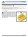
4.3. INSTALLAZIONE DELLA SEMINATRICE
Tutte le operazioni di regolazione e di
preparazione al lavoro, devono essere
eseguite con il trattore spento, la chiave
disinserita e la seminatrice stabilmente appoggiata
a terra sulle proprie gambe di sostegno.
Per applicare la seminatrice M2 su erpice sono
necessari questi componenti di montaggio:
• I bracci di attacco seminatrice 1
• Le staffe di aggancio rapido con rullo 2
• Il tirante per terzo punto 3.
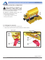
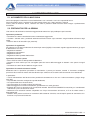
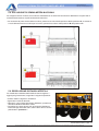
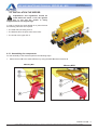
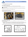
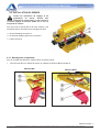
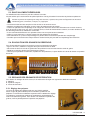
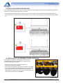
4.3.1. Montaggio dei componenti
Per il montaggio dei componenti seguire i seguenti punti:
1. Fissare i bracci A al telaio della seminatrice utilizzando le viti B e le staffe C
Mercury M2
Mercury M2S
INSTALLAZIONE - 10
Copyright ©2009 della Alpego srl ® -Tutti i diritti sono riservati. È espressamente vietata la ristampa o l’uso non autorizzato per iscritto da parte di Alpego spa
MANUALE SEMINATRICE MECCANICA M2 - M2S
Old Cod.Q00A00138
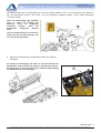
New Cod. MANT2010/00435 R.0
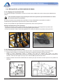
I fori standard di fissaggio del braccio A sono quelli centrali, ma a seconda degli allestimenti della macchina la
seminatrice può essere avvicinata o allontanata dall’erpice utilizzando gli altri fori.
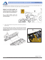
Se si modifica la posizione di fissaggio
correggere
l’inclinazione
della
macchina con il tirante terzo punto in
modo che la seminatrice lavori in
posizione orizzontale.
Per una posizione corretta auitarsi con
l’indicatore presente su un fianco del
serbatoio.
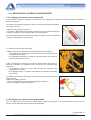
2. Fissare le staffe D di aggancio rapido al rullo tramite cavallotti E.
La larghezza di fissaggio dei bracci A sul telaio della
seminatrice dovrà corrispondere alla larghezza delle staffe D.
Essa
varia a seconda della posizione delle lame rullo
dell’erpice.
INSTALLAZIONE - 11
Copyright ©2009 della Alpego srl ® -Tutti i diritti sono riservati. È espressamente vietata la ristampa o l’uso non autorizzato per iscritto da parte di Alpego spa
MANUALE SEMINATRICE MECCANICA M2 - M2S
Old Cod.Q00A00138
New Cod. MANT2010/00435 R.0
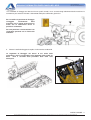
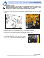
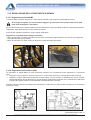
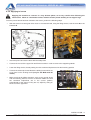
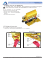
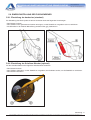
4.3.2. Applicazione su erpice
L’applicazione al trattore è una fase molto delicata. Fare molta attenzione ad effettuare l’intera
operazione seguendo le seguenti istruzioni. L’operazione deve essere eseguita su un piano
orizzontale, con la seminatrice posta stabilmente sulle proprie gambe di sostegno
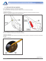
Agganciato l’erpice al trattore procedere nel modo seguente:
•
Avvicinarsi con la trattrice alla seminatrice in retromarcia ed, utilizzando il sollevatore, agganciare i bracci A alle
staffe B
•
Inserire i perni C e bloccarli con le spine di sicurezza
•
Collegare il tirante terzo punto e sollevare la macchina per rimuovere le gambe di appoggio
•
Abbassare il sollevatore mettendo le attrezzature così combinate in posizione di lavoro.
•
Collegare i tubi telescopici D ai tubi di semina presenti sulla
barra affinamento E (solo per seminatrice M2S)
•
Verificare che tutti gli organi seminanti siano liberi di oscillare,
come la ruota di semina e l’erpice copriseme. Controllare che
l’attrezzatura sia in posizione corretta, perpendicolare al terreno,
eventualmente agire sul tirante terzo punto.
INSTALLAZIONE - 12
Copyright ©2009 della Alpego srl ® -Tutti i diritti sono riservati. È espressamente vietata la ristampa o l’uso non autorizzato per iscritto da parte di Alpego spa
MANUALE SEMINATRICE MECCANICA M2 - M2S
Old Cod.Q00A00138
New Cod. MANT2010/00435 R.0
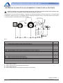
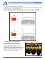
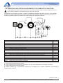
4.4. VERIFICA DI CAPACITÀ DI SOLLEVAMENTO E STABILITÀ DELLA TRATTRICE
Quando un attrezzo viene accoppiato al trattore, divenendo ai fini della circolazione stradale parte integrante dello
stesso, può alterarne la stabilità e causare difficoltà nella guida e nel lavoro.
L’applicazione di una macchina al trattore, comporta una diversa distribuzione dei pesi sugli assi. A seconda della
composizione della macchina è consigliabile pertanto aggiungere apposite zavorre nella parte anteriore del trattore
in modo da ripartire adeguatamente il peso sugli assi.
dove:
A
= distanza dell’asse anteriore dalle zavorre anteriori (m)
B
= interasse ruote trattore (m)
2
C
= distanza dell’asse posteriore all’ attacco inferiore attrezzatura (m)
2
Gv
= massa della zavorra (Kg)
3
Te
= Massa del trattore a vuoto
Tv
= Carico sul asse anteriore del trattore a vuoto
2
2
Th
= Carico sul asse posteriore del trattore a vuoto
Lb tot = distanza dall attacco inferiore al baricentro dell attrezzatura combinata completa (m)
2
3
Lb1
= distanza dall attacco inferiore al baricentro della prima macchina combinata (m)
1
Lb2
= distanza dall attacco inferiore al baricentro della seconda macchina combinata (m)
1
Lb3
= distanza dall attacco inferiore al baricentro della terza macchina combinata (m)
1
Lb4
= distanza dall attacco inferiore al baricentro della terza macchina combinata (m)
1
Mb1
= Massa complessiva della prima attrezzatura (kg)
4
Mb2
= Massa complessiva della seconda attrezzatura (kg)
4
Mb3
= Massa complessiva della terza attrezzatura (kg)
4
Mb4
= Massa complessiva della quarta attrezzatura (kg)
4
2
Mb tot = Massa complessiva totale dell intera macchina combinata
1 = deve essere misurato
2 = vedere manuale uso e manutenzione del trattore
3 = deve essere calcolato
4 = vedere manuale uso e manutenzione accessorio da combinare
INSTALLAZIONE - 13
Copyright ©2009 della Alpego srl ® -Tutti i diritti sono riservati. È espressamente vietata la ristampa o l’uso non autorizzato per iscritto da parte di Alpego spa
MANUALE SEMINATRICE MECCANICA M2 - M2S
Old Cod.Q00A00138
New Cod. MANT2010/00435 R.0
La zavorra da applicare si calcola con la seguente formula:
Gv min. = (Mb tot x (C + Lb tot)) – (Tv x B) + (0,2 x Te x B)
----------------------------------------------------------------A+B
Per determinare la distanza del baricentro della macchina combinata all attacco trattore inferiore la si calcola con la
seguente formula:
Lb tot = (Lb1 x Mb1) + (Lb2 x Mb2) + (Lb3 x Mb3) + (Lb4 x Mb4) + (Lb….x Mb….)
-----------------------------------------------------------------------------------------------------Mb1+Mb2+Mb3+Mb4+Mb….
La massa complessiva totale dell’intera macchina combinta la si calcola con la seguente formula
Mb tot = Mb1+Mb2+Mb3+Mb4+Mb…..
Sul ponte anteriore del trattore deve, in ogni
caso, gravare almeno il 20% della massa
complessiva trattore-attrezzo in ordine di marcia.
È comunque da tenere presente che, oltre
all’appropriata scelta dell’accoppiamento trattoreattrezzo, l’applicazione di zavorre in posizione
anteriore, nei limiti e con le modalità indicate dal
costruttore del trattore, può migliorarne la
stabilità. Inoltre, con trattore fermo si deve far
scendere a terra l’attrezzo evitando così possibili
discese
involontarie,
migliorandone,
nel
contempo, la stabilità.
Interasse ruote trattore
B
=………… m
Distanza dell’asse anteriore
dalle zavorre anteriori
A
=………… m
Massa del trattore
Te
=……………Kg
Massa della zavorra
Gv
=……………Kg
Carico sul asse anteriore del
trattore a vuoto
Tv
=……...
Kg
Massa dell’attrezzatura
Mb tot =……...
Kg
Lunghezza baricentro tot
Lb tot =…………….m
INSTALLAZIONE - 14
Copyright ©2009 della Alpego srl ® -Tutti i diritti sono riservati. È espressamente vietata la ristampa o l’uso non autorizzato per iscritto da parte di Alpego spa
MANUALE SEMINATRICE MECCANICA M2 - M2S
Old Cod.Q00A00138
New Cod. MANT2010/00435 R.0
5. ISTRUZIONI PER L’USO
5.1. AVVIAMENTO DELLA MACCHINA
Prima di impiegare la macchina occorre familiarizzare con i comandi e con le sue capacità di lavoro.
Prima di iniziare il lavoro, assicurarsi che nella zona d’azione non vi siano persone o animali.
Inoltre, prima di iniziare il lavoro, verificare che tutte le protezioni della macchina siano integre e perfettamente
funzionanti.
5.2. PREPARATIVI PER LA SEMINA
Una volta che la seminatrice risulta ben agganciata al trattore la si può predisporre per la semina.
Operazioni preliminari
• Controllare che tutte le trasmissioni siano correttamente agganciate.
• Caricare i serbatoi seme, prestando attenzione affinché nessun corpo estraneo venga introdotto all’interno degli
stessi.
• Liberare i bracci del tracciafi le (se presente).
Operazioni di regolazione
Per ottenere un corretto investimento di sementi per ettaro (Kg/Ha) è necessario regolare opportunamente gli organi
di distribuzione che sono:
• Regolazione tastatori.
• Regolazione rulli dosatori.
• Regolazione lamine.
• Regolazione della quantità distribuzione.
Operazioni di messa a punto
• Fare il TEST di verifi ca della quantità da distribuire.
• Ruotare la ruota motrice per far convogliare parte del seme dalla tramoggia ai dosatori e da questi ai singoli
falcioni.
• Controllare che tutti i falcioni abbiano erogato i semi.
Operazioni di controllo durante la semina
Effettuate tutte le operazioni precedenti la seminatrice è pronta per lavorare, tuttavia è vivamente consigliato
percorrere alcuni metri di marcia nelle due direzioni per verificare che la semina stia avvenendo come desiderato.
In particolare:
• I tubi di alimentazione del falcione siano posizionati correttamente e che non vi siano strozzature o pieghe lungo
tutti i tubi;
• La profondità di semina corrisponda a quella desiderata;
• La copertura del seme sia suffi ciente;
• La ruota motrice giri in modo continuo ed uniforme;
• Nella tramoggia non si formino intasamenti, specialmente con semi glumacei.
• Evitate di fare curve e retromarce con la macchina interrata. SOLLEVATE SEMPRE la macchina per i cambiamenti
di direzione e per le inversioni di marcia.
• Mantenere una velocità di semina compatibile con il tipo di lavorazione del terreno, al fi ne di evitare rotture o
danneggiamenti.
• Nessuno deve potersi avvicinare ai contenitori delle sostanze chimiche, nonché aprirli quando la seminatrice è in
funzione o in procinto di funzionare.
ISTRUZIONI PER L’USO - 15
Copyright ©2009 della Alpego srl ® -Tutti i diritti sono riservati. È espressamente vietata la ristampa o l’uso non autorizzato per iscritto da parte di Alpego spa
MANUALE SEMINATRICE MECCANICA M2 - M2S
Old Cod.Q00A00138
New Cod. MANT2010/00435 R.0
5.3. RIFORNIMENTO SERBATOIO
Il rifornimento del serbatoio può essere effettuato a mano.
Ricordare che il sollevamento di pesi superiori a 30 kg richiede l’intervento di più operatori.
Durante le fasi di carico e scarico serbatoi, l’operatore deve utilizzare adeguati Dispositivi di Protezione
individuale (guanti, tuta, mascherine, ecc.).
• I serbatoi vanno riempiti una volta giunti sul terreno da seminare.
• Prima di rifornire il serbatoio, seguire le indicazioni per calcolare la zavorra anteriore minima da applicare al
trattore, in modo da assicurare la stabilità necessaria al complesso trattrice-seminatrice.
• Abbassare completamente il sollevatore ed azionare il freno di stazionamento del trattore.
• Tutte le operazioni di carico e scarico dei serbatoi vanno eseguite sul terreno da seminare, con la seminatrice
ferma a terra, telaio aperto, freno di stazionamento azionato, motore arrestato e chiave di accensione estratta del
quadro comandi.
• È consigliabile eseguire queste operazioni in una zona pianeggiante e priva di ostacoli.
• Assicurarsi che nessuno possa avvicinarsi alle sostanze chimiche.
• Prestare attenzione affi nché durante il riempimento dei serbatoi non entrino corpi estranei.
• Non sovraccaricare la tramoggia oltre il carico massimo ammissibile.
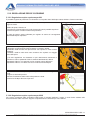
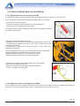
5.4. SCARICO SERBATOIO SEME
Per lo scarico semi dalla tramoggia seguire le seguenti istruzioni:
• Agendo sulla leva 1 abbassare il supporto tubi discesa grano 2.
• Sganciare le vasche raccogli semi 3 e posizionarle sotto le bocchette uscita semi.
• Spostare la leva del dosatore 4 in posizione di scarico per scaricare la tramoggia.
• Terminata l’operazione riposizionare le vaschette la bussoliera e la leva del dosatore in posizione di lavoro
5.5. REGOLAZIONE ORGANI DI DISTRIBUZIONE
Per ottenere un corretto investimento di semina è necessario registrare gli organi di distribuzione che sono:
1. Leva regolazione dei tastatori.
2. Rullo dosatore seme.
3. Lamine di chiusura bocchette.
5.5.1. Regolazione tastatori
La leva di regolazione dei tastatori agisce su una scala graduata.
In base al tipo di seme utilizzato per la semina, posizionare i tastatori
secondo le indicazioni riportate nella tabella di regolazione.
I tastatori correttamente posizionati assicurano una distribuzione fluida e
costante dei semi.
Per ottenere una distribuzione ottimale del seme verificare
periodicamente la posizione dei tastatori.
ISTRUZIONI PER L’USO - 16
Copyright ©2009 della Alpego srl ® -Tutti i diritti sono riservati. È espressamente vietata la ristampa o l’uso non autorizzato per iscritto da parte di Alpego spa
MANUALE SEMINATRICE MECCANICA M2 - M2S
Old Cod.Q00A00138
New Cod. MANT2010/00435 R.0
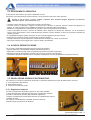
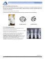
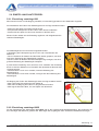
5.5.2. Regolazione rulli dosatori
Prima di iniziare la semina è necessario scegliere il tipo del rullo distributore in base alle dimensioni del seme
utilizzato.
La macchina è predisposta per la distribuzione dei semi normali e grandi. Nel caso di semi minuti, è necessario
utilizzare la corona destra del rullo distributore che è a denti piccoli e liberare dal trascinamento la corona sinistra a
denti grandi.
Per far questo è necessario spingere verso l’esterno della corona il fermo di trascinamento (1).
N.B: Fare attenzione al tipo di rullo da usare per la semina (vedi tabelle di semina)
RULLO GRANDE
RULLO PICCOLO
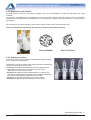
5.5.3. Regolazione lamine
Le lamine di chiusura bocchette di uscita del seme dalla tramoggia,
hanno 4 posizioni di regolazione.
Posizionare le lamine secondo le indicazioni riportate nella tabella di
semina in base al tipo di seme usato.
• Posizione 1: lamina tutta abbassata chiude completamente la
bocchetta di uscita del seme escludendo pertanto il rullo
distributore a cui non arrivano i semi.
• Posizione 2: alzando la lamina dalla posizione 1 si ottiene una
posizione di media apertura, indicata come da tabella allegata per
semi medi in quanto apre parzialmente la bocchetta.
• Posizione 3: apertura indicata per semi medi e grandi.
• Posizione 4: massima apertura indicata per semi grandi.
ISTRUZIONI PER L’USO - 17
Copyright ©2009 della Alpego srl ® -Tutti i diritti sono riservati. È espressamente vietata la ristampa o l’uso non autorizzato per iscritto da parte di Alpego spa
MANUALE SEMINATRICE MECCANICA M2 - M2S
Old Cod.Q00A00138
New Cod. MANT2010/00435 R.0
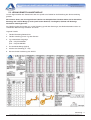
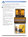
5.6. LETTURA TABELLA DI SEMINA
In base alle caratteristiche della seminatrice viene fornita una specifica tabella di regolazione per la distribuzione
della semina.
Si ricorda che le tabelle fornite hanno valore indicativo, poiché per uno stesso tipo di seme, la quantità
distribuita può subire delle variazioni secondo il peso specifico, l’umidità, la qualità ed il tipo del terreno.
Le tabelle indicano la posizione per impostare il cambio in relazione al tipo di seme, all’interfila di semina e alla
quantità di semi da distribuire.
Leggenda tabella:
1. Tabella regolazione seminatrice
2. Tabella di distribuzione in base al tipo di seme
3. Tipo di rinvio utilizzato
(Z18 – Z12) STANDARD
(Z12 – Z19) INVERSO
4. Quantità da distribuire (Kg/ha)
5. Posizione del cambio (0 – 100)
6. Schema per eseguire il TEST
ISTRUZIONI PER L’USO - 18
Copyright ©2009 della Alpego srl ® -Tutti i diritti sono riservati. È espressamente vietata la ristampa o l’uso non autorizzato per iscritto da parte di Alpego spa
MANUALE SEMINATRICE MECCANICA M2 - M2S
Old Cod.Q00A00138
New Cod. MANT2010/00435 R.0
5.7. PROVA DI SEMINA
Per una semina precisa è consigliabile effettuare una prova si semina a macchina ferma per il controllo della
quantità che di vuole seminare.
Durante la prova di semina, prestare la massima attenzione ai punti ove presentino parti in
movimento: albero agitatore, rulli dosatori, ecc.
Dopo aver configurato la macchina in base al tipo di semina che si desidera fare, procedere come segue:
•
Agendo sulla leva 1 abbassare il supporto tubi
discesa grano 2
•
Sganciare le vasche raccogli semi 3
posizionarle sotto le bocchette uscita semi
•
Riempire la tramoggia.
•
Inserire la manovella 5 nell’albero del rinvio e
girare in senso orario.
•
Prima di iniziare la prova, girare alcune volte la
manovella per caricare i distributori, quindi
scaricare le vasche raccogli seme.
•
Effettuare con la manovella, il numero di giri
ruota riportato in tabella in base al tipo di
macchina.
•
ATTENZIONE
i
giri
corrispondono ai giri ruota.
•
Pesare la quantità di seme raccolto nelle
vaschette è moltiplicarlo per 100, il valore
ottenuto sarà la quantità in Kg/Ha.
•
Se la nostra pesata dovesse darci un valore
superiore o inferiore a quella desiderata,
andremmo a diminuire o aumentare il valore da
impostare sul cambio.
manovella
e
non
ISTRUZIONI PER L’USO - 19
Copyright ©2009 della Alpego srl ® -Tutti i diritti sono riservati. È espressamente vietata la ristampa o l’uso non autorizzato per iscritto da parte di Alpego spa
MANUALE SEMINATRICE MECCANICA M2 - M2S
Old Cod.Q00A00138
New Cod. MANT2010/00435 R.0
5.8. ESCLUSIONE DI SEMINA MEZZA MACCHINA
Per eseguire lavori di fi nitura, la macchina è stata dotata di un sistema di esclusione ai distributori che permette di
escludere dalla semina, la parte sinistra della macchina.
• Per escludere la parte sinistra della macchina, portare la boccola 1 dalla posizione A alla posizione B, viceversa se
si vuole attivare tutta la macchina per la semina, portale la boccola 1 dalla posizione B alla posizione A.
5.9. REGOLAZIONE DISTANZA INTERFILA
Per modificare la distanza dell’interfila di semina togliere o
aggiungere gli assolcatori, seguendo le seguenti operazioni:
• Svitare i dadi 2 e togliere il cavallotto 1
• Sganciare la molla 3 dal telaio
• Ottenuto il numero degli assolcatori desiderato, portarli tutti
alla stessa distanza interfilare voluta.
• Controllare che siano aperte solo le lamine dei distributori
interessati agli assolcatori attivi, tutte le altre devono essere
posizionate in posizione 1
ISTRUZIONI PER L’USO - 20
Copyright ©2009 della Alpego srl ® -Tutti i diritti sono riservati. È espressamente vietata la ristampa o l’uso non autorizzato per iscritto da parte di Alpego spa
MANUALE SEMINATRICE MECCANICA M2 - M2S
Old Cod.Q00A00138
New Cod. MANT2010/00435 R.0
5.10. REGOLAZIONE DELLA PROFONDITÀ DI SEMINA
5.10.1. Regolazione profondità M2
In funzione delle condizioni del terreno e delle proprie abitudini si può regolare la profondità di semina.
Si consiglia di regolare con una pressione maggiore gli assolcatori che lavorano nelle tracce delle
ruote della seminatrice e del trattore.
Su tutte le seminatrici sono presenti delle manovelle attraverso le quali è possibile modificare contemporaneamente
la pressione degli assolcatori di un intero settore di semina.
Si può inoltre regolare la pressione, di ogni singolo assolcatore.
Regolazione contemporanea di tutti gli assolcatori.
• Girare la manovella 1 in senso antiorario per aumentare la pressione degli assolcatori sul terreno di conseguenza
una caduta del seme più profonda.
• Girare la manovella 1 in senso orario per diminuire la pressione degli assolcatori.
5.10.2. Regolazione profondità su M2S
La seminatrice a spaglio M2S una volta combinata sull’erpice non necessita d’alcuna regolazione, è importante
però:
• Regolare l’erpice rotante in posizione di lavoro in maniera da verificare la corretta profondità di semina.
• Regolare la barra affinamento posteriore montata sopra cui sono fissate le rastrelliere dei tubi di semina.
Questo dispositivo oltre ad assolvere le normali funzioni già descritte nel libretto uso e manutenzione dell’erpice
permette di regolare tramite la manovella B la profondità del letto di semina;
Regolare l’altezza dei bracci di sollevamento del trattore in modo tale che nella posizione di trasporto, la seminatrice
non tocchi il suolo.
ISTRUZIONI PER L’USO - 21
Copyright ©2009 della Alpego srl ® -Tutti i diritti sono riservati. È espressamente vietata la ristampa o l’uso non autorizzato per iscritto da parte di Alpego spa
MANUALE SEMINATRICE MECCANICA M2 - M2S
Old Cod.Q00A00138
New Cod. MANT2010/00435 R.0
5.11. REGOLAZIONE ASSOLCATORI
5.11.1. Regolazione assolcatore a zappetta (standard)
Per regolare la pressione di ogni singolo assolcatore a zappetta seguire le seguenti istruzioni.
• Allentare il bullone 1.
• Posizionare la slitta nella posizione voluta per aumentare o diminuire la profondità di semina.
• Stringere o se necessario posizionare la vite nell’altro foro
5.11.2. Regolazione assolcatore a disco (optional)
Eseguire le seguenti operazioni per l’assolcatore a dischi.
• Allentare il bullone 2
• Alzare la slitta 3 per aumentare la profondità di semina, abbassare la slitta per diminuire la profondità di semina.
• Chiudere il bullone 2
ISTRUZIONI PER L’USO - 22
Copyright ©2009 della Alpego srl ® -Tutti i diritti sono riservati. È espressamente vietata la ristampa o l’uso non autorizzato per iscritto da parte di Alpego spa
MANUALE SEMINATRICE MECCANICA M2 - M2S
Old Cod.Q00A00138
New Cod. MANT2010/00435 R.0
5.12. REGOLAZIONE ERPICE COPRISEME
5.12.1. Regolazione erpice copriseme per M2
È possibile regolare la pressione e l’inclinazione con la quale i denti dell’erpice stesso incidono il terreno seminato.
La pressione di lavoro delle molle erpice copriseme, può essere variata nel
seguente modo:
• Sfilare la spina 1 dal tubo 2.
• Comprimere / Decomprimere le molle 3 poste sul braccio parallelo superiore.
• Inserire la spina 1 nel tubo 2 nella nuova posizione.
Le molle 3 possono essere utilizzate per regolare lo scarico di conseguenza
l’altezza dell’erpice copriseme.
Ci sono due modi per regolare l’erpice:
1) Regolare la tensione della molla avvitando o svitando i dadi 4.
• Avvitando i dadi la molla avrà più tensione che equivale un minor scarico
dell’erpice.
• Svitando i dadi la molla avrà meno tensione che equivale un maggior
carico dell’erpice.
2) Se tale regolazione non bastasse si può ulteriormente aumentare o
diminuire lo scarico spostando il blocco tensione 5 allentando i dadi 6.
• Spostando il blocco 7 in avanti si avrà un maggior carico dell’erpice.
• Spostando il blocco 7 in dietro si avrà un minor scarico dell’erpice
L’inclinazione delle molle erpice copriseme può essere variata nel seguente
modo.
• Togliere la vite 8 dal perno 9.
• Ruotare l’inclinazione delle molle nella posizione voluta.
• Inserire la vite 8 per bloccare il perno 9
5.12.2. Regolazione erpice copriseme per M2S
Per l’erpice copriseme della seminatrice M2S esiste il manuale dedicato il quale vi verrà fornito assieme alla
documentazione della macchina. Seguire scrupolosamente le istruzioni per il suo utilizzo.
ISTRUZIONI PER L’USO - 23
Copyright ©2009 della Alpego srl ® -Tutti i diritti sono riservati. È espressamente vietata la ristampa o l’uso non autorizzato per iscritto da parte di Alpego spa
MANUALE SEMINATRICE MECCANICA M2 - M2S
Old Cod.Q00A00138
New Cod. MANT2010/00435 R.0
6. MANUTENZIONE
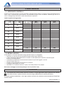
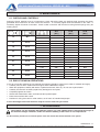
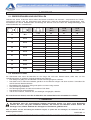
6.1. VERIFICHE E CONTROLLI
Durante le prime 8 ore di lavoro e’ bene controllare il serraggio di tutti i bulloni, in quanto lo sforzo generato durante il
lavoro crea un assestamento della struttura, eventualmente stringere come da tabella, verificare ogni 50 ore di
lavoro il fissaggio degli assolcatori e delle molle dell’erpice copriseme.
Tabella coppia di serraggio (Nm)
13
M8
17
M 10
19
M 12
22
M 14
24
M 16
27
M 18
30
M 20
32
M 22
36
M 24
8.8
10.9
12.9
[ Nm ]
[ Nm ]
[ Nm ]
1.25
25
37
44
1.00
27
40
47
1.50
50
73
86
1.25
53
78
91
1.75
86
127
148
1.25
95
139
163
2.00
137
201
235
1.50
150
220
257
2.00
214
314
369
1.50
229
336
393
2.50
306
435
509
1.50
345
491
575
2.50
432
615
719
1.50
482
687
804
2.50
502
843
987
1.50
654
932
1090
3.00
744
1080
1240
2.00
814
1160
1360
6.2. MESSA A RIPOSO
A fine stagione, o nel caso si preveda un lungo periodo di riposo, è consigliabile:
• Scaricare con cura tutte le sementi dalla tramoggia e dagli organi distributori.
• Lavare l’attrezzatura abbondantemente con acqua, in modo particolare il serbatoio, quindi asciugarla.
Evitare l’uso dell’idropulitrice.
• Controllare accuratamente ed eventualmente sostituire le parti danneggiate o usurate.
• Serrare a fondo tutte le viti .
• Passare con del lubrificante tutte le parti non verniciate.
• Proteggere l’attrezzatura con un telo.
• Sistemarla in un ambiente asciutto e in piano, fuori dalla portata dei non addetti.
Sarà vostro vantaggio nel trovarla pronta per l’uso la prossima volta.
7. ACCESSORI
La macchina può essere fornita di diversi accessori; ad ogni applicazione tenere presente che variano i
pesi della macchina e quindi verificare che non venga compromessa la stabilità del trattore.
Per quanto riguarda l’installazione e l’uso degli eventuali accessori fare riferimento alla documentazione allegata agli
accessori stessi.
MANUTENZIONE - 24
Copyright ©2009 della Alpego srl ® -Tutti i diritti sono riservati. È espressamente vietata la ristampa o l’uso non autorizzato per iscritto da parte di Alpego spa
MANUALE SEMINATRICE MECCANICA M2 - M2S
Old Cod.Q00A00138
New Cod. MANT2010/00435 R.0
NOTE:
ACCESSORI - 25
Copyright ©2009 della Alpego srl ® -Tutti i diritti sono riservati. È espressamente vietata la ristampa o l’uso non autorizzato per iscritto da parte di Alpego spa
USATE SEMPRE RICAMBI ORIGINALI
EMPLOYEZ TOUJOURS LES PIECES DE RECHANGE ORIGINALES
IMMER DIE ORIGINAL-ERSATZTEILE VERWENDEN
ALWAYS USE ORIGINAL SPARE PARTS
USAR SIEMPRE REPUESTOS ORIGINALES
ALPEGO s.r.l Via Torri di Confine, 6 36053 GAMBELLARA – VICENZA – ITALY
Tel 0444/646100 – fax 0444/646199
E-mail: info @ alpego.com Internet www.alpego.com
Copyright ©2009 della Alpego srl ® -Tutti i diritti sono riservati. È espressamente vietata la ristampa o l’uso non autorizzato per iscritto da parte di Alpego srl
6(('(50(5&85<
0
06
Codice
Q00A00138
Da matr:
30318
*%
USE AND MAINTENANCE MANUAL
A matr:
INSTRUCTION TRANSLATED FROM THE ORIGINAL
USE AND MAINTENANCE MANUAL SEEDER M2 - M2S
Old Cod.Q00A00138
New Cod. MANT2010/00440 R.0
ALPEGO s.p.a.
MACCHINE ED ATTREZZATURE PER LA
LAVORAZIONE DEL TERRENO , SINGOLE
E COMBINATE
DISSODATORI, COLTIVATORI
ERPICI ROTANTI , FRESATRICI –
TRIVELLE
36053 GAMBELLARA VICENZA ITALIA
VIA TORRI DI CONFINE , 6
TEL. 0444/646100 - FAX 0444/646199
E-mail: info @ alpego.com
Internet: www.alpego.com
CAP. SOCIALE L. 199.000.000
PART. IVA 02009840246
C.C.I.A.A. 199795
REG. SOC. TRIB. VI N° 22374
N. MECC. VI011754
I
GB
D
F
E
Dichiarazione CE
di conformità’
ai sensi della direttiva
CE 2006/42
EC Certificate
of conformity
conforming to
EEC Directions
2006/42
EG Konformitatserklarung
entsprechend der
EG-Richtlinie
2006/42 EWG
Wir
Déclaration de
conformité pour la
CE
conforme à la directive
de la 2006/42 CE
Nous
Declaraciòn CE
de conformidad.
Conforme a la
directiva CE 2006/42
la empresa / el
productor
La ditta
sottoscritta
We
ALPEGO s.p.a.
VIA TORRI DI CONFINE N°6
36053 GAMBELLARA -(VI)-ITALIA
dichiara sotto
la propria
responsabilità’
che la macchina
modello :
Codice / Code:
declare in sole
responsability,
that the
product
model :
to which this
applies, conforms
to the basic safety
and health
requirements of
EC Directions
2006/42
Per l’adeguamento For the adaptation of
delle
macchine it blots some have
sono state adottate been adopted the
norms:
le norme:
Gambellara:
UNI EN 708
UNI EN ISO 4254-1
UNI EN 14018
UNI EN 982
ISO 3757-2
ISO 11684
declara bajo su
propia
responsabilidad que
la màquina
modelo:
déclarons sous
notre seule
responsabilite’
que le produict
modéle :
MODELLO MACCHINA
SEMINATRICI «SEMIN_AS3__40032_IDRO_PLUS»
È’ Conforme ai
requisiti Essenziali
di Sicurezza e di
Tutela della Salute
di cui alla
Direttiva CE
2006/42
UNI EN 708
UNI EN ISO 4254-1
UNI EN 14018
UNI EN 982
ISO 3757-2
ISO 11684
erklaren in alleineger
Verantwortung,
da das
Produkt
Typ :
N° matricola / serial n°:
auf das sich diese
Erklarung bezeith,
den
einschlagigen
grundlegenden
Sicherheits und
Gesundheitsanforderungen
der EG-Richtlinie
2006/42 EWG
Für die Anpassung von ihr
befleckt
einiges
sind
angenommen worden den
Normen:
faisant l’objet de
la
déclaration
est
conforme
aux
prescriptions
fondamentales
en
matière de sècuritè et
de santè
stipulèes
dans la Directive de la
CE
2006/42
Pour l'adaptation d'elle
en éponge ont été
adoptés les normes :
està conforme a los
requisitos esenciales de
seguridad y de defeusa de
la salud de la directiva
CE 2006/42
Para la equparaciòn de
las màquinas nan sido
adoptado las normas
UNI EN 708
UNI EN ISO 4254-1
UNI EN 14018
UNI EN 982
ISO 3757-2
ISO 11684
UNI EN 708
UNI EN ISO 4254-1
UNI EN 14018
UNI EN 982
ISO 3757-2
ISO 11684
UNI EN 708
UNI EN ISO 4254-1
UNI EN 14018
UNI EN 982
ISO 3757-2
ISO 11684
La ditta
2
Copyright ©2009 Alpego spa ® - Al rights reserved. Any reprinting or inauthorized use without the written permission of Alpego s.p.a. is expressly prohibited
USE AND MAINTENANCE MANUAL SEEDER M2 - M2S
Old Cod.Q00A00138
New Cod. MANT2010/00440 R.0
Please read this owner’s manual carefully before using the
instrument. The Knowlwedge of its contents is essential for
the safe use of the machine and it must be Kept during the
entire life span of the implement
We thank you for choosing this product. You have purchased a high-quality instrument,
guaranteed by an experience of dozens of years.
Each instrument is carefully checked before it leaves our Company, so as to guarantee
that it is free of defects. However, should a defect in the material still occur, please
contact your Dealer immediately.
In order to constantly improve our products and to keep them at the highest quality levels
we are gladly at your disposal for any explanation or piece of information you may require.
PAY ATTENTION TO THIS TRIANGLE. IT WARNS YOU AGAINST DANGER
THE TERM MACHINE REPLACES THE COMMERCIAL BRAND NAME WHICH THE
PRESENT OWNER’S MANUAL REFERS TO
The illustrations in this Owner’s Manual have a purely indicative value. They may,
therefore, present some small differences which are, however, uninfluential as far
as the directions given in this Owner’s Manual are concerned.
N.B.: view of the machine.
ALPEGO normally considers the machine as being viewed from the
rear to identify better the particulars and to better assemble the parts that
must respect the position “right or left” as in description (e.g.: right or left
cardan joint, right or left tine, etc.)
3
Copyright ©2009 Alpego spa ® - Al rights reserved. Any reprinting or inauthorized use without the written permission of Alpego s.p.a. is expressly prohibited
Index
1. GENERAL INFORMATION ........................................................................................................................................ 1 1.1. PURPOSE OF THE MANUAL ............................................................................................................................. 1 1.2. DOCUMENTS SUPPLIED WITH THE MACHINE ............................................................................................... 1
1.3. GUARANTEE ....................................................................................................................................................... 1 1.4. MACHINE IDENTIFICATION ............................................................................................................................... 1 2. TECHNICAL SPECIFICATIONS ................................................................................................................................ 2 2.1. MACHINE DESCRIPTION ................................................................................................................................... 2 2.2. SEEDER COMPONENTS.................................................................................................................................... 2 2.3. TECHNICAL DATA .............................................................................................................................................. 3 2.3.1. Technical data table of M2 ............................................................................................................................. 3
2.3.2. Technical data table of M2S........................................................................................................................... 3
2.4. SOUND LEVEL .................................................................................................................................................... 3 3. SAFETY REGULATIONS .......................................................................................................................................... 4 3.1. TO USE IN SAFETY ............................................................................................................................................ 4 3.2. MAINTENANCE IN SAFETY ............................................................................................................................... 6 3.3. TRANSPORT ON PUBLIC ROADS ..................................................................................................................... 6 3.4. CLOTHING ........................................................................................................................................................... 6 3.5. ECOLOGY............................................................................................................................................................ 6 3.6. SAFETY SIGNS ................................................................................................................................................... 7 4. INSTALLATION ......................................................................................................................................................... 9 4.1. MOVEMENT AND TRANSPORT ........................................................................................................................ 9 4.2. LIFTING................................................................................................................................................................ 9 4.3. INSTALLATION THE SEEDER ......................................................................................................................... 10 4.3.1. Assembling the components ........................................................................................................................ 10 4.3.2. Applying to harrow ....................................................................................................................................... 12 4.4. CHECKING THE LIFTING ABILITY AND THE STABILITY OF THE TRACTOR .............................................. 13
5. USE ........................................................................................................................................................................... 15 5.1. MACHINE START-UP........................................................................................................................................ 15 5.2. SOWING ............................................................................................................................................................ 15 5.3. TANK SUPPLYING ............................................................................................................................................ 16 5.4. SEED TANK DRAIN ........................................................................................................................................... 16 5.5. ADJUSTMENT OF THE DISTRIBUTION ELEMENTS ...................................................................................... 16 5.5.1. Feeler adjustment ........................................................................................................................................ 16 5.5.2. Seed dispenser roller adjustment................................................................................................................. 17 5.5.3. Plate adjustment........................................................................................................................................... 17 5.6. READING ADJUSTMENT TABLE ..................................................................................................................... 18 5.7. TEST TO CHECK THE AMOUNT OF SEED TO BE DISTRIBUTED................................................................ 19 5.8. SOWING EXCLUSION FROM HALF THE MACHINE ...................................................................................... 20 5.9. ADJUSTMENT OF SPACING BETWEEN ROWS ............................................................................................ 20 5.10. SOWING DEPTH ADJUSTMENT .................................................................................................................... 21 5.10.1. Adjustment depth on M2 ............................................................................................................................ 21 5.10.2. Adjustment depth on M2S .......................................................................................................................... 21 5.11. ADJUSTING OF THE SINGLE COULTER ...................................................................................................... 22 5.11.1. Adjusting the hoe coulter (standard) .......................................................................................................... 22 5.11.2. Adjusting the disc coulter (optional) ........................................................................................................... 22 5.12. SEED COVERING REGULATION HARROW ................................................................................................. 23 5.12.1. Adjustment seed covering harrow for M2 .................................................................................................. 23 5.12.2. Adjustment seed covering harrow for M2S ................................................................................................ 23 Copyright ©2009 Alpego spa ® - Al rights reserved. Any reprinting or inauthorized use without the written permission of Alpego s.p.a. is expressly prohibited
USE AND MAINTENANCE MANUAL SEEDER M2 - M2S
Old Cod.Q00A00138
New Cod. MANT2010/00440 R.0
6. MAINTENANCE ....................................................................................................................................................... 24 6.1. CHECKS AND CONTROLS............................................................................................................................... 24 6.2. END OF SEASON OPERATIONS ..................................................................................................................... 24 7. ACCESSORIES ........................................................................................................................................................ 24 Copyright ©2009 Alpego spa ® - Al rights reserved. Any reprinting or inauthorized use without the written permission of Alpego s.p.a. is expressly prohibited
USE AND MAINTENANCE MANUAL SEEDER M2 - M2S
Old Cod.Q00A00138
New Cod. MANT2010/00440 R.0
1. GENERAL INFORMATION
1.1. PURPOSE OF THE MANUAL
This manual was created by the machine producer and is an integral part of the documentation that accompanies the
machine.
The manual defines the purpose for which the machine was produced, it establishes correct machine application and
limits of use.
The constant application of the indications given in this manual guarantees the safety of those who use the machine,
as well as working economy and longer machine duration.
This manual has been divided into sections. To make it easier to find a specific topic, consult the initial index.
The images that appear in this manual are given as an example. Even if substantially different from the machine you
possess, the safety and information are guaranteed.
1.2. DOCUMENTS SUPPLIED WITH THE MACHINE
The following documents should be supplied with the machine:
• User and maintenance manual
• Spare parts catalogue
• EC Conformity Declaration
The machine may be supplied complete with different options/fittings. For the assembly and the use of those check
the specific manuals supplied with the documents of the machine
COD.
Q00A00119
Q00A00132
D12339
DESCRIPTION
Owner’s Manual of the row-marking discs
Owner’s Manual of the following harrow
Owner’s Manual of the “Plus” Computer
1.3. GUARANTEE
When delivered, make sure that the machine and any accessories were not damaged during transport.
Any complaints should be presented in writing within 6 days from the date of delivery.
GUARANTEE FORFEITURE
The guarantee is rendered null and void immediately if:
•
•
•
•
there is a manoeuvring error
the instructions described in this manual are not followed
original spare parts are not used
any modification is made to the machine without having obtained authorisation from the manufacturer.
1.4. MACHINE IDENTIFICATION
On the left front section of the seed box there is a machine identification plate which carries the following information
1. Machine type
2. Serial number
3. Maximum weight of the machine with roller
4. Year of production
The indicated weight refers to the machine complete with standard
shoe coulters
GENERAL INFORMATION - 1
Copyright ©2009 by Alpego spa ® -All rights reserved. Any reprinting or unauthorized use without the written permission of Alpego spa is expressly prohibited.
USE AND MAINTENANCE MANUAL SEEDER M2 - M2S
Old Cod.Q00A00138
New Cod. MANT2010/00440 R.0
2. TECHNICAL SPECIFICATIONS
2.1. MACHINE DESCRIPTION
The machine is basically made up of a load bearing frame, to which are applied the seed hopper and the sowing
devices. The seeder is ideal for working in combination with a harrow transported by a tractor, equipped with lifting
group and a three point hitch
The seeder should only be used for agricultural work, and more specifically for sowing on soil.
It is ideal for sowing cereals: Wheat, barley rye, oats, rice
For fine seeds and fodder: Rape, clover, alfalfa, rye-grass
For big seeds:
Soya, peas
The seeds are distributed in the ground continuously and not one by one through an alveolar roller for each row,
because they are set into the soil by Suffolk coulters in the M2F model and by disc coulters in the M2D model and by
a set of drilling hoses mounted on the leveling bar of the power harrow in the M2S model. The quantities of seed
drilled are adjusted by a variable speed drive (gearbox) which is driven by the ground wheel, which in turn is made
to rotate by its adherence to the ground.
The coulters in the M2 models are independent of each other and allow for a wide fluctuation range in order for them
to adjust to the soil surface: in the M2S model, once the leveling bar has been properly adjusted, the drilling depth
remains constant. A single operator is able to perform all drilling operations from his tractor seat
2.2. SEEDER COMPONENTS
The main components are:
1. Seed tank
6. Coulter
7. Following harrow
2. Seed collecting trays
6A. Suffolk coulter
8. Gear box
3. Ground wheel
6B. Disc coulter
9. Tie-rod of upper link
4. Platform for filling the tank
6C. Broadcast drilling bar
10. Power harrow
5. Set of lights for circulation on
public roads
TECHNICAL SPECIFICATIONS - 2
Copyright ©2009 by Alpego spa ® -All rights reserved. Any reprinting or unauthorized use without the written permission of Alpego spa is expressly prohibited.
USE AND MAINTENANCE MANUAL SEEDER M2 - M2S
Old Cod.Q00A00138
New Cod. MANT2010/00440 R.0
2.3. TECHNICAL DATA
Hereafter the data related to the various models of seeder sowers are reported
2.3.1. Technical data table of M2
model
M2-300 F
M2-300 D
M2-350 F
M2-350 D
M2-400 F
M2-400 D
cm.
300
300
350
350
400
400
cm.
300
300
350
350
400
400
n°
24
24
28
28
32
32
cm.
12.5
12.5
12.5
12.5
12.5
12.5
Hopper
capacity
litres
Kg.
700
700
700
700
700
700
?
?
?
?
?
?
Hopper
capacity
litres
Kg.
700
700
700
?
?
?
2.3.2. Technical data table of M2S
model
M2S-300
M2S-350
M2S-400
cm.
300
350
400
cm.
300
350
400
n°
24
28
32
cm.
spaglio
spaglio
spaglio
2.4. SOUND LEVEL
If the tractor has the cab, the sound level depends on the type of insulation of the cab.
If the tractor has no cab or if the windows are open, the sound level of the working machine
measured at 200 mm. from the rear window exceeds 85 dBa. Therefore, we suggest to use
soundproofing headphones as prescribed by the laws of several Countries
TECHNICAL SPECIFICATIONS - 3
Copyright ©2009 by Alpego spa ® -All rights reserved. Any reprinting or unauthorized use without the written permission of Alpego spa is expressly prohibited.
USE AND MAINTENANCE MANUAL SEEDER M2 - M2S
Old Cod.Q00A00138
New Cod. MANT2010/00440 R.0
3. SAFETY REGULATIONS
3.1. TO USE IN SAFETY
•
Read the user and maintenance manuals carefully before starting, using and carrying out maintenance on the
equipment.
•
The producer cannot be held responsible for any injury caused to people or animals, and damage to things
because of the non observance of the safety regulations.
•
The machine cannot be used for purposes other than those expressly indicated in this manual
•
Avoid absolutely to touch in any way the parts in motion
•
The machine and eventually its accessories for the transport on public roads must be complete with the
necessary signs and adequate protections.
•
It is forbidden for people to drive the tractor if they do not have a suitable driving licence, if they do not have the
necessary experience, or if they are not in good health.
•
Carefully examine the adhesive labels on the machine and respect the indications they give. Safety stickers
should always be legible. They should be kept clean and they must be replaced when they cannot be read
properly (if required, replacements can be requested from your dealer)
•
While working do not allow people, animals or things to approach the working range of the sods and stones that
are being thrown out by the machine
•
It is absolutely forbidden to enter the area between the tractor and the machine to
reach the external commands of the hydraulic lifter.
•
You must always remain seated in the tractor driving seat. You can only leave your
driving seat when the tractor power takeoff has been disengaged and the
handbrake pulled up.
•
During working stops: switch off the motor, place the machine on the ground, disengage tractor power takeoff
and pull the tractor handbrake up.
•
Never work if the protections have been removed.
•
Never use the machine to transport people, animals or things
•
Do not work on ground or in places that compromise machine stability.
•
Familiarize with the area where you need to work. Never operate in an area in which there are obstacles like
stones, sticks or roots. They might damage the machine.
•
For the transport on public roads always use the danger-warning blinking lights
safety regulations - 4
Copyright ©2009 by Alpego spa ® -All rights reserved. Any reprinting or unauthorized use without the written permission of Alpego spa is expressly prohibited.
USE AND MAINTENANCE MANUAL SEEDER M2 - M2S
Old Cod.Q00A00138
New Cod. MANT2010/00440 R.0
•
When circulating on public roads, observe the rules in force in each country. It is very important to remember that
road holding, braking capacity and direction are influenced by the weight of the machine applied to the lifting
device of the tractor. Moreover, when turning bends consider the effect of the centrifugal force that shifts the
machine centre of gravity
•
Do not take turns while the machine is resting in the ground. Never
work in reverse Always lift the machine when changing direction or
reversing.
•
During transportation, or every time it becomes necessary to lift the machine, it is advisable to calibrate the lifting
device of the tractor so that the machine is not lifted from the ground by more than 35 cm approximately. Avoid
driving on public roads with the machine soiled with earth, grass or other materials which may cause dirtying of
the road or hindrances to street traffic. Do not lower the machine abruptly to the ground. Instead lower it slowly in
order to allow the tines to gradually penetrate into the soil. Unless this operation is performed in the way
described, the components of the machine would undergo very strong stresses which could compromise their
integrity.
•
During transportation on public roads with the machine raised, put the lever of the hydraulic lift of the tractor in
the blocked position
•
Use only the universal joints supplied by the manufacturer and provided with the safety devices against
overloads
•
Before inserting the power take off, check the pre-defined r.p.m. Do not confuse 540 r.p.m. with 1000 r.p.m.
•
The universal joint must always be mounted and taken off with the engine switched off.
•
La protezione dell’albero cardanico deve essere sempre efficiente, va controllata
periodicamente , e fissata con le catenelle per impedirne la rotazione.
•
Always disconnect the power takeoff when the universal joint forms an angle
exceeding 15°, see figure.
•
Before inserting the p.t.o make sure that there are no persons or animals within the action area and that the
r.p.m. you have chosen is the one allowed. Never exceed the max. r.p.m. allowed.
•
In order to avoid burnings do not touch the gear box after the machine has worked for a lengthy period of time..
•
Before changing the gears in the gearbox, disconnect the power takeoff, switch off the tractor engine, activate
the tractor parking brake and remove the ignition key. After you have performed the operation, replace the lid of
the gearbox.
safety regulations - 5
Copyright ©2009 by Alpego spa ® -All rights reserved. Any reprinting or unauthorized use without the written permission of Alpego spa is expressly prohibited.
USE AND MAINTENANCE MANUAL SEEDER M2 - M2S
Old Cod.Q00A00138
New Cod. MANT2010/00440 R.0
3.2. MAINTENANCE IN SAFETY
•
DO NOT allow unauthorised people to carry out maintenance operations or to tamper with the machine in any
way.
•
Maintenance and repairs should be carried out in a suitable and well equipped workshop.
•
Always use original accessories and spare parts as instructed by the manufacturer. If you fail to do this, the
guarantee will be rendered null and void, and you could risk operational irregularities that could prejudice the
safety of the machine.
•
When carrying out maintenance on the machine disconnect the hydraulic hoses from the tractor inlets.
•
When carrying out any kind of operation on the machine, disengage the tractor power takeoff, pull the handbrake
up, remove the ignition key and make sure that nobody gets into the tractor.
3.3. TRANSPORT ON PUBLIC ROADS
If necessary the machine can be transported on road coupled to the tractor; the operator must verify, confront and to
adapt the equipment for the full respect of the Highway Code of the country of it is used .
Pay attentions to:
1. for the coupling of the machine to the tractor it is necessary to follow the instructions brought back in the manual
present.
2. It is obliged to respect all the norms for the safeguard of his life and that one of the others, adopting all the
possible precautions.
3. It is necessary to preview all the protections for all the elements outside of the dimension width of the machine
4. respect of the limits of lateral overhang from the limits tractors.
5. When circulating on the road, the machine and any accessories must have suitable signals and protection
systems.
6. Always remember that roadholding, braking and changing direction could be influenced by the weight of the
machine applied to the tractor lifter.
7. When taking turns, take into consideration the action of the centrifugal force that moves the machine barycentre.
8. During transportation, or whenever it is necessary to lift the machine, the tractor lifting group should be regulated
in such a manner as to keep the machine at a maximum distance of approx. 35 cm from the ground.
3.4. CLOTHING
You should put on clothes protecting the body with no hanging parts that could get stuck in moving components.
Remove watches, rings, necklaces, etc. that could cause injury in dangerous situations. Pull up long hair into a
ponytail
The machine driver may have to wear suitable safety equipment (glasses,
gloves, mask, helmet, shoes, etc.).
3.5. ECOLOGY
Regulations in your country regarding the use and disposal of lubricating products, maintenance operations and
machine cleaning must be respected. Carefully observe the indications given on the packaging of the products
used. Respect current standards for scrapping the machine
safety regulations - 6
Copyright ©2009 by Alpego spa ® -All rights reserved. Any reprinting or unauthorized use without the written permission of Alpego spa is expressly prohibited.
USE AND MAINTENANCE MANUAL SEEDER M2 - M2S
Old Cod.Q00A00138
New Cod. MANT2010/00440 R.0
3.6. SAFETY SIGNS
A good number of labels on the machine point out the sources of danger. Observe them carefully and follow the
indications for a safe use of the machine. These stickers should be kept clean and legible; if damaged they should
be replaced
safety regulations - 7
Copyright ©2009 by Alpego spa ® -All rights reserved. Any reprinting or unauthorized use without the written permission of Alpego spa is expressly prohibited.
USE AND MAINTENANCE MANUAL SEEDER M2 - M2S
FIGURE
INDICATIONS
FIGURE
Old Cod.Q00A00138
New Cod. MANT2010/00440 R.0
INDICATIONS
ATTENTION
The regulation and maintenance
operations must be carried out
after reading the use and
maintenance handbook, with the
machine stopped and the key
removed.
ATTENTION
NOISY AREA this sign marks
the zones of the machine where
the noise level can be such to
provoke
damages
to
the
auditory apparatus. In presence
of this, it
is mandatory to use protective
devices for the auditory
apparatus of the type prescribed
by the enforced norms.
ATTENTION
DANGER of fl uids under
pressure. Read the handbook
before intervening and consult a
doctor in case of wounds
ATTENTION
Maximum limit of rpm.
DANGER of contact with cardan
shaft in motion.
ATTENTION
DANGER of crushing. Do not stop
between the traction engine or
and the machine.
ATTENTION
DANGER of toxic substances.
ATTENTION
DANGER of crushing. Do not stop
between the traction engine or
and the machine.
ATTENTION
DANGER
of
suspended parts.
ATTENTION
DANGER of chopping of the
hands.
LIFTING POINT
ATTENTION
Prohibited to
transported.
ATTENTION
mount
and
falling
be
Use the required
Protection Devises.
ATTENTION
Kinematic
mechanisms
in
movement. If you approach the
machine
without
the
due
precautions there is a high risk of
accident.
GREASING POINTS
of
Individual
ATTENTION
DANGER
of
catching
and
dragging. Do not put your hands
near the driving shaft in motion.
safety regulations - 8
Copyright ©2009 by Alpego spa ® -All rights reserved. Any reprinting or unauthorized use without the written permission of Alpego spa is expressly prohibited.
USE AND MAINTENANCE MANUAL SEEDER M2 - M2S
Old Cod.Q00A00138
New Cod. MANT2010/00440 R.0
4. INSTALLATION
4.1. MOVEMENT AND TRANSPORT
Pay the maximum attention to safety during the loading and unloading operations that have to be carried out by
qualifi ed
staff (people assigned to slinging operations and to the carriage, etc.).
In case of lifting the machine, it is obligatory to use of the appropriate lifting points indicated by the pictograms.
A motor vehicle with suitable power and dimensions must be used for the transport of the machine, opportunely
predisposed.
Once loaded, the machine must be fi xed using anchorage ropes.
4.2. LIFTING
The machine should be lifted and transported with
the right means, suitable for its weight, and by
personnel trained in this kind of work. Hook the
machine in the two points indicated in the figure and
proceed. A chain that is suitable for the machine capacity
can be hooked to the rear (footplate) but a homologated belt
is recommended for the front to stop the hopper from being
damaged. Hook the two chains or belts (at a height that
does not ruin the machine surfaces) to a single chain for
lifting. The machine should not be raised by more than 200
mm from the ground while carrying out these operations
INSTALLATION - 9
Copyright ©2009 by Alpego spa ® -All rights reserved. Any reprinting or unauthorized use without the written permission of Alpego spa is expressly prohibited.
USE AND MAINTENANCE MANUAL SEEDER M2 - M2S
Old Cod.Q00A00138
New Cod. MANT2010/00440 R.0
4.3. INSTALLATION THE SEEDER
Adjustments and regulations should be
made while the tractor is off, the ignition
key is out and the seeder is firmly
supported on its own support legs
In order to mount the seed drill M2 on a power harrow
the following elements are required:
• The seed drill connecting arms 1
• The brackets 2 for the quick-hitch of the roller
• The tie-rod of the upper link 3
4.3.1. Assembling the components
For the assembly of the elements perform the following steps:
1. Attach the arms A to the seed-drill frame by using the bolts B and the brackets C
Mercury M2
Mercury M2S
INSTALLATION - 10
Copyright ©2009 by Alpego spa ® -All rights reserved. Any reprinting or unauthorized use without the written permission of Alpego spa is expressly prohibited.
USE AND MAINTENANCE MANUAL SEEDER M2 - M2S
Old Cod.Q00A00138
New Cod. MANT2010/00440 R.0
The standard holes for attaching the arm A are the central ones, but, depending on how the seed drill is fitted, it can
be mounted closer to or farther from the power harrow by using different holes
Should the mounting position be
modified from the standard one,
correct the tilt angle through the tie
rod of the upper link , so that the seed
drill can work in a horizontal position.
For a correct position check the
indicator which is to be found on the
side of the hopper.
2. Fasten the D brackets of the quick-hitch of the roller by means of
the E U-bolts
The fastening width of the A arms on the frame of the seed drill
will have to be the same as the width of the D brackets. It varies
depending on the position of the plates connecting the roller to
the power harrow.
INSTALLATION - 11
Copyright ©2009 by Alpego spa ® -All rights reserved. Any reprinting or unauthorized use without the written permission of Alpego spa is expressly prohibited.
USE AND MAINTENANCE MANUAL SEEDER M2 - M2S
Old Cod.Q00A00138
New Cod. MANT2010/00440 R.0
4.3.2. Applying to harrow
Applying the machine to a tractor is a very delicate phase, so be very careful when following the
instructions. Work on a horizontal surface with the seeder placed steadily on its support legs
Once the power harrow has been hitched to the tractor, perform the following steps:
•
With the tractor in reverse gear drive close to the seed drill and, using the lifting device, hook the arms A on the
brackets B.
•
Insert the pins C and secure them with the safety bolts
•
Connect the tie rod of the upper link and lift the machine in order to remove the supporting stands
•
Lower the lifting device, thereby setting the thus combined implements into their working position
•
Connect the telescopic hoses D with the drilling hoses which are
to be found on the leveling bar E (only for the M2S seed dill
model).
•
Make sure that all drilling elements, such as the ground wheel
and the following harrow, are free to fluctuate. Make sure that
the combined implements are in the correct position,
perpendicular to the ground: if they are not, adjust by acting on
the tie rod of the upper link.
INSTALLATION - 12
Copyright ©2009 by Alpego spa ® -All rights reserved. Any reprinting or unauthorized use without the written permission of Alpego spa is expressly prohibited.
USE AND MAINTENANCE MANUAL SEEDER M2 - M2S
Old Cod.Q00A00138
New Cod. MANT2010/00440 R.0
4.4. CHECKING THE LIFTING ABILITY AND THE STABILITY OF THE TRACTOR
When an implement is hitched to a tractor, it becomes an integral part thereof as far as road circulation is
concerned. This implement may alter the stability of the tractor and cause some driving and working difficulty
The hitching of an implement to a tractor involves a different distribution of the weights on its axles. Depending on
the composition of the machine, it is, therefore, advisable to add ballast to the front end of the tractor so as to
adequately distribute the weight on the axles
were:
A
= Distance of the front axle from the front ballast (m)
B
= Tractor wheel base (m)
2
C
= Distance of the rear axle from the lower links of the implement 3-point hitch (m)
2
Gv
= Weight of ballast (kg)
3
Te
= Empty weight of the tractor
Tv
= Load on the tractor’s front axle when empty
2
2
Th
= Load on the tractor’s rear axle when empty
Lb tot = Distance from the lower hitch to the center of gravity of the complete implement combination (m)
2
3
Lb1
= Distance from the lower links of hitch to the center of gravity of the first combined machine (m)
1
Lb2
= Distance from the lower links of hitch to the center of gravity of the second combined machine (m)
1
Lb3
= Distance from the lower links of hitch to the center of gravity of the third combined machine (m)
1
Lb4
= Distance from the lower links of hitch to the center of gravity of the fourth combined machine (m)
1
Mb1
= Overall mass of the first implement (kg)
4
Mb2
= Overall mass of the second implement (kg)
4
Mb3
= Overall mass of the third implement (kg)
4
Mb4
= Overall mass of the fourth implement (kg)
4
Mb tot = Overall mass of the total combined machine (kg)
2
1 = Must be measured.
2 = Check the tractor operation and maintenance manual.
3 = Must be calculated.
4 = Consult the operation and maintenance manual of the required implement.
INSTALLATION - 13
Copyright ©2009 by Alpego spa ® -All rights reserved. Any reprinting or unauthorized use without the written permission of Alpego spa is expressly prohibited.
USE AND MAINTENANCE MANUAL SEEDER M2 - M2S
Old Cod.Q00A00138
New Cod. MANT2010/00440 R.0
Use the following formula to calculate how much ballast is needed:
Gv min. = (Mb tot x (C + Lb tot)) – (Tv x B) + (0,2 x Te x B)
----------------------------------------------------------------A+B
The distance from the center of gravity of the combined machine to the lower links of the hitch of the tractor is
calculated with the following formula
Lb tot = (Lb1 x Mb1) + (Lb2 x Mb2) + (Lb3 x Mb3) + (Lb4 x Mb4) + (Lb….x Mb….)
-----------------------------------------------------------------------------------------------------Mb1+Mb2+Mb3+Mb4+Mb….
The overall mass of the entire combined machine is calculated with the following formula
Mb tot = Mb1+Mb2+Mb3+Mb4+Mb…..
At any rate, at least 20% of the combined
weight of tractor+hitched implement must rest
on the front carriage of the tractor for it to be
suited to move safely. Always keep in mind
that, besides the correct combination of tractor
and implement, adding ballast to the front of
the tractor, within the limits and following the
directions given by the manufacturer of the
tractor, can improve its stability. Moreover,
when the tractor is stationary, the hitched
implement must be lowered to the ground.
This will prevent possible accidental falls,
while improving the tractor stability.
Tractor wheelbase
B
=………… m
Distance of the front axle from
the front ballast
A
=………… m
Tractor weight
Te
=……………Kg
Ballast weight
Gv
=……………Kg
Load on the tractor’s axle
when empty
Tv
=……...
Kg
Implement weight:
Mb tot =……...
Kg
Tot center of gravity length:
Lb tot =…………….m
INSTALLATION - 14
Copyright ©2009 by Alpego spa ® -All rights reserved. Any reprinting or unauthorized use without the written permission of Alpego spa is expressly prohibited.
USE AND MAINTENANCE MANUAL SEEDER M2 - M2S
Old Cod.Q00A00138
New Cod. MANT2010/00440 R.0
5. USE
5.1. MACHINE START-UP
funzionanti. Before using the machine, it is necessary to familiarize with the controls and their operation capacity.
Before starting the work make sure that there are no people or animals in the action area.
Before starting the job, verify perfectly that ALL the protections of the machine are integral and working.
5.2. SOWING
Once the sowing machine is correctly towed and connected with a tractor, you can prepare it for sowing.
Preliminary operations
• Check that all transmission drive lines are connected correctly.
• Load the seed tanks, ensuring that no foreign bodies enter the tanks.
• Free the row tracer arms
Configuration
To obtain correct seed density per hectare (Kg/Ha), the distribution organs must be properly adjusted, namely:
• Feeler adjustment.
• Seed dispenser roller adjustment.
• Plate adjustment.
• Amount of seed distribution adjustment
Setting-up
• Perform a TEST to check the amount of seed to be distributed.
• Turn the drive wheel to send part of the seed from the hopper to the dispensers and from these to the
individual coulters.
• Make sure all the coulters dispensed seeds.
Checks while sowing
Once all the previously mentioned operations have been carried out, the sowing machine is ready for working.
However we recommend you to run a few meters in both directions to make sure that you are sowing as required.
In particular:
• The cutters’ supply tubes are positioned correctly and there should be no throttling or folds along all the tubes;
• Sowing depth corresponds to the desired one;
• The coverage of the seed is suffi cient;
• The driving wheel turns in a constant and uniform way;
• There are no blockings in the hopper, caused especially by glume seeds.
• Avoid turning and driving in the reverse, when the machine is under ground. ALWAYS LIFT the machine to change
direction and reverse gear.
• Ensure that sowing speed is aligned with the type of ground being worked in order to avoid any machine breakage
or damage.
• It is forbidden for persons to stand or work in proximity of containers with chemical substances, or open containers
when the seeder is operating, or about to do so.
use - 15
Copyright ©2009 by Alpego spa ® -All rights reserved. Any reprinting or unauthorized use without the written permission of Alpego spa is expressly prohibited.
USE AND MAINTENANCE MANUAL SEEDER M2 - M2S
Old Cod.Q00A00138
New Cod. MANT2010/00440 R.0
5.3. TANK SUPPLYING
The supply of the tanks can be made by hand. Remember that the lifting of weights exceeding 30 kg requires the
intervention of more operators
During the loading and unloading phases of the tanks, the operator must use adequate Individual Protection
Devices (gloves, coveralls, masks, etc)
• The tanks must be filled once the land to be sowed is reached.
• All the tank’s loading and unloading operations are carried out on the land to be sowed, with the sowing machine
stopped on the land, the chassis open, parking brake set in action, engine stopped and ignition key removed from
the control panel.
• Lower completely the lifter and activate the tractor’s parking brake.
• It is advisable to carry out these operations in a flat area without obstacles.
• Ensure that nobody can approach the chemical substances.
• Pay attention so that no foreign objects enter the tank during the filling operations.
• To control that stoppers of every tank are closed, therefore to proceed to the filling of the tanks.
5.4. SEED TANK DRAIN
To drain the seeds from the hopper, follow the instructions below:
• Act on the lever 1 to lower the grain descent tube support 2
• Release the seed collecting trays 3 and position them below the seed outlets
• Shift the lever of the dispenser 4 to drain the hopper
• When the operation has been completed, re-position the bush housing and the dispenser lever in the work position.
5.5. ADJUSTMENT OF THE DISTRIBUTION ELEMENTS
In order to set the optimum drilling quantity it is necessary to adjust the distribution elements, which are:
1. The feeler adjusting lever
2. The seed measuring roller
3. The outlet shutting plates
5.5.1. Feeler adjustment
The adjustment lever of the feelers acts on a graduated scale.
Depending on the type of seed used, position the feelers according to the
indications carried on the adjustment table.
Correctly positioned feelers ensure fl uid and constant seed distribution.
To obtain the best seed distribution, check the feeler position regularly.
use - 16
Copyright ©2009 by Alpego spa ® -All rights reserved. Any reprinting or unauthorized use without the written permission of Alpego spa is expressly prohibited.
USE AND MAINTENANCE MANUAL SEEDER M2 - M2S
Old Cod.Q00A00138
New Cod. MANT2010/00440 R.0
5.5.2. Seed dispenser roller adjustment
Before starting to sow, choose the type of roller you will use taking into consideration the size of the seeds to be
sown.
The machine can be used to sow both normal and big seeds. If you are sowing tiny seeds, use the right-hand
distribution wheel because it has small teeth, and stop the left-hand wheel (big teeth) from dragging
To do this push the drive stop towards the outside of the crown (1).
N.B: Be careful when selecting the type of wheel to be used for sowing (see sowing table)
BIG WHEEL
SMALL WHEEL
5.5.3. Plate adjustment
The outlet closing plates of the seeds leaving the hopper can be
adjusted in 4 positions.
Position the plates according to the indications carried on the seed
table depending on the type of seed used.
• Position 1: plate lowered all the way closing the seed outlet
completely, thus excluding the distribution roller which receives no
seeds.
• Position 2: lifting the plate from position 1 obtains a medium
opened position, indicated as on the attached table for medium
seeds since the outlet opens partially.
• Position 3: opening recommended for medium and large seeds.
• Position 4: maximum opening recommended for large seeds.
use - 17
Copyright ©2009 by Alpego spa ® -All rights reserved. Any reprinting or unauthorized use without the written permission of Alpego spa is expressly prohibited.
USE AND MAINTENANCE MANUAL SEEDER M2 - M2S
Old Cod.Q00A00138
New Cod. MANT2010/00440 R.0
5.6. READING ADJUSTMENT TABLE
Depending on the features of the planter, a specifi c seed distribution adjustment table is provided.
Remember that the tables supplied have an indicative value since for the same type of seed, the amount
to be distributed can change depending on specific weight, moisture, quality and type of soil.
Le tabelle indicano la posizione per impostare il cambio in relazione al tipo di seme, all’interfila di semina e alla
quantità di semi da distribuire.
The tables indicate the position to set the gear depending on the type of seed, seed spacing and the amount of seed
to be distributed.
Table key:
1. Planter adjustment table
2. Distribution table depending on type of seed
3. Type of transmission used
(Z18 – Z12) STANDARD
(Z12 – Z19) INVERTED
4. Amount to distribute (Kg/ha)
5. Position of gear (0 – 100)
6. Layout for performing TEST
use - 18
Copyright ©2009 by Alpego spa ® -All rights reserved. Any reprinting or unauthorized use without the written permission of Alpego spa is expressly prohibited.
USE AND MAINTENANCE MANUAL SEEDER M2 - M2S
Old Cod.Q00A00138
New Cod. MANT2010/00440 R.0
5.7. TEST TO CHECK THE AMOUNT OF SEED TO BE DISTRIBUTED
For precise sowing, it is recommended to perform a seed test with the machine stationary to check the amount of
seed to be sown.
During this test, be very careful to the points with moving parts: agitator shaft, seed dispenser rollers,
etc.
After having set the machine according to the type of seed, proceed as follows:
•
Act on the lever 1 to lower the grain descent
tube support 2
•
Release the seed collecting trays 3 and position
them below the seed outlets
•
Fill the hopper.
•
Insert the handwheel 5 in the transmission shaft
and turn it clockwise.
•
Before beginning the test, turn the handwheel a
few times to load the distributors. Then unload
the seed collection trays.
•
Turn the handwheel as many times as shown
on the table depending on the type of machine.
•
Weigh the seeds collected in the tray and
multiply by 100. The result will be the amount of
Kg/Ha.
•
SIf the weight is greater or less than the one
desired, we must decrease or increase the
value to set on the gearshift.
use - 19
Copyright ©2009 by Alpego spa ® -All rights reserved. Any reprinting or unauthorized use without the written permission of Alpego spa is expressly prohibited.
USE AND MAINTENANCE MANUAL SEEDER M2 - M2S
Old Cod.Q00A00138
New Cod. MANT2010/00440 R.0
5.8. SOWING EXCLUSION FROM HALF THE MACHINE
In order to perform fi nishing jobs, the machine is equipped with a system for excluding distributors on the left part of
the machine from sowing.
• To exclude the left part of the machine, bring the bush 10 from position A to position B. Vice verse to activate the
entire machine for sowing, bring bush 10 from position B to position A.
5.9. ADJUSTMENT OF SPACING BETWEEN ROWS
To change the seed spacing between rows, add or remove
coulters, operating as follows:
• Unscrew the nuts 2 and remove the u-bolt 1
• Release the spring 3 from the frame
• When you have reached the desired number of coulters, bring
them all to the same spacing distance.
• Make sure all the plates of the active coulter distributors are
open all the others must be placed at position 1
use - 20
Copyright ©2009 by Alpego spa ® -All rights reserved. Any reprinting or unauthorized use without the written permission of Alpego spa is expressly prohibited.
USE AND MAINTENANCE MANUAL SEEDER M2 - M2S
Old Cod.Q00A00138
New Cod. MANT2010/00440 R.0
5.10. SOWING DEPTH ADJUSTMENT
5.10.1. Adjustment depth on M2
Sowing depth can be adjusted depending on the conditions of the soil and one own habits.
It is recommended to adjust the coulters working behind the wheels of the planter and tractor at a
higher pressure.
All the planters have handwheels to modify the pressure of the coulters of an entire sowing sector simultaneously.
The pressure of each individual coulter can be adjusted as well.
Simultaneous adjustment of all coulters
• Turn the handwheel 1 anti-clockwise to increase the pressure of the coulters on the soil for deeper sowing.
• Turn the handwheel 1 clockwise to decrease pressure of the coulters.
5.10.2. Adjustment depth on M2S
The M2S wheelbarrow seeder does not need to be regulated when it is coupled to the harrow, but the following
points are very important:
• Regulate the rotating harrow when it is in the working position to check the correct sowing depth.
• Regulate the rear clod smasher, which is positioned above the harrow, and to which the sowing pipe racks
are fixed. As well as carrying out the normal functions already described in the harrow user and
maintenance manual, this device can be used to regulate the sowing bed depth using handle B.
Regulate the height of the tractor lifting arms so that the seeder does not touch the ground while being transported.
use - 21
Copyright ©2009 by Alpego spa ® -All rights reserved. Any reprinting or unauthorized use without the written permission of Alpego spa is expressly prohibited.
USE AND MAINTENANCE MANUAL SEEDER M2 - M2S
Old Cod.Q00A00138
New Cod. MANT2010/00440 R.0
5.11. ADJUSTING OF THE SINGLE COULTER
5.11.1. Adjusting the hoe coulter (standard)
Follow the instructions below on how to adjust the pressure of each hoe coulter
• Undo bolt 1
• Move the slide to the required position, to increase or decrease the seed depth.
• Tighten, or if necessary put the screw in the other hole.
5.11.2. Adjusting the disc coulter (optional)
Follow these instructions on how to adjust the disc lister.
• Undo bolt 2
• Lift the slide 3 to increase the seed depth or lower it to decrease the seed depth.
• Tighten bolt 2.
use - 22
Copyright ©2009 by Alpego spa ® -All rights reserved. Any reprinting or unauthorized use without the written permission of Alpego spa is expressly prohibited.
USE AND MAINTENANCE MANUAL SEEDER M2 - M2S
Old Cod.Q00A00138
New Cod. MANT2010/00440 R.0
5.12. SEED COVERING REGULATION HARROW
5.12.1. Adjustment seed covering harrow for M2
It is possible to adjust the pressure and inclination with which the teeth of the harrow cut the sown soil.
The work pressure of the seed-covering harrow springs can vary as follows:
• Pull the pin 1 out from the tube 2.
• Compress / depress the springs 3 placed on the top parallel arm.
• Insert the pin 1 in the tube 2 in the new position.
The springs 3 can be used to regulate the drain and consequently the height of
the seed-covering harrow.
There are two ways to regulate the harrow:
1) Regulate the tension of the spring by loosening and tightening the nuts 4.
• By tightening the spring there will be more tension, which means less
discharge of the harrow.
• By loosening the spring there will be less tension, which means more
discharge of the harrow.
2) If this regulation is not enough, the discharge can be further increased or
decreased, shifting the tension block 5 loosening the nuts 6.
• Shifting the block 7 forward, there is greater harrow load.
• Shifting the block 7 backward, there is less harrow load.
Inclination of the seed-covering harrow springs can vary as follows.
• Remove the screw 8 from the pin 9.
• Rotate the inclination of the springs to the desired position.
• Insert the screw 8 to block the pin 9.
5.12.2. Adjustment seed covering harrow for M2S
For the following harrow of the M2S seed drill there is a special Owner’s Manual, which is supplied together with the
relevant documents accompanying the machine. Carefully follow the instructions for its use.
use - 23
Copyright ©2009 by Alpego spa ® -All rights reserved. Any reprinting or unauthorized use without the written permission of Alpego spa is expressly prohibited.
USE AND MAINTENANCE MANUAL SEEDER M2 - M2S
Old Cod.Q00A00138
New Cod. MANT2010/00440 R.0
6. MAINTENANCE
6.1. CHECKS AND CONTROLS
During the first 8 working hours it is important to check that all the bolts are perfectly tight, because the power
generated while machine is at work moves the structure. If necessary tighten bolts as indicated in the chart. If
necessary, tighten as shown in the table. Check coulter connection and the seed covering harrow springs every 50
working hours
13
M8
17
M 10
19
M 12
22
M 14
24
M 16
27
M 18
30
M 20
32
M 22
36
M 24
8.8
10.9
12.9
[ Nm ]
[ Nm ]
[ Nm ]
1.25
25
37
44
1.00
27
40
47
1.50
50
73
86
1.25
53
78
91
1.75
86
127
148
1.25
95
139
163
2.00
137
201
235
1.50
150
220
257
2.00
214
314
369
1.50
229
336
393
2.50
306
435
509
1.50
345
491
575
2.50
432
615
719
1.50
482
687
804
2.50
502
843
987
1.50
654
932
1090
3.00
744
1080
1240
2.00
814
1160
1360
6.2. END OF SEASON OPERATIONS
If you do not use the machine for long periods, the following should be carried out in order to maintain its integrity:
• Carefully remove all the seeds from the hopper and the distribution organs.
• Wash the equipment carefully with water, in particular the tank, then dry. Do not use a hydrocleaner.
• Carefully check and if necessary replace any damaged or worn parts.
• Completely tighten all screws.
• Grease the transmission chain, and lubricate all unpainted parts.
• Protect the machine with a cloth.
• Position it in a dry place and on a flat surface, out of reach of unauthorised people.
It is an advantage to have the machine ready for use the next time you need it.
7. ACCESSORIES
The machine can be equipped with different options: for each addition keep in mind that the weight of
the machine changes. Therefore, make sure that the stability of the tractor is not compromised.
For the assembly and the use of eventual options check the relevant documents attached to the options
maintenance - 24
Copyright ©2009 by Alpego spa ® -All rights reserved. Any reprinting or unauthorized use without the written permission of Alpego spa is expressly prohibited.
USE AND MAINTENANCE MANUAL SEEDER M2 - M2S
Old Cod.Q00A00138
New Cod. MANT2010/00440 R.0
NOTE:
accessories - 25
Copyright ©2009 by Alpego spa ® -All rights reserved. Any reprinting or unauthorized use without the written permission of Alpego spa is expressly prohibited.
USE AND MAINTENANCE MANUAL SEEDER M2 - M2S
Old Cod.Q00A00138
New Cod. MANT2010/00440 R.0
NOTE:
accessories - 26
Copyright ©2009 by Alpego spa ® -All rights reserved. Any reprinting or unauthorized use without the written permission of Alpego spa is expressly prohibited.
USATE SEMPRE RICAMBI ORIGINALI
EMPLOYEZ TOUJOURS LES PIECES DE RECHANGE ORIGINALES
IMMER DIE ORIGINAL-ERSATZTEILE VERWENDEN
ALWAYS USE ORIGINAL SPARE PARTS
USAR SIEMPRE REPUESTOS ORIGINALES
ALPEGO s.p.a
Sede Amministrativa: Via Torri di Confine, 6 36053 GAMBELLARA (VICENZA) – ITALY
Sede Legale: Via Giovanni e Giuseppe Cenzato, 9 36045 LONIGO (VICENZA) – ITALY
Tel: 0444/646100 – fax: 0444/646199
E-mail: info @ alpego.com Internet: www.alpego.com
Copyright ©2009 Alpego spa ® - Al rights reserved. Any reprinting or inauthorized use without the written permission of Alpego s.p.a. is expressly prohibited
6b0$6&+,1(0(5&85<
0
06
Codice
Q00A00138
Da matr:
30318
'
BETRIEBS – UND
WARTUNGSANLEITUNG
A matr:
HINWEISUNGEN VOM ORIGINAL ÜBERSETZT
BETRIEBS-UND WARTUNGSANLEITUNG SÄMASCHINE M2
- M2S
ALPEGO s.p.a.
Old Cod.Q00A00138
New Cod. MANT2010/00439 R.0
MACCHINE ED ATTREZZATURE PER LA
LAVORAZIONE DEL TERRENO , SINGOLE
E COMBINATE
DISSODATORI, COLTIVATORI
ERPICI ROTANTI , FRESATRICI –
TRIVELLE
36053 GAMBELLARA VICENZA ITALIA
VIA TORRI DI CONFINE , 6
TEL. 0444/646100 - FAX 0444/646199
E-mail: info @ alpego.com
Internet: www.alpego.com
CAP. SOCIALE L. 199.000.000
PART. IVA 02009840246
C.C.I.A.A. 199795
REG. SOC. TRIB. VI N° 22374
N. MECC. VI011754
I
GB
D
F
E
Dichiarazione CE
di conformità’
ai sensi della direttiva
CE 2006/42
EC Certificate
of conformity
conforming to
EEC Directions
2006/42
EG Konformitatserklarung
entsprechend der
EG-Richtlinie
2006/42 EWG
Wir
Déclaration de
conformité pour la
CE
conforme à la directive
de la 2006/42 CE
Nous
Declaraciòn CE
de conformidad.
Conforme a la
directiva CE 2006/42
la empresa / el
productor
La ditta
sottoscritta
We
ALPEGO s.p.a.
VIA TORRI DI CONFINE N°6
36053 GAMBELLARA -(VI)-ITALIA
dichiara sotto
la propria
responsabilità’
che la macchina
modello :
Codice / Code:
declare in sole
responsability,
that the
product
model :
to which this
applies, conforms
to the basic safety
and health
requirements of
EC Directions
2006/42
Per l’adeguamento For the adaptation of
delle
macchine it blots some have
sono state adottate been adopted the
norms:
le norme:
Gambellara:
UNI EN 708
UNI EN ISO 4254-1
UNI EN 14018
UNI EN 982
ISO 3757-2
ISO 11684
declara bajo su
propia
responsabilidad que
la màquina
modelo:
déclarons sous
notre seule
responsabilite’
que le produict
modéle :
MODELLO MACCHINA
SEMINATRICI «SEMIN_AS3__40032_IDRO_PLUS»
È’ Conforme ai
requisiti Essenziali
di Sicurezza e di
Tutela della Salute
di cui alla
Direttiva CE
2006/42
UNI EN 708
UNI EN ISO 4254-1
UNI EN 14018
UNI EN 982
ISO 3757-2
ISO 11684
erklaren in alleineger
Verantwortung,
da das
Produkt
Typ :
N° matricola / serial n°:
auf das sich diese
Erklarung bezeith,
den
einschlagigen
grundlegenden
Sicherheits und
Gesundheitsanforderungen
der EG-Richtlinie
2006/42 EWG
Für die Anpassung von ihr
befleckt
einiges
sind
angenommen worden den
Normen:
faisant l’objet de
la
déclaration
est
conforme
aux
prescriptions
fondamentales
en
matière de sècuritè et
de santè
stipulèes
dans la Directive de la
CE
2006/42
Pour l'adaptation d'elle
en éponge ont été
adoptés les normes :
està conforme a los
requisitos esenciales de
seguridad y de defeusa de
la salud de la directiva
CE 2006/42
Para la equparaciòn de
las màquinas nan sido
adoptado las normas
UNI EN 708
UNI EN ISO 4254-1
UNI EN 14018
UNI EN 982
ISO 3757-2
ISO 11684
UNI EN 708
UNI EN ISO 4254-1
UNI EN 14018
UNI EN 982
ISO 3757-2
ISO 11684
UNI EN 708
UNI EN ISO 4254-1
UNI EN 14018
UNI EN 982
ISO 3757-2
ISO 11684
La ditta
2
Copyright ©2009 der Alpego spa ® - Alle Rechte vorbehalten. Nachdruck, Vervielfältigung und Verbreitung, auch auszugsweise, ist ohne schriftliche Genehmigung der Alpego s.p.a
BETRIEBS-UND WARTUNGSANLEITUNG SÄMASCHINE M2
- M2S
Old Cod.Q00A00138
New Cod. MANT2010/00439 R.0
Vor Inbetriebnahme der Maschine sollte dieses Handbuch
aufmerksam durchgelesen werden. Seine Kenntnis ist
unentbehrlich für einen sicheren Gebrauch. Das Handbuch
ist für die gesamte Betriebszeit der Maschine
aufzubewahren.
Wir danken Ihnen für die getroffene Wahl. Sie haben ein Qualitätsprodukt erworben, das
eine jahrzehntelange Erfahrung aufweist.
Vor dem Verlassen der Fabrik wird jede Maschine sorgfältigst inspiziert, um sie vor dem
Auftreten von Mängeln zu schützen.
Sollte dennoch ein Materialmangel auftreten, benachrichtigen Sie bitte sofort Ihren
Vertragshändler.
In der Absicht, das Produkt stets zu verbessern und es auf höchstem Niveau zu halten,
stehen wir Ihnen für Erklärungen oder Auskünfte jederzeit zur Verfügung.
ACHTEN SIE AUF DAS DREIECK! ES SIGNALISIERT GEFAHR
DIE BEZEICHNUNG ‘MASCHINE’ ERSETZT DIE HANDELSBEZEICHNUNG, AUF DIE SICH
DAS VORLIEGENDE HANDBUCH BEZIEHT
ALLE IN DIESEM HANDBUCH ENTHALTENEN ANGABEN UND DATEN WERDEN
AUSKUNFTSWEISE ERTEILT UND VERPFLICHTEN DEN HERSTELLER IN
KEINSTER WEISE. ER KANN SIE AUCH OHNE VORANKÜNDIGUNG ÄNDERN.
N.B. Normalerweise betrachtet die Firma ALPEGO die Maschine von
hinten mit Blick in Fahrtrichtung, damit die speziellen und richtigen
Montagepositionen der Teile, die mit „rechts oder links“ beschriftet sind,
beachtet werden können. (Bsp. Kardan recht oder links, Hacke rechts
oder links)
3
Copyright ©2009 der Alpego spa ® - Alle Rechte vorbehalten. Nachdruck, Vervielfältigung und Verbreitung, auch auszugsweise, ist ohne schriftliche Genehmigung der Alpego s.p.a
Verzeichnis
1. ALLGEMEINE INFORMATIONEN ............................................................................................................................. 1 1.1. ZIEL DES HANDBUCHES ................................................................................................................................... 1 1.2. BEIGELEGTE DOKUMENTATION ...................................................................................................................... 1 1.3. GARANTIE ........................................................................................................................................................... 1 1.4. IDENTIFIKATION DER MASCHINE .................................................................................................................... 1 2. TECHNISCHE EIGENSCHAFTEN............................................................................................................................. 2 2.1. BESCHREIBUNG DER MASCHINE .................................................................................................................... 2 2.2. KOMPONENTEN DER SÄMASCHINE ............................................................................................................... 2 2.3. TECHNISCHE DATEN......................................................................................................................................... 3 2.3.1. Tabelle technischer daten M2 ........................................................................................................................ 3
2.3.2. Tabelle technischer daten M2S...................................................................................................................... 3
2.4. SCHALLPEGEL ................................................................................................................................................... 3 3. SICHERHEITSNORMEN............................................................................................................................................ 4 3.1. SICHERER GEBRAUCH ..................................................................................................................................... 4 3.2. SICHERE WARTUNG.......................................................................................................................................... 5 3.3. STRASSENVERKEHRSTEILNAHME ................................................................................................................. 5 3.4. ARBEITSKLEIDUNG ........................................................................................................................................... 5 3.5. ÖKOLOGIE .......................................................................................................................................................... 5 3.6. SICHERHEITSYMBOLE ...................................................................................................................................... 6 4. INSTALLATION ......................................................................................................................................................... 8 4.1. TRANSPORT UND HANDLING .......................................................................................................................... 8 4.2. AUFHEBUNG ....................................................................................................................................................... 8 4.3. INSTALLATION AUF DIE SÄMASCHINE ........................................................................................................... 9 4.3.1. Montage der komponenten ............................................................................................................................ 9
4.3.2. Aufbau auf die egge ..................................................................................................................................... 11 4.4. ÜBERPRÜFUNG DES AUFWERFENS VON ÄHIGKEIT UND VON STABILITÄT DES TRAKTOR MIT
KREISELEGGE ......................................................................................................................................................... 12 5. BENUTZUNG ........................................................................................................................................................... 14 5.1. STARTEN DER MASCHINE .............................................................................................................................. 14 5.2. AUSSAAT........................................................................................................................................................... 14 5.3. FÜLLEN DER TANKS ........................................................................................................................................ 15 5.1. ENTLADEN SAMENBEHÄLTER ....................................................................................................................... 15 5.2. EINSTELLUNG DER VERTEILUNGS-BESTANDETEILE ................................................................................ 15 5.2.1. Einstellung Taster ........................................................................................................................................ 15 5.2.2. Einstellung der Dosierrollen ......................................................................................................................... 16 5.2.3. Einstellung lamellen ..................................................................................................................................... 16 5.3. LESUNG EINSTELLUNGSTABELLE ................................................................................................................ 17 5.4. PRÜFUNGSTEST ZU VERTEILENDE MENGE................................................................................................ 18 5.5. AUSSCHLUSS HALBSAAT MASCHINE ........................................................................................................... 19 5.6. EINSTELLUNG REIHENABSTAND .................................................................................................................. 19 5.7. EINSTELLUNG DER SAATTIEFE ..................................................................................................................... 20 5.7.1. Einstellung der saattiefe M2 ......................................................................................................................... 20 5.7.2. Einstellung der saattiefe M2S ...................................................................................................................... 20 5.8. EINZELEINSTELLUNG DER FURCHENZIEHER ............................................................................................. 21 5.8.1. Einstellung der hackschar (standard) .......................................................................................................... 21 5.8.2. Einstellung der Scheiben-Säschar (optional) ............................................................................................... 21
5.9. EINSTELLUNG SAATSTRIEGEL ...................................................................................................................... 22 5.9.1. Einstellung saatstriegel M2 .......................................................................................................................... 22 5.9.2. Einstellung saatstriegel M2S ........................................................................................................................ 22 Copyright ©2009 der Alpego spa ® - Alle Rechte vorbehalten. Nachdruck, Vervielfältigung und Verbreitung, auch auszugsweise, ist ohne schriftliche Genehmigung der Alpego s.p.a
BETRIEBS-UND WARTUNGSANLEITUNG SÄMASCHINE M2
- M2S
Old Cod.Q00A00138
New Cod. MANT2010/00439 R.0
6. WARTUNG ............................................................................................................................................................... 23 6.1. ÜBERPRÜFUNGEN UND KONTROLLEN ........................................................................................................ 23 6.2. RUHESTELLUNG .............................................................................................................................................. 23 7. ZUBEHOR ................................................................................................................................................................ 23 Copyright ©2009 der Alpego spa ® - Alle Rechte vorbehalten. Nachdruck, Vervielfältigung und Verbreitung, auch auszugsweise, ist ohne schriftliche Genehmigung der Alpego s.p.a
BETRIEBS-UND WARTUNGSANLEITUNG SÄMASCHINE M2
- M2S
Old Cod.Q00A00138
New Cod. MANT2010/00439 R.0
1. ALLGEMEINE INFORMATIONEN
1.1. ZIEL DES HANDBUCHES
Dieses Handbuch wurde vom Maschinenhersteller verfasst und ist Teil der beigelegten Dokumentation.
Das Handbuch definiert das Ziel bzw. den Einsatz der Maschine und es erklärt ihre korrekte Verwendung und Handhabung sowie
die Grenzen ihres Gebrauchs.
Die konstante Durchführung der in diesem Handbuch enthaltenen Anweisungen garantiert die Sicherheit der Personen, die die
Maschine benutzen, ihre Betriebswirtschaftlichkeit und eine lange Funktionsdauer.
Das vorliegende Handbuch wurde in verschiedene Paragraphen unterteilt. Um die Suche nach Schlagwörter zu erleichtern,
schlagen Sie bitte im Verzeichnis am Anfang nach.
Die in diesem Handbuch enthaltene Bilder sind Beispiele. Sollten sich die Bilder unmerklich von der Maschine in Ihrem Besitz
unterscheiden, so werden Sicherheit und Richtigkeit der Auskünfte auf jeden Fall garantiert.
1.2. BEIGELEGTE DOKUMENTATION
Die Maschine ist folgende Dokumentation beigelegt:
•
•
•
Handbuch für Betrieb und Wartung
Ersatzteilkatalog
EG-Konformitätserklärung
Die Maschine kann mit verschiedenen Ausstattungen ausgerüstet werden. Um diese anzubauen und zu verwenden, wenden Sie
sich bitte den entsprechenden Betriebsanleitungen, die zusammen mit den Unterlagen der Maschine geliefert werden
COD.
Q00A00119
Q00A00132
D12339
BESCHREIBUNG
Betriebsanleitung bez. auf die Spuranreißer
Betriebsanleitung bez. auf den Saatstriegel
Betriebsanleitung bez. auf dem “Plus” computer
1.3. GARANTIE
Überprüfen Sie bitte sofort bei Lieferung, ob Maschine und/oder Zubehör während des Transports beschädigt worden sind.
VERFALL DER GARANTIE
Die Garantie verfällt sofort:
•
•
•
•
im Falle eines Bedienungsfehlers
im Falle der Nichtbeachtung der in diesem Handbuch enthaltenen Anweisungen
im Falle der Verwendung von nicht Original-Ersatzteilen
im Falle der Ausführung einer von dem Hersteller nicht genehmigten Änderung
1.4. IDENTIFIKATION DER MASCHINE
Auf der vorderen linken Seite des Behälters ist das Identifikationsschild der Maschine mit folgenden Daten angebracht:
1. Maschinenmodell
2. Matrikelnummer
3. Maximales Gewicht der Maschine mit Walze
4. Baujahr
Das angegebene Gewicht bezieht sich auf die Maschine mit Standardscharen
ALLGEMEINE INFORMATIONEN - 1
Copyright ©2009 der Alpego spa ® - Alle Rechte vorbehalten. Nachdruck, Vervielfältigung und Verbreitung, auch auszugsweise, ist ohne schriftliche Genehmigung der Alpego s.p.a
BETRIEBS-UND WARTUNGSANLEITUNG SÄMASCHINE M2
- M2S
Old Cod.Q00A00138
New Cod. MANT2010/00439 R.0
2. TECHNISCHE EIGENSCHAFTEN
2.1. BESCHREIBUNG DER MASCHINE
Die Maschine ist im wesentlichen auf einem Trägerrahmen konstruiert, auf dem der Samenbehälter und die
Aussaatvorrichtungen montiert sind. Die Sämaschine ist mit einer, auf eine landwirtschaftliche Zugmaschine
aufgebauten, Egge kombinierbar. Diese Zugmaschine muß mit einer Hebevorrichtungsgruppe und einem
universalen Drei-Punkt-Anschluß versehen sein.
Die Sämaschine ist ausschließlich zur landwirtschaftlichen Nutzung, zur Bodenaussaat bestimmt.
Sie ist geeignet für die Getreideaussaat von: Weizen, Gerste, Roggen, Hafer und Reis
Für die feine Samen und Futtermittel:
Raps, Klee, Saatluzerne, Lolch
Für grobe Samen:
Soja und Erbsen
The Samen werden kontinuierlich und nicht einzeln über ein Zellenrad für jede Reihe in den Boden verteilt, weil sie
durch Socken-Scharen im M2F Modell und Scheiben-Scharen im M2D Modell in den Boden eingesetzt werden. Im
M2S Modell werden die Samen durch einen Satz von Sä-Hosen, der auf der Nivellierschiene der Kreiselegge
montiert ist, ausgesät. Die verteilte Saatgutmenge wird über ein Variatorgetriebe eingestellt, das vom Spornrad
getrieben wird. Dieses wird durch seine Adhäsion am Boden in Bewegung gesetzt.
Die im Modell M2 vorhandenen Sä-Scharen sind unabhängig voneinander und weisen eine breite PendelnMöglichkeit auf, um sich der Boden-Oberfläche gut anpassen zu können. Nachdem die Nivellierschiene gut
eingestellt worden ist, wird das Sä-Verfahren im Modell M2S bei einer gleichmäßigen Tiefe erfolgen. Ein einziger
Bediener kann die verschiedenen Sä-Vorgänge von seinem Schlepper-Sitz ausführen.
2.2. KOMPONENTEN DER SÄMASCHINE
Die Hauptbestandteile sind:
1. Saatgut-Behälter
6. Schar
7. Saatstriegel
2. Saatgut-Sammelmulden
6A. Socken-Schar
8. Variatorgetriebe
3. Spornrad
6B. Scheiben-Schar
9. Zugstange des Oberlenkers
4. Belade-Trittbrett und –Steg
6C. Breitsaat-Schiene
10. Kreiselegge
5. Lichtsatzt für Transport auf
offentlichen Strassen
TECHNISCHE EIGENSCHAFTEN - 2
Copyright ©2009 der Alpego spa ® - Alle Rechte vorbehalten. Nachdruck, Vervielfältigung und Verbreitung, auch auszugsweise, ist ohne schriftliche Genehmigung der Alpego s.p.a
BETRIEBS-UND WARTUNGSANLEITUNG SÄMASCHINE M2
- M2S
Old Cod.Q00A00138
New Cod. MANT2010/00439 R.0
2.3. TECHNISCHE DATEN
In der Folge sind die technischen Daten der verschiedenen Modelle der Sämaschinen MagicSem angeführt.
2.3.1. Tabelle technischer daten M2
modell
M2-300 F
M2-300 D
M2-350 F
M2-350 D
M2-400 F
M2-400 D
cm.
cm.
n°
cm.
300
300
350
350
400
400
300
300
350
350
400
400
24
24
28
28
32
32
12.5
12.5
12.5
12.5
12.5
12.5
Fassungsver
mögen
Behälter
Liter
700
700
700
700
700
700
Kg.
?
?
?
?
?
?
2.3.2. Tabelle technischer daten M2S
modell
M2S-300
M2S-350
M2S-400
cm.
cm.
300
350
400
300
350
400
n°
24
28
32
cm.
spaglio
spaglio
spaglio
Fassungsver
mögen
Behälter
Liter
700
700
700
Kg.
?
?
?
2.4. SCHALLPEGEL
Ist der Traktor mit einer Kabine ausgerüstet, hängt der Schallpegel von der Art der
Kabinenisolierung ab. Hat der Traktor hingegen keine Kabine oder läuft bei geöffneten Fenstern,
so ist der bei Maschinen-betrieb erzeugte Geräuschpegel, 200 mm von der hinteren Scheibe
entfernt gemessen, höher als 85 dB(A). Demzufolge wird das Tragen von Gehörschutz, gemäß
den Arbeitsschutzbestimmungen einiger Länder, angeraten.
TECHNISCHE EIGENSCHAFTEN - 3
Copyright ©2009 der Alpego spa ® - Alle Rechte vorbehalten. Nachdruck, Vervielfältigung und Verbreitung, auch auszugsweise, ist ohne schriftliche Genehmigung der Alpego s.p.a
BETRIEBS-UND WARTUNGSANLEITUNG SÄMASCHINE M2
- M2S
Old Cod.Q00A00138
New Cod. MANT2010/00439 R.0
3. SICHERHEITSNORMEN
3.1. SICHERER GEBRAUCH
•
Bevor man die Maschine in Betrieb nimmt, sollte man die Betriebs- und die Wartungsanleitung sorgfältig gelesen
haben.
•
Der Hersteller lehnt jegliche Verantwortung in Bezug auf Schaden an Personen, Tieren oder Sachen, die durch
Nichtbeachtung der Sicherheitsmaßnahmen verursacht werden, ab.
•
Es ist nicht gestattet die Maschine für andere Zwecke einzusetzen, als der, der in diesem Handbuch
ausdrücklich angegeben ist.
•
Es ist grundsätzlich verboten, den Traktor von Personal führen zu lassen, das dafür keinen gültigen
Führerschein besitzt, unsachkundig oder krank ist.
•
Berücksichtigen Sie sorgfältig die Symbolaufkleber auf der Maschine und befolgen Sie diese Anweisungen. Die
Sicherheitsabziehbilder müssen immer gut sichtbar sein: sie müssen stets gesäubert und ersetzt werden, wenn
sie nicht mehr leserlich sind (ev. können sie beim Vertraghändler nachgefragt werden).
•
Während der Manöver ist es nicht erlaubt, daß sich Personen oder Tiere dem Betätigungsfeld der Maschine
nähern.
•
Es ist nicht erlaubt zwischen den Traktor und die Maschine zu treten, um die
externe Steuerung des hydraulischen Kräftehebers zu betätigen
•
Bleiben Sie stets auf dem Fahrersitz sitzen und steigen Sie nur ab, wenn die
Standbremse festgestellt ist.
•
Während der Arbeitspausen den Motor ausschalten, die Maschine auf dem Boden ablegen und die
Standbremse des Traktor anziehen. Arbeiten Sie nie ohne Schutz!
•
Vermeiden Sie es während der Arbeit mit der Maschine Kurven zu fahren und arbeiten Sie nie im
Rückwärtsgang. Heben Sie die Maschine bei jedem Fahrtrichtungswechsel und Wenden
•
Benutzen Sie die Maschine nie als Transportmittel für Personen,
Tiere oder Sachen.
•
Arbeiten Sie nicht auf unebenen Böden oder an Plätzen, an
denen die Stabilität der Maschine nicht mehr gewährleistet ist.
•
Lassen Sie die Maschine nie kraftvoll auf den Boden fallen,
sondern senken Sie sie langsam ab, so dass die Bleche graduell in den Boden geführt werden. Sollte das so
nicht geschehen riskiert man eine starke Belastung aller Komponenten, die ihre Zuverlässigkeit und
Unversehrtheit gefährden.
•
Die Sämaschine kann chemische Substanzen, die mit dem Samen vermischt sind, transportieren. Sorgen sie
dafür, daß sich keine andere Personen, Kinder und Haustiere der Maschine nähern.
•
Es darf sich niemand dem Saatgutbehälter nähern, noch versuchen ihn bei Betrieb oder während der
Inbetriebnahme zu öffnen.
•
Achten Sie darauf, daß beim Befüllen des Saatgutbehälters keine Fremdkörper hineingelangen (Fäden, Papier
etc.).
SICHERHEITSNORMEN - 4
Copyright ©2009 der Alpego spa ® - Alle Rechte vorbehalten. Nachdruck, Vervielfältigung und Verbreitung, auch auszugsweise, ist ohne schriftliche Genehmigung der Alpego s.p.a
BETRIEBS-UND WARTUNGSANLEITUNG SÄMASCHINE M2
- M2S
Old Cod.Q00A00138
New Cod. MANT2010/00439 R.0
3.2. SICHERE WARTUNG
•
•
•
•
•
Erlauben Sie niemandem, der nicht autorisiert ist, Arbeiten oder andere Eingriffe an der Maschine vorzunehmen.
Wartung und Reparationen dürfen nur von Werkstätten ausgeführt werden, die dafür ausgerüstet sind.
Verwenden Sie immer Originalzubehör und Originalersatzteile, um damit den nötigen Anforderungen des
Herstellers gerecht zu werden. Im gegenteiligen Falle verfällt nicht nur die Garantie, sondern es kann dadurch
auch zu Funktionsstörungen kommen, die die Sicherheit der Maschine beeinträchtigen.
Für die Wartung der Maschine die hydraulischen Leitungen vom Traktor lösen.
Für sämtliche Arbeiten an der Maschine den Motor des Traktors abstellen, die Standbremsen anziehen, den
Schlüssel herausziehen und darauf achten, daß keine unbefugten Personen auf den Traktor steigen.
3.3. STRASSENVERKEHRSTEILNAHME
Wenn das Gerät am Traktor angebaut über Straßen transportiert werden kann, muss der Fahrer sicherstellen, dass
die Ausrüstung voll der Straßenverkehrsordnung des Landes entspricht, in dem das Gerät benutzt wird. Sonst muss
die Ausrüstung an diese angepasst warden
Insbesondere ist folgendes zu berücksichtigen:
1. Zum Anbau des Geräts am Traktor sind die Anweisungen zu beachten, die in diesem Handbuch stehen.
2. Während des Transports ist das Gerät blockiert und vom Boden ausgehoben zu halten.
3. Verpflichtung zur Beachtung der Normen zur Wahrung der eigenen Unversehrtheit und der von Dritten, indem
alle möglichen Vorsichtsmaßnahen getroffen werden.
4. Überstehende Elemente sind mit Schutzvorrichtungen zu versehen.
5. Die gesamte Ausrüstung muss mit einer geeigneten Beleuchtungsanlage mit Anzeige- und Blinkelementen
versehen werden.
6. Wo vorgesehen, sind Schilder zur Anzeige des Platzbedarfs anzubringen.
7. Das Brems- und Lenkverhalten werden durch das Gewicht des Geräts beeinflusst, das am Kraftheber des
Traktors angebaut ist. Außerdem ist in Kurven zu berücksichtigen, dass die Fliehkraft den Schwerpunkt des
Geräts verschiebt.
8. Die Grenzwerte der Achslast berücksichtigen.
9. Die Grenzwerte des Überhangs und des seitlichen Überstands im Bezug zu den Grenzen des Traktors
einhalten.
3.4. ARBEITSKLEIDUNG
Tragen Sie bitte stets Schutzkleidung ohne hängende Teile, die sich in den bewegenden Komponenten der
Maschine verfangen könnten, nehmen Sie bitte Uhren, Ringe, Ketten etc. ab, da diese ebenfalls Unfallquellen
darstellen. Langes Haar muß zusammengebunden.
Der Benutzer hat, soweit es die geltenden Normen seines Landes
vorschreiben, die angebrachten Unfallverhütungsmaßnahmen zu beachten
wie z.Bsp. das Tragen von Schutzbrille, Handschuhen, Schutzhelm, festem
Schuhwerk usw
3.5. ÖKOLOGIE
Respektieren Sie die im eigenen Land geltenden Gesetze zum Gebrauch und Entsorgung der zum Schmieren, zur
Wartung und zur Maschinensäuberung verwendeten Produkte; befolgen Sie aufmerksam die Angaben auf den
Produktverpackungen.
Respektieren Sie auch die geltenden Vorschriften für die Maschinenverschrottung.
SICHERHEITSNORMEN - 5
Copyright ©2009 der Alpego spa ® - Alle Rechte vorbehalten. Nachdruck, Vervielfältigung und Verbreitung, auch auszugsweise, ist ohne schriftliche Genehmigung der Alpego s.p.a
BETRIEBS-UND WARTUNGSANLEITUNG SÄMASCHINE M2
- M2S
Old Cod.Q00A00138
New Cod. MANT2010/00439 R.0
3.6. SICHERHEITSYMBOLE
Die verschiedenen Aufkleber auf der Maschine dienen der Signalisierung einer Gefahrquelle. Beachten Sie sie
sorgfältig und folgen Sie deren Anweisungen für eine sichere Maschinenbenutzung. Sollten die Aufkleber beschädigt
sein, müssen sie unbedingt ersetzt werden
SICHERHEITSNORMEN - 6
Copyright ©2009 der Alpego spa ® - Alle Rechte vorbehalten. Nachdruck, Vervielfältigung und Verbreitung, auch auszugsweise, ist ohne schriftliche Genehmigung der Alpego s.p.a
BETRIEBS-UND WARTUNGSANLEITUNG SÄMASCHINE M2
- M2S
ETIKETT
BADEUTUNG
ETIKETT
Old Cod.Q00A00138
New Cod. MANT2010/00439 R.0
BADEUTUNG
ACHTUNG
Die Einstellungs- und
Wartungstätigkeiten dürfen erst
nach der Lektüre des Handbuchs
für Gebrauch und Wartung
vorgenomme
werden.
Die
Maschin
muss
dabei
ausgeschaltet
und
der
Zündschlüssel abgezogen sein.
ATTENZIONE
ZONA RUMOROSA questo
segnale contrassegna zone
della macchina dove il livello di
rumore può essere tale da
provocare danni all’apparato
uditivo.
In presenza di questo segnale è
obbligatorio l’uso di dispositivi di
protezione dell’apparato uditivo
del tipo prescritto dalle norme
vigenti
ACHTUNG
GEFAHR
von
unter
Druck
stehenden Flüssigkeiten. Vor
jedem Eingriff das Handbuch
lesen und im Fall einer Verletzung
einen Arzt konsultieren.
ACHTUNG
Grenzwert für U/m. GEFAHR
eines Kontakts mit der in
Bewegung
befi
ndlichen
Kardanwelle.
ACHTUNG
GEFAHR einer Quetschung. Kein
Stehen zwischen Traktor und
Maschine
ACHTUNG
GEFAHR giftiger Substanzen.
ACHTUNG
GEFAHR einer Quetschung. Kein
Stehen zwischen Traktor und
Maschine.
ACHTUNG
ACHTUNG
GEFAHR einer Verletzung der
Hände durch Scherstellen.
HEBEPUNKTE
ACHTUNG
Verbot eines Aufsteigens oder
Transportierens auf der Maschine.
ACHTUNG
ACHTUNG
in
Bewegung
befi
ndliche
Getriebeteile. Eine Annäherung
ohne
entsprechende
Vorsichtsmaßnahm en führt zu
einem hohen Unfallrisiko.
SCHMIERPUNK TE
GEFAHR eines Herabfallens
von schwebenden Teilen.
Verwenden
Sie
vorgeschriebene PSA.
die
ACHTUNG
GEFAHR eines Hängenbleibens
und Mitreißens. Die Hände nicht
in die Nähe der in Bewegung befi
ndlichen Antriebswelle bringen.
SICHERHEITSNORMEN - 7
Copyright ©2009 der Alpego spa ® - Alle Rechte vorbehalten. Nachdruck, Vervielfältigung und Verbreitung, auch auszugsweise, ist ohne schriftliche Genehmigung der Alpego s.p.a
BETRIEBS-UND WARTUNGSANLEITUNG SÄMASCHINE M2
- M2S
Old Cod.Q00A00138
New Cod. MANT2010/00439 R.0
4. INSTALLATION
4.1. TRANSPORT UND HANDLING
Sämtliche Tätigkeiten des Be- und Entladens müssen jedenfalls von Fachkräften (Stapelfahrer, Transportpersonal,
etc.)
ausgeführt werden und der Sicherheit ist dabei größte Bedeutung beizumessen.
Beim Heben der Maschine muss an den mit Piktogrammen angezeichneten Hebepunkten angesetzt werden.
Für den Transport der Maschine muss ein ausreichend dimensioniertes und starkes Fahrzeug verwendet werden,
das über die entsprechende Ausstattung verfügt.
Nach dem Aufl aden muss die Maschine mit Halteseilen gesichert werden.
4.2. AUFHEBUNG
Das Anheben und der Transport müssen mit dem
Gewicht der Maschine entsprechenden Geräten und
von dazu ausgebildetem Personal erfolgen. Klinken
Sie die Maschine - wie im Bild dargestellt - ein und führen den
Transport durch. Auf der Hinterseite (Leiter) kann eine
geeignete Kette eingehängt werden, während auf der
Vorderseite Bänder verwendet werden sollten, um den
Behälter nicht zu beschädigen. Hängen Sie für das Anheben
die zwei Ketten oder Bänder (so weit oben, daß die Oberfläche
nicht beschädigt wird) in eine einzige Kette ein.
Währenddessen darf die Maschine nicht höher als 200 m vom
Boden angehoben werden
INSTALLAtion - 8
Copyright ©2009 der Alpego spa ® - Alle Rechte vorbehalten. Nachdruck, Vervielfältigung und Verbreitung, auch auszugsweise, ist ohne schriftliche Genehmigung der Alpego s.p.a
BETRIEBS-UND WARTUNGSANLEITUNG SÄMASCHINE M2
- M2S
Old Cod.Q00A00138
New Cod. MANT2010/00439 R.0
4.3. INSTALLATION AUF DIE SÄMASCHINE
Alle Arbeiten dürfen nur bei abgestellten Motor und herausgezogenem Schlüssel durchgeführt
werden. Die Sämaschine muß dabei stabil mit ihren Stützbeinen auf dem Boden stehen.
Um die Sämaschine auf die Kreiselegge
anzubauen, sind folgende Bauteilen nötig:
• Die Arme 1 zur Ankuppelung der Sämaschine
• Die Bügel
Stützwalze
2 zur schnellen Ankuppelung der
• Die Zugstange 3 des Oberlenkers
4.3.1. Montage der komponenten
Per il montaggio dei componenti seguire i seguenti punti:
1. Fissare i bracci A al telaio della seminatrice utilizzando le viti B e le staffe C
Mercury M2
Mercury M2S
INSTALLAtion - 9
Copyright ©2009 der Alpego spa ® - Alle Rechte vorbehalten. Nachdruck, Vervielfältigung und Verbreitung, auch auszugsweise, ist ohne schriftliche Genehmigung der Alpego s.p.a
BETRIEBS-UND WARTUNGSANLEITUNG SÄMASCHINE M2
- M2S
Old Cod.Q00A00138
New Cod. MANT2010/00439 R.0
Die Standard-Bohrungen zur Befestigung der Arme A sind die Mittleren, aber, je nach Ausrüstung der Maschine,
darf die Sämaschine näherer oder weiter von der Kreiselegge angebaut werden, indem andere Bohrungen
verwendet werden.
Wenn die Befestigung-Lage geändert
wird, so muss die Neigung der
Maschine
durch
die
Zugstange
verbessert
werden,
damit
die
Sämaschine
waagerecht
arbeiten
kann.
Um die richtige Stellung zu erreichen,
helfen Sie sich mit dem Anzeiger, der
sich auf der Seite befindet.
2. Bügel D zur Ankuppelung der Stützwalze mittels der U-Bolzen
befestigen.
Die Breite zur Befestigung der Arme A auf dem Rahmen der
Sämaschine wird der Breite der Bügel D entsprechen müssen.
Sie ändert sich, je nach der Stellung der Platten zur Befestigung
der Stützwalze an der Kreiselegge
INSTALLAtion - 10
Copyright ©2009 der Alpego spa ® - Alle Rechte vorbehalten. Nachdruck, Vervielfältigung und Verbreitung, auch auszugsweise, ist ohne schriftliche Genehmigung der Alpego s.p.a
BETRIEBS-UND WARTUNGSANLEITUNG SÄMASCHINE M2
- M2S
Old Cod.Q00A00138
New Cod. MANT2010/00439 R.0
4.3.2. Aufbau auf die egge
Der Aufbau auf den Traktor ist eine sehr schwierige Phase. Dabei muß man darauf achten, daß der
gesamte Arbeitsvorgang den folgenden Anweisungen entspricht. Die Sämaschine muß stabil auf
ihren Stützbeinen stehen.
Nachdem die Kreiselegge am Schlepper angekuppelt worden ist, führen Sie folgendes aus:
•
Mit dem Schlepper nähern Sie sich der Sämaschine in Rückwärtsgang, und mit Hilfe des Hebers haken Sie
die Arme A an den Bügeln B an.
•
Zapfen C einfügen und sie mit den Sperrbolzen befestigen
•
Oberlenker ankuppeln und Maschine aufheben, um die Stützständer zu entfernen
•
Heber niederlassen und damit die kombinierten Maschinen in ihrer Arbeitsstellung stellen.
•
Die teleskopischen Schläuche D mit den Sä-Schläuchen
verbinden, die sich auf der Nivellierschiene E befinden (nur für
die Sämaschine Mod. M2S gültig).
•
Überprüfen Sie, daß alle Sä-Bestandteile, z.B. Spornrad und
Saatstriegel, frei pendeln können. Überprüfen Sie auch, daß
die Arbeitsstellung der Geräte richtig senkrecht zum Boden
eingestellt worden ist. Evtl. Stellung über die Zugstange des
Oberlenkers verbessern.
INSTALLAtion - 11
Copyright ©2009 der Alpego spa ® - Alle Rechte vorbehalten. Nachdruck, Vervielfältigung und Verbreitung, auch auszugsweise, ist ohne schriftliche Genehmigung der Alpego s.p.a
BETRIEBS-UND WARTUNGSANLEITUNG SÄMASCHINE M2
- M2S
Old Cod.Q00A00138
New Cod. MANT2010/00439 R.0
4.4. ÜBERPRÜFUNG DES AUFWERFENS VON ÄHIGKEIT UND VON STABILITÄT DES
TRAKTOR MIT KREISELEGGE
Wenn ein Werkzeug verbunden zum Traktor kommt, zu den Enden des Straße Zirkulation
integrierenteils von dem gleichen werden, es kann von der Stabilität ändern und Schwierigkeit im
Führer und im Job verursachen
Wenn ein Werkzeug verbunden zum Traktor kommt, zu den Enden des Straße Zirkulation integrierenteils von dem
gleichen werden, es kann von der Stabilität ändern und Schwierigkeit im Führer und im Job verursachen.
Je nach der Konfiguration des Geräts sollte man frontal vom Traktor Ballast anbauen, um die Achslasten
gleichmäßig zu verteilen. Dabei Bezug auf die folgende Liste nehmen
A
= Abstand der Vorderachse vom Frontballast (m)
B
= Traktorradstand (m)
2
C
= Abstand der Hinterachse von der unteren Anbaustelle des Geräts (m)
2
Gv
= Gewicht des Ballasts (kg)
3
Te
= Gewicht des Traktors im leeren Zustand
Tv
= Vorderachslast des Traktors im leeren Zustand
2
2
Th
= Hinterachslast des Traktors im leeren Zustand
Lb tot
= Abstand des Unterlenkers vom Schwerpunkt der ganzen Kombination (m)
2
3
Lb1
= Abstand vom Unterlenker bis zum Schwerpunkt des ersten Kombigeräts (m)
1
Lb2
= Abstand vom Unterlenker bis zum Schwerpunkt des zweiten Kombigeräts (m)
1
Lb3
= Abstand vom Unterlenker bis zum Schwerpunkt des dritten Kombigeräts (m)
1
Lb4
= Abstand vom Unterlenker bis zum Schwerpunkt des vierten Kombigeräts (m)
1
Mb1
= Gesamtgewicht der ersten Ausrüstung (kg)
4
Mb2
= Gesamtgewicht der zweiten Ausrüstung (kg)
4
Mb3
= Gesamtgewicht der dritten Ausrüstung (kg)
4
Mb4
= Gesamtgewicht der vierten Ausrüstung (kg)
4
Mb tot
= Gesamtgewicht der ganzen Kombination (kg)
2
1 = Muss gemessen werden.
2 = Siehe Betriebs- und Wartungsanleitung des Traktors.
3 = Muss gemessen werden.
4 = Siehe Betriebs- und Wartungsanleitung des Kombigeräts.
INSTALLAtion - 12
Copyright ©2009 der Alpego spa ® - Alle Rechte vorbehalten. Nachdruck, Vervielfältigung und Verbreitung, auch auszugsweise, ist ohne schriftliche Genehmigung der Alpego s.p.a
BETRIEBS-UND WARTUNGSANLEITUNG SÄMASCHINE M2
- M2S
Old Cod.Q00A00138
New Cod. MANT2010/00439 R.0
Der anzubringende Ballast wird nach der folgenden Formel berechnet:
Gv min. = (Mb tot x (C + Lb tot)) – (Tv x B) + (0,2 x Te x B)
----------------------------------------------------------------A+B
Um den Abstand vom Schwerpunkt des Kombigeräts zum Unterlenker des Traktors festzulegen, benutzt man die
Formel
Lb tot = (Lb1 x Mb1) + (Lb2 x Mb2) + (Lb3 x Mb3) + (Lb4 x Mb4) + (Lb….x Mb….)
-----------------------------------------------------------------------------------------------------Mb1+Mb2+Mb3+Mb4+Mb….
Das Gesamtgewicht des Kombigeräts wird nach der folgenden Formel berechnet
Mb tot = Mb1+Mb2+Mb3+Mb4+Mb…..
Auf der vorderen Brücke des Traktors muß es, in
irgendeinem
Fall
20%
des
GesamtmassenTraktor-werkzeugs
im
Märzauftrag mindestens belasten. Es soll jedoch
Geschenk halten, das, über bis verwendeten
hinaus gewählt dem Anschluß TraktorWerkzeug, die Anwendung der Drosseln in der
vorderen Position, in den Begrenzungen und mit
den Modalitäten angezeigt vom Erbauer des
Traktors, es kann von der Stabilität verbessern.
Außerdem mit festem Traktor muß es gebildet
werden, um unten zu kommen, das Werkzeug
mit Erde zu bedecken folglich, das mögliche
unfreiwillige
Verkleinerungen
vermeidet,
Verbessern einiges, gleichzeitig die Stabilität
Traktorradstand:
B
=………… m
Abstand der Vorderachse
vom Frontballast
A
=………… m
Gewicht des Traktors:
Te
=……………Kg
Gewicht des Ballasts
Gv
=……………Kg
Achslast des Traktors
im leeren Zustand:
Tv
=……...
Kg
Gewicht der Ausrüstung:
Mb tot =……...
Kg
Länge Schwerpunkt tot
Lb tot =…………….m
INSTALLAtion - 13
Copyright ©2009 der Alpego spa ® - Alle Rechte vorbehalten. Nachdruck, Vervielfältigung und Verbreitung, auch auszugsweise, ist ohne schriftliche Genehmigung der Alpego s.p.a
BETRIEBS-UND WARTUNGSANLEITUNG SÄMASCHINE M2
- M2S
Old Cod.Q00A00138
New Cod. MANT2010/00439 R.0
5. BENUTZUNG
5.1. STARTEN DER MASCHINE
Vor dem Einsatz der Maschine muss man sich mit den Steuerelementen und den Funktionen vertraut machen.
Bevor Sie die Arbeit beginnen, stellen Sie sicher, dass sich keine Personen oder Tiere im Arbeitsbereich befi nden.
Bevor Sie die Arbeit beginnen, müssen Sie ferner überprüfen, dass ALLE Schutzeinrichtungen an der Maschine
unbeschädigt und perfekt funktionstüchtig sind
5.2. AUSSAAT
Sobald die Drillmaschine gut am Traktor angehängt ist, kann sie für die Aussaat vorbereitet werden
Vorarbeiten
• Überprüfen Sie, ob alle Antriebe ordnungsgemäß angeschlossen sind.
• Befüllen Sie den Saatgutbehälter und achten Sie dabei darauf, dass keine Fremdkörper in die Tanks gelangen.
• Die Arme des Reihenanreißers befreien.
Arbeiten zur genauen einstellung
• Bestimmen Sie anhand des PRÜFTESTS die auszubringende Menge.
• Drehen Sie das Antriebsrad, bis ein Teil des Saatguts vom Trichter zu den Dosierern und von diesen zu den
einzelnen Säscharen befördert wird.
• Prüfen Sie, ob an allen Säscharen Saatkörner ausgestreut wurden.
Überwachung während der aussaat
Nach Durchführung aller zuvor genannten Arbeiten ist die Drillmaschine betriebsbereit. Dennoch wird dringend
empfohlen, einige Meter in beide Richtungen zu fahren, um zu prüfen, ob die Aussaat wie erwünscht erfolgt. Prüfen
Sie insbesondere, ob:
• die Beschickungsleitungen des Säschars korrekt positioniert sind und keine Leitung Verengungen oder Knicke
aufweist;
• die Saattiefe dem gewünschten Wert entspricht;
• die Samen ausreichend bedeckt sind;
• das Antriebsrad kontinuierlich und gleichmäßig dreht;
• im Trichter keine Verstopfungen entstehen, insbesondere bei spelzigen Saatkörnern.
• Vermeiden Sie Kurvenfahrten oder Rückwärtssetzen, solange die Maschine im Boden arbeitet. Beim Wenden und
bei Laufumkehrung, die Maschine IMMER AUSHEBEN.
• Halten Sie eine Sägeschwindigkeit ein, die mit der Art der Bearbeitung des Bodens kompatibel ist, um allfällige
Brüche oder Beschädigungen zu vermeiden.
• Niemand darf in die Nähe der Behälter von chemischen Substanzen gelangen oder diese öffnen können, solange
die Sämaschine läuft und gerade anläuft.
benutzung - 14
Copyright ©2009 der Alpego spa ® - Alle Rechte vorbehalten. Nachdruck, Vervielfältigung und Verbreitung, auch auszugsweise, ist ohne schriftliche Genehmigung der Alpego s.p.a
BETRIEBS-UND WARTUNGSANLEITUNG SÄMASCHINE M2
- M2S
Old Cod.Q00A00138
New Cod. MANT2010/00439 R.0
5.3. FÜLLEN DER TANKS
Das Füllen der Tanks kann manuell erfolgen. Denken Sie daran, dass ein Heben von Gewichten von mehr als 30 kg
den Einsatz mehrerer Bediener notwendig macht.
Während der Phasen des Befüllens und Entleerens der Tanks muss der Bediener entsprechende
persönliche Schutzausrüstung tragen (Handschuhe, Arbeitsanzug, Atemschutzmasken, etc.)
• Die Tanks werden gefüllt, sobald das Grundstück erreicht ist, auf welchem die Aussaat vorzunehmen ist.
• Senken Sie die Hebevorrichtung komplett ab und betätigen Sie die Feststellbremse des Traktors.
• Kontrollieren Sie, dass die Deckel jedes Tanks geschlossen sind und beginnen Sie dann mit dem Füllen der Tanks.
• Sämtliche Tätigkeiten des Befüllens und Entleerens der Tanks müssen am Ort der Aussaat vorgenommen werden.
Die Sämaschine muss dabei fest am Boden stehen, das Gestänge muss geöffnet, die Handbremse angezogen, der
Motor abgeschaltet und der Zündschlüssel aus dem Armaturenbrett abgezogen sein.
• Es ist empfehlenswert, diese Tätigkeiten auf ebenem Untergrund ohne Hindernisse auszuführen.
• Stellen Sie sicher, dass niemand in die Nähe von chemischen Substanzen gelangen kann.
• Achten Sie darauf, dass beim Befüllen der Tanks keine Fremdkörper eingeführt werden.
• Kontrollieren Sie, dass die Deckel jedes Tanks geschlossen sind und beginnen Sie dann mit dem Füllen der Tanks.
5.1. ENTLADEN SAMENBEHÄLTER
Zum Entladen der Samen aus dem Trichter geht man wie folgt vor:
• Man betätigt den Hebel 1, um die Leitungshalterung Abwärts Stift 2 zu senken.
• Die Samensammelwannen 3 aushaken und unter den Samenaustrittdüsen positionieren
• Dosierhebel 4 in verstellen, um den Trichter zu entladen
• Nach dieser Operation, die Wannen, die Buchsenhalterung und den Dosierhebel in Arbeitsposition bringen.
5.2. EINSTELLUNG DER VERTEILUNGS-BESTANDETEILE
Um die optimale Saatgutmenge zu verteilen, ist es notwendig, die Verteilungs-Bestandteile einzustellen. Diese sind:
1. Hebel zur Einstellung der Taster
2. Zellenrad zur Dosierung des Saatguts
3. Lamellen zum Schließen der Saatgut-Öffnungen
5.2.1. Einstellung Taster
Der Einstellhebel der Taster wirkt auf eine Mess-Skala.
Je nach verwendetem Samentyp für die Aussaat positioniert man den
Taster gemäß den Anweisungen, die in der Tabelle Einstellungen
aufgeführt werden.
Die korrekt positionierten Taster garantieren eine fl ießende und
konstante Verteilung der Samen. Um eine optimale Verteilung der Samen
zu erzielen, muss regelmäßig die Position der Taster überprüft werden.
benutzung - 15
Copyright ©2009 der Alpego spa ® - Alle Rechte vorbehalten. Nachdruck, Vervielfältigung und Verbreitung, auch auszugsweise, ist ohne schriftliche Genehmigung der Alpego s.p.a
BETRIEBS-UND WARTUNGSANLEITUNG SÄMASCHINE M2
- M2S
Old Cod.Q00A00138
New Cod. MANT2010/00439 R.0
5.2.2. Einstellung der Dosierrollen
Bevor man mit der Aussaat beginnt muß der Walzentyp entsprechend der Samengröße gewählt werden. Die
Maschine ist für eine Aussaat von normalen und großen Samen vorgesehen. Im Fall einer Aussaat kleiner Samen
muß der rechte Kranz der Walze mit kleinen Zähnen verwendet und der linke Kranz mit großen Zähnen von
Rückständen befreit werden.
Dazu drückt man das Metallteil nach außen (1).
Achtung: Darauf achten, welcher Walzentyp für die Aussaat verwendet wird (siehe Saattabelle)
GROSSE WALZE
KLEINE WALZE
5.2.3. Einstellung lamellen
Die Schließlamellen der Düsen für den Samenaustritt aus den
Düsen, besitzen 4 Einstellungspositionen.
Positionierung der Lamellen gemäß der Anweisungen in der Tabelle
Aussaat je nach verwendetem Samentyp.
• Position 1: Ist die Lamelle ganz gesenkt, verschließt sie die
Samenaustrittdüse vollständig, indem sie die Verteilerrolle
ausschließt, an die kein Samen mehr geliefert wird.
• Position 2: Hebt man die Lamelle in Position 1, erhält man eine
mittlere Öffnung, siehe beiliegende Tabelle, geeignet für mittlere
Samengrößen, da sie die Düse teilweise öffnet.
• Position 3: Öffnung geeignet für mittlere und große Samen.
• Position 4: maximale Öffnung, geeignet für große Samen.
benutzung - 16
Copyright ©2009 der Alpego spa ® - Alle Rechte vorbehalten. Nachdruck, Vervielfältigung und Verbreitung, auch auszugsweise, ist ohne schriftliche Genehmigung der Alpego s.p.a
BETRIEBS-UND WARTUNGSANLEITUNG SÄMASCHINE M2
- M2S
Old Cod.Q00A00138
New Cod. MANT2010/00439 R.0
5.3. LESUNG EINSTELLUNGSTABELLE
Je nach Eigenschaften der Sämaschine wird eine spezifi sche Tabelle für die Einstellung der Samenverteilung
geliefert.
Wir erinnern daran, das die mitgelieferten Tabellen nur beispielhaften Charakter haben, da für denselben
Samentyp die verteilte Menge je nach spezifi schem Gewicht, Feuchtigkeit, Qualität und Bodentyp
Variationen unterliegen kann.
Die Tabellen geben die Position an, um die Schaltung gemäß des Samentyps, des Reihenabstands und der zu
verteilenden Samenmenge einstellen zu können
Legende Tabelle:
1. Tabelle Einstellung Sämaschine
2. Tabelle Verteilung je nach Typ des Samens
3. Typ verwendetes Vorgelege
(Z18 – Z12) STANDARD
(Z12 – Z19) INVERTIER
4. Zu verteilende Menge (Kg/ha)
5. Position der Schaltung (0 - 100)
6. Schema für die Ausführung des TESTS
benutzung - 17
Copyright ©2009 der Alpego spa ® - Alle Rechte vorbehalten. Nachdruck, Vervielfältigung und Verbreitung, auch auszugsweise, ist ohne schriftliche Genehmigung der Alpego s.p.a
BETRIEBS-UND WARTUNGSANLEITUNG SÄMASCHINE M2
- M2S
Old Cod.Q00A00138
New Cod. MANT2010/00439 R.0
5.4. PRÜFUNGSTEST ZU VERTEILENDE MENGE
Für eine präzisere Saat empfehlen wir, eine Saatprüfung bei stilstehender Maschine auszuführen, um die Menge der
Saat, die man verteilen will, zu kontrollieren
Während der Saatprüfung muss man an den Stellen der bewegten Bauteile extreme Vorsicht
walten lassen: Mischwerk-Welle, Dosierrollen, usw.
Nach der Maschinenkonfi guration gemäß des Saattyps. den man anwenden will, geht man wie folgt vor:
•
Man betätigt den Hebel 1, um die
Leitungshalterung Abwärts Stift 2 zu senken.
•
Die Samensammelwannen 3 aushaken und
unter den Samenaustrittdüsen positionieren
•
Den Trichter füllen.
•
Die Kurbel 5 in der Welle des Vorgeleges
einfügen und im Uhrzeigersinn drehen.
•
Bevor man die Probe vornimmt, muss man die
Kurbel einige male drehen, um die Verteiler zu
laden,
dann
entleert
man
die
Samensammelwannen.
•
Die Kurbel so oft drehen wie es in der Tabelle
angegeben ist, je nach Maschinentyp.
•
ACHTUNG: Kurbel und Rad drehen nicht mit
der gleichen Geschwindigkeit
•
Die in den Wannen gesammelte Samenmenge
wiegen und um 100 multiplizieren, der so
erhaltene Wert stellt die Menge in Kg/Ha dar.
•
Wenn der so erhaltene Wert kleiner oder größer
als der gewünschte ist, verringert oder erhöht
man den Wert, der an der Schaltung
einzustellen ist.
benutzung - 18
Copyright ©2009 der Alpego spa ® - Alle Rechte vorbehalten. Nachdruck, Vervielfältigung und Verbreitung, auch auszugsweise, ist ohne schriftliche Genehmigung der Alpego s.p.a
BETRIEBS-UND WARTUNGSANLEITUNG SÄMASCHINE M2
- M2S
Old Cod.Q00A00138
New Cod. MANT2010/00439 R.0
5.5. AUSSCHLUSS HALBSAAT MASCHINE
Um Feinarbeiten durchzuführen, wurde die Maschine mit einem Ausschlusssystem der Verteiler ausgestattet, dass
die linke Seite der Maschine von der Saat ausschließt.
• Um die linke Seite der Maschine auszuschließen, verstellt man die Düse 1 aus Position A in Position B; will man
dagegen die gesamte Maschine für die Saat aktivieren, stellt man die Düse 1 aus Position B in Position A.
5.6. EINSTELLUNG REIHENABSTAND
Um den Saatgut-Reihenabstand zu verändern oder die
Furchenzieher hinzuzufügen, geht man wie folgt vor:
• Die Muttern 2 lösen und den Bügelbolzen 1 entfernen
• Die Feder 3 aus dem Rahmen aushaken
• Nachdem man die gewünschte Furchenzieheranzahl erreicht
hat, stellt man sie alle den gewünschten Reihenabstand.
• Überprüfen, dass nur die Lamellen der Verteiler, die die
aktivierten Furchenzieher betreffen, geöffnet sind; alle
anderen müssen auf Position 1 gestellt sein
benutzung - 19
Copyright ©2009 der Alpego spa ® - Alle Rechte vorbehalten. Nachdruck, Vervielfältigung und Verbreitung, auch auszugsweise, ist ohne schriftliche Genehmigung der Alpego s.p.a
BETRIEBS-UND WARTUNGSANLEITUNG SÄMASCHINE M2
- M2S
Old Cod.Q00A00138
New Cod. MANT2010/00439 R.0
5.7. EINSTELLUNG DER SAATTIEFE
5.7.1. Einstellung der saattiefe M2
Je nach Beschaffenheit des Bodens und der persönlichen Gewohnheiten, kann die Saattiefe eingestellt werden
Wir empfehlen, an den Furchenziehern, die in den Spuren der Räder der Sämaschine und des
Traktors arbeiten, einen höheren Druck einzustellen.
Alle Sämaschinen besitzen Kurbeln, über die man gleichzeitig den Druck der Furchenzieher eines gesamten
Saat-Sektors verändern kann.
Außerdem kann man den Druck jedes einzelnen Furchenziehers einstellen.
Gleichzeitige Einstellung aller Furchenzieher.
• Die Kurbel 1 entgegen dem Uhrzeigersinn drehen, um den Druck der Furchenzieher auf den Boden zu erhöhen;
dadurch dringt der Samen tiefer in den Boden ein.
• Die Kurbel 1 im Uhrzeigersinn drehen, um den Druck der Furchenzieher zu verringern.
5.7.2. Einstellung der saattiefe M2S
Ist die Breitsaatsämaschine M2S einmal mit der Egge verbunden bedarf es keiner weiteren Einstellung, wichtig
jedoch ist
• Die Walzenegge in der Arbeitsposition so einstellen, daß die richtige Aussattiefe überprüft werden kann.
• Die hintere Verfeinerungsstange, auf die der Rechen der Saatleitungen montiert sind, einstellen. Diese
Vorrichtung, außer daß sie die normalen Funktionen wie sie bereits in der Betriebs- und Wartungsanleitung der
Egge beschrieben sind erfüllt, erlaubt mittels einer Kurbel B die Saatbettiefe zu regulieren.
Die Hebearme des Traktors so positionieren, daß die Sämaschine in Transportposition den Boden nicht berührt.
benutzung - 20
Copyright ©2009 der Alpego spa ® - Alle Rechte vorbehalten. Nachdruck, Vervielfältigung und Verbreitung, auch auszugsweise, ist ohne schriftliche Genehmigung der Alpego s.p.a
BETRIEBS-UND WARTUNGSANLEITUNG SÄMASCHINE M2
- M2S
Old Cod.Q00A00138
New Cod. MANT2010/00439 R.0
5.8. EINZELEINSTELLUNG DER FURCHENZIEHER
5.8.1. Einstellung der hackschar (standard)
Zur Einstellung des Drucks jeder einzelnen Hackschar siehe die folgenden Anweisungen.
• Den Bolzen 1 lockern
• Den Schlitten in der gewünschten Position anbringen, um die Saattiefe zu vergrößern oder zu verkleinern.
• Die Schraube in der anderen Bohröffnung anziehen oder ggf. positionieren.
5.8.2. Einstellung der Scheiben-Säschar (optional)
Für die Scheiben-Säschar die folgenden Arbeitsschritte ausführen.
• Den Bolzen 2 lockern
• Den Schlitten 3 anheben, um die Saattiefe zu vergrößern; den Schlitten senken, um die Saattiefe zu verkleinern.
• Den Bolzen 2 arretieren.
benutzung - 21
Copyright ©2009 der Alpego spa ® - Alle Rechte vorbehalten. Nachdruck, Vervielfältigung und Verbreitung, auch auszugsweise, ist ohne schriftliche Genehmigung der Alpego s.p.a
BETRIEBS-UND WARTUNGSANLEITUNG SÄMASCHINE M2
- M2S
Old Cod.Q00A00138
New Cod. MANT2010/00439 R.0
5.9. EINSTELLUNG SAATSTRIEGEL
5.9.1. Einstellung saatstriegel M2
Man kann den Druck und die Neigung einstellen, mit dem die Eggerzähne in den Saatboden eingreifen.
Der Arbeitsdruck der Federn des Saatstriegels kann wie folgt verändert werden:
• Ziehen Sie den Splint 1 aus dem Rohr 2 heraus.
• Komprimieren/entspannen Sie die Federn 3 am oberen Parallelarm.
• Stecken Sie den Splint 1 in der neuen Position in das Rohr 2 ein.
Mit den Federn 3 lässt sich die Entladung regulieren und infolgedessen die
Höhe des Saatstriegels.
Der Saatstriegel kann auf zwei Arten eingestellt werden:
1) Einstellung der Federspannung durch Fest- oder Losschrauben der
Muttern 4.
• Durch Festziehen der Muttern wird die Feder starker gespannt, was einer
geringeren Entlastung des Saatstriegels entspricht.
• Durch Lockern der Muttern wird die Federspannung verringert, was einer
größeren Belastung des Saatstriegels entspricht.
2) Falls diese Einstellung nicht ausreicht, kann zusätzlich die Entlastung
durch Lockern der Muttern 5 und Verstellen des Spannblocks 6 erhöht oder
verringert werden.
• Wird der Block 7 nach vorne verstellt, nimmt die Belastung des
Saatstriegels zu.
• Wird der Block 7 nach hinten verstellt, verringert sich die Entlastung des
Saatstriegels.
Die Neigung der Federn des Saatstriegels kann wie folgt verändert werden:
• Man entfernt die Schraube 8 aus dem Zapfen 9.
• Man dreht die Neigung der Federn in die gewünschte Position.
• Man fügt die Schraube 8 ein, um den Zapfen 9 zu blockieren.
5.9.2. Einstellung saatstriegel M2S
Für den Saatstriegel der Sämaschine Mod. M2S, gibt es die entsprechende Betriebsanleitung, die zusammen mit
den Unterlagen der Maschine geliefert wird. Bitte folgen Sie sorgfältig den darin enthaltenen Betriebsanweisungen
benutzung - 22
Copyright ©2009 der Alpego spa ® - Alle Rechte vorbehalten. Nachdruck, Vervielfältigung und Verbreitung, auch auszugsweise, ist ohne schriftliche Genehmigung der Alpego s.p.a
BETRIEBS-UND WARTUNGSANLEITUNG SÄMASCHINE M2
- M2S
Old Cod.Q00A00138
New Cod. MANT2010/00439 R.0
6. WARTUNG
6.1. ÜBERPRÜFUNGEN UND KONTROLLEN
Während der ersten 8 Stunden Arbeit sollten alle Bolzen kontrolliert und eventuell - entsprechend der Tabelle nachgezogen werden, weil die freigesetzte Kraft während der Arbeit die Gerätestruktur beeinträchtigen kann.
Kontrollieren Sie alle 50 Arbeitsstunden die Montage der Scharen und der Federn der Saatgutabdeckegge und
ziehen Schrauben etc. eventuell nach
13
M8
17
M 10
19
M 12
22
M 14
24
M 16
27
M 18
30
M 20
32
M 22
36
M 24
8.8
10.9
12.9
[ Nm ]
[ Nm ]
[ Nm ]
1.25
25
37
44
1.00
27
40
47
1.50
50
73
86
1.25
53
78
91
1.75
86
127
148
1.25
95
139
163
2.00
137
201
235
1.50
150
220
257
2.00
214
314
369
1.50
229
336
393
2.50
306
435
509
1.50
345
491
575
2.50
432
615
719
1.50
482
687
804
2.50
502
843
987
1.50
654
932
1090
3.00
744
1080
1240
2.00
814
1160
1360
6.2. RUHESTELLUNG
Am Saisonende oder wenn die Maschine für eine lange Zeit nicht zum Einsatz kommt, sollte man, um ihre
Hauptkomponenten zu schützen, folgende Anweisungen beachten:
• Das Saatgut sorgfältig aus dem Behälter und den Verteilungsorganen entfernen
• Das Gerät und vor allem den Behälter gründlich mit viel Wasser reinigen und dann trocknen. Vermeiden Sie
den Einsatz des Wasserschleifers.
• Beschädigte oder abgenutzte Teile genau prüfen und wenn nötig ersetzen
• Alle Schrauben gut festziehen
• Die Übertragungsketten und alle nicht lackierten Teile fetten
• Das Gerät mit einer Plane abdecken
• und an einem ebenen, trockenen Ort, für Unbefugte unzugänglich, abstellen
Es reicht Ihnen zum Vorteil, wenn Sie die Maschine das nächste Mal bereits einsatzbereit vorfinden.
7. ZUBEHOR
Die Maschine kann mit verschiedenem Zubehör ausgerüstet werden. Für jedes neues Bestandteil
erinnern Sie sich, daß jedes zusätzliche Zubehör, das Gewicht der Maschine ändert. Sehen Sie
deswegen nach, daß die Stabilität des Schleppers nicht dadurch gefährdet wird.
Was den Anbau und die Anwendung des Zubehörs angeht, so prüfen Sie die Unterlagen, die zusammen mit dem
Zubehör geliefert werden
WARTUNG - 23
Copyright ©2009 der Alpego spa ® - Alle Rechte vorbehalten. Nachdruck, Vervielfältigung und Verbreitung, auch auszugsweise, ist ohne schriftliche Genehmigung der Alpego s.p.a
BETRIEBS-UND WARTUNGSANLEITUNG SÄMASCHINE M2
- M2S
Old Cod.Q00A00138
New Cod. MANT2010/00439 R.0
NOTE:
zubehor - 24
Copyright ©2009 der Alpego spa ® - Alle Rechte vorbehalten. Nachdruck, Vervielfältigung und Verbreitung, auch auszugsweise, ist ohne schriftliche Genehmigung der Alpego s.p.a
USATE SEMPRE RICAMBI ORIGINALI
EMPLOYEZ TOUJOURS LES PIECES DE RECHANGE ORIGINALES
IMMER DIE ORIGINAL-ERSATZTEILE VERWENDEN
ALWAYS USE ORIGINAL SPARE PARTS
USAR SIEMPRE REPUESTOS ORIGINALES
ALPEGO s.p.a
Sede Amministrativa: Via Torri di Confine, 6 36053 GAMBELLARA (VICENZA) – ITALY
Sede Legale: Via Giovanni e Giuseppe Cenzato, 9 36045 LONIGO (VICENZA) – ITALY
Tel: 0444/646100 – fax: 0444/646199
E-mail: info @ alpego.com Internet: www.alpego.com
Copyright ©2009 der Alpego spa ® - Alle Rechte vorbehalten. Nachdruck, Vervielfältigung und Verbreitung, auch auszugsweise, ist ohne schriftliche Genehmigung der Alpego s.p.a
6(02,50(5&85<
0
06
Codice
Q00A00138
Da matr:
30318
)
MANUEL D’EMPLOI ET D’ENTRETIEN
A matr:
INSTRUCTIONS ORIGINALES
NOTICE D'UTILISATION ET D'ENTRETIEN SEMOIR M2 M2S
ALPEGO s.p.a.
Old Cod.Q00A00138
New Cod. MANT2010/00437 R.0
MACCHINE ED ATTREZZATURE PER LA
LAVORAZIONE DEL TERRENO , SINGOLE
E COMBINATE
DISSODATORI, COLTIVATORI
ERPICI ROTANTI , FRESATRICI –
TRIVELLE
36053 GAMBELLARA VICENZA ITALIA
VIA TORRI DI CONFINE , 6
TEL. 0444/646100 - FAX 0444/646199
E-mail: info @ alpego.com
Internet: www.alpego.com
CAP. SOCIALE L. 199.000.000
PART. IVA 02009840246
C.C.I.A.A. 199795
REG. SOC. TRIB. VI N° 22374
N. MECC. VI011754
I
GB
D
F
E
Dichiarazione CE
di conformità’
ai sensi della direttiva
CE 2006/42
EC Certificate
of conformity
conforming to
EEC Directions
2006/42
EG Konformitatserklarung
entsprechend der
EG-Richtlinie
2006/42 EWG
Wir
Déclaration de
conformité pour la
CE
conforme à la directive
de la 2006/42 CE
Nous
Declaraciòn CE
de conformidad.
Conforme a la
directiva CE 2006/42
la empresa / el
productor
La ditta
sottoscritta
We
ALPEGO s.p.a.
VIA TORRI DI CONFINE N°6
36053 GAMBELLARA -(VI)-ITALIA
dichiara sotto
la propria
responsabilità’
che la macchina
modello :
Codice / Code:
declare in sole
responsability,
that the
product
model :
to which this
applies, conforms
to the basic safety
and health
requirements of
EC Directions
2006/42
Per l’adeguamento For the adaptation of
delle
macchine it blots some have
sono state adottate been adopted the
norms:
le norme:
Gambellara:
UNI EN 708
UNI EN ISO 4254-1
UNI EN 14018
UNI EN 982
ISO 3757-2
ISO 11684
declara bajo su
propia
responsabilidad que
la màquina
modelo:
déclarons sous
notre seule
responsabilite’
que le produict
modéle :
MODELLO MACCHINA
SEMINATRICI «SEMIN_AS3__40032_IDRO_PLUS»
È’ Conforme ai
requisiti Essenziali
di Sicurezza e di
Tutela della Salute
di cui alla
Direttiva CE
2006/42
UNI EN 708
UNI EN ISO 4254-1
UNI EN 14018
UNI EN 982
ISO 3757-2
ISO 11684
erklaren in alleineger
Verantwortung,
da das
Produkt
Typ :
N° matricola / serial n°:
auf das sich diese
Erklarung bezeith,
den
einschlagigen
grundlegenden
Sicherheits und
Gesundheitsanforderungen
der EG-Richtlinie
2006/42 EWG
Für die Anpassung von ihr
befleckt
einiges
sind
angenommen worden den
Normen:
faisant l’objet de
la
déclaration
est
conforme
aux
prescriptions
fondamentales
en
matière de sècuritè et
de santè
stipulèes
dans la Directive de la
CE
2006/42
Pour l'adaptation d'elle
en éponge ont été
adoptés les normes :
està conforme a los
requisitos esenciales de
seguridad y de defeusa de
la salud de la directiva
CE 2006/42
Para la equparaciòn de
las màquinas nan sido
adoptado las normas
UNI EN 708
UNI EN ISO 4254-1
UNI EN 14018
UNI EN 982
ISO 3757-2
ISO 11684
UNI EN 708
UNI EN ISO 4254-1
UNI EN 14018
UNI EN 982
ISO 3757-2
ISO 11684
UNI EN 708
UNI EN ISO 4254-1
UNI EN 14018
UNI EN 982
ISO 3757-2
ISO 11684
La ditta
2
Copyright ©2009 della Alpego spa ® -Tutti i diritti sono riservati. È espressamente vietata la ristampa o l’uso non autorizzato per iscritto da parte di Alpego spa
NOTICE D'UTILISATION ET D'ENTRETIEN SEMOIR M2 M2S
Old Cod.Q00A00138
New Cod. MANT2010/00437 R.0
Consulter avec attention ce manuel avant d'utiliser la
machine, sa connaissance est indispensable pour une
utilisation en toute sécurité; à conserver pendant toute la
durée de la machine
Nous vous remercions d’avoir choisi notre produit. Cette machine est l’aboutissement de
notre expérience décennale dans ce domaine.
Chaque machine sortie de notre usine a soigneusement été contrôlée afin de vous offrir
une fiabilité maximale..
Dans le cas peu probable d’un vice de production, nous vous invitons à informer le plus
rapidement possible votre Concessionnaire.
Dans le but d’améliorer constamment nos produits et les maintenir au meilleur niveau de
qualité, nous restons à votre disposition pour vos remarques ou fournir des explications
FAITES ATTENTION AU TRIANGLE: IL INDIQUE UN DANGER
LE MOT "MACHINE" REMPLACE LA DÉNOMINATION COMMERCIALE À LAQUELLE SE
RÉFÈRE CE MANUEL
TOUTES LES DONNÉES RENFERMÉES DANS CE MANUEL SONT FOURNIES À
TITRE INFORMATIF; NOUS NOUS RESERVONS LE DROIT DE LES MODIFIER
SANS PREAVIS
Note: Vue conventionnelle de la machine Normalement la société
ALPEGO considère la machine par dèrriere par rapport au sens de la
marche, pour bien pouvoir déterminer les détails et les positions
correctes pour le montage qui doivent etre respectées pour les pièces
qui présentent dans leur description “droit” au “gauche”. (pap ex.: cardan
droit ou gauche, lame droite ou gauche).
3
Copyright ©2009 della Alpego spa ® -Tutti i diritti sono riservati. È espressamente vietata la ristampa o l’uso non autorizzato per iscritto da parte di Alpego spa
Sommaire
1. INFORMATIONS GÉNÉRALES................................................................................................................................. 1 1.1. BUT DE LA NOTICE D’UTILISATION ................................................................................................................. 1 1.2. DOCUMENTS LIÉS À LA MACHINE ................................................................................................................... 1 1.3. GARANTIE ........................................................................................................................................................... 1 1.4. IDENTIFICATION DE LA MACHINE ................................................................................................................... 1 2. CARACTERISTIQUES TECHNIQUES ...................................................................................................................... 2 2.1. DESCRIPTION DE LA MACHINE ....................................................................................................................... 2 2.2. COMPOSANTS SEMOIR .................................................................................................................................... 2 2.3. CARACTÉRISTIQUES TECHNIQUES ................................................................................................................ 3 2.3.1. Tableau donnes techniques M2 ..................................................................................................................... 3
2.3.2. Tableau donnes techniques M2S................................................................................................................... 3
2.4. DONNÉES CONCERNANT LE NIVEAU SONORE ............................................................................................ 3
3. NORMES DE SECURITE ........................................................................................................................................... 4 3.1. UTILISATION EN SECURITE .............................................................................................................................. 4 3.2. ENTRETIEN EN SECURITE................................................................................................................................ 5 3.3. CIRCULATION SUR ROUTE .............................................................................................................................. 5 3.4. VÊTEMENTS ....................................................................................................................................................... 5 3.5. ECOLOGIE........................................................................................................................................................... 5 3.6. SIGNAUX DE SÉCURITÉ .................................................................................................................................... 6 4. INSTALLATION ......................................................................................................................................................... 8 4.1. MANUTENTION ET TRANSPORT ...................................................................................................................... 8 4.2. LEVAGE ............................................................................................................................................................... 8 4.3. INSTALLATION DU SEMOIR .............................................................................................................................. 9 4.3.1. Montage des composants .............................................................................................................................. 9
4.3.2. Application sur la herse ................................................................................................................................ 11 4.4. VÉRIFIE DE CAPACITÉ DE SOULÈVEMENT ET DE STABILITÉ DU TRACTEUR ........................................ 12
5. UTILISATION ........................................................................................................................................................... 14 5.1. MISE EN MARCHE DE LA MACHINE ............................................................................................................... 14 5.2. SEMOIR ............................................................................................................................................................. 14 5.3. RAVITAILLEMENT RÉSERVOIRS .................................................................................................................... 15 5.4. EVACUATION DES GRAINES DU RESERVOIR.............................................................................................. 15 5.5. REGLAGE DES ORGANES DE DISTRIBUTION .............................................................................................. 15 5.5.1. Réglage des palpeurs .................................................................................................................................. 15 5.5.2. Réglage des rouleaux doseurs .................................................................................................................... 16 5.5.3. Réglage des lames ...................................................................................................................................... 16 5.6. LECTURE DU TABLEAU DE RÉGLAGE .......................................................................................................... 17 5.7. TEST DE VÉRIFICATION DE LA QUANTITÉ À DISTRIBUER......................................................................... 18 5.8. EXCLUSION SEMIS DEMI MACHINE .............................................................................................................. 19 5.9. RÉGLAGE DE L’ÉCARTEMENT ENTRE LES RANGS .................................................................................... 19 5.10. RÉGLAGE DE LA PROFONDEUR DE SEMIS ............................................................................................... 20 5.10.1. Réglage de la profondeur M2..................................................................................................................... 20 5.10.2. Réglage de la profondeur M2S .................................................................................................................. 20 5.11. RÉGLAGE DES RAYONNEURS. .................................................................................................................... 21 5.11.1. Réglage du rayonneur à binette (standard) ............................................................................................... 21
5.11.2. Réglage du rayonneur à disques (en option) ............................................................................................. 21
5.12. RÉGLAGE DE LA HERSE COUVRE-GRAINES ............................................................................................. 22 5.12.1. Réglage de la herse couvre-graines M2 .................................................................................................... 22
5.12.2. Réglage de la herse couvre-graines M2S .................................................................................................. 22
Copyright ©2009 della Alpego srl ® -Tutti i diritti sono riservati. È espressamente vietata la ristampa o l’uso non autorizzato per iscritto da parte di Alpego srl
NOTICE D'UTILISATION ET D'ENTRETIEN SEMOIR M2 M2S
Old Cod.Q00A00138
New Cod. MANT2010/00437 R.0
6. ENTRETIEN ET MAINTENANCE ............................................................................................................................ 23 6.1. CONTRÔLE DE LA VISSERIE .......................................................................................................................... 23 6.2. REMISAGE ........................................................................................................................................................ 23 7. ACCESSOIRES ........................................................................................................................................................ 23 Copyright ©2009 della Alpego srl ® -Tutti i diritti sono riservati. È espressamente vietata la ristampa o l’uso non autorizzato per iscritto da parte di Alpego srl
NOTICE D'UTILISATION ET D'ENTRETIEN SEMOIR M2 M2S
Old Cod.Q00A00138
New Cod. MANT2010/00437 R.0
1. INFORMATIONS GÉNÉRALES
1.1. BUT DE LA NOTICE D’UTILISATION
Cette notice a été rédigée par le constructeur et fait partie intégrale de la machine.
Cette notice définit le domaine d’utilisation et explique comment utiliser correctement et en toute sécurité la machine.
Le respect strict des consignes offre une garantie de sécurité à l’utilisateur de la machine.
Afin de mieux vous repérer et de trouver plus rapidement les points qui vous intéresse, veuillez consulter le sommaire.
Les illustrations fournies dans ce manuel sont données à titre indicatif et peuvent varier en fonction du type de machine ou des
options choisies lors de l’achat de votre machine
1.2. DOCUMENTS LIÉS À LA MACHINE
Avec votre machine vous avez du recevoir obligatoirement les documents suivants :
•
•
•
Notice d’utilisation
Catalogue des pièces détachées
Déclaration de conformité CE
La machine peut être équipée de différents accessoires et finitions. Pour l’installation et l’utilisation de ceux ci, veuillez vous
référer aux différentes notices fournies en même temps que les documents de la machines.
COD.
Q00A00119
Q00A00132
D12339
DESCRIPTION
Notice d’utilisation et d’entretien traceurs latéraux
Notice d’utilisation et d’entretien herses arrières de recouvrement
Notice d’utilisation et d’entretien console électronique “Plus”
1.3. GARANTIE
Contrôler que votre machine n’as pas été abîmée pendant le transport et qu’aucune pièce ne manque sur celle-ci.
Les éventuelles réclamations doivent être faites par écrit dans les 6 jours qui ont suivi la livraison
DECHEANCE DE LA GARANTIE
La garantie cesse de s’appliquer dans les cas suivants:
•
•
•
•
· En cas de fausse manoeuvre de l’utilisateur
· En cas de non respect des consignes données dans cette notice
· En cas de non utilisation des pièces de rechange d’origine
· En cas de modification sur la machine sans l’accord du constructeur
1.4. IDENTIFICATION DE LA MACHINE
La plaque d’identification de la machine est fixée sur le côté gauche de la trémie du semoir. La plaque du constructeur a la valeur
d’un certificat d’origine officiel. Elle ne doit pas être modifiée ou rendu illisible
1. Modèle de la machine
2. Numéro de série
3. Poids maximum de la machine
4. Année de fabrication
Notez ci aprés le type et le numéro de série de votre machine
INFORMATIONS GÉNÉRALES - 1
Copyright ©2009 della Alpego srl ® -Tutti i diritti sono riservati. È espressamente vietata la ristampa o l’uso non autorizzato per iscritto da parte di Alpego spa
NOTICE D'UTILISATION ET D'ENTRETIEN SEMOIR M2 M2S
Old Cod.Q00A00138
New Cod. MANT2010/00437 R.0
2. CARACTERISTIQUES TECHNIQUES
2.1. DESCRIPTION DE LA MACHINE
La machine est formée d'un châssis portant, auquel sont appliqués la trémie et les dispositifs de semis. Le semoir
est indiqué pour être utilisé en combinaison avec une herse transportée par un tracteur agricole, muni de groupe de
relevage, avec attelage universel à trois points.
Le semoir ne doit être utilisée que pour travailler des terrains agricoles, pour l'ensemencement du sol.
Le semoir est indiqué pour l’ensemencements de céréales: blé, orge, seigle, avoine, riz.
Pour des graines fines et fourragères:
colza, trèfle, luzerne, ivraie.
Pour de grosses graines:
soja, pois.
La semence est distribuée dans le sol de manière continue par un cylindre à ergot pour chaque rang, et est mise en
terre par des éléments semeurs à socs pour le M2F, par des éléments semeurs à disques pour le M2D et par une
rangée de tubes posés sur la barre niveleuse de la herse rotative pour le M2S. La quantité distribuée est réglée par
un système à variateur, qui est animé par la roue de distribution qui tourne au contact du sol.
Les éléments semeurs qui équipent la version M2 sont indépendants les uns des autres et autorisent une grande
amplitude d’oscillation pour d’adapter à la configuration du terrain. Sur le modèle M2S, une fois réglée la barre
niveleuse, la semence est disposée à une profondeur constante. Le chauffeur du tracteur doit être en capacité de
comprendre les diverses opérations de réglage et de fonctionnement.
2.2. COMPOSANTS SEMOIR
Les éléments principaux sont :
1. Trémie à grain
6. Eléments semeurs
7. Herse de recouvrement
2. Augets de pesée
6A. Eléments semeurs à socs
8. Boite de vitesse
3. Roue de distribution
6B. Eléments semeurs à disques
9. Tirant 3° point
4. Passerelle de chargement de la
6C. Barre de semis à la volée
10. Herse
trémie
5. Signalisation
CARACTERISTIQUES TECHNIQUES - 2
Copyright ©2009 della Alpego srl ® -Tutti i diritti sono riservati. È espressamente vietata la ristampa o l’uso non autorizzato per iscritto da parte di Alpego spa
NOTICE D'UTILISATION ET D'ENTRETIEN SEMOIR M2 M2S
Old Cod.Q00A00138
New Cod. MANT2010/00437 R.0
2.3. CARACTÉRISTIQUES TECHNIQUES
Ci-après les caractéristiques des différents modèles du semoir.
2.3.1. Tableau donnes techniques M2
modèle
M2-300 F
M2-300 D
M2-350 F
M2-350 D
M2-400 F
M2-400 D
cm.
300
300
350
350
400
400
cm.
300
300
350
350
400
400
n°
24
24
28
28
32
32
cm.
12.5
12.5
12.5
12.5
12.5
12.5
Capacité
Trémie litres
700
700
700
700
700
700
Kg.
?
?
?
?
?
?
2.3.2. Tableau donnes techniques M2S
modèle
M2S-300
M2S-350
M2S-400
cm.
300
350
400
cm.
300
350
400
n°
24
28
32
cm.
spaglio
spaglio
spaglio
Capacité
Trémie litres
700
700
700
Kg.
?
?
?
2.4. DONNÉES CONCERNANT LE NIVEAU SONORE
Le niveau d’émission sonore au poste de travail atteint 75 dB, mesuré en situation de travail, cabine
fermée, au niveau de l’oreille du conducteur du tracteur. L’intensité sonore peut varier en fonction du
type de cabine.
L’intensité sonore mesurée à une distance de 200mm de la machine en fonctionnement est de 85
dB. Dans le cas d’utilisation d’un tracteur sans cabine nous conseillons l’usage de protections des
oreilles aux normes en vigueur.
CARACTERISTIQUES TECHNIQUES - 3
Copyright ©2009 della Alpego srl ® -Tutti i diritti sono riservati. È espressamente vietata la ristampa o l’uso non autorizzato per iscritto da parte di Alpego spa
NOTICE D'UTILISATION ET D'ENTRETIEN SEMOIR M2 M2S
Old Cod.Q00A00138
New Cod. MANT2010/00437 R.0
3. NORMES DE SECURITE
3.1. UTILISATION EN SECURITE
•
Lire avec attention les manuels d'utilisation et entretien avant de procéder aux opérations de mise en marche,
emploi et entretien de l'équipement.
•
Le Constructeur décline toute responsabilité pour dommages à personnes, animaux et choses causés par le
non-respect des normes de sécurité.
•
Il est absolument interdit d'utiliser la machine pour une utilisation différente de celle expressément indiquée dans
ce livret.
•
Il est absolument interdit de conduire ou de faire conduire le tracteur sans le permis de conduire nécessaire et
par du personnel inexpert et en mauvaise santé.
•
Examiner avec attention les étiquettes autocollantes présentes sur la machine et respecter les indications
qu'elles comportent: les autocollants concernant la sécurité doivent toujours être bien visibles et seront
remplacés si illisibles (à demander au Concessionnaire).
•
Pendant les manœuvres, interdire à toute personne ou animal de s'approcher du rayon d'action de la machine.
•
Pendant le travail, interdire la présence de personnes, animaux et choses dans les rayons d'action à cause des
mottes de terre et pierres projetées.
•
Il est absolument interdit de se placer dans la zone entre le tracteur et la machine
pour agir sur les commandes externes du releveur hydraulique.
•
Rester toujours assis au volant du tracteur et descendre seulement quand la prise
de force du tracteur est débrayée et le frein de stationnement tiré.
•
Pendant les pauses, déconnecter la prise de force, éteindre le moteur, appuyer la machine sur le sol et tirer le
frein de stationnement du tracteur.
•
Ne pas travailler sans protections.
•
Ne pas utiliser la machine comme moyen de transport de personnes, animaux ou choses.
•
Ne pas travailler sur des terrains ou dans des lieux pouvant compromettre la stabilité de la machine.
•
Pendant le travail, éviter d'effectuer des virages avec la machine
enterrée et ne pas travailler en marche arrière.
•
Soulever toujours la machine pour les changements de direction et
les marche-arrière.
•
Ne pas faire tomber avec violence la machine sur le terrain mais la faire descendre lentement pour permettre la
pénétration graduelle des couteaux de la herse dans le terrain et des socs du semoir; En cas contraire, de fortes
sollicitations seraient provoquées sur tous les composants de la machine et pourraient compromettre leur
intégrité.
•
Le semoir peut transporter des semences traitées avec des substances chimiques. Interdire donc aux
personnes, enfants, animaux domestiques de s'approcher du semoir.
•
Personne ne doit pouvoir s'approcher du réservoir des graines, ni essayer de l'ouvrir quand le semoir est en
marche ou va être mis en marche.
•
Faire attention lors du remplissage des réservoirs de semence, fertilisants ou insecticide, qu'aucun corps
étrangers ne tombe à l'intérieur (ficelles, papier du sachet, etc…)
NORMES DE SECURITE - 4
Copyright ©2009 della Alpego srl ® -Tutti i diritti sono riservati. È espressamente vietata la ristampa o l’uso non autorizzato per iscritto da parte di Alpego spa
NOTICE D'UTILISATION ET D'ENTRETIEN SEMOIR M2 M2S
Old Cod.Q00A00138
New Cod. MANT2010/00437 R.0
3.2. ENTRETIEN EN SECURITE
•
Interdire aux personnes non-autorisées d'effectuer des opérations de maintenance ou de réaliser n'importe quel
type d'intervention sur la machine.
•
L'entretien et les réparations sont effectués dans des ateliers équipés de façon adéquate
•
En cas d'entretien de la machine débrancher les tuyaux hydrauliques des prises du tracteur.
•
Pour effectuer n'importe quelle opération sur la machine, débrancher la prise de force du tracteur, tirer le frein de
stationnement, enlever les clés de démarrage, et vérifier que personne ne monte dans le tracteur.
•
En cas de manutention de la machine, débrancher tous les tuyaux hydrauliques des prises du tracteur.
•
Utiliser toujours des accessoires et des pièces de rechange d'origine pour respecter les exigences demandées
par le Constructeur; dans le cas contraire, en plus de la déchéance de la garantie, des anomalies de
fonctionnement pourraient être causées nuisant à la sécurité de la machine.
3.3. CIRCULATION SUR ROUTE
Si nécessaire, la machine peut être transportée sur route attelée au tracteur; l’opérateur doit vérifier, comparer et
adapter son équipement conformément aux Normes du Code de la Route dans le pays d’utilisation.
En particulier, il ne faut pas oublier les consignes suivantes :
1. Pour l’attelage de la machine au tracteur, suivre les instructions décrites dans la présent manuel.
2. Pendant le transport, maintenir la machine bloquée et soulevée du sol.
3. Il est obligatoire de respecter les normes garantissant sa propre sécurité et celle des autres, en adoptant toutes
les précautions possibles.
4. Il faut prévoir des protections pour les éléments en saillie et hors gabarit.
5. L’équipement entier doit disposer d’une installation d’éclairage appropriée, avec des éléments de signalisation et
clignotants.
6. Appliquer des panneaux de signalisation du gabarit, lorsqu’ils sont exigés.
7. La capacité de freinage et la direction sont influencées par le poids de la machine attelée au relevage du
tracteur; dans les virages, il faut considérer l’action de la force centrifuge qui déplace le centre de gravité de la
machine.
3.4. VÊTEMENTS
Porter toujours des vêtements qui protègent le corps, sans parties ballantes qui pourraient se prendre dans les
éléments en mouvements. Enlever en outre toutes les montres, les bagues, tous les colliers etc. qui pourraient
représenter le même danger.
Utiliser toujours des chaussures de travail prévues par les normes en
vigueur contre les accidents Utiliser toujours des gants de travail pour
les opérations de montage et d’entretien
3.5. ECOLOGIE
Respecter les lois en vigueur dans le propre pays relatives à l'emploi et à l'écoulement des produits employés pour
la lubrification, la maintenance et le nettoyage de la machine; observer avec attention les indications des emballages
des produits.
Respecter aussi les normes en vigueur en cas de démolition de la machine.
NORMES DE SECURITE - 5
Copyright ©2009 della Alpego srl ® -Tutti i diritti sono riservati. È espressamente vietata la ristampa o l’uso non autorizzato per iscritto da parte di Alpego spa
NOTICE D'UTILISATION ET D'ENTRETIEN SEMOIR M2 M2S
Old Cod.Q00A00138
New Cod. MANT2010/00437 R.0
3.6. SIGNAUX DE SÉCURITÉ
Les différentes étiquettes autocollantes présentes sur la machine servent à signaler la source de danger; observezles avec attention et suivez les indications pour l'utilisation de la machine en sécurité; elles doivent toujours être
propres et lisibles; les remplacer si abîmées..
NORMES DE SECURITE - 6
Copyright ©2009 della Alpego srl ® -Tutti i diritti sono riservati. È espressamente vietata la ristampa o l’uso non autorizzato per iscritto da parte di Alpego spa
NOTICE D'UTILISATION ET D'ENTRETIEN SEMOIR M2 M2S
ÉTIQUETTE
INDICATION
ÉTIQUETTE
Old Cod.Q00A00138
New Cod. MANT2010/00437 R.0
INDICATION
ATTENTION
Les opérations de réglage et
d’entretien doivent être effectuées
après avoir lu la notice d’utilisation
et d’entretien, avec la machine à
l’arrêt et la clé de démarrage
enlevée.
ATTENTION
ZONE BRUYANTE ce signal
indique des zones de la
machine où le niveau sonore
peut provoquer des lésions
auditives. En présence de se
signal, il est obligatoire d’utiliser
les équipements de protection
de l’appareil auditif du type
préconisé par les normes en
vigueur.
ATTENTION
ATTENTION
Limite maximum tours par
minute.
RISQUE de contact avec l’arbre
cardan en mouvement.
DANGER de fl uides sous
pression Lire la notice avant
d’intervenir et en cas de blessure,
consulter un spécialiste.
ATTENTION
RISQUE d’écrasement. Ne pas
stationner entre le
tracteur et la machine.
ATTENTION
RISQUE de substances
toxiques.
ATTENTION
ATTENTION
RISQUE d’écrasement. Ne pas
RISQUE de chutes de parties
suspendues.
stationner entre le tracteur et
la machine.
ATTENTION
RISQUE de sectionnement des
POINT DE LEVAGE
mains.
ATTENTION
Interdiction de monter ou de se
faire transporter.
ATTENTION
ATTENTION
Cinématismes en mouvement.
Ne pas s’approcher sans
especter les mesures de
precautions indiquées sous risqué
d’accident grave.
POINTS DE GRAISSAGE
Utiliser les Équipements de
Protection Individuelle requis.
ATTENTION
RISQUE d’accrochage et
d’entraînement. Ne pas approcher
les mains lorsque l’arbre de
transmission est en mouvement.
NORMES DE SECURITE - 7
Copyright ©2009 della Alpego srl ® -Tutti i diritti sono riservati. È espressamente vietata la ristampa o l’uso non autorizzato per iscritto da parte di Alpego spa
NOTICE D'UTILISATION ET D'ENTRETIEN SEMOIR M2 M2S
Old Cod.Q00A00138
New Cod. MANT2010/00437 R.0
4. INSTALLATION
4.1. MANUTENTION ET TRANSPORT
Accorder le maximum d’attention à la sécurité pendant les opérations de chargement et déchargement qui devront
être effectuées par un personnel qualifi é (élingueurs, conducteurs de chariots élévateurs, etc.).
Pour le levage de la machine, se servir impérativement des points de levage ad hoc indiqués par les pictogrammes.
Pour le transport de la machine, utiliser un camion de puissance et de dimensions appropriées dûment équipé.
Une fois chargée, la machine doit être assujettie à l’aide des câbles d’ancrage.
4.2. LEVAGE
Les opérations de soulèvement et de transport
seront effectuées avec des moyens indiqués pour le
poids de la machine et par un personnel expert
dans ce type de manoeuvres. Pour soulever la machine,
crocheter le semoir dans les points indiqués avec l'adhésif
prévu; Dans la partie arrière (plate-forme) il est possible de
crocheter une chaîne adéquate à la portée de la machine,
alors que dans la partie avant il est conseillé d'utiliser d'un
ruban homologué pour ne pas endommager la trémie.
Crocheter les deux chaînes ou les rubans (à la hauteur
nécessaire pour ne pas abîmer la machine) à une unique
chaîne pour le soulèvement. Pendant cette opération, la
machine ne devra pas être soulevée à plus de 200 mm du
sol.
INSTALLATION - 8
Copyright ©2009 della Alpego srl ® -Tutti i diritti sono riservati. È espressamente vietata la ristampa o l’uso non autorizzato per iscritto da parte di Alpego spa
NOTICE D'UTILISATION ET D'ENTRETIEN SEMOIR M2 M2S
Old Cod.Q00A00138
New Cod. MANT2010/00437 R.0
4.3. INSTALLATION DU SEMOIR
Toutes les opérations de réglage et de
préparation au travail, doivent être
effectuées à moteur éteint, la clé enlevée et
le semoir appuyé de manière stable sur le sol sur
ses pieds de soutien.
Pour accrocher le semoir M2 sur la herse rotative, il est
nécessaire d’avoir les éléments de montage suivants:
• Les bras d’attelage du semoir 1
• Les étriers d’attelage rapide sur le rouleau 2
• Le tirant 3° point 3
4.3.1. Montage des composants
Pour le montage des éléments, veuillez suivre les points suivant:
1. Fixez les bras A sur le châssis du semoir en utilisant les boulons B et les brides C
Mercury M2
Mercury M2S
INSTALLATION - 9
Copyright ©2009 della Alpego srl ® -Tutti i diritti sono riservati. È espressamente vietata la ristampa o l’uso non autorizzato per iscritto da parte di Alpego spa
NOTICE D'UTILISATION ET D'ENTRETIEN SEMOIR M2 M2S
Old Cod.Q00A00138
New Cod. MANT2010/00437 R.0
Les trous standard de fixation des bras A sont ceux du centre, mais en fonction de l’équipement de la machine, le
semoir peut être avancé ou reculé sur la herse rotative en utilisant les autres trous
Si vous modifier la position de la
fixation, corrigez l’inclinaison de la
machine avec le troisième point de
manière à ce que le semoir soit
horizontal.
Pour obtenir une position correcte,
aidez vous de l’indicateur de niveau
présent sur le côté de la trémie.
2. Fixez les étriers D d’accrochage rapide au rouleau avec les
brides E.
La largeur de fixation des bras A sur le châssis du semoir doit
correspondre à la largeur des étriers D. Celle ci varie en
fonction de la postions des bras de liaison entre la herse
rotative et le rouleau.
INSTALLATION - 10
Copyright ©2009 della Alpego srl ® -Tutti i diritti sono riservati. È espressamente vietata la ristampa o l’uso non autorizzato per iscritto da parte di Alpego spa
NOTICE D'UTILISATION ET D'ENTRETIEN SEMOIR M2 M2S
Old Cod.Q00A00138
New Cod. MANT2010/00437 R.0
4.3.2. Application sur la herse
L'application au tracteur est une phase très délicate. Faire très attention à effectuer toute cette
opération en suivant les instructions suivantes, sur une surface plane, avec le semoir appuyé de
manière stable sur ses pieds de soutien.
Une fois la herse rotative attelée au tracteur, veuillez procéder de la manière suivante:
•
Approchez vous du semoir avec le tracteur en marche arrière et en utilisant le relevage, accrocher les bras A
aux étriers B.
•
Insérez l’axe C et bloquez-le avec la goupille de sécurité.
•
Accrochez le tirant troisième point et soulevez la machine pour enlever les béquilles de remisage.
•
Baissez le relevage pour mettre le combiné en position de travail.
•
Raccordez les tubes télescopiques D aux éléments semeurs
présents sur la barre niveleuse E (Uniquement pour la version
M2S)
•
Vérifiez que tous les éléments semeurs sont libres en
oscillation, tout comme la roue de distribution et les herses de
recouvrement. Contrôlez que le combiné est en position
correcte, perpendiculaire au terrain, et réglez éventuellement le
troisième point.
INSTALLATION - 11
Copyright ©2009 della Alpego srl ® -Tutti i diritti sono riservati. È espressamente vietata la ristampa o l’uso non autorizzato per iscritto da parte di Alpego spa
NOTICE D'UTILISATION ET D'ENTRETIEN SEMOIR M2 M2S
Old Cod.Q00A00138
New Cod. MANT2010/00437 R.0
4.4. VÉRIFIE DE CAPACITÉ DE SOULÈVEMENT ET DE STABILITÉ DU TRACTEUR
Lorsque j’équipe est couplé au tracteur, en devenant aux fins de la circulation routière une partie intégrant du même, il
peut en altérer la stabilité et causer difficulté dans la guide et dans le travail.
L’application d’une machine au tracteur, comporte une différente distribution des poids sur les as. Il est conseillé
d’ajouter des masses d’alourdissement, selon la composition de la machine, dans la partie avant du tracteur de
manière à répartir le poids sur les essieux en tenant compte des indications suivantes
A
= Distance de l’axe intérieur aux masses avant (m)
B
= Entraxe roues du tracteur (m)
2
C
= Distance de l’axe arrière à l’attelage inférieur de l’équipement (m)
2
Gv
= Masse d’alourdissement (kg)
3
Te
= Masse du tracteur à vide
Tv
= Charge sur l’essieu avant du tracteur à vide
2
2
Th
= Charge sur l’essieu arrière du tracteur à vide
Lb tot
= Distance entre l’attelage inférieur et le centre de gravité de l’équipement combiné complet (m)
2
3
Lb1
= Distance entre l’attelage inférieur et le centre de gravite de la première machine combinée (m)
1
Lb2
= Distance entre l’attelage inférieur et le centre de gravite de la deuxième machine combinée (m)
1
Lb3
= Distance entre l’attelage inférieur et le centre de gravite de la troisième machine combinée (m)
1
Lb4
= Distance entre l’attelage inférieur et le centre de gravite de la troisième machine combinée (m)
1
Mb1
= Masse totale du premier équipement (kg)
4
Mb2
= Masse totale du deuxième équipement (kg)
4
Mb3
= Masse totale du troisième équipement (kg)
4
Mb4
= Masse totale du quatrième équipement (kg)
4
Mb tot
= Masse totale de toute la machine combinée (kg)
2
1 = deve essere misurato Doit être mesuré
2 = vedere manuale uso e manutenzione del trattore Voir le manuel d’utilisation et d’entretien du tracteur.
3 = deve essere calcolato Doit être calculé.
4 =vedere manuale uso e manutenzione accessorio da combinare Voir le manuel d’utilisation et d’entretien de
l’équipement à combiner.
INSTALLATION - 12
Copyright ©2009 della Alpego srl ® -Tutti i diritti sono riservati. È espressamente vietata la ristampa o l’uso non autorizzato per iscritto da parte di Alpego spa
NOTICE D'UTILISATION ET D'ENTRETIEN SEMOIR M2 M2S
Old Cod.Q00A00138
New Cod. MANT2010/00437 R.0
La masse à appliquer doit être calculée avec la formule
Gv min. = (Mb tot x (C + Lb tot)) – (Tv x B) + (0,2 x Te x B)
----------------------------------------------------------------A+B
Pour déterminer la distance du centre de gravité de la machine combinée à l’attelage du tracteur inférieur, il faut
utiliser la formule
Lb tot = (Lb1 x Mb1) + (Lb2 x Mb2) + (Lb3 x Mb3) + (Lb4 x Mb4) + (Lb….x Mb….)
-----------------------------------------------------------------------------------------------------Mb1+Mb2+Mb3+Mb4+Mb….
La masse totale de toute la machine combinée doit être calculée avec la formule
Mb tot = Mb1+Mb2+Mb3+Mb4+Mb…..
Sur le pont antérieur du tracteur il doit, en tout
cas, grever au moins le 20% de la masse globale
tracteur- équipe en ordine de marche. Il est de
toute façon tendres
de présent que,
audelàd’all’appropriée choisie dell’accouplement
tracteurj’équipe, l’application de lests en position
antérieure, les nei limite et avec les modalities
indiquées dal constructeur del tracteur, peut
enaméliorer la stabilité. En outre, avec tracteur
arrêté on doit faire descendre à terre équipe en
évitant
ainsi
des
possibles
descentes
involontaires, en améliorant, la stabilité.
Entraxe roues du tracteur:
B
=………… m
Distance de l’axe avant aux
masses avant:
A
=………… m
Masse du tracteur:
Te
=……………Kg
Masse d’alourdissement:
Gv
=……………Kg
Charge sur l’essieu du tracteur
du tracteur à vide:
Tv
=……...
Kg
Masse de l’équipement
Mb tot =……...
Kg
Longueur Centre de gravité tot.
Lb tot =…………….m
INSTALLATION - 13
Copyright ©2009 della Alpego srl ® -Tutti i diritti sono riservati. È espressamente vietata la ristampa o l’uso non autorizzato per iscritto da parte di Alpego spa
NOTICE D'UTILISATION ET D'ENTRETIEN SEMOIR M2 M2S
Old Cod.Q00A00138
New Cod. MANT2010/00437 R.0
5. UTILISATION
5.1. MISE EN MARCHE DE LA MACHINE
Avant de se servir de la machine, il est nécessaire de bien se familiariser avec les commandes et ses capacités de
travail. Avant de commencer à travailler, vérifi er qu’il n’y ait pas de personnes ou d’animaux dans la zone d’action.
En outre, avant de commencer à travailler, vérifi er que TOUS les protecteurs de la machine soient en parfait état
et pleinement fonctionnels.
5.2. SEMOIR
Une fois que le semoir est bien attelé au tracteur on peut le prédisposer pour l’ensemencement.
Operations preliminaires
• Contrôler que toutes les transmissions soient correctement raccordées.
• Charger les réservoirs de la semence, en ayant soin qu’aucun corps étranger ne s’introduise à l’intérieur de ceuxci.
• Libérer les bras du traceur (si présents).
Operations de reglages
Pour obtenir un investissement correct de semences par hectare (kg/ha), il est nécessaire de régler de façon
appropriée les organes de distribution suivants :
• Réglage des palpeurs.
• Réglage des rouleaux doseurs.
• Réglage des lames.
• Réglage de la quantité de distribution.
Operations de mise a point
• Faire le TEST de contrôle de la quantité à distribuer.
• Tourner la roue motrice pour faire convoyer une partie des graines de la trémie jusqu’aux doseurs et des doseurs
jusqu’à chacun des socs.
• Contrôler que tous les socs aient distribué les graines.
Operations de controle pendant la semis
Après avoir effectué toutes ces opérations, le semoir est désormais prêt pour le travail, pour s’assurer toutefois
que le semis correspond exactement à celui désiré, il est conseillé de parcourir quelques mètres dans les deux
directions pour bien vérifi er le travail.
En particulier:
• Que les tuyaux d’alimentation du soc soient correctement positionnés et qu’il n’y ait pas d’étranglement ou de plis
le long des tuyaux;
• Que la profondeur de l’ensemencement corresponde à celle souhaitée;
• Que la couverture de la graine soit suffi sante;
• La roue motrice tourne de façon continue et uniforme;
• Qu’aucun engorgement ne se forme dans la trémie surtout s’il s’agit de graines glumacées.
• Evitez de tourner et de faire des marches arrière avec la machine au sol. SOULEVEZ TOUJOURS la machine
avant les manoeuvres.
• Maintenir une vitesse d’ensemencement compatible avec le type de terrain, afi n d’éviter des ruptures ou des
endommagements.
• Personne ne doit s’approcher des réservoirs des substances chimiques, ni de les ouvrir lorsque le semoir est en
fonction ou sur le point de fonctionner.
UTILISATION - 14
Copyright ©2009 della Alpego srl ® -Tutti i diritti sono riservati. È espressamente vietata la ristampa o l’uso non autorizzato per iscritto da parte di Alpego spa
NOTICE D'UTILISATION ET D'ENTRETIEN SEMOIR M2 M2S
Old Cod.Q00A00138
New Cod. MANT2010/00437 R.0
5.3. RAVITAILLEMENT RÉSERVOIRS
Le ravitaillement des réservoirs peut être effectué à la main.
Ne pas oublier que le soulèvement de poids supérieurs à 30 kg nécessite l’intervention de plusieurs opérateurs
Pendant les phases de remplissage et vidage des réservoirs, l’opérateur doit porter les Équipements de Protection
Individuelle (gants, combinaison, masques, etc.) appropriés
• Les réservoirs doivent être remplis une fois arrivés sur le terrain à semer.
• Abaisser complètement l’élévateur et tirer le frein de stationnement du tracteur.
• Toutes les opérations de remplissage et de vidage des réservoirs doivent être effectuées sur le terrain à semer,
avec le semoir à l’arrêt et au sol, avec le châssis ouvert, le frein de stationnement actionné, le moteur arrêté et la clé
de démarrage enlevée du tableau de commande.
• Il est recommandé d’effectuer ces opérations dans une zone plate et sans obstacles.
• Veiller à ce que personne ne puisse s’approcher des substances chimiques.
• Faire attention à ce qu’aucun corps étranger ne pénètre dans les réservoirs pendant leur remplissage.
• Contrôler que les bouchons de chaque réservoir soient fermés puis procéder au remplissage des réservoirs.
5.4. EVACUATION DES GRAINES DU RESERVOIR
Pour l’évacuation des graines de la trémie, suivre les instructions suivantes:
• Agir sur le levier 1, abaisser le support des tuyaux de descente du blé 2.
• Décrocher les bacs de recueil de graines 3 et les positionner sous les bouches de sortie de grains.
• Déplacer le levier du doseur 4 pour décharger la trémie.
• Une fois que l’opération est terminée, repositionner les petits bacs, le porte-douille et le levier du doseur en position
de travail.
5.5. REGLAGE DES ORGANES DE DISTRIBUTION
Pour obtenir un dosage de semis correct, il est nécessaire de régler les organes de distribution suivants:
1. Palpeurs
2. Cylindres à ergots
3. Lames de fermeture
5.5.1. Réglage des palpeurs
Le levier de réglage des palpeurs agit sur une échelle graduée.
Selon le type de graine utilisée pour les semailles, positionner les
palpeurs en fonction des indications reportées dans le tableau de réglage.
Les palpeurs correctement positionnés garantissent une distribution fl
uide et constante des graines. Pour obtenir une distribution optimale des
graines, vérifi er périodiquement la position des palpeurs.
UTILISATION - 15
Copyright ©2009 della Alpego srl ® -Tutti i diritti sono riservati. È espressamente vietata la ristampa o l’uso non autorizzato per iscritto da parte di Alpego spa
NOTICE D'UTILISATION ET D'ENTRETIEN SEMOIR M2 M2S
Old Cod.Q00A00138
New Cod. MANT2010/00437 R.0
5.5.2. Réglage des rouleaux doseurs
Avant de commencer le semis, il est nécessaire de choisir le type de rouleau distributeur selon les dimensions des
graines utilisées. La machine est prédisposée pour la distribution des graines normales et grandes. En cas de
graines petites, il faut utiliser la couronne droite du rouleau distributeur qui a des petites dents et libérer de
l'entraînement la couronne à grandes dents.
Pour ceci, il faut pousser vers la partie extérieure de la couronne l'arrêt d'entraînement (1).
N.B: Faire attention au type de rouleau à utiliser pour semer (voir tableaux de semis)
ROULEAU GRAND
ROULEAU PETIT
5.5.3. Réglage des lames
Les lames de fermeture des orifi ces de sortie des graines de la
trémie, ont 4 positions de réglage.
Positionner les lames selon les indications reportées dans le tableau
d’ensemencement, en fonction du type de graine utilisée.
• Position 1 : lame entièrement abaissée, ferme complètement l’orifi
ce de sortie des graines excluant donc le rouleau distributeur auquel
les graines ne parviennent pas.
• Position 2 : soulevant la lame en position 1, on obtient une
position d’ouverture moyenne, indiquée comme dans le tableau joint
pour les graines moyennes, car elle ouvre partiellement l’orifi ce.
• Position 3 : ouverture indiquée pour les graines de taille moyenne
et grande.
• Position 4 : ouverture maximale indiquée pour les graines de
grande taille.
UTILISATION - 16
Copyright ©2009 della Alpego srl ® -Tutti i diritti sono riservati. È espressamente vietata la ristampa o l’uso non autorizzato per iscritto da parte di Alpego spa
NOTICE D'UTILISATION ET D'ENTRETIEN SEMOIR M2 M2S
Old Cod.Q00A00138
New Cod. MANT2010/00437 R.0
5.6. LECTURE DU TABLEAU DE RÉGLAGE
Selon les caractéristiques du semoir, un tableau spécifi que de réglage pour la distribution du semis est fourni.
Il est rappelé que les tableaux fournis ont une valeur indicative, puisque pour un même type de graine,
la quantité distribuée peut subir des variations en fonction du poids spécifi que, de l’humidité, de la
qualité et du type de terrain.
Les tableaux indiquent la position pour régler la boîte de vitesses en relation avec le type de graine, l’écartement
entre rangs d’ensemencement et la quantité de graines à distribuer.
Légende du Tableau:
1. Tableau de réglage du semoir.
2. Tableau de distribution en fonction du type de graine.
3. Type de renvoi utilisé.
(Z18 – Z12) STANDARD
(Z12 – Z19) INVERSÉ
4. Quantité à distribuer (kg/ha).
5. Position de la boîte de vitesses (0 - 100).
6. Schéma pour effectuer le TEST.
UTILISATION - 17
Copyright ©2009 della Alpego srl ® -Tutti i diritti sono riservati. È espressamente vietata la ristampa o l’uso non autorizzato per iscritto da parte di Alpego spa
NOTICE D'UTILISATION ET D'ENTRETIEN SEMOIR M2 M2S
Old Cod.Q00A00138
New Cod. MANT2010/00437 R.0
5.7. TEST DE VÉRIFICATION DE LA QUANTITÉ À DISTRIBUER
Pour un ensemencement précis, il est recommandé d’effectuer un essai, semer avec la machine à l’arrêt pour le
contrôle de la quantité à semer souhaitée.
Durant l’essai d’ensemencement, prêter une attention maximale aux points qui présentent des parties
en mouvement : arbre agitateur, rouleaux doseurs, etc.
Après avoir confi guré la machine en fonction du type dusemis souhaité, procéder comme suit:
•
En activant le levier 1, abaisser le support des
tubes de descente des graines 2.
•
Décrocher les cuves récolteuses de graines 3 et
les positionner sous les orifi ces de sortie des
grains.
•
Remplir la trémie.
•
Insérer la manivelle 5 dans l’arbre du renvoi et
tourner dans le sens des aiguilles d’une montre.
•
Avant de commencer l’essai, tourner quelques
fois la manivelle pour charger les distributeurs,
et ensuite décharger les cuves récolteuses de
graines.
•
Effectuer avec la manivelle le nombre de tours
indiqué dans le tableau en fonction du type de
machine.
•
ATTENTION les tours manivelle
correspondent pas aux tours il tourne.
•
Peser la quantité de graines récoltée dans les
cuves et la multiplier par 100, la valeur obtenue
sera la quantité en kg/ha.
•
Si notre pesée devait produire une valeur
supérieure ou inférieure à celle souhaitée, il
faudrait diminuer ou augmenter la valeur à
régler sur la boîte de vitesses.
ils
ne
UTILISATION - 18
Copyright ©2009 della Alpego srl ® -Tutti i diritti sono riservati. È espressamente vietata la ristampa o l’uso non autorizzato per iscritto da parte di Alpego spa
NOTICE D'UTILISATION ET D'ENTRETIEN SEMOIR M2 M2S
Old Cod.Q00A00138
New Cod. MANT2010/00437 R.0
5.8. EXCLUSION SEMIS DEMI MACHINE
Pour effectuer des travaux de fi nition, la machine a été dotée d’un système d’exclusion aux distributeurs qui permet
d’exclure du semis la partie gauche de la machine.
• Pour exclure la partie gauche de la machine, faire passer la bague 1 de la position A à la position B, et dans le
sens inverse si l’on souhaite activer toute la machine pour le semis, mettre la bague 1 de la position B à la position
A.
5.9. RÉGLAGE DE L’ÉCARTEMENT ENTRE LES RANGS
Pour modifi er la distance d’écartement entre les rangs
d’ensemencement, retirer ou rajouter les rayonneurs, en
suivant les opérations suivantes:
• Dévisser les écrous 2 et retirer le crampillon 1.
• Décrocher le ressort 3 du châssis.
• Une fois que le nombre de rayonneurs est obtenu, les mettre
tous à la même distance d’écartement entre rangs souhaitée.
• Vérifi er que soient ouvertes uniquement les lames des
distributeurs en rapport avec les rayonneurs actifs, toutes les
autres doivent être mises en position 1.
UTILISATION - 19
Copyright ©2009 della Alpego srl ® -Tutti i diritti sono riservati. È espressamente vietata la ristampa o l’uso non autorizzato per iscritto da parte di Alpego spa
NOTICE D'UTILISATION ET D'ENTRETIEN SEMOIR M2 M2S
Old Cod.Q00A00138
New Cod. MANT2010/00437 R.0
5.10. RÉGLAGE DE LA PROFONDEUR DE SEMIS
5.10.1. Réglage de la profondeur M2
Il est possible de régler la profondeur de semis en fonction des conditions du terrain et des propres habitudes de
chacun.
Il est conseillé de régler à une pression plus élevée les rayonneurs qui travaillent dans les sillons
des roues du semoir et du tracteur.
Sur tous les semoirs sont présentes des manivelles, au moyen desquelles il est possible de modifi er
simultanément la pression des rayonneurs d’un secteur entier de semis.
De plus, il est possible de régler séparément la pression de chacun des rayonneurs.
Réglage simultané de tous les rayonneurs
• Tourner la manivelle 1 dans le sens contraire des aiguilles d’une montre pour augmenter la pression des
rayonneurs sur le terrain, entraînant une chute des graines plus profonde.
• Tourner la manivelle 1 dans le sens des aiguilles d’une montre pour diminuer la pression des rayonneurs.
5.10.2. Réglage de la profondeur M2S
Le semoir à la volée M2S une fois qu'il est associé à la herse n'a pas besoin de réglage. Il faut néanmoins:
• Régler la herse rotative sur la position de travail afin de vérifier la profondeur correcte de semis.
• Régler la barre d'affinement arrière à laquelle sont fixés les râteliers des tuyaux de semis.
Ce dispositif permet d'accomplir les fonctions normales décrites dans ce manuel d'utilisation et entretien de
la herse, mais aussi de régler au moyen de la manivelle B la profondeur du semis.
•
Régler la hauteur des bras de soulèvement du tracteur pour que le semoir ne touche pas le sol en position de
transport.
UTILISATION - 20
Copyright ©2009 della Alpego srl ® -Tutti i diritti sono riservati. È espressamente vietata la ristampa o l’uso non autorizzato per iscritto da parte di Alpego spa
NOTICE D'UTILISATION ET D'ENTRETIEN SEMOIR M2 M2S
Old Cod.Q00A00138
New Cod. MANT2010/00437 R.0
5.11. RÉGLAGE DES RAYONNEURS.
5.11.1. Réglage du rayonneur à binette (standard)
Pour régler la pression de chaque rayonneur à binette, suivre les instructions suivantes:
• Desserrer le boulon 1
• Positionner le coulisseau dans la position souhaitée pour augmenter ou diminuer la profondeur du semis.
• Serrer ou, si nécessaire, positionner la vis dans l’autre trou.
5.11.2. Réglage du rayonneur à disques (en option)
Effectuer les opérations suivantes pour le rayonneur à disques:
• Desserrer le boulon 2
• Soulever le coulisseau 3 pour augmenter la profondeur du semis, baisser le coulisseau pour diminuer la profondeur
du semis.
• Chiudere il bullone 2
UTILISATION - 21
Copyright ©2009 della Alpego srl ® -Tutti i diritti sono riservati. È espressamente vietata la ristampa o l’uso non autorizzato per iscritto da parte di Alpego spa
NOTICE D'UTILISATION ET D'ENTRETIEN SEMOIR M2 M2S
Old Cod.Q00A00138
New Cod. MANT2010/00437 R.0
5.12. RÉGLAGE DE LA HERSE COUVRE-GRAINES
5.12.1. Réglage de la herse couvre-graines M2
Il est possible de régler la pression et l’inclinaison avec lesquelles les dents de la herse elle-même entaillent le
terrain ensemencé.
La pression de travail des ressorts de la herse couvregraines peut être ajustée
de la façon suivante :
• Désenfi ler la goupille 1 du tube 2.
• Comprimer / Décomprimer les ressorts 3 situés sur le bras parallèle supérieur.
• Insérer la goupille 1 dans le tube 2 dans la nouvelle position.
Les ressorts 3 peuvent être utilisés pour régler la pression et par conséquence
la hauteur des herses de recouvrement.
Il y a deux façons de régler les herses:
1) Régler la tension du ressort en vissant ou dévissant les boulons 4
• En vissant les boulons le ressort a plus de tension et équivaut à moins
de pression sur la herse.
• En dévissant les boulons le ressort à moins de tension et équivaut à
plus de pression sur la herse.
2) Si un tel réglage ne suffit pas, vous pouvez ultérieurement augmenter ou
diminuer la pression en bougeant le bloc de tension 5 en éloignant les
boulons 6
• En bougeant le bloc 7 en avant vous obtenez une pression plus
importante sur la herse.
• En bougeant le bloc 7 en arrière vous obtenez une pression plus faible
sur la herse.
L’inclinaison des ressorts de la herse couvre-graines peut être ajustée de la
façon suivante.
• Retirer la vis 8 du goujon 9.
• Tourner l’inclinaison des ressorts dans la position souhaitée.
• Insérer la vis 8 pour bloquer le goujon 9.
5.12.2. Réglage de la herse couvre-graines M2S
Pour les herses de recouvrement du semoir M2S, veuillez vous reporter à la notice spécifique fournie avec le
semoir. Suivez attentivement les instructions d’utilisation.
UTILISATION - 22
Copyright ©2009 della Alpego srl ® -Tutti i diritti sono riservati. È espressamente vietata la ristampa o l’uso non autorizzato per iscritto da parte di Alpego spa
NOTICE D'UTILISATION ET D'ENTRETIEN SEMOIR M2 M2S
Old Cod.Q00A00138
New Cod. MANT2010/00437 R.0
6. ENTRETIEN ET MAINTENANCE
6.1. CONTRÔLE DE LA VISSERIE
Après les 8 premières heures de service, vérifiez le serrage de l’ensemble des boulons et écrous et resserrez les ci
nécessaires en respectant les couples de serrage que vous trouvez sur le tableau ci joint.
Vérifier toutes les 50 heures de travail le serrage des fixations des éléments semeurs et des peignes des herses de
recouvrement.
13
M8
17
M 10
19
M 12
22
M 14
24
M 16
27
M 18
30
M 20
32
M 22
36
M 24
8.8
10.9
12.9
[ Nm ]
[ Nm ]
[ Nm ]
1.25
25
37
44
1.00
27
40
47
1.50
50
73
86
1.25
53
78
91
1.75
86
127
148
1.25
95
139
163
2.00
137
201
235
1.50
150
220
257
2.00
214
314
369
1.50
229
336
393
2.50
306
435
509
1.50
345
491
575
2.50
432
615
719
1.50
482
687
804
2.50
502
843
987
1.50
654
932
1090
3.00
744
1080
1240
2.00
814
1160
1360
6.2. REMISAGE
Pour le remisage de votre semoir, procédez de la manière suivante :
• Vidangez la trémie et les organes de distribution.
• Lavez votre semoir à l’eau claire en ouvrant les trappes du doseur.
• Contrôler les niveaux d’huiles des réducteurs.
• Contrôlez et changer les pièces d’usures.
• Graissez les pièces non peintes.
• Stocker votre semoir sur un sol plat, à l’abris et hors de portée de personnes non autorisée.
7. ACCESSOIRES
La machine peut être livrée avec différents accessoire. A chaque application,
soyez concient que le poids de la machine change et veuillez vérifier que cela
n’altere pas la stabilité du tracteur.
Concernant l’installation et l’utilisation des éventuels accessoires, veuillez vous référer aux documents liés à ces
derniers.
ENTRETIEN ET MAINTENANCE - 23
Copyright ©2009 della Alpego srl ® -Tutti i diritti sono riservati. È espressamente vietata la ristampa o l’uso non autorizzato per iscritto da parte di Alpego spa
NOTICE D'UTILISATION ET D'ENTRETIEN SEMOIR M2 M2S
Old Cod.Q00A00138
New Cod. MANT2010/00437 R.0
NOTE:
ACCESSOIRES - 24
Copyright ©2009 della Alpego srl ® -Tutti i diritti sono riservati. È espressamente vietata la ristampa o l’uso non autorizzato per iscritto da parte di Alpego spa
USATE SEMPRE RICAMBI ORIGINALI
EMPLOYEZ TOUJOURS LES PIECES DE RECHANGE ORIGINALES
IMMER DIE ORIGINAL-ERSATZTEILE VERWENDEN
ALWAYS USE ORIGINAL SPARE PARTS
USAR SIEMPRE REPUESTOS ORIGINALES
ALPEGO s.r.l Via Torri di Confine, 6 36053 GAMBELLARA – VICENZA – ITALY
Tel 0444/646100 – fax 0444/646199
E-mail: info @ alpego.com Internet www.alpego.com
Copyright ©2009 della Alpego srl ® -Tutti i diritti sono riservati. È espressamente vietata la ristampa o l’uso non autorizzato per iscritto da parte di Alpego srl