1
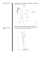
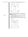
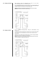
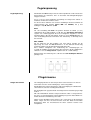
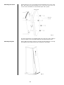
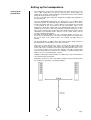
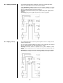
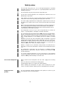
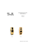
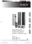
V 1.0 BETRIEBSANLEITUNG USER MANUAL CWT 2000 CWT 1000 CWT 500 Bestell-Nr./Order no. 9103 - 0440 2 Seite / Page Deutsch 4 English 16 Technische Daten / Specifications 29 3 Willkommen. Wir freuen uns, dass Sie sich für ein -Produkt entschieden haben. Mit Ihren neuen Solitaire CWT Lautsprechern haben Sie HiFi-Geräte der Spitzenklasse erworben, bei dessen Konzeption und Entwicklung den Wünschen des audiophilen Musikliebhabers oberste Priorität eingeräumt wurde. Die innovativen Problemlösungen, die solide, durchdachte Konstruktion und die verwendeten hochwertigen Materialien werden dazu beitragen, dass diese Lautsprecher höchsten Anforderungen und Ansprüchen über viele Jahre genügen werden. Eine genaue Qualitätsprüfung aller Materialien, die sorgfältige Produktion durch hochqualifizierte Fachkräfte und eine rechnergesteuerte, vollautomatisierte Endkontrolle gewährleisten die hohe Produktqualität und die Einhaltung aller Spezifikationen. Seit 1984 entwickelt und produziert die SOLITAIRE Lautsprecherserie. CWT steht für Cylinder Wave Transducer. Die drei CWT-Modelle entsprechen dieser Tradition. Sie sind reine High End Standlautsprecher, die kompromisslos völlig neu entwickelt wurden. Im Vordergrund stand die möglichst perfekte und ideale Musikwiedergabe. Die CWTModelle haben extrem aufwändige Gehäuse mit mehrschichtigem Aufbau erhalten, die äußerst fest, resonanzarm und stabil sind. Im Bassbereich wurde auf geschlossene Gehäuse gesetzt, um eine möglichst saubere Impulswiedergabe und niedrige untere Grenzfrequenz zu erreichen. Zur gänzlichen Vermeidung von Gehäuseresonanzen sind die Tieftöner impulskompensierend symmetrisch angeordnet worden. Für den Mitteltonbereich wurde ein völlig neues Chassis entwickelt, das nicht nur über eine unglaubliche Impulswiedergabe verfügt, sondern auch frei von allen Verfälschungen und Verfärbungen ist. Im Hochtonbereich kommt ein aufwändiger, völlig neu entwickelter Hochton-Elektrostat mit enormer Membranfläche zum Einsatz. Ein ideales Chassis für den gesamten Hochtonbereich. Das Ganze befindet sich in unvergleichlichen Gehäusen, deren Form perfekt für die benötigte Funktion geschaffen wurde und um absolute Resonanzfreiheit zu gewährleisten. Als Sonderzubehör sind hochwertige audiophile Kabel und Steckverbinder lieferbar. Wir bedanken uns für Ihr Vertrauen und wünschen Ihnen viel Freude und Hörvergnügen mit Ihren Solitaire CWT-Lautsprecherboxen. elektroakustik GmbH & Co KG Alle verwendeten Bauteile entsprechen den geltenden deutschen und europäischen Sicherheitsnormen und -standards. Zu Ihrer eigenen Sicherheit sollten Sie bitte unbedingt diese Betriebsanleitung vollständig lesen und insbesondere die Aufstellungs-, Betriebs- und Sicherheitshinweise genau befolgen. Dieses Produkt entspricht der Niederspannungsrichtlinie (2006/95/EG), der EMV-Richtlinie (2004/108/EG) und den CEMarkierungsrichtlinien (93/68/EG). 4 Inhalt Solitaire CWT Serie ................................................................................................... 6 Montage und Aufstellung .................................................................................................... • Lieferumfang ................................................................................................................ • Auspacken ................................................................................................................... • Montage ...................................................................................................................... • Aufstellung ................................................................................................................... • Anschluss ..................................................................................................................... • Verkabelung ................................................................................................................. 6 6 6 7 9 10 11 Pegelanpassung ................................................................................................................. Pflegehinweise ................................................................................................................... Sicherheitshinweise ........................................................................................................... Betriebsstörungen .............................................................................................................. Technische Daten .............................................................................................................. 13 13 14 15 29 In der Anleitung verwendete Symbole Achtung! Mit diesem Symbol gekennzeichnete Textstellen enthalten wichtige Hinweise, die für einen problemlosen und sicheren Betrieb des Gerätes unbedingt beachtet werden müssen. Symbol markiert Textpassagen, die Ihnen zusätzliche Hinweise und Hintergrundinformation geben Dieses und das Verständnis erleichtern sollen. 5 Solitaire CWT Serie CWT 2000 CWT 1000 CWT 500 Montage und Aufstellung Lieferumfang Zum Lieferumfang gehören die folgenden Einzelteile: • 2 Solitaire CWT Lautsprecher • 2 Abdeckgitter • 2 Sockelplatten • 2 Netzkabel • 8 Spikes • 8 Inbusschrauben • 8 Kunststofftüllen • 16 O-Ringe • Justagewerkzeug • 1 Flasche spezielle Politur • 1 Bedienungsanleitung Heben Sie bitte die Originalverpackung auf. Der Karton und das Verpackungsmaterial sind speziell für diese Lautsprecher konzipiert. Sie stellen einen sicheren Behälter für spätere Transporte dar und erhalten den Wiederverkaufswert der Lautsprecherboxen. Falls Sie die Verpackung nicht mehr benötigen, geben Sie diese Ihrem Händler zurück, um eine fachgerechte Entsorgung zu gewährleisten. Auspacken Öffnen Sie den Lautsprecherkarton senkrecht stehend und ziehen Sie den Lautsprecher nach vorne heraus. Legen Sie die Lautsprecher mit den Schaumstoffformteilen auf die Rückseite. 6 Montage Aus technischen Gründen sind die Sockelplatten und Abdeckgitter separat verpackt. Zur Montage gehen Sie wie folgt vor: Entfernen der Transportsicherung Entfernen Sie die vier Schrauben und die Transportplatte wie in Abbildung 1 dargestellt. Abb. 1 Montage der Spikes Um die Spikes vorübergehend mit einer definierten Höhe einzuschrauben, wird das Justagewerkzeug um das Gewinde eines Spikes gelegt und dieser soweit eingeschraubt bis sich das Justagewerkzeug gerade noch entfernen lässt (Abb. 2).Diesen Vorgang für alle Spikes wiederholen. Abb. 2 7 Montage des Sockels Die Schrauben mit jeweils 2 O-Ringen versehen und in die Bohrung der Bodenplatte einführen. Anschließend die Kunststofftülle auf die Schraube stecken und den Sockel anschrauben. Abb. 3 Die Lautsprecher senkrecht stellen und die Spikes ganz in das Gehäuse drehen um die Inbusschrauben zu entlasten und das Gehäuse zu entkoppeln. Montage des Schutzgitters Das Gitter in die Nut im Deckel einführen und anschließend vorsichtig von oben nach unten in die seitlichen Befestigungsnuten einführen. Abb. 4 8 Aufstellung Aufstellung Die Lautsprecher sind symmetrisch aufgebaut, das heißt, es gibt eine linke und eine rechte Box. Um die bestmögliche Wiedergabequalität zu erreichen sollten die Lautsprecher mit den Hochtonelektrostaten nach außen aufgestellt werden. Es empfiehlt sich außerdem, die Lautsprecher leicht auf den Hörplatz auszurichten. Die neuen SOLITAIRE® Lautsprecher sind als Cylinder Wave Transducer (CWT) konzipiert. Die Mitteltöner bilden ein so genanntes Line - Array und der Elektrostat eine Line - Source, durch die eine Bündelung des Schallfeldes zwischen Ober- und Unterkante des Lautsprechers erreicht wird. Oberhalb der Gehäuse und nach unten ist die Abstrahlung des gesamten Tief-Mittel und des Hochtonfrequenzbereichs gering. Damit gibt es auch sehr wenig Decken- und Bodenreflexionen und so gut wie keine Beeinflussungen des Klangbildes und Abbildungsverhaltens durch den Abhörraum. Die CWT sind leicht nach hinten geneigt, damit die Zylinderwelle in den Abhörraum hinein ansteigt. Beim Abhören sollte man sich also im Bereich vor den Schallwänden befinden, keinesfalls oberhalb der Gehäuse. Der Hörabstand sollte etwa 10% größer sein als der Abstand der Lautsprecher zueinander und 3,5 Meter nicht unterschreiten. Berücksichtigen Sie, dass die Basswiedergabe durch eine Positionierung der Boxen an der Wand um ca. 3 dB, in der Raumecke bis zu 6 dB angehoben wird. Zur Vermeidung einer überhöhten Bassabstrahlung ist es daher sinnvoll, die Boxen mit einem Abstand von mindestens 1 Meter zu den Seitenwänden möglichst frei aufzustellen (siehe Abschnitt "Pegelanpassung"). Stellen Sie die Boxen so auf, dass eine Berührung der Polklemmen im Betrieb, insbesondere durch Kinder, ausgeschlossen ist! 9 Anschluss Terminal Alle Solitaire CWT Modelle sind einem Bi-Wiring Anschlussterminal ausgestattet, welches für den Bassbereich (Bass) und den Mittel-/Hochtonbereich (Mid / High) getrennte Eingänge zur Verfügung stellt. Dieses Terminal erlaubt neben dem Standard-Anschluss auch die Betriebsarten Bi-Wiring und BiAmping. (siehe Verkabelung) Netzanschluss Elektrostaten benötigen eine Hochspannung für die Aufladung der Folie. Deshalb haben die CWT - Lautsprecher einen Netzanschluss und einen Netzschalter. Power ON LED Einschaltautomatik Das Netzteil für den Elektrostaten ist mit einer Einschaltautomatik ausgestattet. Wird ein Musiksignal erkannt schaltet es automatisch ein. Das -Logo am Lautsprecher ist gleichzeitig die Einschaltkontrolle (Power ON LED). Wenn der Lautsprecher eingeschaltet ist, leuchtet die Anzeige rot. Nach ca. 5 Minuten ohne Signal schaltet es automatisch wieder aus. Das Logo erlischt. (beleuchtetes -Logo) Es ist empfehlenswert, den Elektrostaten vor jedem Hören ca. 3 Minuten einlaufen zu lassen, damit sich die Elektrostatenfolie mit Ladungsträgern aufladen kann. Die CWT-Lautsprecher können an alle Verstärker angeschlossen werden, die für eine Lastimpedanz von 4 Ω ausgelegt sind. Verstärker Um das klangliche Potential dieser Lautsprecher voll zur Geltung zu bringen, empfehlen wir laststabile Endstufen mit hoher Stromlieferfähigkeit (>5 Ampere für CWT 500, >10 Ampere für CWT 1000 und CWT 2000) Kabel Anschlussklemmen und Lautsprecherkabel können gefährliche Spannungen führen! Vor Arbeiten an der Verkabelung ist der Verstärker unbedingt auszuschalten! Einen entscheidenden Einfluss auf den Klang der Gesamtanlage übt das verwendete Kabel aus. hat deshalb ein eigenes Kabelprogramm entwickelt, welches für jede Anwendung das passende Kabel beinhaltet. Diese Kabel sind auf die speziellen Eigenschaften unserer Lautsprecher abgestimmt. Alle verwendeten Kabel sollten gleich lang sein! 10 Beim Standard-Anschluss wird pro Box nur ein Lautsprecherkabel benötigt. Die Verbindungsbrücken zwischen Bass und Mid / High bleiben eingebaut Standard - Anschluss Bi - Wiring Im Bi – Wiring und Bi – Amping Betrieb müssen unbedingt die Kabelbrücken zwischen dem Tiefton (Bass)- und Mittel/Hochtoneingang (Mid / High) entfernt werden. Beim Bi-Wiring werden durch getrennte Signalführung der Bass- (Bass) und Mittel/Hochton-Signale (Mid / High) bessere klangliche Ergebnisse erzielt. Es werden pro Box zwei Lautsprecherkabel benötigt. An Endstufen mit zwei Lautsprecherausgängen ( A und B) werden die Boxen gemäß folgender Abbildung angeschlossen; bei Endstufen mit nur einem Lautsprecherausgang werden beide Kabel parallel an diesen Ausgang angeschlossen. 11 Bi – Amping (horizontal) Beim Bi-Amping werden die Signalwege des Tiefton- und des Mittel/Hochtonbereiches bereits vor der Endstufe getrennt. Bei der horizontalen Bi-Amping-Variante übernimmt eine Stereo-Endstufe die Verstärkung des Tieftonbereiches für beide Kanäle während die andere StereoEndstufe den Mittel-/Hochtonbereich beider Kanäle treibt. Vorteil: Symmetrische Auslastung des Endstufen-Netzteils für beide Kanäle. Nachteil: Die Endstufe bestimmt die Kanaltrennung. Bi – Amping (vertikal) Bei der vertikalen Bi-Amping-Variante erfolgt die Endverstärkung streng kanalgetrennt. Je eine Stereo-Endstufe übernimmt die Verstärkung einer Lautsprecherbox, indem der eine Kanal den Hoch-/Mitteltonbereich und der andere Kanal den Tieftonbereich treibt. Vorteil: Maximale Kanaltrennung im Endstufenbereich. Kurze Lautsprecherkabel durch lautsprechernahe Positionierung der Endstufen. Nachteil: Asymmetrische Auslastung des Endstufen-Netzteils durch Bassanteile einerseits und Mittel-/ Hochtonanteile andrerseits. 12 Pegelanpassung Pegelanpassung Alle Modelle der CWT-Lautsprecherserie können problemlos an die akustischen Eigenschaften des Hörraumes bzw. an besondere Aufstellungsbedingungen angepasst werden. So ist es z.B. bei einer wandnahen Aufstellung der Lautsprecher oftmals erforderlich, den Bassbereich abzusenken. Zu diesem Zweck befinden sich auf dem rückwärtigen Anschlussterminal der Lautsprecherbox drei Schalter (BASS, MID und TREBLE) mit je drei Stellungen: +1,5 dB, LIN und -1,5 dB BASS Für eine Aufstellung im Raum mit großem Abstand zur Wand (> 1,5 m) empfiehlt sich die Schalterstellung +1,5 dB. Bei einer wandnahen Aufstellung ergeben sich erfahrungsgemäß die besten klanglichen Ergebnisse mit der Schalterstellung 0 dB. Die Aufstellung der Box in einer Raumecke kann zu einer Überhöhung im Bassbereich führen. Die Einstellung -1,5 dB kompensiert diesen Effekt. MID / TREBLE Auf der Rückseite der Box befinden sich zwei weitere Schalter für die Anpassung des Hoch- und Mitteltonbereiches an den Hörraum. Werksseitig sind beide Schalter auf die Normalstellung 0 dB eingestellt. Diese Schalter ermöglichen eine Veränderung des Lautstärkepegels um ±1,5 dB. Als Richtlinie für die Einstellung dieser Bereiche gilt die Halligkeit des Hörraumes. Für sehr hallige Räume empfiehlt sich die -1,5 dB Stellung. Dagegen kann eine Anhebung um 1,5 dB bei sehr stark bedämpften Räumen günstiger sein. Pflegehinweise Pflege des Gerätes Vor Reinigungsarbeiten an den Lautsprechern ist der Netzstecker zu ziehen! Verwenden Sie keine scharfen Reinigungs- oder Lösungsmittel! Die Oberfläche der Lautsprechergehäuse sollte zur Reinigung ausschließlich mit einem weichen, trockenen Tuch abgewischt werden. Das Frontgitter kann gegebenenfalls vorsichtig mit einem Staubsauger gereinigt werden. Mit echten Edelhölzern furnierte Lautsprecherboxen sollten so aufgestellt werden, dass sie nicht der direkten Sonnenstrahlung ausgesetzt sind; Echtholz verändert durch Sonneneinwirkung seine Farbe. Sollten auf der Oberfläche leichte Kratzer sein, so benutzen Sie die beigelegte Politur. Tragen Sie diese mit einem weichen Tuch oder Watte in kreisenden Bewegungen dünn auf. Anschließend mit einem sauberen weichen Tuch nachpolieren. Sicherheitshinweise Bitte lesen Sie die Bedienungsanleitung vor Gebrauch der Anlage sorgfältig durch. Befolgen Sie unbedingt die folgenden Sicherheitsvorschriften! Die Lautsprecher dürfen nur in trockenen Räumen betrieben werden. Wie alle Elektrogeräte so sollte auch dieses Gerät nicht unbeaufsichtigt betrieben werden. Bei längerer Nichtbenutzung sollte der Netzstecker der Geräte aus der Steckdose gezogen werden. Die erforderliche Stromversorgung ist dem Aufdruck an der Lautsprecherrückwand zu entnehmen. An andere Stromversorgungen darf das Gerät nicht angeschlossen werden. Das Netzkabel muss so verlegt werden, dass keine Gefahr der Beschädigung (z. B. durch Trittbelastung oder durch Möbelstücke) besteht. Besondere Vorsicht ist dabei an den Steckern, Verteilern und an der Netz Eingangsbuchse der Boxen geboten. Auf den Netzstecker darf keine übermäßige Krafteinwirkung ausgeübt werden! Die Lautsprecher sind so aufzustellen, dass eine Berührung sämtlicher Geräteanschlüsse (insbesondere durch Kinder) ausgeschlossen ist. Der elektrostatische Hochtöner der Solitaire CWT Lautsprecher arbeitet mit sehr hoher Spannung. Alle Hochspannung führenden Teile sind durch Berührschutzgitter gesichert. Auf keinen Fall dürfen die Gitter entfernt werden. Bei der Berührung interner Teile des Elektrostaten besteht Lebensgefahr. Es dürfen keine Gegenstände durch die Gitter gesteckt werden. Das Eindringen von Flüssigkeiten in den Hochtöner ist unter allen Umständen zu vermeiden. Sollten doch Fremdkörper oder Flüssigkeiten in den Hochtöner gelangt sein, ist sofort der Netzstecker zu ziehen. Vor einer erneuter Inbetriebnahme ist die Lautsprecherbox in einer autorisierten Werkstatt überprüfen zu lassen. Außer den in der Bedienungsanleitung beschriebenen Handgriffen sollten vom Benutzer keinerlei Arbeiten am Gerät vorgenommen werden. Die Lautsprecher dürfen nur vom qualifizierten Fachmann geöffnet werden. Reparaturen und das Auswechseln von Sicherungen sind von einer autorisierten Fachwerkstatt durchzuführen. Bei Beschädigungen oder bei Verdacht auf eine nicht ordnungsgemäße Funktion der Geräte sollte sofort der Netzstecker gezogen, und die Geräte zur Überprüfung in eine autorisierte Fachwerkstatt gegeben werden. Vor Reinigungsarbeiten an den Lautsprechern ist der Netzstecker zu ziehen! Verwenden Sie keine scharfen Reinigungs- oder Lösungsmittel! Zum Polieren der Gehäuse ist ausschließlich die mitgelieferte Politur zu verwenden! Vor der Wiederinbetriebnahme muss sichergestellt sein, dass keine Kurzschlüsse an den Anschlussstellen bestehen und dass alle Anschlüsse ordnungsgemäß sind. Pflege der Lautsprecher Entsorgung der Lautsprecher Für die spätere Entsorgung dieses Produkts stehen örtliche Sammelstellen für Elektroschrott zur Verfügung. 14 Betriebsstörungen Viele Betriebsstörungen haben eine einfache Ursache, die sich leicht beheben lässt. Im folgenden Abschnitt sind einige mögliche Störungen sowie Maßnahmen zu deren Behebung aufgeführt. Sollte sich eine aufgetretene Störung durch diese Hinweise nicht beheben lassen, so ziehen Sie bitte umgehend den Netzstecker und wenden sich an eine -Fachwerkstatt. Kein Ausgangs-Signal oder stark verzerrtes Signal an den Lautsprechern . Ursache: Kurzschluss in den Lautsprecherkabeln; z.B. durch herausstehende Litzenenden an den Polklemmen oder mechanische Beschädigung des Kabels. Abhilfe: Lautsprecherkabel und Polklemmen überprüfen, Litzenenden sauber verdrillen (evtl. Adernendhülsen benutzen), beschädigte Kabel unbedingt austauschen! Flaches Klangbild, zu wenig Basswiedegabe Ursache: Die Lautsprecherleitungen sind verpolt angeschlossen Abhilfe: Den Anschluss der Lautsprecherleitungen an Boxen und Lautsprecherklemmen des Verstärkers anhand des Anschluss-Schemas überprüfen und ggf. korrigieren Zu kräftige oder dröhnende Basswiedergabe. Ursache: Die Box steht zu dicht an der Wand oder in einer Raumecke. Abhilfe: Halten Sie einen Mindestabstand von 50 cm zu den seitlichen Wänden oder ändern Sie die Schalterstellung "BASS" auf der Rückseite der Box. Keine Hochtonwiedergabe Ursache: Die Hochspannung für den elektrostatischen Hochtöner fehlt. Abhilfe: Schalten Sie den Netzschalter auf der Rückseite der Box in Stellung "ON". 15 Welcome. We are delighted that you have decided to purchase a product. With your new Solitaire CWT speakers you have acquired a top-quality piece of equipment which has been designed and developed with the wishes of the audiophile music lover as absolute top priority. All these factors contribute to a piece of equipment which will satisfy your highest demands and your most searching requirements for a period of many years. All the components we use meet the German and European safety norms and standards which are currently valid. All the materials we use are subject to painstaking quality monitoring. have been manufacturing and developing the SOLITAIRE series of loudspeakers since 1984. CWT stands for Cylinder Wave Transducer. The SOLITAIRE CWT series has been revised and expanded by the addition of three genuine High-End models which have been developed without compromise. The primary aim was always this: musical reproduction to the highest possible standard of fidelity. These CWT models are housed in extremely sophisticated cabinets made of multi-layer material which is extremely strong and rigid, and highly resistant to resonance. For the bass range we have chosen a large closed cabinet to get a low cut-off frequency and a perfect transient response. To avoid all acoustical resonances and to cancel all moving mass effects, the bass drivers are positioned symmetrically in opposite directions. For the mid-range we have developed a completely new driver, featuring incredible transient response and virtually complete freedom from coloration and distortion. For the treble range a completely new constructed electrostatic driver with a huge membrane area is used. It is an ideal driver for the whole treble range. All this technology is packed into cabinets of incomparable quality whose form follows the required function perfectly Our range of accessories includes high-quality cables and connectors. We would like to take this opportunity to thank you for the faith you have shown in our company by purchasing this product, and wish you many hours of enjoyment and sheer listening pleasure with your Solitaire CWT loudspeakers. elektroakustik GmbH & Co KG All the components we use meet the European safety norms and standards which are currently valid. The operation instructions, the connection guidance and the safety notes are for your own good - please read them carefully and observe them at all times. This product complies with the Low Voltage Directive (2006/95/EEC), EMV Directive (2004/108//EEC) and CE Marking Directive (93/68/EEC). 16 Contents Solitaire CWT series .................................................................................................. 18 Assembling and setting up ................................................................................................. • Package contents......................................................................................................... • Unpacking .................................................................................................................... • Mounting ...................................................................................................................... • Setting up the loudspeakers ........................................................................................ • Connections ................................................................................................................. • Wiring ........................................................................................................................... 18 18 18 19 21 22 23 Leveladjustment ................................................................................................................. Care maintenance .............................................................................................................. Safety notes ........................................................................................................................ Trouble shooting ................................................................................................................. Specifications ..................................................................................................................... 25 25 26 27 29 Symbols used in these instructions Caution! passages marked with this symbol contain important information which must be observed if the machine Text is to operate safely and without problems. symbol marks text passages which provide supplementary notes and background information; they are This intended to help the user understand how to get the best out of the device. 17 Solitaire CWT Series CWT 2000 CWT 1000 CWT 500 Assembling and setting up Package contents The package content consists of the following single parts: • 2 Solitaire CWT loudspeakers • 2 grilles • 2 socket-plates • 2 mains cables • 8 spikes • 8 Allen screws • 8 plastic bushings • 16 O-rings • Adjusting tool • 1 bottle special polish • 1 User manual Please store the original packaging materials in a safe place. The carton and packing materials have been specially designed for these loudspeakers. They form a safe container should you need to transport the speakers at any time, and they also help to maintain the speakers’ second-hand value. If you don’t wish to keep the packaging, give the material back to your supplier for appropriate disposal. Unpacking Open the carton in an upright position and pull out the loudspeaker. Put it down on its back with the packing-material. 18 Mounting For technical reasons the socket-plates and the grilles are packaged separately. Please assemble as follows: Removing the transport socket plate Remove the four screws of the transport-socket-plate and the plate itself as shown below.(fig.1) Fig. 1 Mounting the spikes Initially the spikes must be installed with a certain clearance between bottom plate of the loudspeaker and the spike. To achieve this, please use the adjusting tools as shown and insert it between spike and bottom plate. Screw in the spike by hand and tighten it only loosely so that you can still remove the distance tool easily. Fig. 2 19 Mounting the socket Fit two O-rings on every screw and insert them through the holes of the socket plate. After that fit the plastic-bushing on the screws and screw in the four screws in to the threaded inserts in the bottom plate of the speaker. Fig. 3 Set up the loudspeaker in an upright position and screw in the spikes totally to release the Allen screws and get the loudspeaker decoupled from the floor. Mounting the grille Put the grille in the groove of the top cover plate and after that push it carefully from top down to the bottom into the slots on both sides of the baffle. Fig. 4 20 Setting up the loudspeakers Setting up the loudspeakers The loudspeakers are designed symmetrically. This means that there is a left and a right loudspeaker. To get the best possible sound quality the loudspeakers should be positioned with the electrostatic tweeters at the outward facing side of the speakers (see fig. 5). It is also recommended to adjust the loudspeakers slightly angled inwards to your listening seat. The new SOLITAIRE® loudspeakers are designed to act as Cylinder Wave Transducers (CWT). The mid-range drivers form what is known as a Line Array, and the electrostatic unit a Line - Source, with the net result that the sound field is concentrated in the area between the top and bottom edges of the loudspeaker. Above the cabinet and in the downward direction the effective radiation of the speaker’s entire bass-mid-range and treble frequencies is low. This results in greatly reduced reflections from ceiling and floor, and the virtual elimination of the listening room’s influence on the sound image and the speaker’s imaging characteristics. The CWT are inclined slightly to the rear, so that the cylinder wave rises as it moves into the listening space. The listener should therefore be positioned in the area in front of the speaker baffles, and certainly not higher than the cabinets. The listening distance should be about 10% greater than the distance between the loudspeakers, and should be no less than 3.5 metres. Please bear in mind that the bass level is increased by about 3 dB if you position the speakers against a wall, and by up to 6 dB if you place them in the corner of the room. To avoid excessive bass response it therefore makes sense to set up the speakers at least 0.5 metres from the side walls of the listening room; if at all possible they should be free-standing, i.e. unobstructed by other furniture etc. (see „Level adjustment“ section). Hiding the loudspeakers behind furniture or curtains has a very marked adverse effect on their treble reproduction. Position the speakers in such a way that the terminals cannot be touched when the speakers are operating - especially by children! Fig. 5 21 Connections Terminals CWT loudspeakers are equipped with bi-wiring terminals which feature separate inputs for the bass range (Bass) and the mid-range/treble range (Mid / High). These terminals can be used for standard wiring arrangements, but also for the methods known as bi-wiring and bi-amping. (cp. wiring diagrams) Mains input The foil membrane of electrostatic drive units needs to be charged up using a high voltage, and that is why the CWT loudspeakers feature a mains inlet and a mains switch. Power ON LED Automatic switch on The power supply of the electrostatic tweeter is equipped with an automatic switch-on circuit. If a music signal is fed to the loudspeaker the power supply will switch on automatically. The illuminated -logo on the speaker baffle is turned on to show that the speaker is now switched ON and ready for operation. (illuminated logo) After about 5 minutes without any signal the speaker will shut down automatically and the logo will turn dark. We recommend that you should run-in the electrostatic drivers for about 3 minutes before listening to music, to give time for the electrostatic tweeters to charge up completely. CWT loudspeakers can be connected to any amplifier designed for a 4 Ohm speaker load. Amplifier However, if you wish to exploit the full sound potential of these speakers, we recommend power amplifiers which are capable stable of supplying high currents. (>5 Ampere for CWT 500,>10 Ampere for CWT 1000 und CWT 2000) Cable Loudspeaker binding posts and loudspeaker cables can carry dangerously high voltages. Be sure to switch off the amplifier before carrying out any wiring work. The cables employed in any Hi-Fi system have a crucial influence on the sound of the system as a whole. For this reason has developed its own range of cables which includes the ideal type for every application. These cables are designed to match the special characteristics of our loudspeakers. Please note that all the cables used should be the same length! 22 In the standard wiring arrangement only one speaker cable is required for each loudspeaker. The linking bridges between Bass and Mid / High must be left in place. Standard - connections Bi - Wiring In bi-wiring and bi-amping arrangements the cables bridging of the woofer (Bass) and mid/high (Mid/High) input terminals must be removed! Bi-wiring provides better sound by separating the bass (Bass) signal and midrange/treble signals (Mid/High). Two speaker cables are required for each loudspeaker. If your power amplifier has two loudspeaker outputs ( A and B), the speakers are connected as shown in the illustration below; If the power amplifier has outputs for only one pair of loudspeakers, connect both cables to these outputs in parallel. 23 Bi – amping (horizontal) In a bi-amping arrangement the signal paths for the bass and mid-range/treble ranges are separated before they reach the power amplifiers. In the horizontal bi-amping version, one stereo power amplifier is used to amplify the bass range for both channels, while a second stereo power amplifier drives the mid-range/treble range of both channels. Advantage: symmetrical load on the power amplifier mains power supply for both channels. Disadvantage: the power amplifier determines the channel separation. Bi – Amping (vertical) In the vertical bi-amping version the power amplifiers work in a strictly channelseparate arrangement. One stereo power amplifier amplifies the signals for one loudspeaker: one channel drives the treble/mid-range, the other channel the bass range. Advantage: maximum channel separation in the power amplifiers. Power amplifiers can be located close to the speakers, therefore short speaker leads can be used. Disadvantage: asymmetrical load on the power amplifier mains power supplies due to bass processing on one side and mid-range/treble processing on the other. 24 Level adjustment Level adjustment All models of the CWT loudspeaker series can easily be adjusted to suit the acoustic qualities of the listening room, or to particular conditions and speaker positions. For example, it may well be necessary to reduce the bass range if the speakers are set up close to a wall. To facilitate these adjustments you will find three switches (marked BASS, MID and TREBLE) on the rear terminal of the speaker cabinet; each switch has three positions: +1.5 dB, LIN and -1.5 dB. BASS If the loudspeakers are set up in a listening room a considerable distance from the walls (> 1.5 m) we recommend setting the switch to +1.5 dB. If the loudspeakers are set up in a listening room close to the walls, in our experience the best results in terms of sound are obtained with the switch set to 0 dB. If the loudspeakers are set up in one corner of the room, the result can be excessive bass emphasis. The -1.5 dB setting compensates for this effect. MID / TREBLE On the rear of each speaker you will also find two additional switches for adjusting the treble and mid-range response to suit the listening room. The default position for both switches is 0 dB. These switches enable you to adjust the level by +/- 1.5 dB, and the adjustment is designed to compensate for very „hard“ (highly reflective) or very „soft“ (highly damped) rooms. For rooms which tend to echo, we recommend the -1.5 dB setting. In contrast, a lift of 1.5 dB may be helpful in rooms which tend to damp sound down. Care and maintenance Care of the loudspeakers Always disconnect the loudspeakers from the mains supply before cleaning them. Never use powerful cleaning agents or solvent cleaners! The surface of the loudspeaker cabinets should be cleaned simply by wiping with a soft, dry cloth. If necessary, the front grille can also be cleaned carefully using a vacuum cleaner. Loudspeaker cabinets finished in genuine hardwood veneers should be set up in a location away from direct sunshine; real wood changes colour when subjected to sunlight. If there are slight scratches on the surface of your speaker-cabinet use the polish from the accessories of your CWT speaker. Apply it with a soft piece of cloth in circling movements. Then use a clean and dry cloth to finish the polishing process. Safety notes For your own safety please be sure to read right through these operating instructions before you use the system. It is especially important to observe the following safety notes. The loudspeakers may only be operated in a dry indoor room. Like any other electrical apparatus, these loudspeakers should never be used without proper supervision. If the speakers are not to be used for a long period, we recommend that you isolate them from the mains by pulling out the plug at the wall socket. The power supply required for these loudspeakers is printed on the rear face of the cabinet. The speakers must never be connected to any other form of power supply. Mains leads must be deployed in such a way that there is no danger of damage to them (e.g. through persons treading on them or from furniture). Take particular care with plugs, distribution panels and connections at the loudspeakers. Do not exert undue force on the mains connectors. The loudspeakers must be set up in such a way that there is no chance of anyone - especially children - touching the electrical connections. The electrostatic treble unit employed in the CWT, operate at very high voltage. All parts carrying high voltages are protected using contact guard grilles. These grilles must never be removed. Touching any internal parts of the electrostatic driver is highly dangerous, as the voltages present are capable of causing death. You must never push any object through the grilles. Avoid fluids of any kind getting inside the treble units or the valve output stage at all costs. However, if foreign bodies or liquids should get into the treble units, disconnect the speaker from the mains immediately. The speaker must then be checked by an authorised service centre before being used again. With the exception of the connections and procedures described in these instructions, no work of any kind may be carried out on the loudspeakers by the user. The loudspeakers should only ever be opened by a qualified technician. Repairs and fuse replacements should be entrusted to an authorised specialist workshop. If a speaker should be damaged, or if you suspect that it is not functioning correctly, immediately disconnect the mains plug at the wall socket and ask an authorised specialist workshop to check the unit. Always disconnect the loudspeakers from the mains supply before cleaning them. Never use abrasive or solvent-based cleaning agents. For polishing the cabinets use only the also delivered polish. Before switching the loudspeakers on again, check carefully that no shortcircuits exist at the terminals, and that you have not disturbed any connections. Care of the loudspeakers Disposing of this product The only permissible method of disposing of this product is to take it to your local collection centre for electrical waste. 26 Trouble shooting Many problems have a simple cause and a correspondingly simple solution. The following section describes a few difficulties you may encounter, and the measures you need to take to cure them. If you find it impossible to solve a problem with the help of these notes please disconnect the unit from the mains and ask your authorised specialist dealer for advice. No output signal, or seriously distorted signal at the loudspeakers. Cause: Short-circuit at the loudspeaker cables; e.g. through stray wire strands at the terminal clamps, or mechanical damage to the cables. Remedy: Check loudspeaker cables and terminals carefully, twist wire ends neatly (conductor sleeves can also be used); be sure to replace damaged cables! Flat sound image, insufficient bass response. Cause: The loudspeaker cables are connected with reversed polarity. Remedy: Check the speaker connections at the loudspeakers and at the amplifier’s speaker terminals, referring to the wiring diagram; correct if necessary. Excessive or booming bass response. Cause: The loudspeaker is set up too close to the wall or in one corner of the room. Remedy: Maintain a minimum distance of 50 cm to the side walls, or change the setting of the „BASS“ switch on the back of the speaker. No treble response Cause: The high voltage for the electrostatic treble units is not present. Remedy: Move the mains switch on the back of the speaker to the „ON“ position. 27 Notizen / Notes 28 Technische Daten / Specification CWT 2000 CWT 1000 CWT 500 3-Weg geschlossen 3-Way closed box 3-Weg geschlossen 3-Way closed box 3-Weg geschlossen 3-Way closed box Standbox Floor standing loudspeaker Standbox Floor standing loudspeaker Standbox Floor standing loudspeaker Nennbelastbarkeit [Watt] Nominal Power rating [Watt] 400 300 150 Musikbelastbarkeit [Watt] Music power rating [Watt] 600 450 300 4 4 4 23 – 40000 26 – 40000 28 - 40000 88 dB 88 dB 87 dB Bestückung Tiefton [mm] Bass drive unit [mm] 4 x 250 4 x 210 2 x 210 Bestückung Mittelton [mm] Mid-range drive unit [mm] 6 x 150 6 x 120 3 x 120 Bestückung Hochton [mm] High freq. drive unit [mm] 920 x 50 Elektrostat Electrostatic 920 x 50 Elektrostat Electrostatic 460 x 50 Elektrostat Electrostatic Trennfrequenzen [Hz] Crossover frequencies [Hz] 170 / 1900 190 / 2000 210 / 2100 Impedanz [Ohm] Impedance [Ohm] Übertragungsbereich [Hz] Frequency response [Hz] Empfindlichkeit (1 Watt/1 m) Sensitivity (1 Watt/1 m) Pegelsteller Level adjustment Tiefton, Mittelton und Hochton regelbar Variable bass, mid-range, treble Netzanschluss Mains connection EU Version: 220-230 V / 50 - 60 Hz US Version: 110-115 V / 50 - 60 Hz Abmessungen H x B x T cm Dimensions H x W x D Sockel Socket Gewicht [kg] Weight [kg] 161 x 35 x 50 cm 134 x 32 x 46 cm 110 x 30 x 38 cm 3 x 41 x 58 cm 3 x 38 x 54 cm 3 x 36 x 46 cm 119 kg 83 kg 53 kg Technische Änderungen vorbehalten. / We reserve the right to alter specifications. 29 elektroakustik GmbH & Co. KG Herford Deutschland * Germany