1
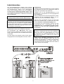
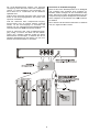
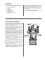
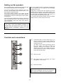
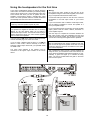
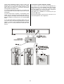
BETRIEBSANLEITUNG USER MANUAL TALIS AKTIV / ACTIVE TLS 20 A TLS 10 A V 1.0 Bestell-Nr./Order no. 9103-0343 2 Seite / Page Deutsch 4 English 12 Technische Daten / Specifications 19 3 Inhalt Auspacken ......................................................................................................................... Montagehinweise ............................................................................................................... Aufstellungshinweise ......................................................................................................... Bedienungs- und Anschlusselemente ............................................................................... Inbetriebnahme .................................................................................................................. • Verkabelung .................................................................................................................. • Anschluss an Endstufenausgänge ............................................................................... Sicherheitshinweise ........................................................................................................... Technische Daten .............................................................................................................. 4 5 5 6 6 7 7 8 9 19 Auspacken Bitte packen Sie die TALIS-Lautsprecher und das Zubehör vorsichtig aus. Zum Lieferumfang gehören die folgenden Einzelteile: • • • • • • • • • 2 2 2 6 6 6 1 2 1 Heben Sie die Originalverpackung zusammengefaltet auf. Der Karton und das Verpackungsmaterial sind speziell für diese Boxen konzipiert. Sie stellen einen sicheren Behälter für spätere Transporte dar und erhalten den Wiederverkaufswert der Lautsprecherboxen. TALIS-Lautsprechergehäuse Bodenplatten Zwischenböden Rosetten aus Kunststoff Rosetten aus Metall Senkkopfschrauben M6 Bedienungsanleitung Netzkabel Garantiekarte Falls Sie die Verpackung nicht mehr benötigen, geben Sie diese Ihrem Händler zurück, um eine fachgerechte Entsorgung zu gewährleisten. Montagehinweise Zu den TALIS-Lautsprechern TLS 20A und TLS 10A werden Bodenplatten mitgeliefert. Vor der Inbetriebnahme müssen diese Bodenplatten an die Lautsprecher montiert werden, um ausreichend Standsicherheit zu erhalten. Falls Sie sich für Bodenplatten aus Glas entschieden haben, ist es erforderlich, sehr vorsichtig damit umzugehen. Um Bruch zu vermeiden, sollten die Glasplatten nicht geworfen oder auf die Ecken gestoßen werden. Zur Montage ist der Lautsprecher kopfüber auf eine nicht kratzende Unterlage zu stellen. Der Zwischenboden und die Glasplatte werden vorsichtig so aufgelegt, dass die Montagelöcher übereinander liegen. Die Schrauben werden zusammen mit den Rosetten (siehe Zeichnung) nur leicht von Hand angeschraubt, um das Glas nicht zu beschädigen. Nach Montage der Glasplatte wird der Lautsprecher wieder herumgedreht und ist spielbereit. Die Glasplatten sind rückseitig mit einer Farbfolie beschichtet. Wird diese Folie beschädigt, so werden die Kratzer auf der Oberseite sichtbar. Bei der Aufstellung der Lautsprecher sollten diese niemals über den Boden geschoben werden, um Kratzer auf der Unterseite der Glasplatten zu vermeiden. Die Lautsprecher der TALIS-Serie werden mit einer Frontabdeckung ausgeliefert. Diese besteht aus einem mit Vlies hinterlegten Gitter. Es dient dem Schutz der Lautsprecherchassis. Die Gitter können und sollten nicht entfernt werden. Sie sind Bestandteil des akustischen Systems. Eine Entfernung führt zur Beschädigung der Gitter und zu einer Verschlechterung des Klangbildes. 5 Aufstellungshinweise Die beiden Lautsprecher sind durch einen Aufkleber als rechte bzw. linke Box gekennzeichnet. Sie sind durch ihre interne Beschaltung so festgelegt. Der Centerlautsprecher besitzt magnetisch abgeschirmte Lautsprecherchassis. Er kann in unmittelbarer Nähe zum TV-Gerät betrieben werden. Die beiden Frontlautsprecher sollten so platziert sein, dass die Entfernung zwischen den Boxen und die zum Hörer ungefähr ein gleichseitiges Dreieck bildet. Berücksichtigen Sie, dass die Basswiedergabe durch eine Positionierung der Boxen an der Wand um ca. 3 dB, in der Raumecke bis zu 6 dB angehoben wird. Der minimale Hörabstand sollte 2 Meter nicht unterschreiten. Daraus ergibt sich nach der o. g. Dreiecksregel ein Mindestabstand der Lautsprecher zueinander von 2 Metern. Bei zu starker Basswiedergabe sollten die Lautsprecher etwas aus der Ecke bzw. von der Wand abgerückt werden. Die TALIS Standlautsprecher sollten in einem Abstand von mindestens 1,50 Meter vom TV-Gerät aufgestellt werden, da es sonst unter Umständen zu Farbveränderungen des Bildes führen kann. Hinweis: Für die Aufstellung in unmittelbarer Nähe eines TV-Gerätes sind die TALIS-Standlautsprecher optional mit abgeschirmten Chassis erhältlich. Bedienungs- und Anschlusselemente Schalter des internen Filters für den Tiefbassbereich. Werden die TALIS-Aktivboxen mit einem zusätzlichen Subwoofer betrieben, so sollte das Filter auf ON stehen. Dadurch werden sehr tieffrequente Musikanteile herausgefiltert, um die Belastbarkeit der Lautsprecher zu erhöhen. Ohne zusätzlichen Subwoofer sollte das Filter auf OFF stehen, um auch Tiefbassanteile zu übertragen. DIN-Eingangsbuchse. DIN-Ausgangsbuchse zum Anschluss 2. Lautsprechers oder eines Subwoofers. Netz Eingangsbuchse. des Achtung: Die TALIS-Aktivlautsprecher dürfen nur an einer dem Aufdruck entsprechenden Netzspannung betrieben werden. 6 Inbetriebnahme Die TALIS-Aktivlautsprecher besitzen einen internen elektronischen Netzschalter. Die Aktivierung erfolgt über eine Schaltspannung, welche an der DIN-Eingangsbuchse (Pin 4) angelegt werden muss. Das Quellgerät, mit dem Sie die Lautsprecher betreiben wollen, muss eine entsprechende DIN-Ausgangsbuchse besitzen. Wird das Quellgerät eingeschaltet, so aktivieren sich automatisch die Aktivboxen. Verkabelung: Verbinden Sie zuerst die Netzbuchsen auf der Rückseite der Lautsprecher mit Hilfe der mitgelieferten Kabel mit jeweils einer geschalteten Netz-Steckdose. Verbinden Sie nun die DIN-Eingangsbuchse an der Rückseite des 1. Lautsprechers mit der Ausgangsbuchse Ihres Quellgerätes. Falls Ihr Quellgerät keine DIN-Ausgangsbuchse besitzt, verwenden Sie den mitgelieferten Adapter zum Anschluss an einen Cinch Vorverstärker-Ausgang. Hinweis: In Standby Betrieb verbraucht die Box keine Leistung. Sollte ein Cinch Vorverstärker-Ausgang an Ihrem Quellgerät nicht vorhanden sein, so lesen Sie bitte im Abschnitt 'Anschluss an Endstufenausgänge' nach. Hinweis: Für Geräte, die über keine geschaltete DIN-Ausgangsbuchse verfügen, ist im Zubehör ein Adapter enthalten. Er besitzt einen Klinkenstecker, an welchem eine Spannung zwischen +5 und +20 V angelegt werden muss, um die Lautsprecher einzuschalten. Als nächstes muss eine Verbindung zwischen der DINAusgangsbuchse des 1. Lautsprechers mit der Eingangsbuchse des 2. Lautsprechers hergestellt werden. Verwenden Sie dazu das zweite mitgelieferte DIN-Verbindungskabel. Bei -Geräten ohne DIN-Ausgangsbuchse wird dieser Klinkenstecker mit der CTRL-Out-Buchse verbunden. Hinweis: Bei Fremdgeräten oder -Geräten ohne CTRLBuchse muss ein Schaltspannungsausgang nachgerüstet werden. Bitte wenden Sie sich in diesem Falle an Ihren Fachhändler. Die beiden Lautsprecher sind durch einen Aufkleber als rechte bzw. linke Box gekennzeichnet. Ob Sie als 1. Lautsprecher der Verbindungsreihenfolge die rechte oder linke Box verwenden, beeinflusst die Funktion der Lautsprecher nicht. Die Cinch Stecker des Adapters müssen mit den SignalAusgangsbuchsen des Quellgerätes verbunden werden. Hiermit ist die Verkabelung abgeschlossen. Die Lautsprecher sind nun spielbereit. Wenn Sie nun die Netzspannung einschalten, so schalten sich automatisch die TALIS-Aktivlautsprecher ein. Dieser Zustand wird Ihnen durch eine grüne Leuchtdiode hinter dem Gitter am unteren Teil der Front angezeigt. 7 Anschluss an Endstufenausgänge Die TALIS-Aktivlautsprecher besitzen eine Einschaltverzögerung. Diese dient dem Schutz der Lautsprecherchassis vor Spannungsspitzen beim Einschalten. Dadurch dauert es ca. 10 Sekunden bis die Aktivboxen spielbereit sind. Wenn Sie die TALIS Aktivlautsprecher an ein Quellgerät (z. B. Endstufe) ohne passende Cinch Ausgänge anschließen wollen, benötigen Sie eine zusätzliche Adapterbox. Damit ist es möglich, die Aktivlautsprecher an den Lautsprecherausgang eines Quellgerätes anzuschließen. Falls Sie einen Subwoofer integrieren wollen, können Sie diesen an die DIN-Ausgangsbuchse des zweiten Lautsprechers anschließen. Diese Adapterbox ist als Zubehör beim -Fachhändler erhältlich. Falls der Subwoofer keine entsprechende Eingangbuchse besitzt, kann ein weiterer Adapter verwendet werden, um die Cinch-Eingänge zu verwenden. Der Adapter und das entsprechende DIN-Verbindungskabel sind als Zubehör beim -Fachhändler erhältlich. Wie in diesem Falle die Geräte miteinander zu verkabeln sind, ist in folgendem Bild zu sehen: Wenn Ihr Subwoofer über einen Schaltspannungseingang verfügt, so können Sie diesen mit dem Klinkenstecker des 2. Adapters verbinden. Sollten Sie diesen Klinkenstecker nicht benötigen, so belassen Sie die mitgelieferte Abdeckkappe auf dem Stecker, um evtl. Kurzschlüsse mit anderen Geräten zu vermeiden. 8 Sicherheitshinweise Bitte lesen Sie die Bedienungsanleitung vor Gebrauch der Anlage sorgfältig durch. Befolgen Sie unbedingt die folgenden Sicherheitsvorschriften! 9. Die Lautsprecher sind so aufzustellen, dass eine Berührung sämtlicher Geräteanschlüsse (insbesondere durch Kinder) ausgeschlossen ist. 1. Die Aktivlautsprecher dürfen nur in trockenen Räumen betrieben werden. Es ist darauf zu achten, dass sie für kleine Kinder unerreichbar sind. 10. Außer den in der Bedienungsanleitung beschriebenen Handgriffen sollten vom Benutzer keinerlei Arbeiten am Gerät vorgenommen werden. 2. Es dürfen keine Flüssigkeiten oder Fremdkörper in das Gerät gelangen. Sollte dennoch eine Flüssigkeit oder ein Fremdkörper in das Gerät gelangt sein, ziehen Sie sofort den Netzstecker und lassen das Gerät in einer autorisierten Fachwerkstatt überprüfen! 11. Die Lautsprecher dürfen nur vom qualifizierten Fachmann geöffnet werden. Reparaturen und das Auswechseln von Sicherungen sind von einer autorisierten Fachwerkstatt durchzuführen. 12. Bei Beschädigungen oder bei Verdacht auf eine nicht ordnungsgemäße Funktion der Geräte sollte sofort der Netzstecker gezogen, und die Geräte zur Überprüfung in eine autorisierte Fachwerkstatt gegeben werden. 3. Wie alle Elektrogeräte, so sollten auch diese Aktivboxen nicht unbeaufsichtigt betrieben werden. 4. Bei längerer Nichtbenutzung sollte der Netzstecker der Geräte aus der Steckdose gezogen werden. 13. Pflege des Gerätes. 5. Waren die Aktivlautsprecher größerer Kälte ausgesetzt (z. B. beim Transport), so ist mit der Inbetriebnahme zu warten, bis sie sich auf Raumtemperatur aufgewärmt haben und das Kondenswasser restlos verdunstet ist. • Vor Reinigungsarbeiten an den Lautsprechern ist der Netzstecker zu ziehen! 6. Beim Aufstellen ist darauf zu achten, dass die Kühlluftzufuhr zum Gehäuse nicht behindert wird. • Vor der Wiederinbetriebnahme muss sichergestellt sein, dass keine Kurzschlüsse an den Anschlussstellen bestehen und dass alle Anschlüsse ordnungsgemäß sind. • Verwenden Sie keine scharfen Reinigungs- oder Lösungsmittel! Ein Wärmestau beeinträchtigt die Lebensdauer des Gerätes und ist eine Gefahrenquelle! 7. Die erforderliche Stromversorgung ist dem Aufdruck an der Lautsprecherrückwand zu entnehmen. An andere Stromversorgungen darf das Gerät nicht angeschlossen werden. 8. Das Netzkabel muss so verlegt werden, dass keine Gefahr der Beschädigung (z. B. durch Trittbelastung oder durch Möbelstücke) besteht. Besondere Vorsicht ist dabei an den Steckern, Verteilern und an der Netz Eingangsbuchse der Boxen geboten. Auf den Netzstecker darf keine übermäßige Krafteinwirkung ausgeübt werden! 9 Eine Entsorgung dieses Produkts darf nur über die Sammelstelle für Elektroschrott erfolgen. 10 English 11 Contents Unpacking .......................................................................................................................... Assembling the speakers ................................................................................................... Setting up the speakers ..................................................................................................... Controls and connections .................................................................................................. Using the speakers for the first time .................................................................................. • Wiring ............................................................................................................................ • Connection to power amplifier outputs ......................................................................... Safety notes ....................................................................................................................... Specification ....................................................................................................................... 12 11 11 12 12 13 13 16 14 19 Unpacking Please unpack your TALIS loudspeakers and accessories very carefully. The contents of the set are as follows: • • • • • • • • 2 2 2 6 6 6 1 2 Fold up the original packaging and store it in a safe place. The carton and packing materials have been specially designed for these loudspeakers. They form a safe container should you need to transport the speakers at any time, and they also help to maintain the speakers’ second-hand value. TALIS loudspeaker cabinets base plates spacers plastic spreaders metal spreaders M6 countersunk screws set of operating instructions mains leads If you don’t wish to keep the packaging, give the material back to your supplier for appropriate disposal. Assembling the speakers TALIS TLS 20A and TLS 10A loudspeakers are supplied with separate base plates. The base plates must be attached to the cabinets before you use the speakers to ensure that they are stable when erected. If you have purchased glass base plates please be extremely careful with them to avoid breaking the glass. Don’t drop or throw the glass plates, and take care not to hit the edges and corners on any hard object. To assemble the loudspeakers stand them on a surface which will not cause scratches and turn them upside-down. Carefully place the spacer and the glass plate on the cabinet bottom and line up the screw-holes. Fit the screws and the spreaders (see drawing), and tighten the screws gently. Tighten them by hand only to avoid damaging the glass. Carefully turn the speaker the right way up once the glass plate has been fitted; it is now ready for use. The reverse face of the glass plates is coated with a coloured film. Take care not to damage this film as any scratches will be visible on the top surface. When positioning the loudspeakers never push them along the floor as this will scratch the underside of the glass plates. TALIS series loudspeakers are supplied with a front cover. This consists of a grille lined with a fibrous material, and is designed to protect the drive units. The grilles cannot and must not be removed, as they are an integral part of the loudspeakers’ acoustic system. Any attempt at removal will damage the grilles and have an adverse effect on the sound image. 13 Setting up the speakers Each loudspeaker bears a sticker denoting the left and right unit. They are internally wired for this configuration. The centre speaker features magnetically shielded drive units as standard, and can safely be used immediately adjacent to the TV set. The two front speakers should be positioned in such a way that they and the listener form the three points of an approximately equi-lateral triangle. Please bear in mind that the bass response of the loudspeakers varies according to their position relative to the wall. Placing them against a wall raises the bass response by about 3 dB, and positioning them in the corners of a room increases bass response by about 6 dB. The minimum listening distance is two metres, and this should always be observed. This means that the speakers should also be at least two metres apart in order to satisfy the triangle rule. If you find the bass response excessive, move the speakers slightly out of the corners or away from the wall. TALIS floor-standing loudspeakers should be positioned at least 1.50 metres from your TV set, otherwise they could cause discoloration of the screen image under unfavourable circumstances. Note: As an option TALIS floor-standing speakers are available fitted with shielded drive units, should you wish to position immediately adjacent to your television. Controls and connections Internal filter switch for the low bass range. If you intend to operate the TALIS active speakers in conjunction with a separate sub-woofer, the filter should be set to ON. This filters out the extreme low-frequency part of the music signal, and thereby increases the speakers’ maximum load capacity. The filter should be set to OFF if your system does not include a separate sub-woofer, so that the speakers transmit the full bass range. DIN input socket. DIN output socket for connecting the second loudspeaker or a sub-woofer. Mains input socket. Caution: TALIS active loudspeakers must only be connected to a mains supply which satisfies the printed specification. 14 Using the loudspeakers for the first time TALIS active loudspeakers feature an internal electronic mains switch. The switch is activated by a switching voltage which must be present at pin 4 of the DIN input socket. The source device with which you wish to operate the loudspeakers must therefore include a suitable DIN output socket. The active speakers will then activate themselves automatically when the source device is switched on. Wiring: Note: If your source device does not feature a DIN output socket, use the adaptor (supplied) to connect the speaker to a Cinch pre-amplifier output. First connect the mains sockets on the rear face of the loudspeakers using the mains leads supplied; connect each plug to a separate switched mains outlet socket. Connect the DIN input socket on the rear face of the first loudspeaker to the DIN output socket of your source device. In stand-by mode the speakers require no power. Note: If your source device does not include a Cinch pre-amplifier output, please read the section entitled „Connection to power amplifier outputs“. The speakers are supplied as standard with an accessory adaptor for use with devices which do not feature a switched DIN output socket. This includes a barrel plug to which a voltage in the range +5 to +20 V must be applied in order to switch on the speakers. The next step is to complete the connection between the DIN output socket of the first loudspeaker and the input socket of the second speaker. This is carried out using the second DIN connecting lead supplied with the speakers. If you are using a device without a DIN output socket, connect the barrel plug to the CTRL-Out socket. Note: If you are using a different make of device, or a unit without a CTRL socket, it will be necessary to retro-fit a switching voltage output. Please ask your specialist dealer for details of this. The two loudspeakers bear stickers marked left and right. You can use the right or left speaker as the first unit in the connection sequence; this has no influence on the operation of the loudspeakers. The Cinch plugs attached to the adaptor must be connected to the signal output sockets of the source device. This completes the wiring process, and the speakers are ready for use. If you now switch on the source device, the TALIS active loudspeakers will switch themselves on automatically. A green LED lights up to indicate the ready status. The LED is located behind the grille on the lower part of the front panel. 15 Connection to power amplifier outputs TALIS active loudspeakers feature a power-on delay. The purpose of this is to protect the drive units from voltage surges which occur when power is initially switched on. The delay is about ten seconds, i. e. you have to wait until the active speakers are ready to work. If you wish to connect your TALIS active loudspeakers to a source device (e. g. power amplifier) which does not have suitable Cinch outputs, you will require a separate adaptor box. This enables you to connect the active loudspeakers to the loudspeaker output of a source device. If you wish to integrate a sub-woofer into your system, this can be connected to the DIN output socket of the second loudspeaker. This adaptor box is available as an accessory from your specialist dealer. If the sub-woofer does not feature a corresponding input socket, you can use the Cinch inputs with the help of a second adaptor. The adaptor and matching DIN connecting lead are available as accessories from your specialist dealer. The following diagram shows how the units have to be connected together in this configuration: If your sub-woofer features a switching voltage input, you can connect this to the barrel plug attached to the second adaptor. If you don’t need to use the barrel plug, leave the plastic cap on it to avoid possible short-circuits with other devices. 16 Safety notes For your own safety please be sure to read right through these operating instructions before you use the system. It is especially important to observe the following safety notes. 9. 1. The active loudspeakers may only be operated in a dry indoor room. Ensure that they are kept out of the reach of small children. 10. With the exception of the connections and procedures described in these instructions, no work of any kind may be carried out on the loudspeakers by the user. 2. Do not allow any liquid or foreign bodies to enter the speakers. If any liquid or foreign body should penetrate the cabinet despite your best efforts, immediately disconnect the mains plug at the wall socket, and have the unit checked by an authorised service workshop. 11. The loudspeakers should only ever be opened by a qualified technician. Repairs and fuse replacements should be entrusted to an authorised specialist workshop. 3. These active loudspeakers should never be operated without proper supervision. This applies to all electrical equipment. 4. If the speakers are not to be used for a long period, we recommend that you isolate them from the mains by pulling out the plug at the wall socket. 5. 6. 12. If a speaker should be damaged, or if you suspect that it is not functioning correctly, immediately disconnect the mains plug at the wall socket and ask an authorised specialist workshop to check the unit. 13. Care of the loudspeakers • Always disconnect the loudspeakers from the mains supply before cleaning them. If the active loudspeakers get very cold (e. g. when being transported) condensation may form inside them. Please do not switch them on until they have had plenty of time to warm up to room temperature, so that any condensation evaporates completely. • Never use abrasive or solvent-based cleaning agents. • Before switching the loudspeakers on again, check carefully that no short-circuits exist at the terminals, and that you have not disturbed any connections. When setting up the speakers, ensure that there is an unhindered flow of cooling air to and around the cabinets. Any heat build-up will shorten the life of the speakers, and could be a source of danger! 7. The power supply required for these loudspeakers is printed on the rear face of the cabinet. The speakers must never be connected to any other form of power supply. 8. The mains leads must be deployed in such a way that there is no danger of damage from furniture, or from people treading on them. Take particular care with plugs, distribution panels and the mains input sockets on the speakers. Never exert undue force on the mains plugs. The loudspeakers must be set up in such a way that there is no chance of anyone - especially children touching the electrical connections. 17 The only permissible method of disposing of this product is to take it to your local collection centre for electrical waste. 18 Technische Daten / Specification 2 ½-Wege vollaktiver Lautsprecher mit 3 Gegentakt-Leistungsendstufen und aktiver Frequenzweiche 2 ½-way fully active loudspeaker with three push-pull power amplifiers and active cross-over TLS 20 A TLS 10 A Eingangsempfindlichkeit für Vollaussteuerung / Input sensitivity for full output 1 Veff Eingangsimpedanz / Input impedance 10 kΩ Nennleistung / Nominal output 3 x 60 W Impulsleistung / Peak output 3 x 100 W Einschaltverzögerung / Power-on delay Leistungsaufnahme / Power consumption 10 s Maximal / maximum 200 W 250 W Klirrfaktor / Total harmonic distortion <0,02 % Geräuschspannung / Noise floor (A wighted) 150 µV Geräuschspannungsabstand / Signal : noise ratio >100 dB Bestückung Hochton / High-frequency drive unit 1 x 20 mm 1 x 35 mm Bestückung Tief-u. Mittelton / Bass / mid-range drive units 3 x 80 mm 4 x 140 mm Übertragungsbereich / Frequency response 40 Hz – 45 kHz 28 Hz – 45 kHz Trennfrequenzen / Cross-over frequencies (250), 2000 Hz (250), 2500 Hz Technische Änderungen vorbehalten. / We reserve the right to alter specifications. 19 elektroakustik GmbH & Co. KG Herford Deutschland * Germany