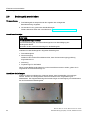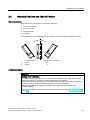
1
German
SIMATIC HMI HMI devices MP 277 INOX 10" Touch, MP 377 INOX 15" Touch
SIMATIC HMI
HMI devices
MP 277 INOX 10" Touch,
MP 377 INOX 15" Touch
Betriebsanleitung (kompakt)
Operating Instructions (Compact)
This documentation is valid for the products with the
order number:
6AV6643-0ED01-2AX0
6AV6644-0CB01-2AX0
01/2009
A5E02274759-02
A
______________
B
English
______________
______________
______________
MP 277 INOX 10" Touch, MP 377 INOX 15" Touch
Operating Instructions (Compact), 01/2009, A5E02274759-02
Sicherheitshinweise und
Zulassungen
SIMATIC HMI Bediengeräte MP 277 INOX 10" Touch, MP 377 INOX 15" Touch
SIMATIC HMI
Bediengeräte
MP 277 INOX 10" Touch
MP 377 INOX 15" Touch
Betriebsanleitung (kompakt)
Diese Dokumentation ist gültig für die Liefereinheiten
mit der Bestellnummer:
6AV6643-0ED01-2AX0
6AV6644-0CB01-2AX0
01/2009
A5E02274759-02
1
______________
2
Einbauen und anschließen
______________
3
Warten und instand halten
______________
4
Technische Angaben
______________
Rechtliche Hinweise
Rechtliche Hinweise
Warnhinweiskonzept
Dieses Handbuch enthält Hinweise, die Sie zu Ihrer persönlichen Sicherheit sowie zur Vermeidung von
Sachschäden beachten müssen. Die Hinweise zu Ihrer persönlichen Sicherheit sind durch ein Warndreieck
hervorgehoben, Hinweise zu alleinigen Sachschäden stehen ohne Warndreieck. Je nach Gefährdungsstufe
werden die Warnhinweise in abnehmender Reihenfolge wie folgt dargestellt.
GEFAHR
bedeutet, dass Tod oder schwere Körperverletzung eintreten wird, wenn die entsprechenden
Vorsichtsmaßnahmen nicht getroffen werden.
WARNUNG
bedeutet, dass Tod oder schwere Körperverletzung eintreten kann, wenn die entsprechenden
Vorsichtsmaßnahmen nicht getroffen werden.
VORSICHT
mit Warndreieck bedeutet, dass eine leichte Körperverletzung eintreten kann, wenn die entsprechenden
Vorsichtsmaßnahmen nicht getroffen werden.
VORSICHT
ohne Warndreieck bedeutet, dass Sachschaden eintreten kann, wenn die entsprechenden
Vorsichtsmaßnahmen nicht getroffen werden.
ACHTUNG
bedeutet, dass ein unerwünschtes Ergebnis oder Zustand eintreten kann, wenn der entsprechende Hinweis
nicht beachtet wird.
Beim Auftreten mehrerer Gefährdungsstufen wird immer der Warnhinweis zur jeweils höchsten Stufe verwendet.
Wenn in einem Warnhinweis mit dem Warndreieck vor Personenschäden gewarnt wird, dann kann im selben
Warnhinweis zusätzlich eine Warnung vor Sachschäden angefügt sein.
Qualifiziertes Personal
Das zugehörige Gerät/System darf nur in Verbindung mit dieser Dokumentation eingerichtet und betrieben
werden. Inbetriebsetzung und Betrieb eines Gerätes/Systems dürfen nur von qualifiziertem Personal
vorgenommen werden. Qualifiziertes Personal im Sinne der sicherheitstechnischen Hinweise dieser
Dokumentation sind Personen, die die Berechtigung haben, Geräte, Systeme und Stromkreise gemäß den
Standards der Sicherheitstechnik in Betrieb zu nehmen, zu erden und zu kennzeichnen.
Bestimmungsgemäßer Gebrauch von Siemens-Produkten
Beachten Sie Folgendes:
WARNUNG
Siemens-Produkte dürfen nur für die im Katalog und in der zugehörigen technischen Dokumentation
vorgesehenen Einsatzfälle verwendet werden. Falls Fremdprodukte und -komponenten zum Einsatz kommen,
müssen diese von Siemens empfohlen bzw. zugelassen sein. Der einwandfreie und sichere Betrieb der
Produkte setzt sachgemäßen Transport, sachgemäße Lagerung, Aufstellung, Montage, Installation,
Inbetriebnahme, Bedienung und Instandhaltung voraus. Die zulässigen Umgebungsbedingungen müssen
eingehalten werden. Hinweise in den zugehörigen Dokumentationen müssen beachtet werden.
Marken
Alle mit dem Schutzrechtsvermerk ® gekennzeichneten Bezeichnungen sind eingetragene Marken der Siemens
AG. Die übrigen Bezeichnungen in dieser Schrift können Marken sein, deren Benutzung durch Dritte für deren
Zwecke die Rechte der Inhaber verletzen kann.
Haftungsausschluss
Wir haben den Inhalt der Druckschrift auf Übereinstimmung mit der beschriebenen Hard- und Software geprüft.
Dennoch können Abweichungen nicht ausgeschlossen werden, so dass wir für die vollständige Übereinstimmung
keine Gewähr übernehmen. Die Angaben in dieser Druckschrift werden regelmäßig überprüft, notwendige
Korrekturen sind in den nachfolgenden Auflagen enthalten.
Siemens AG
Industry Sector
Postfach 48 48
90026 NÜRNBERG
DEUTSCHLAND
A5E02274759-02
Ⓟ 01/2009
Copyright © Siemens AG 2009.
Änderungen vorbehalten
Inhaltsverzeichnis
1
2
3
4
Sicherheitshinweise und Zulassungen....................................................................................................... 7
1.1
Gültigkeit ........................................................................................................................................7
1.2
Sicherheitshinweise .......................................................................................................................7
1.3
Normen und Zulassungen..............................................................................................................8
1.4
Einsatzhinweise ...........................................................................................................................11
1.5
Elektromagnetische Verträglichkeit .............................................................................................13
1.6
Transport- und Lagerungsbedingungen ......................................................................................15
Einbauen und anschließen ...................................................................................................................... 17
2.1
Einbauhinweise ............................................................................................................................17
2.2
Umgebungsbedingungen.............................................................................................................17
2.3
Einbaulagen und Befestigungsart................................................................................................18
2.4
Einbau vorbereiten.......................................................................................................................20
2.5
Bediengerät einbauen..................................................................................................................21
2.6
Bediengerät anschließen .............................................................................................................24
2.7
Potenzialausgleich anschließen...................................................................................................25
2.8
Stromversorgung anschließen .....................................................................................................26
Warten und instand halten ....................................................................................................................... 27
3.1
Warten und pflegen......................................................................................................................27
3.2
Chemische Beständigkeit ............................................................................................................29
3.3
Umgang mit Edelstahloberflächen ...............................................................................................30
3.4
Zubehör........................................................................................................................................31
Technische Angaben ............................................................................................................................... 33
4.1
4.1.1
4.1.2
Maßbilder .....................................................................................................................................33
Maßbilder des MP 277 INOX 10" Touch......................................................................................33
Maßbilder des MP 377 INOX 15" Touch......................................................................................34
4.2
Technische Daten ........................................................................................................................34
Index........................................................................................................................................................ 37
MP 277 INOX 10" Touch, MP 377 INOX 15" Touch
Betriebsanleitung (kompakt), 01/2009, A5E02274759-02
5
Inhaltsverzeichnis
6
MP 277 INOX 10" Touch, MP 377 INOX 15" Touch
Betriebsanleitung (kompakt), 01/2009, A5E02274759-02
Sicherheitshinweise und Zulassungen
1.1
1
Gültigkeit
Die Betriebsanleitung (kompakt) enthält wichtige Informationen für den Einsatz des
MP 277 INOX 10" Touch und MP 377 INOX 15" Touch im explosionsgefährdeten Bereich
der Zonen 2 und 22.
WARNUNG
Lesen Sie alle Abschnitte der vorliegenden Betriebsanleitung (kompakt). Beachten Sie alle
darin enthaltenen Sicherheitshinweise. Diese Sicherheitshinweise gelten für alle
Bediengeräte, die die folgende Kennzeichnung "Explosionsschutz" auf dem Typenschild
tragen.
1.2
Sicherheitshinweise
Arbeiten im Schaltschrank
WARNUNG
Offene Betriebsmittel
Das Bediengerät ist ein offenes Betriebsmittel. Das heißt, Sie dürfen das Bediengerät nur in
Gehäusen oder Schränken einbauen, wobei die Bedienung des Geräts über die Frontseite
möglich ist.
Der Zugang zu dem Gehäuse oder Schrank, in dem das Bediengerät eingebaut ist, darf nur
über Schlüssel oder Werkzeug und nur für unterwiesenes oder zugelassenes Personal
möglich sein.
Gefährliche Spannung
Nach dem Öffnen eines Schaltschranks sind Teile zugänglich, die unter
berührungsgefährlicher Spannung stehen können.
Schalten Sie den Schaltschrank vor dem Öffnen stromlos.
MP 277 INOX 10" Touch, MP 377 INOX 15" Touch
Betriebsanleitung (kompakt), 01/2009, A5E02274759-02
7
Sicherheitshinweise und Zulassungen
1.3 Normen und Zulassungen
Hochfrequente Strahlung
ACHTUNG
Ungewollte Betriebssituation
Hochfrequente Strahlung, z. B. vom Mobiltelefon, kann ungewollte Betriebssituationen
verursachen.
Bestimmungsgemäßer Gebrauch
WARNUNG
Die Inbetriebnahme des Bediengeräts ist solange untersagt, bis festgestellt wurde, dass die
Maschine, in die das Bediengerät eingebaut werden soll, den Bestimmungen der Richtlinie
98/37/EG, ab 29.12.2009 der Richtlinie 2006/42/EG entspricht.
1.3
Normen und Zulassungen
Zulassungen
VORSICHT
Die folgende Übersicht informiert Sie über die möglichen Zulassungen.
Für das Bediengerät selbst gelten nur die auf der Geräterückseite angegebenen
Zulassungen.
Ex-Zulassung
Für das Bediengerät sind folgende Zulassungen nach
● EN 60079-0
● EN 60079-15
● EN 61241-0
● EN 61241-1
gültig:
II 3 G
Ex nA II Tx
II 3 D
Ex tD A22 IP6X T xx °C
x ... Temperaturwerte, siehe Baumusterprüfbescheinigung
8
MP 277 INOX 10" Touch, MP 377 INOX 15" Touch
Betriebsanleitung (kompakt), 01/2009, A5E02274759-02
Sicherheitshinweise und Zulassungen
1.3 Normen und Zulassungen
Die Baumusterprüfbescheinigung ist beim Customer Support unter
http://support.automation.siemens.com erhältlich
Fertigungsort:
Siemens AG
Industry Sector
Werner-von-Siemens-Straße 50
D-92224 Amberg
Prüfnummer für das MP 277 INOX 10" Touch: KEMA 08ATEX0063X
Prüfnummer für das MP 377 INOX 15" Touch: KEMA 08ATEX0064X
CE-Zulassung
Das Bediengerät erfüllt die Anforderungen und Schutzziele der folgenden EG-Richtlinien und
stimmt mit den harmonisierten europäischen Normen (EN) überein, die für
Speicherprogrammierbare Steuerungen in den Amtsblättern der Europäischen Union
bekannt gegeben wurden:
● 2004/108/EG "Elektromagnetische Verträglichkeit" (EMV-Richtlinie)
● 2006/95/EG "Elektrische Betriebsmittel zur Verwendung innerhalb bestimmter
Spannungsgrenzen" (Niederspannungsrichtlinie)
● 94/9/EG "Geräte und Schutzsysteme zur bestimmungsgemäßen Verwendung in
explosionsgefährdeten Bereichen" (Explosionsschutzrichtlinie)
EG-Konformitätserklärung
Die EG-Konformitätserklärungen werden für die zuständigen Behörden zur Verfügung
gehalten bei:
Siemens AG
Industry Sector
I IA AS RD ST PLC
Postfach 1963
D-92209 Amberg
MP 277 INOX 10" Touch, MP 377 INOX 15" Touch
Betriebsanleitung (kompakt), 01/2009, A5E02274759-02
9
Sicherheitshinweise und Zulassungen
1.3 Normen und Zulassungen
UL-Zulassung
Underwriters Laboratories Inc. nach
● UL 508 (Industrial Control Equipment)
● CSA C22.2 No. 142 (Process Control Equipment)
oder
Underwriters Laboratories Inc. nach
● UL 508 (Industrial Control Equipment)
● CSA C22.2 No. 142 (Process Control Equipment)
● UL 1604 (Hazardous Location)
● CSA-213 (Hazardous Location)
Approved for use in
● Class I, Division 2, Group A, B, C, D Tx
● Class I, Zone 2, Group IIC Tx oder
● non-hazardous locations
FM-Zulassung
FM
APPROVED
Factory Mutual Research (FM) nach
● Approval Standard Class Number 3611, 3600, 3810
Approved for use in
● Class I, Division 2, Group A, B, C, D Tx
● Class I, Zone 2, Group IIC Tx
Kennzeichnung für Australien
N117
Das Bediengerät erfüllt die Anforderungen der Norm AS/NZS 2064 (Class A).
IEC 61131
Das Bediengerät erfüllt die Anforderungen und Kriterien der Norm IEC 61131-2,
Speicherprogrammierbare Steuerungen, Teil 2: Betriebsmittelanforderungen und Prüfungen.
10
MP 277 INOX 10" Touch, MP 377 INOX 15" Touch
Betriebsanleitung (kompakt), 01/2009, A5E02274759-02
Sicherheitshinweise und Zulassungen
1.4 Einsatzhinweise
1.4
Einsatzhinweise
Einsatz im Industriebereich
Das Bediengerät ist für den Industriebereich, Grenzwertklasse A, ausgelegt. Dafür werden
folgende Normen erfüllt:
● Anforderungen an die Störaussendung EN 61000-6-4: 2007
● Anforderungen an die Störfestigkeit DIN EN 61000-6-2: 2005
Hinweis
Einsatz im Wohngebiet
Das Bediengerät ist nicht für den Einsatz in Wohngebieten bestimmt. Wenn Sie das
Bediengerät in Wohngebieten einsetzen, dann kann es zu Beeinflussungen des
Rundfunk-/Fernsehempfangs kommen.
Wenn Sie das Bediengerät in einem Wohngebiet einsetzen, müssen Sie bezüglich der
Emission von Funkstörungen die Grenzwertklasse B nach EN 55011 sicherstellen.
Geeignete Maßnahmen zur Erreichung des Funkentstörgrades der Grenzwertklasse B
sind z. B.:
● Einbau des Bediengeräts in geerdete Schaltschränke
● Einsatz von Filtern in Versorgungsleitungen
Zusätzlich ist eine Einzelabnahme erforderlich.
Einsatz im explosionsgefährdeten Bereich, Zone 2 und 22
GEFAHR
Explosionsgefahr
Beim Einsatz eines nicht explosionsgeschützten Bediengeräts besteht Explosionsgefahr.
Setzen Sie ein Bediengerät nur dann im explosionsgefährdeten Bereich der Zone 2 oder
der Zone 22 ein, wenn das Bediengerät durch das Ex-Kennzeichen dafür freigegeben ist.
Wenn das Bediengerät im explosionsgefährdeten Bereich der Zone 22 einsetzen, dann
beachten Sie die Produktinformation "Einsatz im explosionsgefährdeten Bereich der Zonen 2
und 22". Die Produktinformation ist im Internet unter folgendem Link verfügbar:
http://support.automation.siemens.com/WW/view/de/291285
WARNUNG
Personen- und Sachschaden
In explosionsgefährdeten Bereichen kann Personen- und Sachschaden eintreten, wenn Sie
bei laufendem Betrieb eine elektrische Steckverbindung am Bediengerät trennen.
Schalten Sie das Bediengerät in explosionsgefährdeten Bereichen vor dem Trennen von
Steckverbindungen immer stromlos.
MP 277 INOX 10" Touch, MP 377 INOX 15" Touch
Betriebsanleitung (kompakt), 01/2009, A5E02274759-02
11
Sicherheitshinweise und Zulassungen
1.4 Einsatzhinweise
Explosionsgefährdeter Bereich Zone 2 und 22
Explosionsgefährdete Bereiche werden in Zonen eingeteilt. Die Zonen werden nach der
Wahrscheinlichkeit des Vorhandenseins einer explosionsfähigen Atmosphäre unterschieden.
Zone
Explosionsgefahr
Beispiel
2
explosive Gasatmosphäre tritt nur selten und Bereiche um Flanschverbindungen
kurzzeitig auf
mit Flachdichtungen bei
Rohrleitungen in geschlossenen
Räumen
22
Bereich, in dem bei Normalbetrieb eine
explosionsfähige Atmosphäre in Form einer
Wolke aus in der Luft enthaltenem
brennbaren Staub normalerweise nicht oder
nur kurzzeitig auftritt.
Sicherer Bereich Nein
–
•
•
•
Außerhalb der Zone 2
Außerhalb der Zone 22
Standardanwendungen von
dezentraler Peripherie
Einsatzbedingungen für die Zonen 2 und 22
● Das Bediengerät muss in ein Gehäuse eingebaut werden. Das Gehäuse muss nach
EN 60529 Folgendes gewährleisten:
– Für Zone 2 die Schutzart IP54 oder höher
– Für Zone 22 die Schutzart IP5x oder höher
Durch den Einbau des Bediengeräts muss sichergestellt werden, dass mindestens die
Schutzart IP54 bzw. IP5x nach EN 60529 an der Frontseite gewährleistet wird.
Beachten Sie dabei die Betriebsanleitungen von Gehäuse und Bediengerät.
Berücksichtigen Sie die Einsatz- und Umgebungsbedingungen, unter denen das
Bediengerät eingesetzt wird. Für das Gehäuse muss eine Herstellererklärung gemäß der
Richtlinie 94/9/EC, die der Anwendung entspricht, vorliegen.
● Der Umgebungstemperaturbereich beträgt 0 °C ≤ T ≤ 50 °C. Unter dieser Bedingung
erfüllt das Bediengerät die Temperaturklasse Tx für Kategorie 3G und eine maximale
Oberflächentemperatur von xx °C für Kategorie 3D (x ... Temperaturwerte, siehe
Baumusterprüfbescheinigung).
Einschränkungen, die den Umgebungstemperaturbereich betreffen, entnehmen Sie der
Betriebsanleitung.
● Wenn das Kabel an der Kabeleinführung dieses Gehäuses unter Betriebsbedingungen
eine Temperatur > 70 °C erreicht, oder wenn unter Betriebsbedingungen die Temperatur
an der Aderverzweigung > 80 °C sein kann, müssen die Temperatureigenschaften der
Kabel mit den tatsächlich gemessenen Temperaturen übereinstimmen.
● Treffen Sie Maßnahmen zum Schutz gegen Überschreitung der Nennbetriebsspannung.
Die Überschreitung darf durch kurzzeitige Störspannungen nicht größer als 40 % sein.
● Das Bediengerät ist vor mechanischer Beanspruchung > 4 J bzw. > 2 J im Bereich des
Displays zu schützen.
12
MP 277 INOX 10" Touch, MP 377 INOX 15" Touch
Betriebsanleitung (kompakt), 01/2009, A5E02274759-02
Sicherheitshinweise und Zulassungen
1.5 Elektromagnetische Verträglichkeit
● Stellen Sie bei Wartungsarbeiten sicher, dass keine explosionsfähige Atmosphäre
vorhanden ist!
Maßnahmen, die die Schutzart des Bediengeräts beeinträchtigen oder aufheben, sind
während des Betriebs der Anlage nicht zulässig.
● Wenn das Bediengerät ausgebaut wurde, dann prüfen Sie vor dem Wiedereinbau des
Bediengeräts die Einbaudichtung auf Unversehrtheit. Eine verletzte, poröse oder
verbrauchte Einbaudichtung erfüllt nicht mehr die Anforderungen an die Schutzart. In
diesem Fall muss die Einbaudichtung getauscht werden.
● Schalten Sie das Bediengerät und sämtliche elektrischen Installationen im Gehäuse
sofort ab, wenn die Frontfolie des Bediengeräts durch einen Riss oder ein Loch
beschädigt ist oder sich die Frontfolie ablöst.
Tauschen Sie das Bediengerät aus. Nehmen Sie die Anlage erst nach dem Austausch
wieder in Betrieb.
Liste der zugelassenen Bediengeräte
Die Liste mit den zugelassenen Bediengeräten finden Sie im Internet unter:
http://support.automation.siemens.com/WW/view/de/291285
Instandhaltung
Für eine Reparatur muss das betroffene Bediengerät an den Fertigungsort geschickt
werden. Nur am Fertigungsort darf die Reparatur durchgeführt werden.
Fertigungsort:
Siemens AG
Industry Sector
Werner-von-Siemens-Straße 50
D-92224 Amberg
1.5
Elektromagnetische Verträglichkeit
Einleitung
Das Bediengerät erfüllt u. a. die Anforderungen des EMV-Gesetzes des europäischen
Binnenmarkts.
Bediengerät EMV-gerecht einbauen
Der EMV-gerechte Einbau des Bediengeräts und die Verwendung störsicherer Kabel sind
Grundlagen für einen störungsfreien Betrieb. Die Beschreibung "Richtlinien zum störsicheren
Aufbau speicherprogrammierbarer Steuerungen" und das Handbuch "PROFIBUS-Netze"
gelten auch für den Einbau des Bediengeräts.
MP 277 INOX 10" Touch, MP 377 INOX 15" Touch
Betriebsanleitung (kompakt), 01/2009, A5E02274759-02
13
Sicherheitshinweise und Zulassungen
1.5 Elektromagnetische Verträglichkeit
Impulsförmige Störgrößen
Die folgende Tabelle zeigt die elektromagnetische Verträglichkeit der Baugruppen
gegenüber impulsförmigen Störgrößen. Voraussetzung dafür ist, dass das Bediengerät den
Vorgaben und Richtlinien zum elektrischen Aufbau entspricht.
Impulsförmige Störgröße Geprüft mit
Entspricht
Schärfegrad
Elektrostatische
Entladung
nach IEC 61000-4-2
Luftentladung: 8 kV
Kontaktentladung: 6 kV
3
Burst-Impulse
(schnelle transiente
Störgrößen)
nach IEC 61000-4-4
2-kV-Versorgungsleitung
2-kV-Signalleitung, > 30 m
1-kV-Signalleitung, < 30 m
3
Energiereicher Einzelimpuls (Surge) nach IEC 61000-4-5, externe Schutzbeschaltung
erforderlich (siehe Handbuch Automatisierungssystem S7-300, Aufbauen, Kapitel "Blitzschutz
und Überspannungsschutz")
Unsymmetrische
Einkopplung
2-kV-Versorgungsleitung,
Gleichspannung mit Schutzelementen
3
2-kV-Signalleitung/Datenleitung, > 30 m,
ggf. mit Schutzelementen
Sinusförmige Störgrößen
Die folgende Tabelle zeigt die elektromagnetische Verträglichkeit der Baugruppen
gegenüber sinusförmigen Störgrößen. Voraussetzung dafür ist, dass das Bediengerät den
Vorgaben und Richtlinien zum elektrischen Aufbau entspricht.
Sinusförmige Störgröße
Prüfwerte
HF-Einstrahlung
(elektromagnetische
Felder) nach
IEC 61000-4-3
•
HF-Bestromung auf
Leitungen und
Leitungsschirmen nach
IEC 61000-4-6
Prüfspannung 10 V mit 80 % Amplitudenmodulation
von 1 kHz im Bereich von 9 kHz bis 80 MHz
•
Entspricht
Schärfegrad
80 % Amplitudenmodulation bei 1 kHz
auf 10 V/m im Bereich von 80 MHz bis 1 GHz
auf 3 V/m im Bereich von 1,4 GHz bis 2 GHz
auf 1 V/m im Bereich von 2 GHz bis 2,7 GHz
10 V/m mit 50 % Pulsmodulation bei 900 MHz
10 V/m mit 50 % Pulsmodulation bei 1,89 GHz
3
3
Emission von Funkstörungen
Störaussendung von elektromagnetischen Feldern nach EN 55011, Grenzwertklasse A,
Gruppe 1, gemessen in 10 m Entfernung:
30 bis 230 MHz
< 40 dB (μV/m) Quasipeak
230 bis 1000 MHz
< 47 dB (μV/m) Quasipeak
Siehe auch
Einsatzhinweise (Seite 11)
14
MP 277 INOX 10" Touch, MP 377 INOX 15" Touch
Betriebsanleitung (kompakt), 01/2009, A5E02274759-02
Sicherheitshinweise und Zulassungen
1.6 Transport- und Lagerungsbedingungen
1.6
Transport- und Lagerungsbedingungen
Mechanische und klimatische Transport- und Lagerungsbedingungen
Das vorliegende Bediengerät übertrifft bezüglich Transport- und Lagerungsbedingungen die
Anforderungen nach IEC 61131-2. Die folgenden Angaben gelten für ein Bediengerät, das in
der Originalverpackung transportiert und gelagert wird.
Die klimatischen Bedingungen entsprechen folgenden Normen:
● IEC 60721-3-3, Klasse 3K7 für Lagerung
● IEC 60721-3-2, Klasse 2K4 für Transport
Die mechanischen Bedingungen entsprechen IEC 60721-3-2, Klasse 2M2.
Art der Bedingung
Zulässiger Bereich
Freier Fall (in Versandpackung)
≤1m
Temperatur
von –20 bis +60 °C
Luftdruck
von 1080 bis 660 hPa,
entspricht einer Höhe von –1000 bis 3500 m
Relative Luftfeuchte
von 10 bis 90 %, ohne Kondensation
Sinusförmige Schwingungen nach
IEC 60068-2-6
5 bis 8,4 Hz: 3,5 mm
8,4 bis 150 Hz: 9,8 m/s2
Stoß nach IEC 60068-2-29
250 m/s2, 6 ms, 1000 Schocks
ACHTUNG
Achten Sie nach dem Transport des Bediengeräts bei niedrigen Temperaturen oder wenn
das Bediengerät extremen Temperaturschwankungen ausgesetzt wurde darauf, dass sich
keine Feuchtigkeit am oder im Bediengerät niederschlägt (Betauung).
Vor der Inbetriebnahme müssen Sie das Bediengerät der Raumtemperatur angleichen.
Setzen Sie dabei das Bediengerät nicht der direkten Wärmestrahlung eines Heizgeräts
aus. Bei Betauung darf das Bediengerät erst nach kompletter Trocknung nach einer
Wartezeit von ca. 4 Stunden eingeschaltet werden.
Der störungsfreie und sichere Betrieb des Bediengeräts setzt sachgemäßen Transport und
Lagerung, Aufstellung und Montage sowie sorgfältige Bedienung und Instandhaltung voraus.
Bei Nichteinhaltung dieser Bestimmungen erlischt die Gewährleistung für das Bediengerät.
MP 277 INOX 10" Touch, MP 377 INOX 15" Touch
Betriebsanleitung (kompakt), 01/2009, A5E02274759-02
15
Sicherheitshinweise und Zulassungen
1.6 Transport- und Lagerungsbedingungen
16
MP 277 INOX 10" Touch, MP 377 INOX 15" Touch
Betriebsanleitung (kompakt), 01/2009, A5E02274759-02
2
Einbauen und anschließen
2.1
Einbauhinweise
Bevor Sie das Bediengerät einbauen, beachten Sie bitte folgende zusätzlichen
Einbauhinweise:
● Achten Sie darauf, dass das Bediengerät von hinten zugänglich ist.
● Achten Sie darauf, dass der Einbauausschnitt gratfrei ist.
● Achten Sie beim Einbau in einen Schaltschrank darauf, dass im Betrieb die zulässigen
Umgebungsbedingungen am Bediengerät eingehalten werden, insbesondere die
Umgebungstemperaturen. Berücksichtigen Sie dabei, dass Edelstahl-Schaltschränke
einen schlechteren Wärmeleitwert haben als z.B. Aluminiumgehäuse.
● Kontrollieren Sie die Flachdichtung am Bediengerät. Bauen Sie das Bediengerät nur mit
Flachdichtung ein.
● Bauen Sie das Bediengerät nur mit dem beiliegenden Spannrahmen und den
beiliegenden Spannklemmen ein.
2.2
Umgebungsbedingungen
Prüfung auf mechanische Umgebungsbedingungen
Die folgende Tabelle enthält Informationen zu Art und Umfang der Prüfungen auf
mechanische Umgebungsbedingungen.
Prüfung
Prüfnorm
Freigabewerte
Schwingungen
IEC 60068, Teil 2-6
(Sinus)
10 Hz ≤ f ≤ 58 Hz
Konstante Amplitude: 0,075 mm
58 Hz ≤ f ≤ 150 Hz
Konstante Beschleunigung: 1 g
Schwingungsart: Frequenzdurchläufe mit einer Änderungsgeschwindigkeit von 1 Oktave/min.
Schwingungsdauer: 10 Frequenzdurchläufe pro Achse in jeder der drei zueinander
senkrechten Achsen
Stoß
IEC 60068,
Teil 2-29
15 g Scheitelwert, 11 ms Dauer
Stoßart: Halbsinus
Stoßrichtung: in jede der 3 zueinander senkrechten Achsen mit jeweils 3 Stößen in ±-Richtung
MP 277 INOX 10" Touch, MP 377 INOX 15" Touch
Betriebsanleitung (kompakt), 01/2009, A5E02274759-02
17
Einbauen und anschließen
2.3 Einbaulagen und Befestigungsart
Klimatische Umgebungsbedingungen
Die folgende Tabelle zeigt die klimatischen Umgebungsbedingungen, unter denen Sie das
Bediengerät einsetzen dürfen.
Umgebungsbedingungen
Zulässiger Bereich
Bemerkungen
Temperatur
2.3
Siehe Abschnitt "Einbaulagen
und Befestigungsart".
MP 277 INOX 10" Touch:
• Senkrechter Einbau
• Geneigter Einbau
•
•
von 0 bis 50 °C
von 0 bis 40 °C
MP 377 INOX 15" Touch:
• Senkrechter Einbau
• Geneigter Einbau
•
•
von 0 bis 50 °C
von 0 bis 35 °C
Relative Luftfeuchte
von 10 bis 90 %
Ohne Kondensation, entspricht
relativer Luftfeuchte,
Beanspruchungsgrad 2 nach
IEC 61131, Teil 2
Luftdruck
1080 bis 795 hPa
Entspricht einer Höhe von -1000 bis
2000 m
Schadstoffkonzentration
SO2: < 0,5 ppm, relative
Luftfeuchte < 60 %, keine
Kondensation
Prüfung 10 cm3/m3, 10 Tage
H2S: < 0,1 ppm, relative
Luftfeuchte < 60 %, keine
Kondensation
Prüfung 1 cm3/m3, 10 Tage
Einbaulagen und Befestigungsart
Einbaulage
Das Bediengerät ist vorgesehen für den Einbau in stationäre:
● Einbauschränke
● Schaltschränke
● Schalttafeln
● Pulte
18
MP 277 INOX 10" Touch, MP 377 INOX 15" Touch
Betriebsanleitung (kompakt), 01/2009, A5E02274759-02
Einbauen und anschließen
2.3 Einbaulagen und Befestigungsart
Das Bediengerät ist eigenbelüftet und für den senkrechten und geneigten Einbau im
Querformat zugelassen.
Einbaulage
①
geneigt
②
senkrecht
Abweichung von der Senkrechten
≤ 35°
0°
Umgebungsbedingungen
VORSICHT
Beschädigung durch Überhitzung
Bei geneigtem Einbau verringert sich die Konvektion durch das Bediengerät und somit die
maximal zulässige Umgebungstemperatur für den Betrieb.
Bei ausreichender Fremdbelüftung kann das Bediengerät auch in geneigter Einbaulage bis
zur maximal zulässigen Umgebungstemperatur für den senkrechten Einbau betrieben
werden.
Andernfalls kann das Bediengerät beschädigt werden, die Zulassungen und die
Gewährleistung für das Bediengerät erlöschen.
Weitere Informationen zu den Umgebungstemperaturen finden Sie unter
Umgebungsbedingungen (Seite 17).
Befestigungsart
Das Bediengerät wird mit den mitgelieferten Aluminium-Spannklemmen befestigt.
Zusätzliche Befestigungsbohrungen oder Gewindebolzen in der Schalttafel sind
nicht erforderlich.
Das zulässige Drehmoment beträgt 0,8 Nm.
Schutzart
VORSICHT
Die Schutzart IP66K ist nur dann gewährleistet, wenn die am Bediengerät angebrachte
Flachdichtung einwandfrei auf der Schalttafel aufliegt und umlaufend gleichmäßig
angepresst wird. Beachten Sie dazu die nachfolgende Einbauanleitung.
MP 277 INOX 10" Touch, MP 377 INOX 15" Touch
Betriebsanleitung (kompakt), 01/2009, A5E02274759-02
19
Einbauen und anschließen
2.4 Einbau vorbereiten
2.4
Einbau vorbereiten
Einbauort des Bediengeräts wählen
Beachten Sie bei der Wahl des Einbauorts folgende Punkte:
● Positionieren Sie das Bediengerät so, dass es keiner direkten Sonnenbestrahlung
ausgesetzt ist.
● Positionieren Sie das Bediengerät für den Bediener ergonomisch günstig, wählen Sie
eine entsprechende Einbauhöhe.
● Verdecken Sie die Lüftungsschlitze des Bediengeräts nicht durch den Einbau.
● Beachten Sie bei der Montage des Bediengeräts die zulässigen Einbaulagen.
Schutzarten
Die garantierten Schutzarten werden nur dann gewährleistet, wenn das Bediengerät mit
einem Spannrahmen eingebaut wird und folgende Bedingungen am Einbauausschnitt
eingehalten werden:
● Material der Einbaufront: Stahlblech oder ein Material mit einer Festigkeit, die mindestens
der Festigkeit von Stahlblech enspricht.
● Materialdicke bei Schutzart IP66K am Einbauausschnitt:
1,5 mm bis 5 mm
● Materialdicke bei Enclosure Typ 4X/Typ 12 (indoor use only) am Einbauausschnitt:
3 mm bis 5 mm
● Zulässige Abweichung von der Ebenheit am Einbauausschnitt: ≤ 0,5 mm
Diese Bedingung muss auch bei eingebautem Bediengerät eingehalten werden.
● Zulässige Oberflächenrauigkeit im Bereich der Einbaudichtung: ≤ 120 µm (Rz 120)
Abmessungen des Einbauausschnitts
Die folgende Tabelle zeigt die Maße des benötigten Einbauausschnitts:
20
Maße
MP 277 INOX 10" Touch
MP 377 INOX 15" Touch
Breite
310+1 mm
367+1 mm
Höhe
248+1 mm
289+1 mm
Tiefe
61 mm
75 mm
MP 277 INOX 10" Touch, MP 377 INOX 15" Touch
Betriebsanleitung (kompakt), 01/2009, A5E02274759-02
Einbauen und anschließen
2.5 Bediengerät einbauen
Freiräume sicherstellen
Um das Bediengerät sind folgende Freiräume erforderlich:
● Oberhalb und unterhalb des Einbau-Ausschnitts jeweils 50 mm zur Belüftung.
● Rechts und links des Einbau-Ausschnitts jeweils 18 mm für den Einbau
des Spannrahmens.
● Rückseitig zusätzlich zur Einbautiefe des Bediengeräts mindestens 10 mm.
ACHTUNG
Achten Sie beim Einbau in Schaltschränke und insbesondere in geschlossene Gehäuse
darauf, dass die zulässige Umgebungstemperatur eingehalten wird.
2.5
Bediengerät einbauen
Einleitung
Der Abschnitt beschreibt den Einbau des Bediengeräts in eine Schalttafel.
VORSICHT
Bauen Sie das Bediengerät sachgemäß ein. Dadurch vermeiden Sie Schäden am
Bediengerät und den Verlust der Gewährleistung. Beachten Sie die Einbauhinweise.
MP 277 INOX 10" Touch, MP 377 INOX 15" Touch
Betriebsanleitung (kompakt), 01/2009, A5E02274759-02
21
Einbauen und anschließen
2.5 Bediengerät einbauen
Vorgehensweise
Gehen Sie wie folgt vor:
1. Entfernen Sie alle Verpackungsbestandteile und Schutzfolien am Bediengerät.
2. Prüfen Sie den korrekten Sitz der Einbaudichtung. Falls erforderlich, korrigieren Sie die
Lage der Dichtung.
3. Setzen Sie das Bediengerät von vorn in den vorbereiteten Einbauausschnitt ein.
Verhindern Sie durch geeignete Maßnahmen, dass das Bediengerät aus der Schalttafel
heraus fällt, solange das Bediengerät noch nicht endgültig befestigt ist.
4. Setzen Sie den Spannrahmen mit den Zentrierbohrungen über das Bediengerät.
Achten Sie darauf, dass der Spannrahmen mit der flachen Seite auf der Rückseite der
Schalttafel aufliegt.
5. Setzen Sie die Befestigungshaken ① der Spannklemmen ② in die Aussparungen ④ am
Bediengerät ein.
Achten Sie darauf, dass die Zentrierspitzen ③ der Spannklemmen in den
entsprechenden Zentrierbohrungen ⑤ im Spannrahmen liegen.
22
MP 277 INOX 10" Touch, MP 377 INOX 15" Touch
Betriebsanleitung (kompakt), 01/2009, A5E02274759-02
Einbauen und anschließen
2.5 Bediengerät einbauen
6. Um die Spannklemmen zu fixieren, ziehen Sie die Schrauben der Spannklemmen
mit 0,8 Nm an.
Das folgende Bild zeigt die Positionen aller Spannklemmen ① am Beispiel des
MP 277 INOX 10" Touch.
7. Kontrollieren Sie frontseitig den einwandfreien Sitz der Flachdichtung:
– Die Flachdichtung kann am Bediengerät leicht überstehen.
– Zwischen Frontplatte und Schaltschrank soll sich keine Nut bilden, in der
Verunreinigungen, wie z. B. Staub oder Flüssigkeiten, zurückbleiben können.
MP 277 INOX 10" Touch, MP 377 INOX 15" Touch
Betriebsanleitung (kompakt), 01/2009, A5E02274759-02
23
Einbauen und anschließen
2.6 Bediengerät anschließen
2.6
Bediengerät anschließen
Voraussetzung
● Das Bediengerät ist entsprechend den Angaben der vorliegenden
Betriebsanleitung eingebaut.
● Verwenden Sie nur geschirmte Standardleitungen.
Weitere Hinweise finden Sie in der Mall unter http://mall.automation.siemens.com.
Anschlussreihenfolge
ACHTUNG
Anschlussreihenfolge beachten
Die Nichteinhaltung der Anschlussreihenfolge kann zur Beschädigung des
Bediengeräts führen.
Beachten Sie die Anschlussreihenfolge für das Bediengerät.
Schließen Sie das Bediengerät in folgender Reihenfolge an:
1. Potenzialausgleich
2. Stromversorgung
Stellen Sie durch einen Einschalttest sicher, dass die Stromversorgung polrichtig
angeschlossen ist.
3. Steuerung
4. Projektierungs-PC bei Bedarf
Wenn Sie das Bediengerät elektrisch von den Anschlüssen trennen wollen, gehen Sie in
umgekehrter Anschlussreihenfolge vor.
Anschluss der Leitungen
Achten Sie beim Anschließen der Leitungen darauf, dass Kontaktstifte nicht verbogen
werden. Sichern Sie Leitungsstecker durch Anschrauben bzw. Zugentlastung mit
Kabelbindern. Das folgende Bild zeigt die Ausstanzungen zur Befestigung von Kabelbindern
auf der Rückseite des Bediengeräts.
24
MP 277 INOX 10" Touch, MP 377 INOX 15" Touch
Betriebsanleitung (kompakt), 01/2009, A5E02274759-02
Einbauen und anschließen
2.7 Potenzialausgleich anschließen
2.7
Potenzialausgleich anschließen
Vorgehensweise
Gehen Sie wie folgt vor:
1. Schließen Sie die Potenzialausgleichsleitung an der Potenzialausgleichsschraube auf der
Rückseite des Bediengeräts an.
Die Potenzialausgleichsschraube ist mit folgendem Symbol gekennzeichnet:
2. Verbinden Sie die Potenzialausgleichsschraube am Bediengerät mit der Potenzialschiene
des Schaltschranks.
MP 277 INOX 10" Touch, MP 377 INOX 15" Touch
Betriebsanleitung (kompakt), 01/2009, A5E02274759-02
25
Einbauen und anschließen
2.8 Stromversorgung anschließen
2.8
Stromversorgung anschließen
Die Steckklemmenleiste zum Anschluss der Versorgungsspannung ist im Beipack enthalten
und für Leitungen mit einem Querschnitt von maximal 1,5 mm2 ausgelegt.
VORSICHT
Achten Sie bei der Versorgungsspannung auf die sichere elektrische Trennung. Verwenden
Sie nur nach IEC 364-4-41 bzw. HD 384.04.41 (VDE 0100, Teil 410) hergestellte
Netzgeräte!
Verwenden Sie nur Netzgeräte, die den Standards SELV (Safety Extra Low Voltage –
Sicherheitskleinspannung) und PELV (Protective Extra Low Voltage – Potenzialfreie
Kleinspannung) genügen!
Die Versorgungsspannung darf nur innerhalb des angegebenen Spannungsbereichs
liegen, sonst kann es zu Funktionsausfällen am Bediengerät kommen.
Potenzialausgleich
Schließen Sie deshalb den 24-V-Ausgang der Stromversorgung ebenfalls an den
Potenzialausgleich an.
26
MP 277 INOX 10" Touch, MP 377 INOX 15" Touch
Betriebsanleitung (kompakt), 01/2009, A5E02274759-02
Warten und instand halten
3.1
3
Warten und pflegen
Wartungsumfang
Das Bediengerät ist für wartungsarmen Betrieb ausgelegt. Reinigen Sie trotzdem in
regelmäßigen Abständen den Bildschirm und die Bedienfront. Wenn Sie Ihr Bediengerät
regelmäßig reinigen und sachgerecht damit umgehen, erhöhen Sie die Lebensdauer der
Frontfolie und die Beständigkeit der Edelstahlfront.
Allgemeine Reinigungshinweise
VORSICHT
Reinigen Sie das Bediengerät nicht mit aggressiven Reinigungs- und Desinfektionsmitteln,
fettenden oder scheuernden Reinigungsmitteln, Säuren oder Laugen, Fensterleder,
kratzenden oder rauen Lappen und Gegenständen. Weitere Informationen finden Sie im
Abschnitt "Chemische Beständigkeit".
Reinigen Sie das Bediengerät nicht mit Chlor und Chloriden z. B. Aktivchlor, nicht mit
Laserstrahl, Ultraschall oder Trockeneis.
Wenn Sie das Bediengerät mit Hochdruck reinigen, beschädigen Sie die Bedienfront. Wenn
Sie das Bediengerät thermisch desinfizieren, z. B. mit heißem Dampf, beschädigen Sie die
Bedienfront – insbesondere den Touchsensor.
Die Bedienfront ist entsprechend der Schutzart gegen das Eindringen von
Wasser geschützt.
Beachten Sie die zulässigen Umgebungstemperaturen. Weitere Informationen finden Sie in
der Betriebsanleitung:
● Kapitel "Einsatz planen", Abschnitt "Einbaulagen und Befestigungsart"
● Kapitel "Einsatz planen", Abschnitt "Umgebungsbedingungen"
● Kapitel "Technische Angaben"
MP 277 INOX 10" Touch, MP 377 INOX 15" Touch
Betriebsanleitung (kompakt), 01/2009, A5E02274759-02
27
Warten und instand halten
3.1 Warten und pflegen
Edelstahlfront und Frontfolie reinigen
Beachten Sie die Hinweise in den Abschnitten "Umgang mit Edelstahl-Oberflächen" und
"Chemische Beständigkeit".
Vorgehensweise
WARNUNG
Reinigen Sie die Bedienfront nur bei ausgeschaltetem Bediengerät wenn Sie ein Putzbild
aktiviert haben. Dann werden beim Berühren des Touchscreens oder beim Auftreffen eines
Wasserstrahls nicht unbeabsichtigt Funktionen ausgelöst.
VORSICHT
Reiben Sie die Frontfolie nicht trocken.
Achten Sie darauf, dass Lebensmittelspritzer nicht wieder in den Herstellungsprozess
zurückgeführt werden.
Beachten Sie die allgemeinen Reinigungshinweise.
1. Schalten Sie das Bediengerät aus. Alternativ können Sie bei einem Touchscreen im
laufenden Betrieb ein Putzbild aktivieren, wenn ein entprechendes Bedienobjekt
vorhanden ist.
2. Tragen Sie Glasreinigungsmittel mit Wasser verdünnt auf die Frontfolie auf. Verwenden
Sie sauberes Wasser.
3. Wischen Sie die Frontfolie von oben nach unten mit dem Fensterwischer oder mit einem
Tuch. Schwemmen Sie dabei die Schmutzpartikel ab.
4. Spülen Sie den Fensterwischer oder das Tuch mehrmals aus.
5. Reinigen Sie die Ränder mit einem Tuch oder mit Küchenpapier.
6. Befeuchten Sie die Frontfolie noch einmal.
7. Ziehen Sie mit dem Fensterwischer die feuchte Frontfolie von oben nach unten
streifenfrei ab. Trocknen Sie nach jedem Zug den Fensterwischer mit weichem
Küchenpapier ab. Wasser, das sich am unteren Folienrand sammelt, wischen Sie
ebenfalls mit dem weichen Küchenpapier auf.
8. Wischen Sie die Ränder mit Küchenpapier ab.
9. Reinigen Sie die Edelstahl-Oberfläche mit einem Reinigungsmittel ohne Aktivchlor.
Weitere Informationen finden Sie im Abschnitt "Umgang mit Edelstahl-Oberflächen".
28
MP 277 INOX 10" Touch, MP 377 INOX 15" Touch
Betriebsanleitung (kompakt), 01/2009, A5E02274759-02
Warten und instand halten
3.2 Chemische Beständigkeit
3.2
Chemische Beständigkeit
Frontfolie
Die Frontfolie wurde auf Beständigkeit gegen eine Reihe verschiedener Chemikalien nach
DIN 42 115, Teil 2 getestet. Die Frontfolie ist gegen folgende Chemikalien beständig:
● Alkohole
● Verdünnte Säuren
● Verdünnte Laugen
● Ester
● Kohlenwasserstoffe
● Haushaltsreiniger
Flachdichtung
Die Flachdichtung aus EPDM ist lebensmittel-zugelassen nach FDA 21 CFR 177-2600.
MP 277 INOX 10" Touch, MP 377 INOX 15" Touch
Betriebsanleitung (kompakt), 01/2009, A5E02274759-02
29
Warten und instand halten
3.3 Umgang mit Edelstahloberflächen
3.3
Umgang mit Edelstahloberflächen
Beständigkeit
Beachten Sie folgende Hinweise zur Beständigkeit von rostfreiem Edelstahl:
● Die Edelstahl-Oberfläche ist gegen folgende Chemikalien nicht vollkommen beständig:
– Salzsäure
– Schwefelsäure
– Natronlauge
– Chlor
– Chloriden
Reinigen Sie die Edelstahl-Oberfläche nicht mit diesen Chemikalien oder ähnlichen
Säuren und Laugen.
● Auch Säuredämpfe, die sich z. B. beim Reinigen von Fliesen mit Salzsäure bilden,
schaden dem rostfreien Edelstahl. Wenn versehentlich Edelstahlteile mit Salzsäure in
Berührung kommen, spülen Sie die Edelstahlteile sofort sehr gründlich mit Wasser ab.
● Reinigen Sie die Edelstahl-Oberfläche mit einem Reinigungsmittel ohne Aktivchlor.
Reinigungshinweise
Beachten Sie folgende weitere Hinweise zu Edelstahl-Oberflächen:
● Achten Sie darauf, dass die Oberfläche gut belüftet ist.
● Halten Sie die Oberfläche sauber. Entfernen Sie sofort Reinigungsmittel und
Lebensmittelrückstände. Achten Sie darauf, dass Lebensmittelspritzer nicht wieder in den
Herstellungsprozess zurückgeführt werden.
● Wenn eine mechanische Reinigung notwendig ist, setzen Sie zur Reinigung nicht
Reinigungsgeräte aus Metall ein.
– Reinigen Sie mit Bürsten aus Kunststoff- oder Naturborsten oder mit Microfaserpad.
– Reinigen Sie mit reichlich Wasser.
– Achten Sie darauf, dass die Reinigungsmittel rückstandslos entfernt werden, auch aus
den Ecken und unzugänglichen Stellen.
● Achten Sie darauf, dass die Oberfläche unverletzt ist: Beschädigen Sie das Bediengerät
nicht beim Betrieb, beim Reinigen oder bei Reparaturarbeiten durch harte, insbesondere
metallene Gegenstände aus nicht rostfreiem Material.
● Achten Sie darauf, dass die Oberfläche nicht von rostenden Teilen berührt wird.
Dazu zählen Wasserleitungen, Feilspäne, Rückstände von Drahtbürsten oder Stahlwolle.
Diese und Flugrost bewirken Rost auf Edelstahlteilen.
– Beseitigen Sie sofort Verfärbungen oder Rosterscheinungen.
– Um weitere Roststellen zu verhindern, behandeln Sie frische Roststellen mit einem
milden Scheuermittel.
– Spülen Sie im Anschluss an jede Reinigung gründlich nach.
30
MP 277 INOX 10" Touch, MP 377 INOX 15" Touch
Betriebsanleitung (kompakt), 01/2009, A5E02274759-02
Warten und instand halten
3.4 Zubehör
3.4
Zubehör
Zu den Bediengeräten sind folgende Servicepakete zur Nachbestellung erhältlich:
Servicepaket MP 277 INOX 10" Touch
Bestellnummer: 6AV6 675-3AA00-0AX0
Dieses Servicepaket enthält Folgendes:
● eine passende Einbaudichtung
● einen Beipack mit folgendem Inhalt:
– Spannklemmen
– DC-24-V-Netzanschlussklemme
– Inbusschlüssel
– Haltewinkel für Speicherkarten, nur für MP 377 verwendbar
– Betriebsanleitung (kompakt) MP 277 INOX 10" Touch, MP 377 INOX 15" Touch
Servicepaket MP 377 INOX 15" Touch
Bestellnummer: 6AV6 671-4CA00-0AX0
Dieses Servicepaket enthält Folgendes:
● eine passende Einbaudichtung
● einen Beipack mit folgendem Inhalt:
– Spannklemmen
– DC-24-V-Netzanschlussklemme
– Inbusschlüssel
– Haltewinkel für Speicherkarten, nur für MP 377 verwendbar
– Betriebsanleitung (kompakt) MP 277 INOX 10" Touch, MP 377 INOX 15" Touch
MP 277 INOX 10" Touch, MP 377 INOX 15" Touch
Betriebsanleitung (kompakt), 01/2009, A5E02274759-02
31
Warten und instand halten
3.4 Zubehör
32
MP 277 INOX 10" Touch, MP 377 INOX 15" Touch
Betriebsanleitung (kompakt), 01/2009, A5E02274759-02
4
Technische Angaben
4.1
Maßbilder
4.1.1
Maßbilder des MP 277 INOX 10" Touch
$OOH$QJDEHQLQPP
7ROHUDQ]sPP
MP 277 INOX 10" Touch, MP 377 INOX 15" Touch
Betriebsanleitung (kompakt), 01/2009, A5E02274759-02
33
Technische Angaben
4.2 Technische Daten
Maßbilder des MP 377 INOX 15" Touch
4.1.2
$OOH$QJDEHQLQPP
7ROHUDQ]sPP
4.2
Technische Daten
MP 277 INOX 10" Touch
MP 377 INOX 15" Touch
Außenmaße B x H x T
325 mm x 263 mm x 67 mm
400 mm x 310 mm x 81,5 mm
Einbauausschnitt B x H
310+1 mm x 248+1 mm
367+1 mm x 289+1 mm
Außenmaße Spannrahmen B x H
345 mm x 284 mm
402 mm x 325 mm
Einbautiefe
61 mm
75,5 mm
Schutzart
• Frontseite
• Rückseite
IP66K
IP20
Schalttafeldicke
Gewicht
34
Minimal 1,5 mm
Maximal 5,0 mm
Ca. 4,2 kg
Ca. 6,2 kg
MP 277 INOX 10" Touch, MP 377 INOX 15" Touch
Betriebsanleitung (kompakt), 01/2009, A5E02274759-02
Technische Angaben
4.2 Technische Daten
Display
MP 277 INOX 10" Touch
Typ
MP 377 INOX 15" Touch
LCD-TFT
Farben, darstellbare
64 k
Helligkeitsregelung
ja
Hintergrundbeleuchtung
Half Brightness Life Time, typisch
LED
50000 h
Display-Bereich, aktiver
211,2 mm x 158,4 mm (10,4")
304,1 mm x 228,1 mm (15")
Auflösung
640 x 480 Bildpunkte
1024 x 768 Bildpunkte
Typ
Touchscreen, analog, resistiv
Eingabeeinheit
Speicher
Anwendungsspeicher
MP 277 INOX 10" Touch
MP 377 INOX 15" Touch
6 Mbyte
12 Mbyte
MP 277 INOX 10" Touch
MP 377 INOX 15" Touch
Versorgungsspannung
Nennspannung
Bereich, zulässiger
DC +24 V
DC +24 V
20,4 V bis 28,8 V
(–15 %, +20 %)
19,2 V bis 28,8 V
(–20 %, +20 %)
Transienten, maximal zulässig
35 V (500 ms)
Zeit zwischen zwei Transienten,
mindestens
50 s
Absicherung, intern
Stromaufnahme
• Typisch
• Dauerstrom, maximal
• Einschaltstromstoß I2t
MP 277 INOX 10" Touch, MP 377 INOX 15" Touch
Betriebsanleitung (kompakt), 01/2009, A5E02274759-02
elektronisch
•
•
•
ca. 700 mA
ca. 1100 mA
ca. 1,0 A2s
•
•
•
ca. 1700 mA
ca. 2500 mA
ca. 4,0 A2s
35
Technische Angaben
4.2 Technische Daten
36
MP 277 INOX 10" Touch, MP 377 INOX 15" Touch
Betriebsanleitung (kompakt), 01/2009, A5E02274759-02
Index
A
anschließen, 25
Anschlussreihenfolge, 24
Bediengerät, 24
Potenzialausgleich, 25
Anschlussreihenfolge, 24
Arbeiten im Schaltschrank, 7
B
Beanspruchung
durch Schadstoffe, 18
Bediengerät, 21
anschließen, 24
einbauen, 21
Einbaulage, 18
EMV-gerecht einbauen, 13
Servicepaket, 31
zugelassenes, 13
Beständigkeit, 30
Bestimmungsgemäßer Gebrauch, 8
C
CE-Zulassung, 9
Chemische Beständigkeit, 29
D
Display, 35
E
Edelstahlfront, 28
reinigen, 28
Edelstahl-Oberfläche, 30
EG-Konformitätserklärung, 9
Einbauausschnitt, 20
Abmessungen, 20
anfertigen, 20
einbauen, 21
Bediengerät, 21
EMV-gerecht, 13
Einbauhinweis, 17
MP 277 INOX 10" Touch, MP 377 INOX 15" Touch
Betriebsanleitung (kompakt), 01/2009, A5E02274759-02
Einbaulage
Bediengerät, 18
Eingabeeinheit, 35
Einsatz
im Industriebereich, 11
im Wohngebiet, 11
Emission, 11
EMV-Richtlinie, 9
explosionsgefährdeter Bereich, 11, 12
F
Fertigungsort, 13
FM-Zulassung, 10
Freiraum
TP 177B, 21
Frontfolie, 29
Funkstörung, 11
H
Hauptabmessungen
MP 377 15 Zoll Touch, 34
Hinweise
allgemeine, 11
Arbeiten im Schaltschrank, 7
Sicherheit, 8
Hochfrequente Strahlung, 8
I
Instandhaltung, 13
K
Kennzeichen
EG-Konformitätserklärung, 9
Zulassungen, 10
klimatische
Lagerungsbedingungen, 15
Transportbedingungen, 15
L
Lagerungsbedingungen, 15
Luftdruck, 18
37
Index
Luftfeuchte, 18
M
mechanische
Lagerungsbedingungen, 15
Transportbedingungen, 15
MP 377 15 Zoll Touch
Hauptabmessungen, 34
P
pflegen, 27
Potenzialausgleich, 25, 26
anschließen, 25
U
UL-Zulassung, 10
Umgebungsbedingungen, 18
klimatisch, 18
V
Versorgungsspannung, 35
W
warten, 27
Wartungsumfang, 27
Z
R
reinigen, 28
Edelstahlfront, 28
Reinigungshinweis, 30
Reinigungshinweise, 27
Zulassung für Australien, 10
Zulassungen, 8
S
Schutzart, 19
Servicepaket, 31
Sicherheit
Normen, 9
Sicherheitshinweise
Arbeiten im Schaltschrank, 7
hochfrequente Strahlung, 8
Speicher, 35
Störgrößen
impulsförmige, 14
sinusförmige, 14
Strahlung
hochfrequente, 8
Stromversorgung
anschließen, 26
T
Technische Angaben, 34
Technische Daten
Display, 35
Eingabeeinheit, 35
Speicher, 35
Versorgungsspannung, 35
Transportbedingungen, 15
38
MP 277 INOX 10" Touch, MP 377 INOX 15" Touch
Betriebsanleitung (kompakt), 01/2009, A5E02274759-02
Safety instructions
and approvals
SIMATIC HMI HMI devices MP 277 INOX 10" Touch, MP 377 INOX 15" Touch
SIMATIC HMI
HMI devices
MP 277 INOX 10" Touch,
MP 377 INOX 15" Touch
Operating Instructions (Compact)
This documentation is valid for the products with the
order number:
6AV6643-0ED01-2AX0
6AV6644-0CB01-2AX0
01/2009
A5E02274759-02
1
______________
2
Mounting and connecting
______________
3
Maintenance and care
______________
4
Technical Specifications
______________
Legal information
Legal information
Warning notice system
This manual contains notices you have to observe in order to ensure your personal safety, as well as to prevent
damage to property. The notices referring to your personal safety are highlighted in the manual by a safety alert
symbol, notices referring only to property damage have no safety alert symbol. These notices shown below are
graded according to the degree of danger.
DANGER
indicates that death or severe personal injury will result if proper precautions are not taken.
WARNING
indicates that death or severe personal injury may result if proper precautions are not taken.
CAUTION
with a safety alert symbol, indicates that minor personal injury can result if proper precautions are not taken.
CAUTION
without a safety alert symbol, indicates that property damage can result if proper precautions are not taken.
NOTICE
indicates that an unintended result or situation can occur if the corresponding information is not taken into
account.
If more than one degree of danger is present, the warning notice representing the highest degree of danger will
be used. A notice warning of injury to persons with a safety alert symbol may also include a warning relating to
property damage.
Qualified Personnel
The device/system may only be set up and used in conjunction with this documentation. Commissioning and
operation of a device/system may only be performed by qualified personnel. Within the context of the safety notes
in this documentation qualified persons are defined as persons who are authorized to commission, ground and
label devices, systems and circuits in accordance with established safety practices and standards.
Proper use of Siemens products
Note the following:
WARNING
Siemens products may only be used for the applications described in the catalog and in the relevant technical
documentation. If products and components from other manufacturers are used, these must be recommended
or approved by Siemens. Proper transport, storage, installation, assembly, commissioning, operation and
maintenance are required to ensure that the products operate safely and without any problems. The permissible
ambient conditions must be adhered to. The information in the relevant documentation must be observed.
Trademarks
All names identified by ® are registered trademarks of the Siemens AG. The remaining trademarks in this
publication may be trademarks whose use by third parties for their own purposes could violate the rights of the
owner.
Disclaimer of Liability
We have reviewed the contents of this publication to ensure consistency with the hardware and software
described. Since variance cannot be precluded entirely, we cannot guarantee full consistency. However, the
information in this publication is reviewed regularly and any necessary corrections are included in subsequent
editions.
Siemens AG
Industry Sector
Postfach 48 48
90026 NÜRNBERG
GERMANY
A5E02274759-02
Ⓟ 01/2009
Copyright © Siemens AG 2009.
Technical data subject to change
Table of contents
1
2
3
4
Safety instructions and approvals ............................................................................................................ 43
1.1
Validity..........................................................................................................................................43
1.2
Safety notes .................................................................................................................................43
1.3
Standards, certificates and approvals..........................................................................................44
1.4
Notes about Usage ......................................................................................................................47
1.5
Electro-Magnetic Compatibility ....................................................................................................49
1.6
Transport and Storage Conditions ...............................................................................................51
Mounting and connecting......................................................................................................................... 53
2.1
Mounting guidelines .....................................................................................................................53
2.2
Ambient conditions.......................................................................................................................53
2.3
Mounting Positions and Type of Fixation.....................................................................................55
2.4
Preparation for mounting .............................................................................................................56
2.5
Mounting the HMI device .............................................................................................................58
2.6
Connecting the HMI device..........................................................................................................60
2.7
Connecting the Equipotential Bonding Circuit .............................................................................61
2.8
Connecting the Power Supply......................................................................................................61
Maintenance and care ............................................................................................................................. 63
3.1
Maintenance and Care.................................................................................................................63
3.2
Chemical Resistance ...................................................................................................................64
3.3
Working with stainless steel surfaces ..........................................................................................65
3.4
Accessories..................................................................................................................................66
Technical Specifications .......................................................................................................................... 67
4.1
4.1.1
4.1.2
Dimension drawings.....................................................................................................................67
Dimension drawings of the MP 277 INOX 10" Touch..................................................................67
Dimension drawings of the MP 377 INOX 15" Touch..................................................................68
4.2
Technical Specifications ..............................................................................................................68
Index........................................................................................................................................................ 71
MP 277 INOX 10" Touch, MP 377 INOX 15" Touch
Operating Instructions (Compact), 01/2009, A5E02274759-02
41
Table of contents
42
MP 277 INOX 10" Touch, MP 377 INOX 15" Touch
Operating Instructions (Compact), 01/2009, A5E02274759-02
Safety instructions and approvals
1.1
1
Validity
The operating instructions (compact) contain important information about the use of the
MP 277 INOX 10" Touch und MP 377 INOX 15" Touch in potentially explosive atmospheres
of zones 2 and 22.
WARNING
Read all sections of these operating instructions (compact). Please observe all safety
guidelines contained within the sections. These safety instructions apply to all HMI devices
that have an "Ex protection" label on their type plates.
1.2
Safety notes
Working on the control cabinet
WARNING
Open Equipment
The HMI device is an open equipment. This means that the HMI device may only be
installed in housings or cabinets, whereby the device can be operated from the front panel.
Access to the housing or cabinet in which the HMI device is installed should only be
possible by means of a key or tool and only for trained and authorized personnel.
Dangerous Voltage
Opening the control cabinet will expose high voltage parts. Contact with these parts could
be fatal.
Switch off the power supply to the cabinet before opening it.
MP 277 INOX 10" Touch, MP 377 INOX 15" Touch
Operating Instructions (Compact), 01/2009, A5E02274759-02
43
Safety instructions and approvals
1.3 Standards, certificates and approvals
High frequency radiation
NOTICE
Unintentional operating situations
High frequency radiation, e g. from a cellular phone, can cause unintentional
operating situations.
Intended purpose
WARNING
Commissioning of the HMI device is forbidden until it has been absolutely ensured that the
machine in which the HMI device is to be installed complies with Directive 98/37/EC or
Directive 2006/42/EG as of 29 December 2009.
1.3
Standards, certificates and approvals
Approvals
CAUTION
The following overview shows the approvals that may be available.
The approvals shown on the rear panel apply to the HMI device itself.
Ex approval
The following approvals apply to the HMI device in accordance with
● EN 60079-0
● EN 60079-15
● EN 61241-0
● EN 61241-1
valid:
II 3 G
Ex nA II Tx
II 3 D
Ex tD A22 IP6X T xx °C
x ... Temperature values, see design examination certificate
44
MP 277 INOX 10" Touch, MP 377 INOX 15" Touch
Operating Instructions (Compact), 01/2009, A5E02274759-02
Safety instructions and approvals
1.3 Standards, certificates and approvals
The design examination certificate can be downloaded from Customer Support at
http://support.automation.siemens.com
Manufacturer site:
Siemens AG
Industry Sector
Werner-von-Siemens-Straße 50
D-92224 Amberg
Test number for MP 277 INOX 10" Touch: KEMA 08ATEX0063X
Test number for MP 377 INOX 15" Touch: KEMA 08ATEX0064X
CE approval
The HMI device meets the general and safety-related requirements of the following EC
directives and conforms to the harmonized European standards (EN) for programmable logic
controllers published in the official gazettes of the European Union:
● 2004/108/EC "Electromagnetic Compatibility Directive" (EMC Directive)
● 2006/95/EC "Electrical Equipment Designed for Use within Certain Voltage Limits" (LowVoltage Directive)
● 94/9/EU "Devices and protection systems for use in potentially explosive areas"
(Guidelines for Explosion Protection)
EC Declaration of Conformity
The EC Declarations of Conformity are available to the relevant authorities at the following
address:
Siemens AG
Industry Sector
I IA AS RD ST PLC
Post Box 1963
D-92209 Amberg
MP 277 INOX 10" Touch, MP 377 INOX 15" Touch
Operating Instructions (Compact), 01/2009, A5E02274759-02
45
Safety instructions and approvals
1.3 Standards, certificates and approvals
UL approval
Underwriters Laboratories Inc., to
● UL 508 (Industrial Control Equipment)
● CSA C22.2 No. 142 (Process Control Equipment)
or
Underwriters Laboratories Inc., to
● UL 508 (Industrial Control Equipment)
● CSA C22.2 No. 142 (Process Control Equipment)
● UL 1604 (Hazardous Location)
● CSA-213 (Hazardous Location)
Approved for use in
● Class I, Division 2, Group A, B, C, D Tx
● Class I, Zone 2, Group IIC Tx or
● non-hazardous locations
FM approval
FM
APPROVED
Factory Mutual Research (FM) conforming to
● Approval Standard Class Number 3611, 3600, 3810
Approved for use in
● Class I, Division 2, Group A, B, C, D Tx
● Class I, Zone 2, Group IIC Tx
Tick mark for Australia
N117
The HMI device fulfills the requirements of standard AS/NZS 2064 (Class A).
IEC 61131
The HMI device meets the requirements and criteria conforming to IEC 61131-2,
Programmable Controllers, Part 2: Equipment requirements and tests.
46
MP 277 INOX 10" Touch, MP 377 INOX 15" Touch
Operating Instructions (Compact), 01/2009, A5E02274759-02
Safety instructions and approvals
1.4 Notes about Usage
1.4
Notes about Usage
Use in industrial environments
The HMI device is designed for industrial use, limit class A. The following standards are met:
● Requirements for emissions EN 61000-6-4: 2007
● Requirements for interference immunity DIN EN 61000-6-2: 2005
Note
Residential Use
The HMI device is not suitable for use in residential areas: Operation of an HMI device in
residential areas can have a negative influence on radio/TV reception.
If the HMI device is used in a residential area, you must take measures to achieve Limit
Class B conforming to EN 55011 for RF interference.
Suitable measures for achieving the required RF interference level for Limit Class B include
for example:
● Installation of the HMI device in a grounded control cabinet
● Use of filters in electrical supply lines
Individual acceptance is required.
Use in potentially explosive atmosphere, zone 2 and 22
DANGER
Degree of hazard
There is an explosion hazard when operating an HMI device that does not have
explosion protection.
Operate the HMI device in potentially explosive zones 2 and 22 only if it has been approved
and certified for such environments.
If an HMI device is operated in potentially explosive atmospheres of zone 22, pay attention
to the product information "Use in potentially explosive atmospheres of zones 2 and 22."
The product information is available in the internet at the following link:
http://support.automation.siemens.com/WW/view/en/291285
WARNING
Personal injury and damage to property
Personal injury and property damage can occur in potentially explosive atmospheres if an
electric plug is disconnected from the HMI device while the system is in operation.
In potentially explosive atmospheres, always turn off power to the HMI device before
disconnecting any connectors.
MP 277 INOX 10" Touch, MP 377 INOX 15" Touch
Operating Instructions (Compact), 01/2009, A5E02274759-02
47
Safety instructions and approvals
1.4 Notes about Usage
Potentially explosive atmosphere zones 2 and 22
Areas subject to explosion hazard are divided into zones. The zones are differentiated
according to the probability of the existence of an explosive atmosphere.
Zone
Degree of hazard
Example
2
Explosive gas atmospheres occur seldom and
briefly
Areas around flanged pipe joints
with flat gaskets in closed rooms
22
Area in which a potentially explosive atmosphere
in the form of a cloud in the air containing
flammable dust does not usually occur or occurs
only briefly during normal operation .
–
Safe zone
No
•
•
•
Outside zone 2
Outside zone 22
Standard applications of
distributed I/Os
Operating conditions for Zones 2 and 22
● The HMI device must be installed in some form of enclosure. In accordance with
EN 60529, the enclosure must guarantee the following:
– Protection type IP54 or higher for Zone 2
– Protection type IP5x or higher for Zone 22
With installation of the HMI device, you will have to ensure at least degree of protection
IP54 or IP5x to EN 60529 on the front.
Note the operating instructions of housing and HMI device.
Make allowances for the operating and ambient conditions under which you operate the
HMI device. A manufacturer's declaration must be provided for the enclosure in
accordance with EC Directive 94/9, stating it is fit for purpose.
● The ambient temperature range is 0 °C ≤ T ≤ 50 °C. Under these conditions,
the HMI device will satisfy temperature class Tx for category 3G and support a maximum
surface temperature of xx °C for category 3D. (x ... Temperature values, see design
examination certificate).
Refer to the operating instructions for details of limitations resulting from the ambient
temperature range.
● In situations where the temperature on the cable at the cable inlet of this enclosure
exceeds 70° C, or where the temperature on the wire branching point exceeds 80° C
under operating conditions, the temperature specifications of the cables must match the
actually measured temperatures.
● Put measures in place to ensure the rated voltage is not exceeded.
Any transient interference voltages above the rated value must not exceed 40 %.
● The HMI device should be protected from mechanical loads > 4 J or > 2 J in the region of
the display.
● Ensure that the atmosphere is not explosive during servicing.
Measures that impair or remove the protection type of the HMI device are not permitted
while the system is in operation.
48
MP 277 INOX 10" Touch, MP 377 INOX 15" Touch
Operating Instructions (Compact), 01/2009, A5E02274759-02
Safety instructions and approvals
1.5 Electro-Magnetic Compatibility
● If the HMI device was dismantled, check the mounting seal for damage before
reassembling the HMI device. A damaged, porous or used mounting seal no longer
meets the requirements of the protection type. In this case, the mounting seal must
be replaced.
● Turn off the HMI device and the entire electrical installation in the housing if the film
on the front of the HMI device is damaged by a tear or hole or if the front film starts
to peel off.
Exchange the HMI device. Restart the system again after the device has
been exchanged.
List of Approved HMI Devices
The list of approved HMI devices is available on the Internet under:
http://support.automation.siemens.com/WW/view/en/291285
Maintenance
Defective HMI devices must be returned to the factory for repair. Repairs may only be
performed at the factory.
Manufacturer site:
Siemens AG
Industry Sector
Werner-von-Siemens-Straße 50
D-92224 Amberg
1.5
Electro-Magnetic Compatibility
Introduction
The HMI device fulfils, among other things, the requirements of the EMC laws pertaining to
the European domestic market.
EMC-compliant Mounting of the HMI Device
EMC-compliant mounting of the HMI device and the use of interference-proof cables will
ensure trouble-free operation. The "Directives for interference-free installation of PLCs" and
the "PROFIBUS Networks" manual also apply for the installation of the HMI device.
MP 277 INOX 10" Touch, MP 377 INOX 15" Touch
Operating Instructions (Compact), 01/2009, A5E02274759-02
49
Safety instructions and approvals
1.5 Electro-Magnetic Compatibility
Pulse-shaped Interference
The table below shows the electromagnetic compatibility of modules in relation to pulseshaped interference. This requires the HMI device to meet the specifications and directives
for electrical installation.
Pulse-shaped
interference
Tested with
Corresponds to
severity
Electrostatic discharge
in accordance with
IEC 61000-4-2
Air discharge: 8 kV
Contact discharge: 6 kV
3
Burst pulses
(high-speed transient
interference)
conforming to
IEC 61000-4-4
2 kV power supply cable
2 kV signal cable, > 30 m
1 kV signal cable, < 30 m
3
High-power surge pulses conforming to IEC 61000-4-5, external protective circuit required
(refer to the manual, Programmable Controller S7-300, Installation, chapter “Lightning and
Overvoltage Protection”).
Asymmetric coupling
2 kV power cable
DC voltage with protective elements
3
2 kV signal/data cable, > 30 m,
with protective elements as required
Sinusoidal disturbance
The table below shows the EMC properties of the modules with respect to sinusoidal
interference. This requires the HMI device to meet the specifications and directives for
electrical installation.
Sinusoidal interference
Test values
HF radiation
(electromagnetic fields)
according to
IEC 61000-4-3
•
HF interference current
on cables and cable
shielding conforming to
IEC 61000-4-6
Test voltage 10 V at 80% amplitude modulation of
1 kHz in the range from 9 kHz to 80 MHz
•
Corresponds to
severity
80% amplitude modulation at 1 kHz
with 10 V/m in the range of 80 MHz to 1 GHz
with 3 V/m in the range 1.4 GHz to 2 GHz
with 1 V/m the range 2 GHz to 2.7 GHz
10 V/m with 50 % pulse modulation at 900 MHz
10 V/m with 50 % pulse modulation at 1.89 GHz
3
3
Emission of radio interference
Emission from electromagnetic fields according to EN 55011, limit value Class A, Group 1,
measured at a distance of 10 m:
30 to 230 MHz
< 40 dB (μV/m) quasi-peak
230 to 1000 MHz
< 47 dB (μV/m) quasi-peak
See also
Notes about Usage (Page 47)
50
MP 277 INOX 10" Touch, MP 377 INOX 15" Touch
Operating Instructions (Compact), 01/2009, A5E02274759-02
Safety instructions and approvals
1.6 Transport and Storage Conditions
1.6
Transport and Storage Conditions
Mechanical and Climatic Transport and Storage Conditions
The transport and storage conditions of this HMI device exceed requirements conforming to
IEC 61131-2. The following specifications apply to the transport and storage of an HMI
device in its original packing.
The climatic conditions comply to the following standards:
● IEC 60721-3-3, Class 3K7 for storage
● IEC 60721-3-2, Class 2K4 for transport
The mechanical conditions correspond to IEC 60721-3-2, Class 2M2.
Type of condition
Permitted range
Drop test (in transport package)
≤1m
Temperature
From –20 C to +60 °C
Atmospheric pressure
From 1080 to 660 hPa,
corresponds to an elevation of –1000 to 3500 m
Relative humidity
From 10 % to 90 %, without condensation
Sinusoidal vibration conforming to
IEC 60068-2-6
5 to 8.4 Hz: 3.5 mm
8.4 Hz to 150 Hz: 9.8 m/s2
Shock conforming to IEC 60068-2-29
250 m/s2, 6 ms, 1,000 shocks
NOTICE
Ensure that no condensation (dewing) develops on or inside the HMI device
after transporting it at low temperatures or after it has been exposed to extreme
temperature fluctuations.
The HMI device must have acquired room temperature before it is put into operation. Do
not expose the HMI device to direct radiation from a heater in order to warm it up. If dewing
has developed, wait approximately 4 hours until the HMI device has dried completely
before switching it on.
Proper transport and storage, installation and assembly as well as careful operation and
maintenance are required to ensure trouble-free and safe operation of the HMI device.
The warranty for the HMI device will be deemed void if these stipulations are not heeded.
MP 277 INOX 10" Touch, MP 377 INOX 15" Touch
Operating Instructions (Compact), 01/2009, A5E02274759-02
51
Safety instructions and approvals
1.6 Transport and Storage Conditions
52
MP 277 INOX 10" Touch, MP 377 INOX 15" Touch
Operating Instructions (Compact), 01/2009, A5E02274759-02
2
Mounting and connecting
2.1
Mounting guidelines
Before you install the device, read the additional installation guidelines below:
● Make sure that you can access the device from the rear.
● The mounting cut-out should be deburred.
● When operating the device in a switch cabinet, ensure compliance with permitted ambient
conditions and, in particular, that permitted ambient temperatures are not exceeded.
Make allowances for the fact that the thermal conductivity of control cabinets made of
stainless steel is not as good as that of an aluminum cabinet.
● Check the flat seal on the HMI device. Always install the HMI device with this flat seal.
● Always use the included clamping frame and clamps to mount the HMI device.
2.2
Ambient conditions
Test of mechanical ambient conditions
The following table provides information on the type and scope of tests for mechanical
ambient conditions.
Test
Test Standard
Release values
Vibration
IEC 60068, Part 2-6
(sinusoidal)
10 Hz ≤ f ≤ 58 Hz
constant amplitude: 0.075 mm
58 Hz ≤ f ≤ 150 Hz
constant acceleration: 1 g
Type of oscillation: Frequency sweep with a rate of change of 1 octave/minute.
Vibration duration: 10 frequency cycles per axis in each of the three mutually vertical axes
Shock
IEC 60068, Part 2-29
15 g peak value, 11 ms duration
Shock type: Half-sinus
Shock direction: in each of the three mutually vertical axes always with 3 shocks in ± direction
MP 277 INOX 10" Touch, MP 377 INOX 15" Touch
Operating Instructions (Compact), 01/2009, A5E02274759-02
53
Mounting and connecting
2.2 Ambient conditions
Climatic ambient conditions
The following table shows the climatic environmental conditions under which the HMI device
can be operated.
Ambient conditions
Permitted range
Temperature
54
Remarks
See the "Mounting positions and
type of fixation" section
MP 277 INOX 10" Touch:
• Vertical mounting
• Inclined mounting
•
•
From 0 to 50 °C
From 0 to 40 °C
MP 377 INOX 15" Touch:
• Vertical mounting
• Inclined mounting
•
•
From 0 to 50 °C
From 0 to 35 °C
Relative humidity
From 10% to 90%
Without condensation, corresponds
to a relative humidity, exposure level
2 conforming to IEC 61131, part 2
Atmospheric pressure
1080 hPa to 795 hPa
Corresponds to an altitude of 1000 m to 2000 m
Pollutant concentration
SO2: < 0.5 ppm, relative
humidity < 60%, no
condensation
Test 10 cm3/m3; 10 days
H2S: < 0.1 ppm, relative
humidity < 60%, no
condensation
Test 1 cm3/m3; 10 days
MP 277 INOX 10" Touch, MP 377 INOX 15" Touch
Operating Instructions (Compact), 01/2009, A5E02274759-02
Mounting and connecting
2.3 Mounting Positions and Type of Fixation
2.3
Mounting Positions and Type of Fixation
Mounting position
The HMI device is designed for mounting in stationary:
● Mounting cabinets
● Control cabinets
● Control boards
● Consoles
The HMI device is self-ventilated and approved for vertical and inclined vertical mounting.
Mounting position
Deviation from the vertical
①
Inclined
≤ 35°
②
Vertical
0°
Ambient conditions
CAUTION
Damage from overheating
Convection through the HMI device is reduced with installation at an angle.This fact also
reduces the maximum permitted operating temperature for operation.
With sufficient forced ventilation, you can operate the HMI device at an inclined mounting
position up to the permitted ambient temperature for vertical installation.
Otherwise the HMI device may be damaged and the approvals and warranty may
become obsolete.
You can find additional information about ambient temperatures under Ambient conditions
(Page 53).
MP 277 INOX 10" Touch, MP 377 INOX 15" Touch
Operating Instructions (Compact), 01/2009, A5E02274759-02
55
Mounting and connecting
2.4 Preparation for mounting
Type of fixation
The HMI device is fastened with the supplied aluminum mounting clamps. Additional
fastening bore holes or threaded bolts are not required for the switchboard.
The permitted torque is 0.8 Nm.
Degree of protection
CAUTION
Degree of protection IP66K is only ensured if the flat gasket of the device is correctly
positioned and evenly pressed on the control panel. Follow the mounting instructions
provided below.
2.4
Preparation for mounting
Selecting the mounting location for the HMI device
Points to observe when selecting the mounting location:
● Position the HMI device so that it is not subjected to direct sunlight.
● Position the HMI device to provide an ergonomic position for the operator and select a
suitable mounting height.
● Ensure that the air vents of the HMI device are not covered as a result of the mounting.
● Observe the permissible mounting positions for the HMI device.
Degrees of protection
The guaranteed degrees of protection will only be warranted, if the HMI device is installed
with a clamping frame and the following conditions are maintained at the mounting cutout:
● Front material: Sheet steel or material of a strength that corresponds to at least the
stability of sheet steel.
● Material thickness at the mounting cutout for IP66K degree of protection:
1.5 mm to 5 mm
● Material thickness with enclosure type 4X/12 (indoor use only) at the mounting cutout:
3 mm to 5 mm
● Permitted deviation from plane at the mounting cutout: ≤ 0.5 mm
This condition must be fulfilled for the mounted HMI device.
● Permissible surface roughness in the area of the seal: ≤ 120 µm (Rz 120)
56
MP 277 INOX 10" Touch, MP 377 INOX 15" Touch
Operating Instructions (Compact), 01/2009, A5E02274759-02
Mounting and connecting
2.4 Preparation for mounting
Dimensions for the mounting cutout
The following table shows the dimensions of the required mounting cutout:
Dimensions
MP 277 INOX 10" Touch
MP 377 INOX 15" Touch
Width
310+1
mm
367+1 mm
Height
248+1 mm
289+1 mm
Depth
61 mm
75 mm
Maintaining clearances
The HMI device must be installed with the following clearances:
● 50 mm respectively above and below the mounting cutout for ventilation.
● 18 mm respectively to the right and left of the mounting cutout to mount the
clamping frame.
● At least 10 mm clearance in addition to the mounting depth of the HMI device is required
at the rear.
NOTICE
Ensure that the maximum ambient temperature is not exceeded when mounting the
device in a control cabinet and especially in a closed enclosure.
MP 277 INOX 10" Touch, MP 377 INOX 15" Touch
Operating Instructions (Compact), 01/2009, A5E02274759-02
57
Mounting and connecting
2.5 Mounting the HMI device
2.5
Mounting the HMI device
Introduction
This section describes how to mount the HMI device in a control panel.
CAUTION
Install the HMI device properly. This will prevent damages to the HMI device and loss of
warranty. Follow the installation instructions.
Procedure
Procedure:
1. Remove all packaging and the protective film of the HMI device.
2. Check the correct fit of the mounting seal. If necessary, correct the position of the seal.
3. Insert the HMI device into the mounting cut-out from the front.
Take the necessary precautions to ensure that the HMI device cannot drop out of the
control panel before it has been secured in place.
4. Place the clamping frame with the centering bore holes onto the HMI device.
Make sure that the flat side of the frame makes contact with the back of the switchboard.
5. Insert the hooks ① of the clamps ② into the recesses ④ of the HMI device.
Make sure that the centering points ③ of the clamps are inserted into the corresponding
centering bore holes ⑤ of the clamping frame.
58
MP 277 INOX 10" Touch, MP 377 INOX 15" Touch
Operating Instructions (Compact), 01/2009, A5E02274759-02
Mounting and connecting
2.5 Mounting the HMI device
6. Tighten the screws of the clamps with 0.8 Nm.
The following figure shows the positions of all clamps ①, using the
MP 277 INOX 10" Touch as example.
7. Ensure that the flat gasket is correctly positioned on the front:
– The flat gasket can protrude slightly on the device.
– There should be no groove between faceplate and control cabinet in which
contaminants, such as dust or liquids, can accumulate.
MP 277 INOX 10" Touch, MP 377 INOX 15" Touch
Operating Instructions (Compact), 01/2009, A5E02274759-02
59
Mounting and connecting
2.6 Connecting the HMI device
2.6
Connecting the HMI device
Requirements
● The HMI device must be mounted according to the specifications of these
operating instructions.
● Always use shielded standard cables.
For additional information, see the mall under http://mall.automation.siemens.com.
Connection sequence
NOTICE
Observe the connection sequence
Failure to do so may result in damage to the HMI device.
Note the connection sequence for the HMI device.
Connect the HMI device in the following sequence:
1. Equipotential Bonding
2. Power Supply
Perform a power-up test to ensure the power supply is connected with
the correct polarity.
3. Controller
4. Configuring PC as necessary
Disconnect the HMI device from the terminals in reverse order of connection.
Connecting the cables
When connecting the cables, ensure that the contact pins are not bent. Secure connectors
with screws or by providing strain relief with cable ties. The following figure shows the
cutouts for fastening of cable ties on the back of the HMI device.
60
MP 277 INOX 10" Touch, MP 377 INOX 15" Touch
Operating Instructions (Compact), 01/2009, A5E02274759-02
Mounting and connecting
2.7 Connecting the Equipotential Bonding Circuit
2.7
Connecting the Equipotential Bonding Circuit
Procedure
Procedure:
1. Connect the grounding cable to the grounding terminal bolt on the rear of the HMI device.
The grounding terminal bolt is labeled with this symbol:
2. Connect the grounding terminal bolt on the HMI device with the voltage bus of
the control cabinet.
2.8
Connecting the Power Supply
The plug-in terminal block for connecting the power supply is contained in the accessory kit
and is designed for cables with a maximum cross-section of 1.5 mm2.
CAUTION
Ensure safe electrical insulation of the power supply. Always use power supply modules
that conform to IEC 364-4-41 or HD 384.04.41 (VDE 0100, Part 410).
Only use power supplies that fulfill the standards SELV (Safety Extra Low Voltage) and
PELV (Protective Extra Low Voltage).
The power supply voltage must always be within the specified range to prevent
malfunctions on the HMI device.
Equipotential Bonding
Therefore, wire the 24 V output of the power supply to the equipotential circuit.
MP 277 INOX 10" Touch, MP 377 INOX 15" Touch
Operating Instructions (Compact), 01/2009, A5E02274759-02
61
Mounting and connecting
2.8 Connecting the Power Supply
62
MP 277 INOX 10" Touch, MP 377 INOX 15" Touch
Operating Instructions (Compact), 01/2009, A5E02274759-02
Maintenance and care
3.1
3
Maintenance and Care
Scope of maintenance
The HMI device is designed for maintenance-free operation. You should nonetheless clean
the screen and the operating front at regular intervals. These measures and proper handling
of the HMI device increase the useful life of the front membrane and of the stainless steel
front panel.
General information on cleaning
CAUTION
Do not clean the HMI device using aggressive cleaners or detergents, greasing or abrasive
detergents, acids or caustic solutions, leather, scratching or rough rags and equipment. For
further information, refer to the section "Chemical resistance."
Do not clean the HMI device with chlorine or chloride, for example, active chlorine, laser or
ultrasonic equipment or dry ice.
You damage the operating front if you clean the HMI device with high pressure equipment.
Do not clean the device thermally, for example, using hot steam equipment, because this
would inevitably damage the operating front and, in particular, the touch sensor system.
The front of the system is protected against the ingress of water according to the degree
of protection.
Observe the permitted ambient temperatures. For additional information, please refer to the
operating instructions:
● Chapter "Planning the application", section "Mounting positions and method of fixation"
● Chapter "Planning the application", section "Ambient conditions"
● Chapter "Technical Specifications"
Clean stainless steel front and film
For information, refer to the section "Handling of stainless steel surfaces" and
"Chemical resistance."
MP 277 INOX 10" Touch, MP 377 INOX 15" Touch
Operating Instructions (Compact), 01/2009, A5E02274759-02
63
Maintenance and care
3.2 Chemical Resistance
Procedure
WARNING
Clean the operating front only when the HMI device is turned off or you have activated a
clean screen. This avoids the risk of triggering unwanted functions when you touch the
screen or when a water jet contacts the screen.
CAUTION
Do not rub the front membrane when it is dry.
Always avoid the return of food stuff splashes to the production process.
Follow the general cleaning guidelines.
1. Switch off the HMI device. When the system provides such an operator control, you can
also activate a clean screen on the touch screen during operation.
2. Always dilute glass cleaners with water before you apply these. Use clean water.
3. Use a window wiper or a cloth to wipe off the front membrane. Work from top to bottom.
Rinse off the dirt particles when doing so.
4. Rinse the window wiper or cloth several times.
5. Clean the edges with a cloth or paper towel.
6. Moisten the front membrane once again.
7. Strip off the moisture with the window wiper, working from top to bottom and without
leaving any streaks. After each pass, wipe off the window wiper with soft paper towel.
Wipe off any water accumulating on the bottom edge of the front membrane using soft
paper towel.
8. Wipe off the edges using paper towel.
9. Clean the stainless steel surface with a cleansing agent without active chlorine.
For further information, refer to the section "Handling of stainless steel surfaces."
3.2
Chemical Resistance
Front membrane
The resistance of the front membrane to various chemicals has been tested to DIN 42 115,
section 2. The front membrane is resistant to the chemicals listed below:
● Alcohol
● Diluted acids
● Diluted caustic solutions
● Ester
● Hydrocarbons
● Household cleaners
Flat gasket
The flat gasket made of EPDM is approved for foodstuff according to FDA 21
CFR 177-2600.
64
MP 277 INOX 10" Touch, MP 377 INOX 15" Touch
Operating Instructions (Compact), 01/2009, A5E02274759-02
Maintenance and care
3.3 Working with stainless steel surfaces
3.3
Working with stainless steel surfaces
Resistance
Information on the resistance of stainless steel:
● The stainless steel surface is not fully resistant against the chemicals listed below:
– Hydrochloric acid
– Sulphuric acid
– Sodium hydroxide
– Chlorine
– Chlorides
Do not clean the stainless steel surface with these chemicals or with similar acids or
caustic solutions.
● Acid steam develops, for example, when tiles are cleaned with hydrochloric acid, and is
also harmful to the stainless steel. If the stainless steel parts are unintentionally
contaminated with hydrochloric acid, rinse these off immediately with plenty of water.
● Clean the stainless steel surface with a cleansing agent without active chlorine.
Cleaning guidelines
Further information on stainless steel surfaces:
● The surface should be properly ventilated.
● Keep the surface clean. Remove cleaners and food residue immediately. Always avoid
the return of food stuff splashes to the production process.
● If mechanical cleaning is necessary, do not use cleaning equipment made of metal.
– Use brushes made of plastic or natural materials, or a microfiber pad.
– Use plenty of water to clean the surface.
– Remove cleaners without leaving any residue, including corners and confined areas.
● Make sure surface is not damaged: Do not damage the HMI device during operation,
or by cleaning or repairing it using hard tools, in particular metal tools made of
corrodible materials.
● Make sure that the surface does not come into contact with rusted parts.
This includes water pipes, filings, residue from wire brushes or steel wool. These, as well
as rust films have a corrosive effect on parts made of stainless steel.
– Remove any stains or rust immediately.
– Remove new rust spots with a mild abrasive detergent in order to prevent any
further corrosion.
– Rinse the part thoroughly after you cleaned it.
MP 277 INOX 10" Touch, MP 377 INOX 15" Touch
Operating Instructions (Compact), 01/2009, A5E02274759-02
65
Maintenance and care
3.4 Accessories
3.4
Accessories
The following service packs are available for the HMI devices and can be reordered:
MP 277 INOX 10" Touch service pack
Order no.: 6AV6 675-3AA00-0AX0
This service pack contains the following parts:
● A suitable mounting seal
● A pouch with the following content:
– Mounting clamps
– DC 24 V power supply terminal
– Socket wrench
– Retaining brackets for memory cards, available for MP 377 only
– Operating instructions (compact) MP 277 INOX 10" Touch, MP 377 INOX 15" Touch
MP 377 INOX 15" Touch service pack
Order no.: 6AV6 671-4CA00-0AX0
This service pack contains the following parts:
● A suitable mounting seal
● A pouch with the following content:
– Mounting clamps
– DC 24 V power supply terminal
– Socket wrench
– Retaining brackets for memory cards, available for MP 377 only
– Operating instructions (compact) MP 277 INOX 10" Touch, MP 377 INOX 15" Touch
66
MP 277 INOX 10" Touch, MP 377 INOX 15" Touch
Operating Instructions (Compact), 01/2009, A5E02274759-02
4
Technical Specifications
4.1
Dimension drawings
4.1.1
Dimension drawings of the MP 277 INOX 10" Touch
$OOH$QJDEHQLQPP
7ROHUDQ]sPP
MP 277 INOX 10" Touch, MP 377 INOX 15" Touch
Operating Instructions (Compact), 01/2009, A5E02274759-02
67
Technical Specifications
4.2 Technical Specifications
Dimension drawings of the MP 377 INOX 15" Touch
4.1.2
$OOGLPHQVLRQVLQPP
7ROHUDQFHsPP
4.2
Technical Specifications
MP 277 INOX 10" Touch
Outer dimensions W x H x D
325 mm x 263 mm x 67 mm
400 mm x 310 mm x 81.5 mm
Mounting cutout (W x H)
310+1 mm x 248+1 mm
367+1 mm x 289+1 mm
Exterior dimensions of the
clamping frame W x H
345 mm x 284 mm
402 mm x 325 mm
Mounting depth
61 mm
75.5 mm
Degree of protection
• Front
• Rear
IP66K
IP20
Control panel thickness
Weight
68
MP 377 INOX 15" Touch
Min. 1.5 mm
Max. 5.0 mm
Approx. 4.2 kg
Approx. 6.2 kg
MP 277 INOX 10" Touch, MP 377 INOX 15" Touch
Operating Instructions (Compact), 01/2009, A5E02274759-02
Technical Specifications
4.2 Technical Specifications
Display
MP 277 INOX 10" Touch
Type
MP 377 INOX 15" Touch
LCD TFT
Colors, displayable
64 k
Brightness control
yes
Backlighting
Half brightness lifetime, typical
LED
50000 h
Display area, active
211.2 mm x 158.4 mm (10.4")
304.1 mm x 228.1 mm (15")
Resolution
640 x 480 pixels
1024 x 768 pixels
Type
Resistive analog touch screen
Input unit
Memory
Application memory
MP 277 INOX 10" Touch
MP 377 INOX 15" Touch
6 MB
12 MB
MP 277 INOX 10" Touch
MP 377 INOX 15" Touch
Supply voltage
Rated voltage
Range, permissible
+24 VDC
+24 VDC
20.4 V to 28.8 V
(–15 %, +20 %)
19,2 V to 28.8 V
(–20 %, +20 %)
Transients, maximum permissible
35 V (500 msec)
Time between two transients,
minimum
50 s
Fuse, internal
Current consumption
• Typical
• Constant current, maximum
• Power on current surge I2t
MP 277 INOX 10" Touch, MP 377 INOX 15" Touch
Operating Instructions (Compact), 01/2009, A5E02274759-02
Electronic
•
•
•
Approx. 700 mA
Approx. 1100 mA
Approx. 1.0 A2s
•
•
•
Approx. 1700 mA
Approx. 2500 mA
Approx. 4.0 A2s
69
Technical Specifications
4.2 Technical Specifications
70
MP 277 INOX 10" Touch, MP 377 INOX 15" Touch
Operating Instructions (Compact), 01/2009, A5E02274759-02
Index
A
F
Ambient conditions, 54
Climatic, 54
Application
In industry, 47
In residential areas, 47
Approval for Australia, 46
Approvals, 44
Atmospheric pressure, 54
FM approval, 46
Front membrane, 64
C
Care, 63
CE approval, 45
Chemical Resistance, 64
Cleaning, 63
Stainless steel front, 63
Cleaning guidelines, 63, 65
Clearance
TP 177B, 57
Climatic
Storage conditions, 51
Transport conditions, 51
Connecting, 61
Connection sequence, 60
Equipotential Bonding, 61
HMI device, 60
Connection sequence, 60
D
Degree of protection, 56
Display, 69
E
EC Declaration of Conformity, 45
EMC directive, 45
Emission, 47
Equipotential Bonding, 61
Connecting, 61
MP 277 INOX 10" Touch, MP 377 INOX 15" Touch
Operating Instructions (Compact), 01/2009, A5E02274759-02
H
High frequency radiation, 44
HMI device, 58
Approved, 49
Connecting, 60
EMC-compliant mounting, 49
Mounting, 58
Mounting position, 55
Service pack, 66
Humidity, 54
I
Identification
Approvals, 46
EC Declaration of Conformity, 45
Input unit, 69
Installation information, 53
Instructions
General, 47
Safety, 44
Working on the control cabinet, 43
Intended purpose, 44
interference
Pulse-shaped, 50
sinusoidal, 50
M
Maintaining, 63
Maintenance, 49
Manufacturer site, 49
Mechanical
Storage conditions, 51
Transport conditions, 51
Memory, 69
mounting
EMC-compliant, 49
Mounting, 58
71
Index
HMI device, 58
Mounting cutout, 57
Dimensions, 57
Preparing, 57
Mounting position
HMI device, 55
MP 377 15" Touch
Overall dimensions, 68
O
Transport conditions, 51
U
UL approval, 46
W
Working on the control cabinet, 43
Overall dimensions
MP 377 15" Touch, 68
P
Potentially explosive atmosphere, 47, 48
Power Supply
Connecting, 61
R
radiation
High frequency, 44
Radio interference, 47
Resistance, 65
from harmful substances, 54
S
Safety
Standards, 45
Safety notes
High frequency radiation, 44
Working on the control cabinet, 43
Scope of maintenance, 63
Service pack, 66
Stainless steel front, 63
Cleaning, 63
Stainless steel surface, 65
Storage conditions, 51
Supply voltage, 69
T
Technical specifications, 68
Display, 69
Input unit, 69
Memory, 69
Supply voltage, 69
72
MP 277 INOX 10" Touch, MP 377 INOX 15" Touch
Operating Instructions (Compact), 01/2009, A5E02274759-02