1
Für eigene Notizen:
Viessmann
For your own notes:
Inhaltsverzeichnis
Miniatur-Lokdecoder DCC
Small DCC Locomotive Decoder
mit Anschlusskabeln
with wires
5240
Schnittstellenstecker nach NEM 651 "S"
5241 mit
with interface-plug as per NEM 651 "S"
Einbau- und Betriebsanleitung
Operating Instructions
D Dieses Produkt ist kein Spielzeug. Nicht geeignet für Kinder unter 14
Jahren! Anleitung aufbewahren!
GB This product is not a toy. Not suitable for children under 14 years!
Keep these instructions!
F Ce produit n'est pas un jouet. Ne convient pas aux enfants de moins
de 14 ans! Conservez cette notice d’instructions!
NL Dit produkt is geen speelgoed. Niet geschikt voor kinderen onder 14
jaar! Gebruiksaanwijzing bewaren!
I Questo prodotto non è un giocattolo. Non adatto a bambini al di sotto
dei 14 anni! Conservare instruzioni per l’uso!
E Esto no es un juguete. No recomendado para menores de 14 años!
Conserva las instrucciones de servicio!
viessmann
Modellspielwaren GmbH
Am Bahnhof 1
D - 35116 Hatzfeld
www.viessmann-modell.de
10/02
Made in Europe.
1. Einleitung
Märklin ist ein eingetragenes Warenzeichen der / is a registered trademark of Gebr. Märklin & Cie. GmbH, Göppingen (Deutschland / Germany)
gemäß
EG-Richtlinie
89/336/EWG
Stand 03
Sachnummer 92065
D
2. Wichtige Hinweise . . . . . . . . . . . . Important Information . . . . . . . . . 2
2.1. Das Produkt richtig verwenden . . Using the Product correctly . . . . . . 2
3. Einbau des Decoders . . . . . . . . . . Installing the Decoder . . . . . . . . . 2
3.1. Vorbereitung. . . . . . . . . . . . . . . . . Preparation . . . . . . . . . . . . . . . . . . 2
3.2. Strombelastbarkeit . . . . . . . . . . . . Maximum Current Load Capacity . 2
3.3. Einbau des Decoders 5241 . . . . . Installing the decoder 5241 . . . . . . 3
3.4. Einbau des Decoders 5240 . . . . . Installing the decoder 5240 . . . . . . 3
4. Überprüfung des korrekten . . . . . Checking for correct
Einbaus . . . . . . . . . . . . . . . . . . . . . Installation . . . . . . . . . . . . . . . . . . 5
5. Programmierung des Decoders . Programming of the Decoder . . . 5
5.1. Mit der "alten" Arnoldzentrale. . . . With the "old” Arnold Central Unit . 6
5.2. Mit Lenz "compact" . . . . . . . . . . . With Lenz "compact" . . . . . . . . . . . 6
5.3. Mit Trix "Command Control". . . . . With Trix "Command Control" . . . 6/7
5.4. Konfigurationsvariablen . . . . . . . . Configuration Variables . . . . . . . . . 7
6. Problembehebung . . . . . . . . . . . . Problem Solving . . . . . . . . . . . . . 9
7. Anwendungshinweise . . . . . . . . . Application Hints . . . . . . . . . . . . 11
7.1. Dampfgenerator . . . . . . . . . . . . . . Steam Generator . . . . . . . . . . . . . 11
7.2. Triebwagen-Innenbeleuchtung . . Interior Lighting in Rail Cars . . 11/12
7.2.1. Stirnlampen richtungsabhängig Directional Headlights . . . . . . . . . 12
7.2.2. Stirnlampen richtungsunabh. . . Non-directional Headlights . . . . . 12
7.3. Intellibox oder Twin-Center . . . . . Intellibox or Twin-Center . . . . . . . 12
7.4. Glockenankermotoren . . . . . . . . . Coreless Motors . . . . . . . . . . . . . 13
7.5. Lichtumschaltung . . . . . . . . . . . . . Switching directional Lights . . . . . 13
7.5.1. Technischer Hintergrund. . . . . . Technical Background . . . . . . . . . 13
7.5.2. Verwendungshinweise . . . . . . . Application Advise . . . . . . . . . . . . 14
8. Umrechnungstabelle . . . . . . . . . . Conversion Table . . . . . . . . . . . 14
9. Garantie . . . . . . . . . . . . . . . . . . . . . Warranty . . . . . . . . . . . . . . . . . . . 14
1. Introduction
GB
Die Decoder 5240 und 5241 sind kompatibel zum NMRA-DCCStandard und daher verwendbar mit Zentraleinheiten der Firmen Lenz, Uhlenbrock (Intellibox), Fleischmann (Twin-Center)
Arnold, Digitrax, System-One, Roco, Zimo (MX1/N), usw..
Decoders 5240 and 5241 are compatible with the NMRA-DCCstandard, therefore can be used with command stations by various suppliers such as Lenz, Uhlenbrock (Intellibox), Fleischmann (Twin-Center), Arnold, Digitrax, SystemOne, Roco, Zimo
(MX1/N), etc..
Der Decoder fährt nicht mit Märklin-Digital (Motorola-Format).
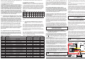
Diese Anleitung gilt für folgende Decodertypen:
The decoder does not operate with Marklin digital (Motorola format). This instruction is for the following decoders:
Art.- Lichtausgänge
Nr.
5240
2
5241
2
16
Table of Contents
1. Einleitung . . . . . . . . . . . . . . . . . . . Introduction . . . . . . . . . . . . . . . . . 1
Schnittstellen- Abmessungen
Stecker
in mm (ca.)
9,3 x 12,0 x 3,4
NEM 651 "S"
9,3 x 14,0 x 3,4
Item Function outputs
No. Including lights
5240
2
5241
2
Interfaceplug
NEM 651 "S"
Dimensions
in mm (ca.)
9.3 x 12.0 x 3.4
9.3 x 14.0 x 3.4
Technische Daten und Merkmale:
kurze und erweiterte (4-stellige) Adressen sowie 14, 28 und
128 Fahrstufen
einstellbare Mindest-, Mitten- und Höchstgeschwindigkeit
Programmierung während der Fahrt möglich
Lichtausgänge mit programmierbaren Lichteffekten
maximale Fahrspannung (Eingangsspannung)
24 V
maximaler Motorstrom
0,5 A
maximaler Strom pro Lichtausgang
200 mA
Gesamtbelastbarkeit (Analog- / Digitalbetrieb)
0,5 A / 0,6 A
Betriebstemperatur
0 bis 60 °C
Technical Data and Features:
short and extended (4-digit) addresses and 14, 28 and 128
speed steps
adjustable low-, medium- and maximum speed
programming on the mains
light outputs with programmable light effects
maximum operating voltage (track voltage)
24 V
maximum motor current
0.5 A
maximum current per light output
200 mA
total load (analogue / digital operation)
0.5 A / 0.6 A
operating temperature
0 bis 60 °C
Der Decoder besitzt Schutzvorrichtungen gegen Überströme an
den Motor- und Lichtausgängen. Damit sind jedoch Beschädigungen z.B. durch Kurzschlüsse zwischen Stromaufnehmer
und Motor, Kurzschluss zwischen Motorausgang und Lokfahrgestell und Überlastung des Decoders nicht ausgeschlossen.
The motor and light outputs of the decoder are protected
against excess current. However, damage may be caused by
short circuit between current pick-up and motor, short circuit
between motor output and locomotive chassis or overloading
the decoder.
1
2. Wichtige Hinweise
2. Important Information
Lesen Sie vor der ersten Benutzung des Produktes bzw. dessen Einbau diese Bedienungsanleitung aufmerksam durch.
Read the operating instructions carefully before using the
product for the first time or assembling it.
2.1. Das Produkt richtig verwenden
2.1. Using the product correctly
Dieser Lokomotivdecoder ist bestimmt
This locomotive decoder is intended
zum Einbau in Modelleisenbahnen
for installation in model railroads.
zum Betrieb an einem zugelassenen Modellbahntransformator bzw. an einer damit versorgten digitalen Modellbahnsteuerung
for connection to an authorized model railroad ransformer or
an digital model railroad control system connected to one
zum Betrieb in trockenen Räumen
Jeder darüber hinausgehende Gebrauch gilt als nicht bestimmungsgemäß. Für hieraus resultierende Schäden haftet der
Hersteller nicht; das Risiko hierfür trägt allein der Benutzer.
for operation in a dry area
Using the product for any other purpose is not approved and is
considered incorrect. The manufacturer cannot be held responsible for any damage resulting from the improper use of this
product; liability in such a case rests with the user.
Der Decoder darf nur in Modellbahnen eingesetzt werden!
The decoder is only allowed to be put in model railways!
Achtung: Ein Betrieb des Decoders auf analogen Wechselstromanlagen mit Umschaltimpuls ist nicht zulässig! Die
hohe Spannung des Umschaltimpulses führt zur Zerstörung des Decoders.
Please note: This decoder is not suitable for operation
with conventional AC supply and the voltage pulse for
change of direction! The high voltage of this pulse will
cause the destruction of the decoder.
Decoders ein Herstell- oder Materialfehler festgestellt, wird der
Decoder kostenlos instand gesetzt.
Von der Garantie ausgeschlossen sind Beschädigungen des
Decoders, die durch unsachgemäße Behandlung, Nichtbeachten der Bedienungsanleitung, nicht bestimmungsgemäßen Gebrauch, Überlastung, fehlerhafte Verdrahtung (z.B. durch Kurzschlüsse zwischen Stromaufnehmer und Motor, Kurzschluss
zwischen Motorausgang und Lokfahrgestell), eigenmächtigen
Eingriff, bauliche Veränderungen, Gewalteinwirkung, Überhitzung u.ä. verursacht werden.
Jede Haftung für Schäden und Folgeschäden durch nicht bestimmungsgemäßen Gebrauch, Nichtbeachtung der Bedienungsanleitung, eigenmächtigen Eingriff, bauliche Veränderungen, Gewalteinwirkung, Überhitzung, Überlastung, Feuchtigkeitseinwirkung u.ä. ist ausgeschlossen.
failure occur during this period please contact your dealer or
Viessmann directly. Should the inspection of the decoder indicate faulty material or workmanship then we will replace this decoder free of charge.
Our warranty becomes null and void in case of damage caused
by inappropriate use of the product, disregard of the instruction
manual, abnormal operating conditions, overload, faulty wiring
(e.g. through short circuits between current pick up and motor,
short circuits between motor output and chassis), unauthorized
modifications, overheating etc..
Viessmann may not be held responsible for any damage or
consequential loss or damage caused by inappropriate use of
the product, disregard of the instruction manual, unauthorized
modifications, abnormal operating conditions, overheating,
overload, exposure to humidity, etc..
Technische Änderungen vorbehalten!
3. Einbau des Decoders
3. Installing the Decoder
3.1. Vorbereitung
3.1. Preparation
Es können nur Lokomotiven mit einem Digitaldecoder ausgerüstet werden, die im Gleichstrombetrieb einwandfrei funktionieren. Besonders im Digitalbetrieb ist eine sichere und unterbrechungsfreie Stromaufnahme wichtig. Ersetzen Sie verschlissene Kohlebürsten und defekte Lämpchen und reinigen Sie die
Radschleifer. Der Decoder sollte an einer Stelle in der Lok eingebaut werden, wo mit der geringsten Wärmeentwicklung zu
rechnen ist.
Only locomotives, which run smoothly in analogue mode,
should be equipped with a digital decoder. A secure and uninterrupted current pickup is important especially in digital mode.
Change worn coal brushes and defect lights and clean wheel
pick-ups. The decoder should be installed inside the locomotive
in such a way as to avoid overheating.
Werkzeug: Verwenden Sie für den Decodereinbau einen Lötkolben mit max. 30 Watt Leistung (wenn vorhanden mit Temperaturregelung), Elektroniklötzinn (kein Lötfett) sowie Seitenschneider (zum Kürzen der Anschlussdrähte) und kleine
Schraubendreher. Zusätzlich benötigen Sie Isolierband (um Metallteile der Lok abzukleben) und doppelseitige Klebepads (z.B.
aus dem Lokdecoder-Einbauset 6819 von Viessmann) zum Befestigen des Decoders.
Vor dem Einbau des Decoders ist der Motor vollständig zu
isolieren, d.h. es dürfen keine elektrischen Verbindungen zwischen Motoranschlüssen und Radschleifer existieren. Merken
Sie sich, welcher Motoranschluss mit dem rechten bzw. linken
Radschleifer verbunden war.
Hinweis zu älteren Loks der Firma Fleischmann: Häufig ist
bei diesen Loks der Motorschild ein Teil der Motorstromversorgung und mit einem der Radschleifer verbunden. Um den Motor
zu isolieren, müssen Sie diese Verbindung auftrennen oder einen neuen Lagerschild einsetzen.
3.2. Strombelastbarkeit
Neben den gewünschten Funktionen und dem verfügbaren Einbauraum ist die Stromaufnahme des Lokmotors unter Volllast
wesentlich bei der Auswahl des richtigen Decoders.
Der Decoder 5240/5241 kann einen Motorstrom von 0,5 A liefern. Angaben über die Stromaufnahme der Lok beziehen sich
in der Regel auf eine Spannung von 12 oder 14 Volt. Liegt die
Digitalspannung Ihrer Digitalzentrale höher (z.B. Roco "Lokmaus I / II", Lenz "compact", LGB, Intellibox, Twin-Center),
steigt die Stromaufnahme an und kann so eventuell den Wert
von 0,5 A überschreiten. Für den Betrieb von Fahrzeugen der
Spurweite N wird eine Digitalspannung von ca. 14 Volt empfohlen.
Die Gesamtstrombelastbarkeit des Decoders 5240/5241 beträgt
im Digitalbetrieb 0,6 A. Benötigt der Motor z.B. 0,5 A, stehen für
die Lichtausgänge insgesamt nur noch 100 mA zur Verfügung.
2
Subject to technical change!
Für eigene Notizen:
For your own notes:
Tools: For installing the decoder please use a soldering iron
with 30 Watts max. (if possible with temperature control), electronic solder (no soldering paste) and side cutters (to shorten
the leads) and small screw drivers. You also need insulation
tape (to cover any metal parts of the locomotive) and double
sided tape (such as included in Viessmann locomotive decoder
installation set 6819) to fasten the decoder.
Before installing the decoder you have to completely insulate
the motor, which means there should not be any electrical connection between motor and wheel pick-ups. Don't forget which
motor terminals were connected with the right or left wheel pickup.
Advice for older Fleischmann locomotives: Often in these locomotives the motor shield is part of the motor's power supply
and therefore connected with one of the wheel pick-ups. To insulate the motor you have to cut off this connection or replace
the motor shield.
3.2. Maximum Current Load Capacity
Besides the desired functions and the available installation
space the current draw of the motor under full load determines
the selection of a suitable decoder.
The decoder 5240/5241 supplies a motor current of 0.5 A. Values regarding current draw of the locomotives generally refer to
a voltage of 12 or 14 V. Is the digital voltage of your command
station higher (e.g. Roco "Lokmaus" I / II, Lenz "compact", LGB,
Intellibox, Twin-Center), the current draw rises and could potentially exceed the permitted value of 0.5 A. For operating N
gauge a track voltage of approx. 14 V is recommended.
The total current load capacity of the decoder 5240/5241 in digital mode is 0.6 A. If the motor draws e.g. 0.5 A, then the total
current available for all the light outputs is 100 mA.
Each light output of the decoder 5240/5241 can supply 200 mA.
Please observe the maximum load capacity of the decoder and
each individual output. The decoder may be destroyed through
overload!
15
meldet die Zentrale einen Fehler. Das Programmieren des zweiten Adressteils wird deshalb nicht ausgeführt!
7.5.2.
Verwendungshinweise
Um das Problem der mehrstufigen Programmierverfahren zu
umgehen, müssen Sie die beiden Adressteile manuell in CV#
17 und CV# 18 programmieren und anschließend in CV# 29
den erweiterten Adressmodus einstellen.
Soll z.B. die Adresse 2.110 eingestellt werden, müssen zuerst
die beiden Adressteile ermittelt werden. Zuerst ist 2.110 durch
256 zu teilen und der gerade Anteil plus 192 in CV# 17 einzutragen, hier also 200 (= 192 + 8). Der Divisionsrest (2.110 - 8 *
256 = 62) ist in CV# 18 zu programmieren. Die Nutzung der erweiterten Adressen wird durch Eintragen des Wertes von 32
(bei 14 Fahrstufen) bzw. 34 (bei 28 Fahrstufen) eingestellt.
Eine weitere Möglichkeit ist der Anschluss einer Last am Motorausgang (z.B. Widerstand von 100 Ohm oder Glühlämpchen).
Somit erfolgt wieder eine korrekte Rückmeldung und die Programmierung arbeitet fehlerfrei. Damit diese Last aber im normalen Betrieb nicht angesteuert wird, muss durch Einstellung
der Konfigurationsregister der Ausgang abgeschaltet werden.
Programmieren Sie in CV# 2 den Wert 1, in CV# 5 und CV# 6
jeweils den Wert von 2. Löschen Sie sicherheitshalber auch alle
Positionen der Geschwindigkeitstabelle (CV# 67 bis CV# 94).
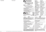
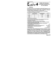
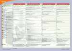
8. Umrechnungstabelle
Soll die Geschwindigkeitskennlinie genau an Ihre Lokomotive
angepasst werden, ist dabei die Umrechnungstabelle (Tabelle
8) hilfreich. An einem Beispiel soll ihre Nutzung erklärt werden:
Angenommen, Ihre Lokomotive fährt bei der höchsten Fahrstufe zu schnell. Aus diesem Grund soll die Höchstgeschwindigkeit
z.B. auf 80 % begrenzt werden (durch Begrenzung der Motorspannung auf 80 %). In das Konfigurationsregister "Maximalspannung" (CV# 5) ist ein Wert von 80 % einzutragen. In vielen
DCC-Zentralen müssen Sie den Wert von 80 % vorher in eine
für die Zentrale verständliche Form "übersetzen".
In der nachfolgenden Umrechnungstabelle finden Sie für 80 %
Motorspannung den dezimalen Wert "204". In der Tabelle ist nur
jeder 4. Wert eingetragen, Zwischenwerte können durch mitteln
einfach bestimmt werden.
ming methods, e.g. when programming an extended address
(4-digit address) with the Intellibox or the Twin-Center. The 4digit address has to be divided into two values that have to be
entered individually. Since there is no feedback after entering
the first two digits, the command station will display an error
message and because of that the second part of the address
cannot be programmed.
7.5.2.
Application Advise
To avoid the multi-tiered programming method you have to
enter both parts of the extended address separately into CV#
17 and CV# 18. You also have to activate the extended address
mode in CV# 29.
Let's assume you want to set the address 2110. first you have
to establish the two parts of this address. Divide 2110 by 256,
round the result and add 192, then enter this value into CV# 17
in this example: 200 (= 192 + 8). The remaining amount of this
calculation (2110 - 8 * 256 = 62) has to be entered into CV# 18.
To activate the extended address enter the value 32 (when
operating with 14 speed steps) respectively 34 (when operating
with 28 speed steps) into CV# 29.
Another option is to connect a load to the motor output (e.g. a
100 Ohm resistor or an incandescent lamp). This allows the
correct feedback to the command station and programming
works without fail. To avoid that this load is actually powered
during normal operation you have to switch off this output by
programming several CVs. Enter the value 1 in CV# 2, and 2 in
CV# 5 and CV# 6. To play it save delete all values in the speed
table (CV# 67 to CV# 94).
8. Conversion Table
If you want to adapt the speed curve precisely to your locomotive, the conversion table (table 8) will be helpful. The following
example explains how to use it:
Let's assume your locomotive drives too fast at the highest
speed step, and you want to reduce the maximum speed e.g. to
80 % (through reducing the motor voltage to 80 %). Enter a
value of 80 % into the configuration register maximum speed
(CV# 5). To be able to program the DCC command station the
value must be "translated”.
Besonders leicht ist die Programmierung der Geschwindigkeitskennlinie mit der PC-Software WINiPRO (Viessmann-Art.-Nr.
1021). Dort erfolgt in Verbindung mit der Intellibox, dem TwinCenter oder dem Interface von Lenz die Einstellung grafisch per
ziehen mit der Maus.
In the table 8 you find a numerical value of 204 for 80 % motor
voltage. The table contains only every fourth value; all other values can be interpolated.
Tabelle 8
Umrechnung zwischen Motorspannung in Prozent und dezimalen Eingabewerten bei der Programmierung
Wert
%
Wert
%
Wert
%
Wert
%
Value
%
Value
%
Value
%
Value
%
0
0,0
32
12,5
64
25,1
96
37,6
4
1,6
36
14,1
68
26,7
100
39,2
8
3,1
40
15,7
72
28,2
104
40,8
12
4,7
44
17,3
76
29,8
108
42,4
16
6,3
48
18,8
80
31,4
112
43,9
20
7,8
52
20,4
84
32,9
116
45,5
24
9,4
56
22,0
88
34,5
120
47,1
28
11,0
60
23,5
92
36,1
124
48,6
Table 8
Conversion between motor voltage in percent and numerical
programming value
Wert
%
Wert
%
Wert
%
Wert
%
Value
%
Value
%
Value
%
Value
%
128
50,2
160
62,7
192
75,3
224
87,8
132
51,8
164
64,3
196
76,9
228
89,4
136
53,3
168
65,9
200
78,4
232
91,0
140
54,9
172
67,5
204
80,0
236
92,5
144
56,5
176
69,0
208
81,6
240
94,1
148
58,0
180
70,6
212
83,1
244
95,7
152
59,6
184
72,2
216
84,7
248
97,3
156
61,2
188
73,7
220
86,3
252
98,8
9. Garantie
with the Intellibox, the Twin-Center or the interface from Lenz
you are able to define the speed curve graphically by drawing it
with the mouse.
Jeder Decoder wird vor seiner Auslieferung auf vollständige
Funktion überprüft.
Der Garantiezeitraum beträgt 2 Jahre ab Kaufdatum des Decoders. Tritt in dieser Zeit ein Fehler auf, setzen Sie sich bitte direkt mit Viessmann in Verbindung. Wird nach Überprüfung des
14
Very easy is the programming of the speed curve by using the
PC-Software WINiPRO (Viessmann article # 1021). Combined
9. Warranty
Every decoder is fully tested before delivery.
The warranty period is 2 years from date of purchase. Should a
Jeder Lichtausgang des Decoders 5240/5241 kann maximal
200 mA treiben.
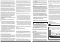
3.3. Installing the Decoder 5241 in Locomotives with Interface as per NEM 651 "S"
Beachten Sie die maximale Belastbarkeit des Decoders und
seiner einzelnen Ausgänge. Bei Überlastung kann der Decoder
zerstört werden!
Once you have opened the locomotive remove the bridge plate
from the interface socket on the circuit board and insert the plug
of the decoder instead. Please make sure that the pin 1 of the
decoder (see figure 1) and the Pin1-mark of the circuit board
(often a "*" or "+") match.
3.3. Einbau des Decoders 5241 in Loks mit NEM 651 "S"Schnittstellenbuchse
Nach dem Öffnen der Lok entfernen Sie den Brückenstecker
aus der Schnittstellenbuchse auf der Schaltplatine der Lok. An
die Stelle des Brückensteckers stecken Sie den Schnittstellenstecker des Decoders ein. Dabei müssen die Pin1-Markierungen von Decoder (siehe Abbildung 1) und Lokleiterplatte (häufig
ein "*" oder "+") übereinstimmen.
Kleben Sie in der Nähe befindliche Metallteile mit Isolierband
ab.
Wickeln Sie den Decoder nicht in Isolierband ein, da hierdurch
die Wärmeabfuhr behindert wird. Der Decoder kann so thermisch überlastet werden.
Die Bauteile des Decoders dürfen auf keinen Fall Metallteile des Lokfahrgestells oder Gehäuses berühren.
Dadurch verursachte Kurzschlüsse führen zur Zerstörung
des Decoders.
Abbildung 1
Figure 1
Decoder
5241
Schnittstellenbuchse auf Lokleiterplatte
Interface socket on locomotive circuit
board
Insulate all metal parts close to the decoder but don't wrap the
decoder with insulation tape to avoid overheating. Otherwise
the decoder may be thermally overloaded.
Under no circumstances should components of the
decoder touch any metal parts of the chassis or the
locomotive body. Resulting short circuits will destroy the
decoder.
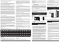
Markierung marking
Abbildung 2
Figure 2
*
Markierung marking
orange
gelb
1
orange orange
2
grau
gray
*
orange
1
5
rot
red
3
rot
yellow
2
6
(blau blue)
4
schwarz black
3
7
weiß white
5
weiß
white
grau gray
6
gelb
yellow
schwarz black
4
8
NEM 652
red
NEM 651 "S"
Schnittstellenbuchsen
Interface Sockets
Decoder
5241
1
Pin 1 pin 1
Markierung
marking
*
3.4. Einbau des Decoders 5240 (ohne Schnittstellenstecker)
Vor dem Einbau sind der Motor und die Motoranschlüsse komplett gegen das Fahrwerk der Lok und die Stromaufnehmer
(Radschleifer) zu isolieren. Merken Sie sich, welcher Motoranschluss mit dem rechten bzw. linken Radschleifer verbunden
war.
1) Vor Beginn der Arbeiten sollten Sie sich an einer Heizung
bzw. Wasserrohr entladen, um den Decoder vor Beschädigung durch elektrostatische Entladung zu schützen. Tragen
Sie beim Decodereinbau Kleidung aus Baumwolle!
2) Ist in Ihrer Lok eine NEM-Schnittstelle vorhanden, ist der Decodereinbau sehr einfach. Entfernen Sie zuerst den in der
Schnittstelle befindlichen Brückenstecker. Wenn Sie nun auf
die Schnittstellenbuchse in der Lok schauen, werden Sie an
einer Seite eine Markierung finden - diese kennzeichnet Anschluss 1. Löten die Anschlusskabel des Decoders entsprechend Abbildung 2 auf bzw. neben die jeweiligen Anschlüsse der Buchse oder stecken die verzinnten Enden in die
Schnittstellenbuchse. Bezüglich des blauen Kabels bei der
NEM 652-Buchse lesen Sie bitte Punkt 5. Die folgenden
Punkte 3 und 4 können Sie überspringen, diese gelten nur
für Lokomotiven ohne Schnittstellenbuchse.
3) Besitzt die Lok keine Schnittstellenbuchse, verbinden Sie
den roten Anschlussdraht des Decoders mit dem rechten
Radschleifer, den schwarzen Anschlussdraht des Decoders
mit dem linken Radschleifer der Lok.
4) Löten Sie den orangen Anschlussdraht an den Motoranschluss, der vor Einbau des Decoders mit dem rechten Radschleifer verbunden war. Löten Sie den grauen Anschlussdraht an den Motoranschluss, der vorher mit dem linken
Radschleifer verbunden war. Die Entstörelemente, die vor
3.4. Installing the Decoder 5240 (without interface-plug)
Before you start, completely insulate the motor and its terminals against the chassis of the locomotive and the current pickups (wheel pick-ups). Remember which motor terminal was
connected with the right or left wheel pick-up.
1) Before you start, you have to discharge any electrostatic
charge by touching a water tap (or radiator) to avoid damage
through an electrostatic discharge. Clothes made of cotton
are best suited for working with decoders.
2) If there is a NEM interface in your locomotive, the installation
of the decoder is very easy. At first remove the bridge plate
from the interface socket. If you look now on the top of the
interface socket in the loco, you will see a marking on one
side - this is pin 1. Solder the wires according to figure 2 onto
or next to the individual contacts of the NEM socket or insert
the soldered wire ends into the socket. For the blue wire of
NEM 652 socket please refer paragraph 5. Disregard following paragraphs 3 to 4. They are only valid for locomotives
without interface.
3) If the locomotive has no NEM interface socket, connect the
red wire from the decoder to the right wheel pick-up, the
black wire from the decoder to the left wheel pick-up of the
locomotive.
4) Solder the orange wire to the motor terminal, which was connected to the right wheel pick-up before installation. Solder
the grey wire to the motor terminal, which was connected to
the left wheel pick-up. The RFI suppression components,
which were connected to the motor before installation, should
remain in the circuit in front of the motor. Otherwise disturbances, generated by the motor, could impair the functionality of the decoder.
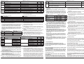
5) The decoder 5240 has no positive supply for the light outputs
(blue wire of H0 decoders). Instead, the lights are connected
with the wheel pick-ups according to either of the following
three methods:
3
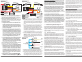
Abbildung 3a
Figure 3a Licht vorne
Abbildung 3b
Figure 3b
Licht hinten
back light
front light
weiß
white
gelb
yellow
Licht vorne
front light
Licht vorne
back light
weiß
white
grau
grey
gelb
yellow
grau
grey
M
Decoder 5240
Decoder 5240
rot
red
schwarz
black
orange
orange
Achtung: Motor
vollständig isolieren!
M
Decoder 5240
Decoder 5240
rot
red
schwarz
black
5) Der Decoder 5240 besitzt keine positive Versorgung für die
Lichtausgänge (blauer Draht bei H0-Decodern). Die Lampen
werden statt dessen mit den Radschleifern nach folgenden
drei Varianten verbunden:
Sind die Lampenfassungen der Lokomotive gegen das
Fahrgestell isoliert, verwenden Sie am Besten den in Abbildung 3a gezeigten Anschluss. Die Lampe für Licht vorne wird über den weißen Draht mit dem Decoder 5240
verbunden. Der andere Pol wird mit dem roten Radschleiferdraht verbunden (Licht hinten an schwarzen Radschleiferdraht). Bei dieser Anschlussart funktionieren die Lampen auch im Analogbetrieb.
In Lokomotiven, bei denen der eine Pol der Lampenfassungen mit dem Fahrgestell elektrisch verbunden ist, verwenden Sie den in Abbildung 3b gezeigten Anschluss der
Lichtausgänge. Bitte beachten Sie bei dieser Anschlussart, dass im Analogbetrieb je nach Polarität der Gleisspannung die Lichtausgänge nicht arbeiten. Der Kurzschlussschutz ist nur eingeschränkt wirksam. Verwenden Sie diese Anschlussart in Verbindung mit Zentralen, die neben
dem DCC-Signal auch Signale im Motorola-Format senden, können Helligkeitsschwankungen auftreten.
Um Zusatzeinrichtungen (Licht, Dampfgeneratoren usw.)
an einem Lichtausgang mit voller Leistung anzuschließen,
muss eine positive Versorgung für die Lichtausgänge
(= blauer Draht bei H0-Decodern) mittels zweier Dioden
(Viessmann Art.-Nr. 6834, 10 Stück) entsprechend Abbildung 4 erzeugt werden. Dieser Anschluss wird im Folgenden als "blauer" Anschlussdraht bezeichnet.
Für die Lichtausgänge A (weiß) und B (gelb) gibt es zwei Betriebsarten. Die Einstellung erfolgt mittels CV# 56:
Bei Benutzung der Ausgänge für fahrtrichtungsabhängige Beleuchtung wird der weiße Anschlussdraht mit dem in
Fahrtrichtung vorderen und der gelbe Anschlussdraht mit
dem hinteren Lämpchen verbunden. Die noch freien Pole
der Lämpchen schließen Sie entweder gemäß Abbildung
3a, 3b oder am "blauen" Anschlussdraht (siehe Text oben
und Abbildung 4) an. Bei der Verwendung von LEDs verbinden Sie die Anoden mit dem Schleifer bzw. dem "blauen" Anschlussdraht und die Kathoden über einen Vorwiderstand von ca. 1 kOhm / 0,125 W mit dem gelben bzw.
weißen Anschlussdraht.
Bei Benutzung der Ausgänge für fahrtrichtungsunabhängiges Licht und eine Zusatzfunktion wird der weiße
Anschlussdraht mit der Beleuchtung und der gelbe Draht
4
orange
orange
Entweder rot oder
schwarz ist mit dem
Lokfahrgestell verbunden.
Red or black wire is
connected to the
locomotive chassis.
Caution: Insulate the
motor completely!
Einbau des Decoders mit dem Motor Ihrer Lokomotive verbunden waren, sollten in der Motorzuleitung verbleiben. Die
vom Motor erzeugten Störimpulse könnten sonst die fehlerfreie Funktion des Decoders beeinträchtigen.
Hinweis zum Programmiergleis: Beim Einbau von Decodern
sollten diese zuerst auf einem Gleis mit Strombegrenzung getestet werden. Schalten Sie die Intellibox bzw. Twin-Center zuerst in den Programmiermodus. Sie hören im Gerät ein Relais
klicken. Erst dann können Sie ohne Gefahr für den Decoder die
Lok auf das Programmiergleis stellen und den Decoder auslesen.
Achtung: Motor
vollständig isolieren!
Caution: Insulate the
motor completely!
If the light sockets of the locomotive are insulated against
the chassis (potential-free), wire them as shown in figure
3a. The bulb for the forward light is to be connected to the
white wire. The other pole is to be connected with the red
wheel pick-up (reverse light to black wheel pick-up wire).
Wired in this manner the lights will also work in analogue
mode.
In locomotives, where one pole of the light socket is electrically connected with the chassis, wire the outputs as
shown in figure 3b. Please note, that with this wiring methode the light outputs don't work in analogue mode depending on the polarity of the track voltage. Also, short circuit protection only works partially. This wiring method
may result in variations of brightness if used with command stations, which transmit signals in Marklin-Motorola
format besides the DCC-signals.
In order to operate auxiliary devices (e.g. lights, steam generator) at full output, a positive supply of the light outputs has to be generated by means of two diodes (Viessmann article # 6834, 10 pieces per pack) as shown in figure 4 (this serves the same purpose as the "blue" wire in
H0-decoders). In the following paragraphs we will call this
connection point the "blue" wire.
Abbildung 4
Figure 4
Licht hinten
back light
Licht vorne
front light
"blauer"
Anschlussdraht
"blue" wire Kathode
gelb
yellow
weiß
white
Anode
rot
red
2x Diode 6834
Kathode
Anode
schwarz
black
Light outputs A (white) and B (yellow) may be operated in
two different ways. The adjustment is done with CV# 56:
When using the outputs for directional headlights connect
the white wire with the forward bulb (in direction of travel)
and the yellow wire with the rear bulb. Connect the other
poles of the bulbs either like shown in figure 3a, 3b or connect them with the "blue" wire (please see the paragraph
above and figure 4). When using LEDs, connect the
Werden mit der Intellibox "lange" Adressen gelesen oder programmiert, so setzt die Intellibox den Decoder automatisch auf
die Nutzung der erweiterten Adresse (CV# 29, Bit 5 = 1). Der
Decoder fährt demzufolge nicht mehr unter seiner kurzen
Adresse. Sie müssen die Nutzung der kurzen Adresse durch
das Löschen von Bit 5 in CV# 29 wieder aktivieren. Programmieren Sie einfach die kurze Adresse, das Löschen von CV# 29
/ Bit 5 erfolgt durch den Decoder automatisch.
7.4. Anschluss von Glockenankermotoren
Glockenankermotoren besitzen ein sehr geringes Trägheitsmoment und fahren schon bei sehr kleinen Motorspannungen an.
Unter Beachtung des maximalen Motorstroms lassen sich auch
Glockenankermotoren mit dem Decoder 5240/5241 ohne Gefahr für Motor und Decoder verwenden. Gegenüber einer hochfrequenten Ansteuerung (~ 16 kHz) wird beim 5240/5241 der
Motor mit einer Frequenz von ca. 120 Hz angesteuert. Dadurch
ist unter Umständen im unteren Drehzahlbereich mit einer leichten Geräuschentwicklung zu rechnen. Diese hängt aber im wesentlichen von der mechanischen Konstruktion der Lok ab und
kann deshalb nur durch Versuche bestimmt werden.
7.5. Hinweise zur Verwendung des Decoders 5240 zur
Lichtumschaltung, z.B. im Steuerwagen
Für die Steuerung von Zusatzfunktionen stehen beim Decoder
5240 zwei Lichtausgänge zur Verfügung. Sollen weitere Funktionen in der Lok oder Lichtfunktionen in einem Steuerwagen
geschaltet werden, wird normalerweise ein Funktionsdecoder
eingesetzt. Es besteht jedoch auch die Möglichkeit, einen normalen Lokdecoder z.B. für die Lichtsteuerung in einem Steuerwagen zu verwenden.
7.5.1.
Technischer Hintergrund
Lokdecoder und Funktionsdecoder sind sich in ihrem Aufbau
sehr ähnlich. Die Decoder unterscheiden sich nur in der Konstruktion der Ausgangstreiberstufen. So lassen sich z.B. auch
Lokdecoder zum Schalten von Zusatzfunktionen z.B. in einem
Steuerwagen verwenden. Allerdings sind bei der Programmierung folgende Besonderheiten zu beachten:
Beim Programmiervorgang schreibt die Zentrale einen Wert
zum Decoder. Der Decoder schreibt den Wert in den internen
Speicher, damit die Werte auch nach einer Spannungsunterbrechung erhalten bleiben. Ist dieser Vorgang erfolgreich,
schalten Lokdecoder den Motorausgang ein. Der dadurch verursachte Stromfluss durch den Motor zeigt der Zentrale, dass
der Programmiervorgang erfolgreich abgeschlossen ist. Ist nun
kein Motor angeschlossen, erfolgt kein Stromfluss und damit eine Fehlermeldung. Ein Auslesen von CV-Werten ist demzufolge
ebenfalls nicht möglich.
Grundsätzlich gilt: Für die korrekte Rückmeldung beim Programmieren des Decoders ist eine Last am Motorausgang nötig!
Prinzipiell lassen sich so trotzdem alle Konfigurationsvariablen
(CVs) programmieren. Sie erhalten jedoch immer eine Fehlermeldung und können die CVs nicht auslesen.
Probleme entstehen jedoch bei mehrstufigen Programmierverfahren, z.B. bei der Intellibox oder beim Twin-Center das Programmieren einer langen Adresse. Die vierstellige Adresse wird
in zwei Werte aufgeteilt und einzeln programmiert. Da nach der
Programmierung des ersten Wertes keine Rückmeldung erfolgt,
uncontrolled after switching on the Intellibox, because DCC
decoders interpret the Motorola signal as an analogue signal.
Set to "N” gauge to limit the track voltage to 18 V. This is kind to
the motors of your locomotives.
When operating decoders with Motorola- or Selectrix-format at
the same time as DCC decoders, the Intellibox transmits the
different signal formats alternately. Therefore the number of
signal transmissions for DCC decoders is reduced. In case of
dirty track and the resulting intermittent contact, locomotives
with DCC decoders may not run smoothly.
Advice to the programming track: The first test after the builtin of a decoder should be performed on a track with a current
limiter. First switch the Intellibox or the Twin-Center to the programming mode! You will hear the click of a relay inside the
command station. Only after that you can put the locomotive
onto the programming track without risk for the decoder and
read it out.
The Intellibox recognizes long addresses and automatically
switches to extended address mode (CV# 29, Bit 5 = 1). Therefore the decoder does not operate with its short address. To activate the short address, delete Bit 5 in CV# 29. Just program
the short address and the decoder will delete CV# 29 / bit 5
automatically.
7.4. Connecting Coreless Motors
Coreless motors have very little momentum and start turning at
a very low motor voltage.
Coreless motors can be operated with decoder 5240/5241
without risk for motor and decoder, provided you observe the
maximum motor current. Contrary to high frequency-motor-control (~16 kHz), the decoder 5240/5241 use a tact frequency of
about 120 Hz. There may be some noise at low revs. Noise generation depends greatly on the construction of the locomotive
and can only be determined by testing.
7.5. Hints for Using the Decoder 5240 to switch directional
Lights e.g. in a Driving Trailer
To control auxiliary functions the decoder 5240 has two light
outputs. Normally you would use a function decoder to control
additional functions in the locomotive or head lights and rear
lights in the driving trailer. However, you can also use a mobile
decoder e.g. for controlling the lights in a driving trailer.
7.5.1.
Technical Background
The construction of mobile decoders and function decoders is
very similar. The only difference is in the design of the output
circuitry. Thus it is possible to use a mobile decoder for
switching auxiliary functions e.g. in a driving trailer. You just
have to take into account the following factors when programming a decoder:
During programming the command station writes a value into
the memory of the decoder. Thus the values will be stored even
after an interruption of the track voltage. If this procedure is
carried out successfully the decoder turns on the motor output.
The current that is now flowing through the motor indicates to
the command station that the programming has been completed
successfully. If there is no motor in the circuit, there is no
current, which in turn results in an error display. Therefore it is
not possible to read out any CVs.
The basic rule is: To assure the correct feedback from the
decoder to the command station a load has to be connected to
the motor output!
Nevertheless you can program any CV as desired. However,
you will always get an error display and you will not be able to
read out any CV values.
This becomes more difficult when using multi-tiered program-
13
lichkeiten:
Die Stirnlampen des Triebwagens werden richtungsabhängig
gesteuert, d.h. in Vorwärtsrichtung leuchten die Lämpchen
vorne und in Rückwärtsrichtung leuchten die Lämpchen hinten, wenn die Funktion F0 eingeschaltet ist. Die Innenbeleuchtung ist ebenfalls eingeschaltet, wenn die Funktion F0
eingeschaltet ist.
Die Stirnlampen des Triebwagens werden richtungsunabhängig gesteuert, d.h. in Vorwärtsrichtung und in Rückwärtsrichtung leuchten die Lämpchen hinten und vorne gleichzeitig, wenn die Funktion F0 eingeschaltet ist. Die Innenbeleuchtung kann separat durch die in CV# 58 festgelegte
Funktion (z.B. F1) ein- bzw. ausgeschaltet werden.
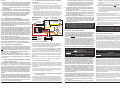
7.2.1.
Stirnlampen richtungsabhängig
Die Lichtausgänge werden auf richtungsabhängigen Betrieb
programmiert. Diese Einstellung entspricht dem Auslieferungszustand des Decoders 5240/5241. Die Einstellung wird im UserKonfigurationsregister 1 (CV# 56) vorgenommen. Dazu ist in
diesem Register das Bit 0 zu löschen (entspricht einem Zahlenwert von 0, siehe Abschnitt 5.4.).
Damit die Innenbeleuchtung eingeschaltet wird, wenn entweder
das vordere Lämpchen oder das hintere Lämpchen leuchtet,
sind zwei zusätzliche Dioden (z.B. Viessmann Art.-Nr. 6834, 10
Stück) erforderlich. Die Kathoden der Dioden (Kennzeichnung
an der Diode durch einen Farbring) werden an den gelben bzw.
weißen Anschlussdraht gelötet. Die Anoden werden zusammen
an den einen Pol der Innenbeleuchtung angeschlossen. Der andere Pol der Innenbeleuchtung wird mit dem Radschleiferanschluss verbunden (siehe Abbildung 6).
Die Lichtausgänge sind in der gewohnten Weise richtungsabhängig, d.h. in Vorwärtsrichtung leuchten die Lämpchen vorn
und in Rückwärtsrichtung leuchten die Lämpchen hinten, wenn
die Funktion F0 eingeschaltet ist. Die Innenbeleuchtung ist
ebenfalls eingeschaltet, wenn die Funktion F0 eingeschaltet ist.
7.2.2.
Stirnlampen richtungsunabhängig
Soll die Innenbeleuchtung unabhängig von den Stirnlämpchen
eingeschaltet werden, müssen die Lichtausgänge auf richtungsunabhängigen Betrieb programmiert werden. Die Einstellung
wird im User-Konfigurationsregister 1 (CV# 56) vorgenommen.
Dazu ist in diesem Register Bit 0 zu setzen(entspricht einem
Zahlenwert von 1, siehe Abschnitt 5.4.).
Die Verschaltung der Innenbeleuchtung entspricht dem Anschluss einer Zusatzfunktion (siehe Abschnitt 7.1., Abbildung 5).
In der Schaltung ist der Dampfgenerator durch eine Glühlampe
zu ersetzen.
7.3. Verwendung des Decoders 5240/5241 mit der Intellibox oder dem Twin-Center
Die Intellibox ist im Grundzustand auf das Märklin-Motorola-Format eingestellt. Sollen DCC-Decoder verwendet werden, ist diese Grundeinstellung entsprechend dem Handbuch der Intellibox
zu ändern (Sonderoption 25 = 1, Sonderoption 907 = 4 oder 5).
Falls diese Umstellung nicht erfolgt, fahren DCC-Decoder eventuell beim Einschalten der Intellibox unkontrolliert los, da die
DCC-Decoder das Motorola-Format als Analogsignal interpretieren. Stellen Sie die Spurweite "N" ein, damit die Gleisspannung max. 18 V beträgt und die Motoren Ihrer Loks geschont
werden.
Werden neben DCC-Decodern auch gleichzeitig Decoder mit
Motorola- bzw. Selectrix-Format benutzt, sendet die Intellibox
abwechselnd jeweils ein Datenformat. Die Häufigkeit der Signalübertragung wird dadurch für DCC-Decoder reduziert. Falls
der Schienenkontakt nicht einwandfrei ist, kann es zum "Stottern" der Loks mit DCC-Decodern kommen.
12
7.2. Connecting Interior Lighting in Rail Cars or Multiple
Units (MUs)
There are two choices for connecting interior lighting:
The headlights of the powered rail car are controlled directionally by function key F0, that means, when function F0 is
switched on, the headlights are on when driving forward, the
rear lights are on when reversing while the interior lighting is
also switched on.
The headlights of the powered rail car are controlled non-directionally, that means, when function F0 is switched on, the
lights are on at the front and rear in both directions. Interior
lighting can be switched on separately with the function key
which is defined through CV# 58 (e.g. at value 1 with F1).
Abbildung 6
Figure 6
2x Diode
6834
Licht vorne
front light
Kathode
Innenbeleuchtung
interior lighting
Anode
weiß
white
Licht hinten
back light
gelb
yellow
grau
grey
M
Decoder 5240
Decoder 5240
rot
red
schwarz
black
orange
orange
Achtung: Motor
vollständig isolieren!
Caution: Insulate the
motor completely!
7.2.1.
Directional Headlights
The light outputs for the headlights of the decoder 5240/5241
are factory pre-set for directional operation. Programming is
done in the user-configuration register 1 (CV# 56). Delete Bit 0
in this CV (represents value 0, see paragraph 5.4.).
In order to switch on the interior lighting when either headlight is
on you need two additional diodes (Viessmann article number
6834, 10 pieces per pack). Solder the cathode of the diode
(marked with a ring) to the yellow or white wire. Connect all the
anodes to one of the poles of the interior lighting. Connect the
other pole of the interior lighting with the wheel pick-up (see figure 6).
When function F0 is switched on, the headlights are multidirectional, while the interior lighting is always on (non-directional).
7.2.2.
Non-directional Headlights
In order to switch on the interior lighting independently from the
headlights, you must program the function output for non-directional operation. Programming is done in the user-configuration
register 1 (CV# 56). Set Bit 0 in this CV (represents value 1, see
paragraph 5.4.).
The connection of the interior lighting corresponds to an auxiliary function (see paragraph 7.1., figure 5). Simply replace the
steam generator with a lamp in this diagram.
7.3. Operation of the Decoder 5240/5241 with the Intellibox
or the Twin-Center
The Intellibox is preset to the Marklin-Motorola-format. If you
want to use DCC decoders you have to change the format as
per the instructions in the Intellibox manual (special option 25 =
1, special option 907 = 4 or 5). If the Intellibox is not set to DCC
operation, locomotives with DCC decoders may start moving
mit der Zusatzfunktion verbunden. Die noch freien Pole
der Lämpchen und der Zusatzfunktion schließen Sie entweder gemäß Abbildung 3a, 3b oder für maximale Leistung (z.B. bei einem Dampfgenerator) am "blauen" Anschlussdraht (siehe Text oben und Abbildung 4) an.
6) Anschließend sollte noch einmal die gesamte Verdrahtung,
der Decoder und die Motoranschlüsse auf eventuelle Kurzschlüsse untersucht werden.
7) Der Decoder sollte in dem vom Lokhersteller vorgesehenen
Einbauplatz untergebracht werden. Ist dieser Platz nicht vorhanden, so können Sie den Decoder auch im Dachbereich
oder im Führerstand unterbringen.
8) Befinden sich Metallteile in der Nähe des Decoders, kleben
Sie diese mit Isolierband ab. Wickeln Sie den Decoder nicht
noch zusätzlich in Isolierband ein, da dadurch die Wärmeabfuhr behindert wird. Der Decoder kann so thermisch überlastet werden. Fixieren Sie den Decoder mit einem doppelseitigen Klebepad in der Lok.
Die Bauteile des Decoders dürfen auf keinen Fall Metallteile des Lokfahrgestells oder Gehäuses berühren. Die
Motoranschlüsse dürfen keine Verbindung zu Radschleifern oder Lokfahrgestell haben. Dadurch verursachte
Kurzschlüsse führen zur Zerstörung des Decoders.
4. Überprüfung des korrekten Einbaus
Der erste Test sollte auf einem Gleisabschnitt mit Strombegrenzung durchgeführt werden, z.B. auf dem Programmiergleis Ihrer
DCC-Zentrale. Bei der Intellibox und dem Twin-Center
schalten Sie zuerst in den Programmiermode. Stellen Sie
dann die Lok auf das Programmiergleis und lesen Sie die Basisadresse (CV# 1) aus. Sie enthält bei allen neuen Decodern
den Wert 03. Falls keine Rückmeldung erfolgt, überprüfen Sie
die Verdrahtung der Motoranschlüsse bzw. Stromabnehmer. Mit
der "alten" Arnoldzentrale ist das Auslesen der Adresse nicht
möglich. Lesen Sie statt dessen die Startspannung (R2 = 2 Balken) aus. Bei allen neuen Decodern ist die Startspannung auf
den Wert 7 eingestellt. Nach erfolgreichem Test kann die Lokomotive auf das Streckengleis der DCC-Zentrale gestellt werden.
Der Decoder 5240/5241 zeigt einen Kurzschluss durch
Blinken der Stirnlampen an. Schalten Sie in diesem Fall
sofort die Spannung ab!
Achtung: Auf dem Programmiergleis kann trotz Motorkurzschluss eine Rückmeldung an die Zentrale erfolgen.
Überprüfen Sie deshalb sorgfältig die korrekte Verdrahtung des Decoders!
Versuchen Sie nun die Lok unter der Adresse 03 im unteren
Fahrstufenbereich zu fahren (alle Funktionen sind vorher auszuschalten) und überprüfen Sie die Fahrtrichtung der Lok.
Stimmt sie nicht, sind die Radschleiferanschlüsse oder die Motoranschlüsse vertauscht. Jetzt können die (Licht-)funktionen
getestet werden. Stimmt die Beleuchtung der Lok nicht mit der
Fahrtrichtung überein, vertauschen Sie die Anschlussdrähte
(weiß, gelb). Stoppt die Lok beim Einschalten der Beleuchtung
oder einer Sonderfunktion, so liegt ein Kurzschluss in der Verdrahtung oder eine Überlastung der Lichtausgänge vor. Eine
Überlastung kann z.B. bei hohen Digitalspannungen durch den
Einschaltstrom von Glühlampen entstehen. Schalten Sie falls
nötig einen Widerstand von 22 Ohm / 0,25 W zwischen Lämpchen und Lichtausgang.
Spricht der Kurzschlussschutz beim Beschleunigen der Lok an,
ist unter Umständen die Fahrspannung zu groß. Eine Lok, die
laut Datenblatt (bei 12 Volt) eine Stromaufnahme von 0,4 A hat,
belastet den Decoder bei 21 Volt Fahrspannung (z.B. Roco
"Lokmaus I/II", Lenz "compact" oder Intellibox in Einstellung
"H0") mit 0,7 A!
Die normale Gleisspannung sollte bei ca. 12 ... 14 Volt liegen.
anodes to the blue wire and the cathodes via a resistor
(approx. 1 kOhm / 0.125 W) to the yellow, respectively
white wire.
When using the light outputs for non-directional head
lights and an auxiliary function, connect the white wire
with the lights and the yellow wire with the auxiliary function. Connect the other poles of the head lights and of the
auxiliary function either like shown in figure 3a, 3b or connect them with the "blue" wire (please see the paragraph
above and figure 4).
6) Afterwards check the entire wiring, the decoder and the motor connections for possible short circuits.
7) The decoder should be put into the place designated for the
decoder by the locomotive manufacturer. Is there no specific
place, you can place the decoder in the roof area or in the
driver's cab.
8) Are there any metal parts close to the decoder, cover them
with insulation tape. Don't wrap the decoder in insulation tape
to avoid overheating. Fasten the decoder with a double sided
adhesive tape inside the locomotive.
Under no circumstances should components of the decoder touch any metal parts of the chassis or the
locomotive body. The motor terminals must not have any
connections to the wheel pick-ups or chassis. Resulting
short circuits will destroy the decoder.
4. Checking for correct Installation
The first test should be carried out on a track with a current limiter e.g. on the programming track of your DCC command station. If you use the Intellibox or the Twin-Center previously
switch it to the programming mode! Put the locomotive onto
the programming track and read out the primary address (CV#
1). All new decoders are set to value 03. If there is no feedback,
check the wiring of the wheel pick-ups and motor connections. If
you use an "old” Arnold command station you cannot read out
the address. Instead read out the start voltage (R2 = 2 bars).
The start voltage of all new decoders is set to value 7. Once this
first test was successful, you may put the locomotive onto any
normal track connected to the DCC command station.
The decoder 5240/5241 indicates a short circuit through
blinking headlights. In this case switch off the power
immediately!
Warning: Even in case of a motor short circuit the decoder
may provide feedback to the command station when
standing on the programming track. Therefore check very
carefully that the wiring is correct!
Now try to operate the locomotive under address 03 at the lower speed steps (initially switch off any functions) and check
the direction of travel. If not correct, the wheel pick-ups or motor
connections have been swapped. Now you can test the lights
and auxiliary functions. If the headlights don't match the direction of travel, change the connecting wires (white, yellow). If the
locomotive stops when the lights or the extra functions are
switched on, there is a short circuit in the wiring or an overload
of the light outputs. An overload can occur for example through
high digital voltages and the starting current of the bulbs. If
necessary, put a resistor of 22 Ohm / 0.25 W between the head
lights and the light output.
If the overload protection trips during acceleration, the track
voltage may be too high. A locomotive, which according to the
data sheets, draws a current of 0.4 A at 12 V, will draw a current
of approximately 0.7 A at 21V (e.g. Roco "Lokmaus” I/II, Lenz
"compact" or the Intellibox in setting "H0”).
The normal track voltage should be between 12 and 14 V. So
please use transformers with a secondary voltage of 12 or 14 V
5
Benutzen Sie daher in Zentralen ohne Spannungsregelung Trafos von 12 oder 14 Volt Nennspannung.
if combined with command stations without voltage control.
5. Programming of the Decoder
5. Programmierung des Decoders
Der Viessmann-Decoder kann durch die Programmierung von
sogenannten Konfigurationsvariablen (CVs) an Ihre Lokomotive
und das von Ihnen gewünschte Betriebsverhalten angepasst
werden. Folgen Sie bei der Programmierung den Hinweisen in
der Betriebsanleitung Ihrer DCC-Zentrale. Die Programmierung
auf dem Programmiergleis kann durch Physical Register Addressing, Paged CV Addressing oder Direct Mode Addressing
erfolgen. Im Programmiermode Physical Register Addressing
lassen sich nur bestimmte CVs ansprechen. Es gilt die Zuordnung nach Tabelle 1 (siehe rechts). Alle Konfigurationsvariablen
des Viessmann-Decoders 5240/5241 (mit Ausnahme der Adressen) können darüber hinaus auch mittels Operation Mode Programming während der Fahrt verändert werden.
5.1. Programmieren des 5240/5241 mit der "alten" Arnoldzentrale (baugleich mit Märklin Digital =, Art.-Nr. 6027)
Die Zentrale von Arnold (und Märklin 6027) arbeiten mit dem
Physical Register Addressing und können nur die Register R1
bis R5 programmieren. Die Zuordnung zwischen CV-Nummer
und Balkenzahl am Programmer finden Sie in Tabelle 1 (siehe
rechts). Die Adresse und alle Register, die einen Wert von 0
enthalten, können programmiert aber nicht ausgelesen werden.
Da der Wertebereich dieser Zentralen nur von 1 bis 99 geht,
sind sie für die Programmierung nur eingeschränkt nutzbar.
5.2. Programmieren des 5240/5241 mit Lenz "compact"
Mit "compact"-Zentralen der Version 1 können Sie nur Register
R1 bis R6 programmieren. Mit neueren Versionen können Sie
alle CVs programmieren und lesen, nachdem CV# 8 (R8)
gelesen wurde.
Viessmann decoders can be adapted to your locomotive and
the desired operating characteristics through programming of
so called configuration variables (CVs). Follow the instructions
of your digital command station when programming. Programming on the programming track can be done through "Physical
Register Addressing", "Paged CV Addressing" or "Direct Mode
Addressing". In mode "Physical Register Addressing" only certain CVs can be adjusted. The following allocation applies:
Tabelle 1
Table 1
R2
R3
R4
R5
R6
R7
R8
Register R1
Register
1
2
3
5
Balken
Bar
CV# CV# CV# CV# CV# CV# CV# CV#
CV-Nr.
CV-No.
1
2
3
4
29
7
8
Additionally all configuration variables of the Viessmann decoder 5240/5241 (except addresses) can be changed during operation with Operation Mode Programming (programming on the
main).
5.1. Programming the 5240/5241 with the "old” Arnold
Command Station, equivalent to Marklin digital "="
(6027)
The command stations by Arnold (and Marklin 6027) operate
with programming mode Physical Register Addressing and can
only program the registers R1 to R5. Please refer to the above
table 1 for the correct number of bars for each CV. The address
and all registers, which contain a value of 0, can be programmed but not read out. The decoders cannot be fully programmed since the range of values of these command stations
is limited from 1 to 99.
5.2. Programming with Lenz "compact" Command Station
With Lenz "compact" version 1 you can only program the registers R1 to R6. With the later versions you can program and read
out all CVs after reading CV# 8 (R8).
Table 2 (Configuration variables of the decoder 5240/5241)
Tabelle 2 (Konfigurationsvariablen des Decoders 5240/5241)
Wertebereich Auslieferungswert Ihre Werte
CV-Nr.
Bedeutung
Range of values Factory settings Your values
CV-No.
Description
Primary address
1 ... 127
CV# 1
3
Basisadresse
Start voltage
0 ... 255
CV# 2
7
Startspannung
Acceleration rate
0 ... 63
CV# 3
0
Beschleunigungsrate
Deceleration rate
0 ... 63
CV# 4
0
Verzögerungsrate
Maximum voltage
0 ... 255
CV# 5
1
Maximalspannung
Medium voltage
0 ... 255
CV# 6
1
Mittelspannung
Manufacturer version number
CV# 7
min. 20
Versionsnummer
Manufacturer ID number
CV# 8
109
Herstelleridentnummer
Extended Address, part1
192 ... 231
CV# 17
192
erweiterte Adresse, Teil 1
Extended Address, part2
0 ... 255
CV# 18
0
erweiterte Adresse, Teil 2
Consist address
0 ... 255
CV# 19
0
Consistadresse
Configuration register
0 ... 63
CV# 29
2
Konfigurationsregister
Special effect output A (white)
0 ... 255
CV# 49
0
Effekte Ausgang A (weiß)
Special effect output B (yellow)
0 ... 255
CV# 50
0
Effekte Ausgang B (gelb)
Cycle time of function
0 ... 7
CV# 55
0
Zykluszeit der Effekte
0 ... 3
CV# 56
0
User-Konfigurationsregister 1 User configuration register 1
Mapping output B (yellow)
0 ... 255
CV# 58
1
Mapping Ausgang B (gelb)
Speed table
0 ... 255
CV# 67 - 94 Geschwindigkeitstabelle
0
Reverse trim
0 ... 255
CV# 95
0
Trimmwert Rückwärts
User ID 1
0 ... 255
CV# 105
0
User-Daten 1
User ID 2
0 ... 255
CV# 106
0
User-Daten 2
6
Beim schnellen Beschleunigen "stottert" die Lok:
In der Beschleunigungsphase ist die Stromaufnahme des Motors besonders hoch. Wird die Strombelastung des Decoders
überschritten, schaltet dieser den Motor ab und versucht erneut
zu beschleunigen. Reduzieren Sie die Digitalspannung (Einstellung der Zentrale ändern, geringere Trafospannung) oder erhöhen Sie die Anfahrverzögerung in CV# 3.
In älteren Lokmodellen mit 4 Glühlämpchen für die Lokbeleuchtung stoppt oder stottert die Lok beim Einschalten
der Beleuchtung:
Die Lichtausgänge des Lokdecoders 5240/5241 sind für einen
Strom von 200 mA ausgelegt und besitzen einen Kurzschlussschutz. Beim Einschalten der zwei Glühlampen einer Fahrtrichtung wird durch den hohen Einschaltstrom der Kurzschlussschutz aktiv und schaltet den Decoder sicherheitshalber ab (inklusive Motorausgang). Nach kurzer Zeit versucht der Decoder
die Ausgänge wieder einzuschalten, was eventuell zu einem
Stottern führt.
Um den Stromverbrauch der Glühlampen zu reduzieren, dimmen Sie die Lichtausgänge A und B des Decoders. Dazu ist in
CV# 49 und CV# 50 (bei der "Lokmaus II" mittels Expertenprogrammiermodus) ein Wert von 16 zu programmieren (Infos zum
Programmierablauf finden Sie im Handbuch zur „Lokmaus II“).
Weitere Hinweise und Tipps zur Anwendung des Decoders
erhalten Sie im Internet unter:
www.viessmann-modell.de
7. Anwendungshinweise für den Decoder 5240/5241
5.3. Programmieren mit Trix "Command Control 2000"
Mit der Zentrale Command Control 2000 von Trix lassen sich
keine DCC-Decoder programmieren. Mit dieser Zentrale können Sie DCC-Decoder im 14 Fahrstufenmodus auf den Adressen 2, 4, 6 und 8 nur fahren.
schwindigkeit von 0...255, ein Wert von 15 entspricht somit 15 /
255 = 6 % der werkseitig eingestellten Motorspannung des Decoders, der Motor kann bei dieser Spannung nicht laufen und
brummt nur leise. Programmieren Sie in CV# 5 entweder den
Standardwert 1 (volle Geschwindigkeit) oder mindestens einen
Wert von 80...99 (reduzierte Geschwindigkeit z.B. für Rangierloks).
7.1. Anschluss einer Zusatzfunktion an einem Lichtausgang des Decoders 5240
Um bei dem Decoder 5240 eine Zusatzfunktion (z.B. Dampfgenerator) anzuschließen, müssen die Lichtausgänge auf richtungsunabhängigen Betrieb programmiert werden. Die Einstellung wird im User-Konfigurationsregister 1 vorgenommen (CV#
56). Dazu ist in diesem Register Bit 0 zu setzen (entspricht einem Zahlenwert von 1).
Nach der Programmierung schaltet die Funktion F0 (Licht) nur
noch den Ausgang mit dem weißen Anschlussdraht, d.h. mit der
Taste F0 schalten Sie das Licht der Lok ein bzw. aus. Der Ausgang ist nun unabhängig von der Fahrtrichtung der Lok. Der
Ausgang mit dem gelben Anschlussdraht wird durch die in CV#
58 festgelegte Funktion gesteuert (z.B. bei Wert 1 mit F1). Somit schalten Sie die Zusatzfunktion (z.B. Dampfgenerator) ein
bzw. aus (siehe Abbildung 5).
Um Zusatzeinrichtungen (z.B. Dampfgenerator) mit voller Leistung anzuschließen, muss eine positive Versorgung für die
Lichtausgänge (entspricht blauem Draht bei H0-Decodern) mittels zweier Dioden entsprechend Abschnitt 3.4, Abbildung 4 erzeugt werden. Bitte beachten Sie, dass je Lichtausgang nur
ein Strom von 200 mA zulässig ist! Von der Firma Seuthe gibt
es z.B. spezielle Dampfgeneratoren für Digitalbetrieb mit einer
Stromaufnahme von ca. 70 mA.
Tipp: Wenn Sie in CV# 50 den Wert 128 programmieren,
können Sie mit der Funktion F4 die Dampfleistung (z.B. im
Stand) verringern.
7.2. Anschluss der Innenbeleuchtung eines Triebwagens
Für den Anschluss einer Innenbeleuchtung gibt es zwei Mög-
track voltage (change settings of command station or reduce
secondary voltage of transformer) or increase acceleration rate
in CV# 3.
Older models with 4 lamps for headlights stop or jerk when
the lights are switched on.
The lighting outputs of the decoder 5240/5241 are designed for
a current of 200 mA and have short circuit protection. When
turning on the two lamps (headlights for one direction) the short
circuit protection may be triggered and the decoder is switched
off (including the motor output). After a short period the decoder
tries to switch on the outputs again, which may lead to irregular
movement.
In order to reduce the current draw of the lamps you can dim
the light outputs A and B. To do this you have to set CV# 49 and
CV# 50 to a value of 16 by means of the “advanced programming mode” of the “Lokmaus II” (detailed info regarding this procedure may be found in the user manual of the “Lokmaus II”).
Further hints for usage of the decoder you can find in the
internet:
www.viessmann-modell.de
7. Application Hints for Decoder 5240/5241
7.1. Connecting an auxiliary function to 5240
Before you connect an auxiliary function (e.g. steam generator)
to 5240 you must set the light outputs for non-directional operation. This is achieved by setting bit 0 (value 1) in the user-configuration register 1 (CV# 56).
Once this is done, F0 (light) switches only the light output connected to the white wire, i.e. the headlights are switched on or
off with function key F0. This output is now non-directional. The
output with the yellow wire is activated through the function in
CV# 58 (e.g. at value 1 with F1). In this manner you switch on
or off the auxiliary function (e.g. steam generator). The wiring is
shown in figure 5.
In order to operate auxiliary loads (e.g. steam generator) at full
output, a positive supply must be generated for the light outputs
(this serves the same purpose as the blue wire in H0-decoders)
by means of two diodes as shown in paragraph 3.4., figure 4.
Please note, that the maximum current of 200 mA per each
light output must not be exceeded! Seuthe, for instance, produces specially designed steam generators for digital operation
with a current draw of about 70 mA.
Hint: When you set CV# 50 to value 128, you can reduce
steam generation (e.g. while the locomotive is standing) by
activating F4.
Abbildung 5
Figure 5
Licht hinten
back light
Licht vorne
front light
Dampfgenerator
steam generator
schwarz
gelb
black
yellow
weiß
white
grau
grey
M
orange
orange
Decoder 5240
Decoder 5240
rot
red
schwarz
black
Achtung: Motor
vollständig isolieren!
Caution: Insulate the
motor completely!
11
Die Ursache für diesen Effekt ist der unterschiedliche Fahrstufenmodus zwischen Zentrale und Lokdecoder.
Grundsätzlich gilt: Der jeweilige Fahrstufenmodus der Zentrale muss mit dem eingestellten Fahrstufenmodus des Decoders
übereinstimmen!
Falls keine Übereinstimmung vorliegt, passiert folgendes:
Die Zentrale sendet Fahrbefehle mit 14 Fahrstufen, der Decoder ist jedoch auf den Betrieb mit 28 Fahrstufen eingestellt: Der Decoder erhält weiterhin die Fahrbefehle für 14
Fahrstufen. Die Zusatzinformation „Licht an/aus“, welche die
Zentrale sendet, versteht der Decoder jedoch als Zwischenfahrstufe. Die Lok fährt somit. Da der Decoder aber die Information „Licht an/aus“ in dem speziellen Funktionsbefehl erwartet (und die Zentrale diesen nicht sendet) bleibt das Licht
an der Lok immer aus.
Die Zentrale sendet Fahrbefehle mit 28 Fahrstufen, der Decoder ist jedoch auf den Betrieb mit 14 Fahrstufen eingestellt: Die Zentrale sendet je nach eingestellter Geschwindigkeit einen Fahrbefehl mit einer Fahrstufe und der Zusatzinformation „Zwischenfahrstufe ein/aus“. Der Decoder versteht
diese Information aber als „Licht an/aus“. Bei Drehen des
Fahrreglers an der Zentrale gehen bei der Lok von Fahrstufe
zu Fahrstufe die Lichter an, aus, an usw..
Das Konfigurationsregister ist je nach verwendetem Programmiermodus CV# 29 oder Register 5. Den Decoder stellen Sie
auf 28 Fahrstufen ein, indem Sie CV# 29 (bzw. R5) z.B. mit
dem Wert 2 oder 6 programmieren.
Licht lässt sich nicht Ein- bzw. Ausschalten:
Die Fahrstufenmodi der Lokomotive und der Zentraleinheit sind
nicht gleich (siehe vorhergehenden Punkt).
Nach der Programmierung der Maximalgeschwindigkeit mit
der "Lokmaus II" (Programmiermodus mit Tasten „P“ und
„F4“) des Decoders fährt die Lok nicht mehr, statt dessen
hört man nur noch ein leises Brummen:
Um die Maximalgeschwindigkeit des Decoders (Konfigurationsregister CV# 5) zu programmieren, sind an der „Lokmaus II“ die
Tasten „P“ und „F4“ gleichzeitig zu drücken. Nun zeigt die „Lokmaus II“ als Vorgabe den Wert „15“ im Display an. Diesen Wert
sollten Sie beim Decoder 5240/5241 nicht verwenden. Laut
NMRA-DCC-Norm geht der Wertebereich für die Maximalge-
10
The different setting of the speed steps in the command station
and the decoder causes this effect.
The basic rule is: the speed step mode of the command
station and the decoder must be set to the same number of
speed steps.
Is this not the case, the following will happen:
The command station transmits driving commands with 14
speed steps; the decoder is set to 28 speed steps. The decoder continues to receive commands for 14 speed steps.
The information “light on/off” transmitted by the command
station is interpreted as intermediate speed step by the decoder. The locomotive runs normally. Since the decoder expects a specific command to activate the “light on/off” function (which is not transmitted by the command station) the
lights of the locomotive remain switched off.
The command station transmits driving commands with 28
speed steps; the decoder is set to 14 speed steps. The decoder continues to receive commands for 28 speed steps. The
command station transmits depending on the speed a driving
command and the additional command “intermediate speed
step on/off”. The decoder interprets this as “light on/off”.
When changing the speed setting at the control the lights are
switched on, off, on, etc..
Depending on the programming mode the configuration register
is either CV# 29 or register 5. You set the decoder to 28 speed
steps by programming for example the value of 2 or 6 in CV# 29
(resp. R5).
Light cannot be switched on or off:
The operating mode of the locomotive and the command station
are not identical. Please see the topic before.
CV# 2 (Startspannung), CV# 6 (Mittelspannung), CV# 5
(Maximalspannung): Je nach Fahrstufenanzahl muss jeder
Fahrstufe eine bestimmte Motorspannung zugeordnet werden. Diese Zuordnung kann entweder durch Berechnung aus
Start-, Mittel- und Maximalspannung oder durch eine Tabelle,
die die Motorspannung für jede Fahrstufe enthält (CV# 67 bis
CV# 94), erfolgen. Je höher die Motorspannung ist, desto
schneller fährt die Lok. Mit CV# 2, 5 und 6 wird die Geschwindigkeitskennlinie (Grafik 1) sehr einfach und schnell
angepasst, bei Nutzung der Geschwindigkeitstabelle hingegen müssen Sie eventuell alle 28 CVs anpassen.
Die Startspannung ist die Spannung, die bei Fahrstufe 1 an
den Motor ausgegeben wird. Die Mittelspannung ist die
Spannung, die bei der mittleren Fahrstufe (je nach Modus
Stufe 7, 14 oder 64) und die Maximalspannung ist die Spannung, die bei der höchsten Fahrstufe an den Motor ausgegeben wird. Ein Wert von 2 entspricht etwa 0,8 %, ein Wert von
255 entspricht 100 % der maximalen Motorspannung. Die
Werte der anderen Fahrstufen werden aus diesen Eckwerten
berechnet (Grafik 1). Durch CV# 5 ist z.B. eine Verringerung
der Maximalgeschwindigkeit von "Raserloks" möglich. Bei
der Eingabe der Werte muss immer gelten:
5.4. Description of Configuration Variables of Decoder
5240/5241
CV# 1 (primary address), CV# 17, 18 (extended address):
the primary address can have values from 1 to 127. If you
need more addresses, then use the extended address mode
(CV# 17 and 18). Only one type of address can be active
(primary or extended address). The type of address can be
selected in CV# 29.
CV# 2 (start voltage), CV# 6 (medium voltage), CV# 5
(maximum voltage): each speed step must relate to a certain motor voltage dependent on the number of speed steps.
The allocation can be done by calculating the start-, medium
and maximum voltage or by using a table, which contains the
motor voltage for each speed step (CV# 67 - CV# 94). The
higher the motor voltage, the higher is the speed of the loco.
With CV# 2, 5 and 6 you can adapt the speed curve (graphic
1) very easily and quickly. When using the speed table you
may have to adapt all 28 CVs.
Startspannung (CV# 2) < Mittelspannung (CV# 6) < Maximalspannung (CV# 5)!
The start voltage is the voltage provided to the motor at
speed step 1. The medium voltage is applied at a medium
speed step (depending on the mode 7, 14 or 64) and the
maximum voltage is applied at the highest speed step. Value
of 2 equals about 0.8 %, a value of 255 equals 100 % of the
maximum motor voltage. The values of all other speed steps
are calculated from these edge values (see graphic 1). CV#
5, for instance, allows the reduction of the maximum speed
of "racing locomotives”. When entering a speed curve the
values must always be as follows:
Bei Werten von 0 oder 1 werden CV# 5 und/oder CV# 6 nicht
zur Berechnung der Kennlinie benutzt.
start voltage (CV# 2) < medium voltage (CV# 6) < maximum
voltage (CV# 5)!
Tipps: Rangierlok fährt zu schnell, dann CV# 5 = 128 (Endgeschwindigkeit auf 50%). Lok fährt erst bei Stufe 4 an,
dann CV# 2 = 32 programmieren.
If CV# 5 and/or CV# 6 are set to 0 or 1, they will not be used
for calculating the speed curve.
CV# 3 (Beschleunigungsrate): Der Inhalt dieser CV entspricht etwa der Zeit in Sekunden, die beim Beschleunigen
von 0 bis zum Erreichen der Maximalgeschwindigkeit vergehen. Der Wert 0 bedeutet eine sofortige Änderung der Geschwindigkeit. Der Maximalwert ist 63.
CV# 4 (Verzögerungsrate): Der Wert in dieser CV definiert
die Bremsverzögerung in der Wertigkeit analog zu CV# 3.
Hints: Shunting locomotive is too fast, then CV# 5 = 128
(maximum speed set to 50 %), locomotive starts only at
speed step 4, then enter CV# 2 = 32.
Grafik 1
Graphic 1
Motorspannung
Motor voltage
Da die Fahrbefehle mit 14 bzw. 28 Fahrstufen für den Decoder
gleich aussehen, muss dem Decoder mitgeteilt werden, ob er
die Zusatzinformation des Befehls als „Licht an/aus“ oder als
„Zwischenfahrstufe an/aus“ verstehen soll. Diese Unterscheidung erfolgt durch Programmierung des Konfigurationsregisters
des Decoders auf den Betrieb mit 14 oder 28 Fahrstufen.
Since the driving commands look the same to the decoder regardless whether the system is set to 14 or 28 speed steps the
decoder needs to know if the system operates on 14 or 28
speed steps (or if the intermediate commands should be interpreted as instructions for “light on/off” or as intermediate speed
steps). This is achieved by programming the appropriate configuration register.
CV# 1 (Basisadresse), CV# 17, 18 (erweiterte Adresse):
Die Basisadresse kann Werte von 1 bis 127 haben. Benötigen Sie mehr Adressen, dann verwenden Sie den erweiterten Adressmodus (CV# 17 und 18). Es kann immer nur eine
Adressierart (Basis- oder erweiterte Adressierung) aktiv sein.
Die Auswahl der Adressierart erfolgt durch die Einstellung in
CV# 29.
5.3. Programming with Trix "Command Control 2000"
The Trix Command Control 2000 cannot program DCC decoders. Limited operation is possible in 14 speed step mode for
the addresses 2, 4, 6 and 8 (drive control only).
CV# 7, 8: Hier finden Sie die Herstellernummer (ViessmannDecoder besitzen immer die Nummer 109) und die Versionsnummer des Decoders.
255 100 %
(FFh)
The locomotive does not run anymore after programming
the maximum speed (programming mode with keys “P”
and ”F4”), there is only a soft hum.
To set the maximum speed (CV# 5) you have to press “P” and
“F4” simultaneously on the “Lokmaus II”. The “Lokmaus II” displays the suggested value “15”. This value should not be used
with the decoder 5240/5241. As per the NMRA DCC standards
the range of values for the maximum speed is defined from 0 to
255, thus a value of 15 corresponds to 15 / 255 = 6 % of the
factory pre-set motor voltage. The motor cannot work properly
at this voltage and hums quietly. Set CV# 5 to the standard value 1 (full speed) or at least a value between 80 and 99 (reduced speed e.g. for shunters).
CV# 17, 18 (erweiterte Adresse): siehe dazu unter CV# 1
(Basisadresse).
191
(BFh)
75 %
127
(7Fh)
50 %
63
(3Fh)
25 %
The locomotive "jerks” during fast acceleration:
The current draw during acceleration is particularly high. If the
current exceeds the permitted maximum, the decoder switches
off the motor and tries to accelerate once more. Reduce the
CV# 49, 50 (Effekte): Mittels dieser CVs können Sie für die
Lichtausgänge A und B spezielle Lichteffekte einstellen. Der
Zahlenwert (1, 2, 4 oder 8) für den gewünschten Lichteffekt
wird zu den Einschaltbedingungen addiert und die Summe in
CV# 19: Die Mehrfachtraktionsadresse in diesem Register
wird durch die Zentrale gesetzt, falls diese decoderunterstützte Mehrfachtraktionen verwalten kann. Sie selber müssen dieses Register nicht programmieren. Im Grundzustand
hat das Register den Wert 0.
CV# 29 (Konfigurationsregister): Festlegung der grundsätzlichen Eigenschaften des Decoders, z.B. Fahrstufenzahl
(14 oder 28 bzw. 128) und Adressmodus (kurze oder erweiterte Adressen). Die Werte der gewünschten Funktionen
müssen addiert und in CV# 29 programmiert werden (siehe
Tabelle 3).
CV# 5 (Maximalspannung = Vmax) CV# 5 (Maximum voltage = Vmax)
a) lineare Geschwindigkeitskennlinie (CV# 6 = 1 = Auslieferungszustand), CV# 5 je nach gewünschter Maximalgeschwindigkeit Vmax
a) linear speed curve (CV# 6 = 1 = factory setting), CV# 5
depends on the desired maximum speed Vmax
b) leicht geknickte Geschwindigkeitskennlinie, CV# 5 =
190 (ca. 75 %) und CV# 6 = 90 (ca. 35 %)
b) slightly cracked speed curve, CV# 5 =
190 (approx. 75 %) and CV# 6 =
90 (approx. 35 %)
CV# 2 (Startspannung)
CV# 2 (Start voltage)
c) Geschwindigkeitskennlinie aus Tabelle CV# 67 bis CV# 94
c) speed curve from speed table CV# 67 to CV# 94
0
In brackets:
hexadecimal
Mittlerweile wird zur feinfühligen Steuerung der Lokomotiven ein
Fahrbefehl mit 28 Fahrstufen verwendet. Der Befehlscode ist
mit dem Fahrbefehl mit 14 Fahrstufen identisch, nur wird die
frühere Zusatzinformation „Licht an/aus“ nun zum Ein- bzw.
Ausschalten einer Zwischenfahrstufe verwendet. Mit den 14
Fahrstufen und den 14 möglichen Zwischenfahrstufen ergeben
sich somit insgesamt 28 Fahrstufen. Die Information „Licht an/
aus“ wird dem Decoder jetzt in einem speziellen Funktionsbefehl gesendet, der zusätzlich auch die Stellung der Funktionstasten F1 bis F4 an die Lok überträgt.
Meanwhile most systems use a command code with 28 speed
steps for smoother running. The command code is identical to
the driving command of 14 speed steps, but the additional information transmitted previously used for “light on/off” is now used
to control an intermediate speed step. The 14 speed steps plus
the 14 intermediate speed steps provide a total of 28 speed
steps. The information “light on/off” is now transmitted to the decoder with a specific command, which also contains the instructions from the function keys F1 to F4.
5.4. Beschreibung der Konfigurationsvariablen des Decoders 5240/5241
Eingabewerte
Input values
Beim Drehen des Fahrreglers an der Zentrale gehen bei der
Lok von Fahrstufe zu Fahrstufe die Lichter an, und an:
Zu Beginn der digitalen Modellbahnsteuerung wurden Fahrbefehle von der Zentrale an die Decoder gesendet, die neben der
gewünschten Fahrstufe (von insgesamt 14 Stufen) auch die Zusatzinformation „Licht an/aus“ enthielten. Nach diesem System
arbeiten z.B. die Zentralen von Roco „Digital is cool“ mit der
„Lokmaus I“ und das „alte“ Arnold-System.
available operate according to this principle e.g. Roco “Digital is
cool” with “Lokmaus I” and the “old” Arnold-system.
In Klammern:
Hexadezimal
beim Kontrolllesen der Zentrale und kann ignoriert werden.
2
1
0
2
3
4
4
5
6
7
8
9
10
11
12
6
8 10 12 14 16 18 20 22 24
Geschwindigkeitstufen (14- und 28-step-Modus)
Speed steps (14- and 28-step mode)
13
14
26
28
CV# 3 (acceleration rate): the content of this CV corresponds to the time in seconds needed for accelerating from 0
to maximum speed. The value 0 represents an immediate
change of speed. The maximum value is 63.
7
Tabelle 3 (zu CV# 29)
Bit-Nr.*) Bedeutung
*)
Bit-No.
0
Fahrtrichtung normal
Fahrtrichtung invers
1
14 Fahrstufen (bzw. auch für 27 Fahrstufen)
28/128 Fahrstufen
2
kein Analogbetrieb
Analogbetrieb erlauben
4
Geschwindigkeitskennlinie aus CV# 2, 5, 6
Geschwindigkeitstabelle (CV# 67 - 94) nutzen
5
Basisadresse (CV# 1) nutzen
Erweiterte Adresse (CV# 17, 18) nutzen
Table 3 (for CV# 29)
Description
Bit-Wert CV-Wert
Bit value CV value
0
0
Normal direction of travel
1
1
Reverse direction of travel
0
0
14 speed step mode (resp. 27 speed steps, too)
1
2
28/128 speed step mode
0
0
No analogue operation
1
4
Permit analogue operation
0
0
Form the speed curve with CV# 2, 5, 6
1
16
Use speed table (CV# 67 - 94)
0
0
Use primary address (CV# 1)
1
32
Use extended address (CV# 17, 18)
*) Bei Lenz digital plus werden die Bits entgegen der NMRA-Norm von 1
bis 8 nummeriert. Das ist im Bit-Programmiermodus zu beachten.
*) Lenz digital plus system version 2.0 counts the bits in reverse order
from 1 to 8 unlike the NMRA standard. This must be observed when
programming in the bit-mode.
Tipp: Häufige Werte für CV# 29:
Hint: frequently used values for CV# 29:
CV# 29 Bedeutung
Description
*)
14 (27) speed steps, short addresses, no analogue operation
0 (8 ) 14 (27) Fahrstufen, Basisadresse, kein Analogbetrieb
2
28/128 Fahrstufen, Basisadresse, kein Analogbetrieb
28/128 speed steps, short addresses, no analogue operation
4
14 (27) Fahrstufen, Basisadresse, Analogbetrieb möglich 14 (27) speed steps, short addr., analogue operation possible
6
28/128 Fahrstufen, Basisadresse, Analogbetrieb möglich 28/128 speed steps, short addr., analogue operation possible
38
28/128 Fahrstufen, 4-stellige Adresse, Analogb. möglich 28/128 speed. steps, 4-digit addr., anal. operation possible
*) Verwenden Sie die "alte" Arnoldzentrale, ist die Eingabe von “0” nicht
möglich! Setzen Sie statt dessen den Wert “8”.
das entsprechende Effektregister programmiert. Ein Wert von
0 schaltet alle Effekte des Ausgangs aus, es gibt dann nur
die Zustände EIN und AUS. Ist die Leuchtstärke der Glühlämpchen durch die Digitalspannung zu hoch, können Sie
diese durch "Dimmen" verringern. Dazu ist in die CVs für die
betroffenen Lichtausgänge jeweils ein Wert von 16 zu programmieren.
Tabelle 4 (zu CV# 49 / 50)
CV-Nr. Farbe Anschlussdraht
CV-No.
49
weiß
50
gelb
Tabelle 5 (zu CV# 49 / 50)
Bit-Nr. Bedeutung
Bit-No.
0
Lichteffekte
1
2
3
4
5
Einschaltbedingungen
6
7
CV# 4 (deceleration rate): the value in this CV defines the
deceleration similar to CV# 3.
CV# 7, 8: here you find the manufacturer identification number (Viessmann-decoders have got the 109) and the version.
CV# 17, 18 (extended address): see CV# 1 (primary
address).
Table 4 (for CV# 49 / 50)
Color of wire
CV# 19: the consist address in this register is set by the command station, provided it supports this feature. You don't
have to program this register yourself. It is preset to 0.
white
yellow
CV# 29 (configuration register): configuring of basic properties of the decoder, e.g. number of speed steps (14 or 28
resp. 128) and addressing mode (short or extended
Table 5 (for CV# 49 / 50)
Description
pulsierendes Licht
Blitzlicht
blinken, Phase B
blinken, Phase A
dimmen
aus, wenn rückwärts
aus, wenn vorwärts
dimmen, wenn F4 EIN
lighting effects
operating conditions
Die Einschaltbedingungen "Aus, wenn vorwärts" und "Aus,
wenn rückwärts" werden bei fahrtrichtungsabhängiger Beleuchtung durch den Decoder automatisch gesetzt. Bei der
Steuerung der Lichtausgänge durch F1 bis F8 kann damit eine Richtungsabhängigkeit festgelegt werden. Beachten Sie
hierzu die Tabellen 4 und 5.
CV# 55 (Zykluszeit der Effekte): Mit CV# 55 kann die Wiederholgeschwindigkeit der Effekte (CV# 49 / 50) eingestellt
werden. Null bedeutet eine Zykluszeit von 0,5 s, Wert 7 bedeutet eine Zykluszeit von 2,4 s.
CV# 56 (User-Konfigurationsregister 1): Bei einem CVWert von 1 wird die richtungsabhängige Beleuchtung ausgeschaltet. F0 schaltet jetzt Ausgang "A" mit dem weißen An-
8
*) When using the “old” Arnold command station, the input of “0” is not
possible, instead enter value 8.
Bit-Wert CV-Wert
Bit value CV value
1
1
pulsing light
1
2
flash light
1
4
blinking phase B
1
8
blinking phase A
1
16
dimming
1
32
off, when reversing
1
64
off, when forward
1
128
dimming, when F4 is ON
address). The values of your desired functions must be
added and entered into CV# 29 (see table 3).
CV# 49, 50 (special effects): with these registers you can
set special lighting effects for light outputs "A" and "B". Add
the required value (1, 2, 4 or 8) for the desired lighting effect
to the operating conditions and enter the result into the appropriate register. Value 0 switches off all effects of the output, only ON and OFF is active. If the intensity of the lamps is
too high because of the high digital voltage, you can reduce
that by dimming. Enter the value 16 into the CV of the appropriate light output. The operating conditions "off, when forward” and "off, when reversing” will be set automatically for
directional lighting and should remain 0. If you use F1 to F8
for controlling the outputs you can set a directional condition
Tabelle 6 (zu CV# 56)
Bit-Nr. Bedeutung
Bit-No.
0
richtungsabhängige Beleuchtung (FL / F0 steuert
weißen und gelben Anschlussdraht)
richtungsunabhängige Beleuchtung (CV# 58
steuert gelben Anschlussdraht)
Table 6 (for CV# 56)
Description
directional lighting (FL / F0 controls white and
yellow wire)
non-directional lighting (CV# 58 controls yellow
wire)
schlussdraht. Ausgang "B" mit dem gelben Anschlussdraht
wird durch die in CV# 58 festgelegte Funktion gesteuert (siehe Tabelle 6).
CV# 58: Hier können Sie festlegen, welche Funktion den
Ausgang "B" steuert ("function mapping"). Der Ausgang "A"
(weiß) wird immer durch F0 (Licht) gesteuert. Soll z.B. Ausgang "B" (gelb) durch F1 gesteuert werden, so ist in CV# 58
der Wert 1 zu programmieren. Soll er durch die Funktion F5
Tabelle 7 (zu CV# 58)
Table 7 (for CV# 58)
Bit-Nr.
7 6 5 4 3 2 1 0
Bit-No.
CV# 58 Ausgang "B", gelb F8 F7 F6 F5 F4 F3 F2 F1
CV# 58 output "B", yellow
128 64 32 16 8 4 2 1
Zahlenwert
Value
oder F7 gesteuert werden, so ist in CV# 58 der Wert 80 (=
16 + 64) zu programmieren. Grundeinstellung: Ausgang "B"
= F1. Zur Bedeutung der einzelnen Bits siehe Tabelle 7.
CV# 67 (Stufe 1) bis CV# 94 (Stufe 28) Geschwindigkeitstabelle: Angabe der Motorspannung für jede der 28 Fahrstufen in Prozent. Ein Wert von 1 entspricht 0,4 %, 255 entspricht 100 %. Bei 14 Fahrstufen werden nur die ungeraden
Tabellenplätze benutzt (CV# 67, 69, 71 usw.). Bei 128 Fahrstufen wird die Tabelle nicht ausgewertet.
CV# 95 (Trimmwert Rückwärts): Bei Nutzung der Geschwindigkeitstabelle kann die Geschwindigkeit für rückwärts
durch CV# 95 nach folgender Formel getrimmt werden: Motorspannung rückwärts = (Motorspannung aus Tabelle) *
(CV# 95 / 128).
Bei einem Wert von 128 (oder 0) ist die Geschwindigkeit in
beiden Richtungen gleich. Hat CV# 95 z.B. einen Wert von
64, ist die Geschwindigkeit rückwärts nur halb so groß als in
Vorwärtsrichtung.
CV# 105, 106 (User-Daten): In den Registern CV# 105 und
CV# 106 können Sie beliebige Daten speichern. Die Werte in
den Registern haben keinen Einfluss auf die Arbeitsweise
des Lokdecoders.
Bit-Wert CV-Wert
Bit value CV value
0
0
1
1
(see tables 4 and 5).
CV# 55 (cycle time of effects): with CV# 55 you can program the repeat rate of the effects (CV# 49 / 50). 0 represents a cycle time of 0.5 sec, value 7 represents a cycle time
of 2.4 sec.
CV# 56 (user-configuration register 1): at value 1 the
directional lighting feature is deactivated.
F0 now controls output "A" via the white wire. With the yellow
wire the output "B" will be controlled through the function in
CV# 58 (see table 6).
CV# 58: here you can program which function controls output
"B" (function mapping). Output "A" (white) is always controlled through F0 (light). Should, for example, output "B"
(yellow) be controlled with F1, enter value 1 into CV# 58.
Should it be controlled with function F5 or F7, then set CV#
58 to value 80 (= 16 + 64). Factory setting is: output "B" =
F1. Please see table 7.
CV# 67 (speed step 1) to CV# 94 (speed step 28) speed
table: represents the motor voltage for each of the 28 speed
steps in percent. A value of 1 represents 0.4 %, 255 corresponds to 100 %. With 14 speed steps only the odd positions
in the table are utilised (CV# 67, 69, 71 etc.). With 128 speed
steps the table is not utilized.
CV# 95 (reverse trim): when using the speed table you can
lower the speed for reverse travel with CV# 95 using the following formula: Motor voltage reverse = (motor voltage from
table) * (CV# 95 / 128).
At 128 (or 0) the speed is the same in both directions. If CV#
95, for example, is set to 64, then the reverse speed is only
half the speed when traveling forwards.
CV# 105, 106 (user ID): you may store any data in these registers. The values in these registers have no impact on the
operation of the decoder.
6. Problem Solving
Locomotive does not operate in 128 speed step mode:
The decoder accepts the commands in the 128 speed stepmode only, when bit 1 is set in configuration register (CV# 29),
for example if you program the value 2.
Lok fährt im Modus mit 128 Fahrstufen nicht mehr:
Der Decoder akzeptiert die Befehle des 128-Stufen-Modus nur,
wenn Bit 1 im Konfigurationsregister (CV# 29) gesetzt ist, z.B.
bei einem Wert 2.
After programming the decoder with Roco "Lokmaus II" the
locomotive drives very slowly:
You have written a value of 15 into CV# 5 (that is the preset
value when you use the standard programming procedure with
the key combination „P“ + „F4“): Either program values > 60 in
CV# 5 or switch the effect of CV# 5 off by writing a 1 into it.
Nach der Programmierung mit der Roco-"Lokmaus II" fährt
die Lok sehr langsam:
Sie haben versehentlich in CV# 5 einen Wert von 15 eingetragen (Vorgabewert bei der Standardprogrammierung mittels der
Tastenkombination „P“ + „F4“): Programmieren Sie entweder
Werte > 60 in CV# 5 oder schalten Sie die Wirkung von CV# 5
durch Eingabe von 1 aus.
The locomotive address cannot be read out with the "old”
Arnold command station:
The command station uses an obsolate DCC command, which
is not used anymore. The address, however, can be programmed. The resulting error message may be ignored.
6. Problembehebung
Die Lokadresse lässt sich mit der "alten" Arnoldzentrale
nicht auslesen:
Die Zentrale verwendet zum Auslesen einen alten, nicht mehr
gebräuchlichen DCC-Befehl. Sie können die Adresse jedoch
programmieren. Die dabei auftretende Fehlermeldung entsteht
After installing a Viessmann decoder and running the
locomotive the lights go on and off corresponding with the
speed steps:
In the early days of digital command control the command station transmitted commands for the desired speed step (14
speed steps) but also for “light on/off”. Some of the systems
9