1
Viessmann
Inhaltsverzeichnis
Lokdecoder DHL 101 für
®
SELECTRIX
Locomotive Decoder DHL 101 for
SELECTRIX®
Anschlusskabel für Schnittstelle NEM 651 "S"
5254 mit
with cable for interface as per NEM 651 "S"
Einbau- und Betriebsanleitung
Operating Instructions
D Dieses Produkt ist kein Spielzeug. Nicht geeignet für Kinder unter 14
Jahren! Anleitung aufbewahren!
GB This product is not a toy. Not suitable for children under 14 years!
Keep these instructions!
F Ce produit n'est pas un jouet. Ne convient pas aux enfants de moins
de 14 ans! Conservez cette notice d’instructions!
NL Dit produkt is geen speelgoed. Niet geschikt voor kinderen onder 14
jaar! Gebruiksaanwijzing bewaren!
I Questo prodotto non è un giocattolo. Non adatto a bambini al di sotto
dei 14 anni! Conservare instruzioni per l’uso!
E Esto no es un juguete. No recomendado para menores de 14 años!
Conserva las instrucciones de servicio!
viessmann
Modellspielwaren GmbH
Am Bahnhof 1
D - 35116 Hatzfeld
www.viessmann-modell.de
08/04
Made in Europe.
1. Einleitung
Table of Contents
1. Einleitung . . . . . . . . . . . . . . . . . . . Introduction . . . . . . . . . . . . . . . . . 1
1.1. Technische Daten . . . . . . . . . . . . Technical Data. . . . . . . . . . . . . . . . 2
gemäß
EG-Richtlinie
89/336/EWG
Stand 02
Sachnummer 92101
D
2. Wichtige Hinweise . . . . . . . . . . . . Important Information . . . . . . . . . 2
2.1. Das Produkt richtig verwenden . . Using the Product correctly . . . . . . 2
3. Einbau des Decoders. . . . . . . . . . Installing the Decoder. . . . . . . . . 2
3.1. Vorbereitung. . . . . . . . . . . . . . . . . Preparation . . . . . . . . . . . . . . . . . . 2
3.2. Strombelastbarkeit . . . . . . . . . . . . Maximum Current Load Capacity . 3
3.3. Einbau des Decoders in . . . . . . . Installing the Decoder in
Loks mit Schnittstelle . . . . . . . . . . Locomotives with Interface . . . . . . 3
3.4. Einbau des Decoders in. . . . . . . . Installing the Decoder in
Loks ohne Schnittstelle . . . . . . . . Locomotives without Interface. . . . 4
4. Überprüfung des korrekten . . . . . Checking for correct
Einbaus . . . . . . . . . . . . . . . . . . . . . Installation . . . . . . . . . . . . . . . . . . 5
5. Programmierung des Decoders . Programming of the Decoder. . . 6
®
®
5.1. Parameter für SELECTRIX . . . . . Parameters for SELECTRIX . . . . 6
5.2. Einstellung Gleichstrombetrieb . . Parameter DC Operation. . . . . . . . 7
5.3. Erweiterte Einstellungen . . . . . . . Extended Settings . . . . . . . . . . . . . 7
6. Anwendungshinweise . . . . . . . . . Application Hints. . . . . . . . . . . . . 8
6.1. Anschaltung von Stirnlampen . . . Connecting Headlights and
und Zusatzfunktionen . . . . . . . . . Auxiliary Functions . . . . . . . . . . . . 8
6.2. Anschaltung LED-Stirnlampen . . . Using Headlights with LEDs . . . . . 9
6.3. Innenbeleuchtung Triebwagen. . . Interior Light in Rail Cars . . . . . . . 11
6.4. Anschluss Dampfgenerator . . . . . Connecting a Steam Generator. . 12
6.5. Lichtfunktion in Steuerwagen . . . . Directional Light Cab Control Car 12
6.6. Loklicht und Gleichstrombetrieb . Headlights und DC Operation . . . 13
6.7. Loklicht und Bremsabschnitte . . . Headlights and Brake Sections . . 13
6.8. Beidseitiger Anschluss von . . . . . Doublesided Connection of
Stirnlampen . . . . . . . . . . . . . . . . . Headlights . . . . . . . . . . . . . . . . . . 13
6.9. Signalbremsabschnitte. . . . . . . . . Signal Brake Sections . . . . . . . . . 14
8. Betrieb, Wartung und Pflege . . . . Operation and Maintenance . . . 16
9. Garantie. . . . . . . . . . . . . . . . . . . . . Warranty. . . . . . . . . . . . . . . . . . . 16
GB
1. Introduction
Der Decoder 5254 ist ein extrem kleiner Fahrzeugdecoder mit
einer maximalen Belastbarkeit von 1 A.
The locomotive decoder 5254 is extremely small for a maximum total current of 1 A.
Das Herz des Decoders ist ein ASIC (Application Specific
Integrated Circuit) von 2,3 x 2,9 x 0,3 mm mit 28.000 Bauteilen, der speziell für die Anforderungen der Steuerung
von Modellbahnlokomotiven entwickelt wurde.
The heart of the decoder is an ASIC (Application Specific
Integrated Circuit) which has been specifically developed
for model locomotives. It contains 28,000 components and
measures 2.3 x 2.9 x 0.3 mm.
Der Decoder 5254 arbeitet mit dem SELECTRIX®-Protokoll und
ist daher verwendbar mit Zentraleinheiten der Firmen TRIX,
MÜT, Rautenhaus, Uhlenbrock (Intellibox), usw. .
The decoder 5254 is compatible with the SELECTRIX®-standard, therefore can be used with command stations made by
TRIX, MÜT, Rautenhaus, Uhlenbrock (Intellibox), etc. .
Merkmale des Decoders:
Properties of the decoder:
Super-Soft-Drive (SSD)®
besonders weiches Regelverhalten
Motorregelung durch Soll-Ist-Wert Vergleich
ruhiger Lauf durch überlagerte Pulsbreitenmodulation
mehrere Regelvarianten zur optimalen Motoranpassung
intern 127 Fahrstufen
Blockstreckenbetrieb mit einfachen Dioden
Kurzschlusssicherung der Motorausgänge
Überlastsicherung der Licht- und Zusatzfunktionsausgänge
elektronische Vertauschbarkeit der Motor-, Licht- und Gleisanschlüsse zur Korrektur einer falschen Verdrahtung
Ausgabe der Fahrzeugnummer (Adresse) zur Lokerkennung
während des Betriebes
sofortige Reaktion des Decoders durch die extrem schnelle
Datenübertragung des SELECTRIX®-Systems
umschaltbar auf analogen Gleichstrombetrieb
®
Super-Soft-Drive (SSD)
extremely soft running
motor control through emf feedback processing
silent drive through superimposed pulse width modulation
optimal motor adaptation through several control methods
internal 127 speed steps
block control with simple diodes
short circuit protection of motor outputs
overload protection of light and auxiliary outputs
electronic interchangeability of motor-, lighting and track
connections for correcting wrong wiring
feedback of address for identification during
operation
fast data transmission of the SELECTRIX®-system resulting
in immediate reaction of the decoder
programmable for analogue DC operation
1
1.1. Technische Daten
1.1. Technical Data
Maße ohne Anschlussdrähte (L x B x H)
14 x 9 x 2,7 mm³
maximale Belastung am Motorausgang
ca. 1 A
maximaler Strom pro Funktionsausgang Licht
ca. 300 mA
maximaler Strom an Zusatzfunktion (Horn)
ca. 50 mA
Gesamtbelastbarkeit
ca. 1 A
dimensions without wires (L x B x H)
14 x 9 x 2.7 mm³
maximum current draw at motor output
ca. 1 A
maximum current per function output (light)
ca. 300 mA
maximum current at auxiliary function (horn)
ca. 50 mA
total current
ca. 1 A
Schnittstelle entsprechend NEM 651 ("S")
interface as per NEM 651 ("S")
Einstellmöglichkeiten (elektronische Programmierung):
- Fahrzeugadresse
1 ... 111
- Höchstgeschwindigkeit
1 ... 7*
- Anfahr-/Bremsverzögerung (AFB)
1 ... 7
- Impulsbreite (Impulsdauer)
1 ... 4
- Signalbremsabschnitte
1- / 2-teilig
(1)
(5)
(4)
(2)
(1)
adjustable parameters (electronic programming):
- address
1 … 111
- maximum speed
1 … 7*
- acceleration / deceleration (AFB)
1…7
- pulse width (pulse duration)
1…4
- signal brake sections
1- / 2-parts
(1)
(5)
(4)
(2)
(1)
erweiterte Decodereinstellung:
- Vertauschung von Anschlüssen
- Wirksamkeit der AFB
- Variante der Motorregelung
(4)
(1)
(3)
extended decoder parameters:
- interchanging of connections
- effectiveness of AFB
- variants of motor control
(4)
(1)
(3)
0 ... 7
1 ... 2
1 ... 4
(...) = Werkseinstellung
(...) = factory setting
*Einstellung für analogen Gleichstrombetrieb:
- Höchstgeschwindigkeit
0
*parameter for analogue DC operation:
- maximum speed
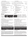
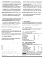
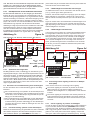
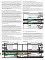
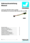
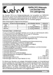
Abbildung 1
Figure 1
Decoder 5254
decoder 5254
6-fach-Flachbandkabel 6-way flat cable
ZF Zusatzfunktion
AF auxiliary
function
Pin 1 pin 1
LR Licht rückwärts
LV Licht vorwärts
G2 Gleisanschluss 2
G1 Gleisanschluss 1
M2 Motoranschluss 2
M1 Motoranschluss 1
0…7
1…2
1…4
0
LB light backward
LV light forward
T2 track connection 2
T1 track connection 1
M2 motor connection 2
M1 motor connection 1
2. Wichtige Hinweise
2. Important Information
Lesen Sie vor der ersten Benutzung des Produktes bzw. dessen Einbau diese Bedienungsanleitung aufmerksam durch.
Read the operating instructions carefully before using the
product for the first time or assembling it.
2.1. Das Produkt richtig verwenden
2.1. Using the Product correctly
Dieser Lokomotivdecoder ist bestimmt
This locomotive decoder is intended
zum Einbau in Modelleisenbahnen
for installation in model locomotives
zum Betrieb an einem zugelassenen Modellbahntransformator bzw. an einer damit versorgten digitalen Modellbahnsteuerung
for operation with an authorized model railroad transformer
or a digital model railroad control system connected to one
zum Betrieb in trockenen Räumen
Jeder darüber hinausgehende Gebrauch gilt als nicht bestimmungsgemäß. Für hieraus resultierende Schäden haftet der
Hersteller nicht; das Risiko hierfür trägt allein der Benutzer.
for operation in a dry area
Using the product for any other purpose is not approved and is
considered incorrect. The manufacturer cannot be held responsible for any damage resulting from the improper use of this
product; liability in such a case rests with the user.
W
k
r
s
S
t
a
f
V
i
s
S
R
H
b
g
z
n
3
N
b
w
D
g
R
g
n
t
V
H
J
t
b
a
B
s
l
3
N
a
K
u
v
d
n
b
Der Decoder darf nur in Modellbahnen eingesetzt werden!
The decoder is only allowed to be put in model railways!
Achtung: Ein Betrieb des Decoders auf analogen
Wechselstromanlagen ist nicht zulässig! Die hohe
Spannung des Umschaltimpulses führt zur Zerstörung des
Decoders.
Please note: This decoder is not suitable for operation
with conventional AC supply! The high voltage of the pulse
for change of direction will cause the destruction of the
decoder.
3. Einbau des Decoders
3. Installing the Decoder
3.1. Vorbereitung
3.1. Preparation
Es können nur Lokomotiven mit einem Digitaldecoder ausgerüstet werden, die im Gleichstrombetrieb einwandfrei funktionieren. Besonders im Digitalbetrieb ist eine sichere und unterbrechungsfreie Stromaufnahme wichtig. Ersetzen Sie verschlissene Kohlebürsten und defekte Lämpchen und reinigen Sie die
Radschleifer. Der Decoder sollte an einer Stelle in der Lok eingebaut werden, wo mit der geringsten Wärmeentwicklung zu
rechnen ist.
Only locomotives, which run smoothly in analogue mode,
should be equipped with a digital decoder. A secure and uninterrupted current pickup is important especially in digital mode.
Change worn coal brushes and defect lights and clean wheel
pick-ups. The decoder should be installed inside the locomotive
in such a way as to avoid overheating.
D
5
Tools: For installing the decoder please use a soldering iron
with 30 Watts max. (if possible with temperature control), elec-
E
S
2
B
s
D
h
u
A
F
d
5
³
A
A
A
A
)
)
)
)
)
)
)
)
Werkzeug: Verwenden Sie für den Decodereinbau einen Lötkolben mit max. 30 Watt Leistung (wenn vorhanden mit Temperaturregelung), Elektroniklötzinn (kein Lötfett) sowie Seitenschneider (zum Kürzen der Anschlussdrähte) und kleine
Schraubendreher. Zusätzlich benötigen Sie Isolierband (um Metallteile der Lok abzukleben) und doppelseitige Klebepads (z.B.
aus dem Lokdecoder-Einbauset 6819 von Viessmann) zum Befestigen des Decoders.
Vor dem Einbau des Decoders ist der Motor vollständig zu
isolieren, d.h. es dürfen keine elektrischen Verbindungen zwischen Motoranschlüssen und Radschleifer existieren. Merken
Sie sich, welcher Motoranschluss mit dem rechten bzw. linken
Radschleifer verbunden war.
Hinweis zu älteren Loks der Firma Fleischmann: Häufig ist
bei diesen Loks der Motorschild ein Teil der Motorstromversorgung und mit einem der Radschleifer verbunden. Um den Motor
zu isolieren, müssen Sie diese Verbindung auftrennen oder einen neuen Lagerschild einsetzen.
3.2. Strombelastbarkeit
Neben den gewünschten Funktionen und dem verfügbaren Einbauraum ist die Stromaufnahme des Lokmotors unter Volllast
wesentlich bei der Auswahl des richtigen Decoders.
Der Decoder 5254 kann einen Motorstrom von 1 A liefern. Angaben über die Stromaufnahme der Lok beziehen sich in der
Regel auf eine Spannung von 12 oder 14 V. Liegt die Versorgungsspannung Ihrer Digitalzentrale höher, steigt die Stromaufnahme an und kann so eventuell den Wert von 1 A überschreiten. Für den Betrieb von Fahrzeugen der Baugröße Z wird eine
Versorgungsspannung von ca. 10 bis 12 V, für Baugröße N bis
H0 eine Spannung von 14 bis 16 V empfohlen.
tronic solder (no soldering paste) and side cutters (to shorten
the leads) and small screw drivers. You also need insulation
tape (to cover any metal parts of the locomotive) and double
sided tape (such as included in Viessmann locomotive decoder
installation set article # 6819) to fasten the decoder.
Before installing the decoder you have to completely insulate
the motor, which means there should not be any electrical connection between motor and wheel pick-ups. Don't forget which
motor terminals were connected with the right or left wheel pickup.
Advice for older Fleischmann locomotives: Often in these locomotives the motor shield is part of the motor's power supply
and therefore connected with one of the wheel pick-ups. To insulate the motor you have to cut off this connection or replace
the motor shield.
3.2. Maximum Current Load Capacity
Besides the desired functions and the available installation
space the current draw of the motor under full load determines
the selection of a suitable decoder.
The decoder 5254 supplies a motor current of 1 A. Values regarding current draw of the locomotives generally refer to a voltage of 12 or 14 V. Is the supply voltage of your command station higher, the current drawn rises and could potentially exceed
the permitted value of 1 A. For operating Z gauge the recommended supply voltage is 10 to 12 V, for N to H0 gauge the recommended supply voltage is 14 to 16 V.
Each light output of the decoder 5254 can supply 300 mA. The
total current load capacity of the decoder 5254 is 1 A. If the motor draws e.g. 0.9 A, then the total current available for all the
light outputs is 100 mA.
Jeder Lichtausgang des Decoders 5254 kann maximal 300 mA
treiben. Die Gesamtstrombelastbarkeit des Decoders 5254
beträgt 1 A. Benötigt der Motor z.B. 0,9 A, stehen für die Lichtausgänge also insgesamt nur noch 100 mA zur Verfügung.
Please observe the maximum load capacity of the decoder and
each individual output. If excess current is drawn, the overload
protection will switch off the decoder.
Beachten Sie die maximale Belastbarkeit des Decoders und
seiner einzelnen Ausgänge. Bei Überlastung schaltet die Überlastsicherung den Decoder ab.
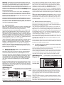
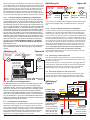
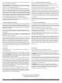
3.3. Installing the Decoder 5254 in Locomotives with Interface as per NEM 651 "S"
3.3. Einbau des Decoders 5254 in Loks mit NEM 651 "S"Schnittstellenbuchse
Nach dem Öffnen der Lok entfernen Sie den Brückenstecker
aus der Schnittstellenbuchse auf der Schaltplatine der Lok.
Kürzen Sie das 6-fach Flachbandkabel des Decoders auf 5 mm
und ziehen Sie die Isolierung des Kabels vorsichtig ab. Wenn
vom Hersteller der Lok nicht anders angegeben, stecken Sie
den Decoder mit den 6 Drahtenden mit der Bestückungsseite
nach oben entsprechend Abbildung 2a in die Schnittstellenbuchse.
Bei den Schnittstellenbuchsen einiger Hersteller dürfen die Anschlüsse nur 3 mm lang sein. Für diese Buchsen sind u.U. die
Drahtenden für einen festen Kontakt zu dünn. Biegen Sie deshalb bei diesen Buchsen die letzten 2 mm der Anschlussdrähte
um (siehe Abbildung 2b).
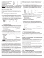
Abbildung 2b
Figure 2b
Decoder
5254
Schnittstellenbuchse auf Lokleiterplatte
interface socket on locomotive circuit
board
Ansicht von oben
view from above
decoder
5254
Once you have opened the locomotive remove the bridge plate
from the interface socket on the circuit board.
Shorten the flatcable of the decoder to a length of 5 mm and remove carefully its insulation. If the instruction of the locomotive
do not indicate otherwise, insert the decoder with the component side up according to figure 2a into the interface socket.
Abbildung 2a Lokleiterplatte mit Schnittstellenbuchse
Figure 2a
locomotive circuit board with interface socket
Decoder 5254
decoder 5254
Ansicht von oben
view from above
Some locomotive manufacturer use an interface socket for
which the connecting wire leads may only be 3 mm long. For
these sockets the wire leads are potentially too thin. In these
cases bend the last 2 mm of the wires towards the decoder.
(see figure 2b.)
Markierung
marking
Some locomotives have a so called soldering interface. These
interfaces have 6 soldering pads instead of an interface socket.
(see figure 2c.)
Einige Lokomotiven haben so genannte Lötschnittstellen. Diese
Schnittstellen haben keine Schnittstellenbuchse, sondern 6 Löt-
First put some soldering tin onto the soldering pads and the
wire ends - using only little heat to avoid softening the soldering
Pin 1 pin 1
*
3
flächen, an denen die Anschlussdrähte des Decoders angelötet
werden müssen (siehe Abbildung 2c).
Vor dem Anlöten des Decoders verzinnen Sie die Lötflächen auf
der Lokplatine und die Drahtenden des Decoders. Hierbei
dürfen die Drahtenden nur sehr kurz erwärmt werden, da sich
sonst die Lötstellen am Decoder lösen. Die Anschlussdrähte
löten Sie dann an die jeweiligen Lötflächen. Auch hierbei dürfen
die Drähte und Lötstellen nur sehr kurz mit dem Lötkolben erwärmt werden, damit nur das Lötzinn der Lötstelle auf der Platine der Lok fließt und nicht das Lötzinn am Decoder. Am besten hierzu den jeweiligen Draht mit einer Pinzette festhalten und
nach unten drücken - dadurch wird Wärme abgeleitet.
Loks mit NEM 651-Schnittstelle haben im Bereich der Schnittstelle Aussparungen zur Aufnahme des Fahrzeugdecoders.
Auch ist die Unterseite des Decoders mit einer isolierenden
Lackschicht überzogen. Deshalb sind normalerweise keine
weiteren Maßnahmen wie z.B. Isolieren usw. erforderlich. Überprüfen Sie trotzdem, ob irgendwelche Metallteile den Decoder
berühren könnten und kleben Sie in der Nähe befindliche Metallteile mit Isolierband ab.
Die Bauteile des Decoders dürfen auf keinen Fall Metallteile des Lokfahrgestells oder des Gehäuses berühren.
Dadurch verursachte Kurzschlüsse führen zur Zerstörung
des Decoders.
Wickeln Sie den Decoder nicht in Isolierband ein, da hierdurch
die Wärmeabfuhr behindert wird. Der Decoder könnte sonst
thermisch überlastet werden.
3.4. Einbau des Decoders 5254 in Loks ohne NEM 651 "S"Schnittstellenbuchse
Vor dem Einbau sind der Motor und die Motoranschlüsse komplett gegen das Fahrwerk der Lok und die Stromaufnehmer
(Radschleifer) zu isolieren. Merken Sie sich, welcher Motoranschluss mit dem rechten bzw. linken Radschleifer verbunden
war.
Das Flachbandkabel muss vor dem Einbau des Decoders mit
einem feinen Messer in einzelne Adern "zerlegt" werden. Möglicherweise ist es einfacher, das Flachbandkabel durch flexible
Litzen aus dem Lokdecoder-Einbauset (Viessmann Art.-Nr.
6819) in den NEM-Farben zu ersetzen.
1) Vor Beginn der Arbeiten sollten Sie sich an einer Heizung
bzw. an einem Wasserrohr entladen, um den Decoder vor
Beschädigung durch elektrostatische Entladung zu schützen.
Tragen Sie beim Decodereinbau Kleidung aus Baumwolle!
2) Verbinden Sie den Anschlussdraht G1 ("Gleisanschluss 1",
rot) des Decoders mit dem rechten Radschleifer, den Anschlussdraht G2 ("Gleisanschluss 2", schwarz) des Decoders
mit dem linken Radschleifer der Lok.
points of the decoder. Then solder the wires to the soldering
pads by only touching very briefly with the soldering iron avoiding again to soften the soldering points on the decoder. Use
Abbildung 2c
Figure 2c
Decoder 5254
decoder 5254
Lokleiterplatte mit Löt-Schnittstelle
locomotive circuit board with soldering
Interface
Ansicht von oben
view from above
small tweezers to hold down the wire and to absorb some of the
excessive heat.
Locomotives with the NEM 651-interface provide next to the
interface enough space for the decoder and the bottom side of
the decoder is covered with insulating laquer. Hence no separate insulation or other work is required. To be on the safe side,
check if any metal parts could touch the decoder and insulate
such metal parts with insulating tape.
Under no circumstances should components of the
decoder touch any metal parts of the chassis or the
locomotive body. Resulting short circuits will destroy the
decoder.
C
m
3.4. Installing the Decoder 5254 in Locomotives without
Interface-socket as per NEM 651 "S"
Before you start, completely insulate the motor and its terminals against the chassis of the locomotive and the current pickups (wheel pick-ups). Remember which motor terminal was
connected with the right or left wheel pick-up.
6
The decoder flat cable has to be cut with a hobby-knife into single wires. It may be easier to replace the flat cable with flexible
wires in NEM colours contained in the Locomotive Decoder Installation Set (Viessmann article # 6819).
7
1) Before you start, you have to discharge any electrostatic
charge by touching a water tap (or radiator) to avoid damage
through an electrostatic discharge. Clothes made of cotton
are best suited for working with decoders.
8
2) Connect the wire T1 ("track connection 1", orange) from the
decoder to the right wheel pick-up, the wire T2 ("track connection 2", grey) from the decoder to the left wheel pick-up of
the locomotive.
3) Solder the wire M1 ("motor connection 1", red) to the motor
terminal, which was connected to the right wheel pick-up before installation. Solder the wire M2 ("motor connection 2",
black) to the motor terminal, which was connected to the left
wheel pick-up. The RFI suppression components, which
were connected to the motor before installation, may remain
in the circuit of the motor-leads.
4) Wird dieser Decoder in Fahrzeugen mit größeren Motoren
eingesetzt (TT, H0 bzw. größer), so muss eine Schutzdiode
SA20CA (Viessmann Art.-Nr. 6814, 5 Stück) entsprechend
der Zeichnung parallel zum Motor mit eingebaut werden.
4) To use this decoder in larger models (TT, H0 and larger) you
have to wire a protective diode into the motor leads parallel
to the motor; use type SA20CA (Viessmann article # 6814, 5
pieces per pack) as indicated in the drawing!
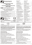
5) Der Decoder 5254 besitzt keine positive Versorgung für die
Lichtausgänge (blauer Draht bei NEM 652-Decodern). Die
Lampen werden statt dessen mit den Radschleifern nach
folgenden Varianten verbunden:
5) The decoder 5254 has no positive supply for the light outputs
(blue wire of H0 decoders). Instead, the lights are connected
with the wheel pick-ups according to either of the following
methods:
4
A
v
To avoid overheating, do not wrap the decoder with insulation
tape. Otherwise the decoder may be thermally overloaded.
3) Löten Sie den Anschlussdraht M1 ("Motoranschluss 1", orange) an den Motoranschluss, der vor Einbau des Decoders
mit dem rechten Radschleifer verbunden war. Löten Sie den
Anschlussdraht M2 ("Motoranschluss 2", grau) an den Motoranschluss, der vorher mit dem linken Radschleifer verbunden
war. Die Entstörelemente, die vor Einbau des Decoders mit
dem Motor Ihrer Lokomotive verbunden waren, können in der
Motorzuleitung verbleiben.
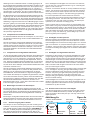
Sind die Lampenfassungen der Lokomotive gegen das
Fahrgestell isoliert, verwenden Sie am besten den in Ab-
A
If the light sockets of the locomotive are insulated against
the chassis (potential-free), wire them as shown in figure
4
D
w
s
a
s
d
H
S
e
g
e
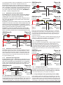
bildung 3a gezeigten Anschluss. Die Lampe für Licht vorne wird über den Draht LV ("Licht vorwärts", weiß) mit dem
Decoder 5254 verbunden. Der andere Pol wird mit dem
Radschleiferdraht G1 ("Gleisanschluss 1", rot) verbunden.
Die Lampe für Licht hinten wird über den Draht LR ("Licht
rückwärts", gelb) mit dem Decoder 5254 verbunden. Der
andere Pol wird mit dem Radschleiferdraht G2 ("Gleisanschluss 2, schwarz) verbunden. Bei dieser Anschlussart
funktionieren die Lampen auch im Analogbetrieb.
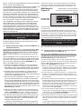
Abbildung 3a
Figure 3a
Licht vorne
front light
Licht hinten
back light
LV weiß
LF white
Ansicht von oben
view from above
Decoder 5254
decoder 5254
M
Figure 3b
Licht vorne
front light
6814
M2 grau
M2 grey
rot G1
red T1
In locomotives, where one pole of the light sockets is electrically connected with the chassis, wire the outputs as
shown in figure 3b. Please note, that with this wiring methode the light outputs don't work in analogue mode depending on the polarity of the track voltage.
Abbildung 3b
LR gelb
LB yellow
M1 orange
M1 orange
3a. The bulb for the front light has to be connected to the
wire LF ("light forward", white). The other pole has to be
connected to the T1 ("track connection 1", red) wheel pickup. Connect the back light to the wire LB ("light backward", yellow) and to the T2 ("track connection 2", black)
wheel pick-up wire. Wired in this manner the lights will
also work in analogue mode.
Licht hinten
back light
LV weiß
LF white
*
6814
Ansicht von oben
view from above
M2 grau
M2 grey
G2 schwarz
T2 black
Achtung: Motor
vollständig isolieren!
* Schutzdiode 6814 nur
für TT, H0 der größer!
Caution: Insulate the
motor completely!
* suppressor diode
6814 only for TT, H0
or larger!
In Lokomotiven, bei denen der eine Pol der Lampenfassungen mit dem Fahrgestell elektrisch verbunden ist, verwenden Sie den in Abbildung 3b gezeigten Anschluss der
Lichtausgänge. Bitte beachten Sie bei dieser Anschlussart, dass im Analogbetrieb je nach Polarität der Gleisspannung die Lichtausgänge nicht arbeiten.
6) Anschließend sollte noch einmal die gesamte Verdrahtung,
der Decoder und die Motoranschlüsse auf eventuelle Kurzschlüsse untersucht werden.
7) Der Decoder sollte in dem vom Lokhersteller vorgesehenen
Einbauplatz untergebracht werden. Ist dieser Platz nicht vorhanden, so können Sie den Decoder auch im Dachbereich
oder im Führerstand unterbringen.
8) Befinden sich Metallteile in der Nähe des Decoders, kleben
Sie diese mit Isolierband ab. Wickeln Sie den Decoder nicht
noch zusätzlich in Isolierband ein, da dadurch die Wärmeabfuhr behindert wird. Der Decoder kann sonst thermisch überlastet werden. Fixieren Sie den Decoder mit einem doppelseitigen Klebepad in der Lok.
Die Bauteile des Decoders dürfen auf keinen Fall Metallteile des Lokfahrgestells oder des Gehäuses berühren. Die
Motoranschlüsse dürfen keine Verbindung zu Radschleifern oder dem Lokfahrgestell haben. Dadurch verursachte
Kurzschlüsse führen zur Zerstörung des Decoders.
LR gelb
LB yellow
M1 orange
M1 orange
Decoder 5254
decoder 5254
rot G1
red T1
*
M
G2 schwarz
T2 black
Achtung: Motor
vollständig isolieren!
Caution: Insulate the
motor completely!
* Schutzdiode 6814 nur
für H0 oder größer!
* suppressor diode
6814 only for H0 or
larger!
Rot oder schwarz ist mit dem Lokfahrgestell verbunden.
Red or black wire is connected to the locomotive chassis.
6) Afterwards check the entire wiring, the decoder and the motor connections for possible short circuits.
7) The decoder should be put into the place designated for the
decoder by the locomotive manufacturer. Is there no specific
place, you can place the decoder in the roof area or in the
driver's cab.
8) Are there any metal parts close to the decoder, cover them
with insulation tape. Don't wrap the decoder in insulation tape
to avoid overheating. Fasten the decoder with a double sided
adhesive tape inside the locomotive.
Under no circumstances should components of the decoder touch any metal parts of the chassis or the locomotive
body. The motor terminals must not have any connections
to the wheel pick-ups or chassis. Resulting short circuits
will destroy the decoder.
4. Überprüfung des korrekten Einbaus
4. Checking for correct Installation
Der erste Test sollte auf einem Programmiergleis durchgeführt
werden. Bevor Sie die Lok auf das Programmiergleis stellen,
schalten Sie den Fahrstrom Ihrer SELECTRIX©-Zentraleinheit
aus ("Stop"). Danach lesen Sie im Programmiermodus die Einstellwerte des Decoders aus (siehe Absatz 5: Programmierung
des Decoders). Die Grundeinstellung sollte 01-542 sein.
The first test should be carried out on a programming track. Before placing the locomotive on the programming track, switch
the track current on the central unit of your SELECTRIX© system off ("stop"). Then read out the parameters. (refer to paragraph 5: Programming of the Decoder.) The base setting should
be 01-542.
Hat das Programmiergerät "Lesefehler" angezeigt, überprüfen
Sie nochmals die ordnungsgemäße Verdrahtung der Lok.
Should the command station display "read error" please check
the wiring of the locomotive once again.
Weitere Hinweise und Tipps zur Anwendung des Decoders
erhalten Sie im Internet unter:
www.viessmann-modell.de
Further hints for usage of the decoder you can find in the
internet:
www.viessmann-modell.de
5
Der Decoder 5254 zeigt eine falsche Verdrahtung bzw.
Kurzschluss durch "Lesefehler" am Programmiergerät an.
The decoder 5254 indicates wrong wiring or a short circuit
with the Message "Read Error" on the programming unit.
Bei korrekter Verdrahtung sollte ein surrendes Geräusch
des Motores, verursacht durch die Programmierimpulse,
zu hören sein.
Is the wiring correct, you can hear a noise from the motor,
caused by the programming pulses.
Sind die Motoranschlüsse mit den Lichtanschlüssen
vertauscht, leuchten die Stirnlampen kurz. Hierbei zeigt
das Programmiergerät keinen "Lesefehler" an.
Wahrscheinlich ist der Decoder umgekehrt eingebaut.
Ist bis hier alles richtig, sollten Sie die Lok mit dieser Einstellung
in Betrieb nehmen und zunächst kontrollieren, ob alle Funktionen (wie z.B. Motordrehrichtung, Licht usw.) ordnungsgemäß
arbeiten.
Versuchen Sie nun, die Lok unter der oben ausgelesenen
Adresse im unteren Fahrstufenbereich zu fahren (Licht und
Horn vorher ausschalten) und überprüfen Sie die Fahrtrichtung
der Lok. Stimmt sie nicht, sind die Motoranschlüsse M1 und M2
vertauscht. Jetzt können die Lichtfunktionen getestet werden.
Stimmt die Beleuchtung der Lok nicht mit der Fahrtrichtung
überein, sind die Lichtanschlüsse LV und LR vertauscht. Entweder Sie korrigieren die vertauschten Anschlüsse, oder Sie vertauschen diese Anschlüsse elektronisch über die erweiterten
Einstellungen.
Stoppt die Lok beim Einschalten der Beleuchtung oder der Zusatzfunktion, so liegt ein Kurzschluss in der Verdrahtung oder
eine Überlastung der Lichtausgänge bzw. der Zusatzfunktion
vor. Eine Überlastung kann z.B. bei hohen Digitalspannungen
durch den Einschaltstrom von Glühlampen entstehen. Schalten
Sie falls nötig einen Widerstand von 22 Ohm / 0,25 W zwischen
Lämpchen und entsprechendem Decoder-Ausgang.
Spricht der Kurzschlussschutz beim Beschleunigen der Lok an,
ist eventuell die Versorgungsspannung des SELECTRIX©-Systems zu groß. Die normale Versorgungsspannung sollte für Z
bei ca. 10 bis 12 V und für N bis H0 bei ca. 14 bis 16 V liegen.
Nach dieser ersten Kontrolle können Sie die Parameter der Lok
Ihren Bedürfnissen anpassen (Lokadresse, Motorregelung ... ).
5. Programmierung des Decoders
Der Viessmann-Decoder 5254 kann durch Programmierung an
Ihre Lokomotive und das von Ihnen gewünschte Betriebsverhalten angepasst werden. Folgen Sie bei der Programmierung
den Hinweisen in der Betriebsanleitung Ihres SELECTRIX©Systems. Zur Programmierung darf sich auf dem Programmiergleis nur das zu programmierende Fahrzeug befinden.
©
5.1. Standard-Parameter für SELECTRIX -Betrieb
Lokadresse
adrs
1 ... 111
Höchstgeschwindigkeit
velo
1 ... 7
Anfahr-/Bremsverzögerung
acce
1 ... 7
Motorimpulsbreite
impw
1 ... 4
Anzahl Bremsabschnitte
stop
1/2
(1)
(5)
(4)
(2)
(1)
Achtung: Adresse 00 nicht verwenden! (...) = Werkseinstellung
5.1.1.
Beschreibung der Standard-Parameter
Lokadresse: Als Lokadresse können alle Adressen Ihres
©
SELECTRIX -Systems verwendet werden, die nicht zum
Stellen von Weichen o.ä. oder zur Rückmeldung verwendet
werden. Die Adresse 00 ist zum Programmieren der erweiterten Einstellungen (siehe Abschnitt 5.3.) reserviert.
©
Je nach verwendetem SELECTRIX -System stehen jedoch
nur die Adressen 1 bis 103 zur Verfügung. Die Adressen 104
bis 111 sind dabei für die Programmierung der Lokdecoder
bzw. für Sonderfunktionen reserviert und können nicht für
den Betrieb verwendet werden. Hinweise hierzu entnehmen
©
Sie bitte der Betriebsanleitung Ihrer SELECTRIX -Zentrale.
6
If the motor leads and the leads to the lights are
exchanged, the lights of the locomotive will light briefly the programming unit does not show "Read Error".
Probably the decoder has been mounted upside down.
If everything is ok now you may test the functionality (e.g. direction of motor revolutions, lights, etc.).
Now try to operate the locomotive under the address, which has
been read out above, at the lower speed steps (initially switch
off all functions) and check the direction of travel. If not correct,
the motor connections M1 and M2 are swapped. Now you can
test the lights and auxiliary functions. If the headlights don't
match the direction of travel, the connecting wires of the lights
LF and LB are swapped. You may either change the connecting
wires or you can correct this electronically using the extended
parameter setting.
If the locomotive stops when the lights or the extra functions are
switched on, there is a short circuit in the wiring or an overload
of the light or auxiliary function outputs. An overload can occur
for example through high digital voltages and the starting current of the bulbs. If necessary, put a resistor of 22 ohms / 0.25
W between the light bulb and the appropriate output.
If the overload protection trips during acceleration, the supply
©
voltage of your SELECTRIX system may be too high. The supply voltage for Z gauge should be between 10 and 12 V and for
N to H0 gauge between 14 and 16 V.
After this initial test you may adapt the settings to match your
own requirements (e.g. address, load control, etc.).
5
F
s
5. Programming of the Decoder
Viessmann decoder 5254 can be adapted to your locomotive
and the desired operating characteristics by programming. Fol©
low the instructions of your SELECTRIX system. During programming only the locomotive to be programmed is allowed to
be on the programming track.
©
5.1. Standard Parameters for SELECTRIX -Operation
address
adrs
1 … 111
maximum speed
velo
1…7
acceleration / deceleration
acce
1…7
motor pulse width
impw
1…4
number of brake sections
stop
1/2
Important: Do not use address 00.
(1)
(5)
(4)
(2)
(1)
5
D
l
j
R
D
v
L
5
D
d
n
(...) = factory setting
5
5.1.1.
Description of Standard Parameters
Address: The address of the locomotive can be any of the
addresses of your SELECTRIX© system, which are not used
for switching turnouts or for track occupancy detection, with
the exception of address 00 - this address is reserved to
programm the extended decoder settings.
Depending on your SELECTRIX© system only the addresses
1 to 103 are available. The addresses 104 to 111 may be reserved for decoder programming or special functions and are
not available for general use. Please refer to the information
provided with your SELECTRIX© system.
Maximum speed: It can be adjusted in 7 steps. Each step
increases the maximum speed by approx. 40 percent. A locomotive which drives 100 (model) km/h with maximum speed
4 will drive up to approx. 140 (model) km/h with maximum
speed 5 and up to approx. 196 (model) km/h with a maximum speed of 6.
Acceleration / deceleration: This influences the reaction
D
0
a
u
5
D
0
a
)
)
)
)
)
Höchstgeschwindigkeit: Sie kann in 7 Stufen verändert
werden. Pro Stufe erhöht sich die Höchstgeschwindigkeit der
Lok um ca. 40 %. Eine Lok, die bei Höchstgeschwindigkeitsstufe 4 maximal 100 (Modell-) km/h fährt, wird bei Höchstgeschwindigkeitsstufe 5 maximal ca. 140 (Modell-) km/h und
bei Stufe 6 maximal ca. 196 (Modell-) km/h fahren.
Anfahr-/Bremsverzögerung: Hiermit wird die Reaktion der
Lok auf Änderung der Fahrstufe in 7 Stufen von praktisch
verzögerungsfrei bis sehr träge (ca 0,5 Sekunden pro Fahrstufe) eingestellt. Dabei werden alle decoderinternen Zwischenstufen zwischen der Ausgangs- und der Endfahrstufe
sukzessive durchlaufen, was zu einer besonders weichen
Geschwindigkeitsänderung der Lokomotive führt.
Motorimpulsbreite: Mit dieser Einstellung wird die Impulsbreite des Decoders an die Erfordernisse des jeweiligen
Fahrzeugmotors angepasst. Normalerweise sollte die Impulsbreite auf 2 eingestellt werden. Ältere Motoren müssen
jedoch u.U. mit größerer Impulsbreite betrieben werden,
während Motoren neuerer Bauart, wie z.B. schräggenutete 5Pol-Motoren oder Glockenanker-Motoren mit Impulsbreite 1
betrieben werden können. Hierbei ist zu beachten, dass Motoren bei kleinerer Impulsbreite u.U. weniger Durchzugskraft
entwickeln, bei größerer Impulsbreite aber unruhig arbeiten.
Anzahl Bremsabschnitte: Hiermit legen Sie fest, ob Ihr
Fahrzeug in Bremsabschnitten bis zum Stillstand abgebremst
werden soll (einteilige Bremsabschnitte) oder mit Kriechfahrt
bis zum absoluten Halteabschnitt fahren soll (zweiteilige
Bremsabschnitte). Weitere Informationen im Abschnitt 6.9.
5.2. Einstellung für analogen Gleichstrombetrieb
Höchstgeschwindigkeit
velo
0
Für Analogbetrieb wird die Höchstgeschwindigkeit auf 0 gesetzt. Die anderen Parameter können beibehalten werden.
5.3. Erweiterte Einstellungen
Der Decoder 5254 bietet durch zusätzliche Parameter die Möglichkeit, sich noch besser an die speziellen Eigenschaften des
jeweiligen Fahrzeuges anzupassen (z.B. durch Einstellung der
Regelvariante für den Motor).
Durch die werkseitige Voreinstellung der erweiterten Kennwerte
verhält sich der Decoder entsprechend den bisher verfügbaren
Lokdecodern (z.B. 66830 der Fa. TRIX).
5.3.1.
Erweiterte Kennwerte
Die Einstellung der erweiterten Kennwerte wird über die Decoderadresse 00 vorgenommen. Deshalb kann diese Adresse
nicht als Lokadresse verwendet werden.
g
-
5.3.2.
Motor pulse width: This adjusts the decoder output pulse
width to the requirements of the individual motor. Normally a
pulse width of 2 should be used. However, for "older" motors
require possibly a larger puls width, while more "modern"
motors, like skew-wound 5-pole motors or coreless motors
should be operated with pulse width 1. Please note, small
pulse width possibly provide less power, while wide pulses
may cause that the motor works noisy or rough.
Number of brake sections: This determines, that the engine has to stop within the brake section (single brake section) or that the engine should crawl up to the second, powerless stop section (double brake sections). (Please refer to
part 6.9: Signal Brake Sections.)
5.2. Parameter for DC Operation
maximum speed
Velo
0
For DC operation use the parameter for maximum speed to 0.
All other parameters can be retained.
5.3. Extended Settings
The decoder 5254 can be adapted even better to the respective
model by means of additional parameters (e.g. by adjusting the
control characteristics for the motor).
Due to the factory settings the decoder will behave like older
SELECTRIX® decoders (e.g. TRIX article # 66830).
5.3.1.
Extended Parameters
The programming of the extended parameters utilizes the decoder address 00. This prevents this address as being used as
address for the locomotive.
5.3.2.
Read out of extended Parameters
This is accomplished by entering
0 0 1 1 1 1 programming key (the display shows 0 0 - 1 1 1)
which means:
special address
maximum speed
deceleration
pulse width
reading instruction
adrs
velo
acce
impw
stop
00
1
1
1
1
and pressing of the programming key!
Lesen der erweiterten Kennwerte
Das Lesen der erweiterten Werte erfolgt durch Eingabe von
0 0 1 1 1 1 Programmiertaste (das Display zeigt 0 0 - 1 1 1)
also
5.3.3.
Writing of extended Parameters
This is accomplished by entering
0 0 V A I 2 programming key (the display shows 0 0 = V A I)
Spezialadresse
Höchstgeschwindigkeit
Anfahr-/Bremsverzögerung
Motorimpulsbreite
Lesebefehl
adrs
velo
acce
impw
stop
00
1
1
1
1
und Drücken der Programmiertaste!
5.3.3.
time when changing the speed of the locomotive from immediate to very slow reaction (approx. 0.5 sec. per speed step).
This process uses all internal intermediate steps between the
starting and ending speedstep providing a very soft change
in speed of the locomotive.
Schreiben der erweiterten Kennwerte
Das Schreiben der Werte erfolgt durch Eingabe von
0 0 V A I 2 Programmiertaste (das Display zeigt 0 0 = V A I)
also
Spezialadresse
adrs
00
which means:
special address
interchanging connections
effectiveness of AFB
variants of motor control
writing instruction
adrs
velo
acce
impw
stop
and pressing of the programming key!
00
V
A
I
2
(4)
(1)
(3)
(...) = factory setting
Important: Reading and writing extended parameters overrides
the standard parameters (most importantly, the address will be
set to 0). Therefore you have to re-enter the standard parameters once you have completed programming the extended
parameters!
7
Vertauschung von Anschlüssen
Wirksamkeit der AFB
Variante der Motorregelung
Schreibbefehl
velo
acce
impw
stop
und Drücken der Programmiertaste!
V
A
I
2
(4)
(1)
(3)
(...) = Werkseinstellung
Achtung: Das Lesen und Schreiben der erweiterten Kennwerte
überschreibt die Standard-Parameter des Decoders (vor allem
wird die Adresse auf 00 umgeschaltet). Deshalb müssen nach
dem Bearbeiten der erweiterten Kennwerte die Standard-Parameter erneut eingegeben werden!
Hinweis: "Pfeift" der Motor nach der Inbetriebnahme, haben
Sie wahrscheinlich vergessen, die Standardwerte erneut einzugeben.
5.3.4.
Bedeutung der erweiterten Kennwerte
V - Vertauschung von Anschlüssen (velo): Sollten Sie bei
einer freien Decoderverdrahtung die Anschlüsse vertauscht
haben, können Sie diese elektronisch "zurechtrücken". Kontrollieren Sie zunächst, welche Anschlüsse vertauscht werden müssen (z.B. wenn das Licht in der verkehrten Fahrtrichtung leuchtet), und geben Sie dann die aus der folgenden Tabelle entnommene Zahl als Wert für V (Velo) ein:
Motor:
Licht:
Gleis:
x
x
x
x
x
x
x
x
-
x
-
x
-
x
x
-
Wert:
0
1
2
3
4
5
6
7 (4 = Standard)
(x bedeutet vertauschen)
A - Wirksamkeit der AFB (acce): Damit können Sie einstellen, ob die einprogrammierte Anfahr-/Bremsverzögerung nur
in den (Dioden-) Bremsabschnitten oder immer wirksam ist
(also auch bei der Steuerung von einem Handregler aus).
immer wirksam
nur in Halteabschnitten
1 (Standard)
2
Note: If the motor hums or generates a "whistling sound" you
have probably forgotten to re-enter the standard parameters.
5.3.4.
Description of Extended Parameters
Interchanging connections (velo): Should you have mixed
up any of the wires when installing the decoder you may correct this electronically. First check, which connections have
to be changed (e.g. if the headlights work the wrong way)
and then enter for V (Velo) the value as listed in the following
table:
e
R
D
s
d
l
s
N
6
motor:
light:
track:
x
x
x
x
x
x
x
x
-
x
-
x
-
x
x
-
D
k
s
value:
0
1
2
3
4
5
6
7 (4 = standard)
B
d
s
(x indicates: change connection)
Effectiveness of AFB (acce): This feature allows you to set
the programmed acceleration / deceleration for the brake
sections only or also when controlling the locomotive manually (with your hand held controller).
always activated
in brake sections only
1 (standard)
2
Other values are not permitted!
Variants of motor control (impw): This value allows you to
adapt the motor control characteristics to the particular motor. There is no general rule regarding which variant provides
the best control characteristics. Trial and error is the best
method to determine what works best.
very intensive
intensive
soft
very soft
B
s
H
d
D
B
s
D
A
L
f
1
2
3 (standard)
4
Note: For coreless motors the variant 4 is recommended, for
"older" motors the variant 2.
Andere Zahlen sind nicht zulässig!
I - Variante der Motorregelung (impw): Mit diesem Wert
können Sie die Regelung optimal an den Motor anpassen.
Es kann keine generelle Regel angegeben werden, welche
Variante das beste Regelverhalten ergibt, hier helfen nur
Fahrversuche.
sehr hart
hart
weich
sehr weich
1
2
3 (Standard)
4
Hinweis: Für Glockenankermotoren ist die Regelvariante 4,
für konstruktiv ältere Motoren die Variante 2 zu empfehlen.
6. Anwendungshinweise für den Decoder 5254
6.1. Anschaltung von Stirnlampen und Zusatzfunktionen
Stirnlampen und Zusatzfunktionen müssen immer über einen
Lichtausgang oder den Ausgang ZF an den Decoder 5254 angeschlossen werden. Zur Stromversorgung wird der zweite Pol
von Lampen usw. mit einem Radschleifer verbunden.
Ist ein Licht mit beiden Polen direkt an beide Radschleifer
angeschlossen, kann der Decoder nicht programmiert werden. Die Programmiereinrichtung zeigt beim Auslesen der
Decoderwerte Lesefehler an.
Für den Digital-Betrieb ist es unerheblich, mit welchem Radschleifer die einzelne Lampe oder Zusatzfunktion verbunden ist.
Allerdings sind für den Betrieb auf Gleichstromanlagen und für
die Verwendung von Signalbremsabschnitten zum Abbremsen
die Hinweise im Abschnitt 6.6. bzw. 6.7. und 6.8. zu beachten.
Viele Lokomotiven haben zusätzlich zu dem Spitzenlichtsignal
8
6. Application Hints for Decoder 5254
6.1. Connecting Headlights and Auxiliary Functions
Headlights and auxiliary functions always have to be connected
to a light output or the AF output of the decoder. The second
pole of a light etc. has to be connected to one of the wheel pickups.
If a light is connected directly to both wheel pick-ups, the
decoder can not be programmed, the programming unit will
always show read error.
For digital operation the lights or auxiliary function may be connected to either of the wheel pick-ups. However, if a locomotive
should also be operated on conventional DC layouts, or if the
layout contains signal brake sections, please refer to paragraphs 6.6. or 6.7. and 6.8. .
Many locomotives have additional red tail-lights, to be lit together with the white headlights.
The decoder 5254 can power up to 3 or 4 light bulbs per light
output. It has to be observed, that the lights, which should be lit
at the same time, have to be connected to the same wheel pickup. Otherweise the lights have to be connected via diodes
(Viessmann article # 6834, 10 pieces per pack), see the following examples.
6.1.1.
6
S
l
w
h
i
t
6
B
a
D
w
b
A
L
f
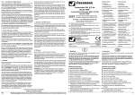
Headlight and red Tail-Light
Figure 4a, 4b and 4c show different ways to connect headlights
and red tail-lights. The difference is the connection to the wheel
pick-ups.
Figure 4a connects all lights to the engine chassis, which may
be connected to the left or right wheel pick-up.
6
D
d
i
n
)
l
-
ein rotes Schlusslicht, das bei Vorwärtsfahrt an der hinteren, bei
Rückwärtsfahrt an der vorderen Lokseite leuchten soll.
Der Decoder 5254 kann 3 bis 4 Loklampen je Lichtausgang ansteuern. Bei der Stromrückführung der einzelnen Lampen ist jedoch zu beachten, dass Lampen, die gleichzeitig leuchten sollen, an demselben Radschleifer angeschlossen werden müssen. Sonst müssen die Lampen über Dioden (Viessmann Art.Nr. 6834, 10 Stück) entkoppelt werden.
6.1.1.
Abbildung 4a
Bei Abbildung 4a sind alle Lampen mit der Lokmasse verbunden, die je nach Hersteller mit dem linken oder rechten Radschleifer verbunden ist.
Bei Abbildung 4c sind die Lampen über Kreuz mit den Radschleifern verbunden. Dadurch sind keine Dioden erforderlich.
Diese Anschaltung arbeitet auch im Gleichstrombetrieb richtig.
Abbildung 4c
Figure 4c
Licht vorne
front light
Licht hinten
back light
rot red
weiß white
6.1.2.
LR gelb
LB yellow
G2 schwarz
T2 black
Spitzenlicht nach Schweizer Art
Schweizer Lokomotiven haben eventuell zusätzlich zum Dreilicht-Spitzensignal rechts hinten ein weißes Rücklicht, selbst
wenn die Lok einen Zug zieht. Einige Lokmodelle haben deshalb 2 Glühlampen vorne und hinten, von denen jeweils eine
immer leuchten muss, die andere wechselt mit der Fahrtrichtung (siehe Abbildung 4d).
Licht vorne
front light
Figure 4b
Licht hinten
back light
4x Diode 6834
rot red
rot red
weiß white
weiß white
G1 rot
T1 red
LV weiß
LF white
LR gelb
LB yellow
G2 schwarz
T2 black
Figure 4b connects both front lights with pick-up T1 while the
back lights are connected to T2. The lights have to be connected via diodes with the decoder outputs, the cathode of the diodes (the side of the diode with the marking ring) showing towards the decoder.
Figure 4c connects the lights crosswise with the wheel pick-ups.
In doing so, diodes are not required. This wiring will also work
correctly operating the locomotive on DC layouts.
Headlight the Swiss Way
Swiss locomotives are equipped with a white tail-light in addition
to the three headlights even if cars are coupled to the loco.
Some model locos have 2 white bulbs for each direction, the
front left and back right always to be lit, the others depending on
the direction of travel. (Refer to figure 4d.) If all lights are connected to the same wheel pick-up, the dark marked diodes are
not required.
Abbildung 4d
Licht vorne
front light
Figure 4d
Licht hinten
back light
6x Diode 6834
weiß white
6.1.3.
LR gelb
LB yellow
Abbildung 4b
6.1.2.
LV weiß
LF white
weiß white
LV weiß
LF white
Bei Abbildung 4b sind die vorderen Lampen z.B. mit dem Radschleifer G1 verbunden, die hinteren mit dem Radschleifer G2.
Hierbei sind die Lampen über Dioden zu entkoppeln. Die Dioden müssen hierbei mit der Kathode (= Markierungsring an der
Diode) in Richtung Decoder angeschlossen werden.
weiß white
rot red
weiß white
Die Abbildungen 4a, 4b und 4c zeigen verschiedene Möglichkeiten, Stirnlampen und Rücklicht anzuschließen. Die Unterschiede liegen in der Art der Stromrückführung.
G1 rot
T1 red
Licht hinten
back light
rot red
Spitzenlicht und rotes Schlusslicht
rot red
Figure 4a
Licht vorne
front light
weiß white
Spitzenlicht bei Rangierloks
Bei Rangierfahrten sollen, unabhängig von Fahrtrichtung und
angekoppelten Waggons, immer beide Spitzenlichter leuchten.
Dies kann für Rangierloks gemäß Abbildung 4e nachgebildet
werden. Die dunkel markierten Dioden können entfallen, wenn
beide Lampen mit demselben Radschleifer verbunden sind.
Abbildung 4e
Licht vorne
front light
Figure 4e
4x Diode 6834
weiß white
G1 rot
T1 red
Licht hinten
back light
weiß white
LV weiß
LF white
LR gelb
LB yellow
G2 schwarz
T2 black
6.2. Anschaltung von LED-Stirnlampen
Die Arbeitsweise und die elektrischen Eigenheiten von Leuchtdioden (LEDs) sind anders als bei Glühlampen. Die meisten der
in Modellbahnfahrzeugen verwendeten Glühlampen haben einen der bei Modellbahnen verwendeten Versorgungsspannung
Schlusslicht weiß
tail-light white
G1 rot
T1 red
6.1.3.
Schlusslicht weiß
tail-light white
LV weiß
LF white
LR gelb
LB yellow
G2 schwarz
T2 black
Headlight with Switchers
A locomotive used to switch cars, both headlights should be lit
regardless of direction and cars coupled to the loco. Figure 4e
shows the appropriate wiring. If both headlights are connected
to the same wheel pick-up, no diodes are required.
6.2. Using Headlights with Light Emitting Diodes (LEDs)
Light emitting diodes work different as light bulbs do. The electrical characteristics are entirely different. Most light bulbs used
in model railways have an internal resistance appropriate to the
voltages used. They usually consume a current of approximately 40 mAmps. The direction of current is immaterial. While being
9
angepassten Innenwiderstand, wodurch diese jeweils ca. 40 mA
Strom verbrauchen. Die Stromrichtung ist dabei unbedeutend.
Beim Einschalten einer Glühlampe wird wegen des sehr niedrigen Kaltwiderstandes jedoch kurzzeitig ein Strom eines vielfachen des normalen Stromes gebraucht.
Übliche LEDs hingegen benötigen je nach Bauart und Farbe
eine Spannung von ca. 2 Volt bei einem maximalen Strom von
10 bis 20 mA. Hierbei muss der Strom immer von der Anode zur
Kathode fließen, in umgekehrter Richtung leuchtet die LED
nicht. Anders als bei Glühlampen benötigt eine LED beim Einschalten keinen überhöhten Strom.
Eine Eigenheit ist, dass die meisten LEDs schon weit unter 10
mA eine ausreichende Leuchtkraft erzielen. Wichtig ist aber,
dass LEDs praktisch keinen Innenwiderstand haben. Deswegen
dürfen sie nie direkt an eine Versorgungsspannung, sondern
nur über einen Vorwiderstand angeschlossen werden.
switched on, a light bulb draws for a very short time up to tenfold of the normal current, because when cold, the internal resistance of a light bulb is very low.
The usual LEDs, depending on technology and colour, require
approx. 2 Volt and draw a current of 10 to 20 mAmps. The current has to flow from the anode to the cathode. In reverse direction however a LED is not illuminated. Unlike light bulbs, LEDs
do not draw excessive current when being switched on.
Another characteristic of a LED is that it produces enough light
already with current well under 10 mAmps. Important is, however, that a LED practically does not have an internal resistance. It may never be connected directly to a current source. It
must always be connected via a current limiting resistor.
Several LEDs may be connected in series to a common limiting
resistor, consuming only once the LED current.
LEDs können hinter einem Vorwiderstand in Serie geschaltet
werden, wodurch nur einmal der LED-Strom benötigt wird.
With many locomotives, however, several LEDs of the same
type may be connected in parallel behind a common limiting
resistance using a multiple of the single LED current.
Es gibt allerdings auch Loks, die in Baugruppen hinter einem
Vorwiderstand mehrere gleiche LEDs parallel geschaltet haben.
Hierdurch vervielfacht sich der Strombedarf entsprechend der
Anzahl parallel geschalteter LEDs.
6.2.1.
6.2.1.
LED-Spitzenlicht
Figure 5a shows how to wire headlights built up using LED units
of 3 LEDs each. If the LEDs are wired in series, the LED current
is drawn only once.
Some loco manufacturer prefer to wire the LEDs in parallel,
having the advantage in DC operation of the LED light being
already visible with a track voltage under 3 Volt. Hence the
limiting resistor has a very low resistance value.
Einige Hersteller sind dazu übergegangen, mehrere LEDs parallel zu schalten, damit das Licht im Analogbetrieb schon bei
Fahrspannungen unter 3 Volt leuchtet. Dementsprechend hat
der Vorwiderstand R einen sehr niedrigen Wert.
Operated digitally with very much higher track voltage the LEDs
might be lit extremely bright, potentally they may be destroyed.
Bei den gezeigten Schaltungen müssen die Vorwiderstände R
dem gewünschten Einsatz der Fahrzeuge entsprechend berechnet werden. Eventuell müssen die im Fahrzeug bereits eingebauten Vorwiderstände angepasst werden.
Hierbei ist zu berücksichtigen, dass bei LEDs in Serie der LEDStrom nur einmal für alle LEDs benötigt wird, während bei parallelen LEDs der LED-Strom pro LED benötigt wird.
Für Baugröße N bis H0 (mit einer empfohlenen Versorgungsspannung von 14 bis 16 Volt) sollten als Vorwiderstand R bei in
Serie geschalteten LEDs ca. 1.000 Ohm (= 1 kOhm), bei parallelen LEDs ca. 470 Ohm (bei einem Spitzenlicht mit 2 LEDs ca.
680 Ohm) verwendet werden.
Für Baugröße Z (Versorgungsspannung 10 bis 12 Volt) sollten
Sie bei LEDs in Serie ca. 680 Ohm, bei parallelen LEDs ca. 330
Ohm und bei Spitzenlicht mit 2 LEDs ca. 470 Ohm verwenden.
Abbildung 5a
Figure 5a
LED-Gruppe LED group
Licht vorne front light
R
G1 rot
T1 red
LV weiß
LF white
LED-Gruppe LED group
Licht hinten back light
LR gelb
LB yellow
G2 schwarz
T2 black
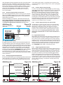
6.2.2. LED-Spitzenlicht und rotes Schlusslicht
Abbildung 5b ist ein Anschlussbild für Spitzenlicht mit rotem
Schlusslicht, bei denen die gelben (bzw. weißen) und roten
LEDs jeweils über separate Vorwiderstände angeschlossen
10
H
e
l
Ü
A
S
w
t
S
P
With all wiring shown, the limiting resistor R has to be selected
according to the use of the locomotive. Resistors already built
into the locomotives by their manufacturer may have to be
changed.
It has to be observed that with LEDs wired in series the LED
current is only consumed once while wired in parallel the LED
current is consumed per LED.
With gauges N to H0 with a recommended supply voltage of 14
to 16 Volt, the limiting resistor for LEDs wired in series should
be approximately 1 kOhm, wired in parallel approx. 470 Ohm
(with a LED group of only 2 LEDs: 720 Ohm).
With Z gauge with a recommended supply voltage of 10 to 12
Volt, the limiting resistor for LEDs wired in series should be
approx. 680 Ohm, wired in parallel approx. 330 Ohm (with a
LED group of only 2 LEDs: 470 Ohm).
6.2.2.
LED Headlight and red Tail-Light
Figure 5b shows the wiring of LED units with yellow resp. white
headlight and red tail-light. Both yellow resp. white and red
LEDs connected to a separate limiting resistor. The values of
the resistors are according to paragraph 6.2.1., the resistor for
Abbildung 5b
weiß
white
6
B
a
d
z
T
ü
s
r
6
F
l
Figure 5b
LED-Gruppe LED group
Licht vorne front light
R
6
B
f
n
A
LED Headlight
Abbildung 5a zeigt den Anschluss von Dreilicht-Spitzenlichtern
als LED-Gruppen. Die LEDs können dabei entweder in Serie
oder parallel geschaltet sein. Sind die LEDs in Serie geschaltet,
wird der LED-Strom für die 3 LEDs nur einmal benötigt.
Bei Digitalbetrieb ist aber die Fahrspannung wesentlich höher,
was dazu führen kann, dass die LEDs extrem hell leuchten oder
möglicherweise sogar zerstört werden können.
s
s
L
g
rot
red
LED-Gruppe LED group
Licht hinten back light
weiß
white
R
R
R
R
rot
red
6
G1 rot
T1 red
LV weiß
LF white
LR gelb
LB yellow
G2 schwarz
T2 black
D
d
s
sind. Die Werte der Vorwiderstände entsprechen denen des Abschnitts 6.2.1, jedoch können die Vorwiderstand bei gelben
LEDs etwas kleiner gewählt werden, da gelbe LEDs in der Regel leuchtschwächer sind als rote und weiße LEDs.
yellow LEDs may be somewhat lower because yellow LEDs are
less intense than red and white LEDs.
6.2.3.
An additional function can be connected to the decoder AF output, e.g. interior light, steam generator etc.
LED-Spitzenlicht mit zuschaltbarem Schlusslicht
Bei dem Decoder 5254 kann an den Ausgang für die Zusatzfunktion ZF (sog. Horn-Ausgang) eine Zusatzfunktion (z.B. Innenbeleuchtung, Dampfgenerator o.ä.) angeschlossen werden.
Hierbei ist allerdings zu beachten, dass dieser Ausgang nur einen Strom von maximal 50 mA zur Verfügung stellt. Eine Glühlampe z.B. hat einen so hohen Einschaltstrom, dass die interne
Überlastsicherung anspricht und den Decoder abschaltet.
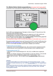
Abbildung 5c zeigt den Anschluss einer schaltbaren roten LEDSchlussbeleuchtung. Über die "Horn"-Taste des Fahrreglers
wird das rote Schlusslicht zum weißen Spitzenlicht fahrtrichtungsabhängig zugeschaltet. Hierzu ist jedoch ein zusätzlicher
Standard-PNP-Transistor vom Typ BC 558 o.ä. notwendig.
Abbildung 5c
Figure 5c
PNP-Transistor (z.B. BC 558) PNP transistor (BC 558 etc.)
t
LED-Gruppe LED group
Licht vorne front light
R
weiß
white
22 k
Ohm
Ansicht von oben
view from above
ZF Zusatzfunktion
AF auxiliary function
6.2.4.
LED-Gruppe LED group
Licht hinten back light
rot
red
weiß
white
R
R
R
R
rot
red
6.2.3.
LED Headlight and switchable red Tail-Light
However, this decoder output can only supply up to 50 mAmps.
When switching on a light bulb, it draws such a high current,
that the internal overload protection trips and cuts off the decoder.
Figure 5c shows how to wire switchable red LED tail-lights. Activating the auxiliary function on the controller the back red taillight, depending on the direction of travel, will be lit provided the
white headlights are activated.
6.2.4.
LED Headlights with Switchers
A locomotive used to switch cars, both white headlights should
be lit regardless of direction and cars coupled to the loco. Figure 5d shows, how to connect LED groups such, that by activating the auxiliary function on the controller, both headlights
are on regardless of the direction of travel. If the auxiliary function is off, the headlights are on according to the direction of
travel, provided the light function is activated on the controller.
To do this, you need an additional standard small power PNP
transistor (e.g. BC 558).
Abbildung 5d
LED-Gruppe LED group
Licht vorne front light
LR gelb
LB yellow
LV weiß
LF white
G1 rot T1 red
oder
or
G2 schwarz T2 black
oder
or
Decoder 5254
Masse ground
decoder 5254
Spitzenlicht bei Rangierloks
Figure 5d
2x
Diode
6834
LED-Gruppe LED group
Licht hinten back light
R
R
LV weiß
LF white
LR gelb
LB yellow
Ansicht von oben
view from above
G1 rot T1 red
oder
or
G2 schwarz T2 black
oder
or
Decoder 5254
Masse ground
decoder 5254
Bei Rangierfahrten sollen, unabhängig von Fahrtrichtung und
angekoppelten Wagen, immer die weißen Spitzenlichter auf beiden Seiten leuchten. In Abbildung 5d werden beide LED-Spitzenlampen unabhängig von der Fahrtrichtung über die "Horn"Taste des Fahrreglers eingeschaltet. Ist der Ausgang ZF nicht
über die "Horn"-Taste aktiviert, leuchten die Spitzenlampen entsprechend der Fahrtrichtung, sofern das Licht über den Fahrregler eingeschaltet wurde.
6.3. Connecting Interior Lighting in Rail Cars or Multiple
Units (MUs)
6.3. Anschluss der Innenbeleuchtung eines Triebwagens
There are two choices for connecting interior lighting:
Für den Anschluss einer Innenbeleuchtung gibt es zwei Möglichkeiten:
Die Innenbeleuchtung wird "parallel" zu den Stirnlampen des
Triebwagens angeschlossen. Die Innenbeleuchtung leuchtet
immer dann, wenn die Stirnlampen eingeschaltet sind (unabhängig von der Fahrtrichtung).
Die Innenbeleuchtung wird unabhängig von den Stirnlampen
an den Ausgang für Zusatzfunktion ZF angeschlossen. Die
Innenbeleuchtung leuchtet unabhängig von den Stirnlampen
und kann über die "Horn"-Taste am Fahrregler ein- bzw. ausgeschaltet werden.
6.3.1.
Innenbeleuchtung "parallel" zu den Stirnlampen
Damit die Innenbeleuchtung eingeschaltet wird, wenn entweder
das vordere Lämpchen oder das hintere Lämpchen leuchtet,
sind zusätzliche Dioden (z.B. Viessmann Art.-Nr. 6834, 10
ZF Zusatzfunktion
AF auxiliary function
The interior lighting is connected "in parallel" to the headlights of the rail car. The interior lighting is switched on,
whenever the headlights are on, independent of the direction
of travel.
The interior lighting is connected to the auxiliary function AF
output independent of the headlights. The interior lighting is
switched on and off using the "Horn" function button on your
controller.
6.3.1.
Interior Lighting "in parallel" to Headlights
In order to switch on the interior lighting when either headlight is
on you need two additional diodes (Viessmann article # 6834,
10 pieces per pack). Solder the cathode of the diode (marked
with a ring) to the yellow or white wire. Connect both anodes together to one of the poles of the interior lighting. Connect the
other pole of the interior lighting to the wheel pick-up. To avoid
11
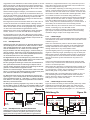
Stück) erforderlich. Die Kathoden der Dioden (Kennzeichnung
an der Diode durch einen Farbring) werden am Decoder sowohl
an LV (weiß) als auch an LR (gelb) angeschlossen. Die Anoden
werden zusammen an den einen Pol der Innenbeleuchtung angeschlossen. Der andere Pol der Innenbeleuchtung wird mit
dem Radschleiferanschluss verbunden (siehe Abbildung 6a).
Zur Vermeidung von Rückströmen müssen die Lampen für Licht
vorne und hinten ebenfalls über Dioden angeschlossen werden.
6.3.2.
Innenbeleuchtung unabhängig von Stirnlampen
Soll die Innenbeleuchtung unabhängig von den Stirnlämpchen
eingeschaltet werden, wird die Innenbeleuchtung an dem Ausgang Zusatzfunktion ZF angeschlossen. Allerdings können keine Glühlampen direkt an dem Ausgang ZF angeschlossen werden, da der Einschaltstrom der Lampen 50 mA bei weitem übersteigt. Deshalb ist hierfür ein PNP-Kleinleistungs-Transistor zur
Stromverstärkung (z.B. BC 558) entsprechend Abbildung 6b anzuschließen. Die Basis des Transistors wird mit dem Ausgang
ZF verbunden, der Kollektor wird mit dem Minuspol der decoderinternen Gleichrichtung direkt an der entsprechenden Diode
angelötet. Die Innenbeleuchtung wird an den Emitter des Transistors angeschlossen. Hierbei ist allerdings zu beachten, dass
dieser Anschluss ein Löten direkt an Bauteilen des Decoders
erfordert und bei unsachgemäßem Arbeiten ein Zerstören
des Decoders und einen Verlust der Garantie des Herstellers bedeuten kann.
Abbildung 6a
Licht vorne
front light
Figure 6a
Innenbeleuchtung
interior
light
Licht hinten
back light
LR gelb G2 schwarz
LB yellow T2 black
E
z
s
w
any cross-current between the headlights and the interior lights,
connect the headlight bulbs via additional diodes. (see figure
6a.)
A
ß
t
L
A
ß
G
G1 rot
T1 red
6.3.2.
LV weiß
LF white
4x Diode
6834
Interior Lighting independent of Headlights
Eine Innenbeleuchtung mit LEDs kann über einen entsprechenden Vorwiderstand direkt an den Ausgang ZF angeschlossen
werden.
In order to switch on the interior lighting independently from the
headlights, you connect the interior lights to the auxiliary function AF output. However, light bulbs cannot connected directly
to this output. The start-up current of a light bulb exceeds the 50
mA max. allowed for this output. To connect a light bulb to AF a
small power PNP transistor (e.g. BC 558) is used as lamp driver
as per figure 6b. The base of this transistor is connected to the
AF output, the collector is directly connected to the internal rectifying diode providing the minus voltage of the decoder. This
connection means soldering directly at components of the decoder requiring professional work to avoid destruction of
the decoder and loss of the manufacturers warranty.
Abbildung 6b
Interior lights using LEDs can be connected directly via a limiting resistor to the AF output.
Innenbeleuchtung
PNP-Transistor
(z.B. BC 558)
PNP transistor
(e.g. BC 558)
interior
light
Hier
anlöten
solder
here
Licht hinten
back light
Like interior lights a steam generator can be connected to the
AF output. However it has to be observed that this output only
provides up to 50 mA.
LR gelb
LB yellow
LV weiß
LF white
G1 rot
T1 red
Ansicht von oben
view from above
ZF Zusatzfunktion
Decoder 5254 G2 schwarz
AF auxiliary function decoder 5254
T2 black
6.4. Anschluss eines Dampfgenerators
Ein Dampfgenerator kann wie eine Innenbeleuchtung an den
Ausgang für Zusatzfunktion ZF (sog. Horn-Ausgang) angeschlossen werden. Auch hier ist zu beachten, dass dieser Ausgang nur einen Strom von maximal 50 mA zur Verfügung stellt.
Wird ein Dampfgenerator direkt am ZF-Ausgang betrieben,
spricht die interne Überlast-Sicherung an und schaltet den Decoder ab. Ein Dampfgenerator kann jedoch, wie Innenbeleuchtung mit Glühlampen, über einen handelsüblichen PNP Kleinleistungs-Transistor (z.B. BC 558) als Verstärker entsprechend
Abbildung 6b angeschlossen werden.
6.5.
Lichtfunktion in Steuerwagen
Für die Steuerung von Zusatzfunktionen stehen beim Decoder
5254 zwei Lichtausgänge und eine Zusatzfunktion zur Verfügung. Sollen weitere Funktionen in der Lok oder Lichtfunktionen
in einem Steuerwagen geschaltet werden, wird normalerweise
ein Funktionsdecoder eingesetzt. Es besteht jedoch auch die
Möglichkeit, einen normalen Lokdecoder z.B. für die Lichtsteuerung in einem Steuerwagen zu verwenden.
12
Using the AF output for a steam generator can trigger the overload protection cutting the decoder off. Like interior light bulbs
the steam generator can be connected using a small power
PNP transistor (e.g. BC 558) as driver as per figure 6b.
6.5. Directional Lights in a Cab Control Car
To control auxiliary functions the decoder 5254 has two light
outputs and one auxiliary output. Normally you would use a
function decoder to control additional functions in the locomo-
LED-Gruppe LED group
Licht hinten back light
LR gelb
LB yellow
Ansicht von oben
view from above
G1 (rot) in Richtung
Führerstand links,
G2 (schwarz)
rechts anschließen!
Connect T1 (red) in
direction of drivers
cab to the left, T2
(black) to the right!
I
d
b
S
s
u
s
s
v
J
i
g
b
s
2
a
L
S
s
a
b
n
s
S
d
B
t
Abbildung 7
Figure 7
Decoder 5254
decoder 5254
6
6
6.4. Connecting a Steam Generator
weiß
white
R
R
M1 orange
M1 orange
rot G1
red T1
6
rot
red
D
L
p
b
a
LV weiß
LF white
M2 grau
M2 gray
B
G
d
270
Licht vorne
front light
Figure 6b
A
f
M
l
2
d
S
G2 schwarz
T2 black
Widerstand
nach Programmierung entfernen!
Remove resistor
after programming!
6
U
s
b
N
d
s
0
d
!
r
!
Allerdings ist ein Lokdecoder hierfür nur bedingt geeignet, da
für die elektronische Einstellung des Decoders ein Motor an die
Motorausgänge angeschlossen sein muss. Es ist jedoch möglich, den Motor durch einen Widerstand von ca. 270 Ohm (=
270 R) an den Motorausgängen während der Programmierung
des Decoders zu simulieren. Für den normalen Betrieb des
Steuerwagens sollte dieser Widerstand jedoch entfernt werden.
Ein Steuerwagen hat normalerweise dieselbe Adresse wie die
zugehörige Lok. Die Führerstandsseite des Steuerwagens entspricht der Seite 2 der Lok, die Lampen der Fahrtrichtung rückwärts. Die Radschleifer sind dementsprechend anzuschließen.
Abbildung 7 zeigt den Anschluss einer LED-Baugruppe mit weißen (bzw. gelben) und roten LEDs. Die Gruppen haben separate Anschlüsse und Vorwiderstände. Die Kathodenseite der roten
LED-Gruppe wird über den Vorwiderstand mit LV (weiß), die
Anodenseite mit dem Radschleifer G1 (rot) verbunden. Die weißen bzw. gelben LEDs werden an LR (gelb) und Radschleifer
G2 (schwarz) angeschlossen.
6.6. Lokspitzenlicht und Gleichstrombetrieb
Im Gleichstrombetrieb leuchten die Loklampen nur, wenn sie in
der jeweiligen Fahrtrichtung mit dem rechten Radschleifer verbunden sind.
Sind die Loklampen entsprechend Abbildung 3a angeschlossen, d.h. die vorderen Loklampen sind mit G1 (rot) verbunden
und die hinteren mit G2 (schwarz), leuchten sie auch im Gleichstrombetrieb. Ebenso leuchten die Loklampen, wenn sie entsprechend Absatz 6.8. über Dioden mit beiden Radschleifern
verbunden sind.
tive or headlights and tail-lights in a cab control car. However,
you can also use a locomotive decoder e.g. for controlling the
lights in a cab control car.
However, a locomotive decoder is not fully suitable for this application. The electronic programming of the decoder requires a
motor load across the motor outputs. This load can be simulated using a resistor of approx. 270 Ohm during programming.
For normal operation this resistor should be removed.
The cab control car normally has the same address as the corresponding locomotive. The cab side of the control car is the
equivalent to the rear side of the locomotive. The wheel pickups have to be connected accordingly to this.
Figure 7 shows how to connect a group of red and white resp.
yellow LEDs. The groups of LEDs are equipped with separate
leads and separate resistors. The cathode of the red LED group
is connected via the limiting resistor to the decoder LF (white)
light output while the anode of these LEDs is connected to the
pick-up T1 (red). The white resp. yellow LED group is connected to LB (yellow) and T2 (black).
6.6. Headlights and DC operation
With DC operation the headlights only give light when connected to the right wheel pick-up as seen in the direction of travel.
If the headlights are connected according to figure 3a - the front
light is connected to T1 (red) and the back light is connected to
T2 (black) - they give light in DC operation. Also they give light if
connected according to paragraph 6.8. via diodes to both wheel
pick-ups.
6.7. Lokspitzenlicht und Signalbremsabschnitte
6.7. Headlights and Signal Brake Sections
Je nach Anschlussart leuchten die Loklampen beim Abbremsen
in einem Signalbremsabschnitt oder bei der Durchfahrt in Gegenrichtung nur in einer Lokrichtung. Leuchtet z.B. beim Abbremsen einer Lok in Lokrichtung 1 das Spitzenlicht, kann es
sein, dass das Lokspitzenlicht beim Abbremsen in Lokrichtung
2 im selben Bremsabschnitt nicht leuchtet. Das tritt bei Loks
auf, bei denen alle Loklampen mit demselben Radschleifer über
Lokmasse verbunden sind.
Depending on the method of connecting headlights they might
not give light during braking in signal brake sections or while
running through a brake section in the opposite direction. If e.g.
while braking a locomotive in forward direction the headlight is
illuminated it may not give light while braking in the same brake
section in the reverse direction of the locomotive. This happens
with locomotives with all lights connected to the same wheel
pick-up via the engine chassis.
Sind die Loklampen entsprechend Abbildung 3a angeschlossen (vordere Loklampe an G1, hintere an G2), leuchten sie unabhängig von der Lokrichtung beim Abbremsen im Signalbremsabschnitt, bei der Durchfahrt in Gegenrichtung jedoch
nicht. Wären die Loklampen umgekehrt angeschlossen, würden
sie bei der Durchfahrt leuchten, jedoch nicht beim Abbremsen.
If the headlights are connected according to figure 3a (front light
to T1, back light to T2) they give light while braking in brake
sections independent of the direction the locomotive is facing.
However, they don't give light while passing through a brake
section in opposite direction. If the light connections are
swapped, they give light while passing through the brake section but not while braking.
Sind jedoch die Loklampen entsprechend Absatz 6.8. über Dioden mit beiden Radschleifern verbunden, leuchten sie in
Bremsabschnitten immer - sofern das Loklicht über die Lichttaste am Fahrregler eingeschaltet ist.
If the headlights are connected according to paragraph 6.8. via
diodes to both wheel pick-ups, they will be illuminated in brake
sections regardless of the direction of travel, provided the light
is switched on by the controller.
6.8. Beidseitiger Anschluss von Stirnlampen
Der Decoder 5254 besitzt keine positive Versorgung für die
Lichtausgänge (blauer Draht bei NEM-652-Decodern). Die Lampen sind statt dessen normalerweise mit den Radschleifern verbunden. Diese Anschlussart ist bei Digitalbetrieb vollständig
ausreichend.
Bei Anlagen mit Signalbremsabschnitten oder beim Einsatz auf
Gleichstromanlagen leuchten jedoch bei dieser Anschlussart
die Stirnlampen u.U. nicht immer (siehe Absatz 6.6 und 6.7).
6.8.1.
Stromversorgung über 2 Dioden
Um Lampen an einem Lichtausgang mit voller Leistung anzuschließen, muss eine positive Versorgung für die Lichtausgänge
bzw. den ZF Ausgang mittels zweier Dioden (Viessmann Art.Nr. 6834, 10 Stück) entsprechend Abbildung 8a erzeugt werden. Dieser Anschluss wird im Folgenden als "blauer" Anschlussdraht bezeichnet. Es sollte aber hierbei bedacht werden,
6.8. Double sided Connection of Headlights
The decoder 5254 has no positive supply for the light outputs
(blue wire of NEM 652 decoders). Instead, the lights are normally connected to the wheel pick-ups. This fully suits normal
digital operation.
Abbildung 8a
"blauer" Anschlussdraht
"blue" wire
Figure 8a
Licht vorne
front light
Licht hinten
back light
Kathode
2x Diode
6834
Anode
G1 rot
T1 red
G2 schwarz
T2 black
LV weiß
LF white
LR gelb
LB yellow
13
dass die digitale Versorgungsspannung höher ist als bei analog
betriebenen Anlagen. Außerdem liegt der Arbeitspunkt dieser
Spannung höher als bei analogen Sinusspannungen. Hierdurch
können sich Glühlampen wesentlich stärker erwärmen, was zu
einer kürzeren Lebensdauer der Lampen führt und möglicherweise auch Kunststoffteile in deren Nähe verformen kann.
Eventuell ist den Glühlampen ein Widerstand von 22 bis 47
Ohm vorzuschalten.
6.8.2.
Stromversorgung direkt vom Decoder
Eine andere Möglichkeit der positiven Versorgung der Lichtausgänge und des ZF Ausgangs ist es, einen "blauen" Anschlussdraht entsprechend Abbildung 8b direkt an die decoderinterne
Gleichrichtung anzulöten.
Hierbei ist allerdings zu beachten, dass dieser Anschluss ein
Löten direkt an Bauteilen des Decoders erfordert, was bei unsachgemäßem Arbeiten ein Zerstören des Decoders und einen Verlust der Garantie des Herstellers bedeuten kann.
Abbildung 8b
Figure 8b
"blauer" Anschlussdraht
"blue" wire
Licht vorne
front light
Licht hinten
back light
Ansicht von oben
view from above
LV weiß
LF white
LR gelb
LB yellow
hier anlöten
solder here
6.9. Signalbremsabschnitte
Bei digital betriebenen Anlagen wird die Geschwindigkeit einer
Lok normalerweise über einen Fahrregler bestimmt. Auch das
Anhalten und Anfahren wird normalerweise über einen Fahrregler durchgeführt. Eine Zugbeeinflussung durch stromlose Gleisabschnitte z.B. bei Signalen würde hierbei zu einem abrupten
Anhalten führen. Der Decoder 5254 bietet jedoch die Möglichkeit durch eine Bremsdiode (Viessmann Art.-Nr. 6820, 10 Stück)
in Verbindung mit der Decodereinstellung für Anfahr- bzw.
Bremsverzögerung vor "Halt"-zeigendem Signal weich zu bremsen und bei anschließender "Fahrt"-Stellung des Signals wieder
weich anzufahren.
Einteilige Signalbremsabschnitte
Bei der Decodereinstellung für einteilige Signalbremsabschnitte
(siehe Abschnitt 5.1) bremst die Lok, nachdem sie bis zur letzten stromführenden Achse in den Signalbremsabschnitt einge-
Abbildung 9a
Positive Supply using 2 Diodes
6.8.2.
Positive Supply directly from the Decoder
An alternative to create the "blue" wire is to use the decoderinternal power supply for lights and devices connected to the
AF output by soldering the "blue" wire directly to internal
rectifier diode providing the positive voltage as per figure 8b.
6.9. Signal Brake Sections
6.9.1.
Bremsdiode 6820
brake diode 6820
Single Signal Brake Sections
With decoder setting for single brake sections (refer to part 5.1)
the loco brakes in brake sections down to standstill. The brake
distance depends on the speed step set by the controller and
the acceleration / deceleration setting of the decoder. This braking action is enabled by electrically insulating ( ) the brake
section and supplying power to this section via a brake diode
6820. If the signal shows a clear aspect, the brake diode 6820
is shortened by a signal contact, feeding the normal track power
into the brake section. In this case the loco travels through the
section without stopping or accelerates smoothly after a stop.
(see figure 9a.)
Figure 9b
Signalbremsabschnitt
signal brake section
6820
Bremsdiode 6820
brake diode 6820
Signalkontakt
signal contact
2-poliger Signalkontakt
2-pole signal contact
2 Trennstellen
2 track insulations
3 Trennstellen
3 track insulations
Fahrtrichtung
Fahrtrichtung
direction of travel
direction of travel
Bremsen braking
Bremsen braking
f
h
s
v
a
d
D
z
H
w
6
D
d
g
H
6
s
l
g
m
t
r
L
t
b
n
d
6
With digitally operated layouts the speed of a locomotive is normally controlled by a controller. Equally, braking and acceleration is done via the controller. Braking in front of stop-showing
signals by means of track sections without power would lead to
immediate stops. The decoder 5254, however, has the option of
braking smoothly at signals showing a stop aspect and accelerating smoothly after the signal clears by using brake diodes
(e.g. Viessmann article # 6820, 10 pieces per pack).
Figure 9a Abbildung 9b
Signalbremsabschnitt
signal brake section
14
6.8.1.
In order to operate light bulbs at full output, a positive supply
of the light outputs has to be generated by means of two diodes
(Viessmann article # 6834, 10 pieces per pack) as shown in
figure 8a. In the following this connection is called the "blue"
wire. However, the digital voltage is higher than the voltages
used in "analogue" model railroads. This is amplified by the
working point of digital supply voltages being higher than the
working point of sinusoidal voltages. This can lead to excessive
heat produced by the light bulbs, shortening there lifetime and
sometimes warping plastic parts near to them. It may be required to cut in a resistor of 22 to 47 Ohms.
However, this connection means soldering directly at components of the decoder requiring professional work to avoid
destruction of the decoder and loss of the manufacturers
warranty.
Decoder 5254
decoder 5254
6.9.1.
Using signal brake diodes or operating the locomotive in DC
mode the headlights might not always be lit. (refer to paragraph
6.6 and 6.7.)
6820
Halten
stopping
G
t
W
d
i
G
m
z
H
d
D
d
6
V
t
"
A
r
fahren ist, weich bis zum Stillstand ab. Der Bremsweg der Lok
hängt hierbei von der vorher am Fahrregler eingestellten Geschwindigkeit und der im Decoder eingestellten Anfahr- /Bremsverzögerung ab. Hierzu wird vor dem Signal ein Signalbremsabschnitt mit zwei einseitigen Gleistrennungen ( ) eingerichtet,
der über eine Bremsdiode 6820 mit Fahrstrom versorgt wird.
Die Bremsdiode 6820 wird über einen Signalkontakt bei "Fahrt"zeigendem Signal überbrückt - hierdurch fährt die Lok ohne
Halt durch den Abschnitt hindurch bzw. nach einem Halt wieder
weich an (siehe Abbildung 9a).
6.9.2.
Zweiteilige Signalbremsabschnitte
Die Decodereinstellung für zweiteilige Bremsabschnitte erfordert einen Signalbremsbschnitt mit 3 Gleistrennungen ( ), eingeteilt in einen Abschnitt zum Bremsen und einen weiteren zum
Halten. Der Abschnitt zum Bremsen wird über eine Bremsdiode
6820 mit Fahrstrom versorgt, während der Halteabschnitt
stromlos bleibt. Hierdurch bremst die Lok, nachdem sie bis zur
letzten stromaufnehmenden Achse in den Bremsabschnitt eingefahren ist, weich bis zu Kriechgeschwindigkeit ab. Sie fährt
mit dieser Geschwindigkeit solange weiter, bis sie mit der letzten stromaufnehmenden Achse in den Halteabschnitt eingefahren ist und hält dann an (siehe Abbildung 9b).
Loks mit Decodereinstellung für einteilige Signalbremsabschnitte bremsen in zweigeteilten Signalbremsabschnitten, wie oben,
bis zum Stillstand ab. Der stromlose Halteabschnitt dient dann
nur zur Sicherheit gegen Durchrutschen, falls der Bremsweg
der Lok zu groß ist.
6.9.3.
6.9.2.
Double Signal Brake Sections
The decoder setting for two brake sections requires two insulated track sections with 3 insulating rail joiners ( ). The track power for the first part, the brake section, is fed via a brake diode
6820, while the second part, the stop section, is without track
power. The loco brakes in the brake section down to a crawling
speed continuing this up to the dead stop in the powerless stop
section. (see figure 9b.)
Engines with decoder setting for single brake sections brake as
they would normally do in the brake section. However, the stop
section will act as a safety stop, in case the brake distance of
the loco is too long.
Abbildung 9c
6820
Bremsdiode 6820 brake diode 6820
Signalkontakt signal contact
2 Trennstellen
2 track insulations
Fahrtrichtung
direction
of travel
Bremsen braking
Fahrtrichtung
2 Trennstellen
2 track insulations
Anordnung der Bremsdioden 6820
Grundsätzlich kann eine Bremsdiode 6820 in die in Fahrtrichtung linke oder in die rechte Schiene eingebaut werden. Die
Wirkung der Bremsdiode 6820 hängt von deren Polung und
dem sich daraus ergebenden Stromfluss ab. Ist die Bremsdiode
in Fahrtrichtung links eingebaut, muss sie mit der Anode zum
Gleis eingebaut sein. Ist sie in Fahrtrichtung rechts eingebaut,
muss sie mit der Kathode (= Markierungsring an der Diode)
zum Gleis eingebaut sein (siehe Abbildung 9c).
Hierdurch fließt nur der positive Teil der Digitalspannung von
der rechten Schiene durch den Decoder zur linken Schiene.
Der negative Teil der Digitalspannung wird durch die Bremsdiode 6820 gesperrt.
Figure 9c
Bremsdiode 6820 brake diode 6820
Signalkontakt signal contact
6820
6.9.3.
Positioning Brake Diodes 6820
Viele Bahnhofsgleise und Blockstrecken werden in beiden Richtungen befahren. Dabei dürfen Signalbremsabschnitte bei
"Halt"-zeigendem Signal nur in einer Richtung den Zug abbrem-
Brake diodes 6820 can be put in either of the two rails of a
track. However, the polarity of this diode determines the braking
action. If the diode 6820 is put into the left rail viewing in the direction of travel, the anode of the diode has to be connected to
the track. If the diode 6820 is connected to the right rail, the
cathode (= marking ring) has to be connected to the track. (refer
to figure 9c). This allows the positive part of the digital current to
flow from the right rail through the decoder to the left rail while
the negative part is blocked off.
Abbildung 9d
Figure 9d
6.9.4.
Durchfahrt in Gegenrichtung
Signalbremsabschnitt
signal stop section
Signalbremsabschnitt
signal stop section
Bremsdiode 6820
brake diode 6820
Bremsdiode 6820
brake diode 6820
Signalkontakt
signal contact
Signalkontakt
signal contact
2 Trennstellen
2 track insulations
2 Trennstellen
2 track insulations
Durchfahren passing through
Fahrtrichtung direction of travel
Bremsen braking
Bremsen braking
Durchfahren passing through
Fahrtrichtung direction of travel
6820
6820
15
sen. In der Gegenrichtung darf in einem solchen Abschnitt der
Zug nicht abgebremst werden.
Einteilige Signalbremsabschnitte wirken nur in einer Richtung
als Bremsabschnitt, in der Gegenrichtung werden sie mit gleichmäßiger Geschwindigkeit durchfahren.
6.9.4.
Travelling in Opposite Directions
Many tracks of a layout are used in both directions. Trains
should only stop in the direction the signal is facing, in the opposite direction trains should not stop.
Single brake sections brake trains only in one direction, in the
other direction trains can run through without stopping.
Wie oben erläutert, bewirkt eine Bremsdiode das Abbremsen,
wenn sie so eingebaut ist, dass der positive Teil der Digitalspannung in Fahrtrichtung gesehen von der rechten Schiene zur linken Schiene fließt, der negative Teil aber durch die Bremsdiode
gesperrt ist. Fließt der positive Teil der Digitalspannung in Fahrtrichtung gesehen von der linken zur rechten Schiene, behält die
Lok ihre vorher eingestellte Geschwindigkeit bei der Durchfahrt
des Signalbremsabschnitts bei (siehe Abbildung 9d).
As explained above, a loco is halted, if the positive part of the
digital power runs from the right rail through the decoder to the
left rail but the negative part is blocked by the brake diode. If the
positive part of the digital power runs from the left rail, as seen
in the direction of travel, via the decoder to the right rail, the loco continues through the brake section without stopping. (refer
to figure 9d.)
Da zweiteilige Signalbremsabschnitte einen stromlosen Abschnitt (bei "Halt"-zeigendem Signal) haben, können diese nicht
in Gegenrichtung befahren werden.
Double brake sections may not be used in the opposite directions, because the powerless part will stop any train in any direction.
7. Betrieb, Wartung und Pflege
7. Operation and Maintenance
Der Lokdecoder 5254 selbst benötigt keine besondere Wartung
und Pflege. Seine Lebensdauer wird vielmehr durch bereits
beim Einbau getroffene Maßnahmen (Wärmeableitung, saubere
Lötstellen usw.) sowie durch sorgfältige Pflege des Motors entscheidend beeinflusst.
The locomotive decoder 5254 does not require a great deal of
maintenance. Its life is determined mainly by the way it is installed (heat dissipation, clean solder joints, etc.) and on how much
care and maintenance you apply to the motor.
Durch die Steuerung des Motors mit Impulsen werden aber
Wicklung und Kohlen des Motors stärker belastet als bei Gleichstrombetrieb.
Aus diesem Grunde ist eine sorgfältige und regelmäßige Pflege
des Motors (Ölen der Lager, Reinigen und gegebenenfalls Austausch der Kohlen) angezeigt.
Nach ca. 50 Betriebsstunden sollte das ganze Lok-Chassis einschließlich Fahrzeug-Decoder z.B. durch "Ausblasen" gereinigt
werden, um Kurzschlüsse durch Kohlenstaub zu verhindern.
Dabei ist vor allem der Kollektor des Motors zu beachten. Er
kann sich mit Kohlenstaub zusetzen und dadurch unter Umständen ein ruckartiges Fahren in unteren Fahrstufen, ein viel
zu schnelles Fahren durch Verfälschung der für die Motorregelung erforderlichen Messwerte oder sogar einen Kurzschluss
verursachen.
The motor control method (pulse width modulation) results in
somewhat higher wear and tear of the motor windings and the
brushes than in DC operation.
Therefore appropriate and regular maintenance of the motor
should be carried out (greasing of bearings, cleaning and replacing brushes if necessary).
After approximately 50 operating hours the entire chassis including the decoder should be subjected to thorough cleaning e.g.
with compressed air, to avoid short circuits caused by carbon
dust. Please pay special attention to the contact on the rotor of
the motor, which may be covered with carbon dust causing e.g.
uneven operation at lower speed steps, potentally running to
fast by distortion of the feedback required for motor control or a
short circuit.
8. Garantie
8. Warranty
Jeder Decoder wird vor seiner Auslieferung auf vollständige
Funktion überprüft.
Every decoder is fully tested before delivery.
Der Garantiezeitraum beträgt 2 Jahre ab Kaufdatum des Decoders. Tritt in dieser Zeit ein Fehler auf, setzen Sie sich bitte direkt mit Viessmann in Verbindung. Wird nach Überprüfung des
Decoders ein Herstell- oder Materialfehler festgestellt, wird der
Decoder kostenlos instand gesetzt.
Von der Garantie ausgeschlossen sind Beschädigungen des
Decoders, die durch unsachgemäße Behandlung, Nichtbeachten der Bedienungsanleitung, nicht bestimmungsgemäßen Gebrauch, Überlastung, fehlerhafte Verdrahtung (z.B. durch Kurzschlüsse zwischen Stromaufnehmer und Motor, Kurzschluss
zwischen Motorausgang und Lokfahrgestell), eigenmächtigen
Eingriff, bauliche Veränderungen, Gewalteinwirkung, Überhitzung u.ä. verursacht werden.
Jede Haftung für Schäden und Folgeschäden durch nicht bestimmungsgemäßen Gebrauch, Nichtbeachtung der Bedienungsanleitung, eigenmächtigen Eingriff, bauliche Veränderungen, Gewalteinwirkung, Überhitzung, Überlastung, Feuchtigkeitseinwirkung u.ä. ist ausgeschlossen.
The warranty period is 2 years from date of purchase. Should a
failure occur during this period please contact your dealer or
Viessmann directly. Should the inspection of the decoder indicate faulty material or workmanship then we will replace this decoder free of charge.
Our warranty becomes null and void in case of damage caused
by inappropriate use of the product, disregard of the instruction
manual, abnormal operating conditions, overload, faulty wiring
(e.g. through short circuits between current pick up and motor,
short circuits between motor output and chassis), unauthorized
modifications, overheating etc..
Viessmann may not be held responsible for any damage or
consequential loss or damage caused by inappropriate use of
the product, disregard of the instruction manual, unauthorized
modifications, abnormal operating conditions, overheating,
overload, exposure to humidity, etc..
Technische Änderungen vorbehalten!
Subject to technical change!
16
®
SELECTRIX ist ein eingetragenes Warenzeichen der / is a registered trademark of TRIX Modelleisenbahn GmbH & Co. KG, Nürnberg (Deutschland / Germany)
Super-Soft-Drive (SSD)® ist ein eingetragenes Warenzeichen der / is a registered trademark of Firma Doehler & Haass, München (Deutschland / Germany)