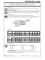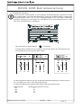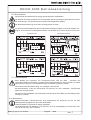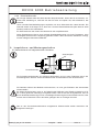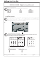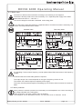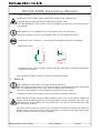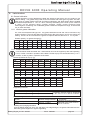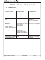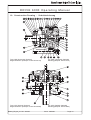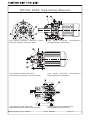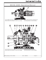
1
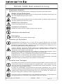
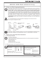
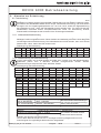
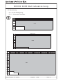
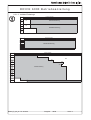
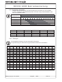
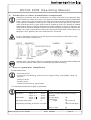
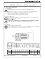
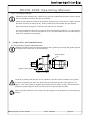
DRIVE 6000
Getriebe und Getriebemotoren
Gear and Gearmotor
Betriebsanleitung
Operating Manual
Nr.
991009
08/2006
DRIVE 6000 Betriebsanleitung
Copyright 2006
Alle Rechte vorbehalten
Nachdruck, auch auszugsweise, ist nur mit ausdrücklicher Genehmigung von Sumitomo Drive
Technologies gestattet.
Die Angaben in dieser Einbau- und Betriebsanleitung wurden mit grösster Sorgfalt auf ihre Richtigkeit
geprüft. Trotzdem kann für eventuelle fehlerhafte oder unvollständige Angaben keine Haftung übernommen
werden.
Technische Änderungen vorbehalten.
Inhaltsverzeichnis:
1.
2.
3.
4.
5.
6.
Allgemeine Hinweise . . . . . . . . . . . . . . . . . . . . . . . . . . . . . . .2
Hinweise zur Sicherheit . . . . . . . . . . . . . . . . . . . . . . . . . . . .2
Hinweise zum Transport . . . . . . . . . . . . . . . . . . . . . . . . . . . .2
Anbau von Übertragungselementen . . . . . . . . . . . . . . . . . .3
Einbau des Getriebes/Getriebemotors . . . . . . . . . . . . . . . .3
5.1
Notwendige Hilfsmittel . . . . . . . . . . . . . . . . . . . . . . . . . . . . . .3
5.2
Einbautoleranzen am Getriebe/Getriebemotor . . . . . . . . . . . . .3
5.3
Prüfungen vor Beginn der Installationsarbeiten . . . . . . . . . . . .4
5.4
Vorbereitende Arbeiten . . . . . . . . . . . . . . . . . . . . . . . . . . . . .4
5.5
Aufstellung . . . . . . . . . . . . . . . . . . . . . . . . . . . . . . . . . . . . . .4
Elektrische Installation . . . . . . . . . . . . . . . . . . . . . . . . . . . . .4
6.1
Sicherheitshinweise . . . . . . . . . . . . . . . . . . . . . . . . . . . . . . . .4
6.2
Einsatzbereich . . . . . . . . . . . . . . . . . . . . . . . . . . . . . . . . . . .5
6.3
Aufstellung . . . . . . . . . . . . . . . . . . . . . . . . . . . . . . . . . . . . . .5
6.4
Kabeleinführungen . . . . . . . . . . . . . . . . . . . . . . . . . . . . . . . . . . .5
6.5
Elektrischer Anschluss . . . . . . . . . . . . . . . . . . . . . . . . . . . . . .6
6.6
Bremsmotoren . . . . . . . . . . . . . . . . . . . . . . . . . . . . . . . . . . .7
6.7
Umrichterbetrieb . . . . . . . . . . . . . . . . . . . . . . . . . . . . . . . . . .7
6.8
6.9
7.
8.
9.
10.
11.
12.
Motorschutz . . . . . . . . . . . . . . . . . . . . . . . . . . . . . . . . . . . . .7
Fremdlüfter . . . . . . . . . . . . . . . . . . . . . . . . . . . . . . . . . . . . . .8
Inbetriebnahme des Antriebs . . . . . . . . . . . . . . . . . . . . . . . .8
Hinweise zur Schmierung . . . . . . . . . . . . . . . . . . . . . . . . . . .9
8.1
Fettschmierung . . . . . . . . . . . . . . . . . . . . . . . . . . . . . . . . . . .9
8.1.1
Lebensdauerfettschmierung . . . . . . . . . . . . . . . . . . . . . . . . . .9
8.1.2
Fettschmierung mit Nachschmierung . . . . . . . . . . . . . . . . . . .9
8.2
Ölschmierung . . . . . . . . . . . . . . . . . . . . . . . . . . . . . . . . . . .10
8.2.1
Art der Ölschmierung . . . . . . . . . . . . . . . . . . . . . . . . . . . . .10
8.2.1.1 Horizontale Einbaulage . . . . . . . . . . . . . . . . . . . . . . . . . . . .10
8.2.1.2 Vertikale Einbaulage . . . . . . . . . . . . . . . . . . . . . . . . . . . . . .11
8.2.2
Empfohlene Schmieröle . . . . . . . . . . . . . . . . . . . . . . . . . . .12
8.2.3
Ölmengen . . . . . . . . . . . . . . . . . . . . . . . . . . . . . . . . . . . . .12
8.2.4
Ölwechselintervalle . . . . . . . . . . . . . . . . . . . . . . . . . . . . . . .13
Inspektions- und Wartungsarbeiten . . . . . . . . . . . . . . . . .13
9.1
Nachschmieren bei fettgeschmierten Getrieben . . . . . . . . . . .13
9.2
Ölstandprüfen . . . . . . . . . . . . . . . . . . . . . . . . . . . . . . . . . . .14
9.3
Öl überprüfen . . . . . . . . . . . . . . . . . . . . . . . . . . . . . . . . . . .14
9.4
Öl wechseln . . . . . . . . . . . . . . . . . . . . . . . . . . . . . . . . . . . .14
Hinweise zu Betriebsstörungen . . . . . . . . . . . . . . . . . . . . .15
Schnittzeichnungen . . . . . . . . . . . . . . . . . . . . . . . . . . . . . . .33
Ersatzteile Liste . . . . . . . . . . . . . . . . . . . . . . . . . . . . . . . . . .37
D6000_D_08_06 Nr. 991009
Ausgabe:
08/06
Seite
1
DRIVE 6000 Betriebsanleitung
1. Allgemeine Hinweise
Bitte beachten Sie in dieser Dokumentation unbedingt die folgenden Sicherheitshinweise!
Gefahr durch Elektrizität
Eine falsche Anwendung der Maschine kann zu Körperschäden, ernsthaften Verletzungen und/
oder lebensgefährlichen Situationen führen.
Gefahr
Eine falsche Anwendung der Maschine kann zu Körperschäden, ernsthaften Verletzungen und/
oder lebensgefährlichen Situationen führen.
Gefährliche Situation
Leichte Verletzungen können die Folge sein.
Schädliche Situation
Schäden am Antrieb oder der Umgebung können die Folge sein.
Hilfreiche Informationen
Entsorgung
Bitte achten Sie auf die geltenden Bestimmungen
2. Hinweise zur Sicherheit
Lesen Sie vor der Arbeit mit der Maschine (Montage, Betrieb, Wartung, Inspektion, usw.) diese
Betriebsanleitung aufmerksam durch, so dass Sie eine genaue Kenntnis über die richtige
Bedienung des CYCLO DRIVE, die anzuwendenden Sicherheitsbestimmungen und die zu
beachtenden Warnhinweise haben. Bewahren Sie diese Anleitung bei der Maschine auf, so
dass Sie bei Bedarf jederzeit nachschlagen können.
Transport, Montage, Schmierung, Betrieb, Wartung und Inspektion dürfen nur durch ausgebildetes technisches Fachpersonal durchgeführt werden; andernfalls besteht die Gefahr von
Verletzungen oder Schäden an der Maschine.
Niemals in sich bewegende Teile fassen und Fremdkörper von diesen Teilen fernhalten; andernfalls besteht die Gefahr von Verletzungen oder Schäden an der Maschine.
Die Anlage darf nur für den vorgesehenen Verwendungszweck eingesetzt werden; andernfalls
besteht die Gefahr von Verletzungen oder Schäden an der Maschine.
Die Anlage darf nur für den vorgesehenen Verwendungszweck eingesetzt werden; andernfalls
besteht die Gefahr von Verletzungen oder Schäden an der Maschine.
3 . H i n w e i s e z u m Tr a n s p o r t
Die Lieferung muss sofort nach Erhalt auf etwaige Transportschäden untersucht werden. Ggf.
müssen diese sofort dem Transportunternehmen mitgeteilt werden. Wenn angenommen werden muss, dass ein Transportschaden den ordnungsgemäßen Betrieb einschränkt, muss die
Inbetriebnahme ausgeschlossen werden.
Es dürfen nur zweckmäßige und ausreichend dimensionierte Seilschlingen, die in die ggf.
vorhandenen Ringschrauben eingehängt oder um die Flanschverbindungen gelegt werden, verwendet werden. Eingeschraubte Ringschrauben sind nur für das Gewicht des Antriebs ausgelegt. Es dürfen keine zusätzlichen Lasten angehängt werden.
Generell gilt: Nicht die Zentrierbohrungen an den Wellenenden benutzen, um das Getriebe mittels Ringschrauben etc. aufzuheben. Lagerschäden können die Folge sein.
D6000_D_08_06 Nr. 991009
Ausgabe:
08/06
Seite
2
DRIVE 6000 Betriebsanleitung
4. Anbau von Übertragungselementen
Die Montage erfolgt mit Hilfe der Zentrierbohrungen an den Wellenenden oder durch Anwärmen
der aufzuziehenden Teile auf maximal 100° C. Die Wellen sind mit einer Nut für Paßfedern nach
DIN 6885, Blatt 1, versehen. Die Bohrungen von Teilen, die auf die Getriebewelle aufgesteckt
werden, sollen mit den im jeweiligen Produktkatalog empfohlenen Toleranzen gefertigt werden.
Zur Sicherung gegen axiales Verschieben ist eine Stellschraube oder ähnliches anzubringen.
Um die Radiallasten gering zu halten, müssen Kettenräder, Scheiben oder Zahnräder so nahe
wie möglich an das Lager gesetzt werden (s. Bild unten). Wenn die Drehmomentübertragung
über Ritzel, Kette etc. erfolgt, muss der Antrieb so eingebaut werden, dass das
Getriebegehäuse auf das Fundament gedrückt wird. Bei Getrieben mit Hohl-Antriebswelle ist
auf die Motorwelle MoS2-Paste oder Spray (z.B. Molykote) aufzutragen, bevor das Gegenstück
angebaut wird.
An- und Abtriebselemente wie Riemenscheiben, Kupplungen usw. müssen mit einem
Berührungsschutz abgedeckt werden !
Kupplungen, Scheiben, Zahnräder, Ketten usw., die auf die Getriebewellen aufgesetzt werden,
dürfen weder aufgepreßt noch aufgeschlagen werden, um Lagerschäden zu vermeiden.
5. Einbau des Getriebes/Getriebemotors
5.1 Notwendige Hilfsmittel
- Schraubenschlüsselsatz
- Drehmomentschlüssel für Befestigungsschrauben an Fuss-/Flanschgehäuse, Motorlaterne,
Klemmkupplungen usw.
- Aufziehvorrichtung
- Ausgleichselemente
- Korrosionschutz (z.B. MoS2-Paste)
5.2 Einbautoleranzen am Getriebe/Getriebemotor
Wellen
Antriebwellen
k6 für
h6 für
Abtriebwellen
k6 für
h6 für
Hohlwelle im Antrieb F7
Zentrierbohrungen nach DIN
D6000_D_08_06 Nr. 991009
Flansche
∅<
∅>
∅<
∅>
30
30
50
50
mm
mm
mm
mm
Zentrierrandtoleranz nach DIN 42948
IEC-Flansch antriebseitig H8
Flansch abtriebseitig
j6
bis Baugrösse 612
f8
ab Baugrösse 613
Gehäuse bei F-Type
g6
332, Form DR
Ausgabe:
08/06
Seite
3
DRIVE 6000 Betriebsanleitung
5.3 Prüfungen vor Beginn der Installationsarbeiten
- Übereinstimmung der Angaben auf dem Typenschild mit den vorliegenden Dokumentationen
(Zeichnungen, Stücklisten, usw.)
- Übereinstimmung der Leistungsdaten des eventuell vorhandenen Motors mit dem elektrischen Versorgungsnetz
- Der Antrieb darf keine Beschädigungen aufweisen
- Die vorgesehenen Schmierstoffe müssen entsprechend der Umgebungsbedingungen passen
und ggf. bereitgestellt werden
5.4 Vorbereitende Arbeiten
Der für Transport und Lagerung verwendete Korrosionsschutz (Marke Valvoline Tectyl 846/K19)
an den Wellenenden oder Hohlwellen und an den Zentriersitzen muss vor der Inbetriebnahme
entfernt werden. Der Korrosionsschutz kann mit einem alkalischen Reiniger entfernt werden, auf
keinen Fall jedoch mechanisch (Schleifmittel etc.). Das alkalische Lösungsmittel darf nicht mit
Dichtungen in Berührung kommen.
Beim Umgang mit Schmierstoffen und Korrosionsschutzmitteln sind die Schutzvorschriften für
Mensch und Umwelt gemäß den entsprechenden Sicherheitsdatenblättern nach DIN 52 900 zu
beachten.
5.5 Aufstellung
Der Antrieb ist so aufzustellen, dass er für eventuelle Nachschmierungen leicht zugänglich ist.
Erst nach sorgfältiger Herstellung einer einwandfreien ebenen, verwindungssteifen und
schwingungsdämpfenden Unterlage für die gesamte Anbaufläche und nach Ausrichtung des
Antriebs sind die Befestigungsschrauben fest anzuziehen. Nach ca. 4 Wochen müssen alle
Befestigungsschrauben auf das richtige Anzugsmoment überprüft werden.
Wenn der Antrieb bis zum max. Abtriebsdrehmoment bzw. der max. Querkraft belastet wird, sind
neben der Fußbefestigung durch Schrauben der Festigkeitsklasse 8.8 oder höher, zusätzliche
formschlüssige Verbindungen (z.B. Zylinderstifte DIN 6325) vorzusehen.
Antriebe, die im Freien oder unter sehr ungünstigen Umgebungsbedingungen, z.B. Schmutz,
Staub, Spritzwasser oder Hitze aufgestellt werden, müssen durch eine Verkleidung geschützt
werden. Dabei darf die freie Luftzufuhr an der Gehäuseoberfläche nicht beeinträchtigt werden.
Ölkontroll- und Ablassschrauben sowie Atmungsfilter müssen frei zugänglich sein.
Bei Gefahr von elektrochemischer Korrosion zwischen Getriebe und Arbeitsmaschine
(Verbindung unterschiedlicher Metalle wie z. B. Gusseisen/Edelstahl) Zwischeneinlagen aus
Kunststoff verwenden (2-3 mm dick). Schrauben ebenfalls mit Unterlegscheiben aus Kunststoff
versehen. Gehäuse zusätzlich erden - Erdungsschrauben am Motor verwenden.
Für den Einsatz in Feuchträumen oder im Freien werden Antriebe in korrosionshemmender
Ausführung geliefert. Eventuell aufgetretene Lackschäden (z. B. am Entlüftungsventil) müssen
nachgebessert werden.
Wird der Antrieb überlackiert bzw. teilweise nachlackiert, so ist darauf zu achten, dass das
Entlüftungsventil und die Wellendichtringe sorgfältig abgeklebt werden. Nach Beenden der
Lackierarbeiten sind die Klebestreifen zu entfernen.
6 . E l e k t r i s c h e I n s ta l l a t i o n
6.1 Sicherheitshinweise
Montage, Anschluss und Inbetriebnahme sowie Wartungs- und Reparaturarbeiten dürfen nur
durch qualifiziertes Fachpersonal erfolgen.
Vor Beginn jeder Arbeit am Motor oder Getriebemotor, besonders aber vor dem Öffnen von
Abdeckungen aktiver Teile, muss der Motor vorschriftsmäßig freigeschaltet sein.
Die 5 Sicherheitsregeln nach DIN VDE 0105 sind zu beachten.
Diese Elektromotoren entsprechen den gültigen Normen und Vorschriften und erfüllen die
Forderungen der Niederspannungsrichtlinie 73/23/EWG.
D6000_D_08_06 Nr. 991009
Ausgabe:
08/06
Seite
4
DRIVE 6000 Betriebsanleitung
6.2 Einsatzbereich
Die Motoren sind völlig verschlossen und luftgekühlt. Standardschutzart:IP 55 mit Bremse IP 44.
Umgebungstemperatur: -10° . . . +40°C
Aufstellungshöhe: < 1000 m
Die Wicklung ist in Isolationsklasse F (150°C) ausgeführt. Bei bestimmungsgemäßem Betrieb
können an der Motoroberfläche Temperaturen von über 100°C auftreten. Eine Berührung muss
verhindert werden. Temperatur empfindliche Teile dürfen nicht befestigt werden oder anliegen.
6.3 Aufstellung
Die Lüftungsöffnungen in der Lüfterhaube dürfen nicht verschlossen werden.
Für eine ausreichende Kühlung darf der Abstand der Haube zur Wand das Maß FB nicht unterschreiten. FA ist der Mindestabstand, der zur Demontage der Lüfterhaube erforderlich ist.
FA oder FB
Standard Motor
Motor-baugröße:
63 - 71
80
90
100 112-132S 132M-160M
160L
180M 180L
220
FB (mm):
20
20
20
20
20
25
30
30
30
30
FA (mm):
48
49
52
56
60
75
130
155
170
230
63 - 71
80
90 100
160L
180M
180L
220
FB (mm):
20
20
20
20
25
25
30
30
30
30
FA (mm):
61
93
115
121
132
170
220
367
370
445
Bremsmotor
Motor-baugröße:
112-132S 132M-160M
6.4 Kabeleinführungen
Die Motoren der F-Serie können mit folgenden Kabeleinführungen bestückt werden.
Motor-Baugröße
Pg
Metrisch
063 - 132 S
2 x Pg 16
2 x M 25 x 1,5
132M - 160
2 x Pg 21
2 x M 32 x 1,5
180 - 200
2 x Pg 42
2 x M 50 x 1,5
Kabelverschraubungen müssen mindestens der auf dem Typenschild angegebenen
Motorschutzart genügen.
Unbenutzte Kabeleinführungen müssen entsprechend der Motorschutzart verschlossen werden.
Vorhandene Stopfen müssen fest angezogen sein.
D6000_D_08_06 Nr. 991009
Ausgabe:
08/06
Seite
5
DRIVE 6000 Betriebsanleitung
6.5 Elektrischer Anschluss
Technische Daten sowie Angaben zu den zulässigen Einsatzbedingungen entnehmen Sie bitte
dem Leistungsschild und dieser Betriebsanleitung, sowie dem aktuellen Katalog. Angaben über
Sonderauführungen finden Sie auf Ihrer Auftragsbestätigung. Bei eventuellen Unklarheiten
empfehlen wir dringend, unter Angabe der Typenbezeichnung und der Seriennummer im Werk
oder Ihrem Vertriebszentrum rückzufragen.
Den Schutzleiter an dieser Klemme
anschließen.
Im Klemmkasten befindet sich ein Schaltbild. Die Motoren können am Klemmbrett je nach
Anschlussspannung wie folgt geschaltet werden:
Für die angegebenen Spannungen gilt der Bemessungsspannungsbereich nach EN 60 034-1
mit ± 5% Spannungs- oder ± 2% Frequenzabweichung.
Für die Gewindebolzen des Klemmbrettes gelten folgende Anzugsmomente:
Bolzengewinde:
M4
M5
M6
M8
D6000_D_08_06 Nr. 991009
zulässiges Anzugsmoment in Nm
1,2
2,5
4,0
7,5
Ausgabe:
08/06
Seite
6
DRIVE 6000 Betriebsanleitung
6.6 Bremsmotoren
Der Anschluß der Bremsmotoren erfolgt gemäß folgenden Schaltbildern.
Die Bremse ist bereits verdrahtet. Für eine separate Spannungsversorgung der Bremse müssen
die Verbindungen vom Klemmbrett zum Gleichrichter abgeklemmt werden.
Die Bremssteuerspannung ist auf dem Leistungsschild vermerkt.
Für eine schnelle Einfallzeit der Bremse (gleichstromseitiges Schalten) muss eine separate Leitung zu einem externen Kontakt geführt werden. Der Kontakt ist mit einem Varistor zu schützen.
Schnellwirkende Bremse
Standard Bremse
6.7 Umrichterbetrieb
Beim Betrieb der F-Motoren am Frequenzumrichter sind die EMV - Hinweise des
Umrichterherstellers zu beachten. Entsprechende Entstörmaßnahmen sind zu treffen. Es sollten
abgeschirmte Leitungen und Kabeleinführungen aus Metall vorgesehen werden.
Das Drehmoment des Motors hängt vom jeweiligen Umrichter ab.
Bei Bremsmotoren muss der Gleichrichter der Bremse mit einer separaten, sinusförmigen
Spannung versorgt werden.
Der Motor ist durch Kaltleiter, Thermokontakte und/ oder durch Fremdlüfter vor übermäßiger Überhitzung zu schützen.
6.8 Motorschutz
Motorschutzschalter (Überstromschutz) sind entsprechend der Spannung auf den auf dem
Leistungsschild angegebenen Stromwert einzustellen.
Thermokontakte sind generell als Öffner ausgeführt .
Der Widerstandwert von Kaltleitern (PTC) bei 20°C ist nicht aussagekräftig. Der Wert kann zwischen 90 Ω und max. 750 Ω variieren.
D6000_D_08_06 Nr. 991009
Ausgabe:
08/06
Seite
7
DRIVE 6000 Betriebsanleitung
6.9 Fremdlüfter
Der Anschluss der Fremdlüfter erfolgt im Klemmenkasten auf der Fremdlüfterhaube.
Der Fremdlüftermotor sollte eine separate Spannungsversorung erhalten.
ACHTUNG: Je nach Steuerung kann der Fremdlüfter in Betrieb sein, auch wenn der Motor nicht
dreht.
Leistungsschilder und Anschlussbilder zu dem Fremdlüfter befinden sich im Klemmenkasten.
Baugrößenabhängig sind diese unterschiedlich ausgeführt. Der Lüftermotor kann wie folgt ausgeführt sein:
- Spaltpolmotor: Anschluss, L1 und N (Drehrichtungsumkehr nicht möglich)
- Kondensatormotor:
L1
N
U1
Z1
U1
Z2
U2
Z2
L1
Linkslauf
N
Z1
U2
Rechtslauf
- Drehstrommotor: In Stern- oder Dreieckschaltung, ja nach Spannung wie im Kapitel "Elektrischer
Anschluss".
- Drehrichtungsumkehr durch vertauschen zweier Phasen.
7. Inbetriebnahme des Antriebs
Auf die genaue Beachtung der Sicherheitshinweise wird nochmals ausdrücklich hingewiesen.
Netzverhältnisse und Leistungsschildangaben müssen übereinstimmen. Für Zusatzeinrichtungen,
z.B. Stillstandsheizungen, sind zusätzliche Angaben im Motorklemmenkasten.
Anschlusskabel sind im Querschnitt den Motorströmen anzupassen.
Die Installation muss unter Beachtung der gültigen Vorschriften von entsprechend geschultem
Fachpersonal erfolgen.
Vor dem Einschalten des Getriebemotors ist zu überprüfen, dass alle Sicherheitsbestimmungen
eingehalten werden, die Maschine ordnungsgemäß montiert und ausgerichtet ist, alle
Befestigungsteile und Erdungsanschlüsse fest angezogen sind, die Hilfs- und
Zusatzeinrichtungen funktionsfähig und ordnungsgemäß angeschlossen sind und die Paßfeder
eines eventuell vorhandenen zweiten Wellenendes gegen Wegschleudern gesichert ist.
Der Getriebemotor ist, falls möglich, ohne Last einzuschalten. Läuft er ruhig und ohne abnormale
Geräusche, wird der Motor mit der Arbeitsmaschine belastet. Bei der Inbetriebnahme empfiehlt
sich eine Beobachtung der aufgenommenen Ströme, wenn der Motor mit seiner Arbeitsmaschine
belastet ist, damit mögliche Überlastungen und netzseitige Asymmetrien sofort erkennbar sind.
D6000_D_08_06 Nr. 991009
Ausgabe:
08/06
Seite 8
DRIVE 6000 Betriebsanleitung
8. Hinweise zur Schmierung
8.1 Fettschmierung
Fettgeschmierte CYCLO Drive 6000 sind bereits ab Werk mit Fett gefüllt und werden ohne
Nachfüllung in Betrieb gesetzt. Die eingefüllte Fettsorte darf nicht mit anderen Fettsorten gemischt werden. Die Standardfette ESSO Unirex N2 (für Lebensdauerschmierung) und Shell Alvania
R2 eignen sich für Umgebungstemperaturen von -10°C bis +50°C, wobei eine Eigenerwärmung
des Getriebes bis max. +60°C bei Dauerbetrieb erreicht werden kann. Für einen Einsatz der
Standardfette außerhalb dieses Temperaturbereiches sowie die Verwendung anderer
Schmierstoffe ist Rücksprache bei Sumitomo Drive Technologies erforderlich.
8.1.1 Lebensdauerfettschmierung
Alle CYCLO Drive 6000 Typ CN.. haben eine Lebensdauerfettschmierung und können in jeder
beliebigen Position eingebaut werden. Diese Getriebe sind werkseitig mit ESSO Unirex N2 gefüllt
und benötigen keine Nachschmierung. Die Lebensdauer kann erhöht werden, wenn nach 20.000
Stunden oder 4 bis 5 Jahren das Fett erneuert wird.
Fettmengen (g) bei Erneuerung
Grösse 606
1. Stufe 25
607
25
608
65
609
90
610
140
611
200
612
330
35
70
100
100
90
120
606DA 607DA 609DA 610DA 612DA 612DB
25
25
25
25
25
90
2.Stufe
Abtrieb
35
25
25
90
140
330
330
35
35
100
100
120
120
8.1.2 Fettschmierung mit Nachschmierung
CYCLO Drive 6000, die mit Shell Alvania R2 gefüllt sind, müssen nach 500 Betriebsstunden,
spätestens jedoch nach 2 Monaten, erstmals nachgeschmiert werden. Weitere
Nachschmierungen entsprechend unten stehender Tabelle:
Fettmengen (g) bei Nachschmierung
Grösse
1. Stufe
613
25
613DB
90
613DC
140
614DA
25
614DB
90
614DC
140
616DA
90
616DB
140
617DA
90
617DB
140
2.Stufe
450
450
450
450
450
450
750
750
1000
1000
Abtrieb
300
300
300
300
300
300
300
300
500
500
Grösse
1. Stufe
618DA
100
618DB
450
619DA
150
619DB
450
620DA
150
620DB
450
621DA
450
621DB
750
622DA
450
622DB
1000
2. Stufe
1100
1100
1500
1500
1500
1500
2000
2000
2500
2500
Abtrieb
600
600
700
700
700
700
800
800
900
900
Grösse
1. Stufe
623DA
750
623DB
1100
624DA
750
624DB
1100
625DA
1000
625DB
1500
626DA
1500
2. Stufe
4000
4000
4500
4500
6000
6000
8000
Abtrieb
1000
1000
1100
1100
1200
1200
1300
Nachschmierungsfristen
Einsatzbedingungen
bis 10 Stunden/Tag
10 - 24 Stunden/Tag
Zeitpunkt zur Nachschmierung
alle 3 - 6 Monate
alle 500 - 1000 Stunden
Anmerkungen
Bei erschwerten Betriebsbedingungen müssen die Nachschmierungsfristen verkürzt werden
Fristen für den Fettwechsel
Bereich
Antrieb und Übersetzung
Abtrieb
Zeitpunkt des Fettwechsels
Anmerkungen
Bei
erschwerten Betriebsbedingunalle 2 - 3 Jahre
gen müssen die Fristen für den
alle 3 - 5 Jahre
Fettwechsel verkürzt werden
Einfüllen und Wechsel von Schmierstoffen:
CYCLO Drive 6000 ab Größe 613 sind in 2-stufiger Ausführung fettgeschmiert und mit
Schmiernippeln für regelmäßiges Nachschmieren ausgestattet.
D6000_D_08_06 Nr. 991009
Ausgabe:
08/06
Seite 9
DRIVE 6000 Betriebsanleitung
8.2 Ölschmierung
8.2.1 Art der Ölschmierung
8.2.1.1 Horizontale Einbaulage
Größe
3
5
6
8
11
13
15
einstufige Einheiten
17
21
25
29
35
43
51
59
71
87
613
614
Ölbad
616
617
618
619
Größe
11
15
21
Einstufige Einheiten
29
35
43
59
87
620
621
622
Ölbad
623
624
625
626
627
Größe
zweistufige Einheiten
104 121 143 165 195 231 319 357 377 425 473 525 559 649 731 841 1003 1015 1247 1479 1894 2065 2537 3045 3481 4437 5133 6177 7569
616DC
617DC
618DB
619DA
619DB
620DA
620DB
621DA
621DB
622DA
622DB
623DA
623DB
624DA
624DB
625DA
625DB
Ölbad
626DA
627DA
D6000_D_08_06 Nr. 991009
Ausgabe:
08/06
Seite 10
DRIVE 6000 Betriebsanleitung
8.2.1.2 Vertikale Einbaulage
Größe
613
3
5
6
8
11
13
15
Einstufige Einheiten
17
21
25
29
35
43
51
59
71
87
Öltauchschmierung
Fett
614
616
Fett
617
Ölumlaufschmierung
618
619
Größe
11
15
21
620
621
622
623
624
625
626
627
Größe
616DC
Einstufige Einheiten
29
35
43
59
87
Ölumlaufschmierung
mit Trochoidenpumpe
zweitufige Einheiten
104 121 143 165 195 231 319 357 377 425 473 525 559 649 731 841 1003 1015 1247 1479 1894 2065 2537 3045 3481 4437 5133 6177 7569
473
841
617DC
Fett
1015
618DB
619DA
619DB
620DA
620DB
621DA
621DB
622DA
622DB
623DA
623DB
624DA
624DB
625DA
625DB
2065
1849
2537
Ölumlaufschmierung
626DA
627DA
D6000_D_08_06 Nr. 991009
mit Trochoiden Pumpe
Ausgabe:
08/06
Seite 11
DRIVE 6000 Betriebsanleitung
8.2.2 Empfohlene Schmieröle
Geeignet sind alle Schmieröle, die die Anforderungen nach DIN 51517 Teil 3 erfüllen.
Je nach Umgebungs- oder Betriebstemperatur muss die richtige Viskositätsklasse nach
DIN 51519 gewählt werden.
Schmierstoff nach
DIN 57517 Teil 3
-20°C
mögliche Betriebstemperaturen °C
Umgebung
0°C
+20°C +40°C +60°C +80°C
+100°C
CLP 68
CLP 100
CLP 150
CLP 220
CLP 320
Hersteller
Marke
ARAL
Degol BG
AVIA
Gear RSX
BP
Energol GR-XP
Castrol
Alpha MW
Hersteller
DEA
ELF
ESSO
KLÜBER
Marke
Falcon CLP
Reductelf SP
Spartan EP
Klüberoil GEM 1
Hersteller
MOBIL
OPTIMOL
SHELL
TOTAL
Marke
Mobilgear
Ultra
Omala
Carter EP
8.2.3 Ölmengen
Die angegebenen Mengen sind durchschnittliche Richtwerte.
Die genaue Menge ist anhand des vorgeschriebenen Ölstands zu kontrollieren.
CHH.., CHHX.., CHV.., CHVX..
Größe
613
614
616
617
618
619
620
621
622
623
624
625
626
[l]
0,7
0,7
1,4
1,9
2,5
4,0
5,5
8,5
10
15
16
21
29
627
56
Größe
616DC
617DC
618DA
618DB
619DA
619DB
620DA
620DB
621DA
621DB
622DA
622DB
623DA
623DB
6,0
6,0
10
10
11
11
17
17
627
[l]
1,5
2,4
3,5
3,5
5,8
6,0
Größe
624DA
624DB
625DA
625DB
626DA
627DA
[l]
18
18
CVV.., CVVX..
23
23
32
70
Größe
613
614
616
617
618
619
620
621
622
623
624
625
626
[l]
1,1
1,1
1,0
1,9
2,0
2,7
5,7
7,5
10
12
15
42
51
60
Größe
616DC
617DC
618DA
618DB
619DA
619DB
620DA
620DB
621DA
621DB
622DA
622DB
623DA
623DB
11
11
14
14
18
18
23
23
620
621
622
623
624
625
626
627
[l]
1,0
1,9
2,0
2,0
2,7
2,7
Größe
624DA
624DB
625DA
625DB
626DA
627DA
[l]
29
42
42
51
60
Größe
613
616
617
618
619
29
CHF.., CHFX..
614
[l]
0,25
0,25
0,9
1,5
1,3
2
3
4
5
7,5
8
11
14
30
Größe
616DC
617DC
618DA
618DB
619DA
619DB
620DA
620DB
621DA
621DB
622DA
622DB
623DA
623DB
4,0
4,0
5,5
5,5
6,0
6,0
9,5
9,5
[l]
1,0
2,0
2,3
2,3
3,8
4,0
Größe
624DA
624DB
625DA
625DB
626DA
627DA
[l]
10
10
13
13
17
44
D6000_D_08_06 Nr. 991009
Ausgabe:
08/06
Seite 12
DRIVE 6000 Betriebsanleitung
8.2.4 Ölwechselintervalle
Der richtige Ölstand sollte alle 5000 Stunden überprüft werden. Wenn das Öl verschmutzt, verbrannt oder zähflüssig ist, wechseln Sie das Öl sofort und spülen Sie, falls erforderlich, das
Getriebe.
Unter normalen Betriebsbedingungen empfehlen wir einen Ölwechsel alle 10000 Stunden. Die
Intervalle sollten nicht länger als 2 Jahre sein. Kürzere Ölwechselintervalle (alle 3000 bis 5000
Stunden) erhöhen die Lebensdauer
Ein Ölwechsel nach den ersten 500 Stunden ist sehr empfehlenswert..
Obige Empfehlungen können unter anderen Betriebsbedingungen wie hohe Temperatur, hohe
Feuchtigkeit oder korrosive Umgebung geändert werden. Wenn eine dieser Situationen vorliegt,
müssen häufigere Ölwechsel stattfinden.
9 . I n s p e k t i o n s - u n d Wa r t u n g s a r b e i t e n
9.1 Nachschmieren bei fettgeschmierten Getrieben
Schmiernippel
Kontrollschraube
Die Schmierkontrollschraube am Gehäuse abschrauben und mit einer Fettpresse durch den
Schmiernippel am Flansch auf der Antriebseite oder am Motorflansch Fett nachschmieren.
Die Getriebe während des Betriebs nachschmieren, um eine gute Zirkulation des Schmierfetts
sicherzustellen.
Bei jedem Nachschmieren muss ca. ein Drittel bis die Hälfte der in der Tabelle in Kapitel 8.1.2 für
die 1. Stufe genannten Fettmenge nachgefüllt werden. Falls zuviel Fett nachgefüllt wird, kann es
durch die Betriebserwärmung zu einer unzulässigen Erwärmung des Schmierstoffs kommen, oder
es kann durch Überdruck Fett in den Motor gelangen oder zu Leckagen kommen.
Das an den Schmierkontrollschrauben ausgetretene Überschussfett sauber abwischen und
fachgerecht entsorgen.
D6000_D_08_06 Nr. 991009
Ausgabe:
08/06
Seite 13
DRIVE 6000 Betriebsanleitung
9.2 Ölstand prüfen
Der Ölstand kann an der Ölstandsanzeige überprüft werden
Bei horizontal eingebauten Getrieben befindet sich die Ölstandsanzeige normalerweise auf der
rechten Seite des Getriebes von der Abtriebwelle aus gesehen. Da die Ölstandsanzeige sowohl
links oder rechts angebracht werden kann, ist die für das Ablesen günstigere Seite zu wählen.
Während des Betriebs gilt die untere Markierung auf der Ölstandsanzeige als Richtwert für den
normalen Ölstand. Unmittelbar nach der Inbetriebnahme kann der Ölstand unter die untere rote
Markierung fallen. Dies ist jedoch nicht weiter von Bedeutung, da der Ölstand wieder ansteigt,
wenn die Ölviskosität aufgrund der Betriebserwärmung abnimmt.
9.3 Öl überprüfen
· Getriebemotor spannungslos schalten, gegen unbeabsichtigtes Wiedereinschalten sichern.
· Abwarten, bis Getriebe abgekühlt ist - Verbrennungsgefahr!
· An Ölablassschraube etwas Öl entnehmen.
· Ölbeschaffenheit überprüfen.
· Viskosität überprüfen.
· Zeigt das Öl visuell starke Verschmutzung wird empfohlen, außerhalb der unter Kapitel 8.2.4
"Ölwechselintervalle" vorgegebenen Wartungsintervalle das Öl zu wechseln.
· Die entnommene Ölprobe ist fachgerecht zu entsorgen.
9.4 Öl wechseln
· Getriebemotor spannungslos schalten, gegen unbeabsichtigtes Wiedereinschalten sichern.
· Abwarten, bis Getriebe abgekühlt ist - Verbrennungsgefahr!
·
·
·
·
·
·
Ölwechsel nur bei betriebswarmem Getriebe durchführen.
Gefäß unter Ölablassschraube stellen.
Ölstandsanzeige, Entlüftungsschraube/-ventil und Ölablassschraube entfernen.
Öl vollständig ablassen.
Ölablassschraube eindrehen.
Neues Öl entsprechend der Ölempfehlung über die Öleinfüllschraube einfüllen. Vor
Verwendung anderer Ölsorten Rücksprache mit Sumitomo Drive Technologies.
· Ölmenge entsprechend Kapitel 8.2.3 "Ölmengen" einfüllen.
· An der Ölstandsanzeige überprüfen.
· Entlüftungsschraube/-ventil eindrehen.
· Das abgelassene Öl ist fachgerecht zu entsorgen.
D6000_D_08_06 Nr. 991009
Ausgabe:
08/06
Seite 14
D6000_D_08_06 Nr. 991009
Ausgabe:
08/06
Seite 15
1)
1. Schrauben am Getriebedeckel nachziehen und
Getriebe beobachten. Tritt weiter Öl aus:
Kundendienst anrufen
2. Kundendienst anrufen
3. Getriebe entlüften (siehe Bauformen)
Öl überprüfen (siehe Inspektions- und
Wartungsarbeiten)
Antrieb stillsetzen, Kundendienst anrufen
1. Öl überprüfen (siehe Inspektions- und
Wartungsarbeiten), Lager wechseln
2. Kundendienst anrufen
Fehlerbehebung
Wellen-Nabenverbindung im Getriebe unterbrochen
Getriebe/Getriebemotor zur Reparatur einschicken
- zu viel Öl
Ölmenge korrigieren (siehe Ölstand überprüfen).
Entflüftungsventil korrekt anbringen und Ölstand
- Antrieb in der falschen Bauform eingesetzt
korrigieren (siehe Ölstand überprüfen).
- häufiger Kaltstart (Öl schäumt) und / oder hoher
Ölstand
3. Getriebe nicht entlüftet
2. Dichtung defekt
1. Dichtung im Getriebedeckel undicht
Fremdkörper im Öl
1. Geräusch abrollend/mahlend: Lagerschaden
2. Geräusch klopfend: Unregelmäßigkeit in der
Übersetzung
mögliche Ursache
Am Wellendichtring in geringen Mengen austretendes Öl/Fett ist in der Einlaufphase (24 Stunden Laufzeit) als normal
anzusehen (siehe auch DIN 3761).
Abtriebwelle dreht nicht, obwohl Motor
läuft oder Antriebswelle gedreht wird
Öl tritt aus am Entlüftungsventil
Öl tritt aus 1)
- am Getriebedeckel
- am Motorflansch
- am Motorwellendichtring
- am Getriebeflansch
- am abtriebsseitigen Wellendichtring
ungewöhnliche, ungleichmäßige
Laufgeräusche
ungewöhnliche, gleichmäßige
Laufgeräusche
Betriebsstörung
10. Mögliche Betriebsstörungen - Fehlerursachen und Maßnahmen
DRIVE 6000 Betriebsanleitung
Für Ihre Notizen:
DRIVE 6000 Operating Manual
Copyright 2006
All rights reserved
Reproduction in part or whole is not permitted without our prior approval.
Whilst every care has been taken in preparation of this manual, no liability can be accepted for any errors
or omissions.
Subject to technical changes.
Content:
1.
General information . . . . . . . . . . . . . . . . . . . . . . . . . . . . . . . .2
2.
Safety advice . . . . . . . . . . . . . . . . . . . . . . . . . . . . . . . . . . . . .2
3.
Transportation . . . . . . . . . . . . . . . . . . . . . . . . . . . . . . . . . . . .2
4.
Connection of other transmission components . . . . . . . . .3
5.
Gear/gearmotor Installation . . . . . . . . . . . . . . . . . . . . . . . . .3
5.1
Necessary tools . . . . . . . . . . . . . . . . . . . . . . . . . . . . . . . . . .3
5.2
Assembly tolerances . . . . . . . . . . . . . . . . . . . . . . . . . . . . . . .3
5.3
To check before installation . . . . . . . . . . . . . . . . . . . . . . . . . .4
5.4
Getting the unit ready for installation . . . . . . . . . . . . . . . . . . . .4
5.5
Installation of the CYCLO DRIVE . . . . . . . . . . . . . . . . . . . . .4
6.
Electrical connection . . . . . . . . . . . . . . . . . . . . . . . . . . . . . .5
6.1
Safety advise . . . . . . . . . . . . . . . . . . . . . . . . . . . . . . . . . . . .5
6.2
Range of use . . . . . . . . . . . . . . . . . . . . . . . . . . . . . . . . . . . .5
6.3
Installation . . . . . . . . . . . . . . . . . . . . . . . . . . . . . . . . . . . . . .5
6.4
Cable inlet thread sizes . . . . . . . . . . . . . . . . . . . . . . . . . . . . . . . .6
6.5
Electrical connection . . . . . . . . . . . . . . . . . . . . . . . . . . . . . . .6
6.6
Brake motors . . . . . . . . . . . . . . . . . . . . . . . . . . . . . . . . . . . .7
6.7
Installation with frequency inverters . . . . . . . . . . . . . . . . . . . .7
6.8
6.9
7.
8.
9.
10.
11.
12.
Motor protection . . . . . . . . . . . . . . . . . . . . . . . . . . . . . . . . . .7
Forced ventilator . . . . . . . . . . . . . . . . . . . . . . . . . . . . . . . . . .8
Start up . . . . . . . . . . . . . . . . . . . . . . . . . . . . . . . . . . . . . . . . .8
Lubrication . . . . . . . . . . . . . . . . . . . . . . . . . . . . . . . . . . . . . . .9
8.1
Grease lubrication . . . . . . . . . . . . . . . . . . . . . . . . . . . . . . . . .9
8.1.1
Lifetime grease lubrication . . . . . . . . . . . . . . . . . . . . . . . . . . .9
8.1.2
Grease lubrication . . . . . . . . . . . . . . . . . . . . . . . . . . . . . . . . .9
8.2
Oil lubrication . . . . . . . . . . . . . . . . . . . . . . . . . . . . . . . . . . .10
8.2.1
Type of oil lubrication . . . . . . . . . . . . . . . . . . . . . . . . . . . . .10
8.2.1.1 Horizontal mounting . . . . . . . . . . . . . . . . . . . . . . . . . . . . . .10
8.2.1.2 Vertical mounting . . . . . . . . . . . . . . . . . . . . . . . . . . . . . . . .11
8.2.2
Recommended oil type . . . . . . . . . . . . . . . . . . . . . . . . . . . .12
8.2.3
Oil quantity . . . . . . . . . . . . . . . . . . . . . . . . . . . . . . . . . . . . . . . 12
8.2.4
Oil change intervals . . . . . . . . . . . . . . . . . . . . . . . .13
Inspection and maintenance . . . . . . . . . . . . . . . . . . . . . . .13
9.1
Grease refill . . . . . . . . . . . . . . . . . . . . . . . . . . . . . . . . . . . .13
9.2
Oil level check . . . . . . . . . . . . . . . . . . . . . . . . . . . . . . . . . .14
9.3
Oil check . . . . . . . . . . . . . . . . . . . . . . . . . . . . . . . . . . . . . .14
9.4
Oil change . . . . . . . . . . . . . . . . . . . . . . . . . . . . . . . . . . . . .15
Troubleshooting . . . . . . . . . . . . . . . . . . . . . . . . . . . . . . . . . .16
Drawings . . . . . . . . . . . . . . . . . . . . . . . . . . . . . . . . . . . . . . . .33
Spare parts . . . . . . . . . . . . . . . . . . . . . . . . . . . . . . . . . . . . . .37
D6000_GB_08_06 NO. 991009
Issue: 08/2006
page 17
DRIVE 6000 Operating Manual
1. General information
Please observe the following warnings
Electrical hazard
Misapplication of the machine may be dangerous, risk of severe or fatal injury.
Imminent danger
Misapplication of the machine may be dangerous and lead to severe injures.
Dangerous situation
Risk of physical injury
Damaging situation
Risk of machine damage.
H e l pf u l i n f o r m a t i o n
Disposal
Please observe legal /environmental regulations.
2. Safety advice
Do not attempt to install or operate the CYCLO DRIVE until all of these instructions on assembly, operation, maintenance and inspection and hazards are read and thoroughly understood.
Please keep these instructions next to the unit in operation to check at any time when necessary.
Transportation, assembly, lubrication, operation, maintenance and inspection should only be
done by qualified personnel, so as to avoid personal injury or damage to property.
Do not touch moving mechanical components and make sure these parts are clear of obstructions. Failure to follow these instructions may result in personal injury, unit failure or damage to
property.
Only operate the unit in the application it was intended. Misapplication may result in physical
injury or damage to machinery.
3 . Tr a n s p o r ta t i o n r e c o m m e n d a t i o n s
The units must be checked for any transportation damage immediately upon receipt. Any damages should be reported to the carrier without delay. If there is any evidence of damage which
may put at risk the function of the CYCLO DRIVE, do not install the unit.
Lifting harnesses of suitable and adequate size are to be used; these are to be hooked into the
eye bolts or laid round the flange connections. Eye bolts on the gearbox are dimensioned for
the weight of the unit, no additional loads are allowed.
Caution: do not use the central bores in the shaft ends for lifting the drive with hooked bolts,
etc. This could result in damage to the bearings.
D6000_GB_08_06 NO. 991009
Issue: 08/2006
page 18
DRIVE 6000 Operating Manual
4 . C o n n e c t i o n o f o t h e r t r a n s m i s s i o n c o m p o n e n ts
Assembly is carried out using the central bores in the ends of the shaft or by heating the parts
to be mounted to a maximum of 100°C. The shafts have been fitted with keyways to DIN 6885,
sheet 1. Bores of the parts to be fitted on the shafts should be according to the tolerances given
in the respective catalogue. A locking screw or similar is to be used to prevent any axial movement. Chainwheels, discs or gear wheels must be located as close to the bearing as possible
(see illustration below to keep the radial loads as small as possible). If pinions or chains etc. are
used, the drive should be installed so that the unit location fastening act against the applied radial load. In the case of speed reducers with hollow high speed shafts, MoS2 paste or spray (e.g.
Molykote) is to be applied to the motor shaft before it is connected.
It is the responsibility of the user to provide guards for all exposed input and output components such as pulley, couplings, etc.!
Clutches, discs, gear wheels, chains, etc. should be mounted on the reducer shafts carefully. Do
not force them onto the shafts as this could damage the gearbox bearings.
5 . G e a r o r g e a r m o t o r i n s ta l l a t i o n
5.1 Necessary tools
- Screw wrench set
- Torque wrench for fastening screws on foot or flange housing, motor adaptor, clamp coupling, etc.
- Pulling on device
- Mounting shims
- Corrosive protection (e.g. MoS2-Paste)
5.2 Assembly tolerances for gear or gearmotor
Shafts
Input shaft
k6 for
h6 for
Output shaft
k6 for
h6 for
High speed hollow shaft
Centre boring according to
D6000_GB_08_06 NO. 991009
Flanges
∅
∅
∅
∅
<
>
<
>
30 mm
30 mm
50 mm
50 mm
F7
DIN 332, Form DR
Centering shoulder tolerances according to
DIN 42948
IEC-Input flange
H8
Output flange
V type
j6
up to size 612
f8
size 613 and larger
Casing F-Type
g6
Issue: 08/2006
page 19
DRIVE 6000 Operating Manual
5.3 Please check before installation
-
Data on name plate matches with other documents such as drawings, parts list, etc.
In case of gearmotor, check if power is up to the motor requirements
Inspect the gearbox for possible damage.
Provide the recommended lubricants according to the environment of the installation.
5.4 Before starting up
The anti-corrosive agent (Valvoline Tectyl 846/K19) used for transportation and storage on the
shaft-ends or hollow shafts, and on the central seats must be removed before start up. This anticorrosive agent can be removed using an alkaline detergent; under no circumstances is it to be
removed mechanically (abrasive etc.). The alkaline detergent must not come into contact with the
seals.
When handling lubricants and anti-corrosive agents please observe the respective safety instructions for people and environment according to DIN 52 900.
5.5 Installation
The drive should be installed so that it is easily accessible for any future lubrication or grease topup.
First establish a perfect level, using a non-distorting and vibration- absorbing base for the complete mounting area, and align the drive before tightening the fastening screws. Check all fastening screws for correct torque after about 4 weeks. Dowl pins (e.g. DIN 6325 cylinder pins) are to
be used in addition to the base fastening with screws of property class 8.8 or greater if the drive
is being driven to the maximum output torque or maximum radial load.
Units to be installed outdoors or in very unfavourable ambient conditions, e.g. dirt, dust, spray
water or heat, should be protected by covers. Free air access to the housing surface must not be
impaired under these circumstances.
Oil level, drain plug and breathing filter must also be clear for access.
.
In case of electrochemical corrosion risk due to contact of different metals such as cast iron and
fine steel, plastic protection of 2 or 3 mm thick should go between gear and machine. Screws
should also be protected by plastic discs. In addition, protect the housing with earthing screws
fixed to the motor.
Special corrosive protected units are available for installation in wet conditions.
When re-painting the unit, please cover carefully the breather and the shaft seals. Remove any
covering after the painting has been finished.
D6000_GB_08_06 NO. 991009
Issue: 08/2006
page 20
DRIVE 6000 Operating Manual
6 . E l e c t r i c a l i n s ta l l a t i o n
6.1 Safety advice
Installation, start up and servicing should only be done by qualified personnel.
Before commencing upon the servicing of the motor or the gearmotor, particularly before
opening covers to active parts, the main electrical supply must be discounted.
Please follow the five safety rules according to DIN VDE 0105..
The motors comply with the low voltage directives 73/23/EWG..
6.2 Range of application
The motors are totally enclosed fan cooled. Standard protection is IP55, and with brake IP 44.
Ambient temperature: -10° . . . +40°C
Ground level: < 1000 m
Winding is insulation class F (150°C). It is normal for the reducer to operate at a housing temperature of up to 100°C. Therefore, any contact with them must be prevented. Temperature
sensitive parts must never be fastened to or be in contact with the motor.
6.3 Installation
Ventilation openings must be kept clear.
For correct cooling the distance FB is the minimum required between the fan cover and the wall.
FA is the minimum clearance required for disassembling the fan cover.
FA or FB
Standard Motor
Motor
Size:
63 - 71
80
90
100 112-132S 132M-160M
160L
180M 180L
220
FB (mm):
20
20
20
20
20
25
30
30
30
30
FA (mm):
48
49
52
56
60
75
130
155
170
230
63 - 71
80
90 100
160L
180M
180L
220
FB (mm):
20
20
20
20
25
25
30
30
30
30
FA (mm):
61
93
115
121
132
170
220
367
370
445
Brake Motor
Motor
Size:
D6000_GB_08_06 NO. 991009
112-132S 132M-160M
Issue: 08/2006
page 21
DRIVE 6000 Operating Manual
6.4 Cable inlet threads sizes
The following thread sizes are suitable for the standard motors
Motor size
063 - 132 S
132M - 160
180 - 200
Pg
2 x Pg 16
2 x Pg 21
2 x Pg 42
Metric
2 x M 25 x 1,5
2 x M 32 x 1,5
2 x M 50 x 1,5
Cable glands suitable for the motor protection level must be used.
Any unused cable entries must be closed, to the correct motor protection level.
6.5 Electrical connection
For technical characteristics and allowable range of application please check rating plate, data
given in this manual or in the catalogue. In case of special applications, the order acknowledgement will give further details. If you have any questions, please contact Sumitomo Drive
Technologies, indicating type of motor and serial number.
Connect ground wire to this terminal
The terminal box shows a circuit diagram. The motors should be connected at the terminal
block according to the main power supply as follows
Rated operational voltage for the voltages above are according to DIN EN 60 034-1
with + 5% tolerance.
Tightening torques for the terminal block bolts:
Connecting bolt thread
tightening torque in Nm
M4
1,2
M5
2,5
M6
4,0
M8
7,5
D6000_GB_08_06 NO. 991009
Issue: 08/2006
page 22
DRIVE 6000 Operating Manual
6.6 Brake motor
Connection of brake motors should be according to the following circuit diagrams.
The brake is already wired to the motor at delivery. For a separate power supply to the brake
please disconnect the U1 - 2 and V2 - 1.
The control voltage for the brake is indicated at the rating plate.
For a fast acting brake (de-switching) a separate cable to an external contact is necessary. The
contact must be protected with a varistor.
Standard brake
Fast acting brake
6.7 Installation with frequency inverter
For operating F-motors with a frequency inverter please follow EMC instructions of the frequency
inverter.
Screened cable and metal cable glands are required.
The output torque of the motor depends on the type of frequency inverter in use.
The rectifier of the brake requires a separate power supply.
The motor must be protected against overheating by PTC resistor, thermal contacts or forced ventilator.
6.8 Motor protection
Motor protection switches (overload circuit breaker) must be adjusted to the current according to
the voltage indicated at the rating plate.
Thermal contacts are break contacts (NC) as standard.
The resistance of PTC thermistors at 20°C can vary from 90 Ω to maximum 750 Ω .
D6000_GB_08_06 NO. 991009
Issue: 08/2006
page 23
DRIVE 6000 Operating Manual
6.9 Forced ventilator
Connect the forced ventilator at the terminal box located on the ventilator cover.
A separate power supply should be provided for the ventilator motor.
CAUTION: Depending on the control in use, the ventilator may be running even when the motor
is at standstill.
Rating plates and circuit diagrams for forced ventilators are in the terminal box.
They vary according to the size. The ventilator motor can be configured as follows:
- Shaded pole motor: connection, L1 and N (reversal of rotation direction is not possible)
- Single phase motor:
L1
N
U1
Z1
Z2
U2
left-hand motion
CCW
L1
N
U1
Z2
Z1
U2
right-hand motion
CW
- Three-phase-motor: Star-connection or delta-connection, depending on voltage as indicated in
6.5 electrical connection.
Note: Reversal of rotation inversion is made by inverting two phases.
7 . Sta r t u p
Before starting the motor, check once again all safety instructions.
Make sure that the power supply is in accordance with the characteristics indicated at the rating
plate. For additional devices, e.g. heater, see more details in the terminal box.
Connection cable diameters must be selected according to the motor power.
Installation is subject to all regulations and must be done by qualified personnel.
Before starting the motor review all safety regulations, check if the unit is properly installed and
aligned. Check all fastening parts and review if grounding is properly tightened. Also check additional devices for proper function and connections and in the case of a second shaft end, make
sure that the key is secure.
If possible, start the gearmotor without load. If the gearmotor operates smoothly and without any
strange noise, connect to the machine. During the initial run-in check the motor input current under
load for possible over-current or phase asymmetry.
D6000_GB_08_06 NO. 991009
Issue: 08/2006
page 24
DRIVE 6000 Operating Manual
8. Lubrication
8.1 Grease lubrication
Grease lubricated CYCLO DRIVES are filled with grease at the factory and are ready for use
without refilling. The grease being used must not be mixed with other types of grease. The standard types of grease ESSO Unirex N2 (for lifetime lubrication) and Shell Alvania R2 are suitable
for ambient temperatures of -10°C to + 50°C, whereby self-heating of the units up to a maximum
of +60°C can be achieved during constant operation. Please contact Sumitomo Drive
Technologies if considering use of standard grease outside this temperature range, as well as the
use of other lubricants.
8.1.1 Lifetime grease lubrication
All CYCLO Drive 6000 units type CN.. are grease lubricated for life and can be mounted in any
position required. The units are filled with ESSO Unirex N2 at the factory and do not require any
refilling. The life can be increased if the grease is replaced after 20,000 hours or 4 to 5 years.
Grease quantity for grease change [g]
Size
606
1st stage 25
607
25
608
65
609
90
610
140
611
200
612
330
606DA 607DA 609DA 610DA 612DA 612DB
25
25
25
25
25
90
2nd stage
Output
35
35
70
100
100
90
120
25
25
90
140
330
330
35
35
100
100
120
120
8.1.2 Grease lubrication
CYCLO DRIVE 6000 lubricated with Shell Alvania R2 must be topped up after 500 operating
hours, or after 2 months in operation at the latest. Further top up is recommended every 2 or 3
months, or after 2 years in operation at the latest.
Grease quantities for top up (g)
Size
613DA
1st stage
25
613DB
90
613DC
140
614DA
25
614DB
90
614DC
140
616DA
90
616DB
140
617DA
90
617DB
140
2nd stage
450
450
450
450
450
450
750
750
1000
1000
Output
300
300
300
300
300
300
300
300
500
500
Size
1. stage
618DA
100
618DB
450
619DA
150
619DB
450
620DA
150
620DB
450
621DA
450
621DB
750
622DA
450
622DB
1000
2. stage
1100
1100
1500
1500
1500
1500
2000
2000
2500
2500
Output
600
600
700
700
700
700
800
800
900
900
Grösse
1. stage
623DA
750
623DB
1100
624DA
750
624DB
1100
625DA
1000
625DB
1500
626DA
1500
2. stage
4000
4000
4500
4500
6000
6000
8000
Output
1000
1000
1100
1100
1200
1200
1300
Regreasing intervals
Operating conditions
up to 10 hours/day
10 - 24 hours/day
Regreasing interval
every 3 - 6 months
every 500 - 1000 hours
Comments
regreasing intervals must be shortened
in the case of use in difficult conditions
Grease change intervals
Section
High speed & speed reducer section
Output
Grease change intervals
every 2 - 3 years
every 3 - 5 years
Comments
regreasing intervals must be
shortened in the case of use in
difficult conditions
Refilling and changing lubricants
CYCLO DRIVE 6000 from size 613 and larger, two-stage designs, are grease lubricated and are
fitted with grease nipples for regular regreasing.
D6000_GB_08_06 NO. 991009
Issue: 08/2006
page 25
DRIVE 6000 Operating Manual
8.2 Oil lubrication
8.2.1 Type of oil lubrication
8.2.1.1 Horizontal mounting
size
3
5
6
8
11
13
15
single stage units
17
21
25
29
35
43
51
59
71
87
613
614
oil bath
616
617
618
619
size
11
15
21
single stage units
29
35
43
59
87
620
621
622
623
oil bath
624
625
626
627
size
two stage units
104 121 143 165 195 231 319 357 377 425 473 525 559 649 731 841 1003 1015 1247 1479 1894 2065 2537 3045 3481 4437 5133 6177 7569
616DC
617DC
618DB
619DA
619DB
620DA
620DB
621DA
622DA
623DA
623DB
624DA
624DB
625DA
625DB
626DA
627DA
D6000_GB_08_06 NO. 991009
oil bath
Issue: 08/2006
page 26
DRIVE 6000 Operating Manual
8.2.1.2 Vertical mounting
size
613
3
5
6
8
11
13
15
single stage units
17
21
25
29
35
43
51
59
71
87
oil bath
grease
614
616
grease
617
forced oil lubrication
618
619
size
11
620
621
622
623
624
625
626
627
size
616DC
15
single stage units
29
35
21
43
59
87
forced oil lubrication
with trochoid pump
two stage units
104 121 143 165 195 231 319 357 377 425 473 525 559 649 731 841 1003 1015 1247 1479 1894 2065 2537 3045 3481 4437 5133 6177 7569
473
841
617DC
grease lubricated
1015
618DB
2065
619DA
619DB
620DA
620DB
621DA
621DB
622DA
622DB
623DA
623DB
624DA
624DB
625DA
625DB
626DA
627DA
D6000_GB_08_06 NO. 991009
1849
2537
forced oil lubrication
with trochoid pump
Issue: 08/2006
page 27
DRIVE 6000 Operating Manual
8.2.2 Recommended types of oil
A l l l u b r i c a n t o i l s c o m p l y i n g w i t h t h e s ta n d a r d D I N 5 1 5 1 7 pa r t 3 a r e s u i ta b l e .
The correct viscosity class must be selected depending on the ambient and
o p e r a t i n g t e m p e r a t u r e a c c o r d i n g t o s ta n d a r d D I N 5 1 5 1 9 .
lubricant as per
DIN 57517 part 3
possible operating temperatures °C
ambient temperature °C
0°
+20°
+40°
+60°
+80°
-20°C
+100°
CLP 68
CLP 100
CLP 150
CLP 220
CLP 320
Manufacturer
Type of oil
Manufacturer
ARAL
Degol BG
DEA
AVIA
Gear RSX
ELF
BP
Energol GR-XP
ESSO
Castrol
Alpha MW
KLÜBER
Type of oil
Manufacturer
Falcon CLP
MOBIL
Reductelf SP
OPTIMOL
Spartan EP
SHELL
Klüberoil GEM 1
TOTAL
Type of oil
Mobilgear
Ultra
Omala
Carter EP
8.2.3 Oil quantities
The quantities indicated are average recommendations. The actual quantity should be determined by the means of the oil level gauge.
CHH.., CHHX.., CHV.., CHVX..
size
613
614
616
617
618
619
620
621
622
623
624
625
626
[l]
0,7
0,7
1,4
1,9
2,5
4,0
5,5
8,5
10
15
16
21
29
627
56
size
616DC
617DC
618DA
618DB
619DA
619DB
620DA
620DB
621DA
621DB
622DA
622DB
623DA
623DB
6,0
6,0
10
10
11
11
17
17
627
[l]
1,5
2,4
3,5
3,5
5,8
6,0
size
624DA
624DB
625DA
625DB
626DA
627DA
[l]
18
23
32
70
size
613
614
616
617
618
619
620
621
622
623
624
625
626
[l]
1,1
1,1
1,0
1,9
2,0
2,7
5,7
7,5
10
12
15
42
51
60
size
616DC
617DC
618DA
618DB
619DA
619DB
620DA
620DB
621DA
621DB
622DA
622DB
623DA
623DB
11
11
14
14
18
18
23
23
627
18
23
CVV.., CVVX..
[l]
1,0
1,9
2,0
2,0
2,7
2,7
size
624DA
624DB
625DA
625DB
626DA
627DA
[l]
29
42
51
60
29
42
CHF.., CHFX..
size
613
614
616
617
618
619
620
621
622
623
624
625
626
[l]
0,25
0,25
0,9
1,5
1,3
2
3
4
5
7,5
8
11
14
30
size
616DC
617DC
618DA
618DB
619DA
619DB
620DA
620DB
621DA
621DB
622DA
622DB
623DA
623DB
4,0
4,0
5,5
5,5
6,0
6,0
9,5
9,5
[l]
1,0
2,0
2,3
2,3
3,8
4,0
size
624DA
624DB
625DA
625DB
626DA
627DA
[l]
10
10
13
13
17
44
D6000_GB_08_06 NO. 991009
Issue: 08/2006
page 28
DRIVE 6000 Operating Manual
8.2.4 Oil change intervals
Oil level must be checked every 5,000 hours. If the oil is contaminated, burned or waxed, change
the oil immediately, and flush the gear if necessary.
Under normal operating conditions oil should be changed every 10,000 hours or after 2 years at
the latest. A shorter oil change (every 3000 or 5000 hours) will increase the gear lifetime.
We recommend to change the oil after the first 500 hours of operation.
The recommendations above do not apply to abnormal operating conditions, i.e., high temperature, high humidity or corrosive environments. If any of these situations exist, the lubricant may
have to be changed more frequently.
9. Inspection and maintenance
9.1 Re-greasing of grease lubricated gears
Unfasten the grease control screws and replenish with a grease gun through the grease nipple at
the flange on the output part or the motor flange
grease nipple
grease control screws
Continue re-greasing with the gear unit in operation to provide proper circulation of the grease.
For each re-greasing use about one third to half of the quantity shown by the graph in 8.1.2
stage 1. If too much grease is applied, the operating heat can lead to a rise in the lubricant temperature or grease might be forced into the motor or escape through the seals.
Remove grease residuals on the control screw and dispose of as required by environmental regulations.
D6000_GB_08_06 NO. 991009
Issue: 08/2006
page 29
DRIVE 6000 Operating Manual
9.2 Oil level check
The oil level can be checked by the oil level indicator
The oil level indicator is normally located on the right side of horizontal mounted gears, looking at
it from the output flange. The indicator can be mounted left or right, therefore, choose the side
which gives better visibility.
During operation, the lower marking at the oil level indicator shows the normal oil level.
Immediately after starting the machine, the level may fall below the lower red marking. This is to
be considered as normal, as the oil level increases when the viscosity of the oil reduces due to
the normal operating temperature.
9.3 Oil check
Before checking the oil, the main electrical supply must be disconnected
.
Wait for the unit to cool to prevent burns!
Collect an oil sample at the oil drain.
Check oil condition and viscosity
If the oil is contaminated, change the oil even if the intervals according to 8.2.4 are not due.
Dispose of the oil sample according to environmental protection instructions.
D6000_GB_08_06 NO. 991009
Issue: 08/2006
page 30
DRIVE 6000 Operating Manual
9.4 Oil change
First, the main electrical supply must be disconnected.
Wait for the unit to cool to prevent burns!!
Change oil with the gear still warm, as this is beneficial for draining.
Place a collector under the oil drain.
Remove the oil level indicator, any breather plug, breathing valve and oil drain screw.
Drain oil completely.
Replace the oil drain plug and fasten it.
Fill with new oil according to the oil recommendations. In case you wish to use another oil type,
please contact Sumitomo Drive Technologies.
For oil quantities, see 8.2.3 "oil quantities".
Check oil level at the indicator.
Fasten oil breather.
Dispose of the oil according to environmental protection instructions.
D6000_GB_08_06 NO. 991009
Issue: 08/2006
Page 31
DRIVE 6000 Operating Manual
10. Troubleshooting
Operating problem
Possible reasons
Unusual, constant running noise 1. Meshing/grinding noise:
bearing damage
2. Knocking noise:
irregularity in the reducer
Unusual, not constant running
noise
Foreign substance in the oil
Trouble shooting
1. Check oil (see inspection and
maintenance) replace bearing
2. Contact customer service
Check oil (see inspection &
maintenance)
Stop drive, contact customer
service
Oil leakage 1)
1. Sealing at gear cover not func- 1. Tighten gear cover screws and
- from the gear cover
observe the unit. If leakage
tioning properly
- from the motor flange
continues, contact customer
2. Sealing damaged
- from the motor shaft sealing
service
- from the gear flange
3. Gear not vented
2. Contact customer service
- from the output flange seal ring
3. Check oil breather
Oil leakage from the breather
Slow speed shaft does not
rotate while motor is running or
high speed shaft is rotating
Oil level too high
- Incorect mounting position
- Repeated cold start (oil foams)
and / or oil level too high
Shaft to collar connection interrupted
Adjust oil level (see 9.2)
Check breather and oil level
(see 9.2)
Return gear / gearmotor to
Sumitomo Drive Technologies
for servicing
1) A small quantity of oil or grease leaking from the shaft seal ring is normal at the beginning of operation (24 hours of service), refer to DIN 3761.
D6000_GB_08_06 NO. 991009
Issue: 08/2006
page 32
DRIVE 6000 Operating Manual
10. Construction Drawing - Schnittzeichnung
Type CHH (Horizontal, Reducer)
Single Reduction (Example: Frame size 6175)
Typ CHH (Horizontal, Getriebe)
Einstufig (Beispiel: Größe 6175)
Type CVV (Vertical, Reducer)
Single Reduction (Example: Frame size 6225)
Typ CVV (Vertikal, Getriebe)
Einstufig (Beispiel: Größe 6225)
D6000_GB_08_06 NO. 991009
Issue: 08/2006
Page 33
DRIVE 6000 Operating Manual
Type CHHM (Horizontal, Gearmotor) Single
Reduction (Example: Frame size 6225)
Type CHHM (Horizontal, Getriebemotor)
Einstufig (Beispiel: Größe 6225)
Type CNHM (Horizontal, Gearmotor)
Single Reduction (Example: Frame size 6095)
Type CNHM (Horizontal, Getriebemotor)
Einstufig (Beispiel: Größe 6095)
Type CNH (Horizontal, Gearmotor)
Single Reduction (Example: Frame size 6105)
Type CNH (Horizontal, Getriebemotor)
Einstufig (Beispiel: Größe 6105)
D6000_GB_08_06 NO. 991009
Issue: 08/2006
Page 34
DRIVE 6000 Operating Manual
Type CHHM (Horizontal, Gearmotor)
Double Reduction (Example: Frame size 6225DB)
Type CHHM (Horizontal, Getriebemotor)
Zweistufig (Beispiel: Größe 6225DB)
Type CHH (Horizontal, Gear)
Double Reduction (Example: Frame size 6185DB)
Type CHH (Horizontal, Getriebe)
Zweistufig (Beispiel: Größe 6185DB)
D6000_GB_08_06 NO. 991009
Issue: 08/2006
Page 35
DRIVE 6000 Operating Manual
11. Spare parts -
Ersatzteile
Teilebezeichnung
No. /Nr. Part Name
1
2
3
4
5
6
7
8
9
10
11
12
13
14
15
17
18
19
20
21
22
23
24
25
26
27
28
30
31
32
33
34
35
36
37
38
39
40
41
42
43
44
45
46
47
48
49
50
51
52
53
54
55
56
57
Slow speed shaft
Collar
Oil seal
End cap
Retaining ring
Paper gasket
Bearing
Casing
Air vent plug
Bearing
Retaining ring
Bearing
Retaining ring
Paper gasket
Spacer
Paper gasket
Air vent plug
Eccentric bearing
Flange
Slow speed shaft roller
Slow speed shaft pin *
Cooling fan
Fan cover
Oil seal
High speed shaft
Collar
Spacer
Retaining ring
Bolt
Ring gear housung
Cycloid discs
Eccentric
Ring gear rollers
Ring gear pins
Key
End cap
Casing
Oil pump
Air vent pug
Oil flow control
Oil retainer
Oil level gauge
Plug
Spacer
Cam plate
Plug
Spacer
Eye bolt
Oil filler
Bearing
Intermediate shaft
Intermediate flange
Bearing
Eccentric
Grease niple
Abtriebwelle
Ring für Abtriebwelle
Wellendichtring
Dichtungsdeckel
Sicherungsring
Papierdichtung
Lager
Gehäuse
Atmungsfilter
Lager
Sicherungsring
Lager
Abstimmring
Papierdichtung
Stützscheibe
Papierdichtung
Atmungsfilter
Exzenterlager
Flansch
Mitnehmerrollen
Mitnehmerbolzen *
Lüfterrad
Lüfterhaube
Wellendichtring
Antriebswelle
Ring für Antriebswelle
Stützscheibe
Abstimmring
Schraube
Bolzenring
Kurvenscheiben
Exzenter
Außenrollen
Außenbolzen
Passfeder
Dichtungsdeckel
Gehäuse
Öl Pumpe
Entlüftungsschraube
Strömungswächter
Ölstoppring
Ölstandsschlauch
Verschlussschraube
Distanzring
Nockenscheibe
Öldurchlassschraube
Distanzring
Ringschraube
Ölbehälter
Lager
Stufenwelle
Stufenflansch
Lager
Exzenter
Schmiernippel
* Supplied with slow speed shaft assembly
only, not as individual items.
D6000_GB_08_06 NO. 991009
* Nur mit Abtriebwelle montiert,
nicht separat lieferbar
Issue: 08/2006
Page 36
www.sumitomodriveeurope.com
Für Rückfragen stehen wir Ihnen
gerne zur Verfügung.
SUMITOMO (SHI) CYCLO DRIVE GERMANY, GmbH
Postfach 62, 85227 Markt Indersdorf, Germany
Tel.: +49 (0 81 36) 66-0
Fax.: +49 (0 81 36) 57 71
e-mail:[email protected]
If you have any questions, please don't
hesitate to contact us.
SM-CYCLO UK, Ltd.
Marfleet
GB-Kingston upon Hull HU9 5RA
Phone: ++44 (014 82) 79 03 40
Fax: ++44 (014 82) 71 32 05