1
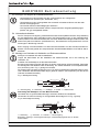
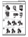
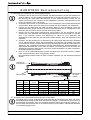
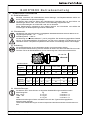
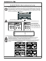
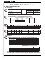
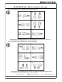
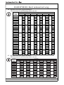
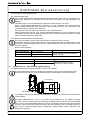
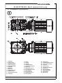
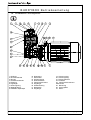
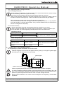
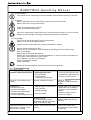
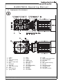
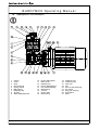
BUDDYBOX
Getriebe und Getriebemotoren
Gear and Gearmotor
Betriebsanleitung
Operating Manual
Nr.
991002
05/2007
BUDDYBOX Betriebsanleitung
Copyright 2007
Alle Rechte vorbehalten
Nachdruck, auch auszugsweise, ist nur mit ausdrücklicher
Genehmigung von Sumitomo Drive Technologies gestattet.
Die Angaben in dieser Einbau- und Betriebsanleitung wurden
mit grösster Sorgfalt auf ihre Richtigkeit geprüft. Trotzdem
kann für eventuelle fehlerhafte oder unvollständige Angaben
keine Haftung übernommen werden.
Technische Änderungen vorbehalten.
Inhaltsverzeichnis:
1.
2.
3.
4.
5.
6.
7.
8.
9.
10.
11.
12.
..............................
Seite
Allgemeine Hinweise . . . . . . . . . . . . . . . . . . . . . . . . . . . . . . . . . . . . . . .2
Hinweise zur Sicherheit . . . . . . . . . . . . . . . . . . . . . . . . . . . . . . . . . . . .2
Hinweise zum Transport . . . . . . . . . . . . . . . . . . . . . . . . . . . . . . .2
Anbau von Übertragungselementen . . . . . . . . . . . . . . . . . . . . . . . . .3
Einbau des Getriebes/Getriebemotors . . . . . . . . . . . . . . . . . . .3
5.1
Notwendige Hilfsmittel . . . . . . . . . . . . . . . . . . . . . . . . . . . . . . . . .3
5.2
Einbautoleranzen am Getriebe/Getriebemotor . . . . . . . . . . . . . .3
5.3
Prüfungen vor Beginn der Installationsarbeiten . . . . . . . . . . . . . .4
5.4
Vorbereitende Arbeiten . . . . . . . . . . . . . . . . . . . . . . . . . . . . . . . .4
5.5
Montage von Getrieben mit Hohlwelle u. Drehmomentstütze . . .4
5.5.1
Direktanbau . . . . . . . . . . . . . . . . . . . . . . . . . . . . . . . . . . . . . . . . .5
5.5.2
Drehmomentstütze mit kundenseitig bereitgestelltem Anbau . . . 5
5.5.3
Drehmomentsstütze Anbau optional . . . . . . . . . . . . . . . . . . . . . .5
5.5.4
Axiale Sicherung . . . . . . . . . . . . . . . . . . . . . . . . . . . . . . . . . . . . .5
5.5.4.1 Axiale Sicherung gegen Verschieben zur Maschine . . . . . . . . . .5
5.5.4 2 Axiale Sicherung gegen Lösen von der Welle . . . . . . . . . . . . . . .5
5.6
Montage von Getrieben mit Taper-Grip® Buchse . . . . . . . . . . . .6
5.7
Demontage des Getriebes von der Welle . . . . . . . . . . . . . . . . . .6
E l e k t r i s c h e I n s ta l l a t i o n . . . . . . . . . . . . . . . . . . . . . . .6
6.1
Sicherheitshinweise . . . . . . . . . . . . . . . . . . . . . . . . . . . . . . . . . . .6
6.2
Einsatzbereich . . . . . . . . . . . . . . . . . . . . . . . . . . . . . . . . . . . . . . .7
6.3
Aufstellung . . . . . . . . . . . . . . . . . . . . . . . . . . . . . . . . . . . . . . . . . .7
6.4
Kabeleinführungen . . . . . . . . . . . . . . . . . . . . . . . . . . . . . . . . . . . .7
6.5
Elektrischer Anschluss . . . . . . . . . . . . . . . . . . . . . . . . . . . . . . . . .8
6.6
Bremsmotoren . . . . . . . . . . . . . . . . . . . . . . . . . . . . . . . . . . . . . . .8
6.7
Umrichterbetrieb . . . . . . . . . . . . . . . . . . . . . . . . . . . . . . . . . . . . .9
6.8
Motorschutz . . . . . . . . . . . . . . . . . . . . . . . . . . . . . . . . . . . . . . . . .9
6.9
Fremdlüfter . . . . . . . . . . . . . . . . . . . . . . . . . . . . . . . . . . . . . . . . . .9
Inbetriebnahme des Antriebs . . . . . . . . . . . . . . . . . . . . . . . . . . . . . . .9
Hinweise zur Schmierung . . . . . . . . . . . . . . . . . . . . . . . . . . . . . . . . .10
8.1
Fettschmierung . . . . . . . . . . . . . . . . . . . . . . . . . . . . . . . . . . . . .10
8.1.1
Schmierungssystem für Standardtypen . . . . . . . . . . . . . . . . . . .10
8.2
Verwendete Fettsorten . . . . . . . . . . . . . . . . . . . . . . . . . . . . . . . .10
8.2.1
Fettmengen(g) für Fettwechsel bei Kegelrad Buddybox . . . . . .10
8.2.2
Fettmengen(g) für Fettwechsel bei Stirnrad Buddybox . . . . . . .10
8.3
Ölschmierung . . . . . . . . . . . . . . . . . . . . . . . . . . . . . . . . . . . . . . .10
8.4
Schmierarmaturen / Einbaulangen Kegelrad Buddybox . . . . . .11
8.5
Schmierarmaturen / Einbaulangen Stirnrad Buddybox . . . . . . .11
8.6
Ungefähre Ölmengen Kegelrad Buddybox . . . . . . . . . . . . . . . .12
8.7
Ungefähre Ölmengen Stirnrad Buddybox . . . . . . . . . . . . . . . . .12
8.8
Intervalle für Schmierstoffwechsel . . . . . . . . . . . . . . . . . . . . . . .13
8.8.1
Ölwechselintervalle . . . . . . . . . . . . . . . . . . . . . . . . . . . . . . . . . .13
8.8.2
Nachschmierintervalle bei Fettschmierung . . . . . . . . . . . . . . . .13
Inspektions- und Wartungsarbeiten . . . . . . . . . . . . . . . . . . . . . . . .13
9.1
Nachschmieren bei fettgeschmierten CYCLO Drive Stufen . . .13
9.2
Ölstandprüfen . . . . . . . . . . . . . . . . . . . . . . . . . . . . . . . . . . . . . . .14
9.3
Öl überprüfen . . . . . . . . . . . . . . . . . . . . . . . . . . . . . . . . . . . . . . .14
9.4
Öl wechseln . . . . . . . . . . . . . . . . . . . . . . . . . . . . . . . . . . . . . . . .14
Hinweise zu Betriebsstörungen . . . . . . . . . . . . . . . . . . . . . . . . . . . .14
Schnittzeichnung/Ersatzteile Kegelrad Buddybox . . . . . . . . . . .15
Schnittzeichnung/Ersatzteile Stirnrad Buddybox . . . . . . . . . . . .16
BB_DEU_ENG_991002_05_2007
Seite 1
BUDDYBOX Betriebsanleitung
1. Allgemeine Hinweise
Bitte beachten Sie in dieser Dokumentation unbedingt die folgenden Sicherheitshinweise!
Gefahr durch Elektrizität
Eine falsche Anwendung der Maschine kann zu Körperschäden, ernsthaften Verletzungen
und/ oder lebensgefährlichen Situationen führen.
Gefahr
Eine falsche Anwendung der Maschine kann zu Körperschäden, ernsthaften Verletzungen
und/ oder lebensgefährlichen Situationen führen.
Gefährliche Situation
Leichte Verletzungen können die Folge sein.
Schädliche Situation
Schäden am Antrieb oder der Umgebung können die Folge sein.
Hilfreiche Informationen
Entsorgung
Bitte achten Sie auf die geltenden Bestimmungen
2. Hinweise zur Sicherheit
Lesen Sie vor der Arbeit mit der Maschine (Montage, Betrieb, Wartung, Inspektion, usw.) diese
Betriebsanleitung aufmerksam durch, so dass Sie eine genaue Kenntnis über die richtige
Bedienung des CYCLO DRIVE, die anzuwendenden Sicherheitsbestimmungen und die zu
beachtenden Warnhinweise haben. Bewahren Sie diese Anleitung bei der Maschine auf, so
dass Sie bei Bedarf jederzeit nachschlagen können.
Transport, Montage, Schmierung, Betrieb, Wartung und Inspektion dürfen nur durch ausgebildetes technisches Fachpersonal durchgeführt werden; andernfalls besteht die Gefahr von
Verletzungen oder Schäden an der Maschine.
Niemals in sich bewegende Teile fassen und Fremdkörper von diesen Teilen fernhalten;
andernfalls besteht die Gefahr von Verletzungen oder Schäden an der Maschine.
Die Anlage darf nur für den vorgesehenen Verwendungszweck eingesetzt werden; andernfalls besteht die Gefahr von Verletzungen oder Schäden an der Maschine.
Die Anlage darf nur für den vorgesehenen Verwendungszweck eingesetzt werden; andernfalls besteht die Gefahr von Verletzungen oder Schäden an der Maschine.
3 . H i n w e i s e z u m Tr a n s p o r t
Die Lieferung muss sofort nach Erhalt auf etwaige Transportschäden untersucht werden. Ggf.
müssen diese sofort dem Transportunternehmen mitgeteilt werden. Wenn angenommen werden muss, dass ein Transportschaden den ordnungsgemäßen Betrieb einschränkt, muss die
Inbetriebnahme ausgeschlossen werden.
Es dürfen nur zweckmäßige und ausreichend dimensionierte Seilschlingen, die in die ggf.
vorhandenen Ringschrauben eingehängt oder um die Flanschverbindungen gelegt werden,
verwendet werden. Eingeschraubte Ringschrauben sind nur für das Gewicht des Antriebs
ausgelegt. Es dürfen keine zusätzlichen Lasten angehängt werden.
Generell gilt: Nicht die Zentrierbohrungen an den Wellenenden benutzen, um das Getriebe
mittels Ringschrauben etc. aufzuheben. Lagerschäden können die Folge sein.
Seite 2
BB_DEU_ENG_991002_05_2007
BUDDYBOX Betriebsanleitung
4. Anbau von Übertragungselementen
Die Montage erfolgt mit Hilfe der Zentrierbohrungen an den Wellenenden oder durch
Anwärmen der aufzuziehenden Teile auf maximal 100° C. Die Wellen sind mit einer Nut für
Paßfedern nach DIN 6885, Blatt 1, versehen. Die Bohrungen von Teilen, die auf die
Getriebewelle aufgesteckt werden, sollen mit den im jeweiligen Produktkatalog empfohlenen
Toleranzen gefertigt werden. Zur Sicherung gegen axiales Verschieben ist eine Stellschraube
oder ähnliches anzubringen. Um die Radiallasten gering zu halten, müssen Kettenräder,
Scheiben oder Zahnräder so nahe wie möglich an das Lager gesetzt werden (s. Bild unten
links). Wenn die Drehmomentübertragung über Ritzel, Kette etc. erfolgt, muss der Antrieb so
eingebaut werden, dass das Getriebegehäuse auf das Fundament gedrückt wird. Bei
Getrieben mit Hohl-Antriebswelle ist auf die Motorwelle MoS2-Paste oder Spray (z.B.
Molykote) aufzutragen, bevor das Gegenstück angebaut wird.
An- und Abtriebselemente wie Riemenscheiben, Kupplungen usw. müssen mit einem
Berührungsschutz abgedeckt werden !
Kupplungen, Scheiben, Zahnräder, Ketten usw., die auf die Getriebewellen aufgesetzt werden,
dürfen weder aufgepreßt noch aufgeschlagen werden, um Lagerschäden zu vermeiden.
5. Einbau des Getriebes/Getriebemotors
5.1 Notwendige Hilfsmittel
- Schraubenschlüsselsatz
- Drehmomentschlüssel für Befestigungsschrauben an Fuss-/Flanschgehäuse, Motorlaterne,
Klemmkupplungen usw.
- Aufziehvorrichtung
- Ausgleichselemente
- Korrosionschutz (z.B. MoS2-Paste)
Vor dem Einbau sind die mitgelieferten Schmierarmaturen (Atmungsfilter, Ölschauglas) an den
entsprechend gekennzeichneten Stellen zu montieren.
5.2 Einbautoleranzen am Getriebe/Getriebemotor
Wellen
k6 für Ø <
30 mm
h6 für Ø >
30 mm
Abtriebwellen
k6 für Ø <
50 mm
h6 für Ø >
50 mm
H7 bei Hohlwellen
Hohlwelle im Antrieb F7
Zentrierbohrungen nach DIN 332, Form DR
Antriebwellen
BB_DEU_ENG_991002_05_2007
Flansche
Zentrierrandtoleranz nach DIN 42948
IEC-Flansch antriebseitig
H8
Flansch abtriebseitig
h6
Seite 3
BUDDYBOX Betriebsanleitung
5.3 Prüfungen vor Beginn der Installationsarbeiten
- Übereinstimmung der Angaben auf dem Typenschild mit den vorliegenden
Dokumentationen (Zeichnungen, Stücklisten, usw.)
- Übereinstimmung der Leistungsdaten des eventuell vorhandenen Motors mit dem elektrischen Versorgungsnetz
- Der Antrieb darf keine Beschädigungen aufweisen
- Die vorgesehenen Schmierstoffe müssen entsprechend der Umgebungsbedingungen
passen und ggf. bereitgestellt werden
5.4 Vorbereitende Arbeiten
Der für Transport und Lagerung verwendete Korrosionsschutz (Marke Valvoline Tectyl 846/K19)
an den Wellenenden oder Hohlwellen und an den Zentriersitzen muss vor der Inbetriebnahme
entfernt werden. Der Korrosionsschutz kann mit einem alkalischen Reiniger entfernt werden, auf
keinen Fall jedoch mechanisch (Schleifmittel etc.). Das alkalische Lösungsmittel darf nicht mit
Dichtungen in Berührung kommen.
Beim Umgang mit Schmierstoffen und Korrosionsschutzmitteln sind die Schutzvorschriften für
Mensch und Umwelt gemäß den entsprechenden Sicherheitsdatenblättern nach DIN 52 900 zu
beachten.
5.5 Montage von Getrieben mit Hohlwelle und Drehmomentstütze
Reinigen und entfetten Sie alle Kontaktflächen.
Tragen Sie MoS2-Paste auf die Oberfläche der Maschinenwelle und in der Bohrung der
Hohlwelle auf.
Schieben Sie die Buddybox auf die Maschinenwelle.
Bei sehr enger Passung klopfen Sie leicht mit einem Holzhammer auf die Hohlwelle. Vermeiden
Sie Schläge auf das Gehäuse oder die Dichtung. Für sanftes Aufziehen ist es empfehlenswert,
eine Vorrichtung wie in Fig. 1 gezeigt zu benützen.
Die Toleranz der zylindrischen Bohrung ist H7. Für höhere Belastungen sollte die Passung zwischen Hohlwelle und Maschinenwelle enger gemacht werden. (Wir empfehlen js6 oder k6 als
Toleranz der Maschinenwelle).
Fig. 1 Montagevorrichtung
a
b
d
c
e
a = Sicherungsring b = Distanzring c = Axiallager d = Mutter e = Stiftschraube
Demontage der Buddybox von der Maschinenwelle
Vermeiden Sie zu große Krafteinwirkungen zwischen Gehäuse und Hohlwelle.
Verwenden Sie eine Vorrichtung zur sachgemäßen Demontage wie in Fig. 2 gezeigt.
Fig. 2 Demontagevorrichtung
i
h
A
f
g
A–
f = Distanzring
g = Schraube h = Scheibe i = Sicherungsring
Bemerkung: Montage-, Demontagevorrichtungen, sowie Befestigungsteile sind von Kunden
bereitzustellen.
Seite 4
BB_DEU_ENG_991002_05_2007
BUDDYBOX Betriebsanleitung
5.5.1 Direktanbau
5.5.2 Drehmomentsstütze mit kundenseitig bereitgestelltem Anbau
Durch die Bohrung im
Gehäuse mit zwei
Schrauben befestigen
5.5.3 Drehmomentsstütze Anbau optional
Durch die Bohrung im
Gehäuse mit zwei
Schrauben befestigen
5.5.4 Axiale Sicherung
5.5.4.1 Axiale Sicherung gegen Verschieben zur Maschine:
Lager
Sicherung mit Wellenschulter
Distanzring
Stellschraube
Sicherung mit Distanzring für
Wellen ohne Schulter
Anschlagring
Sicherung mit Anschlagring und
Stellschraube
5.5.4.2 Axiale Sicherung gegen Lösen von der Welle
Sicherungsring
Distanzring
Sicherung mit Distanzring und
Sicherungsring
BB_DEU_ENG_991002_05_2007
Druckscheibe
Sicherung mit Druckscheibe und
Spannschraube
Stellschraube
Anschlagring
Sicherung mit Anschlagring und
Stellschraube
Seite 5
BUDDYBOX Betriebsanleitung
5.6 Montage von Getrieben mit Taper-Grip® Buchse
1. Überprüfen Sie die Größe und den Zustand der Maschinenwelle, auf die das Getriebe aufgesteckt werden soll. Die zulässige Wellentoleranz ist für alle Durchmesser maximal h 11.
Die Bohrung der Taper-Grip® Klemmbuchse und die Maschinenwelle müssen frei von
Graten und Korrosion sein. Säubern sie alle Oberflächen mit einem Lösungsmittel und entfernen Sie sämtliche Fett- und Ölreste.
2. Schrauben leicht einölen und nacheinander in die Gewinde der Taper-Grip® Klemmbuchse
einschrauben. Stellen Sie sicher, dass die Schrauben auf der Rückseite nicht überstehen.
3. Fixieren Sie den Klemmring (bei HBB mit beiden Keilen) in den stirnseitigen Nuten der
Getriebehohlwelle. Drehen Sie dann die Taper-Grip® Klemmbuchse im Uhrzeigersinn in die
Hohlwelle, bis der Flansch der Buchse den Klemmring berührt.
4. Drehen Sie die Taper-Grip® Klemmbuchse soweit heraus, bis die Schrauben mit den
Vertiefungen in der Stirnseite des Klemmringes ausgerichtet sind und ein Spalt von mindestens 1 mm zwischen Flansch und Klemmring zu sehen ist. Zum Ausrichten der
Gewindebohrungen sollte eine der Schrauben entfernt werden. Dann alle Schrauben leicht
eindrehen.
5. Schieben Sie das Getriebe bis zur Zentrierung der Taper-Grip® Klemmbuchse vollständig
auf die Maschinenwelle. Ziehen Sie nacheinander die Schrauben gleichmäßig über Kreuz
und in mehreren Stufen mit einem Drehmomentschlüssel entsprechend der unten stehenden
Tabelle an. Der verbleibende Hohlraum zwischen Maschinenwelle, Getriebehohlwelle und
Taper-Grip® Klemmbuchse ist mit Fett zu befüllen. Auf diese Weise wird Korrosion am
Wellenende verhindert. Beim Einbau mit V-Drive, Drehmomentstütze, etc. bitte entsprechende Betriebsanleitungen beachten.
6. Nach ca. 20 bis 30 Betriebsstunden müssen die Taper-Grip® Schrauben auf die lt. Tabelle
unten vorgeschriebenen Werte nachgezogen werden.
Die Schraubenmomente sollten bei jeder normalen Inspektion (ca. alle 6 Monate) überprüft
werden.
Hohlwelle mit
Innengewinde
Maschinenwelle
BBB3
Größe
3A
3B
3C
3D
3E
HBB
Größe
Z
A
B
C
D
E
Fett
Taper-Grip®
Größe
C
E
F
G
H
J
Klemmring
Schrauben Größe
Anzahl
Code
6 x M 10
112B7003
6 x M 12
112E7003
6 x M 12
112B7003
6 x M 16
112G7003
6 x M 16
112G7003
8 x M 16
112G7003
Klemmring
Code
112C6146
112E6146
112F6146
112G6146
112H6146
112J6146
1 mm
Klemmbuchse
mit Aussengewinde
Anzugsmoment
[Nm]
50
75
140
250
300
300
5.7 Demontage der TAPER-GRIP® Klemmbuchse von der Welle
Schrauben lösen, bis sie außerhalb der Einbuchtungen des Druckrings sind. Dann mit einem
Kunststoffhammer kräftig auf die Taper-Grip-Buchse schlagen, um die Klemmung zu lösen und
das Getriebe freizusetzen. Zwei der Schrauben handfest gegen den Druckring anziehen, um
das Einrasten der Klemmbuchse in die andere Richtung zu vermeiden, während das Getriebe
von der Welle gezogen wird.
Seite 6
BB_DEU_ENG_991002_05_2007
BUDDYBOX Betriebsanleitung
6 . E l e k t r i s c h e I n s ta l l a t i o n
6.1 Sicherheitshinweise
Montage, Anschluss und Inbetriebnahme sowie Wartungs- und Reparaturarbeiten dürfen nur
durch qualifiziertes Fachpersonal erfolgen.
Vor Beginn jeder Arbeit am Motor oder Getriebemotor, besonders aber vor dem Öffnen von
Abdeckungen aktiver Teile, muss der Motor vorschriftsmäßig freigeschaltet sein.
Die 5 Sicherheitsregeln nach DIN VDE 0105 sind zu beachten.
Diese Elektromotoren entsprechen den gültigen Normen und Vorschriften und erfüllen die
Forderungen der Niederspannungsrichtlinie 73/23/EWG.
6.2 Einsatzbereich
Die Motoren sind völlig verschlossen und luftgekühlt. Standardschutzart ist IP 55 mit Bremse IP 44.
Umgebungstemperatur: -10° . . . +40°C
Aufstellungshöhe: < 1000 m
Die Wicklung ist in Isolationsklasse F (150°C) ausgeführt. Bei bestimmungsgemäßem Betrieb
können an der Motoroberfläche Temperaturen von über 100°C auftreten. Eine Berührung muss
verhindert werden. Temperatur empfindliche Teile dürfen nicht befestigt werden oder anliegen.
6.3 Aufstellung
Die Lüftungsöffnungen in der Lüfterhaube dürfen nicht verschlossen werden.
Für eine ausreichende Kühlung darf der Abstand der Haube zur Wand das Maß FB nicht unterschreiten. FA ist der Mindestabstand, der zur Demontage der Lüfterhaube erforderlich ist.
FA oder FB
Standard Motor
Motorbaugröße:
FB (mm):
FA (mm):
63 - 71
80
90
100 112-132S 132M-160M
160L
180M 180L
20
20
20
20
20
25
30
30
30
48
49
52
56
60
75
130
155
170
63 - 71
80
90
100 112-132S 132M-160M
20
20
20
20
25
25
30
30
30
61
93
115
121
132
170
220
367
370
Bremsmotor
Motorbaugröße:
FB (mm):
FA (mm):
160L
180M 180L
6.4 Kabeleinführungen
Die Motoren der F-Serie können mit folgenden Kabeleinführungen bestückt werden.
Motor-Baugröße
Pg
Metrisch
063 - 132 S
2 x Pg 16
2 x M 25 x 1,5
132M - 160
2 x Pg 21
2 x M 32 x 1,5
180L
2 x Pg 42
2 x M 50 x 1,5
Kabelverschraubungen müssen mindestens der auf dem Typenschild angegebenen
Motorschutzart genügen.
Unbenutzte Kabeleinführungen müssen entsprechend der Motorschutzart verschlossen werden.
BB_DEU_ENG_991002_05_2007
Seite 7
BUDDYBOX Betriebsanleitung
6.5 Elektrischer Anschluss
Technische Daten sowie Angaben zu den zulässigen Einsatzbedingungen entnehmen Sie bitte
dem Leistungsschild und dieser Betriebsanleitung, sowie dem aktuellen Katalog. Angaben über
Sonderauführungen finden Sie auf Ihrer Auftragsbestätigung. Bei eventuellen Unklarheiten
empfehlen wir dringend, unter Angabe der Typenbezeichnung und der Seriennummer im Werk
oder Ihrem Vertriebszentrum rückzufragen.
Den Schutzleiter an dieser Klemme
anschließen.
Im Klemmkasten befindet sich ein Schaltbild. Die Motoren können am Klemmbrett je nach
Anschlussspannung wie folgt geschaltet werden:
Für die angegebenen
Spannungen gilt der
Bemessungsspannungsbereich nach EN 60 034-1
mit ± 5% Spannungs- oder
± 2% Frequenzabweichung.
Für die Gewindebolzen des Klemmbrettes gelten folgende Anzugsmomente:
Bolzengewinde:
zulässiges Anzugsmoment in Nm
M4
1,2
M5
2,5
M6
4,0
M8
7,5
6.6 Bremsmotoren
Der Anschluß der Bremsmotoren erfolgt gemäß folgenden Schaltbildern.
Die Bremse ist bereits verdrahtet. Für eine separate Spannungsversorgung der Bremse
müssen die Verbindungen vom Klemmbrett zum Gleichrichter abgeklemmt werden.
Die Bremssteuerspannung ist auf dem Leistungsschild vermerkt.
Für eine schnelle Einfallzeit der Bremse (gleichstromseitiges Schalten) muss eine separate
Leitung zu einem externen Kontakt geführt werden. Der Kontakt ist mit einem Varistor zu
schützen.
Schnellwirkende Bremse
Standard Bremse
Seite 8
BB_DEU_ENG_991002_05_2007
BUDDYBOX Betriebsanleitung
6.7 Umrichterbetrieb
Beim Betrieb der F-Motoren am Frequenzumrichter sind die EMV - Hinweise des
Umrichterherstellers zu beachten. Entsprechende Entstörmaßnahmen sind zu treffen. Es sollten
abgeschirmte Leitungen und Kabeleinführungen aus Metall vorgesehen werden.
Das Drehmoment des Motors hängt vom jeweiligen Umrichter ab.
Bei Bremsmotoren muss der Gleichrichter der Bremse mit einer separaten, sinusförmigen
Spannung versorgt werden.
Der Motor ist durch Kaltleiter, Thermokontakte und/ oder durch Fremdlüfter vor übermäßiger
Überhitzung zu schützen.
6.8 Motorschutz
Motorschutzschalter (Überstromschutz) sind entsprechend der Spannung auf den auf dem
Leistungsschild angegebenen Stromwert einzustellen.
Thermokontakte sind generell als Öffner ausgeführt .
Der Widerstandwert von Kaltleitern (PTC) bei 20°C ist nicht aussagekräftig. Der Wert kann zwischen 90W und max. 750 W variieren.
6.9 Fremdlüfter
Der Anschluss der Fremdlüfter erfolgt im Klemmenkasten auf der Fremdlüfterhaube.
Der Fremdlüftermotor sollte eine separate Spannungsversorung erhalten.
ACHTUNG: Je nach Steuerung kann der Fremdlüfter in Betrieb sein, auch wenn der Motor nicht
dreht.
Leistungsschilder und Anschlussbilder zu dem Fremdlüfter befinden sich im Klemmenkasten.
Baugrößenabhängig sind diese unterschiedlich ausgeführt. Der Lüftermotor kann wie folgt ausgeführt sein:
- Spaltpolmotor: Anschluss, L1 und N (Drehrichtungsumkehr nicht möglich)
- Kondensatormotor:
L1
N
U1
Z1
Z2
U2
Linkslauf
L1
N
U1
Z2
Z1
U2
Rechtslauf
- Drehstrommotor: In Stern- oder Dreieckschaltung, je nach Spannung wie im Kapitel
"Elektrischer Anschluss".
- Drehrichtungsumkehr durch vertauschen zweier Phasen.
7. Inbetriebnahme des Antriebs
Auf die genaue Beachtung der Sicherheitshinweise wird nochmals ausdrücklich hingewiesen.
Netzverhältnisse und Leistungsschildangaben müssen übereinstimmen. Für Zusatzeinrichtungen, z.B. Stillstandsheizungen, sind zusätzliche Angaben im Motorklemmenkasten.
Anschlusskabel sind im Querschnitt den Motorströmen anzupassen.
Die Installation muss unter Beachtung der gültigen Vorschriften von entsprechend geschultem
Fachpersonal erfolgen.
Vor dem Einschalten des Getriebemotors ist zu überprüfen, dass alle Sicherheitsbestimmungen
eingehalten werden, die Maschine ordnungsgemäß montiert und ausgerichtet ist, alle Befestigungsteile und Erdungsanschlüsse fest angezogen sind, die Hilfs- und Zusatzeinrichtungen
funktionsfähig und ordnungsgemäß angeschlossen sind und die Paßfeder eines eventuell
vorhandenen zweiten Wellenendes gegen Wegschleudern gesichert ist.
Der Getriebemotor ist, falls möglich, ohne Last einzuschalten. Läuft er ruhig und ohne abnormale Geräusche, wird der Motor mit der Arbeitsmaschine belastet. Bei der Inbetriebnahme empfiehlt sich eine Beobachtung der aufgenommenen Ströme, wenn der Motor mit seiner
Arbeitsmaschine belastet ist, damit mögliche Überlastungen und netzseitige Asymmetrien sofort
erkennbar sind.
Achtung: Alle Getriebe werden ab Werk aus Sicherheitsgründen ohne Ölfüllung geliefert und
müssen vor Inbetriebnahme entsprechend befüllt werden.
BB_DEU_ENG_991002_05_2007
Seite 9
BUDDYBOX Betriebsanleitung
8. Hinweise zur Schmierung
8.1 Fettschmierung
8.1.1 Schmierungssystem für Standardtypen
Bevel
Buddybox
3A10*; 3A11*
3A12*; 3B12*
3A14*; 3B14*; 3C14*
3B16*; 3C16*; 3D16*
3C17*; 3D17*, 3E17*
Helical
Buddybox
Abtriebsstufe
(Bevel/Helical)
Z609*; A610*, B612*
C614*
D616*
E617*
Antriebsstufe (CYCLO)
Horizontale Antriebsstufe Vertikale Antriebsstufe
Fett
Fett
(wartungsfrei)
(wartungsfrei)
Ölbad
Ölbad
Fett
8.2 Verwendete Fettsorten
Die fettgeschmierten CYCLO-Drive Stufen sind ab Werk mit Schmierstoff befüllt.
Die verwendete Fettsorte ist der nachstehenden Tabelle zu entnehmen.
Kegelrad Buddybox Stirnrad Buddybox
Größe
Größe
2A10*; 2A11*
Z609*; A610*
Umgebungs2A12*; 2B12*
B612*
temperatur [°C]
2A14*; 2B14*; 2C14*
-10 ~ 40
C614*; D616*
2B16*; 2C16*; 2D16*
2C17*; 2D17*
E617*
2E17*
Übersetzung
11 und 18
Übersetzung
>/= 21
SHELL
Alvania EPR 0
Unirex N2
ESSO
8.2.1 Fettmengen (g) für Fettwechsel bei Kegelrad Buddybox
6100 6100DA 6110 6120 6120DA 6120DB 6140 6140DA 6140DB 6140DC 6160 6160DA 6160DB 6170 6170DA 6170DB 6170DC
Größe
6105 6105DA 6115 6125 6125DA 6125DB 6145 6145DA 6145DB 6145DC 6165 6165DA 6165DB 6175 6175DA 6175DB 6175DC
Einbaulage
140
165
200 330
350
420
oil
475
540
590
Öl
840
890
Öl
1090
1140
1330
1,3,5,6
Einbaulage
140
165
200 330
350
420
640
475
540
590
1120
840
890
1440
1090
1140
1330
2,4
8.2.2 Fettmengen (g) für Fettwechsel bei Stirnrad Buddybox
Baugröße
6095 6095DA 6100 6100DA 6120 6120DA 6120DB 6140 6140DA 6140DB 6140DC 6160 6160DA 6160DB 6170 6170DA 6170DB 6170DC
6095 6095DA 6105 6105DA 6125 6125DA 6125DB 6145 6145DA 6145DB 6145DC 6165 6165DA 6165DB 6175 6175DA 6175DB 6175DC
Einbaulage
1,2,3,4
90
115
140
165
330
350
420
Öl
475
540
590
Öl
840
890
Öl
1090
1140
1330
Einbaulage
5,6
90
115
140
165
330
350
420
640
475
540
590
1120
840
890
1440
1090
1140
1330
8.3 Ölschmierung
Empfohlene Schmierstoffe
Geeignet sind alle Schmierstoffe, die die Anforderungen nach DIN 51517 Teil 3 erfüllen. Je nach
Umgebungs- oder Betriebstemperatur muss die richtige Ölviskosität verwendet werden.
Schmierstoff nach
DIN 57517 Teil 3
-20°C
mögliche Betriebstemperaturen °C
Umgebung
0°
+20°
+40°
+60°
+80°
+100°
CLP 68
CLP 100
CLP 150
CLP 220
CLP 320
Hersteller
ARAL
AVIA
BP
Castrol
Marke
Degol BG
Gear RSX
Energol GR-XP
Alpha MW
Hersteller
DEA
ELF
ESSO
KLÜBER
Marke
Falcon CLP
Reductelf SP
Spartan EP
Klüberoil GEM 1
Hersteller
MOBIL
OPTIMOL
SHELL
TOTAL
Einige Typen müssen an verschiedenen Stellen mit Öl befüllt werden. Lage der Ölarmaturen entnehmen Sie bitte den Zeichnungen unter Punkt 8.4 und und 8.5 und Ölmengen den Tabellen unter
Punkt 8.6 und 8.7.
Seite 10
BB_DEU_ENG_991002_05_2007
BUDDYBOX Betriebsanleitung
8.4 Schmierarmaturen / Einbaulagen Kegelrad Buddybox
Hinweis: Die CYCLO DRIVE Stufe Y2 und Y4 sind bei Kegelrad Buddybox fettgeschmiert.
Bereitstellung und Entsorgung von Öl ist nicht erforderlich.
8.5 Schmierarmaturen / Einbaulagen Stirnrad Buddybox
Hinweis: Die CYCLO DRIVE Stufe Y5 und Y6 sind bei Stirnrad Buddybox fettgeschmiert.
Bereitstellung und Entsorgung von Öl ist nicht erforderlich.
O
Öleinfüllschraube
BB_DEU_ENG_991002_05_2007
Ölstandsschraube
Ölablassschraube
Seite 11
BUDDYBOX Betriebsanleitung
8.6 Ungefähre Ölmengen Kegelrad Buddybox
Schmierarmaturen und Einbaulage siehe unter 8.4
Bevel
1
Buddybox
Größe
Bevel Cyclo
3A10*
G
3A10*DA
G
3A11*
G
1,1
3A12*
G
3A12*DA
G
3A12*DB
G
3A14*
0,3
3B12*
G
3B12*DA
G
3B12*DB
G
1,8 0,45
3B14*
3B14*DA
G
3B14*DB
G
3B16*
0,75
3C14*
0,45
3C14*DA
G
3C14*DB
G
3,3
3C14*DC
G
3C16*
0,75
3C16*DA
G
3C17*
1,05
3D16*
0,7
3D16*DA
G
3D16*DB
G
4,4
3D17*
0,9
3D17+DA
G
3D17*DB
G
3D17*DC
G
3E17*
0,9
3E17*DA
G
7,4
3E17*DB
G
3E17*DC
G
2
Bevel Cyclo
G
G
G
1,0
G
G
G
G
G
G
G
1,4
G
G
G
G
G
G
G
3,5
G
G
G
G
G
G
G
5,0
G
G
G
G
G
G
7,3
G
G
Einbaulage
3
4
Bevel Cyclo Bevel Cyclo
G
G
G
G
G
G
1,1
1,0
G
G
G
G
G
G
0,3
G
G
G
G
G
G
G
1,8 0,45 1,8
G
G
G
G
G
0,75
G
0,45
G
G
G
G
G
3,3
4,4
G
G
0,75
G
G
G
1,05
G
0,7
G
G
G
G
G
4,4
4,2
0,9
G
G
G
G
G
G
G
0,9
G
G
G
7,4
6,0
G
G
G
G
5
Bevel Cyclo
G
G
G
1,7
G
G
G
0,3
G
G
G
2,3 0,45
G
G
0,75
0,45
G
G
3,6
G
0,75
G
1,05
0,7
G
G
5,6
0,9
G
G
G
0,9
G
7,2
G
G
6
Bevel Cyclo
G
G
G
1,6
G
G
G
0,3
G
G
G
2,5 0,45
G
G
0,75
0,45
G
G
5,3
G
0,75
G
1,05
0,7
G
G
6,0
0,9
G
G
G
0,9
G
10,6
G
G
8.7 Ungefähre Ölmengen Stirnrad Buddybox
Schmierarmaturen und Einbaulage siehe unter 8.5.
Stirnrad
Buddybox
Größe
Z609*
Z609*DA
A610*
A610*DA
B612*
B612*DA
B612*DB
C614*
C614*DA
C614*DB
D616*
D616*DA
D616*DB
E617*
E617*DA
E617*DB
Seite 12
Einbaulage
1
Stirnrad
0,6
0,8
1,0
1,7
2,7
3,5
2
Cyclo
G
G
G
G
G
G
G
0,4
G
G
0,7
G
G
0,9
G
G
Stirnrad
0,6
0,9
1,5
2,1
3,5
4,2
3
Cyclo
G
G
G
G
G
G
G
0,4
G
G
0,7
G
G
0,9
G
G
Stirnrad
0,5
0,7
1,0
1,3
2,0
2,5
4
Cyclo
G
G
G
G
G
G
G
0,4
G
G
0,7
G
G
0,9
G
G
Stirnrad
0,6
0,9
1,5
2,1
3,5
4,2
5
Cyclo
G
G
G
G
G
G
G
0,4
G
G
0,7
G
G
0,9
G
G
Stirnrad
1,1
1,5
2,0
4,7
7,0
9,0
6
Cyclo
G
G
G
G
G
G
G
G
G
G
G
G
G
G
G
G
Stirnrad
1,0
1,4
1,8
3,5
5,5
7,0
Cyclo
G
G
G
G
G
G
G
G
G
G
G
G
G
G
G
G
BB_DEU_ENG_991002_05_2007
BUDDYBOX Betriebsanleitung
8.8 Intervalle für Schmierstoffwechsel
8.8.1 Ölwechselintervalle
Der richtige Ölstand sollte alle 5000 Stunden überprüft werden. Wenn das Öl verschmutzt, verbrannt oder zähflüssig ist, wechseln Sie das Öl sofort und spülen Sie, falls erforderlich, das
Getriebe.
Der Ölstand kann an der Ölstandsanzeige überprüft werden (siehe 8.4 und 8.5.)
Unter normalen Betriebsbedingungen empfehlen wir einen Ölwechsel alle 10.000 Stunden.
Kürzere Ölwechselintervalle (alle 3.000 bis 5.000 Stunden) erhöhen die Lebensdauer. Die
Intervalle sollten nicht länger als 2 Jahre sein.
Ein Ölwechsel nach den ersten 500 Stunden ist sehr empfehlenswert.
Obige Empfehlungen können unter anderen Betriebsbedingungen wie hohe Temperatur, hohe
Feuchtigkeit oder korrosive Umgebung geändert werden. Wenn eine dieser Situationen vorliegt,
müssen häufigere Ölwechsel stattfinden.
8.8.2 Nachschmierintervalle bei Fettschmierung
Alle Typen mit ESSO Unirex N2 sind wartungsfrei für 20.000 Std. oder 4-5 Jahre.
Alle anderen fettgeschmierten Typen müssen nach 500 Betriebsstunden, spätestens jedoch nach
2 Monaten, erstmals nachgeschmiert werden. Weitere Nachschmierungen entsprechend unten
stehender Tabelle.
Nachschmierungsfristen
Einsatzbedingungen Zeitpunkt zur Nachschmierung Anmerkungen
bis 10 Stunden/Tag alle 3 - 6 Monate
Bei erschwerten Betriebsbedingungen
müssen die Nachschmierungsfristen
10 - 24 Stunden/Tag alle 500 - 1000 Stunden
verkürzt werden
Fristen für den Fettwechsel
Bereich
Zeitpunkt des Fettwechsels
Antrieb und Übersetzung
alle 2 - 3 Jahre
Abtrieb
alle 3 - 5 Jahre
Anmerkungen
Bei erschwerten Betriebsbedingungen
müssen die Fristen für den
Fettwechsel verkürzt werden
9 . I n s p e k t i o n s - u n d Wa r t u n g s a r b e i t e n
9.1 Nachschmieren bei fettgeschmierten CYCLO Drive Stufen
Die Schmierkontrollschraube am Gehäuse abschrauben und mit einer Fettpresse durch den
Schmiernippel am Flansch auf der Antriebseite oder am Motorflansch Fett nachschmieren.
Schmiernippel
Ölkontrollschraube
Die Getriebe während des Betriebs nachschmieren, um eine gute Zirkulation des Schmierfetts
sicherzustellen.
Bei jedem Nachschmieren muss ca. ein Drittel bis die Hälfte der in der Tabelle in Kapitel
8.2.1/8.2.2 für die 1. Stufe genannten Fettmenge nachgefüllt werden. Falls zuviel Fett nachgefüllt
wird, kann es durch die Betriebserwärmung zu einer unzulässigen Erwärmung des Schmierstoffs
kommen, oder es kann durch Überdruck Fett in den Motor gelangen oder zu Leckagen kommen.
Das an den Schmierkontrollschrauben ausgetretene Überschussfett sauber abwischen und
fachgerecht entsorgen.
Seite 13
BB_DEU_ENG_991002_05_2007
BUDDYBOX Betriebsanleitung
9.2 Ölstand prüfen
Der Ölstand kann an der Ölstandsanzeige überprüft werden (s. Punkt 8.4 u. 8.5
Schmierarmaturen)
9.3 Öl überprüfen
· Getriebemotor spannungslos schalten, gegen unbeabsichtigtes Wiedereinschalten sichern.
· Abwarten, bis Getriebe abgekühlt ist - Verbrennungsgefahr!
· An Ölablassschraube etwas Öl entnehmen.
· Ölbeschaffenheit überprüfen.
· Viskosität überprüfen.
· Zeigt das Öl visuell starke Verschmutzung wird empfohlen, außerhalb der unter Kapitel 8.2.4
"Ölwechselintervalle" vorgegebenen Wartungsintervalle das Öl zu wechseln.
· Die entnommene Ölprobe ist fachgerecht zu entsorgen.
9.4 Öl wechseln
· Getriebemotor spannungslos schalten, gegen unbeabsichtigtes Wiedereinschalten sichern.
· Abwarten, bis Getriebe abgekühlt ist - Verbrennungsgefahr!
· Ölwechsel nur bei betriebswarmem Getriebe durchführen.
· Gefäß unter Ölablassschraube stellen.
· Ölstandsanzeige, Entlüftungsschraube/-ventil und Ölablassschraube entfernen.
· Öl vollständig ablassen.
· Ölablassschraube eindrehen.
· Neues Öl entsprechend der Ölempfehlung über die Öleinfüllschraube einfüllen.
Vor Verwendung anderer Ölsorten Rücksprache mit Sumitomo Drive Technologies.
· Ölmenge entsprechend Kapitel 8.2.3 "Ölmengen" einfüllen.
· An der Ölstandsanzeige überprüfen.
· Entlüftungsschraube/-ventil eindrehen.
· Das abgelassene Öl ist fachgerecht zu entsorgen.
10. Mögliche Betriebsstörungen - Fehlerursachen und Maßnahmen
Betriebsstörung
ungewöhnliche, gleichmäßige Laufgeräusche
ungewöhnliche, ungleichmäßige Laufgeräusche
Öl tritt aus 1)
- am Getriebedeckel
- am Motorflansch
- am Motorwellendichtring
- am Getriebeflansch
- am abtriebsseitigen
Wellendichtring
Öl tritt aus am
Entlüftungsventil
Abtriebwelle dreht nicht,
obwohl Motor läuft oder
Antriebswelle gedreht wird
mögliche Ursache
Fehlerbehebung
1. Geräusch abrollend/mahlend:
1. Öl überprüfen (siehe
Lagerschaden
Inspektions- und Wartungs2. Geräusch klopfend:
arbeiten), Lager wechseln
Unregelmäßigkeit in der Über- 2. Kundendienst anrufen
setzung
Fremdkörper im Öl
1. Dichtung im Getriebedeckel
undicht
2. Dichtung defekt
3. Getriebe nicht entlüftet
- zu viel Öl
- Antrieb in der falschen Bauform
eingesetzt
- häufiger Kaltstart (Öl schäumt) und /
oder hoher Ölstand
Wellen-Nabenverbindung im
Getriebe unterbrochen
Öl überprüfen (s. Inspektions- und
Wartungsarbeiten) Antrieb stillsetzen, Kundendienst anrufen
1. Schrauben am Getriebedeckel nachziehen und
Getriebe beobachten. Tritt
weiter Öl aus: Kundendienst
anrufen
2. Kundendienst anrufen
3. Getriebe entlüften (s.
Bauformen)
Ölmenge korrigieren (s. Ölstand
überprüfen).
Entflüftungsventil korrekt anbringen und Ölstand korrigieren (s.
Ölstand überprüfen).
Getriebe/Getriebemotor zur
Reparatur einschicken
1) Am Wellendichtring in geringen Mengen austretendes Öl/Fett ist in der Einlaufphase (24 Stunden Laufzeit)
als normal anzusehen (s. auch DIN 3761).
Seite 14
BB_DEU_ENG_991002_05_2007
BUDDYBOX Betriebsanleitung
11 . E r s a t z t e i l e Kegelradgetriebe
1
2
3
4
5
6
7
8
9
10
11
12
Gehäuse
Abstimmring
Kegelrollenlager
Wellendichtring
Abtriebhohlwelle
Paßfeder
Kegelrad
Nilos ring
Kegelrollenlager
Abstimmring
Sechskantschraube
Federring
BB_DEU_ENG_991002_05_2007
13
14
15
16
17
18
19
20
21
23
24
25
Motor
O-Ring
O-Ring
Abtriebsdeckel
Sechskantschraube
Nilos ring
Ölstandsschlauch
Verschlussschraube
Atmungsfilter
Ringschraube
Ölstandsschlauch
Atmungsfilter
26
27
28
29
30
31
32
33
34
35
36
Distanzring
Zylinderkopfschraube
Nord-Lock-Scheibe
Scheibe
Abstimmring
Verschlussschraube
Öldichtung
Kegelritzelwelle
Flanschgehäuse
Stufenwelle
Bolzenring
Seite 15
BUDDYBOX Betriebsanleitung
1 2 . E r s a t z t e i l e Stirnradgetriebe
1
2
3
4
5
6
7
8
9
Gehäuse
Verschlussdeckel
Stirnrad
Sechskantschraube
Federring
Kugellager
Sicherungsring
Wellendichtring
Hohlwelle f. Taper Grip®
Seite 16
10
11
12
13
14
15
16
17
18
Distanzring
Motorwelle
Sicherungsring
Distanzscheibe
Verschlussschraube
Kugellager
Wellendichtring
Ritzelwelle
Kugellager
19 Sicherungsring
20 Sicherungsring
21 Dichtungsdeckel
22 Paßfeder
23 Verschlussschraube24
Stufenwelle
25 Bolzenring
26 Atmungsfilter
27 Motor
BB_DEU_ENG_991002_05_2007
BUDDYBOX Operating Manual
Copyright 2007 Sumitomo Drive Technologies
All rights reserved
Reproduction in part or whole is not permitted without our
prior approval.
Whilst every care has been taken in preparation of this manual, no liability can be accepted for any errors or omissions.
Content:
1.
2.
3.
4.
5.
6.
7.
8.
9.
10.
11.
11.
Subject to technical changes.
page
General information . . . . . . . . . . . . . . . . . . . . . . . . . . . . . . . . . . . . . . . .2
Safety advice . . . . . . . . . . . . . . . . . . . . . . . . . . . . . . . . . . . . . . . . . . . . . .2
Transportation . . . . . . . . . . . . . . . . . . . . . . . . . . . . . . . . . . . . . . . . . . . . .2
Connection of other transmission components . . . . . . . . . . . . . .3
Gear/gearmotor Installation . . . . . . . . . . . . . . . . . . . . . . . . . . . . . . . .3
5.1
Necessary tools . . . . . . . . . . . . . . . . . . . . . . . . . . . . . . . . . . . . . .3
5.2
Assembly tolerances . . . . . . . . . . . . . . . . . . . . . . . . . . . . . . . . . .3
5.3
To check before installation . . . . . . . . . . . . . . . . . . . . . . . . . . . . .4
5.4
Getting the unit ready for installation . . . . . . . . . . . . . . . . . . . . . .4
5.5
Installation of gears with hollow shaft and torque arm . . . . . . . .4
5.5.1
Direct mounting method . . . . . . . . . . . . . . . . . . . . . . . . . . . . . . . .5
5.5.2
Torque arm mounted to customer’s machine . . . . . . . . . . . . . . . 5
5.5.3
Torque arm Tie-rod type (option) . . . . . . . . . . . . . . . . . . . . . . . . .5
5.5.4
Buddybox to be secured to driven shaft . . . . . . . . . . . . . . . . . . .5
5.5.4.1 How to secure Buddybox not to move to the machine side . . . . . . . . . .5
5.5.4.2 How to secure Buddybox not to move off from the machine side . . . . . .5
5.6
Installation with Taper-Grip® Bush . . . . . . . . . . . . . . . . . . . . . . .6
5.7
Removal of Taper-Grip® Bush . . . . . . . . . . . . . . . . . . . . . . . . . . .6
Electrical connection . . . . . . . . . . . . . . . . . . . . . . . 7
6.1
Safety advise . . . . . . . . . . . . . . . . . . . . . . . . . . . . . . . . . . . . . . . .7
6.2
Range of use . . . . . . . . . . . . . . . . . . . . . . . . . . . . . . . . . . . . . . . .7
6.3
Installation . . . . . . . . . . . . . . . . . . . . . . . . . . . . . . . . . . . . . . . . . .7
6.4
Cable inlet thread sizes . . . . . . . . . . . . . . . . . . . . . . . . . . . . . . . .7
6.5
Electrical connection . . . . . . . . . . . . . . . . . . . . . . . . . . . . . . . . . .8
6.6
Brake motors . . . . . . . . . . . . . . . . . . . . . . . . . . . . . . . . . . . . . . . .8
6.7
Installation with frequency inverters . . . . . . . . . . . . . . . . . . . . . . .9
6.8
Motor protection . . . . . . . . . . . . . . . . . . . . . . . . . . . . . . . . . . . . . .9
6.9
Forced ventilator . . . . . . . . . . . . . . . . . . . . . . . . . . . . . . . . . . . . .9
Start up . . . . . . . . . . . . . . . . . . . . . . . . . . . . . . . . . . . . . . . . . . . . . . . . . . .9
Lubrication . . . . . . . . . . . . . . . . . . . . . . . . . . . . . . . . . . . . . . . . . . . . . . .10
8.1
Grease lubrication . . . . . . . . . . . . . . . . . . . . . . . . . . . . . . . . . . .10
8.1.2
Lubrication for standard units . . . . . . . . . . . . . . . . . . . . . . . . . .10
8.2
Grease in use . . . . . . . . . . . . . . . . . . . . . . . . . . . . . . . . . . . . . .10
8.2.1
Grease quantity (g) for grease change Bevel Buddybox . . . . . .10
8.2.2
Grease quantity (g) for grease change HelicalBuddybox . . . . .10
8.3
Oil types . . . . . . . . . . . . . . . . . . . . . . . . . . . . . . . . . . . . . . . . . . .10
8.4
Lubrication devices Bevel Buddybox . . . . . . . . . . . . . . . . . . . . .11
8.5
Lubrication devices Helical Buddybox . . . . . . . . . . . . . . . . . . . .11
8.6
Oil quantities approximately for Bevel Buddybox . . . . . . . . . . .12
8.7
Oil quantities approximately for Helical Buddybox . . . . . . . . . .12
8.8
Regreasing and oil change intervals . . . . . . . . . . . . . . . . . . . . .13
8.8.1
Oil change intervals . . . . . . . . . . . . . . . . . . . . . . . . . . . . . . . . . .13
8.8.2
Grease lubrication . . . . . . . . . . . . . . . . . . . . . . . . . . . . . . . . . . .13
Inspection and maintenance . . . . . . . . . . . . . . . . . . . . . . . . .13
9.1
Grease refill for grease lubricated CYCLO Drive units . . . . . . .13
9.2
Oil level check . . . . . . . . . . . . . . . . . . . . . . . . . . . . . . . . . . . . . .14
9.3
Oil check . . . . . . . . . . . . . . . . . . . . . . . . . . . . . . . . . . . . . . . . . .14
9.4
Oil change . . . . . . . . . . . . . . . . . . . . . . . . . . . . . . . . . . . . . . . . .14
Troubleshooting . . . . . . . . . . . . . . . . . . . . . . . . . . . . . . . . . . . . . . . . . .14
Sectional drawing/spare parts Bevel Buddybox . . . . . . . . . . . . .15
Sectional drawing/spare parts Bevel Buddybox . . . . . . . . . . . . .16
BB_DEU_ENG_991002_05_2007
Page 1
BUDDYBOX Operating Manual
1. General information
Please observe the following warnings
Electrical hazard
Misapplication of the machine may be dangerous, risk of severe or fatal injury.
Imminent danger
Misapplication of the machine may be dangerous and lead to severe injures.
Dangerous situation
Risk of physical injury
Damaging situation
Risk of machine damage.
H e l pf u l i n f o r m a t i o n
Disposal
Please observe legal /environmental regulations.
2. Safety advice
Do not attempt to install or operate the CYCLO DRIVE until all of these instructions on assembly, operation, maintenance and inspection and hazards are read and thoroughly understood.
Please keep these instructions next to the unit in operation to check at any time when necessary.
Transportation, assembly, lubrication, operation, maintenance and inspection should only be
done by qualified personnel, so as to avoid personal injury or damage to property.
Do not touch moving mechanical components and make sure these parts are clear of obstructions. Failure to follow these instructions may result in personal injury, unit failure or damage to
property.
Only operate the unit in the application it was intended. Misapplication may result in physical
injury or damage to machinery.
3 . Tr a n s p o r ta t i o n r e c o m m e n d a t i o n s
The units must be checked for any transportation damage immediately upon receipt. Any damages should be reported to the carrier without delay. If there is any evidence of damage which
may put at risk the function of the CYCLO DRIVE, do not install the unit.
Lifting harnesses of suitable and adequate size are to be used; these are to be hooked into the
eye bolts or laid round the flange connections. Eye bolts on the gearbox are dimensioned for
the weight of the unit, no additional loads are allowed.
Caution: do not use the central bores in the shaft ends for lifting the drive with hooked bolts,
etc. This could result in damage to the bearings.
Page 2
BB_DEU_ENG_991002_05_2007
BUDDYBOX Operating Manual
4 . C o n n e c t i o n o f o t h e r t r a n s m i s s i o n c o m p o n e n ts
Assembly is carried out using the central bores in the ends of the shaft or by heating the parts
to be mounted to a maximum of 100°C. The shafts have been fitted with keyways to DIN 6885,
sheet 1. Bores of the parts to be fitted on the shafts should be according to the tolerances given
in the respective catalogue. A locking screw or similar is to be used to prevent any axial movement. Chainwheels, discs or gear wheels must be located as close to the bearing as possible
(see illustration below to keep the radial loads as small as possible). If pinions or chains etc.
are used, the drive should be installed so that the unit location fastening act against the applied
radial load. In the case of speed reducers with hollow high speed shafts, MoS2 paste or spray
(e.g. Molykote) is to be applied to the motor shaft before it is connected.
It is the responsibility of the user to provide guards for all exposed input and output components such as pulley, couplings, etc.!
Clutches, discs, gear wheels, chains, etc. should be mounted on the reducer shafts carefully. Do
not force them onto the shafts as this could damage the gearbox bearings.
5 . G e a r o r g e a r m o t o r i n s ta l l a t i o n
5.1 Necessary tools
- Screw wrench set
- Torque wrench for fastening screws on foot or flange housing, motor adaptor, clamp coupling, etc.
- Pulling on device
- Mounting shims
- Corrosive protection (e.g. MoS2-Paste)
Lubrication fittings (air breather, oil sight glass) provided apart should be assembled as indicated
prior installation of the gear.
5.2 Assembly tolerances for gear or gearmotor
Shafts
Input shaft
Output shaft
Flanges
k6 for
h6 for
k6 for
h6 for
H7 for slow
Ø<
30 mm
Ø>
30 mm
Ø<
50 mm
50 mm
Ø>
speed hollow
Centering shoulder tolerances according to
DIN 42948
IEC-Input flange
H8
Output flange
h6
shaft
High speed hollow shaft F7
Centre boring according to DIN 332, Form DR
BB_DEU_ENG_991002_05_2007
Page 3
BUDDYBOX Operating Manual
5.3 To check before installation
-
Data on name plate matches with other documents such as drawings, parts list, etc.
In case of gearmotor, check if power is up to the motor requirements
Inspect the gearbox for possible damage.
Provide the recommended lubricants according to the environment of the installation.
5.4 Getting the unit ready for installation
The anti-corrosive agent (Valvoline Tectyl 846/K19) used for transportation and storage on the
shaft-ends or hollow shafts, and on the central seats must be removed before start up. This anticorrosive agent can be removed using an alkaline detergent; under no circumstances is it to be
removed mechanically (abrasive etc.). The alkaline detergent must not come into contact with
the seals.
When handling lubricants and anti-corrosive agents please observe the respective safety instructions for people and environment according to DIN 52 900.
5.5 Installation of gears with hollow shaft and torque arm
Clean and degrease all contact areas.
Apply molybdenum disulfide (MoS2) grease to the surface of the driven shaft and the inside of
the hollow shaft.
Mount the Buddybox onto the driven shaft.
If engagement is tight, slightly strike the edge of the hollow shaft with a mallet. NEVER hammer
the casing or oil seal. If the engagement is excessively tight, make a jig as shown in Fig. 1 for
smooth insertion.
The parallel bore tolerance is H7. If there is excessive impact or radial load, the engagement
between the bore and shaft should be tight (A tolerance of js6 or k6 is recommended for the
driven shaft).
Fig. 1
Coupling jig
a
b
c
d
a = snap ring
b = spacer
c = thrust bearing
e
d = nut
e = bolt
Removal of the Buddybox from the machine shaft
Ensure that no excessive forces are applied to the interface between case and hollow bore.
Make a jig as shown in Fig. 2 for smooth removal.
i
Fig. 2
h
f = spacer
g = upper bolt
h = disc
A
f
g
A–
i = snap ring
Note: Coupling jig, removal jig and fixing parts to be provided by the customer.
Page 4
BB_DEU_ENG_991002_05_2007
BUDDYBOX Operating Manual
5.5.2 Torque arm mounted to customer’s machine
5.5.1 Direct mounting method
Hole in casing. Use two bolts.
The shaded section schould be prepared by the customer
5.5.3 Torque arm Tie-rod type (option)
Hole in casing. Use two bolts.
5.5.4 Buddybox to be secured to driven shaft
5.5.4.1 How to secure Buddybox not to move to the machine side
bearing unit
secured by staged shaft
spacer
set screw
secured by spacer(stageless
driven schaft)
stopper ring
secured by a set screw and a stopper
5.5.4.2 How to secure Buddybox not to move off from the machine side
snap ring
spacer
secured by spacer and a
snap ring
BB_DEU_ENG_991002_05_2007
spacer
secured by an end plate and
tightening screw
set screw
stopper
secured by a set screw and a stopper
Page 5
BUDDYBOX Operating Manual
5.6 Installation with Taper Grip® Bush
1. Check the size and condition of the shaft to which the reducer will be fitted. Maximum tolerance is h11 although this should be improved upon where possible. Ensure the shaft and
Taper-Grip® Bush bore are free from burrs and corrosion. Clean both bore and shaft with solvent to remove all traces of grease and oil.
2. Lightly oil the screws and insert into the Taper-Grip® Bush ensuring they do not project
beyond the rear face.
3. Fit the thrust collar (in case of HBB with both keys) onto the Taper-Grip® Bush, ensuring it is
located on the spigot immediately behind the flange. Screw the Taper-Grip® Bush into the hub
in a clockwise direction until the thrust collar is trapped between the flange and the reducer
hub.
4. Unscrew the bush until a gap of approx. 1 mm is seen between the flange and the thrust collar (see diagram). Tighten all screws until they are finger tight. On reducers with a keyslot on
the end of the hub, ensure that a screw is NOT positioned over the keyslot.
5. Slide the reducer onto the shaft at least as far as the counter bore, if present, in the TaperGrip® Bush.
Gradually tighten each screw in turn to the torque levels shown below. If the shaft has passed
through the counter bore, grease fill the cavity at the shaft end to prevent the build up of corrosion. Installation details of V-drive, torque arm, etc. are given in the leaflet provided with
each gear unit.
6. After the reducer has been running for 20 or 30 hours, re-torque the screws to the values in
the table below.
Screw torques should be subsequently checked at normal service intervals (i.e. every 6
months).
Hollow gear
shaft with
inner grip
Bush with
outer grip
Machine shaft
Grease
BBB3
Size
3A
3B
3C
3D
3E
HBB
Size
Z
A
B
C
D
E
Taper-Grip®
Size
C
E
F
G
H
J
Thrust collar
6
6
6
6
6
8
Screw
Qty
x M 10
x M 12
x M 12
x M 16
x M 16
x M 16
Size
Code
112B7003
112E7003
112B7003
112G7003
112G7003
112G7003
1 mm
Thrust Collar Screw Torque
Code
[Nm]
112C6146
50
112E6146
75
112F6146
140
112G6146
250
112H6146
300
112J6146
300
5.7 Removal of Taper-Grip® Bush
Slacken each screw gradually until they are free from the thrust collar. Give the Taper-Grip® bush
a sharp tap with a mallet to break the taper, this will free the reducer. Finger tighten two of the
screws against the thrust collar to prevent the Taper-Grip® bush locking in the opposite direction
as the reducer is removed from the shaft.
Page 6
BB_DEU_ENG_991002_05_2007
BUDDYBOX Operating Manual
6 . E l e c t r i c a l i n s ta l l a t i o n
6.1 Safety advice
Installation, start up and servicing should only be done by qualified personnel.
Before commencing upon the servicing of the motor or the gearmotor, particularly before
opening covers to active parts, the main electrical supply must be discounted.
Please follow the five safety rules according to DIN VDE 0105..
The motors comply with the low voltage directives 73/23/EWG..
6.2 Range of use
The motors are totally enclosed fan cooled. Standard protection is IP55, and with brake IP 44.
Ambient temperature: -10° . . . +40°C
Ground level: < 1000 m
Winding is insulation class F (150°C). It is normal for the reducer to operate at a housing temperature of up to 100°C. Therefore, any contact with them must be prevented. Temperature sensitive parts must never be fastened to or be in contact with the motor.
6.3 Installation
Ventilation openings must be kept clear.
For correct cooling the distance FB is the minimum required between the fan cover and the
wall. FA is the minimum clearance required for disassembling the fan cover.
FA or FB
Standard motor
Motor
Size:
63 - 71
80
90
100 112-132S 132M-160M
160L
180M 180L
FB (mm):
20
20
20
20
20
25
30
30
30
FA (mm):
48
49
52
56
60
75
130
155
170
63 - 71
80
90
100 112-132S 132M-160M
20
20
20
20
25
25
30
30
30
61
93
115
121
132
170
220
367
370
Brake motor
Motor
Size:
FB (mm):
FA (mm):
160L
180M 180L
6.4 Cable inlet threads sizes
The following thread sizes are suitable for the standard motors
Motor size
Pg
Metric
063 - 132 S
2 x Pg 16
2 x M 25 x 1,5
132M - 160
2 x Pg 21
2 x M 32 x 1,5
180 - 200
2 x Pg 42
2 x M 63 x 1,5
Cable glands suitable for the motor protection level must be used.
Any unused cable entries must be closed, to the correct motor protection level.
BB_DEU_ENG_991002_05_2007
Page 7
BUDDYBOX Operating Manual
6.5 Electrical connection
For technical characteristics and allowable range of application please check rating plate, data
given in this manual or in the catalogue. In case of special applications, the order acknowledgement will give further details. If you have any questions, please contact Sumitomo Cyclo Europe,
indicating type of motor and serial number.
Connect ground wire to this terminal
The terminal box shows a circuit diagram. The motors should be connected at the terminal
block according to the main power supply as follows
Rated operational voltage for the voltages
are according to DIN
EN 60 034-1 with + 5%
tolerance.
Tightening torques for the terminal block bolts:
Connecting bolt thread
tightening torque in Nm
M4
1,2
M5
2,5
M6
4,0
M8
7,5
6.6 Brake motor
Connection of brake motors should be according to the following circuit diagrams.
The brake is already wired to the motor at delivery. For a separate power supply to the
brake please disconnect the U1 - 2 and V2 - 1.
The control voltage for the brake is indicated at the rating plate.
For a fast acting brake (de-switching) a separate cable to an external contact is necessary.
The contact must be protected with a varistor.
Standard brake
Fast acting brake
Page 8
BB_DEU_ENG_991002_05_2007
BUDDYBOX Operating Manual
6.7 Installation with frequency inverter
For operating F-motors with a frequency inverter please follow EMC instructions of the frequency
inverter.
Screened cable and metal cable glands are required.
The output torque of the motor depends on the type of frequency inverter in use.
The rectifier of the brake requires a separate power supply.
The motor must be protected against overheating by PTC resistor, thermal contacts or forced ventilator.
6.8 Motor protection
Motor protection switches (overload circuit breaker) must be adjusted to the current according to
the voltage indicated at the rating plate.
Thermal contacts are break contacts (NC) as standard.
The resistance of PTC thermistors at 20°C can vary from 90
to maximum 750
.
6.9 Forced ventilator
Connect the forced ventilator at the terminal box located on the ventilator cover.
A separate power supply should be provided for the ventilator motor.
CAUTION: Depending on the control in use, the ventilator may be running even when the motor
is at standstill.
Rating plates and circuit diagrams for forced ventilators are in the terminal box.
They vary according to the size. The ventilator motor can be configured as follows:
- Shaded pole motor: connection, L1 and N (reversal of rotation direction is not possible)
- Single phase motor:
L1
N
U1
Z1
Z2
U2
Linkslauf motion
left-hand
CCW
L1
N
U1
Z2
Z1
U2
right-hand
Rechtslauf motion
CW
- Three-phase-motor: Star-connection or delta-connection, depending on voltage as indicated in
6.5 electrical connection.
7 . Sta r t u p
Before starting the motor, check once again all safety instructions.
Make sure that the power supply is in accordance with the characteristics indicated at the rating
plate. For additional devices, e.g. heater, see more details in the terminal box.
Connection cable diameters must be selected according to the motor power.
Installation is subject to all regulations and must be done by qualified personnel.
Before starting the motor review all safety regulations, check if the unit is properly installed and
aligned. Check all fastening parts and review if grounding is properly tightened. Also check additional devices for proper function and connections and in the case of a second shaft end, make
sure that the key is secure.
If possible, start the gearmotor without load. If the gearmotor operates smoothly and without any
strange noise, connect to the machine. During the initial run-in check the motor input current under
load for possible over-current or phase asymmetry.
NOTE: All units are shipped without oil, for safety reasons. Please make sure gears are
properly supplied with oil before starting up.
BB_DEU_ENG_991002_05_2007
Page 9
BUDDYBOX Operating Manual
8. Lubrication
8.1 Grease Lubrication
8.1.1 Lubrication for standard units
Bevel
Helical
Buddybox
Buddybox
3A10*; 3A11*
Z609*; A610*, B612*
3A12*; 3B12*
3A14*; 3B14*; 3C14*
C614*
3B16*; 3C16*; 3D16*
D616*
3C17*; 3D17*, 3E17*
E617*
* CYCLO Drive type 0 or 5
Output stage
(Bevel/Helical)
Input stage (CYCLO)
Horizontal input stage
Vertical input stage
Grease
Grease
(maintenance free)
(maintenance free)
Oil bath
Oil bath
Grease
8.2 Grease in use
Grease lubricated CYCLO-Drive stages are filled with grease before shipment.
The type of the grease is shown in the table below.
Bevel Buddybox
Size
3A10*; 3A11*
3A12*; 3B12*
3A14*; 3B14*; 3C14*
3B16*; 3C16*; 3D16*
3C17*; 3D17*
3E17*
Ambient
Temperature
[°C]
-10 ~ 40
Helical Buddybox
Size
Z609*; A610*
B612*
C614*; D616*
Ratio
11 and 18
Ratio
>/= 21
SHELL
Alvania EPR 0
ESSO
Unirex N2
E617*
* CYCLO Drive Type 0 or 5
8.2.1 Grease quantity (g) for grease change Bevel Buddybox
Size
Mounting
position
1,3,5,6
Mounting
position
2,4
6100 6100DA 6110 6120 6120DA 6120DB 6140 6140DA 6140DB 6140DC 6160 6160DA 6160DB 6170 6170DA 6170DB 6170DC
6105 6105DA 6115 6125 6125DA 6125DB 6145 6145DA 6145DB 6145DC 6165 6165DA 6165DB 6175 6175DA 6175DB 6175DC
140
165
200
330
350
420
oil
475
540
590
oil
840
890
oil
1090
1140
1330
140
165
200
330
350
420
640
475
540
590
1120
840
890
1440
1090
1140
1330
8.2.2 Grease quantity (g) for grease change Helical Buddybox
Size
Mounting
position
1,2,3,4
Mounting
position
5,6
6095 6095DA 6100 6100DA 6120 6120DA 6120DB 6140 6140DA 6140DB 6140DC 6160 6160DA 6160DB 6170 6170DA 6170DB 6170DC
6095 6095DA 6105 6105DA 6125 6125DA 6125DB 6145 6145DA 6145DB 6145DC 6165 6165DA 6165DB 6175 6175DA 6175DB 6175DC
90
115
140
165
330
350
420
oil
475
540
590
oil
840
890
oil
1090
1140
1330
90
115
140
165
330
350
420
640
475
540
590
1120
840
890
1440
1090
1140
1330
8.3 Recommended types of oil
A l l l u b r i c a n t o i l s c o m p l y i n g w i t h t h e s ta n d a r d D I N 5 1 5 1 7 pa r t 3 a r e s u i ta b l e . T h e
correct viscosity class must be selected depending on the ambient and operati n g t e m p e r a t u r e a c c o r d i n g t o s ta n d a r d D I N 5 1 5 1 9 .
lubricant as per
DIN 57517 part 3
-20°C
possible operating temperatures °C
ambient temperature °C
0°
+20°
+40°
+60°
+80°
+100°
CLP 68
CLP 100
CLP 150
CLP 220
CLP 320
Manufacturer
Type of oil
Manufacturer
ARAL
Degol BG
DEA
AVIA
Gear RSX
ELF
BP
Energol GR-XP
ESSO
Castrol
Alpha MW
KLÜBER
Type of oil
Manufacturer
Falcon CLP
MOBIL
Reductelf SP
OPTIMOL
Spartan EP
SHELL
Klüberoil GEM 1
TOTAL
Type of oil
Mobilgear
Ultra
Omala
Carter EP
Some units need to be supplied with oil in two distinct locations, output side (Bevel Buddybox portion) and input side (Cyclo portion). For oil quantities and lubricant devices please refer to graphs
8.4 and 8.5.
Page 10
BB_DEU_ENG_991002_05_2007
BUDDYBOX Operating Manual
8.4 Lubrication devices Bevel Buddybox
Note: CYCLO DRIVE for Y2 und Y4 are grease lubricated, so oil supply and discharge are not necessary.
8.5 Lubrication devices Helical Buddybox
Note: CYCLO DRIVE for Y5 und Y6 are grease lubricated, so oil supply and discharge are not necessary.
O
Oil filler port
BB_DEU_ENG_991002_05_2007
Oil level
Oil drain port
Page 11
BUDDYBOX Operating Manual
8.6 Oil quantities approximately for Bevel Buddybox
For lubricant devices and mounting position please refer to 8.4.
Bevel
Buddybox
Size
3A10*
3A10*DA
3A11*
3A12*
3A12*DA
3A12*DB
3A14*
3B12*
3B12*DA
3B12*DB
3B14*
3B14*DA
3B14*DB
3B16*
3C14*
3C14*DA
3C14*DB
3C14*DC
3C16*
3C16*DA
3C17*
3D16*
3D16*DA
3D16*DB
3D17*
3D17*DA
3D17*DB
3D17*DC
3E17*
3E17*DA
3E17*DB
3E17*DC
1
Bevel
1,1
1,8
3,3
4,4
7,4
2
Cyclo
G
G
G
G
G
G
0,3
G
G
G
0,45
G
G
0,75
0,45
G
G
G
0,75
G
1,05
0,7
G
G
0,9
G
G
G
0,9
G
G
G
Bevel
1,0
1,4
3,5
5,0
7,3
Cyclo
G
G
G
G
G
G
G
G
G
G
G
G
G
G
G
G
G
G
G
G
G
G
G
G
G
G
G
G
G
G
G
G
Bevel
1,1
1,8
3,3
4,4
7,4
Mounting position
3
4
Cyclo Bevel Cyclo
G
G
G
G
G
G
1,0
G
G
G
G
G
G
0,3
G
G
G
G
G
G
G
1,8
0,45
G
G
G
G
G
0,75
G
0,45
G
G
G
G
G
4,4
G
G
0,75
G
G
G
1,05
G
0,7
G
G
G
G
G
4,2
0,9
G
G
G
G
G
G
G
0,9
G
G
G
6,0
G
G
G
G
5
Bevel
6
Cyclo
G
G
G
G
G
G
0,3
G
G
G
0,45
G
G
0,75
0,45
G
G
G
0,75
G
1,05
0,7
G
G
0,9
G
G
G
0,9
G
G
G
1,7
2,3
3,6
5,6
7,2
Bevel
Cyclo
G
G
G
G
G
G
0,3
G
G
G
0,45
G
G
0,75
0,45
G
G
G
0,75
G
1,05
0,7
G
G
0,9
G
G
G
0,9
G
G
G
1,6
2,5
5,3
6,0
10,6
8.7 Oil quantities approximately for Helical Buddybox
For lubricant devices and mounting position please refer to 8.5.
Helical
Buddybox
Size
Z609*
Z609*DA
A610*
A610*DA
B612*
B612*DA
B612*DB
C614*
C614*DA
C614*DB
D616*
D616*DA
D616*DB
E617*
E617*DA
E617*DB
Page 12
1
Helical
0,6
0,8
1,0
1,7
2,7
3,5
2
Cyclo
G
G
G
G
G
G
G
0,4
G
G
0,7
G
G
0,9
G
G
Helical
0,6
0,9
1,5
2,1
3,5
4,2
Cyclo
G
G
G
G
G
G
G
0,4
G
G
0,7
G
G
0,9
G
G
Mounting Position
3
4
Helical Cyclo Helical Cyclo
G
G
0,5
0,6
G
G
G
G
0,7
0,9
G
G
G
G
1,0
1,5
G
G
G
G
0,4
0,4
1,3
2,1
G
G
G
G
0,7
0,7
2,0
3,5
G
G
G
G
0,9
0,9
2,5
4,2
G
G
G
G
5
Helical
1,1
1,5
2,0
4,7
7,0
9,0
6
Cyclo
G
G
G
G
G
G
G
G
G
G
G
G
G
G
G
G
Helical
1,0
1,4
1,8
3,5
5,5
7,0
Cyclo
G
G
G
G
G
G
G
G
G
G
G
G
G
G
G
G
BB_DEU_ENG_991002_05_2007
BUDDYBOX Operating Manual
8.8 Regreasing and oil change intervals
8.8.1 Oil change intervals
Oil level must be checked every 5,000 hours. If the oil is contaminated, burned or waxed, change
the oil immediately, and flush the gear if necessary.
The oil level can be checked by the oil level contol device (refer to 8.4 and 8.5)
Under normal operating conditions oil should be changed every 10,000 hours or after 2 years at
the latest. A shorter oil change (every 3,000 or 5,000 hours) will increase the gear lifetime.
We recommend to change the oil after the first 500 hours of operation.
The recommendations above do not apply to abnormal operating conditions, i.e., high temperature, high humidity or corrosive environments. If any of these situations exist, the lubricant may
have to be changed more frequently.
8.8.2 Grease lubrication
All types with ESSO Unirex N2 are maintenance free for 20,000 hrs or 4-5 years.
All other grease lubricated types must be topped up after 500 hrs, or after 2 months in opertion at the latest. For further regreasing intervals please refer to the tables below.
Regreasing intervals
Operating conditions Regreasig interval
up to 10 hours/day
every 3 - 6 months
10 - 24 hours/day
Comments
regreasing intervals must be shortened
in the case of use in difficult conditions
every 500 - 1000 hours
Grease change intervals
Section
High speed & speed
Grease change intervals
every 2 - 3 years
reducer section
Output
every 3 - 5 years
Comments
regreasing intervals must be shortened in the case of use in difficult
conditions
9. Inspection and maintenance
9.1 Re-greasing of grease lubricated CYCLO Drive units
Unfasten the grease control screw and replenish with a grease gun through the grease nipple
at the flange on the input part or the motor flange
grease nipple
grease control screw
Continue re-greasing with the gear unit in operation to provide proper circulation of the grease.
For each re-greasing use about one third to half of the quantity shown by the graph in 8.2.1 and
8.2.2. If too much grease is applied, the operating heat can lead to a rise in the lubricant temperature or grease might be forced into the motor or escape through the seals.
Remove grease residuals on the control screw and dispose of as required by environmental
regulations.
BB_DEU_ENG_991002_05_2007
Page 13
BUDDYBOX Operating Manual
9.2 Oil level check
The oil level can be checked by the oil level indicator (see lubrication devices 8.4 and 8.5)
9.3 Oil check
Before checking the oil, the main electrical supply must be disconnected
Wait for the unit to cool to prevent burns!
Collect an oil sample at the oil drain.
Check oil condition and viscosity
If the oil is contaminated, change the oil even if the intervals according to 8.2.4 are not due.
Dispose of the oil sample according to environmental protection instructions.
9.4 Oil change
First, the main electrical supply must be disconnected.
Wait for the unit to cool to prevent burns!!
Change oil with the gear still warm, as this is beneficial for draining.
Place a collector under the oil drain.
Remove the oil level indicator, any breather plug, breathing valve and oil drain screw.
Drain oil completely.
Replace the oil drain plug and fasten it.
Fill with new oil according to the oil recommendations. In case you wish to use another oil
type, please contact Sumitomo Cyclo Europe.
For oil quantities, see 8.2.3 "oil quantities".
Check oil level at the indicator.
Fasten oil breather.
Dispose of the oil according to environmental protection instructions.
10. Troubleshooting
Operating problem
Possible reasons
Unusual, constant running noise 1. Meshing/grinding noise:
bearing damage
2. Knocking noise:
irregularity in the reducer
Unusual, not constant running
noise
Foreign substance in the oil
Trouble shooting
1. Check oil (see inspection and
maintenance) replace bearing
2. Contact customer service
Check oil (see 9.)
Stop drive, contact customer
service
Oil leakage 1)
1. Sealing at gear cover not func- 1. Tighten gear cover screws and
observe the unit. If leakage
- from the gear cover
tioning properly
continues, contact customer
- from the motor flange
service
2. Sealing damaged
- from the motor shaft sealing
2.
Contact customer service
- from the gear flange
3. Gear not vented
3. Check oil breather
- from the output flange seal ring
Oil leakage from the breather
Slow speed shaft does not rotate
while motor is running or high
speed shaft is rotating
Page 14
Oil level too high
- Incorect mounting position
- Repeated cold start (oil foams)
and / or oil level too high
Shaft to collar connection interrupted
Adjust oil level (see 9.2)
Check breather and oil level
(see 9.2)
Return gear / gearmotor to
Sumitomo Drive Technolgoies
for servicing
BB_DEU_ENG_991002_05_2007
BUDDYBOX Operating Manual
11 . Spa r e pa r ts Bevelbuddybox
1
2
3
4
5
6
7
8
9
10
11
12
Casing
Shim
Taper roller bearing
Oil seal
Hollow output shaft
Key
Bevel gear
Nilos ring
Taper roller bearing
Shim
Hex. head bolt
Spring washer
BB_DEU_ENG_991002_05_2007
13
14
15
16
17
18
19
20
21
23
24
25
Motor
O-ring
O-ring
Output cover
Hex. head bolt
Nilos ring
Oil gauge
Hex. socket head plug
Air breather
Eye bolt
Oil gauge
Air breather
26
27
28
29
30
31
32
33
34
35
36
Collar
fillister socket head screw
Nord lock washer
End plate
Shim
Hex. socket head plug
Oil seal
Bevel pinion shaft
Flanged casing
Pin carrier
Ring gear housing
Page 15
BUDDYBOX Operating Manual
1 2 . Spa r e pa r ts Helicalbuddybox
1
2
3
4
5
6
7
8
9
Casing
Cover
Gear
Hex.head bolt
Spring washer
Ball bearing
Retaining ring
Oil seal
Taper Grip® output hub
Page 16
10
11
12
13
14
15
16
17
18
Pinion shaft spacer
Motor shaft
Retainig ring
Pinion shaft distance
Hex. socket head plug
Ball bearing
Oil seal
Pinion shaft
Ball bearing
19
20
21
22
23
24
25
26
27
Retaining ring
Retaining ring
Seal cap
Key
Hex. socket head plug
Pin carrier
Ring gear housing
Air breather
Motor
BB_DEU_ENG_991002_05_2007
http://www.sumitomodriveeurope.com
Für Rückfragen stehen wir Ihnen
gerne zur Verfügung.
SUMITOMO (SHI) CYCLO DRIVE GERMANY, GmbH
Postfach 62, 85227 Markt Indersdorf, Germany
Tel.: +49 (0) 8136 66-0
Fax.: +49 (0) 8136 57 71
e-mail:[email protected]
If you have any questions, please don't
hesitate to contact us.
SM-CYCLO UK, Ltd.
Unit 29, Bergen Way
Sutton Fields Industrial Estate
Kingston upon Hull
HU7 0YG, East Yorkshire
Tel:
Fax:
+44 (0) 1482 790340
+44 (0) 1482 790321