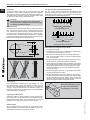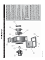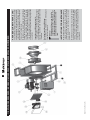
1
Radialventilatoren mit Stahlgehäuse Elektror Radialventilatoren Betriebs- und Montageanleitung Centrifugal fans made of steel DE Wentylatory promieniowe z korpusem stalowym Elektror centrifugal fans Operating and assembly instructions EN Instrukcja obsługi i konserwacji wentylatorów promieniowych PL Elektror airsystems sp. z o.o. ul. Leśna 38 PL-41-506 Chorzów Telefon +48 (0)32 277 65 60 Telefax +48 (0)32 277 65 61 [email protected] www.elektror.pl Betriebs- und Montageanleitung Radialventilatoren DE INHALT 2. ALLGEMEINES 2.1 Einleitung www.elektror.de Lieferbedingungen“. Diese stehen dem Betreiber spätestens seit Vertragsabschluß zur Verfügung. Gewährleistungs- und Haftungsansprüche bei Personen- und Sachschäden sind ausgeschlossen, wenn sie auf eine oder mehrere der folgenden Ursachen zurückzuführen sind: 2.2 Allgemeine Hinweise • Nicht bestimmungsgemäße Verwendung des Ventilators 2.3 Zusätzliche Hinweise • Unsachgemäßes Montieren, lnbetriebnehmen, Bedienen und Warten des Ventilator 3. SICHERHEIT 3.1 Allgemeine Hinweise zur Sicherheit 3.2 Hinweise zur Vermeidung und/oder Behebung von Problemen 3.3 Zusätzliche Sicherheitsregeln und Vorschriften zur Unfallverhütung. 4. EINSATZBEREICH, BESTIMMUNGSGEMÄSSE VERWENDUNG 5. TRANSPORT UND LAGERUNG 5.1 Lieferumfang 6. MONTAGE 6.1 Allgemeines 7. INBETRIEBNAHME 8. BETRIEB DER MASCHINE 9. INSTANDHALTUNG 9.1 Allgemeines 9.2 Wartung und Inspektion 9.3 Schmieren 9.4 Säubern 9.5 Wartung des Motors 9.6 Ersatzteilbestellung 10. ANHANG Konformitätserklärung 11. EXPLSIONSZEICHNUNG 12. ALLGEMEINE ERSATZTEILLISTE • Betreiben des Ventilators bei defekten Sicherheitseinrichtungen oder nicht ordnungsgemäß angebrachten oder nicht funktionsfähigen Sicherheits- und Schutzvorrichtungen • Nichtbeachten der Betriebsanleitungen die zu diesem Ventilator gehören. • Eigenmächtige bauliche Veränderungen am Ventilator • Eigenmächtiges Verändern der Leistungsdaten (z.B. Antriebsverhältnisse Leistung und Drehzahl) des Ventilators • Mangelhafte Überwachung von Ventilatorteilen, die einem Verschleiß unterliegen • Unsachgemäß durchgeführte Reparaturen • Katastrophenfälle durch Fremdkörpereinwirkung und höhere Gewalt 3 SICHERHEIT 3.1 ALLGEMEINE HINWEISE ZUR SICHERHEIT. Grundlegende Sicherheitshinweise Der Ventilator läuft bei seiner bestimmungsgemäßen Verwendung und bei einer regelmäßigen Reinigung der Laufrads störungsfrei und sicher. Bei Nichtbeachtung der notwendigen äußeren Bedingungen drohen jedoch Gefahren: • für Leib und Leben von Personen, die sich in der Nähe des Ventilators befinden • für den Ventilator und andere Sachwerte des Betreibers 2.1 EINLEITUNG 2 Alle Personen, die mit der Aufstellung, der Inbetriebnahme und der Wartung zu tun haben, müssen die nachfolgenden Hinweise aufmerksam lesen, verstehen und beachten. Es geht um Ihre Sicherheit! Diese Information ist in der Absicht geschrieben, von denen gelesen, verstanden und in allen Punkten beachtet zu werden, die für den Elektror Ventilator verantwortlich sind. Die komplette technische Information sollte stets in der Nähe des Ventilators aufbewahrt werden. Verpflichtung des Betreibers Der Betreiber verpflichtet sich, nur Personen an dem Ventilator arbeiten zu lassen, die Auf besonders wichtige Einzelheiten für den Einsatz des Elektror Ventilators wird in dieser Betriebsanleitung hingewiesen. • mit den grundlegenden Vorschriften über Arbeitssicherheit und Unfallverhütung vertraut und in die Handhabung des Ventilators eingewiesen sind 2.2 ALLGEMEINE HINWEISE Hinweise in der Betriebsanleitung beachten • das Sicherheitskapitel und die Warnhinweise in dieser Betriebsanleitung gelesen, verstanden und durch Ihre Unterschrift bestätigt. • Grundvoraussetzung für den sicherheitsgerechten Umgang und den störungsfreien Betrieb dieses Ventilators ist die Kenntnis der grundlegenden Sicherheitshinweise und der Sicherheitsvorschriften. • Das sicherheitsbewusste Arbeiten des Personals wird in regelmäßigen Abständen überprüft. • Diese Betriebsanleitung enthält die wichtigsten Hinweise, um den Ventilator sicherheitsgerecht zu betreiben. Verpflichtung des Personals Alle Personen, die mit Arbeiten an dem Ventilator beauftragt sind, verpflichten sich vor Arbeitsbeginn: • Diese Betriebsanleitung, insbesondere die Sicherheitshinweise, sind von allen Personen zu beachten, die an dem Ventilator arbeiten. • die grundlegenden Vorschriften über Arbeitssicherheit und Unfallverhütung zu beachten • Darüber hinaus sind die für den Einsatzort geltenden Regeln und Vorschriften zur Unfallverhütung zu beachten. • das Sicherheitskapitel und die Warnhinweise in dieser Betriebsanleitung zu lesen und durch ihre Unterschrift zu bestätigen, dass sie diese verstanden haben. 2.3 ZUSÄTZLICHE HINWEISE • Alle Sicherheits- und Gefahrenhinweise an der Maschine sind in lesbaren Zustand zu halten. Gewährleistung und Haftung Grundsätzlich gelten unsere „Allgemeinen Verkaufs- und Radial 01.14/10_GER_ENG_POL 2 ALLGEMEINES • für die effiziente Arbeit des Ventilators www.elektror.de Betriebs- und Montageanleitung Radialventilatoren 3.2 ZUSÄTZLICHE SICHERHEITSREGELN UND VORSCHRIFTEN ZUR UNFALLVERHÜTUNG IN DIESER ANLEITUNG SIND WIE FOLGT GEKENNZEICHNET Gefahr! Bezeichnet eine unmittelbar drohende Gefahr. Bei Nichtbeachtung können Tod oder schwerste Verletzungen die Folge sein. Vorsicht! Bezeichnet eine möglicherweise gefährliche Situation. Wenn Sie sie nicht meiden, können leichte oder geringfügige Verletzungen die Folge sein. Wichtig! Bezeichnet Anwendungstipps und andere besonders nützliche Informationen. 4 EINSATZBEREICH, BESTIMMUNGSGEMÄSSE VERWENDUNG Der Ventilator ist ausschließlich zum Fördern von Luft oder ähnlichen gasförmigen Gemischen bestimmt. Eine andere oder darüber hinausgehende Benutzung gilt als nicht bestimmungsgemäß. Für hieraus entstehende Schäden haftet die Firma Elektror nicht. Zur bestimmungsgemäßen Verwendung gehört auch: • das Beachten aller Hinweise aus der Betriebsanleitung und • die Einhaltung der Inspektions- und Wartungsarbeiten. Der Ventilator ist zur Förderung von Luft oder ähnlichen gasförmigen Gemischen ausgelegt. Dafür wird er zweckmäßiger Weise saug- und druckseitig an eine Rohrleitung angeschlossen. 5 TRANSPORT UND LAGERUNG Transport Der Ventilator wird komplett vormontiert geliefert. Nach Eintreffen des Ventilators sind evtl. Transportschäden umgehend festzustellen und beim Spediteur zu reklamieren. Hartes Aufsetzen beschädigt die Lagerung des Ventilators. Verladen Den Ventilator an seinen Transportösen mittig am Ventilatorgehäuse aufhängen (am Motor nur zum Balancieren). Die Aufhängung am Kran erst nach erfolgtem Befestigen entfernen. Gefahr! Nicht unter dem hängenden Ventilator stehen! Die Aufhängevorrichtung könnte reißen! Der herabstürzende Ventilator könnte Sie töten oder schwer verletzen! Radial 01.14/10_GER_ENG_POL Einlagern Einlagern des Ventilators im Freien sollte vermieden werden. Starke Korrosion kann die Lebensdauer des Ventilators reduzieren, die maximal zulässige Drehzahl herabsetzen. Unwucht des Laufrades könnte die Folge sein. Wasser kann in die Wälzlager eindringen und zu einem vorzeitigen Ableben führen. Deshalb sollte der Ventilator überdacht oder in Folie eingeschweißt gelagert werden. Bei längeren Stillstandszeiten alle zwei Wochen das Laufrad von Hand drehen. Nach Korrosionsschutzklasse 1 haben wir folgende max. zulässige Stillstandszeiten: • In geschlossen trockenen Räumen - max. 6 Monate • Im Freien, aber überdacht - max. 4 Monate • Im Freien nicht überdacht - max. 2 Monate • Sonstiger aggressiver Umgebung - auf Anfrage DE Bei Kupplugs- und Keilriemenantriebe soll diese Zeit wesentlich verkürzt werden, damit Probleme mit dem Fett, den Lagern und den Keilriemen vermieden werden. 5.1 LIEFERUMFANG Der Umfang der Lieferung ist beim Empfang anhand des Lieferscheins zu kontrollieren. Fehlende Teile sind sofort schriftlich bei Elektror zu melden. 6 MONTAGE (INKL. DEMONTAGE) 6.1 ANGABEN FÜR MONTAGE UND DEMONTAGE Aufstellung Der Ventilator wird serienmäßig- sofern nichts Besonderes vereinbart wurde – in RAL 5015 Pulverbeschichtet. Beim Aufstellen im Freien muss der Ventilator überdacht werden. Vorsicht beim Einbringen des Ventilators! Achten Sie auf Träger in Kopfhöhe! Sie könnten sich stoßen, verletzen. Der Ventilator muss so aufgestellt werden, daß genügend Platz für Wartungsarbeiten vorhanden ist. Es muss jederzeit die Möglichkeit bestehen mit geeignetem Hebewerkzeug schwere Teile des Ventilators zu transportieren (Gabelstapler, Kran). 7 INBETRIEBNAHME Gefahren bei falschem Anschluss Der Ventilator muss saug- und druckseitig gegen Hineingreifen und gegen Einsaugen von Fremdkörpern geschützt werden. Dieser Schutz ist zweckmäßigerweise eine lange Rohrleitung, die ein Erreichen des Laufrades verhindert, oder ein ausreichend engmaschiges Schutzgitter an einer Öffnung. Wird der Ventilator frei ansaugend oder ausblasend betrieben, so ist ein ausreichend engmaschiges Gitter zum Schutz vor Hineingreifen fest an dem Ein-/Austritt zu verschrauben. Der Ventilator muss auf seine mitgelieferten Schwingungsdämpfer montiert werden. Es ist auf einen sicheren Stand des Gerätes zu achten. Alle Auflagepunkte müssen absolut fest mit dem Untergrund verschraubt oder verschweißt sein. Die Verschraubung darf keine Stolperfalle sein. Gefahr! Kippelige Aufstellung kann zum Umstürzen des Ventilators führen. Der kippende Ventilator könnte Sie schwer verletzen! Achten Sie auf sicheren Stand. Inbetriebnahme Radialventilator Der Ventilator ist für den Eingebauten Zustand bei Betriebstemperatur ausgelegt. Beim Betreiben mit veränderten Betriebsverhältnissen ist folgendes zu beachten. Der Radialventilator läuft bei geschlossenem Ansaug oder Ausblas mit dem geringsten Anlaufstrom an. Bei kurz aufeinander folgendem Wiedereinschalten ist deshalb (wenn vorhanden) eine Klappe zu schließen um die Erwärmung des Motors so gering wie möglich zu halten. Besonders bei Ventilatoren die für den Dauerbetrieb bei höheren Temperaturen als die Anlauftemperatur ausgelegt sind, muss der Anlaufstrom geringstmöglich sein. Angaben zum Anlaufverhalten des Ven- 3 Betriebs- und Montageanleitung Radialventilatoren Gefahr! Den Ventilator erst einschalten, wenn ein Erreichen des Laufrades nicht mehr möglich ist! Der Ventilator saug- und druckseitig komplett angeschlossen und evtl. durch notwendige Schutzgitter gesichert ist. Probelauf des Radialventilators: • entfernen sie alle Fremdkörper wie (Werkzeuge, Kleintei-le, Schmutz usw.) aus dem Kanal. • Schutzgitter Montieren bei freiem Ansaug oder Ausblas. • Alle druck- und saugseitigen Anschlussteile müssen montiert sein • Das Laufrad darf am Gehäuse nicht streifen. 4 • Die Luftrichtung und Drehrichtung des Laufrades nach dem Typenschild prüfen. (Bei falscher Drehrichtung am Klemmenkasten Phasen tauschen). • Die Stromaufnahme des Motors prüfen. Mit dem Nennstrom des Motors vergleichen. • Vibrationen des Ventilators bei Betriebsdrehzahl unbedingt prüfen. Die gemessenenSchwingungen gem. VDI 2056 Gruppe T vergleichen. Unsere Laufräder sind nach ISO 1940 Gütestufe G 6,3 gewuchtet. • Bei Drehzahlgeregelten Ventilatoren bitte das gesamte Betriebsdrehzahlbereich durch Schwingungsmessung überprüfen, um eventuell vorhandene Resonanzstellen aufzufinden. • Betriebsdaten bei der Inbetriebnahme protokollieren. Elektrischer Anschluss Der elektrische Anschluss muss von einem ausgebildeten Elektriker durchgeführt werden. Die Betriebsschaltung ist dem Typenschild des Motors zu entnehmen. Der Motor darf nicht ohne Motorschutz betrieben werden. Eventuell vorhandene Thermistor / Thermokontakt -Motorschutzeinrichtungen müssen vor dem ersten Anlaufen in Betrieb sein! Es muss ein abschließbarer Schalter in der direkten Zuleitung zum Motor eingebaut werden, der im Falle einer Inspektion den Ventilator vom Netz trennt. L1 L2 L3 N Die drei Anfänge (U1, V1, W1) und die drei Enden (U2, V2, W2) der Wicklung sind an die sechs Klemmen im Klemmenkasten geführt. Dort werden die drei Hauptleiter (L1, L2, L3) immer mit den Stranganfängen verbunden. Schließt man die Strangenden (U2, V2, W2) zusammen, so ist der Motor in Stern (Y) geschaltet. Im Sternpunkt ist dabei die Summe der Spannungen und der Ströme gleich Null, der Phasenwiderstand liegt an Phasenspannung. Der Motorstrom entspricht dem Strom im Wicklungsstrang. Wird jeweils das Ende des einen Stranges mit dem Anfang des nächsten verbunden, so ist der Motor in Dreieck geschaltet. Der Phasenwiderstand liegt an der Netzspannung. Der Motorstrom ergibt sich aus der geometrischen Summe von zwei Phasenströmen (Bild 2). Diese Zusammenhänge machen verständlich, dass ein Motor sowohl in Y-Schaltung am 400 V-Netz, als auch in Dreieck-Schaltung am 230 V-Netz angeschlossen werden kann. Im Wicklungsstrang fließt in beiden Fällen etwa der gleiche Strom. Ähnliches gilt auch für die neuen Vorzugsspannungen 660 V (Y)und 380 V (Dreieck). Stimmt die alphabetische Aufeinanderfolge der Klemmenbezeichnungen (U1, V1, W1, U2, V2, W2) mit der zeitlichen Aufeinanderfolge der Phasen überein, so soll die Maschine Rechtslauf haben. Bei Linkslauf sind an der Maschine zwei äußere Anschlussleitungen zu vertauschen. Nach VDE 0530 muss im Klemmenkasten auch eine Anschlussklemme für den Schutzleiter vorhanden sein. Maschinen mit Nennleistung über 100 kW müssen zusätzlich eine Erdungsklemme am Gehäuse haben. Wicklungsausführung 220 V / 380 V direktes Einschalten bei Betriebsspannung 380 V 220 V W2 L1 U1 W1 L3 U1 U2 U2 V2 W2 U1 V1 U2 V1 L1 V2 L2 L2 V2 W1 L1 L2 L3 Dreieck-Schaltung W2 V1 L2 U2 V2 U1 V1 W1 L1 L2 L3 Y-Schaltung Radial 01.14/10_GER_ENG_POL Gefahr! Drehende Teile! Bei Lagern geschmiert mit Fett für hohe Temperaturen, kann es zu einer stärkeren Temperaturentwicklung in der ersten Stunde kommen, bis sich das Fett und die Lager eingelaufen haben. Fahren Sie den Ventilator langsam auf die Betriebsdrehzahl und achten Sie auf Schwingungen am Blocklager oder an den Stehlagern. In Deutschland beträgt die Netzfrequenz 50 Hz. Die Spannung zwischen zwei Hauptleitern (L1 L2 L3) ist die Leiterspannung UL (verkettete Spannung, Netzspannung). Die Spannung zwischen einem Hauptleiter und dem Mittelpunktsleiter ist die Sternspannung Uph (Phasenspannung). Dabei besteht der Zusammenhang UL = 1.73 x Uph. U Lesen Sie vor der Inbetriebnahme die Dokumentation zu Kupplung, Blocklager sowie zu den verwendeten Lagern und Fetten. Überprüfen Sie vor dem Start den Zustand des Fettes und der Lager insbesondere nach längerer Lagerung. Drehen Sie dabei manuell das Laufrad. Das Fett und die Lager sollen im einwandfreien Zustand sein, bevor der Ventilator elektrisch angeschlossen und gestartet wird. Überprüfen Sie den Zustand der Kupplung, insbesondere die optimale Flucht. Bitte beachten Sie hierzu die Herstellerangaben. Starten Sie den Ventilator bei niedriger Drehzahl und achten Sie auf das Verhalten der Kupplung und der Lager. Achten Sie auf Geräusche. Betriebsschaltung U Inbetriebnahme Radialventilator mit Kupplungsantrieb Die elektrische Zuleitung muss vor Beschädigung geschützt verlegt werden. Der Motor darf nicht über Nennstrom betrieben werden! U tilators finden Sie im Ventilatordatenblatt. Bei Motoren ohne Thermistormotorschutzeinrichtung muß zumindest die Oberflächentemperatur per Handauflegen kontrolliert werden. Lesen Sie bitte die Motordokumentation. UL UL DE www.elektror.de www.elektror.de Betriebs- und Montageanleitung Radialventilatoren 8 BETRIEB DER MASCHINE Der Ventilator darf nur von darin unterwiesenen Personen betrieben werden. Der Ventilator darf nur in Betrieb sein, wenn: • alle Sicherheitseinrichtungen und sicherheitsbedingte Überwachungseinrichtungen vorhanden und funktionsfähig sind. • sich niemand im Gefahrenbereich der Maschine aufhält • alle Kontrollöffnungen abgesichert und geschlossen sind Bei Funktionsstörungen ist der Ventilator sofort stillzusetzen und dieser Zustand zu sichern. Störungen umgehend beseitigen lassen! Gefahr! Der Ventilator darf bis zur maximalen Drehzahl nur bei nicht Überschreiten von max Temperatur betrieben werden! Das Laufrad kann bersten! Herausfliegende Teile können Sie töten, schwer verletzen! Die Laufradfestigkeit ist nur auf die maximalen Betriebsbedingungen laut Typenschild ausgelegt. 9 INSTANDHALTUNG 9.1 ALLGEMEINES Vorsicht! Bevor Sie Wartungs- oder Inspektionsarbeiten an diesem Ventilator ausführen, müssen Sie die Betriebsanleitung gelesen und verstanden haben. Umbauten Eigenmächtige Umbauten und Veränderungen des Ventilators sind aus Sicherheitsgründen verboten. Es muss vorher Rücksprache und schriftliche Bestätigung mit Elektror erfolgen. Gefahr! Der Ventilator muß vor Wartungsarbeiten vom Netz getrennt werden und gegen wiedereinschalten gesichert werden! Plötzliches Anlaufen des Ventilators könnte schwerste Verletzungen zur Folge haben. Vorsicht! Öle, Fette und sonstige Verunreinigungen können zum Sturz und damit zu Verletzungen führen. Der Bereich um den Ventilator muß vor Wartungsarbeiten sauber sein. Radial 01.14/10_GER_ENG_POL Gefahr! Beim Fördern von heißem Medium sind die außerhalb der Isolation liegenden Teile ebenso heiß wie das Medium selbst! Sie könnten sich verbrennen. Warten Sie mit den Arbeiten bis der Ventilator abgekühlt ist. Wichtig! Vergewissern Sie sich, ob Sicherheit für den zu wartenden Ventilator gegeben ist. Achten Sie auf gesunde Körperhaltung. Schwere Teile mit dem Kran heben. Wichtig! Sehr heiße und sehr kalte Arbeitsumgebung mindert die Konzentrationsfähigkeit. Achten Sie auf akustische und optische Warnsignale benachbarter Anlagenteile! 9.2 WARTUNG UND INSPEKTION Reinigen, Warten DE Der Ventilator muß regelmäßig inspiziert werden um evtl. Schäden rechtzeitig vor einen Totalausfall zu erkennen. Zur Wartung nur schutzisolierte Elektrogeräte verwenden! Wartungsarbeiten fallen an, wenn: • das Ventilatorlaufrad aufgrund von ungleichmäßiger Benutzung unwuchtig wurde, fremdartige feste Teile eingesaugt wurden, die am Laufrad oder Gehäuse Beschädigungen verursachten • Verschmutzungen von saug- oder druckseitigen Schutzgittem zu einem erhöhte Widerstand der Anlage führen • Verschmutzung an den Lüftungsgittern des Riemenschutzes keine Kühlung der Keilriemen gewähren • die Keilriemen rissig werden • die Keilriemen aufgrund der normalen Dehnung nachgespannt werden müssen • der Abrieb des elastischen Elementes der Kupplung auf Verschleiß schließen lässt • die Schwingungsdämpfer verrostet oder das Gummi beschädigt oder ermüdet ist • die Nachschmierfrist der Lager abgelaufen ist • erhöhte BCU-Werte an den Lagerstellen auf ein Ableben der Lager schließen lässt Lagerung (Stehlager oder Blocklager) Die Lagerung darf dauerhaft bei maximaler Belastung nur bis zu 125°C erwärmt werden! Die Lagerung muss ausreichend geschmiert sein. Ungenügende Schmierung führt zum vorzeitigen Ableben der Lager. Dauergeschmierte Lager (ohne Nachschmiermöglichkeit) müssen nach 10.000 Betriebsstunden ausgebaut, gereinigt und neu gefettet werden (siehe Anleitungen der Lagerhersteller). Alle Lager in Elektror-Ventilatoren sind auf eine Lebensdauer von mindestens 40.000 Betriebsstunden ausgelegt. Schmiervorschrift auf dem Schmierschild / Motordokumentation beachten! Alle Lager sollten regelmäßig auf geräuscharmen Lauf und Dichtigkeit kontrolliert werden. Vorsicht! Die Lagerung hat eine Betriebstemperatur bis ca. 80°C . Sie können sich verbrennen. Nicht unachtsam an das Lagergehäuse fassen. Gefahr! Starke Vibration am Laufrad kann zu Dauerbruch führen! Das Laufrad kann bersten! Herausfliegende Teile können Sie töten, schwer verletzen! Ventilator regelmäßig auf Schwingungen prüfen und wenn nötig, Reinigung des Laufrades durchführen. Beim Fördern von abrassiven oder ätzenden Medien ist bei Feststellung von Materialschwund Ersatz zu schaffen. Regelmäßige Inspektion ist unerlässlich. Gefahr! Materialschwund führt zum Verlust der Festigkeit. Das Laufrad kann bersten. Herausfliegende Teile können Sie töten, schwer verletzen. Bei Materialschwund Ersatzlaufrad einbauen! Begutachten Sie das Laufrad in regelmäßigen Abständen um eine Veränderung feststellen zu können. -> Öffnen Sie die Reinigungsluke -> Dampfen Sie das Laufrad ab. 5 Betriebs- und Montageanleitung Radialventilatoren DE www.elektror.de Keilriemen Das Spannen der Schmalkeilriementriebe Die Riemen müssen stets nach Vorschrift gespannt sein. Die technischen Daten hierfür entnehmen Sie dem Ventilatordatenblatt. Die Riemen müssen vor drohendem Reißen gewechselt werden, und zwar Immer der komplette Satz, damit die Spannung aller Riemen gewährleistet ist. Nur die richtige Riemenvorspannung gewährleistet eine optimale Lebensdauer der Riemen und den bestmöglichen Wirkungsgrad des Antriebes. Wir empfehlen die Benutzung eines Riemenvorspannkraft-Messgerätes. Vorsicht! Beim Wechseln der Riemen! Sie könnten Ihre Finger quetschen. Befolgen Sie die Anweisungen der Anleitung Riemenwechsel. 10 20 30 40 50 60 Riemenwechsel Durchbiegung in mm Entspannen Sie den Riementrieb durch Annähern der Scheiben. Die Riemen nicht mit einem Schraubendreher aushebeln . Neuen Satz Riemen einlegen. Riementrieb ausrichten und nach unseren Empfehlungen spannen. Nach 30 Minuten Betrieb unter Last Riemenspannung prüfen und gegebenenfalls nachstellen. Während der ganzen Lebensdauer des Riementriebs entfällt jegliche Wartungsarbeit. 14 12 E1 10 8 6 4 2 Durchbiegungskraft Riemenspannkraft - Messgerät Bestimmung der Riemenvorspannkraft: 1. Achsabstand messen. E1 A 2. Achsabstand in Meter mit 16 multiplizieren. Das Produkt gibt die Riemendurchbiegung in mm an. 3. Die Riemendurchbiegung wird auf dem Messgerät mit dem unteren Markierungsring auf der Durchbiegungsskala in mm eingestellt. 4. Der obere Markierungsring wird gegen Ende des Rohres auf der Skala für Durchbiegungskraft positioniert. 5. In der Mitte des Achsabstandes rechtwinklig zum Riemen wird das Messgerät platziert. Danach wird mittels Druck auf die obere Hülse der Riemen durchgedrückt. Es wird soviel Kraft aufgewendet, dass die markierte Durchbiegung erreicht wird. 6. Die Durchbiegekraft kann nun in der Position des Markierungsringes abgelesen werden. 6 FALSCH FALSCH RICHTIG 7. Die Durchbiegekraft wird mit den Werten in der Tabelle verglichen. Bei neuen Antrieben sollten die höheren Werte für die Anlaufphase gewählt werden. Nach 30 Min. Betriebszeit unter Last sollte die Durchbiegekraft erneut geprüft und gegebenenfalls nachgestellt werden. Ausrichtung Eine einwandfreie Ausrichtung ist sehr wichtig, da sonst die Riemenflanken schnell verschleißen. Riemen nicht mit Gewalt durch Schraubendreher oder drgl. in die Rillen einzwingen. Auf gutes Seitenfluchten der Scheiben achten. Regelmäßige Überprüfung der Riemenspannung gewährleistet hohe Lebensdauer der Riemen. A Riemendurchbiegung 16 mm je 1000 mm Achsabstand, rechtwinklig zur Achsmitte P Lagerung von Keilriemen Riemenschutz Wo ein Riemenschutz erforderlich ist, sollte eine Schutzgitterkonstruktion wegen der besseren Belüftung einer geschlossenen Ausführung vorgezogen weiden. Radial 01.14/10_GER_ENG_POL Keilriemen sollten in einem trockenen Raum gelagert werden. Sie müssen vor Hitzeeinwirkung und direktem Sonneneinfall geschützt sein. Wenn möglich sollten sie frei hängend gelagert und auf keinen Fall eng verschnürt werden. www.elektror.de Betriebs- und Montageanleitung Radialventilatoren Kraftachsabstand für 16 mm Durchbiegung xxx Profil Wirkdurchmesser der kleinen Scheibe [mm] Newton [N] Schmiertabelle für Blocklager: Lagertyp Betriebsstunden Fettmenge je Lager URETHYN E2 GLEITMO 591 BLW 30 1.500 Std. 1.750 Std. 5g 25 bis 35 BLW 40 1.250 Std. 1.750 Std. 10 g 140 bis 200 35 bis 45 BLW 50 1.200 Std. 1.450 Std. 10 g 160 bis 224 45 bis 65 BLW 60 1.200 Std. 1.450 Std. 15 g 236 bis 315 65 bis 85 BLW 75 1.000 Std. 1.250 Std. 20 g 224 bis 355 85 bis 110 375 bis 560 115 bis 150 Z 56 bis 100 5 bis 7,5 A 80 bis 140 10 bis 15 B 125 bis 200 20 bis 30 C 200 bis 400 40 bis 60 SPZ SPA SPB SPC 67 bis 95 13 bis 20 100 bis 140 20 bis 25 100 bis 132 xxx | Riemenvorspannkraft - Meßgerät wird in der Mitte Achsabstandes rechtwinklig zum Riemen angebracht Kupplung Das elastische Element der Kupplung muss vor restlosem Verschleiß erneuert werden. In der Regel muss dazu der Motor beiseite geschoben werden. Beim heranführen der beiden Kupplungshälften - Motor und Lager - ist auf optimale Flucht zu achten. Vorsicht! Kupplungen dürfen nur von geschultem Fachpersonal ausgetauscht werden. Immer Originalersatzteile verwenden. Vorsicht! Kupplungsabrieb nicht mit Druckluft entfernen! Der Staub könnte in ihre Augen geraten. Kupplungsabrieb mit Besen entfernen. DE 9.4 SÄUBERN Laufradwartung Schmutzige Fördermedien können das Laufrad ungleichmäßig benetzen und dadurch zu Unwucht führen. Die Schwingungen, an der Lagerung abgenommen, dürfen dauerhaft nicht über 8 mm/s liegen. Das Laufrad muss dann z.B. mit einem Dampfstrahler gereinigt werden. 9.5 WARTUNG DES MOTORS Die Motoren bis BG 200 haben Lager mit Dauerschmierung. Es wird empfohlen alle 2Jahre diese Lager zu reinigen, oder durch neue zu ersetzen. Motoren ab BG 225 haben eine Nachschmiereinrichtungen (hierzu Betriebsanleitung des Motorherstellers beachten). 9.6 ERSATZTEILBESTELLUNG Bitte immer nach Auftragsnummer oder Typenschild bestellen. Nicht von uns gelieferte Ersatzteile sind von uns nicht freigegeben. Für Schaden, die durch die Verwendung von solchen Teilen entstehen, ist jegliche Haftung des Herstellers ausgeschlossen. 9.3 SCHMIEREN Radial 01.14/10_GER_ENG_POL Vorsicht! Nachschmierbare Wälzlager müssen nach erste Betriebsstunde mit 3-fache Fettmenge wie auf dem Schmierschild nachgeschmiert werden. Nach 24 Betriebsstunden nachmals mit 1-fache Fettmenge. Eine Lagerung mit Fettschmierung kann auch während des Betriebs nachgeschmiert werden. Bei einem Lagerwechsel empfehlen wir den Austausch der gesamten Lagereinheit. Sie erhalten dann die überholte Einheit für Ihr Ersatzteillager zurück. 7 Betriebs- und Montageanleitung Radialventilatoren DE www.elektror.de 10 ANHANG Einbauerklärung nach Anhang IIB Elektror airsystems Sp. z o.o. ul. Leśna 38 PL-41-506 Chorzów Wir erklären in alleiniger Verantwortung, dass das Produkt, auf das sich diese Erklärung bezieht, mit den unten aufgeführten Normen oder normativen Dokumenten übereinstimmt. Bei einer nicht mit uns abgestimmten Änderung der Maschinen verliert diese Erklärung ihre Gültigkeit. Bezeichnung der Maschinen: Radialventilatoren CFL, CFM, CFH, CFXH, CFXXH, CFMT, CFR, PFL, PFM, PFH, CFP Einschlägige EC Richtline, denen das Produkt entspricht: EG – Maschinenrichtlinie 2006/42/EG EG – Elektrische Betriebsmittelrichtlinie 2006/95/EG Fundstellen der harmonisierten Normen: DIN EN ISO 12100 Sicherheit von Maschinen EN 60204-1 Sicherheit von Maschinen, elektrische Ausrüstung von Maschinen, Allgemeine Anforderungen (Elektromotoren) DIN EN 60034-1 Drehende elektrische Maschinen, Teil 1: Bemessung und Betriebsverhalten DIN EN 60034-5 Drehende elektrische Maschinen, Teil 5: Schutzarten aufgrund der Gesamtkonstruktion von elektrischen Maschinen DIN EN 60664-1 Isolationskoordination für elektrische Betriebsmittel in Niederspannungsanlagen, Teil 1: Grundsätze, Anforderungen und Prüfungen Angewandte nationale Normen und techn. Spezifikationen, inbesondere: DIN 24163, DIN VDE 0110-1 Die Inbetriebnahme des Maschinenteils ist so lange untersagt, bis nach Einbau in die Hauptmaschine, bzw. nach Anbringen der notwendigen Sicherheitsvorkehrungen alle Anforderungen der EG-Maschinenrichtlinie bezüglich Sicherheit uns Gesundheit erfüllt sind Kreher (Geschäftsführer) Chorzów, 01.07.2012 Radial 01.14/10_GER_ENG_POL 8 www.elektror.com Operating and assembly instructions centrifugal fans CONTENT 2. GENERAL 2.1 Introduction 2.2 General advice 2.3 Additional advice 3. SAFETY 3.1 General advice about safety 3.2 Advice on avoiding and/or remedying problems 3.3 Additional safety rules and regulations for accident prevention. • Installation, commissioning, operation or servicing of the ventilator not performed properly • Operation of the ventilator when the safety or protective devices are faulty, not working properly or not fitted properly • Unauthorised constructional modifications to the ventilator • Unauthorised alteration of the performance data (e.g. drive ratios, performance and rotational speed) of the ventilator • Deficient monitoring of ventilator parts that are subject to wear 5. TRANSPORTATION AND STORAGE 5.1 Scope of supply • Repairs not performed properly 7. PUTTING INTO SERVICE 8. OPERATING OF THE FAN 9. SERVICING 9.1 General • Catastrophic events due to the effect of a foreign body or an act of God 3 SAFETY 3.1 GENERAL ADVICE ON SAFETY 9.4 Cleaning Basic safety instructions The ventilator will run troublefree and safely if it is used as intended and the impeller is cleaned regularly. But if the specified external conditions are not observed, there is a risk: 9.5 Servicing the motor • to life and limb of persons who are near to the ventilator 9.6 Ordering spare parts • to the ventilator and other material assets of the owner 9.2 Maintenance and Inspection 9.3 Lubrication 10. ANNEX Declaration of conformity • to the efficient working of the ventilator 11. BROKEN VIEW DRAWING All persons who are involved in installation, commissioning and maintenance, must attentively read, understand and observe the following advice. Your safety depends on it! 12. GENERAL SPARE PART LIST 2 GENERAL 2.1 INTRODUCTION This information is written for the purpose of being read, understood and observed in all points by those responsible for the Elektror vcventilator. The complete technical information should always be kept in safe place close to the ventilator. This operating manual points out particularly important details about using the Elektror ventilator. 2.2 GENERAL ADVICE Adhere to the advice given in this operating manual. • The basic precondition for troublefree operation of this ventilator and handling in accordance with safe practice, is a knowledge of the basic safety rules and regulations. • This operating manual contains the essential advice for operating the ventilator in a safe manner. • This operating manual, and especially the safety instructions, are to be observed by all persons who work on the ventilator. • On top of this, the accident-prevention rules and regulations that apply at the installation site are to be observed. 2.3 ADDITIONAL ADVICE Warranty and liability As a basic principle our “General Terms and Conditions of Supply” shall apply. These shall be available to the owner at the latest when the contract is concluded. Claims under warranty or for liability in relation to persons or material damage shall be excluded if they are attributable to one or more of the following causes: EN • Non-adherence to the operating instructions that belong to this ventilator 4. FIELD OF USE 6. INSTALLATION 6.1 General Radial 01.14/10_GER_ENG_POL • Use of the ventilator other than as intended. Obligation of the owner The owner undertakes to allow only such persons to work on the ventilator, who • are familiar with the basic occupational safety and accident prevention regulations and have received instruction in working on and using with the ventilator • have read and understood the safety chapter and warning instructions in this manual, and confirmed this by their signature. • Checks shall be performed at regular intervals to ensure personnel are working in a safety-conscious way. Obligation of personnel Before starting work on the ventilator, all persons so assigned undertake to: • observe the basic regulations about occupational safety and accident prevention • have read and understood the safety chapter and warning instructions in this manual, and confirmed this by their signature • All safety and danger signs on the machine must be maintained in legible condition. 3.2 ADDITIONAL SAFETY RULES AND REGULATIONS FOR ACCIDENT PREVENTION ARE INDICATED IN THIS MANUAL AS FOLLOWS Danger! Indicates an immediate threat of danger that could cause severe injury, or even death, if instructions are not followed. 9 Operating and assembly instructions centrifugal fans EN Important! Describes tips on usage and other particularly useful information. 4 FIELD OF USE The ventilator is intended solely for conveying air or similar gaseous mixes. Any other use beyond this is not as intended. The firm of Elektror is not liable for loss or injury arising from such use. Use as intended also necessarily includes: • observance of all instructions in the operating manual and • adherence to the inspection and maintenance work The ventilator is designed to convey air or similar gaseous mixes. For this it is appropriate to be connected to tubing on both the pressure and suction side. 5 TRANSPORT AND STORAGE Transport The ventilator is supplied fully pre-assembled. Upon receipt of the ventilator, any damage during transit must be ascertained immediately and a claim made against the shipping agent. Setting down with a jolt can damage the ventilator‘s bearing. Loading Suspend the ventilator by its transport eyes at the middle of its housing (on the motor only for balancing). Remove the suspension from the crane only after properly secured. Danger! Do not stand beneath the suspended ventilator! The suspension device could break! The falling ventilator could kill or severely injure you! 10 6 INSTALLATION (INCL. DISMANTLING) 6.1 INSTALLATION AND DISMANTLING INFORMATION Installing Unless specially agreed otherwise, as standard the ventilator is supplied with a RAL 5015 powder-coated finish. If installed outdoors, a cover must be fitted over the ventilator. Caution! Take care when putting the ventilator in place! Watch out for beams at head height! You might bang your head or injure yourself. The ventilator must be installed with enough room to allow maintenance work. It has to be possible at all times to transport heavy parts of the ventilator with suitable lifting tackle (fork-lift or crane). 7 PUTTING INTO SERVICE Dangers of incorrect fitting On both the suction and pressure sides the ventilator must be protected against foreign bodies being sucked in or penetrating it. A suitable means of protection for this is long tubing that prevents objects reaching the impeller or a sufficiently close-mesh grille over the openings. If the ventilator is operated with free intake or outlet, a sufficiently close-mesh grille to prevent penetration must be screwed onto the inlet/outlet. The ventilator must be mounted on its vibration dampers included in the delivery. The unit must have a solid footing. All points of support must be screwed or welded absolutely solidly to the foundation. The screwed connections must not be a trip hazard. Danger! Wobbly installation may result in the ventilator falling over. A ventilator that falls over could injure you severely! Make sure the mounting is solid. Storing Commissioning the centrifugal fan Storing the ventilator outdoors should be avoided. Severe corrosion can shorten the ventilator‘s service life and lower its maximum permitted speed. An out-of-balance impeller might be the result. Water may penetrate the roller bearings and cause their premature failure. The ventilator should therefore be stored under cover or sealed up in film. The ventilator is designed for built-in operation at working temperature. The following must be observed when operating under different operating conditions. When the air inlet or outlet is closed, the radial ventilator starts up with the lowest starting current. Therefore, when repeatedly switched on with little interval, a flap (if fitted) should be closed to keep heating of the motor as low as possible. The starting current must be as low as possible especially in the case of ventilators designed for continuous operation at higher temperatures then the starting temperature. Details of the ventilator‘s starting characteristics can be found in the respective data sheet. For motors without thermistor motor protection, the surface temperature must be checked at least by placing the hand on it. Please read the documentation for the motor. If the ventilator is at a standstill for a lengthy period, turn the impeller by hand every two weeks. According to corrosion protection class 1 the following max. permitted standstill periods apply: • In closed dry rooms - max. 6 months • Outdoors, but covered over - max. 4 months • Outdoors, not covered over - max. 2 months • Other aggressive environments - figures on request For clutch and V-belt drives this time should be considerably shortened, so that any problems with the grease, the bearings and the belt can be avoided. Danger! Only switch on the ventilator when the impeller is no longer exposed! On both the suction and pressure sides the ventilator must be fully attached, with protective grille fitted if appropriate. 5.1 SCOPE OF SUPPLY Upon delivery the parts supplied should be checked against the delivery note for completeness. Any missing parts should be reported to Elektror in writing straight away. Commissioning centrifugal fan with clutch drive Before operating, read the documentation for coupling, bearing block and the bearing and grease used. Before starting , check the condition of the grease and the bearings especially after prolonged storage. For this turn manually the impeller. The grease and the bearings should be in perfect Radial 01.14/10_GER_ENG_POL Caution! Indicates a potential hazard that may cause severe injury if instructions are not followed. www.elektror.com Operating and assembly instructions centrifugal fans Danger! Only switch on the ventilator when the impeller is no longer exposed! On both the suction and pressure sides the ventilator must be fully attached, with protective grille fitted if appropriate. Test run of the radial ventilator: • Clear the duct of all foreign bodies, such as tools, small accessories or dirt etc. • Fit a safety grille in the case of free intake or outlet. • All of the pressure and suction side attachments must be fitted. • The impeller must not brush against the housing. • Check that the air direction and impeller‘s direction of rotation match the rating plate. (swap the phases at the terminal box if wrong direction of rotation). • Check the current drawn by the motor. Compare this against the motor‘s nominal current. • Without fail check for vibration of the ventilator at its working speed. Compare the measured vibrations with VDI 2056 group T. Our impellers are balanced according to ISO 1940 quality level G 6.3. • In the case of speed-regulated ventilators, please perform vibration measurement for the entire operating speed range to find any points of resonance. • Make a log of the operating data during commissioning. Electrical connection The electrical connection must be set up by a trained electrician. The service connection can be gathered from the motor‘s rating plate. The motor must not be operated without motor protection. Any existing thermistor / thermal contact motor protection devices must be in service before the initial start-up! A lockable switch must be fitted in the direct supply line to the motor, so that the ventilator can be isolated from the mains when an inspection is carried out. The electrical supply line must be laid with protection against it being damaged. The motor must not be operated above nominal current! Radial 01.14/10_GER_ENG_POL Service connection The mains frequency in Germany is 50 Hz. The voltage between two main conductors (L1L2L3) is the line-to-line voltage UL (voltage between phases, mains voltage). The voltage between a main conductor and the centre conductor is the star voltage Uph (phase voltage). Here the following relation exists: UL = 1.73 x Uph. U L2 L3 U Danger - rotating parts ! For bearings lubricated with grease for high temperatures, it can lead to a increased temperature development in the first hour, until the grease and the bearings have been run in. Drive the fan slowly to the operating speed and watch out for the vibrations at the bearing block or at the pedestal bearings. L1 EN U condition before the fan is electrically connected and started. Check the condition of the clutch, especially the optimal flight. Please refer to the manufacturer’s instructions. Start the fan at low speed and pay attention to the behaviour of the clutch and the bearings. Pay special attention for unusual noises. UL UL www.elektror.com N The three winding starts (U1, V1, W1) and winding ends (U2, V2, W2) are fed to the six terminals in the terminal box. There, the three main conductors (L1, L2, L3) are always connected to the phase winding starts. If the phase ends are joined together (U2, V2, W2), then the motor is connected in star (Y). At the star point, the sum of the voltages and currents is equal to zero, and here the phase resistance lies on the phase voltage. The motor current corresponds to the current in the winding phase. If the end of each phase is joined to the start of the next, then the motor is connected in delta. The phase resistance lies on the mains voltage. The motor current derives from the geometric sum of two phase currents (Figure 2) These relationships make it clear that a motor can be connected both in Y-connection (star) on the 400 V supply and in delta-connection on the 230 V supply. Approximately the same current flows in the winding phase in both cases. A similar situation also applies for the new preferred voltages of 690 V (Y) and 400 V (delta). If the alphabetic sequence of the terminal designations (U1, V1, W1, U2, V2, W2) matches the temporal sequence of the phases, the machine should rotate clockwise. With anti-clockwise rotation, to external connecting leads on the machine must be swapped. According to VDE 0530 the terminal box must also have a connecting terminal for the protective conductor. Machines with a nominal power that exceeds 100 kW must also have an earth terminal on the housing. Winding designs 220 V / 380 V direct power supply at operating voltage 380 V 220 V W2 L1 U1 U1 L1 11 W1 L3 U2 U2 V2 W2 U1 V1 U2 V1 V2 L2 L2 V2 W1 L1 L2 L3 Δ-configuration W2 V1 L2 U2 V2 U1 V1 W1 L1 L2 L3 Y-configuration 8 OPERATING THE VENTILATOR The ventilator must be operated only by persons trained in how to use it. The ventilator may only be used when: • all safety devices and safety-critical monitoring devices are fitted and working. • nobody is in the danger area of the machine • all inspection holes are safe and closed. If the ventilator is not working properly, it must be stopped straight away and secured in this state. Get the fault rectified straight away! Operating and assembly instructions centrifugal fans 9 SERVICING 9.1 GENERAL Caution! Before performing maintenance or inspection work on this ventilator, you need to have read and understood the operating manual. Modifications Unauthorised modifications to the ventilator are forbidden for safety reasons. Elektror must be consulted and written approval obtained before making any alterations. Danger! The ventilator must be disconnected from the mains supply, and safeguarded against being switched on again, before performing maintenance work! Severe injuries could result if the ventilator were to suddenly start up. Caution! Oils, grease and other contaminants can cause falls with resulting injuries. The area around the ventilator must be clean before work is started. Danger! When a hot medium is conveyed, those parts that lie outside of the insulation are just a shot as the medium itself! You could suffer burns. Delay starting work until the ventilator has cooled down. Important! Make sure that the ventilator to be serviced is safe. Maintain good posture when working. Use a crane to lift heavy parts. 12 Important! The ability to concentrate is reduced when the working environment is very hot or very cold. Watch out for audible or visual warning signs from adjoining parts of the equipment! 9.2 MAINTENANCE AND INSPECTION Cleaning, Maintenance The ventilator must be regularly inspected to detect any damage long before total failure. Use only totally insulated electrical equipment for maintenance! Maintenance work is due if: • the ventilator impeller has become unbalanced due to irregular usage • foreign bodies have been sucked in and caused damage to the impeller or housing • dirt on the pressure- or suction side safety grille is causing increased resistance to the air flow • dirt on the venting grilles of the belt guard is not allowing cooling of the V-belts • the V-belts need retensioning as a result of normal elongation • abrasion of the elastic element of the coupling suggests wear • the vibration dampers are rusty or the rubber is damaged or fatigued • relubrication of the bearings is overdue • increased BCU values on the bearings indicate their demise Bearing (pedestal or block bearing) The bearing must be heated up permanently to no more than 125°C at maximum loading! The bearing must be adequately lubricated. Inadequate lubrication leads to premature failure of the bearing. Permanently lubricated bearings (without any possibility of relubrication ) must be removed, cleaned and re-greased after 10,000 operation hours (see bearing manufacturer‘s instructions). All bearings in Elektror ventilators are designed for a service life of at least 20,000 operating hours. Observe the lubrication instruction on the lubrication plate/ motor documentation! All bearings should be checked regularly for low-noise running and a tight seal. Caution! The bearing has a working temperature of up to ca. 80°C .You may burn yourself. Do not grasp the bearing housing without caution. Danger! Severe vibration of the impeller can lead to endurance fracture! The impeller can fly asunder! Parts flying out could kill or severely injure you! Check the ventilator regularly for vibration and, if necessary, clean the impeller. Where abrasive or corrosive media is being conveyed and a loss of material is detected, a replacement part must be obtained. Regular inspection is essential. Danger! Loss of material leads to loss of strength. The impeller can fly asunder! Parts flying out could kill or severely injure you! If the impeller has lost material, fit a new one! Assess the impeller at regular intervals to determine any changes. -> Open the cleaning hatch -> Steam off the impeller V-belts The belts must always be tensioned as directed. Refer to the ventilator‘s data sheet for the relevant specifications. The belts must always be replaced as a complete set to ensure all belts are tensioned, long before there is any threat of snapping. Caution When changing the belts! You could crush your fingers. Follow the instructions in the belt changing guide. Replacing belts Release the belt drive by bringing the pulleys closer. Do not prise out the belts using a screwdriver. Insert a new set of belts. Align the belt drive and tension according to our recommendations. After 30 minutes of operation under load, check the belt tension and re-adjust, if necessary. No maintenance of any kind is required during the entire service life of the belt drive. Radial 01.14/10_GER_ENG_POL EN Danger! The ventilator may be operated up to maximum speed only if the maximum temperature is not exceeded! The impeller can fly asunder! Parts flying out could kill or severely injure you! The impeller strength rating is only up to the maximum operating conditions as indicated on the rating plate. www.elektror.com www.elektror.com Operating and assembly instructions centrifugal fans Determining the belt initial tension force: E1 1. Measure the shaft spacing. 2. Multiply the shaft spacing in metres by 16. The product gives the belt deflection in mm. 3. On the measuring device, the belt deflection is adjusted with the lower marking ring on the deflection scale in mm. E1 A EN 4. The upper marking ring is positioned towards the end of the tube on the scale for deflection force. 5. The measuring device is placed at the midpoint of the shaft spacing at right angles to the belt. The belt is then deflected by pressing on the upper sleeve. Sufficient force is applied to reach the marked deflection. 6. The deflection force can then be read off at the position of the marking ring. 7. The deflection force is compared against the values in the table. With new drives the higher values should be chosen for the start-up phase. After 30 minutes of operation under load, the deflection force should be checked again and readjusted if necessary. A FALSE FALSE CORRECT P Belt deflection 16 mm per 1.000 mm center distance, rectangular to the mid of the axle. Alignment Perfect alignment is very important, otherwise the belt flanks wear very quickly. Do not use a screwdriver or similar tool to force the belt into the groove. Make sure the pulleys are well aligned laterally. Regular checking of the belt tension ensures belts have a long service life. Center distance for 16 mm deflection xxx Profile Storage of V-belts V-belts should be stored in a dry room. They must be protected from the effects of heat and direct exposure to sunlight. They should be stored freely suspended, if possible, and under no circumstances tied up tightly. SPZ SPA Belt guard Where a belt guard is necessary, a protective grill is preferable to a closed design, because of its better ventilation. SPB Tensioning the narrow V-belt drive SPC Only the correct initial belt tension guarantees an optimum belt service life and the best possible degree of drive efficiency. We recommend the use of a belt initial tension measuring device. 10 20 30 40 50 Effective diameter of the disk [mm] Newton [N] 67 up to 95 13 up to 20 100 up to 140 20 up to 25 100 up to 132 25 up to 35 140 up to 200 35 up to 45 160 up to 224 45 up to 65 236 up to 315 65 up to 85 224 up to 355 85 up to 110 375 up to 560 115 up to 150 Z 56 up to 100 5 up to 7,5 A 80 up to 140 10 up to 15 B 125 up to 200 20 up to 30 C 200 up to 400 40 up to 60 xxx| belt preload force - Measuring instrument is mounted in the center spacing perpendicular to the belt 60 Coupling The elastic element of the coupling must be replaced before it is totally worn. The motor normally has to be pushed to one side for this. Optimal alignment must be ensured when bringing together the two halves of the coupling - motor and bearing. Radial 01.14/10_GER_ENG_POL Deflection in mm 14 12 10 8 6 4 2 Deflection force Belt initial tension measuring device Caution! Couplings must only be replaced by trained specialists. Always use original replacement parts. 13 Operating and assembly instructions centrifugal fans EN Caution! Do not use compressed air to remove abraded coupling! The dust could get in your eyes. Remove abraded coupling dust with a brush. 9.3 LUBRICATION Caution! After the initial operating hours, regreaseable roller bearings must be regreased with triple the amount of grease as on the lubrication plate. After 24 hours of operation, repeat with the single amount of grease. A bearing with grease lubrication can also be regreased during operation. If the bearing needs changing, we recommend replacing the entire unit. You will then receive the overhauled unit back for your spare parts store. Operating hours 9.4 CLEANING Impeller Soiled conveying media may wet the impeller unevenly and thereby lead to imbalance. The oscillations picked up at the bearing must not permanently exceed 8 mm/s. In this case the impeller must be cleaned with a steam jet, for example. 9.5 SERVICING THE MOTOR Motors up to BG 200 have bearings of the permanentlygreased type. It is recommended that these bearings are cleaned or replaced every 2 years. Motors from BG 225 onwards have a regreasing device (refer to the motor manufacturer‘s operating instructions about this). 9.6 ORDERING SPARE PARTS Please always order according to order number or rating plate. Lubrication table for block bearings: Bearing type www.elektror.com Qty grease per bearing URETHYN E2 GLEITMO 591 BLW 30 1.500 hrs 1.750 hrs 5g BLW 40 1.250 hrs 1.750 hrs 10 g BLW 50 1.200 hrs 1.450 hrs 10 g BLW 60 1.200 hrs 1.450 hrs 15 g BLW 75 1.000 hrs 1.250 hrs 20 g Replacement parts not supplied by us are unapproved by us. The manufacturer excludes all liability for loss or injury arising from the use of such parts. Radial 01.14/10_GER_ENG_POL 14 www.elektror.com Operating and assembly instructions centrifugal fans 10 ANNEX Declaration of installation conformity pursuant to annex IIB Elektror airsystems Sp. z o.o. ul. Leśna 38 PL-41-506 Chorzów EN We herewith declare that the machines named In the following were designer and manufactured by us in compliance with the rules and regulations of the below EG Directives. If a changing of the machines is not coordinated with us this declaration is not valid. Designation of machines: Radial fans - types CFL, CFM, CFH. CFXH, CFXXH, CFMT, CFR, PFL, PFM, PFH, CFP, CFD Relevant EG Directives: EG – Low Voltage Directive 2006/95/EG EG – Machinery Directive 2006/42/EG Applied harmonized standards: DIN EN ISO 12100 Security of machines DIN EN 60034-1 Rotating electrical machines; Part 1 Rating and performance DIN EN 60034-5 Rotating electrical machines; Part 5 Degrees pf protection provided by integral design of rotating electrical machines DIN EN 60664-1 Insulation co-ordination for equipment within low-voltage systems DIN EN 60204-1 Security of machines, electrical equipment of machines, general requirements (Electrical motors) DIN EN 1127-1, EN 13463-5, EN 14986:2007 Applied national standards and technical specifications: DIN 24163, DIN VDE 0110-1 Commissioning is prohibited until the conformity of the final product has been determined with the rules and regulations of the Directive 98/37 EG. Kreher (Managing Director) Chorzów, 01.07.2012 Radial 01.14/10_GER_ENG_POL 15 Instrukcja obsługi i konserwacji wentylatorów promieniowych 2. OGÓLNE 2.1 Wstęp 2.2 Ogólne wskazówki 2.3 Dodatkowe wskazówki PL 3. BEZPIECZEŃSTWO 3.1 Ogólne wskazówki bezpieczeństwa 3.2 Wskazówki dotyczące unikania i/lub usuwania problemów 3.3 Dodatkowe przepisy BHP 4. ZAKRES STOSOWANIA, ZGODNOŚĆ Z PRZEZNACZENIEM, ZASTOSOWANIE 5. TRANSPORT I PRZECHOWYWANIE 6. MONTAŻ 6.1 Ogólne 7. URUCHOMIENIE 8. PRACA MASZYNY 9. UTRZYMANIE W RUCHU 9.1 Zasady ogólne 9.2 Konserwacja i inspekcja 9.3 Smarowanie łożyskowania 9.4 Czyszczenie 9.5 Serwisowania silnika 9.6 Zamawianie części zamiennych 10. ZAŁĄCZNIK Potwierdzenie zgodności 11. RYSUNEK ZESPOŁU ROZŁOŻONEGO 12. WYKAZ CZĘŚCI ZAMIENNYCH 2 OGÓLNE 2.1 WSTĘP 16 rancji i odpowiedzialności w wypadku poszkodowania osób i szkód rzeczowych jest wykluczone, jeżeli odnosi się to do jednej lub wielu następujących przyczyn: • Niezgodne z przeznaczeniem wykorzystanie wentylatora. • Nieprawidłowe zamontowanie, uruchomienie, obsługa i konserwacja wentylatora. • Użytkowanie wentylatora przy uszkodzonych instalacjach lub przy nieprawidłowo zamontowanych lub nie działających urządzeniach ochronnych i zabezpieczających. • Nie przestrzeganie przynależnej do tego wentylatora in strukcji obsługi. • Własnoręczne zmiany w konstrukcji wentylatora. • Własnoręczne zmiany parametrów mocy (np. współczynniki napędowe mocy i ilość obrotów) wentylatora • Niedostateczna kontrola części wentylatora, które podlegają ścieraniu • Nieprawidłowo przeprowadzone naprawy • Przypadki katastrof wywołanych działaniem ciał obcych lub siły wyższej 3 BEZPIECZEŃSTWO 3.1 OGÓLNE WSKAZÓWKI BEZPIECZEŃSTWA Podstawowe wskazówki bezpieczeństwa Wentylator działa bez zakłóceń i bezpiecznie przy określonym zastosowaniu i przy regularnym czyszczeniu koła wirnikowego. Przy nieuwzględnieniu koniecznych warunków zewnętrznych grożą jednakże niebezpieczeństwa: • dla zdrowia i życia ludzi, którzy znajdują się w pobliżu wentylatora • dla wentylatora i innych wartościowych rzeczy zakładu • dla wydajnej pracy wentylatora Ta informacja została napisana w celu przeczytania, zrozumienia i przestrzegania jej we wszystkich punktach przez tych, którzy są odpowiedzialni za wentylator firmy Elektror. Kompletna informacja techniczna powinna być stale przechowywana w pobliżu wentylatora. W tej instrukcji obsługi będzie zwrócona szczególna uwaga na ważne szczegóły dotyczące zastosowania wentylatora firmy Elektror. Wszystkie osoby, które mają do czynienia z ustawieniem, uruchomieniem i konserwacją muszą uważnie przeczytać, zrozumieć i przestrzegać następujące wskazówki. Chodzi o Państwa bezpieczeństwo! 2.2 OGÓLNE WSKAZÓWKI • zapoznały się z podstawowymi przepisami dotyczącymi BHP i zostały przeszkolone w obsłudze wentylatora Należy przestrzegać wskazówek wymienionych w instrukcji obsługi • Podstawowym założeniem bezpiecznego obchodzenia się i bezawaryjnej pracy tego wentylatora jest znajomość podstawowych wskazówek i przepisów bezpieczeństwa. • Ta instrukcja obsługi zawiera najważniejsze wskazówki umożliwiające bezpieczne funkcjonowanie wentylatora. • Ta instrukcja obsługi, a w szczególności przepisy bezpieczeństwa, powinny być przez wszystkie pracujące z tym wentylatorem osoby przestrzegane. • Następnie należy przestrzegać wszystkie reguły i przepisy w miejscu stosowania wentylatora w celu uniknięcia wypadków. 2.3 DODATKOWE WSKAZÓWKI Gwarancja i odpowiedzialność Zasadniczo obowiązują nasze ogólne warunki sprzedaży i dostawy. Są one do dyspozycji użytkownika najpóźniej od momentu zawarcia umowy. Prawo do skorzystania z gwa- Zobowiązania użytkownika Użytkownik zobowiązuje się, aby przy urządzeniu pracowały jedynie osoby, które • przeczytały i zrozumiały rozdział o bezpieczeństwie pracy i wskazówki ostrzegawcze w tej instrukcji obsługi, co potwierdziły swoim podpisem • Bezpieczne postępowanie personelu podczas pracy jest sprawdzane w regularnych odstępach czasu. Zobowiązania personelu Wszystkie osoby, które zostały oddelegowane do pracy przy tym wentylatorze, zobowiązują się przed rozpoczęciem pracy do: • przestrzegania podstawowych przepisów BHP • przeczytania rozdziału o bezpieczeństwie pracy i wskazówkach ostrzegawczych w tej instrukcji obsługi i potwierdzenia przez swój podpis, że zostało to zrozumiane. • utrzymywania wszystkich wskazówek bezpieczeństwa i zagrożenia przy maszynie w czytelnym stanie. Radial 01.14/10_GER_ENG_POL SPIS TREŚCI www.elektror.pl www.elektror.pl Instrukcja obsługi i konserwacji wentylatorów promieniowych 3.2 DODATKOWE PRZEPISY BHP SĄ W TEJ INSTRUKCJI NASTĘPUJĄCO OZNACZONE Niebezpieczeństwo! Określa bezpośrednio grożące niebezpieczeństwo. Zignorowanie oznaczenia może doprowadzić do śmierci lub skaleczenia. Ostrzeżenie! Oznacza możliwość wystąpienia niebezpiecznej sytuacji. Zignorowanie oznaczenia może doprowadzić do ciężkiego skaleczenia. Ważne! Określa typ zastosowania i inne szczególnie potrzebne informacje. 4 ZAKRES STOSOWANIA, ZGODNOŚĆ Z PRZEZNACZENIEM, ZASTOSOWANIE Zgodnie z 1 klasą ochrony antykorozyjnej mamy następujące maks. dopuszczalne okresy przestoju: • W zamkniętych suchych pomieszczeniach - maks. 6 miesięcy • Na wolnym powietrzu, ale z zadaszeniem - maks. 4 miesiące • Na wolnym powietrzu bez zadaszenia - maks. 2 miesiące • W innym agresywnym środowisku – na zapytanie Ze sprzęgieł i napędów pasowych tym razem powinno być znacznie skrócony, tak, że można uniknąć ewentualnych problemów z tłuszczu, łożyska i pasa. PL 5.1 ZAWARTOŚĆ DOSTAWY Zawartość dostawy należy sprawdzić przy odbiorze w oparciu o dowód dostawy. Fakt braku części należy natychmiast pisemnie zgłosić firmie Elektror. 6 MONTAŻ (WRAZ Z DEMONTAŻEM) 6.1 WSKAZÓWKI DOT. MONTAŻU I DEMONTAŻU Stosowanie zgodne z przeznaczeniem Wentylator przeznaczony jest wyłącznie do tłoczenia powietrza lub temu podobnych mieszanin gazowych. Inne lub ponadto wykraczające użycie uważa się za niezgodne z przeznaczeniem. Za wynikłe z tego szkody firma ELEKTROR nie odpowiada. Za użycie zgodne z przeznaczeniem uważa się także: • przestrzeganie wszystkich wskazówek znajdujących się w instrukcji obsługi oraz • przeprowadzanie prac inspekcyjnych i konserwacyjnych. Wentylator zaprojektowano do tłoczenia powietrza lub temu podobnych mieszanin gazowych. W tym celu podłącza się go od strony ssącej i tłoczącej do przewodu rurowego. 5 TRANSPORT I SKŁADOWANIE Ostrożnie przy wstawianiu wentylatora! Proszę uważać na wsporniki na wysokości głowy! Można się uderzyć i skaleczyć. Wentylator należy ustawić w taki sposób, aby było dość miejsca dla robót konserwacyjnych. W każdej chwili musi istnieć możliwość przetransportowania ciężkich części wentylatora za pomocą odpowiedniego podnośnika (samojezdny wózek widłowy, dźwig). 7 URUCHOMIENIE Transport Niebezpieczeństwo w przypadku błędnego podłączenia Wentylator jest dostarczany kompletnie zmontowany. Po otrzymaniu wentylatora należy ewentualnie niezwłocznie stwierdzić szkody spowodowane transportem i zareklamować u spedytora. Gwałtowne stawianie może uszkodzić łożyskowanie wentylatora. Wentylator po stronie ssącej i tłoczącej musi być zabezpieczony przed ingerencją i zassaniem ciał obcych. Rolę takiego zabezpieczenia spełnia długi przewód rurowy, uniemożliwiający dostęp do wirnika, lub siatka ochronna o dostatecznie małych oczkach na otworze. Jeśli wentylator eksploatowany jest jako swobodnie ssący lub wydmuchowy, to na wlocie/ wylocie w celu zabezpieczenia przed ingerencją należy przykręcić na stałe za pomocą śrub siatkę o dostatecznie małych oczkach. Wentylator należy zamontować na dostarczonych amortyzatorach drgań. Należy zwrócić uwagę na bezpieczne ustalenie urządzenia. Wszystkie punkty przylegania muszą być absolutnie stabilnie połączone z podłożem śrubami lub przyspawane. Złącze śrubowe nie może w żadnym wypadku stwarzać niebezpieczeństwa potknięcia się. Załadunek Wentylator podnosić za pomocą uchwytów umieszczonych centralnie na obudowie wentylatora (na silniku tyko do balansowania). Zawieszenie na dźwigu usunąć dopiero po wykonaniu mocowania. Niebezpieczeństwo! Nie stawać pod wiszącym wentylatorem! Zawieszenie może się zerwać! Spadający wentylator może Państwa zabić lub ciężko zranić! Przechowywanie Radial 01.14/10_GER_ENG_POL Ustawienie Wentylator - o ile nie uzgodniono wykonania specjalnego – jest seryjnie powlekany proszkowo w kolorze RAL 5015. W przypadku ustawieniu na wolnym powietrzu należy umieścić wentylator pod dachem. Należy unikać przechowywania wentylatora na wolnym powietrzu. Silna korozja może skrócić okres użytkowania wentylatora i obniżyć maksymalną dopuszczalną prędkość obrotową. Następstwem tego mogłoby być niewyważenie wirnika. Do łożysk tocznych może dostać się woda i spowodować przedwczesne zniszczenie urządzenia. Dlatego wentylator należy przechowywać pod dachem lub w stanie zafoliowanym. Dla dłuższych przerw co 2 tygodnie wirnik obracany ręcznie. Ostrzeżenie! Chwiejne ustawienie może doprowadzić do wywrócenia się wentylatora. Chwiejący się wentylator grozi niebezpieczeństwem Uruchomienie wentylatora promieniowego Wentylator zaprojektowano do pracy w stanie zabudowanym w temperaturze roboczej. W przypadku eksploatacji w zmienionych warunkach roboczych należy przestrzegać poniższych zasad. Wentylator promieniowy startuje przy zamkniętym ssaniu lub wydmuchu z najniższym prądem rozruchowym. Dlatego też w przypadku krótko po sobie następujących cyklów ponownego włączania należy zamknąć klapę (jeśli taka jest), aby nagrzewanie się silnika utrzymać na 17 Instrukcja obsługi i konserwacji wentylatorów promieniowych Ostrzeżenie! Wentylator należy dopiero załączyć, jeżeli dotarcie do wirnika jest niemożliwe. To znaczy dopiero po kompletnym podłączeniu do systemu, lub poprzez kratkę ochronną Uruchomienie (bieg próbny) wentylatora osiowego: • Usunąć z kanału wszystkie ciała obce, takie jak narzędzia, akcesoria, brud, itd. • Po stronie swobodnego zasysania lub wydmuchiwania zamontować siatkę ochronną. • Należy zamontować wszystkie przyłącza strony tłoczącej i ssącej. • Wirnik nie może muskać obudowy. • Sprawdzić zgodność kierunku powietrza i kierunku obrotu wirnika z danymi na tabliczce znamionowej. (W razie błędnego kierunku obrotu zamienić fazy w skrzynce zaciskowej). • Sprawdzić prąd pobierany silnika. Porównać z prądem znamionowym silnika. • Koniecznie sprawdzić wibracje wentylatora. Zmierzone drgania porównać wg VDI 2056 grupa T. Nasze wirniki są wyważone zgodnie z ISO 1940 poziom jakości G 2,5. L1 U L2 L3 N Trzy początki (U1, V1, W1) i trzy końce (U2, V2, W2) uzwojenia są poprowadzone do sześciu zacisków w skrzynce z zaciskami. Tam następuje zawsze połączenie trzech głównych przewodów (L1, L2, L3) z początkami drążków. Jeżeli połączy się razem końcówki drążków (U2, V2, W2) w tym wypadku silnik jest połączony w gwiazdę. W punkcie gwiazdowym suma napięć i prądów wynosi zero, opór fazy zależy od napięcia fazy. Prąd silnika odpowiada prądowi w uzwojeniu przewodu fazowego. Jeżeli każdorazowo końcówka jednego drążka zostanie połączona z początkiem następnego w takim wypadku silnik zostanie połączony w trójkąt. Opór faz zależy od napięcia sieciowego. Prąd silnika wynika z sumy geometrycznej dwóch prądów fazowych (rys.2) Te związki powalają zrozumieć, że silnik może być połączony zarówno w gwiazdę przy 400 V sieci jak i w trójkąt przy 230 V sieci. W uzwojeniu przewodu fazowego płynie w obu przypadkach ten sam prąd. Analogicznie odnosi się to również do nowego napięcia uprzywilejowanego 690V dla gwiazdy i 400 V dla trójkąta. Jeżeli pokrywa się alfabetyczna kolejność oznaczenia zacisków (U1, V1, W1, U2, V2, W2) z czasową kolejnością faz, wtedy maszyna powinna mieć obieg prawy. Przy obiegu lewym należy przy maszynie zamienić dwa zewnętrzne przewody łączące. Zgodnie z VDE 0530 w skrzynce z zaciskami musi istnieć zacisk przyłączeniowy dla przewodu ochronnego. Maszyny o mocy znamionowej powyżej 100 kW muszą dodatkowo posiadać zacisk uziemienia na obudowie. • W przypadku wentylatorów z regulowaną prędkością obrotową przeprowadzić pomiary drgań w całym zakresie prędkości obrotowych. • Nie wolno eksploatować wentylatora w niestabilnym obszarze charakterystyki. Elektryczne podłączenie Sprawdzić czy napięcie instalacji odpowiada napięciu znamionowemu silnika. Elektryczne podłączenie musi zostać przeprowadzone przez uprawnionego elektryka. Podłączenie robocze należy przeprowadzić zgodnie z informacją zawartą na tabliczce identyfikacyjnej silnika. Silnik nie może być użytkowany bez Radial 01.14/10_GER_ENG_POL 18 W Europie częstotliwość sieciowa wynosi 50 Hz. Napięcie pomiędzy dwoma przewodami głównymi (L1L2L3) jest napięciem międzyprzewodowym UL (napięcie międzyprzewodowe, napięcie sieci). Napięcie pomiędzy przewodem głównym a przewodem zerowym jest napięciem gwiazdowym Uph (napięcie fazowe). Tutaj występuje związek UL=1,73xUph U Ostrzeżenie - Wirujące części! Dla łożysk smarowanych smarem do wysokich temperatur, może to prowadzić do zwiększenia rozwoju temperatury w ciągu pierwszej godziny pracy, aż smar i łożyska się dotrą. Należy napędzać wentylator powoli do prędkości roboczej i uważać na drgania na bloku łożyskowym lub na piedestale łożysk. Podłączenie robocze U Uruchomienie wentylator z napędem sprzęgłowym Przed uruchomieniem należy zapoznać się z dokumentacją sprzęgła, łożyska, bloku łożyskowego i smaru. Przed rozpoczęciem należy sprawdzić stan smaru i łożysk, zwłaszcza po dłuższym przechowywaniu. W tym celu należy ręcznie obracać wirnik. Smar i łożyska powinny być w idealnym stanie, zanim wentylator zostanie połączony elektrycznie i uruchomiony.Sprawdzić stan sprzęgła, zwłaszcza optymalny luz. Proszę odnieść się do instrukcji producenta. Uruchomić wentylator przy małej prędkości i należy zwrócić uwagę na zachowanie się łożyska i sprzęgła. Należy zwrócić szczególną uwagę na podejrzane hałasy. zabezpieczenia silnika. Ewentualnie występujący termistor / termokontakt – zabezpieczenia silnikowe muszą być włączone przed pierwszym rozruchem! Zamykany wyłącznik musi być wbudowany do bezpośredniego przewodu prowadzącego do silnika, który w przypadku inspekcji odłączy wentylator od sieci. Elektryczny przewód prowadzący do silnika musi być chroniony przed uszkodzeniem i musi być dlatego odpowiednio ułożony. UL UL PL możliwie jak najniższym poziomie. Zwłaszcza w przypadku wentylatorów przeznaczonych do pracy ciągłej w temperaturach wyższych niż temperatura rozruchu, należy utrzymywać prąd rozruchowy na możliwie najniższym poziomie. Dane dotyczące charakterystyki rozruchowej wentylatora znajdują się w karcie charakterystyki wentylatora. W przypadku silników bez termistorowego urządzenia zabezpieczającego należy przynajmniej poprzez przyłożenie ręki kontrolować temperaturę powierzchniową. Prosimy przeczytać dokumentację silnika. www.elektror.pl www.elektror.pl Instrukcja obsługi i konserwacji wentylatorów promieniowych Wykonanie uzwojenia 220V / 380V bezpośrednie włączenie przy napięciu roboczym 380 V 220 V W2 L1 U1 W1 U1 U2 U2 L3 V2 W2 U1 V1 U2 L1 V2 L2 L2 V2 V1 W1 L1 L2 L3 Połączenie w trójkąt W2 U1 V1 L2 U2 V1 V2 W1 L1 L2 L3 Połączenie w gwiazdę 8 PRACA MASZYNY Wentylator może być tylko obsługiwany przez do tego przeszkolone osoby. Można użytkować wentylator tylko wtedy, gdy: • wszystkie urządzenia zabezpieczające i urządzenia nadzorujące bezpieczną pracę należycie funkcjonują. • nikt nie przebywa w strefie zagrożenia maszyny. • wszystkie otwory kontrolne są zabezpieczone i zamknięte. Jeżeli wentylator pracuje nieprawidłowo należy go natychmiast wyłączyć I zabezpieczyć. Naprawa powinna zostać dokonana jak najprędzej. Niebezpieczeństwo! Wentylator może pracować z maksymalną prędkością obrotową wyłącznie wówczas, gdy nie zostanie przekroczona maks. temperatura! Niebezpieczeństwo rozerwania wirnika! Wylatujące części mogą zabić lub ciężko okaleczyć! Wytrzymałość wirnika obliczono tylko dla maksymalnych warunków eksploatacji zgodnie z tabliczką znamionową. 9 UTRZYMANIE W RUCHU 9.1 ZASADY OGÓLNE Radial 01.14/10_GER_ENG_POL Ostrożnie! Przed przystąpieniem do prac konserwacyjnych lub inspekcyjnych na tym wentylatorze należy przeczytać i zrozumieć instrukcję jego obsługi. Ostrożnie! Oleje, smary i inne zanieczyszczenia mogą spowodować upadek i tym samym obrażenia. Przed rozpoczęciem prac konserwacyjnych obszar wokół wentylatora należy wysprzątać. Ostrzeżenie! Przy tłoczeniu gorącego medium części leżące poza izolacją są tak samo gorące jak samo medium! Niebezpieczeństwo poparzenia się. Prosimy poczekać z wykonywaniem prac, aż wentylator się schłodzi. Ważne! Należy sprawdzić, czy zapewnione jest bezpieczeństwo dla prac konserwacyjnych przy wentylatorze. Zwrócić uwagę na prawidłową postawę ciała. Ciężkie części podnosić za pomocą dźwigu. Ważne! Bardzo gorące i bardzo zimne środowisko pracy zmniejsza zdolność koncentracji. Uwaga na akustyczne i optyczne sygnały ostrzegawcze sąsiednich elementów instalacji! 9.2 KONSERWACJA I INSPEKCJA Czyszczenie, konserwacja Wentylator musi regularnie podlegać inspekcji, aby zdiagnozować usterkę możliwie wcześnie przed całkowitą awarią. Przy konserwacji stosować jedynie zaizolowane urządzenia elektryczne. Prace konserwacyjne następują wtedy, gdy: • wirnik wentylatora z powodu nierównomiernego użytkowania stał się niewyważone, obce części zostały zassane, które spowodowały uszkodzenia na kole wirnikowym lub obudowie • zanieczyszczenia kratek zabezpieczających od stronny zassania prowadzą do zwiększonego oporu urządzenia • zanieczyszczenia na kratkach wentylacyjnych osłony pasa napędowego nie gwarantują chłodzenia pasów klinowych • pasy klinowe zaczynają pękać • pasy klinowe z powodu naturalnego rozszerzania się muszą zostać naciągnięte • ścieranie się elastycznych elementów sprzęgła wskazuje na ich zużycie • tłumik drgań rdzewieje albo guma jest uszkodzona lub zmęczona • termin uzupełniającego smarowania łożyska minął • podwyższone wartości BCU na stronach łożyska wskazują na niewielką żywotność łożyska Przebudowa Łożysko (stojące lub blokowe) Ze względów bezpieczeństwa samowolna przebudowa i modyfikacje wentylatora są zabronione. Należy je wcześniej uzgodnić i uzyskać pisemnie potwierdzenie od firmy Elektror. Łożysko musi być stale podgrzewane do temperatury nieprzekraczającej 125°C przy obciążeniu maksymalnym! Łożysko musi być odpowiednio nasmarowane. Nieodpowiednie smarowanie prowadzi do zbyt wczesnego uszkodzenia łożyska. Łożyska stale smarowane (bez możliwości ponownego smarowania) należy zdjąć, oczyścić i ponownie przesmarować po 10.000 godzin pracy (zob. instrukcje producenta łożyska). Wszystkie łożyska w wentylatorach Elektror są zaprojektowane na okres użytkowania co najmniej 20.000 godzin pracy. Należy przestrzegać instrukcji smarowania umieszczonej na tabliczce z informacjami dotyczącymi smarowania / w dokumentacji silnika! Niebezpieczeństwo! Przed przystąpieniem do prac konserwacyjnych należy odłączyć wentylator od sieci i zabezpieczyć go przed ponownym włączeniem! Nagły rozruch wentylatora mógłby spowodować bardzo ciężkie obrażenia. PL 19 Instrukcja obsługi i konserwacji wentylatorów promieniowych www.elektror.pl Wszystkie łożyska powinny by regularnie sprawdzane po kątem cichobieżności oraz szczelności uszczelki. Uwaga! Ułożyskowanie ma temperaturę pracy do ok. 80°C. Mogą Państwo się sparzyć. Proszę nierozważnie nie dotykać obudowy łożyska. Niebezpieczeństwo! Mocne wibracje na wirniku mogą doprowadzić do jego zniszczenia. Wylatujące części mogą Państwa zabić lub ciężko zranić. Wentylator należy regularnie sprawdzać pod kątem drgań i jeżeli jest to konieczne przeprowadzić czyszczenie wirnika. Przy transportowaniu żrących mediów należy zagwarantować uzupełnienie materiału przy stwierdzeniu jego zaniku. Konieczna jest regularna inspekcja. Niebezpieczeństwo! Utrata materiału prowadzi do spadku wytrzymałości. Wirnik może się rozlecieć! Odrywające się części mogą spowodować śmierć lub poważne obrażenia ciała! Jeżeli wirnik posiada ubytki materiałowe, należy zamocować nowy! Wirnik należy poddawać regularnej ocenie w celu ustalenia ewentualnych zmian. -> Otworzyć klapę konserwacyjną -> Oczyścić wirnik parą Pasy napędowe klinowe Pasy klinowe muszą być zawsze naciągnięte zgodnie z zaleceniami. Odnośne specyfikacje zawarte są w karcie technicznej wentylatora. Pasy należy zawsze wymieniać w komplecie w celu zapewnienia naprężenia wszystkich pasów, odpowiednio wcześnie zanim wystąpi ryzyko zerwania pasa. Uwaga! W czasie wymiany pasów istnieje ryzyko zmiażdżenia palców. Należy przestrzegać wskazówek zawartych w instrukcji wymiany pasów. Wymiana pasów 20 Zwolnić napęd pasów, zbliżając do siebie koła pasowe. Nie wyjmować pasów przy użyciu śrubokręta. Założyć nowy komplet pasów. Ustawić równo napęd pasów i naciągnąć pasy zgodnie z naszymi zaleceniami. Po 30 minutach pracy pod obciążeniem sprawdzić naprężenie pasów i w razie konieczności ponownie wyregulować. W czasie całego okresu użytkowania napędu pasów nie jest wymagana żadna konserwacja. BŁĘDNY BŁĘDNY PRAWO Wyrównanie Idealne wyrównanie jest bardzo istotne, gdyż w przeciwnym razie boki pasów ulegną bardzo szybkiemu zużyciu. Nie używać śrubokręta lub podobnego narzędzia do wpychania pasa do rowka. Upewnić się, że koła pasowe są prawidłowo wyrównane w kierunku poprzecznym. Regularne sprawdzanie naprężenia pasów zapewnia długi okres ich użytkowania. Przechowywanie pasów klinowych Pasy klinowe powinny być przechowywane w suchym pomieszczeniu. Pasy muszą być zabezpieczone przed skutkami wysokich temperatur oraz osłonięte przed bezpośrednim działaniem promieni słonecznych. W trakcie składowania pasy powinny, na ile to możliwe, swobodnie zwisać, przy czym pod żadnym pozorem nie należy ich ściśle wiązać. Osłona pasów Jeżeli wymagana jest osłona pasów, preferowane jest stosowanie kraty zabezpieczającej o konstrukcji zamkniętej z powodu lepszej wentylacji. Naprężenie napędu wąskiego pasa klinowego Jedynie prawidłowe wstępne naprężenie pasa gwarantuje jego optymalny okres użytkowania oraz uzyskanie najlepszej możliwej wydajności napędu. Zalecamy stosowanie urządzenia pomiarowego do wstępnego naciągu pasów. 10 20 30 40 50 60 Ugięcie w mm E1 14 E1 A 12 10 8 6 4 2 Siła ugięcia Urządzenie pomiarowe do wstępnego naciągu pasów Określenie siły wstępnego naciągu pasa: 1. Zmierzyć odstęp pomiędzy wałkami. 2. Uzyskaną odległość pomiędzy wałkami pomnożyć przez 16. Wynik określa ugięcie pasa w mm. 3. Na urządzeniu pomiarowym ugięcie pasa reguluje się za pomocą dolnego pierścienia znakującego na skali ugięcia Radial 01.14/10_GER_ENG_POL PL www.elektror.pl Instrukcja obsługi i konserwacji wentylatorów promieniowych 9.3 SMAROWANIE ŁOŻYSKOWANIA w mm. 4. Górny pierścień znakujący jest umieszczony dalej, w kierunku końca rurki na skali siły ugięcia. 5. Urządzenie pomiarowe zostaje ustawione w środku odległości pomiędzy wałkami, pod kątem prostym do pasa. Ugięcie pasa następuje w wyniku nacisku na tuleję górną. Przyłożona zostaje siła wystarczająca do tego, aby uzyskać oznaczone ugięcie. 6. Wartość siły ugięcia można następnie odczytać w miejscu położenia pierścienia znakującego. 7. Wartość siły ugięcia zostaje porównana z wartościami w tabeli. W przypadku nowych napędów na etapie uruchomienia należy wybrać wyższe wartości. Po 30 minutach pracy pod obciążeniem należy ponownie sprawdzić siłę ugięcia i w razie konieczności ponownie wyregulować. A P Ugięcie pasa 16mm na każde 1000mm rozstawu osi, mierzone pod kątem prostym do środka osi. Uwaga! Po kilku pierwszych godzinach pracy łożyska wałeczkowe, które wymagają smarowania, muszą zostać ponownie przesmarowane przy użyciu smaru w ilości trzykrotnie większej niż podana na tabliczce z informacjami dotyczącymi smarowania. Po 24 godzinach pracy powtórzyć smarowanie z zastosowaniem pojedynczej dawki smaru. Łożysko ze smarowniczką również może zostać ponownie przesmarowane w czasie pracy. Jeżeli łożysko wymaga wymiany, zalecamy wymianę całego zespołu. Wymieniony zespół po remoncie zostanie zwrócony jako część zamienna. PL Tabela informacyjna dla smarowania bloków łożyskowych: Typ łożyska Liczba przepracowanych godzin Ilość smaru na łozysko URETHYN E2 GLEITMO 591 BLW 30 1.500 godz. 1.750 godz. 5g BLW 40 1.250 godz. 1.750 godz. 10 g BLW 50 1.200 godz. 1.450 godz. 10 g BLW 60 1.200 godz. 1.450 godz. 15 g BLW 75 1.000 godz. 1.250 godz. 20 g Siła rozstawu osi dla 16 mm ugięcia xxx Profil Średnica czynna koła małego [mm] Newton [N] Konserwacja wirnika 67 do 95 13 do 20 100 do 140 20 do 25 100 do 132 25 do 35 140 do 200 35 do 45 160 do 224 45 do 65 236 do 315 65 do 85 224 do 355 85 do 110 375 do 560 115 do 150 Z 56 do 100 5 do 7,5 A 80 do 140 10 do 15 B 125 do 200 20 do 30 9.6 ZAMAWIANIE CZĘŚCI ZAMIENNYCH C 200 do 400 40 do 60 Prosimy zawsze zamawiać według numeru zlecenia lub tabliczki znamionowej. SPZ SPA SPB SPC xxx| Siła wstępnego naciągu pasa – przyrząd mierniczy umieszcza się w środku rozstawu osi pod kątem prostym do pasa Złącze Elastyczny element złącza należy koniecznie wymienić zanim nastąpi jego całkowite zużycie. W tym celu silnik należy przesunąć na bok. W czasie ponownego łączenia ze sobą obu części połączenia – silnika i łożyska, należy zapewnić optymalne wyrównanie. Radial 01.14/10_GER_ENG_POL 9.4 CZYSZCZENIE Uwaga! Złącza muszą być wymieniane jedynie przez przeszkolonych specjalistów. Należy zawsze stosować oryginalne części zamienne. Uwaga! Do usuwania pyłu ze startego złącza nie stosować sprężonego powietrza! Istnieje ryzyko dostania się pyłu do oczu. Pył ze startego złącza należy usuwać przy użyciu szczoteczki. Nieczystości transportowanych mediów mogą w nierównomiernym stopniu zanieczyścić wirnik i przez to doprowadzić do niewyważenia. Drgania, które otrzymuje łożyskowanie nie mogą stale przekraczać 8 mm/s. Wirnik musi być w tym wypadku czyszczony strumienicą parową i doważony. 9.5 SERWISOWANIA SILNIKA Silniki o wielkości do BG200 wyposażone są w stale nasmarowane łożyska. Zalecana jest wymiana bądź czyszczenie tego typu łożysk co 2 lata. Silniki o wielkości od BG225 posiadają urządzenie smarownicze ( patrz instrukcja obsługi silnika) Tylko my dostarczamy dopuszczone części zamienne. Za szkody powstałe na skutek użycia innych części, jako producent nie ponosimy żadnej odpowiedzialności. 21 Instrukcja obsługi i konserwacji wentylatorów promieniowych www.elektror.pl 10 ZAŁĄCZNIK Deklaracja Zgodności CE Elektror airsystems Sp. z o.o. ul. Leśna 38 PL-41-506 Chorzów PL Oświadczamy , że produkt, którego dotyczy to oświadczenie, jest zgodny z normami i dokumentacją normalizacyjną. Oświadczenie traci swoją ważność dla maszyn w których dokonano jakiekolwiek zmiany nie uzgodnione z nami. Opis maszyn: Wentylatory promieniowe CFL, CFM, CFH, CFXH, CFXXH, CFMT, CFR, PFL, PFM, PFH, CFP Jednoznaczne Zarządzenia EC, którym odpowiada produkt: Zarządzenia UE dotyczące maszyn 2006/42/EG Zarządzenia UE dotyczące elektrycznych urządzeń 2006/95/EG Zastosowane normy: DIN EN ISO 12100 Bezpieczeństwo maszyn EN 60204-1 Bezpieczeństwo maszyn, elektryczne oprzyrządowanie maszyn, zarządzenia ogólne (silniki elektryczne) DIN EN 60034-1 Obrotowe maszyny elektryczne, część 1: Pomiary i zasady działania DIN EN 60034-5 Obrotowe maszyny elektryczne, część 5: Sposoby ochrony zależne od konstrukcji maszyn elektrycznych DIN EN 60664-1 Koordynacja izolacji elektrycznych środków zakładowych w urządzeniach niskonapięciowych, część 1: Podstawy, wymagania i kontrola Zastosowano normy międzynarodowe i techn. specyfikacje, w szczególności: DIN 24163, DIN VDE 0110-1 Uruchomienie części maszyny jest tak długo zabronione, aż po montażu maszyny głównej lub po zainstalowaniu odpowiednich urządzeń zabezpieczających zostaną spełnione wszystkie wymagania zarządzenia UE dotyczącego maszyn odnośnie bezpieczeństwa i ochrony zdrowia. Kreher (dyrektor zarządzający) Chorzów, 01.07.2012 Radial 01.14/10_GER_ENG_POL 22 FÜR IHRE NOTIZEN / FOR YOUR NOTES / PAŃSTWA NOTATKI Radial 01.14/10_GER_ENG_POL 23 DIREKTGETRIEBEN MIT B3 MOTOR / DIRECT DRIVEN WITH B3 MOTOR / NAPĘD BEZPOŚREDNI SILNIK B3 DIREKTGETRIEBEN MIT B5 MOTOR / DIRECT DRIVEN WITH B5 MOTOR / NAPĘD BEZPOŚREDNI SILNIK B5 Radial 01.14/10_GER_ENG_POL 24 KEILRIEMENGETRIEBEN MIT B3 MOTOR / V-BELT DRIVEN WITH B3 MOTOR / NAPED PASOWY SILNIK B3 KUPPLUNGSANTRIEB MIT B3 MOTOR / COUPLING DRIVEN WITH B3 MOTOR / NAPĘD SPRZĘGŁOWY SILNIK B3 Radial 01.14/10_GER_ENG_POL 25 Radial 01.14/10_GER_ENG_POL Maintenance and servicing may only be performed by persons with the necessary expertise and regular training. In addition to the appliance‘s operating instructions and the regulations and recommendations for the system as a whole, the following points should be observed: Wearing parts are subject to the recommended maintenance intervals. The service life of wearing parts (ball bearings and filters) depends on the operating hours, the load and other influences, such as temperature, etc. INSTRUCTIONS FOR MAINTENANCE Hinweis! Reparaturen dürfen nur vom Hersteller ausgeführt werden. Bei Reparaturen; Veränderungen oder Austausch von Bauteilen durch Dritte übernehmen wir keine Haftung. Sofortige Inspektion und Wartung: Bei Auftreten von Vibrationen und Schwingungen, verminderter Luftleistung. Inspektions- und Wartungsintervalle: In Abhängigkeit von Betriebsstunden, Belastungen und Einsatzbedingungen hat der Betreiber das Reinigungs-, Inspektions- und Wartungsintervall selbst festzulegen. Maßnahmen zur, sowie Wartung und Instandhaltung selbst, dürfen nur von ausreichend sach- und fachkundigen, regelmäßig geschulten Personen ausgeführt werden. Dabei ist zusätzlich zur Betriebsanleitung des jeweiligen Gerätes sowie den Vorschriften und Empfehlungen der gesamten Anlage folgendes zu beachten: Verschleißteile unterliegen den empfohlenen Instandhaltungsintervallen. Die Lebensdauer von Verschleißteilen (Kugellager und Filter) ist abhängig von den Betriebsstunden, der Belastung und sonstigen Einflüssen wie Temperatur usw. ANGABEN ZUR INSTANDHALTUNG 11 EXPLOSIONSZEICHNUNG / BROKEN VIEW DRAWING / RYSUNEK ZESPOŁU ROZŁOŻONEGO 26 Grundrahmen Motorplatte Motor Laufrad Einströmdüse Motorblock Kompensator, saugseitig Kompensator, druckseitig Kühlscheibe Wellendichtung Schwingungsdämpfer 2 3 4 5 6 7 8 9 10 11 12 Łącznik po stronie tłoczącej Compensator, pressure side Vibration damper Shaft seal Wibroizolator Uszczelnienie wału Odrzutnik ciepła Łącznik po stronie ssącej Compensator, intake side Cooling disc Podstawa silnika Dysza wlotowa Wirnik Silnik Tarcza zamykająca Rama wsporcza Obudowa wentylatora Nazwa PL Motor block Intake nozzle Impeller Motor Motor plate Base frame Blower housing Name EN W zamówieniu prosimy podać: nr urządzenia (tabliczka znamionowa), typ urządzenia (tabliczka znamionowa), Przeznaczenie części, Ilość When ordering please state: Serial no. (rating plate), Blower type (rating plate), part description, quantity Bei der Bestellung bitte angeben: Geräte-Nr. (Leistungsschild), Geräte-Typ (Leistungsschild), Teilebezeichung, Bestellmenge Ventilatorgehäuse Benennung 1 Pos. DE Uwaga! Naprawy wolno wykonywać jedynie producentowi. Producent nie ponosi odpowiedzialności w przypadku napraw, modyfikacji i wymiany komponentów przez osoby trzecie. Natychmiastowy przegląd i konserwacja: W przypadku wystąpienia wibracji i drgań, spadku wydajności. Częstotliwość przeglądów i konserwacji: W zależności od godzin pracy, obciążeń i warunków pracy użytkownik musi sam określić wymaganą częstotliwość czyszczenia, przeglądów i konserwacji. konywać tylko dostatecznie wykwalifikowany i regularnie szkolony personel techniczny. Oprócz instrukcji obsługi danego urządzenia oraz instrukcji i zaleceń dla całej instalacji należy przestrzegać następujących zasad: Prace konserwacyjne i obsługę techniczną może wy- Części zużywalne podlegają konserwacji zgodnie z zalecaną częstotliwością czynności konserwacyjnych. Okres użytkowania części zużywalnych (łożyska kulkowe i filtry) zależy od ilości godzin pracy, obciążenia i innych wpływów, takich jak temperatura itp. INFORMACJE O KONSERWACJI Note! Repairs must be carried out by the manufacturer. We cannot accept any liability for repairs carried out by third parties. Immediate inspection and maintenance: The blower must be inspected immediately if vibrations or reduced air flow are observed. Inspection and maintenance intervals: The operator must set the cleaning, inspection and maintenance intervals himself according to operating hours, load and operating conditions. 12 ALLGEMEINE ERSATZTEILLISTE / GENERAL SPARE PART LIST / WYKAZ CZĘŚCI ZAMIENNYCH Radial 01.14/10_GER_ENG_POL 27 Radial 01.14/10_GER_ENG_POL Maintenance and servicing may only be performed by persons with the necessary expertise and regular training. In addition to the appliance‘s operating instructions and the regulations and recommendations for the system as a whole, the following points should be observed: Wearing parts are subject to the recommended maintenance intervals. The service life of wearing parts (ball bearings and filters) depends on the operating hours, the load and other influences, such as temperature, etc. INSTRUCTIONS FOR MAINTENANCE Hinweis! Reparaturen dürfen nur vom Hersteller ausgeführt werden. Bei Reparaturen; Veränderungen oder Austausch von Bauteilen durch Dritte übernehmen wir keine Haftung. Sofortige Inspektion und Wartung: Bei Auftreten von Vibrationen und Schwingungen, verminderter Luftleistung. Inspektions- und Wartungsintervalle: In Abhängigkeit von Betriebsstunden, Belastungen und Einsatzbedingungen hat der Betreiber das Reinigungs-, Inspektions- und Wartungsintervall selbst festzulegen. Maßnahmen zur, sowie Wartung und Instandhaltung selbst, dürfen nur von ausreichend sach- und fachkundigen, regelmäßig geschulten Personen ausgeführt werden. Dabei ist zusätzlich zur Betriebsanleitung des jeweiligen Gerätes sowie den Vorschriften und Empfehlungen der gesamten Anlage folgendes zu beachten: Verschleißteile unterliegen den empfohlenen Instandhaltungsintervallen. Die Lebensdauer von Verschleißteilen (Kugellager und Filter) ist abhängig von den Betriebsstunden, der Belastung und sonstigen Einflüssen wie Temperatur usw. ANGABEN ZUR INSTANDHALTUNG 11 EXPLOSIONSZEICHNUNG / BROKEN VIEW DRAWING / RYSUNEK ZESPOŁU ROZŁOŻONEGO 28 Einströmdüse Motorplatte Motorblock Kompensator, druckseitig Kompensator, saugseitig Grundrahmen Motor Wellendichtung Laufrad Lagerblock Keilriemenrad unten Keilriemenrad oben Keilriemen Riemenschutz Riemenschutz Schwingungsdämpfer 2. 3. 4. 5. 6. 7. 8. 9. 10. 11. 12. 13. 14. 15. 16. 17. Łącznik po stronie ssącej Compensator, intake side Vibration damper Belt casing Belt casing belt Upper belt puller Lower belt puller Bearing block Impeller Shaft seal Motor Wibroizolator Osłona paska Osłona paska Pasek Koło pasowe górne Koło pasowe dolne Blok łożyska Wirnik Uszczelnienie wału Silnik Rama wsporcza Łącznik po stronie tłoczącej Compensator, pressure side Base frame Podstawa silnika Tarcza zamykająca Dysza wlotowa Obudowa wentylatora Nazwa PL Motor block Motor plate Intake nozzle Blower housing Name EN W zamówieniu prosimy podać: nr urządzenia (tabliczka znamionowa), typ urządzenia (tabliczka znamionowa), Przeznaczenie części, Ilość When ordering please state: Serial no. (rating plate), Blower type (rating plate), part description, quantity Bei der Bestellung bitte angeben: Geräte-Nr. (Leistungsschild), Geräte-Typ (Leistungsschild), Teilebezeichung, Bestellmenge Ventilatorgehäuse Benennung 1. Pos. DE Uwaga! Naprawy wolno wykonywać jedynie producentowi. Producent nie ponosi odpowiedzialności w przypadku napraw, modyfikacji i wymiany komponentów przez osoby trzecie. Natychmiastowy przegląd i konserwacja: W przypadku wystąpienia wibracji i drgań, spadku wydajności. Częstotliwość przeglądów i konserwacji: W zależności od godzin pracy, obciążeń i warunków pracy użytkownik musi sam określić wymaganą częstotliwość czyszczenia, przeglądów i konserwacji. konywać tylko dostatecznie wykwalifikowany i regularnie szkolony personel techniczny. Oprócz instrukcji obsługi danego urządzenia oraz instrukcji i zaleceń dla całej instalacji należy przestrzegać następujących zasad: Prace konserwacyjne i obsługę techniczną może wy- Części zużywalne podlegają konserwacji zgodnie z zalecaną częstotliwością czynności konserwacyjnych. Okres użytkowania części zużywalnych (łożyska kulkowe i filtry) zależy od ilości godzin pracy, obciążenia i innych wpływów, takich jak temperatura itp. INFORMACJE O KONSERWACJI Note! Repairs must be carried out by the manufacturer. We cannot accept any liability for repairs carried out by third parties. Immediate inspection and maintenance: The blower must be inspected immediately if vibrations or reduced air flow are observed. Inspection and maintenance intervals: The operator must set the cleaning, inspection and maintenance intervals himself according to operating hours, load and operating conditions. 12 ALLGEMEINE ERSATZTEILLISTE / GENERAL SPARE PART LIST / WYKAZ CZĘŚCI ZAMIENNYCH Radial 01.14/10_GER_ENG_POL 29 Radial 01.14/10_GER_ENG_POL 5 4 3 2 1 Maintenance and servicing may only be performed by persons with the necessary expertise and regular training. In addition to the appliance‘s operating instructions and the regulations and recommendations for the system as a whole, the following points should be observed: Wearing parts are subject to the recommended maintenance intervals. The service life of wearing parts (ball bearings and filters) depends on the operating hours, the load and other influences, such as temperature, etc. INSTRUCTIONS FOR MAINTENANCE Hinweis! Reparaturen dürfen nur vom Hersteller ausgeführt werden. Bei Reparaturen; Veränderungen oder Austausch von Bauteilen durch Dritte übernehmen wir keine Haftung. Sofortige Inspektion und Wartung: Bei Auftreten von Vibrationen und Schwingungen, verminderter Luftleistung. Inspektions- und Wartungsintervalle: In Abhängigkeit von Betriebsstunden, Belastungen und Einsatzbedingungen hat der Betreiber das Reinigungs-, Inspektions- und Wartungsintervall selbst festzulegen. Maßnahmen zur, sowie Wartung und Instandhaltung selbst, dürfen nur von ausreichend sach- und fachkundigen, regelmäßig geschulten Personen ausgeführt werden. Dabei ist zusätzlich zur Betriebsanleitung des jeweiligen Gerätes sowie den Vorschriften und Empfehlungen der gesamten Anlage folgendes zu beachten: Verschleißteile unterliegen den empfohlenen Instandhaltungsintervallen. Die Lebensdauer von Verschleißteilen (Kugellager und Filter) ist abhängig von den Betriebsstunden, der Belastung und sonstigen Einflüssen wie Temperatur usw. ANGABEN ZUR INSTANDHALTUNG 11 EXPLOSIONSZEICHNUNG / BROKEN VIEW DRAWING / RYSUNEK ZESPOŁU ROZŁOŻONEGO 30 Wellendichtung Motorplatte Laufrad Einströmdüse 2. 3. 4. 5. Intake nozzle Impeller Motor plate Shaft seal Motor Name EN Dysza wlotowa Wirnik Tarcza zamykająca Uszczelnienie wału Silnik Nazwa PL W zamówieniu prosimy podać: nr urządzenia (tabliczka znamionowa), typ urządzenia (tabliczka znamionowa), Przeznaczenie części, Ilość When ordering please state: Serial no. (rating plate), Blower type (rating plate), part description, quantity Bei der Bestellung bitte angeben: Geräte-Nr. (Leistungsschild), Geräte-Typ (Leistungsschild), Teilebezeichung, Bestellmenge Motor Benennung 1. Pos. DE Uwaga! Naprawy wolno wykonywać jedynie producentowi. Producent nie ponosi odpowiedzialności w przypadku napraw, modyfikacji i wymiany komponentów przez osoby trzecie. Natychmiastowy przegląd i konserwacja: W przypadku wystąpienia wibracji i drgań, spadku wydajności. Częstotliwość przeglądów i konserwacji: W zależności od godzin pracy, obciążeń i warunków pracy użytkownik musi sam określić wymaganą częstotliwość czyszczenia, przeglądów i konserwacji. konywać tylko dostatecznie wykwalifikowany i regularnie szkolony personel techniczny. Oprócz instrukcji obsługi danego urządzenia oraz instrukcji i zaleceń dla całej instalacji należy przestrzegać następujących zasad: Prace konserwacyjne i obsługę techniczną może wy- Części zużywalne podlegają konserwacji zgodnie z zalecaną częstotliwością czynności konserwacyjnych. Okres użytkowania części zużywalnych (łożyska kulkowe i filtry) zależy od ilości godzin pracy, obciążenia i innych wpływów, takich jak temperatura itp. INFORMACJE O KONSERWACJI Note! Repairs must be carried out by the manufacturer. We cannot accept any liability for repairs carried out by third parties. Immediate inspection and maintenance: The blower must be inspected immediately if vibrations or reduced air flow are observed. Inspection and maintenance intervals: The operator must set the cleaning, inspection and maintenance intervals himself according to operating hours, load and operating conditions. 12 ALLGEMEINE ERSATZTEILLISTE / GENERAL SPARE PART LIST / WYKAZ CZĘŚCI ZAMIENNYCH Radial 01.14/10_GER_ENG_POL 31 Für Druckfehler und Irrtum wird nicht gehaftet. | Errors and omissions excepted. | Błędy i pominięcia są przyjmowane. Technische und Konstruktive Änderungen vorbehalten! | Subject to technical and design modifications.| Możliwe są zmiany techniczne lub konstrukcyjne. Weitere Informationen zu unseren Produkten finden Sie auch im Internet unter www.elektror.de Gerne steht Ihnen auch unser Customer Support unter der Rufnummer +49 (0)711 31973-111 zur Verfügung. You will find further information about our products on the internet at www.elektror.com Our Customer Support staff will be pleased to answer your queries at +49 (0)711 31973-111. Więcej informacji o naszych produktach znajdą Państwo w internecie na stronie www.elektror.pl Nasz Dział Obsługi Klienta z przyjemnością odpowie na Państwa pytania pod numerem +48 32 277 65 65 Radial 01.14/10_GER_ENG_POL ul. Leśna 38, PL-41-506 Chorzów +48 (0)32 277 65 60 +48 (0)32 277 65 61 [email protected] www.elektror.de