1
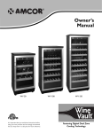
L−force Controls
Ä.NJgä
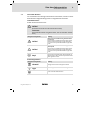
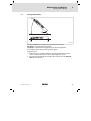
Betriebsanleitung
Operating Instructions
EXT. VIDEO
ADJ.
EXT. DATA
USB IN
U
DVI/USB TX4
Extender
0V
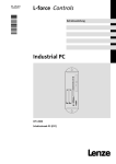
Industrial PC
DVI IN
BA_DVIUSB
.NJg
EPCZEBED
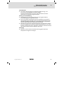
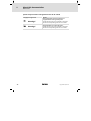
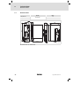
DVI/USB Extender V4
DVI/USB extender V4
l
,
,
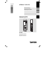
Lesen Sie zuerst diese Anleitung und die Dokumentation zum
Grundgerät, bevor Sie mit den Arbeiten beginnen!
Beachten Sie die enthaltenen Sicherheitshinweise.
Please read these instructions and the documentation of the standard
device before you start working!
Observe the safety instructions given therein!
Inhalt
1
2
3
4
5
6
i
Über diese Dokumentation . . . . . . . . . . . . . . . . . . . . . . . . . . . . . . . . . . . . . . . . .
5
1.1
1.2
1.3
1.4
2.5
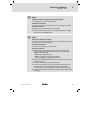
Informationen zur Gültigkeit . . . . . . . . . . . . . . . . . . . . . . . . . . . . . . . . .
Zielgruppe . . . . . . . . . . . . . . . . . . . . . . . . . . . . . . . . . . . . . . . . . . . . . . . .
Dokumenthistorie . . . . . . . . . . . . . . . . . . . . . . . . . . . . . . . . . . . . . . . . . .
Verwendete Konventionen . . . . . . . . . . . . . . . . . . . . . . . . . . . . . . . . . . .
Verwendete Hinweise . . . . . . . . . . . . . . . . . . . . . . . . . . . . . . . . . . . . . . .
5
5
6
6
7
Sicherheitshinweise . . . . . . . . . . . . . . . . . . . . . . . . . . . . . . . . . . . . . . . . . . . . . . .
9
2.1
Allgemeine Sicherheitshinweise . . . . . . . . . . . . . . . . . . . . . . . . . . . . . .
9
Produktbeschreibung . . . . . . . . . . . . . . . . . . . . . . . . . . . . . . . . . . . . . . . . . . . . .
12
3.1
3.2
3.3
3.4
3.5
Lieferumfang . . . . . . . . . . . . . . . . . . . . . . . . . . . . . . . . . . . . . . . . . . . . . .
Bedien− und Anzeigeelemente . . . . . . . . . . . . . . . . . . . . . . . . . . . . . . . .
Identifikation . . . . . . . . . . . . . . . . . . . . . . . . . . . . . . . . . . . . . . . . . . . . . .
Bestimmungsgemäße Verwendung . . . . . . . . . . . . . . . . . . . . . . . . . . . .
Gerätebeschreibung . . . . . . . . . . . . . . . . . . . . . . . . . . . . . . . . . . . . . . . .
12
13
14
14
15
Technische Daten . . . . . . . . . . . . . . . . . . . . . . . . . . . . . . . . . . . . . . . . . . . . . . . . .
16
4.1
4.2
4.3
Allgemeine Daten und Einsatzbedingungen . . . . . . . . . . . . . . . . . . . .
Elektrische Daten . . . . . . . . . . . . . . . . . . . . . . . . . . . . . . . . . . . . . . . . . . .
Mechanische Daten . . . . . . . . . . . . . . . . . . . . . . . . . . . . . . . . . . . . . . . .
16
17
18
Mechanische Installation . . . . . . . . . . . . . . . . . . . . . . . . . . . . . . . . . . . . . . . . . . .
19
5.1
5.2
5.3
Wichtige Hinweise . . . . . . . . . . . . . . . . . . . . . . . . . . . . . . . . . . . . . . . . . .
Montage DVI/USB TX4 . . . . . . . . . . . . . . . . . . . . . . . . . . . . . . . . . . . . . .
Montage DVI/USB RX4 . . . . . . . . . . . . . . . . . . . . . . . . . . . . . . . . . . . . . .
19
20
21
Elektrische Installation . . . . . . . . . . . . . . . . . . . . . . . . . . . . . . . . . . . . . . . . . . . . .
22
6.1
6.2
6.3
22
24
25
25
25
26
26
27
Wichtige Hinweise . . . . . . . . . . . . . . . . . . . . . . . . . . . . . . . . . . . . . . . . . .
Verdrahtung . . . . . . . . . . . . . . . . . . . . . . . . . . . . . . . . . . . . . . . . . . . . . . .
Anschlussbeschreibung . . . . . . . . . . . . . . . . . . . . . . . . . . . . . . . . . . . . . .
6.3.1
Netzanschluss . . . . . . . . . . . . . . . . . . . . . . . . . . . . . . . . . . . .
6.3.2
Ext. Video (Video−Übertragung) . . . . . . . . . . . . . . . . . . . . . .
6.3.3
Ext. Data (Daten−Übertragung) . . . . . . . . . . . . . . . . . . . . . .
6.3.4
DVI−Schnittstelle . . . . . . . . . . . . . . . . . . . . . . . . . . . . . . . . . .
6.3.5
USB−Schnittstelle . . . . . . . . . . . . . . . . . . . . . . . . . . . . . . . . . .
BA_DVIUSB DE/EN 5.0
l
3
i
7
Inhalt
Fehlersuche und Störungsbeseitigung . . . . . . . . . . . . . . . . . . . . . . . . . . . . . . . .
28
7.1
7.2
Statusanzeige . . . . . . . . . . . . . . . . . . . . . . . . . . . . . . . . . . . . . . . . . . . . . .
Übertragungsstrecke abgleichen . . . . . . . . . . . . . . . . . . . . . . . . . . . . . .
28
29
8
Wartung . . . . . . . . . . . . . . . . . . . . . . . . . . . . . . . . . . . . . . . . . . . . . . . . . . . . . . . .
30
9
Stichwortverzeichnis . . . . . . . . . . . . . . . . . . . . . . . . . . . . . . . . . . . . . . . . . . . . . .
31
4
l
BA_DVIUSB DE/EN 5.0
Über diese Dokumentation
1
Informationen zur Gültigkeit
0Abb. 0Tab. 0
1
Über diese Dokumentation
1.1
Informationen zur Gültigkeit
Diese Anleitung ist gültig für
ƒ DVI/USB TX4 (Sender)
ƒ DVI/USB RX4 (Empfänger)
1.2
Zielgruppe
Diese Dokumentation richtet sich an qualifiziertes Fachpersonal nach
IEC 60364.
Qualifiziertes Fachpersonal sind Personen, die für die auszuführenden Tätigkeiten bei der Aufstellung, Montage, Inbetriebsetzung und dem Betrieb des Produkts über entsprechende Qualifikationen verfügen.
I
Tipp!
Informationen und Hilfsmittel rund um die Lenze−Produkte finden
Sie im Download−Bereich unter
http://www.Lenze.com
BA_DVIUSB DE/EN 5.0
l
5
1
Über diese Dokumentation
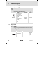
Dokumenthistorie
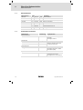
1.3
Dokumenthistorie
Materialnummer
1.4
Version
Beschreibung
.NJg
5.0
02/2014
TD06
Dokumentrevision
13385461
4.0
07/2011
TD29
Redaktionell überarbeitet
13288781
3.0
04/2009
TD29
Hardwareänderung (TX−V4, RX−V4)
13167768
2.0
11/2006
TD29
Firmierung angepasst
1.3
10/2006
Redaktionell überarbeitet
1.2
08/2005
Hardwareänderung (TX−V3, RX−V3)
1.1
03/2004
Hardwareänderung (TX−V2)
1.0
08/2004
Erstausgabe
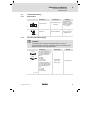
Verwendete Konventionen
Informationsart
Auszeichnung
Beispiele/Hinweise
Zahlenschreibweise
Dezimaltrennzeichen
Punkt
Es wird generell der Dezimalpunkt
verwendet.
Zum Beispiel: 1234.56
Warnhinweise
UL−Warnhinweise
UR−Warnhinweise
J
O
Werden in englischer und französischer Sprache verwendet.
Textauszeichnung
Programmname
»«
PC−Software
Zum Beispiel: »Engineer«, »Global
Drive Control« (GDC)
^
Verweis auf eine andere Seite mit
zusätzlichen Informationen
Zum Beispiel: ^ 16 = siehe Seite 16
Symbole
Seitenverweis
6
l
BA_DVIUSB DE/EN 5.0
Über diese Dokumentation
1
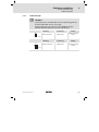
Verwendete Hinweise
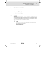
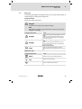
1.5
Verwendete Hinweise
Um auf Gefahren und wichtige Informationen hinzuweisen, werden in dieser
Dokumentation folgende Piktogramme und Signalwörter verwendet:
Sicherheitshinweise
Aufbau der Sicherheitshinweise:
}
Gefahr!
(kennzeichnet die Art und die Schwere der Gefahr)
Hinweistext
(beschreibt die Gefahr und gibt Hinweise, wie sie vermieden werden
kann)
Piktogramm und Signalwort
Bedeutung
{
Gefahr!
Gefahr von Personenschäden durch gefährliche elektrische Spannung
Hinweis auf eine unmittelbar drohende Gefahr, die den
Tod oder schwere Verletzungen zur Folge haben kann,
wenn nicht die entsprechenden Maßnahmen getroffen
werden.
Gefahr!
Gefahr von Personenschäden durch eine allgemeine
Gefahrenquelle
Hinweis auf eine unmittelbar drohende Gefahr, die den
Tod oder schwere Verletzungen zur Folge haben kann,
wenn nicht die entsprechenden Maßnahmen getroffen
werden.
Stop!
Gefahr von Sachschäden
Hinweis auf eine mögliche Gefahr, die Sachschäden zur
Folge haben kann, wenn nicht die entsprechenden Maßnahmen getroffen werden.
}
(
Anwendungshinweise
Piktogramm und Signalwort
)
I
,
BA_DVIUSB DE/EN 5.0
Bedeutung
Hinweis!
Wichtiger Hinweis für die störungsfreie Funktion
Tipp!
Nützlicher Tipp für die einfache Handhabung
Verweis auf andere Dokumentation
l
7
1
Über diese Dokumentation
Verwendete Hinweise
Spezielle Sicherheitshinweise und Anwendungshinweise für UL und UR
Piktogramm und Signalwort
Bedeutung
J
Warnings!
Sicherheitshinweis oder Anwendungshinweis für den
Betrieb eines UL−approbierten Geräts in UL−approbierten Anlagen.
Möglicherweise wird das Antriebssystem nicht UL−gerecht betrieben, wenn nicht die entsprechenden Maßnahmen getroffen werden.
Warnings!
Sicherheitshinweis oder Anwendungshinweis für den
Betrieb eines UR−approbierten Geräts in UL−approbierten Anlagen.
Möglicherweise wird das Antriebssystem nicht UL−gerecht betrieben, wenn nicht die entsprechenden Maßnahmen getroffen werden.
O
8
l
BA_DVIUSB DE/EN 5.0
Sicherheitshinweise
2
Allgemeine Sicherheitshinweise
2
Sicherheitshinweise
2.1
Allgemeine Sicherheitshinweise
Geltungsbereich
Die folgenden Sicherheitshinweise gelten allgemein für Lenze−Antriebs−und
Automatisierungskomponenten.
Beachten Sie unbedingt die produktspezifischen Sicherheits− und
Anwendungshinweise in dieser Dokumentation!
Auch zu Ihrer eigenen Sicherheit
}
Gefahr!
Wenn Sie die folgenden grundlegenden Sicherheitsmaßnahmen
missachten, kann dies zu schweren Personenschäden und
Sachschäden führen:
ƒ Lenze−Antriebs− und Automatisierungskomponenten ...
... ausschließlich bestimmungsgemäß verwenden.
... niemals trotz erkennbarer Schäden in Betrieb nehmen.
... niemals technisch verändern.
... niemals unvollständig montiert in Betrieb nehmen.
... niemals ohne erforderliche Abdeckungen betreiben.
... können während und nach dem Betrieb − ihrer Schutzart entsprechend −
spannungsführende, auch bewegliche oder rotierende Teile haben. Oberflächen können heiß sein.
ƒ Für Lenze−Antriebs− und Automatisierungskomponenten ...
... nur das zugelassene Zubehör verwenden.
... nur Original−Ersatzteile des Herstellers verwenden.
ƒ Alle Vorgaben der beiliegenden und zugehörigen Dokumentation
beachten.
Dies ist Voraussetzung für einen sicheren und störungsfreien Betrieb sowie
für das Erreichen der angegebenen Produkteigenschaften.
Die in diesem Dokument dargestellten verfahrenstechnischen Hinweise
und Schaltungsausschnitte sind Vorschläge, deren Übertragbarkeit auf die
jeweilige Anwendung überprüft werden muss. Für die Eignung der angegebenen Verfahren und Schaltungsvorschläge übernimmt der Hersteller keine
Gewähr.
BA_DVIUSB DE/EN 5.0
l
9
2
Sicherheitshinweise
Allgemeine Sicherheitshinweise
ƒ Alle Arbeiten mit und an Lenze−Antriebs− und
Automatisierungskomponenten darf nur qualifiziertes Fachpersonal
ausführen.
Nach IEC 60364 bzw. CENELEC HD 384 sind dies Personen, ...
... die mit Aufstellung, Montage, Inbetriebsetzung und Betrieb des Produkts
vertraut sind.
... die über die entsprechenden Qualifikationen für ihre Tätigkeit verfügen.
... die alle am Einsatzort geltenden Unfallverhütungsvorschriften, Richtlinien und Gesetze kennen und anwenden können.
Transport, Lagerung
ƒ Transport und Lagerung in trockener, schwingungsarmer Umgebung
ohne aggressiver Atmosphäre; möglichst in der Hersteller−Verpackung.
– Vor Staub und Stößen schützen.
– Klimatische Bedingungen gemäß den Technischen Daten einhalten.
Mechanische Installation
ƒ Das Produkt nach den Vorschriften der zugehörigen Dokumentation
aufstellen. Beachten Sie insbesondere den Abschnitt
"Einsatzbedingungen" im Kapitel "Technische Daten".
ƒ Sorgen Sie für sorgfältige Handhabung und vermeiden Sie mechanische
Überlastung. Verbiegen Sie bei der Handhabung weder Bauelemente
noch ändern Sie Isolationsabstände.
ƒ Das Produkt enthält elektrostatisch gefährdete Bauelemente, die durch
Kurzschluss oder statische Entladungen (ESD) leicht beschädigt werden
können. Berühren Sie deshalb elektronische Bauelemente und Kontakte
nur, wenn Sie zuvor ESD−Maßnahmen getroffen haben.
Elektrische Installation
ƒ Führen Sie die elektrische Installation nach den einschlägigen
Vorschriften durch (z. B. Leitungsquerschnitte, Absicherungen,
Schutzleiteranbindung). Zusätzliche Hinweise enthält die
Dokumentation.
ƒ Beachten Sie bei Arbeiten an unter Spannung stehenden Produkten die
geltenden nationalen Unfallverhütungsvorschriften (z. B. VBG 4).
ƒ Um die am Einbauort geltenden Grenzwerte für Funkstöraussendungen
einzuhalten, müssen Sie die Komponenten − falls in den Technischen
Daten vorgegeben − in Gehäuse (z. B. Schaltschränke) einbauen. Die
Gehäuse müssen einen EMV−gerechten Aufbau ermöglichen. Achten Sie
besonders darauf, dass z. B. Schaltschranktüren möglichst umlaufend
metallisch mit dem Gehäuse verbunden sind. Öffnungen oder
Durchbrüche durch das Gehäuse auf ein Minimum reduzieren.
ƒ Alle steckbaren Anschlussklemmen nur im spannungslosen Zustand
aufstecken oder abziehen!
10
l
BA_DVIUSB DE/EN 5.0
Sicherheitshinweise
2
Allgemeine Sicherheitshinweise
Inbetriebnahme
ƒ Sie müssen die Anlage ggf. mit zusätzlichen Überwachungs− und
Schutzeinrichtungen gemäß den jeweils gültigen
Sicherheitsbestimmungen ausrüsten (z. B. Gesetz über technische
Arbeitsmittel, Unfallverhütungsvorschriften).
Wartung und Instandhaltung
ƒ Die Komponenten sind wartungsfrei, wenn die vorgeschriebenen
Einsatzbedingungen eingehalten werden.
ƒ Bei verunreinigter Umgebungsluft können Kühlflächen verschmutzen
oder Kühlöffnungen verstopft werden. Bei diesen Betriebsbedingungen
deshalb regelmäßig die Kühlflächen und Kühlöffnungen reinigen. Dazu
niemals scharfe oder spitze Gegenstände verwenden!
ƒ Nachdem das System von der Versorgungsspannung getrennt ist, dürfen
Sie spannungsführende Geräteteile und Leistungsanschlüsse nicht sofort
berühren, weil Kondensatoren aufgeladen sein können. Beachten Sie dazu
die entsprechenden Hinweisschilder auf dem Gerät.
Entsorgung
ƒ Metalle und Kunststoffe zur Wiederverwertung geben. Bestückte
Leiterplatten fachgerecht entsorgen.
BA_DVIUSB DE/EN 5.0
l
11
3
Produktbeschreibung
Lieferumfang
3
Produktbeschreibung
3.1
Lieferumfang
Anzahl
Bezeichnung
1
DVI/USB Sender TX−V4
1
DVI/USB Empfänger RX−V4
1
USB−Kabel (Länge 2 m)
1
DVI−Kabel (Länge 2 m)
1
Spannungsversorgungskabel für Lenze−Monitor Panel
1
Phoenix Combicon−Stecker
1
DVD "PC based Automation"
)
Hinweis!
Überprüfen Sie nach Erhalt der Lieferung sofort, ob der
Lieferumfang mit den Warenbegleitpapieren übereinstimmt. Für
nachträglich reklamierte Mängel übernehmen wir keine
Gewährleistung.
Reklamieren Sie
ƒ erkennbare Transportschäden sofort beim Anlieferer.
ƒ erkennbare Mängel / Unvollständigkeit sofort bei der
zuständigen Lenze−Vertretung.
12
l
BA_DVIUSB DE/EN 5.0
Produktbeschreibung
3
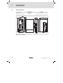
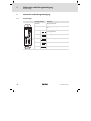
Bedien− und Anzeigeelemente
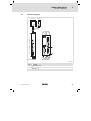
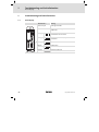
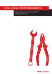
3.2
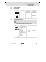
Bedien− und Anzeigeelemente
DVI OUT
USB OUT
0
DVI IN
ADJ.
U + 0V
EXT. DATA
EXT. DATA
USB IN
EXT. VIDEO
EXT. VIDEO
U + 0V
DVI/USB TX4
Extender
1
+
DVI/USB RX4
DVI/USB TX4
DVIUSB−001
Pos.
Beschreibung
0
Statusanzeige ^ 28
1
Abgleichschraube ^ 29
Anschlüsse ^ 25
BA_DVIUSB DE/EN 5.0
l
13
3
Produktbeschreibung
Identifikation
3.3
Identifikation
Lenze Automation GmbH
D-40667 Meerbusch
C
P/N
UL
R
US LISTED
File Exxxxxx
IND. CONT. EQ.
14ZZ
certified
107AT12345
107AT12345
DVIUSB−012
3.4
Typbezeichnung
Typschlüssel/Bestellnummer
Technische Daten
Hardware−/Firmware−Version
Materialnummer (kundenspezifisch)
Seriennummer als Barcode
Hersteller
Zertifizierung
Handzeichen Prüfer
Bestimmungsgemäße Verwendung
Der DVI/USB Sender TX−V4 und DVI/USB Empfänger RX−V4 werden bestimmungsgemäß verwendet, wenn sie ausschließlich gemeinsam zum Aufbau einer Visualisierungs− und Steuerungslösung zwischen einer Rechnereinheit (IPC)
und einem Lenze−Monitor Panel (MP 800 DVI ... MP 9000 DVI oder CS 5000 DVI
... CS 9000 DVI) eingesetzt werden und dabei die Vorgaben dieser Dokumentation befolgt werden. Eine andere oder darüber hinaus gehende Verwendung ist
nicht zulässig.
)
Hinweis!
Die Komponenten der V4−Serie sind inkompatibel mit denen der
V3−Serie (Vorgänger). Deshalb darf ein Sender/Empfänger der
V4−Serie nicht mit einem Empfänger/Sender der V3−Serie
verbunden werden.
Eine nichtbestimmungsgemäße Verwendung liegt auch bei einem Gebrauch
vor, der verhängnisvolle Risiken oder Gefahren birgt, die ohne Sicherstellung außergewöhnlich hoher Sicherheitsmaßnahmen zu Tod, Verletzung oder Sachschaden führen können.
14
l
BA_DVIUSB DE/EN 5.0
Produktbeschreibung
3
Gerätebeschreibung
3.5
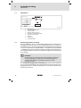
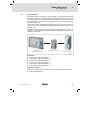
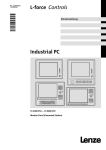
Gerätebeschreibung
Die DVI/USB−Extender−Technologie wird für den dezentralen Aufbau zwischen
einer Rechnereinheit (IPC/Controller) und einer Anzeigeeinheit (Monitor Panel)
im industriellen Umfeld verwendet. Damit lassen sich PC−basierte Visualisierungs− und Steuerungslösungen unter verschiedenen Umgebungsbedingungen realisieren, die eine Trennung von Bedien− und Rechnereinheit erfordern.
Das System besteht aus einem DVI/USB−Sender (TX4), welcher in der Nähe der
Rechnereinheit montiert wird und einem DVI/USB−Empfänger (RX4), welcher in
oder an einer Anzeigeeinheit befestigt werden kann.
Sämtliche Signale − digitale Echtzeit Bildinformationen, USB−Peripherie, Maus
und Tastatur − werden über ein TwinLAN−Kabel übertragen. Auch die Spannungsversorgung für die Anzeigeeinheit läuft über dieses Kabel.
Monitor Panel
mit DVI/USB-Empfänger
DVI/USB-Sender
IPC/Controller
(hier: CPC 2800)
DVIUSB−002
Zubehör
ƒ Übertragungskabel TwinLAN 10 m
ƒ Übertragungskabel TwinLAN 15 m
ƒ Übertragungskabel TwinLAN 20 m
ƒ Übertragungskabel TwinLAN 25 m
ƒ Übertragungskabel TwinLAN 30 m
ƒ Übertragungskabel TwinLAN 35 m
Optionales Zubehör
(Im Lieferumfang ist ein DVI− und ein USB−Kabel enthalten; Länge jeweils 2 m)
ƒ Kabelsatz DVI/USB 5 m
BA_DVIUSB DE/EN 5.0
l
15
4
Technische Daten
Allgemeine Daten und Einsatzbedingungen
4
Technische Daten
4.1
Allgemeine Daten und Einsatzbedingungen
Allgemeine Daten
Konformität und Approbation
Konformität
CE
EN 61000−6−4
EN 61000−6−2
EMV−Richtlinie, Klasse A, Industriebereich
UL 508
CSA C22.2
Programmable Controllers (File−No. E236341)
Approbation
UL
UL−Listed: Monitor Panel
MP 800 DVI − MP9000 DVI
UL−Recognized: Command Station
CS 5000 DVI − CS 9000 DVI
Sonstiges
RoHS
−
Produkte bleifrei gemäß CE−Richtlinie 2011/65/EU
Personenschutz und Geräteschutz
Schutzart
16
DVI/USB TX4
IP30
DVI/USB RX4
IP20
Schutzklasse
1
Überspannungskategorie
II
Isolationsfestigkeit
500 V
l
BA_DVIUSB DE/EN 5.0
Technische Daten
4
Elektrische Daten
Einsatzbedingungen
Montagebedingungen
Einbauort
DVI/USB TX4
Im Schaltschrank, in der Nähe des IPCs
Leitungslänge IPC <−> DVI/USB TX4:
l Standard−Kabel (Lieferumfang): max. 2 m
l Lenze−Kabelsatz DVI/USB: 5 m
DVI/USB RX4
Beim MP−System: an der Rückseite des Gerätes
Beim CS−System: in der Montagewanne des Gerätes
Leitungslänge DVI/USB TX4 <−> RX4: 10 ... 35 m
Umgebungsbedingungen
Klimatisch
Lagerung
−25 ... +70 °C
Transport
−25 ... +70 °C
Betrieb
0 ... +50 °C
Relative Luftfeuchte
10 ... 95 %, nicht kondensierend
Aufstellhöhe
4.2
< 3000 m üNN
Elektrische Daten
Bemessungsdaten
Betriebsspannung
+24 V DC (18 ... 30 V)
Bei MP 9000 DVI/CS 9000 DVI und einer Übertragungsstrecke > 20 m:
+24 V DC (20 ... 30 V)
Eingangsstrom DVI/USB TX
ohne opt. Versorgung der Anzeigeeinheit
max. 0.2 A (Standby < 50 mA)
mit opt. Versorgung der Anzeigeeinheit
max. 2 A
Ausgangsstrom DVI/USB RX
(opt. 24−V−Versorgung der Anzeigeeinheit)
max. 1.8 A
Übertragbare Grafik−Auflösung
VGA (640 x 480 Pixel) bis SXGA (1280 x 1024 Pixel)
USB−Anschluss
USB 1.1 und 2.0, max. 12 MBit/s (Full Speed)
BA_DVIUSB DE/EN 5.0
l
17
4
Technische Daten
Mechanische Daten
4.3
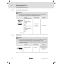
Mechanische Daten
Ausführung
DVI/USB TX4
Masse
1.0
Stahlblech
DVI/USB RX4
0.6
Æ5.5
27.5
0V
DVI/USB RX4
Extender
U
DVI/USB TX4
Extender
100
172.5
EXT. VIDEO
190
140
DVI IN
ADJ.
17.5
EXT. DATA
USB IN
183
4
M4
+
52
101.5
DVI/USB−003
Alle Maße in Millimeter.
18
l
BA_DVIUSB DE/EN 5.0
Mechanische Installation
5
Wichtige Hinweise
5
Mechanische Installation
5.1
Wichtige Hinweise
ƒ Die Installation darf nur von qualifiziertem Fachpersonal durchgeführt
werden, das mit den geltenden nationalen Normen vertraut ist.
ƒ Kontrollieren Sie vor der Installation,
– ob die "bestimmungsgemäße Verwendung" eingehalten wird (¶ 14).
– ob die in den Technischen Daten genannten Einsatzbedingungen
eingehalten werden (¶ 16); ggf. zusätzliche Maßnahmen ergreifen.
– ob der Montageort und das Montagematerial die mechanische
Verbindung dauerhaft gewährleistet.
(
Stop!
Kurzschluss und statische Entladungen
Das Gerät enthält Bauelemente, die bei Kurzschluss oder statischer
Entladung gefährdet sind.
Mögliche Folgen:
ƒ Das Gerät oder Teile davon werden zerstört.
Schutzmaßnahmen:
ƒ Bei allen Arbeiten am Gerät, immer Spannungsversorgung
abschalten (Netz und eine evtl. montierte USV). Dies gilt
insbesondere:
– vor dem Öffnen des Gehäuses.
– vor dem Anschließen / Abziehen von Steckverbindern.
– vor dem Stecken / Ziehen von Modulen.
ƒ Alle Personen, die Flachbaugruppen handhaben, müssen
ESD−Maßnahmen berücksichtigen.
ƒ Kontakte von Steckverbindern dürfen nicht berührt werden.
ƒ Flachbaugruppen dürfen nur an kontaktfreien Stellen angefasst
werden und nur auf geeigneten Unterlagen abgelegt werden
(z. B. auf ESD−Verpackung oder leitfähigem Schaumstoff).
ƒ Flachbaugruppen dürfen nur in ESD−Verpackungen transportiert
und gelagert werden.
BA_DVIUSB DE/EN 5.0
l
19
5
Mechanische Installation
Montage DVI/USB TX4
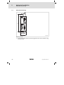
5.2
Montage DVI/USB TX4
EXT. VIDEO
ADJ.
DVI IN
USB IN
EXT. DATA
183
U
DVI/USB TX4
Extender
0V
Æ5.5
52
DVIUSB−004
So gehen Sie vor:
1. Schrauben Sie den DVI/USB TX4 mit zwei Schrauben M5 an die
Schaltschrank−Montageplatte.
20
l
BA_DVIUSB DE/EN 5.0
Mechanische Installation
5
Montage DVI/USB RX4
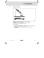
5.3
Montage DVI/USB RX4
1
0
1
0
DVIUSB−005
Der DVI/USB RX4 kann an folgende Systeme montiert werden:
MP−System: an der Rückseite des Gerätes
CS−System: innerhalb der Montagewanne auf dem Montageblech
Die Vorgehensweise ist bei beiden Systemen gleich.
So gehen Sie vor:
1. Positionieren Sie den DVI/USB RX4 so, dass die beiden Nasen 0 in die
Löcher im MP−Gehäuse bzw. in der CS−Montagewanne fassen.
2. Schrauben Sie die Rändelschraube 1 an der anderen Seite des DVI/USB
RX4 mit der Hand fest.
BA_DVIUSB DE/EN 5.0
l
21
6
Elektrische Installation
Wichtige Hinweise
6
Elektrische Installation
6.1
Wichtige Hinweise
ƒ Die Installation darf nur von qualifiziertem Fachpersonal durchgeführt
werden, das mit den geltenden nationalen Normen vertraut ist.
ƒ Das Gerät darf nur vollständig montiert in Betrieb genommen werden.
22
l
BA_DVIUSB DE/EN 5.0
Elektrische Installation
6
Wichtige Hinweise
(
Stop!
Kein Geräteschutz für zu hohe Eingangsspannung
Der Spannungseingang ist intern nicht abgesichert.
Mögliche Folgen:
ƒ Zerstörung des Gerätes bei zu hoher Eingangsspannung.
Schutzmaßnahmen:
ƒ Beachten Sie die maximal zulässige Eingangsspannung.
ƒ Sichern Sie das Gerät eingangsseitig fachgerecht gegen
Spannungsschwankungen und −spitzen ab.
(
Stop!
Kurzschluss und statische Entladungen
Das Gerät enthält Bauelemente, die bei Kurzschluss oder statischer
Entladung gefährdet sind.
Mögliche Folgen:
ƒ Das Gerät oder Teile davon werden zerstört.
Schutzmaßnahmen:
ƒ Bei allen Arbeiten am Gerät, immer Spannungsversorgung
abschalten (Netz und eine evtl. montierte USV). Dies gilt
insbesondere:
– vor dem Öffnen des Gehäuses.
– vor dem Anschließen / Abziehen von Steckverbindern.
– vor dem Stecken / Ziehen von Modulen.
ƒ Alle Personen, die Flachbaugruppen handhaben, müssen
ESD−Maßnahmen berücksichtigen.
ƒ Kontakte von Steckverbindern dürfen nicht berührt werden.
ƒ Flachbaugruppen dürfen nur an kontaktfreien Stellen angefasst
werden und nur auf geeigneten Unterlagen abgelegt werden
(z. B. auf ESD−Verpackung oder leitfähigem Schaumstoff).
ƒ Flachbaugruppen dürfen nur in ESD−Verpackungen transportiert
und gelagert werden.
BA_DVIUSB DE/EN 5.0
l
23
6
Elektrische Installation
Verdrahtung
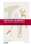
6.2
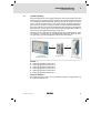
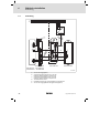
Verdrahtung
L1
N
PE
F
L1 N
+
~
=
0V
0
0.4 m
4
2
ADJ.
10 ... 35 m
DVI OUT USB OUT
U 0V
USB IN
EXT. DATA
0V U
EXT. DATA
EXT. VIDEO
USB IN
3
1
DVI IN
DVI IN
0.5 m
DVI/USB TX4
Extender
5
+ +24
2m/5m
+
DVI/USB-RX4
MP 800 DVI ... MP 9000 DVI
CS 5000 DVI ... CS 9000 DVI
DVI/USB-TX4
IPC/Controller
DVIUSB−006
0
1
2
3
4
5
24
24−V−DC−Versorgungskabel
Standard USB−Kabel (Lieferumfang, 2 m) oder
Kabelsatz USB/DVI (Zubehör, 5 m) von Lenze
Standard DVI−Kabel (Lieferumfang, 2 m) oder
Kabelsatz USB/DVI (Zubehör, 5 m) von Lenze
TwinLAN−Kabel von Lenze
Konfektionierte Leitungen mit USB−B−Stecker und DVI−Buchse
24−V−DC−Versorgungskabel für Anzeigeeinheit (optional)
l
BA_DVIUSB DE/EN 5.0
Elektrische Installation
6
Anschlussbeschreibung
Netzanschluss
6.3
Anschlussbeschreibung
6.3.1
Netzanschluss
Beschreibung
0V
U
Anschluss DC 24 V
Anschlusstyp
Kabeltyp
3−pol. Phoenix CombiconBuchse
Kabel (Leiterquerschnitt max. 2.5 mm2)
mit Phoenix Combicon−
Stecker, MSTB 2.5 /
3−STF−5.08
M4−Gewindebolzen
Separater Erdungsleiter
(min. 2,5 mm2) mit
Ringkabelschuh
IPC001
Anschluss PE
IPC001
6.3.2
Ext. Video (Video−Übertragung)
)
Hinweis!
Verwenden Sie nur Original−TwinLAN−Kabel von Lenze, da
andernfalls die Funktion der Übertragung und die Einhaltung der
EMV−Grenzwerte nicht gewährleistet ist.
TX4 1
9
1 RX4
9
Beschreibung
Anschlusstyp
Kabeltyp
Pin 1: RX2+ (Panel Data 2+)
Pin 2: RX1+ (Panel Data 1+)
Pin 3: RX0+ (Panel Data 0+)
Pin 4: RXC+ (Panel Data
Clock+)
Pin 5: GND
Pin 6: GND
Pin 7: reserviert
Pin 8: reserviert
Pin 9: RX2− (Panel Data 2−)
Pin 10: RX1− (Panel Data 1−)
Pin 11: RX0− (Panel Data 0−)
Pin 12: RXC− (Panel Data
Clock−)
Pin 13: GND
Pin 14: GND
Pin 15: reserviert
15−pol. SUB−D
TX4: Buchse
RX4: Stecker
TwinLAN (CAT7)
DVIUSB−007
BA_DVIUSB DE/EN 5.0
l
25
6
Elektrische Installation
Anschlussbeschreibung
Ext. Data (Daten−Übertragung)
6.3.3
Ext. Data (Daten−Übertragung)
)
Hinweis!
Verwenden Sie nur Original−TwinLAN−Kabel von Lenze, da
andernfalls die Funktion der Übertragung und die Einhaltung der
EMV−Grenzwerte nicht gewährleistet ist.
1 TX4
9
RX4 1
9
Beschreibung
Anschlusstyp
Kabeltyp
Pin 1: USB+ (USB−Kanal +)
Pin 2: −
Pin 3: +24 V optional
Pin 4: DDC D (DDC Daten)
Pin 5: GND
Pin 6: GND
Pin 7: −
Pin 8: −
Pin 9: USB− (USB−Kanal −)
Pin 10: −
Pin 11: +24 V
Pin 12: DDC C (DDC Takt)
Pin 13: GND
Pin 14: −
Pin 15: −
15−pol. SUB−D
TX4: Stecker
RX4: Buchse
TwinLAN (CAT7)
DVIUSB−007
6.3.4
DVI−Schnittstelle
)
Hinweis!
Verwenden Sie nur das DVI−Kabel aus dem Lieferumfang oder ein
nachfolgend angegebenes DVI−Kabel mit max. 2 m Länge.
Entfernungen bis zu 5 m können Sie ausschließlich mit dem
Zubehör "Kabelsatz DVI/USB" von Lenze überbrücken.
Beschreibung
Standard DVI−Schnittstelle
Anschlusstyp
Kabeltyp
DVI−I−Buchse
DVI−I Single−Link (18+5)
DVI−I Double−Link
(24+5)
DVI−D Single−Link
(18+1)
DVI−D Double−Link
(24+1)
IPC001
26
l
BA_DVIUSB DE/EN 5.0
Elektrische Installation
6
Anschlussbeschreibung
USB−Schnittstelle
6.3.5
USB−Schnittstelle
)
Hinweis!
Verwenden Sie nur das USB−Kabel aus dem Lieferumfang oder ein
Standard−USB−Kabel mit max. 2 m Länge.
Entfernungen bis zu 5 m können Sie ausschließlich mit dem
Zubehör "Kabelsatz DVI/USB" von Lenze überbrücken.
Beschreibung
Anschlusstyp
Kabeltyp
USB−Host−Anschluss
USB−A−Buchse
USB−Kabel mit USB−A−
Stecker
Beschreibung
Anschlusstyp
Kabeltyp
USB−Device−Anschluss
USB−B−Buchse
USB−Kabel mit USB−B−
Stecker
IPC001
USB
DVIUSB−010
BA_DVIUSB DE/EN 5.0
l
27
7
Fehlersuche und Störungsbeseitigung
Statusanzeige
7
Fehlersuche und Störungsbeseitigung
7.1
Statusanzeige
Bedeutung
Dauerlicht
Bildsignal vorhanden
Aus
Versorgungsspannung fehlt oder Hardwaredefekt
Blinkt
Kein Bildsignal vorhanden, Rechner aus oder
nicht angeschlossen
Blinkt
Kein Bildsignal vorhanden, Rechner an
0V
EXT. VIDEO
USB IN
U
DVI/USB TX4
Extender
Verhalten der LED 0
DVI IN
Keinen Monitor gefunden
Blinkt
Kabeldefekt
Flimmert
Hardwaredefekt
ADJ.
EXT. DATA
0 Blinkt
28
l
BA_DVIUSB DE/EN 5.0
Fehlersuche und Störungsbeseitigung
7
Übertragungsstrecke abgleichen
ADJ.
DVI IN
Übertragungsstrecke abgleichen
EXT. DATA
7.2
1
DVIUSB−009
Wenn Störungen in der Bilddarstellung (Streifen oder Pixel−Flimmern) auftreten, kann ein senderseitiger Abgleich der Video−Übertragungsstrecke erforderlich sein.
So gehen Sie dabei vor:
1. Kontrollieren Sie vor dem Abgleich die Verkabelung und die Anschlüsse
auf festen Sitz, da eine fehlerhafte Verkabelung ebenfalls Bildstörungen
verursachen kann.
2. Schalten Sie alle Geräte ein und warten Sie ca. 5 Minuten, damit sie ihre
Betriebstemperatur erreicht haben.
3. Drehen Sie die Abgleichschraube 1 mindestens 20 Umdrehungen gegen
den Uhrzeigersinn, damit sichergestellt ist, dass sich das Poti an seinem
linken Anschlag befindet.
Eventuell wird jetzt gar kein Bild mehr angezeigt (Verbindungsabbruch).
4. Drehen Sie die Abgleichschraube 1 im Uhrzeigersinn, bis keine
Bildstörungen mehr auftreten.
Wenn nach mehreren Umdrehungen immer noch kein Bild angezeigt wird,
schalten Sie die angeschlossene Anzeigeeinheit aus und wieder ein.
5. Drehen Sie die Abgleichschraube weiter im Uhrzeigersinn, bis wieder
Bildstörungen auftreten. Zählen Sie dabei die Anzahl Umdrehungen.
6. Drehen Sie die Abgleichschraube jetzt die Hälfte der gezählten
Umdrehungen zurück.
BA_DVIUSB DE/EN 5.0
l
29
8
Wartung
8
Wartung
Das Gerät ist wartungsfrei. Trotzdem müssen Sie in regelmäßigen und unter Berücksichtigung der Umgebungsbedingungen ausreichend kurzen Intervallen
eine Sichtprüfung durchführen.
Kontrollieren Sie:
ƒ Entspricht die Umgebung des Gerätes noch den in den Technischen Daten
genannten Einsatzbedingungen?
ƒ Behindert kein Staub oder Schmutz die Wärmeabfuhr des Gerätes?
ƒ Sind die mechanischen und elektrischen Verbindungen in Ordnung?
30
l
BA_DVIUSB DE/EN 5.0
Stichwortverzeichnis
9
9
Stichwortverzeichnis
A
G
Abgleich der Übertragungsstrecke, 29
Gefahr
Allgemeine Daten, 16
− Kurzschluss, 19, 23
− Statische Entladung, 19, 23
Anschlüsse, 25
Gerät, Übersicht, 13
Anzeigeelemente, 13
Gerätebeschreibung, 15
Approbation, 16
Aufstellhöhe, 17
H
Ausführung, 18
Hinweise, Definiton, 7
B
I
Bedienelemente, 13
Identfikation, 14
Bestimmungsgemäße Verwendung, 14
Installation, elektrische, 22
− Verdrahtungsplan, 24
D
Installation, mechanische, 19
Daten−Übertragung, 26
Isolationsfestigkeit, 16
Definition der verwendeten Hinweise, 7
K
DVI−Anschluss, 26
Konformität, 16
E
Kurzschluss, 19, 23
Einbauort, 17
Einsatzbedingungen, 17
L
Elektrische Daten, 17
Lieferumfang, 12
Elektrische Installation, 22
M
−
−
−
−
−
−
Daten−Übertragung, 26
Monitor, 26
Netz, 25
USB, intern, 27
USB−Anschluss, 27
Video−Übertragung, 25
Masse, 18
Mechanische Daten, 18
Mechanische Installation, 19
Monitor−Anschluss, 26, 27
Montage
Entsorgung, 11
− DVI/USB RX4, 21
− DVI/USB TX4, 20
F
Montagebedingungen, Einbauort, 17
Fehlersuche, 28
BA_DVIUSB DE/EN 5.0
l
31
9
Stichwortverzeichnis
N
Temperaturen, 17
Netzanschluss, 25
Typenschild, 14
P
Typenschlüssel, finden, 14
Produktbeschreibung, 12
U
− Bestimmungsgemäße Verwendung, 14
Übersicht, 13
− Anschlüsse, 25
S
Überspannungskategorie, 16
Schutzart, 16
Schutzklasse, 16
Sicherheitshinweise, 9
− Bestimmungsgemäße Verwendung, 14
− Definition, 7
− Gestaltung, 7
Übertragungsstreche abgleichen, 29
Umgebungsbedingungen
− Aufstellhöhe, 17
− klimatisch, 17
USB−Anschluss, 27
− intern, 27
Statische Entladung, 19, 23
Statusmeldungen, 28
V
Störungsbeseitigung, 28
Video−Übertragung, 25
T
W
Technische Daten, 16
Wartung, 30
−
−
−
−
Allgemeine Daten, 16
Einsatzbedingungen, 17
Elektrische Daten, 17
Mechanische Daten, 18
32
Z
Zubehör, 15
l
BA_DVIUSB DE/EN 5.0
Contents
1
2
3
4
5
6
i
About this documentation . . . . . . . . . . . . . . . . . . . . . . . . . . . . . . . . . . . . . . . . . .
35
1.1
1.2
1.3
1.4
2.5
Validity information . . . . . . . . . . . . . . . . . . . . . . . . . . . . . . . . . . . . . . . .
Target group . . . . . . . . . . . . . . . . . . . . . . . . . . . . . . . . . . . . . . . . . . . . . .
Document history . . . . . . . . . . . . . . . . . . . . . . . . . . . . . . . . . . . . . . . . . .
Conventions used . . . . . . . . . . . . . . . . . . . . . . . . . . . . . . . . . . . . . . . . . . .
Notes used . . . . . . . . . . . . . . . . . . . . . . . . . . . . . . . . . . . . . . . . . . . . . . . .
35
35
35
36
37
Safety instructions . . . . . . . . . . . . . . . . . . . . . . . . . . . . . . . . . . . . . . . . . . . . . . . .
39
2.1
General safety information . . . . . . . . . . . . . . . . . . . . . . . . . . . . . . . . . . .
39
Product description . . . . . . . . . . . . . . . . . . . . . . . . . . . . . . . . . . . . . . . . . . . . . . .
42
3.1
3.2
3.3
3.4
3.5
Scope of supply . . . . . . . . . . . . . . . . . . . . . . . . . . . . . . . . . . . . . . . . . . . .
Controls and displays . . . . . . . . . . . . . . . . . . . . . . . . . . . . . . . . . . . . . . . .
Identification . . . . . . . . . . . . . . . . . . . . . . . . . . . . . . . . . . . . . . . . . . . . . .
Application as directed . . . . . . . . . . . . . . . . . . . . . . . . . . . . . . . . . . . . . .
Device description . . . . . . . . . . . . . . . . . . . . . . . . . . . . . . . . . . . . . . . . . .
42
43
44
44
45
Technical data . . . . . . . . . . . . . . . . . . . . . . . . . . . . . . . . . . . . . . . . . . . . . . . . . . . .
46
4.1
4.2
4.3
General data and operating conditions . . . . . . . . . . . . . . . . . . . . . . . .
Electrical data . . . . . . . . . . . . . . . . . . . . . . . . . . . . . . . . . . . . . . . . . . . . . .
Mechanical data . . . . . . . . . . . . . . . . . . . . . . . . . . . . . . . . . . . . . . . . . .
46
47
48
Mechanical installation . . . . . . . . . . . . . . . . . . . . . . . . . . . . . . . . . . . . . . . . . . . .
49
5.1
5.2
5.3
Important notes . . . . . . . . . . . . . . . . . . . . . . . . . . . . . . . . . . . . . . . . . . . .
DVI/USB TX4 mounting . . . . . . . . . . . . . . . . . . . . . . . . . . . . . . . . . . . . . .
DVI/USB RX4 mounting . . . . . . . . . . . . . . . . . . . . . . . . . . . . . . . . . . . . . .
49
50
51
Electrical installation . . . . . . . . . . . . . . . . . . . . . . . . . . . . . . . . . . . . . . . . . . . . . .
52
6.1
6.2
6.3
52
54
55
55
55
56
56
57
Important notes . . . . . . . . . . . . . . . . . . . . . . . . . . . . . . . . . . . . . . . . . . . .
Wiring . . . . . . . . . . . . . . . . . . . . . . . . . . . . . . . . . . . . . . . . . . . . . . . . . . . .
Terminal description . . . . . . . . . . . . . . . . . . . . . . . . . . . . . . . . . . . . . . . .
6.3.1
Mains connection . . . . . . . . . . . . . . . . . . . . . . . . . . . . . . . . .
6.3.2
Ext. video (video transmission) . . . . . . . . . . . . . . . . . . . . . .
6.3.3
Ext. data (data transmission) . . . . . . . . . . . . . . . . . . . . . . . .
6.3.4
DVI interface . . . . . . . . . . . . . . . . . . . . . . . . . . . . . . . . . . . . .
6.3.5
USB interface . . . . . . . . . . . . . . . . . . . . . . . . . . . . . . . . . . . . .
BA_DVIUSB DE/EN 5.0
l
33
i
7
Contents
Troubleshooting and fault elimination . . . . . . . . . . . . . . . . . . . . . . . . . . . . . . .
58
7.1
7.2
Status display . . . . . . . . . . . . . . . . . . . . . . . . . . . . . . . . . . . . . . . . . . . . . .
Adjusting the transmission path . . . . . . . . . . . . . . . . . . . . . . . . . . . . . .
58
59
8
Maintenance . . . . . . . . . . . . . . . . . . . . . . . . . . . . . . . . . . . . . . . . . . . . . . . . . . . . .
60
9
Index . . . . . . . . . . . . . . . . . . . . . . . . . . . . . . . . . . . . . . . . . . . . . . . . . . . . . . . . . . .
61
34
l
BA_DVIUSB DE/EN 5.0
About this documentation
1
Validity information
0Fig. 0Tab. 0
1
About this documentation
1.1
Validity information
These instructions are valid for
ƒ DVI/USB TX4 (transmitter)
ƒ DVI/USB RX4 (receiver)
1.2
Target group
This documentation is directed at qualified skilled personnel according to
IEC 60364.
Qualified skilled personnel are persons who have the required qualifications to
carry out all activities involved in installing, mounting, commissioning, and
operating the product.
I
Tip!
Information and auxiliary devices related to the Lenze products can
be found in the download area at
http://www.Lenze.com
1.3
Document history
Material number
Vresion
Description
.NJg
5.0
02/2014
TD06
Document revision
13385461
4.0
07/2011
TD29
Editorial revision
13288781
3.0
04/2009
TD29
Hardware revision (TX−V4, RX−V4)
13167768
2.0
11/2006
TD29
Changed legal company address
1.3
10/2006
Editorial revision
1.2
08/2005
Hardware revision (TX−V3, RX−V3)
1.1
03/2004
Hardware revision (TX−V2)
1.0
08/2004
First edition
BA_DVIUSB DE/EN 5.0
l
35
1
About this documentation
Conventions used
1.4
Conventions used
Type of information
Identification
Examples/notes
Spelling of numbers
Decimal separator
Point
In general, the decimal point is used.
For instance: 1234.56
Warnings
UL warnings
UR warnings
J
O
Given in English and French
Text
Program name
»«
PC software
For example: »Engineer«, »Global
Drive Control« (GDC)
^
Reference to another page with
additional information
For instance: ^ 16 = see page 16
Icons
Page reference
36
l
BA_DVIUSB DE/EN 5.0
About this documentation
1
Notes used
1.5
Notes used
The following pictographs and signal words are used in this documentation to
indicate dangers and important information:
Safety instructions
Structure of safety instructions:
}
Danger!
(characterises the type and severity of danger)
Note
(describes the danger and gives information about how to prevent
dangerous situations)
Pictograph and signal word
Meaning
{
Danger!
Danger of personal injury through dangerous electrical
voltage.
Reference to an imminent danger that may result in
death or serious personal injury if the corresponding
measures are not taken.
Danger!
Danger of personal injury through a general source of
danger.
Reference to an imminent danger that may result in
death or serious personal injury if the corresponding
measures are not taken.
Stop!
Danger of property damage.
Reference to a possible danger that may result in
property damage if the corresponding measures are not
taken.
}
(
Application notes
Pictograph and signal word
)
I
,
BA_DVIUSB DE/EN 5.0
Meaning
Note!
Important note to ensure troublefree operation
Tip!
Useful tip for simple handling
Reference to another documentation
l
37
1
About this documentation
Notes used
Special safety instructions and application notes for UL and UR
Pictograph and signal word
Meaning
J
Warnings!
Safety or application note for the operation of a
UL−approved device in UL−approved systems.
Possibly the drive system is not operated in compliance
with UL if the corresponding measures are not taken.
Warnings!
Safety or application note for the operation of a
UR−approved device in UL−approved systems.
Possibly the drive system is not operated in compliance
with UL if the corresponding measures are not taken.
O
38
l
BA_DVIUSB DE/EN 5.0
Safety instructions
2
General safety information
2
Safety instructions
2.1
General safety information
Scope
The following general safety instructions apply to all Lenze drive and
automation components.
The product−specific safety and application notes given in this documentation
must be observed!
For your own safety
}
Danger!
Disregarding the following basic safety measures may lead to
severe personal injury and damage to material assets!
ƒ Lenze drive and automation components ...
... must only be used for the intended purpose.
... must never be operated if damaged.
... must never be subjected to technical modifications.
... must never be operated unless completely assembled.
... must never be operated without the covers/guards.
... can − depending on their degree of protection − have live, movable or
rotating parts during or after operation. Surfaces can be hot.
ƒ For Lenze drive and automation components ...
... only use approved accessories.
... only use original manufacturer spare parts.
ƒ All specifications of the corresponding enclosed documentation must be
observed.
This is vital for a safe and trouble−free operation and for achieving the
specified product features.
The procedural notes and circuit details provided in this document are
proposals which the user must check for suitability for his application. The
manufacturer does not accept any liability for the suitability of the specified
procedures and circuit proposals.
BA_DVIUSB DE/EN 5.0
l
39
2
Safety instructions
General safety information
ƒ Only qualified skilled personnel are permitted to work with or on Lenze
drive and automation components.
According to IEC 60364 or CENELEC HD 384, these are persons ...
... who are familiar with the installation, assembly, commissioning and
operation of the product,
... possess the appropriate qualifications for their work,
... and are acquainted with and can apply all the accident prevent
regulations, directives and laws applicable at the place of use.
Transport, storage
ƒ Transport and storage in a dry, low−vibration environment without
aggressive atmosphere; preferably in the packaging provided by the
manufacturer.
– Protect against dust and shocks.
– Comply with climatic conditions according to the technical data.
Mechanical installation
ƒ Install the product according to the regulations of the corresponding
documentation. In particular observe the section "Operating conditions"
in the chapter "Technical data".
ƒ Provide for a careful handling and avoid mechanical overload. During
handling neither bend components, nor change the insulation distances.
ƒ The product contains electrostatic sensitive devices which can easily be
damaged by short circuit or static discharge (ESD). Thus, electronic
components and contacts must not be touched unless ESD measures are
taken beforehand.
Electrical installation
ƒ Carry out the electrical installation according to the relevant regulations
(e. g. cable cross−sections, fusing, connection to the PE conductor).
Additional notes are included in the documentation.
ƒ Applicable national regulations for the prevention of accidents (e.g. VBG
4) must be observed when working on live products.
ƒ For compliance with the limit values for radio interference emission at the
site of installation, the components − if specified in the technical data −
have to be mounted in housings (e. g. control cabinets). The housings
have to enable an EMC−compliant installation. In particular observe that
for example control cabinet doors preferably have a circumferential
metallic connection to the housing. Reduce openings or cutouts through
the housing to a minimum.
ƒ Only plug in or remove pluggable terminals in the deenergised state!
40
l
BA_DVIUSB DE/EN 5.0
Safety instructions
2
General safety information
Commissioning
ƒ If required, you have to equip the system with additional monitoring and
protective devices in accordance with the respective valid safety
regulations (e. g. law on technical equipment, regulations for the
prevention of accidents).
Maintenance and servicing
ƒ The components are maintenance−free if the required operating
conditions are observed.
ƒ If the cooling air is polluted, the cooling surfaces may be contaminated or
the air vents may be blocked. Under these operating conditions, the
cooling surfaces and air vents must be cleaned at regular intervals. Never
use sharp objects for this purpose!
ƒ After the system has been disconnected from the supply voltage, live
components and power connections must not be touched immediately
because capacitors may be charged. Please observe the corresponding
notes on the device.
Disposal
ƒ Recycle metals and plastic materials. Ensure professional disposal of
assembled PCBs.
BA_DVIUSB DE/EN 5.0
l
41
3
Product description
Scope of supply
3
Product description
3.1
Scope of supply
Quantity Name
1
TX−V4 DVI/USB transmitter
1
RX−V4DVI/USB receiver
1
USB cable (length 2 m)
1
DVI cable (length 2 m)
1
Voltage supply cable for Lenze monitor panel
1
Phoenix Combicon plug
1
DVD "PC based Automation"
1
Test report
1
Device pass card
)
Note!
After receipt of the delivery, check immediately whether the items
match the accompanying papers. We do not accept any liability for
deficiencies claimed subsequently.
Claim
ƒ visible transport damage immediately to the forwarder
ƒ visible deficiencies/incompleteness immediately to your Lenze
representative.
42
l
BA_DVIUSB DE/EN 5.0
Product description
3
Controls and displays
3.2
Controls and displays
DVI OUT
USB OUT
0
DVI IN
ADJ.
U + 0V
EXT. DATA
EXT. DATA
USB IN
EXT. VIDEO
EXT. VIDEO
U + 0V
DVI/USB TX4
Extender
1
+
DVI/USB RX4
DVI/USB TX4
DVIUSB−001
Pos.
Description
0
Status display ^ 58
1
Adjustment screw ^ 59
Terminals ^ 55
BA_DVIUSB DE/EN 5.0
l
43
3
Product description
Identification
3.3
Identification
Lenze Automation GmbH
D-40667 Meerbusch
C
P/N
UL
R
US LISTED
File Exxxxxx
IND. CONT. EQ.
14ZZ
certified
107AT12345
107AT12345
DVIUSB−012
3.4
Type designation
Type code / order number
Technical data
Hardware / Firmware version
Material number (customer−specific)
Serial number as bar code
Manufacturer address
Certification
Sign of inspector
Application as directed
The TX−V4 DVI/USB transmitter and RX−V4 DVI/USB receiver are used as
directed if they are both used exclusively to set up a visualisation and control
solution between a computer unit (IPC) and a Lenze monitor panel (MP 800 DVI
... MP 9000 DVI or CS 5000 DVI ... CS 9000 DVI) and if the specifications of this
documentation are observed. Any other use is not permissible.
)
Note!
V4 series components are incompatible with V3 series components
(previous version). Therefore, a V4 series transmitter/receiver must
not be connected to a V3 series receiver/transmitter.
Unauthorised application also includes purposes that bear fatal risks or dangers
which may lead to death, injuries, or damages to material assets if no
exceptionally high safety measures are taken.
44
l
BA_DVIUSB DE/EN 5.0
Product description
3
Device description
3.5
Device description
DVI/USB Extender technology is used for setting up a decentralised structure
between a computer unit (IPC/controller) and a display unit (monitor panel) on
industrial premises. That way PC−based visualisation and control solutions can
be implemented in different environments which require separate operating
and computing units.
The system includes a DVI/USB transmitter (TX4) which is mounted near the
computer unit, and a DVI/USB receiver (RX4) which can be mounted to or into
a display unit.
All signals − digital real time picture information, USB peripherals, mouse, and
keyboard − are transmitted via a TwinLAN cable. The voltage for the panel is also
supplied via this cable.
Monitor Panel
with DVI/USB Receiver
DVI/USB Transmitter
IPC/Controller
(here: CPC 2800)
DVIUSB−002
Accessories
ƒ Transmission cable TwinLAN 10 m
ƒ Transmission cable TwinLAN 15 m
ƒ Transmission cable TwinLAN 20 m
ƒ Transmission cable TwinLAN 25 m
ƒ Transmission cable TwinLAN 30 m
ƒ Transmission cable TwinLAN 35 m
Optional accessories
(The scope of supply contains a DVI cable and a USB cable; length 2 m each)
ƒ Cable set DVI/USB 5 m
BA_DVIUSB DE/EN 5.0
l
45
4
Technical data
General data and operating conditions
4
Technical data
4.1
General data and operating conditions
General data
Conformity and approval
Conformity
CE
EN 61000−6−4
EN 61000−6−2
EMC Directive Class A, industrial premises
UL 508
CSA C22.2
Programmable Controllers (File−No. E236341)
Approbation
UL
UL−Listed: Monitor Panel
MP 800 DVI − MP9000 DVI
UL−Recognized: Command Station
CS 5000 DVI − CS 9000 DVI
Other
RoHS
−
Products lead−free in accordance with CE Directive
2011/65/EU
Protection of persons and equipment
Degree of protection
46
DVI/USB TX4
IP30
DVI/USB RX4
IP20
Class of protection
1
Overvoltage category
II
Insulation resistance
500 V
l
BA_DVIUSB DE/EN 5.0
Technical data
4
Electrical data
Operating conditions
Mounting conditions
Mounting place
DVI/USB TX4
In the control cabinet, near the IPC
IPC <−> DVI/USB TX4 cable length:
l Standard cable (scope of supply): max. 2 m
l Lenze DVI/USB cable set: 5 m
DVI/USB RX4
MP system: to the back of the device
CS system: into the mounting frame of the device
DVI/USB TX4 <−> RX4 cable length: 10 ... 35 m
Ambient conditions
Climatic
Storage
−25 ... +70 °C
Transport
−25 ... +70 °C
Operation
0 ... +50 °C
Relative humidity
10 ... 95 %, non−condensing
Site altitude
4.2
< 3000 m amsl
Electrical data
Rated data
Operating voltage
+24 V DC (18 ... 30 V)
With MP 9000 DVI/CS 9000 DVI and a transmission
path > 20 m:
+24 V DC (20 ... 30 V)
Input current DVI/USB TX
without optional supply of the display
unit
max. 0.2 A (standby < 50 mA)
with optional supply of the display unit
max. 2 A
Output current DVI/USB RX
(optional 24V supply of the display unit)
max. 1.8 A
Transmittable graphics resolution
VGA (640 x 480 pixels) to SXGA (1280 x 1024 pixels)
USB connection
USB 1.1 and 2.0, max. 12 Mbit/s (full speed)
BA_DVIUSB DE/EN 5.0
l
47
4
Technical data
Mechanical data
4.3
Mechanical data
Version
DVI/USB TX4
Mass
1.0
Sheet steel
DVI/USB RX4
0.6
Æ5.5
27.5
0V
DVI/USB RX4
Extender
U
DVI/USB TX4
Extender
100
172.5
EXT. VIDEO
190
140
DVI IN
ADJ.
17.5
EXT. DATA
USB IN
183
4
M4
+
52
101.5
DVI/USB−003
All dimensions in millimetres.
48
l
BA_DVIUSB DE/EN 5.0
Mechanical installation
5
Important notes
5
Mechanical installation
5.1
Important notes
ƒ The installation must only be carried out by qualified, skilled personnel
familiar with the applicable national standards.
ƒ Before installing the unit, check
– if the "Application as directed" is observed (¶ 44).
– if the operating conditions mentioned in the Technical data are
observed (¶ 46); if required, take additional measures.
– if the mounting location and the installation material can provide a
permanent mechanical connection.
(
Stop!
Short circuit and static discharge
The device contains components which are endangered in the case
of short circuit or static discharge.
Possible consequences:
ƒ The device or parts of it are destroyed.
Protective measures:
ƒ When working on the device, always switch off the voltage
supply (mains and a possibly mounted UPS). This particularly
applies to the following:
– Before opening the housing.
– Before connecting / removing connectors.
– Before plugging in / plugging out modules.
ƒ All persons handling printed circuit boards have to take account
of ESD measures.
ƒ Contacts of connectors may not be touched.
ƒ Printed circuit boards may be touched only at places free from
electrical contacts and may be placed only on appropriate
materials (e.g. on ESD packaging or conductive foam material).
ƒ Printed circuit boards may only be transported and stored in ESD
packaging.
BA_DVIUSB DE/EN 5.0
l
49
5
Mechanical installation
DVI/USB TX4 mounting
5.2
DVI/USB TX4 mounting
EXT. VIDEO
ADJ.
DVI IN
USB IN
EXT. DATA
183
U
DVI/USB TX4
Extender
0V
Æ5.5
52
DVIUSB−004
How to proceed:
1. Screw the DVI/USB TX4 to the mounting plate of the control cabinet using
two M5 screws.
50
l
BA_DVIUSB DE/EN 5.0
Mechanical installation
5
DVI/USB RX4 mounting
5.3
DVI/USB RX4 mounting
1
0
1
0
DVIUSB−005
The RX4 DVI/USB can be mounted to the following systems:
MP system: to the back of the device
CS system: into the mounting frame on the mounting plate
The procedure is the same for both systems.
How to proceed:
1. Position the DVI/USB RX4 in a way that the two noses 0 fit into the holes
of the MP housing or the CS mounting frame.
2. Manually tighten the knurled screw 1 on the opposite side of the
DVI/USB RX4.
BA_DVIUSB DE/EN 5.0
l
51
6
Electrical installation
Important notes
6
Electrical installation
6.1
Important notes
ƒ The installation must be carried out by qualified, skilled personnel who is
familiar with the applicable national standards.
ƒ The device may only be commissioned if it is assembled completely.
52
l
BA_DVIUSB DE/EN 5.0
Electrical installation
6
Important notes
(
Stop!
No device protection against excessive input voltage
The voltage input is not fused internally.
Possible consequences:
ƒ The device can be destroyed when the input voltage is too high.
Protective measures:
ƒ Observe the max. permissible input voltage.
ƒ Professionally fuse the device on the input side against voltage
fluctuations and voltage peaks.
(
Stop!
Short circuit and static discharge
The device contains components which are endangered in the case
of short circuit or static discharge.
Possible consequences:
ƒ The device or parts of it are destroyed.
Protective measures:
ƒ When working on the device, always switch off the voltage
supply (mains and a possibly mounted UPS). This particularly
applies to the following:
– Before opening the housing.
– Before connecting / removing connectors.
– Before plugging in / plugging out modules.
ƒ All persons handling printed circuit boards have to take account
of ESD measures.
ƒ Contacts of connectors may not be touched.
ƒ Printed circuit boards may be touched only at places free from
electrical contacts and may be placed only on appropriate
materials (e.g. on ESD packaging or conductive foam material).
ƒ Printed circuit boards may only be transported and stored in ESD
packaging.
BA_DVIUSB DE/EN 5.0
l
53
6
Electrical installation
Wiring
6.2
Wiring
L1
N
PE
F
+
L1 N
~
=
0V
0
0.4 m
4
2
ADJ.
10 ... 35 m
DVI OUT USB OUT
U 0V
USB IN
EXT. DATA
0V U
EXT. DATA
EXT. VIDEO
USB IN
3
1
DVI IN
DVI IN
0.5 m
DVI/USB TX4
Extender
5
+ +24
2m/5m
+
DVI/USB-RX4
MP 800 DVI ... MP 9000 DVI
CS 5000 DVI ... CS 9000 DVI
DVI/USB-TX4
IPC/Controller
DVIUSB−006
0
1
2
3
4
5
54
24V DC supply cable
Standard USB cable (scope of supply, 2 m) or
Lenze USB/DVI cable set (accessories, 5 m)
Standard DVI cable (scope of supply, 2 m) or
Lenze USB/DVI cable set (accessories, 5 m)
Lenze TwinLAN cable
Finished cables with USB−B plug and DVI socket
24V DC supply cable for the display unit (optional)
l
BA_DVIUSB DE/EN 5.0
Electrical installation
6
Terminal description
Mains connection
6.3
Terminal description
6.3.1
Mains connection
Description
0V
Connection type
Cable type
DC 24 V connection
3−pole Phoenix
Combicon socket
Cable (conductor
cross−section max.
2.5 mm2) with Phoenix
Combicon plug, MSTB
2.5 / 3−STF−5.08
PE connection
M4 threaded bolt
Separate earthing
conductor (min. 2.5
mm2) with ring cable
lug
U
IPC001
IPC001
6.3.2
Ext. video (video transmission)
)
Note!
Only use an original Lenze TwinLAN cable to ensure transmission
functionality and compliance with EMC limit values.
Description
TX4 1
9
1 RX4
9
Pin 1: RX2+ (panel data 2+)
Pin 2: RX1+ (panel data 1+)
Pin 3: RX0+ (panel data 0+)
Pin 4: RXC+ (panel data
clock+)
Pin 5: GND
Pin 6: GND
Pin 7: Reserved
Pin 8: Reserved
Pin 9: RX2− (panel data 2−)
Pin 10: RX1− (panel data 1−)
Pin 11: RX0− (panel data 0−)
Pin 12: RXC− (panel data
clock−)
Pin 13: GND
Pin 14: GND
Pin 15: reserved
Connection type
Cable type
15−pole SUB−D
TX4: Socket
RX4: Plug
TwinLAN (CAT7)
DVIUSB−007
BA_DVIUSB DE/EN 5.0
l
55
6
Electrical installation
Terminal description
Ext. data (data transmission)
6.3.3
Ext. data (data transmission)
)
Note!
Only use an original Lenze TwinLAN cable to ensure transmission
functionality and compliance with EMC limit values.
Description
1 TX4
9
RX4 1
9
Pin 1: USB+ (USB channel
+)
Pin 2: −
Pin 3: +24 V optional
Pin 4: DDC D (DDC data)
Pin 5: GND
Pin 6: GND
Pin 7: −
Pin 8: −
Pin 9: USB− (USB channel −)
Pin 10: −
Pin 11: +24 V optional
Pin 12: DDC C (DDC cycle)
Pin 13: GND
Pin 14: −
Pin 15: −
Connection type
Cable type
15−pole SUB−D
TX4: Plug
RX4: Socket
TwinLAN (CAT7)
DVIUSB−007
6.3.4
DVI interface
)
Note!
Only use the DVI cable provided in the scope of supply or one of the
DVI cables specified below with a maximum length of 2 m.
Distances of up to 5 m can only be bridged using the Lenze DVI/USB
cable set accessories.
Description
Connection type
Cable type
DVI−I socket
DVI−I single link (18+5)
DVI−I double link (24+5)
DVI−D single link (18+1)
DVI−D double link
(24+1)
Standard DVI interface
IPC001
56
l
BA_DVIUSB DE/EN 5.0
Electrical installation
6
Terminal description
USB interface
6.3.5
USB interface
)
Note!
Only use the USB cable provided in the scope of supply or one of the
standard USB cables with a maximum length of 2 m.
Distances of up to 5 m can only be bridged using the Lenze DVI/USB
cable set accessories.
Description
Connection for USB
host
Connection type
Cable type
USB−A socket
USB cable with USB−A
plug
Connection type
Cable type
USB−B socket
USB cable with USB−B
plug
IPC001
Description
USB
USB device connection
DVI/USB−010
BA_DVIUSB DE/EN 5.0
l
57
7
Troubleshooting and fault elimination
Status display
7
Troubleshooting and fault elimination
7.1
Status display
Video signal available
Off
Supply voltage missing or hardware
malfunction
Blinking
No video signal available, computer
switched−off or not connected
Blinking
No video signal available, computer
switched−on
Blinking
Monitor could not be found
Blinking
Cable damage
Flickering
Hardware malfunction
ADJ.
DVI IN
0
EXT. DATA
Meaning
Continuously lit
0V
EXT. VIDEO
USB IN
U
DVI/USB TX4
Extender
LED behaviour 0
58
l
BA_DVIUSB DE/EN 5.0
Troubleshooting and fault elimination
7
Adjusting the transmission path
ADJ.
DVI IN
Adjusting the transmission path
EXT. DATA
7.2
1
DVIUSB−009
If there are blurred lines of pixels or some pixels flickering, an adjustment of the
video transmission path on the transmitter side may be necessary.
How to proceed:
1. Check cabling for loose connection before adjusting the video
transmission path since faulty cabling may also cause interferences.
2. Switch on all devices and wait for approx. five minutes for the devices to
reach their operating temperatures.
3. Turn the adjustment screw 1 counterclockwise for at least 20 revolutions
to ensure that the potentiometer has reached its left limit stop.
The display may not be showing any picture at all anymore (connection
aborted).
4. Turn the adjustment screw 1 clockwise until all interferences are gone.
If, even after several revolutions, no picture is displayed, switch off the
connected display unit and then switch it on again.
5. Keep on turning the adjustment screw clockwise until interferences occur
again. Please count the number of revolutions.
6. Now turn back the adjustment screw for half of the revolutions you
counted.
BA_DVIUSB DE/EN 5.0
l
59
8
Maintenance
8
Maintenance
The device is free of maintenance. Nevertheless, visual inspections should be
carried out at regular intervals which must not be too long, depending on the
ambient conditions.
Please check the following:
ƒ Does the environment of the device meet the operating conditions
specified in the Technical data?
ƒ Is the heat dissipation of the device not impeded by dust or dirt?
ƒ Are the mechanical and electrical connections o.k.?
60
l
BA_DVIUSB DE/EN 5.0
Index
9
9
Index
Electrical installation, 52
A
−
−
−
−
−
−
Accessories, 45
Adjusting the transmission path, 59
Ambient conditions
− climatic, 47
− site altitude, 47
Application as directed, 44
Data transmission, 56
Mains, 55
Monitor, 56
USB, Internal, 57
USB connection, 57
Video transmission, 55
G
Approbation, 46
General data, 46
C
I
Class of protection, 46
Identification, 44
Conformity, 46
Installation, electrical, 52
Controls, 43
− Wiring diagram, 54
D
Installation, mechanical, 49
Danger
Insulation resistance, 46
− Short circuit, 49, 53
− Static discharge, 49, 53
M
Mains connection, 55
Data transmission, 56
Maintenance, 60
Definition of notes used, 37
Mass, 48
Device, overview, 43
Mechanical data, 48
Device description, 45
Mechanical installation, 49
Displays, 43
Monitor connection, 56, 57
Disposal, 41
Mounting
Dregree of protection, 46
DVI connection, 56
− DVI/USB RX4, 51
− DVI/USB TX4, 50
E
Mounting conditions, Mounting place, 47
Electrical data, 47
Mounting place, 47
BA_DVIUSB DE/EN 5.0
l
61
9
Index
N
Static discharge, 49, 53
Nameplate, 44
Status messages, 58
Notes, definition, 37
O
T
Technical data, 46
− terminals, 55
−
−
−
−
Overvoltage category, 46
Temperatures, 47
P
Terminals, 55
Product description, 42
Transmission path adjustment, 59
− Application as directed, 44
Troubleshooting and fault elimination, 58
Operating conditions, 47
Overview, 43
S
Electrical data, 47
General data, 46
mechanical data, 48
Operating conditions, 47
Type code, finding, 44
Safety instructions, 39
U
− Application as directed, 44
− definition, 37
− layout, 37
USB connection, 57
Scope of supply, 42
V
Short circuit, 49, 53
Version, 48
Site altitude, 47
Video transmission, 55
62
− internal, 57
l
BA_DVIUSB DE/EN 5.0
Q
© 02/2014
F
(
Ê
ü
Lenze Automation GmbH
Postfach 10 13 52, D−31763 Hameln
Hans−Lenze−Str. 1, D−31855 Aerzen
Germany
+495154 82−0
+495154 82−2800
[email protected]
Service
Lenze Service GmbH
Breslauer Straße 3, D−32699 Extertal
Germany
(
Ê
0080002446877 (24 h helpline)
+49515482−1112
[email protected]
www.lenze.com
BA_DVIUSB § .NJg § DE/EN § 5.0 § TD06
10
9
8
7
6
5
4
3
2
1