1
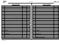
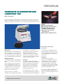
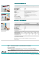
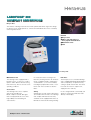
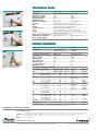
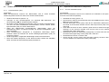
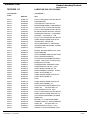
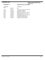
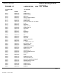
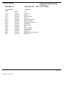
®
Labofuge® 200
SERVICE MANUAL
P/N 12003630
SERVICE
INHALTSVERZEICHNIS
TABLE OF CONTENTS
Sekt.
1
1.1
Titel
Dok.-Nr.
Prospekt
Labo200_DT
2
2.1
2.2
2.3
2.4
2.5
SERVICE
Wartungsplan
Fehlersuchplan
Meßpunkte
Reinigung
Endprüfung
"
"
"
"
"
3
3.1
3.2
FUNKTIONSBESCHREIBUNG
Allgemeine Beschreibung der Baugruppen
Funktionen der Hauptplatte
" -"
" -"
4
4.1
4.2
4.3
4.4
4.5
4.6
4.7
SCHALTPLÄNE
Blockschaltbild
Stromlaufplan
Klemmplan
Bestückungsplan Hauptplatte 28 230V
Schaltbild Hauptplatte 28 230V
Bestückungsplan Hauptplatte 178 120V
Schaltbild Hauptplatte 178 120V
"
"
"
"
"
"
"
5
5.1
5.2
5.3
5.4
5.5
AUSBAUANLEITUNG
Gehäuseteile
Elektrische Komponenten
Antriebskomponenten
Mechanische Komponenten
Service Kit
"
"
"
"
"
6
6.1
6.2
ERSATZTEIL-ABBILDUNGEN UND -LISTE
Explosionszeichnungen
Ersatzteil-Liste
7
8
Seite
Sect.
1
1.1
Brochure
Labo200_E
2
2.1
2.2
2.3
2.4
2.5
SERVICE
Servicing Schedule
Trouble Shooting
Test Points
Cleaning of Instrument Parts
Electrical Safety Check
Labo200_2
2-1/2
2-3/5
2-6
2-7
2-8
"
"
"
"
"
3-1
3-1/2
3
3.1
3.2
FUNCTIONAL DESCRIPTION
Block Functions
Functions of Main Board
" -"
" -"
4-1
4-2/3
4-4
4-5
4-6/8
4-9
4-10/11
4
4.1
4.2
4.3
4.4
4.5
4.6
4.7
DIAGRAMS
Block Diagram
Wiring Diagrams
Wiring Connection Diagrams
Main Board 28 230V - Component Plan
Main Board 28 230V - Wiring Diagram
Main Board 178 120V - Component Plan
Main Board 178 120V - Wiring Diagram
"
"
"
"
"
"
"
5-1
5-2
5-3
5-4
5-5
5
5.1
5.2
5.3
5.4
5.5
DISASSEMBLY OF INSTRUMENT PARTS
Housing / Casing Parts
Electrical Components
Drive Components
Mechanical Components
Service Kit
6
6.1
6.2
SPARE PART FIGURES AND LISTS
Break Down Drawings
Spare Part Lists
Vorbeugende Wartung - Checkliste
7
Preventive maintenance checklist
ÄNDERUNGSNACHRICHTEN
8
TECHNICAL BULLETINS
BETRIEBSANLEITUNG (nicht Teil dieses Manuals)
Ausgabe / Edition: 02
18.01.02 AH
Labo200_2
-"
-"
-"
-"
-"
Labo200_3
Labo200_4
-"
-"
-"
-"
-"
-"
-"
Labo200_5
-"
-"
-"
-"
-"
Labo200_6
6-1/2
Title
Doc.- No.
Page
OPERATING INSTRUCTIONS (not part of this manual)
-"
-"
-"
-"
-"
2-1/2
2-3/5
2-6
2-7
2-8
Labo200_3
3-1
3-1/2
Labo200_4
-"
-"
-"
-"
-"
-"
-"
4-1
4-2/3
4-4
4-5
4-6/8
4-9
4-10/11
Labo200_5
"
"
"
"
"
-"
-"
-"
-"
-"
5-1
5-2
5-3
5-4
5-5
Labo200_6
6-1/2
Labofuge 200
KOMPAKTE KLEINZENTRIFUGE
LABOFUGE® 200
Einfach zu bedienen
Die Heraeus® Labofuge 200 besticht durch funktionelles und elegantes ergonomisches
Design. Der günstige Anschaffungspreis ist ein zusätzliches Plus. Sie lässt sich ideal in
Arztpraxen und kleineren Laboratorien sowie als Stand-by-Gerät in Großlabors einsetzen.
Vorteile
■ einfachste Bedienbarkeit
■ preisgünstiges Komplettsystem
■ vielfältiges Zubehör auch für
medizinische Anwendungen
■ modernste Technik für den
Routineeinsatz
■ wartungsfreier Induktionsmotor
▼
Wartungsfrei
Die Labofuge 200 ist mit einem bürstenlosen
Motor ausgerüstet, so dass ein Auswechseln der Kohlebürsten entfällt. Neben der
Zeit- und Kostenersparnis sind damit auch
saubere Arbeitsbedingungen gewährleistet.
Vielfältiges Zubehör
Die Labofuge 200 wird als komplettes Set
geliefert – einschließlich autoklavierbarem
Rotor.
Aus schlagzähem, glasfaserverstärktem
Kunststoff gefertigt, besitzt dieser Rotor
eine hohe Stabilität und ausgezeichnete
Laufeigenschaften. Er kann einfach und
schnell entnommen und in der LaborSpülmaschine gereinigt werden.
Eine große Auswahl von Adaptern
ermöglicht das Zentrifugieren aller üblichen
Quality Products – Lifetime Care
Röhrchen mit 5, 7, 10 und 15 ml,
einschließlich der vielfach verwendeten
Blutabnahmegefäße „Monovette“,
„Vacutainer“ und „Venoject“. Für Glasröhrchen ist eine spezielle Schutzhülle
vorgesehen, die bei einem Bruch Splitter
und Röhrcheninhalt auffängt.
Sicherheit
Im heutigen Laborbetrieb bergen die
eingesandten Proben oftmals unbekannte
Risiken. Der Benutzer einer Zentrifuge
muss sich daher vor möglicherweise
gefährlichen Aerosolen schützen, die
beispielsweise durch Röhrchenbruch
freigesetzt werden können.
Die Labofuge 200 löst dieses Problem
durch effektive Abdichtung der gesamten
Rotorkammer während des Zentrifugierens.
Die medizinische Kleinzentrifuge
Labofuge 200
Die Labofuge 200 entspricht internationalen Sicherheitsvorschriften und ist mit
Deckelverriegelung und -zuhaltung sowie
einem stahlgepanzerten Schutzmantel
ausgerüstet.
Funktionen
Die mikroprozessorgesteuerte
Labofuge 200 verfügt über helle Leuchtanzeigen und Sensortasten, die das
rasche Einstellen von Geschwindigkeit
und Laufzeit erlauben. Da die zuletzt
eingegebenen Werte gespeichert bleiben,
können Wiederholungsläufe einfach mit
der Starttaste abgerufen werden.
Eine servicefreundliche Selbstdiagnose ist
ebenfalls Bestandteil des Gerätes und
zeigt eine eventuelle Fehlfunktion direkt im
Display an.
TECHNISCHE DATEN
Labofuge 200
Einstellung der Geschwindigkeit
Beschreibung
Maximale Drehzahl (min-1)
Minimale Drehzahl (min-1)
Maximale RZB (x g)
Minimale RZB (x g)
Maximale Kapazität (ml)
Steuerung
Antrieb
Laufzeit
Programmspeicher
Sicherheit
Aufbau
Abmessungen (HxBxT)
Gewicht (inkl. Rotor) (kg)
Leistungsaufnahme (W)
Sensortaste zum Einstellen der
Laufzeit
Mikroprozessorgesteuerte Tischzentrifuge
5300
1600
3030
270
12 x 15
Zeit und Drehzahl mikroprozessorgesteuert
bürstenloser Induktionsmotor, mikroprozessorgesteuert
1 – 99 min und Dauerbetrieb
zuletzt eingegebene Werte werden unbegrenzt
gespeichert
Deckelverriegelung und -zuhaltung, Schutzmantel
schall- und vibrationsdämpfendes Kunststoffgehäuse
Stahlschutzmantel
240 x 284 x 375 mm
ca. 10,7
65
BESTELL-NUMMERN
Gerät
Labofuge 200
Bestell-Nr.
230 V; 50/60 Hz
110-120 V; 50/60 Hz
75003630
75003631
Zubehör für Labofuge 200
Mit der „Start“-Taste können
Wiederholungsabläufe einfach
abgerufen werden
Winkelrotor HFP 5.151)
Max. Drehzahl (min-1)
Max. RZB (x g)
Max. Kapazität (ml)
Max. Radius (cm)
Beschleunigungsdauer (s) 2)
Bremsdauer (s) 2)
75003760
5300
3030
12 x 15
9.65
40
45
Zubehör für Winkelrotor HFP 5.15 1)
Gefäß-Nennmaße (mm)
Nominales Gefäßvolumen
Anzahl der Gefäße pro Rotor
Best.-Nr. Gefäß
Best.-Nr. Adapter
17 x 100 3)
15
12
9080 6)
–
16 x 1003)
15
12
9003 5)
3763 1)
16 x 85 4)
10
12
–
3762
12x 100
7
12
90015)
3227
13 x 75
5
12
–
3227
1) ist im Lieferumfang der Zentrifuge enthalten
2) gemessen bei 230 V
3) Bei Überlänge (Gefäß zwischen 100 und 131 mm) Reduzierung auf max. 6 Stück
4) Bei Verwendung von Sarstedt „Monovette“-Gefäßen, Länge inkl. Kappe 117 mm, Reduzierung auf max. 6 Stück
5) Borosilikat-Glas
6) Polypropylen-Röhrchen
Ihr Partner
Ihr Kontakt in Deutschland – Berlin, Düsseldorf, Gera, Hamburg, Hanau, München, Nürnberg, Stuttgart
Vertrieb
Kendro Laboratory Products GmbH · Tel. 01805-536 376 · Fax 01805-112 114 · [email protected]
Service
Kendro Laboratory Products GmbH · Tel. 01805-112 110 · Fax 01805-112 114 · [email protected]
Europa, Naher Osten und Afrika
Kendro Laboratory Products International Sales · Hanau · Tel. +49 (6181) 35-300 · Fax +49 (6181) 35 59 44 · [email protected]
Asien Pazifik Kendro Laboratory Products (H.K.) Limited · Hong Kong · Tel. +852 2711-3910 · Fax +852 2711-3858 · [email protected]
USA, Kanada, Lateinamerika
Kendro Laboratory Products International Sales · Newtown · Tel. +1 (203) 270-2080 · Fax +1 (203) 270-2210 · [email protected]
http://www.kendro.de
Kendro Laboratory Products – Ein internationales Unternehmen, hervorgegangen aus der Fusion von Heraeus Instruments und Sorvall.
Für Kontakte mit weiteren internationalen Niederlassungen setzen Sie sich bitte mit der internationalen Vertriebsorganisation von Hanau, Hongkong oder Newtown in
Verbindung. Abweichungen von den in dieser Information enthaltenen Abbildungen und technischen Daten bleiben vorbehalten.
Printed in Germany – 3C 01/00 VN 4t Künzel
ZF LF200 3d
Internet
LABOFUGE® 200
COMPACT CENTRIFUGE
Easy to Use
The Heraeus® Labofuge 200 is functional and sophisticated with an ergonomic design.
It is ideal for use in medical practices, clinical and small laboratories and as a stand-by
unit in large laboratories.
Benefits
■ Easy to Use
■ Able to run wide range of
most popular medical tubes
■ Maintenance free
■ Safe
▼
Maintenance free
The Labofuge 200 is equipped with a
brushless motor, so there is no need to
replace carbon brushes. Beside saving
time and money, this also ensures clean
operating conditions.
Accessories
The Labofuge 200 comes complete
with an autoclavable rotor.
Made of impact resistant, fibre glass
reinforced polyamide, this rotor offers
high stability and outstanding run
characteristics.
Quality Products – Lifetime Care
Labofuge 200
It is easily removed for cleaning in the
laboratory washing machine. An extensive
range of adapters permits centrifugation
of all standard 5, 7, 10 and 15 ml tubes,
including the popular “Monovette”, “Vacutainer” and “VenoJect” blood collection
tubes.
Functions
The microprocessor controlled Labofuge
200 is equipped with bright digital displays
and touch-pad keys for quick and easy
setting of speed and run-time. The values
last used are stored. To repeat a run,
simply press the start key.
Safety
Samples processed in today’s laboratories
often harbor unknown risks. The Labofuge
200 complies with international safety
standards and is equipped with a lid lock,
lid interlock and steel armoured guard ring.
It is also designed with a user friendly self
diagnosis system which indicates faults
directly on the display.
TECHNICAL DATA
Set the required speed…
Labofuge 200
230 V version
Description
Maximum speed (rpm)
Minimum speed (rpm)
Maximum RCF (x g)
Minimum RCF (x g)
Maximum capacity (ml)
Controller
Drive
Runtime
Program memory
Safety
Design
Microprocessor controlled table top centrifuge
5300
5000
1600
1600
3030
2600
270
270
12 x 15 (glass)
12 x 15 (glass)
Microprocessor controller for time and speed
Brushless induction motor, microprocessor controlled
1-99 min. and continuous operation (Hold)
Stores values last entered, unlimited
Lid lock and lid interlock, steel armoured guard ring
Fibre glass reinforced polyamide housing with high noise and
vibration insulation properties
240 x 284 x 375 / 9.5 x 11.2 x 14.8
Approx. 10.7 / 23.5
Approx. 10.7 / 23.5
65
65
Dimensions (H x W x D) (mm / inch)
Weight (incl. rotor) (kg / Ibs)
Power consumption (W)
110-120 V version
ORDER NUMBERS
…and set the required time
Model
Order No.
Labofuge 200
230 V; 50 / 60 Hz
110-120 V; 50 / 60 Hz
75003630
75003631
Accessories for Labofuge 200
230 V version
110-120 V version
75003760
5300
3030
12 x 15
9.65
40
45
75003760
5000
2600
12 x 15
9.65
40
45
1)
Angle rotor
Max. speed (rpm)
Max. RCF (x g)
Max. capacity (ml)
Max. radius (cm)
Acceleration time (sec)
Braking time (sec)
With the “start” button, repeat
runs can easily be recalled
Accessories for angle rotor 75003760
Tube volume Type of tube
(ml)
Dimension (mm)
Diam. x Length
Tubes
per rotor
Type of
adapter
Adapter
Order No.
7
15
3-5
Glass tubes (DIN)
Glass tubes (DIN)
VenoJect II (Terumo)
12
16
13
100
100
75
12
12
12
yellow
4)
75003227
–
75003227
7
9-10
3-5
VenoJect II (Terumo)
VenoJect II (Terumo)
Vacutainer (BD)2)
13
16
13
100
100
75
12
12
12
7
7
Vacutainer (BD)2)
Vacutainer (BD)
13
16
100
75
12
12
10
15
4
5
7.5
9
12 (Urine)
Urine tubes
Vacutainer (BD)2)
Vacutainer (BD)
Sarstedt Monovette
Sarstedt Monovette
Sarstedt Monovette
Sarstedt Monovette
Sarstedt Monovette
BD, Terumo
16
16
11.5
13
15
16.5
16.5
16
100
125
83.5
90
92
92
101.5
100
12
6
12
12
12
6
6
12
1)
cream +
rubber pad
yellow
sleeves
cream +
rubber pad
yellow
sleeves +
rubber pad
75003227
750037633)
75003227
75003227
750037633)
75003266
–
–
75003227
75003227
–
75003762
–
750037633)
4)
4)
cream
cream
4)
rubber pad
4)
sleeves
3)
2) tube incl. Hemoguard cap
included with centrifuge
included with rotor
The adapter set 75003227 will contain the yellow and cream adapters and rubber pads.
4)
not necessary
For Ordering or Technical Information
Internet
http://www.kendro.com
Quality Products – Lifetime Care
Registered to ISO 9001. Kendro Laboratory Products meet or exceed stringent quality and product safety standards: CE for the European Union, and UL, cUL or
CSA standards for North America. ©2000 Kendro Laboratory Products. All Rights Reserved.
Printed in Germany 15C 03/00 VN 4t Künzel
ZF LF200 3e
Asia Pacific
Kendro Laboratory Products (H.K.) Limited · Hong Kong · Tel. +852 2711-3910 · Fax +852 2711-3858 · [email protected]
Europe, Middle East, Africa
Kendro Laboratory Products International Sales · Hanau · Germany · Tel. +49 (6181) 35-300 · Fax +49 (6181) 35 59 44 · [email protected]
Latin America Kendro Laboratory Products International Sales · Newtown · USA · Tel. 1 (203) 270-2080 · Fax. 1 (203) 270-2210 · [email protected]
USA
Kendro Laboratory Products · Newtown · Tel. 1 (800) 522-7746 · Fax. 1 (203) 270-2166 · [email protected]
SERVICE
2.1 Wartungsplan (jährliche Durchführung empfohlen)
2.1.1 Routinemäßige Wartung ohne Zerlegung der Zentrifuge
2.1.1.1 Elektrische Installations- und Sicherheitsüberprüfung
• Netzstecker ziehen, Spannungsversorgung und Netzabsicherung überprüfen
(16 A K-Sicherungsautomat)
• Stecker und Steckdose überprüfen - defekte Teile ersetzen (lassen)
• Zustand des Netzkabels überprüfen und ggf. ersetzen
2.1 Servicing Schedule (yearly procedure recommended)
2.1.1 Maintenance Routine without Dismantling the Centrifuge
2.1.1.1 Electrical Installation and Safety
• Switch OFF the centrifuge and disconnect the unit from power, check voltage
supply and mains fusing (16 Amps, slow blow characteristic)
• Check condition of plug and wall socket - (let) replace defective parts
• Check cord condition and fixing / connection - replace or refit it
2.1.1.2 Anforderungen an den Aufstellort
• Unterbau (Fußboden, Tisch, Rollwagen mit Feststellrädern o.ä.) auf vibrationsfreien und stabilen Zustand hin überprüfen
• Stellplatz auf gute Belüftung und genügendem Abstand zu Wänden oder benachbarten Geräten hin überprüfen, direkte Sonneneinstrahlung vermeiden
• Zentrifuge waagerecht ausrichten - z.B. mit einer Dosenlibelle
2.1.1.2 Location and Mechanical Installation
• Check the base (ground, table, lorry with lockable wheels etc.) For resonancefree and stable conditions
• Check for a well ventilated place and sufficient distances to walls or adjacent
equipment, without exposure to direct sunlight
• Check the leveling of instrument (use a spirit level)
2.1.1.3 Deckel-Verriegelungsmechanismus und –Sicherheit
• Zentrifuge mit elektrischer Spannung versorgen
• Festes Schließen und selbsttätiges Öffnen des Deckels überprüfen - Korrektur
durch Einstellung des Deckels und/oder des Deckelschlosses)
• Deckel-Dichtungsring überprüfen und im Schadensfall austauschen
• Zur Überprüfung des Sicherheit: Zentrifuge starten, kurz laufen lassen und
stoppen. Der Deckel darf beim Drücken der „Deckel auf“-Taste solange nicht
entriegelt werden, bis die “end” Meldung im Drehzahlfeld erscheint - im
Fehlerfall ist die Hauptplatte auszutauschen
2.1.1.3 Lid Locking Mechanism and Safety
• Connect the centrifuge to power and switch ON
• Check for easy lid closing and self-acting lid opening - if in disorder, readjust
lid’s swivel hinge and/or lock assembly
• Check the central rubber gasket for lid sealing and replace it, if damaged
• For checking the safety: start the centrifuge, let it shortly run and stop it, the lid
must not be unlocked by the microprocessor until the “end” message is shown
on the display - if safety circuit is out of function, replace the main board
2.1.1.4 Cleanliness of Spin Chamber and Motor Casing
• Open the lid and remove the rotor (for loosening turn the central winged nut anti
clockwise from the motor shaft)
• Clean the spin chamber with a dry and absorbent cloth (remove all dust and
moisture - see also 2.5 Cleaning)
• Check the cleanliness of the motor casing and take care of the annular slot
around the motor shaft: penetrating fluids can damage the upper motor
baring, remove fluids with an injector and/or absorbent paper
2.1.1.4 Reinigung von Rotor-Kammer / Motor-Gehäuse
• Deckel öffnen und Rotor ausbauen (zum Lösen: Zentrale Flügelmutter durch
Linksdrehen von der Antriebswelle lösen)
• Zur Reinigung der Rotor-Kammer ein trockenes und saugfähiges Tuch
verwenden (Schmutz und Feuchtigkeitsrückstände müssen entfernt werden)
• Auf Sauberkeit des Motor-Gehäuses (um die Motorwelle herum) ist zu achten das Eindringen von Flüssigkeiten führt zur Beschädigung des oberen
Motor-Lagers. Flüssigkeiten mit Spritze oder saugfähigem Tuch entfernen.
2.1.1.5 Rotor and Accessories Condition and Sealing
• Check the condition of rotors and accessory parts (especially all supporting or
stressed partitions): the rotor and/or accessory parts must not be used any
longer, if there are visible traces of mechanical damage
2.1.1.5 Rotor- und Zubehör-Zustand und -Dichtung
• Überprüfung des Zustandes von Rotor- und Zubehör-Teilen (insbesondere alle
tragenden oder stark beanspruchten Teile): Rotor- und/oder Zubehör- Teile
dürfen nicht länger benutzt werden, falls dort sichtbare Spuren von Rissen
erkennbar sind
Ausgabe / Edition: 03
18.04.02 AH
2-1
Labofuge 200
SERVICE
Wartungsplan
Servicing Schedule
2.1.1.6 Rotor-Befestigung und Motor-Welle
• Rotor-Befestigungsmutter auf einwandfreien Zustand hin überprüfen und im
Zweifelsfall ersetzen
• Hochleistungsrotoren aus Kunststoff besitzen eine begrenzte Lebensdauer. Aus
Sicherheitsgründen sind sie nach 5 Jahren Gebrauchsdauer oder 10000
Arbeitszyklen auszutauschen. Das Verfallsdatum (expiry date) ist an der
Datumsuhr in der Rotorunterschale zu erkennen. Die 2stellige Nummer im
Zentrum steht für die Jahreszahl und der Pfeil weist auf den Verfallsmonat.
Durch gleichzeitiges Betätigen der beiden „set“ Tasten kann bei geschlossenem
Deckel überprüft werden, wieviel Arbeitszyklen für den vorhandenen Rotor noch
möglich sind. Die Anzeige erfolgt im Drehzahlfeld.
• Motor-Welle auf evtl. Beschädigungen untersuchen: die Zentrifuge darf nicht
weiter benutzt werden, wenn die Antriebswelle beschädigt ist (z.B. verbogen,
Gewinde abgenutzt, waagerechte Riefen)
2.1.1.6 Rotor Fixing and Motor Shaft
• Check the trouble-free condition of the locking nut and replace it in case of
malfunction
• High performance rotors made of plastic have a limited service life. Due to
safety reasons they have to be exchanged after 10,000 cycles or after being in
use for five years. The expiry date can be seen on the date clock in the rotor
lower shell. The two-digit number in the middle represents the year and the
arrow points to the expiry month. The number of cycles may be checked at any
time by closing the lid and keeping both “set” keys pressed. The accumulated
rotor cycles will be displayed in the speed display.
• Check the condition of the drive motor shaft: the centrifuge must not be used
any longer, if the drive shaft is damaged (bend, thread is worn out, horizontal
grooves etc.)
2.1.1.7 Temperaturentwicklung
• Lüftungsschlitze hinten unter dem Deckel und unter der Bodenplatte auf Durchlässigkeit überprüfen - bei nicht ausreichendem Luftdurchsatz steigt die
Temperatur von Rotor, Motor und Elektronik unzulässig hoch an
2.1.1.7 Temperature Level
• Check the air inlet underneath the lid and under the bottom plate for free
ventilation, insufficient air flow will lead to temperature rise of rotor, motor and
electronic parts
2.1.2 Routinemäßige Wartung nach Zerlegung der Zentrifuge
2.1.2.1 Motor-Dämpfungselemente
• Überprüfung der Motor-Gummipuffer (verstärkter Gummiabrieb, Unwuchthäufigkeiten): Ersatz bei schlechtem Zustand oder spätestens nach einem Zeitraum
von 3 Jahren
2.1.2
2.1.2.1 Motor Supporting Elements
• Check the supporting and damping elements of the drive motor and replace
them in case of increased rubber abrasion or abundance of imbalance but at
least every 3 years
2.1.2.2 Bremsschaltung
• Bremsfunktion überprüfen (gleichmäßiger Bremseffekt)
2.1.2.2 Braking Circuit
• Check the function of the braking circuit (even brake effect)
2.1.2.3 Leitungen und Schraubbefestigungen
• Schraub- und Steck-Anschlüsse aller Leitungen an sämtlichen Leiterplatten und
Bauteilen auf guten Kontakt hin überprüfen und ggf. korrigieren bzw. defekte
Teile ersetzen
• Alle Schraubverbindungen sämtlicher Leiterplatten sowie mechanischer und
elektrischer Bauteile auf festen Halt hin überprüfen und ggf. korrigieren bzw.
defekte Teile ersetzen (Schraubensicherungslack verwenden)
2.1.2.3 Lead and Screwing Connection
• Check the terminal and plug connections of all leads and on all boards and
electrical components, tighten all loosen screwing connections, refit or replace
defective parts
• Check the screwing connections of all boards, mechanical and electrical
components and re-tighten them if necessary (use screw locking lac for motor
mounts and lid lock assembly)
2.1.2.4 Schutzleiter und Erdungsverbindungen
• Schutzleiter und alle Erdungsverbindungen auf Durchgang prüfen
• Isolationswiderstand und Körperstrom messen
Ausgabe / Edition: 03
18.04.02 AH
Maintenance Routine after Dismantling the Centrifuge Casing
2.1.2.4 Protection Earth Core and Grounding Connections
• Check the protection earth core for continuity and all grounding plug connectors
• Check isolation resistance and accessible current (see 2.5)
2-2
Labofuge 200
SERVICE
2.2
Fehlersuchplan
Anzeige
Verhalten
Displays
bleiben
dunkel
Ursache
Fehlende
Netzspannung
Keine Niederspannungsversorgung
MotorÜbertempera
-turschalter
hat ausgelöst
Displays
leuchten,
aber
Antrieb
startet
nicht
Rotor läßt
sich nicht
drehen
2.2
mögliche
Fehlerquellen
Netzsicherung
ausgefallen
Netzkabel defekt
Gerätesicherung F1
oder F2 auf der
Hauptplatte defekt
Defekte Verbindung
zwischen Anzeigenund Leistungsteil
Defekter Anzeigenoder Leistungsteil
Motortemperatur
größer als 120°C
Rotor ist blockiert
Motor sitzt fest
fehlerhafte Leitungen,
Kontakte
Motor läuft
nicht an
Motor defekt
Kondensator defekt
Hauptplatte defekt
Antrieb
macht
Geräusche,
schlechtes
Trennergebnis
Mechanisch
Elektrisch
Ausgabe / Edition: 03
18.04.02 AH
Verschleiß der
Antriebsdämpfung
Motorlager
Klemmen, Zuleitung
oder Motorwicklung
Ansteuerung defekt
Trouble Shooting
Error
Indication
Abhilfe
Error Cause
Sicherung überprüfen und ggf.
wieder einschalten
No mains
voltage
supply
Netzkabel überprüfen und ggf.
ersetzen
Displays
remain
dark
Sicherung austauschen, bei
erneutem Ausfall die
Hauptplatte ersetzen
Verbindungsleitungen
überprüfen ggf. Hauptplatte
komplett ersetzen
No low
voltage
supply
Hauptplatte komplett ersetzen
Motor overtemperature
switch has
tripped
Thermoschalter im Motor
nach Abkühlung auf
Durchgang prüfen
Leichtgängigkeit überprüfen,
blockierende Gegenstände
entfernen
Motor ersetzen
Schraubkontakte, Leitungen
zum Motor prüfen und ggf.
ersetzen
Wicklungswiderstände prüfen
und defekten Motor ersetzen
Kondensator ersetzen
Hauptplatte komplett
ausbauen und ersetzen
Motordämpfungselemente
austauschen
Motor austauschen
Spannungen an den Motorklemmen messen, defekte
Teile austauschen
Hauptplatte austauschen
Displays
are
illuminated,
but drive
doesn’t
start
Rotor didn’t
turn
Possible Error
Source
Mains fuse or circuit
breaker failed
Defective mains cord
Defective unit fuse or
fuses on main board
Faulty connection
from indication to
power board
Replace main board
Motor temperature is
higher than 120°C
Let motor cool down, then
check temperature switch and
leads with Ohmmeter
Rotor is jammed
Check for easy rotor
movement, remove any
jamming objects
Connections inter
drive and main board
Defective drive
Faulty condenser
Faulty main board
Drive
makes
noises-no
good
separation
result
2-3
Mechanics
Electrical
Check fuse or circuit breaker,
replace or switch on again
Check instrument cord,
replace defective parts
Replace it, if fuse blows again,
disconnect electrical parts,
otherwise replace main board
Check connections on CPU,
indicat. Board and connecting
leads, replace defective parts
Faulty indication or
power board
Motor is jammed
Motor didn’t
start
Corrective Procedure
Wear out of motor
rubber mount
Motor bearing
Defective terminal
connecton, faulty lead
or motor winding
Defective driving
Replace motor
Check terminal and lead
connections, replace faulty
parts
Check resistance of motor
windings, replace faulty parts
Replace condenser
Remove main board
completely and replace it
Replace motor rubber mounts
Change motor completely
Check voltage on motor terminal and winding resistances
-see test points on boards
Replace main board
Labofuge 200
SERVICE
Trouble Shooting
Fehlersuchplan
Anzeige
Verhalten
Antrieb
bremst
nicht
Deckel läßt
sich im
Stillstand
nicht mit
Tastendruck
öffnen
„LId“
Anzeige im
Drehzahlfeld
Error Cause
Possible Error
Source
Corrective Procedure
No brake
current
Faulty main board
Remove main board
completely and replace it
Lid coil is not
or not
sufficiently
supplied with
voltage
Missing mains
voltage
PTC resistor has
released
Faulty driving or triac
circuit
Remedy see above, manual
opening only at standstill
After a waiting time of 1-2
minutes press key again
Replace the complete main
board
Faulty lid coil
Faulty winding of coil
Lid bolt is jamming
Deckel seitlich ausrichten
Lid is not
correctly
locked
Replace complete lid lock
Push lid into lock and press
the key again
Deckel sofort schließen! Netz
AUS/EIN, Bremsphase („br“)
abwarten bis end Meldung
erscheint
Lid was
opened
manually
during run
Ursache
mögliche
Fehlerquellen
Abhilfe
Kein
Bremsstrom
vorhanden
Fehler auf der
Hauptplatte
Hauptplatte austauschen
Deckelspule
erhält keine
oder zu
wenig
Spannung
fehlende Netzspannung
PTC-Widerstand hat
ausgelöst
Ansteuer- od. Triacschaltkreis defekt
Abhilfe siehe oben,
Notöffnung nur im Stillstand
Taste nach 1-2 Minuten
erneut drücken
Hauptplatte komplett
austauschen
Deckelspule
Spule defekt
Deckel ist
nicht richtig
eingerastet
Deckellasche klemmt
Deckelschloß austauschen
Deckel ins Schloß drücken,
Taste erneut betätigen
Deckel ist verspannt
oder falsch justiert
Deckel wurde
manuell geöffnet
Verbotener Eingriff!
Notöffnung nur im
Stillstand betätigen
Stromkreis
für
Umrichterversorgung
während des
Laufs unterbrochen
Deckelschalter oder
Leitungen zeitweise
unterbrochen
(Wackelkontakt)
Leitungen zum Deckelschalter
prüfen, bei defektem
Mikroschalter Deckelschloß
komplett austauschen
„OPEn“
Anzeige
im Drehzahlfeld
15V Stromkreis im
Stillstand
unterbrochen
Deckelschalter oder
Leitungen
unterbrochen
Leitungen, Schalter prüfen,
bei defektem Mikroschalter
Deckelschloß komplett
austauschen
„br “
Anzeige
im Drehzahlfeld
Gerät kommt
ungebremst
zum
Stillstand
kurzzeitige
Netzunterbrechung
Stillstand des Rotors (ca.75
sek.) abwarten, neu Starten
Ausgabe / Edition: 03
18.04.02 AH
Error
Indication
Drive
doesn’t
decelerate
Lid cannot
be opened
by key
pressure at
standstill
“LId“
message
appears in
speed
display
“OPEn“
message
in speed
display
“br “
message
appears in
speed
display
2-4
Lid is deformed or
disadjusted
Forbidden intervention
Emergency opening
can only be used at
standstill
Readjust the lid centrically
Close lid immediately, turn
power off/on, wait for
termination of br phase until
end message appears
Protection
circuit (15V)
for lid control
was
interrupted
during the
run
Defective micro
switch or leads or
connectors to micro
switch are interrupted
Check leads and connectors
to micro switch, in case of a
faulty micro switch, replace lid
lock device completely
15V supply
circuit is
interrupted at
standstill
Defective micro
switch or leads or
connectors to micro
switch are interrupted
Check leads and micro switch
Rotor comes
to standstill
without
braking force
Short interruption of
mains supply
Wait for rotor standstill (appr.
75 seconds) and re-start
Labofuge 200
SERVICE
Fehlersuchplan
Trouble Shooting
Anzeige
Verhalten
Ursache
mögliche
Fehlerquellen
Abhilfe
„E-“„ 2“
Anzeige im
Drehzahlfeld
Wartungszähler
abgelaufen
Rotor hat 10000
Arbeitszyklen erreicht
Rotor, NV-Ram und
Gummipuffer ersetzen
(Service Kit)
„E-“„ 3“
Anzeige im
Drehzahlfeld
Kein
Bremsstrom
vorhanden
Fehler auf der
Hauptplatte
Defekte Hauptplatte komplett
ersetzen
NV-RAM ist nicht
initialisiert oder falsch
NV-RAM und Sockel prüfen,
korrektes NV-RAM einsetzen
„E-“„12“
Anzeige im
Drehzahlfeld
Prüfsumme
im NV-RAM
ist falsch
Fehler bei
der
Datenübernahme aus
dem NVRAM
Fehler auf der
Hauptplatte
Defekte Hauptplatte komplett
ersetzen
Alle
Dezimalpunkte
leuchten
Wartungszähler
abgelaufen
Rotor hat 10000
Arbeitszyklen erreicht
Rotor, NV-Ram und
Gummipuffer ersetzen
(Service Kit)
Ausgabe / Edition: 03
18.04.02 AH
Error
Indication
„E-“„ 2“
message
appears in
speed
field
„E-“„ 3“
message
appears in
speed
field
„E-“„12“
message
appears in
speed
field
All dots in
the display
are
illuminated
2-5
Error Cause
Possible Error
Source
Corrective Procedure
Maintenance
counter
expired
Rotor has reached
10000 cycles
Replace rotor, NV-Ram and
motor supports (Service Kit)
No brake
current
Faulty main board
Remove main board
completely and replace it
Checksum
error of NVRAM
NV-RAM is not
initialized or false
Check NV-RAM and socket,
insert the correct NV-RAM
Disturbed
data transfer
from NVRAM
Faulty main board
Remove main board
completely and replace it
Maintenance
counter
expired
Rotor has reached
10000 cycles
Replace rotor, NV-Ram and
motor supports (Service Kit)
Labofuge 200
SERVICE
2.3
Meßpunkte
2.3
Meßpunkte
Meßwert
Netzklemme XA
230V AC
Deckelschalter
Stecker XB
320V DC
Klemme XC
Motorspannung
Motorstrom IM
Motorwicklungswiderstand 20°C
-Isolationswert
Deckelmagnet
Klemme XD
Ausgabe / Edition: 03
18.04.02 AH
ca.
58V AC
105V AC
120V AC
80V AC
75V AC
ca. 1,2A
ca. 1,2A
ca. 0,8A
ca. 3,3A
ca. 2,0A
14,6Ω
14,6Ω
> 10MΩ
105Ω
Voraussetzungen
Alle angegebenen Strom-/ Spannungswerte sind
auf 230V Netzspannung (±10%) bezogen
Test Points
Test Points
Mains terminal XA
Lid micro switch
Plug XB
Spannungsabfall bei offenem Deckel
Rotor #3760 unbeladen, jeweils gemessen nach
Erreichen der Solldrehzahl
-1
1600min
-1
4000min
-1
5300min
zu Beginn der Bremsphase
am Ende der Bremsphase
Rotor #3760 unbeladen, jeweils gemessen nach
Erreichen der Solldrehzahl mit Weicheisen(1,5%) od. Effektivwert-Meßinstrument
-1
1600min
-1
4000min
-1
5300min
kurzzeitig bei max. Beschleunigung
kurzzeitig bei max. Bremsung
Gerät ausschalten und Motor abklemmen
Hauptwicklung (sw – gn)
Hilfswicklung (sw – ge)
jeder Leiter gegen Stator-Gehäuse gemessen
Gerät ausschalten,
Wicklungstemperatur 20°C
Terminal XC
Motor voltage
Motor current IM
Motor windings
resistance 20°C
-insulation value
Lid solenoid
terminal XD
2-6
Unit value
230V AC
120V AV
320V DC
160V DC
approx.
58V AC
105V AC
120V AC
80V AC
75V AC
approx.
1,2A
1,2A
0,8A
3,3A
2,0A
14,6Ω
14,6Ω
> 10MΩ
105Ω
29Ω
Conditions
All given voltage and current values refer either
to 230V (±10%) or 120V (±10%)
Voltage drop by open lid at 230V units
Voltage drop by open lid at 120V units
Rotor #3760 not loaded, in each case measured
after reaching the selected speed
1600rpm
4000rpm
5300rpm
at the beginning of the braking phase
at the end of the braking phase
Rotor #3760 not loaded, in each case measured
after reaching the selected speed with a soft iron
or digital effective measuring instrument
1600rpm
4000rpm
5300rpm
maximum during acceleration
maximum during braking phase
switch OFF unit, pull off motor plug
mains winding (black – green)
auxiliary winding (black – yellow)
resistance inter each phase and motor casing
switch OFF unit,
resistance at 20°C (68°F) at 230V units
resistance at 20°C (68°F) at 120V units
Labofuge 200
SERVICE
2.4
Reinigung
2.4
Cleaning of Instrument Parts
ACHTUNG - WARNUNG!
Keine elektrischen oder elektronischen Bauteile mit feuchten Reinigungsmitteln säubern!
ATTENTION - WARNING!
The electrical and electronic components must not be cleaned with moist
detergents!
Zur Reinigung und Pflege der Gehäuseteile und des Zubehörs
Gebrauchsanweisung in Sektion 1 Abschnitt Wartung und Pflege.
siehe
For Cleaning the centrifuge housing or its accessories see Operating Instructions
section 1 (maintenance and care).
• Elektronik Baugruppen
Verstaubte Platinen vorsichtig mit einem trockenen und weichen Pinsel reinigen
und losen Staub absaugen
• Luftschlitze
Verschmutzte Luftschlitze in der Frontblende oder in der Bodenplatte mit einer
Bürste reinigen und losen Schmutz absaugen
• Electronic components
Clean dusty components carefully with a dry and soft brush and remove loose
dust with a vacuum cleaner
• Vent holes
Remove dirt from vent holes of front panel or bottom plate using a brush and
vacuum cleaner
Ausgabe / Edition: 03
18.04.02 AH
2-7
Labofuge 200
SERVICE
2.5
Endprüfung
2.5
Electrical Safety Check
ACHTUNG!
Eine Endprüfung muß nach jeder Wartung und/oder Reparatur durchgeführt
werden!
ATTENTION!
A final electrical safety check must be performed after each maintenance
and/or repair!
• Schutzleiterwiderstand prüfen
Zwischen Netzstecker-Schutzleiter und den Schutzleitern des Motors, des
Elektronik-Chassis und des Gehäusebodens darf der Meßwert nicht über 200
mΩ liegen.
• Isolationswiderstand prüfen
Prüfen Sie ebenfalls den Isolationswiderstand zwischen den Netzsteckerpolen
und dem Schutzleiter; er muß größer als 2 MΩ sein.
• Körperstrom nach EN 61010 messen
Der Körperstrom darf im Fehlerfall (unterbrochener Schutzleiter) nicht größer sein
als 3,5 mA! In Anlehnung an EN61010, IEC1010 und UL3101 läßt sich mit
nachfolgender Meßschaltung ein solcher Fehlerfall nachbilden.
• Resistance check of protective conductor
The measuring value of the resistance between the mains plug's grounding pin
and the grounding conductors of the motor, electronic chassis and the casing
must not exceed 200 mΩ.
• Insulation resistance Check
Check also the insulation resistance between the poles of the mains plug and the
grounding conductor; the resistance value must be more than 2 MΩ.
• Accessible current measured to EN 61 010
The accessible current must not exceed 3.5 mAmps in single fault condition
(interrupted protection earth wire)! In accordance with the EN61010, IEC1010
and UL3101 such a fault condition can be reproduced by the following measuring
circuit.
Steckergehäuse / plug-in casing
0,22µF
±5%
0,022µF
±5%
N (L)
PE
Ausgabe / Edition: 03
18.04.02 AH
V
AC
Specifaction for the meter
- TRMS, DC - 5kHz or more
- Input resistance > 1MΩ
- Tolerance 5% or better
- Crest Factor 5 or better
500Ω
±1%
L (N)
Spezifaktionen für Meßgerät
- TRMS, DC - 5kHz oder mehr
- Eingangswiderstand > 1MΩ
- Toleranz 5% oder besser
- Crest Faktor 5 oder besser
10kΩ
±5%
Körperstrom:
accessible current: I [mA] = U [mV] / 500:
Umax = 1750mV ≡ Imax = 3,5mA
2-8
Labofuge 200
FUNKTIONSBESCHREIBUNG
FUNCTIONAL DESCRIPTION
3.1 Allgemeine Beschreibung der Baugruppen
Die Labofuge 200 ist eine mikroprozessorgesteuerte Laborzentrifuge mit Induktionsmotor und integrierter Luftkühlung.
Das Gerät enthält die folgenden Baugruppen (siehe Blockschaltbild 4-1):
· Hauptplatte 28 (für 230V Netzversorgung) mit Mikroprozessorteil und
Leistungselektronik, Absicherung erfolgt zweipolig über F1 und F2 (6,3 AT)
· Tasten- und Anzeigenplatte (Programmierung: MEGACONTROL einfach), Teil
der Hauptplatte
· Einphasen-Induktionsmotor mit Kondensator und integriertem Übertemperaturschalter (125°C)
· Zweifache Deckelverriegelung (mechanische Zuhaltung, magnetische
Entriegelung) mit integriertem Mikroschalter, eingebaut unter dem Gehäuse
vorne rechts und links und innen an der Kesselwand befestigt
3.1 Block Functions
The Labofuge 200 is a microprocessor controlled laboratory tabletop centrifuge with
induction drive motor and integrated air cooling system.
The unit incorporates following boards and components (see block diagram 4-1):
· Main board 28 (for 230 V mains supply) or main board 178 (for 120 V mains
supply) with microprocessor part and power electronics
· Key and indication board (programming: MEGACONTROL simple), part of the
main board
· 1 phase induction motor with phase shift capacitor and integrated thermal over
temperature switch (C. O. 125°C)
· Double lid lock assembly with solenoid and integrated micro switch (mechanical
bolt keeper, magnetically dislocking), attached in front on both sides of the
vessel
3.2 Funktionen der Hauptplatte
Die Hauptplatte 28 ist komplett hinter der Frontblende montiert. Die Bauteile auf der
Hauptplatte sind in folgende Funktionsgruppen aufgeteilt (siehe Stromlaufplan 4-2):
· Sicherungen der Hauptplatte (2 x 6,3 AT)
· Funkentstörung gemäß EN 55011
· Netzteil für Versorgung des Prozessorteiles und der Leistungselektronik
(potentialgetrennt)
· Triacansteuerung für Deckelmagneten ( DC-Versorgung über Diodenbrücke)
· Diodenbrücke für die Zwischenkreisspannung zur Speisung des Frequenzgenerators und des Bremskreises
· Mikroprozessorteil mit Controller (CPU)
· Austauschbares NV-RAM mit zentrifugenspezifischen Daten
3.2 Main Board Functions
The main board 28 / 178 is mounted completely behind the front panel. The
components on main board are arranged in following groups (see wiring diagram
page 4-2).
· Board fusing (2 x 6.25 / 6,3 Amps. slow blow feature)
· Noise filter in accordance with EN 55011
· Power pack for low voltage supply of microprocessor part and power
electronics (potential separated by transformer)
· Triac control circuit for lid solenoid ( DC supply via bridge rectifier)
· Bridge rectifier for DC intermediate circuit supplying brake path and frequency
converter
· Microprocessor part with CPU
· Exchangeable NV-RAM containing specific data of the unit
3.2.1 Netzteil
Das Netzteil besteht aus Trafo, Gleichrichter und Spannungsregler und liefert:
U1 = 5 V
für die Versorgung von Microprozessor, Tasten- und Anzeigenelemente Bezugspotential: Schutzleiter (GND)
3.2.1 Power Pack
The power pack (transformer, bridge rectifier and voltage regulator) generates:
U1 = 5V:
supplies central processor, key and indication board
reference potential: protective conductor (GND)
3.2.2 Zwischenkreisspannung mit Bremszweig und Frequenzgenerator
Der Zwischenkreis dient als Energiepuffer zwischen der pulsierenden Eingangsleistung des Netzes und der abgegebenen Motorleistung. Er ist als Gleichspannungszwischenkreis mit Gleichrichter (Diodenbrücke) und Glättungskondensatoren aufgebaut. Der Zwischenkreis ist vor Überspannungen geschützt.
3.2.2 Intermediate Circuit with Brake Path and Frequency Converter
The DC intermediate circuit serves as an energy store between the AC power input
and the transmitted motor performance. The intermediate circuit consists of a bridge
rectifier (4 diodes) and two serial connected reservoir capacitors. The intermediate
circuit is over voltage protected.
Ausgabe / Edition: 02
16.01.02 AH
3-1
Labofuge 200
FUNKTIONSBESCHREIBUNG
FUNCTIONAL DESCRIPTION
Bremszweig
Zum Bremsen des Zentrifugenantriebs wird der Induktionsmotor mit
Gleichspannungspulsen (Wirkung wie Frequenz Null) aus dem Zwischenkreis
beaufschlagt. Die Pulsfolgefrequenz wird abhängig von der Bremszeit
(entsprechend der Drehzahl) verändert, wodurch sich ein veränderter
Geräuschpegel ergibt.
Brake Path
To braking the centrifugal drive the induction motor is supplied with DC pulses from
the intermediate circuit (affects as frequency zero). The pulse frequency is variable
in dependance of the braking time (equal to speed), as a result of which the noise
level is changed.
Frequenzgenerator
Der Frequenzgenerator liefert für den Antriebsmotor eine Rechteckspannung mit
veränderlicher Frequenz und einer Amplitude in Höhe der halben Zwischenkreisspannung. Während der zeitlich gesteuerten Beschleunigsphase, wird auch die
Pulsbreite der Rechteckspannung variiert. Die eingestellte Drehzahl wird innerhalb
des gültigen Netz-Spannungsbereiches mit einer Genauigkeit von ± 5% erreicht.
Frequency Converter
The frequency converter provides the drive motor with squarewaved voltage blocks
having an amplitude of the half of the DC intermediate circuit voltage. These blocks
are variable controlled in frequency and pulse-width modulation. Beginning with low
frequency and small pulse-width blocks, both parameters will be increased up to the
operators set speed. The set speed value will be reached with a tolerance of ± 5%
(within the valid mains voltage range)
3.2.3 Mikroprozessor-Teil
Die Schaltung enthält folgende Teile: Mikrocontroller (CPU) 87C51 und einen
Datenspeicher (NV-RAM) 9346. Das ROM mit dem Steuerprogramm ist in der CPU
integriert. Die wichtigsten Betriebsparameter (z.B. die maximale Drehzahl oder die
zuletzt eingegebenen Daten) sind in dem NV-RAM gespeichert.
3.2.3 Micro controller (Central Processing Unit)
The controller block includes the central processor unit (CPU) 87C51 and the data
storage (NV-RAM) 9346. The ROM which contains the controlling program is
integrated in the CPU. The most important operating parameters (e.g. the maximum
speed or the last operator settings) are stored in the non volatile (NV) -RAM.
3.2.4 Tasten- und Anzeigenplatte
Die Tasten- und Anzeigenplatte ist Bestandteil der Hauptplatte. Die Verbindung zur
Hauptplatte erfolgt über ein 14 poliges Flachkabel. Die 7-Segmentanzeigen,
Leuchtdioden und die Bedientasten werden vom Mikrocontroller im
Multiplexverfahren gesteuert. Als Bedieneroberfläche dient MEGACONTROL
"einfach" (siehe Betriebsanleitung)
3.2.4 Key and Indication Board
The key and indication board is part of the main board. The connection to the main
board is done by a 14 polar flat cable. The 7-segment displays, the control key
LED’s and the operating keys are managed by the CPU in multiplexing process. For
the setting procedures serves MEGACONTROL "simple" (see Instruction Manual)
Ausgabe / Edition: 02
16.01.02 AH
3-2
Labofuge 200
EXPLOSIONSZEICHNUNGEN
BREAK DOWN DRAWINGS
Hauptplatte (Controller, Tasten- und Anzeigenteil)
Main Board (Controller, Key and Indication Part)
NV-RAM
µC
XF
XF
Hauptplatte (Leistungselektronik)
Main Board (Power Electronics)
F1
XA
F2
XA
XD
XC
Netz
mains
S1
S2
Deckelschalter
Lid Switch
Ausgabe / Edition: 02
15.01.02 AH
Y1
Y2
Entriegelungsspule
Unlocking Solenoid
C1
PhasenKondensator
Phase shift
capacitor
120°C
M1
Motor
Legende / legend
Lötverbindung / solder connection
Steckverbindung / plug connection
Blockschaltbild / Block Diagram
4-1
Labofuge 200
EXPLOSIONSZEICHNUNGEN
BREAK DOWN DRAWINGS
Trafo- Gleichrichtung u. Stabilisierung
Transformer, Rectifiers and Regulators
Hauptplatte
Main Board
5V (VCC)
7805
A1=GND
5
F1
XL
F2
XN
1
NTC
Funkentstörfilter
J
2
Noise
Filter
3
PTC
Gleichspannungszwischenkreis
DC intermediate circuit
XPE
Netz
Mains
J
F1, F2
6,3AT bei 230V
6,25 bei 120V
6,3AT at 230V
6,3AT at 120V
R4
XC/1
XC/2
Y1
XA/1
4
XA/2
S1
S2
Y2
PE
Chassis
Ausgabe / Edition: 02
15.01.02 AH
PE
Motor
Deckelspulen
Lid solenoid
Deckelschalter
Lid Switch
Bremswiderstand
Brake Resistor
Stromlaufplan / Schematic Diagram
4-2
Labofuge 200
EXPLOSIONSZEICHNUNGEN
BREAK DOWN DRAWINGS
H1 … H8
S1 … S7
8
A,B,C,D
E,F,G,DP
5
Hauptplatte Teil 2
Main Board Part 2
Y1/Y2
XG
XG
RESET
µP - Teil
µP - Part
Strommeßwiderst.
Current Control Res.
1
R25, 26
10
idyn
2
HGTPs
14
“LId”...
XC/2
CL
125°C
Ausgabe / Edition: 02
15.01.02 AH
Motor und Laufkondensator
Motor and run capacitor
NV-RAM
"LId"
Tasten- und Bedienteil
Key and indication part
4
XC/1
4
idyn
idyn
3
CPU
Galvanische Trennung
Physical Separation
CL = 6µF bei 230V
CL = 12µF bei 120V
CL = 6µF at 230V
CL = 12µF bei 120V
Stromlaufplan / Schematic Diagram
4-3
Labofuge 200
EXPLOSIONSZEICHNUNGEN
BREAK DOWN DRAWINGS
Hauptplatte
Main Board
PE
F1/F2
6.25AT
6,3AT
XC
bl
blue
Phasenschieber
Kondensator
XD
XB
sw
black
Netz
Mains
PE
N
L
XA
Schutzleiter
protective
conductor
gn
green
Bl
BLK
C1
phase shift
capacitor
ge
yel
Deckelschalter
S1/S2
lid switches
Deckelmagnete
Y1/Y2
lid solenoid
M1
gn/ge
GRN/YEL
Erdungstecker
grounding plug terminal
Sw
BLK
Bodenplatte
base plate of
armored housing
2x Fächerscheibe
2x fan washer 4.3
2x Mutter
2x nut M4
MOTOR
Netzkabel
mains cable
Ausgabe / Edition: 02
15.01.02 AH
Klemmplan / Wiring Diagram
4-4
Labofuge 200
EXPLOSIONSZEICHNUNGEN
BREAK DOWN DRAWINGS
Ausgabe / Edition: 02
15.01.02 AH
Bestückungsplan Hauptplatte 28, 230V / Component Plan Main Board 28, 230V
4-5
Labofuge 200
EXPLOSIONSZEICHNUNGEN
BREAK DOWN DRAWINGS
Leistungsteil
Power part
Bedien/Anzeigenteil
Key and Indication part
Verbindungskabel
Connection cable
14 Pol
/
Ausgabe / Edition: 02
15.01.02 AH
Schaltbild Hauptplatte 28 230V, Uebersicht / Wiring Diagram Main Board 28 230V, Overview
4-6
Labofuge 200
EXPLOSIONSZEICHNUNGEN
BREAK DOWN DRAWINGS
D2
SFH617G-3
47R
SMD
GND
R26
0R33
2W
V2 1N4007
+
V11
P600K
2
R28
15R
SMD
D4
SFH617G-3
1
+
GND
VCC
R22
150k
2W
V15
ZMM15
SMD
C9
4u7
16V
V22
IRG4BC30K
C12
150u
385V
R19
470R
SMD
V1 1N4007
R27
47k
SMD
R14
330k
V5
R10
47k
SMD
V19
STW15NB50
V10
P600K
V9
P600K
R56
15R
SMD
MOTOR
XC
R18
2k2
SMD
D3
SFH617G-3
+
V8
P600K
V14
ZMM15
SMD
C8
4u7
16V
V17
IRG4BC30K
V13
BYT13-1000
C11
150u
385V
+
VCC
R3
150k
2W
R25
0R33
2W
R15
330k
VCC
R7
4k7
SMD
R8
470R
SMD
V20
BYT13-1000
R57
15R
SMD
R20
2k2
SMD
D6
SFH617G-3
V4
R11
47k
SMD
Verbindungskabel
Connecting cable
XG
D6
SFH617G-3
R21
470R
SMD
GND
DECKELSCHALTER
Lid switches
XB1
D7
SFH617G-3
GND
+
GND
R5
120k
2W
V12
P6KE400A
R4
470R
9W
R12
10k
SMD
V18
IRF840
R58
15R
SMD
C4
10n
SMD
R16
10k
SMD
D8
SFH611-3
R13
10k
SMD
1
2
3
4
5
6
7
C30
10u
50V
1
2
3
4
5
6
7
14
13
12
11
10
9
8
14
13
12
11
10
9
8
VCC
VCC
GND
GND
DIP14
R29
4k7
SMD
VCC
V6
ZMM12
SMD
GND
GND
GND
R6 330R SMD
R2
100R
MP2
V16
T1213
V23
V24
2
V40
4x
SM4007
R17
10R
PTC
C5
2n2
Y
MP1
G
R24
1k
SMD
R23
47R
SMD
6
1
4
2
V21
L1
N
PE
F1
SI 6.3AT
Netz
Mains
XA
1
F2
SI 6.3AT
2
1
L1
5.6mH
GND
3
C6
470n
X
R1
470k
2
C13
2n2
Y
C10
2n2
Y
1
~
4
3
PE1
Alle nicht bezeichneten Dioden LL4148
All not marked Diodes LL4148
D1
S21ME3
GND
T1
T230V/9V
VR3109 T40/E BLOCK
-
V7
B80C1500
2
+
~
GND
VCC
V3
7805
IN
OUT
3
GND
C1
1000u
25V
+
1
+
Deckelspulen
Lid solenoid
XD
C3
100n
SMD
1
C2
10u
50V
C7
100n
SMD
2
GND
Ausgabe / Edition: 02
15.01.02 AH
GND
Schaltbild Hauptplatte 28 230V; Leistungsteil / Wiring Diagram Main Board 28 230V; Power part
4-7
Labofuge 200
EXPLOSIONSZEICHNUNGEN
BREAK DOWN DRAWINGS
D10
TL7705
SMD
1
2
3
4
VCC
SENSE
RESET
RESET
8
7
6
5
1
2
3
4
P6
P7
P8
P14
8
D12C
74HC00
SMD
10
D11B
4
9
18
4001
9
12
13
14
15
P14
UNW
1
2
3
4
5
6
7
8
5
6
P6
P7
P8
SMD
D14
EA/VP
X2
RESET
P2.0
P2.1
P2.2
P2.3
P2.4
P2.5
P2.6
P2.7
INT0
INT1
T0
T1
P1.0
P1.1
P1.2
P1.3
P1.4
P1.5
P1.6
P1.7
RD
WR
PSEN
ALE/PALE/
TXD
RXD
21
22
23
24
25
26
27
28
D0
D1
D2
D3
D4
D5
D6
D7
GND
GND
GND
12
GND
1
19
A1
A2
A3
A4
A5
A6
A7
A8
Y1
Y2
Y3
Y4
Y5
Y6
Y7
Y8
18
17
16
15
14
13
12
11
A
B
C
D
E
F
G
DP
11
17
16
29
30
11
10
D1
V33
D2
V34
Verbindungskabel
Connection cable
Xg
S1
S2
GND
GND
GND
1
2
3
4
5
6
7
1
2
3
4
5
6
7
14
13
12
11
10
9
8
14
13
12
11
10
9
8
a b c d e f
A B C D E F G DP
A
a b c d e f
g dp
A
A B C D E F G DP
A B C D E F G DP
V27
BC807
R38
1k
SMD
R37
1k
SMD
V25
BC807
V28
BC807
R36
1k
SMD
V29
BC807
R34
1k
SMD
R35
1k
SMD
D6
D1
D7
V37
S4
S5
V38
S6
PROG 0474
R30
4k7
SMD
1
C31
33pF
H6
HDSP-5551
H7
HDSP-5551
H8
LED
GE 3MM
a
H9
LED
GN 3MM
V39
S7
a
7 x RAFI-TASTER
b
e
f
b
VCC
g
c
e
dp
d
2
VCC
D4
D3
D2
D3
g
D12A
74HC00
SMD
g dp
3
3
A B C D E F G DP
A
dp
7
6
4
2
1
9
10
5
g dp
c
d
3
a b c d e f
e
dp
7
6
4
2
1
9
10
5
A
c
d
3
g dp
e
dp
7
6
4
2
1
9
10
5
a b c d e f
7
6
4
2
1
9
10
5
A
c
d
f
11
a b c d e f
c
g dp
A
A B C D E F G DP
H10
LED
GN 3MM
dp
d
a b c d e f
g dp
A
H11
LED
RT 3MM
A B C D
A B C D E F G DP
VCC
D11C
4001
SMD
10
9
g dp
e
dp
V26
BC807
V36
S3
4
3
2
1
8
b
g
VCC
D5
V35
GND
D11
D4001
SMD
c
d
D0
D0
C19
100p
SMD
13
f
G1
G2
D12D
74HC00
SMD
12
e
dp
7
6
4
2
1
9
10
5
2
3
4
5
6
7
8
9
39
38
37
36
35
34
33
32
3
13
GND
P0.0
P0.1
P0.2
P0.3
P0.4
P0.5
P0.6
P0.7
X1
R61
10k
SMD
R62
10k
SMD
c
A B C D E F G DP
R39-R41
R59
R42-R45
8x220R SMD
D13
74HCT540
SMD
GND
87C51
R60
68k
SMD
b
g
3
19
1
2
a
f
7
6
4
2
1
9
10
5
31
SMD
b
g
7
6
4
2
1
9
10
5
4001
H5
HDSP-5551
a
f
3
R46
4k7
SMD
C17 22p SMD
5
b
g
a b c d e f
R47-R54
8x4k7 SMD
R65
10k
SMD
GND
D11A
H4
HDSP-5551
a
f
d
J1
J 11.14112
HC49
GND
GND
a
b
e
GND
3
a
f
GND
C16 22p SMD
4
8
6
7
5
H3
HDSP-5551
GND
VCC
6
VCC
NC
NC
GND
H2
HDSP-5551
g
VCC
D12B
74HC00
SMD
CS
SK
DI
DO
GND
C26
1u
50V
C15
100n
SMD
GND
REF
RESIN
CT
GND
H1
HDSP-5551
VCC
3
+
VCC
D9
9346
VCC
D5
R55
4k7
SMD
VCC
GND
GND
V30
BC807
1
UNW
GND
V32
BC807
V31
BC807
R32
1k
SMD
R33
1k
SMD
GND
VCC
C18
220n
SMD
VCC
VCC
R3
11k
SMD
R63
10k
SMD
R64
10k
SMD
XE
XF
D6
D7
Alle nicht bezeichneten Dioden LL4148
All not marked Diodes LL4148
2
DIP14
C28
100n
SMD
VCC
VDD
Ausgabe / Edition: 02
15.01.02 AH
GND
C24
1u
50V
+
C23
10u
50V
+
+
GND
C25
1u
50V
C22
100n
SMD
C21
100n
SMD
C20
100n
SMD
C27
100n
SMD
Bauteile nicht bestueckt
Components not placed
VSS
Schaltbild Hauptplatte 28 230V; Bedien- Anzeigenteil / Wiring Diagram Main Board 28 230V; Key and Indication part
4-8
Labofuge 200
Ausgabe / Edition: 02
15.01.02 AH
R5
R28
EXPLOSIONSZEICHNUNGEN
BREAK DOWN DRAWINGS
Bestückungsplan Hauptplatte 178, 120V / Component Plan Main Board 178,120V
4-9
Labofuge 200
EXPLOSIONSZEICHNUNGEN
BREAK DOWN DRAWINGS
Leistungsteil
Power part
Bedien/Anzeigenteil
Key and Indication part
Verbindungskabel
Connection cable
14 Pol
/
Ausgabe / Edition: 02
15.01.02 AH
Schaltbild Hauptplatte 178 120V, Uebersicht / Wiring Diagram Main Board 178 120V, Overview
4 - 10
Labofuge 200
EXPLOSIONSZEICHNUNGEN
BREAK DOWN DRAWINGS
D2
SFH617G-3
47R
SMD
GND
R26
0R33
2W
V2 1N4007
+
V11
P600K
2
R28
15R
SMD
D4
SFH617G-3
1
+
GND
VCC
R22
68k
2W
V15
ZMM15
SMD
C9
4u7
16V
V22
IRG4BC30K
C12
330u
200V
R19
470R
SMD
V1 1N4007
R27
47k
SMD
R14
82k
V5
R10
47k
SMD
V19
STW15NB50
V10
P600K
V9
P600K
R56
15R
SMD
MOTOR
XC
R18
2k2
SMD
D3
SFH617G-3
+
V8
P600K
V14
ZMM15
SMD
C8
4u7
16V
V17
IRG4BC30K
V13
BYT13-1000
C11
330u
200V
+
VCC
R3
68k
2W
R15
82k
VCC
R7
4k7
SMD
R8
470R
SMD
V20
BYT13-1000
R57
15R
SMD
R20
2k2
SMD
D6
SFH617G-3
V4
R11
47k
SMD
Verbindungskabel
Connecting cable
XG
D6
SFH617G-3
R21
470R
SMD
GND
GND
DECKELSCHALTER
Lid switches
XB1
D7
SFH617G-3
GND
+
GND
R5
120k
2W
C30
10u
50V
1
2
3
4
5
6
7
14
13
12
11
10
9
8
14
13
12
11
10
9
8
VCC
VCC
GND
GND
DIP14
R29
4k7
SMD
VCC
R16
10k
SMD
D8
SFH611-3
1
2
3
4
5
6
7
GND
GND
R6 330R SMD
R2
100R
MP2
V16
T1213
V23
V24
2
V40
4x
SM4007
R17
2R6
PTC
C5
2n2
Y
MP1
G
R24
1k
SMD
R23
47R
SMD
6
1
4
2
V21
L1
N
PE
F1
SI 6.25AT
Netz
Mains
XA
1
F2
SI 6.25AT
2
1
L1
5.6mH
GND
3
C6
470n
X
R1
470k
2
C10
2n2
Y
1
~
4
3
PE1
Alle nicht bezeichneten Dioden LL4148
All not marked Diodes LL4148
D1
S21ME3
T1
T120V/10V
BVEI38-12/0044/003
-
V7
B80C1500
2
+
~
GND
VCC
V3
7805
IN
OUT
3
GND
C1
1000u
25V
+
1
+
Deckelspulen
Lid solenoid
XD
C3
100n
SMD
1
C2
10u
50V
C7
100n
SMD
2
GND
Ausgabe / Edition: 02
15.01.02 AH
GND
Schaltbild Hauptplatte 178 120V; Leistungsteil / Wiring Diagram Main Board 178 120V; Power part
4 - 11
Labofuge 200
EXPLOSIONSZEICHNUNGEN
BREAK DOWN DRAWINGS
D10
TL7705
SMD
1
2
3
4
VCC
SENSE
RESET
RESET
8
7
6
5
1
2
3
4
P6
P7
P8
P14
8
D12C
74HC00
SMD
10
D11B
4
9
18
4001
9
12
13
14
15
P14
UNW
1
2
3
4
5
6
7
8
5
6
P6
P7
P8
SMD
D14
EA/VP
X2
RESET
P2.0
P2.1
P2.2
P2.3
P2.4
P2.5
P2.6
P2.7
INT0
INT1
T0
T1
P1.0
P1.1
P1.2
P1.3
P1.4
P1.5
P1.6
P1.7
RD
WR
PSEN
ALE/PALE/
TXD
RXD
21
22
23
24
25
26
27
28
D0
D1
D2
D3
D4
D5
D6
D7
GND
GND
GND
12
GND
1
19
A1
A2
A3
A4
A5
A6
A7
A8
Y1
Y2
Y3
Y4
Y5
Y6
Y7
Y8
18
17
16
15
14
13
12
11
A
B
C
D
E
F
G
DP
11
17
16
29
30
11
10
D1
D2
V33
V34
Verbindungskabel
Connection cable
Xg
S1
S2
GND
GND
GND
1
2
3
4
5
6
7
1
2
3
4
5
6
7
14
13
12
11
10
9
8
14
13
12
11
10
9
8
a b c d e f
A B C D E F G DP
A
a b c d e f
g dp
A
A B C D E F G DP
A B C D E F G DP
V27
BC807
R38
1k
SMD
R37
1k
SMD
V25
BC807
V28
BC807
R36
1k
SMD
V29
BC807
R34
1k
SMD
R35
1k
SMD
D6
D1
D7
V37
S4
S5
V38
S6
PROG 0474
R30
4k7
SMD
1
C29
33pF
H6
HDSP-5551
H7
HDSP-5551
H8
LED
GE 3MM
a
H9
LED
GN 3MM
V39
S7
a
7 x RAFI-TASTER
b
e
f
b
VCC
g
c
e
dp
d
2
VCC
D4
D3
D2
D3
g
D12A
74HC00
SMD
g dp
3
3
A B C D E F G DP
A
dp
7
6
4
2
1
9
10
5
g dp
c
d
3
a b c d e f
e
dp
7
6
4
2
1
9
10
5
A
c
d
3
g dp
e
dp
7
6
4
2
1
9
10
5
a b c d e f
7
6
4
2
1
9
10
5
A
c
d
f
11
a b c d e f
c
g dp
A
A B C D E F G DP
H10
LED
GN 3MM
dp
d
a b c d e f
g dp
A
H11
LED
RT 3MM
A B C D
A B C D E F G DP
VCC
D11C
4001
SMD
10
9
g dp
e
dp
V26
BC807
V36
S3
4
3
2
1
8
b
g
VCC
D5
V35
GND
D11
D4001
SMD
c
d
D0
D0
C19
100p
SMD
13
f
G1
G2
D12D
74HC00
SMD
12
e
dp
7
6
4
2
1
9
10
5
2
3
4
5
6
7
8
9
39
38
37
36
35
34
33
32
3
13
GND
P0.0
P0.1
P0.2
P0.3
P0.4
P0.5
P0.6
P0.7
X1
R61
10k
SMD
R62
10k
SMD
c
A B C D E F G DP
R39-R41
R59
R42-R45
8x220R SMD
D13
74HCT540
SMD
GND
87C51
R60
68k
SMD
b
g
3
19
1
2
a
f
7
6
4
2
1
9
10
5
31
SMD
b
g
7
6
4
2
1
9
10
5
4001
H5
HDSP-5551
a
f
3
R46
4k7
SMD
C17 22p SMD
5
b
g
a b c d e f
R47-R54
8x4k7 SMD
R65
10k
SMD
GND
D11A
H4
HDSP-5551
a
f
d
J1
J 11.14112
HC49
GND
GND
a
b
e
GND
3
a
f
GND
C16 22p SMD
4
8
6
7
5
H3
HDSP-5551
GND
VCC
6
VCC
NC
NC
GND
H2
HDSP-5551
g
VCC
D12B
74HC00
SMD
CS
SK
DI
DO
GND
C26
1u
50V
C15
100n
SMD
GND
REF
RESIN
CT
GND
H1
HDSP-5551
VCC
3
+
VCC
D9
9346
VCC
D5
R55
4k7
SMD
VCC
GND
GND
V30
BC807
1
UNW
GND
V32
BC807
V31
BC807
R32
1k
SMD
R33
1k
SMD
GND
VCC
C18
220n
SMD
VCC
VCC
R3
11k
SMD
R63
10k
SMD
R64
10k
SMD
XE
XF
D6
D7
Alle nicht bezeichneten Dioden LL4148
All not marked Diodes LL4148
2
DIP14
C28
100n
SMD
VCC
VDD
Ausgabe / Edition: 02
15.01.02 AH
GND
C24
1u
50V
+
C23
10u
50V
+
+
GND
C25
1u
50V
C22
100n
SMD
C21
100n
SMD
C20
100n
SMD
C27
100n
SMD
Bauteile nicht bestueckt
Components not placed
VSS
Schaltbild Hauptplatte 178 120V; Bedien- Anzeigenteil / Wiring Diagram Main Board 178 120V; Key and Indication part
4 - 12
Labofuge 200
AUSBAUANLEITUNG
DIASSEMBLY OF INSTUMENT PARTS
Die im folgenden Kapitel angeführten Indexnummern in den ( ) sind in den
Explosionszeichnungen und Ersatzteillisten wiederzufinden.
The index numbers stated in ( ) reappear within the breakdown drawings and the
spare part lists.
5.1
5.1
Gehäuseteile demontieren
Dismantling the Housing
5.1.1 Frontblende demontieren (102)
· Netzstecker ziehen und Gerät von der Tischkante um Frontblendenbreite nach
hinten stellen
· Beide Kreuzschlitzschrauben (Ejot 101) am unteren Rand der Frontblende
herausdrehen
· unteren Rand der Frontblende leicht nach vorn ziehen (max. um 15°, damit die
Kunststoffhaken am oberen Rand nicht abbrechen)
· Frontblende nach oben aus der Gehäuseverbindung schieben und vor dem
Gehäuse ablegen
· Frontblende sinngemäß in umgekehrter Reihenfolge montieren, am unteren
Rand fest andrücken und festschrauben (Ejot-Schrauben dabei nicht allzu fest
anziehen, da sonst das Kunststoffgewinde im Gehäuse leicht überdreht werden
kann)
5.1.1 Front panel (102)
· Pull out the mains plug and place the instrument to the rear for the wide of the
front panel
· Unscrew both screws (type Ejot 101) at the lower rim of front panel (use a small
Phillips screw driver)
· Pull the panel's lower rim a little to front (but no more than 15° to avoid the
braking off of the plastic hooks at the upper rim)
· Push the front panel in this position to the top to unlock it's casing connection
and depose the panel in front of the unit
· Reassemble the front panel analogously in reverse order and press the lower
rim tight to the casing when refitting the Ejot screws (but don't tighten the Ejot
screws too much to avoid an overscrewing of the casing's plastic thread)
5.1.2 Deckel (210)
· Deckel öffnen und Netzstecker ziehen
· Beide Deckelbolzen-Verschraubungen (214) lösen und komplett mit Buchsen
(212), Federscheiben (213) und O-Ringe (215) entfernen und den Deckel
abnehmen
· Deckel sinngemäß in umgekehrter Reihenfolge montieren (Deckelbolzen (214)
nicht allzu fest anziehen, um ein Abquetschen der O-Ringe zu vermeiden)
5.1.2 Lid (210)
· Open the lid and pull out the mains plug
· Unscrew both threaded hinge bolts (214), remove them together with bushings
(212), spring washers (213) and rubber O-rings (215) and take off the lid
· Reassemble the lid analogously in reverse order (don't tighten the bolts too
much, to avoid a squeezing off of the O-rings)
5.1.3 Gehäuse demontieren (205)
· Deckel öffnen, Netzstecker ziehen
· Rotor lösen und herausnehmen
· Frontblende und Deckel abschrauben siehe 5.1.1 und 5.1.2
· Beide vorderen und seitlichen Befestigungsschrauben (204) aus Bodenplatte
und Kessel herausdrehen
· Netzzuleitung von der Hauptplatte (Klemme XA) abschrauben und Erdungsstecker abziehen
· Frontblende hochnehmen, um 90° drehen und vor dem Kessel plazieren
· Gehäuse hochdrücken und über die senkrecht stehende Frontblende und den
Kessel nach oben abnehmen
· Gerät sinngemäß in umgekehrter Reihenfolge montieren
Ausgabe / Edition: 02
16.01.02 AH
5.1.3 Dismantling the Casing (205)
· Open the lid and pull out the mains plug
· Unscrew the rotor and remove it from the motor shaft
· Dismantle front panel and lid - see 5.1.1 and 5.1.2
· Remove both Phillips screws (204) from bottom plate in front and lateral from
armored chamber
· Disconnect the mains cable from terminal XA on main board and pull of the
grounding plug
· Pick up the front panel, turn it to 90° and place it in front of armored chamber
· Press the casing upwards and remove it from the bottom plate passing the front
panel in vertical position
· Reassemble the instrument analogously in reverse order
5-1
Labofuge 200
AUSBAUANLEITUNG
DIASSEMBLY OF INSTUMENT PARTS
5.2
Austausch elektrischer Komponenten
5.2
Replacement of Electrical Components
5.2.1 Sicherungen auf der Hauptplatte (113) ersetzen
· Frontblende abnehmen (siehe 5.1.1)
· Die Feinsicherungen überprüfen und gegebenenfalls gegen gleichwertige,
unbeschädigte austauschen
· Testlauf durchführen und versuchen die Überlastungsursache zu ermitteln
· Gerät sinngemäß in umgekehrter Reihenfolge wieder montieren
5.2.1 Fuses on Main Board (113) replacement
· Dismantle the front panel (see 5.1.1)
· Check the micro fuses and if necessary replace them by equivalent and
undamaged parts
· Perform a test run and search for blowing cause
· Reassemble the device analogously in reverse order
5.2.2 NV-RAM (112) auf der Hauptplatte
· Frontblende abnehmen (siehe 5.1.1)
· ACHTUNG CMOS Bauteile! Entladen Sie Ihren Körper bevor sie das NV-RAM
berühren. Position des 8 poligen NV-RAMs merken und vorsichtig aus der
Fassung ziehen
· Neues NV-RAM in richtiger Position wieder in den Sockel eindrücken
· Frontblende wieder in umgekehrter Reihenfolge montieren, Gerät wieder in
Betrieb nehmen und Testlauf durchführen
5.2.2 NV-RAM on Main Board (112)
· Dismantle the front panel (see 5.1.1)
· ATTENTION - CMOS components! Discharge your body before handling!
Notice correct position of NV-RAM (8 pins) and pull carefully out of socket
· Reinsert the new NV-RAM correctly
· Reassemble the device analogously in reverse order reconnect it to power and
perform a test run
5.2.3 Hauptplatte (110)
ACHTUNG! Die Anzeigenplatine ist Bestandteil der Hauptplatte und kann nicht
einzeln bestellt werden!
· Frontblende abnehmen (siehe 5.1.1)
· Steckverbindungen für Deckelschalter XB, Erdungsstecker PE und Klemmverbindungen für Deckelmagnete XD, Motor XC und Netzanschluß XA lösen
· Verschraubungen der Haupt- und Anzeigenplatte (Ejot 111 und 122) mit
Fiberscheiben (121) entfernen und beide Platten entnehmen
· Entladen Sie Ihren Körper bevor Sie CMOS-Bauteile berühren! Entnehmen Sie
ein neues NV-RAM (112) der Transportschachtel oder wiederverwenden Sie
das alte, aber einwandfreie Bauteil, und stecken Sie es in den Sockel der
Hauptplatte (entfernen Sie das auf der neuen Platte eingesteckte aber
unprogrammierte NV-RAM)
· Neue Haupt- und Anzeigenplatte korrekt plazieren und mit allen Schrauben und
Fiberscheiben montieren
· Vor dem Wiedereinbau alle Tasten auf einwandfreie Druckfunktion überprüfen
und ggf. die Plattenbefestigung korrigieren
· Abgeklemmte Kabel beim Wiedereinbau nicht vertauschen!
· Gerät sinngemäß in umgekehrter Reihenfolge wieder zusammenbauen und
Testlauf mit Drehrichtungskontrolle (siehe Pfeil neben Kammerwand)
durchführen
5.2.3 Main Board Replacement (110)
ATTENTION! The key and indication board is part of the main board and cannot be
ordered separately!
· Dismantle the front panel (see 5.1.1)
· Disconnect plug connections for lid switches XB, protecting earth conductor
PE, and unscrew the lines for lid solenoid XD, motor XC and mains supply XA
· Remove all screwing of the main and indication board (Ejot type 111 and 122)
with fiber washers (121) and take out both boards
· Touch a grounded receptacle to discharge your body before touching the
sensitive CMOS components! Take a new NV-RAM (112) out of box (or re-use
the old but trouble-free component) and insert it into the socket of the new main
board (if necessary, remove a placed but non programmed NV-RAM before)
· Place the parts of the new board correctly and mount it with all screws and fibre
washers
· Before assembling the front panel check the trigger function of all keys and
correct the board mounting if necessary)
· Do not mix up disconnected cables during re-connection!
· Reassemble the device in reverse order and perform a test run, making sure
the drive turns in the right direction (see imprinted arrow on rim of rotor
chamber)!
Ausgabe / Edition: 02
16.01.02 AH
5-2
Labofuge 200
AUSBAUANLEITUNG
DIASSEMBLY OF INSTUMENT PARTS
5.3
Ausbau von Antriebskomponenten
5.3
Replacement of Drive Components
5.3.1 Antriebsmotor (310) ersetzen
· Gehäuse demontieren (siehe 5.1.3)
· Die Motorleitungen am Anschluß XC abklemmen, sowie die Flachstecker am
Kondensator (327) abziehen.
· Leitungen aus der Kabelhalterung (308) freilegen
· Die 3 Muttern (313) abschrauben und zusammen mit den Sperrkantringen
(314) entnehmen
· Motor aus den Gummilagern heben und entnehmen
· Antriebsmotor sinngemäß in umgekehrter Reihenfolge wieder einbauen und die
3 Befestigungsmuttern mit einem Drehmoment von 5Nm anziehen, und die
Muttern anschließend mit Schrauben-Sicherungslack sichern
· Gerät sinngemäß in umgekehrter Reihenfolge wieder zusammenbauen
· Testlauf durchführen, dabei die Drehrichtung überprüfen (siehe Richtungspfeil)
5.3.1 Disassembly of Drive Motor (310)
· Remove the casing (see 5.1.3)
· Disconnect the motor leads from terminal XC and pull off the plug connectors
from the capacitor (327)
· Take the leads out of the cable holder (308)
· Unscrew the 3 nuts (313) and remove them together with the lock washers
(314)
· Lift the motor out of the rubber mounts and remove the motor from the bottom
plate
· Reassemble the motor analogously in reverse order and tighten the 3 nuts with
use of torque key (5Nm) and secure them with locking lac
· Reassemble the device in reverse order
· Perform a test run and check the sense of rotation (see imprinted arrow
direction on casing)
5.3.2 Motor-Dämpfungselemente wechseln (316)
Die Gummipuffer (316) sind alle 3 Jahre zu erneuern, dabei sind die doppelseitigen Schleifpapierscheiben (315) ebenfalls zu wechseln! Die Gummipuffer
dürfen nur Satzweise erneuert werden!
5.3.2 Motor supports (316)
All 3 rubber supports (316) have to be replaced at the same time and at least
every three years! By the way the 6 double-sided sandpaper discs (315) must
be exchanged, too.
·
·
·
·
·
·
·
Antriebsmotor losschrauben (siehe 5.3.1) mit einer Hand festhalten und Kessel
mit Motor vorsichtig auf die Seite legen
Motor von den Gummipuffern ziehen und vorsichtig auf die Seite legen
3 Befestigungsschrauben (224) unter der Bodenplatte abschrauben und die
Gummipuffer mitsamt den Schleifscheiben (315) entnehmen
Die neuen Gummipuffer mit neuen Schleifscheiben einbauen, Sperrkantringe
aufstecken, Schrauben gleichmäßig festziehen und mit Schrauben-Sicherungslack sichern
Gerät wieder auf die Füße stellen, Schleifscheiben und Antriebsmotor von oben
auf die Puffer schieben, Sperrkantringe aufstecken, Muttern mit Drehmomentenschlüssel (5 Nm) festziehen und mit Schrauben-Sicherungslack
sichern
Gerät sinngemäß in umgekehrter Reihenfolge wieder zusammenbauen
Anschließend einen Testlauf durchführen
Ausgabe / Edition: 02
16.01.02 AH
·
·
·
·
·
·
·
5-3
Unscrew the drive motor (see 5.3.1), hold it with one hand and lay the armored
chamber together with motor onto the side
Pull the motor from the supports and lay it carefully onto the side
Remove the 3 screws (224) from the bottom plate and take out the rubber
supports together with sand paper discs (315)
Install the new rubber mounts together with new sandpaper disks, put the lock
washers in place, tighten the screws evenly and secure them with screw
locking lac
Put the unit again onto it's feet, mount sandpaper disc, motor and lock washer
and tighten the 3 nuts evenly by use of a torque key (5 Nm) and secure them
with screw locking lac
Reassemble the device in reverse order
At last perform a test run
Labofuge 200
AUSBAUANLEITUNG
DIASSEMBLY OF INSTUMENT PARTS
5.4
Ausbau mechanischer Komponenten
5.4.1
5.4
5.4.1
Deckelschlösser (300)
·
·
·
·
·
·
·
Gehäuse demontieren (siehe 5.1.3)
Leitungen zu den Deckelmagneten von Anschluß XD abklemmen und
Steckverbindung XB für die Mikroschalter abziehen
Die beiden oberen Befestigungsschrauben (305) an beiden Deckelschlössern
von innen aus dem Panzerkessel herausschrauben und die unteren beiden
Ejot-Schrauben (304) von außen abschrauben
Hebel der Mikroschalter herunterdrücken, Mikroschalter durch die
Kesselöffnung führen und Schloß komplett mit Gummi-Unterlegplatine nach
oben entnehmen
Neue Deckelschlösser sinngemäß in umgekehrter Reihenfolge wieder
einbauen. Dabei die Gewinde der oberen Befestigungsschrauben (305) mit
Loctite 221 sichern!
Gerät sinngemäß in umgekehrter Reihenfolge wieder zusammenbauen
Nach dem Einbau überprüfen, ob der Deckel korrekt schließt und selbsttätig
öffnet, eventuell die Gummidichtung (206) austauschen
Ausgabe / Edition: 02
16.01.02 AH
Lid Lock Assemblies (300)
ATTENTION!
Both lid lock assemblies inclusive micro switches are combined to one spare part
and cannot be ordered separately!
ACHTUNG!
Beide Deckelschlösser inklusive der Mikroschalter sind zu einem Ersatzteil
zusammengefaßt und können daher nicht einzeln bestellt werden!
·
·
Replacement of Mechanical Components
·
·
·
·
·
5-4
Dismantle the casing (see 5.1.3)
Disconnect the leads of the lid solenoids from terminal XD and pull out the plug
XB for the micro switches
Unscrew both upper screws (305) of the lid lock assemblies' attachment from
the inside of the armored chamber and the lower Ejot screws (304) from the
outer side
Push down the levers of micro switches, guide the micro switches through the
openings of the armored chamber and remove both lid lock assemblies
completely with rubber base plates
Reinstall the new lid lock assemblies analogously in reverse order and secure
the thread of all upper fixing screws (305) with Loctite 221!
Reassemble the device in reverse order
Check the lid's correct closing and self-acting opening functions after the
correct installation and replace the rubber profile (206)
Labofuge 200
AUSBAUANLEITUNG
DIASSEMBLY OF INSTUMENT PARTS
5.5
Service Kit für Labofuge 200 / Medifuge 200
5.5
In diesem Service Kit sind alle Teile enthalten, die nach Ablauf von 10000
Arbeitszyklen auszutauschen sind. Das Kit enthält unter anderem verschiedene NVRAM's, die für die Verwendung mit dem entsprechenden Steuerprogramm
(Mikrocontroller-Bezeichnung) auf der betreffenden Hauptplatte vorgesehen sind.
ACHTUNG! Bei einem Austausch der Teile muß unbedingt auf die richtige Variante
der betreffenden Labofuge / Medifuge 200 geachtet werden! Ein falsch eingesetztes
NV-RAM kann zur Zerstörung der Hauptplatte führen!
Die einzelnen Varianten lassen sich wie folgt unterscheiden:
GeräteBestellNr.
3630
3476
3627
15258
NetzAnschluß
Kennzeichn.
des NVRAMs
220V/50Hz
220V/50Hz
220V/50Hz
220V/60Hz
Labo 8 oder
Labo ALT
0436
3630
3476
220V/50Hz
220V/50Hz
1052 V01
0465
3630
220V/50Hz
1052 V03
0474
Ausgabe / Edition: 02
16.01.02 AH
Kennzeichn.
Controller
Service Kit for Labofuge 200 / Medifuge 200
This service kit includes all parts which have to replaced after termination of 10000
cycles. The kit includes different NV-RAMs which are destinated for the use of the
referring control program (signification of micro controller No.) on the specific main
board.
ATTENTION! When changing the NV-RAM it is absolutely necessary to insert the
right one into the main board with the right micro controller No.! Misuse can lead to
main board destruction!
The specific variants can be identified as follows:
zusätzliche
Erkennungsmerkmale und
weitere Hinweise
minimale Drehzahl-Einstellung
3000 min-1, E-02
Hauptplatte #150043 (beidseitig
bestückt)
minimale Drehzahl-Einstellung
1600 min-1, E-02 entfällt
Hauptplatte #150043 (beidseitig
bestückt) oder Hauptplatte
#150061 (SMD)
Zyklenzähler ist erstmals auf
10500 gesetzt
Hauptplatte 28 #150103 (SMD)
oder
Hauptplatte #150061 (alte
Version V02 entfällt)
5-5
Cat.
No. of
unit
3630
3476
3627
15258
220V/50Hz
220V/50Hz
220V/50Hz
220V/60Hz
Labo 8 or
Labo ALT
0436
3630
3476
220V/50Hz
220V/50Hz
1052 V01
0465
3630
220V/50Hz
1052 V03
0474
3631
120V/50Hz
1066 V02
0474
Mains
connection
NV-RAM
signification
Controller
signification
Additional identifying
information and further notes
minimum speed setting 3000
min-1, E-02 message,
main board #150043
(components on both sides)
minimum speed setting 1600
min-1, no E-02 message,
main board #150043
(components on both sides) or
main board #150061 (SMD)
cycle counter is set to 10500 the
first time,
main board 28 #150103 (SMD)
or
main board #150061 (older
version V02 is cancelled)
main board 14 #150076
or
main board 178 #150178
Labofuge 200
EXPLOSIONSZEICHNUGEN
BREAK DOWN DRAWINGS
122
121
110
111
215
211
213
210
112
214
206
113
212
102
103
208
spe
Lab
ofu
set
ge
ed
tim
e
set
200
lid
quic
run k
sta
rt
sto
p
204
205
104
Ausgabe / Edition: 02
15.01.02 AH
101
Gehäuseteile / Cabinet
6-1
Labofuge 200
EXPLOSIONSZEICHNUGEN
BREAK DOWN DRAWINGS
331
222
330
310
12
11
1
305
2
4
5
8
3
3 7 60
9
10
304
7
6
327
313
314
300
308
227
330
0 3
21
2
34
5
789
10 11 1
6
315
234
323
311
316
223
224
322
322
207
237
242
307
326
221
226
225
237
237
236
235
234
15.01.02 AH
232
223
234
235
Ausgabe / Edition: 02
233
224
Panzerung, Antrieb / Armouring, Drive
6-2
Labofuge 200
Ersatzteil-Liste
Kendro Laboratory Products
Werk Osterode
75003630 - 01
LABOFUGE 200 230V 50/60HZ
von Fabriknr.:
bis Fabriknr.:
Index
Artikelnr.
Text
00101
00102
00103
00105
00110
00111
00112
00113
00121
00122
00204
00205
00206
00207
00208
00210
00211
00212
00213
00214
00215
00221
00222
00223
00224
00225
00226
00227
00232
00233
00234
00235
00236
00237
00300
00304
00305
00307
00308
00310
00311
00313
00314
00315
20460133
20022598
20022604
20290521
20150103
20460137
70901052
20230145
20250031
20460132
20460088
20020726
20020717
20220561
20290473
70020819
20050543
20350211
20480250
20037565
20290419
70022871
70022870
20480251
20430216
20022867
20480224
20460092
20480157
20049932
20460112
20480108
20220510
20420076
20003620
20460138
20440295
20022873
20220416
20210275
20020738
20420070
20480251
10104080
EJOT PT KB 030X014 SCHR LINS KR
FRONTBLENDE
TASTERFOLIE LABO 200 HS
MOOSGUMMI RUND 2,0 MM EPDM S
HAUPTPLATTE 28 230V GS-VERSIO
EJOT PT KB 030X008 SCHR LINS KR
EE-PROM LABOF.200 220V 1052V03
SICHERUNG FEIN 6.3 A T (5X20MM)
SCHEIBE 045X100X1,0 FIB
EJOT PT KA 035X008 SCHR LINS KR
D7985 050X008 SCHR LINS KR VA
GEHAEUSE F. MEDIFUGE
DICHTUNGSPROFIL F. MEDIFUGE
SCHNAPPDURCHF³HRUNG D19MM
TESAMOLL 741
DECKEL RAL9002 BEDR.CAUT 2,5M
SICHTFENSTER
GLEITLAGERBUCHSE 8X10X5 FORU
D0137 FEDERSCHEIBE A8
FLACHKOPFSCHRAUBE M.ANSATZ
O-RING 0004,47X01,78 VITON (GU)
BODENPLATTE 4 MM
PANZERKESSEL GEBOGEN 4 MM
FEDERRING DIN 128 A6 -1.4310
D0933 060X012 SCHR SKT VA
DRAHTGEWEBE 0,5 MW0,8 60X60 (
D9021 043 SCHEIBE VA
D7985 040X006 SCHR LINS KR VA
D0125 064 SCHEIBE VA
FUSS
D7985 040X016 SCHR LINS KR VA
D6798 043 SCHEIBE F VA
FLACHSTECKER 6.3X0.8MM 07F210
D0934 040
MUTTER SKT VA
SCHLOESSER VOLLST. 230V
EJOT PT KB 040X010 SCHR LINS KR
D0965 040X016 SCHR SENK KR VA
FLACHKOPFSCHRAUBE F.KLEINZE
KABELCLIP
MOTOR 211.30 220V/50HZ MEDIF.
GUMMIFLANSCH F. MOTOR MEDI/BI
D0934 060
MUTTER SKT VA
FEDERRING DIN 128 A6 -1.4310
DOPPELS. SCHLEIFSCHEIBE 7X25
Donnerstag, 17. Januar 2002
Seite 1
Ersatzteil-Liste
Kendro Laboratory Products
Werk Osterode
75003630 - 01
LABOFUGE 200 230V 50/60HZ
von Fabriknr.:
bis Fabriknr.:
Index
Artikelnr.
Text
00316
00322
00323
00324
00325
00326
00327
00330
00331
20022874
20480130
20190169
20220569
20480244
20290189
20540048
70901001
20053358
GUMMIPUFFER RD 14X30,TAILLIER
D0125 043 SCHEIBE VA
NETZKABEL 3X1 MM EU
BEFESTG.-SCHELLE F 9.5MM KABE
FEDERRING DIN 128 A4 -1.4310
KNICKSCHUTZTUELLE HV 2107 (GU)
KONDENS MAB M8 6/400 6UF
SERVICE-KIT LABOFUGE 200
KNEBELMUTTER FUER 3760
Donnerstag, 17. Januar 2002
Seite 2
Spare-Part-List
Kendro Laboratory Products
LABOFUGE 200,
75003630 - 01
Plant Osterode
230V +-10% 50/60HZ
to Serial-No.
from Serial-No.
Index
Partno.
00101
00102
00103
00105
00110
00111
00112
00113
00121
00122
00204
00205
00206
00207
00208
00210
00211
00212
00213
00214
00215
00221
00222
00223
00224
00225
00226
00227
00232
00233
00234
00235
00236
00237
00300
00304
00305
00307
20460133
20022598
20022604
20290521
20150103
20460137
70901052
20230145
20250031
20460132
20460088
20020726
20020717
20220561
20290473
70020819
20050543
20350211
20480250
20037565
20290419
70022871
70022870
20480251
20430216
20022867
20480224
20460092
20480157
20049932
20460112
20480108
20220510
20420076
20003620
20460138
20440295
20022873
Text
SCREW 3X14
FRONT PANEL
KEY FOIL
SEAL (FOAM RUBBER)
MAINBOARD
SCREW 3X8
NV-RAM LABOFUGE 200 NEW
FUSE
WASHER
SREW 3,5 X 8
SCREW M5 X 8
HOUSING
SEAL
BUSHING
SEALING
LID
WINDOW
COLLAR
SPRING WASHER
SCREW
O - RING 4,47 X 1,78
BOTTOM PLATE
ARMED BOWL
SECURING WASHER
SCREW M 6 X 12
WIRE CLOTH
WASHER A 4,3
ALLEN SCREW M4 X 6
WASHER
FOOT
SCREW M 4 X 16
FAN WASHER A 4,3
DOUBLE CONNECTOR MALE
HEXAGONAL NUT M4
LID LOCK 230V
SCREW 4X10
SCREW M4X16
SCREW
Seite 1
Donnerstag, 17. Januar 2002
Spare-Part-List
Kendro Laboratory Products
LABOFUGE 200,
75003630 - 01
Plant Osterode
230V +-10% 50/60HZ
to Serial-No.
from Serial-No.
Index
Partno.
00308
00310
00311
00313
00314
00315
00316
00322
00323
00324
00325
00326
00327
00330
00331
20220416
20210275
20020738
20420070
20480251
10104080
20022874
20480130
20190169
20220569
20480244
20290189
20540048
70901001
20053358
Text
CABLE-CLIP
MOTOR
MOTOR COVER
NUT M 6
SECURING WASHER
WASHER (SAND)
ANTIVIBRATION MOUNT
WASHER 4,3
MAINS CABLE
CLIP
LOCK WASHER
CABLE SHEATH
CAPACITOR
SERVICE KIT LABOFUGE 200
ROTOR NUT
Seite 2
Donnerstag, 17. Januar 2002
Spare-Part-List
Kendro Laboratory Products
Plant Osterode
LABOFUGE 200, 120V+10%-15% 50/60HZ
75003631 - 01
to Serial-No.
from Serial-No.
Index
Partno.
00101
00102
00103
00105
00110
00111
00112
00113
00121
00122
00204
00205
00206
00207
00208
00210
00211
00212
00213
00214
00215
00221
00222
00223
00224
00225
00226
00227
00232
00233
00234
00235
00236
00237
00300
00304
00305
00307
20460133
20022598
20022604
20290521
20150178
20460137
70901066
20230189
20250031
20460137
20460088
20020726
20020717
20220561
20290473
70020819
20050543
20350211
20480250
20037565
20290419
70022871
70022870
20480251
20430216
20022867
20480224
20460092
20480157
20049932
20460112
20480108
20220510
20420076
70003621
20460138
20440295
20022873
Text
SCREW 3X14
FRONT PANEL
KEY FOIL
SEAL (FOAM RUBBER)
MAINBOARD 120 V
SCREW 3X8
NV-RAM CLINIFUGE
FUSE 6,25 A SLOW
WASHER
SCREW 3X8
SCREW M5 X 8
HOUSING
SEAL
BUSHING
SEALING
LID
WINDOW
COLLAR
SPRING WASHER
SCREW
O - RING 4,47 X 1,78
BOTTOM PLATE
ARMED BOWL
SECURING WASHER
SCREW M 6 X 12
WIRE CLOTH
WASHER A 4,3
ALLEN SCREW M4 X 6
WASHER
FOOT
SCREW M 4 X 16
FAN WASHER A 4,3
DOUBLE CONNECTOR MALE
HEXAGONAL NUT M4
LID LOCK ASSY. CPL.
SCREW 4X10
SCREW M4X16
SCREW
Seite 1
Donnerstag, 17. Januar 2002
Spare-Part-List
Kendro Laboratory Products
Plant Osterode
LABOFUGE 200, 120V+10%-15% 50/60HZ
75003631 - 01
to Serial-No.
from Serial-No.
Index
Partno.
00308
00310
00311
00313
00314
00315
00316
00322
00323
00324
00325
00327
00330
00331
20220416
20210275
20020738
20420070
20480251
10104080
20022874
20480130
20190194
20220569
20480244
20540344
70901069
20053358
Text
CABLE-CLIP
MOTOR
MOTOR COVER
NUT M 6
SECURING WASHER
WASHER (SAND)
ANTIVIBRATION MOUNT
WASHER 4,3
MAINS CABLE
CLIP
LOCK WASHER
CAPACITOR
SERVICE KIT CLINIFUGE/MEDIFUGE
ROTOR NUT
Seite 2
Donnerstag, 17. Januar 2002
Kendro Service Information
Heraeus Zentrifugen
Labofuge 200
Medifuge 200
Vorbeugende Wartung - Checkliste
Rotor Inspektion
Parameterprüfung
o
o
o
o
o
o
o
o
Allgemeine Sichtprüfung
Befestigungsmutter
Verfallsdatum Rotor
..............................
Stand des Zykluszählers
..............................
Allgemeinzustand
o
o
o
o
Gehäuse
(sauber, unbeschädigt)
Rotorkammer
(sauber)
Tasterfolie
(sauber, unbeschädigt)
Umgebungsbedingung
(sauber u. stabiler Tisch)
Beschleunigungszeit
Maximaldrehzahl
Bremszeit
Zeit (10 min Vorwahl)
Type
S/N
________sec
________min-1
________sec
________tatsächlich min:sec
VDE - Sicherheitstest
o Ersatzableitstrom <3500µA
o Isolationswiderstand >10 Megaohm
o Schutzleiterwiderstand <0.2 Ohm
Funktionsprüfung
o
o
o
o
o
Netzspannung ________ V AC
Funktion Siebensegmentanzeigen
Funktion Taster
Funktion Deckelverriegelung
Deckelöffnung bei Stillstand (<50rpm)
Mechanisch
o
o
o
o
Motorlager
Gummipuffer Motor
Gummiflansch Motor
Deckeldichtung
Revised – 16/01/02
1 of 2
Kendro Service Information
Kommentar:
Unterschrift ____________________
Datum
____________________
Revised – 16/01/02
2 of 2
Kendro service Information
Heraeus Centrifuges
PREVENTIVE MAINTENANCE CHECKLIST
Rotor Inspection
Performance Checks
o
o
o
o
o
o
o
o
Visual inspection
Rotor locking screw
Expiry date
..............................
Cycle counter checkup
..............................
Preliminary Checks
o
o
o
o
Cabinet
(clean, undamaged)
Rotor chamber
(clean)
Key foil
(clean, undamaged)
Installation environment
(level & clearance)
Acceleration time
Instrument top speed
Deceleration time
Time (10 minute set)
Labofuge 200
Medifuge 200
Type
S/N
________seconds
________rpm
________seconds
________actual min:sec
Safety test
o Accessible leakage current <3500µA
o Insulation resistance >10 Megaohm
o Earth Conductor Resistance <0.2 Ohm
Pre-run Checks
o
o
o
o
o
Line voltage ________V AC
Display segments on power-up
Function Keys
Door interlock and latch
Drive stop & Door unlatch (50 rpm)
Mechanical
o
o
o
o
Motor bearings
Antivibration mounts
Motor rubber flange
Chamber sealing
Revised – 16/01/02
1 of 2
Kendro service Information
Comments:
S.R. Signature ____________________
Date
____________________
Revised – 16/01/02
2 of 2