1
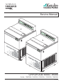
Service Manual
Cr
yo
fug
e6
00
0i
Cr
yo
fug
e8
50
0i
CRYOFUGE 6000i / 8500i
Cat.No.: 75007520 / 75007521 / 75007526 / 75007550 / 75007551
PN 12007520
SERVICE
Table of Contents
Section Title
1
OPERATING INSTRUCTIONS Cryofuge 6000/8500i
2
2.1
2.2
2.3
2.4
2.5
2.6
3
Page
SERVICE
SERVICING SCHEDULE
TROUBLE SHOOTING
TEST POINTS ON MAIN BOARD
ADJUSTMENT OF IMBALANCE SWITCH
CLEANING OF INSTRUMENT PARTS
ELECTRICAL SAFETY CHECK
2-1+2
2-3/7
2-8/10
2-11
2-12
2-12
FUNCTIONAL DESCRIPTION
3.1
3.2
3.3
3.4
3.5
3.6
3.7
BLOCK FUNCTIONS
CONTACTOR PLATE (MAINS INPUT)
MAIN BOARD FUNCTIONS
KEY AND INDICATION BOARD
SPEED DETECTION BOARD
IMBALANCE SWITCH
COOLING PLANT
COOLING PLANT – FLOW CHART
3-1
3-2
3-3+4
3-5
3-5
3-6
3-6
3-7
4
DIAGRAMS
4.1
4.2
4.3
4.4
4.5
4.6
4.7
4.8
4.9
4.10
4.11
4.12
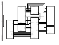
BLOCK DIAGRAM
WIRING DIAGRAMS
WIRING CONNECTION DIAGRAMS
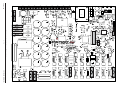
MAIN BOARD - COMPONENT PLAN
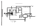
MAIN BOARD - WIRING DIAGRAM
KEY AND DISPLAY BOARD - COMPONENT PLAN
KEY AND DISPLAY BOARD - WIRING DIAGRAM
NOISE FILTER BOARD - COMPONENT PLAN
NOISE FILTER BOARD – WIRING DIAGRAM
INTERFACE BOARD - COMPONENT PLAN AND WIRING DIAGRAM
SPEED DETECTION BOARD - COMPONENT PLAN AND WIRING DIAGRAM
FRONT KEYBOARD - COMPONENT PLAN AND WIRING DIAGRAM
4-1/4-3
4-4/4-7
4-8/4-13
4-14
4-15/4-22
4-23
4-24
4-25
4-26
4-27
4-28
4-29
5
REPLACEMENT OF COMPONENTS
5.1
5.2
5.3
5.4
5.5
5.6
5.7
DISMANTLING THE HOUSING
DISMANTLING OF SEALING ELEMENTS
REPLACEMENT OF MECHANICAL COMPONENTS
REPLACEMENT OF ELECTRICAL COMPONENTS
REPLACEMENT OF DRIVE ELEMENTS
REPLACEMENT OF CONDENSER FAN
REPLACEMENT OF PARTS OF COOLING PLANT - CHARGING INFORMATION
6
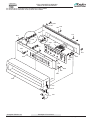
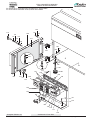
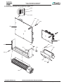
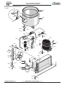
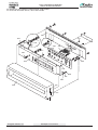
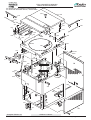
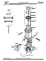
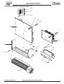
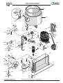
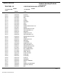
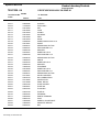
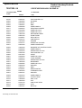
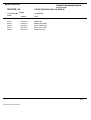
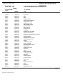
BREAK DOWN DRAWINGS AND LIST OF SPARE PARTS
6.1
6.2
BREAK DOWN DRAWINGS
SPARE PARTS LIST
6-1/14
7
CERTIFICATE
7-1/3
8
TECHNICAL BULLETINS
Edition: 01
26.12.01MH
Contents
Page: 0-1
5-1
5-2
5-3+4
5-5+6
5-7
5-8
5-8+9
Cryofuge 6000i/8500i
SERVICE
Important Note
Technical Information for use of Cryofuges 6000i/8500i
__________________________________________________________________
Cat. No. 75007520 Cryofuge 6000i 3 x 400V 50/60Hz – 4,2kW
Cat. No. 75007521 Cryofuge 6000i 3 x 230V 50Hz – 4,4 kW
Cat. No. 75007526 Cryofuge 6000i Single Phase 230 V 50 Hz – 3,6 kW
Cat. No. 75007550 Cryofuge 8500i 3 x 400V 50/60Hz – 6 kW
Cat. No. 75007551 Cryofuge 8500i 3 x 230V 50Hz – 6 kW
Required door-width :
Dimensions :
Weight :
Ground pressure :
Noise Level:
80 cm
800 mm x 905 mm without wooden palette
Centrifuge 430 kg / Rotor 60 kg
approx. 1450 N/m2
CF 6000i - <64 dB(A); CF 8500i – <67 dB(A)
Voltage :
Required Fuses :
Connection 3 x 400V :
3 x 400V, 50/60 Hz, N capable handling
32 Amp slow blown
Plug Cekon Type CEE 17, 32 A-6 H
3 L + N + PE or directly installed via master power switch
Voltage :
Required Fuses :
Connection 3 x 230V :
3 x 230V/ 50 Hz
32 Amp. slow blown
Plug Cekon Type CEE 17, 32 A-9 H
3 L + PE or directly installed via master power switch
Voltage :
Required Fuses:
Connection 1 x 230V
Single Phase 230 V/50 Hz
32 Amp. slow blown
without plug
Heat rejection to environment :
Edition: 01
26.12.01MH
15.120 kJ/h (14.330,993 BTU) CF 6000i
19.440 kJ/h (18.425,562 BTU) CF 8500i
12.960 kJ/h (12.283,708 BTU) Single Phase
Contents
Page: 0-2
Cryofuge 6000i/8500i
HS/Cf 1e
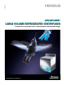
CRYOFUGES ®
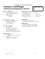
LARGE VOLUME REFRIGERATED CENTRIFUGES
Precision for practical work: in blood banks and biotechnology.
Quality Products. Lifetime Care.
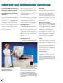
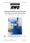
CRYOFUGE 6000i REFRIGERATED CENTRIFUGE
The Cryofuge 6000i is an attractively
designed, large volume floor standing
refrigerated centrifuge by Kendro
Laboratory Products offering
optimised technology for lowspeed
applications.
With a large 6 litre capacity and a top
speed of 4240 rpm (6010 x g), the
Cryofuge 6000i is designed for a wide
range of separation tasks. It can accommodate 1.5 ml tubes, 1 litre containers
and quad blood bags.
It is ideal for use in blood banks, biotechnology and the pharmaceutical industry,
where large volumes are centrifuged at
high speeds and constant temperatures.
It is also used for routine separation tasks
in laboratories and production facilities.
The Cryofuge 6000i is competitively
priced and comes with a wind-shielded
rotor and an extensive range of accessories. Back up from an international
support and service organisation ensures
maximum performance and reliability.
The use of sophisticated microelectronics
systems and high strength materials for
rotors and accessories guarantees outstanding reproducibility and highly
accurate centrifugation.
Typical applications
The Cryofuge is designed, in particular,
for the qualified production of human
blood components in blood banks. It is
also used for blood fractionation, serum
extraction, radio immuno assays (RIA),
cell preparation, fractionating protein and
enzyme precipitates, separating fine crystal
deposits – and in fact, in every situation
where high performance and capacity are
required.
Powerful technology
The Cryofuge is equipped with a powerful, maintenance free induction drive for
User friendly
A new automatic lid lock enables the
Cryofuge to be closed easily. The ergonomically designed keypad allows simple
entry and storage of operating parameters. Main control functions are
conveniently arranged for easy access,
while the SEPACONTROL® control system
makes operation straightforward. The
"delay" function permits users to delay
system start-up.
Microprocessor control
The Cryofuge is equipped with 33 centrifugation programs for routine applications.
Nine acceleration and nine braking profiles
ensure reproducibility of all centrifugation
parameters. The Cryofuge is now also
equipped with a profile program for
defining up to 10 cut-off points with time,
speed, braking and acceleration curves.
Speed is controlled digitally with automatic RCF adjustment. Centrifuges can
also be connected to a computer for
data recording via a serial interface.
Safety
When designing the Cryofuge, all international safety standards were kept in
mind to guarantee the highest level of
safety. Diagnostic and fault messages are
clearly visible. Pre-selection of buckets
protects against overspeeding. The lid
lock system and steel armoured rotor
chamber further ensure safe operation.
A key operated switch safeguards
against unauthorised use.
Service friendly
The Cryofuge is equipped with a digital
self diagnosis system for monitoring
operability. If a fault is detected, a message is immediately displayed. Should
an error occur, however, our fast and
efficient international service team can be
relied upon.
The Cryofuge 6000i Refrigerated
Centrifuge is used for the qualified
production of human blood
components in blood banking.
quiet and smooth operation. Its refrigeration system uses the environmentally
friendly CFC free refrigerant R 404a.
Acceleration and braking times have
been optimised for all application requirements. An automatic digital temperature
compensation system prevents samples
from freezing.
02
Conveniently arranged function
keys and easy to read digital
display for simple operation and
quick access.
Ergonomically designed keypad
allows simple reproduction of
operating parameters.
Keys for controlling basic
functions are also located on
the front of the Cryofuge for
immediate access.
03
Convenient operation
The SEPACONTROL operating panel is
systematically arranged, clearly displays
all functional areas and permits easy
access to operating parameters. The
user simply presses a few keys to select
the required centrifugation program and
start the Cryofuge. A design which
eliminates knobs and dials ensures high
reproducibility and easy cleaning of the
control panel.
SEPACONTROL provides users with
up-to-date information on the status of
the system. Visual diagnostic indicators
and acoustic signals supplement the
information supplied by the microcomputer. This makes it easy to use the
centrifuge right from the start.
Key operated switch
This switch protects programs against
unauthorised access. Depending on the
position of the switch, users are either
permitted to freely program the system,
call up one of the 33 programs in
memory or simply repeat the program
last used.
Panel
Five visual displays facilitate the identification of problems during centrifugation.
When the lid is opened (check lid), the
rotor is unevenly balanced (imbalance),
in the event of a system error (system
check), programming error (progr. error)
or if the temperature limit has been
exceeded (overtemp), an LED signals a
warning.
Memory control
33 memory locations are available to
save run parameters for future use. New
programs generated using the function
panel can be immediately added to the
library.
Status
The status field is systematically arranged
into the following areas: start-up and
braking curves, speed and rotor data,
time and temperature. LEDs prevent the
user from confusing the values on the
display.
Programming
The programming field permits easy
setting of the required parameters. Only
5 keys are required for completely programming all parameters! The keys are
used for changing the display setting,
values displayed and confirming input.
04
Wind-shielded rotor and lid, showing a selection of the extensive range of buckets and
adaptors.
Simple, functional operation
The basic functions for opening the
centrifuge lid, starting and stopping the
system and quick-stop are located on
the front of the Cryofuge for immediate
access.
CRYOFUGE
6000i GMP
AND 8500i GMP
Rotor and accessories
An aerodynamic wind-shielded rotor and
6 different types of bucket ensure maximum performance and flexibility. The windshielded rotor is included in the basic
centrifuge package. The vast range of
accessories is listed in the tables overleaf.
The Cryofuge 6000i GMP (Good Manufacturing Practice) offers the same performance and accessories as the Cryofuge
6000i. The Cryofuge 8500i GMP attains a
maximum centrifugal force of 8525 x g
and a maximum speed of 5050 rpm.
GMP Cryofuges are specially designed for
use in clean room applications.
Four buckets have been specially developed for centrifuging blood and producing thrombocyte concentrates. The
system can handle all standard blood
pack systems. Additional accessories
such as plastic inserts and balancing
accessories round off the package.
Two other buckets used in combination
with various adaptors permit all tubes
with nominal volumes between 1.5 ml
and 1000 ml to be centrifuged.
HERANET data documentation
The Heraeus HERANET data documentation system is available for data
documentation in accordance with GMP.
Please request our HERANET brochure
from your Kendro representative.
Special features of the Cryofuge
6000i GMP and 8500i GMP
The special encapsulated casing is sealed
to prevent particles from escaping and
contaminating the clean room. The space
between the centrifuge and floor is equipped with a rubber gasket. Thanks to its
special smooth finish, the casing is very
easy to clean. The 6000i GMP and 8500i
GMP are equipped with connections for
an external cooling water system; the flow
rate of the cooling water is kept to a minimum. On request, the system can be
connected to an external cooling system.
The enclosed and sealed casing and
vibration insulation system ensure low
noise generation during operation. Heat
radiation is also minimised.
Before installing the Cryofuge GMP, please
be sure to contact the Kendro Service
Department.
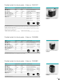
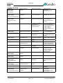
Double bucket for blood packs – Order no. 75007617
Model
Cryofuge 6000i
Cryofuge 8500i
Technical data
Max speed (rpm)
4,000
4,000
Operation with blood packs double-quint
Max. RCF (x g)
5,312
5,312
No. of pack systems/bucket
Max. capacity
2 x 800 ml
2 x 800 ml
Polyamide plastic inserts:
Max. perm. mass (g)
3,500
3,500
Order no. M 2)
Min. temp. at max. RCF*
–5 °C
–5 °C
Opening M (mm)
Max. acceleration time (s)
140
140
Order no. L1)
Min. braking time (s)
180
180
Opening L (mm)
Radius (cm)
29.9
29.9
Order no. XL3)
Opening XL (mm)
Order no. XXL4)
Opening XXL (mm)
2
76007667
110 x 57
76007647
110 x 70
76007657
110 x 76
76007677
Double bucket for blood packs
75007617
110 x 88
* At ambient temp. of 25 °C
M, L and XL plastic inserts come complete with balancing weights 75007645. One set of balancing weights includes
4 weights of 6 and 15 g each. Balancing plates 75005759 can be used to compensate big weight differences. One set
includes 2 plates at 35 and 65 g each.
The balancing insert 75007668 consists of an XL plastic insert, 2 balancing weights and 30 balancing plates, enabling
compensation of up to a full bucket load.
1)
2)
Suitable for triple and quad systems.
Suitable for double systems.
3)
Suitable for quad systems, systems with soft filters. 4) Suitable for quad and quintuple systems, systems with filters.
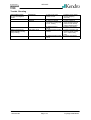
Double bucket for blood packs – Order no. 75006694
Model
Cryofuge 6000i
Cryofuge 8500i
Technical data
Max speed (rpm)
4,240
5,050
Operation with blood packs double-trip.
Max. RCF (x g)
5,768
8,182
No. of pack systems/bucket
Max. capacity
2 x 750 ml
2 x 750 ml
Opening measurements (mm)
Max. perm. mass (g)
3,700
3,700
Plastic insert order no.
Min. temp. at max. RCF*
–4 °C
+6 °C
Plastic insert opening (mm)
Max. acceleration time (s)
150
190
Plastic insert material
Min. braking time (s)
190
220
Radius (cm)
28.7
28.7
2
99 x 70
75006695
95 x 60
PE
Double bucket for blood packs
75006694
* At ambient temp. of 25 °C
Bucket for blood packs 75006695 comes with plastic insert 75006694.
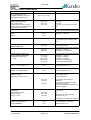
Double bucket for blood packs – Order no. 75006801
Model
Cryofuge 6000i
Cryofuge 8500i
Technical data
Max. speed (rpm)
4,000
4,000
Operation with blood packs double-trip.
Max. RCF (x g)
5,170
5,170
No. of pack systems/bucket
Max. capacity
2 x 750 ml
2 x 750 ml
Opening measurements (mm)
Max. perm. mass (g)
3,100
3,100
Plastic insert order no.
Min. temp. at max. RCF*
–5 °C
–5 °C
Plastic insert opening (mm)
Max. acceleration time (s)
140
140
Plastic insert material
Min. braking time (s)
180
180
Radius (cm)
28.9
28.9
2
99 x 139
75006609
99 x 57
PP
Double bucket for blood packs
75006801
* At ambient temp. of 25 °C
05
Double bucket for blood packs – Order no. 75006680
Model
Cryofuge 6000i
Cryofuge 8500i
Max. speed (rpm)
4,000
4,000
Technical data
Operation with blood packs double-trip.
Max. RCF (x g)
5,310
5,310
No. of pack systems/bucket
Max. capacity
2 x 700 ml
2 x 700 ml
Opening measurements (mm)
Max. perm. mass (g)
3,100
3,100
Accessories:
Min. temp. at max. RCF*
–5 °C
–5 °C
Metal handles
Max. acceleration time (s)
140
140
Rubber spacer for shorter
2
95 x 55
75006728
Min. braking time (s)
180
180
packs fitted with
Radius (cm)
29.7
29.7
handle 75006728
76014725
Double bucket for blood packs
75006680
* At ambient temp. of 25 °C
Additional accessories for blood pack operation
Order no. 75006683
Pack of "shoe horns" for inserting blood packs,
Order no. 75006684
Set of non stick plastic bags (150 each) for smooth insertion and removal of
incl. 1 set of rubber rings
blood packs
Double rectangular bucket
76008078
Order no. 75006681
12 rubber volume compensation plates
Order no. 75005759
4 rubber balancing plates
Double rectangular bucket – Order no. 76008078/75015501
Double rectangular bucket
76008078 with adaptors for standard tubes
Model
Cryofuge 6000i
Max. speed (rpm)
4240/3006
Cryofuge 8500i
5050/3006
Max. RCF (x g)
4984/2506
7070/2506
Max. capacity
24 x 15 ml/3 racks1)
24 x 15 ml/3 racks1)
Max. perm. mass (g)
2500/1800
2500/1800
Min. temp. at max. RCF*
–4 °C
+6 °C
Max. acceleration time (s)
150
190
Min. braking time (s)
190
220
Radius (cm)
24.8
24.8
* At ambient temp. of 25 °C
1)
Boehringer Mannheim or Hitachi-5 sample racks
Accessories for standard tubes in double bucket 76008078
Nominal volume of tube (ml)
1.5
7
7
15
15
15
25
25
50
50
50
50
50
100
150
No. of tubes per adaptor
40
20
12
12
11
61)
5
4
2
2
6
2
1
1
1
No. of tubes per rotor
480
240
144
144
132
72
60
48
24
24
36
24
12
12
12
Type of tube
ML
DIN
B. Coll.
DIN
B. Coll. Falc.
DIN
Univ.
DIN
Falc.
Falc.
Univ.
Oil
DIN
DIN
Max. length of tube (mm)
45
110
110
111
109
121
100
120
130
120
117
120
S
120
120
Max. tube ø (mm)
11
13
14
17
17
17
25
25.5
35
29.5
29
29.5
S
45
55
Max. cap ø (mm)
–
14
18
18
19.5
23
25.9
31
36
37.5
35
37.5
S
48
–
Colour of adaptor
black
yellow
grey
red
white
brown
orange
green
green
gr./yel.
nat.
gr./yel.
nat.
blue
black
Adaptor order no. (7500xxxx)
5335
Stand. tube order no. (7500xxxx) 1163a)
C
5321
5330
5322
5327
5387
5323
5391
5324
5386
2261
5389
5339
5325
5326
9001b)
–
9003b)
–
2845c)
9006b)
–
9005b)
2844e)
2844e)
–
3113d)
9007b)
1132b)
S
R
R
F/R
F/R
F/R
F/R
C
F/R
F/R
F/R
F/C
C
F
Make sure that the bucket swings out correctly when all places are used.
Type of tube: ML = microlitre tube; B. Coll. = blood collection tube ("Vacutainer", "Monovette", etc.); Falc. = "Falcon®" (conical tube); Oil test = oil test tube, pear shaped;
Univ. = universal container (with vertical edge, Falcon type).
Standard tube: a) 1.5 ml microlitre tubes, b) borosilicate glass, c) 12 ml Nunc. screw cap tube, d) oil test tube, pear shaped, e) 50 ml Falcon screw cap tube.
Adaptors can be used with tubes with the following shape bottom: F = flat, R = round, C = conical, S = special
1)
06
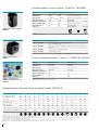
Round bucket – Order no. 75008165
Model
Cryofuge 6000i
Cryofuge 8500i
Max. speed (rpm)
4,240
5,050
Max. RCF (x g)
6,010
8,525
Max. capacity
1 x 1000 ml
1 x 1000 ml
Max. perm. mass (g)
3,200
3,200
Min. temp. at max. RCF*
–4 °C
+8 °C
Max. acceleration time (s)
150
190
Min. braking time (s)
190
220
Radius (cm)
29.9
29.9
Round bucket 75008165
* At ambient temp. of 25 °C
Aerosol tight cap (order no. 75008081) available on request.
Accessories for large volume tubes in
round bucket 75008165
Nominal volume of tube (ml)
250
2502)
250
500
650
750
1000
1000
Bp.
DACS
No. of tubes per adaptor
1
1
1
1
1
–
1
–
1
1
6
6
6
No. of tubes per rotor
6
6
6
6
6
6
6
Type of tube
DIN
Div./H. Corni. H
DIN
H
H
HST
Sing.-trip. DACS
Max. length of tube (mm)
190
190
190
190
1953)
148
190
175
–
Max. tube ø (mm)
59
62.5
61.5
70
84
100
100
99.5
–
–
Max. cap ø (mm)
–
–
–
–
–
87
87
–
–
–
Colour of adaptor
nat.
nat.
nat.
nat.
nat.
-
-
-
nat.
black
Adaptor order no. (7500xxxx)
66494) 8144
8147
8145
66376) –
–
–
6639
5254
–
7718
11587) 8149
6613
6640
–
–
Stand. tube order no. (7500xxxx) 1135b) 7894
F3)
FR
C
F
F
R
F
–
S
S
Adaptor for large volume tubes
for round bucket 75008165
S
Nominal volume of tube: Bp. = blood pack, DACS = Density Associated Cell Sorting (DACS™ 300, Fresenius)
Type of tube: Div. = diverse, Corni. = Corning bottle, H = Heraeus tube, HST = Heraeus stainless steel tube
Standard tube: b) borosilicate glass.
2)
Additional pad for conical tubes required from manufacturer, 3) Only use without cap 75008081,
4)
Pad 75001808 required, 6) Pad 75001913 required, 7) max. speed – 2,600 rpm
Adaptors can be used with tubes with the following shape bottom: F = flat, R = round, C = conical, S = special
Round bucket 75008165 with
adaptors for standard tubes
Accessories for standard tubes in round bucket 75008165
Nominal volume of tube (ml)
1.5/2
7
7
15
15
15
25
50
50
100
No. of tubes per adaptor
48
35
19
19
17
12
7
4
4
2
No. of tubes per rotor
288
210
114
114
102
72
42
24
24
12
Type of tube
ML
DIN
B. Coll.
DIN
B. Coll.
Falc.
DIN
DIN
Falc.
DIN
Max. length of tube (mm)
42
177
177
177
177
177
177
177
177
177
Max. tube ø (mm)
11
13
14
17
17
17
25
35
29.5
45
Max. cap ø (mm)
–
14
18.5
18.5
20
23.7
31
39
39
47.5
Colour of adaptor
black
yellow
grey
red
white
brown
orange
green
gr./br.
blue
Adaptor order no. (7500xxxx)
8132
8133
8134
8135
8136
8137
8138
8140
8141
8142
Stand. tube order no. (7500xxxx)
1163a)
9001b)
–
9003b)
–
2845c)
9006b)
9005b)
2844e)
9007b)
F/C
F/R
F/R
F/R
F/R
F/C
F/R
F/R
F/C
R
Type of tube: ML = microlitre tube; B. Coll. = blood collection tube ("Vacutainer", "Monovette", etc.); Falc. = "Falcon" (conical tube).
Standard tube: a) microlitre tubes, b) borosilicate glass, c) 15 ml Falcon screw cap tube, e) 50 ml Falcon screw cap tube.
Adaptors can be used with tubes with the following shape bottom: F = flat, R = round, C = conical.
07
TECHNICAL DATA
Model
Cryofuge 6000i
Cryofuge 8500i
Description
Large volume refrigerated
Large volume refrigerated
floor standing centrifuge
floor standing centrifuge
Max. speed
4240 rpm
5050 rpm
Max. RCF
6010 x g
8525 x g
Max. capacity
6 x 1000 ml bottles or 12 blood pack 6 x 1000 ml bottles or 12 blood
systems of 800 ml each
pack systems of 800 ml each
High performance induction drive,
High performance induction drive,
SEPACONTROL with
SEPACONTROL with
microprocessor
microprocessor
braking profiles
9/10 profiles
9/10 profiles
Runtime
1 min – 99 hrs, continuous operation 1 min – 99 hrs, continuous operation
Program memory
33 user centrifugation programs, one of which with freely combinable
Control and drive
The Cryofuges 6000i and 8500i
are now even more convenient
to operate with a load-relief lid
for easy opening and closing.
Acceleration and
braking and acceleration curves, key operated switch for protection
against unauthorised access, data last used saved, in the case of a
power interruption data saved for unlimited period of time.
Temperature control range
–20 °C to +40 °C
Safety features
Lid lock and interlock, imbalance cut-out, steel armoured chamber
–20 °C to +40 °C
Design
Sturdy, torsion resistant steel design with stainless steel rotor chamber
Dimensions (hxwxd)
1178 x 800 x 905 mm
1178 x 800 x 905 mm
Weight (excl. rotor)
445 kg
445 kg
Power consumption
4.2 kW
5.4 kW
Refrigeration unit
1.9 kW
1.9 kW
Recommended fuse
25A
25A
Designed and tested
IEC 1010, UVV VBG 20, UVV VBG 7z, UVV VBG 4, DIN 58970 part 1,2,
in acc. with
4, radio interference suppression in compliance with VDE 0871 B
Rotor
Wind-shielded rotor
75006606
75006606
included in basic package
included in basic package
ORDER NUMBERS
Order number
Cryofuge 6000i
220 V/3 Ph/50 Hz
75007521
230 V/1 Ph/50 Hz
75007526
400 V/3 Ph/50 Hz
75007520
Cryofuge 8500i
GMP model
400 V/3 Ph/50 Hz with built-in refrigeration unit
with external refrigeration unit
Australia
Austria
Canada
Denmark
France
Germany
India
Italy
Poland
Portugal
PR China
Spain
Sweden
Switzerland
U.K./Ireland
USA
75007562
75007561
75007566
Kendro Laboratory Products · Lane Cove DC · NSW 2066 · Tel. +61 (02) 9936 1540 · Fax. +61 (02) 9427 9765 · [email protected]
Kendro Laboratory Products GmbH · Wien · Tel. +43 (1) 801 40-0 · Fax +43 (1) 801 40 40 · [email protected]
Kendro Laboratory Products International Sales · Newtown · USA · Tel. +1 (203) 270-2080 · Fax. +1 (203) 270-2166 · [email protected]
Kendro Laboratory Products AB · Albertslund · Tel. +45-43 62 46 47 · Fax +45-43 62 46 41 · [email protected]
Kendro Laboratory Products · Courtaboeuf cedex · Tel. +33 (1) 69 18 77 77 · Fax +33 (1) 60 92 00 34 · [email protected]
Kendro Laboratory Products GmbH · Hanau · Tel +49 (6181) 35-300 · Fax: +49 (6181) 35-59 44 · [email protected]
Kendro Laboratory Products (India) Pvt. Ltd. · New Delhi · Tel. +91 (11) 618 58 40 · Fax +91 (11) 618 53 97 · [email protected]
AHSI S.p.A. · Cavenago Brianza · Tel. +39 (02) 95 08 11 · Fax +39 (02) 95 08 12 77 · [email protected]
Kendro Spólka z.o.o. · Warszawa · Tel. +48 (22) 663 43 23 · Fax +48 (22) 663 43 25 · [email protected]
Heraeus S.A. · Cacem · Tel. +351 (1) 912 08 65 · Fax +351 (1) 912 08 60 · [email protected]
Kendro Laboratory Products (H.K.) Ltd. · Hong Kong SAR · Tel. +852 2711-3910 · Fax +852 2711-3858 · [email protected]
Heraeus S.A. · Madrid · Tel. +34 (91) 358 19 96 · Fax +34 (91) 358 20 67 · [email protected]
Kendro Laboratory Products AB · Upplands Väsby · Tel. +46 (8) 59 07 21 90 · Fax +46 (8) 59 03 16 00 · [email protected]
Kendro Laboratory Products AG · Zürich · Tel. +41 (1) 454 12 12 · Fax +41 (1) 454 12 99 · [email protected]
Kendro Laboratory Products SA · Carouge-Genève · Tel. +41 (22) 343 21 67 · Fax +41 (22) 342 38 31 · [email protected]
Kendro Laboratory Products Limited · Bishop’s Stortford · Herts · Tel. +44 (1279) 827700 · Fax +44 (1279) 827750 · [email protected]
Kendro Laboratory Products L.P. · Newtown · Tel. +1 (800) 522-7746 · Fax. +1 (203) 270-2166 · [email protected]
All other International Sales in Europe, Middle East, Africa
Kendro Laboratory Products International Sales · Hanau · Germany · Tel. +49 (6181) 35-300 · Fax +49 (6181) 35 59 44 · [email protected]
Asia Pacific Kendro Laboratory Products (H.K.) Ltd. · Hong Kong SAR · Tel. +852 2711-3910 · Fax +852 2711-3858 · [email protected]
Latin America Kendro Laboratory Products International Sales · Newtown · USA · Tel. +1 (203) 270-2080 · Fax. +1 (203) 270-2210 · [email protected]
Internet
http://www.kendro.com . http://www.heraeus-instruments.com
Kendro Laboratory Products – a worldwide company formed by the merger of Heraeus Instruments and Sorvall.
Should your country not be included in the address list, please contact Kendro Laboratory Products International Sales in Germany or USA.
Subject to change without notice.
Printed in Germany 6C 07/99 VN 4t Frotscher
SERVICE
2.
SERVICE
2.1
Servicing Schedule (Yearly Procedure)
2.1.1
Maintenance Routine without Dismantling the Centrifuge
1. Electrical Installation and Safety
Switch OFF the centrifuge and disconnect the unit from power.
Check voltage supply and mains fusing (3 x 32 Amps slow blow characteristic or other for
corresponding line voltages)
Check condition of plug and wall socket - replace defective parts.
Check main contactor for burnt out poles.
Check cord condition and fixing - replace or refit it.
2. Location and Mechanical Installation
Check the base for resonance-free and stable conditions.
Check for a well ventilated place and sufficient distances to walls or adjacent equipment (min.
30 cm), avoid direct sunlight.
Check the levelling of the centrifuge - use a spirit level.
3. Lid Locking Mechanism and Safety Device
Connect the centrifuge to power and switch ON
Check for easy lid closing and self-acting lid opening - if in disorder, re-adjust lid looped hooks
and/or hinges and/or move lid lock assembly aside and smear hooks slightly with grease.
Check the central rubber gasket for lid sealing and replace it, if damaged.
Open the lid and turn the rotor by hand, then close the lid and try to open it using the lid key: the
lid must not be opened as long as the speed values (> 10 rpm) are indicated - if safety circuit is
out of function, replace main board.
4. Cleanliness of Spin Chamber and Motor Cover
Open the lid and remove the rotor: for loosening turn rotor's collar nut with use of 19 mm fixed
spanner anti clock wise (in arrow direction - see rim of rotor bowl), thereby hold the rotor on it's
cross.
There is an additionally turn resistance after approx. one revolution which has to be overcome
with an further lever pressure of the fixed spanner. Then turn the drive shaft clockwise with the
10 mm socket wrench as long as the rotor can be lifted up. Two persons are necessary to seize
the rotor by it arms on opposite and to lift the rotor carefully out of the bowl.
Clean the wind-shield with a dry and absorbent cloth (remove all dust and moisture - see also
2.5 Cleaning)
Check the correct seat and condition of the motor cover.
Take care of the cleanliness of the annular slot around the motor shaft: there is shaft packing of
felt which has to be soaked with oil. - Penetrating fluids can damage the upper motor bearing.
5. Rotor and Bucket Condition and Sealing
Check the condition of rotor and buckets (especially all supporting or stressed partitions as jib
arms, rim of the bucket's bearing surface etc.): the rotor and/or buckets must not be used any
longer, if there are visible traces of mechanical damage or rust.
Check the condition of rotor and/or bucket sealing and replace them in case of malfunction
6. Rotor Fixing and Motor Shaft
Check the condition of the drive motor shaft: the centrifuge must not be used any longer, if the
drive shaft is damaged (bend, thread is worn out, horizontal grooves etc.)
7. Temperature Control Circuit
Clean the condenser (use a vacuum cleaner).
Check the thermal isolated fixing of the temperature sensor.
Re-install the rotor and run the centrifuge at 2000 rpm (1500 rpm with buckets #7719) and at
4°C
Check the temperature 30 minutes later: the displayed and measured value should be
approximately the same (tolerances +/-2K)
Edition: 02
18.04.02 MH
Service
Page: 2-1
Cryofuge 6000i/8500i
SERVICE
2.3.2 Maintenance Routine after Dismantling the Centrifuge Casing (see Section 5)
1. Motor Supporting Elements
Check the supporting and damping motor elements (enlarged rubber abrasion, often imbalance
runs) and replace them by worse condition or at least every 3 years.
2. Imbalance Switch
Check the function of the imbalance switch and replace in case of malfunction.
3. Braking Circuit
Check the function of the braking circuit (warming up of brake resistor, even and noiseless
brake effect) and replace defective parts in case of malfunction.
4. Lead and Screwing Connections
Check the terminal and plug connections of leads on all boards and electrical components,
replace defective parts.
Check the screwing connections of boards, mechanical and electrical components and tighten
them if necessary.
5. Protection Earth Core and Grounding Connections
Check the protection earth core for continuity and all grounding plug connectors (see also 2.6
Electrical Safety Check).
Check insulation resistance and measure the substitutional leakage current (see 2.6)
Edition: 02
18.04.02 MH
Service
Page: 2-2
Cryofuge 6000i/8500i
SERVICE
Trouble Shooting
Error Indication
"check lid" LED on,
interval sound
Error Cause
Possible
Error Source
Corrective Procedure
lid opened
mechanically
during run
FORBIDDEN!
mechanical
emergency lid
opening must only be used
at standstill
close lid immediately,
turn power OFF/ON,
press start to continue run,
press stop to finish run
circuit for lid switches
interrupted
during run
lid switches or leads are
interrupted
check leads to the lid
switches, if micro switch is
faulty, change lid lock
assembly
1) check leads to lid
switches, if micro switch
is faulty - replace lid lock
assembly
1) open lid, check load,
close lid again and start
2) change or reinforce the
base
"check lid" LED on and
"OPEn"
15 V circuit for lid switches
is interrupted
at standstill
"imbalance"
LED on, interval sound
imbalance circuit has
released
1) leads to lid switches
interrupted or defective
lid switch
1) rotor not symmetrically
loaded
2) base is not sturdy
enough and comes into
vibrations
3) centrifuge is not
correctly levelled
4) disjusted or faulty
imbalance switch
5) leads to imbalance
switch are interrupted
"overtemp"
LED on, interval sound
6) faulty component of
imbalance circuit
just after starting: drive is ∆t alarm
switched off
during longer operation:
rotor coasts to standstill
without braking
1) ∆t is programmed
2) without programming
of ∆t
E-00 appears
system check
LED on and interval sound
rotor didn't turn
1) rotor is jammed
2) motor is jammed
faulty speed signal
easy check:
turn rotor by hand and
close lid speed values must be
indicated
motor didn't start
1) faulty plug or lead
connections or faulty
speed detection board
2) faulty processing
circuit on main board
1) connection: drive to
main board
2) defective drive
3) faulty main board
Edition: 02
18.04.02 MH
Service
Page: 2-3
3) level the centrifuge drive
correctly, use a spirit level
on top of installed rotor
4) readjust imbalance
switch or replace in
case of malfunction
5) check leads with
ohmmeter and replace if
faulty
6) replace main board
Rotor chamber must be
precooled before ∆t
activation
1) check minimum
reachable temperatures
at maximum speed and
20°C, check cooling
plant in case of big
deviation
2) check compressor and
cooling plant (loss of
refrigerant)
1) check for easy
movement, remove any
jamming objects
2) remove drive, replace
faulty parts
1) check plug contacts
and leads - measure
speed detection signal
on XW1, XW3 - replace
faulty parts
2) replace main board
1) check terminal and
lead connections,
replace faulty parts
2) check resistance of
motor windings, replace
faulty parts
3) replace main board
Cryofuge 6000i/8500i
SERVICE
Trouble Shooting
E-02 flashes
system check
LED on and
interval sound
program sequence
disturbed
bad ground connection
check all ground
connections,
tighten loose screws
E-03 flashes
system check
LED on and interval sound
faulty speed signal
during run
see E-00
or e.g. missing rotor
wait until rotor has come to
standstill, then see E-00
E-04 flashes
system check
LED on and interval
sound
faulty temperature
measuring
E-06 flashes
system check
LED on and interval sound
data lines to keyboard
disturbed during operation
1) faulty temperature
sensor (PT100) or leads
1) check plug connection
and resistance of
PT 100, replace faulty
sensor
2) defective amplifier or
converter test:
substitute PT100 by
100Ω and 120Ω
2) set the temperature to
20 °C and watch the
display: after power ON
100Ω ->(0±2)°C
120Ω ->(50±2)°C
replace defective main
board
1) replace plug contacts
or connecting leads
1) faulty plug contact or
connecting leads
2) faulty tracks or
components
E-08 flashes
System check
LED on and interval sound
over voltage in DC
intermediate circuit
1) leads to brake resistor
interrupted or defective
resistor
2) faulty intermediate
circuit
1) defective motor
over current in DC
intermediate circuit
over temperature of the
electronics
E-10 appears
system check
LED on and interval sound
E-12 flashes
system check
LED on and interval sound
E-15 appears
system check
LED on and interval
sound
E-17 appears
system check
LED on and interval sound
2) faulty frequency
converter
insufficient cooling of
power electronics
Edition: 02
18.04.02 MH
1) disconnect the motor,
check motor windings,
replace defective motor
2) replace main board
program sequence
disturbed
NV-RAM not initialised
check wall distance, air
ventilation and fan
function, change bad
conditions, replace
defective parts
insert the correct NV-RAM
temperature signal
disturbed
see E-04
see E-04
program sequence
disturbed
reading error of NV- RAM
(checksum)
if error indication occurs
repeatedly replace NVRAM
micro switch didn't open
after pressing lid key
1) faulty leads or micro
switch
2) defective lid lock
E-22 appears
system check
LED on and interval sound
2) change key and
indication board or main
board
1) check leads and brake
resistor, replace defective
parts
2) replace main board
NV-RAM and micro
controller can not
cooperate
micro controller or NVRAM are mixed up
Service
Page: 2-4
1) replace defective parts
2) replace lid lock
assembly
check the correct
identification
No's of micro controller
and NV-RAM
Cryofuge 6000i/8500i
SERVICE
Trouble Shooting
E-23 appears system
check
LED on and interval sound
mains contactor didn't
pull up, hour counter
doesn't run
mains contactor has been
cut off, rotor coasts to
standstill without braking
1) interruption of the
mains security path
2) defective driving of
mains contactor
main security path is
interrupted by one of the
safety elements:
1) F3: compressor’s over
current protection
2) F4: motor over
temperature switch
3) F5: over pressure
switch of cooling plant
mains contactor has
pulled, hour counter runs,
rotor doesn't start or
coasts to standstill without
braking
1) missing mains phase
for supply of frequency
converter or defective 35
slow blown fuse
2) faulty driving of
preloading for
intermediate circuit
displays remain dark
no mains voltage supply
1) Phase L2 or fuse F2
failed
2) defective mains cord
or mains switch
no low voltage supply for
key and display board
all displays elements are
shortly illuminated
interrupted program
sequence
processor reset
caused by
electromagnetic
disturbance
1) faulty connection from
main board to key board
2) faulty keyboard
3) faulty main board
NV-RAM out of socket or
not correctly inserted
1) reduced voltage
supply (< 10%)
2) bad or missing
ground connection
Edition: 02
18.04.02 MH
Service
Page: 2-5
1) check F3,F4,F5 and
closing contacts of K2
inclusive all connecting
lines and replace
defective parts
2) replace contactor or
main board
1) F3: check main
phases, measure the
compressor current and
compare with adjustion
of protection switch,
check compressor
windings, replace
defective compressor
2) F4: check air
ventilation and motor
windings, replace
defective parts
3) enlarge the lateral wall
distance, clean condenser, replace defective
fan or make clogged
injection valve free
1) check mains phase or
replace defective fuse, if
it blows again check for
other faults (drive
resistance's,
intermediate circuit),
replace defective parts
2) check the switching
action of relay K1 and
replace main board in
case of malfunction
1) check phase and fuse
or circuit breaker and if
faulty, replace or switch
on again
2) check leads and
switch, replace defective
parts
1) check plug
connections on main
and key board, check
connecting leads replace faulty parts
2) replace keyboard
3) replace main board
insert the right NV-RAM
correctly
1) if the voltage supply
drops often, use a
voltage stabiliser
2) check all ground
connections and
screwings of main board
Cryofuge 6000i/8500i
SERVICE
Trouble Shooting
drive makes noises no good centrifugation
results
drive accelerates but
doesn't brake normally (noisy braking)
mechanical
1) wear out of motor
rubber mounts
electrical
2) motor bearing
1) defective terminal
connection or faulty lead
or mot. winding
faulty brake circuit
2) defective driving
circuit
1) defective lead or brake
resistor
2) defective brake control
circuit
Edition: 02
18.04.02 MH
Service
Page: 2-6
1) replace motor rubber
mounts (damping
elements)
2) replace motor
1) check voltage on
motor terminal (see test
points on main board),
replace defective parts
2) replace main board
1) check connection and
leads and brake resistor
25 Ω , replace faulty
parts
2) change main board
Cryofuge 6000i/8500i
SERVICE
2.3 Test Points on Main Board
Test Points
1) mains terminal XT
(L2 for low voltage supply)
nd
2) mains terminal L1 to N (or 2
phase)(intermediate circuit)
terminal XM 1 to XM 3
motor voltage measured
inter 2 motor leads voltage values must be the same
between all 3 motor leads after the
selected speed is reached
motor current
Unit Value
230 V AC
230 V AC (-/+10%)
260 V AC
255 V AC
245 V AC
cable 1
cable 2
cable 3
8.0 A
8.0 A
8.0 A
max. acceleration current
15 A
intermediate circuit voltage UD
bridge rectifier V49
current of intermediate circuit
through control resistor R29
measured as voltage drop:
U=IxR
Condition
all given values refer to 230V
rotor 75006606 with buckets 75008078
1 000 rpm
2 500 rpm
4 240 rpm, acc. time: 95s, dec. time:
180s
soft iron or moving-iron or digital
effective current measuring instrument
rotor 75006606 with buckets 75008078
set speed = 4 240 rpm
rotor 75006606 with buckets 75008078
(in the speed range of 2000 to 3000
rpm)
320 V DC
355 V DC
at standstill
during braking phase
300 V DC
280 V DC
rotor 75006606 with buckets 75008078
set speed = 4 240 rpm
shortly by max. acceleration
8.5 mV DC
31 mV DC
103 mV DC
250 mV DC
-12 mV DC
rotor 75006606 with buckets 75008078
set speed = 1 000 rpm
set speed = 2 500 rpm
set speed = 4 240 rpm
shortly by max. acceleration
shortly during braking phase
motor winding resistance
inter 1 -> 2, 2 -> 3 and 1 -> 3
0.5 Ω
motor temperature: 20 °C
plug XD
resistance of brake resistor
25 Ω
resistor temperature: 20 °C
plug XE
imbalance switch
voltage drop inter pin 1 and 4
installation:
mechanically closed,
electrically opened
6.5 V DC
12 V DC
0 V DC
plug XW
voltage drop
speed detection board
inter pin 1 and 3:
inter pin 1 and 2:
12.0 V DC
10.7 V DC
0.3 V DC
plug inserted, open switch (no
imbalance)
plug removed, or leads interrupted
(imbalance message)
switch closed (plug re-inserted, active
imbalance signal)
active circuit
UB
transistor is cut in (slot position)
transistor is cut out
speed signal: two pulses per revolution
terminal XC
resistance of lid solenoid
terminal XC1/XC2
Edition: 02
18.04.02 MH
120 Ω
8Ω
Service
Page: 2-7
2 x 240Ω parallel – old version
latch motor pin 3 to 4
Cryofuge 6000i/8500i
SERVICE
Test Points on Main Board
plug XA
micro switches for lid locking
30 V DC
by open lid
terminal XB
motor over temp. switch
230 V AC
contact open
230 V AC
contact open
230 V AC
contact open
95 mV DC
20 °C temperature indication
terminal XN
compressor thermal over current
switch
terminal XO
pressostat
plug XU
voltage drop on PT100
compressor terminal box
1) voltage
2) current
3) resistance of compressor
winding
between C + R (C + P)
between C + S (C + A)
between R + S (A + P)
Edition: 02
18.04.02 MH
3 x 400 V AC; 3 x 230 V AC;
single phase 230V
(depending on version)
3 x 3.8 A (400 V)
3 x 7,5 A (230 V)
7,5 A (single-phase)
if contactor K3 has pulled
after 2 minutes run at room
temperature at 20 °C
compressor temperature 20 °C
3 x 400 V ; 3 x 230 V; 1 x 230V
6Ω
1,8 Ω
1,9 Ω
6Ω
1,8 Ω
6,4 Ω
6Ω
1,8 Ω
7,9 Ω
Service
Page: 2-8
Cryofuge 6000i/8500i
SERVICE
2.4 Adjustment of Imbalance Switch
2.4.1 Meaning of Imbalance Switch
The imbalance switch has the task to switch off the centrifuge by incorrect loading of the rotor before
reaching the normal speed.
NOTE!
1) Before starting with the re-adjustment procedure check the greasing of rotor trunnions and
cleanliness of bucket groves. Opposing buckets and racks must be identical and equal in
weight.
2) Check the motor's rubber mounts and the levelling of the drive with installed rotor (use a
spirit level).
2.4.2 Adjusting Procedure
Tools and accessories:
Rotor 75006606 with buckets 75008078
check weights: 40g + 80g
Procedure
Disconnect unit from power and open the front door.
Loosen both M6 screws on bottom of mounting angle of imbalance switch to keep it movable.
Pull imbalance assembly away from the drive.
Move the assembly very slowly in direction to the drive until a clicking noise is audible.
Refix both screws and start the test run.
2.4.3 Test Run Performance
Install the rotor 75006606 with all buckets 75008078.
Load one bucket with the check weight of 80g.
Close the lid, select acceleration curve 9 and then press the start key.
The imbalance message "bal" must appear when passing 1400 rpm.
If no imbalance signal occurs, correct the adjustment by pulling the assembly a little away from
the drive.
Exchange now the 40g weight and repeat the procedure.
The rotor must reach the max. programmed speed without imbalance signal
NOTE!
Both imbalance tests (with 40 and 80 grams) must be performed with in the buckets 1, 3 and 5 that
means 6 test runs are necessary.
Edition: 02
18.04.02 MH
Service
Page: 2-9
Cryofuge 6000i/8500i
SERVICE
2.5 Cleaning of Instrument Parts
ATTENTION - WARNING!
Do not clean the electrical and electronic components with moist cleaners!
For Cleaning the housing or accessories see Operating Instructions section 1 §10.
1) Electronic components
Clean dusty components carefully with a dry and soft brush.
2) Fans
Scratch off carefully with a knife or similar tool the crusted dirt from the fan blades. Resulting
grooves or marks must be removed subsequently with a fine abrasive cloth. Loose dirt is to remove
with a vacuum cleaner.
3) Condenser of the cooling unit
The vents between the heat air deflectors have to be vacuum cleaned. By persistent dirt, the unit must
be carried to an appropriate place where the condenser can be cleaned from the inside to the outside
with compressed air.
2.6
Electrical Safety Check
ATTENTION!
A final electrical safety check must be performed after each maintenance and/or repair.
Resistance check of protective conductor
The resistance between the mains plug's earthing pin and the earthing conductors of the
motor, electronic chassis and the casing must not exceed 200 mΩ.
Isolation resistance Check
Check also the isolation resistance between the poles of the mains plug and the earthing
conductor; the resistance value must be higher than 2 MΩ.
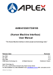
Accessible current measured to EN 61010
The accessible current must not exceed 3.5 mAmps in single fault condition (interrupted
protection earth wire)! In accordance with the EN61010, IEC1010 and UL3101 such a fault
condition can be reproduced by the following measuring circuit.
Steckergehäuse / plug-in casing
1500 Ω
5%
0,22µF
5%
10k Ω
5%
0,022µF
5%
mV
AC
500 Ω
1%
L1
L2
L3
N
PE
Körperstrom:
I [mA] = U [mV] / 500:
accessible current:
Umax = 1750mV ≡ I max = 3,5mA
Spezifaktionen für Meßgerät
- TRMS, DC - 5kHz oder mehr
- Eingangswiderstand > 1MΩ
- Toleranz 5% oder besser
- Crest Faktor 5 oder besser
Edition: 02
18.04.02 MH
Service
Page: 2-10
Specifaction for the meter
- TRMS, DC - 5kHz or more
- Input resistance > 1MΩ
- Tolerance 5% or better
- Crest Factor 5 or better
Cryofuge 6000i/8500i
Service
3.
FUNCTIONAL DESCRIPTION
3.1
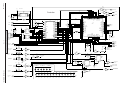
Block Functions
The Cryofuge 6000i/8500i is a microprocessor controlled and programmable floor standing
centrifuge with cooling plant and induction drive motor.
Following boards and components are located inside the unit (see also block diagram section 4
page 4-1):
Mains switch S1.
Mains input angle plate with fuses F1, F2, contactors K2, K3 and hour counter h.
Main board with central processor and ASIC80 component.
Indication board with key and display processor (SEPACONTROL programming) with key
switch for protection of all program parameters.
Serial interface board (RS 232) with plug connection for transferring the operational
parameters to a PC or Heranet system.
Driving stage for mains contactor K2
Main security path with protection for motor overtemperature F4, thermal compressor overload
F3 and overpressure of cooling plant F5.
Noise filter board.
Three phase induction drive motor with an integrated thermal overtemperature switch (cut-out
at 140°C).
Speed detection board is mounted underneath the drive motor.
Imbalance switch S6 mounted aside and in front of the drive motor (for adjustment see section
2 page 2-9).
Two lid lock assemblies each with motor locking system and integrated micro switches (S2, S3
and S4, S5).
Temperature sensor V1 (PT100).
Driving stage for compressor contactor K3 (cuts in compressor M2).
Heating element as brake resistor R1 with integrated fan M6 (mounted behind the casing's
back panel).
Three more Fans for cooling
a) of condenser, drive and compressor (M3)
b) of condenser also (M4, not used for models with water cooling)
c) of power electronics on main board (M5)
Edition: 01
26.12.01 MH
Functional Description
Page: 3-1
Cryofuge 6000i/8500i
Service
3.2
Contactor Plate (Mains Input)
The following components are mounted on an angle plate, they are accessible after opening the
front door (see also wiring connection diagram in section 4 page 4-9 from right to left):
Terminal for protection earth (PE) connection of mains cable (yellow green).
Terminal for neutral line (N) of mains cable (blue, 400 V version only).
Screw fuse F2 (6 Amp slow blown) for protection of control circuit connected to mains phase
L2 (point 3 on mains contactor) via mains switch S1.
(Second 6 Amp fuse slow blown at 3 x 230 V units)
Screw fuse F1 (20 Amp slow blown) for protection of DC intermediate circuit for the drive's
power electronics connected to mains phase L1 via noise filter board.
(Second 20 Amp fuse slow blown at 3 x 230 V units)
Mains contactor K2 with 3 phased mains connection (points 1,3,5) to supply
1.) DC intermediate circuit for drive's power electronics on phase L1 (point 2)
2.) 3 pole compressor contactor K3 (terminal 2,4,6 and 1,3,5 supply via mains
contactor) to switch the compressor ON and OFF via the thermal over current fuse F3
(manual reset).
Thermal over current fuse F3 attached on compressor contactor's output to protect the
compressor indirectly for thermal overload (part of the mains security path, points 95,96).
Selected to running current of the compressor
Two double RC combinations are fixed with tape (bilateral adhesive) on both sides of the
compressor contactor to reduce the voltage spikes when switching the compressor ON and
OFF (bypassing K3 and F3 contacts).
Hour counter h is parallel connected to the main contactor's coil to determine the operational
time when the centrifuge is switch ON and the lid is closed. This is generally the possible
condition for the compressor's operation (standstill cooling).
Edition: 01
26.12.01 MH
Functional Description
Page: 3-2
Cryofuge 6000i/8500i
Service
3.3
Main Board Functions
The main board is mounted beneath the operational panel behind the unit's back wall. The
components on main board are arranged in following groups (see wiring diagram).
Triac stage for coil of compressor contactor K3
Triac stage for fan M4 of cooling plant (condenser)
Triac stage for both parallel connected lid solenoids Y1 and Y2 (old mechanical latch)
Triac stage for three parallel connected fans (M3 for condenser and drive, M5 for electronics
on main board and M6 for brake resistor)
Triac stage for coil of main contactor K2 and hour counter h via main security path (F3, F4
motor overtemperature switch and F5 high pressure control switch)
Driver of new style motor latch system
Noise filter block (in interaction with the external noise filter board) for suppression of radio
interference, caused by the fast switching power electronics (<10 kHz), in accordance with the
German Regulation VDE 871, grade B
Bridge rectifier for DC intermediate circuit supplying brake control path and frequency
converter
Power pack for 3 different low voltage levels
Microcontroller (central processing unit) in interaction with ASIC80 functions for frequency
converter, speed and imbalance detection, temperature measuring and calibration
3.3.1 Power Pack
Transformer T1 with 2 different secondary coils, each connected to bridge rectifiers and voltage
regulators used for the following circuits:
1.) U1 = 5V:
supplies central processor, key and indication board and temperature
measuring circuit
reference potential: connected to protective conductor (GND)
2.) U2 = 12V:
supplies the circuits of speed measuring and imbalance detection
reference potential: GND2
Transformer T2 generates the low voltage supply for the power electronics:
3.) U3 = 15V:
Edition: 01
26.12.01 MH
a) contacts of relay K1 (pre-loading of intermediate circuit)
- on troubles "Err. 23" will be displayed
b) and all lid switches (S2,S3,S4,S5)
- on troubles "OPEn" at standstill and "LId" during rotation will be displayed
reference potential: UD-
Functional Description
Page: 3-3
Cryofuge 6000i/8500i
Service
3.3.2 Intermediate Circuit with Brake Path and Frequency Converter
The DC intermediate circuit serves as an energy store between the AC power input and the
transmitted motor performance.
The intermediate circuit consists of a bridge rectifier and 12 parallel connected reservoir capacitors
which are softly charged at the beginning over heavy-duty resistors (R61 and R100 parallel
connected). When the capacitor's loading has reached the defined value, the resistors are
bypassed by the relay K1 to supply frequency converter with maximum main power during
operation.
Brake Path
Electrical power is fed back into the intermediate circuit during motor deceleration (motor acts as
generator). This braking power is transformed into heat by brake resistor R1 (terminal XD) so that
the intermediate circuit voltage does not rise to an excessive level (see section 2 - test points on
main board).
The brake resistor R1 is switched into the intermediate circuit by a fast switching transistor. This
transistor is voltage dependent controlled by a self-acting stage (closed loop).
Frequency Converter
The motor is 3-phased provided with chopped direct voltage blocks. These blocks are variable in
frequency and pulse width modulation and are dephased to 120° between the motor windings.
Beginning with low frequency and small pulse width chopped blocks, both parameters will be
increased up to the operators set speed. By this variation the acceleration power of the drive motor
can be effected. For deceleration the frequency and pulse width parameters will be reduced. The
frequency converter is dynamically and absolutely protected against overcurrent and overvoltage
and also absolutely protected against excessive temperature.
When exceeding one of the absolute values (overcurrent, overvoltage or excessive temperature),
the message "Err.08" will be displayed.
3.3.3 Microcontroller (Central Processing Unit)
The controller block includes the central processor unit (CPU) P87C51FC and two of the data
storage (NV-RAMs) 93S66 with the software identification No's. for:
CPU:
0599
(second displayed No. in speed field)
1. NV-RAM: 7571
(third displayed No. in speed field) 7572 in CF 8500i only
2. NV-RAM: 7573
(fourth displayed No. in speed field)
The second parts of these No.'s (displayed in the time field) will be upgraded if necessary.
The ROM with control program is integrated in the CPU. The most important operating parameters
(e.g. the maximum data or the last operator settings) are stored in the non volatile (NV) -RAM.
The CPU co-operates with the ASIC 80 component via the 8 bit data bus and some control lines.
The ASIC 80 is a specially designed integrated circuit for the driving of Kendro centrifuges (with
induction motors), containing additional functions for speed and temperature measuring and
electronics protection.
Edition: 01
26.12.01 MH
Functional Description
Page: 3-4
Cryofuge 6000i/8500i
Service
3.3.4 Latch Control-system
The mainboard allows a controlling of the new electrical latch system with current software (CPU
599) and controlling of the old mechanical latch with old software (CPU 498) as well.
Note! The new Software does not control the old latch system.
Electrical latch
Both latches are connected to the board via terminal XC1 and XC2.
Each latch will be driven forward and backward via a relay by a special driver IC which changes the
polarity of the voltage depending on status of the wanted operation - open or close the door.
The activating of the door latches is several times protected by addition status controls of the CPU.
The door can only be opened if the speed is “0” and the lid opening button was pushed.
Mechanical latch
These mechanical latches are connected at the terminal XC. They are controlled by a triac which is
fired via photodiac by CPU. Two tachogenator signal trigged flip-flops prevent an opening of the
door whilst rotor is spinning.
3.3.5 Temperature measurement
The temperature will be detected by a PT 100 temperature sensor.
Two reference resistors 100 ohm = 0°C and 120 ohm = 50°C will give the reference value. The
auto-calibration is done by the CPU which controls an analogue switch where the signals will be
transferred to a voltage/frequency converter. This select signals to the switch IC will come from the
ASIC TEMP_1 and TEMP_2.
3.4
Key and Indication Board
The SEPACONTROL key and indication board is mounted behind the operational panel.
A special microcontroller (P87C51FC) is located on this board controlling the 7 segment displays,
the control key LEDs and the operating keys
The communication with the central processor on the main board takes place via serial data lines in
both directions (plug XI).
The reading of the keys and the displaying of values takes place by multiplex operation. All
operational parameters and user programs are stored unlimited in 6 NV-RAMs (type 93C46).
The constant identification No. of the key board processor is 0497 (first displayed No. in speed
field). There is a second No. displayed in the time field at the same time. This version No. is subject
of the permanently technical outgrowth and will be counted up at any program changes on CPU or
parameter changes on NV-RAMs.
3.5 Speed Detection Board
The speed detection takes place opto-electronically through a slit in the motor shaft.
A light-emitting infrared diode and a photo-transistor are mounted on the speed detection board
and located on opposing sides of the motor shaft
So 2 trapezoidal pulses per motor revolution are generated and transformed into stable rectangle
pulses (Schmitt trigger circuit on board), by which the micro controller calculates the real rotor
speed or rcf value.
The speed detection board is connected to the main board via the 3-pin plug XW.
Edition: 01
26.12.01 MH
Functional Description
Page: 3-5
Cryofuge 6000i/8500i
Service
3.6 Imbalance switch
If abnormal imbalance of the rotor occurs the imbalance switch will be triggered by the moving
motor. The switch closes and this signal will be given to the CPU which detects this as
“imbalance”
The connection to the switch is made of 4-pole wiring which allows a check of the cable for
defect. In this case the imbalance signal will also be displayed.
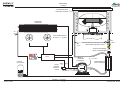
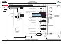
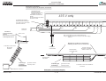
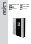
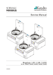
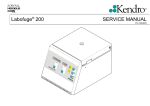
3.7 Cooling plant
The Cryofuge is equipped with a high-grade cooling plant, to meet it’s requirements of driving
power and compact design. The CFC free refrigerant R404A evaporates at low temperatures
(≤ -20°C) and absorbs through this the frictional heat from chamber produced by the spinning
rotor. Two fans serve for even air flow through condenser so that the refrigerant’s condensing
temperature is kept on a low level.
A condenser serves for essential under-cooling of the condensed refrigerant to ensure an
optimum evaporation and a perfect operation of the expansion valve. To maintain low
evaporation and resultant condensation temperatures on one hand and to support the starting
procedure of the compressor on other hand, a thermostatic expansion valve is used.
The minimum achievable sample temperatures are depending on speed, rotor type and a little
on ambient temperature. After a compensating time (at max speed – 3 hours) as optimal result,
the rotor has reached the selected set temperature within a tolerance of ± 2K.
Edition: 01
26.12.01 MH
Functional Description
Page: 3-6
Cryofuge 6000i/8500i
Kälteanlage
Cooling
Verdampferkessel
evaporator chamber
Verflüssiger
condenser
J
37 45°C
Lüfter Kühlmaschine
fans for cooling
2.2 plant
-26 -16°C
thermostatisches Expansionsventil
thermostatic expansion valve
-45 +30°C
TC
Trockner+Schauglas
Dryer+Inspectionglas
CPU
1
R404A
Verdichter
compressor
Sammler
accumulator
Druckwächter
pressure
switch
2.3
p0 = 1,7 bar
Wärmetauscher
heat exchanger
28bar 18bar
c.o. c.i.
>P
114 - 118°C
"E-23" p = 13,8 bar
7 - 8°C
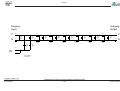
Fließbild / Flowchart
07.05.01 MH
3-7
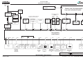
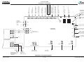
CRYOFUGE 6000i/8500i
SCHALTPLÄNE
SCHEMATIC DIAGRAMS
Netz
mains
3
XJ
Schlüsselschalter
key switch
XJ
Tasten-und Anzeigenplatte
key and indication board
Netzschalter
mains switch
S1
Hauptschütz
main contactor
K2
3
KM-Schütz
compressor
contactor K3
Deckelschloss
Latch
Left
Right
2 Impulse pro Motorumdrehung
2pulses per motor revolution
F2
Motor M7
F1
Unwuchtschalter
imbalance
switch
Kühlmaschine
compressor M2
Kurbelwannenheizung
crankcase
filament
Drehzahlerfassungsplatte
speed detection
board
S6
Temperatursensor
temperature
sensor
V1
nicht belegt
not used
XI
S5
S3
S6
S4
S7
XY
XZ
XY
X2
Motor M8
S2
XZ
RS-232
Schnittstelle
interface
Bedienplatte
operating panel
X1
Option
Funkentstörplatte
noise filter board
XE
XT
L
N
XW
XL
XU
XC 1
XC 2
XA
XI
PE
Hauptplatte
main board
XM1
XM2
Motor
XB
XM3
F4
M1
Motorübertemperatur
motor over
temperature
XH
Motor/KM
Lüfter
motor/compr.
fan
M3
XF
FET-Lüfer
fan for
electronics
M5
XN
XS
Lüfter Bremswiderstand
fan of braking
resistor
M6
F3
XO
XP
F5
P
K2
TsÜ (KM)
thermal
fuse
Pressostat
overpressure
switch
Ansteuerung
Hauptschütz
mains contactor
coil
XC
XK
Deckelspulen
lid solenoids
KM-Lüfter
fan for cooling
plant
M4
Y1 , Y2
Old/alte
*
(entfällt bei Wasserkühlung
not used with water
cooling
XG
XD
Bremswiderstand
brake resistor
K3
R1
Ansteuerung
Kühlmaschine
compressor
coil
Legende / legend
Steckverbindung / plug connection
Schraubverbindung / screwing connection
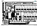
Blockschaltbild / Block Diagram
23.04.01 MH
4-1
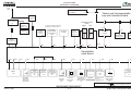
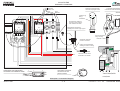
3 x 400 V + N + PE CRYOFUGE 6000i/8500i
SCHALTPLÄNE
SCHEMATIC DIAGRAMS
Netz
mains
3
XJ
Schlüsselschalter
key switch
XJ
Tasten-und Anzeigenplatte
key and indication board
F3
Netzschalter
mains switch
S1
F4
Hauptschütz
main contactor
K2
F1
3
KM-Schütz
compressor
contactor K3
Deckelschloss
Latch
Left
Right
2 Impulse pro Motorumdrehung
2pulses per motor revolution
Motor M7
F2
Unwuchtschalter
imbalance
switch
Kühlmaschine
compressor M2
Kurbelwannenheizung
crankcase
filament
Drehzahlerfassungsplatte
speed detection
board
S6
Temperatursensor
temperature
sensor
V1
nicht belegt
not used
XI
S5
S3
S6
S4
S7
XY
XZ
XY
X2
Motor M8
S2
XZ
RS-232
Schnittstelle
interface
Bedienplatte
operating panel
X1
Option
Funkentstörplatte
noise filter board
XE
XT
L
N
XW
XL
XU
XC 1
XC 2
XA
XI
PE
Hauptplatte
main board
XM1
XM2
Motor
XB
XM3
F4
M1
Motorübertemperatur
motor over
temperature
XH
Motor/KM
Lüfter
motor/compr.
fan
M3
XF
FET-Lüfer
fan for
electronics
M5
XN
XS
Lüfter Bremswiderstand
fan of braking
resistor
M6
F3
XO
XP
F5
P
K2
TsÜ (KM)
thermal
fuse
Pressostat
overpressure
switch
Ansteuerung
Hauptschütz
mains contactor
coil
XC
XK
Deckelspulen
lid solenoids
KM-Lüfter
fan for cooling
plant
M4
Y1 , Y2
Old/alte
*
(entfällt bei Wasserkühlung
not used with water
cooling
XG
XD
Bremswiderstand
brake resistor
K3
R1
Ansteuerung
Kühlmaschine
compressor
coil
Legende / legend
Steckverbindung / plug connection
Schraubverbindung / screwing connection
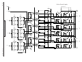
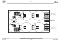
Blockschaltbild / Block Diagram
23.04.01 MH
4-2
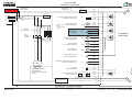
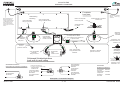
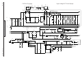
3 x 230 V + PE CRYOFUGE 6000i/8500i
SCHALTPLÄNE
SCHEMATIC DIAGRAMS
Netz
mains
XJ
Schlüsselschalter
key switch
XJ
Tasten-und Anzeigenplatte
key and indication board
Netzschalter
mains switch
S1
Hauptschütz
main contactor
K2
KM-Schütz
compressor
contactor K3
Deckelschloss
Latch
Left
Right
2 Impulse pro Motorumdrehung
2pulses per motor revolution
F2
Motor M7
F1
Unwuchtschalter
imbalance
switch
Kühlmaschine
compressor M2
Drehzahlerfassungsplatte
speed detection
board
S6
Temperatursensor
temperature
sensor
V1
nicht belegt
not used
XI
S5
S3
S6
S4
S7
XY
XZ
XY
X2
Motor M8
S2
XZ
RS-232
Schnittstelle
interface
Bedienplatte
operating panel
X1
Option
Funkentstörplatte
noise filter board
XE
XT
L
N
XW
XL
XU
XC 1
XC 2
XA
XI
PE
Hauptplatte
main board
XM1
XM2
Motor
XB
XM3
F4
M1
Motorübertemperatur
motor over
temperature
XH
Motor/KM
Lüfter
motor/compr.
fan
M3
XF
FET-Lüfer
fan for
electronics
M5
XN
XS
Lüfter Bremswiderstand
fan of braking
resistor
M6
F3
XO
XP
F5
P
K2
TsÜ (KM)
thermal
fuse
Pressostat
overpressure
switch
Ansteuerung
Hauptschütz
mains contactor
coil
XC
XK
Deckelspulen
lid solenoids
KM-Lüfter
fan for cooling
plant
M4
Y1 , Y2
Old/alte
*
(entfällt bei Wasserkühlung
not used with water
cooling
XG
XD
Bremswiderstand
brake resistor
K3
R1
Ansteuerung
Kühlmaschine
compressor
coil
Legende / legend
Steckverbindung / plug connection
Schraubverbindung / screwing connection
Blockschaltbild / Block Diagram
23.04.01 MH
4-3
Single Phase CRYOFUGE 6000i/8500i
SCHALTPLÄNE
SCHEMATIC DIAGRAMS
3 x 400 V+ N+PE
Hauptschütz
mains contactor
Netzschalter
mains switch
F2 6AT
S1
XT/1
3
XT/2
4
F1 20AT
L1
L2
L3
N
1
2
3
4
5
XG/1
6
Ansteuerung-Kühlmaschinenschütz
compressor contactor coil
K3
Lüfter-Kühlmaschine
fan for cooling plant
M4
XG/2
K2
PE
*
KM-Schütz
compr. Contacor
1
3
5
2
4
6
(entfällt bei Wasserkühlung
not used with water
cooling
XK/2
See Note
K3
TSÜ
thermal F3
overload
XK/1
XC/1
Deckelspulen
lid solenoids
Y1/Y2
Lüfter-Bremswiderstand
fan of brake resistor
M6
Lüfter-Motor/KM
fan for motor/compressor
M3
Lüfter-Elektronik
fan for electronics
M5
XC/2
Hauptplatte
main board
XS/1
XS/2
XH/1
XH/2
XF/1
M2
XF/2
XB/1
Motor-Übertemperatur
motor overtemperature
F4
Thermischer Überstromauslöser (TSÜ)
thermal overcurrent cut off
F3
XB/2
XN/1
XN/2
XO/1
Kühlmaschine mit Kurbelwannenheizung
compressor incl. crankcase
filament
Pressostat
overpressure switch
F5
P
XO/2
XP/1
Ansteuerung Hauptschütz
mains contactor coil
h
K2
Betriebsstundenzähler/hour counter
Funkentstörplatte
noise filter board
XP/2
L1
1
N
2
PE
Stromlaufplan / Schematic Diagram
25.04.01 MH
4-4
3 x 400 V + N + PE
CRYOFUGE 6000i/8500i
SCHALTPLÄNE
SCHEMATIC DIAGRAMS
Hauptschütz
mains contactor
F3 6AT
Netzschalter
mains switch
S1
XT/1
3 x 230 V + PE
F1 20AT
L1
L2
L3
3
XT/2
1
2
3
4
5
F4 6AT
6
4
XG/1
Ansteuerung-Kühlmaschinenschütz
compressor contactor coil
K3
Lüfter-Kühlmaschine
fan for cooling plant
M4
XG/2
F2 20AT
K2
PE
*
KM-Schütz
compr. Contacor
1
3
5
2
4
6
(entfällt bei Wasserkühlung
not used with water
cooling
XK/2
See Note
K3
TSÜ
thermal F3
overload
XK/1
XC/1
Deckelspulen
lid solenoids
Y1/Y2
Lüfter-Bremswiderstand
fan of brake resistor
M6
Lüfter-Motor/KM
fan for motor/compressor
M3
Lüfter-Elektronik
fan for electronics
M5
XC/2
Hauptplatte
main board
XS/1
XS/2
XH/1
XH/2
XF/1
M2
XF/2
XB/1
Motor-Übertemperatur
motor overtemperature
F4
Thermischer Überstromauslöser (TSÜ)
thermal overcurrent cut off
F3
XB/2
XN/1
XN/2
XO/1
Kühlmaschine mit Kurbelwannenheizung
compressor incl. crankcase
filament
Pressostat
overpressure switch
F5
P
XO/2
XP/1
Ansteuerung Hauptschütz
mains contactor coil
h
K2
Betriebsstundenzähler/hour counter
Funkentstörplatte
noise filter board
XP/2
L1
1
N
2
PE
Stromlaufplan / Schematic Diagram
25.04.01 MH
4-5
3 x 230 V+ PE
CRYOFUGE 6000i/8500i
SCHALTPLÄNE
SCHEMATIC DIAGRAMS
Single phase
Hauptschütz
mains contactor
Netzschalter
mains switch
F2 6AT
S1
XT/1
3
XT/2
4
F1 20AT
L1
N
1
2
3
4
5
XG/1
6
Ansteuerung-Kühlmaschinenschütz
compressor contactor coil
K3
Lüfter-Kühlmaschine
fan for cooling plant
M4
XG/2
K2
PE
*
KM-Schütz
compr. Contacor
TSÜ
thermal
overload
1
3
5
2
4
6
(entfällt bei Wasserkühlung
not used with water
cooling
XK/1
XK/2
See Note
K3
XC/1
Deckelspulen
lid solenoids
Y1/Y2
Lüfter-Bremswiderstand
fan of brake resistor
M6
Lüfter-Motor/KM
fan for motor/compressor
M3
Lüfter-Elektronik
fan for electronics
M5
XC/2
F3
XS/1
Hauptplatte
main board
XS/2
XH/1
XH/2
XF/1
M2
XF/2
XB/1
Motor-Übertemperatur
motor overtemperature
F4
Thermischer Überstromauslöser (TSÜ)
thermal overcurrent cut off
F3
XB/2
XN/1
XN/2
XO/1
Pressostat
overpressure switch
Kühlmaschine
compressor
F5
P
XO/2
XP/1
Ansteuerung Hauptschütz
mains contactor coil
h
K2
Betriebsstundenzähler/hour counter
Funkentstörplatte
noise filter board
XP/2
L1
N
1
2
PE
Stromlaufplan / Schematic Diagram
25.04.01 MH
4-6
Single Phase CRYOFUGE 6000i/8500i
SCHALTPLÄNE
SCHEMATIC DIAGRAMS
Hauptplatte
main board
L1
L1
1
UD+
Funkentstörung
noise fliter
2
3
Zwischenkreis
intermediate circuit
N
N
Umrichter
frequency converter
UD-
Bremschopper
brake chopper
XI/1-6
L2
Prozessor
CPU
5V
GND
X1/1-6
RS-232
Schnittstelle
interface
24V
12V
Schlosssteuerung
latch control
GND
Unwuchterkennung
imbalance
detection
Drehzahlmessung
speed measuring
Temperaturmessung
temperature
measuring
Schlüsselschalter
key switch
X2/1-6
YJ/1-4
XI/1-6
15V
4
N
UD-
Tasten - u. Anzeigenplatte
key and indication board
XA/1
XC/ 2
XA/2
S4
12 3
XC/1
XW/1
2
XE/1
3
2
3
4
XZ/1-5
XU/1
XU/2
XD/1
XD/2
XM/1
XM/2
4
2
1
1
2
3 4
S7
Deckelschalter
in Verschlüssen
lid switches
inside latches
S5
Schloss links
latch left
M7
S2
Drehzahlerfassungsplatte
speed detection
board
XY/1-3
XM/3
Bedienplatte
operating panel
M8
25.04.01 MH
4
S6
3
S3
21
4
3
Option
PT 100
R1
S6
Unwuchtschalter
imbalance switch
Temperaturfühler
temperature sensor
Schloss rechts
latch right
Bremswiderstand
brake resistor
M1
Motor
motor
Stromlaufplan / Schematic Diagram
4-7
CRYOFUGE 6000i/8500i
Deckelschloss 2 links
Latch 2 left
Deckelschalter S2/S3 S4/S5
lid switches
Deckelschloss 1rechts
Latch 1 right
*
Ansteuer. Schütz KM K3
contactor coil for compr.
condenser fan M4
*
(not used on units with water cooling)
(entfällt bei Wasserkühlung)
Lüfter Kühlmaschine M4
Deckelspulen Y1/Y2 alte Ausführung
lid solenoids old Version
Lüfter Motor/KM M3
fan for motor/compr.
Lüfter Elektronik
fan for electronics M5
Lüfter Bremswiderstand
fan of brake resistor M6
Ansteuer. Hauptschütz
coil mains contactor K2
TSÜ F3
thermal overcurrent
Pressostat F4
over pressure switch
SCHALTPLÄNE
SCHEMATIC DIAGRAMS
Abschirmungen
screenings
Drehzahl
speed
Anzeigeplatte
indication board
Temperaturfühler
temperature sensor
XN
Motorübertemperatur
overtemperature
switch
XS
XF
XH
XC
XK
XG
XB
XA
XC 1
XC 2
Hauptplatte
main board
PE
ws
WHT
sw
BLK
XI
XE
XT
N
PE
P
XP
L2
Netz
mains
N
XO
N
XW
Netzumrichter
frequency converter
L1
Unwuchtschalter S6
imbalance switch
Drehzahlerfassungsplatte
speed detection board
Tasten- u. Anzeigenplatte
(RS-232 Schnittstelle)
XI
key and indication board
(RS-232 interface)
XU
Temperaturfühler
temperature sensor
PE
Funkentstörplatte
noise filter board
P
XM1
XD1
N
ws
WHT
ws
WHT
26.04.01 MH
XM3
XD2
sw
BLK
sw
BLK
Kurbelwannenheizung
Kühlmaschine
crankcase filament
compressor
XM2
Bremswiderstand
brake resistor R1
Motorkabel
motor wires
W
V
U
Hauptschütz
K2
mains contactor
Klemmplan / Connection Diagram
4-8
CRYOFUGE 6000i/8500i
SCHALTPLÄNE
SCHEMATIC DIAGRAMS
Netzkabel
Power cord
gn/ge
GRN/YEL
bl
BLU
4
Anschlüsse Deckelschloß
connections of lid lock assembly
Anschluß Programmschalter
connection of program switch
Alt/old
Verdrahtung
Wiring
70003688
5
4
C
2
1
2A
1A
1 3
h
5 13
1 3
K3
2
4
5 13
20AT
2
4
S1
4
2
Y1
Schutzleiter Nr.70907513
protection earth conductor
AE8 AWG12/150 BKS2
6AT
K2
6 14
1
S2
1
Erdungsbolzen-Netzwinkel
earthing bolt of mains angle support
6 14
4
2
1
1B
95
2
2B
96
4
8
7
Verdr. Deckelschloß
wiring of lid lock
70907503
6
9
6
Schutzleiter 70907514
protective conductor
Erdung auf Gehäuseboden
earthing on bottom of casing
S2/S5
Not used
S4/S7
Schraube / screw M4x10
2xScheibe F/ fan washer
S3/S6
M7/M8
Anschlüsse Unwuchtschalter
connections of imbalance switch
Com
1
3
No
Nc
Anschlüsse Pressostat
connections of over
pressure switch
2
1
2
4
3
4
6
5
1
2
Verschluss/Latch
neu/new
Klemmplan / Connection Diagram
26.04.01 MH
4-9
3 x 400 V + N + PE
CRYOFUGE 6000i/8500i
SCHALTPLÄNE
SCHEMATIC DIAGRAMS
Black
Netzkabel
Power cord
Red
gn/ge
GRN/YEL
White
2
Anschlüsse Deckelschloß
connections of lid lock assembly
Anschluß Programmschalter
connection of program switch
4
3
Alt/old
Verdrahtung
Wiring
70003688
5
4
C
2
1
2A
1A
1
S1
4
2
Y1
S2
1 3
h
5 13
1 3
K3
2
4
5 13
20AT
20AT
6AT
6AT
1
K2
6 14
2
4
4
2
6 14
1
1B
95
2
2B
96
4
6
7
8
6
Main
switch
Erdungsbolzen-Netzwinkel
earthing bolt of mains angle support
9
Verdr. Deckelschloß
wiring of lid lock
70907503
Schutzleiter 70907514
protective conductor
1 3
2 4
Erdung auf Gehäuseboden
earthing on bottom of casing
S2/S5
S4/S7
Schraube / screw M4x10
2xScheibe F/ fan washer
S3/S6
M7/M8
Anschlüsse Unwuchtschalter
connections of imbalance switch
Com
1
3
No
Nc
Anschlüsse Pressostat
connections of over
pressure switch
nc 1
Black
Red
2
4 no
3
4
6
5
1
2
White
2 com
Verschluss/Latch
neu/new
Klemmplan / Connection Diagram
26.04.01 MH
4 - 10
3 x 230 V + PE
CRYOFUGE 6000i/8500i
SCHALTPLÄNE
SCHEMATIC DIAGRAMS
Netzkabel
Power cord
BLACK
GREEN
WHITE
4
Anschlüsse Deckelschloß
connections of lid lock assembly
Anschluß Programmschalter
connection of program switch
Alt/old
Verdrahtung
Wiring
70003688
5
4
C
2
1
2A
1A
1 3
h
5 13
1 3
K3
2
4
5 13
20AT
2
4
S1
4
2
Y1
Schutzleiter Nr.70907513
protection earth conductor
AE8 AWG12/150 BKS2
6AT
K2
6 14
1
S2
1
Erdungsbolzen-Netzwinkel
earthing bolt of mains angle support
6 14
4
2
1
1B
95
2
2B
96
4
8
7
Verdr. Deckelschloß
wiring of lid lock
70907503
6
9
6
Schutzleiter 70907514
protective conductor
Erdung auf Gehäuseboden
earthing on bottom of casing
S2/S5
S4/S7
Schraube / screw M4x10
2xScheibe F/ fan washer
S3/S6
M7/M8
Anschlüsse Unwuchtschalter
connections of imbalance switch
Com
1
3
No
Nc
Anschlüsse Pressostat
connections of over
pressure switch
2
1
2
4
3
4
6
5
1
2
Verschluss/Latch
neu/new
Klemmplan / Connection Diagram
26.04.01 MH
4 - 11
Single Phase
CRYOFUGE 6000i/8500i
SCHALTPLÄNE
SCHEMATIC DIAGRAMS
Frontplatte
front plate
Abschirmung
screening
Beim Festschrauben der
Rückwand Kabelschuh
zwischen Sechskantbolzen
und Rückwand klemmen
When closing the back
panel put the solderless
earthing eye on the screw’s
thread
Verdr. Bedienplatte
wiring of front panel
Bolzen auf Frontplatte
bolt on front plate
Verdr. Anzeigenplatte
wiring of indication board
2xSchutzleiter / protective conductor
140mm lang / length
AWG12
70907532
3xFächerscheibe / fan washer
1x Mutter / nut
Schlüsselschalter
key switch
XI
XZ
XJ
Armaflex 10x5cm unter Ringkern
auf Schaltpultboden kleben
glue Armaflex under toroidel core
on panel’s bottom
Ferrit-Ringkern
36x23x15 violett
toroidel core violet
Verdr.
Bedienplatte
Nr. 70907523
front panel
2xMasseband
earthing braid
70907039
1x Schraube / screw M4x12
2x Fächerscheibe / fan washer
1x Mutter / nut M4
Schutzleiter
70907514
protective conductor
Verdr. Anzeigenplatte
wiring indication board
X1
X2
Verdr. Schnittstelle
70907522
wiring of interface
SchnittstellenPlatte
interface board
70907508
Aufbau Erder
mounting of
earthing plug
Schutzleiter 70907514
protective conductor
Rückwand Schaltpultgehäuse
back wall of panel casing
Schutzleiteranschlüsse
connections of protective conductors
Funkentstörplatte
noise filter board
70907518
*(entfällt bei Wasserkühlung)
*(not used on units with water cooling)
Lüfter-Kondens.
condenser fan
Deckelschlösser
lid switches
Leistungsplatte
main board
70907518
Lüfter-Kompr./Motor
fan for compr./motor
Bremslüfter
fan of brake resistor
70004891
Lüfter-Elektronik
fan for electronics
70004891
Flachstecker / tripple plug
Schraube / screw M4x10
2xScheibe F / fan washer
Schutzleiter
protective conductors
Tür-Gehäuse
front door
70907514
Kühlmaschine 70004984
compressor
Rückwand
back wall
70004891
Klemmplan / Connection Diagram
26.04.01 MH
4 - 12
CRYOFUGE 6000i/8500i
SCHALTPLÄNE
SCHEMATIC DIAGRAMS
Klemmplan Vorschalttrafo
Connection Diagram for Step Down Transformer
Vorhandenen Erder
austauschen gegen:
change present grounding
receptacle as follows:
Gewindestift / threaded bolt
M4x30
5x Fächerscheibe / fan washer
4x Mutter / nut M4
415 V only
an Netzkabel-Schutzleiter
Kabelschuh KS3 anschlagen
fix a cable eye Ks3 onto mains’
protective conductor
N
gn/ge
GRN/YEL
460V
440V
bl
BLU
415V 380V 460V
440V
sw
BLK
415V 380V 460V
440V
415V 380V 400V
br
BRN
sw
BLK
1
400V
400V
2
3
Netzleitung
mains line
Ferritkerne
in Motorübertemp.
Leitung
ferrite cores on motor’s
overtemperature line
Motor / motor
Verdr. Vorschalttrafo (nur für 415V Netzspannung)
wiring of step down transformer (only for 415V mains supply)
70907517
Befestigung Ferritkerne in Motorleitung
attaching of ferrite cores on motor lines
4x Ferritkern / ferrite cores
26x14,5x20
20170316
Netzchassis
mains chassis
Zwischenboden
intermediate base
Schelle / clamp 6,5
Schraube / screw M4x8
Scheibe / washer 4,3
Leistungsplatte
main board
4 Windungen
4 windings
gemeinsam wickeln
commonly coiled
Motor
motor
3 Windungen
3 windings
gemeinsam wickeln
commonly coiled
4x Ferritkern / ferrite cores 36x23x15
20170318
Kabelkanal / cable duct
Klemmplan / Connection Diagram
26.04.01 MH
4 - 13
CRYOFUGE 6000i/8500i
08.05.01 MH
230 V
18 V
230 V
15 V
Service
F1
Bestückungsplan Hauptplatte / Component Plan mainboard
4 - 14
CRYOFUGE 6000i/8500i
08.05.01 MH
Leistungsteil
Bremse/Strommessung
Versorgung
UD+
UD1-
UD+
UD+
UD1-
L1
L1
N1
N1
15V+
15V+
UD-
UD-
15V+
UD/UEBERSTROM
/UEBERSPG
56631A05
24V+
Controller
/UEBERSPG
/UEBERSTROM
Ansteuerungen
N
N
L
L
DECKEL_OFFEN
/SCHUETZ_ON
56631A07
DECKEL_OFFEN
/SCHUETZ_ON
/DECKEL_OFFEN
24V+
/DECKEL_OFFEN
/KLOBEN
/KLOBEN
PHASE1_U
PHASE1_U
PHASE2_U
PHASE2_U
PHASE3_U
PHASE3_U
INHIBIT
Service
4 - 15
Schaltbild Hauptplatte / Wiring Diagram mainboard
12V+
INHIBIT
56631C06
Temperaturmessung
TEMP_IN
12V+
TEMP_IN
TEMP_1
TEMP_1
TEMP_0
TEMP_0
/DREHZAHL
/DREHZAHL
/UNWUCHT
/UNWUCHT
Unwucht / Drehzahl
56631A03
DECKELFREIGABE
KUEHLMASCHINE
/LUEFTER_KM
/DECKELSPULE
DECKELFREIGABE
KUEHLMASCHINE
/LUEFTER_KM
/DECKELSPULE
CRYOFUGE 6000i/8500i
/LUEFTER
/LUEFTER
/SCHUETZ
/SCHUETZ
56631C08
56631B04
56631A02
08.05.01 MH
Tachogenerator and Imbalance
12V+
/DREHZAHL
Speed Signal
to CPU
Drehzahlschaltung
wahlweise aktiv
oder passiv
XW
+
C167
100n
SMD
C166
10u
SMD 25V TA
1
2
3
1
2
3
R178
10k
SMD
R179
560R
SMD
R177
22k
SMD
C165
22n
SMD
Service
4 - 16
Schaltbild Hauptplatte / Wiring Diagram mainboard
R176
10k
SMD
4-Wire
Imbalance
Detector
XE
4
3
2
1
4
3
2
1
R180
560R
SMD
/UNWUCHT
Imbalance Signal
to CPU
3
1
D43
SFH6106-3
SMD
4
2
GND
GND
C1
100n
SMD
GND
CRYOFUGE 6000i/8500i
08.05.01 MH
Temperature Measurement
R153
22R
SMD
VCC
C58
100n
SMD
R48
22k
SMD
GND
8
+
2
GND
D30B
TLC272
SMD
D31
12
14
15
11
X0
X1
X2
X3
VDD
5
3
16
R51
100K
SMD
VSS
VEE
8
7
C178
7
+
74HC4052
SMD
GND
D32
LM331
Analog switch
R53
33k
SMD
COMP IN
R/C
GND
1
CURR IN
C179
6
THRES
GND
+
1u
SMD 35V TA
5
GND
F OUT
3
TEMP_IN
2
4
GND
C54
220n
Fo
R52
100K
SMD
R55
12k
SMD
GND
R56
2k7
SMD
TEMP_0
CRYOFUGE 6000i/8500i
0
0
1
1
TEMP_1
0
1
0
1
R
100R
120R
PT100
---
R54
10k
SMD
1u
SMD 35V TA
REF CUR
R57
390R
SMD
Voltage/frequency converter
7
VS
TEMP_1
TEMP_0
Y0
Y1
Y2
Y3
INH
A
B
Y
6
8
1
5
2
4
6
10
9
R45
100R
0.1%
X
R49
22k
SMD
13
+
C62
1n
SMD
2
1
XU
R50
270k
SMD
-
2
1
GND
Service
PT100
GND
-
R47
1k
SMD
R46
120R
0.1%
D30A
TLC272
SMD
1
GND
+
4
4 - 17
Schaltbild Hauptplatte / Wiring Diagram mainboard
3
C21
1000u
16V
C135
100n
SMD
C112
100n
SMD
C110
100n
SMD
GND
08.05.01 MH
VCC
Reset Controler
D49
Tl7705
SMD
REF
RESIN
CT
GND
/RD
/WR
Controller
VCC
SENSE
RESET
RESET
8
7
6
5
/LUEFTER_KM
D54C
74HC14
SMD
6
5
AD0
AD1
AD2
AD3
AD4
AD5
AD6
AD7
C104
1u
+ SMD 35V TA
VCC
/LUEFTER
D54
D74HC14
SMD
8
9
/SCHUETZ
61
62
63
64
65
66
67
68
1
2
3
4
5
6
7
8
9
C109
100n
SMD
1
2
3
4
D54B
74HC14
SMD
4
3
RESET
GND
D47
P87C54
OTP
VCC
C118
22p
SMD
31
GND
/RESET
/KLOBEN
GND
19
J1
J 11.14112
C119
22p
SMD
18
9
VCC
VCC
D8
NMC93C66
R104
4k7
SMD
VCC
NC
NC
GND
CS
SK
DI
DO
1
2
3
4
12
13
14
15
HSI
XI
6
5
4
3
2
1
6
5
4
3
2
1
HSO
HSI
TXD
RXD
GND
D48
NMC93C66
VCC
8
6
7
5
VCC
GND
Tasten- und
Anzeigeplatine
Panel
Connection
VCC
NC
NC
GND
CS
SK
DI
DO
1
2
3
4
X2
RESET
P2.0
P2.1
P2.2
P2.3
P2.4
P2.5
P2.6
P2.7
INT0
INT1
T0
T1
P1.0/T2
P1.1/T2X
P1.2
P1.3
P1.4
P1.5
P1.6
P1.7
RD
WR
PSEN
ALE/PALE/
TXD
RXD
39
38
37
36
35
34
33
32
AD0
AD1
AD2
AD3
AD4
AD5
AD6
AD7
21
22
23
24
25
26
27
28
SCHUETZ_ON
HSO
UEBERSTROM
UNWUCHT
/DECKEL_OFFEN
/DECKEL
DEFEKT
Tp7 TESTPUNKT
R107
4k7
SMD
1
2
Br7
8/9Bit
GND
17
16
29
30
11
10
10
11
12
13
14
15
16
17
18
19
20
21
22
23
24
25
26
VCC
/RD
/WR
GND
VDD
ALE
A0
A1
A2
DREHZ_IN
DREHZ_OUT
VDD
WR_6X
WR_7X
TEMP2
MODE
RESET
BIT9
INH_IN
TEST
GND
PH1_O
PH2_O
PH3_O
PH1_U
PH2_U
PH3_U
GND
VDD
TAKT55_IN
TAKT55_OUT
TAKT11_IN
PWM_IN
PWM_OUT1
PWM_OUT0
F_IN
F_OUT
D45
ASIC80
60
59
58
57
56
55
54
53
52
51
50
49
48
47
46
45
44
PHASE1_U
PHASE2_U
PHASE3_U
BR4
1
2
exor
1
2
TP5
and
BR5
Tp4
TESTPUNKT Spannung
43
42
41
40
39
38
37
36
35
34
33
32
31
30
29
28
27
1
2
3
4
5
6
7
8
P0.0
P0.1
P0.2
P0.3
P0.4
P0.5
P0.6
P0.7
EA/VP
X1
GND
INH_O1
INH_O0
UEBERSP
FEHLER
VDD
TEMP0
TEMP1
GND
INTERRUPT
TEMPERATUR
RD_5X
RD_4X
TAKT_1
TAKT_0
Q_IN
Q_OUT
Tp3
TESTPUNKT Frequenz
GND
GND
INHIBIT
TEMP_0
TESTPUNKT
/DS_MOTOR
TEMP_1
/DECKEL_OFFEN
VCC
VCC
R116
4k7
SMD
J3
J 10.000
1
VCC
C120
22p
SMD
74HC14
SMD
GND
D53E
11
74HC14
SMD
R125
470k
SMD
74HC14
SMD
74HC14
SMD
Ueberstrom-Anzeige
Overcurrent Indicator
R175
2M2
SMD
VCC
2
+
1
GND
6
R106
1M
SMD
GND
14
15
+
12
11
GND
Unconnected Parts / Power Supply
RC
Q
CX
+T
-T
R
9
8
/SCHUETZ_ON
SMD 25V TA
SMD 25V TA
SMD 25V TA
SMD 25V TA
C56
10u
+
C57
10u
+
C105
10u
+
C107
10u
+
+T
-T
10
Q
7
D50B
4
Q
6
4538
SMD
5
9
74HC132
SMD
C163
47p
SMD
VCC
VCC
C55
10u
+
R119
10k
SMD
SMD 25V TA
SMD 25V TA
6
D46A
4538
SMD
DECKELFREIGABE
DECKELFREIGABE
GND
C108
10u
+
D54E
11
10
D53F
9
CRYOFUGE 6000i/8500i
13
12
/UEBERSPG
Overvoltage
8
GND
10
74HC14
SMD
VCC
D54A
1
/DREHZAHL
Speed
2
74HC14
SMD
GND
C59
100n
SMD
C60
100n
SMD
C111
100n
SMD
C113
100n
SMD
C114
100n
SMD
C115
100n
SMD
/DECKELSPULE
Lid Control
13
74HC14
SMD
4
5
D46B
Q
CX
3
C123
100n
SMD
C124
1u
SMD 35V TA
VCC
RC
R
74HC14
SMD
D53D
VCC
C164
1u
SMD 35V TA
GND
5
R122
10k
SMD
12
GND
D53C
R124
100R
SMD
VCC
V59
LED RT
SMD
R120
1k
SMD
R121
1k
SMD
D54F
13
10
4
/UNWUCHT
Imbalance
/UEBERSTROM
Overcurrent
C122
22p
SMD
D53B
3
VCC
Ueberspannungs- oder
Hardware-Uberstrom
Anzeige
Overvoltage or
Hardware-Overcurrent
Indicator
2
DECKEL_OFFEN
Lid open Signal
R117
4k7
SMD
TEMP_IN
V60
LED RT
SMD
D53A
C116
100n
SMD
C117
100n
SMD
C121
100n
SMD
C132
100n
SMD
C133
100n
SMD
C134
100n
SMD
C146
100n
SMD
C147
100n
SMD
GND
D50C
74HC132
SMD
74HC14
SMD
KUEHLMASCHINE
COOLING CONTROL
Service
4 - 18
Schaltbild Hauptplatte / Wiring Diagram mainboard
R103
4k7
SMD
8
6
7
5
TEMP3
TEMP4
TEMP5
TE
TOUT
RD
WR
VDD
GND
D0
D1
D2
D3
D4
D5
D6
D7
R105
10k
SMD
08.05.01 MH
Current Limiting
Brake Shopper
UD+
15V+
R157
100k
2W
R38
3k3
SMD
/UEBERSTROM
Hardware-Ueberstrom
Hardware-Overcurrent
Software-Ueberstrom
Software-Overcurrent
1
4
D26
SFH617G-3
4
1
V81
BA159
D56
LED RT
SMD
R37
3k3
SMD
D28
SFH617G-3
2
3
V31
Sm4007
SMD
3
GND
C50
22n
SMD
R44
150R
R4
122k
SMD
C49
22n
SMD
SMD
L1
V80
P6KE440A
R33
220R
SMD
V33
BC817
V32
Sm4007
SMD
R152
1k5
SMD
F1
Bimetall-Schalter
Oeffner 90 Grad
C52
22n
Montage am
Kuehlkoerper
von V13
SMD
N1
R151
1k5
SMD
XD1
R40
220R
SMD
+
D7
SFH617G-3
C30
100u
25V
3
2
R130
2M2
SMD
R59
100k
2W
GND
GND
Uebertemperatur
Overtemperature
V37
BC817
R126
1M
8
3
2
+
R3
110R
SMD
1
4
D10A
TLC272
SMD
/UEBERSPG
C125
470u
35V
+
C47
100n
SMD
6
-
D10B
TLC272
SMD
2
C48
47p
SMD
7
1
R30
68k
SMD
+
3
C67
2n2
SMD
Ueberspannung
Overvoltage
4
5
C46
220n
400V
R127
10k
SMD 1%
R29
0R033
7W
V41
BUP304
V38
BC807
R128
10k
SMD 1%
UD1-
4
1
XD2
R129
1M
R32
100k
2W
V11
SM4007
SMD
R68
330R
SMD
Bremswiderstand
Brake Resistor
V39
BYT13-1000
R185
220R
SMD
Service
4 - 19
Schaltbild Hauptplatte / Wiring Diagram mainboard
V34
BC817
2
GND
V36
BC817
R42
220R
SMD
R39
220R
SMD
D52
SFH617G-3
C51
47n
SMD
GND
R43
0R033
7W
CRYOFUGE 6000i/8500i
Ueberstromerkennung
Overcurrent Recognition
UD-
08.05.01 MH
Motor Power Supply
VCC
Kuehlkoerper SK409
Montage mit Waermeleitpaste
C45
100n
SMD
15V+
GND
INHIBIT
2
D19
HCNW3120
SMD
UD+
V24
BA159
8
7
6
R93
10R
SMD
+
C37
100n
SMD
C7
100u
25V
V1
BUP304
R7
10R
SMD
V30
BUP304
V127
BYP103
C136
470n
400V MKP10
3
5
6
9
5
C2
1n
SMD
D59D
74HC14
SMD
D59C
74HC14
SMD
C137
470p
SMD
8
2
D59E
74HC14
SMD
4
11
D20
HCNW3120
SMD
8
7
6
10
R14
10R
SMD
+
C8
100u
25V
C38
100n
SMD
GND
1
2
13
12
2
D21
HCNW3120
SMD
V28
BUP304
C18
470p
SMD
C130
470p
SMD
V138
BC817
R23
4k7
SMD
R150
10R
SMD
V129
BYP103
5
D59F
74HC14
SMD
V6
BUP304
C15
100n
SMD
3
PHASE1_U
D59A
74HC14
SMD
W
BA159
Motor
V22
BA159
8
7
6
+
C39
100n
SMD
V29
BUP304
R15
C9
100u
25V
10R
R135
10R
SMD
V7
BUP304
V133
BYP103
SMD
3
D58D
74HC14
SMD
D58A
74HC14
SMD
1
5
C3
1n
SMD
R24
220R
SMD
9
8
C15
110n
SMD
D58B
74HC14
SMD
2
D22
HCNW3120
SMD
D58E
74HC14
SMD
4
11
10
8
R16
10R
SMD
+
C10
100u
25V
C40
100n
SMD
3
R22
4k7
SMD
GND
6
13
12
2
R25
220R
SMD
5
6
9
V132
BYP103
3
C4
1n
SMD
11
CRYOFUGE 6000i/8500i
13
R139
10R
SMD
V13
BUP304
V135
BYP103
C26
470p
SMD
C141
470n
400V MKP10
C138
470p
SMD
XM3
2
D24
HCNW3120
SMD
8
7
6
10
+
C42
100n
SMD
C12
100u
25V
R18
10R
SMD
V16
BUP304
R141
10R
SMD
V17
BUP304
V134
BYP103
3
R21
4k7
SMD
D57F
74HC14
SMD
2
V26
BUP304
V19
BA159
5
1
C11
100u
25V
C41
100n
SMD
8
PHASE3_U
D57A
74HC14
SMD
R17
10R
SMD
+
5
D57E
74HC14
SMD
4
C23
470p
SMD
V20
BA159
8
7
6
C152
10n
SMD
D57B
74HC14
SMD
V27
BUP304
3
D57D
74HC14
SMD
D57C
74HC14
SMD
D23
HCNW3120
SMD
R147
10R
SMD
C140
470p
SMD
V137
BC817
D58F
74HC14
SMD
V10
BUP304
C14
100n
SMD
5
D58C
74HC14
SMD
12
GND
R26
220R
SMD
C139
470p
SMD
C28
470p
SMD
UD-
V136
BC817
V
V21
BA159
7
6
PHASE2_U
5
C131
470p
SMD
XM2
2
3
C19
470p
SMD
U
Service
4 - 20
Schaltbild Hauptplatte / Wiring Diagram mainboard
3
XM1
V23
C150
10n
SMD
D59B
74HC14
SMD
C13
470p
SMD
08.05.01 MH
CAP Pre-Charging
High Voltage DC Power Supply
+24V
R181
4k7
SMD
V145
BC817
D50D
74HC132
SMD
10
2
6
4
8
C180
100n
SMD
12
11
4
3
1
2
13
GND
1
VCC
1
3
2
V144
LL4148
K1
REL24V 2xS
T92S7D12-24
R182
10k
SMD
D50A
74HC132
SMD
LAREL
GND
Kuehlkoerper SK25
D55
SFH617G-3
R61
33R
17W
L1
R110
33R
17W
V66
P6KE75A
R111
15k
5W
C68
22n
Y
L1
R134
100k
2W
V2
LL4148
R62
100k
2W
C73
0u6
C69
22n
Y
C80
330u
400V
C90
330u
400V
+
+
+
+
C70
330u
400V
C77
330u
400V
C72
330u
400V
+
V5
LL4148
4
V4
LL4148
2
U
C75
0u6
C78
330u
400V
C144
330u
400V
C71
330u
400V
V49
B250-50
FAGOR
C143
330u
400V
+
+
3
C74
0u6
C22
470u
35V
C64
10n
Y
+
~
V9
LL4148
1
C81
330u
400V
C142
330u
400V
+
+
+
C65
10n
Y
V8
BC817
D9
SFH6106-3
SMD
C79
330u
400V
+
+
UD1-
N1
X2
N
+24V
24V+
X3
PE
V146
1N5404
C169
100n
SMD
+
+
+VIN
FB
OUT
C171
470u
50V
VCC
4
VDD
47-58kHz
2
5V +/- 4%
V152
1N5822
5
C170
470u
50V
3
C168
470u
50V
2
1
OFF
T1
T230V/18V
BV30997GASS
N
L7
HF-DROSSEL
FK224-TO220
1
Service
Low Voltage Power Supply
EV43
V150
SM4007
SMD
GND
L9
330uH
C172
100u
25V
C173
100u
25V
+
L
V147
1N5404
V43
LM2575T-5.0
V149
1N5404
GND
V148
1N5404
2
L8
HF-DROSSEL
V151
2
1
2
2
U
C16
0u6
X
T2
T230V/15V
VR3115 BLOCK
V153
SM4007
SMD
4
VI
VO
C83
100n
SMD
R63
3k3
SMD
+
C84
100n
SMD
D63
ZMM15
SMD
V155
SM4007
SMD
R64
1k5
SMD
4
4
+
3
1
C92
220u
2
4
UD-
DECKEL_OFFEN
Lid Open Signal
2
C148
100u
25V
D34
SFH617G-3
3
2
CRYOFUGE 6000i/8500i
+
3
C127
10u
SMD 25V TA
LAREL
D35
SFH617G-3
C82
100n
SMD
15V+
1
/SCHUETZ_ON
1
V156
SM4007
SMD
L2
2x5.6mH
2A stehend
3
1
C20
4n7
Y
C175
100n
SMD
V44
12V+
C174
10u
SMD 25V TA
V45
7815
2
2
1
V154
SM4007
SMD
C17
4n7
Y
+
7812
XA
Deckelschalter
Lid Switch
12V +/-4%
GND
R156
V275LA40A
VDR
C176
100n
SMD
1
3
XT
3
VO
+
C177
470u
50V
L1
2x2.7mH
4A
VI
GND
SM4007
SMD
1
VSS
FK224-TO220
1
EV44
+
4 - 21
Schaltbild Hauptplatte / Wiring Diagram mainboard
R155
V275LA40A
VDR
-
V3
LL4148
+
Power
Connection
UD+
~
R112
220R
SMD
X1
V67
P6KE75A
GND
GND
GND
C149
1u
SMD 35V TA
08.05.01 MH
Latch Controller
C154
100n
SMD
24V+
K2
REL24V 2xU
30.22 FINDER
L3
HF-DROSSEL
R158
330R
SMD
10
6
11
3
V140
BC817
R161
10k
SMD
4=RT
3=SW
L5
HF-DROSSEL
21
GND
OUT2B
9
D60C
74HC132
SMD
1=Kloben raus, 0=Kloben drin
GND
V55
T1213
R81
47R
SMD
R65
330R
SMD
R
2
13
XP
R72
1k
SMD
9
+T
-T
GND
Q
7
VCC
2
D36
S21ME4
/DS_MOTOR
/RESET
/DECKELSPULE
VCC
GND
2
1
C27
2n2
250V
Q
/LUEFTER
R73
47R
SMD
4
2
+T
-T
VCC
3
V56
T1213
1
1
6
XO
High Pressure Controll Switch
CX
10
BR1
2
4
R2
100R
Q
CX
VCC
Motor und Elektronik
D37
S21ME4
R71
330R
SMD
1
RC
1
6
CRYOFUGE 6000i/8500i
2
Current Limit Switch Compressor
12
11
6
R1
10k
SMD
R74
1k
SMD
C96
2n2
250V
15
+
C162
10u
SMD 25V TA
Q
R
R84
330R
SMD
1
XN
1
2
4
C29
100n
X
R75
47R
SMD
2
2
RC
D38
S21ME4
2
R67
100R
V52
T1213
1
XB
2
C161
+
10u
SMD 25V TA
1
6
R109
10R
PTC
R77
220R
SMD
2
1
Motor Overtemperature
VCC
4
5
R76
1k
SMD
D62B
4538
SMD
14
D62A
4538
SMD
R184
220R
SMD
C24
0u1/100R
1
XS
V53
T1213
R172
150k
SMD
GND
R173
100k
SMD
R78
1k
SMD
R183
220R
SMD
Service
2
4
2
Brake Resistor Fan
t=1,5s
C160
100n
SMD
D39
S21ME4
2
XH
XF
VCC
/LUEFTER_KM
1
XC
Condenser Fan
Pressostat
C156
220p
SMD
V142
LL4148
1
R79
47R
SMD
2
1
(TSUe)Thermischer
Ueberstromschalter Kuehlmaschine
R171
47k
SMD
2
6
V54
T1213
1
Motor-Uebertemp.
R170
47k
SMD
C157
220p
SMD
VCC
1
XK
Compressor Fan
Luefter-Bremswiderstand
GND
KUEHLMASCHINE
R83
330R
SMD
C95
2n2
250V
Luefter-Elektronik
R169
1R
SMD
VCC
2
R69
100R
Electronic Fan
R168
1R
SMD
GND
R80
1k
SMD
2
XG
Contactor Compressor
Latch old version
R167
C158
1R
1n
SMD GND SMD
R174
10k
SMD
1
Luefter-Motor
R165
1R
SMD
D40
S21ME4
4
C25
0u1/100R
Deckelspule
R164
1R
SMD
V143
LL4148
1
6
N
Luefter-Kuehlmaschine
R163
1R
SMD
R82
330R
SMD
L
Kuehlmaschinen Schuetz
D61
UDN2917EB
R166
22R
SMD
C159
1n
SMD
/DECKEL_OFFEN
1
4 - 22
Schaltbild Hauptplatte / Wiring Diagram mainboard
D60D
74HC132
SMD
8
23
24
25
26
27
R162
22R
SMD
10
GND
/KLOBEN
-
2
1
44
43
42
41
28
11
12
D60B
74HC132
SMD
V139
LL4148
GND
+
I20
I21
VREF2
PHASE2
/ENABLE2
7
8
9
10
11
12
13
14
15
16
17
29
30
31
32
33
34
35
36
37
38
39
13
4
D60A
74HC132
SMD
C153
10u
SMD 25V TA
+
5
4
6
1
+
-
5
3
R159
10k
SMD
-
RC1
RC2
2
19
20
R160
10k
SMD
+
I10
I11
VREF1
PHASE1
/ENABLE1
GND
GND
GND
GND
GND
GND
GND
GND
GND
GND
GND
GND
GND
GND
GND
GND
GND
GND
GND
GND
GND
GND
4
3
2
1
AMP 4POL
Ansteuerung Hauptschuetz K1
OUT2A
L6
HF-DROSSEL
MODUII abgew.
Contactor K1
OUT1B
E2
SENSE2
Schloss Rechts
V141
LL4148
GND
In
Out
RAUS REIN
- +
E1
SENSE1
XC2
AMP 4POL
MODUII abgew.
18
OUT1A
VCC
1
4
3
6
9
VCC
40
7
VBB
L4
HF-DROSSEL
VCC
C155
100n
SMD
22
XC1
AMP 4POL
MODUII abgew.
4
3
Schloss Links
2
1
/SCHUETZ
Service
V18
XJ
Ausgabe / Edition: 01
11.05.01 MH
XY
XI
XZ
Bestückungsplan Tasten- und Anzeigeplatte/Component Plan Displayboard
4 - 23
Cryofuge 6000i/8500i
Service
D1
VCC
VCC VDD
8
CS VCC
6
NC
SK
7
NC
DI
5
DO GND
CS01
SK 2
DI 3
DO 4
R21
93C46
D2
8
CS VCC
6
NC
SK
7
NC
DI
5
DO GND
CS11
SK 2
DI 3
DO 4
/Y14
/Y13
C17
C12
C13
C14
C15
C16
100n
SMD
100n
SMD
100n
SMD
100n
SMD
100n
SMD
100n
SMD
1K
H14
LED
VCC VDD
GND
H15
LED
R22
V29
BC807
SMD
1K
H17
LED
H16
LED
/Y15
H18
LED
H19
LED
H20
LED
H21
LED
H22
LED
H23
LED
R23
V30
BC807
SMD
H24
LED
1K
H25
LED
H26
LED
H28
LED
H27
LED
V31
BC807
SMD
H29
LED
H30
LED
H31
LED
H32
LED
H33
LED
H34
LED
VSS
A
C
B
D
E
F
G
DP
A
B
C
D
E
G
F
DP
B
C
D
E
93C46
D3
8
CS VCC
6
NC
SK
7
NC
DI
5
DO GND
CS21
SK 2
DI 3
DO 4
93C46
D4
C23
C18
C19
C20
C21
C22
100n
SMD
100n
SMD
100n
SMD
100n
SMD
100n
SMD
100n
SMD
GND
VSS
8
CS VCC
6
NC
SK
7
NC
DI
5
DO GND
CS31
SK 2
DI 3
DO 4
D13
LM555
H35
4
5
VCC
8
CS VCC
6
NC
SK
7
NC
DI
5
DO GND
8
7
6
5
R48
10K
SMD
93C46
GND
VCC
CS0
CS1
CS2
CS3
CS4
CS5
DO
SK
VCC
SENSE
RESET
RESET
18
9
SMD
C9
1u
100n
SMD
R1
1K
SMD
DI
4K7
1
2
3
Option
SMD
R53
GND
150R
SMD
C25
100n
C26
SMD
47u
25V
GND
R50
100R
SMD
C5
1u
R32
100R
SMD
C4
1u
VCC
C24
100n
SMD
C6
100n
SMD
C7
C3
1u
100n
SMD
R34
100R
SMD
12
13
14
15
1
2
3
4
5
6
7
8
D11
39
38
37
36
35
34
33
32
P0.0
P0.1
P0.2
P0.3
P0.4
P0.5
P0.6
P0.7
EA/VP
X1
X2
RESET
INT0
INT1
T0
T1
P1.0
P1.1
P1.2
P1.3
P1.4
P1.5
P1.6
P1.7
GND
21
22
23
24
25
26
27
28
P2.0
P2.1
P2.2
P2.3
P2.4
P2.5
P2.6
P2.7
/Y2
R35
1
7 6 4 2 1 9 0 5
3
A B C D E F G DP
BC807
V23
V24
R8
1K
SMD
R5
1K
SMD
/Y5
3
A B C D E F G DP
BC807
V22
R7
1K
SMD
/Y4
R51
4K7
SMD
GND
Y1
I1
Y2
I2
Y3
I3
Y4
I4
Y5
I5
Y6
I6
Y7
I7
Y8
I8
GND DCOM
R52
4K7
SMD
/Y6
/Y7
Lid
1
1
SMD
74HC14
3
U1
74HCT138
15
Y0
14
Y1
13
Y2
12
Y3
11
Y4
10
G1
Y5
9
G2A
Y6
7
G2B
Y7
D8
1
2
3
A3
6
4
5
A0
A1
A2
1
2
3
A
B
C
2
/Y0
A3
6
4
5
GND
/Y1
SMD
/Y0
/Y1
/Y2
/Y3
/Y4
/Y5
/Y6
/Y7
H11
HDSP-5551
Quick-Stop
1
3
U2
V2
V3
/Y2
V4
V5
74HCT138
15
Y0
14
Y1
13
Y2
12
Y3
11
Y4
10
G1
Y5
9
G2A
Y6
7
G2B
Y7
A
B
C
/Y3
V6
H13
HDSP-5551
12
SMD
74HC14
SMD
/Y8
/Y9
/Y10
/Y11
/Y12
/Y13
/Y14
/Y15
1
7 6 4 2 1 9 0 5
D9E
10
11
3
A B C D E F G DP
1
7 6 4 2 1 9 0 5
V7
V8
V9
9
VCC
BC807
8
1
7 6 4 2 1 9 0 5
3
A B C D E F G DP
6
3
A B C D E F G DP
V11
V13
V14
V15
V16
V17
4K7
/Y12
/Y10
/Y9
VCC
R24
V12
R29
1K SMD
/Y11
/Y11
4K7
V35
R28
1K SMD
/Y10
/Y8
/Y6
V28
R27
1K SMD
/Y9
/Y7
BC807
BC807
V27
R26
1K SMD
/Y8
SMD
74HC14
BC807
V26
R25
1K SMD
D9C
5
BC807
V25
SMD
74HC14
/Y5
V10
1
7 6 4 2 1 9 0 5
3
A B C D E F G DP
SMD
74HC14
GND
/Y4
1
7 6 4 2 1 9 0 5
3
A B C D E F G DP
SMD
R30
V1
H12
HDSP-5551
D9F
13
D9D
SMD
74HC14
Temperatur
H10
HDSP-5551
VCC
D7
VCC
4
H9
HDSP-5551
A
B
C
D
E
F
G
DP
D9A
D9B
3
SMD
V32
V34
XJ
V33
1
2
3
4
Schluesselschalter
S1
S2
S3
S4
S5
S6
S7
S8
S9
S10
S11
S12
S13
S14
S15
S16
S17
Start-stop
1
3
U3
2
Ausgabe / Edition: 01
H8
HDSP-5551
1
7 6 4 2 1 9 0 5
3
BC807
R6
1K
SMD
/Y3
8x220R
18
17
16
15
14
13
12
11
10
ULN2803A
A0
SMD
A1
A2
A0
A3
A1
A2
17
16
29
30
11
10
RD
WR
PSEN
ALE/P
TXD
RXD
1
2
3
4
5
6
7
8
9
Sepacontrol
2
4
SFH6106-3
100R
SMD
H7
HDSP-5551
A B C D E F G DP
V21
R4
1K
SMD
R3
1K
SMD
1
7 6 4 2 1 9 0 5
3
BC807
V20
2
4
SFH6106-3
GND
11.05.01 MH
CS0
CS1
CS2
CS3
CS4
CS5
DO
SK
R33
100R
SMD
1
7 6 4 2 1 9 0 5
A B C D E F G DP
BC807
V19
R2
1K
SMD
/Y1
3
A B C D E F G DP
BC807
V36
V18
VCC
1
7 6 4 2 1 9 0 5
3
A B C D E F G DP
BC807
BC807
VCC
8x4K7
D12
VCC
XY
R31
100R
SMD
SMD
GND
R47
H6
HDSP-5551
Zeit
VCC
1
2
3
4
5
Tasten
vorn
C10
SMD
1
7 6 4 2 1 9 0 5
3
A B C D E F G DP
/Y0
19
4K7
H5
HDSP-5551
VCC
J1
C2
GND 22p
SMD
R46
H4
HDSP-5551
R45
4K7
C8
47u
25V
VCC
XI
1
7 6 4 2 1 9 0 5
3
A B C D E F G DP
GND
C1
22p
SMD
31
XZ
1
7 6 4 2 1 9 0 5
1
2
3
4
REF
RESIN
CT
GND
TL7705
8x4K7
1
2
3
4
5
6
Anzeige
15K
SMD
10n
SMD
GND
VCC
D10
Drehzahl
H3
HDSP-5551
R59
100R
SMD
R49
6
THR
C11
93C46
D6
CS51
SK 2
DI 3
DO 4
CV
R54
SMD 1%
5K6
SUMMER
7
DIS
8
CS VCC
6
NC
SK
7
NC
DI
5
DO GND
CS41
SK 2
DI 3
DO 4
3
Q
TR
93C46
D5
Kurve
H2
HDSP-5551
VCC
SMD
R
2
Programm
H1
HDSP-5551
4
SFH6106-3
Schaltbild Tasten- und Anzeigeplatte/Wiring Diagram Displayboard
4 - 24
Cryofuge 6000i/8500i
Service
X6
Netzausgang
Mains output
X5
N
L
X3 PE/Ground
X2
L
Netzeingang
Mains input
X1
Ausgabe / Edition: 01
11.05.01 MH
N
Bestückungsplan Funkentstörung/Component Plan Interference Filter
4 - 25
Cryofuge 6000i/8500i
Service
Eingang
Input
P
N
X2
X1
X3
PE
Ausgang
Output
1
R15
6k
2W
C1
0u6
X
*
C9
22n
Y
*
C8
22n
Y
L1
2
3
4
2x6.8mH
30A
1
C2
0u6
X
L2
2
3
4
2x6.8mH
30A
1
C3
0u6
X
L3
2
3
4
2x6.8mH
30A
1
C4
0u6
X
L4
2
3
4
1
C5
0u6
X
2x6.8mH
30A
L5
2
3
4
2x6.8mH
30A
1
C6
0u6
X
L6
2
X5
3
4
C7
0u6
X
X6
P
N
2x6.8mH
30A
X4
*
nicht bestückt
not mounted
Ausgabe / Edition: 01
11.05.01 MH
Schaltbild Funkentstörung/ Wiring Diagam Interference Filter
4 - 26
Cryofuge 6000i/8500i
Service
Alte Ausführung
old version
Neue Ausführung
new version
X3
X3
X3
C1
- +
C4
+ C2
X1
X5
V1 R1
C3
X2
BR1
55661-1
Kendro
X2
U1
- +
X1
C5
- +
- +
X4
X1
X2
X1
Hauptplatte
Mainboard
X2
1
2
3
4
5
6
1
2
3
4
5
6
GND
VCC
RxD
TxD
HSI
HSO
GND
VCC
TxD
RxD
HSO
HSI
1
2
3
4
5
6
R1
4k7
SMD
16
10u
+
1
SMD
3
4
X5
C3
D1
LL4248
5
+
SMD
10u
11
10
BR1
12
9
BR1
Trennung fuer Rxd
(bleibt offen)
V+
V-
C4
10µ
SMD
2
6
C2-
R1OUT
R2OUT
DCD
DTR
GND
14
T1OUT
7
T2OUT
T1IN
T2IN
R1IN
R2IN
13
8
DSR
CTS
15
RTS
+
C1
10µ
SMD
2
C1C2+
GND
+
1
C1+
VCC
X4
+
C2
C5
10µ
SMD
RxD
TxD
14.05.01 MH
Tasten- und Anzeigenplatte
Key and Indication Board
X3
U1
MAX232ECPE
Ausgabe / Edition: 01
1
2
3
4
5
6
13
25
12
24
11
23
10
22
9
21
8
20
7
19
6
18
5
17
4
16
3
15
2
14
1
V.24 - Stecker
25 pol
RS 232 Schnittstelle/Serial Output
4 - 27
Cryofuge 6000i/8500i
Service
R7
+12V
0.25W
10R
SMD
R1
470R
SMD
V1
IRL81A
R3
V2
LPT80A
R4
100k
SMD
R5
100k
SMD
1M
SMD
8
C3
100n
SMD
C4
10u
35V
X1
1
2
3
3
1
2
23mA
R6
1M
SMD
R2
27k
SMD
4
C1
1n
SMD
D1A
LM393
SMD
1
2
3
C2
1u
Fo
0V
Ausgabe / Edition: 01
08.05.01 MH
X1
Beschreibung Drehzahlerfassung / Description Tachogenerator
4 - 28
Cryofuge 6000i78500i
Service
Ausgabe / Edition: 01
08.05.01 MH
Beschreibung Bedienteil / Description Key pad
4 - 29
Cryofuge 6000i78500i
Service
5. Replacement of Components
The index numbers stated in ( ) reappear within the spare part figures (block diagram, schematic
diagram of cooling plant) and the spare part lists.
5.1
Dismantling the Housing
5.1.1
Front-door (100)
♦ Pull mains plug
♦ Open the front door by help of square box spanner
♦ Remove nuts from hinges and take door with hinges apart
♦ When replacing front door change latch and hinges from old to new door
♦ The insulation cannot be taken from old door and has to be ordered
♦ Reassemble the door analogously in reverse order and take care of the correct connection
of the grounding strip
♦ To adjust the position of the door loosen the nuts of the hinges and move the door into
correct position
5.1.2
Back panel
♦ Pull mains plug
♦ Screw in feet and move unit forward about 1 m from the wall
♦ Remove all flat head screws at the back panel
♦ Disconnect ground wire and take panel away
5.1.3
Door
♦ Open door
♦ Pull mains plug
♦ Attention! The weight of the door is about 60 kg (130 pd) Two men are required to handle
the door
♦ Remove retainer rings at the bolts of the gas lid stay and push the bolts carefully. Move
the door a little backwards.
♦ Remove 12 screws at the hinge on top of the bench top.
♦ Take door with hinge away.
♦ When replacing the door install old joint blocks and hinge at the new door
5.1.4
Control panel housing
♦ Open rear panel of the control panel housing and disconnect all electrical wiring
♦ Remove 2 screws each left and right side of the housing
♦ Take housing away
5.1.5
Levelling feet
♦ Open front door and remove back panel
♦ Loosen nut with help of a 24 mm spanner underneath of the chassis
♦ Remove two screws each foot of the bracket and screw in the bolt nearly up to the top
♦ Take chock element (foot) away
♦ Screw out the bolt. It could be possible that you have to lift the centrifuge by help of a
piece of wood if the floor is not levelled.
♦ Reassemble the foot analogously in reverse order
Edition: 01
26.12.01He
Replacement of Components
Page: 5-1
Cryofuge 6000i/8500i
Service
5.2
Dismantling of sealing elements
5.2.1 Motor rubber flange
♦ Open the door
♦ Remove rotor from instrument (see page 19 in operating instruction) with help of spanners
17/19 mm and 10 mm
♦ Remove screws from white flange on top of the motor.
♦ Check felt washer inside the hole for correct lubricating, if necessary make new lubricating
or replace it, we recommend once a year.
♦ Remove screw at stainless steal ring and pull red rubber flange to the top.
♦ Reassemble new parts analogously in reverse order
5.2.2 Door seal
♦ Open door and remove it – see 5.1.3
♦ Remove back panel and open front door
♦ Remove door latches
♦ Remove control panel housing
♦ Remove two threaded bolts underneath of the middle chassis from front side
♦ Remove screws at the rear side of the bench top
♦ Take bench top away
♦ Pull seal from cooling bowl and replace it with new one. Take care that the glued rim is
placed to the front
♦ Bring bench top into correct position and pull seal lip from underneath to the upper side of
the bench while pressing bench top down
♦ Move seal with both hands into correct position. Take care that the seal will not be bent
somewhere
♦ Fasten the bench top with all screws and bolt
♦ To insure that the air can come out of the seal ring cut two small holes at the hinge side
into the rubber bulge from out side that they cannot be seen by anybody
♦ Make final check that the seal is correct position especially attached to the cooling bowl
Edition: 01
26.12.01He
Replacement of Components
Page: 5-2
Cryofuge 6000i/8500i
Service
5.3 Replacement of mechanical Components
5.3.1 Door latch
The door latch including micro switches motor is only available as one group. Single
components are not available. Both latches are identical.
♦ Remove door latch plate
♦ Remove two hex screws outside of the brackets
♦ Take a welding wire and bent one end a little to allow holding of the latch when
removing the screws. Take care that the wire will be placed under the centre bolt of
the latch mechanism.
♦ Remove two Phillips screw whilst holding the latch with the wire
♦ Lower the latch
♦ Move the bracket to the bowl and then take it out to the top
♦ Take out the latch to the top and disconnect wiring and string
♦ Install new latch analogously in reverse order
♦ Place the latch in a position that the hook fits exactly in the centre of the slot. Check
by opening and closing the door several times
Attention! It could be possible that you have to tie an additional string to the emergency
release string behind the front door. Otherwise it could happen that this string will be
pulled into the unit. After installation of the latch watch the string that it moves freely.
5.3.2 Gas lid stay
In any case of a failed gas lid stay fundamentally both have to be replaced. Change one
after the other to prevent the door falling down.
Replacement of the front one
♦ Open the door
♦ Remove retainer ring from the bolt and remove bolt
♦ Open the front door and locate two hex screws underneath of the chassis. Remove
this two screws
♦ Take out the gas lid stay complete with holder
♦ Replace gas lid stay and install it analogously in reverse order
Replacement of the rear one
♦ Open the door
♦ Remove back panel
♦ Remove retainer ring from the bolt and remove bolt
♦ Locate two screws from the back just above the injection valve
♦ Remove the screws and take out the gas lid stay with holder so that you can
remove the screw of the gas lid stay. Take care that you do not bent the pipes of the
cooling plant.
♦ Take the gas lid stay out to the top
♦ Install new gas lid stay analogously in reverse order
Edition: 01
26.12.01He
Replacement of Components
Page: 5-3
Cryofuge 6000i/8500i
Service
5.3.3 Bench-top (320)
♦ Open door and remove it – see 5.1.3
♦ Remove back panel and open front door
♦ Remove door latches
♦ Remove control panel housing
♦ Remove two threaded bolts (327) underneath of the middle chassis from front side
♦ Remove screws at the rear side of the bench top
♦ Take bench top away and replace it
♦ Bring bench top into correct position and pull seal lip from underneath to the upper side of
the bench while pressing bench top down
♦ Move seal with both hands into correct position. Take care that the seal will not be bent
somewhere
♦ Fasten the bench top with all screws and bolt
♦ Make final check that the seal is correct position especially attached to the cooling
bowl
Edition: 01
26.12.01He
Replacement of Components
Page: 5-4
Cryofuge 6000i/8500i
Service
5.4 Replacement of electrical components
ATTENTION - CMOS components!
5.4.1
Discharge your body before handling!
Mainboard replacement
The mainboard will be shipped without any software like CPU, NVRAM. This has to be
taken from old board or has to be ordered separately
♦
♦
♦
♦
♦
♦
♦
♦
♦
♦
Pull mains plug
Remove back panel
Confirm that there is no voltage onboard by measuring the voltage at the capacitors
and watching the LED H1
Remove the wiring from the terminals of the board. If necessary mark them.
Remove screws and take mainboard apart
Remove NV RAM from new board. These are empty components and should be
scrapped
Exchange software to new board and reassemble the device in reverse order and
perform a test run, making sure the drive turns in the right direction (see imprinted
arrow on rim of rotor chamber)!
An adjustment of the PCB is not possible
NOTE! If you are going to install the new style main board in older units with
mechanical latch you have to take the old software to set up the board.
The new software would not control the old latches. Also the two wires from
mains contactor feedback will not be connected to the board. There is no
terminal XR on the newer board.
5.4.2
NV-RAM on mainboard
♦ Write down software version code which comes up after power on
♦ Remove back panel
♦ Locate NV RAM on mainboard and remove them from socket
♦ Install new NV RAM – watch correct position (mark on label)
Note! It could be possible that there is an updated software which will be displayed
with new version after power on. Write down this information in the book
5.4.3
Microcontroller (CPU) replacement on mainboard
♦ Write down software version code which comes up after power on
♦ Remove back panel
♦ Locate CPU on mainboard and remove them from socket
♦ Take IC extractor and remove it from socket
♦ Install new CPU- watch correct position (pin 1 or mark on component)
5.4.4
Interference board
♦ Remove back panel
♦ Disconnect wiring from terminals
♦ Remove fastening screws
♦ Install new PCB analogously in reverse order
Edition: 01
26.12.01He
Replacement of Components
Page: 5-5
Cryofuge 6000i/8500i
Service
5.4.5
Key- and indication board
♦ Open back panel of control housing
♦ Disconnect wiring to RS 232 board
♦ Remove screws of the board and take PCB off
♦ Install new PCB analogously in reverse order
5.4.6
RS 232 or RS 485 Interface
♦ After opening the control housing panel the screws of the RS board can be reached
and the board can be removed completely
5.4.7
Brake resistor (fan)
♦ Remove back panel
♦ Disconnect wiring from brake resistor to PCB at the terminal
♦ Disconnect the grounding wire at the bolt
♦ Remove two Phillips screws at the bracket and take the fan completely away
♦ Change the brake resistor (fan) and install it on the bracket
♦ Install bracket complete into the unit
5.4.8
Electronic fan
♦ Remove back panel
♦ Remove four screws at the fan console.
♦ Disconnect the wiring and take console completely away
♦ Remove fan from console by removing 9 self tapping screws
♦ Install new fan analogously in reverse order
5.4.9
Mains cable
♦ Remove back panel
♦ Open front door
♦ Disconnect mains plug from wall socket
♦ Locate mains cable at the contactor on console behind the open front door
♦ Disconnect wires from contactor and the PE and Neutral from an extra terminal
beside the contactor (3Ph/N/PE only)
♦ Remove the cable at the rear conduit fitting and pull the cable
♦ Install the new cable in reverse order. Take care of the correct wiring.
3Ph – N – PE: (3x400V/N/PE)
Green/yellow – Ground
Blue – Neutral
Brown – Phase L1
Black – Phase L2
Black – Phase L3
3Ph – PE: (3x230V/PE and 3x208V/PE)
Green – Ground
Black – Phase L1
Red – Phase L2
White – Phase L3
1Ph – N – PE: (1x230V/N/PE and 1x208V/N/PE)
Green – Ground
Black – Phase L1
White – Neutral
Edition: 01
26.12.01He
Replacement of Components
Page: 5-6
Cryofuge 6000i/8500i
Service
5.5 Replacement of Drive Components
5.5.1
Drive motor (second person required)
♦
♦
♦
♦
♦
♦
♦
♦
♦
♦
♦
♦
♦
♦
♦
♦
♦
Remove rotor from instrument
Remove motor flange
Remove back panel
Open front door
Locate motor wires, tacho generator and disconnect them from mainboard
Remove two screws from contactor console and place the console on side
Remove ground strip at the motor
Remove screws of imbalance bracket and place it on side
Remove 6 screws (13 mm) from anti-vibration mount package
Tie a string through the air flow slots at the top of the motor to lift it
Second person now lifts the motor by pulling the string. Place a piece of card box
under the motor mount package to prevent damage of the chassis
When second person lowers the motor move it out to the front
Remove the motor mount package and tacho generator board from motor
Install the new motor analogously in reverse order.
Mount all other parts
Perform a test run – check the sense of rotation. If necessary change two wires at
terminal XM
Perform a test run for imbalance check – see
5.5.2
Anti-vibration mounts
All anti-vibration mounts have to be replaced every 3 years as well the sand paper
washers. Anti-vibration mounts must be replaced in a set. Watch numbers written on
the rubber.
♦ Remove drive motor – see 5.5.1
♦ After removing the anti-vibration mount package from the motor it is possible to
remove the hex recess screws
♦ After replacement of the AV-mounts secure the screws with paint
♦ Install the package under the motor and install the motor into the unit
♦ Perform a test run for imbalance test and sense of rotation.
5.5.3
Tacho-generator board
♦ Remove drive motor – see 5.5.1
♦ Remove anti-vibration mount package – see 5.5.2
♦ Remove 4 screws and take tacho PCB away
♦ Install new PCB analogously in reverse order
♦ Install motor and perform a test run – see
5.5.4
Replacement of parts of the imbalance switch
The imbalance switch consists out of a special micro switch and the mounting bracket
After each modification at the drive system (replacement of parts) and imbalance
switch several test runs have to be done to make sure that the unit allows maximum
possible imbalance for the customer – but must cut off not allowed imbalance.
See extra section – adjustment of imbalance switch
Edition: 01
26.12.01He
Replacement of Components
Page: 5-7
Cryofuge 6000i/8500i
Service
5.6 Replacement of Condenser fan
5.6.1
Condenser fan
The air will be sucked in at the right side of the housing. The rear fan also cools the
compressor. Both fans are controlled separately. The air will be pressed out at the back
of the unit.
♦ Disconnect wiring at mainboard (terminal XK,XH)
♦ Remove 3 nuts at the rubber mounts and take the console with attached fan motor
out
♦ Replace faulty motor with fan blade and install console with fan analogously in
reverse order.
5.7 Replacement of parts of the cooling plant
5.7.1
Temperature sensor
♦ Take the rotor off
♦ Write down the distance of the sensor peak to the holder
♦ Remove set screw from sensor holder and pull sensor
♦ Pull the sensor through the bowl from underneath and disconnect sensor at
mainboard
♦ Install new sensor analogously in reverse order and seal the cable at the bowl with
silicone.
5.7.2
Parts of the compressor system – totally CFC-free
Repairs at the cooling plant require special experience and should only be done by well
known engineers.
Observe national laws for servicing these systems.
Discharging refrigerant to atmosphere is prohibited because chloroflourocarbons are
damaging ozone in the upper atmosphere. Recovering unit is recommended.
All soldering and brazing at the system should be done under flow of Nitrogen to prevent
scale inside the pipes.
It is not allowed to use gauges, hoses, pumps, etc. which where contaminated by CFCrefrigerants.
First of all is to figure out that high ambient temperatures (ϑU >35°C), insufficient heat transfer
(e.g. polluted condenser, de-heater, air gaps) or electrical errors (like defective fans, sensor or
main board, potential relay or start-capacitor) can be excluded from the cooling problem (see
function diagram of cooling plant 4-10: pressure / temperature ranges are valid for continuous
cooling at max. speed, ϑU=25°C)!
Procedure for replacing defective components of the cooling cycle:
♦ Install gauge manifold to high and low side of the compressor
♦ When gauging too little static pressure perform a leakage test (N2 max. 25bars)
♦ Discharge the refrigerant with suction device (recovery system) into recycling bottle
♦ In case of compressor fault, let the oil run out into a bowl to recycle it
♦ Perform oil acid test. If acid test is positive the unit has to be back-flashed
♦ Unsolder defective component(s) and replace the dryer/collector assy, too
♦ Let a little amount of dry nitrogen gas stream through the tubes when soldering to
avoid scaling on the tube’s inner surface
♦ Do the evacuation and refill the system with the exact amount of liquid refrigerant
on the pressure side via a new external dryer (check amount with a balance or
filling cylinder
♦ Reassemble the device and perform a cooling power test run
Edition: 01
26.12.01He
Replacement of Components
Page: 5-8
Cryofuge 6000i/8500i
Service
5.7.3
Charging information
Refrigerant:
Amount:
R404a (HP 62) HFC
air-cooled:
1,6 kg (56,5 oz)
Single phase: 1,5 kg (53 oz)
GMP:
1,5 kg (53 oz)
Static pressure:
about 8 bars (116 psi)
Working condition (after 3 hours run time):
Set temperature: +10 °C
3 x 400 V 50/60 Hz
Low pressure:
High Pressure:
1,7 bars (24,6 psi)
13,8 bars (200 psi)
3 x 230 V 50/60 Hz
Low pressure:
High Pressure:
1,4 bars (20,3 psi)
14,1 bars (204,5 psi)
Single phase 220 V / 60 Hz
Low pressure:
1,9 bars (27,5 psi)
High Pressure:
13 bars (188,5 psi)
Single phase 220 V / 50 Hz
Low pressure:
High Pressure:
Edition: 01
26.12.01He
Replacement of Components
Page: 5-9
Cryofuge 6000i/8500i
EXPLOSIONSZEICHNUNGEN
BREAK DOWN DRAWINGS
Für Geräte ohne automatischem Deckelschloß <S/N 272982
For Units without automatic lid lock, below S/N 272982
252
251
253
254
250
241
205
256
220
222
255
230
240
221
226
261
225
262
263
260
235
208
207
206
212
200
211
215
210
Ausgabe / Edition: 02
09.05.01 AH
Schaltpult / Front Panel
6-1
Cryofuge 6000i / 8500i
EXPLOSIONSZEICHNUNGEN
BREAK DOWN DRAWINGS
Für Geräte ohne automatischem Deckelschloß, <S/N 272982
For Units without automatic lid lock, below S/N 272982
122
121
110
100
112
111
123
114
101
113
115
122
121
123
120
130
131
132
183
182
181
151
147
146
180
148
102
116
145
150
117
118
152
153
161
141
142
166
160
165
170
171
140
Ausgabe / Edition: 02
09.05.01 AH
Vorderseite / Front Side
6-2
Cryofuge 6000i / 8500i
EXPLOSIONSZEICHNUNGEN
BREAK DOWN DRAWINGS
Für Geräte ohne automatischem Deckelschloß
For Units without automatic lid lock
<S/N 272982
345
330
343
335
334
340
333
331
336
341
342
339
338
332
337
323
324
365
344
321
322
326
324
320
366
329
302
356
328
303
315
301
310
318
313
312
364
362
325
350
314
363
317
308
307
311
360
324
326
325
327
352
353
306
309
361
351
300
390
305
385
351
354
355
370
374
373
372
382
386
326
325
381
380
387
383
375
371
304
303
302
Ausgabe / Edition: 02
09.05.01 AH
Gehäuse / Cabinet
6-3
Cryofuge 6000i / 8500i
EXPLOSIONSZEICHNUNGEN
BREAK DOWN DRAWINGS
Für Geräte ohne automatischem Deckelschloß, <S/N 272982
For Units without automatic lid lock, below S/N 272982
412
410
416
450
415
453
8/10mm
417
454
24mm
418
17/19mm
451
10mm
411
452
400
401
409
404
405
403
402
437
407
408
406
420
431
432
433
436
435
438
430
422
421
439
427
426
425
423
Ausgabe / Edition: 02
09.05.01 AH
Antriebskomponenten / Drive Components
6-4
Cryofuge 6000i / 8500i
EXPLOSIONSZEICHNUNGEN
BREAK DOWN DRAWINGS
Für Geräte ohne automatischem Deckelschloß, <S/N 272982
For Units without automatic lid lock, below S/N 272982
506
507
505
501
502
503
500
510
521
522
532
533
524
523
530
523
531
534
520
Ausgabe / Edition: 02
09.05.01 AH
Elektronische Bauteile / Electronical Parts
6-5
Cryofuge 6000i / 8500i
EXPLOSIONSZEICHNUNGEN
BREAK DOWN DRAWINGS
Für Geräte ohne automatischem Deckelschloß
For Units without automatic lid lock
<272982
606
608
601
605
607
600
609
602
604
670
673
603
671
677
665
674
672
675
630
622
631
676
660
610
633
634
641
634
611
636
635
615
612
603
622
640
680
637
638
639
613
614
643
642
613
614
603
620
622
626
658
646
644
645
622
649
622
625
657
655
656
621
602
602
622
603
Ausgabe / Edition: 02
09.05.01 AH
Kälteanlage / Cooling system
6-6
Cryofuge 6000i / 8500i
EXPLOSIONSZEICHNUNGEN
BREAK DOWN DRAWINGS
Für Geräte mit automatischem Deckelschloß,>S/N 272982
For Units with automatic lid lock, above S/N 272982
250
241
205
220
222
230
240
221
226
260
225
235
208
207
206
212
200
211
Ausgabe / Edition: 02
09.05.01 AH
Schaltpult / Front Panel
6-7
Cryofuge 6000i / 8500i
EXPLOSIONSZEICHNUNGEN
BREAK DOWN DRAWINGS
Für Geräte mit automatischem Deckelschloß,>S/N 272982
For Units with automatic lid lock, above S/N 272982
122
121
110
111
123
100
112
114
101
113
115
122
121
123
120
130
131
132
183
182
181
151
147
146
180
148
102
114
145
150
117
118
152
153
161
141
142
166
160
165
170
171
140
Ausgabe / Edition: 02
09.05.01 AH
Vorderseite / Front Side
6-8
Cryofuge 6000i / 8500i
EXPLOSIONSZEICHNUNGEN
BREAK DOWN DRAWINGS
Für Geräte mit automatischem Deckelschloß,>S/N 272982
For Units with automatic lid lock, above S/N 272982
122
121
110
111
123
100
112
114
101
113
115
122
121
123
120
130
131
132
183
182
181
151
147
146
180
148
102
114
145
150
117
118
160
152
153
171
161
141
142
166
165
140
Ausgabe / Edition: 02
09.05.01 AH
Vorderseite / Front Side 3 x 230 V
6-9
Cryofuge 6000i / 8500i
EXPLOSIONSZEICHNUNGEN
BREAK DOWN DRAWINGS
Für Geräte mit automatischem Deckelschloß
For Units with automatic lid lock, >S/N 272982
345
330
393
394
395
335
334
343
395
340
331
336
341
342
339
338
332
337
333
323
324
365
344
320
322
366
310
302
356
328
303
301
312
311
318
325
350
313
317
363
308
307
324
326
325
327
352
353
360
306
309
362
361
351
390
305
385
386
326
325
387
370
382
381
380
383
375
371
304
303
302
Ausgabe / Edition: 02
09.05.01 AH
Gehäuse / Cabinet
6 - 10
Cryofuge 6000i / 8500i
EXPLOSIONSZEICHNUNGEN
BREAK DOWN DRAWINGS
Für Geräte mit automatischem Deckelschloß,>S/N 272982
For Units with automatic lid lock, above S/N 272982
412
410
416
450
415
453
8/10mm
417
454
24mm
418
17/19mm
451
10mm
411
452
400
401
409
404
405
403
402
437
407
408
406
420
431
432
433
436
435
438
430
422
421
439
427
426
425
423
Ausgabe / Edition: 02
09.05.01 AH
Antriebskomponenten / Drive Components
6 - 11
Cryofuge 6000i / 8500i
EXPLOSIONSZEICHNUNGEN
BREAK DOWN DRAWINGS
Für Geräte mit automatischem Deckelschloß, >S/N 272982
For Units with automatic lid lock, above S/N 272982
506
507
505
501
502
503
500
510
521
522
532
533
524
523
530
523
531
534
520
Ausgabe / Edition: 02
09.05.01 AH
Elektronische Bauteile / Electronical Parts
6 - 12
Cryofuge 6000i / 8500i
EXPLOSIONSZEICHNUNGEN
BREAK DOWN DRAWINGS
Für Geräte mit automatischem Deckelschloß
For Units with automatic lid lock
>S/N 272982
606
608
601
605
607
600
609
602
604
670
673
603
671
677
665
674
672
675
630
622
631
676
660
611
636
635
615
612
603
622
637
638
639
640
613
614
613
614
603
620
622
626
658
644
680
610
643
642
646
610
633
634
641
634
645
622
649
622
625
657
655
656
621
602
602
622
603
Ausgabe / Edition: 02
09.05.01 AH
Kälteanlage / Cooling system
6 - 13
Cryofuge 6000i / 8500i
EXPLOSIONSZEICHNUNGEN
BREAK DOWN DRAWINGS
601
606
608
605
607
600
609
616
617
602
667
622
664
668
604
610
670
603
669
673
671
611
674
672
675
617
618
619
634
612
666
677
630
616
632
617
680
665
676
631
610
613
614
634
633
615
660
617
618
619
620
641
613
614
603
622
649
643
658
657
640
642
626
622
625
603
622
621
602
656
646
645
655
644
622
602
603
Ausgabe / Edition: 02
09.05.01 AH
622
Kälteanlage / Cooling system - Single Phase
6 - 14
Cryofuge 6000i / 8500i
Spare-Part-List
Kendro Laboratory Products
Plant Osterode
CRYOFUGE 6000I 400V 3N 50HZ HI
75007520 - 03
from Serial-No. 238182
to Serial-No.
Index
Partno.
Text
00100
00101
00102
00110
00111
00112
00114
00115
00117
00118
00120
00121
00122
00123
00130
00131
00132
00140
00141
00142
00145
00146
00147
00148
00150
00151
00152
00153
00160
00161
00165
00166
00170
00171
00180
00181
00182
00183
70054651
20054686
10100209
20310260
20310256
20310259
20310255
20310258
20310323
20460095
20310261
20420077
20480167
20480135
20430207
20480108
20420076
70054634
20430216
20480193
70054639
20470089
20480167
20420077
20110261
20540318
20110262
20110288
20230196
20230201
20230165
20230199
20220422
20220408
20907075
70054668
70054664
20420157
272981
FRONTPANEL
Insulation
TESA-MOLL
KEY
LOCK
O-RING
HOUSING
SEAL
HOOK
SCREW PHILIPS M4 X 10
HINGE
HEXAGONAL NUT M5
FAN WASHER A 5,1
WASHER
SCREW M 4 X 10
FAN WASHER A 4,3
HEXAGONAL NUT M4
ANGLE
SCREW M 6 X 12
WASHER
TRAVERSE
SCREW M 5 X 10
FAN WASHER A 5,1
HEXAGONAL NUT M5
HOUR COUNTER
RC-COMBINATION
CONTACTOR
TEMP. RELAY
FUSE HOLDER
FUSE 20A
Fuseholder
FUSE 6A
TERMINAL
EARTH TERMINAL
FOOT
SCREW, ADJUSTABLE
SECURITY DEVICE
NUT
Seite 1
Donnerstag, 20. Dezember 2001
Spare-Part-List
Kendro Laboratory Products
Plant Osterode
CRYOFUGE 6000I 400V 3N 50HZ HI
75007520 - 03
from Serial-No. 238182
to Serial-No.
Index
Partno.
Text
00184
00185
00200
00205
00206
00208
00211
00212
00221
00222
00225
00226
00230
00235
00240
00241
00250
00254
00255
00256
00260
00261
00262
00263
00301
00302
00303
00304
00305
00306
00307
00308
00309
00310
00311
00312
00313
00320
20430258
20480167
70050952
20049222
70050021
20460096
20480254
20430226
20440212
70907039
20907050
20180601
20150177
70049526
20150117
20220489
70054630
20460090
20420076
20480108
20310245
20460083
20480244
20420076
70054629
20460085
20250078
70054671
20180581
20054663
20480157
20430215
20220472
70056259
20054650
20150118
70056253
70900701
272981
SCREW M5X12
FAN WASHER A 5,1
HOUSING
BOLT
GRIP
SCREW M5X10
SECURING WASHER
SCREW M 8 X 16
SCREW M 5 X 10
GROUNDING WIRE
FRONTPANEL
KEY SWITCH
PCB DISPLAY
SPACER
INTERFACE V24 PCB
SCREW COMPLETE
BACKSIDE OF CONTROL PANEL
SCREW M4X12
HEXAGONAL NUT M4
FAN WASHER A 4,3
HINGE
SCREW M 4 X 20
LOCK WASHER
HEXAGONAL NUT M4
BACKPANEL
SCREW M 5 X 12
WASHER
GRILL
MAINS SWITCH
THREADED PART
WASHER
SCREW M6X10
PLASTIC RING
Plate, inner
FOIL
PCB START-STOP
Cover
Benchtop
Seite 2
Donnerstag, 20. Dezember 2001
Spare-Part-List
Kendro Laboratory Products
Plant Osterode
CRYOFUGE 6000I 400V 3N 50HZ HI
75007520 - 03
from Serial-No. 238182
to Serial-No.
Index
Partno.
Text
00322
00323
00324
00325
00326
00327
00328
00330
00331
00332
00333
00334
00335
00336
00337
00338
00339
00340
00341
00343
00344
00345
00350
00351
00354
00355
00356
00360
00361
00362
00363
00364
00365
00366
00370
00371
00372
00374
20430221
20430219
20480157
20420070
20480251
20500179
70049195
70056239
70056677
20440286
20052842
20420121
20480154
70049061
20440222
20049666
20480033
70054536
70054662
20440310
20440311
20051304
20310244
70907072
20480251
20430217
20049196
70003700
70051113
70053560
20510077
20480157
70056253
70056253
20280123
20430044
20480158
20420078
272981
SCREW M 6 X 30
SCREW M 6 X 20
WASHER
NUT M 6
SECURING WASHER
Bar, threaded
TERMINAL
LID
HANDLE PART
SCREW M 4 X 10
LID HOOK
NUT M 10 X 1,25
WASHER
BEARING SUPPORT
SCREW M6X20
BOLT
WASHER M8X0.8
HINGE
Spacer
SCREW
SCREW
WINDOW
GAS LID STAY
PLATE
SECURING WASHER
SCREW M6X16
RUBBER PLATE
LID LOCK ASSY
FIXING PLATE
FIXING PLATE
SCREW M 6 X 20
WASHER
Cover
Cover
CASTOR
SCREW M8X20
WASHER
NUT
Seite 3
Donnerstag, 20. Dezember 2001
Spare-Part-List
Kendro Laboratory Products
Plant Osterode
CRYOFUGE 6000I 400V 3N 50HZ HI
75007520 - 03
from Serial-No. 238182
to Serial-No.
Index
Partno.
Text
00375
00380
00381
00382
00383
00385
00386
00387
00390
00400
00401
00402
00403
00404
00405
00406
00407
00408
00409
00410
00411
00412
00415
00416
00417
00418
00420
00421
00422
00423
00425
00426
00427
00430
00431
00432
00435
00436
20280124
20054394
20480244
20460112
20420076
20220405
20220453
20220459
70006709
20210327
70907512
20190243
20430207
20480108
20150102
20170316
20480242
20460098
20170318
70054603
20290541
20470044
20052927
20450081
20049015
20052928
70054606
20054605
10104080
20510264
20430045
20480254
20480158
70054616
20430216
20480193
20180447
20180446
272981
CASTOR
SPACER
LOCK WASHER
SCREW M 4 X 16
HEXAGONAL NUT M4
CABLE TIGHTENING
LOCK NUT PG 21 M5
CABLE PROTECTION
MAINS CABLE
MOTOR
WIRING
GROUNDING WIRE
SCREW M 4 X 10
FAN WASHER A 4,3
SPEEDINDICATION
FERROXCUBE
SECURING WASHER
SCREW M 3 X 6
FERROXCUBE
COVER-FLANGE
FELT WASHER
SCREW M 3 X 8
WASHER
SCREW M 5 X 55
SPACER PIPE
RUBBER FLANGE
BASIS PLATE
ANTIVIBRATION MOUNT
WASHER (SAND)
SCREW
SCREW M8X25
SECURING WASHER
WASHER
ANGLE
SCREW M 6 X 12
WASHER
IMBALANCE SWITCH
LEVER
Seite 4
Donnerstag, 20. Dezember 2001
Spare-Part-List
Kendro Laboratory Products
Plant Osterode
CRYOFUGE 6000I 400V 3N 50HZ HI
75007520 - 03
from Serial-No. 238182
to Serial-No.
Index
Partno.
Text
00437
00438
00440
00450
00451
00452
00453
00454
00500
00501
00502
00503
00505
00506
00507
00510
00520
00521
00522
00523
00530
00531
00532
00533
00534
00600
00601
00602
00603
00604
00605
00606
00607
00608
00609
00610
00611
00612
20460093
20480242
70907505
20280119
20034416
20005492
20360001
20360008
20150175
20220482
20480244
20460095
70000498
70907536
70907556
20150104
20210345
70054623
20460096
20510252
70907521
70054636
20460096
20480167
20510174
70907041
20056252
20480193
20420070
20480168
70054628
20510037
20500122
20140501
20270054
20240533
20430288
20480223
272981
SCREW M 3 X 30
SECURING WASHER
WIRING, IMBALANCE
WATER-LEVEL
WRENCH
BOX SPANNER 10 MM
SPANNER 8MM
SPANNER
PCB 230V 50HZ
SPACER
LOCK WASHER
SCREW PHILIPS M4 X 10
PROCESSOR
NV RAM
EEPROM
INTERFERENCE BOARD
FAN
CHASSIS
SCREW M5X10
SCREW 4,2X9,5
FAN
CHASSIS FOR BRAKE FAN
SCREW M5X10
FAN WASHER A 5,1
SCREW 3,5 X 6,5
EVAPORATOR
SEAL
WASHER
NUT M 6
FAN WASHER
SPACER
THREADED PIN
PIN
TEMP. SENSOR
DELOMET 2301
COMPRESSOR
SCREW
WASHER 8,4
Seite 5
Donnerstag, 20. Dezember 2001
Spare-Part-List
Kendro Laboratory Products
Plant Osterode
CRYOFUGE 6000I 400V 3N 50HZ HI
75007520 - 03
from Serial-No. 238182
to Serial-No.
Index
Partno.
Text
00613
00614
00615
00620
00621
00622
00625
00626
00630
00631
00633
00634
00635
00636
00637
00638
00639
00640
00641
00642
00643
00644
00645
00646
00649
00655
00656
00657
00658
00660
00665
00670
00671
00672
00673
00674
00675
00676
20480254
20420078
20240578
20240356
20430217
20480251
70055876
20510252
20240487
20430250
20220134
20260355
70052614
20430258
20480135
20480167
20420077
20210356
70055616
20480244
20460095
20510137
20052555
10104080
20430250
20049373
20350187
20290364
20220160
20240396
20240398
20240485
20240421
20260387
20240341
20290216
20290212
20290291
272981
SECURING WASHER
NUT
HIGH-PRESSURE CONTROLL SWITC
CONDENSOR
SCREW M6X16
SECURING WASHER
METAL SHEET
SCREW 4,2X9,5
FILTER DRYER
SCREW
CLAMP
COUPLING NUT
ANGLE SHEET
SCREW M5X12
WASHER
FAN WASHER A 5,1
HEXAGONAL NUT M5
FAN
BRACKET
LOCK WASHER
SCREW PHILIPS M4 X 10
SCREW M 6 X 12
ANTI VIBRATION MOUNT
WASHER (SAND)
SCREW
BOTTLE
SECURING SPRING
HOSE
HOSE CLIP
COLLECTOR
HEAT CHANGER
INJECTION VALVE
NOZZLE
COUPLING NUT
COUPLING NUT
ARMAFLEX
ARMAFLEX-HOSE
HOSE ARMAFLEX
Seite 6
Donnerstag, 20. Dezember 2001
Spare-Part-List
Kendro Laboratory Products
Plant Osterode
CRYOFUGE 6000I 400V 3N 50HZ HI
75007520 - 03
from Serial-No. 238182
to Serial-No.
Index
Partno.
Text
00677
00680
20270072
20270100
272981
ISOLATION, TAPE
FREON R 404 A
Seite 7
Donnerstag, 20. Dezember 2001
Spare-Part-List
Kendro Laboratory Products
Plant Osterode
CRYOFUGE 6000I 400V 3N 50HZ HI
75007520 - 04
from Serial-No. 272982
to Serial-No.
Index
Partno.
Text
00100
00101
00102
00110
00111
00112
00114
00115
00117
00118
00120
00121
00122
00123
00130
00131
00132
00140
00141
00142
00145
00146
00147
00148
00150
00151
00152
00153
00160
00161
00165
00166
00170
00171
00180
00181
00182
00183
70054651
20054686
10100209
20310260
20310256
20310259
20310255
20310258
20310323
20460095
20310261
20420077
20480167
20480135
20430207
20480108
20420076
70054634
20430216
20480193
70054639
20470089
20480167
20420077
20110261
20540318
20110262
20110288
20230196
20230201
20230165
20230199
20220422
20220408
20907075
70054668
70054664
20420157
FRONTPANEL
Insulation
TESA-MOLL
KEY
LOCK
O-RING
HOUSING
SEAL
HOOK
SCREW PHILIPS M4 X 10
HINGE
HEXAGONAL NUT M5
FAN WASHER A 5,1
WASHER
SCREW M 4 X 10
FAN WASHER A 4,3
HEXAGONAL NUT M4
ANGLE
SCREW M 6 X 12
WASHER
TRAVERSE
SCREW M 5 X 10
FAN WASHER A 5,1
HEXAGONAL NUT M5
HOUR COUNTER
RC-COMBINATION
CONTACTOR
TEMP. RELAY
FUSE HOLDER
FUSE 20A
Fuseholder
FUSE 6A
TERMINAL
EARTH TERMINAL
FOOT
SCREW, ADJUSTABLE
SECURITY DEVICE
NUT
Seite 1
Donnerstag, 20. Dezember 2001
Spare-Part-List
Kendro Laboratory Products
Plant Osterode
CRYOFUGE 6000I 400V 3N 50HZ HI
75007520 - 04
from Serial-No. 272982
to Serial-No.
Index
Partno.
Text
00184
00185
00200
00205
00206
00208
00211
00212
00221
00222
00225
00226
00230
00235
00240
00241
00250
00254
00255
00256
00260
00261
00262
00263
00301
00302
00303
00304
00305
00306
00307
00308
00309
00310
00311
00312
00313
00320
20430258
20480167
70050952
20049222
70050021
20460096
20480254
20430226
20440212
70907039
20907050
20180601
20150177
70049526
20150117
20220489
70054630
20460090
20420076
20480108
20310245
20460083
20480244
20420076
70054629
20460085
20250078
70054671
20180581
20054663
20480157
20430215
20220472
70056259
20054650
20150118
70056253
70900701
SCREW M5X12
FAN WASHER A 5,1
HOUSING
BOLT
GRIP
SCREW M5X10
SECURING WASHER
SCREW M 8 X 16
SCREW M 5 X 10
GROUNDING WIRE
FRONTPANEL
KEY SWITCH
PCB DISPLAY
SPACER
INTERFACE V24 PCB
SCREW COMPLETE
BACKSIDE OF CONTROL PANEL
SCREW M4X12
HEXAGONAL NUT M4
FAN WASHER A 4,3
HINGE
SCREW M 4 X 20
LOCK WASHER
HEXAGONAL NUT M4
BACKPANEL
SCREW M 5 X 12
WASHER
GRILL
MAINS SWITCH
THREADED PART
WASHER
SCREW M6X10
PLASTIC RING
Plate, inner
FOIL
PCB START-STOP
Cover
Benchtop
Seite 2
Donnerstag, 20. Dezember 2001
Spare-Part-List
Kendro Laboratory Products
Plant Osterode
CRYOFUGE 6000I 400V 3N 50HZ HI
75007520 - 04
from Serial-No. 272982
to Serial-No.
Index
Partno.
Text
00322
00323
00324
00325
00326
00327
00328
00330
00331
00332
00333
00334
00335
00336
00337
00338
00339
00340
00341
00342
00343
00344
00345
00350
00351
00354
00355
00356
00360
00361
00362
00363
00364
00365
00366
00370
00371
00372
20430221
20430219
20480157
20420070
20480251
20500179
70049195
70056239
70056677
20440286
20056595
20420121
20480154
70049061
20440222
20049666
20480033
70054536
70054662
70056698
20440310
20440311
20051304
20310244
70907072
20480251
20430217
20049196
70907575
70056587
70056593
70056594
20480251
70056596
70056676
20280123
20430044
20480158
SCREW M 6 X 30
SCREW M 6 X 20
WASHER
NUT M 6
SECURING WASHER
Bar, threaded
TERMINAL
LID
HANDLE PART
SCREW M 4 X 10
HOOK
NUT M 10 X 1,25
WASHER
BEARING SUPPORT
SCREW M6X20
BOLT
WASHER M8X0.8
HINGE
Spacer
METALL SHEET
SCREW
SCREW
WINDOW
GAS LID STAY
PLATE
SECURING WASHER
SCREW M6X16
RUBBER PLATE
LATCH, AUTOMATIC
Bar, threaded
ADAPTER, METAL LEFT
ADAPTER, METAL
SECURING WASHER
Cover
COVER PLATE
CASTOR
SCREW M8X20
WASHER
Seite 3
Donnerstag, 20. Dezember 2001
Spare-Part-List
Kendro Laboratory Products
Plant Osterode
CRYOFUGE 6000I 400V 3N 50HZ HI
75007520 - 04
from Serial-No. 272982
to Serial-No.
Index
Partno.
Text
00374
00375
00380
00381
00382
00383
00385
00386
00387
00390
00393
00394
00395
00400
00401
00402
00403
00404
00405
00406
00407
00408
00409
00410
00411
00412
00415
00416
00417
00418
00420
00421
00422
00423
00425
00426
00427
00430
20420078
20280124
20054394
20480244
20460112
20420076
20220405
20220453
20220459
70006709
70056696
70056697
20290644
20210327
70907512
20190243
20430207
20480108
20150102
20170316
20480242
20460098
20170318
70054603
20290541
20470044
20052927
20450081
20049015
20052928
70054606
20054605
10104080
20510264
20430045
20480254
20480158
70054616
NUT
CASTOR
SPACER
LOCK WASHER
SCREW M 4 X 16
HEXAGONAL NUT M4
CABLE TIGHTENING
LOCK NUT PG 21 M5
CABLE PROTECTION
MAINS CABLE
Moulding
Moulding
SEAL
MOTOR
WIRING
GROUNDING WIRE
SCREW M 4 X 10
FAN WASHER A 4,3
SPEEDINDICATION
FERROXCUBE
SECURING WASHER
SCREW M 3 X 6
FERROXCUBE
COVER-FLANGE
FELT WASHER
SCREW M 3 X 8
WASHER
SCREW M 5 X 55
SPACER PIPE
RUBBER FLANGE
BASIS PLATE
ANTIVIBRATION MOUNT
WASHER (SAND)
SCREW
SCREW M8X25
SECURING WASHER
WASHER
ANGLE
Seite 4
Donnerstag, 20. Dezember 2001
Spare-Part-List
Kendro Laboratory Products
Plant Osterode
CRYOFUGE 6000I 400V 3N 50HZ HI
75007520 - 04
from Serial-No. 272982
to Serial-No.
Index
Partno.
Text
00431
00432
00435
00436
00437
00438
00440
00450
00451
00452
00453
00454
00500
00501
00502
00503
00505
00506
00507
00510
00520
00521
00522
00523
00530
00531
00532
00533
00534
00600
00601
00602
00603
00604
00605
00606
00607
00608
20430216
20480193
20180447
20180446
20460093
20480242
70907505
20280119
20034416
20005492
20360001
20360008
20150175
20220482
20480244
20460095
70000599
70907571
70907573
20150104
20210345
70054623
20460096
20510252
70907521
70054636
20460096
20480167
20510174
70907041
20056252
20480193
20420070
20480168
70054628
20510037
20500122
20140501
SCREW M 6 X 12
WASHER
IMBALANCE SWITCH
LEVER
SCREW M 3 X 30
SECURING WASHER
WIRING, IMBALANCE
WATER-LEVEL
WRENCH
BOX SPANNER 10 MM
SPANNER 8MM
SPANNER
PCB 230V 50HZ
SPACER
LOCK WASHER
SCREW PHILIPS M4 X 10
MICROPROCESSOR
NV RAM
NV RAM
INTERFERENCE BOARD
FAN
CHASSIS
SCREW M5X10
SCREW 4,2X9,5
FAN
CHASSIS FOR BRAKE FAN
SCREW M5X10
FAN WASHER A 5,1
SCREW 3,5 X 6,5
EVAPORATOR
SEAL
WASHER
NUT M 6
FAN WASHER
SPACER
THREADED PIN
PIN
TEMP. SENSOR
Seite 5
Donnerstag, 20. Dezember 2001
Spare-Part-List
Kendro Laboratory Products
Plant Osterode
CRYOFUGE 6000I 400V 3N 50HZ HI
75007520 - 04
from Serial-No. 272982
to Serial-No.
Index
Partno.
Text
00609
00610
00611
00612
00613
00614
00615
00620
00621
00622
00625
00626
00630
00631
00633
00634
00635
00636
00637
00638
00639
00640
00641
00642
00643
00644
00645
00646
00649
00655
00656
00657
00658
00660
00665
00670
00671
00672
20270054
20240533
20430288
20480223
20480254
20420078
20240578
20240356
20430217
20480251
70055876
20510252
20240487
20430250
20220134
20260355
70052614
20430258
20480135
20480167
20420077
20210356
70055616
20480244
20460095
20510137
20052555
10104080
20430250
20049373
20350187
20290364
20220160
20240396
20240398
20240485
20240421
20260387
DELOMET 2301
COMPRESSOR
SCREW
WASHER 8,4
SECURING WASHER
NUT
HIGH-PRESSURE CONTROLL SWITC
CONDENSOR
SCREW M6X16
SECURING WASHER
METAL SHEET
SCREW 4,2X9,5
FILTER DRYER
SCREW
CLAMP
COUPLING NUT
ANGLE SHEET
SCREW M5X12
WASHER
FAN WASHER A 5,1
HEXAGONAL NUT M5
FAN
BRACKET
LOCK WASHER
SCREW PHILIPS M4 X 10
SCREW M 6 X 12
ANTI VIBRATION MOUNT
WASHER (SAND)
SCREW
BOTTLE
SECURING SPRING
HOSE
HOSE CLIP
COLLECTOR
HEAT CHANGER
INJECTION VALVE
NOZZLE
COUPLING NUT
Seite 6
Donnerstag, 20. Dezember 2001
Spare-Part-List
Kendro Laboratory Products
Plant Osterode
CRYOFUGE 6000I 400V 3N 50HZ HI
75007520 - 04
from Serial-No. 272982
to Serial-No.
Index
Partno.
Text
00673
00674
00675
00676
00677
00680
20240341
20290216
20290212
20290291
20270072
20270100
COUPLING NUT
ARMAFLEX
ARMAFLEX-HOSE
HOSE ARMAFLEX
ISOLATION, TAPE
FREON R 404 A
Seite 7
Donnerstag, 20. Dezember 2001
Spare-Part-List
Kendro Laboratory Products
Plant Osterode
CRYOFUGE 6000I 230V 3N 50/60HZ HI
75007521 - 03
from Serial-No. 272982
to Serial-No.
Index
Partno.
Text
00100
00101
00102
00110
00111
00112
00114
00115
00117
00118
00120
00121
00122
00123
00130
00131
00132
00140
00141
00142
00145
00146
00147
00148
00150
00151
00152
00153
00160
00161
00165
00166
00171
00180
00181
00182
00183
00184
70054651
20054686
10100209
20310260
20310256
20310259
20310255
20310258
20310323
20460095
20310261
20420077
20480167
20480135
20430207
20480108
20420076
70055977
20430216
20480193
70055952
20470089
20480167
20420077
20110261
20540318
20110304
20110309
20230196
20230201
20230165
20230199
20220408
20907075
70054668
70054664
20420157
20430258
FRONTPANEL
Insulation
TESA-MOLL
KEY
LOCK
O-RING
HOUSING
SEAL
HOOK
SCREW PHILIPS M4 X 10
HINGE
HEXAGONAL NUT M5
FAN WASHER A 5,1
WASHER
SCREW M 4 X 10
FAN WASHER A 4,3
HEXAGONAL NUT M4
Angle
SCREW M 6 X 12
WASHER
Traverse
SCREW M 5 X 10
FAN WASHER A 5,1
HEXAGONAL NUT M5
HOUR COUNTER
RC-COMBINATION
CONTACTOR
THERMORELAY
FUSE HOLDER
FUSE 20A
Fuseholder
FUSE 6A
EARTH TERMINAL
FOOT
SCREW, ADJUSTABLE
SECURITY DEVICE
NUT
SCREW M5X12
Seite 1
Donnerstag, 20. Dezember 2001
Spare-Part-List
Kendro Laboratory Products
Plant Osterode
CRYOFUGE 6000I 230V 3N 50/60HZ HI
75007521 - 03
from Serial-No. 272982
to Serial-No.
Index
Partno.
Text
00185
00200
00205
00206
00208
00211
00212
00221
00222
00225
00226
00230
00235
00240
00241
00250
00254
00255
00256
00260
00261
00262
00263
00301
00302
00303
00304
00305
00306
00307
00308
00309
00310
00311
00312
00313
00320
00322
20480167
70050952
20049222
70050021
20460096
20480254
20430226
20440212
70907039
20907050
20180601
20150177
70049526
20150117
20220489
70054630
20460090
20420076
20480108
20310245
20460083
20480244
20420076
70054629
20460085
20250078
70054671
20180581
20054663
20480157
20430215
20220472
70056259
20054650
20150118
70056253
70900701
20430221
FAN WASHER A 5,1
HOUSING
BOLT
GRIP
SCREW M5X10
SECURING WASHER
SCREW M 8 X 16
SCREW M 5 X 10
GROUNDING WIRE
FRONTPANEL
KEY SWITCH
PCB DISPLAY
SPACER
INTERFACE V24 PCB
SCREW COMPLETE
BACKSIDE OF CONTROL PANEL
SCREW M4X12
HEXAGONAL NUT M4
FAN WASHER A 4,3
HINGE
SCREW M 4 X 20
LOCK WASHER
HEXAGONAL NUT M4
BACKPANEL
SCREW M 5 X 12
WASHER
GRILL
MAINS SWITCH
THREADED PART
WASHER
SCREW M6X10
PLASTIC RING
Plate, inner
FOIL
PCB START-STOP
Cover
Benchtop
SCREW M 6 X 30
Seite 2
Donnerstag, 20. Dezember 2001
Spare-Part-List
Kendro Laboratory Products
Plant Osterode
CRYOFUGE 6000I 230V 3N 50/60HZ HI
75007521 - 03
from Serial-No. 272982
to Serial-No.
Index
Partno.
Text
00323
00324
00325
00326
00327
00328
00330
00331
00332
00333
00334
00335
00336
00337
00338
00339
00340
00341
00342
00343
00344
00345
00350
00351
00354
00355
00356
00360
00361
00362
00363
00364
00365
00366
00370
00371
00372
00374
20430219
20480157
20420070
20480251
20500179
70049195
70056239
70056677
20440286
20056595
20420121
20480154
70049061
20440222
20049666
20480033
70054536
70054662
70056698
20440310
20440311
20051304
20310244
70907072
20480251
20430217
20049196
70907575
70056587
70056593
70056594
20480251
70056596
70056676
20280123
20430044
20480158
20420078
SCREW M 6 X 20
WASHER
NUT M 6
SECURING WASHER
Bar, threaded
TERMINAL
LID
HANDLE PART
SCREW M 4 X 10
HOOK
NUT M 10 X 1,25
WASHER
BEARING SUPPORT
SCREW M6X20
BOLT
WASHER M8X0.8
HINGE
Spacer
METALL SHEET
SCREW
SCREW
WINDOW
GAS LID STAY
PLATE
SECURING WASHER
SCREW M6X16
RUBBER PLATE
LATCH, AUTOMATIC
Bar, threaded
ADAPTER, METAL LEFT
ADAPTER, METAL
SECURING WASHER
Cover
COVER PLATE
CASTOR
SCREW M8X20
WASHER
NUT
Seite 3
Donnerstag, 20. Dezember 2001
Spare-Part-List
Kendro Laboratory Products
Plant Osterode
CRYOFUGE 6000I 230V 3N 50/60HZ HI
75007521 - 03
from Serial-No. 272982
to Serial-No.
Index
Partno.
Text
00375
00380
00381
00382
00383
00385
00386
00387
00390
00393
00394
00395
00400
00401
00402
00403
00404
00405
00406
00407
00408
00409
00410
00411
00412
00415
00416
00417
00418
00420
00421
00422
00423
00425
00426
00427
00430
00431
20280124
20054394
20480244
20460112
20420076
20220405
20220453
20220406
70907548
70056696
70056697
20290644
20210327
70907512
20190243
20430207
20480108
20150102
20170316
20480242
20460098
20170318
70054603
20290541
20470044
20052927
20450081
20049015
20052928
70054606
20054605
10104080
20510264
20430045
20480254
20480158
70054616
20430216
CASTOR
SPACER
LOCK WASHER
SCREW M 4 X 16
HEXAGONAL NUT M4
CABLE TIGHTENING
LOCK NUT PG 21 M5
CABLE SHEAT
Mains cabel 230/3/PE
Moulding
Moulding
SEAL
MOTOR
WIRING
GROUNDING WIRE
SCREW M 4 X 10
FAN WASHER A 4,3
SPEEDINDICATION
FERROXCUBE
SECURING WASHER
SCREW M 3 X 6
FERROXCUBE
COVER-FLANGE
FELT WASHER
SCREW M 3 X 8
WASHER
SCREW M 5 X 55
SPACER PIPE
RUBBER FLANGE
BASIS PLATE
ANTIVIBRATION MOUNT
WASHER (SAND)
SCREW
SCREW M8X25
SECURING WASHER
WASHER
ANGLE
SCREW M 6 X 12
Seite 4
Donnerstag, 20. Dezember 2001
Spare-Part-List
Kendro Laboratory Products
Plant Osterode
CRYOFUGE 6000I 230V 3N 50/60HZ HI
75007521 - 03
from Serial-No. 272982
to Serial-No.
Index
Partno.
Text
00432
00435
00436
00437
00438
00440
00450
00451
00452
00453
00454
00500
00501
00502
00503
00505
00506
00507
00510
00520
00521
00522
00523
00530
00531
00532
00533
00534
00600
00601
00602
00603
00604
00605
00606
00607
00608
00609
20480193
20180447
20180446
20460093
20480242
70907505
20280119
20034416
20005492
20360001
20360008
20150175
20220482
20480244
20460095
70000599
70907571
70907573
20150104
20210345
70054623
20460096
20510252
70907521
70054636
20460096
20480167
20510174
70907041
20056252
20480193
20420070
20480168
70054628
20510037
20500122
20140501
20270054
WASHER
IMBALANCE SWITCH
LEVER
SCREW M 3 X 30
SECURING WASHER
WIRING, IMBALANCE
WATER-LEVEL
WRENCH
BOX SPANNER 10 MM
SPANNER 8MM
SPANNER
PCB 230V 50HZ
SPACER
LOCK WASHER
SCREW PHILIPS M4 X 10
MICROPROCESSOR
NV RAM
NV RAM
INTERFERENCE BOARD
FAN
CHASSIS
SCREW M5X10
SCREW 4,2X9,5
FAN
CHASSIS FOR BRAKE FAN
SCREW M5X10
FAN WASHER A 5,1
SCREW 3,5 X 6,5
EVAPORATOR
SEAL
WASHER
NUT M 6
FAN WASHER
SPACER
THREADED PIN
PIN
TEMP. SENSOR
DELOMET 2301
Seite 5
Donnerstag, 20. Dezember 2001
Spare-Part-List
Kendro Laboratory Products
Plant Osterode
CRYOFUGE 6000I 230V 3N 50/60HZ HI
75007521 - 03
from Serial-No. 272982
to Serial-No.
Index
Partno.
Text
00610
00611
00612
00613
00614
00615
00620
00621
00622
00625
00626
00630
00631
00633
00634
00635
00636
00637
00638
00639
00640
00641
00642
00643
00644
00645
00646
00649
00655
00656
00657
00658
00660
00665
00670
00671
00672
00673
20240595
20430288
20480223
20480254
20420078
20240578
20240356
20430217
20480251
70055876
20510252
20240487
20430250
20220134
20260355
70052614
20430258
20480135
20480167
20420077
20210356
70055616
20480244
20460095
20510137
20052555
10104080
20430250
20049373
20350187
20290364
20220160
20240396
20240398
20240485
20240421
20260387
20240341
COMPRESSOR
SCREW
WASHER 8,4
SECURING WASHER
NUT
HIGH-PRESSURE CONTROLL SWITC
CONDENSOR
SCREW M6X16
SECURING WASHER
METAL SHEET
SCREW 4,2X9,5
FILTER DRYER
SCREW
CLAMP
COUPLING NUT
ANGLE SHEET
SCREW M5X12
WASHER
FAN WASHER A 5,1
HEXAGONAL NUT M5
FAN
BRACKET
LOCK WASHER
SCREW PHILIPS M4 X 10
SCREW M 6 X 12
ANTI VIBRATION MOUNT
WASHER (SAND)
SCREW
BOTTLE
SECURING SPRING
HOSE
HOSE CLIP
COLLECTOR
HEAT CHANGER
INJECTION VALVE
NOZZLE
COUPLING NUT
COUPLING NUT
Seite 6
Donnerstag, 20. Dezember 2001
Spare-Part-List
Kendro Laboratory Products
Plant Osterode
CRYOFUGE 6000I 230V 3N 50/60HZ HI
75007521 - 03
from Serial-No. 272982
to Serial-No.
Index
Partno.
Text
00674
00675
00676
00677
00680
20290216
20290212
20290291
20270072
20270100
ARMAFLEX
ARMAFLEX-HOSE
HOSE ARMAFLEX
ISOLATION, TAPE
FREON R 404 A
Seite 7
Donnerstag, 20. Dezember 2001
Spare-Part-List
Kendro Laboratory Products
Plant Osterode
CRYOFUGE 6000I 230V 50HZ HI
75007526 - 02
from Serial-No. 275450
to Serial-No.
Index
Partno.
Text
00100
00101
00102
00111
00112
00114
00115
00117
00118
00120
00121
00122
00123
00130
00131
00132
00140
00141
00142
00145
00146
00147
00148
00150
00151
00152
00153
00160
00161
00165
00166
00170
00171
00180
00181
00182
00183
00185
70054651
20049480
10100209
20310256
20310259
20310255
20310258
20310323
20460095
20310261
20420077
20480167
20480135
20430207
20480108
20420076
70054634
20430216
20480193
70054639
20470089
20480167
20420077
20110261
20540318
20110304
20110282
20230196
20230201
20230165
20230199
20220422
20220408
20907075
70054668
70054664
20420157
20480167
FRONTPANEL
DAMPER
TESA-MOLL
LOCK
O-RING
HOUSING
SEAL
HOOK
SCREW PHILIPS M4 X 10
HINGE
HEXAGONAL NUT M5
FAN WASHER A 5,1
WASHER
SCREW M 4 X 10
FAN WASHER A 4,3
HEXAGONAL NUT M4
ANGLE
SCREW M 6 X 12
WASHER
TRAVERSE
SCREW M 5 X 10
FAN WASHER A 5,1
HEXAGONAL NUT M5
HOUR COUNTER
RC-COMBINATION
CONTACTOR
TEMP. RELAY
FUSE HOLDER
FUSE 20A
Fuseholder
FUSE 6A
TERMINAL
EARTH TERMINAL
FOOT
SCREW, ADJUSTABLE
SECURITY DEVICE
NUT
FAN WASHER A 5,1
Seite 1
Donnerstag, 20. Dezember 2001
Spare-Part-List
Kendro Laboratory Products
Plant Osterode
CRYOFUGE 6000I 230V 50HZ HI
75007526 - 02
from Serial-No. 275450
to Serial-No.
Index
Partno.
Text
00200
00205
00206
00208
00211
00212
00221
00222
00225
00226
00230
00235
00240
00241
00250
00260
00301
00302
00303
00304
00305
00306
00307
00308
00309
00310
00311
00312
00313
00320
00323
00324
00325
00326
00327
00328
00330
00331
70050952
20049222
70050021
20460096
20480254
20430226
20440212
70907039
20907050
20180601
20150177
70049526
20150117
20220489
70054630
20310245
70054629
20460085
20250078
70054671
20180581
20054663
20480157
20430215
20220472
70056253
20054650
20150118
70056259
70900701
20430219
20480157
20420070
20480244
20500179
70049195
70056239
70056677
HOUSING
BOLT
GRIP
SCREW M5X10
SECURING WASHER
SCREW M 8 X 16
SCREW M 5 X 10
GROUNDING WIRE
FRONTPANEL
KEY SWITCH
PCB DISPLAY
SPACER
INTERFACE V24 PCB
SCREW COMPLETE
BACKSIDE OF CONTROL PANEL
HINGE
BACKPANEL
SCREW M 5 X 12
WASHER
GRILL
MAINS SWITCH
THREADED PART
WASHER
SCREW M6X10
PLASTIC RING
Cover
FOIL
PCB START-STOP
Plate, inner
Benchtop
SCREW M 6 X 20
WASHER
NUT M 6
LOCK WASHER
Bar, threaded
TERMINAL
LID
HANDLE PART
Seite 2
Donnerstag, 20. Dezember 2001
Spare-Part-List
Kendro Laboratory Products
Plant Osterode
CRYOFUGE 6000I 230V 50HZ HI
75007526 - 02
from Serial-No. 275450
to Serial-No.
Index
Partno.
Text
00332
00333
00334
00336
00337
00338
00339
00340
00341
00342
00343
00344
00345
00346
00347
00350
00356
00360
00361
00362
00363
00365
00366
00366
00370
00375
00380
00381
00382
00383
00385
00386
00387
00400
00401
00402
00403
00404
20440286
20056595
20420121
70049061
20440222
20049666
20480033
70054662
70054662
70056698
20440310
20440311
70056696
70056697
20051304
20310244
20049196
70907575
70056587
70056593
70056594
70056676
20440298
70056596
20280123
20280124
20054394
20480244
20460112
20420076
20220405
20220453
20220406
20210327
70907512
20190243
20430207
20480108
SCREW M 4 X 10
HOOK
NUT M 10 X 1,25
BEARING SUPPORT
SCREW M6X20
BOLT
WASHER M8X0.8
Spacer
Spacer
METALL SHEET
SCREW
SCREW
Moulding
Moulding
WINDOW
GAS LID STAY
RUBBER PLATE
LATCH, AUTOMATIC
Bar, threaded
ADAPTER, METAL LEFT
ADAPTER, METAL
COVER PLATE
SCREW M4X12
Cover
CASTOR
CASTOR
SPACER
LOCK WASHER
SCREW M 4 X 16
HEXAGONAL NUT M4
CABLE TIGHTENING
LOCK NUT PG 21 M5
CABLE SHEAT
MOTOR
WIRING
GROUNDING WIRE
SCREW M 4 X 10
FAN WASHER A 4,3
Seite 3
Donnerstag, 20. Dezember 2001
Spare-Part-List
Kendro Laboratory Products
Plant Osterode
CRYOFUGE 6000I 230V 50HZ HI
75007526 - 02
from Serial-No. 275450
to Serial-No.
Index
Partno.
Text
00405
00406
00407
00408
00409
00410
00411
00412
00415
00416
00417
00418
00420
00421
00422
00423
00425
00426
00427
00430
00431
00432
00435
00436
00437
00438
00439
00440
00500
00501
00502
00503
00505
00506
00507
00510
00520
00521
20150102
20170316
20480242
20460098
20170318
70054603
20290541
20470044
20052927
20450081
20049015
20052928
70054606
20054605
10104080
20510264
20430045
20480254
20480158
70054616
20430216
20480251
20180447
20180446
20460108
20480244
20420076
70907505
20150175
20220482
20480244
20460095
70000599
70907571
70907573
20150104
20210345
70054623
SPEEDINDICATION
FERROXCUBE
SECURING WASHER
SCREW M 3 X 6
FERROXCUBE
COVER-FLANGE
FELT WASHER
SCREW M 3 X 8
WASHER
SCREW M 5 X 55
SPACER PIPE
RUBBER FLANGE
BASIS PLATE
ANTIVIBRATION MOUNT
WASHER (SAND)
SCREW
SCREW M8X25
SECURING WASHER
WASHER
ANGLE
SCREW M 6 X 12
SECURING WASHER
IMBALANCE SWITCH
LEVER
SCREW
LOCK WASHER
HEXAGONAL NUT M4
WIRING, IMBALANCE
PCB 230V 50HZ
SPACER
LOCK WASHER
SCREW PHILIPS M4 X 10
MICROPROCESSOR
NV RAM
NV RAM
INTERFERENCE BOARD
FAN
CHASSIS
Seite 4
Donnerstag, 20. Dezember 2001
Spare-Part-List
Kendro Laboratory Products
Plant Osterode
CRYOFUGE 6000I 230V 50HZ HI
75007526 - 02
from Serial-No. 275450
to Serial-No.
Index
Partno.
Text
00522
00523
00530
00531
00532
00533
00534
00600
00601
00602
00603
00604
00605
00606
00607
00608
00609
00610
00611
00613
00614
00615
00620
00621
00622
00625
00626
00630
00634
00640
00641
00642
00643
00644
00645
00646
00649
00655
20460096
20510252
70907521
70054636
20460096
20480167
20510245
70907041
20056252
20480193
20420070
20480251
70054628
20510037
20500122
20140501
20270054
20240482
20430288
20480254
20420078
70907509
20240356
20430217
20480251
70055876
20510245
20240487
20260355
20210356
70055616
20480244
20460095
20510137
20052555
10104080
20430250
20049373
SCREW M5X10
SCREW 4,2X9,5
FAN
CHASSIS FOR BRAKE FAN
SCREW M5X10
FAN WASHER A 5,1
SCREW 4,2 X 9,5
EVAPORATOR
SEAL
WASHER
NUT M 6
SECURING WASHER
SPACER
THREADED PIN
PIN
TEMP. SENSOR
DELOMET 2301
COMPRESSOR
SCREW
SECURING WASHER
NUT
HIGH PRESSURE CONTROL
CONDENSOR
SCREW M6X16
SECURING WASHER
METAL SHEET
SCREW 4,2 X 9,5
FILTER DRYER
COUPLING NUT
FAN
BRACKET
LOCK WASHER
SCREW PHILIPS M4 X 10
SCREW M 6 X 12
ANTI VIBRATION MOUNT
WASHER (SAND)
SCREW
BOTTLE
Seite 5
Donnerstag, 20. Dezember 2001
Spare-Part-List
Kendro Laboratory Products
Plant Osterode
CRYOFUGE 6000I 230V 50HZ HI
75007526 - 02
from Serial-No. 275450
to Serial-No.
Index
Partno.
Text
00656
00657
00658
00660
00664
00665
00666
00667
00668
00669
00670
00671
00672
00673
00674
00675
00676
00677
00680
20350187
20290364
20220160
20240396
20430216
20240401
20220527
70056119
20480249
20430040
20240485
20240421
20260387
20240341
20290216
20290212
20290291
20270072
20270100
SECURING SPRING
HOSE
HOSE CLIP
COLLECTOR
SCREW M 6 X 12
HEAT EXCHANGER
CLAMP
BRACKET
LOCK WASHER
SCREW M8X10
INJECTION VALVE
NOZZLE
COUPLING NUT
COUPLING NUT
ARMAFLEX
ARMAFLEX-HOSE
HOSE ARMAFLEX
ISOLATION, TAPE
FREON R 404 A
Seite 6
Donnerstag, 20. Dezember 2001
Spare-Part-List
Kendro Laboratory Products
Plant Osterode
CRYOFUGE 8500I 400V 3N 50HZ HI
75007550 - 03
from Serial-No. 238182
to Serial-No.
Index
Partno.
Text
00100
00101
00102
00110
00111
00112
00114
00115
00117
00118
00120
00121
00122
00123
00130
00131
00132
00140
00141
00142
00145
00146
00147
00148
00150
00151
00152
00153
00160
00161
00165
00166
00170
00171
00180
00181
00182
00183
70054652
20054686
10100209
20310260
20310256
20310259
20310255
20310258
20310323
20460095
20310261
20420077
20480167
20480135
20430207
20480108
20420076
70054634
20430216
20480193
70054639
20470089
20480167
20420077
20110261
20540318
20110262
20110288
20230196
20230201
20230165
20230199
20220422
20220408
20907075
70054668
70054664
20420157
272981
FRONTPANEL
Insulation
TESA-MOLL
KEY
LOCK
O-RING
HOUSING
SEAL
HOOK
SCREW PHILIPS M4 X 10
HINGE
HEXAGONAL NUT M5
FAN WASHER A 5,1
WASHER
SCREW M 4 X 10
FAN WASHER A 4,3
HEXAGONAL NUT M4
ANGLE
SCREW M 6 X 12
WASHER
TRAVERSE
SCREW M 5 X 10
FAN WASHER A 5,1
HEXAGONAL NUT M5
HOUR COUNTER
RC-COMBINATION
CONTACTOR
TEMP. RELAY
FUSE HOLDER
FUSE 20A
Fuseholder
FUSE 6A
TERMINAL
EARTH TERMINAL
FOOT
SCREW, ADJUSTABLE
SECURITY DEVICE
NUT
Seite 1
Donnerstag, 20. Dezember 2001
Spare-Part-List
Kendro Laboratory Products
Plant Osterode
CRYOFUGE 8500I 400V 3N 50HZ HI
75007550 - 03
from Serial-No. 238182
to Serial-No.
Index
Partno.
Text
00184
00185
00200
00205
00206
00208
00211
00212
00221
00222
00225
00226
00230
00235
00240
00241
00250
00254
00255
00256
00260
00261
00262
00263
00301
00302
00303
00304
00305
00306
00307
00308
00309
00310
00311
00312
00313
00320
20430258
20480167
70050952
20049222
70050021
20460096
20480254
20430226
20440212
70907039
20907050
20180601
20150177
70049526
20150117
20220489
70054630
20460090
20420076
20480108
20310245
20460083
20480244
20420076
70054629
20460085
20250078
70054671
20180581
20054663
20480157
20430215
20220472
70056259
20054650
20150118
70056253
70900701
272981
SCREW M5X12
FAN WASHER A 5,1
HOUSING
BOLT
GRIP
SCREW M5X10
SECURING WASHER
SCREW M 8 X 16
SCREW M 5 X 10
GROUNDING WIRE
FRONTPANEL
KEY SWITCH
PCB DISPLAY
SPACER
INTERFACE V24 PCB
SCREW COMPLETE
BACKSIDE OF CONTROL PANEL
SCREW M4X12
HEXAGONAL NUT M4
FAN WASHER A 4,3
HINGE
SCREW M 4 X 20
LOCK WASHER
HEXAGONAL NUT M4
BACKPANEL
SCREW M 5 X 12
WASHER
GRILL
MAINS SWITCH
THREADED PART
WASHER
SCREW M6X10
PLASTIC RING
Plate, inner
FOIL
PCB START-STOP
Cover
Benchtop
Seite 2
Donnerstag, 20. Dezember 2001
Spare-Part-List
Kendro Laboratory Products
Plant Osterode
CRYOFUGE 8500I 400V 3N 50HZ HI
75007550 - 03
from Serial-No. 238182
to Serial-No.
Index
Partno.
Text
00322
00323
00324
00325
00326
00327
00328
00330
00331
00332
00333
00334
00335
00336
00337
00338
00339
00340
00341
00343
00344
00345
00350
00351
00354
00355
00356
00360
00361
00362
00363
00364
00365
00366
00370
00371
00372
00374
20430221
20430219
20480157
20420070
20480251
20500179
70049195
70056239
70056677
20440286
20052842
20420121
20480154
70049061
20440222
20049666
20480033
70054536
70054662
20440310
20440311
20051304
20310244
70907072
20480251
20430217
20049196
70003700
70051113
70053560
20510077
20480157
70056253
70056253
20280123
20430044
20480158
20420078
272981
SCREW M 6 X 30
SCREW M 6 X 20
WASHER
NUT M 6
SECURING WASHER
Bar, threaded
TERMINAL
LID
HANDLE PART
SCREW M 4 X 10
LID HOOK
NUT M 10 X 1,25
WASHER
BEARING SUPPORT
SCREW M6X20
BOLT
WASHER M8X0.8
HINGE
Spacer
SCREW
SCREW
WINDOW
GAS LID STAY
PLATE
SECURING WASHER
SCREW M6X16
RUBBER PLATE
LID LOCK ASSY
FIXING PLATE
FIXING PLATE
SCREW M 6 X 20
WASHER
Cover
Cover
CASTOR
SCREW M8X20
WASHER
NUT
Seite 3
Donnerstag, 20. Dezember 2001
Spare-Part-List
Kendro Laboratory Products
Plant Osterode
CRYOFUGE 8500I 400V 3N 50HZ HI
75007550 - 03
from Serial-No. 238182
to Serial-No.
Index
Partno.
Text
00375
00380
00381
00382
00383
00385
00386
00387
00390
00400
00401
00402
00403
00404
00405
00406
00407
00408
00409
00410
00411
00412
00415
00416
00417
00418
00420
00421
00422
00423
00425
00426
00427
00430
00431
00432
00435
00436
20280124
20054394
20480244
20460112
20420076
20220405
20220453
20220459
70006709
20210327
70907512
20190243
20430207
20480108
20150102
20170316
20480242
20460098
20170318
70054603
20290541
20470044
20052927
20450081
20049015
20052928
70054606
20054605
10104080
20510264
20430045
20480254
20480158
70054616
20430216
20480193
20180447
20180446
272981
CASTOR
SPACER
LOCK WASHER
SCREW M 4 X 16
HEXAGONAL NUT M4
CABLE TIGHTENING
LOCK NUT PG 21 M5
CABLE PROTECTION
MAINS CABLE
MOTOR
WIRING
GROUNDING WIRE
SCREW M 4 X 10
FAN WASHER A 4,3
SPEEDINDICATION
FERROXCUBE
SECURING WASHER
SCREW M 3 X 6
FERROXCUBE
COVER-FLANGE
FELT WASHER
SCREW M 3 X 8
WASHER
SCREW M 5 X 55
SPACER PIPE
RUBBER FLANGE
BASIS PLATE
ANTIVIBRATION MOUNT
WASHER (SAND)
SCREW
SCREW M8X25
SECURING WASHER
WASHER
ANGLE
SCREW M 6 X 12
WASHER
IMBALANCE SWITCH
LEVER
Seite 4
Donnerstag, 20. Dezember 2001
Spare-Part-List
Kendro Laboratory Products
Plant Osterode
CRYOFUGE 8500I 400V 3N 50HZ HI
75007550 - 03
from Serial-No. 238182
to Serial-No.
Index
Partno.
Text
00437
00438
00440
00450
00451
00452
00453
00454
00500
00501
00502
00503
00505
00506
00507
00510
00520
00521
00522
00523
00530
00531
00532
00533
00534
00600
00601
00602
00603
00604
00605
00606
00607
00608
00609
00610
00611
00612
20460093
20480242
70907505
20280119
20034416
20005492
20360001
20360008
20150175
20220482
20480244
20460095
70000498
70907535
70907556
20150104
20210345
70054623
20460096
20510252
70907521
70054636
20460096
20480167
20510174
70907041
20056252
20480193
20420070
20480168
70054628
20510037
20500122
20140501
20270054
20240533
20430288
20480223
272981
SCREW M 3 X 30
SECURING WASHER
WIRING, IMBALANCE
WATER-LEVEL
WRENCH
BOX SPANNER 10 MM
SPANNER 8MM
SPANNER
PCB 230V 50HZ
SPACER
LOCK WASHER
SCREW PHILIPS M4 X 10
PROCESSOR
EEPROM
EEPROM
INTERFERENCE BOARD
FAN
CHASSIS
SCREW M5X10
SCREW 4,2X9,5
FAN
CHASSIS FOR BRAKE FAN
SCREW M5X10
FAN WASHER A 5,1
SCREW 3,5 X 6,5
EVAPORATOR
SEAL
WASHER
NUT M 6
FAN WASHER
SPACER
THREADED PIN
PIN
TEMP. SENSOR
DELOMET 2301
COMPRESSOR
SCREW
WASHER 8,4
Seite 5
Donnerstag, 20. Dezember 2001
Spare-Part-List
Kendro Laboratory Products
Plant Osterode
CRYOFUGE 8500I 400V 3N 50HZ HI
75007550 - 03
from Serial-No. 238182
to Serial-No.
Index
Partno.
Text
00613
00614
00615
00620
00621
00622
00625
00626
00630
00631
00633
00634
00635
00636
00637
00638
00639
00640
00641
00642
00643
00644
00645
00646
00649
00655
00656
00657
00658
00660
00665
00670
00671
00672
00673
00674
00675
00676
20480254
20420078
20240578
20240356
20430217
20480251
70055876
20510252
20240487
20430250
20220134
20260355
70052614
20430258
20480135
20480167
20420077
20210356
70055616
20480244
20460095
20510137
20052555
10104080
20430250
20049373
20350187
20290364
20220160
20240396
20240398
20240485
20240421
20260387
20240341
20290216
20290212
20290291
272981
SECURING WASHER
NUT
HIGH-PRESSURE CONTROLL SWITC
CONDENSOR
SCREW M6X16
SECURING WASHER
METAL SHEET
SCREW 4,2X9,5
FILTER DRYER
SCREW
CLAMP
COUPLING NUT
ANGLE SHEET
SCREW M5X12
WASHER
FAN WASHER A 5,1
HEXAGONAL NUT M5
FAN
BRACKET
LOCK WASHER
SCREW PHILIPS M4 X 10
SCREW M 6 X 12
ANTI VIBRATION MOUNT
WASHER (SAND)
SCREW
BOTTLE
SECURING SPRING
HOSE
HOSE CLIP
COLLECTOR
HEAT CHANGER
INJECTION VALVE
NOZZLE
COUPLING NUT
COUPLING NUT
ARMAFLEX
ARMAFLEX-HOSE
HOSE ARMAFLEX
Seite 6
Donnerstag, 20. Dezember 2001
Spare-Part-List
Kendro Laboratory Products
Plant Osterode
CRYOFUGE 8500I 400V 3N 50HZ HI
75007550 - 03
from Serial-No. 238182
to Serial-No.
Index
Partno.
Text
00677
00680
20270072
20270100
272981
ISOLATION, TAPE
FREON R 404 A
Seite 7
Donnerstag, 20. Dezember 2001
Spare-Part-List
Kendro Laboratory Products
Plant Osterode
CRYOFUGE 8500I 400V 3N 50HZ HI
75007550 - 04
from Serial-No. 272982
to Serial-No.
Index
Partno.
Text
00100
00101
00102
00110
00111
00112
00114
00115
00117
00118
00120
00121
00122
00123
00130
00131
00132
00140
00141
00142
00145
00146
00147
00148
00150
00151
00152
00153
00160
00161
00165
00166
00170
00171
00180
00181
00182
00183
70054652
20054686
10100209
20310260
20310256
20310259
20310255
20310258
20310323
20460095
20310261
20420077
20480167
20480135
20430207
20480108
20420076
70054634
20430216
20480193
70054639
20470089
20480167
20420077
20110261
20540318
20110262
20110288
20230196
20230201
20230165
20230199
20220422
20220408
20907075
70054668
70054664
20420157
FRONTPANEL
Insulation
TESA-MOLL
KEY
LOCK
O-RING
HOUSING
SEAL
HOOK
SCREW PHILIPS M4 X 10
HINGE
HEXAGONAL NUT M5
FAN WASHER A 5,1
WASHER
SCREW M 4 X 10
FAN WASHER A 4,3
HEXAGONAL NUT M4
ANGLE
SCREW M 6 X 12
WASHER
TRAVERSE
SCREW M 5 X 10
FAN WASHER A 5,1
HEXAGONAL NUT M5
HOUR COUNTER
RC-COMBINATION
CONTACTOR
TEMP. RELAY
FUSE HOLDER
FUSE 20A
Fuseholder
FUSE 6A
TERMINAL
EARTH TERMINAL
FOOT
SCREW, ADJUSTABLE
SECURITY DEVICE
NUT
Seite 1
Donnerstag, 20. Dezember 2001
Spare-Part-List
Kendro Laboratory Products
Plant Osterode
CRYOFUGE 8500I 400V 3N 50HZ HI
75007550 - 04
from Serial-No. 272982
to Serial-No.
Index
Partno.
Text
00184
00185
00200
00205
00206
00208
00211
00212
00221
00222
00225
00226
00230
00235
00240
00241
00250
00254
00255
00256
00260
00261
00262
00263
00301
00302
00303
00304
00305
00306
00307
00308
00309
00310
00311
00312
00313
00320
20430258
20480167
70050952
20049222
70050021
20460096
20480254
20430226
20440212
70907039
20907050
20180601
20150177
70049526
20150117
20220489
70054630
20460090
20420076
20480108
20310245
20460083
20480244
20420076
70054629
20460085
20250078
70054671
20180581
20054663
20480157
20430215
20220472
70056259
20054650
20150118
70056253
70900701
SCREW M5X12
FAN WASHER A 5,1
HOUSING
BOLT
GRIP
SCREW M5X10
SECURING WASHER
SCREW M 8 X 16
SCREW M 5 X 10
GROUNDING WIRE
FRONTPANEL
KEY SWITCH
PCB DISPLAY
SPACER
INTERFACE V24 PCB
SCREW COMPLETE
BACKSIDE OF CONTROL PANEL
SCREW M4X12
HEXAGONAL NUT M4
FAN WASHER A 4,3
HINGE
SCREW M 4 X 20
LOCK WASHER
HEXAGONAL NUT M4
BACKPANEL
SCREW M 5 X 12
WASHER
GRILL
MAINS SWITCH
THREADED PART
WASHER
SCREW M6X10
PLASTIC RING
Plate, inner
FOIL
PCB START-STOP
Cover
Benchtop
Seite 2
Donnerstag, 20. Dezember 2001
Spare-Part-List
Kendro Laboratory Products
Plant Osterode
CRYOFUGE 8500I 400V 3N 50HZ HI
75007550 - 04
from Serial-No. 272982
to Serial-No.
Index
Partno.
Text
00322
00323
00324
00325
00326
00327
00328
00330
00331
00332
00333
00334
00335
00336
00337
00338
00339
00340
00341
00342
00343
00344
00345
00350
00351
00354
00355
00356
00360
00361
00362
00363
00364
00365
00366
00370
00371
00372
20430221
20430219
20480157
20420070
20480251
20500179
70049195
70056239
70056677
20440286
20056595
20420121
20480154
70049061
20440222
20049666
20480033
70054536
70054662
70056698
20440310
20440311
20051304
20310244
70907072
20480251
20430217
20049196
70907575
70056587
70056593
70056594
20480251
70056596
70056676
20280123
20430044
20480158
SCREW M 6 X 30
SCREW M 6 X 20
WASHER
NUT M 6
SECURING WASHER
Bar, threaded
TERMINAL
LID
HANDLE PART
SCREW M 4 X 10
HOOK
NUT M 10 X 1,25
WASHER
BEARING SUPPORT
SCREW M6X20
BOLT
WASHER M8X0.8
HINGE
Spacer
METALL SHEET
SCREW
SCREW
WINDOW
GAS LID STAY
PLATE
SECURING WASHER
SCREW M6X16
RUBBER PLATE
LATCH, AUTOMATIC
Bar, threaded
ADAPTER, METAL LEFT
ADAPTER, METAL
SECURING WASHER
Cover
COVER PLATE
CASTOR
SCREW M8X20
WASHER
Seite 3
Donnerstag, 20. Dezember 2001
Spare-Part-List
Kendro Laboratory Products
Plant Osterode
CRYOFUGE 8500I 400V 3N 50HZ HI
75007550 - 04
from Serial-No. 272982
to Serial-No.
Index
Partno.
Text
00374
00375
00380
00381
00382
00383
00385
00386
00387
00390
00393
00394
00395
00400
00401
00402
00403
00404
00405
00406
00407
00408
00409
00410
00411
00412
00415
00416
00417
00418
00420
00421
00422
00423
00425
00426
00427
00430
20420078
20280124
20054394
20480244
20460112
20420076
20220405
20220453
20220459
70006709
70056696
70056697
20290644
20210327
70907512
20190243
20430207
20480108
20150102
20170316
20480242
20460098
20170318
70054603
20290541
20470044
20052927
20450081
20049015
20052928
70054606
20054605
10104080
20510264
20430045
20480254
20480158
70054616
NUT
CASTOR
SPACER
LOCK WASHER
SCREW M 4 X 16
HEXAGONAL NUT M4
CABLE TIGHTENING
LOCK NUT PG 21 M5
CABLE PROTECTION
MAINS CABLE
Moulding
Moulding
SEAL
MOTOR
WIRING
GROUNDING WIRE
SCREW M 4 X 10
FAN WASHER A 4,3
SPEEDINDICATION
FERROXCUBE
SECURING WASHER
SCREW M 3 X 6
FERROXCUBE
COVER-FLANGE
FELT WASHER
SCREW M 3 X 8
WASHER
SCREW M 5 X 55
SPACER PIPE
RUBBER FLANGE
BASIS PLATE
ANTIVIBRATION MOUNT
WASHER (SAND)
SCREW
SCREW M8X25
SECURING WASHER
WASHER
ANGLE
Seite 4
Donnerstag, 20. Dezember 2001
Spare-Part-List
Kendro Laboratory Products
Plant Osterode
CRYOFUGE 8500I 400V 3N 50HZ HI
75007550 - 04
from Serial-No. 272982
to Serial-No.
Index
Partno.
Text
00431
00432
00435
00436
00437
00438
00440
00450
00451
00452
00453
00454
00500
00501
00502
00503
00505
00506
00507
00510
00520
00521
00522
00523
00530
00531
00532
00533
00534
00600
00601
00602
00603
00604
00605
00606
00607
00608
20430216
20480193
20180447
20180446
20460093
20480242
70907505
20280119
20034416
20005492
20360001
20360008
20150175
20220482
20480244
20460095
70000599
70907572
70907573
20150104
20210345
70054623
20460096
20510252
70907521
70054636
20460096
20480167
20510174
70907041
20056252
20480193
20420070
20480168
70054628
20510037
20500122
20140501
SCREW M 6 X 12
WASHER
IMBALANCE SWITCH
LEVER
SCREW M 3 X 30
SECURING WASHER
WIRING, IMBALANCE
WATER-LEVEL
WRENCH
BOX SPANNER 10 MM
SPANNER 8MM
SPANNER
PCB 230V 50HZ
SPACER
LOCK WASHER
SCREW PHILIPS M4 X 10
MICROPROCESSOR
NV RAM
INTERFERENCE BOARD
FAN
CHASSIS
SCREW M5X10
SCREW 4,2X9,5
FAN
CHASSIS FOR BRAKE FAN
SCREW M5X10
FAN WASHER A 5,1
SCREW 3,5 X 6,5
EVAPORATOR
SEAL
WASHER
NUT M 6
FAN WASHER
SPACER
THREADED PIN
PIN
TEMP. SENSOR
Seite 5
Donnerstag, 20. Dezember 2001
Spare-Part-List
Kendro Laboratory Products
Plant Osterode
CRYOFUGE 8500I 400V 3N 50HZ HI
75007550 - 04
from Serial-No. 272982
to Serial-No.
Index
Partno.
Text
00609
00610
00611
00612
00613
00614
00615
00620
00621
00622
00625
00626
00630
00631
00633
00634
00635
00636
00637
00638
00639
00640
00641
00642
00643
00644
00645
00646
00649
00655
00656
00657
00658
00660
00665
00670
00671
00672
20270054
20240533
20430288
20480223
20480254
20420078
20240578
20240356
20430217
20480251
70055876
20510252
20240487
20430250
20220134
20260355
70052614
20430258
20480135
20480167
20420077
20210356
70055616
20480244
20460095
20510137
20052555
10104080
20430250
20049373
20350187
20290364
20220160
20240396
20240398
20240485
20240421
20260387
DELOMET 2301
COMPRESSOR
SCREW
WASHER 8,4
SECURING WASHER
NUT
HIGH-PRESSURE CONTROLL SWITC
CONDENSOR
SCREW M6X16
SECURING WASHER
METAL SHEET
SCREW 4,2X9,5
FILTER DRYER
SCREW
CLAMP
COUPLING NUT
ANGLE SHEET
SCREW M5X12
WASHER
FAN WASHER A 5,1
HEXAGONAL NUT M5
FAN
BRACKET
LOCK WASHER
SCREW PHILIPS M4 X 10
SCREW M 6 X 12
ANTI VIBRATION MOUNT
WASHER (SAND)
SCREW
BOTTLE
SECURING SPRING
HOSE
HOSE CLIP
COLLECTOR
HEAT CHANGER
INJECTION VALVE
NOZZLE
COUPLING NUT
Seite 6
Donnerstag, 20. Dezember 2001
Spare-Part-List
Kendro Laboratory Products
Plant Osterode
CRYOFUGE 8500I 400V 3N 50HZ HI
75007550 - 04
from Serial-No. 272982
to Serial-No.
Index
Partno.
Text
00673
00674
00675
00676
00677
00680
20240341
20290216
20290212
20290291
20270072
20270100
COUPLING NUT
ARMAFLEX
ARMAFLEX-HOSE
HOSE ARMAFLEX
ISOLATION, TAPE
FREON R 404 A
Seite 7
Donnerstag, 20. Dezember 2001
Spare-Part-List
Kendro Laboratory Products
Plant Osterode
CRYOFUGE 8500I 230V/3/50-60HZ HI
75007551 - 03
from Serial-No. 272982
to Serial-No.
Index
Partno.
Text
00100
00101
00102
00110
00111
00112
00114
00115
00117
00118
00120
00121
00122
00123
00130
00131
00132
00140
00141
00142
00145
00146
00147
00148
00150
00151
00152
00153
00160
00161
00165
00166
00171
00180
00181
00182
00183
00184
70054652
20054686
10100209
20310260
20310256
20310259
20310255
20310258
20310323
20460095
20310261
20420077
20480167
20480135
20430207
20480108
20420076
70055977
20430216
20480193
70055952
20470089
20480167
20420077
20110261
20540318
20110304
20110309
20230196
20230201
20230165
20230199
20220408
20907075
70054668
70054664
20420157
20430258
FRONTPANEL
Insulation
TESA-MOLL
KEY
LOCK
O-RING
HOUSING
SEAL
HOOK
SCREW PHILIPS M4 X 10
HINGE
HEXAGONAL NUT M5
FAN WASHER A 5,1
WASHER
SCREW M 4 X 10
FAN WASHER A 4,3
HEXAGONAL NUT M4
Angle
SCREW M 6 X 12
WASHER
Traverse
SCREW M 5 X 10
FAN WASHER A 5,1
HEXAGONAL NUT M5
HOUR COUNTER
RC-COMBINATION
CONTACTOR
THERMORELAY
FUSE HOLDER
FUSE 20A
Fuseholder
FUSE 6A
EARTH TERMINAL
FOOT
SCREW, ADJUSTABLE
SECURITY DEVICE
NUT
SCREW M5X12
Seite 1
Donnerstag, 20. Dezember 2001
Spare-Part-List
Kendro Laboratory Products
Plant Osterode
CRYOFUGE 8500I 230V/3/50-60HZ HI
75007551 - 03
from Serial-No. 272982
to Serial-No.
Index
Partno.
Text
00185
00200
00205
00206
00208
00211
00212
00221
00222
00225
00226
00230
00235
00240
00241
00250
00254
00255
00256
00260
00261
00262
00263
00301
00302
00303
00304
00305
00306
00307
00308
00309
00310
00311
00312
00313
00320
00322
20480167
70050952
20049222
70050021
20460096
20480254
20430226
20440212
70907039
20907050
20180601
20150177
70049526
20150117
20220489
70054630
20460090
20420076
20480108
20310245
20460083
20480244
20420076
70054629
20460085
20250078
70054671
20180581
20054663
20480157
20430215
20220472
70056259
20054650
20150118
70056253
70900701
20430221
FAN WASHER A 5,1
HOUSING
BOLT
GRIP
SCREW M5X10
SECURING WASHER
SCREW M 8 X 16
SCREW M 5 X 10
GROUNDING WIRE
FRONTPANEL
KEY SWITCH
PCB DISPLAY
SPACER
INTERFACE V24 PCB
SCREW COMPLETE
BACKSIDE OF CONTROL PANEL
SCREW M4X12
HEXAGONAL NUT M4
FAN WASHER A 4,3
HINGE
SCREW M 4 X 20
LOCK WASHER
HEXAGONAL NUT M4
BACKPANEL
SCREW M 5 X 12
WASHER
GRILL
MAINS SWITCH
THREADED PART
WASHER
SCREW M6X10
PLASTIC RING
Plate, inner
FOIL
PCB START-STOP
Cover
Benchtop
SCREW M 6 X 30
Seite 2
Donnerstag, 20. Dezember 2001
Spare-Part-List
Kendro Laboratory Products
Plant Osterode
CRYOFUGE 8500I 230V/3/50-60HZ HI
75007551 - 03
from Serial-No. 272982
to Serial-No.
Index
Partno.
Text
00323
00324
00325
00326
00327
00328
00330
00331
00332
00333
00334
00335
00336
00337
00338
00339
00340
00341
00342
00343
00344
00345
00350
00351
00354
00355
00356
00360
00361
00362
00363
00364
00365
00366
00370
00371
00372
00374
20430219
20480157
20420070
20480251
20500179
70049195
70056239
70056677
20440286
20056595
20420121
20480154
70049061
20440222
20049666
20480033
70054536
70054662
70056698
20440310
20440311
20051304
20310244
70907072
20480251
20430217
20049196
70907575
70056587
70056593
70056594
20480251
70056596
70056676
20280123
20430044
20480158
20420078
SCREW M 6 X 20
WASHER
NUT M 6
SECURING WASHER
Bar, threaded
TERMINAL
LID
HANDLE PART
SCREW M 4 X 10
HOOK
NUT M 10 X 1,25
WASHER
BEARING SUPPORT
SCREW M6X20
BOLT
WASHER M8X0.8
HINGE
Spacer
METALL SHEET
SCREW
SCREW
WINDOW
GAS LID STAY
PLATE
SECURING WASHER
SCREW M6X16
RUBBER PLATE
LATCH, AUTOMATIC
Bar, threaded
ADAPTER, METAL LEFT
ADAPTER, METAL
SECURING WASHER
Cover
COVER PLATE
CASTOR
SCREW M8X20
WASHER
NUT
Seite 3
Donnerstag, 20. Dezember 2001
Spare-Part-List
Kendro Laboratory Products
Plant Osterode
CRYOFUGE 8500I 230V/3/50-60HZ HI
75007551 - 03
from Serial-No. 272982
to Serial-No.
Index
Partno.
Text
00375
00380
00381
00382
00383
00385
00386
00387
00390
00393
00394
00395
00400
00401
00402
00403
00404
00405
00406
00407
00408
00409
00410
00411
00412
00415
00416
00417
00418
00420
00421
00422
00423
00425
00426
00427
00430
00431
20280124
20054394
20480244
20460112
20420076
20220405
20220453
20220406
70907548
70056696
70056697
20290644
20210327
70907512
20190243
20430207
20480108
20150102
20170316
20480242
20460098
20170318
70054603
20290541
20470044
20052927
20450081
20049015
20052928
70054606
20054605
10104080
20510264
20430045
20480254
20480158
70054616
20430216
CASTOR
SPACER
LOCK WASHER
SCREW M 4 X 16
HEXAGONAL NUT M4
CABLE TIGHTENING
LOCK NUT PG 21 M5
CABLE SHEAT
Mains cabel 230/3/PE
Moulding
Moulding
SEAL
MOTOR
WIRING
GROUNDING WIRE
SCREW M 4 X 10
FAN WASHER A 4,3
SPEEDINDICATION
FERROXCUBE
SECURING WASHER
SCREW M 3 X 6
FERROXCUBE
COVER-FLANGE
FELT WASHER
SCREW M 3 X 8
WASHER
SCREW M 5 X 55
SPACER PIPE
RUBBER FLANGE
BASIS PLATE
ANTIVIBRATION MOUNT
WASHER (SAND)
SCREW
SCREW M8X25
SECURING WASHER
WASHER
ANGLE
SCREW M 6 X 12
Seite 4
Donnerstag, 20. Dezember 2001
Spare-Part-List
Kendro Laboratory Products
Plant Osterode
CRYOFUGE 8500I 230V/3/50-60HZ HI
75007551 - 03
from Serial-No. 272982
to Serial-No.
Index
Partno.
Text
00432
00435
00436
00437
00438
00440
00450
00451
00452
00453
00454
00500
00501
00502
00503
00505
00506
00507
00510
00520
00521
00522
00523
00530
00531
00532
00533
00534
00600
00601
00602
00603
00604
00605
00606
00607
00608
00609
20480193
20180447
20180446
20460093
20480242
70907505
20280119
20034416
20005492
20360001
20360008
20150175
20220482
20480244
20460095
70000599
70907572
70907573
20150104
20210345
70054623
20460096
20510252
70907521
70054636
20460096
20480167
20510174
70907041
20056252
20480193
20420070
20480168
70054628
20510037
20500122
20140501
20270054
WASHER
IMBALANCE SWITCH
LEVER
SCREW M 3 X 30
SECURING WASHER
WIRING, IMBALANCE
WATER-LEVEL
WRENCH
BOX SPANNER 10 MM
SPANNER 8MM
SPANNER
PCB 230V 50HZ
SPACER
LOCK WASHER
SCREW PHILIPS M4 X 10
MICROPROCESSOR
NV RAM
INTERFERENCE BOARD
FAN
CHASSIS
SCREW M5X10
SCREW 4,2X9,5
FAN
CHASSIS FOR BRAKE FAN
SCREW M5X10
FAN WASHER A 5,1
SCREW 3,5 X 6,5
EVAPORATOR
SEAL
WASHER
NUT M 6
FAN WASHER
SPACER
THREADED PIN
PIN
TEMP. SENSOR
DELOMET 2301
Seite 5
Donnerstag, 20. Dezember 2001
Spare-Part-List
Kendro Laboratory Products
Plant Osterode
CRYOFUGE 8500I 230V/3/50-60HZ HI
75007551 - 03
from Serial-No. 272982
to Serial-No.
Index
Partno.
Text
00610
00611
00612
00613
00614
00615
00620
00621
00622
00625
00626
00630
00631
00633
00634
00635
00636
00637
00638
00639
00640
00641
00642
00643
00644
00645
00646
00649
00655
00656
00657
00658
00660
00665
00670
00671
00672
00673
20240595
20430288
20480223
20480254
20420078
20240578
20240356
20430217
20480251
70055876
20510252
20240487
20430250
20220134
20260355
70052614
20430258
20480135
20480167
20420077
20210356
70055616
20480244
20460095
20510137
20052555
10104080
20430250
20049373
20350187
20290364
20220160
20240396
20240398
20240485
20240421
20260387
20240341
COMPRESSOR
SCREW
WASHER 8,4
SECURING WASHER
NUT
HIGH-PRESSURE CONTROLL SWIT
CONDENSOR
SCREW M6X16
SECURING WASHER
METAL SHEET
SCREW 4,2X9,5
FILTER DRYER
SCREW
CLAMP
COUPLING NUT
ANGLE SHEET
SCREW M5X12
WASHER
FAN WASHER A 5,1
HEXAGONAL NUT M5
FAN
BRACKET
LOCK WASHER
SCREW PHILIPS M4 X 10
SCREW M 6 X 12
ANTI VIBRATION MOUNT
WASHER (SAND)
SCREW
BOTTLE
SECURING SPRING
HOSE
HOSE CLIP
COLLECTOR
HEAT CHANGER
INJECTION VALVE
NOZZLE
COUPLING NUT
COUPLING NUT
Seite 6
Donnerstag, 20. Dezember 2001
Spare-Part-List
Kendro Laboratory Products
Plant Osterode
CRYOFUGE 8500I 230V/3/50-60HZ HI
75007551 - 03
from Serial-No. 272982
to Serial-No.
Index
Partno.
Text
00674
00675
00676
00677
00680
20290216
20290212
20290291
20270072
20270100
ARMAFLEX
ARMAFLEX-HOSE
HOSE ARMAFLEX
ISOLATION, TAPE
FREON R 404 A
Seite 7
Donnerstag, 20. Dezember 2001
Calibration Certification Procedure
Cryofuge 6000i/8500i
Revised - 28/05/2001
1. General
Successfully completing the Preventive Maintenance (P.M.) Checklist and Calibration
Certification Procedure as outlined will ensure that the instrument is properly maintained and
calibrated to Kendro specifications.
2. Equipment Required
•
•
•
•
•
•
•
Digital Multimeter
Temperature Meter with probe
Stopwatch
Photo Tachometer
Safety Tester
Cryofuge 6000i/8500i Service Manual
Centrifuge Operating Manual
Note: Check calibration due date on all test equipment before starting certification.
3. Documentation Required
•
•
•
•
•
Preventive Maintenance Procedure and Checklist (Service Manual)
Calibration Certification Procedure and Form
Certification Label
Certificate of calibration for each piece of test equipment used to perform the certification
Training Certificate
Preventive Maintenance Check
•
•
Perform Preventive Maintenance checks as outlined in the Kendro Service Manual to ensure
the instrument is in good working order without performing any calibrations.
Complete the Preventive Maintenance Checklist. (calibration data will be filled in after
Certification)
Calibration Certification
•
SPEED
Install a rotor, set the speed control to 1000 rpm and start the centrifuge. When the speed has
stabilized, measure the actual speed with an external tacho (photo tach on multimeter where
speed = frequency[no conversion]). Record measured speed and displayed speed in the speed
section of the certification form. Set the speed control to max. rpm and after stabilization, record
measured speed and displayed speed in the speed section of the certification form. Determine if
the speeds recorded meet the specifications on the form. If the specifications are met, proceed to
the next section. A re-calibration of the instrument is not possible.
7cryocpr.doc
1 of 2
Calibration Certification Procedure
Cryofuge 6000i/8500i
•
TEMPERATURE
Place water into the rotor or bucket. Select a temperature of +4°C, maximum allowed speed of
the rotor and time of minimum 3 hours. After that record the displayed temperature, measured
temperature inside rotor or bucket after rotor has come to rest, in the temperature section of the
certification form. Repeat the test at 15°C. Record the values in the temperature section of the
certification form. Determine if the temperature values recorded meet the specifications on the
form. If the specifications are met, proceed to the next section. A re-calibration of the instrument
is not possible. Initial the temperature section. To pre-cool the rotor select pre-cooling program
of the centrifuge.
•
TIME
Using a stopwatch, check the timer by setting a 10 minute run. Start the centrifuge and measure
from the time the start button is pushed until the timer switches to stop. Record the measured
time in the time section of the form. Determine if the time value recorded meets the
specifications in the form. If the specifications are met, proceed to the next section. A recalibration of the instrument is not possible. Initial the time section.
•
SAFETY TEST
Using safety tester and connect the centrifuge to it. Measure Insulation resistance.. Select to
Earth Conductor resistance and touch with probe all mechanical part of the centrifuge. Resistance
must be <0.2 ohms at all points otherwise check for good grounding. Measure accessible current
to procedure in the service manual.
Documentation
After filling in the certification information complete the following documentation:
•
•
•
•
•
•
Log test equipment data on calibration certification form.
Review P.M. checklist and calibration certification form to ensure that all data and required
information has been recorded properly.(including your signature and date)
Fill out a certification label and place it on the right side of the centrifuge where visible or at
a location selected by the customer.
Ask the customer to sign the calibration certification form and place a copy in the customer’s
Certification Record Book for that centrifuge.
Place copies of the P.M. checklist and Field Service Report in the same Record Book.
Provide copies of your training certificate and test equipment calibration certificates if
requested by the customer.
7cryocpr.doc
2 of 2
Kendro Service Information
Heraeus Centrifuges
PREVENTIVE MAINTENANCE CHECKLIST
Cryofuge 6000i/8500i
Type
S/N
Rotor Inspection
Performance Checks
o
o
o
o
o
o
o
o
Check for corrosion and wear
Inspect rotor lid locking screw
Inspect rotor lid
Serial numbers:
75006606...............
Preliminary Checks
o
o
o
Clean inst. & condenser coils
Rotor chamber (defrost)
Inst. environment
(level & clearance)
Pre-run Checks
o
o
o
o
o
o
Ground continuity
Line voltage ________V AC
Display segments on power-up
Door interlock and latch
Drive stop & Door unlatch (50 rpm)
Fan operation (condenser & drive)
Acceleration time_________seconds
instrument top speed _________rpm
Deceleration time
_________seconds
Time (10 minute set)
_________actual min:sec
Temperature (4° set)
_________actual (°C)
Imbalance
o Centrifuge stable and level
o Centrifuge shuts off with proper weight
Safety test
o Accessible leakage current <3500µA
o Insulation resistance >10 Megaohm
o Earth Conductor Resistance <0.2 Ohm
Mechanical
o
o
o
o
Motor bearings
Microprocessor Initialization (if
required)
Refrigerant leaks (if required)
Compressor current draw
Revised – 21/08/00
1 of 2
Kendro Service Information
Comments:
S.R. Signature ____________________
Date of Service ____________________
Revised – 21/08/00
2 of 2
Calibration Certification
Preventive Maintenance Checklist Complete
Cryofuge
6000i/8500i
Page 1
Repair and Calibration Recertification
Account Name:
Instrument Model:
Report Number:
Account Address:
Serial Number:
Date:
Performance Certification
Standard Test
Set Speed
(rpm)
Tolerance
1000
4000
Calibration
Temp.
(°C)
+4
+15
SPEED
Rotor Used:
Displayed
Measured
Speed
Speed
(rpm)
(rpm)
+/- 10 rpm
+/- 10 rpm
Custom Test
+/- 10 rpm
+/- 10 rpm
Rotor Used:
Standard Test
Tolerance
(K)
TEMPERATURE
Rotor Used:
Displayed
Measured
Temp.
Temp.
(°C)
(°C)
+/- 2
+/- 2
Custom Test
+/- 2
+/- 2
+/- 2
Tolerance
(sec.)
10
Passed
(Initials)
Meets
Spec.
(y/n)
Passed
(Initials)
Meets
Spec.
(y/n)
Passed
(Initials)
Rotor Used:
Standard Test
Timer Set
(min.)
Meets Spec.
(y/n)
TIME
Rotor Used:
Measured
Time
(m/s)
+/- 30
Custom Test
Rotor Used:
+/- 30
+/- 30
+/- 30
Type
Stopwatch
Temperature Meter
Photo Tachometer
Safety Tester
Insulation resistance
>10 Megaohm
Model
TEST EQUIPMENT
Serial Number
Date of Next Calibration
SAFETY TEST
Earth Conductor Resistance
Accessible Current
<0.2 Ohm
<3500µA
Revised 24/7/01
Certified By:_____________________________ Reviewed By:________________________________ Expiration Date ______
Signature
Page 1 of 1
7cryo_maintenance.doc
Date
Use ONLY Black permanent ink when filling out.
Customer Signature
Leave NO blank spaces.
7-1
Date
June, 1999
ÄNDERUNGSNACHRICHTEN
TECHNICAL BULLETINS
Technical Bulletin No. 323
Änderungsnachricht Nr. 323
1.
Technische Änderung
Umstellung von Kunststofftischplatte auf Stahltischplatte
1.
Engineering Change
Technical change of the plastic bench-top to the steal bench-top
2.
Änderungsgrund
Die Kunststofftischplatte ist nicht mehr lieferbar
2.
Reason for Change
The plastic bench-top is no longer available
3.
Betreffende Geräte
Von dieser Änderung sind alle Cryofugen 6000i und 8500i betroffen, bei denen
ein Defekt an der Tischplatte vorliegt und diese ausgetauscht werden muss.
Bei Geräten, Seriennummer >238182 ist die Stahltischplatte bereits
serienmäßig eingebaut.
3.
Reference to Units
This change is valid for all Cryofuges 6000i and 8500i where the bench needs a
replacement.
Units above serial 238182 have already the steal bench-top installed.
4.
Änderungsdurchführung
Bauen sie den Deckel ab und entfernen sie die alte Tischplatte. Siehe
entsprechenden Abschnitt im Service Manual.
4.
Modification
Remove door and old bench-top from the unit. See section in service manual.
Folgende Neuteile werden benötigt:
Following parts will be required:
1 x 70900701 Tischplatte
1 x 20056252 Dichtung
2 x 20500179 Gewindestange
2 x 70056254 Abdeckung Schloss
1 x 70056253 Tasterblende
1 x 70056259 Tasterblende innen
1 x 20054650 Folie
6 x 20440298 Senkschraube M4 x 12
6 x 20420124 Käfigmutter M4
8 x 20420076 Sechskantmutter M4
8 x 20250074 Polyamidscheibe 4,3
4 x 20460094 Linsenschraube M4 x 8
4 x 20480244 Federring 4,3
.
1 x 70900701 bench-top
1 x 20056252 seal
2 x 20500179 threaded bolt
2 x 70056254 cover latch
1 x 70056253 cover
1 x 70056259 plate, inner
1 x 20054560 overlay
6 x 20440298 counter sunk screw M4 x 12
6 x 20420124 housing nut M4
8 x 20420076 hex nut M4
8 x 20250074 polyamid washer 4,3
4 x 20460094 fillister-head screw M4 x 8
4 x 20480244 spring washer 4,3
Ausgabe / Edition: 01
05/12/01 MH
1-1