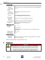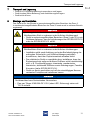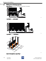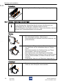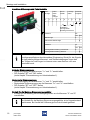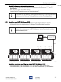
1
Betriebsanleitung
DE
Operating instructions
EN
Additional languages www.stahl-ex.com
DE EN
DE
EN
DE
EN
DE
EN
DE
EN
DE
EN
pac-Träger
pac-Carrier
DE
EN
DE
EN
Reihe 9195
Series 9195
DE
Betriebsanleitung
DE
Additional languages www.stahl-ex.com
DE
DE
DE
DE
DE
DE
DE
DE
DE
DE
DE
DE
DE
DE
DE
DE
DE
DE
pac-Träger
DE
DE
DE
Reihe 9195
DE
DE
DE
DE
DE
Inhaltsverzeichnis
DE
1
1.1
1.2
1.3
1.4
2
2.1
2.2
2.3
3
3.1
3.2
3.3
4
4.1
4.2
5
6
7
8
8.1
8.2
8.3
9
9.1
10
10.1
10.2
10.3
11
11.1
11.2
11.3
11.4
12
13
DE
DE
DE
DE
DE
DE
DE
DE
DE
DE
DE
DE
DE
DE
DE
DE
DE
DE
DE
DE
DE
DE
DE
2
Allgemeine Angaben ...........................................................................................3
Hersteller .............................................................................................................3
Angaben zur Betriebsanleitung ...........................................................................3
Weitere Dokumente ............................................................................................3
Konformität zu Normen und Bestimmungen .......................................................3
Erläuterung der Symbole ....................................................................................4
Symbole in der Betriebsanleitung .......................................................................4
Warnhinweise .....................................................................................................4
Symbole am Gerät ..............................................................................................5
Sicherheitshinweise ............................................................................................5
Aufbewahrung der Betriebsanleitung ..................................................................5
Sichere Verwendung ...........................................................................................5
Umbauten und Änderungen ................................................................................6
Funktion und Geräteaufbau ................................................................................7
Funktion ..............................................................................................................7
Geräteaufbau ......................................................................................................8
Technische Daten ...............................................................................................9
Projektierung .....................................................................................................10
Transport und Lagerung ...................................................................................11
Montage und Installation ...................................................................................11
Maßangaben / Befestigungsmaße ....................................................................12
Montage / Demontage, Gebrauchslage ............................................................13
Installation .........................................................................................................15
Parametrierung und Inbetriebnahme ................................................................18
Parametrierungen .............................................................................................18
Betrieb ...............................................................................................................19
Betrieb ...............................................................................................................19
Anzeigen ...........................................................................................................19
Fehlerbeseitigung .............................................................................................19
Instandhaltung, Wartung, Reparatur .................................................................20
Instandhaltung ..................................................................................................20
Wartung ............................................................................................................20
Reparatur ..........................................................................................................21
Rücksendung ....................................................................................................22
Entsorgung ........................................................................................................22
Zubehör und Ersatzteile ...................................................................................22
pac-Träger
Reihe 9195
160799 / 9195601310
2015-07-20·BA00·III·de·00
Allgemeine Angaben
1
Allgemeine Angaben
1.1
Hersteller
1.2
1.3
1.4
DE
DE
DE
R. STAHL Schaltgeräte GmbH
Am Bahnhof 30
74638 Waldenburg
Germany
DE
Tel.:
Fax:
Internet:
E-Mail:
DE
DE
DE
DE
+49 7942 943-0
+49 7942 943-4333
www.stahl-ex.com
[email protected]
Angaben zur Betriebsanleitung
ID-Nr.:
Publikationsnummer:
Hardwareversion:
Softwareversion:
DE
DE
DE
DE
160799 / 9195601310
2015-07-20·BA00·III·de·05
n/a
n/a
DE
DE
DE
Die Originalbetriebsanleitung ist die englische Ausgabe.
Diese ist rechtsverbindlich in allen juristischen Angelegenheiten.
DE
Weitere Dokumente
DE
DE
DE
• Installationsanleitung Schaltschrank
• Datenblatt 9192, 9195, 9196
• FMEDA Report
• Engineering Guide
Weitere Sprachen, siehe www.stahl-ex.com.
DE
DE
DE
DE
Konformität zu Normen und Bestimmungen
DE
Siehe Zertifikate und EG-Konformitätserklärung: www.stahl-ex.com.
Das Gerät verfügt über eine IECEx-Zulassung. Siehe IECEx-Homepage:
http://iecex.iec.ch/
Weitere nationale Zertifikate stehen unter dem folgenden Link zum Download bereit:
http://www.r-stahl.com/downloads/certificates.html.
160799 / 9195601310
2015-07-20·BA00·III·de·05
pac-Träger
Reihe 9195
DE
3
Erläuterung der Symbole
DE
DE
2
Erläuterung der Symbole
DE
2.1
Symbole in der Betriebsanleitung
DE
Symbol
DE
Bedeutung
Tipps und Empfehlungen zum Gebrauch des Geräts
DE
DE
DE
DE
Gefahr allgemein
DE
DE
DE
Gefahr durch explosionsfähige Atmosphäre
DE
DE
DE
Gefahr durch spannungsführende Teile
DE
DE
DE
DE
2.2
DE
DE
DE
DE
DE
Warnhinweise
Warnhinweise unbedingt befolgen, um das konstruktive und durch den Betrieb bedingte
Risiko zu minimieren. Die Warnhinweise sind wie folgt aufgebaut:
• Signalwort: GEFAHR, WARNUNG, VORSICHT, HINWEIS
• Art und Quelle der Gefahr/des Schadens
• Folgen der Gefahr
• Ergreifen von Gegenmaßnahmen zum Vermeiden der Gefahr bzw. des Schadens
GEFAHR
DE
Gefahren für Personen
Nichtbeachtung der Anweisung führt zu schweren oder tödlichen
Verletzungen bei Personen.
WARNUNG
Gefahren für Personen
Nichtbeachtung der Anweisung kann zu schweren oder tödlichen
Verletzungen bei Personen führen.
VORSICHT
Gefahren für Personen
Nichtbeachtung der Anweisung kann zu leichten Verletzungen bei
Personen führen.
HINWEIS
Vermeidung von Sachschaden
Nichtbeachtung der Anweisung kann zu einem Sachschaden am Gerät und/oder
seiner Umgebung führen.
4
pac-Träger
Reihe 9195
160799 / 9195601310
2015-07-20·BA00·III·de·05
Sicherheitshinweise
2.3
DE
Symbole am Gerät
Symbol
DE
Bedeutung
CE-Kennzeichnung gemäß aktuell gültiger Richtlinie.
DE
DE
05594E00
02198E00
Stromkreis gemäß Kennzeichnung für explosionsgefährdete Bereiche
zertifiziert.
DE
Eingang
DE
DE
DE
15649E00
Ausgang
DE
15648E00
3
Sicherheitshinweise
3.1
Aufbewahrung der Betriebsanleitung
3.2
DE
DE
DE
DE
• Betriebsanleitung sorgfältig lesen.
• Betriebsanleitung am Einbauort des Geräts aufbewahren.
• Mitgeltende Dokumente und Betriebsanleitungen der anzuschließenden Geräte
beachten.
DE
DE
DE
DE
Sichere Verwendung
Vor der Montage
• Sicherheitshinweise in dieser Betriebsanleitung lesen und beachten!
• Sicherstellen, dass der Inhalt dieser Betriebsanleitung vom zuständigen Personal voll
verstanden wurde.
• Gerät nur bestimmungsgemäß und nur für den zugelassenen Einsatzzweck
verwenden.
• Bei Betriebsbedingungen, die durch die technischen Daten des Geräts nicht
abgedeckt werden, unbedingt bei der R. STAHL Schaltgeräte GmbH rückfragen.
• Für die Projektierung das Dokument "Installationsanleitung Schaltschrank" beachten
(Download über www.stahl-ex.com, Produktdokumentation, Unterpunkt
"Projektierung").
• Für Schäden, die durch fehlerhaften oder unzulässigen Einsatz des Geräts sowie
durch Nichtbeachtung dieser Betriebsanleitung entstehen, besteht keine Haftung.
Bei Montage und Installation
• Nationale Montage- und Errichtungsvorschriften beachten (z.B. IEC/EN 60079-14).
• Nationale Sicherheits- und Unfallverhütungsvorschriften beachten.
• Bei Installation und im Betrieb die Angaben (Kennwerte und Bemessungsbetriebsbedingungen) auf Typ- und Datenschildern sowie die Hinweisschilder am Gerät
beachten.
• Vor Installation sicherstellen, dass das Gerät unbeschädigt ist.
• Stromkreise der Zündschutzart "Ex i", die mit Stromkreisen anderer Zündschutzarten
betrieben wurden, dürfen danach nicht mehr als Stromkreise der Zündschutzart "Ex i"
betrieben werden.
160799 / 9195601310
2015-07-20·BA00·III·de·05
pac-Träger
Reihe 9195
5
DE
DE
DE
DE
DE
DE
DE
DE
Sicherheitshinweise
DE
Wartung, Reparatur, Inbetriebnahme
• Vor Inbetriebnahme sicherstellen, dass das Gerät unbeschädigt ist.
• Arbeiten am Gerät, wie Installation, Instandhaltung, Wartung, Störungsbeseitigung,
nur von dazu befugtem und entsprechend geschultem Personal durchführen lassen.
• Nur Wartungsarbeiten bzw. Reparaturen durchführen, die in dieser Betriebsanleitung
beschrieben sind.
• Das Gerät enthält Bauteile, die durch elektrostatische Entladung beschädigt werden
können. Vor Arbeiten am Gerät Körper an geerdeten Metallteilen entladen bzw.
ein ESD-Ableitband anlegen.
• Sicherstellen, dass die Bemessungsspannung beim Anschluss der Signalstromkreise
um nicht mehr als 40 % überschritten wird.
• Die auswechselbaren Sicherungen des Geräts dürfen nur außerhalb der Zone 2, 22
oder im spannungslosen Zustand gewechselt werden. Der Betrieb ist nur mit
vollständig eingeschraubter Sicherungsabdeckung zulässig.
DE
DE
DE
DE
DE
DE
DE
DE
DE
DE
DE
DE
3.3
Umbauten und Änderungen
GEFAHR
DE
DE
Explosionsgefahr durch Umbauten und Änderungen am Gerät!
Nichtbeachten führt zu schweren oder tödlichen Verletzungen.
• Gerät nicht umbauen oder verändern.
DE
DE
DE
Für Schäden, die durch Umbauten und Änderungen entstehen, besteht keine
Haftung und keine Gewährleistung.
DE
DE
DE
DE
DE
DE
DE
6
pac-Träger
Reihe 9195
160799 / 9195601310
2015-07-20·BA00·III·de·05
Funktion und Geräteaufbau
4
DE
Funktion und Geräteaufbau
DE
GEFAHR
DE
Explosionsgefahr durch zweckentfremdete Verwendung!
Nichtbeachten führt zu schweren oder tödlichen Verletzungen.
• Gerät nur entsprechend den in dieser Betriebsanleitung
festgelegten Betriebsbedingungen verwenden.
• Gerät nur entsprechend dem in dieser Betriebsanleitung
genannten Einsatzzweck verwenden.
4.1
DE
DE
DE
DE
DE
DE
Funktion
DE
Einsatzbereich
Der pac-Träger 9195 dient zur einfachen und komfortablen Integration von
ISpac-Trennstufen in Automatisierungssysteme über vorkonfektionierte Systemkabel
und systemspezifische Anschlussleiterplatten. Er ist für den Einsatz in der Zone 2, 22
oder außerhalb explosionsgefährdeter Bereiche vorgesehen.
DE
DE
DE
DE
Arbeitsweise
Der pac-Träger 9195 lässt sich einfach an HART-Management-Systeme anschließen.
Es existiert eine feste Zuordnung zwischen I/O-Modulen und pac-Träger. Der pac-Träger
kann 8 oder 16 Trennstufen mit bis zu 32 Kanälen aufnehmen und dabei auch
gleichzeitig Ex i- und nicht-Ex i-Signale weiterleiten.
Der pac-Träger besitzt eine redundante Hilfsversorgung und eine auswechselbare
Sicherung.
Die HART-Kommunikation zwischen Feldgerät und Managementsystem ist über den
pac-Träger möglich.
DE
DE
DE
DE
DE
DE
DE
DE
DE
DE
DE
160799 / 9195601310
2015-07-20·BA00·III·de·05
pac-Träger
Reihe 9195
7
Funktion und Geräteaufbau
DE
DE
4.2
Geräteaufbau
DE
DE
DE
DE
DE
DE
DE
DE
DE
DE
DE
11871E00
DE
DE
DE
DE
DE
DE
DE
DE
DE
DE
DE
DE
#
Gerätelement
Beschreibung
1
pac-Träger für 16 Module (32 Kanäle)
Aufstecken von bis zu 16 Modulen auf jeweils einen
pac-Träger
2
Beschriftungsfeld
Beschriftung der Module
3
Auswerf-Mechanismus
(mit Schraubendreher)
Klemmung der einzelnen Module
4
2x Fehlermeldekontakte
PF (5/6): Power Fail,
LF (7/8): Leitungsfehler-Meldekontakte
5
Sicherung pac-Träger
Auswechselbare Sicherungen
6
2x LED grün, "PWR1", "PWR2",
je eine LED pro Hilfsenergieanschluss
Betriebsanzeige Hilfsenergieversorgung
(primär oder redundant)
7
2x Hilfsenergieanschluss (24 V)
PWR1 (1/2): primärer Hilfsenergieanschluss
PWR2 (3/4): redundanter Hilfsenergieanschluss
(Verwendung optional)
8
2x DIP-Schalter
SP: Redundante Hilfsenergieversorgung
aktiviert / deaktiviert
LFS: Leitungsfehlermeldung aktiviert /
deaktiviert
Aktivierung bzw. Deaktivierung der redundanten
Hilfsenergie bzw. des Fehlerkontaktes
(siehe Kapitel "DIP-Schalter am pac-Träger")
9
Systemspezifische Stecker
Verschiedene Stecker, je nach Variante
10
Signalverdoppler oder / und Anschluss
HART-Multiplexer
14-polige Anschlussbuchse
11
Integrierter pac-Bus
Zuführung Hilfsenergie an Module, Kontakte für
Leitungsfehler-Meldung
12
Rastmechanismus
Rasthebel für Klemmung der Module auf
pac-Träger
13
Modul
Modul mit beliebigem Signalmix steckbar
Spezifische pac-Träger siehe Engineering Guide.
8
pac-Träger
Reihe 9195
160799 / 9195601310
2015-07-20·BA00·III·de·05
Technische Daten
5
DE
Technische Daten
Kennzeichnung
Typbezeichnung
CE-Kennzeichnung
DE
DE
9195/...-...-...
C0158
DE
DE
Explosionsschutz
DE
Global (IECEx)
DE
Gas
IECEx BVS 10.0042X
DE
Ex nA nC IIC T4 Gc
DE
Europa (ATEX)
Gas
DE
BVS 03 ATEX E 213 X
DE
E II 3 G Ex nA nC IIC T4 Gc
DE
Bescheinigungen und Zertifikate
Bescheinigungen
IECEx, ATEX, Brasilien (INMETRO), Kanada (cFM), Kasachstan (TR),
Russland (TR), Ukraine (TR), USA (FM), Weißrussland (TR)
Schiffszertifikate
DNV
DE
DE
DE
Funktionale Sicherheit (IEC 61508)
Prüfbericht
Stahl 04/04-03 R002
max. SIL
3
Safe Failure
Fraction SFF
74 ... 95 %
PFDAVG bei T[Proof]
DE
DE
DE
DE
DE
T[Proof]
PFDAVG
1 Jahr
3,89 x 10⁶
5 Jahre
1,12 x 10⁻⁵
10 Jahre
2,04 x 10
DE
DE
DE
-5
DE
Weitere Parameter
Installation
in Zone 2, Div. 2 und im sicheren Bereich
Weitere Angaben
siehe jeweilige Bescheinigung und Betriebsanleitung
DE
Technische Daten
Elektrische Daten
Hilfsenergie
Nennspannung
UN
24 V DC
Spannungsbereich
18 ... 31,2 V
Restwelligkeit
( 3,6 VSS
ja, diodenentkoppelt
Redundante
Einspeisung
Betriebsanzeige
2 LED grün "PWR1"; "PWR2"
Sicherung
2 x TR5; T 2,0 A; auswechselbar, für primäre und redundante Versorgung
Verpolschutz
ja
160799 / 9195601310
2015-07-20·BA00·III·de·05
pac-Träger
Reihe 9195
9
Projektierung
DE
Technische Daten
DE
Feldgeräte
DE
DE
DE
Anschluss
an den Klemmen der Ex i Trennstufen (Spezifikation siehe Gerätedatenblätter)
Anzahl Kanäle
8, 16, 32
Automatisierungssysteme
DE
DE
Anschluss
Systemspezifische Stecker (Sub-D, Elco, usw.)
DE
Anzahl Kanäle
bis zu 32
DE
HART-Schnittstelle
Anschluss
DE
DE
- über Anschluss Automatisierungssysteme
- über HART-Multiplexer 9192 (nur bei 9195/..H-...-...)
Fehlermeldung
DE
Hilfsenergieausfall PF
Kontakt (35 V / 100 mA), im Gutzustand geschlossen
DE
DE
Leitungsfehler LF
Kontakt (35 V / 100 mA), im Gutzustand geschlossen
Elektromagnetische
Verträglichkeit
DE
DE
Geprüft nach folgenden Normen und Vorschriften:
EN 61326-1 Einsatz im industriellen Bereich;
NAMUR NE 21
Umgebungstemperatur
DE
Umgebungstemperatur
DE
DE
-20 ... +70 °C
Montage beliebig
DE
Spezifikation der Ex i Trennstufen beachten, siehe "Installationsanleitung
Schaltschrank"
DE
DE
Lagertemperatur
-40 ... +80 °C
DE
Relative Feuchte
(keine Betauung)
( 95 %
DE
Montage / Installation
DE
Einbaubedingungen
Montageart
auf Hutschiene (NS35/15, NS35/7,5) oder Montageplatte (4 x Schraube M6)
Einbaulage
senkrecht oder waagrecht
Weitere technische Daten, siehe www.stahl-ex.com.
6
Projektierung
GEFAHR
Explosionsgefahr durch zu hohe Temperatur im Schaltschrank!
Nichtbeachten führt zu schweren oder tödlichen Verletzungen!
• Schaltschrank so aufbauen und einrichten, dass er immer
innerhalb des zulässigen Temperaturbereichs betrieben wird.
• "Installationsanleitung Schaltschrank" sorgfältig beachten.
10
pac-Träger
Reihe 9195
160799 / 9195601310
2015-07-20·BA00·III·de·05
Transport und Lagerung
7
DE
Transport und Lagerung
DE
• Gerät nur in Originalverpackung transportieren und lagern.
• Gerät trocken (keine Betauung) und erschütterungsfrei lagern.
• Gerät nicht stürzen.
DE
DE
DE
8
Montage und Installation
DE
Das Gerät ist für den Einsatz in gasexplosionsgefährdeten Bereichen der Zone 2,
in staubexplosionsgefährdeten Bereichen der Zone 22 sowie auch im sicheren Bereich
zugelassen.
GEFAHR
Explosionsgefahr bei Installation ohne zugelassenes Feldgehäuse!
Nichtbeachten führt zu schweren oder tödlichen Verletzungen!
• Gerät in explosionsgefährdeten Bereichen (Zone 2 oder 22) in ein
Gehäuse einbauen, das die Anforderungen der IEC/EN 60079-15
oder der IEC/EN 60079-31 erfüllt.
Explosionsgefahr durch falsche Installation des Geräts!
Nichtbeachten führt zu schweren oder tödlichen Verletzungen.
• Installation strikt nach Anleitung und unter Berücksichtigung der
nationalen Sicherheits- und Unfallverhütungsvorschriften
durchführen, damit der Explosionsschutz erhalten bleibt.
• Das elektrische Gerät so auswählen bzw. installieren, dass der
Explosionsschutz aufgrund äußerer Einflüsse nicht beeinträchtigt
wird, z. B. Druckbedingungen, chemische, mechanische,
thermische, elektrische Einflüsse sowie Schwingungen, Feuchte,
Korrosion (siehe IEC/EN 60079-14).
• Gerät nur durch geschultes und mit den einschlägigen Normen
vertrautes Fachpersonal installieren lassen.
HINWEIS
Geräteausfall oder -schaden durch ungesicherte Bauelemente!
Nichtbeachten kann Sachschaden verursachen.
• Den pac-Träger 9195/08A-FX1-01U (ohne LED, Sicherung) extern mit
T2,0 A sichern.
pac-Träger
Reihe 9195
DE
DE
DE
DE
DE
DE
DE
DE
GEFAHR
160799 / 9195601310
2015-07-20·BA00·III·de·05
DE
11
DE
DE
DE
DE
DE
DE
DE
DE
DE
DE
Montage und Installation
DE
DE
8.1
DE
Maßangaben / Befestigungsmaße
Maßzeichnungen (alle Maße in mm [Zoll]) – Änderungen vorbehalten
DE
155 [6,10]
DE
DE
130 [5,12]
DE
DE
DE
DE
149 [5,87]
130 [5,12]
150 [5,91]
DE
09826E00
DE
Typ 9195/08.-...-..., 8 Steckplätze
DE
DE
DE
155 [6,10]
DE
DE
130 [5,12]
DE
DE
DE
DE
149 [5,87]
DE
130 [5,12]
150 [5,91]
292 [11,50]
DE
09854E00
Typ 9195/16.-...-..., 16 Steckplätze
DE
DE
,7
18
,6
10
m
m
/0
2
.4
m
m
/0
4
.7
"
64,6
m
2.54 m
"
m
m
9 "
2, .84
2
1 4
6 mm
0.24
"
m
m
9 "
2, .84
2
1 4
"
m
m
9 "
2, 4
12 4.8
6
,
10
m
m
/0
2
.4
"
m
4
m
.7
9 "
2, 4
/0
12 4.8
m
m
,7
18
"
15632E00
Maße für Montagelöcher am pac-Träger
12
pac-Träger
Reihe 9195
160799 / 9195601310
2015-07-20·BA00·III·de·05
Montage und Installation
8.2
DE
Montage / Demontage, Gebrauchslage
DE
Die Gebrauchslage ist abhängig von den eingesetzten Ex i Trennstufen
(siehe jeweilige Betriebsanleitung).
DE
DE
8.2.1 Montage / Demontage auf Hutschiene
Montage
DE
DE
• pac-Träger auf Hutschiene ansetzen und so
aufschwenken, dass der Fußriegel bzw. die beiden
Fußriegel einrasten.
DE
DE
DE
DE
DE
DE
DE
08032E00
DE
DE
Demontage
DE
• In umgekehrter Reihenfolge zur Montage vorgehen.
DE
DE
DE
DE
DE
15634E00
DE
DE
DE
DE
15633E00
8.2.2 Montage / Demontage auf Montageplatte
Montage
• pac-Träger über vorhandene Montagelöcher mit
mindestens 4 Schrauben M5 bzw. 6 Schrauben M5 auf
Montageplatte festschrauben.
08037E00
160799 / 9195601310
2015-07-20·BA00·III·de·05
pac-Träger
Reihe 9195
13
Montage und Installation
DE
Demontage
DE
• In umgekehrter Reihenfolge zur Montage vorgehen.
DE
DE
DE
DE
DE
DE
DE
DE
08037E00
8.2.3 Montage / Demontage auf pac-Träger
DE
Vor der Montage des Trennstufen-Moduls müssen alle Klemmen und
Abdeckungen auf der Seite des Fußriegels entfernt werden.
Beim Aufschwenken des Geräts auf den pac-Träger darauf achten, dass das
Gehäuse des Trennstufen-Moduls nicht verkantet.
DE
DE
DE
DE
DE
Montage
DE
• Schwarze und grüne Klemmen entfernen.
• Bei einkanaligen Geräten: Abdeckung im
Klemmenschacht 2 entfernen (zwischen schwarzer und
grüner Klemme).
DE
DE
DE
DE
DE
DE
12613E00
DE
DE
15569E00
• Gerät auf pac-Träger aufsetzen. Dabei die Aussparung
des Gehäuses auf die Außenkante des pac-Trägers
setzen.
• Beim Aufschwenken des Geräts auf den pac-Träger
darauf achten, dass es nicht verkantet.
• Das Gerät bis zum roten Rasthebel einschwenken.
• Roten Rasthebel durch schrägen Druck mit dem Daumen
auf den Hebel schließen, bis dieser hörbar am Gerät
einrastet.
• Sicherstellen, dass der rote Rasthebel eingerastet ist.
Demontage
• Rasthebel mit einem Schraubendreher ausschwenken.
• Gerät aus dem Steckplatz ausschwenken.
15574E00
14
pac-Träger
Reihe 9195
160799 / 9195601310
2015-07-20·BA00·III·de·05
Montage und Installation
8.3
DE
Installation
DE
GEFAHR
Explosionsgefahr durch spannungsführende Teile!
Nichtbeachten führt zu schweren oder tödlichen Verletzungen!
• In explosionsgefährdeten Bereichen KEINE Anschlussarbeiten
am Gerät (z.B. Leitungen an Anschlussklemmen durchführen.
• In explosionsgefährdeten Bereichen KEINE Anschlussklemmen
aufstecken oder abziehen.
• Vor Arbeiten am Gerät alle Anschlüsse und die
Hilfsenergieversorgung spannungsfrei schalten.
Bei Betrieb unter erschwerten Bedingungen wie insbesondere auf Schiffen
sind zusätzliche Maßnahmen zur korrekten Installation je nach Einsatzort zu
treffen. Weitere Informationen und Anweisungen hierzu erhalten Sie gerne
auf Anfrage von Ihrem zuständigen Vertriebskontakt.
DE
DE
DE
DE
DE
DE
DE
DE
DE
DE
DE
DE
DE
DE
8.3.1 Elektrische Anschlüsse
DE
GEFAHR
DE
Explosionsgefahr durch zu hohe Spannung!
Nichtbeachten führt zu schweren oder tödlichen Verletzungen.
• Gerät nur an Betriebsmittel mit interner Spannung
Um: max. 253 V AC / 50 Hz anschließen.
• Gerät nur an eigensichere Klemmen anschließen.
DE
DE
DE
DE
DE
GEFAHR
Explosionsgefahr durch falsche sicherheitstechnische Werte des
Geräts oder angeschlossener Feldgeräte!
Nichtbeachten führt zu schweren oder tödlichen Verletzungen.
• Sicherheitstechnische Werte des Geräts und angeschlossener
Feldgeräte entsprechend der nationalen Installationsvorschriften
prüfen.
HINWEIS
Geräteausfall durch elektrostatisch überladene Bauelemente!
Nichtbeachten kann Sachschaden verursachen!
• Vor Arbeiten am Gerät körpereigene Spannung an geerdeten Metallteilen
entladen oder ein ESD-Ableitband anlegen.
160799 / 9195601310
2015-07-20·BA00·III·de·05
pac-Träger
Reihe 9195
15
DE
DE
Montage und Installation
DE
Anschluss Hilfsenergie und Fehlerkontakte
DE
1
DE
DE
DE
DE
DE
Hilfsenergie
redundante
Hilfsenergie
Stromausfall
Leitungs- Potentialfehler
ausgleich
1
2
3
4
5
7
+
-
+
-
6
8
9
15271E00
DE
17250E00
10
15271E00
17250E00
Kontakte in
störungsfreien
Betrieb geschlossen
DE
DE
DE
15635E00
2
Funktion
SP
ON
DE
Hilfsenergie
DE
X
redundante Hilfsenergie
DE
DE
X
Funktion
DE
OFF
LF
ON
DE
Leitungsfehlermeldung unterdrückt
DE
Leitungsfehlermeldung aktiviert
OFF
X
X
DE
Die trägerspezifischen Anschlusspläne (Engineering Guide) für die Signale
mit den jeweils gültigen Klemmen- und Steckerbelegungen liegen den
pac-Trägern bei oder liegen im Internet unter www.stahl-ex.com zum
Download bereit.
DE
DE
DE
DE
DE
Einfache Stromversorgung
• Stromversorgung an die Klemmen "1+" und "2-" anschließen.
• DIP-Schalter "SP" auf "ON" stellen
(siehe Kapitel "Parametrierung und Inbetriebnahme").
DE
Redundante Stromversorgung
• Stromversorgung an die Klemmen "1+" und "2-" anschließen.
• Redundante Stromversorgung an die Klemmen "3+" und "4-" anschließen.
• DIP-Schalter "SP" auf "OFF" stellen
(siehe Kapitel "Parametrierung und Inbetriebnahme").
Kontakt für die Meldung Stromversorgungsfehler
• Kontakt für die Meldung Stromversorgungsfehler an die Klemmen "5" und "6"
anschließen.
Der Kontakt für die Meldung Stromversorgungsfehler ist im Normalzustand
geschlossen. Bei Ausfall der Hilfsenergie wird der Kontakt geöffnet.
16
pac-Träger
Reihe 9195
160799 / 9195601310
2015-07-20·BA00·III·de·05
Montage und Installation
DE
Kontakt für Meldung Leitungsfehlererkennung
• Kontakt für die Meldung Leitungsfehlererkennung an die Klemmen "7 " und "8 "
anschließen.
• DIP-Schalter "LFS" auf "OFF" stellen
(siehe Kapitel "Parametrierung und Inbetriebnahme").
DE
DE
DE
DE
DE
Der Kontakt für die Meldung Leitungsfehlererkennung ist im Normalzustand
geschlossen. Im Fall eines Leitungsfehlers wird der Kontakt geöffnet.
DE
DE
DE
DE
8.3.2 Anschluss von HART-Multiplexer 9192
Der pac-Träger kann an dem HART-Multiplexer 9192 angeschlossen werden.
• Verbindung über die mitgelieferten 14-poligen Flachbandkabel herstellen.
DE
DE
DE
DE
Weitere Informationen zum HART-Multiplexer siehe Datenblatt und/oder
Betriebsanleitung 9192.
DE
DE
DE
PC
DE
9185/..
RS 232
1
RS 485/RS 232
DE
DE
DE
RS 485
7
4
7
1
8
1
2
5
3
6
4
7
1
8
1
3
2
4
3
5
4
6
5
4
7
1
8
8
7
1
8
25 26 27 28 29 30 31 32
2
1
3
2
4
3
5
4
6
5
2
5
3
6
8
7
1
8
17 18 19 20 21 22 23 24
2
1
DE
4
7
1
8
9195/12A-SI1-01B5
7
6
1
3
2
4
3
5
4
6
5
9195/12A-SI1-01B5
7
6
8
7
1
8
9 10 11 12 13 14 15 16
2
3
4
5
6
7
8
3
1
2
3
4
5
6
7
8
1
2
3
4
5
6
7
8
15702E00
Anschluss von einem pac-Träger an einen HART-Multiplexer 9192
• Flachbandkabel (2) an Schnittstelle "X1" (4) am pac-Träger anschließen.
• Flachbandkabel (2) an Schnittstelle "X1" am HART-Multiplexer (3) anschließen.
160799 / 9195601310
2015-07-20·BA00·III·de·05
pac-Träger
Reihe 9195
DE
DE
2
25
T2A
9195/12A-SI1-01B5
7
6
3
6
4
25
T2A
T2A
9195/12A-SI1-01B5
2
2
5
25
25
1
1
LFS
SP
T2A
3
6
5
T2A
2
5
LFS
SP
T2A
T2A
1
LFS
SP
T2A
LFS
SP
6
DE
17
Parametrierung und Inbetriebnahme
DE
Anschluss von zwei pac-Trägern an einen HART-Multiplexer 9192
• Flachbandkabel (2) an Schnittstelle "X1" (4) am ersten pac-Träger anschließen.
• Flachbandkabel (2) an Schnittstelle "X1" am HART-Multiplexer (3) anschließen.
• Flachbandkabel (6) an Schnittstelle "X2" (5) am ersten pac-Träger anschließen.
• Flachbandkabel (6) an Schnittstelle "X1" (7) am zweiten pac-Träger anschließen.
DE
DE
DE
DE
DE
Anschluss von weiteren pac-Trägern an einen HART-Multiplexer
Nach Anschluss der pac-Träger kann über einen Feldbus-Trennübertrager 9185/.. (1)
eine Verbindung zwischen dem HART-Multiplexer 9192 (RS-485-Schnittstelle) und
einem PC (RS-232-Schnittstelle) hergestellt werden (siehe obige Zeichnung).
DE
DE
DE
DE
DE
9
Parametrierung und Inbetriebnahme
GEFAHR
DE
Explosionsgefahr durch fehlerhafte Installation!
Nichtbeachten führt zu schweren oder tödlichen Verletzungen.
• Gerät vor der Inbetriebnahme auf korrekte Installation prüfen.
• Nationale Bestimmungen einhalten.
DE
DE
DE
DE
DE
Vor Inbetriebnahme Folgendes sicherstellen:
• Vorschriftsmäßige Installation des Gerätes.
• Richtiger Anschluss der Kabel.
• Keine Schäden an Gerät und an Anschlusskabeln.
• Fester Sitz der Schrauben an den Klemmen.
Richtiges Anzugsdrehmoment: 0,5 ... 0,6 Nm.
DE
DE
DE
DE
Parametrierungen
DE
Leitungsfehlermeldung LFS
Einspeisung SP
unterdrückt
aktiviert *)
einfach
redundant *)
LFS
SP
9.1.1 DIP-Schalter am pac-Träger
LFS
SP
DE
9.1
LFS
SP
DE
LFS
SP
DE
OFF
ON
OFF
OFF
OFF
ON
ON
ON
08034E00
08033E00
08036E00
08035E00
*) Standardeinstellung bei Auslieferung
Die Änderung der DIP-Schalter-Einstellungen ist im Betrieb auch in der
Zone 2 und 22 zulässig.
18
pac-Träger
Reihe 9195
160799 / 9195601310
2015-07-20·BA00·III·de·05
Betrieb
10
DE
Betrieb
DE
DE
10.1 Betrieb
Nach erfolgreicher Installation und Parametrierung Gerät folgendermaßen in Betrieb
nehmen:
• Hilfsenergieversorgung des Geräts einschalten.
DE
DE
DE
10.2 Anzeigen
DE
Entsprechende LEDs am Gerät zeigen den Betriebszustand des Geräts und die
Leitungsfehlerzustände an (siehe auch Kapitel "Funktion und Geräteaufbau").
DE
DE
LED
Farbe
LED "EIN"
LED "AUS"
LED "PWR1"
grün
Hilfsenergie vorhanden
Hilfsenergie ausgefallen
LED "PWR2"
grün
redundante Hilfsenergie vorhanden
redundante Hilfsenergie ausgefallen
DE
10.3 Fehlerbeseitigung
Fehler
Kein Ausgangssignal
Fehlerursache
•
•
•
•
•
Hilfsenergie ausgefallen
Gerätesicherung defekt
Hilfsenergieversorgung
verpolt
Leitungsfehlermeldung
deaktiviert.
Fehlerkontakte nicht
korrekt verdrahtet.
DE
Fehlerbehebung
• Polarität der Hilfsenergieversorgung
kontrollieren.
• Verdrahtung der
Hilfsenergieversorgung kontrollieren.
• Sicherungswechsel*) bei Betrieb in
Zone 2 nur im spannungslosen
Zustand!
• Der Betrieb ist nur mit vollständig
eingeschraubter
Sicherungsabdeckung zulässig.
•
•
Leitungsfehlermeldung über
DIP-Schalter "LFS" aktivieren.
Verdrahtung der Fehlerkontakte
prüfen.
DE
DE
DE
DE
DE
DE
DE
DE
DE
Wenn sich der Fehler mit den genannten Vorgehensweisen nicht beheben lässt:
• An R. STAHL Schaltgeräte GmbH wenden.
Zur schnellen Bearbeitung folgende Angaben bereithalten:
• Typ und Seriennummer des Geräts
• Kaufdaten
• Fehlerbeschreibung
• Einsatzzweck (insbesondere Eingangs-/Ausgangsbeschaltung)
pac-Träger
Reihe 9195
DE
DE
*) Sicherungswechsel, siehe Kapitel "Sicherungswechsel"
160799 / 9195601310
2015-07-20·BA00·III·de·05
DE
DE
Bei der Fehlerbeseitigung folgenden Fehlersuchplan beachten:
LED "PWR1" und/oder
"PWR2" erloschen
DE
19
Instandhaltung, Wartung, Reparatur
DE
DE
11
Instandhaltung, Wartung, Reparatur
VORSICHT
DE
Stromschlaggefahr bzw. Fehlfunktion des Geräts durch unbefugte
Arbeiten!
Nichtbeachten kann zu leichten Verletzungen führen!
• Vor Arbeiten am Gerät Spannung abschalten.
• Arbeiten am Gerät ausschließlich von dazu autorisierter und
entsprechend geschulter Elektro-Fachkraft ausführen lassen.
DE
DE
DE
DE
DE
DE
DE
11.1 Instandhaltung
• Art und Umfang der Prüfungen den entsprechenden nationalen Vorschriften
entnehmen.
• Prüfungsintervalle an Betriebsbedingungen anpassen.
DE
DE
DE
Bei der Instandhaltung des Geräts mindestens folgende Punkte prüfen:
• fester Sitz der untergeklemmten Leitungen,
• Rissbildung und andere sichtbare Schäden am Gerätegehäuse und / oder
Schutzgehäuse,
• Einhaltung der zulässigen Umgebungstemperaturen,
• bestimmungsgemäße Funktion.
DE
DE
DE
DE
DE
DE
11.2 Wartung
Das Gerät benötigt keine regelmäßige Wartung.
DE
DE
DE
Die geltenden nationalen Bestimmungen im Einsatzland beachten.
DE
DE
DE
20
pac-Träger
Reihe 9195
160799 / 9195601310
2015-07-20·BA00·III·de·05
Instandhaltung, Wartung, Reparatur
DE
11.2.1 Sicherungswechsel
Das Gerät ist mit einer Sicherung vor Überspannungen geschützt.
Falls die Sicherung defekt sein sollte, kann diese leicht ausgetauscht werden.
DE
DE
DE
GEFAHR
Explosionsgefahr durch freiliegende Sicherung!
Nichtbeachten führt zu schweren oder tödlichen Verletzungen.
• Vor dem Wechsel der Sicherung sicherstellen, dass das Gerät
spannungsfrei ist. Eine Sicherung unter Spannung nur außerhalb
des explosionsgefährdeten Bereich wechseln.
• Nach dem Wechsel der Sicherung sicherstellen, dass die
Sicherungsabdeckung vollständig eingeschraubt ist.
15629E00
• Weiße Kreuzschlitzschraube so weit lösen, dass sich die
Sicherungsabdeckung drehen lässt.
• Die Sicherungsabdeckung horizontal so wegdrehen,
dass die Sicherung frei liegt.
• Die Sicherung mit Daumen und Zeigefinger greifen und
aus dem Sicherungssockel ziehen. Dabei darauf achten,
dass der Sicherungssockel nicht beschädigt wird.
• Neue Sicherung gleichen Typs in den Sicherungssockel
stecken und Sicherungsabdeckung wieder über die
Sicherung drehen.
• Abschließend Sicherungsabdeckung wieder
festschrauben.
DE
DE
DE
DE
DE
DE
DE
DE
DE
DE
DE
DE
DE
DE
DE
DE
DE
DE
11.3 Reparatur
DE
GEFAHR
DE
Explosionsgefahr durch unsachgemäße Reparatur!
Nichtbeachten führt zu schweren oder tödlichen Verletzungen.
• Reparaturen an den Geräten ausschließlich durch
R. STAHL Schaltgeräte GmbH ausführen lassen.
160799 / 9195601310
2015-07-20·BA00·III·de·05
pac-Träger
Reihe 9195
DE
21
Entsorgung
DE
DE
11.4 Rücksendung
Für die Rücksendung im Reparatur- bzw. Servicefall das Formular "Serviceschein"
verwenden. Auf der Internetseite "www.stahl-ex.com" im Menü "Downloads >
Kundenservice":
• Serviceschein herunterladen.
• Serviceschein ausfüllen.
• Gerät zusammen mit dem Serviceschein in der Originalverpackung an die
R. STAHL Schaltgeräte GmbH senden.
DE
DE
DE
DE
DE
DE
DE
12
Entsorgung
13
Zubehör und Ersatzteile
DE
DE
DE
DE
• Nationale und lokal gültige Vorschriften und gesetzliche Bestimmungen zur
Entsorgung beachten.
• Materialien getrennt dem Recycling zuführen.
• Umweltgerechte Entsorgung aller Bauteile gemäß den gesetzlichen Bestimmungen
sicherstellen.
DE
DE
DE
HINWEIS
DE
Fehlfunktion oder Geräteschaden durch den Einsatz nicht originaler Bauteile.
Nichtbeachten kann Sachschaden verursachen!
• Nur Original-Zubehör und Original-Ersatzteile der
R. STAHL Schaltgeräte GmbH verwenden.
DE
DE
DE
DE
Zubehör und Ersatzteile, siehe Datenblatt auf Homepage www.stahl-ex.com.
DE
DE
DE
DE
22
pac-Träger
Reihe 9195
160799 / 9195601310
2015-07-20·BA00·III·de·05
Operating instructions
EN
Additional languages www.stahl-ex.com
EN
EN
EN
EN
EN
EN
EN
EN
EN
EN
EN
EN
EN
EN
EN
EN
EN
EN
pac-Carrier
EN
EN
EN
Series 9195
EN
EN
EN
EN
EN
Contents
EN
1
1.1
1.2
1.3
1.4
2
2.1
2.2
2.3
3
3.1
3.2
3.3
4
4.1
4.2
5
6
7
8
8.1
8.2
8.3
9
9.1
10
10.1
10.2
10.3
11
11.1
11.2
11.3
11.4
12
13
EN
EN
EN
EN
EN
EN
EN
EN
EN
EN
EN
EN
EN
EN
EN
EN
EN
EN
EN
EN
EN
EN
EN
2
General Information ............................................................................................3
Manufacturer .......................................................................................................3
Information Regarding the Operating Instructions ..............................................3
Further Documents .............................................................................................3
Conformity with Standards and Regulations .......................................................3
Explanation of the Symbols ................................................................................4
Symbols in these Operating Instructions ............................................................4
Warning Notes ....................................................................................................4
Symbols on the Device .......................................................................................5
Safety Notes .......................................................................................................5
Operating Instructions Storage ...........................................................................5
Safe Use .............................................................................................................5
Modifications and Alterations ..............................................................................6
Function and Device Design ...............................................................................7
Function ..............................................................................................................7
Device Design .....................................................................................................8
Technical Data ....................................................................................................9
Engineering .......................................................................................................10
Transport and Storage ......................................................................................11
Mounting and Installation ..................................................................................11
Dimensions / Fastening Dimensions .................................................................12
Mounting / Dismounting, Operating Position .....................................................13
Installation .........................................................................................................15
Parameterization and Commissioning ..............................................................18
Parameterizations .............................................................................................18
Operation ..........................................................................................................19
Operation ..........................................................................................................19
Indications .........................................................................................................19
Troubleshooting ................................................................................................19
Maintenance and Repair ...................................................................................20
Maintenance .....................................................................................................20
Maintenance .....................................................................................................20
Repair ...............................................................................................................21
Returning the Device ........................................................................................22
Disposal ............................................................................................................22
Accessories and Spare Parts ...........................................................................22
pac-Carrier
Series 9195
160799 / 9195601310
2015-07-20·BA00·III·en·00
General Information
1
General Information
1.1
Manufacturer
1.2
1.3
1.4
EN
EN
EN
R. STAHL Schaltgeräte GmbH
Am Bahnhof 30
74638 Waldenburg
Germany
EN
Phone:
Fax:
Internet:
E-Mail:
EN
EN
EN
EN
+49 7942 943-0
+49 7942 943-4333
www.stahl-ex.com
[email protected]
EN
EN
EN
Information Regarding the Operating Instructions
ID-No.:
Publication Code:
Hardware version:
Software version:
EN
160799 / 9195601310
2015-07-20·BA00·III·en·05
n/a
n/a
EN
EN
EN
The original instructions are the English edition.
They are legally binding in all legal affairs.
EN
Further Documents
EN
EN
EN
• Cabinet installation guide
• Data sheet 9192, 9195, 9196
• FMEDA report
• Engineering guide
For further languages, see www.stahl-ex.com.
EN
EN
EN
EN
Conformity with Standards and Regulations
EN
See certificates and EC Declaration of Conformity: www.stahl-ex.com.
The device has IECEx approval. See IECEx homepage: http://iecex.iec.ch/
Further national certificates can be downloaded via the following link:
http://www.r-stahl.com/downloads/certificates.html.
160799 / 9195601310
2015-07-20·BA00·III·en·05
pac-Carrier
Series 9195
EN
3
Explanation of the Symbols
EN
EN
2
Explanation of the Symbols
EN
2.1
Symbols in these Operating Instructions
EN
Symbol
EN
Meaning
Tips and recommendations on the use of the device
EN
EN
EN
EN
General danger
EN
EN
EN
Danger due to explosive atmosphere
EN
EN
EN
Danger due to energised parts
EN
EN
EN
EN
2.2
EN
EN
EN
EN
EN
Warning Notes
Warnings must be observed under all circumstances, in order to minimize the risk due to
construction and operation. The warning notes have the following structure:
• Signalling word: DANGER, WARNING, CAUTION, NOTICE
• Type and source of danger/damage
• Consequences of danger
• Taking countermeasures to avoid the danger or damage
DANGER
EN
Danger to persons
Non-compliance with the instruction results in severe or fatal injuries to
persons.
WARNING
Danger to persons
Non-compliance with the instruction can result in severe or fatal injuries
to persons.
CAUTION
Danger to persons
Non-compliance with the instruction can result in light injuries to
persons.
NOTICE
Avoiding material damage
Non-compliance with the instruction can result in material damage to the device
and / or its environment.
4
pac-Carrier
Series 9195
160799 / 9195601310
2015-07-20·BA00·III·en·05
Safety Notes
2.3
EN
Symbols on the Device
Symbol
EN
Meaning
CE marking according to the current applicable directive.
EN
EN
05594E00
EN
According to marking, electric circuit certified for hazardous areas.
EN
02198E00
Input
EN
EN
15649E00
Output
EN
15648E00
3
Safety Notes
3.1
Operating Instructions Storage
3.2
EN
EN
EN
EN
• Read the operating instructions carefully.
• Store the operating instructions at the mounting location of the device.
• Observe applicable documents and operating instructions of the devices to be
connected.
EN
EN
EN
EN
Safe Use
Before mounting
• Read and observe the safety notes in these operating instructions!
• Ensure that the contents of these operating instructions are fully understood by the
personnel in charge.
• Use the device in accordance with its intended and approved purpose only.
• Always consult with R. STAHL Schaltgeräte GmbH if using the device under operating
conditions which are not covered by the technical data.
• Observe the document "Cabinet installation guide" for engineering (download from
www.stahl-ex.com, product documentation, subitem "Engineering").
• We cannot be held liable for damage at the device caused by incorrect or unauthorized
use or non-compliance with these operating instructions.
For mounting and installation
• Observe national installation regulations (e.g. IEC/EN 60079-14).
• Observe national safety and accident prevention regulations.
• During installation and operation, observe the information (characteristic values and
rated operating conditions) on the rating, data and information plates located on the
device.
• Before installation, make sure that the device is not damaged.
• Electric circuits with type of protection "Ex i" operated with circuits with other types of
protection can no longer be operated as circuits with type of protection "Ex i" after that.
160799 / 9195601310
2015-07-20·BA00·III·en·05
pac-Carrier
Series 9195
5
EN
EN
EN
EN
EN
EN
EN
EN
Safety Notes
EN
Maintenance, repair, commissioning
• Before commissioning, make sure that the device is not damaged.
• Work on the device, such as installation, maintenance, overhaul, repair, may only be
carried out by appropriately authorised and trained personnel.
• Perform only maintenance work or repair described in these operating instructions.
• The device contains components that can be damaged by electrostatic discharge.
Before carrying out work on the device, the body must be discharged on earthed metal
parts or an ESD wrist strap must be put on.
• Ensure that the rated voltage is not exceeded by more than 40 % when connecting
the signal circuits.
• The interchangeable fuses of the device may only be replaced outside Zone 2, 22 or
in a de-energised state. The operation is permitted only if the protective cover is
screwed in correctly.
EN
EN
EN
EN
EN
EN
EN
EN
EN
EN
EN
3.3
Modifications and Alterations
EN
DANGER
EN
Explosion hazard due to modifications and alterations to the device!
Non-compliance results in severe or fatal injuries.
• Do not modify or alter the device.
EN
EN
EN
No liability or warranty for damage resulting from modifications and
alterations.
EN
EN
EN
EN
EN
EN
EN
EN
6
pac-Carrier
Series 9195
160799 / 9195601310
2015-07-20·BA00·III·en·05
Function and Device Design
4
EN
Function and Device Design
EN
DANGER
EN
Explosion hazard due to improper use!
Non-compliance results in severe or fatal injuries.
• Use the device only in accordance with the operating conditions
described in these operating instructions.
• Use the device only for the intended purpose specified in these
operating instructions.
4.1
EN
EN
EN
EN
EN
EN
Function
Application range
The pac-Carrier 9195 is used for easy and convenient integration of the ISpac isolators
in the automation systems using prefabricated system cables and system specific PCB
termination boards. The device is intended for use in Zones 2, 22 or outside of hazardous
areas.
Mode of operation
The pac-Carrier 9195 is easily connected to HART management systems.
The assignment between I/O modules and the pac-Carrier is fixed. The pac-Carrier
can accommodate 8 or 16 isolators of up to 32 channels, while being able to transmit
simultaneously Ex i- and non-Ex i signals.
The pac-Carrier is provided with a redundant auxiliary power supply and an
interchangeable fuse.
HART communication between field device and management system is possible via the
pac-Carrier.
EN
EN
EN
EN
EN
EN
EN
EN
EN
EN
EN
EN
EN
EN
EN
EN
160799 / 9195601310
2015-07-20·BA00·III·en·05
pac-Carrier
Series 9195
7
Function and Device Design
EN
EN
4.2
Device Design
EN
EN
EN
EN
EN
EN
EN
EN
EN
EN
EN
11871E00
EN
#
Device component
Description
1
pac-Carrier for 16 modules (32 channels)
Connection of up to 16 modules to each
pac-Carrier
2
Labelling field
Labelling the modules
3
Ejection mechanism (with screwdriver)
Clamping of the individual modules
4
2 fault message contacts
EN
PF (5/6): Power Fail,
LF (7/8): line fault signalling contacts
5
Fuse pac-Carrier
Interchangeable fuses
EN
6
2 green LEDs "PWR1", "PWR2",
one LED for each auxiliary power
connection
Operation indication of auxiliary power supply
(primary or redundant)
7
2 auxiliary power connections (24 V)
PWR1 (1/2): primary auxiliary power connection
PWR2 (3/4): redundant auxiliary power connection
(use optional)
8
2 DIP switches
SP: redundant auxiliary power supply
activated / deactivated
LFS: Line fault signal activated /
deactivated
Activation or deactivation of the redundant auxiliary
power or error contact (see chapter "DIP switch on
the pac-Carrier")
9
System-specific connectors
Various connectors depending on variant
10
Signal doubler or / and connection to
HART-multiplexer
14-pole connection socket
11
Integrated pac-Bus
Supply of auxiliary power to modules, contacts for
line fault signalling
12
Locking mechanism
Notch lever to clamp the modules on pac-Carrier
13
Module
Module pluggable with preferred signal mix
EN
EN
EN
EN
EN
EN
EN
EN
EN
For specific pac-Carrier see engineering guide.
8
pac-Carrier
Series 9195
160799 / 9195601310
2015-07-20·BA00·III·en·05
Technical Data
5
EN
Technical Data
Marking
Type designation
CE marking
EN
EN
9195/...-...-...
C0158
EN
EN
Explosion Protection
EN
Global (IECEx)
EN
Gas
IECEx BVS 10.0042X
EN
Ex nA nC IIC T4 Gc
EN
Europe (ATEX)
Gas
EN
BVS 03 ATEX E 213 X
EN
E II 3 G Ex nA nC IIC T4 Gc
EN
Certifications and certificates
EN
Certificates
IECEx, ATEX, Brazil (INMETRO), Canada (cFM), Kazakhstan (TR),
Russia (TR), Ukraine (TR), USA (FM), Belarus (TR)
Ship approval
DNV
EN
Functional safety (IEC 61508)
EN
Test report
Stahl 04/04-03 R002
Max. SIL
3
Safe Failure
Fraction SFF
74 ... 95 %
PFDAVG at T[Proof]
EN
EN
EN
EN
T[Proof]
PFDAVG
1 year
3.89 x 10⁶
5 years
1.12 x 10⁻⁵
10 years
EN
2.04 x 10
EN
EN
EN
-5
EN
Further parameters
EN
Installation
in Zone 2, Div. 2 and in the safe area
Further information
see respective certificate and operating instructions
Technical Data
Electrical data
Auxiliary power
Nominal voltage
UN
24 V DC
Voltage range
18 ... 31.2 V
Residual ripple
( 3.6 VSS
yes, decoupled with diodes
Redundant supply
Operation
indication
2 LED green "PWR1"; "PWR2"
Fuse
2 x TR5; T 2.0 A; exchangeable, for primary and redundant supply
Polarity reversal
protection
yes
160799 / 9195601310
2015-07-20·BA00·III·en·05
pac-Carrier
Series 9195
9
Engineering
EN
Technical Data
EN
Field devices
EN
EN
EN
EN
Connection
at the terminals of the I.S. isolators (specification see module data sheets)
Number of
channels
8, 16, 32
Automation systems
EN
Connection
System specific plug (Sub-D, Elco, etc.)
EN
Number of
channels
up to 32
EN
HART interface
EN
Connection
EN
EN
- via connection of automation systems
- via HART multiplexer 9192 (only at 9195/..H-...-...)
Error message
EN
Power fail PF
Contact (35 V / 100 mA), closed in good conditions
EN
Line fault LF
Contact (35 V / 100 mA), closed in good conditions
Electromagnetic
compatibility
EN
EN
Tested under the following standards and regulations:
EN 61326-1 Use in industrial environment;
NAMUR NE 21
Ambient temperature
EN
Ambient temperature -20 ... +70 °C
EN
any mounting position
EN
pay attention of the I.S. isolators specification, see "Cabinet installation guide"
EN
Storage temperature
-40 ... +80 °C
EN
Relative humidity
(no condensation)
( 95 %
EN
Mounting / Installation
EN
EN
Installation
conditions
EN
Mounting type
on DIN rail (NS35/15, NS35/7.5) or mounting plate (4 x screw M6)
Mounting
orientation
horizontal or vertical
For further technical data, see www.stahl-ex.com.
6
Engineering
DANGER
Explosion hazard due to temperature being too high in the cabinet!
Non-compliance results in severe or fatal injuries!
• Install and adjust the cabinet in such a way that it is always
operated within the permissible temperature range.
• Carefully observe the "Cabinet installation guide".
10
pac-Carrier
Series 9195
160799 / 9195601310
2015-07-20·BA00·III·en·05
Transport and Storage
7
EN
Transport and Storage
EN
• Transport and store the device only in the original packaging.
• Store the device in a dry place (no condensation) and vibration-free.
• Do not drop the device.
EN
EN
EN
8
Mounting and Installation
EN
The device is approved for use in gas explosion hazardous areas of Zone 2 and dust
explosion hazardous area of Zone 22 and in safe areas.
DANGER
DANGER
Explosion hazard due to incorrect installation of the device!
Non-compliance results in severe or fatal injuries.
• Carry out installation strictly according to the instructions and
national safety and accident prevention regulations to maintain the
explosion protection.
• Select and install the electrical device so that explosion protection
is not affected due to external influences, i.e. pressure conditions,
chemical, mechanical, thermal and electric impact such as
vibration, humidity and corrosion (see IEC/EN 60079-14).
• The device must only be installed by trained qualified personnel
who is familiar with the relevant standards.
NOTICE
Device failure or damage due to unsecured components!
Non-compliance can result in material damage.
• The pac-Carrier 9195/08A-FX1-01U (excluding LED, fuse) must be
fuse-protected externally with T2.0 A.
pac-Carrier
Series 9195
EN
EN
Explosion hazard due to installation of not approved field enclosure!
Non-compliance results in severe or fatal injuries!
• In hazardous areas (Zone 2 or 22), the device must be installed in
an enclosure which fulfils the requirements of IEC/EN 60079-15 or
IEC/EN 60079-31.
160799 / 9195601310
2015-07-20·BA00·III·en·05
EN
11
EN
EN
EN
EN
EN
EN
EN
EN
EN
EN
EN
EN
EN
EN
EN
EN
Mounting and Installation
EN
EN
8.1
EN
Dimensions / Fastening Dimensions
Dimensional Drawings (All Dimensions in mm [inches]) – Subject to Alterations
EN
155 [6,10]
EN
EN
130 [5,12]
EN
EN
EN
EN
149 [5,87]
130 [5,12]
150 [5,91]
EN
09826E00
EN
Type 9195/08.-...-..., 8 slots
EN
EN
EN
155 [6,10]
EN
EN
130 [5,12]
EN
EN
EN
EN
149 [5,87]
EN
130 [5,12]
150 [5,91]
292 [11,50]
EN
09854E00
Type 9195/16.-...-..., 16 slots
EN
EN
,7
18
,6
10
m
m
/0
2
.4
m
m
/0
4
.7
"
64,6
m
2.54 m
"
m
m
9 "
2, .84
2
1 4
6 mm
0.24
"
m
m
9 "
2, .84
2
1 4
"
m
m
9 "
2, 4
12 4.8
6
,
10
m
m
/0
2
.4
"
m
4
m
.7
9 "
2, 4
/0
12 4.8
m
m
,7
18
"
15632E00
Dimensions for mounting holes on the pac-Carrier
12
pac-Carrier
Series 9195
160799 / 9195601310
2015-07-20·BA00·III·en·05
Mounting and Installation
8.2
EN
Mounting / Dismounting, Operating Position
EN
The operating position depends on the Ex i isolators used
(see respective operating instructions).
EN
EN
8.2.1 Mounting / Dismounting on Top Hat Rail
Mounting
EN
• Position the pac-Carrier on top hat rail and pivot it until the
base bolt or both base bolts engage.
EN
EN
EN
EN
EN
EN
EN
EN
08032E00
EN
EN
Dismounting
EN
• Proceed in the reverse order to mounting.
EN
EN
EN
EN
EN
15634E00
EN
EN
EN
EN
15633E00
8.2.2 Mounting / Dismounting on Mounting Plate
Mounting
• Screw down the pac-Carrier at the existing mounting
holes on the mounting plate using at least 4 screws M5 or
6 screws M5.
08037E00
160799 / 9195601310
2015-07-20·BA00·III·en·05
pac-Carrier
Series 9195
13
Mounting and Installation
EN
Dismounting
EN
• Proceed in the reverse order to mounting.
EN
EN
EN
EN
EN
EN
EN
EN
08037E00
8.2.3 Mounting / Dismounting on pac-Carrier
EN
Before mounting of the isolator module, all terminals and coverings on the
base bolt side must be removed.
When pivoting the device onto the pac-Carrier, make sure that the enclosure
of the isolator module is not set at an angle.
EN
EN
EN
EN
EN
Mounting
EN
• Remove the black and green terminals.
• For single-channel devices: remove the covering in
terminal slot 2 (between the black and the green
terminal).
EN
EN
EN
EN
EN
EN
12613E00
EN
EN
15569E00
• Position the device on the pac-Carrier. Place the cut-out
of the enclosure on the outside edge of the pac-Carrier.
• When pivoting the device onto the pac-Carrier, make sure
that it is not set at an angle.
• Swivel in the device up to the red notch lever.
• Close red notch lever by applying diagonal pressure on
the lever with the thumb until the lever engages audibly at
the device.
• Ensure that the red notch lever is engaged.
Dismounting
• Swivel out the notch lever using a screwdriver.
• Swivel device out of the slot.
15574E00
14
pac-Carrier
Series 9195
160799 / 9195601310
2015-07-20·BA00·III·en·05
Mounting and Installation
8.3
EN
Installation
EN
DANGER
Explosion hazard due to live components!
Non-compliance results in severe or fatal injuries!
• Do NOT carry out connection work on the device
(e.g. connecting lines to connecting terminals) in hazardous areas.
• Do NOT attach or remove connecting terminals in hazardous
areas.
• Before carrying out work on the device, disconnect all connections
and the auxiliary power source from the power supply.
Operation under difficult conditions, such as, in particular, on ships, requires
additional measures to be taken for correct installation, depending on the
place of use. Further information and instructions on this can be obtained
from your regional sales contact on request.
EN
EN
EN
EN
EN
EN
EN
EN
EN
EN
EN
EN
EN
EN
8.3.1 Electrical Connections
EN
DANGER
EN
Explosion hazard caused by too high voltage!
Non-compliance results in severe or fatal injuries.
• Connect the device only to equipment with internal voltage
Um: max. 253 V AC / 50 Hz.
• Connect the device only to intrinsically safe terminals.
EN
EN
EN
EN
EN
DANGER
Explosion hazard due to incorrect safety characteristic values of the
device or connected field devices!
Non-compliance results in severe or fatal injuries.
• Check safety characteristic values of the device and connected
field devices according to the national installation guidelines.
NOTICE
Device failure due to electrostatically overcharged components!
Non-compliance can result in material damage!
• Before carrying out work on the device, the body's own voltage must be
discharged on earthed metal parts or an ESD wrist strap must be put on.
160799 / 9195601310
2015-07-20·BA00·III·en·05
pac-Carrier
Series 9195
15
EN
EN
Mounting and Installation
EN
Connection of auxiliary power and error contacts
EN
1
EN
EN
EN
EN
EN
Auxiliary
power
Redundant
auxiliary
power
Power
failure
Line fault Equipotential
bonding
1
2
3
4
5
7
+
-
+
-
6
8
9
15271E00
EN
17250E00
10
15271E00
17250E00
Contacts closed
during trouble-free
operation
EN
EN
EN
15635E00
2
Function
SP
ON
EN
Auxiliary power
EN
X
Redundant auxiliary power
EN
EN
X
Function
EN
LF
ON
EN
Line fault signal suppressed
EN
Line fault signal activated
OFF
OFF
X
X
EN
The carrier-specific connection diagrams (engineering Guide) for the signals,
including the current terminal and connector assignments, are enclosed with
the pac-Carriers or are available for download on the Internet at
www.stahl-ex.com.
EN
EN
EN
EN
EN
Single power supply
• Connect the power supply to the terminals "1+" and "2-".
• Set the DIP switch "SP" to "ON" position
(see chapter "Parameterization and commissioning").
EN
Redundant power supply
• Connect the power supply to the terminals "1+" and "2-".
• Connect the redundant power supply to the terminals "3+" and "4-".
• Set the DIP switch "SP" to "OFF" position
(see chapter "Parameterization and commissioning").
Contact for the power supply fault message
• Connect contact for the power supply fault message to terminals "5" and "6".
The contact for the power supply fault message is closed in its normal state.
In case of auxiliary power supply failure, the contact will be opened.
16
pac-Carrier
Series 9195
160799 / 9195601310
2015-07-20·BA00·III·en·05
Mounting and Installation
EN
Contact for line fault detection message
• Connect contact for the line fault detection message to terminals "7" and "8".
• Set DIP switch "LFS" to "OFF" position
(see chapter "Parameterization and commissioning").
EN
EN
EN
The contact for the line fault detection message is closed in its normal state.
In case of line fault, the contact will be opened.
EN
EN
EN
EN
EN
8.3.2 Connection of HART-multiplexer 9192
The pac-Carrier can be connected to the HART-multiplexer 9192.
• Establish a connection via the 14-pole ribbon cable supplied.
EN
EN
EN
EN
For further information on the-HART-multiplexer, please refer to data sheet
and/or the operating instructions 9192.
EN
EN
EN
PC
EN
9185/..
RS 232
1
RS 485/RS 232
EN
EN
EN
EN
RS 485
7
LFS
SP
4
7
1
8
1
2
5
3
6
LFS
SP
4
7
1
8
1
3
2
4
3
5
4
6
5
LFS
SP
4
7
1
8
8
7
1
8
25 26 27 28 29 30 31 32
2
1
3
2
4
3
5
4
6
5
2
5
3
6
8
7
1
8
17 18 19 20 21 22 23 24
2
1
EN
EN
4
7
1
8
9195/12A-SI1-01B5
7
6
1
EN
2
25
T2A
9195/12A-SI1-01B5
7
6
3
6
4
25
T2A
T2A
9195/12A-SI1-01B5
2
2
5
25
25
1
1
T2A
3
6
5
T2A
2
5
T2A
T2A
1
T2A
LFS
SP
6
3
2
4
3
5
4
6
5
9195/12A-SI1-01B5
7
6
8
7
1
8
9 10 11 12 13 14 15 16
2
3
4
5
6
7
8
3
1
2
3
4
5
6
7
8
1
2
3
4
5
6
7
8
15702E00
Connection of one pac-Carrier to one HART-multiplexer 9192
• Connect ribbon cable (2) to the "X1" (4) interface on the pac-Carrier.
• Connect ribbon cable (2) to the "X1" interface on the HART-multiplexer (3).
160799 / 9195601310
2015-07-20·BA00·III·en·05
pac-Carrier
Series 9195
EN
17
Parameterization and Commissioning
EN
Connection of two pac-Carriers to one HART-multiplexer 9192
• Connect ribbon cable (2) to the "X1" (4) interface on the first pac-Carrier.
• Connect ribbon cable (2) to the "X1" interface on the HART-multiplexer (3).
• Connect ribbon cable (6) to the "X2" (5) interface on the first pac-Carrier.
• Connect ribbon cable (6) to the "X1" (7) interface on the second pac-Carrier.
EN
EN
EN
EN
EN
Connection of additional pac-Carriers to a HART-multiplexer
After connecting the pac-Carrier, a connection between the HART-multiplexer 9192
(RS-485 interface) and a PC (RS-232 interface) can be established via a fieldbus
isolating repeater 9185/.. (1) (see drawing above).
EN
EN
EN
EN
EN
9
Parameterization and Commissioning
DANGER
EN
Explosion hazard due to incorrect installation!
Non-compliance results in severe or fatal injuries.
• Check the device for proper installation before commissioning.
• Comply with national regulations.
EN
EN
EN
EN
EN
Before commissioning, ensure the following:
• Installation of the device according to regulations.
• Correct connection of the cables.
• No damage at the device and connection cables.
• Tight seat of the screws at the terminals.
Correct tightening torque: 0.5 ... 0.6 Nm.
EN
EN
EN
EN
Parameterizations
9.1.1 DIP Switch on the pac-Carrier
EN
Supply SP
suppressed
activated *)
single
redundant *)
LFS
SP
Line fault signal LFS
LFS
SP
EN
9.1
LFS
SP
EN
LFS
SP
EN
OFF
ON
OFF
OFF
OFF
ON
ON
ON
08034E00
08033E00
08036E00
08035E00
*) Default setting upon delivery
Changing the DIP switch settings is also permitted during operation in
Zone 2 and 22.
18
pac-Carrier
Series 9195
160799 / 9195601310
2015-07-20·BA00·III·en·05
Operation
10
EN
Operation
EN
EN
10.1 Operation
After completing installation and parameterization, put the device into operation:
• Connect the auxiliary power supply of the device.
EN
EN
EN
10.2 Indications
The corresponding LEDs on the device indicate the operating conditions of the device
and the line fault states (also refer to chapter "Function and Device Design").
EN
EN
LED
Colour LED "ON"
LED "OFF"
EN
LED "PWR1"
green
Auxiliary power available
Auxiliary power failure
LED "PWR2"
green
redundant auxiliary power present
redundant auxiliary power failure
EN
EN
EN
10.3 Troubleshooting
Observe the following troubleshooting plan for troubleshooting:
EN
Error
EN
LED "PWR1" and/or
"PWR2" off
Cause of error
•
•
•
Troubleshooting
•
Auxiliary power failure
Defective device fuse
Polarity reversal of the
auxiliary power supply
•
•
•
No output signal
•
•
•
Line fault signal
deactivated.
Error contacts wired
incorrectly.
•
Check the polarity of the auxiliary
power supply.
Check the wiring of the auxiliary power
supply.
Only change of fuse*) during operation
in Zone 2 when power has been
isolated!
The operation is permitted only if the
protective cover is screwed in
correctly.
Activate line fault signal via DIP switch
"LFS".
Check the wiring of the error contacts.
EN
EN
EN
EN
EN
EN
EN
EN
If the error cannot be eliminated using the mentioned procedures:
• Contact R. STAHL Schaltgeräte GmbH.
For fast processing, have the following information ready:
• Type and serial number of the device
• Purchase information
• Error description
• Intended use (in particular input / output wiring)
pac-Carrier
Series 9195
EN
EN
*) Change of fuse, see chapter "Changing the fuse"
160799 / 9195601310
2015-07-20·BA00·III·en·05
EN
19
Maintenance and Repair
EN
EN
11
CAUTION
EN
Risk of electric shock or malfunction of the device due to unauthorized
work!
Non-compliance can result in light injuries!
• Before carrying out work on the device, switch off voltage supply.
• Work performed on the device must only be carried out by
authorized and appropriately trained qualified electricians.
EN
EN
EN
EN
EN
EN
EN
11.1 Maintenance
• Consult the relevant national regulations to determine the type and extent of
inspections.
• Adapt inspection intervals to the operating conditions.
EN
EN
EN
During maintenance of the device, check at least:
• whether the clamping screws holding the electric lines are securely seated,
• whether the device enclosure and / or protective enclosure have cracks or other visible
signs of damage,
• whether the permissible ambient temperatures are observed,
• whether the device is used according to its designated use.
EN
EN
EN
EN
EN
EN
Maintenance and Repair
11.2 Maintenance
The device does not require regular maintenance.
EN
EN
EN
Observe the relevant national regulations in the country of use.
EN
EN
EN
20
pac-Carrier
Series 9195
160799 / 9195601310
2015-07-20·BA00·III·en·05
Maintenance and Repair
EN
11.2.1 Changing the Fuse
The device is equipped with a fuse that protects against overvoltage.
If the fuse is defective, it can be easily replaced.
EN
EN
EN
DANGER
Explosion hazard due to exposed fuse!
Non-compliance results in severe or fatal injuries.
• Make sure that the device is de-energized before replacing the
fuse. If the device is energized, replace the fuse only outside
hazardous areas.
• After having replaced the fuse, make sure that the protective cover
is correctly mounted.
15629E00
• Loosen the white cross-recessed screw until the
protective cover can be rotated.
• Turn the protective cover horizontally such that the fuse is
exposed.
• Grip the fuse with the thumb and index finger and pull it
out of the fuse base. Make sure not to damage the fuse
base.
• Insert a new fuse of the same type into the fuse base and
turn the protective cover to position it over the fuse again.
• Finally, screw down the protective cover again.
11.3 Repair
EN
EN
EN
EN
EN
EN
EN
EN
EN
EN
EN
EN
EN
EN
EN
EN
EN
DANGER
EN
Explosion hazard due to improper repair!
Non-compliance results in severe or fatal injuries.
• Repair work on the devices must be performed only by
R.STAHL Schaltgeräte GmbH.
160799 / 9195601310
2015-07-20·BA00·III·en·05
pac-Carrier
Series 9195
EN
EN
EN
21
Disposal
EN
EN
11.4 Returning the Device
Use the "Service form" to return the device if repair or service is required.
On the internet site "www.stahl-ex.com" under "Downloads > Customer service":
• Download the service form.
• Fill out the service form.
• Send the device along with the service form in the original packaging to
R. STAHL Schaltgeräte GmbH.
EN
EN
EN
EN
EN
EN
EN
12
Disposal
13
Accessories and Spare Parts
EN
EN
EN
EN
EN
• Observe national and local regulations and statutory regulation regarding disposal.
• Separate materials when sending it for recycling.
• Ensure environmentally friendly disposal of all components according to the statutory
regulations.
NOTE
EN
Malfunction or damage to the device due to the use of non-original components.
Non-compliance can result in material damage.
• Use only original accessories and spare parts from
R. STAHL Schaltgeräte GmbH.
EN
EN
EN
EN
EN
For accessories and spare parts, see data sheet on our homepage
www.stahl-ex.com.
EN
EN
EN
EN
EN
22
pac-Carrier
Series 9195
160799 / 9195601310
2015-07-20·BA00·III·en·05