1
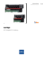
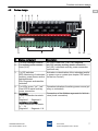
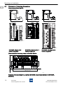
Betriebsanleitung
DE
Operating instructions
EN
www.stahl-ex.com
DE EN
DE
EN
DE
EN
DE
EN
DE
EN
DE
EN
bus-Träger
bus-Carrier
DE
EN
DE
EN
9419 Yokogawa ALF111 Ausführung
9419 Yokogawa ALF111 version
DE
Betriebsanleitung
DE
Zusätzliche Sprachen: www.stahl-ex.com
DE
DE
DE
DE
DE
DE
DE
DE
DE
DE
DE
DE
DE
DE
DE
DE
DE
DE
bus-Träger
DE
DE
DE
9419 Yokogawa ALF111 Ausführung
DE
DE
DE
DE
DE
Inhaltsverzeichnis
DE
1
Allgemeine Angaben ...........................................................................................3
1.1 Hersteller .............................................................................................................3
1.2 Angaben zur Betriebsanleitung ...........................................................................3
1.3 Weitere Dokumente ............................................................................................3
1.4 Konformität zu Normen und Bestimmungen .......................................................3
2
Erläuterung der Symbole ....................................................................................3
2.1 Symbole in der Betriebsanleitung .......................................................................3
2.2 Warnhinweise .....................................................................................................4
2.3 Symbole am Gerät oder in Schaltplänen ............................................................4
3
Sicherheitshinweise ............................................................................................5
3.1 Aufbewahrung der Betriebsanleitung ..................................................................5
3.2 Sichere Verwendung ...........................................................................................5
3.3 Umbauten und Änderungen ................................................................................5
4
Funktion und Geräteaufbau ................................................................................6
4.1 Funktion ..............................................................................................................6
4.2 Geräteaufbau ......................................................................................................7
5
Technische Daten ...............................................................................................8
6
Projektierung .....................................................................................................10
7
Transport und Lagerung ...................................................................................10
8
Montage und Installation ...................................................................................11
8.1 Maßangaben / Befestigungsmaße ....................................................................12
8.2 Montage / Demontage, Gebrauchslage ............................................................13
8.3 Installation .........................................................................................................15
9
Parametrierung und Inbetriebnahme ................................................................19
9.1 DIP-Schalter am bus-Träger .............................................................................20
10 Betrieb ...............................................................................................................21
10.1 Betrieb ...............................................................................................................21
10.2 Anzeigen ...........................................................................................................21
10.3 Fehlerbeseitigung .............................................................................................21
11 Instandhaltung, Wartung, Reparatur .................................................................22
11.1 Instandhaltung ..................................................................................................22
11.2 Wartung ............................................................................................................22
11.3 Reparatur ..........................................................................................................22
11.4 Rücksendung ....................................................................................................23
12 Entsorgung ........................................................................................................23
13 Zubehör und Ersatzteile ...................................................................................23
EG-Konformitätserklärung / EC-Declaration of Conformity ........................................24
DE
DE
DE
DE
DE
DE
DE
DE
DE
DE
DE
DE
DE
DE
DE
DE
DE
DE
DE
DE
DE
DE
DE
2
Allgemeine Angaben
1
Allgemeine Angaben
1.1
Hersteller
1.2
1.3
1.4
DE
DE
DE
R. STAHL Schaltgeräte GmbH
Am Bahnhof 30
74638 Waldenburg
Germany
DE
Tel.:
+49 7942 943-0
Fax:
+49 7942 943-4333
Internet: www.stahl-ex.com
DE
Angaben zur Betriebsanleitung
ID-Nr.:
Publikationsnummer:
Hardware-Revison:
DE
DE
DE
DE
DE
DE
222558/941960310060
2013-05-29 BA00 III de 00
A
DE
DE
DE
Weitere Dokumente
DE
• Betriebsanleitung Feldbus Stromversorgung 9412
• Operating Instructions Fieldbus Power Supply 9412
• Betriebsanleitung Diagnose Kommunikations Modul 9415
• Operating Instructions Diagnosis Communication Module 9415
• Datenblatt bus-Träger 9419 Yokogawa ALF111
• Data sheet bus-Carrier 9419 Yokogawa ALF111
Weitere Sprachen, siehe www.stahl-ex.com.
DE
DE
DE
DE
DE
DE
Konformität zu Normen und Bestimmungen
Siehe Zertifikate und EG-Konformitätserklärung: www.stahl-ex.com.
DE
2
Erläuterung der Symbole
DE
2.1
Symbole in der Betriebsanleitung
Symbol
DE
DE
Bedeutung
Tipps und Empfehlungen zum Gebrauch des Geräts
Gefahr Allgemein
Gefahr durch explosionsfähige Atmosphäre!
222558/941960310060
2013-05-29 BA00 III de 00
bus-Träger
9419 Yokogawa ALF111
3
Erläuterung der Symbole
DE
DE
2.2
DE
DE
DE
DE
DE
Warnhinweise
Warnhinweise unbedingt befolgen, um das konstruktiv und durch den Betrieb bedingte
Risiko zu minimieren. Die Warnhinweise sind wie folgt aufgebaut:
• Signalwort: GEFAHR, WARNUNG, VORSICHT, HINWEIS
• Art und Quelle der Gefahr/des Schadens
• Folgen der Gefahr
• Ergreifen von Gegenmaßnahmen zum Vermeiden der Gefahr/des Schadens
GEFAHR
DE
Gefahren für Personen
Nichtbeachtung der Anweisung führt zu schweren oder tödlichen Verletzungen bei Personen.
DE
DE
DE
DE
WARNUNG
DE
Gefahren für Personen
Nichtbeachtung der Anweisung kann zu schweren oder tödlichen Verletzungen bei Personen führen.
DE
DE
DE
VORSICHT
DE
Gefahren für Personen
Nichtbeachtung der Anweisung kann zu geringfügigen oder leichten Verletzungen bei Personen führen.
DE
DE
DE
DE
HINWEIS
DE
Vermeidung von Sachschaden
Nichtbeachtung der Anweisung kann zu einem Sachschaden am Gerät und/oder seiner
Umgebung führen.
DE
DE
DE
2.3
Symbole am Gerät oder in Schaltplänen
Symbol
Bedeutung
CE-Kennzeichnung gemäß aktuell gültiger Richtlinie.
05594E00
02198E00
4
Stromkreis gemäß Kennzeichnung für explosionsgefährdete Bereiche zugelassen.
bus-Träger
9419 Yokogawa ALF111
222558/941960310060
2013-05-29 BA00 III de 00
Sicherheitshinweise
3
Sicherheitshinweise
3.1
Aufbewahrung der Betriebsanleitung
3.2
3.3
DE
DE
DE
• Betriebsanleitung sorgfältig lesen und am Einbauort des Geräts aufbewahren.
• Mitgeltende Dokumente und Betriebsanleitungen der anzuschließenden Geräte beachten.
DE
Sichere Verwendung
DE
• Sicherheitshinweise in dieser Betriebsanleitung lesen und beachten!
• Gerät nur bestimmungsgemäß und nur für den zugelassenen Einsatzzweck verwenden.
• Für Schäden, die durch fehlerhaften oder unzulässigen Einsatz sowie durch Nichtbeachtung dieser Betriebsanleitung entstehen, besteht keine Haftung.
• Vor Installation und Inbetriebnahme sicherstellen, dass das Gerät unbeschädigt ist.
• Arbeiten am Gerät (Installation, Instandhaltung, Wartung, Störungsbeseitigung) nur
von dazu befugtem und entsprechend geschultem Personal durchführen lassen.
• Bei Installation und im Betrieb die Angaben (Kennwerte und Bemessungsbetriebsbedingungen) auf Typ- und Datenschildern sowie die Hinweisschilder am Gerät beachten.
• Bei Betriebsbedingungen, die von den technischen Daten abweichen, unbedingt bei
der R.STAHL Schaltgeräte GmbH rückfragen.
• Das Gerät in Zone 2, 22 oder außerhalb explosionsgefährdeter Bereiche installieren.
• Bei Einsatz in Zone 2, 22 das Gerät in ein Gehäuse einbauen, das den Anforderungen
der EN 60079-15 genügt.
• Bei Betrieb in explosionsgefährdeten Bereichen sind Anschlussarbeiten am busTräger nicht zulässig!
• Der bus-Träger enthält Bauteile, die durch elektrostatische Entladungen beschädigt
werden können. Vor Arbeiten am bus-Träger Körper an geerdeten Metallteilen entladen bzw. ein ESD-Ableitband anlegen.
• Bei Anschluss eigensicherer Segmente Norm IEC/EN 60079-25 für den Einsatz von
eigensicheren Systemen in explosionsgefährdeten Bereichen befolgen.
• Bei Anschluss eigensicherer (ic) Segmente am bus-Träger, sicherstellen, dass die "icAbdeckung" montiert ist, um den geforderten Trennabstand zwischen den Anschlussklemmen der Hilfsenergie und der Segmente zu gewährleisten.
• Am bus-Träger gleichzeitig entweder nur eigensichere (ic) oder nicht-eigensichere
Segmente betreiben. Eine Mischbestückung ist nicht zulässig!
• Die maximal zulässige Umgebungstemperatur ist abhängig von Anzahl und den Betriebsmodi der eingesetzten Feldbus Stromversorgungen sowie der Einbaulage des
bus-Trägers. Siehe dazu Angaben in der Betriebsanleitung der Feldbus Stromversorgung 9412.
Umbauten und Änderungen
WARNUNG
Gefahr durch Umbauten und Änderungen am Gerät!
Explosionsschutz gefährdet!
• Gerät nicht umbauen oder verändern.
• Für Schäden, die durch Umbauten und Änderungen entstehen, besteht
keine Haftung und keine Gewährleistung.
222558/941960310060
2013-05-29 BA00 III de 00
bus-Träger
9419 Yokogawa ALF111
5
DE
DE
DE
DE
DE
DE
DE
DE
DE
DE
DE
DE
DE
DE
DE
DE
DE
DE
DE
DE
Funktion und Geräteaufbau
DE
DE
4
Funktion und Geräteaufbau
WARNUNG
DE
Gefahr durch zweckentfremdete Verwendung!
Explosionsschutz gefährdet!
• Gerät ausschließlich entsprechend den in dieser Betriebsanleitung festgelegten Betriebsbedingungen verwenden.
• Gerät in explosionsgefährdeten Bereichen nur gemäß dieser Betriebsanleitung betreiben.
DE
DE
DE
DE
DE
DE
4.1
DE
DE
DE
DE
DE
DE
DE
DE
DE
DE
DE
DE
DE
DE
DE
DE
6
Funktion
Der bus-Träger ist ein in der Schutzart Ex nA ausgeführtes elektrisches Gerät:
• für den Einsatz in explosionsgefährdeten Bereichen der Zone 2 oder im sicheren Bereich,
• zum Anschluss von Feldbussegmenten an die Feldbus Stromversorgung 9412,
• zum Anschluss des AKB336-Systemkabels über integrierte Stecker,
• zur Versorgung von Feldbus Stromversorgungen mit Hilfsenergie (simplex oder redundant),
• zur Meldung von Leitungsfehlern und Hilfsenergieausfällen über Meldekontakte am
bus-Träger.
Der Ausgangsstromkreis ist bei Einsatz einer Feldbus Stromversorgung Typ 9412/0.-3.01. gemäß dem Schutzniveau Ex ic IIC spannungsbegrenzt. Durch Nachschalten einer
entsprechend ausgelegten Strombegrenzung, z.B. Feldgeräte-Koppler Typ 9410/34, ergibt sich ein eigensicherer Stromkreis des Schutzniveaus Ex ic.
Das optional erhältliche Diagnose Kommunikations Modul Typ 9415 wird auf den vorgesehenen Steckplatz am bus-Träger installiert und kann
• Diagnoseinformationen der angeschlossenen Feldbus Segmente (an bus-Träger bzw.
an Feldbus Stromversorgung) sammeln,
• Diagnoseinformationen über Segmente oder ein separates Diagnosesegment an das
Leitsystem übertragen.
Folgende bus-Träger sind derzeit erhältlich:
• 9419/08F-YO1-...: simplex Spannungsversorgung von 8 Feldbus Segmenten
• 9419/04R-YO1-...: redundante Spannungsversorgung von 4 Feldbus Segmenten
• 9419/08R-YO1-...: redundante Spannungsversorgung von 8 Feldbus Segmenten
bus-Träger
9419 Yokogawa ALF111
222558/941960310060
2013-05-29 BA00 III de 00
Funktion und Geräteaufbau
4.2
DE
Geräteaufbau
1
2
3 4
DE
5
6
DE
7
DE
DE
DE
DE
DE
DE
DE
DE
DE
DE
DE
DE
9
8
10
11
DE
12
15514E00
DE
DE
#
Gerätelement
Beschreibung
DE
1
2 x Fehlermeldekontakte
PF (5/6): Power Fail, Dia (7/8): Diagnose
DE
2
2 x Hilfsenergieanschluss
(24 V)
pri (1/2): primärer Hilfsenergieanschluss
red (3/4): redundanter Hilfsenergieanschluss
(Verwendung optional)
DE
3
DE
2 x DIP-Schalter
Aktivierung bzw. Deaktivierung der redundanten
RED: Überwachung RedunHilfsenergie bzw. des Fehlerkontaktes (siehe Kadante Hilfsenergieversorgung pitel "DIP-Schalter am bus-Träger")
aktiviert/deaktiviert
DIA: Diagnose aktiviert/deaktiviert
4
2 x LED grün, "pri", "red"
Betriebsanzeige Hilfsenergieversorgung (primär
Je eine LED pro Hilfsenergie- oder redundant)
anschluss
5
9419/08F:
Anschlussklemmen 2-polig
(+, - )
Segment 1 ... Segment 8
9419/04R, 9419/08R:
Anschlussklemmen 3-polig
(+, - , S)
Segment 1 ... Segment 4 / 8
222558/941960310060
2013-05-29 BA00 III de 00
Anschluss der Feldbussegmente für Feldgeräte
(Trunk connection)
bus-Träger
9419 Yokogawa ALF111
7
DE
DE
DE
Technische Daten
DE
DE
6
Schirmklemme an Schirmschiene (Zubehörteile)
Auflage des Schirms der Segmentzuleitung auf
Schirmschiene (Zubehör, bei 9419/08F im Lieferumfang). Optional sind als Zubehör Schirmklemmen erhältlich, über die die jeweiligen
Anschlusskabel der Segmente an die Schirmschiene angeschlossen werden. Der Erdungsschirm kann alternativ an die Schirmklemme "S"
jeder einzelnen Feldbusklemme angeschlossen
werden.
7
Schirmsammel-Klemme PA/
shield
Potentialausgleich PA/shield; Verbindung zu
Schirmschiene und Schirmklemmen "S".
8
Steckplatz für Feldbus Strom- Übertragung der externen Hilfsenergie an die einversorgung
zelnen Feldbus Stromversorgungen
Typ 9412 auf pac-bus
9
Fußriegel
10
Steckplatz für Diagnose Kom- Installation von Modul Typ 9415
munikations Modul (DCM)Typ
9415
11
DCM-Anschluss
Flachbandanschluss für Modul Typ 9415
12
Anschluss Host-Steckverbindung
(4 Steckplätze)
Host-Steckverbindung für Yokogawa Systemkabel AKB336
DE
DE
DE
DE
DE
DE
DE
DE
DE
DE
DE
DE
DE
DE
DE
DE
DE
DE
DE
DE
5
Technische Daten
DE
Explosionsschutz
DE
Global (IECEx)
DE
Einrastmechanik auf Hutschiene
Gas
IECEx BVS 09.0042X
Ex nA nC IIC T4 Gc
Europa (ATEX)
Gas
BVS 09 ATEX E 100 X
E II 3 G Ex nA nC IIC T4 Gc
Bescheinigungen und
Zulassungen
Bescheinigungen
ATEX, IECEx
Weitere Zulassungen
Schiffszulassung (DNV)
Weitere Parameter
8
Installation
Zone 2, sicherer Bereich
Weitere Angaben
siehe jeweilige Bescheinigung und Betriebsanleitung
bus-Träger
9419 Yokogawa ALF111
222558/941960310060
2013-05-29 BA00 III de 00
Technische Daten
DE
Technische Daten
DE
Elektrische Daten
DE
Hilfsenergie
DE
Nennspannung
UN
24 V DC
Spannungsbereich
19 ... 32 V
DE
DE
DE
DE
Restwelligkeit in- ( 3.6 VSS
nerhalb des
Spannungsbereichs
DE
DE
DE
Redundante Ein- ja, diodenentkoppelt
speisung
DE
Verpolschutz
ja
DE
Betriebsanzeige
2 LED, grün "pri", "red"
DE
Geprüft nach folgenden Normen und Vorschriften:
EN 61326-1 Einsatz im industriellen Bereich;
NAMUR NE 21
DE
Power Fail (pri /
red)
Kontakt "PF" (35 V / 100 mA), im Gutzustand geschlossen
DE
Diagnose
Kontakt "Dia" (35 V / 100 mA), im Gutzustand geschlossen
DE
Elektromagnetische
Verträglichkeit
DE
DE
Fehlererkennung
DE
Umgebungsbedingungen
DE
DE
Umgebungstempe- -20 ... +70 °C
ratur
DE
DE
weitere Angaben siehe Betriebsanleitung des Typs 9412
Lagertemperatur
-40 ... +80 °C
Relative Feuchte
(keine Betauung)
< 95 %
Verwendung in
Höhe
< 2000 m
DE
Mechanische Daten
Anschluss
Trunk
an den Klemmen des bus-Trägers oder der Feldbus Stromversorgung
Host / red. Host
über Systemstecker für Yokogawa AKB336 Systemkabel
DCM
über Flachbandkabel mit Steckverbindern
Schirm
über integrierte Schirmschiene oder an Klemmenanschlüsse "S"
222558/941960310060
2013-05-29 BA00 III de 00
bus-Träger
9419 Yokogawa ALF111
9
Projektierung
DE
DE
Technische Daten
DE
Anschlussquerschnitt
DE
steckbare
Schraubklemmen
Anschluss einadrig
- starr
- flexibel
- flexibel mit
Aderendhülsen
(ohne / mit
Kunststoffhülse)
DE
DE
DE
DE
DE
DE
Anschluss zweiadrig
- starr
- flexibel
- flexibel mit
Aderendhülsen
DE
DE
DE
0,2 ... 2,5 mm2
0,2 ... 2,5 mm2
0,25 ... 2,5 mm2
0,2 ... 1 mm2
0,2 ... 1,5 mm2
0,25 .. 1 mm2
DE
DE
DE
DE
Montageart
auf Hutschiene (NS35/15, NS35/7,5) oder Montageplatte (4 x Schraube M6)
Einbaulage
senkrecht oder waagrecht
weitere Angaben siehe Betriebsanleitung des Typs 9412
DE
DE
DE
DE
DE
DE
Schutzart
IP00
Klemmen
IP20
Gehäusematerial
PA 6.6
Brandfestigkeit
(UL-94)
V0
Änderungen Technische Daten
DE
DE
Änderungen der technischen Daten, Maße, Gewichte, Konstruktionen
und der Liefermöglichkeiten bleiben vorbehalten. Die Abbildungen
sind unverbindlich.
Weitere technische Daten dem aktuellen Datenblatt entnehmen.
6
Projektierung
HINWEIS
Unzulässig hohe Umgebungstemperatur im Schaltschrank!
Ausfall des Geräts möglich!
• Sicherstellen, dass der Betrieb des Geräts im zulässigen Temperaturbereich
möglich ist. Schaltschrank entsprechend aufbauen.
7
10
Transport und Lagerung
• Gerät nur in Originalverpackung transportieren und lagern.
• Gerät trocken (keine Betauung) und erschütterungsfrei lagern.
• Gerät nicht stürzen.
bus-Träger
9419 Yokogawa ALF111
222558/941960310060
2013-05-29 BA00 III de 00
Montage und Installation
8
DE
Montage und Installation
Das Gerät kann außerhalb und innerhalb von explosionsgefährdeten Bereichen der Zone
2, 22 installiert werden.
GEFAHR
Gerät in explosionsgefährdeten Bereichen nicht ohne Gehäuse installieren!
Explosionsschutz gefährdet!
• Zum Betrieb in der Zone 2, 22 das Gerät in ein geeignetes Gehäuse einbauen, das mindestens den Anforderungen der IEC/EN 60079-15 entspricht.
DE
DE
DE
DE
DE
DE
DE
DE
DE
GEFAHR
Gefahr durch falsche Installation des Geräts!
Explosionsschutz gefährdet!
• Installation strikt nach Anleitung und unter Berücksichtigung der nationalen Sicherheits- und Unfallverhütungsvorschriften (z.B. IEC/EN
60079-14) durchführen, damit der Explosionsschutz erhalten bleibt.
• Das Gerät nur durch geschultes Fachpersonal installieren lassen. Dazu
sind Kenntnisse der einschlägigen Normen (z.B. IEC/EN 60079-14) unbedingt erforderlich.
DE
DE
DE
DE
DE
DE
DE
DE
HINWEIS
DE
Elektrostatisch gefährdete Bauelemente!
Ausfall des Geräts möglich!
• Vor Arbeiten am bus-Träger Körper an geerdeten Metallteilen entladen bzw. ein
ESD-Ableitband anlegen.
DE
DE
DE
DE
DE
DE
222558/941960310060
2013-05-29 BA00 III de 00
bus-Träger
9419 Yokogawa ALF111
11
Montage und Installation
DE
DE
8.1
DE
Maßangaben / Befestigungsmaße
Maße bus-Träger
DE
DE
129 mm / 5.08 "
129 mm / 5.08 "
DE
129 mm / 5.08 "
DE
DE
DE
161 mm / 6.34 "
161 mm / 6.34 "
161 mm / 6.34 "
DE
DE
DE
DE
DE
358 mm / 14.09 "
DE
217 mm / 8.54 "
252 mm / 9.92 "
DE
DE
DE
DE
15300E00
DE
15301E00
DE
DE
DE
DE
15455E00
9419/08F, simplex für 8
Feldbus-Segmente
DE
9419/04R, redundant für 4
Feldbus-Segmente
9419/08R, redundant für 8
Feldbus-Segmente
10,6 mm
0.42 "
71,3 mm
2.81 "
6 mm 64,6 mm / 2.54 "
0.24 "
27,7 mm / 1.09 "
160,3 mm / 6.31 "
Maße für Montagelöcher am bus-Träger
122,9 mm / 4.84 "
122,9 mm / 4.84 "
35,4 mm / 1.39 "
27,1 mm / 1.07 "
18,7 mm / 0.74 "
358,4 mm / 14.11 "
15650E00
Positionen der Montagelöcher, Beispiel 9419/08R. Entsprechend gültig auch für 9419/08F,
9419/04R.
12
bus-Träger
9419 Yokogawa ALF111
222558/941960310060
2013-05-29 BA00 III de 00
Montage und Installation
8.2
DE
Montage / Demontage, Gebrauchslage
Gebrauchslage
Der bus-Träger kann waagrecht oder senkrecht auf einer Hutschiene oder einer Montageplatte montiert werden.
DE
DE
DE
DE
8.2.1 Montage / Demontage auf Hutschiene
• bus-Träger auf Hutschiene (entsprechend EN 50022, Typ
NS 35/7,5 oder NS 35/15) ansetzen und so aufschwenken, dass der Fußriegel bzw. die beiden Fußriegel (nur
bei Typ 9419/08R) einrasten (siehe nebenstehende Abbildung).
DE
DE
DE
DE
DE
DE
DE
DE
08032E00
DE
• Demontage in umgekehrter Reihenfolge.
DE
DE
DE
DE
DE
DE
15633E00
DE
10,6 mm
0.42 "
71,3 mm
2.81 "
6 mm 64,6 mm / 2.54 "
0.24 "
27,7 mm / 1.09 "
160,3 mm / 6.31 "
8.2.2 Montage / Demontage auf Montageplatte
122,9 mm / 4.84 "
122,9 mm / 4.84 "
35,4 mm / 1.39
27,1 mm / 1.07 "
18,7 mm / 0.74 "
358,4 mm / 14.11 "
• bus-Träger über vorhandene Montagelöcher mit mindestens 4 Schrauben M5
bzw. 6 Schrauben M5 (Typ
9419/08R) auf Montageplatte festschrauben. Siehe nebenstehende Zeichnung.
• Demontage in umgekehrter
Reihenfolge.
15650E00
222558/941960310060
2013-05-29 BA00 III de 00
bus-Träger
9419 Yokogawa ALF111
13
DE
DE
DE
DE
Montage und Installation
DE
DE
8.2.3 Montage / Demontage Feldbus Stromversorgung auf bus-Träger
DE
DE
Vor der Montage der Feldbus Stromversorgung müssen alle Klemmen und
Abdeckungen auf der Seite des Fußriegels entfernt werden.
Beim Aufschwenken des Geräts auf den bus-Träger darauf achten, dass das
Gehäuse der Feldbus Stromversorgung nicht verkantet.
DE
DE
DE
DE
Montage
DE
• Abdeckung an der obersten Klemme sowie schwarze und
grüne Schraubklemmen am Gerät auf der Seite des
Fußriegels mit Schraubendreher entfernen.
• Schraubendreher hinter jeweiliger Klemme bzw. unter der
Abdeckung ansetzen und Klemme bzw. Abdeckung aus
dem Gehäuse herausdrücken.
DE
DE
DE
DE
DE
DE
15701E00
DE
DE
DE
DE
DE
DE
DE
15569E00
DE
DE
DE
• Gerät am entsprechenden Steckplatz ansetzen und auf
bus-Träger aufschwenken.
• Danach das Gerät bis zum roten Rasthebel einschwenken.
• Sicherstellen, dass der rote Rasthebel in die Aussparung
des Geräts greift.
• Roten Rasthebel durch schrägen Druck mit dem Daumen
auf den Hebel schließen. Dabei gleichzeitig mit dem Zeigefinger an der Gegenseite des Geräts drücken. Daumen
und Zeigefinger bilden einen Klammergriff.
• Daumen und Zeigefinger solange drücken, bis der rote
Rasthebel hörbar am Gerät einrastet.
15572E00
Demontage
• Schraubendreher in den roten Rasthebel stecken und
Rasthebel mit einer Schwenkbewegung öffnen.
• Gerät vom Steckplatz schwenken und entnehmen.
15574E00
14
bus-Träger
9419 Yokogawa ALF111
222558/941960310060
2013-05-29 BA00 III de 00
Montage und Installation
DE
8.2.4 Montage / Demontage ic-Abdeckung
DE
DE
Die ic-Abdeckung dient zur elektrischen Trennung von eigensicheren (ic)
Segmenten am bus-Träger und den Anschlussklemmen der Hilfsenergie.
Die ic-Abdeckung vor dem Anschließen der Hilfsenergie-und Fehlermeldeleitungen montieren. Die Abdeckung während des Betriebs nicht entfernen!
DE
DE
DE
DE
DE
• Die ic-Abdeckung über die Anschlussklemmen für den Hilfsenergieanschluss stecken.
• Darauf achten, dass das Nietloch in der Abdeckung deckungsgleich mit der Lochbohrung in der Leiterplatte liegt.
• Die ic-Abdeckung mit dem beiliegenden Niet an der Leiterplatte befestigen.
• Demontage in umgekehrter Reihenfolge.
DE
DE
DE
DE
DE
8.3
DE
Installation
Bei der Installation sind folgende Punkte zu beachten:
DE
DE
Hinweise im Kapitel "Sichere Verwendung" befolgen!
DE
DE
DE
8.3.1 Feldbus-Anschlusskabel anschließen
Schirmklemme an Schirmschiene:
18 mm
0.71 "
40 mm
1.57 "
7 mm
0.28 "
15525E00
222558/941960310060
2013-05-29 BA00 III de 00
DE
• Anschlusskabel und Kabeladern gemäß Zeichnung abisolieren.
• Sicherstellen, dass beim Abisolieren der Schirm bzw. die
Adern nicht beschädigt werden.
• Einzeladern des Anschlusskabels an die entsprechenden
Klemmen "+" und "-" der Feldbusklemme anschließen.
• Das Anschlusskabel mit Schirm mittels Schirmklemme
(Zubehör) an der Schirmschiene unterklemmen.
• Vorgang für weitere Anschlusskabel wiederholen.
bus-Träger
9419 Yokogawa ALF111
15
DE
DE
DE
DE
DE
Montage und Installation
DE
Schirmklemme "S" an Feldbusklemme:
DE
DE
DE
40 mm
1.57 "
DE
7 mm
0.28 "
15526E00
DE
DE
DE
DE
DE
DE
DE
DE
DE
8.3.2 Bus-Träger an Potentialausgleich anschließen
Schirmsammel-Klemme PA/shield mit dem Erdungsnetz verbinden, um Potentialausgleich herzustellen.
DE
Die Angaben zur korrekten Erdung und Schirmung von Feldbusinstallationen
im FF AG 181 beachten.
DE
DE
DE
DE
• Anschlusskabel gemäß Zeichnung abisolieren.
• Sicherstellen, dass beim Abisolieren der Schirm bzw. die
Adern nicht beschädigt werden. Schirm über das Anschlusskabel legen.
• Einzeladern des Anschlusskabels an die entsprechenden
Klemmen "+" und "-" der Feldbusklemme anschließen.
• Einen aus dem Schirm verdrillten Abzweig bilden. Diesen
teilweise mit einem Schrumpfschlauch überziehen. Das
freie Ende (schwarz) zwecks Erdung in die Schirmklemme "S" der Feldbusklemme stecken und festschrauben.
• Vorgang für weitere Anschlusskabel wiederholen.
8.3.3 Feldbussegmente anschließen
DE
Die Schirmung (Erdung PA/shield) der Feldbus-Anschlusskabel wird durch
das Festklemmen unter die Schirmschiene hergestellt (max. Anzugsdrehmoment: 0,7 Nm). Optional kann der Feldbus-Anschluss an der Schirmklemme
"S" des jeweiligen Anschlusses geerdet werden.
Beim 9419/08F-bus-Träger (8-fach simplex) existieren keine
Schirmklemmenanschlüsse "S"!
DE
DE
DE
DE
DE
9419/08F-YO1-...:
• Anschlusskabel abisolieren (siehe Kapitel "Feldbus-Anschlusskabel anschließen").
• Trunk an die Klemmen "+ / -" für jeden Feldbus-Stromkreis anschließen.
• Host Systemstecker an "Host 1 to 4" und "Host 5 to 8" für den Feldbus-Stromkreis
anschließen.
• Schirm an der Schirmklemme anschließen. Feldbus ist angeschlossen.
15652E00
16
bus-Träger
9419 Yokogawa ALF111
222558/941960310060
2013-05-29 BA00 III de 00
Montage und Installation
9419/04R-YO1-...:
• Anschlusskabel abisolieren (siehe Kapitel "Feldbus-Anschlusskabel anschließen").
• Host Systemstecker an "Host A 1 to 4" für den Feldbus-Stromkreis anschließen.
• Redundanten Host Steckverbinder an "Host B 1 to 4" für den Feldbus-Stromkreis
anschließen.
• Trunk an die Klemmen "+ / - / S" für jeden Feldbus-Stromkreis anschließen.
• Schirm des Anschlusskabels an Klemme "S" oder an Schirmklemme anschließen
(Schirmklemmen separat bestellen, nicht im Lieferumfang). Feldbus ist redundant angeschlossen.
DE
DE
DE
DE
DE
DE
DE
DE
DE
DE
DE
DE
DE
DE
15653E00
9419/08R-YO1-..:
• Anschlusskabel abisolieren (siehe Kapitel "Feldbus-Anschlusskabel anschließen").
• Host Systemstecker an "Host A 1 to 4" und "Host A 5 to 8" für den Feldbus-Stromkreis
anschließen.
• Redundanten Host Steckverbinder an "Host B 1 to 4" und "Host B 5 to 8" für den Feldbus-Stromkreis anschließen.
• Trunk an die Klemmen "+ / - / S" für jeden Feldbus-Stromkreis anschließen.
• Schirm des Anschlusskabels an Klemme "S" oder an Schirmklemme anschließen
(Schirmklemmen separat bestellen, nicht im Lieferumfang). Feldbus ist redundant angeschlossen.
DE
DE
DE
DE
DE
DE
DE
DE
DE
DE
DE
15651E00
8.3.4 Fehlermeldekontakte anschließen
Im Auslieferungszustand sind die Fehlermeldekontakte "PF" (Power Fail) und
"Dia" (Diagnose) mit einer Brücke verbunden, so dass nur eine Sammelmeldung "Fehler" je bus-Träger erfolgt.
Durch Entfernen der Drahtbrücke können beide Relaiskontakte separat verwendet werden. Position der Klemmen, siehe Kapitel "Funktion und
Geräteaufbau".
222558/941960310060
2013-05-29 BA00 III de 00
bus-Träger
9419 Yokogawa ALF111
17
Montage und Installation
DE
Sammelmeldung "Fehler"
• Fehlermeldekontakte an den Klemmen "5" und "8"
des bus-Trägers anschließen.
• Die Kontaktbrücke zwischen den Klemmen "6"
und "7" muss gesteckt bleiben (Auslieferungszustand).
DE
DE
DE
DE
pri 24 V DC red
3+ 41+ 2PF
Dia
5 6
7 8
DE
DE
Fehlermeldekontakt "PF" (Power Fail)
• Drahtbrücke zwischen Klemme "6" und "7" entfernen.
• Fehlermeldekontakte an den Klemmen "5" und "6"
des bus-Trägers anschließen.
Dia
red
DE
red
ON
pri
X101
DE
DE
DE
15655E00
Fehlermeldekontakt "Dia" (Diagnose)
• Drahtbrücke zwischen Klemme "6" und "7" entfernen.
• Fehlermeldekontakte an den Klemmen "7" und "8"
des bus-Trägers anschließen.
DE
DE
DE
DE
DE
DE
DE
8.3.5 Diagnose Kommunikations Modul anschließen
DE
Angaben zum Anschließen des Diagnose Kommunikations Moduls Typ 9415,
siehe entsprechende Betriebsanleitung.
DE
DE
DE
DE
8.3.6 Elektrische Anschlüsse
WARNUNG
DE
Sicherheitstechnische Werte des Geräts und der angeschlossenen
Feldgeräte bei eigensicheren Schnittstellen nicht passend!
Explosionsschutz gefährdet!
• Sicherheitstechnische Werte des Geräts und der angeschlossenen
Feldgeräte entsprechend der nationalen Installationsvorschriften
überprüfen.
DE
Anschlussquerschnitte für anzuschließende Verdrahtung siehe Datenblatt.
18
bus-Träger
9419 Yokogawa ALF111
222558/941960310060
2013-05-29 BA00 III de 00
Parametrierung und Inbetriebnahme
DE
Hilfsenergie anschießen
DE
Die Hilfsenergieversorgung des bus-Trägers kann sowohl simplex als auch
redundant erfolgen. Position der Klemmen, siehe Kapitel "Funktion und
Geräteaufbau."
DE
DE
DE
DE
Simplex Hilfsenergieversorgung
• Hilfsenergie an den Klemmen "1+" und "2-" des
bus-Trägers anschließen.
red
ON
pri
X101
15655E00
DE
DE
DE
Redundante Hilfsenergieversorgung
• Falls erforderlich, redundante Hilfsenergie an den
Klemmen "3+" und "4-" des bus-Trägers
anschließen.
DE
Einstellung DIP-Schalter "RED"
• Siehe Kapitel "Parametrierung und Inbetriebnahme".
DE
Dia
red
pri 24 V DC red
3+ 41+ 2PF
Dia
5 6
7 8
DE
DE
DE
DE
DE
DE
DE
9
DE
Parametrierung und Inbetriebnahme
DE
WARNUNG
Gerät vor der Inbetriebnahme überprüfen!
Explosionsschutz gefährdet!
• Vor der Inbetriebnahme Prüfungsvorschriften in den national gültigen
Bestimmungen beachten, damit der Explosionsschutz erhalten bleibt.
• Gerät vor der Inbetriebnahme auf korrekte Installation und Funktion
überprüfen.
Vor Inbetriebnahme Folgendes sicherstellen:
• das Gerät ist vorschriftsmäßig installiert,
• die Kabel sind richtig angeschlossen,
• das Gerät und die Anschlusskabel sind nicht beschädigt,
• Schrauben an den Klemmen sind fest angezogen. Dabei auf das richtige Anzugsdrehmoment achten (siehe folgende Tabelle).
Anzugsdrehmoment für Schrauben an Klemmen
min.
0,5 Nm
max.
0,6 Nm
222558/941960310060
2013-05-29 BA00 III de 00
bus-Träger
9419 Yokogawa ALF111
19
DE
DE
DE
DE
DE
Parametrierung und Inbetriebnahme
DE
DE
9.1
DIP-Schalter am bus-Träger
GEFAHR
DE
DIP-Schalter am Gerät nicht unter Spannung ändern!
Explosionsschutz gefährdet!
• Die DIP-Schalter-Einstellungen am Gerät in Zone 2 unter Spannung keinesfalls ändern!
• Zum Ändern der DIP-Schalter Gerät spannungslos schalten!
DE
DE
DE
DE
DE
DE
Bei simplex Hilfsenergieversorgung muss der DIP-Schalter "RED" auf "ON"
gestellt werden, ansonsten wird die fehlende redundante Hilfsenergieversorgung als Fehler gemeldet.
DE
DE
DE
DE
DE
9.1.1 DIP-Schalter "RED" - Redundante Hilfsenergie
DE
Bei der Auslieferung ist die redundante Hilfsenergie aktiviert. Der DIP-Schalter "RED" steht dabei auf "OFF".
DE
DE
DE
DE
DE
DE
DE
DE
DE
Simplex
Hilfsenergie an
Redundante
Hilfsenergie an
ON OFF
RED
DIA
ON OFF
RED
DIA
15521E00
15522E00
9.1.2 DIP-Schalter "DIA"- Fehlerkontakt
DE
Bei der Auslieferung ist der Fehlerkontakt aktiviert. Der DIP-Schalter "DIA"
steht dabei auf "OFF".
Fehlermeldungen
Fehlermeldungen
werden unterdrückt aktiviert
ON OFF
RED
DIA
ON OFF
RED
DIA
15523E00
20
bus-Träger
9419 Yokogawa ALF111
15524E00
222558/941960310060
2013-05-29 BA00 III de 00
Betrieb
10
DE
Betrieb
DE
DE
10.1 Betrieb
Nach Bestückung mit Feldbus Stromversorgungen und entsprechenden Inbetriebnahmeschritten (siehe Kapitel "Parametrierung und Inbetriebnahme"), die Hilfsenergieversorgung des bus-Trägers einschalten.
10.2 Anzeigen
Am bus-Träger zeigen 2 grüne LEDs den Betriebszustand der Hilfsenergieversorgung
an.
Die LEDs "pri" und "red" sind den jeweiligen Hilfsenergieanschlüssen zugeordnet
(primär, redundant). Nur wenn der entsprechende Hilfsenergieanschluss aktiv ist, leuchtet die zugeordnete LED.
LED
Farbe Zustand
Beschreibung/Fehlerursache
LED
"pri"
grün
an
simplex Hilfsenergie vorhanden
aus
simplex Hilfsenergie ausgefallen
(Spannung < 19 V)
LED
"red"
grün
an
redundante Hilfsenergie vorhanden
aus
redundante Hilfsenergie ausgefallen
(Spannung < 19 V)
DE
DE
DE
DE
DE
DE
DE
DE
DE
DE
DE
DE
DE
DE
DE
DE
10.3 Fehlerbeseitigung
DE
GEFAHR
Fehler am Gerät!
Explosionsschutz gefährdet!
Festgestellte Fehler, die sich auf den Explosionsschutz auswirken, sofort beseitigen.
• Das Gerät außer Betrieb setzen!
• Das Gerät spannungsfrei schalten!
• Fehlerursache beseitigen!
• Das Gerät wieder in Betrieb nehmen.
Bei der Fehlerbeseitigung folgenden Fehlersuchplan beachten:
Fehler
Fehlerursache
Fehlerbehebung
LED "pri" und/oder LED
• Simplex und/oder
• Polarität der Hilfsenergiever"red" erloschen
redundante Hilfssorgung kontrollieren.
energie ausgefallen
• Verdrahtung der Hilfsener(Spannung < 19 V)
gieversorgung kontrollieren.
• Hilfsenergieversorgung verpolt
• Diagnose über DIP-Schalter
Kein Diagnosesignal
• Diagnose deaktiviert.
"DIA" aktivieren.
• Fehlerkontakte nicht
• Verdrahtung der Fehlerkonkorrekt verdrahtet.
takte prüfen.
222558/941960310060
2013-05-29 BA00 III de 00
DE
bus-Träger
9419 Yokogawa ALF111
21
DE
DE
DE
DE
Instandhaltung, Wartung, Reparatur
DE
Wenn sich der Fehler mit den genannten Vorgehensweisen nicht beheben lässt:
• An die nächste Vertriebsniederlassung von R.STAHL Schaltgeräte GmbH wenden.
Zur schnellen Bearbeitung folgende Angaben bereithalten:
• Typ und Seriennummer
• Kaufdaten
• Fehlerbeschreibung
• Einsatzzweck (insbesondere Eingangs-/Ausgangsbeschaltung)
DE
DE
DE
DE
DE
DE
DE
DE
11
Instandhaltung, Wartung, Reparatur
WARNUNG
DE
Unbefugte Arbeiten am Gerät!
Gefahr von Verletzungen und Sachschäden!
• Arbeiten am Gerät ausschließlich von dazu befugtem und entsprechend
geschultem Personal ausführen lassen.
DE
DE
DE
DE
DE
11.1 Instandhaltung
• Art und Umfang der Prüfungen den entsprechenden nationalen Vorschriften entnehmen.
• Prüfungsintervalle an Betriebsbedingungen anpassen.
Bei der Instandhaltung des Geräts mindestens folgende Punkte prüfen:
• fester Sitz der untergeklemmten Leitungen,
• fester Sitz der Systemstecker,
• Rissbildung und andere sichtbare Schäden am Gerätegehäuse und /oder
Schutzgehäuse,
• Einhaltung der zulässigen Umgebungstemperaturen,
• bestimmungsgemäße Funktion.
DE
DE
DE
DE
DE
DE
DE
DE
DE
11.2 Wartung
Das Gerät benötigt keine regelmäßige Wartung.
DE
Die geltenden nationalen Bestimmungen im Einsatzland beachten.
11.3 Reparatur
GEFAHR
Gefahr durch unsachgemäße Wartung/Reparatur!
Explosionsschutz gefährdet!
• Reparaturen am Gerät nur von R.STAHL Schaltgeräte GmbH
durchführen lassen.
22
bus-Träger
9419 Yokogawa ALF111
222558/941960310060
2013-05-29 BA00 III de 00
Entsorgung
DE
11.4 Rücksendung
Für die Rücksendung im Reparatur-/Servicefall das Formular "Serviceschein" verwenden. Auf der Internetseite "www.stahl-ex.com" im Menü "Downloads > Kundenservice":
• Serviceschein herunterladen und ausfüllen.
• Gerät zusammen mit dem Serviceschein wieder in der Originalverpackung an die
R.STAHL Schaltgeräte GmbH senden.
12
13
DE
DE
DE
DE
DE
DE
Entsorgung
• Nationale und lokal gültige Vorschriften und gesetzliche Bestimmungen zur Entsorgung beachten.
• Materialien getrennt dem Recycling zuführen.
• Umweltgerechte Entsorgung aller Bauteile gemäß den gesetzlichen Bestimmungen sicherstellen.
DE
DE
DE
DE
DE
DE
Zubehör und Ersatzteile
DE
HINWEIS
Nur Original-Zubehör und Original-Ersatzteile der R. STAHL Schaltgeräte GmbH verwenden.
DE
DE
DE
DE
Zubehör und Ersatzteile, siehe Datenblatt auf Homepage www.stahl-ex.com.
DE
DE
DE
DE
DE
DE
DE
222558/941960310060
2013-05-29 BA00 III de 00
bus-Träger
9419 Yokogawa ALF111
23
DE
DE
DE
DE
DE
DE
DE
DE
DE
DE
DE
DE
DE
DE
DE
DE
DE
DE
DE
DE
DE
DE
DE
DE
DE
EG-Konformitätserklärung / EC-Declaration of Conformity
Operating Instructions
EN
Additional languages: www.stahl-ex.com
EN
EN
EN
EN
EN
EN
EN
EN
EN
EN
EN
EN
EN
EN
EN
EN
EN
EN
bus-Carrier
EN
EN
EN
9419 Yokogawa ALF111 version
EN
EN
EN
EN
EN
Contents
EN
1
General Information ............................................................................................3
1.1 Manufacturer .......................................................................................................3
1.2 Information regarding the operating instructions .................................................3
1.3 Further documents ..............................................................................................3
1.4 Conformity with standards and regulations .........................................................3
2
Explanation of the symbols .................................................................................3
2.1 Symbols in these operating instructions .............................................................3
2.2 Warning notes .....................................................................................................4
2.3 Symbols on the device or in the circuit diagrams ................................................4
3
Safety notes ........................................................................................................5
3.1 Operating instructions storage ............................................................................5
3.2 Safe use ..............................................................................................................5
3.3 Alterations and modifications ..............................................................................5
4
Function and device design ................................................................................6
4.1 Function ..............................................................................................................6
4.2 Device design .....................................................................................................7
5
Technical data .....................................................................................................8
6
Engineering .......................................................................................................10
7
Transport and storage .......................................................................................10
8
Mounting and installation ..................................................................................11
8.1 Dimensions / fastening dimensions ..................................................................12
8.2 Mounting / dismounting, operating position ......................................................13
8.3 Installation .........................................................................................................15
9
Parameterization and commissioning ...............................................................19
9.1 DIP switch on the bus-Carrier ...........................................................................19
10 Operation ..........................................................................................................20
10.1 Operation ..........................................................................................................20
10.2 Indications .........................................................................................................20
10.3 Troubleshooting ................................................................................................21
11 Maintenance, overhaul and repair ....................................................................22
11.1 Maintenance .....................................................................................................22
11.2 Overhaul ...........................................................................................................22
11.3 Repair ...............................................................................................................22
11.4 Returning the device .........................................................................................22
12 Disposal ............................................................................................................22
13 Accessories and spare parts .............................................................................23
EG-Konformitätserklärung / EC-Declaration of Conformity ........................................24
EN
EN
EN
EN
EN
EN
EN
EN
EN
EN
EN
EN
EN
EN
EN
EN
EN
EN
EN
EN
EN
EN
EN
2
General Information
1
General Information
1.1
Manufacturer
1.2
1.3
1.4
EN
EN
EN
R. STAHL Schaltgeräte GmbH
Am Bahnhof 30
74638 Waldenburg
Germany
EN
Phone.: +49 7942 943-0
Fax:
+49 7942 943-4333
Internet: www.stahl-ex.com
EN
EN
EN
EN
EN
EN
Information regarding the operating instructions
ID-No.:
Publication Code:
Hardware revision:
EN
222558/941960310060
2013-05-29 BA00 III en 00
A
EN
EN
EN
Further documents
EN
• Betriebsanleitung Feldbus Stromversorgung 9412
• Operating Instructions Fieldbus Power Supply 9412
• Betriebsanleitung Diagnose Kommunikations Modul 9415
• Operating Instructions Diagnosis Communication Module 9415
• Datenblatt bus-Träger 9419 Yokogawa ALF111
• Data sheet bus-Carrier 9419 Yokogawa ALF111
For further languages, see www.stahl-ex.com.
EN
EN
EN
EN
EN
EN
Conformity with standards and regulations
EN
See certificates and EC Declaration of Conformity: www.stahl-ex.com.
2
Explanation of the symbols
2.1
Symbols in these operating instructions
Symbol
EN
EN
EN
Meaning
Tips and recommendations on the use of the device
General Danger
Danger due to explosive atmosphere!
222558/941960310060
2013-05-29 BA00 III en 00
bus-Carrier
9419 Yokogawa ALF111 version
3
Explanation of the symbols
EN
EN
2.2
EN
EN
EN
EN
EN
Warning notes
Warning notes must be observed under all circumstances, in order to minimize the risk
due to construction and operation. The warning notes have the following structure:
• Signalling word: DANGER, WARNING, CAUTION, NOTICE
• Type and source of danger/damage
• Consequences of danger
• Taking countermeasures to avoid the danger/damage
DANGER
EN
Danger for persons
Non-compliance with the instruction results in severe or fatal injuries to persons.
EN
EN
EN
WARNING
EN
Danger for persons
Non-compliance with the instruction can result in severe or fatal injuries to
persons.
EN
EN
EN
EN
CAUTION
EN
Danger for persons
Non-compliance with the instruction can result in minor or light injuries to persons.
EN
EN
EN
EN
NOTICE
EN
Avoiding material damage
Non-compliance of the instruction may result in damage to the device and/or its environment.
EN
EN
EN
2.3
Symbols on the device or in the circuit diagrams
Symbol
Meaning
CE marking according to the currently applicable directive.
05594E00
Electric circuit according to marking approved for hazardous areas.
02198E00
4
bus-Carrier
9419 Yokogawa ALF111 version
222558/941960310060
2013-05-29 BA00 III en 00
Safety notes
3
Safety notes
3.1
Operating instructions storage
3.2
3.3
EN
EN
EN
• Read the operating instructions carefully and store them at the mounting location of
the device.
• Observe applicable documents and operating instructions of the devices to be connected.
Safe use
• Read and observe the safety notes in these operating instructions!
• Use the device in accordance with its intended and approved purpose only.
• No liability for damage caused by incorrect or unauthorized use or non-compliance of
these operating instructions.
• Before installation and commissioning, make sure that the device is not damaged.
• Work on the device (installation, maintenance, overhaul, repair) may only be carried
out by appropriately authorized and trained personnel.
• During installation and operation observe the information (characteristic values and
rated operating conditions) on the rating, data and information plates located on the
device.
• Always consult with R.STAHL Schaltgeräte in case of operating conditions which deviate from the technical data.
• Install the device in Zone 2, 22 or outside of the hazardous areas.
• When used in Zone 2, 22, the device must be built into an enclosure which corresponds to the requirements of EN 60079-15.
• When operating the device in hazardous areas, connection work on the bus-Carrier is
not permitted!
• The bus-Carrier contains components that can be damaged by electrostatic discharges. Before carrying out work on the bus-Carrier, the body must be discharged on
earthed metal parts or an ESD wrist strap must be put on.
• When connecting intrinsically safe segments, observe standard IEC/EN 60079-25 for
the use of intrinsically safe systems in hazardous areas.
• When connecting intrinsically safe (ic) segments to the bus-Carrier, make sure that the
provided "ic covering" is mounted to ensure the required distance between the connection terminals of the auxiliary power and the segments.
• Operate simultaneously only intrinsically safe (ic) or non-intrinsically safe segments on
the bus-Carrier. A mixed assembly is not permitted!
• The maximum permissible ambient temperature depends on the number and operating modes of the fieldbus power supplies used and of the installation position of the
bus-Carrier. See information in the operating instructions of the fieldbus power supply
9412.
Alterations and modifications
WARNING
Danger due to alterations and modifications to the device!
Explosion protection is impaired!
• Do not modify or change the device.
• No liability or warranty for damage resulting from alterations and modifications.
222558/941960310060
2013-05-29 BA00 III en 00
bus-Carrier
9419 Yokogawa ALF111 version
5
EN
EN
EN
EN
EN
EN
EN
EN
EN
EN
EN
EN
EN
EN
EN
EN
EN
EN
EN
EN
EN
EN
Function and device design
EN
EN
4
Function and device design
WARNING
EN
Danger due to improper use!
Explosion protection is impaired!
• The device may only be used according to the operating conditions described in these operating instructions.
• Use the device in hazardous areas only according to these operating instructions.
EN
EN
EN
EN
EN
EN
4.1
EN
EN
EN
EN
EN
EN
EN
EN
EN
EN
EN
EN
EN
EN
EN
EN
6
Function
The bus-Carrier is an electrical device with degree of protection Ex nA:
• for the use in hazardous areas of Zone 2 or in the safe area,
• for connecting fieldbus segments to the fieldbus power supply 9412,
• for connecting the AKB336 system cable by means of integrated plugs,
• for supplying fieldbus power supplies with auxiliary power (simplex or redundant),
• for reporting of line faults and auxiliary power failures via message contacts on the
bus-Carrier.
With the fieldbus power supply Type 9412/0.-3.0-1. inserted, the output circuit is voltagelimited according to the protection level Ex ic IIC. Connecting a downstream current limiter of suitable design, e.g., field device coupler Type 9410/34, gives an intrinsically safe
electric circuit of protection level Ex ic.
The optionally available diagnosis communication module Type 9415 is installed on the
intended slot on the bus-Carrier and can
• collect diagnostic information of the connected fieldbus segments (on bus-Carrier or
on fieldbus power supply),
• transmit diagnostic information to the control system via segments or a separate
diagnosis segment.
The following bus-Carriers are currently available:
• 9419/08F-YO1-...: simplex voltage supply of 8 fieldbus segments
• 9419/04R-YO1-...: redundant voltage supply of 4 fieldbus segments
• 9419/08R-YO1-...: redundant voltage supply of 8 fieldbus segments
bus-Carrier
9419 Yokogawa ALF111 version
222558/941960310060
2013-05-29 BA00 III en 00
Function and device design
4.2
EN
Device design
1
2
3 4
EN
5
6
EN
7
EN
EN
EN
EN
EN
EN
EN
EN
EN
EN
EN
EN
9
8
10
11
EN
12
15514E00
EN
EN
#
Device component
Description
EN
1
2 x error message contacts
PF (5/6): Power Fail, Dia (7/8): diagnosis
EN
2
2 x auxiliary power connections (24 V)
pri (1/2): primary auxiliary power connection
red (3/4): redundant auxiliary power connection
(optional use)
EN
3
EN
2 x DIP switches
Activation or deactivation of the redundant auxiliaRED: Monitoring of redundant ry power or error contact (see chapter "DIP switch
auxiliary power source activa- on the bus-Carrier")
ted/deactivated
DIA: Diagnosis activated/deactivated
4
2 x LEDs, green, "pri", "red"
One LED for each auxiliary
power connection
Operation indication of auxiliary power source (primary or redundant)
5
9419/08F:
2-pole connection terminals
(+, - )
Segment 1 ... Segment 8
9419/04R, 9419/08R:
3-pole connection terminals
(+, - , S)
Segment 1 ... Segment 4 / 8
Connection of the fieldbus segments for field devices (trunk connection)
222558/941960310060
2013-05-29 BA00 III en 00
bus-Carrier
9419 Yokogawa ALF111 version
7
EN
EN
EN
Technical data
EN
EN
6
Shield terminal on shield bus
(accessories)
Connecting the shield of the segment supply line
to shield bus (accessories, with 9419/08F included in the scope of delivery). Shield terminals are
optionally available as accessories which are
used to connect the corresponding connection cables of the segments to the shield bus. The earthing shield can be alternatively connected to the
shield terminal "S" of each individual fieldbus terminal.
7
Shield collective terminal PA/
shield
Equipotential bonding PA/shield; connection to
shield bus and shield terminals "S".
8
Slot for fieldbus power supply Transmission of the external auxiliary power to the
Type 9412 on pac-Bus
individual fieldbus power supplies
9
Base bolt
10
Slot for diagnosis communica- Installation of module Type 9415
tion module (DCM) Type 9415
11
DCM connection
Ribbon cable connection for module Type 9415
12
Host plug connection
(4 slots)
Host plug connection for Yokogawa system cable
AKB336
EN
EN
EN
EN
EN
EN
EN
EN
EN
EN
EN
EN
EN
EN
EN
Snapping mechanism on top hat rail
EN
EN
5
EN
Technical data
Explosion protection
EN
Global (IECEx)
EN
Gas
EN
IECEx BVS 09.0042X
Ex nA nC IIC T4 Gc
EN
Europa (ATEX)
EN
Gas
BVS 09 ATEX E 100 X
E II 3 G Ex nA nC IIC T4 Gc
Certificates and approvals
Certificates
ATEX, IECEx
Other approvals
Ship approval (DNV)
Further parameters
Installation
Zone 2, safe area
Further information see respective certificate and operating instructions
8
bus-Carrier
9419 Yokogawa ALF111 version
222558/941960310060
2013-05-29 BA00 III en 00
Technical data
EN
Technical data
EN
Electrical data
EN
Auxiliary power
EN
Nominal voltage
UN
24 V DC
Voltage range
19 ... 32 V
Residual ripple
within voltage
range
( 3.6 VSS
Redundant supply
yes, diode-decoupled
Polarity reversal
protection
yes
Operation indication
2 LEDs, green "pri", "red"
EN
Tested under the following standards and regulations:
EN 61326-1 Use in industrial environment;
NAMUR NE 21
EN
Electromagnetic
compatibility
EN
EN
EN
EN
EN
EN
EN
EN
EN
EN
EN
Error detection
Power Fail (pri /
red)
Contact "PF" (35 V /100 mA) closed in good conditions
Diagnostics
Contact "Dia" (35 V /100 mA) closed in good conditions
EN
EN
EN
EN
Ambient conditions
Ambient temperature
EN
-20 ... +70 °C
EN
for further information, see operating instructions for Type 9412
Storage temperature
-40 ... +80 °C
Relative humidity
(no condensation)
< 95 %
EN
EN
Use at the height of < 2000 m
Mechanical data
Connection
Trunk
to the terminals of the bus-Carrier or of the fieldbus power supply
Host / red. Host
via system plug for Yokogawa AKB336 system cable
DCM
via ribbon cable using plug connectors
Shield
via integrated shield bus or to terminal connections "S"
222558/941960310060
2013-05-29 BA00 III en 00
bus-Carrier
9419 Yokogawa ALF111 version
9
Engineering
EN
Technical data
EN
Connection
cross-section
EN
EN
pluggable screw
terminals
EN
Single-wire connection
- rigid
- flexible
- flexible with core end
sleeves
(without / with plastic
sleeve)
EN
EN
EN
EN
EN
Two-wire connection
- rigid
- flexible
- flexible with core end
sleeves
EN
EN
EN
0.2 ... 2.5 mm2
0.2 ... 2.5 mm2
0.25 ... 2.5 mm2
0.2 ... 1 mm2
0.2 ... 1.5 mm2
0.25 .. 1 mm2
EN
EN
Mounting type
on top hat rail (NS35/15, NS35/7.5) or mounting plate (4 x screws M6)
EN
Installation position horizontal or vertical
for further information, see operating instructions for Type 9412
EN
EN
EN
EN
EN
Degree of protection
IP00
Terminals
IP20
Enclosure material
PA 6.6
Fire resistance (UL V0
-94)
EN
EN
Alterations to the
technical data
EN
EN
We reserve the right to make alterations to the technical data, dimensions, weights, designs and availability without notice. The illustrations cannot be considered binding.
Additional technical data can be found in the current data sheet.
6
Engineering
NOTICE
Inadmissibly high ambient temperature in the switch cabinet!
Possible device failure!
• Make sure that the operation of the device within the permissible temperature
range is possible. Mount the cabinet accordingly.
7
10
Transport and storage
• Transport and store the device only in the original packaging.
• Store the device in a dry place (no condensation) and vibration-free.
• Do not drop the device.
bus-Carrier
9419 Yokogawa ALF111 version
222558/941960310060
2013-05-29 BA00 III en 00
Mounting and installation
8
EN
Mounting and installation
EN
The device can be installed outside and inside the hazardous areas of Zone 2, 22.
EN
DANGER
Do not install the device without enclosure in the hazardous areas!
Explosion protection is impaired!
• For operation in Zone 2, 22, the device must be installed into a suitable
enclosure which at least meets the requirements of IEC/EN 60079-15.
EN
EN
EN
EN
EN
DANGER
EN
Danger due to wrong installation of the device!
Explosion protection is impaired!
• Carry out installation strictly according to the instructions and national
safety and accident prevention regulations (e.g. IEC/EN 60079-14) to
maintain the explosion protection.
• The device must only be installed by trained qualified personnel. For
this purpose, it is absolutely imperative to have the knowledge of the relevant standards (for example IEC/EN 60079-14).
EN
EN
EN
EN
EN
EN
EN
EN
NOTICE
EN
Electrostatically sensitive components!
Possible device failure!
• Before carrying out work on the bus-Carrier, the body must be discharged on
earthed metal parts or an ESD wrist strap must be put on.
EN
EN
EN
EN
EN
EN
EN
222558/941960310060
2013-05-29 BA00 III en 00
bus-Carrier
9419 Yokogawa ALF111 version
11
Mounting and installation
EN
EN
8.1
EN
Dimensions / fastening dimensions
Dimensions of bus-Carrier
EN
EN
129 mm / 5.08 "
129 mm / 5.08 "
EN
129 mm / 5.08 "
EN
EN
EN
161 mm / 6.34 "
161 mm / 6.34 "
161 mm / 6.34 "
EN
EN
EN
EN
EN
358 mm / 14.09 "
EN
217 mm / 8.54 "
252 mm / 9.92 "
EN
EN
EN
EN
15300E00
EN
15301E00
EN
EN
EN
EN
15455E00
9419/08F, simplex for 8
fieldbus segments
EN
9419/04R, redundant for 4
fieldbus segments
9419/08R, redundant for 8
fieldbus segments
10,6 mm
0.42 "
71,3 mm
2.81 "
6 mm 64,6 mm / 2.54 "
0.24 "
27,7 mm / 1.09 "
160,3 mm / 6.31 "
Dimensions for mounting holes on the bus-Carrier
122,9 mm / 4.84 "
122,9 mm / 4.84 "
35,4 mm / 1.39 "
27,1 mm / 1.07 "
18,7 mm / 0.74 "
358,4 mm / 14.11 "
15650E00
Positions of the mounting holes, example 9419/08R. Accordingly valid also for 9419/08F,
9419/04R.
12
bus-Carrier
9419 Yokogawa ALF111 version
222558/941960310060
2013-05-29 BA00 III en 00
Mounting and installation
8.2
EN
Mounting / dismounting, operating position
Operating position
The bus-Carrier can be mounted horizontally or vertically on a top hat rail or a mounting
plate.
EN
EN
EN
EN
8.2.1 Mounting / dismounting on top hat rail
• Position the bus-Carrier on top hat rail (according to EN
50022, Type NS 35/7.5 or NS 35/15) and swivel it upwards until the base bolt or both base bolts (only with
Type 9419/08R) engage (refer to the opposite figure).
EN
EN
EN
EN
EN
EN
EN
EN
08032E00
EN
• Dismounting is carried out in the reverse order.
EN
EN
EN
EN
EN
EN
15633E00
EN
10,6 mm
0.42 "
71,3 mm
2.81 "
6 mm 64,6 mm / 2.54 "
0.24 "
27,7 mm / 1.09 "
160,3 mm / 6.31 "
8.2.2 Mounting / dismounting on mounting plate
122,9 mm / 4.84 "
122,9 mm / 4.84 "
35,4 mm / 1.39
27,1 mm / 1.07 "
18,7 mm / 0.74 "
358,4 mm / 14.11 "
• Screw down the bus-Carrier
at the existing mounting
holes on the mounting plate
using at least 4 screws M5
or 6 screws M5 (Type 9419/
08R). Refer to the opposite
drawing.
• Dismounting is carried out in
the reverse order.
15650E00
222558/941960310060
2013-05-29 BA00 III en 00
bus-Carrier
9419 Yokogawa ALF111 version
13
EN
EN
EN
EN
Mounting and installation
EN
EN
8.2.3 Mounting / dismounting fieldbus power supply on bus-Carrier
EN
EN
Before mounting of the fieldbus power supply, all terminals and coverings on
the base bolt side must be removed.
When swivelling the device onto the bus-Carrier, make sure that the enclosure of the fieldbus power supply is not set at an angle.
EN
EN
EN
EN
Mounting
EN
• Remove the covering at the uppermost terminal as well as
the black and green screw-type terminals on the device
on the side of the base bolt using a screwdriver.
• Insert the screwdriver behind the corresponding terminal
or under the covering and push the terminal or the covering out of the enclosure.
EN
EN
EN
EN
EN
EN
15701E00
EN
EN
EN
EN
EN
EN
EN
15569E00
EN
EN
EN
• Position the device at the respective slot and swivel it onto
the bus-Carrier.
• After that, pivot the device until the red notch lever engages.
• Make sure that the red notch lever engages with the cutout of the device.
• Close the red notch lever applying angular pressure when
pressing the lever with the thumb. At the same time, press
against the opposite side of the device using the forefinger. The thumb and the forefinger form a clamping grip.
• Keep pressing with the thumb and the forefinger until the
red notch lever engages on the device with an audible
click.
15572E00
Dismounting
• Insert the screwdriver into the red notch lever and swivel
the notch lever open.
• Swivel the device out of the slot and remove it.
15574E00
14
bus-Carrier
9419 Yokogawa ALF111 version
222558/941960310060
2013-05-29 BA00 III en 00
Mounting and installation
EN
8.2.4 Mounting / dismounting ic covering
EN
EN
The ic covering is used for electric separation of intrinsically safe (ic) segments on the bus-Carrier and the connection terminals of the auxiliary power.
Mount the ic covering before connecting the auxiliary power and error
message lines. Do not remove the covering during operation!
EN
EN
EN
EN
EN
• Place the ic covering over the connection terminals for the auxiliary power connection.
• Make sure that the rivet hole in the covering is positioned exactly over the borehole in
the PCB.
• Fasten the ic covering to the PCB using the enclosed rivet.
• Dismounting is carried out in the reverse order.
EN
EN
EN
EN
EN
8.3
EN
Installation
Observe the following items for the installation:
EN
EN
Follow the notes in chapter "Safe use"!
EN
EN
EN
8.3.1 Connecting the fieldbus connection cable
Shield terminal on shield bus:
18 mm
0.71 "
40 mm
1.57 "
7 mm
0.28 "
15525E00
222558/941960310060
2013-05-29 BA00 III en 00
EN
• Remove the insulation of the connection cable and cable
cores according to the drawing.
• Make sure that the shield or the cores are not damaged
when removing the insulation.
• Connect single cores of the connection cable to the corresponding terminals "+" and "-" of the fieldbus terminal.
• Clamp the connection cable with shield by means of
shield terminal (accessories) on the shield bus.
• Repeat the procedure for other connection cables.
bus-Carrier
9419 Yokogawa ALF111 version
15
EN
EN
EN
EN
EN
Mounting and installation
EN
Shield terminal "S" on fieldbus terminal:
EN
EN
EN
40 mm
1.57 "
EN
7 mm
0.28 "
15526E00
EN
EN
EN
EN
EN
EN
• Remove the insulation of the connection cable according
to the drawing.
• Make sure that the shield or the cores are not damaged
when removing the insulation. Place shield onto the connection cable.
• Connect single cores of the connection cable to the corresponding terminals "+" and "-" of the fieldbus terminal.
• Form a twisted brunch from the shield. Cover it partially
with a heat-shrink tubing. Insert the free end (black) for
earthing in the shield terminal "S" of the fieldbus terminal
and screw it down.
• Repeat the procedure for other connection cables.
EN
EN
EN
EN
8.3.2 Connecting the bus-Carrier to the equipotential bonding
Connect the shield collective terminal PA/shield to the earthing network to establish equipotential bonding.
EN
Observe the information regarding the correct earthing and shielding of
fieldbus installations in FF AG 181.
EN
EN
EN
EN
8.3.3 Connecting the fieldbus segments
EN
The shielding (earthing PA/shield) of the fieldbus connection cables is
established by clamping them under the shield bus (max. tightening torque:
0.7 Nm). Optionally, the fieldbus connection can be earthed on the shield terminal "S" of the corresponding connection.
9419/08F-bus-Carrier (8-times simplex) has no shield terminal connections
"S"!
EN
EN
EN
EN
9419/08F-YO1-...:
• Remove the insulation of the connection cable (see chapter "Connecting the fieldbus
connection cable").
• Connect the trunk to the terminals "+ / -" for each fieldbus circuit.
• Connect the host system plug to "Hosts 1 to 4" and "Hosts 5 to 8" for the fieldbus
circuit.
• Connect the shield to the shield terminal. The fieldbus connection is complete.
15652E00
16
bus-Carrier
9419 Yokogawa ALF111 version
222558/941960310060
2013-05-29 BA00 III en 00
Mounting and installation
9419/04R-YO1-...:
• Remove the insulation of the connection cable (see chapter "Connecting the fieldbus
connection cable").
• Connect the host system plug to "Hosts A 1 to 4" for the fieldbus circuit.
• Connect the redundant host plug connector to "Hosts B 1 to 4" for the fieldbus circuit.
• Connect the trunk to the terminals "+ / - / S" for each fieldbus circuit.
• Connect the shield of the connection cable to terminal "S" or to shield terminal (order
shield terminals separately, they are not included in the scope of delivery). The redundant connection of the fieldbus is complete.
EN
EN
EN
EN
EN
EN
EN
EN
EN
EN
EN
EN
EN
EN
15653E00
9419/08R-YO1-..:
• Remove the insulation of the connection cable (see chapter "Connecting the fieldbus
connection cable").
• Connect the host system plug to "Host A 1 to 4" and "Host A 5 to 8" for the fieldbus
circuit.
• Connect the redundant host plug connector to "Host B 1 to 4" and "Host B 5 to 8" for
the fieldbus circuit.
• Connect the trunk to the terminals "+ / - / S" for each fieldbus circuit.
• Connect the shield of the connection cable to terminal "S" or to shield terminal (order
shield terminals separately, they are not included in the scope of delivery). The redundant connection of the fieldbus is complete.
EN
EN
EN
EN
EN
EN
EN
EN
EN
EN
EN
15651E00
8.3.4 Connecting the error message contacts
In the delivery status, the error message contacts "PF" (power fail) and "Dia"
(diagnosis) are connected by means of a jumper, resulting in only one "error"
collective message per bus-Carrier.
To use the two relay contacts separately, the wire jumper must be removed.
For the position of the terminals, see chapter "Function and device design".
222558/941960310060
2013-05-29 BA00 III en 00
bus-Carrier
9419 Yokogawa ALF111 version
17
Mounting and installation
EN
"Error" collective message
• Connect the error message contacts to the terminals "5" and "8" of the bus-Carrier.
• The contact bridge between the terminals "6" and
"7" must remain in place (delivery status).
EN
EN
EN
EN
pri 24 V DC red
3+ 41+ 2PF
Dia
5 6
7 8
EN
EN
Dia
red
EN
Error message contact "PF" (power fail)
• Remove the wire jumper between terminals "6"
and "7".
• Connect the error message contacts to the terminals "5" and "6" of the bus-Carrier.
red
ON
pri
X101
EN
EN
EN
15655E00
EN
EN
EN
EN
EN
EN
"Dia" (diagnosis) error message contact
• Remove the wire jumper between terminals "6"
and "7".
• Connect the error message contacts to the terminals "7" and "8" of the bus-Carrier.
8.3.5 Connecting the diagnosis communication module
EN
For information regarding the connection of the diagnosis communication
module Type 9415, see corresponding operating instructions.
EN
EN
EN
EN
8.3.6 Electrical connections
EN
WARNING
EN
Safety characteristic values of the device and of the connected field devices
if the intrinsically safe interfaces do not match!
Explosion protection is impaired!
• Check safety characteristic values of the device and connected field devices according to the national installation guidelines.
EN
For connection cross-sections of the wiring to be connected refer to the data
sheet.
Connecting auxiliary power
The auxilary power source of the bus-Carrier can be simplex or redundant.
For the position of the terminals, see chapter "Function and device design".
18
bus-Carrier
9419 Yokogawa ALF111 version
222558/941960310060
2013-05-29 BA00 III en 00
Parameterization and commissioning
Simplex auxiliary power source
• Connect the auxiliary power to the terminals "1+"
and "2-" of the bus-Carrier.
Dia
red
pri 24 V DC red
3+ 41+ 2PF
Dia
5 6
7 8
red
ON
pri
X101
EN
EN
EN
Setting the DIP switch "RED"
• See chapter "Parameterization and commissioning".
EN
EN
EN
EN
EN
EN
EN
Parameterization and commissioning
EN
WARNING
EN
Check the device before commissioning!
Explosion protection is impaired!
• Observe the inspection requirements in the current national regulations
before commissioning in order to maintain the explosion protection.
• Check the device for proper installation and function before commissioning.
EN
Before commissioning, make sure that:
• the device has been installed according to regulations,
• the cables are connected correctly,
• the device and the connection cables are not damaged,
• screws in the terminals are tightened firmly. Make sure that the correct tightening torque is used (refer to the following table).
Tightening torque for screws at terminals
min.
0.5 Nm
max.
0.6 Nm
9.1
EN
Redundant auxiliary power source
• If required, connect the redundant auxiliary power
to the terminals "3+" and "4-" of the bus-Carrier.
15655E00
9
EN
DIP switch on the bus-Carrier
DANGER
Do not change DIP switch on the device when supplied with power!
Explosion protection is impaired!
• Never change DIP switch settings on the device in Zone 2 when supplied with power!
• To change them, disconnect the DIP switch device from power supply.
222558/941960310060
2013-05-29 BA00 III en 00
bus-Carrier
9419 Yokogawa ALF111 version
19
EN
EN
EN
EN
EN
EN
EN
EN
EN
EN
Operation
EN
EN
With a simplex auxiliary power source, the DIP switch "RED" must be set to
"ON", otherwise the missing redundant auxiliary power source will be reported as error.
EN
EN
EN
EN
EN
9.1.1 DIP switch "RED" - Redundant auxiliary power
EN
On delivery, the redundant auxiliary power is active. The DIP switch "RED" is
in "OFF" position.
EN
EN
EN
EN
EN
EN
EN
EN
EN
Simplex auxiliary
power on
Redundant auxiliary
power on
ON OFF
RED
DIA
ON OFF
RED
DIA
15521E00
15522E00
9.1.2 DIP switch "DIA" - Error contact
EN
On delivery, the error contact is active. The DIP switch "DIA" is in "OFF" position.
EN
EN
EN
EN
EN
EN
EN
Error messages
suppressed
Error messages
activated
ON OFF
RED
DIA
ON OFF
RED
DIA
15523E00
10
15524E00
Operation
10.1 Operation
After equipping with fieldbus power supplies and performing corresponding commissioning steps (see chapter "Parameterization and commissioning"), switch on the auxiliary
power source of the bus-Carrier.
10.2 Indications
On the bus-Carrier, 2 green LEDs indicate the operating condition of the auxiliary power
source.
The LEDs "pri" and "red" are assigned to the respective auxiliary power connections (primary, redundant). Only if the corresponding auxiliary power connection is active, the assigned LED lights up.
20
bus-Carrier
9419 Yokogawa ALF111 version
222558/941960310060
2013-05-29 BA00 III en 00
Operation
EN
LED
Colour State
Description/cause of error
LED
"pri"
green
on
simplex auxiliary power present
EN
off
simplex auxiliary power failure
(voltage < 19 V)
EN
LED
"red"
green
on
redundant auxiliary power present
off
redundant auxiliary power failure
(voltage < 19 V)
EN
EN
EN
EN
EN
10.3 Troubleshooting
EN
DANGER
EN
EN
Error in the device!
Explosion protection is impaired!
Promptly correct discovered errors that affect the explosion protection.
• Put the device out of operation!
• Disconnect electric circuit of the device from supply!
• Eliminate the cause of error!
• Put the device into operation again.
EN
EN
EN
EN
EN
EN
Observe the following troubleshooting plan for troubleshooting:
Errors
LED "pri" and/or LED
"red" is off
No diagnostic signal
Cause of error
Troubleshooting
• Simplex and/or red• Check the polarity of the auxiundant auxiliary poliary power source.
wer failure
• Check the wiring of the auxil(voltage < 19 V)
iary power source.
• Reverse polarity of
the auxiliary power
source
• Diagnosis deactiva• Activate diagnosis via DIP
ted.
switch "DIA".
• Error contacts wired
• Check the wiring of the error
incorrectly.
contacts.
If the error cannot be eliminated using the mentioned procedures:
• Contact the local representative of R.STAHL Schaltgeräte GmbH.
For fast processing, have the following information ready:
• Type and serial number
• Purchase information
• Error description
• Intended use (in particular input / output wiring)
222558/941960310060
2013-05-29 BA00 III en 00
bus-Carrier
9419 Yokogawa ALF111 version
21
EN
EN
EN
EN
EN
EN
EN
EN
Maintenance, overhaul and repair
EN
EN
11
Maintenance, overhaul and repair
WARNING
EN
Unauthorized work being performed on the device!
Risk of injuries and material damage!
• Work performed on the device must only be carried out by appropriately
authorized and trained personnel.
EN
EN
EN
EN
EN
11.1 Maintenance
• Consult the relevant national regulations to determine the type and extent of inspections.
• Adapt inspection intervals to the operating conditions.
During maintenance of the device, check at least:
• whether the clamping screws holding the electric lines are securely seated,
• whether the system plug is held securely in place,
• whether the device enclosure and/or protective enclosure have cracks or other visible
signs of damage,
• whether the permissible ambient temperatures are observed,
• whether the device is used according to its designated use.
EN
EN
EN
EN
EN
EN
EN
EN
EN
11.2 Overhaul
The device does not require regular overhaul.
EN
EN
Observe the relevant national regulations in the country of use.
EN
EN
EN
EN
11.3 Repair
DANGER
EN
Danger due to improper maintenance/repair!
Explosion protection is impaired!
• Repair work on the device must be performed only by R.STAHL
Schaltgeräte GmbH.
EN
11.4 Returning the device
Use the "Service form" to return the device when repair/service is required. On the internet site "www.stahl-ex.com" under "Downloads > Customer service":
• Download the service form and fill it out.
• Send the device along with the service form in the original packaging to R.STAHL
Schaltgeräte GmbH.
12
22
Disposal
• Observe national and local regulations and statutory regulation regarding disposal.
• Separate materials before sending for recycling.
• Ensure environmentally friendly disposal of all components according to the statutory
regulations.
bus-Carrier
9419 Yokogawa ALF111 version
222558/941960310060
2013-05-29 BA00 III en 00
Accessories and spare parts
13
EN
Accessories and spare parts
EN
NOTICE
EN
Use only original accessories and spare parts by R.STAHL Schaltgeräte GmbH.
EN
EN
EN
For accessories and spare parts, see data sheet on our homepage
www.stahl-ex.com.
EN
EN
EN
EN
EN
EN
EN
EN
EN
EN
EN
EN
EN
EN
EN
EN
EN
EN
EN
222558/941960310060
2013-05-29 BA00 III en 00
bus-Carrier
9419 Yokogawa ALF111 version
23
EN
EN
EN
EN
EN
EN
EN
EN
EN
EN
EN
EN
EN
EN
EN
EN
EN
EN
EN
EN
EN
EN
EN
EN
EN
EG-Konformitätserklärung / EC-Declaration of Conformity
222558/941960310060
2013-05-29 BA00 III de en 00