1
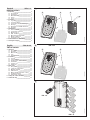
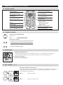
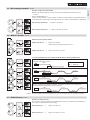
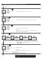
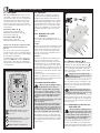
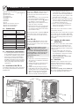
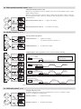
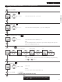
Bedienung und Installation OPERATION AND INSTALLATION Komfort-Funk-Fernbedienung für Durchlauferhitzer* COMFORT RADIO REMOTE CONTROL FOR INSTANTANEOUS WATER HEATER* » FFB 1 SL electronic comfort » FFB 2 SL electronic comfort *DHE 18 SL, DHE 21 SL, DHE 24 SL, DHE 27 SL electronic comfort Best.-Nr. 18 97 76, 18 97 77, 18 97 78, 18 97 79, 22 32 03, 22 32 04 22 32 05, 22 32 06 *DHE 18 SLi, DHE 21 SLi, DHE 24 SLi, DHE 27 SLi electronic comfort Best.-Nr. 18 97 80, 18 97 81, 18 97 82, 18 97 83 279142 Deutsch Inhaltsverzeichnis Inhaltsverzeichnis Seite 3-9 A 1. Bedienung_____________________________________3 1.1 Beschreibung______________________________ 3 1.2 Bedienung_________________________________ 3 1.3 Wandhalterung____________________________ 4 1.4 Pflege_______________________________________ 4 1.5 Pflege_______________________________________ 4 2. Installation_____________________________________5 2.1 Legende_____________________________________ 5 2.2 Technische Daten_________________________ 5 2.3 Vorschriften und Bestimmungen______ 5 2.4 Montage____________________________________ 5 2.5 Abmelden von Funkbedienteilen______ 5 2.6 Übergabe___________________________________ 5 3. Menüführung__________________________________6 3.1 Auf einen Blick____________________________ 6 3.2 Temperatur einstellen____________________ 6 3.3 Warnanzeigen_____________________________ 6 3.4 ECO - Funktion____________________________ 6 3.5 Wassermengenautomatik_______________ 7 3.6 Wellness-Duschen________________________ 7 3.7 Kindersicherung___________________________ 7 4. Komfortfunktionen-Einstellung______________8 5. Störungsbeseitigung__________________________9 English Table is of contents Seite 10-16 FFB 1 SL 1 3 2 electr onic co mf or t 6 C26_02_02_0741 7 B FFB 2 SL 1 1. Operation____________________________________ 10 1.1 Description________________________________ 10 1.2 Operation__________________________________ 10 1.3 Wall mount________________________________ 11 1.4 Care_________________________________________ 11 1.5 Important note___________________________ 11 2. Installation___________________________________ 12 2.1 Legend_____________________________________ 12 2.2 Technical Data____________________________ 12 2.3 Requirements and conditions_________ 12 2.4 Installation________________________________ 12 2.5 Logging out_______________________________ 12 2.6 Hand-over_________________________________ 12 3. Menu guide__________________________________ 13 3.1 At a glance________________________________ 13 3.2 Setting the temperature________________ 13 3.3 Warning displays_________________________ 13 3.4 ECO function______________________________ 13 3.5 Water quantity automatic control_____ 13 3.6 Healthy showering_______________________ 13 3.7 Child safety control______________________ 13 4. Setting the comfort functions______________ 15 5. Troubleshooting_____________________________ 16 2 electr onic co mf or t 6 C26_02_02_0741 7 el ec tr on ic co m fo rt C el ec tro ni c co m fo el ec tr on ic co m fo rt rt el ec tr on ic co m fo rt FFB 1 SL ic comfort C26_02_02_0743 el ec tr on ic co m fo rt el ec tr on ic co m fo rt electron FFB 2 SL für den Benutzer und den Fachhandwerker FFB 1 SL und FFB 2 SL ermöglichen eine Fernbedienung der Durchlauferhitzer DHE .. SL (i) electronic comfort über eine Funkstrecke. Das Gerät lässt sich sowohl über die Funkfernbedienung als auch über das Bedienteil am Gerät bedienen, die Daten werden in beide Richtungen übertragen (siehe auch 1.2 Bedienung). Lieferumfang FFB 1 SL A • Funkbedienteil 1 • Wandhalterung mit Klebepad 2 • Sende- und Empfangsmodul 3 Lieferumfang FFB 2 SL B • Funkbedienteil 1 • Wandhalterung mit Klebepad 2 Die FFB 2 SL arbeitet nur in Verbindung mit dem Sende- und Empfangsmodul der FFB 1 SL. Das Funkbedienteil ist wasserdicht (IPX7) und kann somit auch beim Duschen oder Baden benutzt werden. Die Reichweite des Funkbedienteiles beträgt ca. 25 m im Gebäude. Zusätzlich zum Funkbedienteil der FFB 1 SL können bis zu 5 weitere Funkbedienteile FFB 2 SL mit dem Sende- und Empfangsmodul im Durchlauferhitzer kommunizieren. Das Wichtigste in Kürze Das Funkbedienteil befindet sich im Normal fall im stromsparenden Modus (Display ausgeschaltet). Durch kurzes Drücken einer beliebigen Taste (7) wird das Bedienteil aktiviert, die Hintergrundbeleuchtung erscheint sofort, die Anzeige nach ca. 3 Sekunden. Die Beleuchtung wird bei jeder Tastenbetätigung für 8 Sekunden aktiviert. Erfolgt innerhalb von 30 Sekunden keine Betätigung einer Taste, schaltet das Bedienteil automatisch wieder in den stromsparenden Modus. Funktion Das zuerst betätigte Bedienteil (die Funkfernbedienung oder das Bedienteil am Gerät) erhält Priorität für den nächsten Zapfvorgang, das heißt, von anderen Bedienteilen kann die gewählte Temperatur verringert oder maximal auf 43 °C erhöht werden. Aktivierung Zur Aktivierung des dynamischen Verbrühschutzes muss entweder am DHE..SL (i) für die ausgewählte Zapfstelle eine Temperaturwahl durch Betätigung eines Bedienelementes erfolgen oder an einem Funkbedienteil eine Temperaturwahl durch Drücken einer beliebigen Taste, die das Funkbedienteil „aufweckt“, erfolgen. Im Display des Funkbedienteils erscheint dann die gewählte Solltemperatur, die ggf. noch angepasst werden kann. Beginnt während der nächsten 2 Minuten eine Zapfung, bleibt der dynamische Verbrühschutz während der Zapfung und bis 2 Minuten nach Zapfende erhalten. 26_02_02_0745 Batteriewechsel empfohlen 5 Um die Verbrühgefahr zu reduzieren, ist die Funkfernbedienung mit einem dynamischen Verbrühschutz ausgestattet. • Bei Auslauftemperaturen größer 43 °C besteht Verbrühungsgefahr! M1 Speichertasten – Speichern und Abrufen von 2 Solltemperaturen M2 durch den Benutzer PZ 1 1.2.1Dynamischer Verbrühschutz 1.2.2Wichtige Hinweise Temperaturwahl – zwischen 20 ˚C und 60 ˚C, in 0,5 ˚C-Stufen verstellbar D Deutsch 1.2 Bedienung 1.1 Beschreibung • Sollten Kinder oder Personen mit eingeschränkten physischen, sensorischen oder geistigen Fähigkeiten das Gerät bedienen, so ist sicherzustellen, dass dies nur unter Aufsicht oder nach entsprechender Einweisung durch eine für ihre Sicherheit zuständige Person geschieht. Kinder sollten beaufsichtigt werden, um sicherzustellen, dass sie nicht mit dem Gerät spielen - Verbrühungsgefahr! Ist das nicht zu vermeiden, empfehlen wir eine dauerhafte Temperaturbegrenzung über die Funktion „Kindersicherung“ (siehe Komfortfunktionen-Einstellung). Weitergehender „Verbrühschutz“ kann durch den Fachhandwerker (im Kundendienstmodus am DHE..SL (i)-Bedienteil) aktiviert werden. Alle Informationen in dieser Bedienung und Installationsanleitung müssen beachtet werden. Sie geben wichtige Hinweise für die Sicherheit, und Bedienung der Funkfernbedienung. 9 4 8 C26_02_02_0742 1. Bedienung D 1.2.3Batteriewechsel Das Funkbedienteil wird von 2 Lithiumzellen (Bauform CR123A) versorgt. Erscheint das im Display, wird ein BatterieSymbol wechsel empfohlen. Ansonsten Batterie bei schwacher oder nicht mehr vorhandener Anzeige wechseln. Verbrauchte Batterien unbedingt entfernen. Für Schäden durch ausgelaufene Batterien kann nicht gehaftet werden! Zum Wechseln der Batterien das Gehäuse unterteil (5) aufzuschrauben und beide Batterien (8) tauschen. Auf die korrekte Polung der Batterien achten. Immer gleichartige Batterie typen verwenden und paarweise tauschen. Batterien dürfen nicht im Hausmüll entsorgt werden. Verbrauchte Batterien müssen beim Handel oder einer Sammelstelle für Sonderstoffe abgegeben werden! Bei der Installation des Gehäuseunterteiles ist darauf zu achten, dass die Dichtung (9) korrekt im Gehäuseoberteil (4) liegt, damit die Dichtigkeit des Bedienteils gewährleistet bleibt. 1.2.4Hinweise zur Funkstrecke Spezielle Gegebenheiten in Gebäuden können zu einer Schwächung der Ausbreitung der Funkwellen führen. In solchen Fällen kann die Reichweite der Fernbedienung reduziert sein. Wenn die FFB..SL keine Verbindung zum Gerät aufbauen kann, erscheint in der Anzeige: „CON“ Da der verwendete Frequenzbereich von 868 MHz auch für andere Anwendungen (Funkthermostate, Wetterstationen mit Funk übertragung, Funkkopfhörer etc.) frei zur Verfügung steht, kann es bei zeitgleichem Senden eventuell zu einer Störung der Funkstrecke zum Durchlauferhitzer kommen. Hier besteht kein Risiko, das heißt, es kann nicht zu einer ungewollten Veränderung der Solltemperatur kommen, aber in diesem Fall kann ein gesendeter Temperatursollwert vom Empfänger nicht erkannt werden. In solchen Fällen ist eine Wiederholung der Temperatur-Einstellung notwendig. 1.3 Wandhalterung Die zum Lieferumfang gehörende Wandhalterung kann bei Bedarf vom Benutzer an einem beliebigen Ort zur Aufnahme des Funkbedienteils montiert werden. Dies ist mit dem beiliegendem Klebepad und oder mittels Schrauben möglich. 1.4 Pflege Zur Pflege der Teile genügt ein feuchtes Tuch. Keine scheuernden oder lösenden Reinigungsmittel verwenden. 1.5 Wichtiger Hinweis Die CE-Kennzeichnung der Funk-Fernbedienung FFB..SL dokumentiert die Übereinstimmung mit den grundlegenden Anforderungen – gemäß dem Gesetz über Funkanlagen und Telekommunikationsendeinrichtungen (FTEG) und der Richtlinie 1999/5/EG (R&TTE); – gemäß der Niederspannungsrichtlinie 2006/95/EG; – gemäß der EMV-Richtlinie 2004/108/EG. Diese Anleitung sorgfältig aufbewahren, bei Besitzerwechsel dem Nachfolger aushändigen. Bei etwaigen Instandsetzungsarbeiten ist die Anleitung dem Fachhandwerker zur Einsicht zu überlassen. Einbau des Sende- und Empfangsmoduls und/ oder Erstinbetriebnahme der FFB 1 SL müssen von einem Fachhandwerker unter Beachtung dieser Installtionsanleitung durchgeführt werden. Um eine Verbindung zwischen dem Durchlauferhitzer und dem Funkbedienteil 1 herzustellen, muss zuerst das Sende- und Empfangsmodul 3 der FFB 1 SL installiert werden. Soll der Durchlauferhitzer über mehrere Funkbedienteile bedient werden, können an das eingebaute Sende- und Empfangsmodul bis zu 5 weitere FFB 2 SL-Funkbedienteile angemeldet werden. A - E 1 Funkbedienteil FFB 2 SL 2 Wandhalterung FFB 1 SL 3 Sende- und Empfangsmodul 4 Gehäuseoberteil 5 Gehäuseunterteil 6 Display 7 Tasten 8 Batterien 9 Dichtung 10 Stecker Sende- und Empfangsmodul 11 Taster Sende- und Empfangsmodul 12 LED Sende- und Empfangsmodul 2.2 Technische Daten Funk-Fernbedienung Abmessung (H / B / T) Gewicht ohne Wandhalter Funkstrecke Funkfrequenz Reichweite im Gebäude Temperatur-Einstellbereich Batterie Schutzart FFB 1 SL FFB 2 SL 152 / 85 / 22 mm 190 g bidirektional 868,3 MHz ca. 25 m 20 - 60 ˚C CR123A (2x) IPX5 / IPX7 Tabelle 1 2.3 Vorschriften und Bestimmungen • Die Gebrauchs- und Montageanleitung des Durchlauferhitzers ist bei der Installation und Bedienung zu beachten. • Alle elektrischen Anschluss- und Installa tionsarbeiten sind nach den VDE-Bestimmungen (0100), den Vorschriften des zuständigen EVU’s sowie den entsprechenden nationalen und regionalen Vorschriften auszuführen. 2.4 Montage der FFB..SL Zur Montage der Funkfernbedienung zusätzlich die Gebrauchs- und Montageanleitung des DHE..SL (i) beachten! E 2.4.1FFB 1 SL Zur Inbetriebnahme des FFB 1 SL das Sendeund Empfangsmodul in den Durchlauferhitzer einbauen: ð Durchlauferhitzer spannungsfrei schalten; ð Gerätekappe des Durchlauferhitzers wie in der Geräte-Montageanleitung beschrieben abnehmen; Stecker E (10) des Moduls auf Steckplatz „Adapter“ im Gerät (DHE..SL (i)) stecken. Modul rechts oben in die Geräterückwand einsetzen. Gerätekappe des Durchlauferhitzers montieren und Durchlauferhitzer an Spannung legen (Montageanleitung Durchlauferhitzer beachten!). Für FFB 1 SL sind keine Maßnahmen zur Erstinbetriebnahme nötig, diese Funkfernbedienung funktioniert sofort nach Einbau des Sende- und Empfangsmoduls. 2.4.2FFB 2 SL Zur Aktivierung eines FFB 2 SL-Funkbedienteiles muss dessen Senderkennung zur Erstinbetriebnahme einmal zum Sende- und Empfangsmodul übertragen werden. Bei der Erstinbetriebnahme von FFB 2 SL-Bedienteilen muss der Durchlauferhitzer betriebsbereit sein. Die folgenden Arbeiten müssen unter Spannung erfolgen. Nach Öffnen der Gerätekappe auf spannungsführende Teile achten. Erstinbetriebnahme Gerätekappe des Durchlauferhitzers (siehe Montageanleitung DHE..SL (i)) abnehmen Funkfernbedienung durch Drücken einer beliebigen Taste aktivieren. Im Display erscheint „CON“ Lernmodus durch Drücken der Taste (11) am Sende- und Empfangsmodul (3) aktivieren (aktivierter Lernmodus wird durch die leuchtende LED (12) am Sende- und Empfangsmodul angezeigt). Nach 30 Sekunden ohne Empfang verlässt das Sende- und Empfangsmodul den Lernmodus automatisch (die LED erlischt) Die verbleibende Zeit für den Lernmodus wird durch den rückwärts laufenden Balken im Display des Funkbedienteils angezeigt. Während des Lernmodus nochmals eine beliebige Taste am neuen Funkbedienteil drücken. Die Einstellwerte des Durchlauferhitzers werden auf dem Display des Funkbedienteils angezeigt. Als Bestätigung des Lernvorganges blinkt kurz die LED. Gerätekappe des Durchlauferhitzers wieder montieren (Montageanleitung des Durchlauferhitzer beachten!). Weitere Funkbedienteile werden in gleicher Weise in Betrieb genommen. Werden mehrere Funkbedienteile nacheinander angemeldet, ist die Taste (11) zur Aktivierung des Lernmodus in dem Sende- und Empfangsmodul für jedes Funkbedienteil neu zu drücken. 2.5 Abmelden von Funkbedienteilen Wird aus einer bestehenden Anlage (ein Durchlauferhitzer mit mehreren Funkbedienteilen) ein Funkbedienteil entfernt, ist folgende Vorgehensweise aus Sicherheitsgründen erforderlich: Die Taste (11) am Sende- und Empfangsmodul 5 Sekunden gedrückt halten, bis die rote LED blinkt. Damit wird der Speicher für alle Senderkennungen gelöscht; verbleibende Funkbedienteile neu anmelden (siehe 2.4.2). 2.6 Übergabe Erklären Sie dem Benutzer die Funktionen des Gerätes. Machen Sie ihn besonders auf die Sicherheitshinweise aufmerksam. Überreichen Sie dem Benutzer die Bedienungsund Installtionsanleitung. Aussagen zu: „Umwelt, Recycling, Kundendienst und Garantie“ siehe Gebrauchs- und Montageanleitung Durchlauferhitzer. DHE .. SL (i) 12 Adapter 10 11 C26_02_02_0596_c 2.1 Legende Deutsch für den Fachhandwerker 26_02_02_0597_c 2. Installation 3. Menüführung für den Benutzer und den Fachhandwerker 3.1 Auf einen Blick Temperatur-Anzeige Batteriewechsel wird empfohlen Balkenanzeige der Leistung Error / Fehleranzeige (siehe Kundendienstmodus am Gerät) Zweite Anzeige z. B. Durchflussmenge Hintergrundbeleuchtung Temperatur-Speichertasten Anzeige Symbole: M1 und M2 - ECO - Wellness-Duschen Menütaste - Wassermengenautomatik Kindersicherung - Kindersicherung Wellnessprogramme ECO Wasser und Energiesparen Wassermengenautomatik Temperaturwahl (Werte einstellen) 3.2 Temperatur einstellen stufenlose Temperaturwahlmöglichkeit l 20 bis 60 °C l OFF ð Heizung ist ausgeschaltet. Temperatur-Speichertasten für schnellen Wechsel zwischen zwei vorgewählten Temperaturen l 2 Sekunden drücken zum Speichern der Wunschtemperatur: Temperatur-Anzeige blinkt 1 x auf und wird gespeichert. l gespeicherte Temperatur wählen 3.3 Warnanzeigen electronic comfort Warnblinker bei Übertemperatur Wenn die Einlauftemperatur größer als die Wunschtemperatur ist, z. B. in Verbindung mit vorgewärmtem Solarwasser, blinkt die Temperatur-Anzeige und die zweite Anzeige zeigt die Einlauftemperatur an. Temperatur-Anzeige blinkt Zweite Anzeige Einlauftemperatur 3.4 ECO - Funktion Ein/Aus ECO Funktion zum Wasser und Energiesparen Die durchfließende Wassermenge wird auf einen Maximalwert begrenzt (Werkeinstellung 8 l/min, ein anderer Wert kann im Menü eingestellt werden). Veränderung des Maximalwertes siehe Punkt „4. Komfortfunktionen-Einstellungen“. ECO ECO ein ð Symbol in der Anzeige ECO aus ð Symbol in der Anzeige erlischt ECO 3.5 Wassermengenautomatik Ein/Aus Wird die vorgewählte Füllmenge erreicht, reduziert die Automatik die Durchflussmenge auf ca. 4 l/min. Beispiel: Wannenfüllung 80 l. Sind 80 l erreicht, wird auf ca. 4 l/min reduziert, es läuft nur noch wenig Wasser zu. Die Wunschtemperatur bleibt konstant. Veränderung der Max. Wassermenge siehe Punkt „4. Komfortfunktionen-Einstellung“. Wassermengenautomatik ein ð Symbol in der Anzeige Wassermengenautomatik aus ð Symbol in der Anzeige erlischt 3.6 Wellness-Duschen Ein/Aus Wellness-Dusch-Programme wählen. Wellness-Duschen ein ð Symbol in der Anzeige dabei Anzeige des Duschprogrammes für 2 sec. 2 sec Wellness-Duschen aus ð Symbol in der Anzeige erlischt 2 sec 4 verschiedene Wellness-Dusch-Programme für Wechselduschen können gewählt werden. Zur Abhärtung ist der Abschluss mit einer Kaltdusche empfohlen, damit der Körper eine reflexartige Erwärmung einleitet. WW = Warmwasser 3 min WW KW = Kaltwasser KW Erfrischender Abschluss einer Winterdusche mit Wiedererwärmung. 3 min 10 sec 10 sec WW WW - 10 °C 10 sec 10 sec Die schnelle Wechseldusche zur Steigerung der Fitness mit abschließender Wiedererwärmung. 3 min 10 sec 10 sec WW 10 sec 10 sec KW Zur Förderung der Durchblutung werden Arme und Beine kalt abgeduscht. Dabei soll das Duschen - beginnend von Händen und Füßen - zum Körper hin erfolgen. Der Vorgang kann anschließend mit warmem Wasser wiederholt werden. 3 min 30 sec 30 sec WW 20 sec 20 sec KW Hinweis: Das zuletzt gewählte Duschprogramm wird bei erneuter Betätigung der Taste automatisch gewählt. 3.7 Kindersicherung Ein/Aus Einstellen der Kindersicherung Die einstellbare Temperatur wird auf einen Maximalwert begrenzt. Veränderung des Maximalwertes siehe Punkt „4. Komfortfunktionen-Einstellung“. Kindersicherung ein ð Symbol in der Anzeige Kindersicherung aus ð Symbol in der Anzeige erlischt Deutsch Einstellen der Wassermengenautomatik 4. Komfortfunktionen-Einstellung für den Benutzer und den Fachhandwerker START 2 Sekunden drücken Energie- und Wassersparen 4 - 15 l/min Max. Wert für Durchflussbegrenzung einstellen, z. B. 8,0 l/min. 20 - 60 °C Max. Wert für Temperaturbegrenzung einstellen, z. B. 36 °C für ein Babybad. Kindersicherung Wassermengenautomatik Max. Wert für Wassermenge einstellen, z. B. 80 l. 5 - 200 l Hinweis: Die Aktivierung der Wassermengenautomatik muss vor der Wannenfüllung erfolgen. Die Aktivierung gilt für eine Wannenfüllung! Zweite Anzeige Durchflussmenge Wassermenge Energieverbrauch Uhr kWh Hinweis: In den Menüs „kWh“ und „m³“ können die Zähler durch gleichzeitiges längeres Drücken und auf NULL zurückgestellt werden. von Uhrzeit einstellen 00:00 ... 23:59 Einstellen der Uhrzeit. Anmerkung: Nach Netzunterbrechung des DHE..SL (i) neu einstellen. 2 Sekunden drücken ð an jeder beliebigen Stelle ð automatisch nach 10 Sekunden der letzten Einstellung. Hinweis: Ende und 2 Sekunden drücken ð Rücksetzung zur Werkseinstellung Störung Ursache Behebung Temperaturen > 43 °C nicht einstellbar Dynamischer Verbrühschutz aktiv Dynamischer Verbrühschutz wird automatisch 2 Minuten nach Zapfende aufgehoben Durchlauferhitzer reagiert nicht, schwache Displayanzeige am Funkbedienteil Niedrige Batteriespannung Batterien am Funkbedienteil wechseln Permanente „CON“-Anzeige am Funkbedienteil Funkbedienteil nicht am Gerät angemeldet Fachhandwerker: Deutsch 5. Störungsbeseitigung Funkfernbedienung für den Benutzer und den Fachhandwerker Funkbedienteil anmelden Bedienteil außerhalb der Reichwei- Abstand des Funkbedienteils zum Gerät verringern te der Sende- und Empfangsbaugruppe Sende- und Empfangsbaugruppe nicht korrekt am Gerät angeschlossen Fachhandwerker: Steckverbindung der Sende- und Empfangsbaugruppe zum Gerät überprüfen Tabelle 2 1. Operation for the user and qualified installer 1.2 Operation 1.1 Description FFB 1 SL and FFB 2 SL allow remote control of the DHE .. SL (i) electronic comfort instantaneous water heater via a line-of-sight radio link. The instantaneous water heater can be operated both from the remote control and from the control unit on the heater and data can be transmitted in both directions (see also 1.2 Operation). Included in FFB 1 SL A • Radio remote control unit 1 • Wall mount with adhesive pad 2 • Transceiver module 3 The radio remote control unit is normally in power save mode (display switched off). Briefly pressing any button (7) activates the control unit; the backlighting comes on immediately and the display appears after approx. 3 seconds. Whenever a button is pressed the lighting comes on for 8 seconds. If no other button is pressed within 30 seconds the unit automatically switches back to power save mode. D PZ 1 1.2.1 Dynamic anti-scald protection Included in FFB 2 SL B • Radio remote control 1 • Wall mount with adhesive pad 2 5 To reduce the risk of scalding, the radio remote control is fitted with dynamic anti-scald protection. Function The first control unit that is activated (the radio remote control unit or the control unit on the heater) is given priority for the next tap procedure, i.e. the selected temperature can be lowered or increased to a maximum of 43 °C from other control units. In addition to the remote control unit belonging to the FFB 1 SL, another 5 FFB 2 SL radio remote control units can communicate with the transceiver module in the instantaneous water heater. To activate the dynamic anti-scald protection, either a temperature must be selected by activating a control on the DHE…SL (i) for the particular water tap, or a temperature must be selected on a radio remote control unit by pressing any button to “wake up” the unit. The remote control unit display then shows the set temperature selected, which can still be adjusted if required. The main information in brief 1.2.2Important information • There is a risk of scalding at outlet temperatures in excess of 43 °C! 26_02_02_0745 M1 Memory push-buttons – 2 reference temperatures can be stored and M2 called up by the user Battery change recommended 10 4 8 Activation If a tap procedure is started within the next 2 minutes, the dynamic anti-scald protection is retained while the tap is running and for up to 2 minutes after it has stopped. Temperature selection – between 20 °C and 60 °C in increments of 0.5 °C 9 • If children or people with restricted physical, sensory or mental capacities use the heater, make sure that they only do so under supervision or after appropriate instruction by a person who is responsible for their safety. Children should be supervised to ensure that they do not play with the heater. Risk of scalding! If it cannot be avoided, we recommend permanently limiting the temperature with the “Child safety control” (see comfort functions setting). Further “anti-scald protection” can be activated by the qualified installer (in service mode on the DHE…SL (i) control unit). All information in these operating and installation instructions must be followed carefully. They contain important information regarding the safety and operation of the radio remote control system. C26_02_02_0742 The FFB 2 SL only works in conjunction with the transceiver module belonging to the FFB 1 SL The remote control unit is watertight (IPX7) and can therefore even be used while taking a shower or bath. It has a range of approximately 25 m within the building. 1.2.3Battery change D The radio remote control unit is powered by 2 lithium cells (type CR123A). When the symbol appears on the display a battery change is recommended. Otherwise change the batteries when the display becomes weaker or is no longer visible. Always take out used batteries. No liability can be accepted for damage caused by dead batteries! To change the batteries, unscrew the back of the casing (5) and replace both batteries (8). Note the correct position of the battery poles. Always use the same type of battery and replace them in pairs. Batteries must not be disposed of with domestic rubbish. Used batteries must be taken back to the shop or a collection point for special substances! When replacing the back of the casing, make sure that the seal (9) is placed correctly in the front of the casing (4) so that the control unit remains sealed. 1.2.4Information on the line-ofsight radio link Special conditions in buildings may weaken the propagation of the radio waves. In these cases the range of the remote control may be reduced. If the FFB..SL cannot establish a connection with the heater, “CON” will appear on the display. Because the 868 MHz frequency range used is also freely available for other applications (radio controlled thermostats, weather stations with radio transmission, radio head-sets, etc.), 1.3 Wall mount If required by the user, the wall mount supplied can be fitted in any location to hold the radio remote control unit. It can be fitted with the adhesive pad supplied or with screws. 1.4 Care A damp cloth is all that is needed to care for the parts. Do not use any abrasive or solventtype cleaning agents. 1.5 Important note The CE marking on the FFB..SL radio remote control registers compliance with the basic requirements – according to the law on radio systems and telecommunication equipment (FTEG) and Directive 1999/5/EG (R&TTE); – according to the Low Voltage Directive 2006/95/EG; – according to the EMC Directive 2004/108/EG. Keep these instructions safe and if the water heater changes hands give to the new owner. If any servicing work is performed, the instructions should be given to the qualified installer to read. Installation of the transceiver module and/or first start-up of the FFB 1 SL must be performed by a qualified installer in accordance with these installation instructions. To establish a connection between the instantaneous water heater and the radio remote control unit 1 , the FFB 1 SL’s transceiver module 3 must be installed first. If the instantaneous water heater is to be operated from several radio remote control units, up to 5 further FFB 2 SL radio remote control units can be logged into the transceiver module installed. 11 English simultaneous transmission may cause a fault in the line-of-sight radio link to the instantaneous water heater. No risk is involved, i.e. the set temperature cannot be changed unintentionally, but the set temperature transmitted will not be recognized by the receiver. In these cases the temperature setting will have to be repeated. 2. Installation for the qualified installer A - E 1 Radio remote control unit FFB 2 SL 2 Wall mount FFB 1 SL 3 Transceiver module 4 Housing top 5 Housing bottom 6 Display 7 Buttons 8 Batteries 9 Seal 10Transceiver module connector 11Transceiver module button 12Transceiver module LED 2.2 Technical data Radio remote control Dimensions (H / W / D) Weight excluding wall mount Line-of-sight radio link Radio frequency Range inside the building Temperature setting range Battery Protection class FFB 1 SL FFB 2 SL 152 / 85 / 22 mm 190 g Two-way 868.3 MHz Approx. 25 m 20 – 60 °C CR123A (2x) IPX5 / IPX7 Table 1 2.3 Requirements and conditions • The operating and installation instructions for the instantaneous water heater should be followed for installation and operation. • All electrical connection and installation work should be performed in accordance with VDE specifications (0100), the requirements of the relevant electricity companies and corresponding national and regional requirements. 2.4 Installation of the FFB..SL To install the radio remote control, also follow the operating and installation instructions for the DHE..SL (i). To start-up the FFB 1 SL, install the transceiver module in the instantaneous water heater: ð Disconnect the water heater from the electricity supply; ð Remove the heater’s cover as described in the heater installation instructions; Insert the module’s connector E (10) into the “Adapter” socket on the heater (DHE..SL (i)). Place the module in the top right of the heater’s back wall. Fit the water heater cover and connect the water heater to a voltage supply (Follow the installation instructions for the instantaneous water heater). No first start-up work is required for FFB 1 SL as this radio remote control is operational as soon as the transceiver module has been fitted. 2.4.2FFB 2 SL To activate an FFB 2 SL radio remote control, its transmission ID must be sent once to the transceiver module so that it can be started up for the first time. When starting-up FFB 2 SL remote control units for the first time the instantaneous water heater must be ready for operation. The following work must be performed while it is connected to the electricity supply. Beware of live parts when opening the heater cover. First start-up Remove the cover from the instantaneous water heater (see installation instructions for DHE..SL (i)) Activate radio remote control by pressing any button. “CON” will appear on the display. Activate learning mode by pressing the button (11) on the transceiver module (3) (learning mode active is shown by the LED (12) on the transceiver module lighting). After 30 seconds without receiving, the transceiver module automatically leaves 12 learning mode (LED goes out). The remaining learning mode time is shown by the bar, running backwards, on the remote control unit’s display. While in learning mode, again press any key on the new radio remote control unit. The values set for the instantaneous water heater are shown on the radio remote control unit’s display. The LED flashes briefly to confirm the learning process. Put the cover back on the instantaneous water heater (follow the installation instructions for the heater). Other radio remote control units are commissioned in the same way. If several radio remote control units are logged in one after the other, the button (11) should be pressed again for each radio remote control unit to activate learning mode in the transceiver module. 2.5Logging out radio remote control units If a radio remote control unit is removed from an existing system (one instantaneous water heater with several radio remote control units), the following procedure is required for safety reasons: Keep the button (11) on the transceiver module pressed down for 5 seconds until the red LED flashes. This deletes all transmitter IDs from the memory; Log the remaining radio remote control units back in (see 2.4.2). 2.6 Hand-over Explain the device’s functions to the user. In particular draw his attention to the safety instructions. Give the user the operating and installation instructions. Information on: “Environment, recycling, service and warranty” see the operating and installation instructions for the instantaneous water heater. DHE .. SL (i) 26_02_02_0597_c E 2.4.1FFB 1 SL 12 Adapter 10 11 C26_02_02_0596_c 2.1 Legend 3. Menu guide for the user and qualified installer 3.1 At a glance Temperature display Battery change recommended Bar display to indicate power Error display (see service mod on the water heater) Second display Temperature memory buttons Display symbols: M1 and M2 - ECO English Backlighting e.g. flow quantity -Healthy showering Menu button - Water quantity automatic control Child safety control - Child safety control Wellness programme ECO water and energy saver Water quantity automatic control Temperature selection (set values) 3.2 Setting the temperature Stepless adjustable temperature selection l 20 to 60 °C l OFF ð Heating is switched off Temperature memory push-buttons For rapid switching between two pre-selected temperatures l Press for 2 seconds to save the required temperature: Temperature display flashes once and is saved. l Select stored temperature 3.3 Warning displays electronic comfort Flashing warning light for excess temperature When the inlet temperature is higher than the desired temperature, e.g. as a result of solar-heated water, the temperature display flashes and the second display shows the inlet temperature. Temperature display flashes Second display – inlet temperature 3.4 ECO function On/Off ECO function for water and energy saving The quantity of water flowing through is limited to a maximum value (factory setting 8 l/min, a different value can be set in the menu). ECO ECO on ð Symbol in the display ECO off ð Symbol disappears ECO 13 3.5 Water quantity automatic control On/Off Setting water quantity automatic control When the pre-set quantity is reached the automatic unit reduces the flow quantity to approx. 4 l/min. Example: filling a bath 80 l. When 80 l is reached the flow is reduced to approx. 4 l/min, only a little water continues to flow. The desired temperature remains constant. For changing the max. water quantity see point „4. Setting the comfort functions“. Water quantity automatic control on ð Symbol in the display Water quantity automatic control off ð No symbol in the display 3.6 Healthy showering On/Off Selecting a wellness programme. Healthy showering on ð Symbol in the display The shower programme is shown for 2 s. 2 sec Healthy showering off ð No symbol in the display 2 sec 4 different wellness shower programmes can be selected for alternate showering To harden your body you are advised to end with a cold shower, so that the body initiates a reflex action to warm itself up. WW = Warm water 3 min WW KW = Cold water KW Stimulating end to a winter shower with re-warming 3 min 10 sec WW WW - 10 °C 10 sec 10 sec 10 sec Rapid alternate showers to increase fitness, ending with re-warming 3 min 10 sec 10 sec WW 10 sec 10 sec KW Arms and legs are showered in cold water to promote circulation. Showering – beginning with hands and feet – should be directed towards the body. The process can then be repeated with warm water. 3 min 30 sec 30 sec WW 20 sec 20 sec KW Note: The last shower programme selected is automatically selected again the next time a button is pressed. 3.7 Child safety control On/Off Setting the child safety control The variable temperature is restricted to a maximum value. See point „4. Setting the comfort functions” on changing the maximum value. Child safety control on ð Symbol in the display Child safety control off ð 14 No symbol in the display 4. Setting the comfort functions for the user and the qualified installer START Press for 2 seconds Energy and water saving Set the max. flow rate value, e.g. 8.0 l/min. 20 - 60 °C Set the max. value to limit temperature, e.g. 36 °C for a baby’s bath. English 4 - 15 l/min Child safety control Water quantity automatic control Set the max. value for water quantity, e.g. 80 l. 5 - 200 l Note: The water quantity automatic control must be operated before filling the bath. Operation applies for one filling of the bath only. Second display Flow rate Water quantity Energy consumption Time kWh Note: In the “kWh” and “m3” menus, the meters can be reset to ZERO by pressing and holding and together. down Setting the clock 00:00 ... 23:59 Set the clock Remark: Re-set after a power cut affecting the DHE..SL (i) Press for 2 seconds ð at any point ð Automatically 10 seconds after the last setting Note: End Press und for 2 seconds à return to factory settings 15 5. Troubleshooting on the radio remote control for the user and the qualified installer Fault Cause Temperatures cannot be set > 43 °C Dynamic anti-scald protection is on Dynamic anti-scald protection goes off automatically 2 minutes after the end of drawing water The instantaneous water heater is Low batteries not responding, weak display on the radio remote control unit “CON” permanently displayed on Radio remote control unit not the radio remote control unit logged into the heater Table 2 16 Remedy Change batteries in the radio remote control unit Qualified installer: Log in the radio remote control unit Remote control unit is out of the transceiver module’s range Reduce the distance between the radio remote control unit and the heater Transceiver module not correctly connected to the heater Qualified installer: check the connection of the transceiver module to the heater English Notizen / Notes 17 Notizen / Notes 18 Notizen / Notes 19 Verkauf Tel. 0180 3 700705 | Fax 0180 3 702015 | [email protected] Kundendienst Tel. 0180 3 702020 | Fax 0180 3 702025 | [email protected] Ersatzteilverkauf Tel. 0180 3 702030 | Fax 0180 3 702035 | [email protected] Vertriebszentren Tel. 0180 3 702010 | Fax 0180 3 702004 Austria STIEBEL ELTRON Ges.m.b.H. Eferdinger Str. 73 | A-4600 Wels Tel. 072 42-47367-0 | Fax 07242-47367-42 Email [email protected] www.stiebel-eltron.at Great Britain Applied Energy Products Ltd. Morley Way | GB-Peterborough PE2 9JJ Tel. 087 09-00 04 20 | Fax 017 33-31 96 10 Email [email protected] www.applied-energy.com Sweden STIEBEL ELTRON AB Friggagatan 5 | SE-641 37 Katrineholm Tel. 0150-48 7900 | Fax 0150-48 7901 Email [email protected] www.stiebel-eltron.se Belgium STIEBEL ELTRON Sprl / Pvba P/A Avenue du Port 104, 5 Etage B-1000 Bruxelles Tel. 02-4232222 | Fax 02-4232212 Email [email protected] www.stiebel-eltron.be Hungary STIEBEL ELTRON Kft. Pacsirtamezo´´ u. 41 | H-1036 Budapest Tel. 012 50-6055 | Fax 013 68-8097 Email [email protected] www.stiebel-eltron.hu Switzerland STIEBEL ELTRON AG Netzibodenstr. 23 c | CH-4133 Pratteln Tel. 061-8 16 93 33 | Fax 061-8 16 93 44 Email [email protected] www.stiebel-eltron.ch Czech Republik STIEBEL ELTRON spol. s r.o. K Hájům 946 | CZ-15500 Praha 5-Stodůlky Tel. 2-511 16111 | Fax 2-355 12122 Email [email protected] www.stiebel-eltron.cz Netherlands STIEBEL ELTRON Nederland B.V. Daviottenweg 36 | Postbus 2020 NL-5202 CA‘s-Hertogenbosch Tel. 073-6 23 00 00 | Fax 073-6 23 11 41 Email [email protected] www.stiebel-eltron.nl Thailand STIEBEL ELTRON Asia Ltd. 469 Moo 2, Tambol Klong-Jik Ampur Bangpa-In | Ayutthaya 13160 Tel. 035-22 00 88 | Fax 035-22 11 88 Email [email protected] www.stiebeleltronasia.com Denmark PETTINAROLI A/S Madal Allé 21 | DK-5500 Middelfart Tel. 63 41 66 66 | Fax 63 41 66 60 Email [email protected] www.pettinaroli.dk Poland STIEBEL ELTRON sp.z. o.o ul. Instalatorów 9 | PL-02-237 Warszawa Tel. 022-8 46 48 20 | Fax 022-8 46 67 03 Email [email protected] www.stiebel-eltron.com.pl United States of America STIEBEL ELTRON Inc. 17 West Street | West Hatfield MA 01088 Tel. 4 13-247-3380 | Fax 413-247-3369 Email [email protected] www.stiebel-eltron-usa.com France STIEBEL ELTRON S.A.S. 7-9, rue des Selliers B.P. 85107 | F-57073 Metz-Cédex 3 Tel. 03 87 74 38 88 | Fax 03 87 74 68 26 Email [email protected] www.stiebel-eltron.fr Russia STIEBEL ELTRON RUSSIA Urzhumskaya street, 4. | 129343 Moscow Tel. (495) 775 3889 | Fax (495) 775-3887 Email [email protected] www.stiebel-eltron.ru Irrtum und technische Änderungen vorbehalten | Subject to errors and technical changes! | Sous réserve d‘erreurs et de modifications techniques! · Onder voorbehoud van vergissingen en technische wijzigingen! | Salvo error o modificación técnica! | Rätt till misstag och tekniska ändringar förbehålls! | Excepto erro ou alteração técnica | Zastrzeżone zmiany techniczne i ewentualne błędy | Omyly a technické změny jsou vyhrazeny! | A muszaki változtatások és tévedések jogát fenntartjuk! | Âîçìîæíîñòü íåòî÷íîñòåé è òåõíè÷åñêèõ èçìåíåíèé íå èñêëþ÷àåòñÿ 8268 CAP 279142-34590-2-8276 · HD Deutschland STIEBEL ELTRON GmbH & Co. KG Dr.-Stiebel-Straße | D-37603 Holzminden Tel. 0 55 31 702 0 | Fax 0 55 31 702 480 Email [email protected] www.stiebel-eltron.de


![SS HNBL-018 Owners manual HN1004-5 [EN] A3.indd - Jouef](http://vs1.manualzilla.com/store/data/006909007_1-61f91df4c9e84909195a3d6de9b86041-150x150.png)