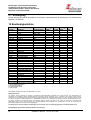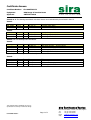
1
Bedienungs- und Installationsanleitung Installation- and Operation Instruction Gasentnahmesonden / Sample Gas Probes Baureihe / Serie 222.xx ATEX Lesen Sie die Bedienungsanleitung vor dem Gebrauch des Gerätes gründlich durch, insbesondere die Hinweise unter Gliederungspunkt 2. Andernfalls könnten Gesundheits- oder Sachschäden auftreten. Die Bühler Technologies GmbH haftet nicht bei eigenmächtigen Änderungen des Gerätes oder für unsachgemäßen Gebrauch. Read this instruction carefully prior to installation and/or use. Pay attention particularly to all advises and safety instructions to prevent injuries. Bühler Technologies GmbH can not be held responsible for misusing the product or unreliable function due to unauthorised modifications. BX460012, 09/2012 Art. Nr. 90 31 042 Bühler Technologies GmbH, Harkortstr. 29, D-40880 Ratingen Tel. +49 (0) 21 02 / 49 89-0, Fax. +49 (0) 21 02 / 49 89-20 Internet: www.buehler-technologies.com Email: [email protected] 1 Bedienungs- und Installationsanleitung Installation- and Operation Instruction Gasentnahmesonden / Sample Gas Probes Baureihe / Serie 222.xx ATEX Inhaltsverzeichnis Seite 1 Einleitung ........................................................................................................................... 4 2 Wichtige Hinweise ............................................................................................................. 4 2.1 Allgemeine Gefahrenhinweise ...........................................................................................................6 3 Erläuterungen zum Typenschild....................................................................................... 9 4 Produktbeschreibung........................................................................................................ 9 4.1 4.2 4.3 Allgemeine Beschreibung ..................................................................................................................9 Anwendungsbereich ........................................................................................................................10 Lieferumfang ...................................................................................................................................11 5 Transport und Lagerungsvorschriften ........................................................................... 12 6 Aufbauen und Anschließen............................................................................................. 12 6.1 Montage ...........................................................................................................................................12 6.2 Anschluss der Gasleitungen ............................................................................................................13 6.3 Anschluss der Rückspülung und des Druckgasbehälters (für GAS 222.35 ATEX, 31 ATEX und 21 ATEX) .....................................................................................................................................................14 6.4 Elektrische Anschlüsse ...................................................................................................................15 7 7.1 7.2 7.3 7.4 7.5 7.5.1 7.5.2 7.6 Betrieb und Wartung ....................................................................................................... 17 Warnhinweise ..................................................................................................................................18 Vor Inbetriebnahme .........................................................................................................................20 Sonde GAS 222.20 ATEX ...............................................................................................................21 Sonden GAS 222.35, 31 ATEX und 21 ATEX .................................................................................22 Rückspülung des Eintrittsfilters (im Prozessstrom) .........................................................................23 Manuelle Rückspülung ................................................................................................................23 Automatische Rückspülung .........................................................................................................23 Wartungsplan ..................................................................................................................................24 8 Fehlersuche und Beseitigung......................................................................................... 25 9 Instandsetzung und Entsorgung .................................................................................... 25 9.1 Entsorgung ......................................................................................................................................26 10 Beständigkeitsliste .......................................................................................................... 26 11 Betriebstagebuch (Kopiervorlage) ................................................................................. 27 12 Angehängte Dokumente.................................................................................................. 28 2 BX460012, 09/2012 Art. Nr. 90 31 042 Bedienungs- und Installationsanleitung Installation- and Operation Instruction Gasentnahmesonden / Sample Gas Probes Baureihe / Serie 222.xx ATEX Contents page 1 Introduction ..................................................................................................................... 29 2 Important advices ............................................................................................................ 29 2.1 General indication of risk .................................................................................................................30 3 Explanation of the type plate .......................................................................................... 33 4 Product description ......................................................................................................... 33 4.1 4.2 4.3 General description .........................................................................................................................33 Field of application ...........................................................................................................................34 Included items in delivery ................................................................................................................35 5 Transport and storing regulations ................................................................................. 36 6 Installation and connection ............................................................................................ 36 6.1 6.2 6.3 6.4 7 7.1 7.2 7.3 7.4 7.5 7.5.1 7.5.2 7.6 Mounting ..........................................................................................................................................36 Tube Fittings ....................................................................................................................................37 Connection of the blow back line and the pressure vessel (for GAS 222.21 ATEX, 31 ATEX and 35 ATEX) ..................................................................................................................................38 Electrical connections ......................................................................................................................39 Operation and Maintenance ............................................................................................ 41 Indication of risk...............................................................................................................................42 Check before operation ...................................................................................................................44 Probe type GAS 222.20 ATEX ........................................................................................................45 Probe types GAS 222.35 ATEX, 31 ATEX and 21 ATEX ...............................................................46 Blow back of the in-situ filter (inside the process) ...........................................................................47 Manual blow back ........................................................................................................................47 Automatic blow back ...................................................................................................................47 Maintenance program......................................................................................................................48 8 Trouble shooting ............................................................................................................. 49 9 Repair and disposal ........................................................................................................ 49 9.1 Disposal ...........................................................................................................................................49 10 List of chemical resistance ............................................................................................. 50 11 Maintenance book (Please make copies) ...................................................................... 51 12 Attached documents ....................................................................................................... 52 BX460012, 09/2012 Art. Nr. 90 31 042 3 Bedienungs- und Installationsanleitung Installation- and Operation Instruction Gasentnahmesonden / Sample Gas Probes Baureihe / Serie 222.xx ATEX 1 Einleitung Die Gasentnahmesonden der Baureihe GAS 222.xx-Atex sind zum Einbau in Gasanalysesystemen für industrielle Anwendungen geeignet. Gasentnahmesonden gehören zu den wichtigsten Bauteilen eines Gasaufbereitungssystems. Bitte beachten Sie deshalb auch die dazugehörigen Zeichnungen im Datenblatt am Ende dieser Anleitung und überprüfen Sie vor Einbau der Gasentnahmesonden, ob die genannten technischen Daten den Anwendungsparametern entsprechen. Überprüfen Sie ebenfalls, ob alle zum Lieferumfang gehörenden Teile vollständig vorhanden sind. Diese Bedienungsanleitung beschreibt mehrere Sondentypen aus der GAS 222.xx Atex ± Reihe zusammen, da viele Beschreibungen gleich oder ähnlich sind (siehe Kap. 4.1). Welche Sonde Sie vor sich haben, ersehen Sie aus dem Typenschild. Auf diesem finden Sie neben der Seriennummer auch die Artikelnummer und Typbezeichnung. Sofern für einen Sondentyp Besonderheiten gelten, sind diese in der Bedienungsanleitung gesondert beschrieben. Bitte beachten Sie beim Anschluss die Kennwerte der Sonde und bei Ersatzteilbestellungen die richtigen Ausführungen 2 Wichtige Hinweise Der Einsatz der Geräte ist nur zulässig, wenn: - das Produkt unter den in der Bedienungs- und Installationsanleitung beschriebenen Bedingungen, dem Einsatz gemäß Typenschild und für Anwendungen, für die es vorgesehen ist, verwendet wird. - die im Datenblatt und der Anleitung angegebenen Grenzwerte eingehalten werden. - das Gerät beständig gegenüber einwirkenden Medien ist (siehe auch Kapitel 10). - Überwachungsvorrichtungen/ Schutzvorrichtung korrekt angeschlossen sind. - die Service- und Reparaturarbeiten, die nicht in dieser Anleitung beschrieben sind, von Bühler Technologies GmbH durchgeführt werden. - Originalersatzteile verwendet werden. Diese Bedienungsanleitung ist Teil des Betriebsmittels. Der Hersteller behält sich das Recht vor, die Leistungs-, die Spezifikations- oder die Auslegungsdaten ohne Vorankündigung zu ändern. Bewahren Sie die Anleitung für den späteren Gebrauch auf. Begriffsbestimmungen für Warnhinweise: Hinweis Signalwort für wichtige Information zum Produkt auf die im besonderen Maße aufmerksam gemacht werden soll. Vorsicht Signalwort zur Kennzeichnung einer Gefährdung mit geringem Risiko, die zu einem Sachschaden oder leichten bis mittelschweren Körperverletzungen führen kann, wenn sie nicht vermieden wird. Warnung Signalwort zur Kennzeichnung einer Gefährdung mit mittlerem Risiko, die möglicherweise Tod oder schwere Körperverletzungen zur Folge hat, wenn sie nicht vermieden wird. Gefahr Signalwort zur Kennzeichnung einer Gefährdung mit hohem Risiko, die unmittelbar Tod oder schwere Körperverletzung zur Folge hat, wenn sie nicht vermieden wird. 4 BX460012, 09/2012 Art. Nr. 90 31 042 Bedienungs- und Installationsanleitung Installation- and Operation Instruction Gasentnahmesonden / Sample Gas Probes Baureihe / Serie 222.xx ATEX Warnung vor einer allgemeinen Gefahr Warnung vor explosionsgefährdeten Bereichen Netzstecker ziehen Warnung vor elektrischer Spannung Warnung vor Explosionsgefahr Atemschutz tragen Warnung vor dem Einatmen giftiger Gase Warnung vor heißer Oberfläche Gesichtsschutz tragen Warnung vor ätzenden Flüssigkeiten Handschuhe tragen HINWEIS Die Geräte sind für den Einsatz in explosionsgefährdeten Bereichen zugelassen. Beachten Sie die nationalen Vorschriften für das Errichten elektrischer Anlagen in explosionsgefährdeten Bereichen; in Deutschland: - EN 60079-',19'(7Ä(UULFKWHQHOHNWULVFKHU$QODJHQLQH[SORVLRQVJHIlKUGeten %HUHLFKHQ³ - EN 61241-14 ',19'(7Ä(OHNWULVFKH%HWULHEVPLWWHO]XU9HUZHQGXQJLQ%HUHLFKHQPLW brennbarem Staub, Auswahl und Errichtung. - (OH[9Ä9HURUGQXQJEHUHOHNWULVFKH$QODJHQLQH[SORVLRQVJHIlKUGHWHQ5lXPHQ³ - Im Ausland sind die entsprechenden Landesvorschriften zu beachten. HINWEIS Bei Einsatz in explosionsgefährdeten Bereichen: Alle Sondentypen sind in der Grundversion für den Einsatz in explosionsgefährdeten Bereichen der Zone 1 und 21 geeignet. Je nach gewähltem Zubehör (z.B. Anbauteile wie Magnetventile, beheizter Rückspülbehälter...) kann der zugelassene Einsatzbereich stark eingeschränkt sein. Bei Verwendung von Kategorie 3G und / oder 3D Zubehör ist der Einsatzbereich der Sonden auf die Zone 2 und / oder Zone 22 beschränkt. Beachten Sie daher unbedingt die Typenschilder aller Anbauteile. Insbesondere ist auf die Zündschutzkennzeichnung der Anbauteile und alle Gefahrenhinweise in dieser Anleitung zu achten. Beachten Sie auch beiliegende Bedienungsanleitungen der Anbauteile. BX460012, 09/2012 Art. Nr. 90 31 042 5 Bedienungs- und Installationsanleitung Installation- and Operation Instruction Gasentnahmesonden / Sample Gas Probes Baureihe / Serie 222.xx ATEX 2.1 Allgemeine Gefahrenhinweise Das Gerät darf nur von Fachpersonal installiert werden. Beachten Sie unbedingt die für den Einbauort relevanten Sicherheitsvorschriften und allgemein gültigen Regeln der Technik. Beugen Sie Störungen vor und vermeiden Sie dadurch Personen- und Sachschäden. Alle Arbeiten am Gerät (Montage, Installation Wartung) dürfen nur bei Abwesenheit explosiver Atmosphäre durchgeführt werden. Der für die Anlage Verantwortliche muss sicherstellen, dass: - Sicherheitshinweise und Betriebsanleitungen verfügbar sind und eingehalten werden, - Unfallverhütungsvorschriften der Berufsgenossenschaften beachtet werden; in Deutschland: Ä*UXQGVlW]HGHU3UlYHQWLRQ³%*9$XQG³(OHNWULVFKH$QODJHQXQG%HWULHEVPLWWHO%*9$´ - die zulässigen Daten und Einsatzbedingungen eingehalten werden, - Schutzeinrichtungen verwendet werden und vorgeschriebene Wartungsarbeiten durchgeführt werden, - bei der Entsorgung die gesetzlichen Regelungen beachtet werden. Wartung, Reparatur: - Reparaturen an den Betriebsmitteln dürfen nur von Bühler autorisiertem Personal ausgeführt werden. - Nur Umbau-, Wartungs- oder Montagearbeiten ausführen, die in dieser Bedienungs- und Installationsanleitung beschrieben sind. - Nur Original-Ersatzteile verwenden. Bei Durchführung von Wartungsarbeiten jeglicher Art müssen die relevanten Sicherheits- und Betriebsbestimmungen beachtet werden. 6 BX460012, 09/2012 Art. Nr. 90 31 042 Bedienungs- und Installationsanleitung Installation- and Operation Instruction Gasentnahmesonden / Sample Gas Probes Baureihe / Serie 222.xx ATEX GEFAHR Elektrische Spannung Gefahr eines elektrischen Schlages. Trennen Sie das Gerät vor Öffnen des Gehäuses oder vor Arbeiten an elektrischen Komponenten vom Netz. Sichern Sie das Gerät gegen unbeabsichtigtes Wiedereinschalten. Anschluss und Wartung darf nur von geschultem Fachpersonal vorgenommen werden. Achten Sie auf die korrekte Spannungsversorgung! GEFAHR Giftige, ätzende Gase Messgas kann gesundheitsgefährdend sein. Sorgen Sie ggf. für eine sichere Ableitung des Gases. Stellen Sie vor Beginn der Wartungsarbeiten die Gaszufuhr ab und sichern Sie sie gegen unbeabsichtigtes Aufdrehen. Schützen Sie sich bei der Wartung vor giftigen / ätzenden Gasen. Tragen Sie die entsprechende Schutzausrüstung. GEFAHR Explosionsgefahr Lebens- und Explosionsgefahr durch Gasaustritt bei nicht bestimmungsgemäßem Betrieb. Setzen Sie das Gerät nur wie in dieser Anleitung beschrieben ein. Beachten Sie die Prozessbedingungen. Prüfen Sie die Dichtigkeit der Leitungen. GEFAHR Explosionsgefahr Lebens- und Explosionsgefahr während Installation oder Wartung. Alle Arbeiten am Gerät (Montage, Installation Wartung) dürfen nur bei Abwesenheit explosiver Atmosphäre durchgeführt werden. BX460012, 09/2012 Art. Nr. 90 31 042 7 Bedienungs- und Installationsanleitung Installation- and Operation Instruction Gasentnahmesonden / Sample Gas Probes Baureihe / Serie 222.xx ATEX GEFAHR Einsatz in explosionsgefährdeten Bereichen Brennbare Gase und Staub können sich entzünden oder explodieren. Vermeiden Sie die folgenden Gefahrenquellen: Einsatzbereich Die Gasentnahmesonde darf nicht außerhalb ihrer Spezifikationen betrieben werden. Die Entnahme von Gasen oder Gasgemischen, die auch bei Abwesenheit von Luft explosionsfähig sind, ist nicht zulässig. Elektrostatische Aufladung (Funkenbildung) Reinigen Sie Gehäuseteile aus Kunststoff und Aufkleber nur mit einem feuchten Tuch. Funkenbildung Schützen Sie das Betriebsmittel vor externen Schlageinwirkungen. Flammdurchschlag Installieren Sie bei Gefahr eines Flammdurchschlags aus dem Prozess eine Flammsperre. Adiabatische Kompression (Explosionsgefahr) Das Auftreten hoher Gastemperaturen durch adiabatische Kompression beim Rückspülen ist möglich. Führen Sie die Rückspülung nie bei explosionsfähigen Gasen durch. Verwenden Sie für die Rückspülung von brennbarem Gas nur Stickstoff (Inertgas). Staub Bringen Sie elektrische Betriebsmittel, die zur Instandhaltung geöffnet werden müssen, möglichst in einen staubfreien Raum. Falls dies nicht möglich ist, verhindern Sie das Eindringen von Staub in das Gehäuse. Zonenverschleppung bei Entnahme aus Zone 20, 21, 22 Wenn die Korngröße der zu filternden Stäube kleiner als die Filterfeinheit der verwendeten Filterelemente ist, muss mit einer Zonenverschleppung vom Prozess in die Sonde gerechnet werden. Die Filterfeinheit der verwendeten Filterelemente muss deutlich kleiner als die mittlere Korngröße der Stäube im Prozessgas sein. Entzünden von Staub Wenn die Sonde in staubiger Umgebung eingesetzt wird, entfernen Sie regelmäßig die Staubschicht von allen Bauteilen. Entfernen Sie die Staubschicht auch unter der Wärmeisolierung der Sonde GAS 222.20 ATEX und vom Heizband. Die Zündtemperatur bzw. Glimmtemperatur vorhandener brennbarer Stäube bzw. Staubschichten muss deutlich über der maximalen Oberflächentemperatur der Sonde liegen (zutreffende Normen u. gesetzliche Regelungen beachten) 8 BX460012, 09/2012 Art. Nr. 90 31 042 Bedienungs- und Installationsanleitung Installation- and Operation Instruction Gasentnahmesonden / Sample Gas Probes Baureihe / Serie 222.xx ATEX 3 Erläuterungen zum Typenschild Hersteller mit Anschrift Typbezeichnung Technologies GmbH Harkortstr.29, D-40880 Ratingen Zündschutzkennzeichnung Made in Germany Sonde GAS 222.xx ATEX II 1G / 2GD Tx Txxx°C II 1D / 2GD Tx Txxx°C A345678/001 4622220X2 Bj:2007 230V AC 150W Serien Nr., Artikel Nr. und Baujahr Elektrische Versorgung Zulassungsnummer. CE 0158 / BVS 07xxxxxxxx Artikelbeschreibung (falls ausgefüllt) Prinzipieller Aufbau eines Typenschilds 4 Produktbeschreibung 4.1 Allgemeine Beschreibung Diese Bedienungs- und Installationsanleitung gilt für die Gasentnahmesonden GAS 222.xx ATEX. Die verschiedenen Sondentypen werden in einzelnen Unterabschnitten erklärt. Welche Sonde Sie vor sich haben, ersehen Sie aus dem Typenschild. Dort ist die Kurzbezeichnung GAS, wie auch die jeweilige Typnummer angegeben, z.B. GAS 222.31 ATEX. Vorab eine Kurzzusammenfassung der Sondentypen (siehe die angehängten Zeichnungen): Alle Sonden haben ein selbstregelndes ATEX-Heizband und je nach Typ einen Eintrittsfiler (Filter im Prozess) und/oder einen Austrittsfilter (Filter in der Sonde). GAS 222.20 ATEX Sonde mit Austrittsfilter GAS 222.21 ATEX Sonde mit Ein- und/oder Austrittsfilter, Absperrhahn und Rückspülanschluss GAS 222.31 ATEX Sonde mit Eintrittsfilter, Absperrhahn und Rückspülanschluss GAS 222.35 ATEX Sonde mit rückziehbarem Eintrittsfilter und Rückspülanschluss Zubehör zu diesen Sonden siehe angehängtes Datenblatt DD461099 Tabelle 1: Sondentypen BX460012, 09/2012 Art. Nr. 90 31 042 9 Bedienungs- und Installationsanleitung Installation- and Operation Instruction Gasentnahmesonden / Sample Gas Probes Baureihe / Serie 222.xx ATEX 4.2 Anwendungsbereich Die Gasentnahmesonden des Typs GAS 222.xx Atex sind zum Einbau in Gasanalysesystemen für industrielle Anwendungen vorgesehen. Alle Sondentypen können zur kontinuierlichen Gasentnahme bei Prozessen mit brennbaren und nicht brennbaren Gasen und Stäuben eingesetzt werden. Prozessgase oder Prozessgasgemische dürfen keine Feststoffe enthalten, die in Kombination mit den Materialien der Sonden inklusive der Filter und Entnahmerohre zündfähige Schlagfunken erzeugen können. Alle beschriebenen Sonden-Grundtypen sind für die Medienentnahme aus explosionsgefährdeten Bereichen der Zone 20, 21, 22 (Bereiche mit brennbarem Staub) und Zone 0, 1, 2 (gasexplosionsgefährdete Bereiche) geeignet. Bei den Sondentypen 21 Atex, 31 Atex, 35 Atex ist das Rückspülen explosiver Gasatmosphäre unzulässig. Die Sonden-Grundtypen sind für den Einsatz in Zone 1 und 21 (Gruppe IIC, Gerätekategorie 2GD) geeignet. Die Kennzeichnung der Sonden-Grundtypen ist also II 1GD / 2GD Einsatz in Zone 1, 21 Entnahme aus Zone 0, 20 Es ist zu beachten dass bei speziell gewähltem Zubehör der zugelassene Einsatzbereich der Sonden eingeschränkt sein kann (siehe Tabelle 2). Gasentnahmesonden GAS 222.xx Atex Typen resultierender, eingeschränkter Einsatzbereich (Kennzeichnung) mit Zubehör 21 Atex, 31 Atex, 35 Atex Druckvorratsbehälter PAV 01 (Art.- Nr. 46222PAV mit zugehörigem Zubehör) II 1D / 2GD 21 Atex, 31 Atex, Keramik Eintrittsfilter* (Art.-Nr.:46222307 + 46222307F) II 1D 3G / 2GD 20 Atex , 21 Atex, Keramik Austrittsfilter* (Art.-Nr.46222026 + 46222026P) II 1D 3G / 2GD 20 Atex, 21 Atex, Entnahmerohre (Art.-Nr.: 46222001, 462220011, 46222006, 46222004, 46222016, 46222017, 46222018 II 1G / 2GD 20 Atex, 21 Atex, Entnahmerohre Keramik** (Art.-Nr.: 4622200205, 4622200210, 4622200215) II 3G / 2GD 21 Atex, 31 Atex, Pneumatikzylinder mit Endlagenschalter Atex (Art.-Nr.: 46222019) II 1GD / 2G3D * Zubehör nicht geeignet für die Entnahme von extrem zündempfindlichen Stäuben mit einer Mindestzündenergie (MZE) von < 3mJ. ** Bei Gasentnahme aus Zone 2 dürfen Keramik-Entnahmerohre nur eingesetzt werden, wenn anwendungs- und prozessbedingte intensive elektrostatische Aufladungsprozesse ausgeschlossen sind. Tabelle 2: Einsatzbereich Sonden mit Zubehör Prozessgase oder Prozessgasgemische dürfen keine Feststoffe enthalten, die in Kombination mit den Materialien der Sonden inklusive der Filter und Entnahmerohre zündfähige Schlagfunken erzeugen können. Die max. Oberflächentemperatur der Betriebsmittel ist abhängig von der Prozessmedientemperatur und der elektrischen Beheizung. Der Zusammenhang zwischen Sondeneintrittstemperatur des Prozessmediums, max. Oberflächentemperatur und Temperaturklasse der Geräte ergibt sich wie folgt: 10 BX460012, 09/2012 Art. Nr. 90 31 042 Bedienungs- und Installationsanleitung Installation- and Operation Instruction Gasentnahmesonden / Sample Gas Probes Baureihe / Serie 222.xx ATEX Max. Sondeneintrittstemperatur des Prozessmediums [°C] Temperaturklasse der Sonde Max. Oberflächentemperatur [°C] T d 135 T4 130 GAS 222.xx ATEX Tabelle 3: Temperaturklassen GEFAHR Explosionsgefahr durch hohe Prozessmedientemperaturen An den Sonden können hohe Oberflächentemperaturen auch durch die Prozessmedientemteratur hervorgerufen werden. Die maximale Oberflächentemperatur einer Sonde (siehe Tabelle 3) darf die Zündtemperatur (ggf. auch Glimmtemperatur) brennbarer Stäube und Gase nicht überschreitet. Die Zündtemperatur von aufgewirbelten Stäuben muss mindestens das 1.5 fache der max. Oberflächentemperatur betragen. Bei Sonden ohne Eintrittsfilter muss die Glimmtemperatur von Stäuben mindestens 150 K über der maximalen Oberflächentemperatur liegen. Ansonsten muss die Glimmtemperatur nur 75 K über der maximalen Oberflächentemperatur liegen. GEFAHR Explosionsgefahr durch Funkenbildung / Flammendurchschlag Schützen Sie das Betriebsmittel vor externen Schlageinwirkungen. Installieren Sie bei Gefahr eines Flammendurchschlags aus dem Prozess eine Flammsperre. 4.3 Lieferumfang 1x Gasentnahmesonde mit Wetterschutzhaube 1x Flanschdichtung und Schrauben 1x Bedienungsanleitung Zubehörteile sind als gesonderte Position im Auftrag ausgewiesen. GEFAHR Explosionsgefahr durch Zubehör Bei Verwendung von Zubehör, welches für den Einsatz im vorliegenden explosionsgefährdeten Bereich nicht geeignet ist, besteht Explosionsgefahr. Beachten Sie dringend die Kennzeichnung auf dem Typenschild des Zubehörs. Verwenden Sie nur Zubehör, welches für den jeweiligen Einsatz im Explosionsgefährdeten Bereich geeignet ist (zutreffende Normen und gesetzliche Regelungen beachten). BX460012, 09/2012 Art. Nr. 90 31 042 11 Bedienungs- und Installationsanleitung Installation- and Operation Instruction Gasentnahmesonden / Sample Gas Probes Baureihe / Serie 222.xx ATEX 5 Transport und Lagerungsvorschriften Die Gasentnahmesonde nur in der Originalverpackung oder einem geeigneten Ersatz transportieren. Bei längerer Nichtbenutzung ist die Gasentnahmesonde gegen Feuchtigkeit und Wärme zu schützen. Die Gasentnahmesonde muss in einem überdachten, trockenen, vibrations- und staubfreien Raum bei einer Temperatur von ±20°C bis +60°C aufbewahrt werden. 6 Aufbauen und Anschließen 6.1 Montage GEFAHR Einsatz in explosionsgefährdeten Bereichen Brennbare Gase und Staub können sich entzünden oder explodieren. Die Gasentnahmesonde darf nicht außerhalb ihrer Spezifikationen betrieben werden. Die Entnahme von Gasen oder Gasgemischen, die auch bei Abwesenheit von Luft explosionsfähig sind, ist nicht zulässig. GEFAHR Explosionsgefahr durch Zonenverschleppung bei Entnahme aus Zone 20, 21, 22 Wenn die Korngröße der zu filternden Stäube kleiner als die Filterfeinheit der verwendeten Filterelemente ist, muss mit einer Zonenverschleppung vom Prozess in die Sonde gerechnet werden. Die Filterfeinheit der verwendeten Filterelemente muss deutlich kleiner als die mittlere Korngröße der Stäube im Prozessgas sein. GEFAHR Explosionsgefahr durch Entzünden von Staub Wenn die Sonde in staubiger Umgebung eingesetzt wird, entfernen Sie regelmäßig die Staubschicht von allen Bauteilen. Entfernen Sie die Staubschicht auch unter der Wärmeisolierung der Sonde GAS222.20 ATEX und vom Heizband. Die Zündtemperatur bzw. Glimmtemperatur vorhandener brennbarer Stäube bzw. Staubschichten muss deutlich über der maximalen Oberflächentemperatur der Sonde liegen (zutreffende Normen u. gesetzliche Regelungen beachten). Bringen Sie elektrische Betriebsmittel, die zur Instandhaltung geöffnet werden müssen, möglichst in einen staubfreien Raum. Falls dies nicht möglich ist, verhindern Sie das Eindringen von Staub in das Gehäuse. Die Gasentnahmesonden sind zur Flanschmontage vorgesehen. Einbauort und Einbaulage bestimmen sich aus anwendungsrelevanten Voraussetzungen. Falls möglich, sollte der Einbaustutzen eine leichte Neigung zur Kanalmitte haben. Der Einbauort sollte wettergeschützt sein. Ebenfalls muss auf ausreichenden und sicheren Zugang sowohl für die Installation als auch für spätere Wartungsarbeiten geachtet werden. Beachten Sie hier insbesondere die Ausbaulänge des Sondenrohres! Austrittsfilter, Eintrittsfilter (Option) und Entnahmerohr (Option) müssen vor Inbetriebnahme der Sonde montiert werden. 12 BX460012, 09/2012 Art. Nr. 90 31 042 Bedienungs- und Installationsanleitung Installation- and Operation Instruction Gasentnahmesonden / Sample Gas Probes Baureihe / Serie 222.xx ATEX HINWEIS Der Austrittsfilter und der O-Ring für das Griffstück sind lose beigelegt und müssen vor Inbetriebnahme eingesetzt werden (Kap. 7.3). Betrieb ohne Austrittsfilter nicht zulässig! Das Entnahmerohr oder der Eintrittsfilter (falls erforderlich mit der passenden Verlängerung) muss eingeschraubt werden. Danach wird die Sonde unter Verwendung der beigefügten Dichtungen und Schrauben am Gegenflansch befestigt. Bei beheizten Sonden sind die blank liegenden Flanschteile und ggf. der Einbaustutzen nach der Montage vollständig zu isolieren, damit Kältebrücken unbedingt vermieden werden. Das Isoliermaterial muss den Anwendungsvoraussetzungen entsprechen und wetterfest sein. 6.2 Anschluss der Gasleitungen Die folgende Tabelle gibt einen Überblick über die Anschlüsse der Messgassonden: Sonde GAS 222 1) Anschlussflansch G3/4 Messgasausgang NPT 1/4 1) Rohr 6 2) Rohr 1/4 Befüllanschluss NPT 1/4 Kondensat G1/2 Bypass 1) Steuerventil 3/2-Wege MV G3/8 Prüfgasanschluss Steuerluft Kugelhahn pneum. Antrieb DN65 / PN6 / 2) '1³-150 Messgaseingang Spülanschluss Vorratsbehälter PAV 01 NPT 1/4 1) G1/8 je nach Ausführung 2) G1/4 NPT 1/4 2) nur GAS 222.xx ANSI und GAS 222.xx AMEX Die Messgasleitung ist mittels geeigneter Verschraubung sorgfältig und fachgerecht anzuschließen. Dies gilt auch bei allen Sonden für die Option Prüfgasanschluss. Die Sonden der Baureihe GAS 222.21, -.31, -.35 verfügen über einen Spülanschluss in G3/8. Ohne werkseitig angebaute Rückspülvorrichtung liegt dieser offen vor. Vor Inbetriebnahme ist der Spülanschluss gasdicht zu verschließen. GEFAHR Giftige, ätzende Gase Über einen undichten oder offenen Rückspülanschluss können sich explosive bzw. toxische Gase bilden. BX460012, 09/2012 Art. Nr. 90 31 042 13 Bedienungs- und Installationsanleitung Installation- and Operation Instruction Gasentnahmesonden / Sample Gas Probes Baureihe / Serie 222.xx ATEX Für den Anschluss der Messgasleitung 137 ³ VLQG EHL GHQ EHKHL]WHQ 6RQGHQ IROJHnde Punkte zu beachten, um Kältebrücken zu vermeiden: Achten Sie bei der Auswahl der Anschlussverschraubung auf eine möglichst kurze Bauform und kürzen Sie das Anschlussrohr der Messgasleitung soweit wie möglich. Hierzu ist der Isoliermantel abzunehmen bzw. die Isolierbacken im Bereich der Messgasleitung zu entfernen. Dies geschieht durch Lösen der Befestigungsschrauben. VORSICHT Bruchgefahr Das Isoliermaterial kann zerbrechen. Vorsichtig behandeln, nicht fallen lassen. Nach Anschluss der Messgasleitung ist diese durch die Schelle abzufangen und zu sichern. Bei längeren Messgasleitungen sind unter Umständen weitere Sicherungsschellen auf dem Weg zum Analysensystem vorzusehen! Nachdem alle Leitungen angeschlossen und auf Dichtheit überprüft wurden, wird die Isolation wieder sorgfältig eingesetzt und gesichert. WARNUNG Gasaustritt Messgas kann gesundheitsschädlich sein Prüfen Sie die Leitungen auf Dichtheit. 6.3 Anschluss der Rückspülung und des Druckgasbehälters (für GAS 222.35 ATEX, 31 ATEX und 21 ATEX) Es ist zu beachten ist, dass bei den Sondentypen 21 Atex, 31 Atex, 35 Atex das Rückspülen explosiver Gasatmosphäre unzulässig ist. GEFAHR Explosionsgefahr durch adiabatische Kompression Das Auftreten hoher Gastemperaturen durch adiabatische Kompression beim Rückspülen ist möglich. Das Rückspülen explosionsfähiger Gas-Luft Gemische ist verboten Bei Sonden, die für die Entnahme von brennbarem Gas verwendet werden, darf die Rückspülung nur mit Stickstoff (Inertgas) erfolgen. Die Druckluftleitungen sind mittels geeigneter Verschraubung sorgfältig und fachgerecht anzuschließen. Ist die Sonde mit einem Druckluftbehälter zur effizienten Rückspülung ausgerüstet (Option), so ist in der Druckluftzuführung unmittelbar vor dem Druckluftbehälter ein manuelles Absperrventil einzubauen (Kugelhahn). Grundsätzlich muss ein für die Entnahmestelle geeignetes Rückspülgas verwendet werden. HINWEIS Der Betriebsdruck der zur Rückspülung benötigten Druckluft (Inertgas) muss immer über dem Prozessdruck liegen. Erforderliche Druckdifferenz min. 3 bar. 14 BX460012, 09/2012 Art. Nr. 90 31 042 Bedienungs- und Installationsanleitung Installation- and Operation Instruction Gasentnahmesonden / Sample Gas Probes Baureihe / Serie 222.xx ATEX GEFAHR Bruch des Druckgasbehälters Gasaustritt, Gefahr durch umherfliegende Teile Maximaler Betriebsdruck für den Druckgasbehälter 6 bar! 6.4 Elektrische Anschlüsse WARNUNG Der Anschluss darf nur von geschultem Fachpersonal vorgenommen werden. GEFAHR Explosionsgefahr durch falsche Netzspannung Falsche Netzspannung kann das Gerät zerstören. Hierdurch kann es zur Zündung explosiver Atmosphäre kommen. Bei elektrischem Anschluss auf die richtige Netzspannung gemäß Typenschild achten. Die Sonden beinhalteten ein selbstregelndes Heizband, welches in einer Anschlussdose gemäß den Klemmenbezeichnungen im Anschlusskasten an die Netzspannung anzuschließen ist. Im Interesse der größtmöglichen Sicherheit (u.a. Vermeidung von Bränden) schreibt der Hersteller des Heizbandes die Verwendung von 30 mA FI-Schutzschaltern vor. Ebenso ist für eine passende Absicherung mittels Leitungsschutzschalter (gemäß Tabelle) zu sorgen. Absicherungswert (für Leitungsschutzschalter Typ C) USonde= 230V, 50/60 Hz USonde= 115V, 50/60 Hz GAS 222.20 Atex 2A 3A GAS 222.21 Atex 3A 4A GAS 222.31 Atex 3A 4A GAS 222.35 Atex 2A 3A Die Funktion der elektrischen Absicherung ist in regelmäßigen Abständen zu überprüfen. Überprüfen Sie auch, ob sichtbare Teile des Heizbandes z.B. beim Transport beschädigt wurden. Bei beschädigten Heizbändern können Feuchtigkeit u. Schmutz eindringen u. zu Lichtbögen sowie zu einem Brand des Heizsystems führen. Beschädigte Heizbänder dürfen nicht in Betrieb genommen werden. Während des Betriebes ist das Heizband im Sichtbereich regelmäßig auf mechanische Beschädigungen zu überprüfen (Sichtkontrolle). Beachten Sie beim Anschluss des Heizsystems an die Netzspannung außerdem die gültigen Explosionsschutzvorschriften. Der Hersteller des Heizbandes empfiehlt in regelmäßigen Abständen den Isolationswiderstand des Heizbandes zu messen (siehe Kapitel 7.6). Der Isolationswiderstand ist dabei zwischen kurzgeschlossenen Kupferleitern und dem Schutzgeflecht zu Messen. Die Messung ist mit einem BX460012, 09/2012 Art. Nr. 90 31 042 15 Bedienungs- und Installationsanleitung Installation- and Operation Instruction Gasentnahmesonden / Sample Gas Probes Baureihe / Serie 222.xx ATEX Isolationsprüfgerät bei einer Prüfspannung von 2500 VDC auszuführen. Der Isolationswiderstand sollte mindestens 10MOhm betragen. Ist die Sonde mit Magnetventilen bestellt, so sind diese werkseitig auf der Klemmleiste aufgelegt. In der Anschlussdose (Anschlussbelegung siehe Zeichnung im Anhang) sind Klemmen für den Anschluss der Magnetventile bei automatischer Rückspülung vorgesehen. HINWEIS Bei Einsatz in explosionsgefährdeten Bereichen: Die Anforderungen der EN 61241-0/-1 in Bezug auf Staubablagerungen und Temperaturen sind einzuhalten! GEFAHR Explosionsgefahr durch Öffnen des Magnetventilgehäuses Das Magnetventil ist ein geschlossenes System. Es darf nicht demontiert werden! Als Kurzschlussschutz muss dem Magneten eine Sicherung (max. 3 x l b nach IEC 60127-2-1) bzw. ein Motorschutzhalter mit Kurzschluss- und thermischer Schnellauslösung (Einstellung auf Bemessungsstrom) vorgeschaltet werden. Bei sehr geringen Bemessungsströmen des Magneten kann die Sicherung mit dem kleinsten Stromwert nach IEC-Norm verwendet werden. Entweder wird diese separat vorgeschaltet oder im dazugehörigen Versorgungsgerät untergebracht. Die Sicherungs-Bemessungsspannung muss gleich oder größer als die angegebene Nennspannung des Magneten sein und das Ausschaltvermögen des Sicherungseinsatzes muss gleich oder größer als der maximal anzunehmende Kurzschlussstrom am Einbauort sein. Zwischen den Klemmen für das Heizband und für die Magnetventile ist ein Abstand von 50 mm vorgesehen. Dadurch wird auch bei abweichender Betriebspannung zwischen Heizband und Magnetventilen der sichere Abstand gewährleistet. Dieser Abstand darf nicht verändert werden. 16 BX460012, 09/2012 Art. Nr. 90 31 042 Bedienungs- und Installationsanleitung Installation- and Operation Instruction Gasentnahmesonden / Sample Gas Probes Baureihe / Serie 222.xx ATEX 7 Betrieb und Wartung GEFAHR Explosionsgefahr durch Entzünden von Staub Wenn die Sonde in staubiger Umgebung eingesetzt wird, entfernen Sie regelmäßig die Staubschicht von allen Bauteilen. Entfernen Sie die Staubschicht auch unter der Wärmeisolierung der Sonde GAS222.20 ATEX und vom Heizband. Die Zündtemperatur bzw. Glimmtemperatur vorhandener brennbarer Stäube bzw. Staubschichten muss deutlich über der maximalen Oberflächentemperatur der Sonde liegen (zutreffende Normen u. gesetzliche Regelungen beachten). Bringen Sie elektrische Betriebsmittel, die zur Instandhaltung geöffnet werden müssen, möglichst in einen staubfreien Raum. Falls dies nicht möglich ist, verhindern Sie das Eindringen von Staub in das Gehäuse. GEFAHR Explosionsgefahr durch Zonenverschleppung bei Entnahme aus Zone 20, 21, 22 Wenn die Korngröße der zu filternden Stäube kleiner als die Filterfeinheit der verwendeten Filterelemente ist, muss mit einer Zonenverschleppung vom Prozess in die Sonde gerechnet werden. Die Filterfeinheit der verwendeten Filterelemente muss deutlich kleiner als die mittlere Korngröße der Stäube im Prozessgas sein. Mittels der lieferbaren Filterelemente (siehe Datenblätter im Anhang) ist eine Filterung von Stäuben mit Korngröße > 2 µm möglich. Am Gasausgang der Sonden (nach dem Filtersystem) ist das Messgas nahezu frei von Stäuben mit Korngrößen, die größer als die Filterfeinheit der verwendeten Filterelemente sind. Die Wetterschutzhaube ist während des Betriebs geschlossen zu halten BX460012, 09/2012 Art. Nr. 90 31 042 17 Bedienungs- und Installationsanleitung Installation- and Operation Instruction Gasentnahmesonden / Sample Gas Probes Baureihe / Serie 222.xx ATEX 7.1 Warnhinweise - Beschädigte Teile sind sofort auszutauschen (u.a. können beschädigte Heizbänder zu Lichtbögen u. Brand führen). - Reparaturen an den Betriebsmitteln dürfen nur von Bühler autorisiertem Personal ausgeführt werden. - Führen Sie nur Umbau-, Wartungs- oder Montagearbeiten aus, die in dieser Bedienungs- und Installationsanleitung beschrieben sind. - Verwenden Sie nur Original-Ersatzteile. Beachten Sie bei der Durchführung von Wartungsarbeiten jeglicher Art die relevanten Sicherheits- und Betriebsbestimmungen.Die Funktion der elektrischen Absicherung ist in regelmäßigen Abständen zu überprüfen. GEFAHR Elektrische Spannung Gefahr eines elektrischen Schlages. Trennen Sie das Gerät vor Öffnen des Gehäuses oder vor Arbeiten an elektrischen Komponenten vom Netz. Sichern Sie das Gerät gegen unbeabsichtigtes Wiedereinschalten. Anschluss und Wartung darf nur von geschultem Fachpersonal vorgenommen werden. Achten Sie auf die korrekte Spannungsversorgung! GEFAHR Giftige, ätzende Gase Messgas kann gesundheitsgefährdend sein. Bitte sorgen Sie ggf. für eine sichere Ableitung des Gases. Schützen Sie sich bei der Wartung vor giftigen / ätzenden Gasen. Tragen Sie die entsprechende Schutzausrüstung. VORSICHT Heiße Oberfläche an der Gasentnahmesonde Verbrennung an den Händen Im Betrieb kann je nach Betriebsparametern und Typ eine Gehäusetemperatur von bis zu 100 °C entstehen. Warten Sie mit dem Beginn der Arbeiten, bis das Gerät abgekühlt ist. VORSICHT Sonde steht unter Druck Die Sonde darf beim Öffnen nicht unter Druck stehen. Beachten Sie die Prozessbedingungen. Sperren Sie vor Beginn der Wartungsarbeiten die Gaszufuhr ab. 18 BX460012, 09/2012 Art. Nr. 90 31 042 Bedienungs- und Installationsanleitung Installation- and Operation Instruction Gasentnahmesonden / Sample Gas Probes Baureihe / Serie 222.xx ATEX GEFAHR Explosionsgefahr durch elektrostatische Aufladung / Funkenbildung / Staub Reinigen Sie Gehäuseteile aus Kunststoff und Aufkleber nur mit einem feuchten Tuch. Schützen Sie das Betriebsmittel vor externen Schlageinwirkungen. Bringen Sie elektrische Betriebsmittel, die zur Instandhaltung geöffnet werden müssen, möglichst in einen staubfreien Raum. Falls dies nicht möglich ist, verhindern Sie das Eindringen von Staub in das Gehäuse. GEFAHR Beschädigung des Gehäuses oder von Bauteilen Maximaler Arbeitsdruck und Temperaturbereich des Antriebes darf nicht überschritten werden! VORSICHT Antrieb steht unter Druck Lösen oder entfernen Sie niemals die Deckel oder vorhandenes Zubehör wenn der Antrieb unter Druck steht. VORSICHT 1LHPDOVGHQ$QWULHEPLWGHU)XQNWLRQÄHLQIDFKZLUNHQG³|IIQHQ Dies darf nur im Herstellerwerk erfolgen. VORSICHT Befestigen Sie keine Hebel oder Werkzeuge an der Spindel des Antriebes! Hebel und Werkzeuge an der Spindel können bei Wiedereinschalten der Druckluft- oder Steuerspannung herumschlagen und zu schweren Verletzungen oder Beschädigungen führen! BX460012, 09/2012 Art. Nr. 90 31 042 19 Bedienungs- und Installationsanleitung Installation- and Operation Instruction Gasentnahmesonden / Sample Gas Probes Baureihe / Serie 222.xx ATEX 7.2 Vor Inbetriebnahme Kontrollieren Sie, dass - - 20 die Schlauch-, Elektroanschlüsse und Heizband nicht beschädigt und korrekt montiert sind. keine Teile der Gasentnahmesonde demontiert sind die Schutz- und Überwachungsvorrichtungen vorhanden und funktionsfähig sind (z.B. Flammensperre). der Gas Ein- und Ausgang der Gasentnahmesonde nicht zugesperrt ist. die Umgebungsparameter eingehalten werden. Sondenteile beständig gegenüber zu fördernde und umgebene Medien sind. die Leistungsangaben auf dem Typenschild eingehalten werden. Spannung und Frequenz des Heizbands mit Netzwerten übereinstimmen. die elektrischen Anschlüsse fest angezogen und ob die Überwachungseinrichtungen vorschriftsmäßig angeschlossen und eingestellt sind! Schutzmaßnahmen durchgeführt sind; Erdung! der Anschlusskastendeckel verschlossen ist und die Leitungseinführung sachgemäß abgedichtet ist. Die Zündtemperatur bzw. Glimmtemperatur vorhandener brennbarer Stäube bzw. Staubschichten deutlich über der maximalen Oberflächentemperatur der Sonde liegt (zutreffende Normen u. gesetzliche Regelungen beachten) die Zündtemperatur brennbarer Gase mit der Temperaturklasse der Sonde übereinstimmt (zutreffende Normen u. gesetzlicher Regelungen beachten). die Filterfeinheit der verwendeten Filterelemente geringer ist als die Korngröße der Prozessstäube. die Sonde und alle Anbauteile für den Einsatz geeignet sind ( insbesondere Typenschilder und Zündschutzkennzeichnungen beachten) ob zutreffende Explosionsschutz-Vorschriften eingehalten werden BX460012, 09/2012 Art. Nr. 90 31 042 Bedienungs- und Installationsanleitung Installation- and Operation Instruction Gasentnahmesonden / Sample Gas Probes Baureihe / Serie 222.xx ATEX 7.3 Sonde GAS 222.20 ATEX Wechsel des Austrittsfilters: Die Sonden sind mit einem Partikelfilter ausgerüstet, der je nach Schmutzanfall gewechselt werden muss. Vor dem Filterwechsel ist die Wetterhaube zu entriegeln und aufzustellen. HINWEIS Die Keramikfilterelemente sind von ihrer Beschaffenheit sehr zerbrechlich. Daher die Elemente vorsichtig handhaben und nicht fallen lassen. Die Filterelemente aus Edelstahl können in einem Ultraschallbad gereinigt und öfters wieder verwendet werden, in diesem Falle verwenden Sie auf jeden Fall neue Dichtungen an Filter und Griffstopfen. GEFAHR Explosionsgefahr durch Zonenverschleppung bei Entnahme aus Zone 20, 21, 22 Wenn die Korngröße der zu filternden Stäube kleiner als die Filterfeinheit der verwendeten Filterelemente ist, muss mit einer Zonenverschleppung vom Prozess in die Sonde gerechnet werden. Die Filterfeinheit der verwendeten Filterelemente muss deutlich kleiner als die mittlere Korngröße der Stäube im Prozessgas sein. ¾ Falls vorhanden, das Absperrventil zum Prozess schließen bzw. den Prozess abschalten ¾ Den Griff am hinteren Ende der Sonde unter leichtem Eindrücken um 90° drehen (Griff muss dann waagerecht stehen) und herausziehen. ¾ Das verschmutzte Filterelement abziehen und die Dichtflächen kontrollieren. ¾ Vor Aufstecken des neuen Filterelementes, die Dichtung am Griffstopfen (Dichtung gehört zum Lieferumfang des Filterelementes) erneuern. ¾ Den Griff dann mit neuem Filter einführen und unter leichtem Eindrücken um 90° drehen (Griff muss dann senkrecht stehen). ¾ Durch Ziehen am Griff prüfen, ob das Filterelement fest sitzt. Bei herausgenommenem Filter kann erforderlichenfalls auch das Entnahmerohr durch Ausblasen oder mittels eines Reinigungsstabes von innen gereinigt werden. HINWEIS Die Wetterschutzhaube lässt sich nur wieder schließen, wenn der Griff vollständig in der Senkrechten steht. Dazu die Haube durch leichtes Anheben aus der Verriegelungsstütze lösen und dann herunterklappen. Auf richtiges Einrasten der Haubenverriegelung achten. Die Wetterschutzhaube ist während des Betriebs geschlossen zu halten. BX460012, 09/2012 Art. Nr. 90 31 042 21 Bedienungs- und Installationsanleitung Installation- and Operation Instruction Gasentnahmesonden / Sample Gas Probes Baureihe / Serie 222.xx ATEX 7.4 Sonden GAS 222.35, 31 ATEX und 21 ATEX Die Sonden 222.31 ATEX und 222.35 ATEX sind mit einem Eintrittsfilter ausgerüstet, welcher sich permanent im Prozessstrom befindet. Dieser Filter lässt sich mittels Druckluft (Inertgas) rückspülen, d.h. die Luft (Inertgas) wird von innen nach außen durch den Filter geblasen und löst so die anhaftenden Partikel ab. Die Sonde 222.21 ATEX kann sowohl mit einem Eintrittsfilter, als auch mit einem Austrittsfilter (wie Sonde 222.20 ATEX, Kapitel 7.3) ausgerüstet werden. Bei der Entnahme von brennbaren Gasen darf eine Rückspülung nur mit Stickstoff (Inertgas) erfolgen. Das Rückspülen von explosiven Gasen ist nicht erlaubt. Die Wirksamkeit der Abreinigung eines im Prozess befindlichen Filters wird unmittelbar beeinflusst von der zur Verfügung stehenden Luftmenge (Gasmenge). Wir empfehlen deshalb den Einsatz eines Druckluftbehälters direkt an der Sonde. Die Sonden arbeiten bei ausreichender Rückspülung des Eintrittsfilters (im Prozessstrom) wartungsfrei. Dennoch kann es aufgrund der Prozessbedingungen zum allmählichen Zusetzen des Eintrittsfilters kommen. Sollte dies der Fall sein, muss das Filterelement ausgewechselt werden. Hierzu muss die Sonde 222.31 ATEX und 21 ATEX vollständig ausgebaut und nach Wechsel des Elementes wie in Kapitel 6 beschrieben wieder installiert werden. Wenn die Sonde 21 ATEX mit einem Austrittsfilter ausgerüstet ist, so ist dieser wie in Kapitel 7.3 für die Sonde 222.20 ATEX beschrieben zu wechseln. o Bei der Sonde GAS 222.35 ATEX: Griff am hinteren Ende der Sonde unter leichtem Eindrücken um 90 drehen (Griff muss dann waagerecht stehen) und herausziehen. Das verschmutzte Filterelement vom Griffstück abschrauben. Dichtflächen am Griffstück kontrollieren, O-Ringe erneuern und anschließend Filterelement mit neuem Dichtring montieren (Bei einem Ersatzfilter sind O-Ringe und Dichtringe im Lieferumfang enthalten). Den Griff dann mit neuem oder gereinigtem Filter einführen und unter leichtem Eindrücken um 90° drehen (Griff muss dann senkrecht stehen). Durch ziehen am Griff prüfen, ob das Filterelement fest sitzt. HINWEIS Die Filterelemente aus Edelstahl können in einem Ultraschallbad gereinigt und öfters wiederverwendet werden, in diesem Falle verwenden Sie auf jeden Fall neue Dichtungen an Filter und Griffstopfen. Die Wetterschutzhaube lässt sich nur wieder schließen, wenn der Griff vollständig in der Senkrechten steht. Dazu die Haube durch leichtes Anheben aus der Verriegelungsstütze lösen und dann herunterklappen. Auf richtiges Einrasten der Haubenverriegelung achten. Die Wetterschutzhaube ist während des Betriebs geschlossen zu halten. Je nach Aufstellungsort und Applikationsbedingungen kann es im Druckluftbehälter für die Rückspülluft zu leichter Kondensatbildung kommen. Es ist daher empfehlenswert mindestens einmal jährlich die Ablassschraube am Boden des Behälters zu öffnen und das Kondensat abzulassen. Sollte aufgrund der Betriebsverhältnisse ein häufiges Warten der Sonden erforderlich sein, empfehlen wir im Zuge dieser Intervalle auch das Kondensat zu entleeren. 22 BX460012, 09/2012 Art. Nr. 90 31 042 Bedienungs- und Installationsanleitung Installation- and Operation Instruction Gasentnahmesonden / Sample Gas Probes Baureihe / Serie 222.xx ATEX 7.5 Rückspülung des Eintrittsfilters (im Prozessstrom) GEFAHR Explosionsgefahr durch adiabatische Kompression Das Auftreten hoher Gastemperaturen durch adiabatische Kompression beim Rückspülen ist möglich. Das Rückspülen explosionsfähiger Gas-Luft Gemische ist verboten Bei Sonden, die für die Entnahme von brennbarem Gas verwendet werden, darf die Rückspülung nur mit Stickstoff (Inertgas) erfolgen. Das Auftreten hoher Gastemperaturen durch adiabatische Kompression beim Rückspülen ist möglich. Sonden mit Rückspülung sind nur für die Entnahme von nicht explosivem Gas geeignet. Die Rückspülung von brennbarem Gas darf nur mit Stickstoff (Inertgas) erfolgen! Bitte beachten Sie, dass zum Rückspülen gefilterte Luft mindestens nach PNEUROP / ISO Klasse 4 verwendet wird: Klasse Partikel/ m 3 Partikelgröße: (1 bis 5) µm 4 Drucktaupunkt Restölgehalt [°C] [mg/m ] d3 d5 3 bis 1000 (keine Partikel t 15µm) 7.5.1 Manuelle Rückspülung Der Absperrhahn in der Druckluftzuführung (Inertgaszuführung) zum Druckluftbehälter muss geöffnet sein. Das als Option erhältliche Manometer am Druckluftbehälter zeigt den vorhandenen Betriebsdruck an. Zum Rückspülen erst den Absperrhahn in der Gasentnahmesonde schließen (Griff unterhalb der Sonde/Wetterschutzhaube), dann den Kugelhahn in der Verbindungsleitung vom Druckluftbehälter zur Sonde schlagartig öffnen, bis die Anzeige des Manometers auf den untersten Punkt abgefallen ist. Nach Beendigung der Rückspülung den Kugelhahn schließen und den Absperrhahn in der Sonde wieder öffnen. 7.5.2 Automatische Rückspülung Zur automatischen Rückspülung muss der Absperrhahn in der Sonde mit einer pneumatischen Betätigung versehen sein (Option). In der Steuerung des Systems ist eine sequentielle Ansteuerung der Ventile vorgesehen, d.h.: 1. Absperren des Absperrventils in der Sonde durch Ansteuerung der pneumatischen Betätigung. 2. Danach Öffnen des Magnetventils zwischen Druckluftbehälter und Sonde für ca. 10 Sekunden. 3. Danach Absperrventil in der Sonde wieder öffnen. Die Rückspülung kann auch als geschlossener Vorgang in Zeitintervallen von sowohl einigen Minuten bis Stunden als auch Tagen je nach Bedarf eingestellt werden. BX460012, 09/2012 Art. Nr. 90 31 042 23 Bedienungs- und Installationsanleitung Installation- and Operation Instruction Gasentnahmesonden / Sample Gas Probes Baureihe / Serie 222.xx ATEX 7.6 Wartungsplan Bauteil Gesamte Sonde Gesamte Sonde Heizband Kugelhähne Filter Dichtungen Druckbehälter Antrieb Zeitraum in Betriebsstunden Alle 8000 h Durchzuführende Arbeiten Kontrolle Gasanschlüsse, Schutz- und Kontrolleinrichtungen, Elektrische Schutzmaßnahmen prüfen, Einwandfreie Funktion, Sichtkontrolle, Verschmutzung, Beschädigung. Bei Beschädigungen wechseln bzw. durch Bühler Instandsetzen lassen. Je nach Öffnen der Wetterschutzhaube und Staubanfall entfernen des Staubes (Schichtdicke Bei GAS 222.20 ATEX auch muss < 3mm sein) Isolierbacken entfernen (siehe 6.2) und Staub entfernen Alle 8 000 h Überprüfung des Isolationswiderstands (siehe Kapitel 6.4) u. der elektrischen Absicherung. Alle 8000 h Kugelhahn auf Dichtheit und Funktion überprüfen Alle 8.000 h Filter auf Verschmutzung überprüfen Alle 8.000 h 1. O- Ring Dichtungen austauschen 2. zudem nach jedem Filterwechseln Dichtungen erneuern Alle 8.000 h Kondensat ablassen 1 x pro Jahr Dichtungen, Führungen und Schmierstoffe ersetzen. Nach 20.000 h Inspektion durch Bühler oder 3 Jahren Gesamte Sonde Bezüglich Kugelhahn, pneum.u. magn. Ventilen Endlagenschalter Nach 5 Jahren Betreiber Betreiber Betreiber Betreiber Betreiber Betreiber Betreiber Hersteller Service Techniker / Bühler Spröde Dichtungen an der Welle und im Betreiber Gehäusedeckel austauschen. Wartungsplan bei normalen Umgebungsbedingungen 24 Auszuführen von BX460012, 09/2012 Art. Nr. 90 31 042 Bedienungs- und Installationsanleitung Installation- and Operation Instruction Gasentnahmesonden / Sample Gas Probes Baureihe / Serie 222.xx ATEX 8 Fehlersuche und Beseitigung WARNUNG Risiko durch fehlerhaftes Gerät Personen- oder Sachschäden möglich Schalten Sie das Gerät aus und trennen Sie es vom Netz. Beheben Sie Störungen am Gerät umgehend. Das Gerät darf bis zur Beseitigung der Störung nicht mehr in Betrieb genommen werden. Problem / Störung mögliche Ursache Abhilfe Filterelement verstopft Filterelement reinigen bzw. austauschen - Entnahmerohr reinigen Gaswege verstopft Gaswege reinigen Kugelhahn geschlossen Druckluftnetz überprüfen Rückspülung(Option) ohne Funktion Pneumatische Ansteuerung überprüfen Keine Heizleistung Keine / falsche Spannungsversorgung Spannungsversorgung überprüfen Kondensatbildung Heizung defekt Sonde zur Reparatur einschicken Kältebrücken an der Entnahmestelle Kältebrücken durch Isolierung beseitigen Kein bzw. verminderter Gasfluss Das Wechseln von Ersatzteilen entnehmen Sie bitte den Gliederungspunkten aus Kapitel 7. 9 Instandsetzung und Entsorgung Sollte ein Fehler beim Betrieb auftreten, finden Sie unter Gliederungspunkt 8. Hinweise für die Fehlersuche und Beseitigung. Sollten Sie weitere Fragen haben, wenden Sie sich bitte an unseren Service Tel.: +49-(0)2102-498955 oder Ihre zuständige Vertretung. Ist nach Beseitigung eventueller Störungen und nach Einschalten der Netzspannung die korrekte Funktion nicht gegeben, muss das Gerät durch den Hersteller überprüft werden. Bitte senden Sie das Gerät zu diesem Zweck in geeigneter Verpackung an: Bühler Technologies GmbH - Reparatur/Service Harkortstraße 29 40880 Ratingen Deutschland Bringen Sie zusätzlich die Dekontaminierungserklärung ausgefüllt und unterschrieben an der Verpackung an. Ansonsten ist eine Bearbeitung Ihres Reparaturauftrages nicht möglich! Das Formular kann per E-Mail angefordert werden: [email protected]. BX460012, 09/2012 Art. Nr. 90 31 042 25 Bedienungs- und Installationsanleitung Installation- and Operation Instruction Gasentnahmesonden / Sample Gas Probes Baureihe / Serie 222.xx ATEX 9.1 Entsorgung Bei der Entsorgung sind die gesetzlichen Vorschriften, insbesondere für die Entsorgung von elektronischen Bauteilen, zu beachten. 10 Beständigkeitsliste Formel CH3COCH3 C6 H6 CI2 CI2 C2 H6 C2H5OH C2 H4 C2 H2 C6H5C2H5 HF CO2 CO CH4 CH3OH CH3CI2 H3PO4 H3PO4 C3 H8 C3H6O HNO3 HNO3 HCI HCI O2 SF6 H2SO4 H2 S N2 C6H5C2H3 C6H5CH3 H2 O H2 Medium Aceton Benzol Chlor Chlor Ethan Ethanol Ethen Ethin Ethylbenzol Fluorwasserstoff Kohlendioxid Kohlenmonoxid Methan Methanol Methylenchlorid Phosphorsäure Phosphorsäure Propan Propenoxid Salpetersäure Salpetersäure Salzsäure Salzsäure Sauerstoff Schwefelhexafluorid Schwefelsäure Schwefelwasserstoff Stickstoff Styrol Toluol (Methylbenzol) Wasser Wasserstoff Konzentration 10% nass 97% 50% tech. rein 1-5% 30% gasförmig 1-10% 50% 1-5% 35% 1-6% Teflon£ PTFE 1 1 1 1 1 1 1 1 1 1 1 1 1 1 1 1 1 1 1 1 1 1 1 1 1 1 1 1 1 1 1 1 FFKM 1 1 1 1 1 1 1 1 1 2 1 1 1 1 1 1 1 1 2 1 1 1 1 1 1 1 1 1 1 1 1 1 Viton£ FPM 4 3 3 1 1 2 1 2 2 4 1 1 1 3 3 1 1 1 4 1 1 1 1 1 2 1 4 1 3 3 1 1 V4A 1 1 4 1 2 1 1 1 1 3 1 1 1 1 1 1 1 1 1 1 1 2 2 1 0 1 1 1 1 1 1 1 0 keine Angabe vorhanden/keine Aussage möglich 1 sehr gut beständig/geeignet 2 gut beständig/geeignet 3 eingeschränkt geeignet 4 nicht geeignet Die Angaben beziehen sich auf eine Temperatur von +20°C. Wichtiger Hinweis: Die Tabellen wurden aufgrund von Angaben verschiedener Rohstoffhersteller aufgelistet. Die Werte beziehen sich ausschließlich auf Labortests mit Rohstoffen. Daraus gefertigte Bauteile unterliegen oftmals Einflüssen, die in Labortests nicht erkannt werden können (Temperatur, Druck, Materialspannungen, Einwirkung chemischer Substanzen, Konstruktionsmerkmale etc.). Die angegebenen Werte können aus diesen Gründen nur als Richtlinie dienen. In Zweifelsfällen empfehlen wir unbedingt einen Test durchzuführen. Ein Rechtsanspruch kann aus diesen Angaben nicht abgeleitet werden, wir schließen jegliche Gewähr und Haftung aus. Allein die chemische und mechanische Beständigkeit reicht nicht für die Beurteilung der Gebrauchsfähigkeit eines Produktes aus, insbesondere sind z.B. die Vorschriften bei brennbaren Flüssigkeiten (Ex-Schutz) zu berücksichtigen. Der Gebrauch der hier beschriebenen Sondentypen ist nur zulässig, wenn sie beständig gegenüber einwirkenden Medien sind. Beständigkeit gegenüber anderen Medien auf Anfrage. 26 BX460012, 09/2012 Art. Nr. 90 31 042 Bedienungs- und Installationsanleitung Installation- and Operation Instruction Gasentnahmesonden / Sample Gas Probes Baureihe / Serie 222.xx ATEX 11 Betriebstagebuch (Kopiervorlage) Wartung durchgeführt am Sonden Nr. Betriebsstunden BX460012, 09/2012 Bemerkungen Art. Nr. 90 31 042 Unterschrift 27 Bedienungs- und Installationsanleitung Installation- and Operation Instruction Gasentnahmesonden / Sample Gas Probes Baureihe / Serie 222.xx ATEX 12 Angehängte Dokumente Folgende Dokumente sind am Ende dieser Anleitung angefügt: - 28 Belegung Anschlussbox Konformitätserklärung: Dekontaminierungserklärung EG-Baumusterprüfbescheinigung: EC-Type Examination Certificate: EC-Type Examination Certificate: Datenblatt Zubehör: Datenblatt der gelieferten Sonde: (eingelegt) 46/095-Z01-03-3 KX460013 BVS 07 ATEX E 050 X Sira 99 Atex 3173 BAS 98 ATEX 2337 X Typ QTVR... DD/DE/DA461099 DD/DE/DA46xxxx BX460012, 09/2012 Art. Nr. 90 31 042 Bedienungs- und Installationsanleitung Installation- and Operation Instruction Gasentnahmesonden / Sample Gas Probes Baureihe / Serie 222.xx ATEX 1 Introduction The GAS 222.xx-ATEX series of sample gas probes are designed for installation in gas analysing systems in industrial applications. Sample gas probes are very important components in a sample conditioning system. Hence it is essential to read this manual carefully and check that all application parameters are completely matched by the selected gas probe (see corresponding drawing in the data sheet, chapter 23). In addition check also the shipment and make sure you have received all parts. This manual is suitable for all the probes of the GAS 222.xx-ATEX-series due to similarities of the probes see chapter 4.1). You can find the probe type on the type plate, showing the serial number and also the part number and type marking. If there are special instructions for a certain probe type, they are described in the manual. Regard the specific limits of the gas probe. Please only order the spare parts which matching the probe type. 2 Important advices Operation of the device is only valid if - the product is used under the conditions described in the installation- and operation instruction, the intended application according to the type plate and the intended use, - the performance limits given in the datasheets and in the installation- and operation instruction are obeyed, - the device is resistant to the surrounding and process media (see chapter 10), - monitoring devices and safety devices are installed properly, - service and repair is carried out by Bühler Technologies GmbH, unless described in this manual, - only original spare parts are used. This manual is part of the equipment. The manufacturer keeps the right to modify specifications without advanced notice. Keep this manual for later use. Definitions for warnings: NOTE Signal word for important information to the product. CAUTION Signal word for a hazardous situation with low risk, resulting in damaged to the device or the property or minor or medium injuries if not avoided. WARNING Signal word for a hazardous situation with medium risk, possibly resulting in severe injuries or death if not avoided. DANGER Signal word for an imminent danger with high risk, resulting in severe injuries or death if not avoided. BX460012, 09/2012 Art. Nr. 90 31 042 29 Bedienungs- und Installationsanleitung Installation- and Operation Instruction Gasentnahmesonden / Sample Gas Probes Baureihe / Serie 222.xx ATEX Warning against hazardous situation Warning against possible explosive atmospheres disconnect from mains Warning against electrical voltage Warning against explosion wear respirator Warning against respiration of toxic gases Warning against hot surface wear face protection Warning against acid and corrosive substances wear gloves NOTE The device is approved for application in hazardous areas. Obey national rules and international standards for electrical installations in hazardous areas like: - EN 60079-³Electrical apparatus for explosive gas atmospheres - Part 14: Electrical LQVWDOODWLRQVLQKD]DUGRXVDUHDVRWKHUWKDQPLQHV´ - EN 61241-14 ³(OHFWULFal apparatus for use in the presence of combustible dust - Selection DQGLQVWDOODWLRQ´ NOTE If used in hazardous area All basic models of sample gas probes are suitable for applications in hazardous areas Zone 1 and 21. Depending on the accessories (e.g. solenoid valves, heated back pressure vessels «the approved range of application may be strictly limited. If accessories of Category 3G and / or 3D are installed, the application area is limited to Zone 2 and / or Zone 22. Please note the type plate of the accessory (especially the type of protection) and strictly obey all safety instructions in this manual. Please obey also the safety instructions given in the DFFHVVRU\¶VPDQXDO 2.1 General indication of risk Installation of the device shall be performed by trained staff only, familiar with the safety requirements and risks. Check all relevant safety regulations and technical indications for the specific installation place. Prevent failures and protect persons against injuries and the device against damage. Mounting, installing and maintaining the device is allowed only if no explosive atmosphere is present. The person responsible for the system must secure that: - safety and operation instructions are accessible and followed, local safety regulations and standards are obeyed, performance data and installation specifications are regarded, safety devices are installed and recommended maintenance is performed, national regulations for disposal of electrical equipment are obeyed. Maintenance and repair 30 BX460012, 09/2012 Art. Nr. 90 31 042 Bedienungs- und Installationsanleitung Installation- and Operation Instruction Gasentnahmesonden / Sample Gas Probes Baureihe / Serie 222.xx ATEX - Repairs on the device must be carried out by Bühler authorized persons only. - Only perform modifications, maintenance or mounting described in this manual. - Only use original spare parts. During maintenance regard all safety regulations and internal operation instructions. DANGER Electrical voltage Electrocution hazard. Disconnect the device from power supply before opening the cover or working on electrical components. Make sure that the equipment cannot be reconnected to mains unintentionally. Installation and maintenance of the device must be carried out by trained staff only. Make sure that the mains voltage suits the voltage given on the type plate of the device. DANGER Toxic and corrosive gases Sample gas can be hazardous. Take care that the gas is exhausted in a place where no persons are in danger. Before maintenance turn off the gas supply and make sure that it cannot be turned on unintentionally. Protect yourself during maintenance against toxic / corrosive gases. Use gloves, respirator and face protector under certain circumstances. DANGER Explosion hazard Danger of life and explosion due to gas leakage in case of not intended use. Use the device only in a way described in this manual. Regard the process conditions. Check the tubes for gas leakage. DANGER Explosion hazard Danger of life and explosion during maintenance or installation. Mounting, installing and maintaining the device is allowed only if no explosive atmosphere is present. BX460012, 09/2012 Art. Nr. 90 31 042 31 Bedienungs- und Installationsanleitung Installation- and Operation Instruction Gasentnahmesonden / Sample Gas Probes Baureihe / Serie 222.xx ATEX DANGER Application in explosive atmosphere Combustible gases and dust may inflame or explode. Avoid the following hazardous situations: Range of Application The sample probe must be used within its specifications. Sampling of gases or gas mixtures, which are explosive even with lack of air, is not allowed Electrostatic charge Clean plastic parts and labels with damp cloth only. Spark formation Protect the equipment against being hit. Flame breakthrough Install a flame trap with danger of a flame breakthrough. Adiabatic compression (explosion risk) Due to adiabatic compression high gas temperature during blow back procedure is possible. Blow back to explosive gas is not allowed. Blow back to flammable gas is only allowed with nitrogen (or another inert gas). Dust Opening of electrical equipment in dust free areas only. If this is impossible, make sure that no dust may penetrate into the device. Zone shifting with gas sampling from Zone 20, 21, or 22 If the particle size of the dust is smaller than the pore size of the used filter elements, Zone shifting from the process into the probe may result. The pore size of the filter element must be sufficiently smaller than the average particle size of the dust contained in the process gas. Inflame of dust If the sample gas probe is used in dust ambiance, remove the layer from the components of the probe regularly. Remove also the layer between thermal insulation and heating system of probe GAS 222.20 Atex. The ignition temperature or the smoulder temperature, respectively, of flammable dust or dust layers must be significantly higher than the maximum surface temperature of the probe (regard applicable standards and National regulations). 32 BX460012, 09/2012 Art. Nr. 90 31 042 Bedienungs- und Installationsanleitung Installation- and Operation Instruction Gasentnahmesonden / Sample Gas Probes Baureihe / Serie 222.xx ATEX 3 Explanation of the type plate Manufacturer and address Type description Type of protection Serial no., part no. and year of manufacture Electrical ratings No. of approval. Technologies GmbH Harkortstr.29, D-40880 Ratingen Made in Germany Sonde GAS 222.xx ATEX II 1G / 2GD Tx Txxx°C II 1D / 2GD Tx Txxx°C A345678/001 4622220X2 Bj:2007 230V AC 150W CE 0158 / BVS 07xxxxxxxx Description of article (if filled in) Example of a typical type plate 4 Product description 4.1 General description This operating- and installation manual describes the sample gas probe GAS 222.xx ATEX. The different probe types are defined in individual subsections. You can see which probe you have on the type plate. The code designation GAS as well as the respective type number is indicated there, e.g. GAS 222.31 ATEX. First a short description of the probes described in this manual (see the attached drawings). All probes have a self-control ATEX heating band and depending on the type, an intake filter (filter in the process) and/or an outlet filter (filter in the probe). GAS 222.20 ATEX Probe with downstream filter GAS 222.21 ATEX Probe with in-situ- and/or downstream filter, shut off valve and blow back port GAS 222.31 ATEX Probe with in-situ- filter, shut off valve and blow back port GAS 222.35 ATEX Probe with replaceable in-situ filter and blow back port Accessories for these probes see data sheet DE461099 attached Table 1: Probe types BX460012, 09/2012 Art. Nr. 90 31 042 33 Bedienungs- und Installationsanleitung Installation- and Operation Instruction Gasentnahmesonden / Sample Gas Probes Baureihe / Serie 222.xx ATEX 4.2 Field of application The sample gas probe GAS 222.xx Atex are designed for use in industrial applications. All types of probes are applicable in processes containing flammable and non-flammable gases and dusts. Process gases or mixtures of process gases must be free of particulate material which may cause ignitable sparks in combination with other materials of the probe including filter and sample tubes. All described basic models of probes are suitable for sampling gases from hazardous areas of Zone 20, 21, 22 (areas with combustible dust) and Zone 0, 1, 2 (areas with explosive atmospheres). Blowback of explosive gases is not allowed with models 21 Atex, 31 Atex and 35 Atex. Furthermore, all basic models of probes are suitable for application inside hazardous areas of Zone 1 and 21 (Group IIC, Category 2GD). Therefore the basic models are marked as II 1GD / 2GD Sampling from Zone 0, 20 Use in Zone 1, 21 Please note that installed accessories may change the approved category of the probe (see Table 2). Sample Gas Probe GAS 222.xx Atex model with accessories resulting restricted area (marking) 21 Atex, 31 Atex, 35 Atex Pressure vessel PAV 01 (Part no. 46222PAV with accessories) 21 Atex, 31 Atex, In situ filter*, ceramics (Part no. 46222307 + 46222307F) II 1D 3G / 2GD 20 Atex , 21 Atex, Downstream filter*, ceramics (Part no. 46222026 + 46222026P) II 1D 3G / 2GD 20 Atex, 21 Atex, Sample tube (Part no. 46222001, 462220011, 46222006, 46222004, 46222016, 46222017, 46222018 II 1G / 2GD 20 Atex, 21 Atex, Sample tube, ceramics** (Part no. 4622200205, 4622200210, 4622200215) II 3G / 2GD 21 Atex, 31 Atex, Pneumatic cylinder with end switch Atex (Part no. 46222019) * II 1D / 2GD II 1GD / 2G3D Accessory not suitable for sampling dust with extremely low ignition energy <3 mJ. ** Gas sampling from Zone 2 is not allowed if application- or process-related incendive electrostatic charging is possible. Table 2: Area of application probes with accessories Process gases or mixtures of process gases must be free of particulate material which may cause ignitable sparks in combination with other materials of the probe including filter and sample tubes. The maximum surface temperature of the components depends on the temperature of process media and on the electrical heating. Correlation between gas inlet temperature, maximum surface temperature and temperature class of the device: 34 BX460012, 09/2012 Art. Nr. 90 31 042 Bedienungs- und Installationsanleitung Installation- and Operation Instruction Gasentnahmesonden / Sample Gas Probes Baureihe / Serie 222.xx ATEX Max. temperature of the process medium at probe inlet [°C / °F] Temperature class of the probe T d 135 / 275 T4 GAS 222.xx ATEX Max. surface temperature [°C / °F] 130 / 266 Table 3: Temperature classes DANGER Explosion hazard due to high process-media temperature High surface temperature of the probe may be caused by high temperature of the process media. The maximum surface temperature of the probe (see Table 3) must not exceed the ignition temperature (or, where applicable, the smoulder temperature) of flammable dusts and gases. The ignition temperature of dispersed dust must be at least 1.5 times higher than the maximum surface temperature. Using probes without in situ filter, the smoulder temperature of the dust must be at least 150 K higher than the maximum surface temperature. In other cases the smoulder temperature must be 75 K above the maximum surface temperature. DANGER Risk of explosion by spark formation / flame propagation Protect equipment against the effects of external impact. Install a flame barrier if there is a risk of flame propagation from the process. 4.3 Included items in delivery 1x sample gas probe with weather protection shield 1x flange gasket and screws 1x operation instruction DANGER Explosion hazard due to accessories Installing accessories, which are not approbated for the actual hazardous area, create explosion hazard. Observe the marking declared on the type plate of the accessory. Only use accessories approbated for application inside the actual hazardous area. Obey applicable standards and national laws. BX460012, 09/2012 Art. Nr. 90 31 042 35 Bedienungs- und Installationsanleitung Installation- and Operation Instruction Gasentnahmesonden / Sample Gas Probes Baureihe / Serie 222.xx ATEX 5 Transport and storing regulations The sample gas probe should be only transported in the original case or in appropriate packing. Protect the sample gas probe against heat and humidity if it is not used for a certain time. The sample gas probe must be stored in roofed, dry, vibration- und dust-free room. Temperature should be between ±20°C and +60°C (-4°F and 140°F). 6 Installation and connection 6.1 Mounting DANGER Application in explosive areas Flammable gases and dust can ignite or explode. The gas sampling probe may not be used beyond its specifications. The sampling of gases or gas mixtures, which are also explosive in the absence of fair, is not permitted. DANGER Risk of explosion from carrying-over when extracting from zone 20, 21, 22 If the particle size of the dusts to be filtered is smaller than the grade of filtration of the applied filter elements, a carrying-over from the process to the probe must be expected. The grade of filtration of the applied filter elements must be significantly smaller than the average particle size of the dusts in the process gas. DANGER Risk of explosion from the ignition of dust If the probe is used in a dusty environment, remove the dust layer from all components regularly. Also remove the dust layer from under the thermal insulation of the probe GAS 222.20 ATEX and from the heating band. The ignition temperature or the smouldering temperature of existing flammable dusts or layers of dust have to be considerably higher than the maximum surface temperature of the probe (observe applicable standards and statutory rules). If possible, place electrical equipment, which needs to be opened for servicing, in a dust-free room. If this is not possible, prevent dust from entering the housing. The sample gas probes are provided with a mounting flange. The installation site and the installation position depend on the application. Whenever possible the extension tube should point slightly downward. The installation site should be weather shielded. Make sure that the access to the installation site is safe and free, also for maintenance carried out later and that there is enough space to take out the probe even with the extension tube attached. Output filter, in-situ filter (option) and sample tube (option, if necessary with extension) must be mounted before getting started. 36 BX460012, 09/2012 Art. Nr. 90 31 042 Bedienungs- und Installationsanleitung Installation- and Operation Instruction Gasentnahmesonden / Sample Gas Probes Baureihe / Serie 222.xx ATEX NOTE The downstream filter and the O-ring for the handle are separate positions and have to be inserted into the probe (see chapter 7.3). Operating without downstream filter is not allowed! O-ring handle The sample tube (and if necessary the extension) or the in-situ filter must be fixed. Finally the sample gas probe is put in place by using the delivered gaskets and bolts. For heated probes all metal parts exposed to ambient air must be fully insulated after the probe has been installed properly. This is necessary to avoid cold spots. The type of insulation must be suitable for the particular application and be weather proof. 6.2 Tube Fittings The following table shows the tube fittings of the sample gas probe: probe GAS 222 flange 1) reservoir PAV 01 G1/8 G1/4 2) NPT 1/4 G3/4 sample gas outlet NPT 1/4 blow back G3/8 calibration gas inlet 1) tube 6 tube 1/4 2) filling adapter NPT 1/4 condensate drain G1/2 bypass 1) control valve 3/2-way solenoid valve DN65 / PN6 / 2) '1³-150 sample gas inlet control air ball valve pneumatics NPT 1/4 1) depends on the model 2) GAS 222.xx ANSI and GAS 222.xx AMEX types only The sample tubes must be connected carefully with appropriate fittings. This holds as well for the optional calibration ports. The probes of the series GAS 222.21, 31, -.35 have a flush connection in G3/8. This is open without a factory installed back-flush unit. Before commissioning, the flush connection is to be closed gas tight. DANGER Toxic, caustic gases Explosive or toxic gases can form through a leaky or opened back-flush connection. 7KHFRQQHFWLRQILWWLQJ137ó³IRUWKHVDPSOHWXEHRQKHDWHGSUREHVVKRXOGEHDVVKRUWDVSRVVLEOHDQGWKH insulation of the sample tube should fit into the probe insulation as close as possible. For carrying out this step remove the insulation by loosing the fixing bolts. BX460012, 09/2012 Art. Nr. 90 31 042 37 Bedienungs- und Installationsanleitung Installation- and Operation Instruction Gasentnahmesonden / Sample Gas Probes Baureihe / Serie 222.xx ATEX CAUTION Breakage hazard The insulation is brittle. +DQGOHZLWKFDUHGRQ¶WGURSLW When the sample tube is installed, fix it with the bracket. Longer sample tubes may require more fixing brackets on their way down to the system. After all tubes have been fixed and checked, put the insulation back in place and secure it carefully. WARNING Emission of gas Measuring gas may be harmful Check the tightness of all tubes. 6.3 Connection of the blow back line and the pressure vessel (for GAS 222.21 ATEX, 31 ATEX and 35 ATEX) Blowback of explosive gas atmospheres is prohibited with models 21 Atex, 31 Atex, and 35 Atex. DANGER Explosion hazard due to adiabatic compression Due to adiabatic compression high gas temperature during blow back procedure is possible. Blow back of explosive gases is prohibited. Blow back of flammable gas is only allowed with nitrogen (or another inert gas). The tubes must be connected with appropriate fittings. If the sample probe is equipped with a blow back pressure vessel (optional) a manual shut off valve (ball valve) must be installed at the plant air inlet (inert gas). Always use an adequate gas for blow back. NOTE Blowback is only possible if the pressure of the available plant air (inert gas) is higher than the process pressure, i.e. pressure-difference at least 3 bar/43 psi. DANGER Break of the pressure vessel Gas leakage, Danger by flying parts Max. air pressure of the pressure vessel line is 6 bar / 87 psi. 38 BX460012, 09/2012 Art. Nr. 90 31 042 Bedienungs- und Installationsanleitung Installation- and Operation Instruction Gasentnahmesonden / Sample Gas Probes Baureihe / Serie 222.xx ATEX 6.4 Electrical connections WARNING Installation must be done by trained staff only. DANGER Explosion hazard due to wrong mains voltage Wrong mains voltage may damage the device. This can cause ignition of explosive atmospheres. Pay attention to the correct mains voltage as given on the type plate. The probes contain a self-regulating heater. It is connected to the mains supply according to the terminal markings in the box. Due to the highest possible safety (i.e. to prevent fire) the manufacturer of the heater prescribes the use of a 30mA FI-switch. The probe as well has to be fused properly with a line safety switch according to the table below. (For the data see the corresponding drawing). The terminal box provides terminals for connecting the solenoid valves for automatic blow back. Please refer to the drawing in the appendix for pin assignment. If the gas probe has been ordered with solenoid valves, the connections are already done ex factory. The distance between the terminals for heating and solenoid valves is 50 mm. This guarantees a safe connection even if the operation voltage differs between heating and solenoid valves. This distance must not be changed. fuse (for line safety switch Type C) Uprobe= 230V, 50/60 Hz Uprobe= 115V, 50/60 Hz GAS 222.20 Atex 2A 3A GAS 222.21 Atex 3A 4A GAS 222.31 Atex 3A 4A GAS 222.35 Atex 2A 3A Check the correct operation of the line safety switch in regular intervals. Check also, if visible parts of the heater have been damaged (e.g. during transportation). If the heater is damaged, dirt and humidity may penetrate the heater which may result in sparks or burning of the heater. Damaged heaters must not be set into operation. During operation the heating band and the piping are to be checked for mechanical damage regularly (visual check). During installation, regard also the National explosion protection guidelines. The manufacturer of the heater recommends checking the insulation resistance of the heater in regular intervals (see chapter 7.6). The insulation resistance has to be measured between the short cut copper strands and the shielding. The measure must be carried out using an insulation testing device with a testing voltage of 2500 VDC. The insulation resistance should be at least 10 M:. BX460012, 09/2012 Art. Nr. 90 31 042 39 Bedienungs- und Installationsanleitung Installation- and Operation Instruction Gasentnahmesonden / Sample Gas Probes Baureihe / Serie 222.xx ATEX If the probe is ordered with magnetic valves, these are applied to the strip terminal in the factory. Terminals for the connection of the magnetic valves for automatic back-flushing are provided in the terminal box (see attached diagram for terminal pin assignment). NOTE If used in hazardous area The requirements of the EN 61241-0/-1 regarding dust deposits and temperatures mut be observed! DANGER Risk of explosion from opening the magnetic valve housing The magnetic valve is a closed system. It may not be disassembled! As protection against short-circuits, there must be a fuse (max. 3 x lb according to IEC 60127-2-1) or a motor circuit breaker with a short circuit and thermal quick trip (adjusted to the rated current) connected upstream from the magnet. For very low rated magnet currents you may select the fuse with the smallest rating according to IEC standards. This can either be connected separately upstream or mounted in the respective supply device. The fuse voltage rating must be the same as or larger than the nominal voltage of the magnet. The breaking capacity of the fuse link must be the same of larger than the maximum anticipated short circuit current at the installation site. The nominal fuse rating is indicated on the magnet. Example Fuse A distance of 50 mm is provided between the terminals for the heating band and for the magnetic valves. This also ensures a safe distance in the event of a varying operating voltage between heating band and magnetic valves. This distance may not be modified. 40 BX460012, 09/2012 Art. Nr. 90 31 042 Bedienungs- und Installationsanleitung Installation- and Operation Instruction Gasentnahmesonden / Sample Gas Probes Baureihe / Serie 222.xx ATEX 7 Operation and Maintenance DANGER Risk of explosion from the ignition of dust If the probe is used in a dusty environment, remove the dust layer from all components regularly. Also remove the dust layer from under the thermal insulation of the probe GAS 222.20 ATEX and from the heating band. The ignition temperature or the smouldering temperature of existing flammable dusts or layers of dust have to be considerably higher than the maximum surface temperature of the probe (observe applicable standards and statutory rules). If possible, place electrical equipment, which needs to be opened for servicing, in a dust-free room. If this is not possible, prevent dust from entering the housing. DANGER Risk of explosion from carrying-over when extracting from zone 20, 21, 22 If the particle size of the dusts to be filtered is smaller than the grade of filtration of the applied filter elements, a carrying-over from the process to the probe must be expected. The grade of filtration of the applied filter elements must be significantly smaller than the average particle size of the dusts in the process gas. Using the available filter elements (see data sheets attached) dusts with particle size > 2 µm are filtered. At the gas outlet of the probe (behind the filter) the sample gas is free of dust with particle size larger than the pore size of the used filter element. Keep the weather protection closed during operation. BX460012, 09/2012 Art. Nr. 90 31 042 41 Bedienungs- und Installationsanleitung Installation- and Operation Instruction Gasentnahmesonden / Sample Gas Probes Baureihe / Serie 222.xx ATEX 7.1 Indication of risk - Damaged parts have to be replaced immediately (e.g. damaged heaters may cause sparks or fire). All repairs must be carried out by Bühler authorised personnel only. Only perform modifications, servicing or mounting described in this manual. Only use original spare parts. Regard all relevant safety regulations and internal operating instructions during maintenance. The correct function of the line safety switch has to be tested in regular intervals. DANGER Electrical voltage Electrocution hazard. Before any manipulation on the device, disconnect the electrical equipment from mains power supply. Make sure that the electrical equipment cannot be reconnected during repair or maintenance. The wiring and maintenance must be done by trained staff only. Regard the correct mains voltage. DANGER Toxic, corrosive gases Sample gas may be harmful. Please exhaust sample gas to a safe place. Protect yourself against toxic / corrosive gas during maintenance. Use gloves, respirator and face protector under certain circumstances. CAUTION Hot surfaces at the sample gas probe Danger of being burned During the operation the temperature of the sample gas probe may rise up to 100qC / 212°F depending on the operation parameters and the probe type. Before maintenance wait until the device has cooled down. CAUTION Sample gas probe is under pressure Before opening the probe release the process pressure and switch off the power supply. 42 BX460012, 09/2012 Art. Nr. 90 31 042 Bedienungs- und Installationsanleitung Installation- and Operation Instruction Gasentnahmesonden / Sample Gas Probes Baureihe / Serie 222.xx ATEX DANGER Risk of explosion from electrostatic charging / spark formation / dust Only clean plastic housing components and labels with a damp cloth. Protect equipment against the effects of external impact. If possible, place electrical equipment, which needs to be opened for servicing, in a dust-free room. If this is not possible, prevent dust from entering the housing. DANGER Damage to the housing or components The maximum operating pressure and temperature range of the drive system may not be exceeded! CAUTION Drive system is under pressure Never loosen or remove the cap or existing accessories when the drive system is under pressure. CAUTION Never RSHQWKHGULYHV\VWHPZLWKWKHIXQFWLRQÄVLQJOH-DFWLQJ³ This may only be carried out in the production plant. CAUTION Do not attach any levers or tools to the drive screw! Levers or tools on the drive screw can whip around when the air chucking or auxiliary voltage is turned back on and lead to severe injuries or damages! BX460012, 09/2012 Art. Nr. 90 31 042 43 Bedienungs- und Installationsanleitung Installation- and Operation Instruction Gasentnahmesonden / Sample Gas Probes Baureihe / Serie 222.xx ATEX 7.2 Check before operation Please: - Check all tubes, electric fittings, and the heater, and make sure there are no damages and mounting is correct. - Make sure no part of the sample gas probe is demounted (e.g. cover). - Check whether the protective and monitoring devices are installed and functioning (e.g. flame trap). - Check whether the inlet and outlet tubes of the sample gas probe are not closed. - Check whether the ambient parameters are not exceeded. - Check that all parts of the probe are resistant to the surrounding media. - Verify compliance with the data on the rating plate! - Check whether voltage and frequency of the self-regulating heater coincide with the mains. - Check whether all electrical connections are tightened; check if the monitoring equipment is properly connected and set! - Check whether equipment is grounded and duly protected! - Check whether the terminal box cover is closed; check if the cable entry points are properly sealed. - Check that the ignition temperature or smoulder temperature, respectively, of dust and dust layers is sufficiently higher than the maximum surface temperature of the probe. (Regard applicable standards and National regulations.) - Check that the ignition temperature of flammable gases complies with the temperature class of the probe. (Regard applicable standards and National regulations.) - Check that the pore size of the used filters is smaller than the particle size of the dust. - Check that all accessories are approved for the intended application. (Regard the marking on the type plates.) - Check that all applicable regulations referring to explosion protection are obeyed. 44 BX460012, 09/2012 Art. Nr. 90 31 042 Bedienungs- und Installationsanleitung Installation- and Operation Instruction Gasentnahmesonden / Sample Gas Probes Baureihe / Serie 222.xx ATEX 7.3 Probe type GAS 222.20 ATEX Replacing the outlet filter: The sample gas probes are provided with a particle filter, which has to be changed in regular intervals depending on the dust load in the process. Before changing the filter element, open the weather shield by pulling the latch and move the cover upwards, it has a self locking support. NOTE Ceramic filter elements DUHYHU\EULWWOHE\QDWXUH+DQGOHWKHPZLWKFDUHGRQ¶WGURSWKHP Filter elements made out of sintered stainless steel can be cleaned in an ultrasonic bath and be used several times as long as both seals are still in proper conditions. DANGER Risk of explosion from carrying-over when extracting from zone 20, 21, 22 If the particle size of the dusts to be filtered is smaller than the grade of filtration of the applied filter elements, a carrying-over from the process to the probe must be expected. The grade of filtration of the applied filter elements must be significantly smaller than the average particle size of the dusts in the process gas. ¾ Regard the safety instructions in chapter 7.1 ¾ Release the process pressure and switch off the power supply. ¾ Press and push slightly the handle on the rear of the probe, turn by 90° and pull (the handle must be now in horizontal position) the handle with the filter out. ¾ Remove the exhausted filter element and check proper conditions of the sealing surfaces. ¾ Before installing the new filter element always replace the O-ring (includes in the delivery) on the handle plug carefully, put a new filter element onto it and insert the handle into the probe. ¾ Push to the very end and turn handle 90° spigot (handle is vertical now). ¾ Pull the handle to examine whether the handle stucks. When the filter has been taken out of the probe clean the extension tube internally by blowing plant air through or by mechanical means, if necessary. NOTE The weather shield can only be closed when the handle of the filter is positioned vertically. Pull cover up to the highest point to unlock support, lower it down in position, and ensure that the latch is locked in. Keep the weather shield closed during operation. BX460012, 09/2012 Art. Nr. 90 31 042 45 Bedienungs- und Installationsanleitung Installation- and Operation Instruction Gasentnahmesonden / Sample Gas Probes Baureihe / Serie 222.xx ATEX 7.4 Probe types GAS 222.35 ATEX, 31 ATEX and 21 ATEX The probes 222.35 ATEX and 222.31 ATEX have an in-situ filter (inside the process). This filter can be cleaned by a blow back with plant air (inert gas), i.e. the pressurized air (inert gas) is blown from inside to outside and back washes the filter element. The probe 222.21 ATEX can be equipped with an in-situ filter as well as a downstream filter (similar to 222.20 ATEX, see chapter 7.3). Blow back to flammable gas is only allowed with nitrogen (inert gas). Blow back to explosive gas is not allowed. It is obvious that the cleaning efficiency of an in-situ filter (inside the process) depends on the amount of air (inert gas) blown through the element. We recommend installing a pressure vessel (option) close to the probe to provide an adequate air flow. Normally these probes are free of maintenance, if the blowback of the in-situ filter is efficient. However it may happen due to process conditions that the in-situ filter clogs up after a certain time. In this case the filter has to be replaced: For GAS 222.31 ATEX and 21 ATEX: Therefore the probe must be completely dismounted and after changing the filter be installed again as described in chapter 6. If the sample gas probe 21 ATEX is equipped with a downstream filter, change the filter as described in chapter 7.3 (probe 222.20 ATEX) For GAS 222.35 ATEX: First switch off the power supply and stop the process. Open the weather shield by pulling the latch and move the cover upwards; it has a self locking support. Push the handle slightly on the rear of the probe, turn by 90° and pull (the handle must be now in horizontal position) the handle with the filter out. Unscrew the exhausted filter element and check proper conditions of the sealing surfaces. Before installing the new filter element always replace the O-Ring on the handle plug carefully, put a new filter element with the seal onto it and insert the handle into the probe. Push to the very end and turn handle 90° spigot (handle is vertical now). Pull the handle to examine whether the handle stucks. Advice: Filter elements made out of sintered stainless steel can be cleaned in an ultrasonic bath and be used several times as long as both seals are still in proper conditions. NOTE Filter elements made out of sintered stainless steel can be cleaned in an ultrasonic bath and be used several times as long as both seals are still in proper conditions. The weather shield can only be closed when the handle of the filter is positioned vertically. Pull cover up to the highest point to unlock support, lower it down in position, and ensure that the latch is locked in. Keep the weather shield closed during operation. Depending on the ambient conditions and the application, formation of condensate may occur in the pressure vessel. We recommend, at least once a year, or if the application requires a more frequent regular maintenance, to drain the pressure vessel by opening the outlet on the bottom using an Allen key. 46 BX460012, 09/2012 Art. Nr. 90 31 042 Bedienungs- und Installationsanleitung Installation- and Operation Instruction Gasentnahmesonden / Sample Gas Probes Baureihe / Serie 222.xx ATEX 7.5 Blow back of the in-situ filter (inside the process) DANGER Explosion hazard due to adiabatic compression Due to adiabatic compression high gas temperature during blow back procedure is possible. Blow back to explosive gas is not allowed. Blow back to flammable gas is only allowed with nitrogen (or another inert gas). Due to adiabatic compression, high gas temperature during blow back procedure is possible. Probe with blowback are approved only for sampling non-explosive gases. Blow back of flammable gas is only allowed with nitrogen (inert gas). Plant air (inert gas) must be dry and free from particles. Please use filtered air (inert gas) subject to the PNEUROP / ISO class 4 Class 4 Particle/ m 3 Pressure dew point Oil content particle size: (1 up to 5) µm [°C / °F] [mg/m ] up to 1000 d 3 / 37 d5 3 ( no particles t 15µm) 7.5.1 Manual blow back The shut off valve in the inlet of the pressure vessel must always be open. The optional pressure gauge indicates the actual pressure. For blowing back, first close the shut off valve of the probe (handle at the bottom of the weather shield), then open the shut off valve between the pressure vessel and the probe abruptly fully open. This is recommended to achieve the best cleaning result. Close the valve after about 10 seconds and open again the shut off valve of the probe. 7.5.2 Automatic blow back For automatic blow back the shut off valve in the probe must be equipped with a pneumatic actuator (optional). The control circuit of the main system provides the electrical contacts to reassure the following steps: 1. Close shut off valve in probe. 2. Open solenoid valve between pressure vessel and probe for about 10 seconds. 3. Open shut off valve in probe again. The whole blow back procedure can also be carried out as an automatic sequence in time intervals of every few minutes, hours or days, depending on the dust load in the process. BX460012, 09/2012 Art. Nr. 90 31 042 47 Bedienungs- und Installationsanleitung Installation- and Operation Instruction Gasentnahmesonden / Sample Gas Probes Baureihe / Serie 222.xx ATEX 7.6 Maintenance program Components Complete probe Interval (operating hours) every 8000 h Procedure Carried out by Check gas connection, protection and control devices, automatic cut-out / line safety switch. Check proper function and soiling. Visual check of all parts. Replace damaged parts or have them repaired by Bühler Open the weather shield and remove the dust Probe 20 ATEX: also remove the insulation (6.2). After that remove the dust Check the insulation resistance of the heater (see chapter 6.4) and its fusing Operator Complete probe depending on dust load (layer thickness must be < 3mm) Heater every 8000 h Ball valves every 8000 h Test the ball valves for leaks and check the functional efficiency Operator Filter every 8.000 h Check the filter for contamination Operator Gaskets every 8000 h Operator Pressure vessel every 8.000 h 1. Replace O-rings 2. Replace O-rings with every replacement of filter element Emptying of condensate Drive system Complete probe (In terms of ball valves, pneum.- and magn. -valves) Limit switch 1 x per year after 20.000 h or 3 years Replace gaskets, guides and lubricants. Manufacturer Inspection by Bühler Service technician / Bühler after 5 years Replace gaskets on the shaft and in the Operator housing cover. Maintenance programme under normal ambient conditions. 48 BX460012, 09/2012 Art. Nr. 90 31 042 Operator Operator Operator Bedienungs- und Installationsanleitung Installation- and Operation Instruction Gasentnahmesonden / Sample Gas Probes Baureihe / Serie 222.xx ATEX 8 Trouble shooting WARNING Risk due to defective device Personal injury or damage to property In case of failure switch off the device immediately and it should not be turned on again before elimination of the failure. Problem / Failure No or reduced gas flow Possible cause Solution filter element clogged clean or replace filter element pipe clogged clean pipe valve shut open valve blow back not efficient try with full pressure and flow, check solenoid valve check controls No heating up power supply switch off or incorrect power check power supply Condensate forming heating faulty return probe for inspection cold spots in sample line insulate cold spots Replace spare parts according to chapter 7. 9 Repair and disposal If the device shows irregularities see chapter 8 for troubleshooting If you need help or more information call +49(0)2102-498955 or your local agent. ,I WKH GHYLFH GRHVQ¶W ZRUN FRUUHFWO\ DIWHU HOLPLQDWLRQ RI IDLOXUHV DQG WXUQLQJ SRZHU RQ WKH GHYLFH must be checked by the manufacturer. Please ship the device with suitable packing to Bühler Technologies GmbH - Service Harkortstrasse 29 40880 Ratingen Germany In Addition, attach the filled in and signed Declaration of Decontamination status to the packing. Otherwise, your repair order cannot be processed! The form can be requested by e-mail to [email protected]. 9.1 Disposal Regard the local regulations for disposal of electric and electronic equipment. BX460012, 09/2012 Art. Nr. 90 31 042 49 Bedienungs- und Installationsanleitung Installation- and Operation Instruction Gasentnahmesonden / Sample Gas Probes Baureihe / Serie 222.xx ATEX 10 List of chemical resistance Formula CH3COCH3 C6 H6 CI2 CI2 C2 H6 C2H5OH C2 H4 C2 H2 C6H5C2H5 HF CO2 CO CH4 CH3OH CH3CI2 H3PO4 H3PO4 C3 H8 C3H6O HNO3 HNO3 HCI HCI O2 SF6 H2SO4 H2 S N2 C6H5C2H3 C6H5CH3 H2 O H2 Substance Acetone Benzene Chlorine Chlorine Ethane Ethanol Ethen Ethin Ethylbenzol Hydrofluoric acid Carbon dioxide Carbon monoxide Methane Methanol Methylene chloride Phosphoric acid Phosphoric acid Propane Propene oxide Nitric acid Nitric acid Hydrochloric acid Hydrochloric acid Oxygen Sulphur hexafluoride Sulphuric acid Hydrosulphide Nitrogen Styrene Toluene (Methylbenzene) Water Hydrogen Conc. 10% wet 97% 50% tech. pure 1-5% 30% gaseous 1-10% 50% 1-5% 35% 1-6% Teflon£ PTFE 1 1 1 1 1 1 1 1 1 1 1 1 1 1 1 1 1 1 1 1 1 1 1 1 1 1 1 1 1 1 1 1/ FFKM 1 1 1 1 1 1 1 1 1 2 1 1 1 1 1 1 1 1 2 1 1 1 1 1 1 1 1 1 1 1 1 1 Viton£ FPM 4 3 3 1 1 2 1 2 2 4 1 1 1 3 3 1 1 1 4 1 1 1 1 1 2 1 4 1 3 3 1 1 V4A 1 1 4 1 2 1 1 1 1 3 1 1 1 1 1 1 1 1 1 1 1 2 2 1 0 1 1 1 1 1 1 1 1 = resistant, 2 = practically resistant, 3 = partially resistant, 4 = not resistant, 0 = no data available. The values are given for a temperature of +20°C / 68°F. Important note The tables headed "Chemical resistance of plastics" and "Properties of plastics materials" have been compiled from information from various producers of raw materials. The figures relate exclusively to laboratory tests on raw materials. Plastics items made from these materials are often subject to influences which cannot be detected in a laboratory test (temperature, pressure, stresses in the material, chemical substances, design features, etc.). For these reasons the figures quoted can serve only as a guideline. In case of doubt we strongly recommend that a test be carried out. No legal claims can be derived from these figures and we disclaim all liability. The chemical and mechanical resistance of a product does not suffice for the assessment of its suitability for use, for example legislation on flammable liquids (explosion protection) is to be taken into particular consideration. Application of the mentioned probe models is allowed only if they are resistant to the surrounding and process media. Chemical resistance for other substance on request. 50 BX460012, 09/2012 Art. Nr. 90 31 042 Bedienungs- und Installationsanleitung Installation- and Operation Instruction Gasentnahmesonden / Sample Gas Probes Baureihe / Serie 222.xx ATEX 11 Maintenance book (Please make copies) Maintenance performed (date) Probe (serial)-no. Operation time BX460012, 09/2012 Remarks Art. Nr. 90 31 042 Signature 51 Bedienungs- und Installationsanleitung Installation- and Operation Instruction Gasentnahmesonden / Sample Gas Probes Baureihe / Serie 222.xx ATEX 12 Attached documents The following documents are attached: - 52 Pin assignment terminal box Declaration of conformity: Declaration of Contamination status EC-Type Examination Certificate: EC-Type Examination Certificate: EC-Type Examination Certificate: Data sheet accessories: Data sheet of delivered probe (inserted): 46/095-Z01-03-3 KX460013 BVS 07 ATEX E 050 X Sira 99 Atex 3173 BAS 98 ATEX 2337 X Typ QTVR... DD/DE/DA461099 DD/DE/DA46xxxx BX460012, 09/2012 Art. Nr. 90 31 042 EG-Konformitätserklärung EC-declaration of conformity Hiermit erklären wir, dass die nachfolgenden Produkte den wesentlichen Anforderungen der folgenden EGRichtlinie in ihrer aktuellen Fassung entsprechen: Herewith we declare that the following products correspond to the essential requirements of the following EC directive in its actual version: 94/9/EG (ATEX) Folgende weitere Richtlinien wurden berücksichtigt / the following directives were regarded 2006/95/EG (Niederspannungsrichtlinie / low voltage directive) 2004/108/EG (EMV / EMC) Produkt / product Typ / type Gasentnahmesonde / Sample gas probe GAS 222.xx ATEX Die Erklärung gilt für alle Exemplare, die nach den beim Hersteller hinterlegten Fertigungsunterlagen ± die Bestandteil dieser Erklärung sind - hergestellt wurden. Gasentnahmesonden sind zum Einbau in Gasanalysesystemen in industriellen Anwendungen bestimmt. Die Sonden sind geeignet für den Einsatz in Zone 1 im Gas-Ex-Bereich sowie Zone 21 im Staub-EX-Bereich (Abweichungen sind je nach verwendetem Zubehör möglich; Typenschild und Bedienungsanleitung beachten). Durch die Sonden können nicht brennbare und brennbare gasförmige Medien geleitet werden. Die Medienentnahme darf je nach gewähltem Zubehör aus Zone 0, 1, 2, 20, 21, 22 erfolgen (Typenschild und Bedienungsanleitung beachten). Das Rückspülen explosiver Gase ist nicht gestattet. Die Sonden dürfen nur durch Fachpersonal installiert werden; die einschlägigen Sicherheitsvorschriften sind zwingend zu beachten. This declaration is valid for all devices manufactured according to the design and manufacturing specifications of the manufacturer. These specifications are part of this declaration. Sample gas probes are intended for installation in gas-analysis systems (industrial applications). The probes can be used in zone 1 in gas-ex areas as well as in zone 21 in dust-ex area (depending on accessory variations are possible; take notice of the type plate and the manual). Inflammable gases and flammable gases can lead through the sample gas probes. Depending on the used accessory withdrawal of process medium from zone 0, 1, 2, 20, 21, 22 is allowed (take notice of the type plate and the manual). Blow back to explosive gas is not allowed. Sample gas probes have to be installed by trained personnel. All safety regulations have to be fulfilled. Zur Beurteilung der Konformität wurden folgende harmonisierte Normen in aktueller Fassung herangezogen: The following harmonized standards in actual revision have been used: EN 1127-1:2011 EN 13463-1:2009 EN ISO 12100:2011 EN 60079-0:2009 EN 60079-26:2007 Eingeschaltete Benannte Stelle: Engaged Notified Body Nr. der Konformitätsbescheinigung: No. of Certificate EN 61000-6-2:2006 EN 61000-6-3:2011 EN 60204-1:2007 DEKRA EXAM GmbH 0158 BVS 07 ATEX E 050 X Dokumentationsverantwortlicher für diese Konformitätserklärung ist der Unterzeichnende mit Anschrift am Firmensitz. The person authorised to compile the technical file is the one that has signed and is located at the FRPSDQ\¶VDGGUHVV Ratingen, den 04.02.2013 __________________________________ Stefan Eschweiler Geschäftsführer ± Managing Director KX 46 0013 __________________________________ Frank Pospiech Geschäftsführer ± Managing Director Bühler Technologies GmbH, Harkortstr. 29, D-40880 Ratingen, Tel. +49 (0) 21 02 / 49 89-0, Fax. +49 (0) 21 02 / 49 89-20 Internet: www.buehler-technologies.com Dekontaminierungserklärung Declaration of Contamination status Gültig ab / valid since: 2011/05/01 Revision 0 ersetzt Rev. / replaces Rev --- Die gesetzlichen Vorschriften schreiben vor, dass Sie uns die Dekontaminierungserklärung ausgefüllt und unterschrieben zurück zu senden haben. Die Angaben dienen zum Schutz unserer Mitarbeiter. Bringen Sie die Bescheinigung an der Verpackung an. Ansonsten ist eine Bearbeitung Ihres Reparaturauftrages nicht möglich! Legal regulations prescribe that you have to fill in and sign the Declaration of Contamination status and send it back. This information is used to protect our employees. Please attach the declaration to the packing. Otherwise, your repair order cannot be processed. Gerät / Device: Serien-Nr. / Serial no. : Rücksendegrund / Reason for return: [ ] Ich bestätige hiermit, dass das oben spezifizierte Gerät ordnungsgemäß gereinigt und dekontaminiert wurde und keinerlei Gefahren im Umgang mit dem Produkt bestehen. I herewith declare that the device as specified above has been properly cleaned and decontaminated and that there are no risks present when dealing with the device. Ansonsten ist die mögliche Gefährdung genauer zu beschreiben / In other cases, please describe the hazards in detail: Aggregatzustand (bitte ankreuzen) / Condition of aggregation (please check): Flüssig / Liquid Fest / Solid Pulvrig / Powdery Gasförmig / Gaseous Folgende Warnhinweise sind zu beachten (bitte ankreuzen) / The following safety advices must be obeyed (please check): Explosiv Explosives Giftig / Tödlich Acute toxicity Entzündliche Stoffe Flammable Brandfördernd Oxidizing Komprimierte Gase Gas under pressure Gesundheitsgefährdend Irritant toxicity Gesundheitsschädlich Health hazard Umweltgefährdend Environmental hazard Bitte legen Sie ein aktuelles Datenblatt des Gefahrenstoffes bei / Please include the current material safety data sheet of the hazardous material! Angaben zum Absender / Information about the dispatcher: Firma / Company: Anschrift / Address: Ansprechpartner / Contact person: Abteilung / Division: E-Mail: Tel. / Phone: Fax: Ort, Datum / Location, date: Unterschrift / Stempel Signature / Stamp: Bühler Technologies GmbH D - 40880 Ratingen, Harkortstr. 29 Tel.: + 49 (0) 2102 / 4989-0 Fax: + 49 (0) 2102 / 4989-20 e-mail: [email protected] Internet: www.buehler-technologies.com CERTIFICATION 1 EC TYPE-EXAMINATION CERTIFICATE 2 Equipment intended for use in Potentially Explosive Atmospheres Directive 94/9/EC 3 Certificate Number: Sira 99ATEX3173 4 Equipment: BPG Range of Junction Boxes 5 Applicant: ABTECH Limited 6 Address: Sanderson Street Lower Don Valley Sheffield S9 2UA UK 7 This equipment and any acceptable variation thereto is specified in the schedule to this certificate and the documents therein referred to. 8 Sira Certification Service, notified body number 0518 in accordance with Article 9 of Directive 94/9/EC of 23 March 1994, certifies that this equipment has been found to comply with the Essential Health and Safety Requirements relating to the design and construction of equipment intended for use in potentially explosive atmospheres given in Annex II to the Directive. Issue: 8 The examination and test results are recorded in the confidential reports listed in Section 14.2. 9 Compliance with the Essential Health and Safety Requirements, with the exception of those listed in the schedule to this certificate, has been assured by compliance with the following documents: IEC 60079-0:2011 EN 60079-7:2007 EN 60079-11:2012 EN 60079-31:2009 10 If the sign ‘X’ is placed after the certificate number, it indicates that the equipment is subject to special conditions for safe use specified in the schedule to this certificate. 11 This EC type-examination certificate relates only to the design and construction of the specified equipment. If applicable, further requirements of this Directive apply to the manufacture and supply of this equipment. 12 The marking of the equipment shall include the following: II 2 G D Ex e IIC T6 Gb (Ta = -65°C to +40°C, +55°C, +60°C or +65°C) Ex e IIC T4 Gb (Ta = -65°C to +90°C) Ex ib IIC T6 Gb (Ta = -65°C to +40°C, +55°C, +60°C or +65°C) Ex ib IIC T4 Gb (Ta = -65°C to +90°C) Ex tb IIIC T85°C Db (Ta = -65°C to +40°C, +55°C, +60°C or +65°C) Ex tb IIIC T100°C Db (Ta = -65°C to +90°C) (Temperature class, marking for dust and Ta maximum depends upon the maximum power dissipation, refer to Annexe) Project Number 25164 C Ellaby Deputy Certification Manager This certificate and its schedules may only be reproduced in its entirety and without change. Sira Certification Service Page 1 of 5 Form 9400 Issue 1 Rake Lane, Eccleston, Chester, CH4 9JN, England Tel: Fax: Email: Web: +44 (0) 1244 670900 +44 (0) 1244 681330 [email protected] www.siracertification.com CERTIFICATION SCHEDULE EC TYPE-EXAMINATION CERTIFICATE 13 Sira 99ATEX3173 Issue 8 DESCRIPTION OF EQUIPMENT The BPG range of junction boxes utilises a BPG enclosure covered by certificate number Sira 99ATEX3172U and are fitted with an arrangement of suitably certified terminals. BPG ref. 1 2 3 Length 80 110 160 Width 75 75 75 Height 55 55 55 (All dimensions are in mm) 4 190 75 55 5 230 75 55 6 122 120 90 7 220 120 90 8 160 160 90 9 260 160 90 10 360 160 90 11 560 160 90 12 255 250 120 13 13.5 400 400 250 250 120 160 14 600 250 120 15 400 405 120 Before the Junction Box is installed, its total dissipated power for the particular application will be calculated in accordance with EN 60079-7:2003, Annex E, E.2 and will not exceed the values given in the table below: BPG ref. T6/T85°C Ta +40°C (max) 8.390 8.551 8.833 9.012 9.260 9.378 10.500 10.348 11.933 13.793 18.338 15.474 20.867 20.867 30.384 31.350 1 2 3 4 5 6 7 8 9 10 11 12 13 13.5 14 15 Maximum Power Dissipation (W) T6/T85°C T6/T85°C T6/T85°C Ta +55°C Ta +60°C Ta +65°C (max) (max) (max) 2.23 1.73 1.45 2.00 1.70 1.45 2.00 1.70 1.45 2.07 1.80 1.29 2.00 1.70 1.10 2.00 1.70 1.45 2.30 1.70 1.10 2.00 1.70 1.10 2.30 1.70 1.10 4.50 3.29 2.10 6.68 5.20 4.00 2.30 1.70 1.10 5.20 4.00 3.00 5.20 4.00 3.00 7.97 6.59 4.79 8.26 6.00 4.40 T4/T100°C Ta +90°C (max) 8.390 8.551 8.833 9.012 9.260 9.378 10.500 10.348 11.933 13.793 18.338 15.474 20.867 20.867 30.384 31.350 Junction boxes of size not specified in the table may be manufactured subject to the maximum dissipated power being based on a smaller enclosure. Variation 1 - This variation introduced the following changes: i. The BPG range of junction boxes were permitted to have alternative power dissipation ratings that enable them to be used in an upper ambient temperature of either +40°C or +55°C or +60°C or +65°C, the associated ratings and markings were recognised. Variation 2 - This variation introduced the following changes: i. The recognition of a minor revision of the information marked on the label. Variation 3 - This variation introduced the following changes: i. When certified, intrinsically safe terminals are used, alternative marking, ‘ia’ and ‘ib’, was recognised. This certificate and its schedules may only be reproduced in its entirety and without change. Sira Certification Service Rake Lane, Eccleston, Chester, CH4 9JN, England Page 2 of 5 Form 9400 Issue1 Tel: Fax: Email: Web: +44 (0) 1244 670900 +44 (0) 1244 681330 [email protected] www.siracertification.com CERTIFICATION SCHEDULE EC TYPE-EXAMINATION CERTIFICATE Sira 99ATEX3173 Issue 8 Variation 4 - This variation introduced the following changes: i. The BPG 13.5 junction box covered by certificate number Sira 99ATEX3172U was added to the range. Variation 5 - This variation introduced the following changes: i. ii. The option to fit slotted trunking inside the Junction Boxes, this trunking may be sited as required. The instructions were modified to recognise additional restrictions associated with this change and a new Condition of Manufacture was introduced. The recognition of minor drawing modifications including the introduction of a new company logo; these amendments are administrative or involve changes to the design that do not affect the aspects of the product that are relevant to explosion safety. Variation 6 - This variation introduced the following changes: i. ii. iii. iv. v. vi. Following appropriate re-assessment to demonstrate compliance with the requirements of the EN 60079 series of standards, the documents previously listed in section 9, EN 50 014:1997 (amendments A1 to A2), EN 50 019:1994, EN 50020:2002 and EN 50281-1-1:1998, were replaced by those currently listed. As part of this change, the markings in section 12 were updated accordingly and the ‘ia’ marking previously included as Variation 1 (dated 30 March 2005) was removed. The Condition of Certification that defined the ambient temperature range of specific types of gackets was removed because only silicone rubber gaskets are now used in the construction of these Junction Boxes. It was recognised that a new procedure for selecting terminals has been adopted by the manufacturer; this allows the terminals to be chosen from an Approved Component Document, Sira 12AC087, that is issued and controlled by Sira. The relevant Condition of Certification was amended to recognise this change. The recognition of drawing modifications required for use with other certification associated with these products. The Condition of Certification dealing with power dissipation was modified. A Condition of Certification that requires the manufacturer to monitor the status of previously certified devices was added. 14 DESCRIPTIVE DOCUMENTS 14.1 Drawings Refer to Certificate Annexe. 14.2 Associated Sira Reports and Certificate History Issue 0 1 2 3 Date 19 January 2000 25 May 2001 28 September 2001 23 July 2002 Report/File no. R51X6055E R51A6746A 53V7936 R53A9009A This certificate and its schedules may only be reproduced in its entirety and without change. Comment The release of the prime certificate. The introduction of Variation 1. The introduction of Variation 2. The prime certificate was re-issued to permit the following: • The incorporation of previous variations 1 and 2. • The lower ambient temperature range was confirmed as –65°C. • The introduction of the changes included in Sira report number R53A9009A. Sira Certification Service Rake Lane, Eccleston, Chester, CH4 9JN, England Page 3 of 5 Form 9400 Issue1 Tel: Fax: Email: Web: +44 (0) 1244 670900 +44 (0) 1244 681330 [email protected] www.siracertification.com CERTIFICATION SCHEDULE EC TYPE-EXAMINATION CERTIFICATE 15 Issue 4 5 Date 30 March 2005 10 March 2008 Report/File no. R53V10438A R51A17881A 6 7 8 03 April 2012 11 June 2012 24 October 2012 R26585A/00 R26585A/01 R25164A/00 Sira 99ATEX3173 Issue 8 Comment The introduction of Variation 3. This Issue covers the following changes: • All previously issued certification was rationalised into a single certificate, Issue 5, Issues 0 to 4 referenced above are only intended to reflect the history of the previous certification and have not been issued as documents in this format. • The change of the Applicant’s name, first recognised 31 January 2007, was re-confirmed. • The introduction of Variation 4. The introduction of Variation 5. Report R26585A/01 replaced report R26585A/00. This Issue covers the following changes: • The introduction of Variation 6. • Because this certificate was re-issued, some Variations 1 and 2 were duplicated, this has been clarified and reflected in the certificate history; no technical changes were involved. SPECIAL CONDITIONS FOR SAFE USE (denoted by X after the certificate number) None 16 ESSENTIAL HEALTH AND SAFETY REQUIREMENTS OF ANNEX II (EHSRs) The relevant EHSRs that are not addressed by the standards listed in this certificate have been identified and individually assessed in the reports listed in Section 14.2. 17 CONDITIONS OF CERTIFICATION 17.1 The use of this certificate is subject to the Regulations Applicable to Holders of Sira Certificates. 17.2 Holders of EC type-examination certificates are required to comply with the production control requirements defined in Article 8 of directive 94/9/EC. 17.3 When the manufacturer has equipped the junction boxes with terminals, a routine electric strength test shall be carried out only if the components are wired. This test shall be carried out according to the following standards: - industrial control equipment: EN 60947 This certificate and its schedules may only be reproduced in its entirety and without change. - measurement, control and laboratory use: EN 61010 Sira Certification Service Rake Lane, Eccleston, Chester, CH4 9JN, England Page 4 of 5 Form 9400 Issue1 Tel: Fax: Email: Web: +44 (0) 1244 670900 +44 (0) 1244 681330 [email protected] www.siracertification.com CERTIFICATION SCHEDULE EC TYPE-EXAMINATION CERTIFICATE 17.3 Sira 99ATEX3173 Issue 8 The terminals used in these Junction Boxes will be ATEX approved devices chosen from the Approved Component Document number Sira 12AC087 that is issued by Sira. All terminals will be installed in accordance with their certificate conditions and the relevant codes of practice/wiring regulations paying particular attention to the following: • • • • The The The The maximum service temperature range. minimum creepage and clearance distances shall be maintained. rated voltages and currents may vary if cross-connection facilities are used. reduction in rating of adjacent terminals shall be observed, where applicable. The terminals fitted into the junction boxes shall also conform to the following requirements: Temperature class/ Dust marking T6/T85°C T4/T100°C Requirement The terminals shall have an insulation limiting temperature of 100°C minimum The terminals shall be ceramic 17.5 Suitably certified Ex e equipment such as breathing devices and blanks may be fitted to the enclosure providing the enclosure maintains compliance with BS EN 60529 code IP64 or better. 17.6 The manufacturer will take all reasonable steps to ensure that the power dissipated by the Junction Box does not exceed the maximum value stipulated in the table detailed in the Description of Equipment, in addition, the manufacturer will supply all the relevant information that will enable the user/installer to calculate the dissipated power in Watts for each Junction Box in accordance with EN 60079-7 Annex E, E2. 17.8 When the junction boxes are used for intrinsically safe applications, a 3 mm separation distance between the enclosure is required, there shall also be a minimum of 6 mm between different intrinsically safe circuits. 17.9 When trunking is fitted, it may be sited as required and the minimum creepage and clearance distances shall still be met. 17.10 The products covered by this certificate incorporate previously certified devices, it is therefore the responsibility of the manufacturer to continually monitor the status of the certification associated with these devices, and the manufacturer will inform Sira of any modifications of the devices that may impinge upon the explosion safety design of their products. This certificate and its schedules may only be reproduced in its entirety and without change. Sira Certification Service Rake Lane, Eccleston, Chester, CH4 9JN, England Page 5 of 5 Form 9400 Issue1 Tel: Fax: Email: Web: +44 (0) 1244 670900 +44 (0) 1244 681330 [email protected] www.siracertification.com Certificate Annexe Certificate Number: Sira 99ATEX3173 Equipment: BPG Range of Junction Boxes Applicant: ABTECH Limited CERTIFICATION Issue 0 to 2: The drawings associated with these Issues were rationalised by those listed in Issue 3. Issue 3 Number ABT 10260 ABT 10304 Sheet 1 of 1 1 of 1 Rev. C A Date 25 Jun 02 16 Nov 99 Description External Label (BPG) BPG Manufacturing Specification Sheet 1 of 1 1 of 1 Rev. - Date 01 Feb 05 01 Feb 05 Description BPG Range EEx ia Label BPG Range EEx ib Label Issue 4 Number ABT 14842 ABT 14845 Issue 5: No new drawings were introduced. Issue 6 Drawing ABT 10260 ABT 10304 ABT 14842 ABT 14845 Sheets 1 of 1 1 of 1 1 of 1 1 of 1 Rev. D B B B Date (Sira Stamp) 30 Mar 12 30 Mar 12 30 Mar 12 30 Mar 12 Title BPG External label – Junction Boxes BPG Manufacturing specification BPG Range EEx ia Label BPG Range EEx ib Label Issue 7 (No new drawings were introduced.) Issue 8 Drawing ABT 10260 ABT 10304 ABT 10305 Sheets 1 of 1 1 of 1 1 of 1 Rev. E C C Date (Sira Stamp) 30 Sep 12 30 Sep 12 30 Sep 12 Title BPG Nameplate – Junction Box BPG Manufacturing specification BPG Range of Enclosures This certificate and its schedules may only be reproduced in its entirety and without change. Sira Certification Service Rake Lane, Eccleston, Chester, CH4 9JN, England Page 1 of 1 Form 9400 Issue 1 Tel: Fax: Email: Web: +44 (0) 1244 670900 +44 (0) 1244 681330 [email protected] www.siracertification.com ABTQ-34 rev 10 Last review: 21 Jul 12 INSTALLATION, OPERATION & MAINTENANCE INSTRUCTIONS FOR ABTECH ‘BPG’ Range Enclosures – SIRA99ATEX3173 Marking TYPE BPG RATING SERIAL No Ex e IIC T Tamb - W 20 Gb Ex tb IIIC T °C Db °C to + II 2 GD - IP6 °C ! SIRA99ATEX3173 DO NOT OPEN WHEN AN EXPLOSIVE ATMOSPHERE IS PRESENT. WARNING !!! LIVE TERMINALS! ISOLATE ELSWHERE BEFORE OPENING ENCLOSURE STATIC HAZARD! CLEAN ONLY WITH A DAMP CLOTH. The marking shown is for an apparatus certified terminal box. The maximum power dissipation permitted in this terminal box is marked on the label and identified by RATING________WATTS. The ambient temperature range for which this product is suitable is marked on the label and identified by Tamb_____. The Ex e marking may be replaced by Ex ia or Ex ib. Enclosures marked Ex ia or Ex ib may only be used for terminating intrinsically safe circuits. When the box is black it is anti-static and the ‘STATIC HAZARD’ warning will be missing. Alternative markings for temperature ratings as follows. T6 with Ta range of -60oC Ta +55oC and T85oC for dust Warning – Cable temperature can reach 85oC T6 with Ta range of -60oC Ta +60oC and T85oC for dust Warning – Cable temperature can reach 85oC T6 with Ta range of -60oC Ta +65oC and T85oC for dust Warning – Cable temperature can reach 85oC T4 with Ta range of -60oC Ta +105oC and T100oC for dust Warning – Cable temperature can reach 100oC Note The ambient temperature range identified on the certification label refers to the enclosure and the terminals fitted within. It does not necessarily refer to the permitted temperature range of any cable entry devices that may be fitted. The user must check that the cable entry devices fitted are suitable for the lowest ambient temperature marked on the certification label and for the maximum permitted operating temperature (T6 shown, may be T4). The IP rating identified on the certification label refers only to the enclosure. The user must ensure that the cable entry devices fitted provide an equivalent degree of protection when installed with their manufacturer’s instructions. Installation These instructions assume that the required cable entries have been pre-drilled. Cable entries may be threaded. 1) Using the mounting dimensions data provided, either in the product catalogue data sheets or on the drawings supplied, (as part of the project documentation), mark out the positions for the mounting holes on the surface where installation is required. 2) Drill the mounting holes for M4 fixing studs (for size BPG1 to BPG5) or for M6 fixing studs (for size BPG6 to BPG15) as applicable. 3) Tap thread into mounting holes if required. 4) Place a mounting screw through one mounting hole in the box so that the thread of the screw protrudes from the back of the box. Lift the box into place, using such assistance as may be necessary to avoid personal injury and:a) If clearance mounting holes are used, insert the protruding thread through the appropriate clearance hole and secure with a nut on the other side of the mounting surface. Or b) If threaded holes are used, locate the end of the mounting screw over the threaded hole and, using an appropriate screwdriver tighten the screw. 1/3 A B Controls & Technology Sanderson Street, Lower Don Valley, Sheffield S9 2UA ABTQ-34 rev 10 Last review: 21 Jul 12 5) Rotate the box to line up the remaining mountings and repeat (4) above until all mounting screws have been fitted. 6) Install and secure the cable entry devices, cable glands and blanking plugs in accordance with the manufacturer’s instructions. Ensure that the torque applied during the installation of these devices does not exceed 20 Nm. 7) Pull the cables into the box, leaving trailing leads of a length specified by site practice or the site engineer and secure any cable armour in accordance with site practice. 8) Where slotted trunking has been supplied (solid trunking is not permitted) ensure that it is suitable for the proposed T classification of the final certified product. Where the T6 is the proposed rating and no windows are fitted any polymeric or metallic slotted trunking may be used. For other T classifications and where a window is fitted metallic slotted trunking must be used. Trunking may be mounted in any orientation in the box, vertically, horizontally or diagonally. 9) When laying cables into trunking; No more than 50% of the trunking internal area shall be occupied by conductors, when instrumentation currents of 1A or less are carried. All cabling used must be capable of carrying a minimum of 3A. 10) For cables carrying more than 1A - No more than 25% of the trunking internal area shall be occupied by conductors, these shall be de-rated to a maximum of 4A /sq mm. All cabling used must be capable of carrying a minimum of 10% higher current than the rating required. 11) No more than 50% of the trunking internal area shall be occupied by conductors, when instrumentation currents of 1A or less are carried. All cabling used must be capable of carrying a minimum of 3A. 12) For cables carrying more than 1A - No more than 25% of the trunking internal area shall be occupied by conductors, these shall be de-rated to a maximum of 4A /sq mm. All cabling used must be capable of carrying a minimum of 10% higher current than the rating required. 13) Terminate the cables in the terminals provided in accordance with the requirements of BS EN 60079-14. Consideration must be given to any use limitations or special conditions detailed on the certificates for the terminals fitted. 14) Secure the lid by closing the lid and tightening the lid fixing screws. NOTE: If the terminals provided with the enclosure are changed either in type or in quantity the terminal box certification may become invalid. Advice from ABTECH is recommended before any changes are made. Earthing/Grounding The enclosure may be provided with an external earth/ground connection. If such a connection is provided it must be connected to the appropriate earth bonding circuit before electrical power is connected to the contents of the enclosure. When the box is provided with an internal earth continuity plate any metal cable glands must be secured using a vibration resistant washer and a locknut. Operation 1. The lid must be secured using all of the lid screws provided in order to maintain the IP rating. 2. No attempt must be made to remove the enclosure lid whilst electrical power is connected to the contents of the enclosure. 3. If the enclosure if fitted with an external earth/ground facility it must be connected to the earth bonding circuit at all times when power is connected to the enclosure contents. Maintenance Routine maintenance is likely to be a requirement of local Health and Safety legislation. The laws of the applicable country must be considered and maintenance checks carried out accordingly Additional periodic checks that are advisable to ensure the efficiency of ABTECH range enclosures are:- Activity Frequency 1 2 3 4 5 Check that the lid seal is in place and not damaged Check that all lid fixing screws are in place and secured Check that the mounting bolts are tight and free of corrosion Check the security of all cable glands and entry devices Check that all screw clamp terminals are secure 6 Check enclosure for damage Each time the enclosure is opened Each time the enclosure is closed Every 3 years Every 3 years As manufacturers recommendations Every 3 years 2/3 A B Controls & Technology Sanderson Street, Lower Don Valley, Sheffield S9 2UA ABTQ-34 rev 10 Last review: 21 Jul 12 Chemical attack The ABTECH BPG range of enclosures are manufactured using the following materials:-glass reinforced polyester resin, (with or without carbon loading), neoprene or silicone rubber, 316 stainless steel Brass Consideration should be given to the environment in which these enclosures are to be used to determine the suitability of these materials to withstand any corrosive agents that may be present. Static hazard Glass reinforced polyester resin has a surface resistance greater than 10E9 Ohms. They can present a hazard from static electricity and may not be cleaned except with a damp cloth. Carbon loaded glass reinforced, identified by the suffix ‘C’, (e.g. BPGC9), have a surface resistance between 10E6 and 10E9 Ohms. They do not present a hazard from static electricity. Vibration BPG range terminal boxes are designed for use in areas subject to normal industrial levels of vibration. They are not designed for use in areas subject to intentional or extreme conditions of vibration. Protection From Foreseeable Faults Circuits connected in the enclosure must be externally protected using suitable circuit interruption devices to prevent overloading. Provided the enclosure is correctly installed, there should be no foreseeable faults. 3/3 A B Controls & Technology Sanderson Street, Lower Don Valley, Sheffield S9 2UA Certificate Number Baseefa06ATEX0185X Issued 29 January 2007 Page 1 of 4 1 EC - TYPE EXAMINATION CERTIFICATE 2 Equipment or Protective System Intended for use in Potentially Explosive Atmospheres Directive 94/9/EC 3 EC - Type Examination Certificate Number: Baseefa06ATEX0185X 4 Equipment or Protective System: QTVR RANGE OF TRACE HEATING UNITS 5 Manufacturer: TYCO THERMAL CONTROLS LLC 6 Address: 2415 Bay Road, Redwood City, California 94063, USA 7 This equipment or protective system and any acceptable variation thereto is specified in the schedule to this certificate and the documents therein referred to. 8 Baseefa (2001) Ltd., Notified Body number 1180, in accordance with Article 9 of the Council Directive 94/9IEC of 23 March 1994, certifies that this equipment or protective system has been found to comply with the Essential Health and Safety Requirements relating to the design and construction of equipment and protective systems intended for use in potentially explosive atmospheres given in Annex II to the Directive. The examination and test results are recorded in confidential Report No. GBIBASlExTR06.0064/00 9 Compliance with the Essential Health and Safety Requirements has been assured by compliance with: EN 60079-0: 2004, EN 60079-7: 2003, EN 62086-1: 2005, IEC61241-0: 2004 and EN 61241-1: 2004 except in respect of those requirements listed at item 18 of the Schedule. 10 If the sign "X" is placed after the certificate number, it indicates that the equipment or protective system is subject to special conditions for safe use specified in the schedule to this certificate. 11 This EC - TYPE EXAMINATION CERTIFICATE relates only to the design and construction of the specified equipment or protective system. Further requirements of the Directive apply to the manufacturing process and supply of this equipment or protective system. These are not covered by this certificate. 12 The marking of the equipment or protective system shall include the following: ® II 2 GD Ex e II T4 Ex tD A21 IP66 T130°C This certificate may only be reproduced in its entirety, without any change, schedule included. Baseefa Customer Reference No. 0865 Project File No. 06/0191 This certificate is granted subject to the general tenns and conditions of Baseefa (2001) Ltd . It does not necessarily indicate that the equipment may be used in particular industries or circumstances. Baseefa R S SINCLAIR Rockhead Business Park, Staden Lane, Buxton, Derbyshire SK17 9RZ Telephone +44 (0) 1298 766600 Fax +44 (0) 1298 766601 e-mail [email protected] web site www.baseefa.com Baseefa is a trading name of Baseefa (2001) Ltd Registered in England No. 4305578 at the above address DIRECTOR On behalf of Baseefa (2001) Ltd. Re-issued 6 th March 2012 to add Dust Temperature Certificate Number Baseefa06ATEX0185X Issued 29 January 2007 Page 2 of 4 13 Schedule 14 Certificate Number Baseefa06ATEX0185X 15 Description of Equipment or Protective System The QTVR Range of Trace Heating Units is of the parallel circuit self-regulating type, rated at up to 277V, with power output up to 66W/m (20W/ft). The units have a maximum self-limiting temperature of l30°C. Each trace heating unit comprises: - the active heating cable. - an end seal for tenninating the remote end of the unit. - a cable gland for connecting the powered end of the unit to a suitable tenninal enclosure, or alternative integrated power connection systems. The active heating cable comprises two stranded copper conductors around which is extruded a semi-conductive core material. This core material increases in resistance with increasing temperature and gives the cable its self-limiting property. The core is covered with an extruded layer of fluoropolymer insulation before being overbraided with tinned copper. A further protective, anti-corrosion layer of fluoropolymer is extruded over the braid. The declared maximum withstand temperature for the range is l35 °C and the minimum installation temperature is -60°C. CABLE ACCESSORIES END SEALS The end seals for terminating the remote end of the unit may be the following types: Types E-IOO-L or E-IOO, which are mechanical end seals incorporating an end cap which is filled with silicone grease sealant, covered by certificate PTB 98 ATEX 110 I U . Type E-06 , which comprises heat shrink sleeves lined with hot melt adhesive. Type E-150 mechanical end seals, covered by certificate PTB 98 ATEX 1121 U. SPLICES AND JOINTS The following splicing and jointing arrangements are provided: A Raychem Type S-21 heat shrink splice kit for connecting lengths of active heating cable. A Raychem T-IOO tee connection system, certificate PTB 98 ATEX 1020U, for connecting up to three heater cables. Type S-150 mechanical splice kit, covered by certificate PTB 98 ATEX 1121 U. POWER CONNECTIONS Power connection may be achieved by the following means: Types C25-21 and C 16-19, incorporating Type GHG 960 923 P .. . plastic cable glands covered by certificate PTB 99 ATEX 3128X. The kits may use a moulded silicone rubber core seal to insulate the bus wires with silicone grease in a moulded cavity to seal the end of the heating cable. In this arrangement the kits are Types C25-100 and C16-1 00, to PTB 98 ATEX 1015U. Type C3/4-IOO-Metal or C25-100-Metal, which incorporate a Type E8XF metallic cable gland covered by certificate SIRA OIATEXI270X. C-150 power connector, covered by certificate PTB 98 ATEX 1121 U. Type JBS-IOO power connection system for a single heater cable, covered by certificate PTB 97 ATEX 1058U. Certificate Number Baseefa06ATEXO 185X Issued 29 January 2007 Page 3 of 4 Type JBM-I 00 power connection system for multiple heater cables, covered by certificate PTB 98 ATEX 1021 U. Type JBU-I 00 power connection system, covered by certificate PTB 99 ATEX II 08U. Type CCON connection kit, covered by certificate SEV 05 ATEX 0147U. A number of power levels and voltages, up to the maximum specified, are included in the range. They are identified in the following manner: 20 QTVR 2-CT T - fluoropolymer overjacket C - Tinned copper braid covering Voltage Rating 1 - up to 120V 2 - up to 277V Power Rating at 10°C (50°F) 10 = 33W/m (IOW/ft) 15 = 49W/m (1 SWi ft) 20 = 66W/m (20W/ft) 16 Report Number GBIBAS/ExTR06.0064/00 17 Special Conditions for Safe Use 1. The following limiting temperatures for the end seals, splices and power connections shall not be exceeded: 135 °C for the S-21 and E-06 110°C for the GHG 960 923 P ... cable gland and CCON 2. The end seals, splices and power connections have the following associated minimum ambient temperatures: -55 °C for the E-06, S-2l and CCON -50°C for the E-lOO, E-IOO-L, E-lSO, S-ISO, C-lSO, JBS-IOO , JBU-IOO and JBM-IOO -40°C for the JBS-IOO-L, T-IOO, JBM-IOO-L and JBU-IOO-L -55°C for the GHG 960 923 P .. . cable gland with silicon rubber seals. -60°C for the Type E8XF cable gland 3. The assembly of glands, splices and end terminations shall be carried out in accordance with the manufacturer's instructions. 4. The heating element supply circuit must include an electrical protection device in conformity with Clause 4.4 of IEC 62086-1. Certificate Number Baseefa06ATEXO 185X Issued 29 January 2007 Page 4 of 4 5. The minimum bending radius is 35mm for the Type QTVR units. 6. The supply to the heating unit must be terminated in a suitably certified terminal enclosure. 18 Essential Health and Safety Requirements All relevant Essential Health and Safety Requirements are covered by the standards listed at item 9. 19 Drawings and Documents Number Sheet Rev Date Description * * * 950017-A G 10107/05 QTVR-CT (Narrow/Lo-Watt) Cables 950018-A E 10107/05 QTVR-CT (WidelHi-Watt) Cables 906578-A F 05 /30106 QTVR Heater Units * 906564-A B 10102/03 E-06 End Seal * * * * * * 906567-A H 07110106 Connection Kits 906568-A A 11 /27/95 S-19 & S21 Splice Joint Kits 907195-A C 04/04/06 S-150 907196-A B 07/26/06 E-150 90670 I-A E 05/05 /05 T-I00 906794-A J 11/03/06 Generic Print Drawing * Common to IECEx BAS 06.0045X and Baseefa 06ATEXOI85X, held with IECEx BAS 06.0045X M Baseefa ) Certificate Number BaseefaOGATEXOI85x11 Issued 31 January 2008 Page 1 of 2 SUPPLEMENTARY EC - TYPE EXAMINATION CERTIFICATE Equipment or Protective System Intended for use in Potentially Explosive Atmospheres Directive 94/9/EC 3 Supplementary EC - Type Examination Certificate Number: Baseefa06ATEX0185X/l 4 Equipment or Protective System: QTVR RANGE OF TRACE HEATING UNITS 5 Manufacturer: W C 0 THERMAL CONTROLS LLC 6 Address: 2415 Bay Road, Redwood City, California 94063, USA 7 This supplementary certificate extends EC - Type Examination Certificate No. Baseefa06ATEX0185X to apply to equipment or protective systems designed and constructed in accordance with the specification set out in the Schedule of the said certificate but having any variations specified in the Schedule attached to this certificate and the documents therein referred to. This supplementary certificate shall be held with the original certificate. This certificate may only be reproduced in its entirety, without any change, schedule included. Baseefa Customer Reference No. 0865 Project File No. 0710893 This certificate is granted subject to the general terms and conditions of Baseefa (2001) Ltd. It does not necessarily indicate that the equipment may be used in particular indushies or circumstances. Baseefa Rockhead Business Park, Staden Lane, Buxton, Derbyshire SKI7 9RZ Telephone +44 (0)1298 766600 Fax +44 (0)1298 766601 e-mail info~baseefa.comweb site www.baseefa.com Baseefa is a trading name of Baseefa (2001) Ltd Registered in England No. 4305578 at the above address R S SINCLAIR DIRECTOR On behalf of Baseefa (2001) Ltd. Issued 31 January 2008 Page 2 of 2 Certificate Number BaseefaOGATEXOI85x11 Schedule Certificate Number Baseefa06ATEXOlSSX/l Description of the variation to the Equipment or Protective System Variation 1.1 To confirm that the equipment covered by this certificate has been reviewed against the requirements of EN 60079-30-1: 2007 in respect of the differences from EN 62086-1: 2001, and that none of these differences in the Standard affects this equipment. 16 Report Number GB/BAS/ExTR08.0031/00 17 Special Conditions for Safe Use None additional to those listed previously 18 Essential Health and Safety Requirements Compliance with the Essential Health and Safety Requirements is not affected by this variation. 19 None Drawings and Documents Certificate Number BaseefaOGATEXOI851U2 Issued 5 October 2008 Page 1 of 2 SUPPLEMENTARY EC - TYPE EXAMINATION CERTIFICATE Equipment or Protective System Intended for use in Potentially Explosive Atmospheres Directive 9419lEC - Supplementary EC Type Examination Certificate Number: Baseefa06ATEX0185W2 Equipment or Protective System: QTVR RANGE OF TRACE HEATING UNITS Manufacturer: TYCO THERMAL CONTROLS LLC Address: 2415 Bay Road, Redwood City, California 94063, USA This supplementary certificate extends EC - Type Examination Certificate No. Baseefa06ATEX0185Xto apply to equipment or protective systems designed and constructed in accordance with the specification set out in the Schedule of the said certificate but having any variations specified in the Schedule attached to this certificate and the documents therein referred to. This supplementary certificate shall be held with the original certificate. This certificate may only be reproduced in its entirety, without any change, schedule included. Baseefa Customer Reference No. 0865 Project File No. 0810622 This certificate is granted subject to the general terms and conditions of Baseefa. It does not necessarily indicate that the equipment may be used in particular industries or circumstances. Baseefa Rockhead Business Park, Staden Lane, Buxton, Derbyshire SKI7 9RZ Telephone +44 (0) 1298 766600 Fax +44 (0) 1298 766601 e-mail infobbaseefa.com web site W. baseefa.com Baseefa is a trading name of Baseefa Ltd Registered in England No. 4305578. Registered address as above. " DIRECTOR On behalf of Baseefa Issued 5 October 2008 Page 2 of 2 Certificate Number BaseefaOGATEXOI85x12 Schedule Certificate Number Baseefa06ATEX0185W2 15 Description of the variation to the Equipment or Protective System Variation 2.1 Minor changes to marking layout. 16 Report Number None. 17 Special Conditions for Safe Use None additional to those listed previously 18 Essential Health and Safety Requirements Compliance with the Essential Health and Safety Requirements is not affected by this variation. 19 Drawings and Documents Number Sheet Issue Date 906794-A 1 M 09.15.08 Description Generic Print Drawing This drawing is common to BaseefaO6ATEX0183X, Baseefa06ATEX0184X, Baseefa06ATEX0186Y Baseefa06ATEXO187X, Baseefa06ATEXO 1 8 8 9 IECEx BAS 06.00439 IECEx BAS 06.0044Y IECEx BAS 06.0045X, IECEx BAS 06.00469 IECEx BAS 06.0047X, IECEx BAS 06.0048X, and is held on IECEx BAS 06.0043X. Certificate Number Baseefa06ATEX0185X14 Issued 21 June 2010 Page 1 of 2 1 SUPPLEMENTARY EC - TYPE EXAMINATION CERTIFICATE 2 Equipment or Protective System Intended for use in Potentially Explosive Atmospheres Directive 94/91EC 3 Supplementary EC - Type Examination Certificate Number: Baseefa06ATEX0185X14 4 Equipment or Protective System : QTVR RANGE OF TRACE HEATING UNITS 5 Manufacturer: TYCO THERMAL CONTROLS LLC 6 Address: 307 Constitution Drive, Menlo Park, CA94025, USA 7 This supplementary certificate extends EC - Type Examination Certificate No. Baseefa06ATEX0185X to apply to equipment or protective systems designed and constructed in accordance with the specification set out in the Schedule of the said certificate but having any variations specified in the Schedule attached to this certifi'c ate and the documents therein referred to. This supplementary certificate shall be held with the original certificate. This certificate may only be reproduced in its entirety, without any change, schedule included . Baseefa Customer Reference No. 0865 Project File No. 10/0110 This certificate is granted subject to the general terms and conditions of Baseefa. It does not necessarily indicate that the equipment may be used in particular industries or circumstances. Baseefa Rockhead Business Park , Staden Lane, Buxton, Derbyshire SK17 9RZ Telephone +44 (0) 1298 766600 Fax +44 (0) 1298 766601 e-mail [email protected] web site www.baseefa.com Baseefa is a trading name of Baseefa Ltd Registered in England No. 4305578 . Registered address as above . R S SINCLAIR DIRECTOR On behalf of Baseefa Certificate Number Baseefa06ATEX0185X14 Issued 21 June 2010 Page 2 of 2 13 Schedule 14 Certificate Number Baseefa06ATEX018SXl4 15 Description of the variation to the Equipment or Protective System Variation 4.1 To note later component certificates for the connection units and minor corrections to print marking. Variation 4.2 To note deletion of T -100 connection kit drawing 90670 I A as a certification drawing. 16 Report Number GB/BASlExTR I 0.0024/00 17 Special Conditions for Safe Use None additional to those listed previously 18 Essential Health and Safety Requirements Compliance with the Essential Health and Safety Requirements is not affected by this variation. 19 Drawings and Documents Issue Date 906578-A J 04 .09.10 QTVR Heater Units . *906567-A J 04.09.10 Connection Kits **906794-A P 03.11.10 Generic Print Drawing Number Sheet Description *This drawing is common to Baseefa06ATEXO 183X, Baseefa06A TEXO 184X, Baseefa06ATEXO 186X, Baseefa06A TEXO 188X, IECEx BAS 06.0043X, IECEx BAS 06 .0044X, IECEx BAS 06 .0045X, IECEx BAS 06.0046X , and IECEx BAS 06.0048X and is held with IECEx BAS 06.0043X. * *This drawing is common to Baseefa06ATEXO 183X, Baseefa06ATEXO 184X, Baseefa06A TEXO 186X, IECEx BAS 06.0043X, IECEx BAS 06.0044X, IECEx BAS 06.0045X and IECEx BAS 06.0046X , and is held with IECEx BAS 06.0043X. Certificate Number Baseefa06ATEX0185X15 Issued 29 February 2012 Page 1 of 3 1 SUPPLEMENTARY EC - TYPE EXAMINATION CERTIFICATE 2 Equipment or Protective System Intended for use in Potentially Explosive Atmospheres Directive 94/9/EC 3 Supplementary EC - Type Examination Certificate Number: Baseefa06ATEX0185XJ5 4 Equipment or Protective System: QTVR RANGE OF TRACE HEATING UNITS 5 Manufacturer: TYCO THERMAL CONTROLS LLC 6 Address: 307 Constitution Drive, Menlo Park, CA94025, USA 7 This supplementary certificate extends EC - Type Examination Certificate No. Baseefa06ATEX0185X to apply to equipment or protective systems designed and constructed in accordance with the specification set out in the Schedule of the said certificate but having any variations specified in the Schedule attached to this certificate and the documents therein referred to. This supplementary certificate shall be held with the original certificate. This certificate may only be reproduced in its entirety, without any change, schedule included. Baseefa Customer Reference No. 0865 Project File No . 10/1008 This certificate is granted subject to the general terms and conditions of Baseefa. It does not necessarily indicate that the equipment may be used in particular industries or circumstances. Baseefa Rockhead Business Park, Staden Lane, Buxton, Derbyshire SK17 9RZ Telephone +44 (0) 1298 766600 Fax +44 (0) 1298766601 e-mail [email protected] web site www.baseefa .com Baseefa is a trading name of Baseefa Ltd Registered in England No. 4305578. Registered address as above . R S SINCLAIR DIRECTOR On behalf of Baseefa Certificate Number Baseefa06ATEX0185X15 Issued 29 February 2012 Page 2 of 3 13 Schedule 14 Certificate Number Baseefa06ATEX0185X15 15 Description of the variation to the Equipment or Protective System Variation 5.1 To note later component certificates for the connection units as indicated below and minor corrections to print marking. Connection Type T-100 JBM-IOO JBS-lOO E-lOO JBU-IOO c..-lOO C-150 S-150 E-150 C25-100 Metal C3/4-100 Metal EC Type Examination Certificate PTB 09ATEXlO43U PTB 09ATEXl056U PTB 09ATEX 1059U PTB 09ATEX 1060U PTB 09ATEX106lU PTB 09ATEXl063U PTB 09ATEXl068U SIRA 01ATEXI270X When the type JBM-lOO, JBS-lOO, JBU-lOO and E-IOO connection units are used with the pilot light option the trace heating units are marked : Ex e mb II T4 Ex tD mbD A21 IP66 T130"C 16 Report Number GBIBAS/ExTRll.0270100 17 Special Conditions for Safe Use The end seals, splices and power connections have the following associated ambient temperatures. -50°C to +40°C for the C. .-lOO -50 °C to +150 °C for the C-150, S-150 and E-150 -50 °C to +56 °c for the T-IOO, JBM-IOO, JBS-lOO, JBU-lOO and E-lOO -40 °C to +40 °c for the JBM-l OO-L, JBS-lOO-L, JBU-lOO-L and E-l OO-L 18 Essential Health and Safety Requirements Compliance with the Essential Health and Safety Requirements is not affected by this variation. 19 Drawings and Documents Number Sheet Issue Date *9242869 1&2 J 12/08111 Label JBM-IOO-L-E *9532687 1&2 K 12/0811 1 Label JBM-IOO-L-EP J 12/08111 Label JBS-lOO-L-E *9621473 1&2 Description Certificate Number Baseefa06ATEX0185X15 Issued 29 February 2012 Page 3 of 3 Number Sheet Issue Date *9777523 1&2 K 12/08111 Label JBS-I00-L-EP *9319676 1&2 J 12/08/11 Label JBU-I00-L-E *9735898 1&2 J 12/08/1 1 Label JBU-I OO-L-EP U 12.13.11 Generic Print Drawing **906794-A Description *These drawing are common to Baseefa06ATEXOI83X, Baseefa06ATEXOI84X, Baseefa06ATEXOI86X" Baseefa06ATEXOI88X, IECEx BAS 06.0043X, IECEx BAS 06.0044X, IECEx BAS 06.0045X, IECEx BAS 06.0046X , and IECEx BAS 06.0048X and is held with IECEx BAS 06.0043X. **This drawing is common to Baseefa06ATEXOI83X, Baseefa06ATEXOI84X, Baseefa06ATEXOI86X, Baseefa06ATEXOI87X, Baseefa06ATEXOI88X, IECEx BAS 06.0043X, IECEx BAS 06.0044X, IECEx BAS 06.0045X and IECEx BAS 06.0046X , and is held with IECEx BAS 06.0043X. EC Declaration of Conformity EG Konformitätserklärung CE Déclaration de Conformité We / Wir / Nous, PENTAIR THERMAL MANAGEMENT BELGIUM N.V. Romeinse Straat 14, 3001 Leuven, Belgium / Belgique / Belgien Hereby declare in our sole responsibility, that the products… Erklären in alleiniger Verantwortung, dass die Produkte… Déclarons de notre seule responsabilité, que les produits… Heat Tracing system: Type QTVR and its components used for connection, splicing and termination Begleitheizung system: Type QTVR und die componenten fur anschluss, verbindung und absluss Système du traçage électrique type: QTVR et toutes les composants pour connection, jointage et terminaison. …which is the subject of this declaration, is in conformity with the following standard(s) or normative documents …auf das sich diese Erklärung bezieht, mit der/den folgenden Norm(en) oder normativen Dokumenten übereinstimmt …auquel cette déclaration se rapporte, est conforme aux norme(s) ou aux documents normatifs suivants Terms of the Directive(s) and Approval Data: Bestimmungen der Richtlinie und Zulassungsdaten Prescription de la directive et données de référence d’approbation Title and/or No. and date of issue of the standard / Titel und/oder Nr. sowie Ausgabedatum der Norm / titre et/ou No. ainsi que date d'émission des normes 94/9/EC: Equipment for use in potentially explosive atmospheres - ATEX 94/9/EG: Geräte zur bestimmungsgemäßen Verwendung in explosionsgefährdeten Bereichen - ATEX 94/9/CE: Appareils destinés à être utilisés en atmosphères explosibles ATEX EN 60079-0:2009 EN 60079-7-2007 EN 60079-30-1:2007 EN 61241-1:2004 +) +) +) +) 2006/95/EC: The Low Voltage Directive 2006/95/EG: Die Niederspannungsrichtlinie 2006/95/CE: Directive basse tension EN 62395-1:2007-05 +) Other standards used EN 62086-1: 2005 IEC 61241-0:2004 CE marking demands, CE-Kennzeichnungsvorgaben, objectif d’identification CE EC-Type Examination Certificate: EG-Baumusterprüfbescheinigung: Attestation d’examen CE de type: Baseefa06ATEX0185X Notified body / überwachende Stelle / organe de surveillance Baseefa, Buxton / Derbyshire SK17 9RZ UK 1180 Identification no. / Identifikations Nr. / No. d’identification th Issued December 18 2012 / Décembre 18, 2012 +) Harmonized Standards The technical documentation required to demonstrate that the products meet the requirements of the above EC directives has been compiled and is available for inspection by relevant enforcement authorities. Die technische Dokumentation, die zur Gewährleistung der Einhaltung der EG Richtlinien benötigt wird, wurde erstellt und liegt zur Überprüfung durch eine Authorisierte Stelle bereit. La documentation technique exigée pour démontrer que les produits répondent aux exigences des directives ci-dessus de CE a été compilée et est disponible pour l'inspection par des autorités chargées de l'application appropriées. Leuven, January 22, 2013 / Janvier 22, 2013 ____________________________________ Gerry De Blick Certification and Compliance Manager www.pentairthermal.com Page 1 of 1 DoC QTV Harmonized Rev.6 27-05-2013.doc Zubehör für Gasentnahmesonden GAS 222 § Entnahmerohre § Austrittsfilter § Druckluftvorratsbehälter § Eintrittsfilter § Prüfgasanschlüsse § pneumatische Antriebe § Verlängerungen § Adapterflansche § 3/2-Wege-Magnetventile § Rückspülsteuerungen Seite 2 - 4 Seite 8 Seite 5 - 7 Zur allgemeinen Beschreibung siehe Datenblatt “Gasentnahmesonden GAS 222” DD461000. DD 461099 05/2013 Seite 1/9 Bühler Technologies GmbH D - 40880 Ratingen, Harkortstr. 29 Tel.: + 49 (0) 2102 / 49 89-0 Fax: + 49 (0) 2102 / 49 89-20 Internet: www.buehler-technologies.com e-mail: [email protected] DD 461099 05/2013 Seite 2/9 600°C 600°C 600°C 600°C 1600°C 400°C 400°C 400°C 1050°C 1.4571 1.4571 1.4571 1.4571 Keramik / 1.4571 Keramik / 1.4571 Keramik / 1.4571 Hastelloy / 1.4571 Hastelloy / 1.4571 01 01 01 01 02 02 02 06 06 1000 mm 400°C 400°C Entnahmerohr mit Demister / 1.4571 Demister 1.4571 / Ersatz 4611004 4622204210 4622204205 4622204203 Demister ETFE / Ersatz X X X X X X 462220161500 X 462220162000 X 46222017 X 500 mm 13 2000 mm bis 1 m 1500 mm 300 mm 1.4571 12 462220160500 X 462220161000 X 400°C 600°C 1.4571 12 1000 mm 462220042500 X Entnahmerohr mit Demister / 1.4571 600°C 1.4571 12 500 mm 462220042000 X Entnahmerohr mit Demister / 1.4571 600°C 1.4571 12 2500 mm 462220041500 X 46222040 462220402 600°C Inconel / 1.4571 08 2000 mm 462220041000 X 462220061500 X 462220062000 X 462220040500 X 800 mm 1050°C Inconel / 1.4571 Inconel / 1.4571 08 500 mm 1000 mm 1500 mm 2000 mm 500 mm 1000 mm 1500 mm 1,5 m 1,0 m 0,5 m 462220060500 X 462220061000 X 462220012000 X 4622200205 X 4622200210 X 4622200215 X 2000 mm X X X X X X X X X X X X X X X X X X X X X X X X 462220011000 X X 462220011500 X X 1500 mm 120°C 400°C 1050°C Inconel / 1.4571 08 222.10 Art.-Nr.: 462220010300 X X 462220010500 X X 222.11 1000 mm 500 mm Länge 300 mm Kanthal / 1.4571 1400°C Entnahmerohr mit Demister PDVF/ETFE 120°C 1050°C Hastelloy / 1.4571 Inconel / 1.4571 08 1050°C Hastelloy / 1.4571 06 06 08 400°C 1600°C 1600°C T max. 600°C Material 1.4571 01 Entnahmerohre § Verschiedene Materialien § Verschiedene Dimensionen § Verlängerungen beheizt / unbeheizt Entnahmerohre, -filter und Verlängerungen 222.15 X X X X X X X X X X X X X X X X X X X X X X X X X X X X X X X X X X X X X X X X X X X X X X X X X X X X X X X X 222.17 222.20 X X X X X X X X X X X X X X X X X X X X X X X X X X X X 222.21 X X X X X X X X X X X X X X X X X X X X X X X X X X X X 222.20 DH X X X X X X X X X X X X X X X X X X X X X X X X X X X X 222.20 Atex X X X X X X X X X X X X X X X X X X X X X 222.21 Atex X X X X X X X X X X X X X X X X X X X X X 222.20 Atex2 X X X X X X X X X X X X X X X X X X X X X X 222.21 Atex2 X X X X X X X X X X X X X X X X X X X X X X X X X X X X X X X X X X X X X X X X X X X X X X X X X X 222.10 ANSI 222.11 ANSI/ CSA X X X X X X X X X X X X X X X X X X X X X X X X X X X X 222.15 ANSI/ CSA X X X X X X X X X X X X X X X X X X X X X X X X X X X X X X X X X X X X X X X X X X X X X X X X X X X X X X X X 222.17 ANSI/ CSA 222.20 ANSI/ CSA X X X X X X X X X X X X X X X X X X X X X X X X X X X X 222.21 ANSI/ CSA X X X X X X X X X X X X X X X X X X X X X X X X X X X X 222.20 DH ANSI/ CSA X X X X X X X X X X X X X X X X X X X X X X X X X X X X 222.20 AMEX X X X X X X X X X X X X X X X X X X X X X X 222.21 AMEX X X X X X X X X X X X X X X X X X X X X X X 222.35 AMEX Typ GAS 222.31 AMEX 222.35 ANSI/ CSA 222.31 ANSI/ CSA 222.30 ANSI/ CSA 222.35-U ANSI/ CSA 222.35 Atex2 222.31 Atex2 222.35 Atex 222.31 Atex 222.31 222.35 222.35-U 222.30 DD 461099 05/2013 Seite 3/9 Edelstahl 35F 600°C 600°C 5 µm 0,5 µm 229 mm 229 mm 538 mm 538 mm 1) Heißgasfiltration, oxidierende Atmosphäre max. 750 °C Heißgasfiltration, reduzierende Atmosphäre max. 600 °C Edelstahl Hastelloy, mit Verdränger Keramik / 1.4571 Keramik / 1.4571 041HF 07 Keramik / 1.4571 600°C Hastelloy, mit Verdränger 041H 35 600°C Edelstahl, mit Verdränger 041F 46222304HF* 46222304H* 46222304F* 46222304 X X X X X X X X X X X X X X X X X X 222.11 222.10 *Preis und Lieferzeit auf Anfrage 46222359F* 46222359 46222307C 46222307F* 462223041H* 462223041F* 462223041 46222307 600°C Edelstahl, mit Verdränger 041 0,5 µm 5 µm 478 mm 478 mm 600°C Hastelloy 04HF 538 mm 538 mm 462223031HF* 1000°C 1) 1000°C 1) 600°C Hastelloy 04H 07F 07 ANSI 600°C Edelstahl 04F 538 mm 462223031H* 462223041HF* 600°C Edelstahl 04 0,5µm 5 µm 237 mm 462223031F* 2 µm 0,3 µm 2 µm 600°C Hastelloy, mit Verdränger 031HF 237 mm 462223031 0,5 µm 600°C Hastelloy, mit Verdränger 031H 0,5 µm 5 µm 237 mm 538 mm 478 mm 600°C Edelstahl, mit Verdränger 031F 46222303HF* 46222303H* 600°C 1000°C 1) 600°C Edelstahl, mit Verdränger 031 0,5 µm 5 µm 237 mm 237 mm 237 mm 46222303F* 0,5 µm 5 µm 600°C Hastelloy 03HF 0,5 µm 5 µm Art.-Nr.: 46222303 538 mm 600°C Hastelloy 03H 237 mm Filterfeinheit 5 µm 0,5 µm 5 µm 600°C Edelstahl 03F Länge 237 mm 538 mm T max. 600°C Material Edelstahl 03 Eintrittsfilter § Verschiedene Materialien § Verschiedene Dimensionen § Verlängerungen beheizt / unbeheizt Entnahmerohre, -filter und Verlängerungen 222.30 X X X X X X X X X X X X X X X X X X 222.35-U X X 222.21 X X X X X X X X X X X X X X X X X X X X 222.31 222.35 X X X X X X X X X X X X X X X X X X 222.21 Atex X X X X X X X X X X X X X X X X X X 222.31 Atex X X X X X X X X X X X X X X X X X X 222.35 Atex X X 222.21 Atex2 X X X X X X X X X X X X X X X X X 222.31 Atex2 X X X X X X X X X X X X X X X X X 222.35 Atex2 X X 222.10 ANSI 222.11 ANSI/ CSA X X X X X X X X X X X X X X X X X X 222.30 ANSI/ CSA 222.35-U ANSI/ CSA X X X X X X X X X X X X X X X X X X 222.21 ANSI/ CSA X X X X X X X X X X X X X X X X 222.31 ANSI/ CSA X X X X X X X X X X X X X X X X X X 222.35 ANSI/ CSA X X 222.21 AMEX X X X X X X X X X X X X X X X X 222.31 AMEX X X X X X X X X X X X X X X X X X X X X 222.35 AMEX Typ GAS 222.20 AMEX 222.20 DH ANSI/ CSA 222.17 ANSI/ CSA 222.20 ANSI/ CSA 222.15 ANSI/ CSA 222.20 Atex2 222.20 Atex 222.20 DH 222.17 222.20 222.15 DD 461099 05/2013 Seite 4/9 Material Spannung Länge 0,2 m 1.4571 1.4571 1.4571 1.4571 1.4571 1.4571 1.4571 1.4571 1.4571 1.4571 1.4571 1.4571 1.4571 1.4571 1.4571 unbeheizt unbeheizt unbeheizt unbeheizt unbeheizt unbeheizt unbeheizt unbeheizt unbeheizt unbeheizt unbeheizt beheizt* beheizt* ANSI / CSA, beheizt* ANSI / CSA, beheizt* G3/4 G3/4 G3/4 G3/4 G3/4 G3/4 G3/4 G1/2 G1/2 G1/2 G1/2 GF GF GF GF 115V 115V 230V 230V 222.10 462223033 1m 46222292 462223036C1 462223033C1 462223036 1,5 m 0,5 m 4622235911500 4622235910700 0,7 m 4622230321500 X X X 4622230322000 X X X 4622235910250 4622230320700 X X X 4622230321000 X X X 4622230321200 X X X 4622235910500 0,5 m 1m 222.11 4622230320200 X X X 4622230320400 X X X 4622230320500 X X X 0,5 m 2m 0,25 m 1,5 m 0,5 m 0,7 m 1m 1,2 m 222.30 X X X X 222.35-U X X X X 222.15 X X X X X X X X 222.21 X X X X X X X X X X X X X X X X X X X X X X X X X X X X X X X X X 222.17 222.20 X X X X X X X X X X X X 222.31 222.35 X X X X 222.20 DH X X X X X X X X 222.20 Atex X X X X X X X X 222.31 Atex 222.21 Atex X X X X X X X X X X X X X X X X X X X X 222.35 Atex X X X X 222.20 Atex2 X X X X X X X X 222.31 Atex2 222.21 Atex2 X X X X X X X X X X X X X X X X X X X X X X X X 222.35 Atex2 * Die Montage ist nur an einem glatten Anschlussflansch möglich, d.h. ohne Muffe G3/4. Daher muss an die Art.Nr. der Sonde ein G angehängt werden, z.B. 4622220G. Ein Nachrüsten von beheizten Verlängerungen an Sonden mit Muffe G3/4 ist nicht möglich. Regler für beheizte Verlängerung integriert in Sondenregler Gehäuse 1.4571 unbeheizt G3/4 Typ 0,4 m 462223044 für Eintrittsfilter 04 Verlängerungen Art.-Nr.: 462223034 für Eintrittsfilter 03 Abweisbleche § Verschiedene Materialien § Verschiedene Dimensionen § Verlängerungen beheizt / unbeheizt Entnahmerohre, -filter und Verlängerungen 222.10 ANSI 222.11 ANSI/ CSA X X X X X X X X X X X X X X X X X X X X X X X X X X X X 222.30 ANSI/ CSA 222.35-U ANSI/ CSA X X X X 222.15 ANSI/ CSA X X X X X X X X 222.21 ANSI/ CSA X X X X X X X X X X X X X X X X X X X X X X X X X X X X X X X X X 222.17 ANSI/ CSA 222.20 ANSI/ CSA X X X X X X X X 222.31 ANSI/ CSA X X X X 222.35 ANSI/ CSA X X X X 222.20 DH ANSI/ CSA X X X X X X X X 222.20 AMEX X X X X X X X X 222.31 AMEX 222.21 AMEX X X X X X X X X X X X X X X X X X X X X X X X X 222.35 AMEX Typ GAS DD 461099 05/2013 Seite 5/9 var. var. 13 14 L G3/4 18 15 20 A SW SW 36 36 36 36 36 36 24 G3/4 36 ø G3/4 G3/4 G3/4 21,3 G3/4 12 A G3/4 538 229 041 35 29 60 60 07 ANSI 500 L 538 04 51 500 237 031 51 ø 07 237 03 Typ L Typ SW A B 60 DN3"-150 M16 60 DN65 PN6 M12 ø G1/2 27 G3/4 36 G3/4 36 G3/4 36 G3/4 36 A Eintritssfilter / in-situ filter 02-1,5 1500 24 G3/4 36 02-1,0 1000 24 G3/4 36 02-0,5 ø 12 500 var. 12 Typ var. var. 08 01 06 L var. Typ Entnahmerohre / tubes ø A B M16 M16 40 DN3"-150 Eintrittsfilter / in-situ filter 04 Eintrittsfilter / in-situ filter 03 Abweisblech / protection shield GF ANSI/CSA 500 GF ANSI/CSA 1000 40 DN3"-150 1000 40 DN65 PN6 M12 GF 40 DN65 PN6 M12 500 L 27 36 SW GF Тyp Beheizt / heated 0,25-1,5m G1/2 A G3/4 G1/2 L 0,2-2 m G3/4 Тyp Unbeheizt / unheated Verlängerungen / extensions DD 461099 05/2013 Seite 6/9 222.11 222.35-U 222.30 222.21 222.35 222.31 222.20 222.17 222.15 *max. Druck 6 bar Rückspülsteuerung RSS 24VDC, IP65 RSS 115/230 VAC, IP65 RSS-MC integriert in Sondenregler Gehäuse 46222199 46222299 46222392 X X X X X X X X X X X X X X X X X X X X X X X X X X X X X X X X X X X X X X X X X X X X X 222.20 Atex2 X X X X X X X X X X X X X X X X X X X X X X X X X X X X X X X X X X X X 222.10 ANSI 222.20 Atex 222.20 DH 222.10 X X X X X X X X X X X X X X X X X X X X X X X X X X X X X X X X X X X X X X X X X X X X X X X X X X X X X X X X X X X X X X X X 46222075 46222076 46222077 46222078 46222079 46222080 46222050 46222056 9148000117 -10 ... +55°C -10 ... +55°C -10 ... +55°C -10 ... +60°C -10 ... +60°C -10 ... +60°C -10 ... +55°C -10 ... +55°C -10 ... +70°C X X X X X X X X X X X X 222.35 Atex2 X 222.11 ANSI/ CSA 3/2-Wege-MV zur Steuerung der Pneumatikzyl. 24VDC 110V 50Hz 230V 50Hz ATEX 24 V UC II 2G/D EEx m II T4 ATEX 110 V UC II 2G/D EEx m II T4 ATEX 230 V UC II 2G/D EEx m II T4 AMEX 120V 60 Hz, NPT1/4",UL/CSA/FM-Ex Div.2 AMEX 240V 60 Hz, NPT1/4",UL/CSA/FM-Ex Div.2 5/2-Wege-Mv zur Steuerung des Pneumatikzyl. X X X X X X X X X 222.31 Atex2 X 222.30 ANSI/ CSA 46222008 46222030 46222009 9008928 9008930 X X X X X X 222.21 Atex2 X 222.35-U ANSI/ CSA Pneumatikzylinder für Kugelhahn Federrückstellung, drucklos offen Federrückstellung, drucklos geschlossen Doppeltwirkend Endlagenschalter Endlagenschalter Atex II 2G/3D IIC T6 IP65 85°C X X X X X 222.35 Atex X 222.15 ANSI/ CSA X X X X X X X X 222.31 Atex X 222.17 ANSI/ CSA 462223502 46222PAVMA X X X X X 222.21 Atex X 222.20 ANSI/ CSA Halterung Druckluftvorratsbehälter Rohrfeder-Manometer 0-10 bar X X X X X X X 222.21 ANSI/ CSA X X X X X X X X X 222.31 ANSI/ CSA X X X X X X X X X X X X X X X X X X X X X X X X 222.35 ANSI/ CSA 46222PAVHZ3 46222PAVHZ4 46222PAVHZ6 X 222.20 DH ANSI/ CSA X 46222PAVKH 46222PAVMV1 46222PAVMV2 46222PAVMV3 46222PAVMV4 46222PAVMV5 46222PAVMV6 46222PAVMV8 46222PAVMV9 46222PAVHZ1 46222PAV Art.-Nr.: 222.20 AMEX 46222PAVHZ2 -10 ... +55°C -10 ... +55°C -10 ... +55°C -10 ... +60°C -10 ... +60°C -10 ... +60°C -10 ... +55°C -10 ... +55°C Umgebungstemperatur 222.21 AMEX Zubehör für Druckluftvorratsbehälter Kugelhahn 2/2-Wege-MV 24VDC* 2/2-Wege-MV 110V 50Hz 2/2-Wege-MV 220-230V 50/60Hz 2/2-Wege-MV 24VUC Atex II 2G/D EEx m II T4 IP65 2/2-Wege-MV 110VUC Atex II 2G/D EEx m II T4 IP65 2/2-Wege-MV 230VUC Atex II 2G/D EEx m II T4 IP65 2/2- Wege- AMEX 120V/ 60 Hz UL/CSA/FM Ex Div 2 2/2- Wege- AMEX 240V/ 60 Hz UL/CSA/FM Ex Div 2 selbstregelnde Beheizung 115/230V 50/60Hz selbstregelnde Beheizung 115-230V 50/60Hz Atex 2 II 3G EEx nA IIC T3 ; 3G c IIC T3 selbstregelnde Beheizung 115-230V 50/60Hz Atex 2 II 3G EEx nA IIC T4 ; 3G c IIC T4 selbstregelnde Beheizung AMEX,115-230V,50/60 Hz, Cl1 Div 2 B,C,D,T3 selbstregelnde Beheizung AMEX,115-230V,50/60 Hz, Cl1 Div 2 B,C,D,T4 PAV 01 Druckluftvorratsbehälter § Steuerung manuell oder automatisch § Beheizt oder unbeheizt § Mit Kugelhahn oder Magnetventil Rückspülung 222.31 AMEX X X X X X X X X X X X X X X X X X X 222.35 AMEX Typ GAS Hinweise: A) Rückspülung Bestellhinweis für Druckluftvorratsbehälter: Für die Kombination mit GAS 222.11 / 30 / 35-U ist eine Halterung erforderlich. Bestellhinweise für pneumatischen Antrieb: Wird eine Rückspülsteuerung benötigt, ist als pneumatischer Antrieb nur die Art.-Nr. 46222030 möglich. Wir empfehlen zur Überwachung des pneumatischen Antriebs den Einsatz des Endlagenschalters. Rückspülsteuerung integriert in Sondenregler Neben der separat zu montierenden Rückspülsteuerung RRS ist optional auch eine in den Sondenregler integrierte Rückspülsteuerung erhältlich. Die Rückspülparameter für die Zykluszeit und die eigentliche Rückspülzeit werden über die Tasten und das Menü des Reglers eingestellt. Auf dem Display werden Rückspülung und manueller Betrieb mit angezeigt. Außerhalb des automatischen Zyklusses kann die Steuerung über die Tastatur auch manuell angesteuert werden. Neben dem normalen Statusausgangs des Reglers steht elektrisch auch das Signal des Rückspülzustands zur Verfügung. Eine Rückspülung kann auch mit einem Signal von extern - beispielsweise der GesamtsystemSteuerung - angestoßen werden. Bei Einsatz des Endlagenschalters zur Überwachung des pneumatischen Antriebes für das Messgas, wird das vollständige Schließen des Kugelhahnes in der Steuerung verarbeitet. B) Explosionsgefährdete Bereiche Es ist zu beachten, dass je nach verwendetem Zubehör der zugelassene Einsatzbereich der Sonden eingeschränkt sein kann. Bitte beachten Sie dringend die Bedienungsanleitungen der Sonden sowie die Kennzeichnung auf dem jeweiligen Typenschild. Gasentnahmesonden GAS 222.xx Atex Typen mit Zubehör resultierender, eingeschränkter Einsatzbereich kennzeichnung 21 Atex, 31 Atex, 35 Atex Druckvorratsbehälter PAV 01 (Art.- Nr. 46222PAV mit zugehörigem Zubehör) 21 Atex, 31 Atex, Keramik Eintrittsfilter* (Art.-Nr.:46222307 + 46222307F) II 1D 3G / 2GD 20 Atex , 21 Atex, Keramik Austrittsfilter* (Art.-Nr.46222026 + 46222026P) II 1D 3G / 2GD 20 Atex, 21 Atex, Entnahmerohre (Art.-Nr.: 46222001, 462220011, 46222006, 46222004, 46222016) II 1G / 2GD 20 Atex, 21 Atex, Entnahmerohre Keramik** (Art.-Nr.: 4622200205, 4622200210, 4622200215) II 3G / 2GD 21 Atex, 31 Atex, Pneumatikzylinder mit Endlagenschalter Atex (Art.-Nr.: 46222019) * ** II 1D / 2GD II 1GD / 2G3D Zubehör nicht geeignet für die Entnahme von extrem zündempfindlichen Stäuben mit einer Mindestzündenergie (MZE) von < 3mJ. Bei Gasentnahme aus Zone 2 dürfen Keramik-Entnahmerohre nur eingesetzt werden, wenn anwendungs- und prozessbedingte intensive elektrostatische Aufladungsprozesse ausgeschlossen sind. DD461099 05/2013 Seite 7/9 DD 461099 05/2013 Seite 8/9 "Alterações apenas permitidas depois de acordadas com o responsável da Atex” Pressão máx. de funcionamento10 bar Temperatura máx. de funcionamento 50 °C DD 461099 05/2013 Seite 9/9 222.10 46222336 46222337 9008173 9008174 9008369 9008584 9008583 9028033 9008084 9009258 462220102 462220102C Prüfgasanschluss ø1/4" mit Rückschlagventil Verschraubung für Messgasanschluss für Rohr ø6 mm Verschraubung für Messgasanschluss für Rohr ø8 mm Verschraubung für Spülanschluss für Rohr ø12 mm Verschraubung für Messgasanschluss für Rohr ø1/4" Verschraubung für Messgasanschluss für Rohr ø3/8" Verschraubung für Spülanschluss für Rohr ø1/2" Verschlussschraube G3/8 für Rückspülanschluss Dichtring zum Abdichten des Rückspülanschlusses mit Verschlussschraube Halterung mit Schelle für DN65 PN6 Halterung mit Schelle für ANSI 3”-150 lbs X X X X X X X X X X X X X X X X X X X X X X X X X X X X X X X X X X X X X X X X X X X X X X X X 222.17 222.20 X X X X X X X X X X X X X X X X X X X X X X X X X X X 222.21 X X X X X X X X X X X X X X X X X X X X X X X X X X X X X X X X X X X X X X X X X X X X X X X X X X 222.30 X X X X X X X X X X X 222.11 X X X X X X X X X X X X X X X X X X X X X X X X 222.35-U X X X X X X X X X X X 222.15 *Preis und Lieferzeit auf Anfrage 46222311 46222309 46222014 46222024 Weitere Optionen Adapterflansch ANSI 3“-150 lbs Prüfgasanschluss ø6mm Prüfgasanschluss ø6mm mit Rückschlagventil Prüfgasanschluss ø1/4" 46222012 46222167 46222163P X X X 46222010 46222010P X 46222010F* X 46222010FP* X 46222011 X 46222011P X 46222067 X 462220671 X 462220671P X 46222163 X 46222026 46222026P Art.-Nr.: O-Ringsatz Perfluorelastomer incl. Montagefett Filterfeinheit 3 µm 3 µm 5 µm 5 µm 0,5 µm 0,5 µm 10 µm 10 µm Filterwatte O-Ringsatz Viton incl. Montagefett Austrittsfilter Material O-Ringe Keramik Viton Keramik Perfluorelastomer Viton Gesinterter Edelstahl Gesinterter Edelstahl Perfluorelastomer Gesinterter Edelstahl Viton Gesinterter Edelstahl Perfluorelastomer Sterngefaltet Edelstahl Viton Perfluorelastomer Sterngefaltet Edelstahl Griffstück zur Aufnahme des Microglasfaser Filterelements Viton Microglasfaser mit Silikat-Binder Perfluorelastomer Microglasfaser mit Silikat-Binder Viton Griffstück mit Woll-Stopfzylinder Perfluorelastomer Griffstück mit Woll-Stopfzylinder Austrittsfilter und weitere Optionen X X X X X X X X X X X X X 222.31 222.35 X X X X X X X X X X X X X 222.20 DH 222.20 Atex X X X X X X X X X X X X X X X X X X X X X X X X X X X 222.21 Atex X X X X X X X X X X X X X X X X X X X X X X X X X X X X X X X X X X X X X X X X 222.31 Atex X X X X X X X X X X X X X 222.35 Atex X X X X X X X X X X X X X 222.20 Atex2 X X X X X X X X 222.21 Atex2 X X X X X X X X X X X X X X X X X X X X X X X X X X X X X X X X X X 222.31 Atex2 X X X X X X X X X X X X X 222.35 Atex2 X X X X X X X X X X X X X X X X X X X X X X X X X X X X X X X X X X X X X X X X X X X X X X X 222.10 ANSI 222.11 ANSI/ CSA X X X X X X X X X X X X X X X X X X X X X X X X X X X X 222.30 ANSI/ CSA 222.35-U ANSI/ CSA X X X X X X X X X X X X 222.15 ANSI/ CSA X X X X X X X X X X X X X X X X X X X X X X X X X X X X X 222.17 ANSI/ CSA 222.20 ANSI/ CSA X X X X X X X X X X X X X X X X X X X X X X X X X X X X X X X X 222.21 ANSI/ CSA X X X X X X X X X X X X X X X X X X X X X X X X X X X X X X X X X X X X X X X X 222.31 ANSI/ CSA X X X X X X X X X X X X 222.35 ANSI/ CSA X X X X X X X X X X X X 222.20 DH ANSI/ CSA 222.20 AMEX X X X X X X X X X X X X X X X X X X X X X X X X X X X X X X X X X X X X X X 222.21 AMEX X X X X X X X X X X X X X X X X X X X X X X X X X X X X X X X X X X X X X X 222.31 AMEX X X X X X X X X X X X X X X X X X X X X X X X X 222.35 AMEX Typ GAS Accessories for Sample Gas Probe GAS 222 § Sample tubes § Downstream filters § Capacitive vessel § In-situ filters § Cal gas connections § Pneumatic actuators § Extensions § Adapter flanges § 3/2-way-solenoid valves § Blowback controllers Page 2 - 4 Page 8 Page 5 - 7 For general information, see data sheet “Sample gas probes GAS 222” DE461000. DE 461099 05/2013 Page 1/9 Bühler Technologies GmbH D - 40880 Ratingen, Harkortstr. 29 Tel.: + 49 (0) 2102 / 49 89-0 Fax: + 49 (0) 2102 / 49 89-20 Internet: www.buehler-technologies.com e-mail: [email protected] DE 461099 05/2013 Page 2/9 600°C 600°C 400°C 400°C 400°C 1050°C 1.4571 1.4571 1.4571 Ceramics / 1.4571 Ceramics / 1.4571 Ceramics / 1.4571 Hastelloy / 1.4571 Hastelloy / 1.4571 01 01 01 02 02 02 06 06 1000 mm 400°C 400°C Sample tube with demister / 1.4571 Demister 1.4571 / as spare part 4611004 4622204210 4622204205 4622204203 X X X X X X 462220161500 X 462220162000 X 46222017 X 500 mm Kanthal / 1.4571 Sample tube with demister PVDF/ETFE 13 2000 mm up to 1 m 1500 mm 300 mm 1.4571 12 462220160500 X 462220161000 X 400°C 600°C 1.4571 12 1000 mm 462220042500 X Sample tube with demister / 1.4571 600°C 1.4571 12 500 mm 462220042000 X 46222040 462220402 600°C 1.4571 12 2500 mm 462220041500 X 800 mm 600°C Inconel / 1.4571 08 2000 mm 462220041000 X 120°C 400°C 1050°C Inconel / 1.4571 Inconel / 1.4571 08 500 mm 1000 mm 1500 mm 462220061500 X 462220062000 X 462220040500 X 462220060500 X 462220061000 X 462220012000 X 4622200205 X 4622200210 X 4622200215 X X X X X X X X X X X X X X X X X X X X X X X X X 462220011000 X X 462220011500 X X Demister ETFE / as spare part Sample tube with demister / 1.4571 1050°C Inconel / 1.4571 08 2000 mm 500 mm 1000 mm 1500 mm 1.5 m 1.0 m 2000 mm 0.5 m 1500 mm 500 mm 1000 mm 1400°C 120°C 1050°C Hastelloy / 1.4571 Inconel / 1.4571 08 1050°C Hastelloy / 1.4571 06 06 08 400°C 1600°C 1600°C 600°C 1600°C 600°C 1.4571 Part No.: 462220010300 X X 462220010500 X X Length 300 mm 222.10 600°C 222.11 T max. 01 Sample tube Material 1.4571 01 § Various materials § Various dimensions § Heated or nonheated extensions Sample tubes, in-situ filters and extensions 222.15 X X X X X X X X X X X X X X X X X X X X X X X X X X X X X X X X X X X X X X X X X X X X X X X X X X X X X X X X 222.17 222.20 X X X X X X X X X X X X X X X X X X X X X X X X X X X X 222.21 X X X X X X X X X X X X X X X X X X X X X X X X X X X X 222.20 DH X X X X X X X X X X X X X X X X X X X X X X X X X X X X 222.20 Atex X X X X X X X X X X X X X X X X X X X X X 222.21 Atex X X X X X X X X X X X X X X X X X X X X X 222.20 Atex2 X X X X X X X X X X X X X X X X X X X X X X 222.21 Atex2 X X X X X X X X X X X X X X X X X X X X X X X X X X X X X X X X X X X X X X X X X X X X X X X X X X 222.10 ANSI 222.11 ANSI/ CSA X X X X X X X X X X X X X X X X X X X X X X X X X X X X 222.15 ANSI/ CSA X X X X X X X X X X X X X X X X X X X X X X X X X X X X X X X X X X X X X X X X X X X X X X X X X X X X X X X X 222.17 ANSI/ CSA 222.20 ANSI/ CSA X X X X X X X X X X X X X X X X X X X X X X X X X X X X 222.21 ANSI/ CSA X X X X X X X X X X X X X X X X X X X X X X X X X X X X 222.20 DH ANSI/ CSA X X X X X X X X X X X X X X X X X X X X X X X X X X X X 222.20 AMEX X X X X X X X X X X X X X X X X X X X X X X 222.21 AMEX X X X X X X X X X X X X X X X X X X X X X X 222.35 AMEX Type GAS 222.31 AMEX 222.35 ANSI/ CSA 222.31 ANSI/ CSA 222.30 ANSI/ CSA 222.35-U ANSI/ CSA 222.35 Atex2 222.31 Atex2 222.35 Atex 222.31 Atex 222.31 222.35 222.35-U 222.30 DE 461099 05/2013 Page 3/9 600°C 600°C 600°C 600°C 600°C 600°C 600°C stainless steel stainless steel Hastelloy Hastelloy stainless steel, with displacer stainless steel, with displacer Hastelloy, with displacer Hastelloy, with displacer Ceramics / 1.4571 Ceramics / 1.4571 Ceramics / 1.4571 stainless steel stainless steel 04 04F 04H 04HF 041 041F 041H 041HF 07 07F 07 ANSI 35 35F 478 mm 478 mm 229 mm 1000°C 1) 1000°C 1) 600°C 229 mm 1) Hot gas filtration, oxidizing atmosphere max. 750 °C Hot gas filtration, reductive atmosphere max. 600 °C 600°C 46222307 2 µm 0.3 µm 2 µm 5 µm 0.5 µm 462223041HF* 0.5 µm 538 mm 478 mm 600°C 1000°C 1) 538 mm 222.11 X X X X X X X X X X X X X X X X X X X X X X X X X X X X X X X X X X X X 222.30 222.10 * Prices and delivery time on request 46222359F* 46222359 46222307C 46222307F* 462223041H* 462223041F* 462223041 0.5 µm 5 µm 538 mm 538 mm 0.5 µm 5 µm 46222304HF* 46222304H* 46222304F* 46222304 462223031HF* 462223031H* 462223031F* 462223031 46222303HF* 46222303H* 46222303F* Part No.: 46222303 538 mm 538 mm 538 mm 0.5 µm 5 µm 237 mm 600°C Hastelloy, with displacer 031HF 538 mm 0.5µm 5 µm 237 mm 600°C 031H 0.5 µm 5 µm 031F 237 mm 600°C stainless steel, with displacer 031 237 mm 600°C 600°C Hastelloy 03HF 0.5 µm 5 µm stainless steel, with displacer Hastelloy, with displacer 600°C Hastelloy 03H 237 mm Pore size 5 µm 0.5 µm 5 µm 600°C stainless steel 03F Length 237 mm 237 mm 237 mm T max. 600°C Material stainless steel 03 In-situ filter § Various materials § Various dimensions § Heated or nonheated extensions Sample tubes, in-situ filters and extensions 222.35-U X X 222.21 X X X X X X X X X X X X X X X X X X X X 222.31 222.35 X X X X X X X X X X X X X X X X X X 222.21 Atex X X X X X X X X X X X X X X X X X X 222.31 Atex X X X X X X X X X X X X X X X X X X 222.35 Atex X X 222.21 Atex2 X X X X X X X X X X X X X X X X X 222.31 Atex2 X X X X X X X X X X X X X X X X X 222.35 Atex2 X X 222.10 ANSI 222.11 ANSI/ CSA X X X X X X X X X X X X X X X X X X 222.30 ANSI/ CSA 222.35-U ANSI/ CSA X X X X X X X X X X X X X X X X X X 222.21 ANSI/ CSA X X X X X X X X X X X X X X X X 222.31 ANSI/ CSA X X X X X X X X X X X X X X X X X X 222.35 ANSI/ CSA X X 222.21 AMEX X X X X X X X X X X X X X X X X 222.31 AMEX X X X X X X X X X X X X X X X X X X X X 222.35 AMEX Type GAS 222.20 AMEX 222.20 DH ANSI/ CSA 222.17 ANSI/ CSA 222.20 ANSI/ CSA 222.15 ANSI/ CSA 222.20 Atex2 222.20 Atex 222.20 DH 222.17 222.20 222.15 DE 461099 05/2013 Page 4/9 Length 1,5 m 0.5 m 1m 1.4571 1.4571 nonheated nonheated heated* heated* G1/2 G1/2 GF ANSI / CSA,heated* 1.4571 1.4571 1.4571 1.4571 230V 115V 115V 0.5 m 0.5 m 1m 0,5 m 46222292 462223036C1 462223033C1 462223033 462223036 4622235911500 4622235910700 4622235910500 4622230321500 X X X 4622230322000 X X X 4622235910250 222.35-U X X X X 222.15 X X X X X X X X X X X X X X X X X X X X X X X X X X X X X X X X X X X X X X X X X 222.17 222.20 X X X X X X X X X X X X 222.31 222.35 X X X X 222.21 * Mounting is only possible at a plain flange without G3/4 thread. Therefore a G has to be added to the part number, e.g. 4622220G. It is not possible to add a heated extension after delivery. Controller for heated extension integrated into probe controller GF GF ANSI / CSA,heated* 0,7 m 1.4571 nonheated G1/2 GF 2m 0,25 m 230V 1,5 m 4622230320700 X X X 4622230321000 X X X 4622230321200 X X X 0.7 m 222.10 4622230320200 X X X 4622230320400 X X X 4622230320500 X X X 0.4 m 1m 1,2 m 1.4571 222.11 X X X X 222.30 0.2 m 1.4571 1.4571 Mains voltage 1.4571 1.4571 1.4571 1.4571 1.4571 1.4571 Material Extensions Typ G3/4 nonheated G3/4 nonheated G3/4 nonheated G3/4 nonheated G3/4 nonheated G3/4 nonheated G3/4 nonheated G3/4 nonheated G1/2 nonheated for in-situ filter 03 for in-situ filter 04 462223044 Part No.: 462223034 Protection shield § Various materials § Various dimensions § Heated or nonheated extensions Sample tubes, in-situ filters and extensions 222.20 DH X X X X X X X X 222.20 Atex X X X X X X X X 222.31 Atex 222.21 Atex X X X X X X X X X X X X X X X X X X X X 222.35 Atex X X X X 222.20 Atex2 X X X X X X X X 222.31 Atex2 222.21 Atex2 X X X X X X X X X X X X X X X X X X X X 222.35 Atex2 X X X X 222.10 ANSI 222.11 ANSI/ CSA X X X X X X X X X X X X X X X X X X X X X X X X X X X X 222.30 ANSI/ CSA 222.35-U ANSI/ CSA X X X X 222.15 ANSI/ CSA X X X X X X X X 222.21 ANSI/ CSA X X X X X X X X X X X X X X X X X X X X X X X X X X X X X X X X X 222.17 ANSI/ CSA 222.20 ANSI/ CSA X X X X X X X X 222.31 ANSI/ CSA X X X X 222.35 ANSI/ CSA X X X X 222.20 DH ANSI/ CSA X X X X X X X X 222.20 AMEX X X X X X X X X 222.31 AMEX 222.21 AMEX X X X X X X X X X X X X X X X X X X X X X X X X 222.35 AMEX Type GAS DE 461099 05/2013 Page 5/9 var. var. 13 14 L G3/4 18 15 20 A SW SW 36 36 36 36 36 36 24 G3/4 36 ø G3/4 G3/4 G3/4 21,3 G3/4 12 A G3/4 538 229 041 35 29 60 60 07 ANSI 500 L 538 04 51 500 237 031 51 ø 07 237 03 Typ L Typ SW A B 60 DN3"-150 M16 60 DN65 PN6 M12 ø G1/2 27 G3/4 36 G3/4 36 G3/4 36 G3/4 36 A Eintritssfilter / in-situ filter 02-1,5 1500 24 G3/4 36 02-1,0 1000 24 G3/4 36 02-0,5 ø 12 500 var. 12 Typ var. var. 08 01 06 L var. Typ Entnahmerohre / tubes ø A B M16 M16 40 DN3"-150 Eintrittsfilter / in-situ filter 04 Eintrittsfilter / in-situ filter 03 Abweisblech / protection shield GF ANSI/CSA 500 GF ANSI/CSA 1000 40 DN3"-150 1000 40 DN65 PN6 M12 GF 40 DN65 PN6 M12 500 L 27 36 SW GF Тyp Beheizt / heated 0,25-1,5m G1/2 A G3/4 G1/2 L 0,2-2 m G3/4 Тyp Unbeheizt / unheated Verlängerungen / extensions DE 461099 05/2013 Page 6/9 222.30 222.31 X X X X X X X X X X X X X 222.31 Atex2 X X X X X X 222.35 Atex2 X X X X X X 222.11 ANSI/ CSA X X X X X X X X X X X X X X X 222.30 ANSI/ CSA 222.10 ANSI 222.20 Atex2 222.20 Atex 222.20 DH 222.20 222.17 222.15 222.10 X X X X X X X X X X X X X X X X X X X *max. pressure 6 bar Blowback controller RSS 24VDC, IP65 RSS 115/230 VAC, IP65 RSS-MC integrated into probe controller cabinet AMEX 120V 60 Hz, NPT1/4",UL/CSA/FM-Ex Div.2 AMEX 240V 60 Hz, NPT1/4",UL/CSA/FM-Ex Div.2 5/2-way-SV for controlling of pneumatic actuator ATEX 24 V UC II 2G/D EEx m II T4 ATEX 110 V UC II 2G/D EEx m II T4 ATEX 230 V UC II 2G/D EEx m II T4 3/2-way-SV for controlling of pneumatic actuator 24VDC 110V 50Hz 230V 50Hz 46222199 46222299 46222392 46222075 46222076 46222077 46222078 46222079 46222080 46222050 46222056 9148000117 X X X X X X X X X X X X X X X X X X X X X X X X X X X X X X X X X X X X X X X X X X X X X X X X X X X X X X X X X X X X X X X X X X X X X X X X X X X X X X X X X X X X X X X X X X X X X X X X X X X X X X X X X X X X X X X X X X X X X X X 46222008 46222030 46222009 9008928 9008930 X X X X X 222.21 Atex2 X 222.35-U ANSI/ CSA Pneumatic actuators spring return, opened unpressurised spring return, closed unpressurised double action limit switch limit switch Atex II 2G/3D IIC T6 IP65 85°C X X X X X 222.35 Atex X 222.15 ANSI/ CSA X X X X X X X 222.31 Atex X 222.17 ANSI/ CSA 462223502 46222PAVMA X X X X X 222.21 Atex X 222.20 ANSI/ CSA support of pressurised vessel Bourdon tube pressure gauge 0-10 bar X X X X X X X X 222.35 X X 222.21 ANSI/ CSA X X X X X X X X X X 222.21 X 222.31 ANSI/ CSA X X X X X X X X X 222.35-U X X 222.35 ANSI/ CSA 46222PAVHZ3 46222PAVHZ4 46222PAVHZ6 46222PAVKH 46222PAVMV1 46222PAVMV2 46222PAVMV3 46222PAVMV4 46222PAVMV5 46222PAVMV6 46222PAVMV8 46222PAVMV9 46222PAVHZ1 222.11 X 222.20 DH ANSI/ CSA X -10 ... +55°C -10 ... +55°C -10 ... +55°C -10 ... +60°C -10 ... +60°C -10 ... +60°C -10 ... +55°C -10 ... +55°C -10 ... +70°C Part No.: 46222PAV 222.20 AMEX 46222PAVHZ2 -10 ... +55°C -10 ... +55°C -10 ... +55°C -10 ... +60°C -10 ... +60°C -10 ... +60°C -10 ... +55°C -10 ... +55°C Ambient temperature 222.21 AMEX self regulated heating system 115/230V 50/60Hz self regulated heating system 115-230V 50/60Hz Atex 2 II 3G EEx nA IIC T3 ; 3G c IIC T3 self regulated heating system 115-230V 50/60Hz Atex 2 II 3G EEx nA IIC T4 ; 3G c IIC T4 self regulated heating system AMEX,115-230V,50/60 Hz, Cl1 Div 2 B,C,D,T3 self regulated heating system AMEX,115-230V,50/60 Hz, Cl1 Div 2 B,C,D,T4 2/2- way- AMEX 240V/ 60 Hz UL/CSA/FM Ex Div 2 Accessories for capacitive vessel ball valve 2/2-way-MV 24VDC* 2/2-way-MV 110V 50Hz 2/2-way-MV 220-230V 50/60Hz 2/2-way-MV 24VUC Atex II 2G/D EEx m II T4 IP65 2/2-way-MV 110VUC Atex II 2G/D EEx m II T4 IP65 2/2-way-MV 230VUC Atex II 2G/D EEx m II T4 IP65 2/2- way- AMEX 120V/ 60 Hz UL/CSA/FM Ex Div 2 PAV 01 Capacitive vessel § Manuell or automatic control § Heated or nonheated § With ball valve or solenoid valve Blowback 222.31 AMEX X X X X X X X X X X X X X X X X X X 222.35 AMEX Type GAS Details: A) Blowback Ordering note for capacitive vessel: For attachment to GAS 222.11 / 30 / 35-U, a support is required. Ordering note for pneumatic actuator: If a blowback controller is required, only actuator P/N 46222030 is possible. We advise the installation of a position indicator switch to control the pneumatic actuator. Integrated blowback controller in the probe controller In addition to the stand-alone blowback controller (RRS), an integrated blowback controller is optionally available Blowback cycle time and actual blowback time can be adjusted via the keys and menu of the controller. The blowback and manual operation will be shown on the display. The blowback controller can be programmed via the keys – manual or automatic operation is possible. Besides the status output of the controller, a blowback status signal is provided. Blowback will be usually initiated by signals coming from the main controls. If the position indicator switch is installed, the controller will use this input for the process logic. B) Hazardous Areas Please note that installed accessories may change the approved category of the probe. Follow strictly the advices given in the installation- and operation manual and regard the marking on the type plate. Sample Gas Probe GAS 222.xx Atex Model with Accessories resuting restircted area; marking 21 Atex, 31 Atex, 35 Atex Pressure vessel PAV 01 (Part-No. 46222PAV with accessories) 21 Atex, 31 Atex, In situ filter*, ceramics (Art.-Nr.:46222307 + 46222307F) II 1D 3G / 2GD 20 Atex , 21 Atex, Downstream filter*, ceramic (Part-No. 46222026 + 46222026P) II 1D 3G / 2GD 20 Atex, 21 Atex, Sample tube (Part-No. 46222001, 462220011, 46222006, 46222004, 46222016) II 1G / 2GD 20 Atex, 21 Atex, Sample tube**, ceramics (Part-No. 4622200205, 4622200210, 4622200215) II 3G / 2GD 21 Atex, 31 Atex, Pneumatic cylinder with end switch Atex (Part-No. 46222019) * ** II 1D / 2GD II 1GD / 2G3D Accessory not suitable for sampling dust with extremely low ignition energy < 3mJ. When gases are sampled from Zone 2, ceramic sample tube must be used only if application related or process related electrostatic charging is eliminated. DE 461099 05/2013 Page 7/9 DE 461099 05/2013 Page 8/9 "Alterações apenas permitidas depois de acordadas com o responsável da Atex” Pressão máx. de funcionamento10 bar Temperatura máx. de funcionamento 50 °C DE 461099 05/2013 Page 9/9 Mounting bracket with clamp ring for DN65 PN6 Mounting bracket with clamp ring for ANSI 3”-150 lbs Fitting for back wash port ø1/2" Locking screw G3/8 for backflush connection Sealing ring for sealing the backflush connection with a locking screw Fitting for back wash port ø12mm Ffitting for sample gas port ø1/4" Fitting for sample gas port ø3/8" Fitting for sample gas port ø8mm Fitting for sample gas port ø6mm Cal gas connection ø1/4" Cal gas connection ø1/4" with check vavle Adapter flange ANSI 3“-150lbs Cal gas connection ø6mm Cal gas connection ø6mm with check valve Further options Filter wool Set of O-rings Viton incl. grease Set of O-rings Perfluorelastomer incl. grease Downstream filter Material O-Rings Ceramics Viton Ceramics Perfluorelastomer Viton Sintered stainless steel Sintered stainless steel Perfluorelastomer Sintered stainless steel Viton Sintered stainless steel Perfluorelastomer Pleated stainless steel Viton Pleated stainless steel Perfluorelastomer Handle for downstream filter with micro glass fibre element Viton Micro glass fiber with silicate binder Perfluorelastomer Micro glass fiber with silicate binder Closing handle with filter tube and filter wool Viton Closing handle with filter tube and filter wool Perfluorelastomer Downstream filter elements and further options 0,5 µm 10 µm 10 µm Pore size 3 µm 3 µm 5 µm 5 µm 0,5 µm 222.10 X X X X X X X X X X X X X X X X X X X X X X X X X X X X X X X X X X X X X X X X X X X X X X X X X X X X X X X X X X X X X X X X X X X X X X X X X X X 222.21 X X X X X X X X X X X X X X X X X X X X X X X X X X X X X X X X X X X X X X X X X X X X X 222.30 X X X X X 222.11 X X X X X X X X X X X X X X X X X X X X X X X X 222.35-U X X X X X X X X X X X 222.15 X X X X X X X X X X X 222.17 222.20 * Prices and delivery time on request 9009258 462220102 462220102C 9008583 9028033 9008084 46222337 9008173 9008174 9008369 9008584 46222336 46222311 46222309 46222014 46222024 46222012 46222167 46222163P X X X 46222010 46222010P X 46222010F* X 46222010FP* X 46222011 X 46222011P X 46222067 X 462220671 X 462220671P X 46222163 X 46222026 46222026P Part no.: X X X X X X X X X X X X X 222.31 222.35 X X X X X X X X X X X X X 222.20 DH 222.20 Atex X X X X X X X X X X X X X X X X X X X X X X X X X X X 222.21 Atex X X X X X X X X X X X X X X X X X X X X X X X X X X X X X X X X X X X X X X X X 222.31 Atex X X X X X X X X X X X X X 222.35 Atex X X X X X X X X X X X X X 222.20 Atex2 X X X X X X X X 222.21 Atex2 X X X X X X X X X X X X X X X X X X X X X X X X X X X X X X X X X X 222.31 Atex2 X X X X X X X X X X X X X 222.35 Atex2 X X X X X X X X X X X X X X X X X X X X X X X X X X X X X X X X X X X X X X X X X X X X X X X 222.10 ANSI 222.11 ANSI/ CSA X X X X X X X X X X X X X X X X X X X X X X X X X X X X 222.30 ANSI/ CSA 222.35-U ANSI/ CSA X X X X X X X X X X X X 222.15 ANSI/ CSA X X X X X X X X X X X X X X X X X X X X X X X X X X X X X 222.17 ANSI/ CSA 222.20 ANSI/ CSA X X X X X X X X X X X X X X X X X X X X X X X X X X X X X X X X 222.21 ANSI/ CSA X X X X X X X X X X X X X X X X X X X X X X X X X X X X X X X X X X X X X X X X 222.31 ANSI/ CSA X X X X X X X X X X X X 222.35 ANSI/ CSA X X X X X X X X X X X X 222.20 DH ANSI/ CSA 222.20 AMEX X X X X X X X X X X X X X X X X X X X X X X X X X X X X X X X X X X X X X X 222.21 AMEX X X X X X X X X X X X X X X X X X X X X X X X X X X X X X X X X X X X X X X 222.31 AMEX X X X X X X X X X X X X X X X X X X X X X X X X 222.35 AMEX Type GAS Accessories for Sample Gas Probe GAS 222 § Sample tubes § Downstream filters § Capacitive vessel § In-situ filters § Cal gas connections § Pneumatic actuators § Extensions § Adapter flanges § 3/2-way-solenoid valves § Blowback controllers Page 2 - 4 Page 8 Page 5 - 7 For general information, see data sheet “Sample gas probes GAS 222” DA461000. DA 461099 05/2013 Page 1/9 Buhler Technologies LLC 1030 West Hamlin Road, Rochester Hills, MI 48309 Phone: 248.652.1546 Fax: 248.652.1598 Internet: www.buhlertech.com e-mail:[email protected] DA 461099 05/2013 Page 2/9 462220161500 X 462220162000 X 46222017 X X X X X X X 46222040 462220402 4622204203 (3.3 ft) (4.9 ft) 1.0 m 1.5 m 1500 mm (59.0 in) 2000 mm (78.7 in) up to 1 m (3.3 ft) 800 mm (31.5 in) 300 mm (11.8 in) 500 mm (19.7 in) 1000 mm (39.4 in) 2900°F 2900°F 750°C 750°C 750°C 1050°C 1050°C 1050°C 1050°C 1050°C 600°C 600°C 600°C 600°C 2500°F 250°F Ceramics / 1.4571 Ceramics / 1.4571 Hastelloy / 1.4571 Hastelloy / 1.4571 Hastelloy / 1.4571 Hastelloy / 1.4571 Inconel / 1.4571 Inconel / 1.4571 Inconel / 1.4571 Inconel / 1.4571 Inconel / 1.4571 1.4571 1.4571 1.4571 1.4571 Kanthal / 1.4571 Sample tube with demister PVDF/ETFE 02 02 06 06 06 06 08 08 08 08 12 12 12 12 13 08 (1.6 ft) 0.5 m 1100°F 2900°F 750°F 750°F 750°F 750°F Sample tube with demister / 1.4571 Sample tube with demister / 1.4571 Demister 1.4571 / as spare part 250°F Demister ETFE / as spare part Sample tube with demister / 1.4571 750°C 500 mm (19.7 in) 1000 mm (39.4 in) 2000 mm (78.7 in) 2500 mm (98.4 in) 1000 mm (39.4 in) 1500 mm (59.0 in) 2000 mm (78.7 in) 500 mm (19.7 in) 500 mm (19.7 in) 1000 mm (39.4 in) 1500 mm (59.0 in) 1500 mm (59.0 in) 2000 mm (78.7 in) 1100°F 1100°F 1100°F 222.11 4611004 4622204210 4622204205 462220160500 X 462220161000 X 462220042500 X 462220042000 X 462220041500 X 462220041000 X 462220061500 X 462220062000 X 462220040500 X 462220060500 X 462220061000 X 462220012000 X 4622200205 X 4622200210 X 4622200215 X X X X X X X X X X X X X X X X X X X X X X X X X 462220011000 X X 462220011500 X X 462220010300 X X 462220010500 X X Ceramics / 1.4571 Length 300 mm (11.8 in) 500 mm (19.7 in) 1000 mm (39.4 in) 1100°F T max. 02 Part No.: 222.10 Sample tube Material 1.4571 01 1.4571 01 1.4571 01 1.4571 01 1.4571 01 § Various materials § Various dimensions § Heated or nonheated extensions Sample tubes, in-situ filters and extensions 222.15 X X X X X X X X X X X X X X X X X X X X X X X X X X X X X X X X X X X X X X X X X X X X X X X X X X X X X X X X 222.17 222.20 X X X X X X X X X X X X X X X X X X X X X X X X X X X X 222.21 X X X X X X X X X X X X X X X X X X X X X X X X X X X X 222.20 DH X X X X X X X X X X X X X X X X X X X X X X X X X X X X 222.20 Atex X X X X X X X X X X X X X X X X X X X X X 222.21 Atex X X X X X X X X X X X X X X X X X X X X X 222.20 Atex2 X X X X X X X X X X X X X X X X X X X X X X 222.21 Atex2 X X X X X X X X X X X X X X X X X X X X X X X X X X X X X X X X X X X X X X X X X X X X X X X X X X 222.10 ANSI 222.11 ANSI/ CSA X X X X X X X X X X X X X X X X X X X X X X X X X X X X 222.15 ANSI/ CSA X X X X X X X X X X X X X X X X X X X X X X X X X X X X X X X X X X X X X X X X X X X X X X X X X X X X X X X X 222.17 ANSI/ CSA 222.20 ANSI/ CSA X X X X X X X X X X X X X X X X X X X X X X X X X X X X 222.21 ANSI/ CSA X X X X X X X X X X X X X X X X X X X X X X X X X X X X 222.20 DH ANSI/ CSA X X X X X X X X X X X X X X X X X X X X X X X X X X X X 222.20 AMEX X X X X X X X X X X X X X X X X X X X X X X 222.21 AMEX X X X X X X X X X X X X X X X X X X X X X X 222.35 AMEX Type GAS 222.31 AMEX 222.35 ANSI/ CSA 222.31 ANSI/ CSA 222.30 ANSI/ CSA 222.35-U ANSI/ CSA 222.35 Atex2 222.31 Atex2 222.35 Atex 222.31 Atex 222.31 222.35 222.35-U 222.30 DA 461099 05/2013 Page 3/9 1) Hot gas filtration, oxidizing atmosphere max. 1400 °F Hot gas filtration, reductive atmosphere max. 1100 °F 35F 35 07 ANSI 07F 041HF 07 041H 041F T max. 1100°F 1100°F 1100°F 1100°F 1100°F 1100°F 1100°F 1100°F 1100°F 1100°F 1100°F 1100°F 1100°F Stainless steel, mit Verdränger 1100°F Hastelloy, mit Verdränger 1100°F Hastelloy, mit Verdränger 1100°F Ceramics / 1.4571 1800°F 1) 1800°F 1) Ceramics / 1.4571 Ceramics / 1.4571 1800°F 1) 1100°F Stainless steel 1100°F Stainless steel In-situ filter Material Stainless steel 03 Stainless steel 03F Hastelloy 03H Hastelloy 03HF Stainless steel, mit Verdränger 031 Stainless steel, mit Verdränger 031F Hastelloy, mit Verdränger 031H Hastelloy, mit Verdränger 031HF Stainless steel 04 Stainless steel 04F Hastelloy 04H Hastelloy 04HF Stainless steel, mit Verdränger 041 § Various materials § Various dimensions § Heated or nonheated extensions (9.3 in) (9.3 in) (9.3 in) (9.3 in) (9.3 in) 237 mm 237 mm 237 mm 237 mm 237 mm 462223041HF* 46222307 0.5 µm 5 µm 0.5 µm 5 µm 0.5 µm 2 µm 0.3 µm 538 mm (21.2 in) 538 mm (21.2 in) 538 mm (21.2 in) 478 mm (18.8 in) 478 mm (18.8 in) 229 mm (9.0 in) 478 mm (18.8 in) 229 mm (9.0 in) 538 mm (21.2 in) 538 mm (21.2 in) 538 mm (21.2 in) 46222359F* 0.5 µm 222.11 X X X X X X X X X X X X X X X X X X X X X X X X X X X X X X X X X X X X 222.30 222.10 * Prices and delivery time on request 46222359 46222307C 2 µm 5 µm 46222307F* 462223041H* 462223041F* 462223041 46222304HF* 46222304H* 46222304F* 46222304 0.5 µm 5 µm 538 mm (21.2 in) 462223031HF* 462223031H* 462223031F* 462223031 46222303HF* 46222303H* 46222303F* Part No.: 46222303 0.5µm 5 µm 0.5 µm 5 µm 0.5 µm 5 µm 0.5 µm 5 µm Pore size 5 µm (9.3 in) 538 mm (21.2 in) 237 mm (9.3 in) 237 mm Length 237 mm (9.3 in) Sample tubes, in-situ filters and extensions 222.35-U X X 222.21 X X X X X X X X X X X X X X X X X X X X 222.31 222.35 X X X X X X X X X X X X X X X X X X 222.21 Atex X X X X X X X X X X X X X X X X X X 222.31 Atex X X X X X X X X X X X X X X X X X X 222.35 Atex X X 222.21 Atex2 X X X X X X X X X X X X X X X X X 222.31 Atex2 X X X X X X X X X X X X X X X X X 222.35 Atex2 X X 222.10 ANSI 222.11 ANSI/ CSA X X X X X X X X X X X X X X X X X X 222.30 ANSI/ CSA 222.35-U ANSI/ CSA X X X X X X X X X X X X X X X X X X 222.21 ANSI/ CSA X X X X X X X X X X X X X X X X 222.31 ANSI/ CSA X X X X X X X X X X X X X X X X X X 222.35 ANSI/ CSA X X 222.21 AMEX X X X X X X X X X X X X X X X X 222.31 AMEX X X X X X X X X X X X X X X X X X X X X 222.35 AMEX Type GAS 222.20 AMEX 222.20 DH ANSI/ CSA 222.17 ANSI/ CSA 222.20 ANSI/ CSA 222.15 ANSI/ CSA 222.20 Atex2 222.20 Atex 222.20 DH 222.17 222.20 222.15 DA 461099 05/2013 Page 4/9 ANSI / CSA, heated* ANSI / CSA, heated* 2 m (6.6 ft) 0,25 m (0.8 ft) 0,5 m (1.6 ft) 0,7 m (2.3 ft) 1,5 m (4.9 ft) 0.5 m (1.6 ft) 1.4571 1.4571 1.4571 115V 115V 230V 1.4571 1.4571 1.4571 230V 1.4571 1.4571 1.4571 46222292 462223036C1 462223033C1 462223033 462223036 4622235911500 4622235910700 222.35-U X X X X 222.15 X X X X X X X X X X X X X X X X X X X X X X X X X X X X X X X X X X X X X X X X X 222.17 222.20 X X X X X X X X X X X X 222.31 222.35 X X X X 222.21 * Mounting is only possible at a plain flange without G3/4 thread. Therefore a G has to be added to the part number, e.g. 4622220G. It is not possible to add a heated extension after delivery. 0.5 m (1.6 ft) 1 m (3.3 ft) 1 m (3.3 ft) 4622230321500 X X X 4622230322000 X X X 4622235910250 1,5 m (4.9 ft) 1.4571 1.4571 4622235910500 4622230320700 X X X 4622230321000 X X X 4622230321200 X X X 0.7 m (2.3 ft) 1 m (3.3 ft) 1,2 m (3.9 ft) 1.4571 0.5 m (1.6 ft) 1.4571 4622230320200 X X X 4622230320400 X X X 4622230320500 X X X 222.10 1.4571 Length 0.2 m (0.7 ft) X X X X 222.11 0.4 m (1.3 ft) Mains Voltage 462223044 Part No.: 462223034 222.30 Material 1.4571 1.4571 Controller for heated extension integrated into probe controller GF GF Extensions Type G3/4 nonheated G3/4 nonheated G3/4 nonheated G3/4 nonheated G3/4 nonheated G3/4 nonheated G3/4 nonheated G3/4 nonheated G1/2 nonheated G1/2 nonheated G1/2 nonheated G1/2 nonheated heated* GF heated* GF Protection shield for in-situ filter 03 for in-situ filter 04 § Various materials § Various dimensions § Heated or nonheated extensions Sample tubes, in-situ filters and extensions 222.20 DH X X X X X X X X 222.20 Atex X X X X X X X X 222.31 Atex 222.21 Atex X X X X X X X X X X X X X X X X X X X X 222.35 Atex X X X X 222.20 Atex2 X X X X X X X X 222.31 Atex2 222.21 Atex2 X X X X X X X X X X X X X X X X X X X X 222.35 Atex2 X X X X 222.10 ANSI 222.11 ANSI/ CSA X X X X X X X X X X X X X X X X X X X X X X X X X X X X 222.30 ANSI/ CSA 222.35-U ANSI/ CSA X X X X 222.15 ANSI/ CSA X X X X X X X X 222.21 ANSI/ CSA X X X X X X X X X X X X X X X X X X X X X X X X X X X X X X X X X 222.17 ANSI/ CSA 222.20 ANSI/ CSA X X X X X X X X 222.31 ANSI/ CSA X X X X 222.35 ANSI/ CSA X X X X 222.20 DH ANSI/ CSA X X X X X X X X 222.20 AMEX X X X X X X X X 222.31 AMEX 222.21 AMEX X X X X X X X X X X X X X X X X X X X X X X X X 222.35 AMEX Type GAS DA 461099 05/2013 Page 5/9 var. var. 13 14 L G3/4 18 15 20 A SW SW 36 36 36 36 36 36 24 G3/4 36 ø G3/4 G3/4 G3/4 21,3 G3/4 12 A G3/4 538 229 041 35 29 60 60 07 ANSI 500 L 538 04 51 500 237 031 51 ø 07 237 03 Typ L Typ SW A B 60 DN3"-150 M16 60 DN65 PN6 M12 ø G1/2 27 G3/4 36 G3/4 36 G3/4 36 G3/4 36 A Eintritssfilter / in-situ filter 02-1,5 1500 24 G3/4 36 02-1,0 1000 24 G3/4 36 02-0,5 ø 12 500 var. 12 Typ var. var. 08 01 06 L var. Typ Entnahmerohre / tubes ø A B M16 M16 40 DN3"-150 Eintrittsfilter / in-situ filter 04 Eintrittsfilter / in-situ filter 03 Abweisblech / protection shield GF ANSI/CSA 500 GF ANSI/CSA 1000 40 DN3"-150 1000 40 DN65 PN6 M12 GF 40 DN65 PN6 M12 500 L 27 36 SW GF Тyp Beheizt / heated 0,25-1,5m G1/2 A G3/4 G1/2 L 0,2-2 m G3/4 Тyp Unbeheizt / unheated Verlängerungen / extensions DA 461099 05/2013 Page 6/9 222.11 222.35-U 222.30 222.21 222.35 222.31 222.10 *max. pressure 6 bar Blowback controller RSS 24VDC, IP65 RSS 115/230 VAC, IP65 RSS-MC integrated into probe controller cabinet 15 to 130 °F 15 to 130 °F 15 to 130 °F 15 to 140 °F 15 to 140 °F 15 to 140 °F 15 to 130 °F 15 to 130 °F 15 to 160 °F 46222199 46222299 46222392 X X X X X X X X X X X X X X X X X X X X X X X X X X X X X X X X X X X X X X X X X X X X X X X X X X X X X X X X X X X X X X X X X X X X X X X X X X X X X X X X X X X X X X X X X X X X X X X X X X X X X X X 46222075 46222076 46222077 46222078 46222079 46222080 46222050 46222056 9148000117 222.15 3/2-way-SV for pneumatic actuator control 24VDC 110V 50Hz 230V 50Hz ATEX 24 V UC II 2G/D EEx m II T4 ATEX 110 V UC II 2G/D EEx m II T4 ATEX 230 V UC II 2G/D EEx m II T4 AMEX 120V 60 Hz, NPT1/4",UL/CSA/FM-Ex Div.2 AMEX 240V 60 Hz, NPT1/4",UL/CSA/FM-Ex Div.2 5/2-way-SV for pneumatic actuator control 222.17 46222008 46222030 46222009 9008928 9008930 222.20 Pneumatic actuators spring return, opened unpressurized spring return, closed unpressurized double action limit switch limit switch Atex II 2G/3D IIC T6 IP65 185°F X X X X X X 222.20 DH 462223502 46222PAVMA X X X X X X X 222.20 Atex pressurized vessel support Bourdon tube pressure gauge 0-10 bar X X X X X X X 222.21 Atex X X X X X X X X X X X X X X X X X X X X X X X X 222.31 Atex 46222PAVHZ3 46222PAVHZ4 46222PAVHZ6 X 222.35 Atex X 46222PAVKH 46222PAVMV1 46222PAVMV2 46222PAVMV3 46222PAVMV4 46222PAVMV5 46222PAVMV6 46222PAVMV8 46222PAVMV9 46222PAVHZ1 46222PAV Part No.: 222.20 Atex2 46222PAVHZ2 15 to 130 °F 15 to 130 °F 15 to 130 °F 15 to 140 °F 15 to 140 °F 15 to 140 °F 15 to 130 °F 15 to 130 °F Ambient temperature 222.21 Atex2 Accessories for capacitive vessel ball valve 2/2-way-MV 24VDC 2/2-way-MV 110V 50Hz 2/2-way-MV 220-230V 50/60Hz 2/2-way-MV 24VUC Atex II 2G/D EEx m II T4 IP65 2/2-way-MV 110VUC Atex II 2G/D EEx m II T4 IP65 2/2-way-MV 230VUC Atex II 2G/D EEx m II T4 IP65 2/2- way- AMEX 120V/ 60 Hz UL/CSA/FM Ex Div 2 2/2- Wege- AMEX 240V/ 60 Hz UL/CSA/FM Ex Div 2 self regulated heating system 115/230V 50/60Hz self regulated heating system 115-230V 50/60Hz Atex 2 II 3G EEx nA IIC T3 ; 3G c IIC T3 self regulated heating system 115-230V 50/60Hz Atex 2 II 3G EEx nA IIC T4 ; 3G c IIC T4 self regulated heating system AMEX,115-230V,50/60 Hz, Cl1 Div 2 B,C,D,T3 self regulated heating system AMEX,115-230V,50/60 Hz, Cl1 Div 2 B,C,D,T4 PAV 01 Capacitive vessel § Manual or automatic control § Heated or non-heated § With ball valve or solenoid valve Blowback 222.31 Atex2 X X X X X X X X X X X X X X 222.35 Atex2 X X X X X X X X 222.11 ANSI/ CSA X X X X X X X X X X 222.30 ANSI/ CSA X X 222.35-U ANSI/ CSA X X X X X X X X X X X X X X X 222.21 ANSI/ CSA X X X X X X X X X X X 222.31 ANSI/ CSA X X X X X X X X X X X 222.35 ANSI/ CSA X X X X X X X 222.21 AMEX X X X X X X X X X X X 222.31 AMEX X X X X X X X X X X X X X X X X X X 222.35 AMEX Type GAS 222.20 AMEX 222.20 DH ANSI/ CSA 222.20 ANSI/ CSA 222.17 ANSI/ CSA 222.15 ANSI/ CSA 222.10 ANSI Details: A) Blowback Ordering note for capacitive vessel: For attachment to GAS 222.11 / 30 / 35-U, a support is required. Ordering note for pneumatic actuator: If a blowback controller is required, only actuator P/N 46222030 is possible. We advise the installation of a position indicator switch to control the pneumatic actuator. Integrated blowback controller in the probe controller In addition to the stand-alone blowback controller (RRS), an integrated blowback controller is optionally available Blowback cycle time and actual blowback time can be adjusted via the keys and menu of the controller. The blowback and manual operation will be shown on the display. The blowback controller can be programmed via the keys – manual or automatic operation is possible. Besides the status output of the controller, a blowback status signal is provided. Blowback will be usually initiated by signals coming from the main controls. If the position indicator switch is installed, the controller will use this input for the process logic. B) Hazardous Areas Please note that installed accessories may change the approved category of the probe. Follow strictly the advices given in the installation- and operation manual and regard the marking on the type plate. Sample Gas Probe GAS 222.xx Atex Model with Accessories resuting restircted area; marking 21 Atex, 31 Atex, 35 Atex Pressure vessel PAV 01 (Part-No. 46222PAV with accessories) 21 Atex, 31 Atex, In situ filter*, ceramics (Art.-Nr.:46222307 + 46222307F) II 1D 3G / 2GD 20 Atex , 21 Atex, Downstream filter*, ceramic (Part-No. 46222026 + 46222026P) II 1D 3G / 2GD 20 Atex, 21 Atex, Sample tube (Part-No. 46222001, 462220011, 46222006, 46222004, 46222016) II 1G / 2GD 20 Atex, 21 Atex, Sample tube**, ceramics (Part-No. 4622200205, 4622200210, 4622200215) II 3G / 2GD 21 Atex, 31 Atex, Pneumatic cylinder with end switch Atex (Part-No. 46222019) * ** II 1D / 2GD II 1GD / 2G3D Accessory not suitable for sampling dust with extremely low ignition energy < 3mJ. When gases are sampled from Zone 2, ceramic sample tube must be used only if application related or process related electrostatic charging is eliminated. DA 461099 05/2013 Page 7/9 DA 461099 05/2013 Page 8/9 "Alterações apenas permitidas depois de acordadas com o responsável da Atex” Pressão máx. de funcionamento10 bar Temperatura máx. de funcionamento 50 °C DA 461099 05/2013 Page 9/9 46222014 Further options Adapter flange ANSI 3“-150lbs Cal gas connection ø6mm Mounting bracket with clamp ring for DN65 PN6 Mounting bracket with clamp ring for ANSI 3”-150 lbs Fitting for sample gas port ø3/8" Fitting for back wash port ø1/2" Locking screw G3/8 for backflush connection Sealing ring for sealing the backflush connection with a locking screw Fitting for sample gas port ø1/4" Fitting for sample gas port ø6mm Fitting for sample gas port ø8mm Fitting for back wash port ø12mm Cal gas connection ø6mm with check valve Cal gas connection ø1/4" Cal gas connection ø1/4" with check vavle 46222024 10 µm 10 µm 222.10 X X X X X X X X X X X X X X X X X X X X X X X X X X X X X X X X X X X X X X X X X X X X X X X X X X X X X X X X X X X X X X X X X X X X X X X X X X X 222.21 X X X X X X X X X X X X X X X X X X X X X X X X X X X X X X X X X X X X X X X X X X X X X 222.30 X X X X X 222.11 X X X X X X X X X X X X X X X X X X X X X X X X 222.35-U X X X X X X X X X X X 222.15 X X X X X X X X X X X 222.17 222.20 * Prices and delivery time on request 9009258 462220102 462220102C 9008583 9028033 9008084 46222337 9008173 9008174 9008369 9008584 46222336 46222311 46222309 46222167 46222163P X X X 46222010 46222010P X 46222010F* X 46222010FP* X 46222011 X 46222011P X 46222067 X 462220671 X 462220671P X 46222163 X 46222026 46222026P 46222012 Part no.: Set of O-rings Perfluorelastomer incl. grease Pore size 3 µm 3 µm 5 µm 5 µm 0,5 µm 0,5 µm Downstream filter Material O-Rings Ceramics Viton Ceramics Perfluorelastomer Sintered stainless steel Viton Sintered stainless steel Perfluorelastomer Sintered stainless steel Viton Sintered stainless steel Perfluorelastomer Pleated stainless steel Viton Pleated stainless steel Perfluorelastomer Handle for downstream filter with micro glass fibre element Viton Micro glass fiber with silicate binder Micro glass fiber with silicate binder Perfluorelastomer Closing handle with filter tube and filter wool Viton Closing handle with filter tube and filter wool Perfluorelastomer Filter wool Set of O-rings Viton incl. grease Downstream filter elements and further options X X X X X X X X X X X X X 222.31 222.35 X X X X X X X X X X X X X 222.20 DH 222.20 Atex X X X X X X X X X X X X X X X X X X X X X X X X X X X 222.21 Atex X X X X X X X X X X X X X X X X X X X X X X X X X X X X X X X X X X X X X X X X 222.31 Atex X X X X X X X X X X X X X 222.35 Atex X X X X X X X X X X X X X 222.20 Atex2 X X X X X X X X 222.21 Atex2 X X X X X X X X X X X X X X X X X X X X X X X X X X X X X X X X X X 222.31 Atex2 X X X X X X X X X X X X X 222.35 Atex2 X X X X X X X X X X X X X X X X X X X X X X X X X X X X X X X X X X X X X X X X X X X X X X X 222.10 ANSI 222.11 ANSI/ CSA X X X X X X X X X X X X X X X X X X X X X X X X X X X X 222.30 ANSI/ CSA 222.35-U ANSI/ CSA X X X X X X X X X X X X 222.15 ANSI/ CSA X X X X X X X X X X X X X X X X X X X X X X X X X X X X X 222.17 ANSI/ CSA 222.20 ANSI/ CSA X X X X X X X X X X X X X X X X X X X X X X X X X X X X X X X X 222.21 ANSI/ CSA X X X X X X X X X X X X X X X X X X X X X X X X X X X X X X X X X X X X X X X X 222.31 ANSI/ CSA X X X X X X X X X X X X 222.35 ANSI/ CSA X X X X X X X X X X X X 222.20 DH ANSI/ CSA 222.20 AMEX X X X X X X X X X X X X X X X X X X X X X X X X X X X X X X X X X X X X X X 222.21 AMEX X X X X X X X X X X X X X X X X X X X X X X X X X X X X X X X X X X X X X X 222.31 AMEX X X X X X X X X X X X X X X X X X X X X X X X X 222.35 AMEX Type GAS