1
INSTALLATIEHANDLEIDING NL/BE
INSTRUCTIONS FOR INSTALLATION GB/IE
INSTALLATIONSVORSCHRIFT DE/AT/BE/LU/CH
INSTRUCTIONS D’ INSTALLATION FR/BE/LU/CH
Lees en beaar dit document zorgvuldig
Please read and retain this document carefully
Dieses Dokument sorgfältig durchlesen und gut aufbewahren
Lisez et conservez soigneusement cette notice
8900012400
DRU-671821-NL-NL-0615-1
Ivar 8 Low EA
Ivar 8 Store EA
Plak hier uw typeplaatje.
Adhere your data plate here.
Hier das Typenschild einfügen.
Collez ici votre plaque signalétique.
INST AL L AT I E H AN DL E I D IN G
INHOUD
Nederlands
1. Inleiding
2. EC Conformiteitsverklaring
3. VEILIGHEID
3.1 Algemeen
3.2 Voorschriften
3.3 Voorzorgsmaatregelen / veiligheidsinstructies bij installatie
4. Uitpakken
5. Installatie
5.1 Voorschriften
5.2 Rookgaskanaal
5.3 Landspecifieke installatie-eisen
5.4 Plaatsen Haard
5.4.1 Vrijstaande / Designhaarden
5.4.2 Inzethaarden (bestaande en nieuwe situatie)
5.4.3 Inbouwhaarden
5.5 Afronden installatie
6. Oplevering
7. Onderhoud
8. Storingen
9. Toestelspecifieke informatie
9.1 Luchtschuif en rookgasafvoer
9.1.1 Luchtschuif
9.1.2 Rookgasafvoer
9.1.3 Hitteschild
9.2 Binnenbekleding
9.2.1 Vermiculiet
9.2.2 Vlamkeerplaat
9.3 Deur
9.3.1 Vervangen deurafdichting
9.4 Ruit
9.4.1 (De)monteren ruit in deur
9.5 Aanvullende installatie-instructies per toestel
9.5.1 Ivar 8 Low EA
9.5.1.1 Buitenluchtaansluiting
9.5.2 Ivar 8 Store EA
9.5.2.1 Buitenluchtaansluiting
Bijlage 1: Meegeleverde onderdelen
Bijlage 2: Technische gegevens
NL
INSTAL L ATIEHANDL E I DI N G
1. Inleiding
Nederlands
Als fabrikant van haarden ontwikkelt en produceert DRU Verwarming producten volgens de hoogst mogelijke
kwaliteits-, prestatie- en veiligheidseisen. Deze houtgestookte Dik Geurts haarden zijn voorzien van een CE-merk,
dat alleen gevoerd mag worden voor haarden, die voldoen aan de essentiële eisen uit de Europese
Bouwproductenrichtlijn, waaronder eisen voor veiligheid, milieu en energiegebruik.
Bij de haard worden een installatiehandleiding en een gebruikershandleiding geleverd. Als installateur dient u
erkend en vakbekwaam te zijn op het gebied van houtgestookte toestellen.
De installatiehandleiding geeft u informatie, die u nodig heeft om de haard zo te installeren, dat deze goed en
veilig functioneert.
Deze handleiding schenkt aandacht aan de installatie van de haard en de daarbij geldende voorschriften.
Daarnaast treft u technische gegevens van de haard aan.
De afbeeldingen vindt u achterin dit boekje in de bijlage.
U dient de installatiehandleiding volledig en zorgvuldig te lezen en te gebruiken, alvorens u de haard installeert.
Neem bij vragen of twijfel altijd contact op met uw leverancier.
De gebruikershandleiding geeft u informatie, die u nodig hebt om het toestel goed en veilig te laten functioneren.
Lees de gebruikershandleiding zorgvuldig alvorens de haard in gebruik te nemen.
In de handleidingen worden de volgende markeringen gebruikt om belangrijke informatie aan te geven:
Uit te voeren acties
!Tip
Suggesties en adviezen
!Let op Deze instructies zijn noodzakelijk ter voorkoming van mogelijke problemen bij installatie en/of gebruik.
!LET OP Deze instructies zijn noodzakelijk ter voorkoming van brand, persoonlijk letsel of andere ernstige schades.
Ø
Na oplevering dient u de gebruikershandleiding én deze installatiehandleiding te overhandigen aan de gebruiker.
De gebruiker dient de gebruikershandleiding en de installatiehandleiding zorgvuldig te bewaren.
NL
INST AL L AT I E H AN DL E I D IN G
2. EC Conformiteitsverklaring
Nederlands
De ondergetekende, vertegenwoordiger van:
Fabrikant:
DRU Verwarming BV
Postbus 1021
NL-6920 BA Duiven
Ratio 8, NL-6921 RW Duiven
verklaart hiermee dat het door DRU uitgebrachte houtgestookte verwarmingstoestel door zijn ontwerp en
bouwwijze voldoet aan de essentiële eisen van de Bouwproductenrichtlijn en dat ze geproduceerd en verdeeld
wordt volgens de eisen van het Belgisch koninklijk besluit van 12 oktober 2010 tot regeling van de minimale eisen
van rendement en emissieniveaus van verontreinigende stoffen voor verwarmingsapparaten voor vaste
brandstoffen.
Product:
Type:
EC-richtlijnen:
Toegepaste geharmoniseerde normen:
Notified body:
Houtgestookt sfeerverwarmingstoestel
Ivar 8 LowEA
89/106/EEC
NEN-EN-13240, NEN-EN-13240/A2
S.G.S. Nederland B.V. Reg.nr. 0608
Product:
Type:
EC-richtlijnen:
Toegepaste geharmoniseerde normen:
Notified body:
Houtgestookt sfeerverwarmingstoestel
Ivar 8 StoreEA
89/106/EEC
NEN-EN-13240, NEN-EN-13240/A2
S.G.S. Nederland B.V. Reg.nr. 0608
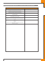
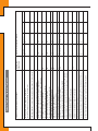
Kenmerkende producteigenschappen / technische gegevens staan in Bijlage 1, Tabel 2 achterin de handleiding.
Door bedrijfsinterne maatregelen is gewaarborgd dat seriematig geproduceerde haarden aan de essentiële eisen
van de van kracht zijnde EG-richtlijnen en de daarvan afgeleide normen voldoen.
Deze verklaring verliest haar geldigheid als zonder schriftelijke toestemming van DRU wijzigingen aan het toestel
worden aangebracht.
Namens DRU Verwarming B.V.
M.J.M Gelten
Algemeen directeur
NL
INSTAL L ATIEHANDL E I DI N G
3. VEILIGHEID
3.1 Algemeen
!LET OP •
Nederlands
•
Leest u dit hoofdstuk over veiligheid zorgvuldig door voordat u begint met installatie of onderhoud.
Houdt u zich aan de algemeen geldende voorschriften en de voorzorgsmaatregelen/veiligheidsinstructies in
deze handleiding.
3.2 Voorschriften
Installeer het toestel volgens de geldende Europese, nationale, lokale en bouwkundige (installatie)voorschriften.
Voor Nederland geldt onder meer het Bouwbesluit.
3.3 Voorzorgsmaatregelen / veiligheidsinstructies bij installatie
Ø
Ø
Ø
Ø
Ø
Ø
Ø
Ø
Ø
Ø
Ø
Ø
Ø
Ø
Ø
Ø
Ø
Ø
Ø
Ø
Ø
Ø
Ø
NL
Volg de onderstaande voorzorgsmaatregelen/veiligheidsvoorschriften nauwkeurig op:
Installeer en onderhoud de haard alleen als u een vakbekwame installateur op het gebied van houtgestookte
toestellen bent.
Plaats de haard alleen in een ruimte, waarbij de locatie, de bouwtechnische constructie en de activiteit in deze
ruimte geen gevaar opleveren door het branden van de haard.
Plaats de haard afhankelijk van het type ophanging op een vloer, tegen een wand of aan een plafond met
voldoende draagkracht.
Houd rekening met eventuele brandbare schouwbalken boven de haard. Verwijder deze of breng volgens de
bouwrichtlijnen voldoende niet-brandbaar isolatiemateriaal volgens Eurobrandklasse A1 EN 13501-1 aan.
Breng, indien u nog andere brandbare materialen aantreft, volgens de bouwrichtlijnen voldoende niet-brandbaar
isolatiemateriaal volgens Eurobrandklasse A1 EN 13501-1 aan.
Houd bij het plaatsen van een vrijstaande haard rekening met de minimaal vereiste ruimte van de haard tot een
niet-brandbare wand. Deze afstand bedraagt 50 mm.
Gebruik kachelpijpmateriaal, dat minimaal voldoet aan EN 1856-2 T600.
Houd bij het plaatsen van de haard en/of de kachelpijpen rekening met de minimale afstand tot brandbare
objecten en materialen (zie Bijlage 1, Tabel 2 èn het typeplaatje voorin deze installatiehandleiding).
Plaats, in geval van een brandbare vloer, een beschermende vloerplaat (zie hoofdstuk 5.4).
Dek een vrijstaande haard niet af en/of pak deze niet in met een isolatiedeken of enig ander materiaal.
Sluit de haard aan op een geschikt rookgaskanaal.
Verwijder de eventueel aanwezige afsluitklep of schuif in het rookgaskanaal van de bestaande openhaard.
Laat het rookgaskanaal vooraf inspecteren en reinigen door een erkend schoorsteenveegbedrijf.
Breng zelf geen wijzigingen aan de haard aan.
Gebruik uitsluitend originele onderdelen ter vervanging.
Zorg voor voldoende ventilatie in de opstellingsruimte, plaats zonodig een extra luchttoevoeropening.
Zorg ervoor dat er nooit onderdruk in de opstellingsruimte optreedt. Sluit, indien van toepassing, de
buitenluchtaansluiting aan en haal daarmee de verbrandingslucht direct van buiten de woning.
Extra informatie indien u een inzet-/ inbouwtoestel installeert:
Gebruik onbrandbaar en hittebestendig materiaal volgens Eurobrandklasse A1 EN 13501-1 voor de boezem
(inclusief de bovenkant van de boezem), het materiaal in de boezem en de achterwand waartegen het toestel
wordt geplaatst. Zowel plaatmateriaal als steenachtige materialen zijn hiervoor mogelijk.
Neem afdoende maatregelen volgens de bouwrichtlijnen om te hoge temperaturen (>85 °C) van een wand achter
de boezem te voorkomen, inclusief de materialen en/of voorwerpen die zich achter de wand bevinden.
Houd rekening met de minimaal vereiste inwendige afmetingen van de boezem.
Het is mogelijk om door middel van ventilatieroosters extra convectiewarmte uit de boezem te halen.
Sluit, indien van toepassing, de convectie-opening aan met een flexibele aluminium pijp en ventilatie-elementen.
Deze zijn als accessoire te bestellen bij uw leverancier.
Gebruik, indien van toepassing, hittebestendige elektrische aansluitingen en plaats deze vrij van het toestel.
INST AL L AT I E H AN DL E I D IN G
4. Uitpakken
Schenk aandacht aan de onderstaande punten bij het uitpakken:
Controleer het toestel met toebehoren op (transport)schade.
Installeer nóóit een beschadigde haard!
Neem, indien nodig, contact op met uw leverancier.
Nederlands
Ø
Ø
Ø
!LET OP Houd plastic zakken bij kinderen vandaan.
Ø
Ø
Ø
Ø
Ø
Ø
Ø
In Bijlage 1, Tabel 1, staat vermeld over welke onderdelen u na het uitpakken dient te beschikken.
Om transporttechnische redenen ligt de vlamkeerplaat bij sommige toestellen op de bodem van de haard.
Voor het plaatsen van deze vlamkeerplaat verwijzen we, indien van toepassing, naar hoofdstuk 9
'Toestelspecifieke informatie'.
Door het transport kunnen onderdelen verschoven zijn. Controleer de positie van de keerplaat en
binnenbekledingsplaten.
Controleer vóór plaatsing de werking van de luchtschuif, de deursluiting en het eventuele draaimechanisme.
Voor het monteren/demonteren van deze onderdelen verwijzen we, indien van toepassing, naar hoofdstuk 9
'Toestelspecifieke informatie'.
Verwijder het eventueel achtergebleven straalgrit uit de luchtschuif.
Neem, indien nodig, contact op met uw leverancier.
Voer de verpakking af via de reguliere weg.
NL
INSTAL L ATIEHANDL E I DI N G
5. Installatie
Lees de handleiding zorgvuldig door voor een goede en veilige installatie van het toestel.
Nederlands
5.1 Voorschriften
Ø
Ø
Ø
Installeer de haard volgens de geldende Europese, nationale, lokale en bouwkundige (installatie)voorschriften.
Houdt u zich aan de instructies zoals vermeld in deze handleiding.
DRU Verwarming geeft geen garantie op de installatie en het onderhoud van de haard en is niet verantwoordelijk
voor eventueel hierdoor ontstane gevolgschade.
5.2 Rookgaskanaal
Ø
Ø
Ø
Ø
Ø
Ø
Ø
Ø
Ø
Ø
Ø
Ø
Ø
Ø
Ø
Ø
Voor het rookgaskanaal gelden de volgende eisen:
Het rookgaskanaal moet van tevoren geïnspecteerd worden door een specialist.
Het rookgaskanaal dient geschikt te zijn voor het stoken van een houtgestookt toestel.
De haard dient te worden aangesloten op een enkel, ongedeeld rookgaskanaal.
Het rookgaskanaal dient schoon en lekdicht te zijn.
Gebruik voor het rookgaskanaal materiaal, dat minimaal voldoet aan EN 1856-1 T450.
Gebruik voor de kachelpijp materiaal, dat minimaal voldoet aan EN 1856-2 T600.
De versleping in het rookgaskanaal mag maximaal 1,5 meter bedragen met een minimale hoek van 45 graden
vanuit het horizontale vlak, mits de trek in het kanaal niet te laag is.
Bij achteraansluiting op de haard mag het horizontale deel van het rookgaskanaal maximaal 500 mm bedragen.
Bij gebruik van de achteraansluiting van de haard op een verticaal rookgaskanaal dient een T-stuk met roetzak te
worden toegepast.
De diameter van het rookgaskanaal moet minimaal gelijk zijn aan de diameter van de rookgasafvoer van de haard.
De trek van het rookgaskanaal moet minimaal 12 Pascal zijn.
Plaats eventueel een rookgasventilator indien er te weinig trek is of er onderdruk in de opstelruimte ontstaat door
mechanische ventilatie in de woning.
In een (te) sterk trekkend kanaal (30 - 40 Pa) dient zonodig een rookgasklep worden aangebracht. Hiermee kan de
trek worden geregeld. Uw toestel kan uitgevoerd zijn met een "remkap" om een eventuele hoge trek te remmen
(zie, indien van toepassing, hoofdstuk 9 'Toestelspecifieke informatie').
Maak bij het plaatsen van een flexibele pijp altijd gebruik van de dubbelwandige rvs-uitvoering met een “gladde”
binnenzijde.
Om roestvorming en beschadiging van de binnenbekleding van de haard door vocht te beperken, dient bovenop
het rookgaskanaal een regenkap geplaatst te worden.
Het rookgaskanaal dient zelfdragend te zijn en mag niet op de haard rusten.
5.3 Convectie
Bij het installeren van een toestel in een holle boezem moeten convectie-openingen worden gecreëerd. Open,
indien van toepassing, de eventueel aanwezige convectie-openingen op het toestel volgens de beschrijving in
hoofdstuk 9 ‘Toestelspecifieke informatie’. Indien er geen convectie-openingen op het toestel aanwezig zijn, dient
u de noodzakelijke boezembeluchting en -ontluchting zelf te realiseren. Ga hierbij uit van een minimale
boezemontluchting van 200 cm2 (aan de bovenzijde) en een minimale –beluchting van 200 cm2 (aan de
onderzijde). Plaats de ontluchting aan de bovenzijde minimaal 30 cm onder het plafond en minimaal 180 cm van
de vloer.
5.4 Toestellen met ventilator(en)
Toestellen, die zijn uitgevoerd met één of meerdere ventilatoren, verwarmen een ruimte sneller en verhogen het
comfort. Zodra de ventilator wordt ingeschakeld, is een aangenaam warme luchtstroom voelbaar. De ventilator is
op verschillende standen instelbaar. De luchtstroom kan zowel aan de voorzijde als via de convectie-openingen het
toestel verlaten. Voor meer informatie over toestellen met een ventilator, verwijzen we naar hoofdstuk 9
“Toestelspecifieke informatie”.
5.5 Landspecifieke installatie-eisen
Ø
NL
Installeer het toestel volgens de geldende Europese, nationale, lokale en bouwkundige (installatie)voorschriften.
Voor Nederland geldt onder meer het Bouwbesluit.
INST AL L AT I E H AN DL E I D IN G
5.6 Buitenluchtaansluiting (indien van toepassing)
Nederlands
Sommige haarden kunnen worden voorzien van een buitenluchtaansluiting. Voor een optimale werking van het
toestel dient in geval van een buitenluchtaansluiting met de volgende punten rekening te worden gehouden:
•
De doorlaat van de buitenluchtaansluiting en eventueel de doorlaat van een rooster mag niet kleiner zijn dan
doorlaat van de buitenluchtaansluiting op de haard.
•
Zorg ervoor dat er max. 4 pascal onderdruk ontstaat in de verbrandingsluchttoevoerleiding. Indien er een
hogere onderdruk ontstaat, zal de haard niet goed functioneren en kunnen er (hete) rookgassen terugstromen
in de toevoerleiding.
•
Vermijd het plaatsen van de buitenluchttoevoer in een onderdruk gebied aan de buitenkant van het huis.
Plaats, indien mogelijk, een toevoerleiding met T-stuk naar 2 zijdes van het huis.
•
De verbrandingsluchttoevoerleiding mag niet hoger als de onderkant van de haard geplaatst worden, dit om
het terugstromen van rookgassen te voorkomen.
•
De verbrandingsluchttoevoerleiding die op de haard wordt aangesloten wordt dient van onbrandbaar
materiaal te zijn.
•
De haard functioneert goed met een flexibele pijp van max. 11 mtr. en 4 bochten. Bij langere lengtes of meer
bochten is het raadzaam om een pijp met een grotere diameter (100-125mm) te plaatsen.
•
Indien een kruipruimte goed belucht wordt met open roosters mag hier de verbrandingslucht vandaan
gehaald worden. Indien er geen goede beluchting in de kruipruimte is dan kunnen hier schadelijke
radongassen aangezogen worden, dit is niet toegestaan volgens de nationale regels.
Nadere informatie over de buitenluchtaansluiting vindt u, indien van toepassing, in hoofdstuk 9 ‘Toestelspecifieke
informatie’.
5.7 Plaatsen haard algemeen
!Let op
•
•
•
•
!Tip
Ø
Ø
Ø
Ø
Ø
Ø
Ø
Breng zelf geen wijzigingen aan de haard aan.
Gebruik schone stoffen handschoenen, vermijd vingerafdrukken op de haard en kachelpijpen.
Plaats de haard afhankelijk van het type ophanging op een vloer, tegen een wand of aan een plafond met
voldoende draagkracht.
Plaats, in geval van een brandbare vloer, een brandwerende vloerplaat. De vloerplaat van niet-brandbaar
materiaal dient minimaal 300 mm voor de haard uit te steken en minimaal 300 mm breder te zijn dan de
haard.
Controleer deze afstanden, voor plaatsing, aan de hand van de geldende nationale/locale wetgeving.
Een vloerplaat beschermt tegen gloeiende asdeeltjes en voorkomt het vuil worden van bijvoorbeeld een marmeren
of plavuizen vloer. Daarom adviseren wij het gebruik van een brandwerende vloerplaat ook bij plaatsing van
toestellen aan de wand of aan het plafond.
Controleer op de maatschets van de haard welke diameter kachelpijp u nodig heeft (zie Bijlage 1, tabel 2).
Gebruik een kachelpijp, die minimaal voldoet aan de normen, zoals vastgelegd in EN 1856-2 T600.
Plaats de kachelpijpen zodanig, dat nooit een brandgevaarlijke situatie kan ontstaan.
Houd bij het plaatsen van een vrijstaande haard rekening met de minimaal vereiste ruimte van de haard tot een
niet-brandbare wand. Deze afstand bedraagt 50 mm.
Houdt bij het plaatsen van de haard en/of de kachelpijpen rekening met de minimale afstand tot brandbare
objecten en materialen zoals aangegeven in Bijlage 1, tabel 2;
Neem afdoende maatregelen om te hoge temperaturen van een eventuele wand achter de boezem te voorkomen.
Dit geldt ook voor materialen en/of voorwerpen die zich achter de wand bevinden.
Houdt u zich aan de eisen met betrekking tot het rookgaskanaal, zoals beschreven in paragraaf 5.2.
Voor eventuele toestelspecifieke aanwijzingen verwijzen we naar hoofdstuk 9 'Toestelspecifieke informatie'.
!LET OP Houd, indien u een inbouwtoestel installeert, rekening met:
•
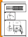
De minimale inbouwafmetingen volgens Bijlage 2, Afb. 1.
NL
INSTAL L ATIEHANDL E I DI N G
5.7.1 Vrijstaande / Designhaarden
5.7.1.1 Ombouwen bovenaansluiting naar achteraansluiting haard (indien van toepassing)
Nederlands
De haard wordt geleverd met een bovenaansluiting voor het aansluiten op het rookgaskanaal.
De bovenaansluiting kan, indien van toepassing, omgebouwd worden naar een achteraansluiting.
Ø
Ø
Ø
Ø
Ø
Ø
Ø
Ø
Ø
Ø
Volg hiervoor de onderstaande stappen (zie Bijlage 2, afb. 2):
Haal de vlamkeerplaat c.q. keerplaten uit de stookruimte (zie, indien van toepassing, hoofdstuk 9,
'Toestelspecifieke informatie').
Uw toestel kan uitgevoerd zijn met een extra stalen remkap (zie, indien van toepassing, hoofdstuk 9,
'Toestelspecifieke informatie'). Verwijder deze door de remkap naar voren te schuiven en uit de rails te halen.
Bij een achteraansluiting wordt deze remkap niet teruggeplaatst.
Verwijder de convectie-achterplaat van de haard door het losdraaien van de bouten.
Verwijder de doordrukplaat uit de convectie-achterplaat.
Verwijder de afdekplaat ten behoeve van de rookgasafvoer uit de achterwand van de haard door het losdraaien van
de 2 of 3 moeren.
Verwijder de rookgasafvoerring uit de bovenplaat door het losdraaien van de moeren en/of bouten.
Monteer de rookgasafvoerring op de achterwand met behulp van de bouten en/of moeren.
Zet de convectie-achterplaat weer vast met de bouten.
Monteer de afdekplaat ten behoeve van de rookgasafvoer in de opening in de bovenplaat met behulp van de
moeren.
Plaats de vlamkeerplaat c.q. keerplaten in omgekeerde volgorde weer terug.
5.7.1.2 Plaatsen vrijstaande haard, algemeen
Ø
Ø
Ø
Ø
Ø
Ø
Ø
Ø
Het plaatsen van de vrijstaande haard gebeurt als volgt:
Bepaal de plaats van de haard. De afmetingen van het toestel zijn weergegeven in Bijlage 2, afb 1.
Voor eventuele toestelspecifieke aanwijzingen verwijzen we naar hoofdstuk 9 'Toestelspecifieke informatie'.
Zorg ervoor dat er geen brandbare materialen aanwezig zijn.
Plaats, indien van toepassing, de vloerplaat.
Zet de haard op een deken of een stuk karton (in verband met een mogelijke beschadiging van de vloer) en daarna
op de gewenste plek.
Sluit de haard aan op het rookgaskanaal. Volg hierbij de aanwijzingen van de leverancier van het
rookgasafvoersysteem. Gebruik kachelpijpmateriaal, dat minimaal voldoet aan EN 1856-2 T600.
Verschuif de haard indien nodig en kantel deze iets zodat de deken of het karton weggehaald kan worden.
Voor de afronding van de installatie verwijzen we naar paragraaf 5.8.
5.7.1.3 Plaatsen Designhaard
Voor het plaatsen van een designhaard verwijzen we naar Hoofdstuk 9 'Toestelspecifieke informatie'.
NL
INST AL L AT I E H AN DL E I D IN G
5.7.2 Inzethaarden (bestaande en nieuwe situatie)
5.7.2.1 In bestaande schouw of boezem
Ø
Ø
Ø
Ø
Ø
Ø
Ø
Ø
Ø
Ø
Ø
Ø
Ø
Ø
Ø
Ø
Ø
Ø
Ø
Ø
Ø
Ø
!Let op
Ø
Ø
Ø
Ø
Ø
Ga voor het plaatsen van een inzethaard in een bestaande schouw of boezem als volgt te werk:
Bepaal de plaats van de haard. De afmetingen van het toestel zijn weergegeven in Bijlage 2, afb. 1.
Houd minimaal 10 mm ruimte tussen de haard en bouwkundige materialen.
Controleer de afmeting van de sparing. Indien noodzakelijk kunnen de wanden van de openhaard iets uitgebroken
worden. Zorg ervoor dat de rookkap voldoende ondersteund blijft.
Maak, indien van toepassing, ruimte voor de aansluiting van de convectie-openingen (zie, indien van toepassing,
hoofdstuk 9 'Toestelspecifieke informatie' en hoofdstuk 5.3 'Convectie') met een flexibele aluminium pijp en
ventilatie-elementen (zie hoofdstuk 5.4 'Toestellen met ventilator(en)'). Deze zijn als accessoire te bestellen bij uw
leverancier.
Let op met het stukadoren van de boezem. Stucprofielen maken de sparing kleiner.
Verwijder de eventueel bestaande klep van de openhaard of schuif en reinig de rookkap, zodat er geen roet
achterblijft.
Verwijder de haarddeur en demonteer het kader wanneer deze los is meegeleverd (zie hoofdstuk 9
'Toestelspecifieke informatie').
Verwijder de vermiculietplaten (markeer deze), de keerplaat en indien aanwezig de remkap voorzichtig uit de haard
(zie, indien van toepassing, hoofdstuk 9 'Toestelspecifieke informatie').
Leg de eventueel meegeleverde bodemplaat op de plek waar de haard geplaatst moet worden.
Draai de stelpoten in met de meegeleverde binnenzeskant schroevedraaier en controleer of ze goed verstelbaar
zijn. Er kan nog wat straalgrit aanwezig zijn.
Zorg ervoor dat er voor de toevoer van verbrandingslucht voldoende ruimte is onder de haard, wanneer er geen
sprake is van een buitenluchtaansluiting.
Indien van toepassing is een buitenluchtaansluiting mogelijk (zie, indien van toepassing, hoofdstuk 9
'Toestelspecifieke informatie').
Schuif de haard voorzichtig in het gat. Zorg dat er geen beschadigingen ontstaan.
Sluit, indien van toepassing, de convectie-opening (zie hoofdstuk 5.3 'Convectie') aan met de flexibele aluminium
pijp en ventilatie-elementen (zie hoofdstuk 5.4 'Toestellen met ventilator(en)');
De haard mag de rookgasafvoer nooit dragen.
Maak een goede, luchtdichte afdichting tussen de haard en de rookgasafvoer, eventueel met een registerplaat en
bij voorkeur met een vaste kachelpijp of rvs dubbelwandige flexibele pijp, die minimaal voldoet aan de norm EN
1856-2 T600.
Indien toepasbaar en afhankelijk van de nationale regelgeving mag de verbinding tussen het bestaande
rookgaskanaal en de haard met hittebestendige keramische wol worden afgestopt.
Ga als volgt te werk:
Controleer of de openhaard-klep is verwijderd.
Verwijder het kader (indien het kader al geplaatst is).
Verwijder de bodemplaten en draai de haard met de stelpoten zo ver mogelijk naar beneden, om ruimte te creëren
voor de ceramische wol.
Vul de eventuele ruimte achter de haard op met vuurvast isolatiemateriaal, zodat hierachter geen vuil kan komen.
Verwijder de vlamkeerplaat.
Breng de keramische wol tussen de bovenzijde van de haard en de schoorsteen aan voor een luchtdichte
aansluiting.
Draai de haard met de stelpoten weer omhoog en controleer of de keramische wol goed afdicht.
Leg de vlamkeerplaat hierna weer op de plaats terug (zie hoofdstuk 9 'Toestelspecifieke informatie').
Controleer telkens na het schoorsteenvegen of de aansluiting nog luchtdicht is.
Voor het rechtstreeks aansluiten van een rvs flexibele pijp op de haard is een handige kit leverbaar via uw
leverancier. Het gebruik van een kit is echter niet voor alle toestellen noodzakelijk (zie, indien van toepassing,
hoofstuk 9 'Toestelspecifieke informatie').
Draai, nadat de haard is aangesloten, de stelpoten met de bijbehorende inbussleutel zodanig uit, dat de haard in de
gewenste positie staat. Zorg ervoor dat hierbij de verbrandingsluchttoevoer niet geblokkeerd wordt.
Plaats de remkap voor de uitgang, de binnenbekledingsplaten in omgekeerde volgorde weer terug en leg de
keerplaat tegen de achterwand en op de profielen (zie, indien van toepassing, hoofdstuk 9 'Toestelspecifieke
informatie').
Controleer met een zaklamp of een dunne schroevendraaier of de gaten van de secundaire beluchting in de
achterwand recht voor de sparingen in de binnenbekleding zitten.
Plaats, indien van toepassing, het kader om de haard (zie, indien van toepassing, hoofdstuk 9 'Toestelspecifieke
informatie').
Nederlands
Ø
Ø
Ø
NL
INSTAL L ATIEHANDL E I DI N G
5.7.2.2 Bij een nieuwe situatie
Nederlands
Ø
Ø
Ø
Ø
Ø
Ø
Ø
Ø
Ø
Ø
Ø
Ø
Ø
Ø
Ø
Ø
Ø
Ø
Ø
Ø
Ø
Ø
Ø
NL
Ga voor het plaatsen van een inzethaard in een nieuw te bouwen boezem als volgt te werk:
Bepaal de plaats van de haard. De afmetingen zijn weergegeven in Bijlage 2, afb. 1.
Plaats de haard op een vloer met voldoende draagkracht.
Maak, indien van toepassing, een sparing voor een buitenluchtaansluiting (zie, indien van toepassing, hoofdstuk 9
'Toestelspecifieke informatie').
Gebruik onbrandbaar en hittebestendig materiaal volgens Eurobrandklasse A1 EN 13501-1 voor de plaat op de
vloer, de boezem (inclusief de bovenkant van de boezem), het materiaal in de boezem en de achterwand
waartegen het toestel wordt geplaatst. Zowel plaatmateriaal als steenachtige materialen zijn hiervoor mogelijk.
Houd minimaal 10 mm ruimte tussen de haard en bouwkundige materialen.
Let op met het stukadoren van de boezem. Stucprofielen maken de sparing kleiner.
Houd rekening met het uitzetten van de haard. Houd de haard vrij van stucwerk.
Breng, indien er sprake is van een brandbaar plafond, 30 cm onder het plafond in de boezem een brandwerende
plaat met daarop een 10 cm dikke warmte-isolerende laag aan.
Indien er brandbare materialen (bv. houten vloerdelen/balken etc) onder of achter de haard aanwezig zijn, dient
voldoende onbrandbaar isolatiemateriaal volgens Eurobrandklasse A1 EN 13501-1 te worden aangebracht.
Houd hierbij de nationale regelgeving in acht.
Plaats in geval van een brandbare muur een 10 cm dikke brandveilige muur.
Bouw het plateau of de verhoging van hittebestendig materiaal.
Leg de meegeleverde stalen plaat op de plek voor de haard. Maak hierin, indien van toepassing, een sparing voor
de buitenluchtaansluiting. Verwijder de haarddeur en demonteer het kader wanneer deze los is meegeleverd.
Verwijder de haarddeur en demonteer het kader wanneer deze los is meegeleverd (zie hoofdstuk 9
'Toestelspecifieke informatie').
Plaats de haard.
Sluit, indien van toepassing, de buitenluchtaansluiting aan (zie hoofdstuk 9 'Toestelspecifieke informatie').
Sluit, indien van toepassing, de convectie-opening (zie hoofdstuk 5.3 'Convectie') aan met de flexibele aluminium
pijp en ventilatie-elementen (zie hoofdstuk 5.4 'Toestellen met ventilator(en)'). Houdt deze elementen op minimaal
30 cm afstand van het plafond.
Gebruik enkelwandige rvs kachelpijpen of rvs dubbelwandige flexibele pijpen, die minimaal voldoet aan de norm
EN 1856-2 T600.
De haard mag de rookgasafvoer nooit dragen.
Draai, nadat de haard is aangesloten, de stelpoten met de bijbehorende inbussleutel zodanig uit, dat de haard in de
gewenste positie staat. Zorg ervoor, dat de verbrandingsluchttoevoer hierbij niet geblokkeerd wordt.
Plaats de remkap voor de uitgang, de binnenbekledingplaten in omgekeerde volgorde weer terug en leg de
keerplaat tegen de achterwand en op de profielen (zie hoofdstuk 9 'Toestelspecifieke informatie').
Controleer met een zaklamp of een dunne schroevendraaier of de gaten van de secundaire beluchting in de
achterwand recht voor de sparingen in de binnenbekleding zitten.
Plaats de deur weer terug en indien van toepassing het kader om de haard (zie, indien van toepassing, hoofdstuk 9
'Toestelspecifieke informatie').
Plaats, in geval van een brandbare vloer, een brandwerende vloerplaat voor de haard. De vloerplaat van
niet-brandbaar materiaal dient minimaal 300 mm voor de haard uit te steken en minimaal 300 mm breder te zijn
dan de haard.
INST AL L AT I E H AN DL E I D IN G
Ø
Ø
Ø
Ø
Ø
Ø
Ø
Ø
Ø
Ø
Ø
Ø
Ø
Ø
Ø
Ø
Plaatsen met inmetselcassette (indien van toepassing):
Plaats de haard met inmetselcassette op een vloer met voldoende draagkracht.
Plaats de inmetselcassette voor een brandveilige muur.
Plaats, in geval van een brandbare muur, een 10 cm dikke brandveilige muur.
Plaats de inmetselcassette waterpas op de gewenste hoogte en zet deze vast met metalen ankers.
Zet bij een hoekmodel de trekstang vast aan de muur en stel deze.
Sluit het rookgaskanaal aan op de ring van de cassette.
De cassette is niet geschikt om een rookgaskanaal te dragen; deze moet zelfdragend zijn.
Gebruik onbrandbaar en hittebestendig materiaal volgens Eurobrandklasse A1 EN 13501-1 voor de boezem
(inclusief de bovenkant van de boezem), het materiaal in de boezem en de achterwand waartegen het toestel
wordt geplaatst. Zowel plaatmateriaal als steenachtige materialen zijn hiervoor mogelijk.
Indien de boezem van hittebestendige platen volgens Eurobrandklasse A1 EN 13501-1, zoals promafour,
promatect, nobranda e.d., gemaakt wordt, kunnen deze aan de cassette vastgezet worden.
Steenachtige materialen mogen niet op de cassette rusten; gebruik hiervoor een baksteenlatei met keramisch vilt.
Laat 6 mm ruimte tussen de cassette en de boezemwanden.
Bekleed de cassette met 6 cm hittebestendig isolatiemateriaal.
Houd rekening met het uitzetten van de cassette. Houd de cassette vrij van stucwerk.
De boezem mag aan de buitenzijde niet warmer worden dan 90 graden Celsius.
Breng, indien er sprake is van een brandbaar plafond, 30 cm onder het plafond in de boezem een brandwerende
plaat met daarop een 10 cm dikke warmte-isolerende laag aan.
Zet de haard voor de inmetselcassette.
Draai de stelpoten in en controleer of ze goed verstelbaar zijn. Er kan nog wat straalgrit aanwezig zijn.
Schuif de haard voorzichtig in het gat. Zorg dat er geen beschadigingen ontstaan.
Draai de stelpoten met de bijbehorende inbussleutel zodanig, dat de haard in de gewenste positie staat. Zorg dat
er onder de haard voldoende ruimte overblijft voor de toevoer van verbrandingslucht.
Maak een goede, luchtdichte afdichting tussen de haard en de rookgasafvoer.
Houd minimaal 10 mm ruimte tussen de haard en de cassette.
Plaats, indien van toepassing, de remkap voor de uitgang, de vermiculietplaten in omgekeerde volgorde weer
terug en leg de keerplaat tegen de achterwand en op de profielen.
Plaats het kader indien deze los is meegeleverd.
Plaats, in geval van een brandbare vloer, een brandwerende vloerplaat voor de haard. De vloerplaat van
niet-brandbaar materiaal dient minimaal 300 mm voor de haard uit te steken en minimaal 300 mm breder te zijn
dan de haard.
Nederlands
Ø
Ø
Ø
Ø
Ø
Ø
Ø
Ø
NL
5.7.3 Inbouwhaarden
Ø
Ø
Ø
Ø
Ø
Ø
Ø
Ø
Ø
Ø
Ø
Ø
Ø
Ø
Bepaal de plaats van de kachel.
Schuif het inbouwframe (1) in de gewenste positie.
Gebruik onbrandbaar en hittebestendig materiaal volgens Eurobrandklasse A1 EN 13501-1 voor de plaat op de
vloer, de boezem (inclusief de bovenkant van de boezem), het materiaal ín de boezem en de achterwand
waartegen het toestel wordt geplaatst. Zowel plaatmateriaal als steenachtige materialen zijn hiervoor mogelijk.
Breng, indien er sprake is van een brandbaar plafond, 30 cm onder het plafond in de boezem een brandwerende
plaat met daarop een 10 cm dikke warmte isolerende laag aan.
Plaats de haard waterpas op de gewenste hoogte en zet deze vast met metalen ankers.
Sluit het rookgaskanaal aan op de ring van de haard.
Sluit eventuele convectie-openingen (zie hoofdstuk 5.3 'Convectie') altijd aan met hittebestendige flexibele buis en
en ventilatie-elementen (zie hoofdstuk 5.4 'Toestellen met ventilator(en)') om het stucwerk te beschermen tegen
hoge temperaturen. Wanneer de boezem van onbrandbare materialen (bv. schoon metselwerk) is gemaakt, is dit
niet noodzakelijk.
Zorg dat er onder de haard voldoende ruimte is voor de toevoer van verbrandingslucht. Wanneer de ring van de
buitenluchtaansluiting niet wordt gebruikt, moet deze minimaal 20 mm vrij blijven voor voldoende
verbrandingslucht.
Sluit, indien van toepassing, de buitenluchtaansluiting aan (zie hoofdstuk 9 'Toestelspecifieke informatie').
De haard is niet geschikt om een rookgaskanaal te dragen, deze moet zelfdragend zijn.
Steenachtige materialen mogen beslist niet op de haard rusten. Gebruik hiervoor bv. een baksteenlatei met
keramisch vilt.
Zorg dat de opening in de boezem 6 mm ruimer is dan het inbouwframe.
De boezem mag aan de buitenzijde niet warmer worden dan 90 graden Celsius;
Plaats, in geval van een brandbare vloer, een brandwerende vloerplaat voor de haard. De vloerplaat van
niet-brandbaar materiaal dient minimaal 300 mm voor de haard uit te steken en een minimaal 300 mm breder te
zijn dan de haard.
5.8 Afronden installatie
Ø
Ø
Ø
Ø
Ø
Controleer of er geen gruis, stof of andere materialen in de boezem achterblijven (i.v.m. stank).
Gebruik schone stoffen handschoenen en vermijd vingerafdrukken op de haard en kachelpijpen.
Controleer of de binnenbekleding en de keerplaten goed geplaatst zijn in de haard (zie, indien van toepassing,
hoofdstuk 9 'Toestelspecifieke informatie'). Verbeter zonodig de positie van deze platen.
Controleer of de gaten van de secundaire beluchting in de achterplaat recht voor de sparingen in de
binnenbekleding zitten.
Reinig de haard met een zachte doek en controleer deze op beschadigingen. Spuit de haard eventueel bij met de
meegeleverde spuitbus. Lees hiervoor de gebruiksaanwijzing op het etiket. Controleer altijd eerst de kleur op een
stuk wit papier of karton voordat u de haard bijwerkt.
Lees eerst de gebruikershandleiding aandachtig door, voordat de haard in gebruik wordt genomen.
Voor het aansteken en stoken van de haard verwijzen wij naar de gebruikershandleiding.
INSTAL L ATIEHANDL E I DI N G
6. Oplevering
Ø
U dient de gebruiker vertrouwd te maken met de haard. U dient haar/hem onder meer te instrueren over de
Nederlands
Ø
ingebruikname, het stoken en het onderhoud van de haard.
Wijs er bij ingebruikname op, dat
•
na een verbouwing of bij nieuwbouw alle bouwmaterialen goed moeten opdrogen i.v.m. het aanhangen van
stof (o.a. rookdeeltjes) aan vochtige oppervlakten;
•
bij de eerste keer stoken vluchtige componenten uitdampen uit lak, materialen e.d.;
•
de ruimte goed wordt geventileerd.
Ø
Ø
Wijs op de noodzaak om het rookgaskanaal minstens één keer per jaar door een specialist te laten inspecteren en
reinigen.
Overhandig de gebruiker de gebruikershandleiding én de installatiehandleiding (de installatiehandleiding dient bij
het toestel bewaard te blijven).
7. Onderhoud
In de Gebruikershandleiding wordt een aantal tips/instructies gegeven voor het onderhoud van de haard. Tevens is
vermeld hoe een aantal onderdelen vervangen kan worden.
8. Storingen
In de Gebruikershandleiding staat een tabel met een overzicht van storingen die kunnen optreden, de mogelijke
oorzaak en de oplossing.
NL
INST AL L AT I E H AN DL E I D IN G
9 Toestelspecifieke informatie
•
De toestelspecifieke instructies, zoals beschreven in dit hoofdstuk, gaan boven de instructies in de overige
hoofdstukken! Houd bij twijfel de instructies in hoofdstuk 9 aan of neem contact op met uw leverancier.
De toestelspecifieke informatie, zoals beschreven in de paragrafen 9.1 tot en met 9.4 geldt voor alle, in deze
handleiding beschreven, modellen. Aanvullende installatie-instructies (per toestel) worden beschreven in
paragraaf 9.5.
Nederlands
!LET OP •
9.1 Luchtschuif en rookgasafvoer
9.1.1 Luchtschuif
Controleer bij installatie en onderhoud van het toestel de werking van de luchtschuif (zie Bijlage 2, afb. 4).
De mogelijkheid bestaat, dat tijdens transport staalgrit in de luchtschuif is gekomen. Indien de luchtschuif niet
soepel loopt, moet deze worden gereinigd. Hiertoe dient de luchtschuif te worden gedemonteerd. De luchtschuif is
verend opgehangen door middel van een bout en een veer, die zich onder de afdekplaat bevinden.
Let op!
Ø
Ø
Ø
Let op!
Ø
Ga bij het demonteren van de luchtschuif als volgt te werk (zie Bijlage 2, afb. 4):
Indien een buitenluchtaansluiting is gemonteerd, dient deze eerst verwijderd te worden, voordat de luchtschuif
gedemonteerd kan worden (voor het verwijderen van de buitenluchtaansluiting: zie hoofdstuk 9.5).
Verwijder de vermiculietplaten van de bodem (zie hoofdstuk 9.2.1).
Verwijder daarna het vierkante plaatje, dat in een uitsparing onder de vermiculiet bodemplaten ligt.
Draai de inbusbout los met de inbussleutel.
Zodra de bout is losgedraaid, valt de luchtschuif naar beneden. Vang de luchtschuif op!
Controleer de luchtschuif en reinig deze zonodig.
Voor het terugplaatsen van de luchtschuif dienen de acties zoals beschreven bij het demonteren in omgekeerde
volgorde te worden uitgevoerd.
9.1.2 Rookgasafvoer
Ø
Ø
Ø
Ø
De rookgasafvoer heeft een aansluiting met een diameter van 150 mm (6"). De aansluiting kan worden gerealiseerd
met een vaste pijp van 150 mm (6"). De rookgasafvoer kan aan de boven- of achterzijde van het toestel worden
aangesloten (zie Bijlage 2, afb. 2).
Ga bij een aansluiting via de achterzijde als volgt te werk:
Schroef de 2 bouten los van de afvoerring die aan de bovenzijde van het toestel is gemonteerd.
Schroef de bouten in de plaat aan de achterzijde van het toestel los.
Monteer deze plaat aan de bovenzijde van het toestel op de plek waar de afvoerring heeft gezeten.
Monteer de afvoerring aan de achterzijde van het toestel door de 2 bouten vast te schroeven.
9.1.3 Hitteschild (optioneel)
Door gebruik te maken van een hitteschild kan het toestel dichter tegen de wand geplaatst worden. Deze
'hitteschild-kit' bestaat uit twee afschermplaten en is optioneel verkrijgbaar via uw leverancier.
Let op!
Een hitteschild kan alleen worden geplaatst indien de rookgasafvoer aan de bovenzijde van het toestel is
aangesloten.
Ø
Ø
Ø
Ga als volgt te werk:
Afschermplaat die aan het toestel bevestigd wordt:
Draai de 4 voorgemonteerde boutjes aan de achterzijde van het toestel een paar slagen los (zie Bijlage 2, afb. 5).
Plaats de plaat tegen de achterzijde van het toestel.
Schroef de 4 boutjes vast.
Ø
Ø
Ø
Afschermplaat die tegen de afvoerpijp bevestigd wordt:
(alleen van toepassing bij een enkelwandige pijp)
Laat de afschermplaat aan de achterzijde van het rookgaskanaal op het toestel rusten.
Druk de plaat vervolgens tegen het rookgaskanaal.
Boor 4 gaatjes (Ø 4 mm) en schroef de plaat vast met de bijgeleverde schroeven (zie Bijlage 2, afb. 6).
NL
INSTAL L ATIEHANDL E I DI N G
9.2 Binnenbekleding
9.2.1 Vermiculiet
Nederlands
De vermiculietplaten bij de haard bevinden zich op de bodem en tegen de achterwand en zijwanden van het
toestel.
In de volgende situaties dienen de vermiculietplaten te worden uitgenomen:
•
Bij het demonteren van de luchtschuif (zie hoofdstuk 9.1.1).
•
Bij vervanging van de vermiculietplaten.
De bodemplaten worden hierbij als eerste uitgenomen en de achterplaten als laatste.
Het inleggen van de vermiculietplaten geschiedt in omgekeerde volgorde.
!Let op
Zorg ervoor dat de vermiculietplaten weer in de oorspronkelijke positie worden teruggeplaatst! Zo dient de
achterplaat met de kleine, niet verzonken, gaten zichtbaar naar voren te worden geplaatst.
9.2.2 Vlamkeerplaat
Bij levering ligt de vlamkeerplaat (zie Bijlage 2, afb. 7) bovenin het toestel.
Bij onderhoud aan het toestel dient de vlamkeerplaat te worden uitgenomen.
Ø
Ø
Ø
!Let op
NL
Ga hierbij als volgt te werk:
Pak de vlamkeerplaat vast en duw de rechterzijde omhoog.
Schuif de vlamkeerplaat over de richel naar rechts.
Laat de linkerzijde van de vlamkeerplaat zakken en neem de vlamkeerplaat uit.
Het plaatsen van de vlamkeerplaat geschiedt in omgekeerde volgorde.
Het rvs-profiel dient aan de voorzijde geplaatst te worden met de schroefkoppen aan de bovenzijde
(zie Bijlage 2, afb. 7).
INST AL L AT I E H AN DL E I D IN G
9.3 Deur
Ø
Nederlands
Ø
Controleer bij installatie of onderhoud het sluiten van de deur.
Ga hierbij als volgt te werk:
Controleer de afdichting van de deur door een vel papier tussen de deur en de haard te plaatsen. Na het sluiten van
de deur mag het vel papier er niet makkelijk uitgetrokken kunnen worden. Controleer de haard rondom.
Indien er geen sprake is van een goede afdichting van de deur(en):
Vervang de deurafdichting (zie paragraaf 9.3.1)
9.3.1 Vervangen deurafdichting
Ø
Ø
Ø
Ø
Ga voor het vervangen van de deurafdichting als volgt te werk:
Verwijder de deurafdichting door deze uit het geïntegreerde gootje te halen.
Verwijder overtollige kitresten uit het gootje van de deurafdichting.
Breng met hittebestendig kit een nieuwe laag kit aan in het gootje.
Plaats de nieuwe deurafdichting.
NL
9.4 Ruit
9.4.1 (De)monteren ruit in deur
!Let op
!Tip
Ø
Ø
Ø
Ø
Ø
Ø
!Let op
•
Voorkom beschadiging bij het verwijderen/plaatsen van de ruit.
•
Vermijd/verwijder vingerafdrukken op de ruit(en) omdat deze inbranden.
Gebruik bij vingerafdrukken op de ruit(en) de meegeleverde ruitenreiniger.
Voor het verwijderen en daarna weer monteren van de ruit in de deur volgt u onderstaande aanwijzingen
(zie Bijlage 2, afb. 8).
Demonteren ruit in deur:
Open de deur.
Til de deur eruit door deze naar boven te schuiven.
Leg de deur op een vlakke ondergrond.
Draai de 4 boutjes, die de klemmetjes vasthouden, los.
Til de ruit eruit. Hierbij wordt ook de ruitafdichting uitgenomen.
Monteren ruit in deur:
Monteer de ruit en plaats de deur weer terug door de stappen genoemd bij het demonteren van de ruit in
omgekeerde volgorde uit te voeren.
•
•
Draai de bouten niet te vast ter voorkoming van afbreken en/of doldraaien: vast=vast.
Plaats de ruit (inclusief nieuwe ruitafdichting) met het logo rechtsonder.
9.5 Aanvullende installatie-instructies per toestel
9.5.1 Ivar 8 LowEA
9.5.1.1 Buitenluchtaansluiting
Voor deze toestellen is als accessoire een buitenluchtaansluiting verkrijgbaar. Montage geschiedt altijd aan de
onderzijde van het toestel. Afvoer is bij deze toestellen alleen via de achterzijde mogelijk.
Ø
Ø
Ø
Ø
Ø
Let op!
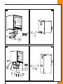
Ga bij het aansluiten van de buitenluchtaansluiting als volgt te werk (zie Bijlage 2, afb. 9a + 9b):
Draai de 5, op de buitenluchtaansluiting, voorgemonteerde bouten los.
Plaats de buitenluchtaansluiting tegen de plaat, die zich aan de onderzijde van het toestel bevindt.
Schroef de 5 bouten weer vast.
Schroef de bak ten behoeve van de achteraansluiting met 4 bouten vast.
Sluit de flexibele slang aan op de ronde ‘pijpmond’ van bovengenoemde bak.
De flexibele slang kan alleen van de achterzijde worden aangevoerd.
De ronde pijpmond ten behoeve van de onderaansluiting is niet nodig bij de installatie en dient verantwoord te
worden afgevoerd.
INSTAL L ATIEHANDL E I DI N G
9.5.2 Ivar 8 StoreEA
9.5.2.1 Buitenluchtaansluiting
Nederlands
Voor deze toestellen is als accessoire een buitenluchtaansluiting verkrijgbaar. Montage geschiedt altijd aan de
onderzijde van het toestel. Afvoer is bij deze toestellen alleen via de achterzijde mogelijk.
Ga bij het aansluiten van de buitenluchtaansluiting als volgt te werk (zie Bijlage 2, afb. 10a + 10b):
Draai de 4 schroeven van de reflectieplaat uit en verwijder de plaat. De reflectieplaat bevindt zich onder de
luchtschuif en beschermt het onder de kachel gestapelde hout tegen de hoge temperaturen, die in het toestel
ontstaan.
Ø
Breek het plaatje aan de achterzijde van het toestel met een hamer uit.
Ø
Draai de 5, op de buitenluchtaansluiting, voorgemonteerde bouten los.
Ø
Plaats de buitenluchtaansluiting tegen de plaat, die zich aan de onderzijde van het toestel bevindt.
Ø
Schroef de 5 bouten weer vast.
Ø
Schroef de bak ten behoeve van de achteraansluiting met 4 bouten vast.
Ø
Sluit de flexibele slang aan op de ronde ‘pijpmond’ van bovengenoemde bak.
De flexibele slang kan alleen van de achterzijde worden aangevoerd.
Let op! De ronde pijpmond ten behoeve van de onderaansluiting is niet nodig bij de installatie en dient verantwoord te
worden afgevoerd.
LET OP! De reflectieplaat moet altijd worden teruggeplaatst!
Ø
NL
INST AL L AT I ON M AN U A L
Contents
English
1. Introduction
2. EC Declaration of Conformity
3. SAFETY
3.1 General
3.2 Regulations
3.3 Precautions/safety instructions during installation
4. Unpacking
5. Installation
5.1 Regulations
5.2 Flue duct
5.3 Country-specific installation requirements
5.3.1 HETAS amendments
5.3.2 The Clean Air Act 1993 and Smoke Control Areas
5.4 Installing the fire
5.4.1 Free-standing/design fires
5.4.2 Insert fires (existing and new situation)
5.4.3 Built-in fires
5.5 Completing installation
6. Delivery
7. Maintenance
8. Malfunctions
9. Appliance-specific information
9.1 Smoke control area United Kingdom
9.2 Air slide valve and flue gas exhaust
9.2.1 Air slide valve
9.2.2 Flue gas exhaust
9.2.3 Heat shield (optional)
9.3 Interior lining
9.3.1 Vermiculite
9.3.2 Flame baffle plate
9.4 Door
9.4.1 Replacing door seal
9.5 Glass pane
9.5.1 (Dis)assembly of the glass pane
9.6 Supplementary installation instructions per appliance
9.6.1 Ivar 8 LowEA
9.6.1.1 Outside air connection
9.6.2 Ivar 8 StoreEA
9.6.2.1 Outside air connection
Annex 1: Parts included with delivery
Annex 2: Technical information
UK
INSTAL L ATIO N MA N U A L
1. Introduction
English
As a manufacturer of fires, DRU Verwarming develops and produces products according to the highest possible
English quality, performance and safety requirements. These woodburning Dik Geurts fires are provided with a CE
mark that is only awarded for fires complying with the essential requirements of the European Construction
Products Regulation, including requirements made of safety, the environment and energy consumption.
An installation manual and user manual is supplied with the fire. An installer must be certified and a competent
professional in the field of woodburning appliances.
The installation manual provides the information you need to install the fire in such a way that it works properly
and safely.
This manual covers installation of the fire and the applicable instructions. You will also find the technical details of
the fire.
The figures are annexed at the back of this booklet.
You must fully and carefully read the installation manual before using it to install the fire. If you have any
questions or doubts always contact your supplier.
The user manual gives you the information you need to ensure that the appliance works properly and safely.
Carefully read the user manual before starting to use the fire.
The manuals include the following indications to show important information:
Action to take
Tip!
Suggestions and advice
!Caution These instructions are required to prevent possible problems during installation and/or use.
!CAUTION These instructions are required to prevent fire, personal injury or other serious damage.
Ø
After delivery you must give the user manual and this installation manual to the user.
The user must safely keep the user manual and installation manual.
UK
INST AL L AT I ON M AN U A L
2. EC DECLARATION OF
English
The undersigned, representative of:
Manufacturer:
DRU Verwarming BV
Postbus 1021
NL-6920 BA Duiven
Ratio 8, NL-6921 RW Duiven
hereby declares that the design and construction of the woodburning heating appliance supplied by DRU satisfies
the essential requirements of the Construction Products Regulation and is produced and distributed according to
the requirements of the Belgian Royal Decree of 12 October 2010 for the regulation of the minimum requirements
of efficiency and emission levels of pollutants for solid fuel heating equipment.
The product properties/technical information is included in annex 1, Table 2 at the back of the manual. Internal
Product:
Type:
EEC directives:
Applied harmonised standards:
Notified body:
Wood fired heating appliance
Ivar 8 LowEA
89/106/EEC
NEN-EN-13240, NEN-EN-13240/A2
S.G.S. Nederland B.V. Reg.nr. 0608
Product:
Type:
EEC directives:
Applied harmonised standards:
Notified body:
Wood fired heating appliance
Ivar 8 StoreEA
89/106/EEC
NEN-EN-13240, NEN-EN-13240/A2
S.G.S. Nederland B.V. Reg.nr. 0608
company measures guarantee that the serial production fires satisfy the essential requirements of the applicable
EC directives and their derivative standards.
This declaration is no longer valid if changes are made to the appliance without written permission from DRU.
On behalf of DRU Verwarming B.V.
M. J. M Gelten
Managing director
UK
INSTAL L ATIO N MA N U A L
3. SAFETY
3.1 General
!CAUTION •
English
•
Carefully read this section about safety before you start installation or maintenance.
Comply with the generally applicable conditions and the precautionary measures/safety instructions in this
manual.
3.2 Regulations
Install the appliance according to the applicable European, national, local and construction (installation)
regulations.
In the Netherlands this includes the Building Decree.
3.3 Precautions/safety instructions during installation
Ø
Ø
Ø
Ø
Ø
Ø
Ø
Ø
Ø
Ø
Ø
Ø
Ø
Ø
Ø
Ø
Ø
Ø
Ø
Ø
Ø
Ø
Ø
Ø
UK
Carefully comply with the precautionary measures/safety regulations below:
Only install and maintain the fire if you are a trained installer of woodburning appliances.
Only install the fire in a space where the location, the technical construction and the activity in this space cannot
involve any danger due to the burning of the fire.
Depending on the type of suspension, install the fire on a floor, against a wall or on a ceiling with sufficient load
bearing capacity.
Take account of any flammable chimney beams above the fire. Remove them or apply sufficient non-flammable
insulation material according to the construction regulations under European fire classification A1 EN 13501-1.
If you find other flammable materials, apply sufficient non-flammable insulation material according to the
construction regulations under European fire classification A1 EN 13501-1.
When installing a free-standing fire take account of the minimum required distance from the fire to a
non-flammable wall. This distance amounts to 50 mm.
Use heater piping material that at least suffices with regard to EN 1856-2 T600.
When installing the fire and/or the flue pipes respect the minimum distance to flammable objects and materials
(see Annex 1, Table 2 and the data plate at the front of this installation manual).
Lay a protective floor plate if the floor is flammable (see section 5.4).
Never cover a free-standing fire and/or pack it with an insulation blanket or any other material.
Connect the fire to a suitable flue duct.
Remove any stop valve or slide in the flue duct of the existing open hearth.
Have the flue duct inspected and cleaned by a certified chimney sweeping company beforehand.
Do not make any changes to the fire yourself.
Only use original parts for replacement.
Ensure sufficient ventilation in the installation space. Fit an extra air supply opening if necessary.
Make sure that there is never underpressure in the installation space. If applicable, connect the outside air
connection to immediately extract the combustion air to outside the home.
Extra information if you are installing an insert/built-in appliance:
Use non-combustible and heat-resistant material according to European fire classification A1 EN 13501-1 for the
chimney breast (including the upper face), the material in the chimney breast and the back wall against which the
appliance is fitted. Plate material or stony materials can be used for this.
Take adequate measures according to the construction regulations to prevent too high temperatures (>85 °C) of a
wall behind the chimney breast, including the materials and/or objects behind the wall.
Take account of the minimum required internal dimensions of the chimney breast.
Convection heat can be extracted from the chimney breast by using ventilation grates.
If applicable connect the convection opening with a flexible aluminium pipe and ventilation elements.
These accessories can be ordered from your supplier.
If applicable use heat-resistant electrical connections and fit them away from the appliance.
INST AL L AT I ON M AN U A L
4. Unpacking
Follow the below points below when unpacking:
Check the appliance with accessories for (transport) damage.
Never install a damaged fire!
If necessary contact your supplier.
English
Ø
Ø
Ø
!CAUTION Keep plastic bags away from children.
Ø
Ø
Ø
Ø
Ø
Ø
Annex 1, Table 1 mentions which parts you must have after unpacking.
For technical transport reasons the flame baffle plate is at the bottom of the fire with some appliances.
For fitting this flame baffle plate we refer to section 9 'Appliance-specific information' as applicable.
Transport may have caused parts to move around. Check the position of the baffle plate and inner lining plates.
Before installing check the operation of the air slide valve, door locking and any turning mechanism.
For the assembly/disassembly of these parts we refer to section 9 'Appliance-specific information' as applicable.
Remove any remaining blasting grit from the air slide valve.
If necessary contact your supplier.
Dispose of packaging in accordance with local regulations.
5. Installation
Read the manual carefully to ensure the correct and safe installation of the appliance.
5.1 Regulations
Ø
Ø
Ø
Install the fire according to the applicable European, national, local and construction (installation) regulations.
Follow the instructions as given in this manual.
DRU Verwarming provides no guarantee to cover installation and maintenance of the fire and is not responsible
for any resulting consequential damage.
5.2 Flue duct
Ø
Ø
Ø
Ø
Ø
Ø
Ø
Ø
Ø
Ø
Ø
Ø
Ø
Ø
Ø
Ø
The following requirements apply for the flue duct:
The flue duct must be inspected by a specialist beforehand.
The flue duct must be suitable for a woodburning appliance.
The fire must be connected to a single, one-piece flue duct.
The flue duct must be clean and leakproof.
For the flue duct use material that at least suffices with regard to EN 1856-1 T450.
For the fire pipe use material that at least suffices with regard to EN 1856-2 T600.
The offset in the flue duct may be a maximum of 1.5 metres with a minimum angle of 45 degrees from the
horizontal plane, providing the chimney draught is not too weak.
With a rear fire connection the horizontal part of the flue duct may be a maximum of 500 mm.
With a rear fire connection to a vertical flue duct a T-piece with soot bag must be used.
The diameter of the flue duct must be at least equal to the diameter of the flue gas discharge pipe from the fire.
The flue duct draught must be at least 12 Pascal.
Fit a flue ventilator if the draught is too weak or if mechanical ventilation in the home causes underpressure in the
installation space.
A flue gas regulator must be used in a duct with a (too) strong draught (30 - 40 Pa). The draught can then be
controlled. Your appliance can be fitted with a "restrictor cap" to slow any strong draughts (if applicable see
section 9 'Appliance-specific information').
When fitting a flexible pipe always use a double-walled stainless steel-design with a “smooth” interior.
A rain cap must be fitted on top of the flue duct to limit rusting and damage to the interior lining of the fire due to
moisture.
The flue duct must be self-supporting and may not rest on the fire.
5.3 Convection
When installing an appliance in a hollow chimney breast, it is necessary to create convection openings. If
applicable, open the convection openings on the appliance, as described in chapter 9 ‘Appliance specific
information’. If there are no convection openings on the appliance, you must create the required chimney breast
aeration and de-aeration yourself. For this, you should assume a minimum chimney breast de-aeration of 200
cm2 (at the top side) and a minimum aeration of 200 cm2 (at the bottom side). Place the de-aeration at the top
side at least 30 cm below the ceiling and at least 180 cm above the floor.
UK
INSTAL L ATIO N MA N U A L
5.4 Appliances with fan(s)
English
Appliances that are made with one or more fans will heat a room more quickly and increase comfort. As soon as
the fan is switched on you will be able to sense a pleasant, warm air flow. The fan can be set in various positions.
The air flow can leave the appliance both at the front and via the convection openings. For more information on
appliances with fans, we would like to refer you to chapter 9 “Appliance specific information”.
5.5 Country-specific installation requirements
Ø
Install the appliance according to the applicable European, national, local and construction (installation)
regulations.
In the Netherlands this includes the Building Decree.
5.5.1 HETAS amendments
Health and safety precautions
Special care must be taken when installing the stove such that the requirements of the Health and Safety at Work
Act are met.
Handling
Adequate facilities must be available for loading, unloading and site handling.
Fire Cement
Some types of fire cement are caustic and should not be allowed to come into contact with the skin. In case of
contact wash immediately with plenty of water.
Asbestos
This stove contains no asbestos. If there is a possibility of disturbing any asbestos in the course of installation then
please seek specialist guidance and use appropriate protective equipment.
Metal Parts
When installing or servicing this stove care should be taken to avoid the possibility of personal injury.
Note of references to the current UK regulations
In all cases the installation must comply with current Building Regulations, Local Authority Byelaws and other
specifications or regulations as they affect the installation of the stove. It should be noted that the Building
Regulations requirements may be met by adopting the relevant recommendations given in British Standards BS
8303, BS EN 15287-1:2007 as an alternative means to achieve an equivalent level of performance to that obtained
following the guidance given in Approved Document J.
Please note that it is a legal requirement under England and Wales Building Regulations that the installation of the
stove is either carried out under Local Authority Building Control approval or is installed by a Competent Person
registered with a Government approved Competent Persons Scheme. HETAS Ltd operate such a Scheme and a
listing of their Registered Competent Persons can be found on their website at www.hetas.co.uk.
This stove must not be installed into a chimney that serves any other heating appliance. More detailed advice
about existing chimney usage.
!Note
A chimney height of not less than 4.5 metres measured vertically from the outlet of the stove to the top of the
chimney should be satisfactory. Alternatively the calculation procedure given in EN 13384-1 may be used as the
basis for deciding whether a particular chimney design will provide sufficient draught.
The outlet from the chimney should be above the roof of the building in accordance with the provisions of
Building Regulations Approved Document J.
If installation is into an existing chimney then it must be sound and have no cracks or other faults which might
allow fumes into the house. Older properties, especially, may have chimney faults or the cross section may be too
large i.e. more than 230 mm x 230 mm. Remedial action should be taken, if required, seeking expert advice, if
necessary. If it is found necessary to line the chimney then a flue liner suitable for solid fuel must be used in
accordance with Building Regulations Approved Document J.
Any existing chimney must be clear of obstruction and have been swept clean immediately before installation of
the stove. If the stove is fitted in place of an open fire then the chimney should be swept one month after
installation to clear any soot falls which may have occurred due to the difference in combustion between the
stove and the open fire.
If there is no existing chimney then any new system must be to the designation described above and in
accordance with Building Regulations Approved Document J.
A single wall metal fluepipe is suitable for connecting the stove to the chimney but is not suitable for use as the
complete chimney. The chimney and connecting fluepipe must have a minimum diameter of 150 mm and its
dimension should be not less than the size of the outlet socket of the stove.
UK
INST AL L AT I ON M AN U A L
English
Any bend in the chimney or connecting fluepipe should not exceed 45°. 90° bends should not be used.
Combustible material should not be located where the heat dissipating through the walls of fireplaces or flues
could ignite it. Therefore when installing the stove in the presence of combustible materials due account must be
taken of the guidance on the separation of combustible material given in Building Regulations Approved
Document J and also in these stove instructions.
If it is found that there is excessive draught in the chimney then a draught stabiliser should be fitted. Fitting of a
draught stabiliser will affect the requirement for the permanent air supply into the room in which the stove is
fitted in accordance with Approved Document J (see also combustion air supply).
Commissioning and handover
Ensure all parts are fitted in accordance with the instructions.
On completion of the installation allow a suitable period of time for any fire cement and mortar to dry out, before
lighting the stove. Once the stove is under fire check all seals for soundness and check that the flue is functioning
correctly and that all products of combustion are vented safely to atmosphere via the chimney terminal. On
completion of the installation and commissioning ensure that the operating instructions for the stove are left with
the customer. Ensure to advise the customer on the correct use of the appliance and warn them to use only the
recommended fuel for the stove.
Advise the user what to do should smoke or fumes be emitted from the stove. The customer should be warned to
use a fireguard to BS 8423:2002 (Replaces BS 6539) in the presence of children, aged and/or infirm persons.
Warning note on fume emission
Properly installed, operated and maintained this appliance will not emit fumes into the dwelling.
Occasional fumes from de-ashing and re-fuelling may occur. However, persistent fume emission is potentially
dangerous and must not be tolerated. If fume emission does persist, the following immediate actions should be
taken:
a) Open doors and windows to ventilate room.
b) Let the fire out or eject and safely dispose of fuel from the appliance.
c) Check for flue or chimney blockage, and clean if required.
Do not attempt to relight the fire until the cause of the fume emission has been identified and corrected. If
necessary seek expert advice.
Extractor fan
There must not be an extractor fan fitted in the same room as the stove as this can cause the stove to emit smoke
and fumes into the room.
Permanent air vent
The stove requires a permanent and adequate air supply in order for it to operate safely and efficiently.
In accordance with current Building Regulations the installer may have fitted a permanent air supply vent into the
room in which the stove is installed to provide combustion air. This air vent should not under any circumstances
be shut off or sealed.
Chimney cleaning
The chimney should be swept at least twice a year. It is important that the flue connection and chimney are swept
prior to lighting up after a prolonged shutdown period. If the stove is fitted in place of an open fire then the
chimney will require sweeping after a month of continuous operation. This is a precaution to ensure that any
“softer” deposits left from the open fire usage have not been loosened by the higher flue temperatures generated
by the closed stove.
Periods of Prolonged Non-Use
If the stove is to be left unused for a prolonged period of time then it should be given a thorough clean to remove
ash and unburned fuel residues. To enable a good flow of air through the appliance to reduce condensation and
subsequent damage, leave the air controls fully open.
Use of fireguard
When using the stove in situations where children, aged and/or infirm persons are present a fireguard must be
used to prevent accidental contact with the stove. The fireguard should be manufactured in accordance with BS
8423:2002 (Replaces BS 6539).
UK
INSTAL L ATIO N MA N U A L
Use of operating tools
Always use the operating tools provided when handling parts likely to be hot when the stove is in use.
English
Aerosol sprays
Do not use an aerosol spray on or near the stove when it is alight.
5.5.2 The Clean Air Act 1993 and Smoke Control Areas
Smoke Control Areas
Under the Clean Air Act local authorities may declare the whole or part of the district of the authority to be a
smoke control area. It is an offence to emit smoke from a chimney of a building, from a furnace or from any fixed
boiler if located in a designated smoke control area. It is also an offence to acquire an "unauthorised fuel" for use
within a smoke control area unless it is used in an "exempt" appliance ("exempted" from the controls which
generally apply in the smoke control area).
The Secretary of State for Environment, Food and Rural Affairs has powers under the Act to authorise smokeless
fuels or exempt appliances for use in smoke control areas in England. In Scotland and Wales this power rests with
Ministers in the devolved administrations for those countries. Separate legislation, the Clean Air (Northern Ireland)
Order 1981, applies in Northern Ireland. Therefore it is a requirement that fuels burnt or obtained for use in smoke
control areas have been "authorised" in Regulations and that appliances used to burn solid fuel in those areas
(other than "authorised" fuels) have been exempted by an Order made and signed by the Secretary of State or
Minister in the devolved administrations.
Several of the DG fires described in this manual have been recommended for use in smoke control areas - see
section 9 for details. Further information on the requirements of the Clean Air Act can be found here:
http://smokecontrol.defra.gov.uk/
Your local authority is responsible for implementing the Clean Air Act 1993 including designation and supervision
of smoke control areas and you can contact them for details of Clean Air Act requirements.
How to contact your Local Authority for location of smoke control areas:
http://smokecontrol.defra.gov.uk/locations.php
Exempt appliances
Exempt appliances are appliances (ovens, wood burners and stoves) which have been exempted by Statutory
Instruments (Orders) under the Clean Air Act 1993 or Clean Air (Northern Ireland) Order 1981. These have passed
tests to confirm that they are capable of burning an unauthorised or inherently smoky solid fuel without emitting
smoke.
Appliances which are authorized for use in Smoke Control Areas:
http://smokecontrol.defra.gov.uk/appliances.php
5.6 Outside air connection (if applicable)
Some fires can be provided with an outside air connection. For an optimum operation of the appliance, the
following should be taken into account in case of an outside air connection:
•
The passage of the outside air connection and possibly the passage of a grate may not be smaller than the
passage of the outside air connection on the fire.
•
Make sure the maximum underpressure created in the combustion air supply pipe is 4 pascal. If a higher
underpressure is created, the fire will not function properly and (hot) flue gases may flow back into the
supply pipe.
•
Prevent placing the outside air supply in an underpressure area on the outside of the house. If possible, place
a supply pipe with T piece to 2 sides of the house.
•
The combustion air supply pipe may not be placed higher than the bottom of the fire. This will prevent flue
gases from flowing back.
•
The combustion air pipe that is connected to the fire should be made of non combustible material.
•
The fire will function properly with a flexible pipe with a maximum length of 11 metres and 4 bends. In case
of a longer pipe or more bends, we recommend placing a pipe with a larger diameter (100-125mm).
•
If a crawl space is properly aerated with open grates, it is allowed to retrieve combustion air from there. If
there is no proper aeration in the crawl space, it is possible that harmful radon gases are drawn in. This is not
allowed according to national regulations.
Further information on the outside air connection, if applicable, can be found in section 9 ‘Appliance specific
information’.
UK
INST AL L AT I ON M AN U A L
5.7 Installing the fire, general
•
•
•
•
Do not make any changes to the fire yourself.
Use clean fabric gloves and avoid fingerprints on the fire and flue pipes.
Depending on the type of suspension, install the fire on a floor, against a wall or on a ceiling with sufficient
load bearing capacity.
Lay a fire-resistant floor plate if the floor is flammable. The floor plate in non-flammable material must extend
at least 300 mm away from the fire and be at least 300 mm wider than the fire. Check these distances before
installation on the basis of applicable national/local laws.
Tip!
A floor plate offers protection against smouldering ash and prevents the soiling of a marble or flagstone floor, for
example. We therefore also advise using a fire-resistant floor plate when installing appliances on a wall or ceiling.
Ø
Ø
Ø
Ø
Use the fire's dimensional sketch to see which fire pipe diameter you need (see Annex 1, table 2).
Use a fire pipe that at least meets the requirements of standards as established in EN 1856-2 T600.
Install the flue pipes in such a way that a fire hazard can never originate.
When installing a free-standing fire take account of the minimum required distance from the fire to a
non-flammable wall. This distance amounts to 50 mm.
When installing the fire and/or flue pipes respect the minimum distance to flammable objects and materials as
shown in Annex 1, table 2.
Take adequate measures to avoid too high temperatures in any walls behind the chimney breast.
This also applies for materials and/or objects behind the wall.
Respect the flue duct requirements as described in paragraph. 5.2.
For any appliance-specific instructions we refer to section 9 'Appliance-specific information'.
Ø
Ø
Ø
English
!Caution
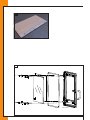
!CAUTION If you are installing a built-in appliance take account of:
•
The minimum building-in dimensions according to Annex 2, Fig. 1.
5.7.1 Free-standing/design fires
5.7.1.1 Conversion from fire top connection to rear connection (if applicable).
The fire is supplied with a top connection for connecting the flue duct.
The top connection can be converted to a rear connection.
Ø
Ø
Ø
Ø
Ø
Ø
Ø
Ø
Ø
Ø
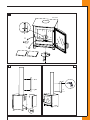
To do this proceed as follows (see Annex 2, Fig. 2):
Take the flame baffle plate or baffle plates out of the fireplace (if applicable see section 9, 'Appliance-specific
information').
Your appliance can be provided with an extra steel restrictor cap (if applicable see section 9, 'Appliance-specific
information'). Remove this by sliding the restrictor cap forwards and taking it out of the rails. This restrictor cap is
not replaced with a rear connection.
Remove the fire's convection back plate by undoing the bolts.
Remove the push-through plate from the convection back plate.
Remove the cover plate for the flue from the back wall of the fire by undoing the 2 or 3 nuts.
Remove the flue ring from the top plate by undoing the nuts and/or bolts.
Fit the flue ring on the back wall using the bolts and/or nuts.
Fasten the convection back plate again with the bolts.
Assemble the cover plate for the flue in the opening in the top plate using the nuts.
Replace the flame baffle plate or baffle plates in the reverse order.
5.7.1.2 Installing a free-standing fire, general
Ø
Ø
Ø
Ø
Ø
Ø
Ø
Ø
A free-standing fire is installed as follows:
Determine the fire location. The dimensions of the appliance are given in Annex 2, Fig. 1.
For any appliance-specific instructions we refer to section 9 'Appliance-specific information'.
Make sure there are no flammable materials present.
Lay the floor plate if applicable.
Place the fire on a blanket or sheet of cardboard (to avoid damaging the floor) then put it in the desired place.
Connect the fire to the flue duct. Follow the instructions of the supplier of the flue gas extraction system. Use
heater piping material that at least suffices with regard to EN 1856-2 T600.
Lift the fire a little if necessary so the blanket or cardboard can be removed.
For completing installation we refer to paragraph 5.8.
UK
INSTAL L ATIO N MA N U A L
5.7.1.3 Design fire installation
To install a design fire we refer to Section 9 'Appliance-specific information'.
5.7.2 Insert fires (existing and new situation)
English
5.7.2.1 With an existing chimney or chimney breast
Ø
Ø
Ø
Ø
Ø
Ø
Ø
Ø
Ø
Ø
Ø
Ø
Ø
Ø
Ø
Ø
Ø
Ø
Ø
Ø
Ø
Ø
Ø
Ø
Ø
!Caution
Ø
Ø
Ø
Ø
Ø
UK
To install an insert fire with an existing chimney or chimney breast proceed as follows:
Determine the fire location. The dimensions of the appliance are given in Annex 2, Fig. 1.
Leave a space of at least 10 mm between the fire and construction materials.
Check the size of the recess. If necessary the walls of the open hearth can be broken out a little. Make sure that the
chimney top is still sufficiently supported.
If applicable make room for the connection of the convection openings (if applicable see section 9
'Appliance-specific information') and section 5.3 'Convection')) with a flexible aluminium pipe and ventilation
elements (see section 5.4 'Appliances with fan(s)'. These accessories can be ordered from your supplier.
Be careful with the chimney breast plaster. Plaster beading makes the recess smaller.
Remove any existing valve from the open hearth or slide and clean the chimney top so all soot is removed.
Remove the fire door and disassemble the frame when it is supplied separately (see section 9 'Appliance-specific
information').
Carefully remove the vermiculite plates (mark them), the baffle plate and (if present) the restrictor cap from the
fire (if applicable see, section 9 'Appliance-specific information').
Lay any bottom plate supplied where the fire is to be installed.
Turn the adjustable legs in with the hexagonal socket screwdriver supplied and check whether they are properly
adjustable. There may still be some blasting grit present.
Make sure there is sufficient room under fire for the supply of combustion air when there is no outside air
connection.
An outside air connection can be made (if applicable see section 9 'Appliance-specific information').
Carefully slide the fire into the hole. Make sure that no damage is caused.
If applicable connect the convection opening ( see section 5.3 'Convection') with the flexible aluminium pipe and
ventilation elements (see section 5.4 'Appliances with fan(s))';
The fire may never support the flue.
Make a good, airtight seal between the fire and the flue, possibly with a register plate and preferably with a fixed
fire pipe or stainless steel double-walled flexible pipe that at least suffices with regard to standard EN 1856-2 T600.
If applicable, and depending on national regulations, the connection between the existing flue duct and the fire
may be plugged with heat-resistant ceramic wool
Proceed as follows:
Check whether the open hearth valve has been removed.
Remove the frame (if the frame is already fitted).
Remove the bottom plates and turn the fire as far as possible downwards with the adjustable legs to make space
for the ceramic wool.
Fill any space behind the fire with fire-resistant insulation material so no dirt can get in.
Remove the flame baffle plate.
Apply the ceramic wool between the top side of the fire and the chimney for an airtight connection.
Turn the fire up again with the adjustable legs and check whether the ceramic wool seals properly.
Replace the flame baffle plate (see section 9 'Appliance-specific information').
After the chimney has been swept always check that the connection is still airtight.
A handy kit is available through your supplier for the direct connection of a stainless steel flexible pipe to the fire.
The use of a kit is, however, not required for all appliances (if applicable see section 9 'Appliance-specific
information').
After the fire has been connected turn the adjustable legs with the Allen key supplied until the fire is in the
desired position. Make sure that the combustion air supply is not blocked.
Replace the restrictor cap for the outflow, fit the inner lining plates in reverse order and place the baffle plate
against the back wall and on the profiles (if applicable see section 9 'Appliance-specific information').
Use a torch or a thin screwdriver to check that the secondary ventilation holes in the back wall are directly facing
the recesses in the interior lining.
If applicable replace the frame around the fire (if applicable see section 9 'Appliance-specific information').
INST AL L AT I ON M AN U A L
5.7.2.2 In a new situation
Ø
Ø
Ø
Ø
Ø
Ø
Ø
Ø
Ø
Ø
Ø
Ø
Ø
Ø
Ø
Ø
Ø
Ø
Ø
Ø
Ø
Ø
Ø
Ø
Ø
Ø
Ø
Ø
Ø
Ø
Ø
Ø
Ø
Ø
To install an insert fire with a newly built chimney breast proceed as follows:
Determine the fire location. The dimensions are given in Annex 2, Fig. 1.
Place the fire on a floor with a sufficient load bearing capacity.
If applicable make a recess for an outside air connection (if applicable see section 9 'Appliance-specific
information').
Use non-combustible and heat-resistant material according to European fire classification A1 EN 13501-1 for the
plate on the floor, chimney breast (including the upper face), the material in the chimney breast and the back wall
against which the appliance is fitted. Plate material or stony materials can be used for this.
Leave a space of at least 10 mm between the fire and construction materials.
Be careful with the chimney breast plaster. Plaster beading makes the recess smaller.
Take account of the expansion of the fire. Keep the fire free of plasterwork.
If there is a flammable ceiling, place a fire-resistant plate with a 10 cm thick heat-insulating layer on top 30 cm
below the ceiling in the chimney breast.
If are there flammable materials (e.g. wooden floor parts/beams etc.) below or behind the fire, sufficient
non-combustible insulation material according to European fire classification A1 EN 13501-1 must be applied.
Comply with national regulations here.
If there is a flammable wall build a 10 cm-thick fire-safe wall.
Build the base or elevation with heat resistant material.
Place the steel plate supplied in the place for the fire. If applicable make a recess in it for the outside air
connection. Remove the fire door and disassemble the frame when it is supplied separately.
Remove the fire door and disassemble the frame when it is supplied separately (see section 9 'Appliance-specific
information').
Install the fire.
If applicable connect the outside air connection (see section 9 'Appliance-specific information').
If applicable connect the convection opening (see section 5.3 'Convection') with the flexible aluminium pipe and
ventilation elements (see section 5.4 'Appliances with fan(s))'.
Keeps these elements at least 30 cm away from the ceiling.
Use single-walled stainless steel flue pipes or stainless steel double-walled flexible pipes that at least meet the
requirements of standard EN 1856-2 T600.
The fire may never support the flue.
After the fire has been connected turn the adjustable legs with the Allen key supplied until the fire is in the
desired position. Make sure that the combustion air supply is not blocked when doing this.
Replace the restrictor cap for the outflow, fit the inner lining plates in reverse order and place the baffle plate
against the back wall and on the profiles (see section 9 'Appliance-specific information').
Use a torch or a thin screwdriver to check that the secondary ventilation holes in the back wall are directly facing
the recesses in the interior lining.
Replace the door and if applicable the frame around the fire (if applicable see section 9 'Appliance-specific
information').
Lay a fire-resistant floor plate for the fire if the floor is flammable. The floor plate of non-flammable material must
extend at least 300 mm away from the fire and be at least 300 mm wider than the fire.
English
Ø
Ø
Ø
Installing with build-in cassette (if applicable):
Place the fire with build-in cassette on a floor with a sufficient load bearing capacity.
Install the build-in cassette for a fire-safe wall.
If there is a flammable wall build a 10 cm-thick fire-safe wall.
Place the build-in cassette level at the desired height and fix it with metal anchors.
With a corner model fix the tie rod to the wall and adjust it.
Connect the flue duct to the cassette ring.
The cassette is not suitable for supporting a flue duct; this must be self-supporting.
Use non-combustible and heat-resistant material according to European fire classification A1 EN 13501-1 for the
chimney breast (including the upper face), the material in the chimney breast and the back wall against which the
appliance is fitted. Plate material or stony materials can be used for this.
If the chimney breast is made of heat-resistant plates according to European fire classification A1 EN 13501-1 such
as Promafour, Promatect, Nobranda etc., it can be fixed to the cassette.
Stony materials may not rest on the cassette; for this use a brick lintel with ceramic felt.
Leave a space of 6 mm between the cassette and the chimney breast walls.
Cover the cassette with 6 cm of heat-resistant insulation material.
Take account of the expansion of the cassette. Keep the cassette free of plasterwork.
The chimney breast may not be warmer than 90 degrees Celsius on the outside.
UK
Ø
Ø
Ø
Ø
Ø
Ø
Ø
Ø
Ø
Ø
If there is a flammable ceiling, place a fire-resistant plate with a 10 cm thick heat-insulating layer on top 30 cm
below the ceiling in the chimney breast.
Place the fire before the build-in cassette.
Turn in the adjustable legs and check whether they are properly adjustable. There may still be some blasting grit
present.
Carefully slide the fire into the hole. Make sure that no damage is caused.
Turn the adjustable legs with the associated Allen key so the fire comes into the desired position. Make sure that
sufficient space remains under the fire for the supply of combustion air.
Make a good, airtight seal between the fire and the flue.
Leave a space of at least 10 mm between the fire and cassette.
If applicable fit the restrictor cap for the outflow, place the vermiculite plates in reverse order and place the baffle
plate against the back wall and on the profiles.
Fit the frame if it is supplied separately.
Lay a fire-resistant floor plate for the fire if the floor is flammable. The floor plate in non-flammable material must
extend at least 300 mm away from the fire and be at least 300 mm wider than the fire.
5.7.3 Built-in fires
Ø
Ø
Ø
Ø
Ø
Ø
Ø
Ø
Ø
Ø
Ø
Ø
Ø
Ø
Determine the place of the fire.
Slide the build-in frame into the desired position.
Use non-combustible and heat-resistant material according to European fire classification A1 EN 13501-1 for the
plate on the floor, chimney breast (including the upper face), the material in the chimney breast and the back wall
against which the appliance is fitted. Plate material or stony materials can be used for this.
If there is a flammable ceiling, place a fire-resistant plate with a 10 cm thick heat-insulating layer on top 30 cm
below the ceiling in the chimney breast.
Place the fire level at the desired height and fix it with metal anchors.
Connect the flue duct to the fire ring.
Always connect any convection openings (see section 5.3 'Convection') with heat-resistant flexible pipe and
ventilation elements (see section 5.4 'Appliances wit fan(s)) to protect the plasterwork against high temperatures.
If the chimney breast is made of non-combustible materials (e.g. facing brickwork) this is not required.
Make sure there is sufficient space under the fire for the supply of combustion air. When the outside air
connection ring is not used, it must remain at least 20 mm free for sufficient combustion air.
If applicable connect the outside air connection (see section 9 'Appliance-specific information').
The fire is not suitable to support a flue duct, it must be self-supporting.
Stony materials may absolutely not rest on the fire. For this use e.g. a brick lintel with ceramic felt.
Make sure that the opening in the chimney breast is 6 mm wider than the built-in frame.
The chimney breast may not be warmer than 90 degrees Celsius on the outside;
Lay a fire-resistant floor plate for the fire if the floor is flammable. The floor plate in non-flammable material must
extend at least 300 mm away from the fire and be at least 300 mm wider than the fire.
5.8 Completing installation
Ø
Ø
Ø
Ø
Ø
Check if grit, dust or other materials are left behind in the chimney breast (odours).
Use clean fabric gloves and avoid fingerprints on the fire and flue pipes.
Check whether the interior lining and the baffle plates are fitted properly in the fire (if applicable see section 9
'Appliance-specific information'). Correct the position of these plates if necessary.
Check whether the holes of the secondary ventilation in the back plate are immediately facing the recesses in the
interior lining.
Clean the fire with a soft cloth and check it for damage. The fire can be sprayed with the spray can supplied.
Before doing this read the instructions for use on the label. Always first check the colour on a piece of white paper
or cardboard before you treat the fire.
First carefully read the user manual before starting to use the fire. We refer to the user manual for lighting and
burning the fire.
INSTAL L ATIO N MA N U A L
6. Delivery
Ø
You must make the user familiar with the fire. Among other things you must instruct her/him about bringing the
English
Ø
Ø
Ø
fire into use and its burning and maintenance.
When bringing into use point out that
•
after rebuilding or new building all building materials must have thoroughly dried out to avoid dust
(including smoke particles) adhering to damp surfaces;
•
the first time of burning volatile components will evaporate from paint, materials etc.;
•
the space must then be well ventilated.
Point out the necessity to have the flue duct inspected and cleaned at least once a year by a specialist.
Give the user the user manual and installation manual (the installation manual must be kept with the appliance).
7. Maintenance
The user manual includes a number of tips/instructions for maintenance of the fire. It also mentions how a
number of parts can be replaced.
8. Malfunctions
The user manual contains a table with a summary of malfunctions that can occur, their possible cause and the
solution.
UK
INST AL L AT I ON M AN U A L
9. Appliance-specific information
•
The appliance-specific instructions as described in this section prevail over the instructions in the other
sections! If in doubt follow the instructions in section 9 or contact your supplier.
The appliance-specific information as described in paragraphs 9.1 to 9.5 applies to all models described in
this manual. Supplementary installation instructions (per appliance) are described in paragraph 9.6.
English
!CAUTION •
9.1 Smoke control area United Kingdom
Ø
For more information on the appliances that have been recommended as suitable for use in smoke control areas
when burning wood we refer to http://smokecontrol.defra.gov.uk/appliances.php. In smoke control areas in the
United Kingdom the air slide valve may not be closed too far because of emission laws. A limiting screw is
accordingly supplied with all appliances. This is supplied as a kit in the combustion chamber. This screw is
therefore only used in the smoke control areas in the United Kingdom. In other countries this screw can be
disposed of in the appropriate way.
With the installation of an appliance in the United Kingdom:
Install the screw as shown in Appendix 2, fig. 3. After fitting, the air slide valve cannot be slid further shut
than legally allowed.
9.2 Air slide valve and flue gas exhaust
9.2.1 Air slide valve
When installing and maintaining the appliance, please check the operation of the air slide valve (see Appendix 2,
fig. 4). It is possible that steel grit entered the air slide valve during transport. If the air slide valve does not move
smoothly it must be cleaned. For this purpose, the air slide valve must be disassembled. The suspended air slide
valve is spring-mounted using a bolt and a spring, which are located below the cover plate.
Caution!
Ø
Ø
Ø
Caution!
Ø
When mounting the air slide valve, please proceed as follows (see Appendix 2, fig. 4):
If an outside air connection has been mounted, it must first be removed, before the air slide valve can be mounted
(for removing the outside air connection: see section 9.5).
Remove the vermiculite plates from the bottom (see section 9.3.1).
Then remove the little square plate located in a recess below the vermiculite bottom plates.
Loosen the allen screw using the socket head wrench.
As soon as the bolt has been loosened, the air slide valve will fall down. Make sure you catch the air slide valve!
Check the air slide valve and clean it if necessary.
In order to replace the air slide valve, proceed as described for removal, only in reverse order.
9.2.2 Flue gas exhaust
Ø
Ø
Ø
Ø
The flue gas exhaust has a 150 mm (6") diameter connection. The connection can be achieved by means of a fixed
pipe of 150 mm (6"). The flue gas exhaust can be connected at the top or rear of the appliance (see Appendix 2,
fig. 2).
In case of a connection at the rear, please proceed as follows:
Remove the 2 bolts from the exhaust ring mounted at the top of the appliance.
Remove the bolts from the plate at the rear of the appliance.
Mount this plate on the top of the appliance, on the location where the exhaust ring used to be.
Mount the exhaust ring at the rear of the appliance by tightening the 2 bolts.
UK
INSTAL L ATIO N MA N U A L
9.2.3 Heat shield (optional)
English
Using a heat shield will allow you to place the appliance closer to the wall. This 'heat shield kit' consists of two
guard plates and is optionally available through your supplier.
UK
Caution!
It is only possible to place a heat shield if the flue gas discharge is connected at the top of the appliance.
Ø
Ø
Ø
Proceed as follows:
Guard plate attached to the appliance:
Loosen the 4 pre-mounted bolts at the rear of the appliance by a few turns (see appendix 2, fig. 5).
Place the plate against the back of the appliance.
Tighten the 4 bolts.
Ø
Ø
Ø
Guard plate attached to the discharge pipe:
(only applicable in case of a single wall pipe)
Allow the guard plate to rest on the appliance at the rear of the flue duct.
Then press the plate against the flue duct.
Drill 4 holes (Ø 4 mm) and fix the plate using the supplied screws (see appendix 2, fig. 6).
INST AL L AT I ON M AN U A L
9.3 Interior lining
9.3.1 Vermiculite
!Caution
English
The fire's vermiculite plates are located on the bottom and against the rear and side walls of the appliance.
In the following situations the vermiculite plates must be taken out:
•
When disassembling the air slide valve (see section 9.2.1).
•
When replacing the vermiculite plates.
The bottom plates are removed first and the rear plates are removed last.
Make sure that the vermiculite plates are placed back in their original position! The back plate, for instance, must
be placed with the small, not countersunk, holes towards the front.
9.3.2 Flame baffle plate
On delivery the flame baffle plate (see Appendix 2, fig. 7) is located in the top section of the appliance.
In case of maintenance to the appliance, the flame baffle plate has to be removed.
Ø
Ø
Ø
To do this proceed as follows:
Take hold of the flame baffle plate and push the right side upwards.
Slide the flame baffle plate over the ridge to the right.
Lower the left side of the flame baffle plate and remove the flame baffle plate.
!Caution
Placing the flame baffle plate takes place in reverse order.
The stainless steel profile must be placed at the front with the screw heads on top (see Appendix 2, fig. 7).
UK
9.4 Door
Ø
Ø
Check the closing of the door during installation or maintenance.
To do this proceed as follows:
Check the sealing of the door by placing a sheet of paper between the door and the fire. After closing the door, it
should not be possible to pull out the sheet of paper easily. Check the outside of the fire.
In case the door still doesn't seal properly:
Replace the door seal (see section 9.4.1)
9.4.1 Replacing door seal
Ø
Ø
Ø
Ø
Proceed as follows when replacing the door seal:
Remove the door seal by taking it out of the integrated groove.
Remove excess kit residues from the door seal groove.
Use a heat-resistant kit to apply a new layer of kit in the groove.
Place the new door seal.
9.5 Glass pane
9.5.1 (Dis)assembly of the glass pane
!Caution
!Tip
Ø
Ø
Ø
Ø
Ø
Ø
!Caution
•
Avoid damage when removing/fitting the glass pane.
•
Avoid/remove fingerprints on the glass pane(s) as they will burn into the glass.
Use the supplied glass pane cleaner to remove fingerprints from the glass pane(s).
To remove the glass pane and then remount it in the door, please follow the instructions below
(see Appendix 2, fig. 8).
Disassembly of glass pane in door:
Open the door.
Lift out the door by sliding it upwards.
Place the door on a flat surface.
Unscrew the 4 bolts that hold the clamps.
Lift out the glass pane. The pane seal is also taken out.
Assembly of glass pane in door:
Mount the glass pane and place back the door by performing the steps for disassembling the glass pane in
reverse order.
•
•
Do not fasten the bolts too tight to avoid breaking off and/or stripping: overtightening will cause breakage.
Place the glass pane (including new pane seal) with the logo to the bottom right.
9.6 Supplementary installation instructions per appliance
9.6.1 Ivar 8 LowEA
9.6.1.1 Outside air connection
Outside air connections are available for these appliances as accessories. Assembly always takes place at the
bottom of the appliance. In case of these appliances, exhaust is only possible via the rear.
Ø
Ø
Ø
Ø
Ø
Caution!
When mounting the outside air connection, please proceed as follows (see Appendix 2, fig. 9a + 9b):
Loosen the 5 bolts that are pre-mounted on the outside air connection.
Bring the outside air connection against the plate on the bottom of the appliance.
Then re-tighten the 5 bolts.
Fasten the tray for the benefit of the rear connection with 4 bolts.
Connect the flexible hose to the round ‘pipe opening’ of the above-mentioned tray.
The flexible hose can only be fed from the rear.
The round pipe opening for the benefit of the lower connection is not needed during installation and should be
disposed of responsibly.
INSTAL L ATIO N MA N U A L
9.6.2 Ivar 8 StoreEA
9.6.2.1 Outside air connection
English
Outside air connections are available for these appliances as accessories. Assembly always takes place at the
bottom of the appliance. In case of these appliances, exhaust is only possible via the rear.
When mounting the outside air connection, please proceed as follows (see Appendix 2, fig. 10a + 10b):
Unscrew the 4 screws of the reflection plate and remove the plate. The reflection plate is located under the air
slide and protects the wood stacked below the stove against the high temperatures created in the appliance.
Ø
Break out the plate at the back of the appliance with a hammer.
Ø
Loosen the 5 bolts that are pre-mounted on the outside air connection.
Ø
Bring the outside air connection against the plate on the bottom of the appliance.
Ø
Then re-tighten the 5 bolts.
Ø
Fasten the tray for the benefit of the rear connection with 4 bolts.
Ø
Connect the flexible hose to the round ‘pipe opening’ of the above-mentioned tray.
The flexible hose can only be fed from the rear.
Caution! The round pipe opening for the benefit of the lower connection is not needed during installation and should be
disposed of responsibly.
CAUTION! Always place back the reflection plate!.
Ø
UK
INST AL L AT I ON S AN L E I T U N G
INHALT
Deutsch
1. Einleitung
2. EG-Konformitätserklärung
3. SICHERHEIT
3.1 Allgemein
3.2 Vorschriften
3.3 Schutzmaßnahmen/Sicherheitsanweisungen im Zusammenhang mit der Installation
4. Auspacken
5. Installation
5,1 Vorschriften
5.2 Rauchgasabzug
5.3 Landespezifische Installationsanforderungen
5.4 Aufstellen des Kamins
5.4.1 Freistehende Kamine / Designkamine
5.4.2 Einsatzkamine (bestehende und neue Situation)
5.4.3 Einbaukamine
5.5 Vollenden der Installation
6. Übergabe
7. Wartung
8. Störungen
9. Gerätespezifische Informationen
9.1 Luftschieber und Rauchgasabzug
9.1.1 Luftschieber
9.1.2 Rauchgasabzug
9.1.3 Hitzeschild (optional)
9.2 Innenauskleidung
9.2.1 Vermiculit
9.2.2 Flammenleitwand
9.3 Der Tür
9.3.1 Austauschen der Türdichtung
9.4 Scheibe
9.4.1 Ein/Ausbauen der Scheibe in die Tür
9.5 Ergänzende Installationsanweisungen für einzelne Geräte
9.5.1 Ivar 8 Low EA
9.5.1.1 Außenluftanschluss
9.5.2 Ivar 8 Store EA
9.5.2.1 Außenluftanschluss
Anlage 1: Im Lieferumfang enthaltene Teile
Anlage 2: Technische Daten
DE
INSTAL L ATIO NSA N L E I TU N G
1. EINLEITUNG
Deutsch
Als Hersteller von Kaminöfen entwickelt und produziert DRU Verwarming Produkte konform den
höchstmöglichen Deutsch Qualitäts-, Leistungs- und Sicherheitsanforderungen. Diese mit Holz gefeuerten
Dik Geurts-Kaminöfen sind mit einem CE-Zeichen versehen, das nur von Kaminöfen geführt werden darf, die die
wesentlichen Anforderungen aus der europäischen Bauprodukterichtlinie erfüllen, unter anderem die
Anforderungen in Bezug auf Sicherheit, Umwelt und Energieverbrauch.
Gemeinsam mit dem Kamin werden eine Installationsanleitung und eine Bedienungsanleitung geliefert.
Als Installateur müssen Sie anerkannt und fachkundig auf dem Gebiet der mit Holz geheizten Geräte sein.
Die Installationsanleitung enthält Informationen, die Sie benötigen, um den Kamin so zu installieren, dass dieser
einwandfrei und sicher funktioniert.
Diese Anleitung befasst sich mit der Installation des Kamins und den dabei geltenden Vorschriften.
Darüber hinaus finden Sie darin die technischen Daten des Kamins.
Die Abbildungen finden Sie am Ende dieser Anleitung in der Anlage.
Lesen Sie die Installationsanleitung komplett und sorgfältig durch und verwenden Sie diese, bevor Sie den Kamin
installieren. Nehmen Sie bei Fragen oder Zweifel immer Kontakt mit Ihrem Lieferanten auf.
Die Bedienungsanleitung enthält Informationen, die Sie benötigen, um das Gerät einwandfrei und sicher
funktionieren zu lassen. Lesen Sie die Bedienungsanleitung sorgfältig durch, bevor Sie den Kamin in Gebrauch
nehmen.
In den Anleitungen werden die folgenden Kennzeichnungen verwendet, um wichtige Informationen anzugeben:
Auszuführende Handlungen
!Tipp
Vorschläge und Empfehlungen
!Achtung Diese Anweisungen müssen eingehalten werden, um eventuelle Probleme bei der Installation und/oder
Verwendung zu verhindern.
!ACHTUNG Diese Anweisungen müssen eingehalten werden, um Brand, Verletzungen oder andere schwere Schäden zu
verhindern.
Ø
Nach der Übergabe müssen Sie die Bedienungsanleitung und diese Installationsanleitung an den Benutzer
überreichen.
Der Benutzer muss die Bedienungsanleitung und die Installationsanleitung sorgfältig aufbewahren.
DE
INST AL L AT I ON S AN L E I T U N G
2. EG-Konformitätserklärung
Deutsch
Der Unterzeichner im Auftrag des:
Herstellers
DRU Verwarming BV
Postbus 1021
NL-6920 BA Duiven
Ratio 8, NL-6921 RW Duiven
erklärt hiermit, dass das von DRU auf den Markt gebrachte, mit Holz gefeuerte Heizgerät durch seinen Entwurf
und seine Bauweise den wesentlichen Bestimmungen der Bauprodukterichtlinie entspricht und dass dieses Gerät
in Übereinstimmung mit den Anforderungen aus der belgischen königlichen Verordnung (Belgisch koninklijk
besluit) vom 12. Oktober 2010 in Bezug auf die Regelung der minimalen Anforderung an Wirkungsgrad und
Emissionsniveaus von verunreinigenden Stoffen für Heizgeräte für feste Brennstoffe ist.
Produkt:
Typ:
Geltende EG-Richtlinien:
Zugrunde liegende harmonisierte Normen:
Notified Body:
Holzheizgerät
Ivar 8 LowEA
89/106/EEC
NEN-EN-13240, NEN-EN-13240/A2
S.G.S. Nederland B.V. Reg.nr. 0608
Produkt:
Typ:
Geltende EG-Richtlinien:
Zugrunde liegende harmonisierte Normen:
Notified Body:
Holzheizgerät
Ivar 8 StoreEA
89/106/EEC
NEN-EN-13240, NEN-EN-13240/A2
S.G.S. Nederland B.V. Reg.nr. 0608
Kennzeichnende Produkteigenschaften / technische Daten sind in Anlage 1, Tabelle 2 am Ende der Anleitung
enthalten. Durch betriebsinterne Maßnahmen ist sichergestellt, dass serienmäßig hergestellte Geräte die
grundlegenden Anforderungen der geltenden EG-Richtlinien sowie der davon abgeleiteten Normen erfüllen.
Diese Erklärung verliert ihre Gültigkeit, wenn ohne die schriftliche Genehmigung von DRU Änderungen am Gerät
vorgenommen werden.
Im Namen von DRU Verwarming B.V.
M.J.M Gelten
Generaldirektor
DE
INSTAL L ATIO NSA N L E I TU N G
3. SICHERHEIT
3.1 Allgemein
Deutsch
!ACHTUNG •
•
Lesen Sie dieses Kapitel über Sicherheit unbedingt sorgfältig durch, bevor Sie mit der Installation oder
Wartung beginnen.
Die allgemein geltenden Vorschriften und die Schutzmaßnahmen/Sicherheitsanweisungen in dieser
Anleitung sind unbedingt einzuhalten.
3.2 Vorschriften
Das Gerät muss in Übereinstimmung mit den geltenden europäischen, nationalen, lokalen und baulichen
(Installations-) Vorschriften installiert werden. In den Niederlanden gilt unter anderem der „Bouwbesluit“
(Bauerlass).
3.3 Schutzmaßnahmen/Sicherheitsanweisungen im Zusammenhang mit der
Installation
Ø
Ø
Ø
Ø
Ø
Ø
Ø
Ø
Ø
Ø
Ø
Ø
Ø
Ø
Ø
Ø
Ø
Ø
Ø
Ø
Ø
Ø
Ø
Ø
DE
Halten Sie die folgenden Schutzmaßnahmen/Sicherheitsanweisungen genau ein:
Der Kamin darf ausschließlich von sachkundigen Installateuren auf dem Gebiet von mit Holz geheizten Geräten
installiert und gewartet werden.
Stellen Sie den Kamin nur in einem Raum auf, in dem der Standort, die bautechnische Konstruktion und die
Aktivitäten in dem Raum keine Gefahr für das Brennen des Kamins darstellen.
Stellen Sie den Kamin je nach dem Aufhängungstyp auf den Boden, gegen eine Wand oder unter eine Decke mit
einer ausreichenden Tragfähigkeit.
Berücksichtigen Sie eventuell vorhandene brennbare Balken vom Kaminsims, die sich über dem Kamin befinden.
Entfernen Sie diese oder bringen Sie konform der Bauverordnung ausreichend feuerfestes Isolationsmaterial
nach Eurobrandklasse A1 EN 13501-1 an.
Bringen Sie, wenn Sie noch weitere brennbare Materialien antreffen, konform der Bauverordnung ausreichend
feuerfestes Isolationsmaterial nach Eurobrandklasse A1 EN 13501-1 an.
Halten Sie beim Aufstellen eines freistehenden Kamins den erforderlichen Mindestabstand zwischen dem Kamin
und einer feuerfesten Wand ein. Dieser Abstand beträgt 50 mm.
Verwenden Sie Ofenrohrmaterial, das mindestens die Norm EN 1856-2 T600 erfüllt.
Berücksichtigen Sie beim Positionieren des Kamins und/oder der Ofenrohre den Mindestabstand zu brennbaren
Gegenständen und Materialien (siehe Anlage 1, Tabelle 2 und das Typenschild am Anfang in dieser Anleitung).
Legen Sie bei einem brennbaren Fußboden eine schützende Bodenplatte auf den Boden (siehe Kapitel 5.4).
Decken Sie einen freistehenden Kamin nicht ab und/oder verpacken Sie diesen nicht in eine Isolationsdecke oder
irgendein anderes Material.
Schließen Sie den Kamin an einen geeigneten Rauchgasabzug an.
Entfernen Sie die eventuell vorhandene Verschlussklappe oder schieben Sie den Rauchgasabzug in den
bestehenden Kamin.
Lassen Sie den Rauchgasabzug im Voraus durch einen anerkannten Schornsteinfeger inspizieren und reinigen.
Bringen Sie selbst keine Änderungen am Kamin an.
Verwenden Sie ausschließlich originale Ersatzteile.
Sorgen Sie für eine ausreichende Lüftung in dem Raum, in dem der Kamin aufgestellt wird; bringen Sie
gegebenenfalls eine zusätzliche Luftzufuhröffnung an.
Sorgen Sie dafür, dass im Raum, in dem der Kamin aufgestellt wird, niemals Unterdruck entsteht. Schließen Sie
den Außenluftanschluss an (wenn zutreffend) und leite damit die Verbrennungsluft direkt aus der Wohnung ab.
Zusätzliche Informationen für den Fall, dass Sie ein Einsatz-/Einbaugerät installieren:
Verwenden Sie feuerfestes und hitzebeständiges Material konform Eurobrandklasse A1 EN 13501-1 für den
Kaminumbau (inklusive der Oberseite des Kaminumbaus), für das Material im Kaminumbau und die Rückwand,
gegen welche das Gerät gestellt wird. Dafür können Plattenmaterialien oder steinartige Materialien verwendet
werden.
Ergreifen Sie ausreichende Maßnahmen konform den Bauverordnungen, um zu hohen Temperaturen (>85 °C)
einer Wand hinter dem Kaminumbau, inklusive der Materialien und/oder der Gegenstände, die sich hinter der
Wand befinden, vorzubeugen.
Berücksichtigen Sie die minimal vorgeschriebenen Innenabmessungen des Kaminsimses.
Mithilfe von Lüftungsgittern kann zusätzliche Konvektionswärme aus dem Kaminsims gewonnen werden.
Schließen Sie (wenn zutreffend) die Konvektionsöffnung mit einem flexiblen Aluminiumrohr und den
Lüftungselementen an.
Diese sind als Zubehör bei Ihrem Lieferanten zu bestellen.
Verwenden Sie (wenn zutreffend) hitzebeständige elektrische Anschlüsse, Positioniere diese frei vom Gerät.
INST AL L AT I ON S AN L E I T U N G
4. Auspacken
Beachten Sie beim Auspacken die folgenden Punkte:
Kontrollieren Sie das Gerät mit dem Zubehör auf (Transport-) Schäden.
Installieren Sie niemals einen beschädigten Kamin!
Nehmen Sie gegebenenfalls Kontakt mit Ihrem Lieferanten auf.
Deutsch
Ø
Ø
Ø
!ACHTUNG Halten Sie die Kunststoffverpackung von Kindern fern.
Ø
Ø
Ø
Ø
Ø
Ø
In Anlage 1, Tabelle 1, ist angegeben, über welche Teile Sie nach dem Auspacken verfügen müssen.
Auch transporttechnischen Gründen liegt die Flammenleitwand bei einigen Geräten auf dem Boden des Kamins.
Informationen zum Einsetzen dieser Flammenleitwand finden Sie (wenn zutreffend) in Kapitel 9
„Gerätespezifische Informationen“.
Durch den Transport können Teile verschoben sein. Kontrollieren Sie die Position der Leitwände und der Platten
der Innenauskleidung.Kontrollieren Sie vor dem Aufstellen die Funktion vom Luftschieber, vom Türverschluss
und vom eventuellen Drehmechanismus.
Informationen zum Einbauen/Ausbauen dieser Teile finden Sie (wenn zutreffend) in Kapitel 9 „Gerätespezifische
Informationen“.
Entfernen Sie das eventuell zurückgebliebene Strahlgut aus dem Luftschieber.
Nehmen Sie gegebenenfalls Kontakt mit Ihrem Lieferanten auf.
Entsorgen Sie die Verpackung auf regulärem Weg.
DE
INSTAL L ATIO NSA N L E I TU N G
5. Installation
Lesen Sie die Anleitung sorgfältig durch, um eine gute und sichere Installation des Geräts zu gewährleisten.
5.1 Vorschriften
Deutsch
Ø
Ø
Ø
Der Kamin muss in Übereinstimmung mit den geltenden europäischen, nationalen, lokalen und baulichen
(Installations-) Vorschriften installiert werden.
Halten Sie die in dieser Anleitung enthaltenen Anweisungen genau ein.
DRU Verwarming übernimmt keine Garantie für die Installation und die Wartung des Kamins und ist nicht für
eventuell dadurch entstehende Folgeschäden verantwortlich.
5.2 Rauchgasabzug
Ø
Ø
Ø
Ø
Ø
Ø
Ø
Ø
Ø
Ø
Ø
Ø
Ø
Ø
Ø
Für den Rauchgasabzug gelten die folgenden Anforderungen:
Der Rauchgasabzug muss im Voraus von einem Spezialisten inspiziert werden.Der Rauchgasabzug muss für das
Feuern mit einem mit Holz geheizten Gerät geeignet sein.
Der Kamin muss an einen einfachen, ungeteilten Rauchgasabzug angeschlossen werden.
Der Rauchgasabzug muss sauber und absolut dicht (leckagefrei) sein.
Verwenden Sie für den Rauchgasabzug Material, das mindestens die Norm EN 1856-1 T450 erfüllt.
Verwenden Sie für das Ofenrohr Material, das mindestens die Norm EN 1856-2 T600 erfüllt.
Die Auslenkung (Schrägführung) im Rauchgasabzug darf maximal 1,5 Meter betragen, mit einem Mindestwinkel
von 45 Grad zur Horizontalen, vorausgesetzt, der Zug im Abzug ist nicht zu niedrig.
Bei einem Anschluss auf der Rückseite darf der horizontale Teil des Rauchgasabzugs maximal 500 mm betragen.
Bei Verwendung des Anschlusses auf der Rückseite des Kamins an einen vertikalen Rauchgasabzug muss ein
T-Stück mit Rußfänger angebracht werden.
Der Durchmesser dieses Rauchgasabzugkanals muss mindestens dem Durchmesser des Rauchgasabzugs des
Kamins entsprechen.
Der Zug des Rauchgasabzugs muss mindestens 12 Pascal betragen.
Bringen Sie eventuell einen Rauchgasventilator an, wenn zu wenig Zug vorhanden ist oder wenn durch die
mechanische Lüftung in der Wohnung Unterdruck in dem Raum entsteht, in dem das Gerät aufgestellt wird.
In einem (zu) stark ziehenden Abzug (30 - 40 Pa) muss gegebenenfalls eine Drosselklappe angebracht werden.
Mit dieser Klappe kann der Zug geregelt werden. Das Gerät kann mit einem „Zugbegrenzer“ ausgeführt werden,
um einen eventuellen starken Zug zu begrenzen (siehe (wenn zutreffend) Kapitel 9 „Gerätespezifische
Informationen“).
Verwenden Sie beim Anbringen eines flexiblen Rohrs immer die doppelwandige Edelstahlausführung mit einer
„glatten“ Innenseite.
Um Rostbildung und eine Beschädigung der Innenauskleidung des Kamins durch Feuchtigkeit zu
einzuschränken, muss oben auf dem Rauchgasabzug eine Regenhaube angebracht werden.
Der Rauchgasabzug muss selbsttragend ausgeführt sein und darf nicht auf dem Kamin ruhen.
5.3 Konvektion
Beim Installieren eines Geräts in einem hohlen Kaminumbau müssen Konvektionsöffnungen realisiert werden.
Öffnen Sie (wenn zutreffend) die eventuell auf dem Gerät vorhandenen Konvektionsöffnungen wie beschrieben
in Kapitel 9 „Gerätespezifische Informationen“. Wenn auf dem Gerät keine Konvektionsöffnungen vorhanden
sind, müssen Sie die notwendige Be- und Entlüftung des Kaminumbaus selbst realisieren. Gehen Sie dabei von
einer minimalen Entlüftung des Kaminumbaus von 200 cm2 (an der Oberseite) und einer minimalen Belüftung
des Kaminumbaus von 200 cm2 (an der Unterseite) aus. Bringen Sie die Entlüftung an der Oberseite mindestens
30 cm unter der Decke und mindestens 180 cm über dem Fußboden an.
5.4 Geräte mit Ventilator(en)
Geräte, die mit einem oder mehreren Ventilatoren ausgeführt sind, heizen einen Raum schneller und damit
erhöht sich der Komfort. Wenn der Ventilator eingeschaltet wird, ist ein angenehm warmer Luftstrom zu spüren.
Der Ventilator kann auf verschiedene Stände eingestellt werden. Der Luftstrom kann das Gerät an der Vorderseite
und über die Konvektionsöffnungen im Gerät verlassen. Weitere Informationen zu Geräten mit Ventilator finden
Sie in Kapitel 9 „Gerätespezifische Informationen“.
5.5 Landespezifische Installationsanforderungen
Ø
DE
Das Gerät muss in Übereinstimmung mit den geltenden europäischen, nationalen, lokalen und baulichen
(Installations-) Vorschriften installiert werden.
In den Niederlanden gilt unter anderem der „Bouwbesluit“ (Bauerlass).
INST AL L AT I ON S AN L E I T U N G
5.6 Außenluftanschluss (wenn zutreffend)
Deutsch
Einige Kamine können mit einem Außenluftanschluss ausgerüstet werden. Für eine optimale Funktion des Geräts
sind folgende Punkte zu berücksichtigen, wenn ein Außenluftanschluss vorhanden ist:
•
Der Durchlass des Außenluftanschlusses und eventuell der Durchlass eines Lüftungsgitters darf nicht kleiner
als der Durchlass des Außenluftanschlusses auf dem Kamin sein.
•
Dafür sorgen, dass max. 4 Pascal Unterdruck in der Verbrennungsluftzufuhrleitung entsteht. Wenn ein
höherer Unterdruck entsteht, funktioniert der Kamin nicht einwandfrei und es können (heiße) Rauchgase in
die Zufuhrleitung zurückströmen.
•
Vermeiden, dass die Außenluftzufuhr ein einem Unterdruckbereich an der Außenseite des Hauses montiert
wird. Gegebenenfalls eine Zufuhrleitung mit einem T-Stück zu 2 Seiten des Hauses anbringen.
•
Die Verbrennungsluftzufuhrleitung darf nicht höher als die Unterseite des Kamins angebracht werden; auf
diese Weise wird verhindert, dass Rauchgasen zurückströmen.
•
Die Verbrennungsluftzufuhrleitung, die an den Kamin angeschlossen wird, muss auch nicht-brennbarem
Material bestehen.
•
Der Kamin funktioniert gut mit einem flexiblen Rohr mit einer max. Länge von 11 Metern und 4 Bögen. Bei
größeren Längen oder mehr Bögen wird empfohlen, ein Rohr mit einem größeren Durchmesser (100-125
mm) zu verwenden.
•
Wenn ein Kriechschacht gut mithilfe von offenen Lüftungsgittern belüftet wird, darf die Verbrennungsluft
von dort angesaugt werden. Wenn keine gute Belüftung im Kriechschacht gewährleistet ist, können dort
schädliche Radongase angesaugt werden; dies ist nach den nationalen Vorschriften nicht zulässig.
Weitere Informationen über den Außenluftanschluss finden Sie (wenn zutreffend) in Kapitel 9 „Gerätespezifische
Informationen“.
5.7 Allgemeine Anweisungen zum Aufstellen des Kamins
!Achtung
•
•
•
•
Bringen Sie selbst keine Änderungen am Kamin an.
Ziehen Sie saubere Stoffhandschuhe an, vermeiden Sie Fingerabdrücke auf dem Kamin und den
Ofenrohren.
Stellen Sie den Kamin je nach dem Aufhängungstyp auf den Boden, gegen eine Wand oder unter eine Decke
mit einer ausreichenden Tragfähigkeit.
Legen Sie bei einem brennbaren Fußboden eine feuerfeste Bodenplatte auf den Boden. Die Bodenplatte aus
feuerfestem Material muss an der Vorderseite mindestens 300 mm unter dem Kamin herausragen und
mindestens 300 mm breiter sein als der Kamin. Kontrollieren Sie diese Abstände vor dem Aufstellen des
Kamins anhand der geltenden nationalen/lokalen Gesetze.
!Tipp
Eine Bodenplatte schützt gegen glühende Ascheteilchen und verhindert, dass z. B. ein Fußboden aus Marmor
oder Fliesen verschmutzt. Daher empfehlen wir immer, eine feuerfeste Bodenplatte zu verwenden, auch bei
Geräten, die an der Wand oder an der Decke montiert werden.
Ø
Kontrollieren Sie auf der Maßzeichnung des Kamins, welchen Ofenrohrdurchmesser Sie benötigen (siehe Anlage
1, Tabelle 2).
Verwenden Sie ein Ofenrohr, das mindestens die in EN 1856-2 T600 festgelegten Normen erfüllt.
Bringen Sie die Ofenrohre so an, dass niemals eine feuergefährliche Situation entstehen kann.
Halten Sie beim Aufstellen eines freistehenden Kamins den erforderlichen Mindestabstand zwischen dem Kamin
und einer feuerfesten Wand ein. Dieser Abstand beträgt 50 mm.
Halten Sie beim Aufstellen des Kamins und/oder dem Anbringen der Ofenrohre den Mindestabstand zu
brennbaren Gegenständen und Materialien ein, wie angegeben in Anlage 1, Tabelle 2.
Ergreifen Sie ausreichende Maßnahmen, um zu hohe Temperaturen einer eventuellen Wand hinter dem
Kaminsims zu verhindern.
Dies gilt auch für Materialien und/oder Gegenstände, die sich hinter der Wand befinden.
Halten Sie die Anforderungen in Bezug auf den Rauchgasabzug ein, wie beschrieben in Abschnitt 5.2.
Ø
Ø
Ø
Ø
Ø
Ø
Informationen zu eventuellen gerätespezifischen Anweisungen finden Sie in Kapitel 9 „Gerätespezifische
Informationen“.
!ACHTUNG Berücksichtigen Sie Folgendes, wenn Sie ein Einbaugerät installieren:
•
Die minimalen Einbauabmessungen nach Anlage 2, Abb. 1.
DE
INSTAL L ATIO NSA N L E I TU N G
5.7.1 Freistehende Kamine / Designkamine
5.7.1.1 Umbauen von einem Anschluss an der Oberseite zu einem Anschluss auf der Rückseite
des Kamins (wenn zutreffend)
Deutsch
Der Kamin wird mit einem Anschluss für den Rauchgasabzug an der Oberseite geliefert.
Der Anschluss an der Oberseite kann gegebenenfalls zu einem Anschluss auf der Rückseite umgebaut werden.
Ø
Ø
Ø
Ø
Ø
Ø
Ø
Ø
Ø
Ø
Gehen Sie dazu wie folgt vor (siehe Anlage 2, Abb. 2):
Nehmen Sie die Flammenleitwand bzw. Leitwände aus der Feuerstelle (wenn zutreffend siehe Kapitel 9
,„Gerätespezifische Informationen“).
Ihr Gerät kann mit einem zusätzlichen Zugbegrenzer aus Stahl ausgeführt sein (wenn zutreffend siehe Kapitel 9,
„Gerätespezifische Informationen“). Entfernen Sie diesen Zugbegrenzer, indem Sie ihn nach vorne schieben und
aus den Schienen nehmen. Bei einem Anschluss auf der Rückseite wird dieser Zugbegrenzer nicht wieder
eingebaut.
Entfernen Sie die hintere Konvektionsplatte des Kamins, indem Sie die Schrauben lösen.
Entfernen Sie die vorgestanzte Platte aus der hinteren Konvektionsplatte.
Entfernen Sie die Abdeckplatten für den Rauchgasabzug aus der Rückwand des Kamins, indem Sie die 2 oder 3
Muttern lösen.
Entfernen Sie den Ring des Rauchgasabzugs aus der oberen Platte, indem Sie die Muttern und/oder Schrauben
lösen.
Montieren Sie den Ring des Rauchgasabzugs mit den Schrauben und/oder Muttern an der Rückwand.
Befestigen Sie die hintere Konvektionsplatte wieder mit den Schrauben.
Befestigen Sie die Abdeckplatte für den Rauchgasabzug mit den Muttern in der Öffnung in der oberen Platte.
Bringen Sie die Flammenleitwand bzw. die Leitwände in umgekehrter Reihenfolge wieder an.
5.7.1.2 Aufstellen eines freistehenden Kamins, allgemein
Ø
Ø
Ø
Ø
Ø
Ø
Ø
Ø
Beim Aufstellen des freistehenden Kamins gehen Sie wie folgt vor:
Bestimmen Sie den Aufstellort des Kamins. Die Abmessungen des Geräts finden Sie in Anlage 2, Abb. 1.
Informationen zu eventuellen gerätespezifischen Anweisungen finden Sie in Kapitel 9 „Gerätespezifische
Informationen“.
Sorgen Sie dafür, dass keine brennbaren Materialien vorhanden sind.
Legen Sie gegebenenfalls die Bodenplatte an die richtige Stelle.
Stellen Sie den Kamin zuerst auf eine Decke oder ein Stück Pappe (damit verhindern Sie eine eventuelle
Beschädigung des Bodens) und dann an die gewünschte Stelle.
Schließen Sie den Kamin an den Rauchgasabzug an. Befolgen Sie dabei die Anweisungen des Lieferanten des
Rauchgasabzugsystems. Verwenden Sie Ofenrohrmaterial, das mindestens die Norm EN 1856-2 T600 erfüllt.
Verschieben Sie den Kamin gegebenenfalls und kippen Sie diesen etwas, um die Decke oder die Pappe zu
entfernen.
Informationen zum Vollenden der Installation finden Sie in Abschnitt 5.8.
5.7.1.3 Aufstellen eines Designkamins
Informationen zum Aufstellen eines Designkamins finden Sie in Kapitel 9 „Gerätespezifische Informationen“.
5.7.2 Einsatzkamine (bestehende und neue Situation)
5.7.2.1 In einen bestehenden Kaminsims oder Kaminumbau
Ø
Ø
Ø
Ø
Ø
Ø
Ø
DE
Beim Einbauen eines Einsatzkamins in einen bestehenden Kaminsims oder Kaminumbau gehen Sie wie folgt vor:
Bestimmen Sie den Aufstellort des Kamins. Die Abmessungen des Geräts finden Sie in Anlage 2, Abb. 1.
Halten Sie mindestens 10 mm Abstand zwischen dem Kamin und Baumaterialien frei.
Kontrollieren Sie die Abmessung der Aussparung. Gegebenenfalls können die Wände für den Kamin noch etwas
ausgebrochen werden. Sorgen Sie dafür, dass die Rauchgasabzugshaube ausreichend unterstützt bleibt.
Schaffen Sie gegebenenfalls Platz für den Anschluss der Konvektionsöffnungen (wenn zutreffend siehe Kapitel 9
'Gerätespezifische Informationen' und Kapitel 5.3 'Konvenktion') mit einem flexiblen Aluminiumrohr und
Lüftungselementen. Diese sind als Zubehör bei Ihrem Lieferanten zu bestellen.
Seien Sie vorsichtig, wenn Sie den Kaminsims verputzen. Putzprofile machen die Aussparung kleiner.
Entfernen Sie die eventuell vorhandene Klappe des Kamins oder den Schieber und reinigen Sie die
Rauchgasabzugshaube, sodass kein Ruß zurückbleibt.
Entfernen Sie die Kamintür und bauen Sie den Einbaurahmen aus, wenn dieser separat mitgeliefert wurde (siehe
Kapitel 9 „Gerätespezifische Informationen“).
INST AL L AT I ON S AN L E I T U N G
Ø
Ø
Ø
Ø
Ø
Ø
Ø
Ø
Ø
Ø
Ø
Ø
Ø
Ø
Ø
Ø
Ø
!Achtung
Ø
Ø
Ø
Ø
Ø
Entfernen Sie die Vermiculitplatten (kennzeichnen Sie diese), die Leitwand und wenn vorhanden den
Zugbegrenzer vorsichtig aus dem Kamin (wenn zutreffend siehe Kapitel 9 „Gerätespezifische Informationen“).
Legen Sie die eventuell mitgelieferte Bodenplatte an die Stelle, an der der Kamin aufgestellt werden soll.
Drehen Sie die Stellfüße mit dem im Lieferumfang enthaltenen Innensechskantschraubendreher nach innen und
kontrollieren Sie, ob diese gut verstellbar sind. Es kann noch etwas Strahlgut vorhanden sein.
Sorgen Sie dafür, dass unter dem Kamin ausreichend Platz für die Zufuhr von Verbrennungsluft vorhanden ist,
wenn kein Außenluftanschluss verwendet wird.
Gegebenenfalls ist ein Außenluftanschluss möglich (wenn zutreffend siehe Kapitel 9 „Gerätespezifische
Informationen“).
Schieben Sie den Kamin vorsichtig in die Öffnung. Achten Sie darauf, dass keine Beschädigungen entstehen.
Schließen Sie (wenn zutreffend) die Konvektionsöffnung (siehe kapitel 5.3 'Konvektion') mit dem flexiblen
Aluminiumrohr und den Lüftungselementen (siehe Kapitel 5.4 'Geräte mit Ventilator(en)') an.
Der Kamin darf den Rauchgasabzug niemals tragen.
Bringen Sie eine gute, luftdichte Abdichtung zwischen dem Kamin und dem Rauchgasabzug an, eventuell mit
einer Registerplatte und vorzugsweise mit einem festen Ofenrohr oder einem doppelwandigen, flexiblen
Ofenrohr aus Edelstahl, das mindestens die Anforderungen aus der Norm EN 1856-2 T600 erfüllt.
Wenn zutreffend und abhängig von den nationalen Vorschriften darf die Verbindung zwischen dem
bestehenden Rauchgasabzug und dem Kamin mit hitzebeständiger Keramikwolle vollgestopft werden.
Gehen Sie wie folgt vor:
Kontrollieren Sie, ob die Klappe des alten Kamins entfernt wurde.
Entfernen Sie den Einbaurahmen (wenn dieser Rahmen bereits eingebaut wurde).
Entfernen Sie die Bodenplatten und drehen Sie den Kamin mit den Stellfüßen so weit wie möglich nach unten,
um Platz für die Keramikwolle zu schaffen.
Füllen Sie den eventuellen Raum hinter dem Kamin mit feuerfestem Isolationsmaterial auf, sodass kein Schmutz
dahinter gelangen kann.
Entfernen Sie die Flammenleitwand.
Bringen Sie Keramikwolle zwischen der Oberseite des Kamins und dem Schornstein an, sodass ein luftdichter
Anschluss entsteht.
Drehen Sie den Kamin mit den Stellfüßen wieder nach oben und kontrollieren Sie, ob die Keramikwolle gut
abdichtet.
Legen Sie anschließend die Flammenleitwand wieder an die richtige Stelle zurück (siehe Kapitel 9
„Gerätespezifische Informationen“).
Kontrollieren Sie jeweils nach dem Schornsteinfegen, ob der Anschluss noch luftdicht ist.
Für das direkte Anschließen eines flexiblen Edelstahlrohrs an den Kamin ist über Ihren Lieferanten ein praktisches
Kit erhältlich. Die Verwendung dieses Kits ist jedoch nicht bei allen Geräten erforderlich (wenn zutreffend siehe
Kapitel 9 „Gerätespezifische Informationen“).
Wenn der Kamin angeschlossen ist, drehen Sie die Stellfüße mit dem dazugehörigen Innensechskantschlüssel so
aus, dass der Kamin in der gewünschten Position steht. Sorgen Sie dafür, dass die Verbrennungsluftzufuhr dabei
nicht blockiert wird.
Bringen Sie den Zugbegrenzer wieder vor dem Ausgang an, setzen Sie die Platten der Innenauskleidung in
umgekehrter Reihenfolge wieder ein und legen Sie die Leitwand gegen die Rückwand und auf die Profile
(wenn zutreffend siehe Kapitel 9 „Gerätespezifische Informationen“).
Kontrollieren Sie mit einer Taschenlampe oder einem dünnen Schraubendreher, ob sich die Öffnungen der
sekundären Belüftung in der Rückwand gerade vor den Aussparungen in der Innenauskleidung befinden.
Bringen Sie gegebenenfalls den Rahmen um den Kamin wieder an (wenn zutreffend siehe Kapitel 9
„Gerätespezifische Informationen“).
Deutsch
Ø
DE
INSTAL L ATIO NSA N L E I TU N G
5.7.2.2 Bei einer neuen Situation
Deutsch
Ø
Ø
Ø
Ø
Ø
Ø
Ø
Ø
Ø
Ø
Ø
Ø
Ø
Ø
Ø
Ø
Ø
Ø
Ø
Ø
Ø
Ø
Ø
DE
Beim Einbauen eines Einsatzkamins in einen neu zu bauenden Kaminumbau gehen Sie wie folgt vor:
Bestimmen Sie den Aufstellort des Kamins. Die Abmessungen finden Sie in Anlage 2, Abb. 1.
Stellen Sie den Kamin auf einen Fußboden mit einer ausreichenden Tragfähigkeit.
Fertigen Sie gegebenenfalls eine Aussparung für einen Außenluftanschluss an (wenn zutreffend siehe Kapitel 9
„Gerätespezifische Informationen“).
Verwenden Sie feuerfestes und hitzebeständiges Material konform Eurobrandklasse A1 EN 13501-1 für die Platte
auf dem Boden, für den Kaminumbau (inklusive der Oberseite des Kaminumbaus), für das Material im
Kaminumbau und für die Rückwand, gegen welche das Gerät gestellt wird. Dafür können Plattenmaterialien oder
steinartige Materialien verwendet werden.
Halten Sie mindestens 10 mm Abstand zwischen dem Kamin und Baumaterialien frei.
Seien Sie vorsichtig, wenn Sie den Kaminsims verputzen. Putzprofile machen die Aussparung kleiner.
Berücksichtigen Sie dabei, dass sich der Kamin ausdehnt. Bringen Sie keinen Putz auf dem Kamin an.
Bringen Sie im Fall einer brennbaren Decke 30 cm unter der Decke im Kaminumbau eine feuerbeständige Platte
mit darauf einer 10 cm dicken wärmeisolierenden Schicht an.
Wenn brennbare Materialien (z. B. Holzdielen/Holzbalken usw.) unter oder hinter dem Kamin vorhanden sind,
muss ausreichend feuerfestes Isolationsmaterial konform Eurobrandklasse A1 EN 13501-1 angebracht werden.
Berücksichtigen Sie dabei die nationalen Vorschriften.
Bringen Sie bei einer brennbaren Wand eine 10 cm dicke feuerhemmende Wand an.
Bauen Sie das Plateau oder die Erhöhung aus hitzebeständigen Material auf.
Legen Sie die im Lieferumfang enthaltene Stahlplatte an die Stelle für den Kamin. Bringen Sie darin
gegebenenfalls eine Aussparung für den Außenluftanschluss an. Entfernen Sie die Kamintür und bauen Sie den
Einbaurahmen aus, wenn dieser separat mitgeliefert wurde.
Entfernen Sie die Kamintür und bauen Sie den Einbaurahmen aus, wenn dieser separat mitgeliefert wurde (siehe
Kapitel 9 „Gerätespezifische Informationen“).
Setzen Sie den Kamin ein.
Schließen Sie (wenn zutreffend) den Außenluftanschluss an (siehe Kapitel 9 „Gerätespezifische Informationen“).
Schließen Sie (wenn zutreffend) die Konvektionsöffnung (siehe Kapitel 5.3 'Konvektion') mit dem flexiblen
Aluminiumrohr und den Lüftungselementen (siehe Kapitel 5.4 'Geräte mit Ventilator(en)') an.
Halten Sie bei diesen Elementen einen Mindestabstand von 30 cm zur Decke ein.
Verwenden Sie einwandige Edelstahlofenrohre oder doppelwandige, flexible Edelstahlrohre, die mindestens die
Norm EN 1856-2 T600 erfüllen.
Der Kamin darf den Rauchgasabzug niemals tragen.
Wenn der Kamin angeschlossen ist, drehen Sie die Stellfüße mit dem dazugehörigen Innensechskantschlüssel so
aus, dass der Kamin in der gewünschten Position steht. Sorgen Sie dafür, dass die Verbrennungsluftzufuhr dabei
nicht blockiert wird.
Bringen Sie den Zugbegrenzer wieder vor dem Ausgang an, setzen Sie die Platten der Innenauskleidung in
umgekehrter Reihenfolge wieder ein und legen Sie die Leitwand gegen die Rückwand und auf die Profile (siehe
Kapitel 9 „Gerätespezifische Informationen“).
Kontrollieren Sie mit einer Taschenlampe oder einem dünnen Schraubendreher, ob sich die Öffnungen der
sekundären Belüftung in der Rückwand gerade vor den Aussparungen in der Innenauskleidung befinden.
Setzen Sie die Tür und wenn zutreffend den Rahmen um den Kamin wieder ein (wenn zutreffend siehe Kapitel 9
„Gerätespezifische Informationen“).
Legen Sie bei einem brennbaren Fußboden eine feuerfeste Bodenplatte vor den Kamin. Die Bodenplatte aus
feuerfestem Material muss an der Vorderseite mindestens 300 mm unter dem Kamin herausragen und
mindestens 300 mm breiter sein als der Kamin.
INST AL L AT I ON S AN L E I T U N G
Ø
Ø
Ø
Ø
Ø
Ø
Ø
Ø
Ø
Ø
Ø
Ø
Ø
Ø
Ø
Ø
Ø
Ø
Ø
Ø
Ø
Ø
Einbauen mit einmauerbarer Kaminkassette (wenn zutreffend):
Stellen Sie den Kamin mit der einmauerbaren Kaminkassette auf einen Fußboden mit einer ausreichenden
Tragfähigkeit.
Stellen Sie die einmauerbare Kaminkassette vor eine feuerhemmende Wand.
Bringen Sie bei einer brennbaren Wand eine 10 cm dicke feuerhemmende Wand an.
Richten Sie die einmauerbare Kaminkassette waagerecht in der richtigen Höhe aus und befestigen Sie diese mit
Metallankern.
Befestigen Sie die Zugstange bei einem Eckmodell an der Wand und richten Sie sie richtig aus.
Schließen Sie den Rauchgasabzug an den Ring der Kassette an.
Die Kassette ist nicht dazu geeignet, einen Rauchgasabzug zu tragen; dieser muss selbsttragend sein.
Verwenden Sie feuerfestes und hitzebeständiges Material konform Eurobrandklasse A1 EN 13501-1 für den
Kaminumbau (inklusive der Oberseite des Kaminumbaus), für das Material im Kaminumbau und die Rückwand,
gegen welche das Gerät gestellt wird. Dafür können Plattenmaterialien oder steinartige Materialien verwendet
werden.
Wenn der Kaminumbau aus hitzebeständigen Platten konform Eurobrandklasse A1 EN 13501-1, wie Promafour,
Promatect, Nobranda u. Ä., hergestellt werden, können diese an der Kassette befestigt werden.Steinartige
Materialien dürfen nicht auf der Kassette ruhen; verwenden Sie dafür einen Backsteinsturz mit keramischem Filz.
Lassen Sie 6 mm Platz zwischen der Kassette und den Wänden des Kaminumbaus frei.
Kleiden Sie die Kassette mit 6 cm dickem, hitzebeständigem Isolationsmaterial aus.
Berücksichtigen Sie dabei, dass sich die Kassette ausdehnt. Bringen Sie keinen Putz auf der Kassette an.
Der Kaminumbau darf an der Außenseite nicht wärmer als 90 Grad Celsius werden.
Bringen Sie im Fall einer brennbaren Decke 30 cm unter der Decke im Kaminumbau eine feuerbeständige Platte
mit darauf einer 10 cm dicken wärmeisolierenden Schicht an.
Stellen Sie den Kamin vor die einmauerbare Kaminkassette.
Drehen Sie die Stellfüße ein und kontrollieren Sie, ob diese gut verstellbar sind. Es kann noch etwas Strahlgut
vorhanden sein.
Schieben Sie den Kamin vorsichtig in die Öffnung. Achten Sie darauf, dass keine Beschädigungen entstehen.
Drehen Sie die Stellfüße mit dem dazugehörigen Innensechskantschlüssel so aus, dass der Kamin in der
gewünschten Position steht. Sorgen Sie dafür, dass unter dem Kamin ausreichend Platz für die Zufuhr von
Verbrennungsluft übrig bleibt.
Bringen Sie eine gute, luftdichte Abdichtung zwischen dem Kamin und dem Rauchgasabzug an.
Halten Sie mindestens 10 mm Abstand zwischen dem Kamin und der Kassette frei.
Bringen Sie gegebenenfalls den Zugbegrenzer wieder vor dem Ausgang an, setzen Sie die Vermiculitplatten in
umgekehrter Reihenfolge wieder ein und legen Sie die Leitwand gegen die Rückwand und auf die Profile.
Setzen Sie den Rahmen ein, wenn dieser separat mitgeliefert wurde.
Legen Sie bei einem brennbaren Fußboden eine feuerfeste Bodenplatte vor den Kamin. Die Bodenplatte aus
feuerfestem Material muss an der Vorderseite mindestens 300 mm unter dem Kamin herausragen und
mindestens 300 mm breiter sein als der Kamin.
Deutsch
Ø
DE
5.7.3 Einbaukamine
Ø
Ø
Ø
Ø
Ø
Ø
Ø
Ø
Ø
Ø
Ø
Ø
Ø
Ø
Bestimmen Sie den Aufstellort des Kamins.
Schieben Sie den Einbaurahmen in die gewünschte Position.
Verwenden Sie feuerfestes und hitzebeständiges Material konform Eurobrandklasse A1 EN 13501-1 für die Platte
auf dem Boden, für den Kaminumbau (inklusive der Oberseite des Kaminumbaus), für das Material im
Kaminumbau und für die Rückwand, gegen welche das Gerät gestellt wird. Dafür können Plattenmaterialien oder
steinartige Materialien verwendet werden.
Bringen Sie im Fall einer brennbaren Decke 30 cm unter der Decke im Kaminumbau eine feuerbeständige Platte
mit darauf einer 10 cm dicken wärmeisolierenden Schicht an.
Richten Sie den Kamin waagerecht in der richtigen Höhe aus und befestigen Sie diesen mit Metallankern.
Schließen Sie den Rauchgasabzug an den Ring des Kamins an.
Schließen Sie eventuelle Konvektionsöffnungen (siehe Kapitel 5.3 'Konvektion') immer mit einem
hitzebeständigen, flexiblen Rohr und Lüftungselementen (siehe Kapitel 5.4 'Geräte mit Ventilator(en)') an, um
den Putz vor hohen Temperaturen zu schützen. Wenn der Kaminumbau aus feuerfesten Materialien (z. B. aus
Mauersteinen) hergestellt ist, ist dies nicht erforderlich.
Sorgen Sie dafür, dass unter dem Kamin ausreichend Platz für die Zufuhr von Verbrennungsluft vorhanden ist.
Wenn der Ring des Außenluftanschlusses nicht verwendet wird, muss dieser für ausreichend Verbrennungsluft
mindestens 20 mm frei bleiben.
Schließen Sie (wenn zutreffend) den Außenluftanschluss an (siehe Kapitel 9 „Gerätespezifische Informationen“).
Der Kamin ist nicht dazu geeignet, einen Rauchgasabzug zu tragen; dieser muss selbsttragend sein.
Steinartige Materialien dürfen absolut nicht auf dem Kamin ruhen. Verwenden Sie dazu z. B. einen Backsteinsturz
mit keramischem Filz.
Sorgen Sie dafür, dass die Öffnung im Kaminumbau 6 mm größer ist als der Einbaurahmen.
Der Kaminumbau darf an der Außenseite nicht wärmer als 90 Grad Celsius werden.
Legen Sie bei einem brennbaren Fußboden eine feuerfeste Bodenplatte vor den Kamin. Die Bodenplatte aus
feuerfestem Material muss an der Vorderseite mindestens 300 mm unter dem Kamin herausragen und
mindestens 300 mm breiter sein als der Kamin.
5.8 Vollenden der Installation
Ø
Ø
Ø
Ø
Ø
Kontrollieren Sie, dass kein Schutt, Staub oder anderes Material im Kaminumbau zurückbleibt (wegen des
Gestanks).
Ziehen Sie saubere Stoffhandschuhe an und vermeiden Sie Fingerabdrücke auf dem Kamin und den Ofenrohren.
Kontrollieren Sie, ob die Innenauskleidung und die Leitwände richtig in den Kamin eingelegt wurden (wenn
zutreffend siehe Kapitel 9 „Gerätespezifische Informationen“). Verbessern Sie gegebenenfalls die Position dieser
Platten.
Kontrollieren Sie, ob sich die Öffnungen der sekundären Belüftung in der hinteren Platte gerade vor den
Aussparungen in der Innenauskleidung befinden.
Reinigen Sie den Kamin mit einem feuchten Tuch und kontrollieren Sie ihn auf Beschädigungen. Sprühen Sie den
Kamin eventuell mit der mitgelieferten Spraydose nach. Lesen Sie dazu die Gebrauchanweisung auf dem Etikett.
Kontrollieren Sie die Farbe immer zuerst auf einem Stück weißem Papier oder weißer Pappe, bevor Sie den Kamin
nachbessern.
Lesen Sie zuerst die Bedienungsanleitung aufmerksam durch, bevor der Kamin in Gebrauch genommen wird.
Informationen zum Anzünden oder Heizen des Kamins finden Sie in der Bedienungsanleitung.
INSTAL L ATIO NSA N L E I TU N G
6. Übergabe
Ø
Sie müssen den Benutzer mit dem Kamin vertraut machen. Sie müssen ihn/sie unter anderem in die
Deutsch
Ø
Ø
Ø
Inbetriebnahme, das Heizen und die Wartung des Kamins einweisen.
Weisen Sie bei der Inbetriebnahme darauf hin, dass
•
nach einem Umbau oder bei Neubau alle Baumaterialien richtig austrocknen, dies ist im Zusammenhang mit
dem Anhaften von Staub (u. A. Rauchteilchen) an feuchten Oberflächen wichtig;
•
beim ersten Mal Heizen flüchtige Komponenten aus dem Lack, den Materialien usw. ausdampfen;
•
der Raum gut gelüftet wird.
Weisen auf die Notwendigkeit hin, den Rauchgasabzug mindestens einmal pro Jahr von einem Spezialisten
inspizieren und reinigen zu lassen.
Händigen Sie dem Benutzer immer die Benutzeranleitung und die Installationsanleitung aus (die
Installationsanleitung muss bei dem Gerät aufbewahrt werden).
7. Wartung
Die Benutzeranleitung enthält eine Reihe von Tipps/Anweisungen für die Wartung des Kamins. Außerdem wird
darin beschrieben, wie eine Reihe von Teilen ausgetauscht werden kann.
8. Störungen
In der Benutzeranleitung steht eine Tabelle mit einer Übersicht der Störungen, die auftreten können, der
möglichen Ursache und der Lösung.
DE
INST AL L AT I ON S AN L E I T U N G
9. Gerätespezifische Informationen
•
Die gerätespezifischen Anweisungen aus diesem Kapitel haben Vorrang vor den Anweisungen in den
übrigen Kapiteln! Halten Sie sich bei Zweifel an die Anweisungen in Kapitel 9 oder nehmen Sie Kontakt mit
Ihrem Lieferanten auf.
Die gerätespezifischen Informationen, die in den Abschnitten 9.1 bis 9.4 enthalten sind, gelten für alle in
dieser Anleitung beschriebenen Modelle. Ergänzende Installationsvorschriften (separat für jedes Gerät) sind
in Abschnitt 9.5 enthalten.
Deutsch
!ACHTUNG •
9.1 Luftschieber und Rauchgasabzug
9.1.1 Luftschieber
Bei der Installation und Wartung des Geräts müssen Sie die Funktion des Luftschiebers überprüfen
(siehe Anlage 2, Abb. 4). Es besteht die Möglichkeit, dass während des Transports Strahlgut in den Luftschieber
gelangt ist. Wenn der Luftschieber nicht leichtgängig zu bewegen ist, muss er gereinigt werden. Dazu muss der
Luftschieber ausgebaut werden. Der Luftschieber ist federnd mit einer Schraube und einer Feder aufgehängt, die
sich unter der Abdeckplatte befinden.
!Achtung
Ø
Ø
Ø
!Achtung
Ø
Gehen Sie beim Ausbauen des Luftschiebers wie folgt vor (siehe Anlage 2, Abb. 4):
Wenn ein Außenluftanschluss montiert ist, muss dieser erst entfernt werden, bevor der Luftschieber ausgebaut
werden kann (Informationen zum Entfernen des Außenluftanschlusses: siehe Kapitel 9.5).
Entfernen Sie die Vermiculitplatten vom Boden (siehe Kapitel 9.2.1).
Entfernen Sie dann die kleine quadratische Platte, die in der Aussparung unter den Bodenplatten aus Vermiculit
liegt.
Lösen Sie die Innensechskantschraube mit dem Innensechskantschlüssel.
Sobald die Schraube gelöst ist, fällt der Luftschieber nach unten. Fangen Sie den Luftschieber auf!
Kontrollieren Sie den Luftschieber und reinigen Sie diesen gegebenenfalls.
Beim Wiedereinsetzen des Luftschiebers müssen die beim Ausbauen beschriebenen Handlungen in umgekehrter
Reihenfolge ausgeführt werden.
9.1.2 Rauchgasabzug
Ø
Ø
Ø
Ø
Der Rauchgasabzug hat einen Anschluss mit einem Durchmesser von 150 mm (6"). Der Anschluss kann mit einem
festen Rohr mit einem Durchmesser von 150 mm (6") ausgeführt werden.
Der Rauchgasabzug kann an der Oberseite oder an der Rückseite des Geräts angeschlossen werden
(siehe Anlage 2, Abb. 2).
Gehen Sie beim Anschließen an der Rückseite wie folgt vor:
Lösen Sie die 2 Schrauben des Rings des Rauchgasabzugs, der an der Oberseite des Geräts montiert ist.
Lösen Sie die Schrauben in der Platte auf der Rückseite des Geräts.
Montieren Sie diese Platte an der Oberseite des Geräts an der Stelle, an der sich vorher der Ring des
Rauchgasabzugs befand.
Montieren Sie den Ring des Rauchgasabzugs an der Rückseite des Geräts, befestigen Sie ihn dabei mit den
2 Schrauben.
DE
INSTAL L ATIO NSA N L E I TU N G
9.1.3 Hitzeschild (optional)
Wenn ein Hitzeschild verwendet wird, kann das Gerät näher an der Wand aufgestellt werden. Dieses
„Hitzschild-Set“ besteht aus zwei Abschirmplatten und ist als Option bei Ihrem Lieferanten erhältlich.
Deutsch
Achtung!
Ø
Ø
Ø
Ø
Ø
Ø
DE
Ein Hitzeschild kann nur angebracht werden, wenn der Rauchgasabzug an der Oberseite des Geräts
angeschlossen ist.
Gehen Sie wie folgt vor:
Am Gerät zu befestigende Abschirmplatte:
Lösen Sie die 4 vormontierten Schrauben auf der Rückseite um einige Umdrehungen (siehe Anlage 2, Abb. 5).
Positionieren Sie die Platte gegen die Rückseite des Geräts.
Ziehen Sie die 4 Schrauben fest.
Am Abzugsrohr befestigte Abschirmplatte:
(nur zutreffend bei einem einwandigen Rohr)
Lassen Sie die Abschirmplatte auf der Rückseite des Rauchgasabzugs des Geräts ruhen.
Drücken Sie die Platte anschließend gegen den Rauchgasabzug.
Bohren Sie 4 Löcher (Ø 4 mm) und schrauben Sie die Platte mit den im Lieferumfang enthaltenen Schrauben fest
(siehe Anlage 2, Abb. 6).
INST AL L AT I ON S AN L E I T U N G
9.2 Innenauskleidung
9.2.1 Vermiculit
!Achtung
Deutsch
Die Vermiculitplatten für den Kamin befinden sich auf dem Boden sowie an der Rückwand und den
Seitenwänden des Geräts.
In den folgenden Situationen müssen die Vermiculitplatten herausgenommen werden:
•
Beim Ausbauen des Luftschiebers (siehe Kapitel 9.1.1).
•
Beim Austauschen der Vermiculitplatten.
Die Bodenplatten müssen dabei zuerst herausgenommen werden und die hinteren Platten zuletzt.
Das Einlegen der Vermiculitplatten erfolgt in umgekehrter Reihenfolge.
Sorgen Sie dafür, dass die Vermiculitplatten wieder in der ursprünglichen Position eingesetzt werden! Die hintere
Platte muss z. B. mit den kleinen, nicht versenkten Öffnungen sichtbar nach vorne angebracht werden.
9.2.2 Flammenleitwand
Bei Lieferung liegt die Flammenleitwand (siehe Anlage 2, Abb. 7) oben im Gerät.
Bei Wartungsarbeiten am Gerät muss die Flammenleitwand herausgenommen werden.
Ø
Ø
Ø
!Achtung
Gehen Sie dabei wie folgt vor:
Nehmen Sie die Flammenleitwand in die Hand und drücken Sie die rechte Seite nach oben.
Schieben Sie die Flammenleitwand über die Leiste nach rechts.
Senken Sie die linke Seite der Flammenleitwand nach unten ab und nehmen Sie die Flammenleitwand heraus.
Das Einsetzen der Flammenleitwand erfolgt in umgekehrter Reihenfolge.
Das Edelstahlprofil muss sich beim Einlegen an der Vorderseite befinden, mit den Schraubenköpfen oben (siehe
Anlage 2, Abb. 7).
9.3 Der Tür
Ø
Ø
Kontrollieren Sie bei Installation oder Wartung immer, ob die Tür richtig schließt.
Gehen Sie dabei wie folgt vor:
Kontrollieren Sie die Abdichtung der Tür, indem Sie ein Blatt Papier zwischen die Tür und den Kamin stecken.
Nach dem Schließen der Tür darf sich das Blatt Papier nicht leicht herausziehen lassen. Kontrollieren Sie den
Kamin rundherum.
Wenn die Abdichtung der Tür immer noch nicht einwandfrei ist:
Tauschen Sie dann die Türdichtung aus (siehe Kapitel 9.3.1).
9.3.1 Austauschen der Türdichtung
Ø
Ø
Ø
Ø
Gehen Sie beim Austauschen der Türdichtung wie folgt vor:
Entfernen Sie die Türdichtung, indem Sie diese aus der integrierten Rille ziehen.
Entfernen Sie überschüssige Kittreste aus der Rille der Türdichtung.
Bringen Sie eine neue Schicht Kitt in der Rille an, verwenden Sie dazu hitzebeständigen Kitt.
Setzen Sie die neue Türdichtung ein.
DE
9.4 Scheibe
9.4.1 Ein/Ausbauen der Scheibe in die Tür
!Achtung
!Tipp
•
Achten Sie beim Ausbauen/Einbauen der Scheibe darauf, dass Sie diese nicht beschädigen.
•
Fingerabdrücke auf der/den Scheibe(n) sind zu vermeiden/zu entfernen, da diese andernfalls einbrennen.
Entfernen Sie Fingerabdrücke auf der/den Scheibe(n) mit dem im Lieferumfang enthaltenen Scheibenreiniger.
Befolgen Sie beim Ausbauen und dem anschließenden Wiedereinsetzen der Scheibe in der Tür die folgenden
Anweisungen (siehe Anlage 2, Abb. 8).
Ø
Ø
Ø
Ø
Ø
Ø
!Achtung
Ausbauen der Scheibe in der Tür:
Öffnen Sie die Tür.
Heben Sie die Tür heraus, indem Sie diese nach oben schieben.
Legen Sie die Tür auf einen ebenen Untergrund.
Lösen Sie die 4 Schrauben, die die Klemmen festhalten.
Nehmen Sie die Scheibe heraus. Dabei wird auch die Scheibendichtung herausgenommen.
Einbauen der Scheibe in der Tür:
Montieren Sie die Scheibe und setzen Sie die Tür wieder ein; führen Sie dabei die beim Ausbauen beschriebenen
Schritte in der umgekehrten Reihenfolge aus.
•
Ziehen Sie die Schrauben nicht zu fest an, damit verhindern Sie, dass diese abbrechen und/oder
durchdrehen: fest=fest.
•
Setzen Sie die Scheibe (inklusive der neuen Scheibendichtung) mit dem Logo unten rechts ein.
9.5 Ergänzende Installationsanweisungen für einzelne Geräte
9.5.1 Ivar 8 LowEA
9.5.1.1 Außenluftanschluss
Für diese Geräte ist als Zubehör ein Außenluftanschluss erhältlich. Die Montage erfolgt immer an der Unterseite
des Geräts. Der Rauchabzug ist bei diesen Geräten nur über die Rückseite möglich.
Ø
Ø
Ø
Ø
Ø
!Achtung
Gehen Sie beim Anschließen des Außenluftanschlusses wie folgt vor (siehe Anlage 2, Abb. 9a + 9b):
Lösen Sie die 5 auf dem Außenluftanschluss vormontierten Schrauben.
Stellen Sie den Außenluftanschluss gegen die Platte, die sich an der Unterseite des Geräts befindet.
Ziehen Sie die 5 Schrauben wieder fest.
Schrauben Sie den Kasten für den Anschluss auf der Rückseite mit 4 Schrauben fest.
Schließen Sie den flexiblen Schlauch an die runde „Rohrmündung“ des oben beschriebenen Kastens an.
Der flexible Schlauch kann nur von der Rückseite aus zugeführt werden.
Die runde Rohrmündung für den Anschluss an der Unterseite wird bei der Installation nicht benötigt und kann
auf eine verantwortungsbewusste Weise entsorgt werden.
INSTAL L ATIO NSA N L E I TU N G
9.5.2 Ivar 8 StoreEA
9.5.2.1 Außenluftanschluss
Deutsch
Für diese Geräte ist als Zubehör ein Außenluftanschluss erhältlich. Die Montage erfolgt immer an der Unterseite
des Geräts. Der Rauchabzug ist bei diesen Geräten nur über die Rückseite möglich.
Gehen Sie beim Anschließen des Außenluftanschlusses wie folgt vor (siehe Anlage 2, Abb. 10a + 10b):
Drehen Sie die 4 Schrauben der Reflexionsplatte heraus und entfernen Sie die Platte. Die Reflexionsplatte
befindet sich unter dem Luftschieber und schützt das unter dem Gerät gestapelte Holz vor den hohen
Temperaturen, die im Gerät entstehen.
Ø
Brechen Sie die Platte auf der Rückseite des Geräts mit einem Hammer heraus.
Ø
Lösen Sie die 5 auf dem Außenluftanschluss vormontierten Schrauben.
Ø
Stellen Sie den Außenluftanschluss gegen die Platte, die sich an der Unterseite des Geräts befindet.
Ø
Ziehen Sie die 5 Schrauben wieder fest.
Ø
Schrauben Sie den Kasten für den Anschluss auf der Rückseite mit 4 Schrauben fest.
Ø
Schließen Sie den flexiblen Schlauch an die runde „Rohrmündung“ des oben beschriebenen Kastens an.
Der flexible Schlauch kann nur von der Rückseite aus zugeführt werden.
!Achtung Die runde Rohrmündung für den Anschluss an der Unterseite wird bei der Installation nicht benötigt und kann
auf eine verantwortungsbewusste Weise entsorgt werden.
ACHTUNG! Die Reflexionsplatte muss unbedingt immer wieder eingesetzt werden!
Ø
DE
M A N U E L D' I N S T AL L AT I ON
Table des matières
Français
1. Introduction
2. Déclaration de conformité CE
3. SÉCURITÉ
3.1 Généralités
3.2 Prescriptions
3.3 Mesures de précaution / consignes de sécurité lors de l'installation
4. Déballage
5. Installation
5.1 Prescriptions
5.2 Conduit de cheminée
5.3 Conditions d'installation propres au pays
5.4 Mise en place du poêle
5.4.1 Poêles design / isolés
5.4.2 Inserts (situation existante et nouvelle)
5.4.3 Foyers à encastrer
5.5 Terminer l'installation
6. Livraison
7. Entretien
8. Pannes
9. Informations propres à l'appareil
9.1 Trappe à air et sortie des fumées
9.1.1 Trappe à air
9.1.2 Sortie des fumées
9.1.3 Bouclier thermique (en option)
9.2 Revêtement intérieur
9.2.1 Vermiculite
9.2.2 Déflecteur de flamme
9.3 La porte
9.3.1 Remplacement du joint de la porte
9.4 La vitre
9.4.1 (Dé)montage de la vitre dans la porte
9.5 Instructions d'installation complémentaires par appareil
9.5.1 Ivar 8 Low EA
9.5.1.1 Raccordement à l'air extérieur
9.5.2 Ivar 8 Store EA
9.5.2.1 Raccordement à l'air extérieur
Annexe 1 : Pièces détachées également fournies
Annexe 2 : Données techniques
FR
MANUEL D ' INST A L L A TI O N
1. Introduction
Français
En tant que fabricant de poêles, DRU Verwarming développe et fabrique des produits suivant les plus hautes
exigences possibles en matière de sécurité, de qualité et de performances. Ces poêles à bois Dik Geurts sont
pourvus d'une marque CE, qui peut uniquement être apposée sur des poêles qui satisfont aux exigences
essentielles émanant de la directive européenne relative aux produits de construction, dont des exigences en
matière de sécurité, d'environnement et de consommation énergétique.
Le poêle est livré avec un manuel d'installation et un manuel de l'utilisateur. En tant qu'installateur, vous devez
être agréé et qualifié dans le domaine des appareils à bois.
Le manuel d'installation contient les informations dont vous avez besoin pour installer le poêle de manière à ce
qu'il fonctionne bien et en toute sécurité.
Ce manuel accorde de l'attention à l'installation du poêle et aux prescriptions en vigueur en la matière.
Ensuite, vous trouverez également certaines données techniques relatives au poêle.
Les illustrations se trouvent à la fin du manuel, en annexe.
Vous devez lire attentivement et entièrement le manuel d’installation pour ensuite l’utiliser, et ce, avant
d’installer le poêle. En cas de question ou de doute, veuillez toujours contacter votre fournisseur.
Le manuel de l'utilisateur vous donne les informations dont vous avez besoin pour faire fonctionner l'appareil de
façon efficace et sûre. Veuillez lire attentivement le manuel de l’utilisateur avant de mettre le poêle en service.
Dans les manuels, les repères suivants sont utilisés pour souligner des informations importantes :
Actions à exécuter
!Astuce
Suggestions et conseils
!Attention
Ces instructions sont nécessaires pour éviter des problèmes éventuels durant l’installation et/ou l’utilisation.
!ATTENTION Ces instructions sont nécessaires pour éviter un incendie, des blessures corporelles ou d'autres dommages
graves.
Ø
Après livraison, vous devez remettre le manuel de l'utilisateur et le présent manuel d'installation à l'utilisateur.
L'utilisateur doit conserver soigneusement le manuel de l'utilisateur et le manuel d'installation.
FR
M A N U E L D' I N S T AL L AT I ON
2. Déclaration de conformité
Français
Le soussigné, représentant de :
Fabricant :
DRU Verwarming BV
Boîte postale 1021
NL-6920 BA Duiven
Ratio 8, NL-6921 RW Duiven
déclare par la présente que l'appareil de chauffage au bois commercialisé par DRU est conforme en termes de
conception et de fabrication aux exigences essentielles de la directive relative aux produits de construction et
qu'il a été produit et distribué suivant les exigences de l'arrêté royal du 12 octobre 2010 réglementant les
exigences minimales de rendement et les niveaux des émissions de polluants des appareils de chauffage
alimentés en combustible solide.
Produit :
Type :
Directives CE applicables :
Normes harmonisées appliquées :
Organismes notifiés :
Appareil de chauffage au bois
Ivar 8 LowEA
89/106/EEC
NEN-EN-13240, NEN-EN-13240/A2
S.G.S. Nederland B.V. Reg.nr. 0608
Produit :
Type :
Directives CE applicables :
Normes harmonisées appliquées :
Organismes notifiés :
Appareil de chauffage au bois
Ivar 8 StoreEA
89/106/EEC
NEN-EN-13240, NEN-EN-13240/A2
S.G.S. Nederland B.V. Reg.nr. 0608
Les propriétés caractéristiques du produit / données techniques figurent à l'Annexe 1, Tableau 2 à la fin du
manuel. Par des mesures internes à l'entreprise, nous garantissons que les poêles produits en série satisfont aux
exigences essentielles des directives CE en vigueur et des normes qui en découlent.
La présente déclaration n'est cependant plus valable si des modifications sont apportées à l'appareil sans
l'accord préalable écrit de DRU.
Pour DRU Verwarming B.V.
M.J.M Gelten
Directeur général
FR
MANUEL D ' INST A L L A TI O N
3. SÉCURITÉ
3.1 Généralités
Français
!ATTENTION •
•
Veuillez lire attentivement le présent chapitre relatif à la sécurité avant de commencer l'installation ou
l'entretien de l'appareil.
Respectez scrupuleusement les prescriptions générales en vigueur ainsi que les mesures de
précaution/consignes de sécurité contenues dans le présent manuel.
3.2 Prescriptions
Installez l'appareil suivant les prescriptions (d'installation) locales, nationales, européennes et architectoniques
en vigueur. Pour les Pays-Bas, le décret sur la construction est notamment d'application.
3.3 Mesures de précaution / consignes de sécurité lors de l'installation
Ø
Ø
Ø
Ø
Ø
Ø
Ø
Ø
Ø
Ø
Ø
Ø
Ø
Ø
Ø
Ø
Ø
Ø
Ø
Ø
Ø
Ø
Ø
FR
Veuillez respecter scrupuleusement les mesures de précaution/consignes de sécurité suivantes :
N'installez et n’entretenez le poêle que si vous êtes un installateur qualifié dans le domaine des appareils au bois.
Ne placez le poêle que dans une pièce où l'emplacement, la structure technique de construction et l'activité
n'engendrent aucun danger lorsque le poêle est allumé.
Suivant le type de suspension, placez le poêle sur un sol, contre un mur ou suspendu à un plafond présentant
chacun une portance suffisante.
Tenez compte des éventuelles poutres de cheminée inflammables au-dessus du poêle. Enlevez ces dernières ou
suivant les directives en matière de construction, appliquez suffisamment de matériau d'isolation non
inflammable selon la classe de combustibilité A1 EN 13501-1.
Si vous rencontrez encore d'autres matériaux inflammables, appliquez suivant les directives en matière de
construction suffisamment de matériau d'isolation non inflammable selon la classe de combustibilité
A1 EN 13501-1.
Lors de la mise en place d'un poêle isolé, tenez compte de l'espace minimum requis entre le poêle et un mur non
inflammable. Cette distance est de 50 mm.
Pour les conduits de raccordement du poêle, utilisez du matériel qui satisfait au minimum à la norme
EN 1856-2 T600.
Lors de la mise en place du poêle et/ou des conduits du poêle, tenez compte de la distance minimale par rapport
aux objets et matériaux inflammables (voir l'Annexe 1, Tableau 2 et la plaque signalétique au début du présent
manuel d'installation).
En présence d'un sol inflammable, placez une plaque de sol de protection (voir chapitre 5.4).
Ne couvrez pas un poêle isolé et/ou ne l’enveloppez pas dans une couverture isolante ou tout autre matériau.
Ne raccordez le poêle que sur un conduit de cheminée adapté.
Ôtez le clapet ou la vanne éventuellement présent(e) dans le conduit de cheminée du foyer ouvert existant.
Faites inspecter et nettoyer au préalable le conduit de cheminée par une entreprise de ramonage agréée.
N'apportez personnellement aucune modification au poêle.
Utilisez uniquement les pièces d’origine pour remplacement.
Assurez-vous d'une ventilation suffisante dans la pièce de montage et si nécessaire, installez une ouverture
d'arrivée d'air supplémentaire.
Veillez à ce qu’une situation de dépression ne puisse jamais se produire à l’endroit du montage. Le cas échéant,
branchez le raccordement à l'air extérieur et amenez alors directement l'air de combustion depuis l'extérieur de
l'habitation.
Informations supplémentaires si vous installez un insert/appareil encastrable :
Utilisez un matériau ininflammable et résistant à la chaleur suivant la classe de combustibilité A1 EN 13501-1
pour le manteau de cheminée (y compris la face avant de celui-ci), le matériau dans le manteau et le mur arrière
contre lequel l’appareil est placé. De la tôle et des matériaux pierreux sont possibles à ce niveau.
Prenez des mesures efficaces suivant les directives en matière de construction pour éviter des températures trop
élevées (>85 °C) d’un mur situé derrière le manteau de cheminée, y compris les matériaux et/ou objets se
trouvant derrière le mur.
Tenez compte des dimensions intérieures minimales requises pour le manteau de cheminée.
Il est possible d'extraire du conduit de cheminée de la chaleur de convection supplémentaire à l'aide de grilles de
ventilation.
Le cas échéant, raccordez l'ouverture de convection à l'aide d'un tuyau flexible en aluminium et des éléments de
ventilation.
Ceux-ci sont vendus comme accessoires chez votre fournisseur.
Le cas échéant, utilisez des raccordements électriques résistant à la chaleur et placez-les à l’écart de l’appareil.
M A N U E L D' I N S T AL L AT I ON
4. Déballage
Soyez attentif aux points suivants durant le déballage :
Contrôlez que l'appareil et ses accessoires n’ont pas été endommagés (durant le transport).
N'installez jamais un poêle endommagé !
Si nécessaire, prenez contact avec votre fournisseur.
Français
Ø
Ø
Ø
!ATTENTION Gardez les sachets plastiques hors de portée des enfants.
Ø
Ø
Ø
Ø
Ø
Ø
Ø
L'annexe 1, Tableau 1 indique les pièces détachées dont vous devez disposer après avoir déballé la machine.
Pour des raisons techniques relatives au transport, le déflecteur de flamme se trouve dans le fond du poêle sur
certains appareils.
Pour placer ce déflecteur, veuillez vous reporter le cas échéant au chapitre 9 'Informations propres à l'appareil'.
Suite au transport, des pièces détachées peuvent avoir glissé. Contrôlez la position du déflecteur et des plaques
de revêtement intérieur.
Contrôlez avant la mise en place le fonctionnement de la trappe d’aération, la fermeture de la porte et le
mécanisme pivotant éventuel.
Pour le montage/démontage de ces pièces détachées, veuillez vous reporter le cas échéant au chapitre 9
'Informations propres à l'appareil'.
Ôtez la grenaille qui subsiste éventuellement dans la trappe à air.
Si nécessaire, prenez contact avec votre fournisseur.
Débarrassez-vous de l'emballage suivant les règles habituelles.
FR
MANUEL D ' INST A L L A TI O N
5. Installation
Veuillez lire attentivement le présent manuel pour une installation sûre et exacte de l’appareil.
5.1 Prescriptions
Français
Ø
Ø
Ø
Installez le poêle suivant les prescriptions (d'installation) européennes, nationales, locales et architectoniques.
Respectez également les instructions contenues dans le présent manuel.
DRU Verwarming n'accorde aucune garantie sur l'installation et l'entretien du poêle et n'est pas responsable
d'éventuels dommages consécutifs.
5.2 Conduit de cheminée
Ø
Ø
Ø
Ø
Ø
Ø
Ø
Ø
Ø
Ø
Ø
Ø
Ø
Ø
Ø
Ø
Les exigences suivantes s'appliquent au conduit de cheminée :
Le conduit de cheminée doit être inspecté au préalable par un spécialiste.
Le conduit de cheminée doit convenir pour le raccordement d’un appareil à bois.
Le poêle doit être raccordé sur un conduit de cheminée unique, non partagé.
Le conduit de cheminée doit être propre et étanche.
Pour le conduit de cheminée, utilisez du matériel qui satisfait au minimum à la norme EN 1856-1 T450.
Pour le tuyau du poêle, utilisez du matériel qui satisfait au minimum à la norme EN 1856-2 T600.
Le dévoiement au niveau du conduit de cheminée ne doit pas dépasser 1,5 mètre avec un angle minimal de 45
degrés depuis le plan horizontal, pour autant que le tirage ne soit pas trop faible dans la cheminée.
En cas de raccordement arrière sur le poêle, l’élément horizontal du conduit de cheminée ne doit pas dépasser
500 mm.
En cas d’utilisation du raccordement arrière du poêle sur un conduit de cheminée vertical, une pièce en T avec
sac à suie doit être utilisée.
Le diamètre du conduit de cheminée doit être au moins identique au diamètre du conduit de sortie des fumées
du poêle.
Le tirage du conduit de cheminée doit être de 12 Pascals minimum.
Placez éventuellement un ventilateur de fumées s'il y a trop peu de tirage ou si survient une dépression dans la
pièce d'installation par la ventilation mécanique dans l'habitation.
Si nécessaire, un clapet de fumée doit être installé dans un conduit dont le tirage est (trop) important (30-40 Pa).
Ainsi, le tirage peut être régulé. Votre appareil peut être équipé d'un "chapeau de retenue" pour freiner un
éventuel tirage trop important (voir, le cas échéant, le chapitre 9 'Informations propres à l'appareil').
Lors de la mise en place d'un tuyau flexible, utilisez toujours une finition à double paroi en inox avec une face
intérieure “lisse”.
Pour limiter la formation de rouille et un endommagement du revêtement intérieur du poêle par l'humidité, il
faut placer un chapeau de cheminée au-dessus du conduit de cheminée.
Le conduit de cheminée doit être autoportant et ne doit pas reposer sur le poêle.
5.3 Convection
Lors de l'installation d'un appareil dans un manteau de cheminée creux, des ouvertures de convection doivent
être créées. Ouvrez le cas échéant les ouvertures de convection éventuellement présentes sur l'appareil suivant
la description au chapitre 9 ‘Informations propres à l'appareil’. S'il n'y a pas d'ouvertures de convection présentes
sur l'appareil, vous devez nécessairement réaliser personnellement l'aération et la désaération du manteau de
cheminée. Partez pour ce faire d'une désaération minimale de 200 cm2 (sur le côté supérieur) et une aération
minimale de 200 cm2 (sur la face inférieure). Placez la désaération sur la face supérieure à au moins 30 cm sous le
plafond et au moins 180 cm du sol.
5.4 Appareils avec ventilateur(s)
Les appareils équipés d'un ou plusieurs ventilateur(s) chauffent une pièce plus rapidement et augmentent le
confort. Dès que le ventilateur est actionné, un agréable courant d'air chaud est perceptible. Le ventilateur est
réglable sur différentes positions. Le flux d'air peut sortir de l'appareil par la face avant ou via les ouvertures de
convection. Pour plus d'informations concernant les appareils avec un ventilateur, nous vous renvoyons au
chapitre 9 “Informations propres à l'appareil”.
FR
M A N U E L D' I N S T AL L AT I ON
5.5 Conditions d'installation propres au pays
Installez l'appareil suivant les prescriptions (d'installation) locales, nationales, européennes et architectoniques
en vigueur.
Pour les Pays-Bas, le décret sur la construction est notamment d'application.
Français
Ø
5.6 Raccordement à l'air extérieur (si d’application)
Certains poêles peuvent être équipés d'un raccordement à l'air extérieur. Pour un fonctionnement optimal de
l'appareil en présence d'un raccordement à l'ai extérieur, il faut tenir compte des points suivants :
•
Le passage du raccordement à l'air extérieur et éventuellement le passage d'une grille ne peuvent être
inférieurs au passage du raccordement à l'air extérieur sur le poêle.
•
Veillez à ce que la sous-pression atteigne au maximum 4 pascals dans le conduit d'amenée d'air de
combustion. Si une sous-pression supérieure survient, le poêle ne fonctionnera pas bien et les fumées
(chaudes) peuvent refouler dans le conduit d'amenée.
•
Évitez de placer l'arrivée d'air extérieur dans une zone de sous-pression à l'extérieur de la maison. Placez si
possible un conduit d'amenée avec une pièce en T vers les 2 côtés de la maison.
•
Le conduit d'amenée d'air de combustion ne peut être placé plus haut que la face inférieure du poêle, et ce,
afin d'éviter un reflux des fumées.
•
Le conduit d'amenée d'air de combustion qui est raccordé sur le poêle doit être en matériau ininflammable.
•
Le poêle fonctionne bien avec un tuyau flexible de max. 11 m et 4 coudes. En présence de longueurs
supérieures ou de plus de coudes, il est conseillé d'installer un tuyau d'un diamètre supérieur (100-125mm).
•
Si un vide sanitaire est bien aéré avec des grilles ouvertes, l'air de combustion peut y être puisé. S'il n'y a pas
de bonne aération dans le vide sanitaire, des gaz radons nuisibles peuvent y être aspirés, ce qui n'est pas
autorisé par les règles nationales.
Pour plus d'informations concernant le raccordement à l'air extérieur, reportez-vous le cas échéant au chapitre 9
‘Informations propres à l'appareil’.
5.7 Mise en place du poêle : généralités
!Attention
•
•
•
•
N'apportez vous-même aucune modification au poêle.
Utilisez des gants en tissu propres, évitez les empreintes de doigts sur le poêle et les conduits du poêle.
Suivant le type de suspension, placez le poêle sur un sol, contre un mur ou suspendu à un plafond
présentant chacun une portance suffisante.
Dans le cas d'un sol inflammable, placez une plaque de sol résistant au feu. La plaque de sol en matériau
ininflammable doit dépasser de 300 mm minimum devant le poêle et être au moins 300 mm plus large que
le poêle. Contrôlez ces distances avant la mise en place que la base de la législation locale/nationale en
vigueur.
!Astuce
Une plaque de sol protège contre les petites braises incandescentes et évite de salir par exemple un sol en
marbre ou en dalles. Par conséquent, nous conseillons l'utilisation d'une plaque de sol résistant au feu également
en cas de mise en place des appareils contre le mur ou suspendus au plafond.
Ø
Contrôlez sur les croquis cotés du poêle le diamètre des conduits du poêle dont vous avez besoin
(voir l'Annexe 1, tableau 2).
Utilisez un conduit de poêle qui satisfait au minimum aux normes, tel qu'établi dans EN 1856-2 T600.
Placez les conduits du poêle de manière à ce qu'ils ne puissent jamais entraîner un risque d'incendie.
Lors de la mise en place d'un poêle isolé, tenez compte de l'espace minimum requis entre le poêle et un mur non
inflammable. Cette distance est de 50 mm.
Lors de la mise en place du poêle et/ou des conduits du poêle, tenez compte de la distance minimale par rapport
aux objets et matériaux inflammables, tel qu'indiqué à l'Annexe 1, tableau 2.
Prenez des mesures suffisantes pour éviter des températures trop élevées d'un mur éventuel derrière la
cheminée.
Cela vaut également pour les matériaux et/ou objets qui se trouvent derrière le mur.
Respectez les exigences relatives au conduit de cheminée mentionnées dans le paragraphe 5.2.
Ø
Ø
Ø
Ø
Ø
Ø
Pour des indications éventuelles propres à l'appareil, veuillez vous reporter au chapitre 9 'Informations propres à
l'appareil'.
!ATTENTION Si vous installez un appareil encastré, tenez compte de :
•
Les dimensions d'encastrement minimales suivant l'Annexe 2, Fig. 1.
FR
MANUEL D ' INST A L L A TI O N
5.7.1 Poêles design / isolés
5.7.1.1 Transformation d'un poêle à raccordement supérieur en un poêle à raccordement
arrière (le cas échéant)
Français
Le poêle est livré avec un raccordement supérieur à raccorder sur le conduit de cheminée.
Le cas échéant, ce raccordement supérieur peut être transformé en un raccordement arrière.
Ø
Ø
Ø
Ø
Ø
Ø
Ø
Ø
Ø
Ø
Dans ce cas, procédez comme suit (voir l'Annexe 2, Fig. 2):
Sortez le déflecteur de flamme, le cas échéant les déflecteurs, hors de la chambre de combustion (voir si
nécessaire le chapitre 9, 'Informations propres à l'appareil').
Votre appareil peut disposer d'un chapeau de retenue en acier supplémentaire (voir si nécessaire le chapitre 9,
'Informations propres à l'appareil'). Enlevez ce chapeau de retenue en le faisant basculer vers l'avant puis en le
sortant des rails. Dans le cas d'un raccordement à l'arrière, ce chapeau de retenue n'est pas remis en place.
Enlevez la plaque arrière de convection du poêle en dévissant les boulons.
Enlevez la plaque alvéolée hors de la plaque arrière de convection.
Enlevez la plaque de protection pour l'évacuation des fumées hors de la paroi arrière du poêle en dévissant les 2
ou 3 écrous.
Enlevez la bague de la sortie des fumées de la plaque supérieure en dévissant les écrous et/ou boulons.
Montez la bague de la sortie des fumées sur le mur arrière à l'aide des boulons et/ou des écrous.
Fixez à nouveau la plaque arrière de convection à l'aide des boulons.
Montez la plaque de protection pour l'évacuation des fumées dans l'ouverture sur la plaque supérieure à l'aide
des écrous.
Remettez le déflecteur de flamme, le cas échéant les déflecteurs, en place en procédant inversement à leur
enlèvement.
5.7.1.2 Mise en place d'un poêle isolé, généralités
Ø
Ø
Ø
Ø
Ø
Ø
Ø
Ø
La mise en place du poêle isolé s'effectue comme suit :
Déterminez la place du poêle. Les dimensions de l'appareil sont reproduites à l'Annexe 2, fig. 1.
Pour des indications éventuelles propres à l'appareil, veuillez vous reporter au chapitre 9 'Informations propres à
l'appareil'.
Assurez-vous qu'il n'y a pas de matériaux inflammables.
Placez si nécessaire la plaque de sol.
Posez le poêle sur une couverture ou un morceau de carton (en rapport avec un possible endommagement du
sol), et ensuite à l'endroit souhaité.
Raccordez le foyer sur le conduit de cheminée. Pour ce faire, suivez les indications du fournisseur du système de
sortie des fumées. Pour les conduits de raccordement du poêle, utilisez du matériel qui satisfait au minimum à la
norme EN 1856-2 T600.
Déplacez le poêle si nécessaire et basculez celui-ci légèrement de manière à ce que la couverture ou le carton
puissent être enlevés.
Pour terminer l'installation, veuillez vous reporter au paragraphe 5.7.
5.7.1.3 Mise en place du poêle design
Pour la mise en place d'un poêle design, veuillez vous reporter au chapitre 9 'Informations propres à l'appareil'.
5.7.2 Inserts (situation existante et nouvelle)
5.7.2.1 Dans une cheminée ou un manteau de cheminée existant(e)
Ø
Ø
Ø
Ø
Ø
Ø
FR
Pour la mise en place d'un insert dans une cheminée ou un manteau de cheminée existant(e), procédez comme
suit :
Déterminez la place du poêle. Les dimensions de l'appareil sont reproduites à l'Annexe 2, fig. 1.
Conservez au minimum un espace de 10 mm entre le poêle et les matériaux d’architecture.
Contrôlez la dimension de l'évidement. Si nécessaire, les parois du foyer ouvert peuvent être légèrement
démolies. Assurez-vous que le clapet de fumée reste suffisamment soutenu.
Le cas échéant, faites de la place pour le raccordement des ouvertures de convection (voir si nécessaire le
chapitre 9 'Informations propres à l'appareil' et chapitre 5.3 'Convection') avec un conduit en aluminium souple
et des éléments de ventilation (voir le chapitre 5.4 'Appareils avec ventilateur(s)'). Ceux-ci sont vendus comme
accessoires chez votre fournisseur.
Attention au plafonnage du manteau de cheminée. Les profils en stuc rendent l’évidement plus petit.
Ôtez éventuellement le clapet ou la vanne existant(e) du foyer ouvert et nettoyez le clapet de fumée existant du
foyer ouvert ou nettoyez le clapet de fumée de manière à de qu'il ne reste pas de suie.
M A N U E L D' I N S T AL L AT I ON
Ø
Ø
Ø
Ø
Ø
Ø
Ø
Ø
Ø
Ø
Ø
Ø
Ø
Ø
Ø
Ø
Ø
Ø
!Attention
Ø
Ø
Ø
Ø
Ø
Ôtez la porte du poêle et démontez le cadre si celui-ci est fourni séparément (voir le chapitre 9, 'Informations
propres à l'appareil').
Ôtez les plaques de vermiculite (marquez-les), le déflecteur et si nécessaire, le chapeau de retenue
minutieusement hors du poêle (voir le cas échéant le chapitre 9 'Informations propres à l'appareil').
Placez la plaque de fond éventuellement fournie à l’endroit où vous devez installer le poêle ;
Serrez les pieds de réglage à l'aide du tournevis hexagonal également fourni et contrôlez s'ils sont bien réglés.
Il peut subsister encore un peu de grenailles.
Assurez-vous qu'il y ait suffisamment d'espace sous le poêle pour l'alimentation d'air de combustion, lorsqu'il
n'est pas question d'un raccordement à l'air extérieur.
Le cas échéant, un raccordement à l'air extérieur est possible (voir si nécessaire, le chapitre 9, 'Informations
propres à l'appareil').
Déplacez le poêle minutieusement dans le trou. Veillez à ce qu'il ne subisse aucun endommagement.
Le cas échéant, raccordez l'ouverture de convection (voir le chapitre 5.3 'Convection') à l'aide d'un tuyau flexible
en aluminium et des éléments de ventilation (voir le chapitre 5.4 'Appareils avec ventilateur(s)').
Le poêle ne peut jamais porter l'évacuation des fumées.
Effectuez un joint étanche à l'air entre le poêle et l'évacuation des fumées, éventuellement avec une plaque de
registre et de préférence, avec un conduit de cheminée fixe ou un conduit flexible à double paroi en inox
satisfaisant au minimum à la norme EN 1856-2 T600.
Le cas échéant et suivant la réglementation nationale, le raccordement entre le conduit de cheminée existant et
le poêle peut être obturé avec de la laine céramique résistant à la chaleur.
Procédez comme suit :
Contrôlez si la valve du foyer ouvert est enlevée.
Ôtez le cadre (si le cadre est déjà placé).
Ôtez les plaques de fond et pivotez le poêle avec les pieds réglables aussi loin que possible vers le bas pour créer
de l'espace pour la laine céramique.
Remplissez l'espace éventuel derrière le poêle avec du matériau d'isolation ininflammable, de sorte que plus
aucune crasse ne puisse s'y glisser.
Ôtez le déflecteur de flamme.
Appliquez la laine de céramique entre la face supérieure du poêle et la cheminée pour un raccordement étanche
à l'air.
Pivotez à nouveau le poêle vers le haut à l'aide des pieds de réglage et contrôlez si la laine céramique est bien
étanche.
Remettez ensuite le déflecteur de flamme en place (voir le chapitre 9 'Informations propres à l'appareil').
Contrôlez à chaque fois après le ramonage si le raccordement est encore étanche à l'air.
Pour le raccordement direct d'un conduit flexible en inox sur le poêle, un kit pratique est disponible via votre
fournisseur. L'utilisation d'un kit n'est toutefois pas nécessaire pour tous les appareils (voir le cas échéant, le
chapitre 9 'Informations propres à l'appareil').
Une fois que le poêle est raccordé, tournez les pieds réglables à l’aide de la clé hexagonale correspondante de
manière à ce que le poêle se trouve dans la position souhaitée. Ce faisant, veillez à ce que l'alimentation d'air de
combustion ne soit pas bloquée.
Remettez en place le chapeau de retenue devant la sortie, les plaques de revêtement intérieur dans l’ordre
inverse et placez le déflecteur contre la paroi arrière et sur les profils (voir le cas échéant le chapitre 9
'Informations propres à l'appareil').
Contrôlez avec une lampe de poche ou un fin tournevis si les trous de l'aération secondaire dans la paroi arrière
se trouvent bien en face des ouvertures dans le revêtement intérieur.
Le cas échéant, placez le cadre autour du poêle (voir si nécessaire le chapitre 9 'Informations propres à
l'appareil').
Français
Ø
FR
MANUEL D ' INST A L L A TI O N
5.7.2.2 Pour une nouvelle situation
Français
Ø
Ø
Ø
Ø
Ø
Ø
Ø
Ø
Ø
Ø
Ø
Ø
Ø
Ø
Ø
Ø
Ø
Ø
Ø
Ø
Ø
Ø
Ø
FR
Pour la mise en place d'un insert dans un nouveau manteau de cheminée à construire, procédez comme suit :
Déterminez la place du poêle. Les dimensions sont reproduites à l'Annexe 2, fig. 1.
Placez le foyer sur un sol présentant une portance suffisante.
Le cas échéant, effectuez un évidement pour un raccordement à l'air extérieur (voir si nécessaire le chapitre 9
'Informations propres à l'appareil').
Utilisez un matériau ininflammable et résistant à la chaleur suivant la classe de combustibilité A1 EN 13501-1
pour la plaque sur le sol, le manteau de cheminée (y compris la face avant de celui-ci), le matériau dans le
manteau et le mur arrière contre lequel l’appareil est placé. De la tôle et des matériaux pierreux sont possibles à
ce niveau.
Conservez au minimum un espace de 10 mm entre le poêle et les matériaux d’architecture.
Attention au plafonnage du manteau de cheminée. Les profils en stuc rendent l’évidement plus petit.
Tenez compte de la dilatation du poêle. Donc, pas de stuc directement contre le poêle.
En présence d'un plafond inflammable, placez une plaque ignifuge dans le manteau de cheminée, 30 cm sous le
plafond, avec par dessus une couche isolant la chaleur de 10 cm d'épaisseur.
S'il y a des matériaux inflammables (par ex. des parties de sol en bois/des poutres, etc.) sous ou derrière le poêle,
il faut appliquer suffisamment de matériau isolant ignifuge suivant la classe de combustibilité A1 EN 13501-1.
Tenez compte dans ce cas de la réglementation nationale.
Dans le cas d'un mur inflammable, maçonnez un mur ignifuge de 10 cm d'épaisseur.
Construisez le plateau ou le rehaussement en matériel résistant à la chaleur.
Placez la plaque en acier également fournie à l'endroit prévu pour le poêle. Le cas échéant, faites-y un évidement
pour le raccordement à l'air extérieur. Ôtez la porte du poêle et démontez le cadre si celui-ci est fourni
séparément.
Ôtez la porte du poêle et démontez le cadre si celui-ci est fourni séparément (voir le chapitre 9, 'Informations
propres à l'appareil').
Placez le poêle.
Le cas échéant, appliquez le raccordement d'air extérieur (voir le chapitre 9 'Informations propres à l'appareil').
Le cas échéant, raccordez l'ouverture de convection (voir le chapitre 5.3 'Convection') à l'aide d'un tuyau flexible
en aluminium et des éléments de ventilation (voir le chapitre 5.4 'Appareils avec ventilateur(s)').
Maintenez ces éléments à au moins 30 cm de distance du plafond.
Utilisez des conduits de poêle en inox à paroi unique ou des conduits flexibles en inox à double paroi qui
satisfont au moins à la norme EN 1856-2 T600.
Le poêle ne peut jamais porter l'évacuation des fumées.
Une fois que le poêle est raccordé, tournez les pieds réglables à l’aide de la clé hexagonale correspondante de
manière à ce que le poêle se trouve dans la position souhaitée. Ce faisant, veillez à ce que l'alimentation d'air de
combustion ne soit pas bloquée.
Remettez en place le chapeau de retenue devant la sortie, les plaques de revêtement intérieur dans l’ordre
inverse et placez le déflecteur contre la paroi arrière et sur les profils (voir le chapitre 9 'Informations propres à
l'appareil').
Contrôlez avec une lampe de poche ou un fin tournevis si les trous de l'aération secondaire dans la paroi arrière
se trouvent bien en face des ouvertures dans le revêtement intérieur.
Replacez la porte et le cas échéant, le cadre autour du poêle (voir si nécessaire le chapitre 9 'Informations propres
à l'appareil').
En présence d'un sol inflammable, placez une plaque de sol ignifuge devant le poêle. La plaque de sol en
matériau ininflammable doit dépasser de 300 mm minimum devant le poêle et être au moins 300 mm plus large
que le poêle.
M A N U E L D' I N S T AL L AT I ON
Ø
Ø
Ø
Ø
Ø
Ø
Ø
Ø
Ø
Ø
Ø
Ø
Ø
Ø
Ø
Ø
Mise en place d'une cassette d'emmurage (le cas échéant) :
Placez le poêle avec la cassette d'emmurage sur un sol présentant une portance suffisante.
Placez la cassette d’emmurage devant un mur résistant au feu.
Dans le cas d'un mur inflammable, maçonnez un mur ignifuge de 10 cm d'épaisseur.
Placez la cassette d’emmurage de niveau à la hauteur souhaitée et fixez-la à l’aide d’ancres métalliques.
S'il s’agit d’un modèle en coin, fixez la barre de traction au mur et réglez-la.
Raccordez le conduit de cheminée sur la bague de la cassette.
La cassette ne convient pas pour supporter un conduit de cheminée, celui-ci doit être autoportant.
Utilisez un matériau ininflammable et résistant à la chaleur suivant la classe de combustibilité A1 EN 13501-1
pour le manteau de cheminée (y compris la face avant de celui-ci), le matériau dans le manteau et le mur arrière
contre lequel l’appareil est placé. De la tôle et des matériaux pierreux sont possibles à ce niveau.
Si le manteau de cheminée est fabriqué en plaques résistant à la chaleur suivant la classe de combustibilité A1
EN 13501-1, comme du promafour, du promatect, du nobranda etc., celles-ci peuvent être fixées à la cassette.
Les matériaux pierreux ne doivent pas reposer sur la cassette, utilisez dans ce cas un linteau en brique avec du
feutre céramique.
Laissez un espace de 6 mm entre la cassette et les parois du manteau de cheminée.
Recouvrez la cassette de 6 cm de matériau d’isolation résistant à la chaleur.
Tenez compte de la dilatation de la cassette. Par conséquent, pas de stuc directement contre la cassette.
La face extérieure du manteau de cheminée ne doit pas atteindre une température supérieure à 90 degrés
Celsius.
En présence d'un plafond inflammable, placez une plaque ignifuge dans le manteau de cheminée, 30 cm sous le
plafond, avec par dessus une couche isolant la chaleur de 10 cm d'épaisseur.
Placez le poêle devant la cassette d’emmurage.
Serrez les pieds de réglage et contrôlez s'ils sont bien réglés.
Il peut subsister encore un peu de grenailles.
Déplacez le poêle minutieusement dans le trou. Veillez à ce qu'il ne subisse aucun endommagement.
Tournez les pieds réglables à l’aide de la clé hexagonale correspondante de manière à ce que le poêle se trouve
dans la position souhaitée. Veillez à ce qu'il subsiste suffisamment d'espace sous le poêle pour l'arrivée d'air de
combustion.
Veillez à ce que le raccord entre le poêle et l’évacuation des fumées soit bien étanche.
Conservez au minimum un espace de 10 mm entre le poêle et la cassette.
Le cas échéant, remettez en place le chapeau de retenue devant la sortie, les plaques de vermiculite dans l’ordre
inverse et placez le déflecteur contre la paroi arrière et sur les profils.
lacez le cadre s’il est fourni séparément.
En présence d'un sol inflammable, placez une plaque de sol ignifuge devant le poêle. La plaque de sol en
matériau ininflammable doit dépasser de 300 mm minimum devant le poêle et être au moins 300 mm plus large
que le poêle.
Français
Ø
Ø
Ø
Ø
Ø
Ø
Ø
Ø
FR
5.7.3 Foyers à encastrer
Ø
Ø
Ø
Ø
Ø
Ø
Ø
Ø
Ø
Ø
Ø
Ø
Ø
Ø
Déterminez l'emplacement du foyer.
Faites glisser la structure d'encastrement à l'endroit souhaité.
Utilisez un matériau ininflammable et résistant à la chaleur suivant la classe de combustibilité A1 EN 13501-1
pour la plaque sur le sol, le manteau de cheminée (y compris la face avant de celui-ci), le matériau dans le
manteau et le mur arrière contre lequel l’appareil est placé. De la tôle et des matériaux pierreux sont possibles à
ce niveau.
En présence d'un plafond inflammable, placez une plaque ignifuge dans le manteau de cheminée, 30 cm sous le
plafond, avec par dessus une couche isolant la chaleur de 10 cm d'épaisseur.
Placez le poêle de niveau à la hauteur souhaitée et fixez-le à l’aide d’armatures métalliques.
Raccordez le conduit de cheminée sur la bague du poêle.
Raccordez toujours d'éventuelles ouvertures de convection (voir le chapitre 5.3 'Convection') avec un conduit
flexible résistant à la chaleur et des éléments de ventilation (voir le chapitre 5.4 'Appareils avec ventilateur(s)')
pour protéger le stuc contre des températures élevées. Lorsque le manteau de cheminée est fabriqué en
matériaux ininflammables (par ex. de la maçonnerie propre), ce n'est pas nécessaire.
Veillez à ce qu'il subsiste suffisamment d'espace sous le poêle pour l'arrivée d'air de combustion. Lorsque la
bague du raccordement d'air extérieur n'est pas utilisée, celui-ci doit rester dégagé d'au moins 20 mm pour qu'il
y ait suffisamment d'air de combustion.
Le cas échéant, appliquez le raccordement d'air extérieur (voir le chapitre 9 'Informations propres à l'appareil').
Le poêle ne convient pas pour supporter un conduit de cheminée, celui-ci doit être autoportant.
Des matériaux pierreux ne peuvent absolument pas reposer sur le poêle. Utilisez dans ce cas par ex. un linteau de
brique avec feutre céramique.
Veillez à ce que l'ouverture dans le manteau de cheminée soit 6 mm plus grande que la structure
d'encastrement.
La face extérieure du manteau de cheminée ne doit pas atteindre une température supérieure à 90 degrés
Celsius.
En présence d'un sol inflammable, placez une plaque de sol ignifuge devant le poêle. La plaque de sol en
matériau ininflammable doit dépasser de 300 mm minimum devant le poêle et être au moins 300 mm plus large
que le poêle.
5.8 Terminer l'installation
Ø
Ø
Ø
Ø
Ø
Contrôlez qu’il ne subsiste pas de débris, poussières ou autres matériaux dans le manteau de cheminée
(pour éviter les mauvaises odeurs).
Utilisez des gants en tissu propres et évitez les empreintes de doigts sur le poêle et les conduits du poêle.
Contrôlez si le revêtement intérieur et les déflecteurs sont bien en place dans le poêle (voir si nécessaire le
chapitre 9 'Informations propres à l'appareil'). Améliorez si nécessaire la position de ces plaques.
Contrôlez si les orifices de l’aération secondaire dans la plaque arrière se trouvent bien juste devant les trous
dans le revêtement intérieur.
Nettoyez le poêle avec un chiffon doux et contrôlez qu'il ne comporte aucun endommagement.
Vaporisez éventuellement le poêle avec l'aérosol également fourni. Veuillez lire alors le mode d'emploi sur
l'étiquette. Contrôlez toujours tout d'abord la couleur sur un morceau de papier ou de carton blanc avant de
traiter le poêle.
Veuillez lire attentivement tout le manuel de l'utilisateur avant de mettre le poêle en service. Pour l'allumage et
la combustion du poêle, nous vous renvoyons au manuel de l'utilisateur.
MANUEL D ' INST A L L A TI O N
6. Livraison
Ø
Vous devez familiariser l'utilisateur avec le poêle. Vous devez notamment l'instruire sur la mise en service, la
Français
Ø
Ø
Ø
combustion et l'entretien du poêle.
Lors de la mise en service, indiquez qu'
•
après des transformations ou lors d’une nouvelle construction, les matériaux de construction doivent bien
sécher en raison de l’adhésion de la poussière (notamment des particules de fumée) sur les surfaces
humides ;
•
lors de la première utilisation, des composants volatiles s'évaporent de la peinture, des matériaux, etc. ;
•
la pièce doit être bien ventilée.
Attirez l’attention sur la nécessité de faire contrôler et nettoyer le conduit de cheminée au moins une fois par an
par un spécialiste.
Remettez le manuel de l'utilisateur et le manuel d'installation à l'utilisateur (le manuel d'installation doit être
conservé près de l'appareil).
7. Entretien
Vous trouverez dans le Manuel de l’utilisateur un certain nombre d’astuces/instructions concernant l’entretien
de votre poêle. Ce chapitre indique également comment un certain nombre de pièces peuvent être remplacées.
8. Pannes
Le Manuel de l’utilisateur présente un tableau d'aperçu des pannes qui peuvent se produire, leurs causes
éventuelles et les solutions.
FR
M A N U E L D' I N S T AL L AT I ON
9. Informations propres à l'appareil
•
Les instructions propres à l'appareil, telles que décrites dans le présent chapitre, prévalent sur les
instructions données dans les autres chapitres ! En cas de doute, conservez les instructions dans le chapitre
9 ou prenez contact avec votre fournisseur.
Les informations propres à l'appareil telles que décrites dans les paragraphes 9.1 à 9.4 valent pour tous les
modèles décrits dans le présent manuel. Des instructions d'installation complémentaires (par appareil) sont
décrites dans le paragraphe 9.5.
Français
!ATTENTION •
9.1 Trappe à air et sortie des fumées
9.1.1 Trappe à air
Lors de l'installation et de l'entretien de l'appareil, contrôlez le fonctionnement de la trappe à air
(voir l'Annexe 2, fig. 4). Il se peut que pendant le transport, de la grenaille pénètre dans la trappe à air. Si la
trappe à air ne fonctionne pas de manière fluide, elle doit être nettoyée. Pour ce faire, la trappe à air doit être
démontée. Elle est suspendue de manière élastique à l'aide d'un boulon et un ressort qui se trouvent sous la
plaque de protection.
!Attention
Ø
Ø
Ø
!Attention
Ø
Pour démonter la trappe à air, procédez comme suit (voir l'Annexe 2, fig. 4):
Si un raccordement à l'air extérieur est monté, celui-ci doit tout d'abord être démonté avant que la trappe à air
ne puisse être démontée (pour supprimer le raccordement à l'air extérieur : voir le chapitre 9.4).
Ôtez les plaques de vermiculite du fond (voir le chapitre 9.2.1).
Ôtez ensuite la plaque carrée qui se trouve dans une encoche sous la plaque de fond de vermiculite.
Desserrez le boulon hexagonal à l'aide de la clé hexagonale.
Dès que le boulon est desserré, la trappe à air tombe vers le bas. Tenez bien la trappe à air !
Contrôlez la trappe à air et nettoyez-la si nécessaire.
Pour la remise en place de la trappe à air, les mêmes actions que celles décrites pour le démontage doivent être
exécutées dans l'ordre inverse.
9.1.2 Sortie des fumées
Ø
Ø
Ø
Ø
La sortie des fumées dispose d'un raccordement d'un diamètre de 150 mm (6"). Ce raccordement peut être
réalisé à l'aide d'un tuyau fixe de 150 mm (6"). La sortie des fumées peut être raccordée sur le dessus ou sur
l'arrière de l'appareil (voir l'Annexe 2, fig. 2).
En cas de raccordement via la face arrière, procédez comme suit :
Dévissez les 2 boulons de la bague d'évacuation qui est montée sur le dessus de l'appareil.
Dévissez les boulons dans la plaque sur la face arrière de l'appareil.
Montez cette plaque sur le dessus de l'appareil à l'endroit où la bague d'évacuation se trouvait.
Montez la bague d'évacuation sur la face arrière de l'appareil en serrant les 2 boulons.
9.1.3 Bouclier thermique (en option)
Si vous utilisez un bouclier thermique, l'appareil peut être placé plus près du mur. Ce 'kit de bouclier thermique'
se compose de deux plaques de protection et est disponible en option via votre fournisseur.
!Attention
Un bouclier thermique peut uniquement être placé si la sortie des fumées est connectée sur la face supérieure
de l'appareil.
Ø
Ø
Ø
Procédez comme suit :
Plaque de protection qui est fixée à l'appareil :
Desserrez les 4 boulons prémontés à l'arrière de l'appareil de quelques tours (voir l'Annexe 2, fig. 5).
Placez la plaque contre la face arrière de l'appareil.
Serrez les 4 boulons.
Ø
Ø
Ø
Plaque de protection qui est fixée contre le tuyau d'évacuation :
(uniquement d'application en cas de conduit à paroi unique)
Faites reposer la plaque de protection à l'arrière du conduit de cheminée sur l'appareil.
Enfoncez ensuite la plaque contre le conduit de cheminée.
Forez 4 petits trous (Ø 4 mm) et fixez la plaque à l'aide des vis également fournies (voir l'Annexe 2, fig. 6).
FR
MANUEL D ' INST A L L A TI O N
9.2 Revêtement intérieur
9.2.1 Vermiculite
Français
Les plaques de vermiculite dans le poêle se trouvent sur le fond et contre la paroi arrière et les parois latérales
de l'appareil.
Elles doivent être enlevées dans les situations suivantes :
•
Lors du démontage de la trappe à air (voir le chapitre 9.1.1).
•
Lors du remplacement des plaques de vermiculite.
Les plaques de fond sont alors enlevées en premier lieu, puis les plaques arrière.
La mise en place des plaques de vermiculite a lieu dans l'ordre inverse.
!Attention
Veillez à ce que les plaques de vermiculite soient bien remises dans leur position d'origine ! Ainsi, la plaque
arrière doit être placée avec les petits trous, non galvanisés, visibles vers l'avant.
9.2.2 Déflecteur de flamme
Lors de la livraison, le déflecteur de flamme (voir l'Annexe 2, fig. 7) se trouve sur le dessus de l'appareil.
En cas d'entretien sur l'appareil, le déflecteur de flamme doit être enlevé.
Ø
Ø
Ø
!Attention
Pour ce faire, procédez comme suit :
Saisissez le déflecteur de flamme et poussez le côté droit vers le haut.
Faites glisser le déflecteur de flamme sur le rebord vers la droite.
Laissez descendre le côté gauche du déflecteur de flamme et enlevez celui-ci.
La mise en place du déflecteur de flamme a lieu dans l'ordre inverse.
Le profil en inox doit être placé sur la face avant avec les têtes de vis au summet
(voir l'Annexe 2, fig. 7).
9.3 La porte
Ø
Ø
Contrôlez lors de l'installation ou de l'entretien la fermeture de la porte.
Pour ce faire, procédez comme suit :
Contrôlez l'étanchéité de la porte en plaçant une feuille de papier entre la porte et le poêle. Lorsque la porte est
fermée, la feuille de papier ne doit plus pouvoir être enlevée facilement. Contrôlez le poêle tout autour.
Quand il n'est pas question d'une bonne étanchéité de la porte :
Remplacezle joint de la porte (voir le paragraphe 9.3.1).
9.3.1 Remplacement du joint de la porte
Ø
Ø
Ø
Ø
FR
Pour remplacer le joint de la porte, procédez comme suit :
Ôtez le joint de la porte en le tirant hors de la rainure intégrée.
Ôtez le surplus de résidus de ciment de la rainure du joint de la porte.
Appliquez une nouvelle couche de ciment dans la rainure à l'aide de ciment résistant à la chaleur.
Placez le nouveau joint de porte.
M A N U E L D' I N S T AL L AT I ON
9.4 La vitre
9.4.1 (Dé)montage de la vitre dans la porte
!Astuce
•
Évitez tout endommagement lorsque vous enlevez /placez la vitre.
•
Évitez/ôtez les traces de doigts sur la(les) vitre(s) car elles vont se marquer davantage avec le feu.
En cas de traces de doigts sur la(les) vitre(s), utilisez le nettoyant pour vitres également fourni.
Français
!Attention
Pour retirer la vitre dans la porte et ensuite la remonter, suivez les instructions ci-dessous
(voir l'Annexe 2, fig. 8).
Ø
Ø
Ø
Ø
Ø
Ø
!Attention
Démontage de la vitre dans la porte
Ouvrez la porte.
Faites sortir la porte en la faisant glisser vers le haut.
Placez la porte sur une surface plane.
Desserrez les 4 boulons qui retiennent les petites pinces.
Sortez-en la vitre. Ce faisant, le joint de la vitre est également enlevé.
Montage de la vitre dans la porte :
Montez la vitre et replacez la porte en exécutant les étapes citées pour le démontage de la vitre dans l'ordre
inverse.
•
Ne serrez pas trop les boulons pour éviter qu'ils ne se cassent et/ou ne soient faussés en tournant :
fixe=fixe;
•
Placez la vitre (y compris le nouveau joint de la vitre) avec le logo en bas à droite.
FR
9.5 Instructions d'installation complémentaires par appareil
9.5.1 Ivar 8 LowEA
9.5.1.1 Raccordement à l'air extérieur
Pour ces appareils, un raccordement à l'air extérieur est disponible comme accessoire. Le montage se fait
toujours sur la face inférieure de l'appareil. L'évacuation est uniquement possible via la face arrière sur ces
appareils.
Ø
Ø
Ø
Ø
Ø
!Attention
Pour installer le raccordement à l'air extérieur, procédez comme suit (voir l'Annexe 2, fig. 9a + 9b) :
Desserrez les 5 boulons prémontés sur le raccordement à l'air extérieur.
Placez le raccordement à l'air extérieur contre la plaque qui se trouve sur la face inférieure de l'appareil.
Resserrez les 5 boulons.
Resserrez le bac pour le raccordement arrière à l'aide de 4 boulons.
Raccordez le conduit flexible sur ‘l'embouchure’ ronde du bac mentionné plus haut.
Le tuyau flexible peut uniquement être amené de la face arrière.
L'embouchure ronde pour le raccordement inférieur n'est pas nécessaire lors de l'installation et doit être
dûment évacuée.
9.5.2 Ivar 8 StoreEA
9.5.2.1 Raccordement à l'air extérieur
Pour ces appareils, un raccordement à l'air extérieur est disponible comme accessoire. Le montage se fait
toujours sur la face inférieure de l'appareil. L'évacuation est uniquement possible via la face arrière sur ces
appareils.
Pour installer le raccordement à l'air extérieur, procédez comme suit (voir l'Annexe 2, fig. 10a + 10b) :
Dévissez les 4 vis de la plaque de réflexion et retirez-la. La plaque de réflexion se trouve sous la trappe à air et
protège le bois qui est entreposé sous le poêle contre les hautes températures qui surviennent dans l'appareil.
Ø
Ôtez la petite plaque à l'arrière de l'appareil à l'aide d'un marteau.
Ø
Desserrez les 5 boulons prémontés sur le raccordement à l'air extérieur.
Ø
Placez le raccordement à l'air extérieur contre la plaque qui se trouve sur la face inférieure de l'appareil.
Ø
Resserrez les 5 boulons.
Ø
Resserrez le bac pour le raccordement arrière à l'aide de 4 boulons.
Ø
Raccordez le conduit flexible sur ‘l'embouchure’ ronde du bac mentionné plus haut.
Le tuyau flexible peut uniquement être amené de la face arrière.
!Attention
L'embouchure ronde pour le raccordement inférieur n'est pas nécessaire lors de l'installation et doit être
dûment évacuée.
ATTENTION ! La plaque de réflexion doit toujours être remise en place !
Ø
Français
MANUEL D ' INST A L L A TI O N
FR
Bijlage/Appendix/Anlage/Annexe 1: Tabellen/Tables /Tabellen/Tableaux
Tabel/Table/Tabelle/Tableau 1: Meegeleverde onderdelen/Parts included/Lieferumfang/Pièces fournies
Onderdeel / Part / Teil / Pièce
Aantal / Quantity / Anzahl / Nombre
Installatiehandleiding / Installation manual /
1x
Installationsanleitung / Manuel d’installation
Gebruikershandleiding / User manual /
1x
Bedienungsanleitung / Manuel de l’utilisateur
Handschoen / Glove /
1x
Handschuh / Gant
Asschep / Ash scoop /
1x
Ascheschaufel / Pelle à cendres
Spuitflacon ruitenreiniger / Glass cleaner spray bottle /
1x
Sprühflasche Scheibenreiniger / Vaporisateur de nettoyant pour
vitre
Spuitbus met hittebestendige lak / Spray can of heat-resistant
1x
lacquer /
Sprühdose mit hitzebeständigem Lack / Bombe de peinture
résistant à la chaleur
Werking: intermitterend / Operation: intermittent /
Funktion: intermittierend / Fonctionnement: intermittent
Type (1=wand 2=vrijst. 3=inzet)/ Kind of fireplace (1=wall 2=free st. 3=insert)/
Kamintyp (1=Wand 2= freist. 3=Einsatz)/ Typ de foyer (1=mur 2=isolé 3=insert)
Centraal geregelde luchtdoorvoer / Centrally controlled air flow
Passage d’air à réglage central / Zentral geregelte Luftführung
Brandstof (1= hout 2= briketten) / Fuel (1= wood 2= briquettes) /
Brennstoff (1= holz 2= Briketts) / Combustible (1= bois 2= briquettes)
Max. lengte houtblokken / Max. length logs /
Max. Länge der Holzblöcke / Longueur max. des bûches
Max. gewicht houtblokken / Max. weight logs /
Max. Gewicht der Holzblöcke / Poids max. des bûches
Vermogen / Output / Wärmeleistung / Puissance
Nominaal vermogen / Nominal output /
Nennwärmeleistung / Puissance nominale
Rendement / Efficiency / Wirkungsgrad / Rendement
Afmeting haard (bxhxd) / Size of fireplace (wxhxd) /
Abmessungen des Kamins (bxhxt) / Dimensions de foyer (pxlxh)
Aansl. afvoer (1=boven 2=achter)/Connection exit (1=on top 2=from behind)/
Anschl. Abfuhr (1=oben 2=hinten/Raccord. d'évac. (1=au dessus 2=à l'arrière)
Diameter afvoer / Cross section exit /
Durchmesser des Abfuhrs / Diamètre d'évacuation
Diameter buitenluchtaansluing / Cross section exit /
Durchmesser des Abfuhrs / Diamètre d'évacuation
Gewicht / Weight / Gewicht / Poids
Kleur haard (DA=Donker antraciet)/Colour fireplace (DA=Dark anthracite)/
Farbe des Kamins (DA=Dunkelanthrazit)/ Couleur foyer (AF=Anthracite foncé)
Kleur binnenwerk (N=Naturel) / Colour interior (N=Naturel)
Farbe des Innenraums (N=Naturfarben) / Couleur d'interieur (N=Naturel)
Kenmerk / Feature / Merkmal / Caractéristique
540 x 850 x 350
1+2
5-9
7.3
77
540 x 550 x 350
1+2
kW
%
mm
80
120
DA
AF
N
80
100
DA
AF
N
mm
150/6"
150/6"
mm
77
7.3
5-9
1.65
kW
1+2
1+2
1.65
V
V
kg
2
2
33
V
V
33
Ivar 8 Store
Ivar 8 Low
Resultaat / Result / Ergebnis / Résultat
cm
Eenheid / Unit /
Einheit / Unité
Kenmerkende producteigenschappen / Distinguishing product features /
Kennzeichnende Produkteigenschaften / Principales caractéristiques du produit
Tabel 2 / Table 2 / Tabelle 2 / Tableau 2
Rapport / Report / Bericht / Rapport
CO-emissie / CO Emission / CO-Emission / Émission CO
Fijnstof / Dust / Staub / Poussière
NOx
CxHy
Rookgasdebiet / Flue gas flow / Rauchgasdurchsatz / Débit de fumée
Rookgastemp./Flue gas temp./Rauchgastemp./Temp. des fumées
Minimale trek/Minimum draught/Minimaler Zug/Tirage minimal
Afstand brandbare materialen (voor) / Distance to flammable materials (front) /
Abstand zu brennbaren Materialien (Vorderseite) / Distance par rapport aux
matériaux inflammables (devant)
Afstand brandbare materialen (achter/ achter met hitteschild) / Distance to
flammable materials (back / back with heat shield) / Abstand zu brennbaren
Materialien (Rückseite / Rückseite mit Hitzeschild) / Distance par rapport aux
matériaux inflammables (derrière / derrière avec bouclier thermique)
Afstand brandbare materialen (zijkant/zijkant met MF kit (UK only)) / Distance to
flammable materials (side/side with MF kit (UK only)) / Abstand zu brennbaren
Materialien (auf der Seite/auf der Seite mit MF Kit (UK only)) / Distance par rapport
aux matériaux inflammables (de côté/ de côté avec MF kit (UK only)
BlmSchV
DIN+richtlijnen/DIN+regulations/DIN+Richtlinien/DIN+directives
Brandveiligheid (V=voldoet)/ Fire safety (C=compliant) /
Brandsicherheit (EA=erfüllt Anforderung)/ Sécurité incendie (S=satisfaisante)
Vrijkomen gevaarlijke stoffen / Release harmful substances /
Freisetzung gefährlichen Stoffen / Dégagement substances dangereuses
Oppervlaktetemp. (V=voldoet) / Surface temp. (C=compliant) /
Oberflächentemp. (EA=erfüllt Anforderung)/ Temp. de surface (S=satisfaisante)
Mechan. sterkte (V=voldoet) / Mechanical strength (C=compliant)/
Mechan. Stärke (EA=erfüllt Anforderung) / Résistance mécanique (S=satisfaisante)
Kenmerk / Feature / Merkmal / Caractéristique
2
V
V
geen/none
aucun/keine
V/C
EA / S
V/C
EA / S
12
1000
500/200
450/600
2
V
V
geen/none
aucun/keine
V/C
EA / S
V/C
EA / S
Pa
mm
mm
mm
Stufe
450/600
500/200
1000
12
286
286
°C
7.0
7.0
27
153
34
0.04
EZKA/2015-3/11-1
Ivar 8 Store
g/s
27
153
13% O2 (mg/Nm3)
13% O2
34
13% O2 (mg/Nm3)
(mg/Nm3)
0.04
EZKA/2015-3/11-1
Ivar 8 Low
Resultaat / Result / Ergebnis / Résultat
13% O2 (%)
Eenheid / Unit /
Einheit / Unité
Bijlage/Appendix/Anlage/Annexe 2: Afbeeldingen/Figures/Abbildungen/Figures
1
Ivar 8 Low EA
Width x Height ( mm )
Depth ( mm )
540 x 550
350
Ivar 8 Store EA
Width x Height ( mm )
Depth ( mm )
540 x 850
350
2
52c/0008-0
3
52c-0063
90
4
52c-0059
2.
1.
5
6
52c-0096
52C-0097
7
8
52c-0060-1
9a
9b
52c-0057
52c-0058
S
9x
10a
10b
52C-0087
52C-0088
(13x)
DRU Verwarming B.V.
Ratio 8, 6921 RW Duiven
Postbus 1021, 6920 BA Duiven
Nederland
DRU Belgium
Kontichsesteenweg 60
2630 Aartselaar
Belgium
Drugasar Ltd.
Deans Road, Swinton
Manchester M27 0JH
United Kingdom