1
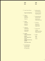
D28
D28NI0006
( blow )
Luceplan Spa
Via E.T. Moneta 40
20161 Milano
Italia
T +39 02662421
F +39 0266203400
[email protected]
www.luceplan.com
manuale installatore
installer’s manual
installationsanleitung
manuel installateur
design
ferdi giardini
INDICE
INDEX
02
Dimensions / Dimensions / Dimensions
INHALT
INDEX
10
Impostazione accensione luce
Setting of the light switching on
Anordnung des Lichteinschaltens
Configuration allumage lumière
12
Impostazione segnalatore acustico
Setting of the acoustic signaller
Anordnung des Tonsignals
Configuration signalisation acoustique
13
Sostituzione fusibile
Replacement of the fuse
Austausch der Sicherung
Remplacement du fusible
14
Problemi comuni e soluzioni
Troubleshooting
Allgemeine Probleme und Auflösungen
Problèmes communs et solutions
18
ATTENZIONE
WARNING
ACHTUNG
ATTENTION
Montaggio / Assembly / Montage / Montage
03
Montaggio corpo
Mounting the body
Montage des Körpers
Montage du corps
06
Montaggio pale
Mounting the blades
Montage der Rügel
Montage des pales
07
Montaggio paralume
Mounting thelampshade
Montage der Lampshade
Montage des Abat-jour
08
Modello D28HD:
impostazioni e sostituzione del fusibile
Modell D28HD:
regulation and replacement of the fuse
Modell D28HD:
einstellungen und austausch der sicherung
Modèle D28HD:
reglage et remplacement du fusible
09
Accesso alla scheda elettronica
Access to the electronic board
Zugang zur Elektronikplatine
Accès a la fiche électronique
01
Montaggio corpo
Mounting the body
Montage des Körpers
Montage du corps
40 cm
Dimensioni
Dimensions
Abmessungen
Dimensions
ø 140 cm
Montaggio
Assembly
Montage
Montage
P2
L N
P1
3X
I
m
P2
P1
D28HD
26 W FSM
GX24d-3
Min 60 W
Max 150 W
HSGST E27
NO
Min 60 W
Max 150 W
IAA E27
g
vv
L’apparecchio non deve essere installato se non vi è una
distanza minima tra il piano di calpestio e la sua parte
inferiore di 2,3 mt. La vicinanza con una lampada
fluorescente potrebbe disturbare il sensore IR del
telecomando.
Das Gerät darf nicht installiert werden,wenn eine Höhe
von mindestens 2,3 Metern zwischen der betretbaren
Fläche und dem untersten Teil des Ventilators nicht
erreicht wird.
Die Nähe zu einer Leuchtstofflampe könnte mit dem
IR-Sensor von dem Fernbedienung stören.
The ventilator must not be installed unless the distance
between the ground and the lower part of the appliance
is 2,3 metres. The proximity to a fluorescent lamp could
interfere with the IR sensor of the remote control.
L’appareil ne doit pas être installé si il n’ya pas une
hauteur minimum de 2,3 mètres du plancher au point le
plus bas du ventilateur. La proximité avec une lampe à
fluorescence pourrait perturber le capteur à infrarouges
du récepteur.
02
f
P2 P1 C L N
MIN 230 cm
D28F
ø 8mm
g
l
fig.1
03
•Verificare che attorno alla posizione di installazione vi sia
lo spazio per consentire la libera rotazione delle pale.
Fissare a soffitto la flangia (f) di sostegno con i 3 tasselli in
dotazione. Utilizzare tasselli idonei al tipo di soffitto.
Aver cura di orientare il ventilatore con i led di
funzionamento (l) in posizione raggiungibile dal raggio
infrarosso emesso dal telecomando (accessorio D28/t).
•Collegare la rete di alimentazione al morsetto (m) posto
sulla flangia seguendo lo schema riportato in figura.
IMPORTANTE:
Non collegare la linea elettrica ai morsetti dedicati ai
pulsanti di comando (P1, P2 e C).
Il collegamento della rete elettrica a questi morsetti
danneggia l’apparecchio.
•Appendere il corpo motore al gancio (g), posto sulla
flangia, come mostrato in fig. 1.
•Connettere il morsetto maschio del motore a quello
femmina (m) della flangia .
•Fissare il corpo dopo averlo ruotato come indicato in
fig. 1 e fissarlo con la vite di chiusura (v).
ATTENZIONE: Agendo sull'interruttore bipolare si
accende un led rosso sull'apparecchio che ne indica la
messa in tensione.
In caso di black-out, al ripristino della corrente elettrica
la lampada si accenderà. Per modificare questa
impostazione vedere pag. 10 (solo modello D28 HD).
Non collegare Blow a valle di regolatori elettronici (es.
dimmer o variatori di velocità). L’utilizzo di questi
dispositivi danneggia l’apparecchio.
04
•Verify that there is sufficient room around the
installation area to allow the free rotation of the blades.
Secure the support flange (f) to the ceiling using
the three screw anchors provided. Use the dowels
suitable for the type of ceiling. Take care to point the
ventilator keeping the operation LEDs (l) in a
visible position to reach the infrared beam emitted
from the remote (accessories D28/t).
•Connect the power supply net to the plug-in clamp (m)
on the flange following the scheme shown in the
picture.
IMPORTANT:
Do not connect the electric line to the clamp
dedicated to the control push buttons (P1, P2 and C).
The connection of the electric line to these clamps
damages the fixture.
•Hang the motor body to the hook (g) on the
flange, as shown in picture 1.
•Connect the male clamp of the motor to the
female one (m) of the flange.
•Fix the body after rotating it as in picture 1 and
secure it with lock up screw (v).
ATTENTION: By acting on the bipolar switch a red
LED lights up on the appliance indicating that it is
energized.
In case of black-out, the lamp will switch on when
the electricity is restored. To modify this
regulation, see page 10 (Only model D28 HD).
•Nachprüfen daß ausreichendes Raum um den
Einbaubereich anwesend ist, um die freie Drehung der
Blätter zu ermöglichen. Die Halteflansch (f) mit den drei
gelieferten Dübeln an der Decke befestigen. Für das
entsprechenden Deckentyp geeignete Dübel anwenden.
Den Ventilator so ausrichten, daß die Funktionsanzeigen
(l) in sichtbarer Position sind bei der Infrarot-Strahl
emittiert von der Fernsteuerung (Zubehör D28/t).
•Das Stromnetz mit der Klemme (m) auf der Flansch
verbinden, dabei das Schema in der Abbildung beachten.
•Den Motor an dem Haken (g) befestigen, der sich an der
Flansch befindet, wie in Abb. 1 gezeigt.
•Die männliche Klemme des Motors mit der weiblichen (m)
der Flansch verbinden.
WICHTIG:
Die Phase nicht an die Klemmen für die Steuertasten
anschließen (P1, P2 und C).
Der Anschluss der Phase an diese Klemmen beschädigt
das Gerät.
•Den Körper nach einer Drehungen, wie in Abb.1 gezeigt,
schließen und ihn mit der Verschlußschraube (v)
befestigen.
ACHTUNG: Durch Betätigen des zwei poliger Schalters
leuchtet die rote Kontrollanzeige auf dem Gerät auf, die
anzeigt, daß es unter Spannung steht.
Im Falle eines Stromausfalls schaltet sich die Leuchte
automatisch ein, wenn das Stromnetz wiederhergestellt
ist. Um diese Einstellung zuändern, siehe Seite 10 (Nur
Modell D28HD).
•Vérifiez la disponibilité de l’espace suffisant à permettre
la libre rotation des palettes tout autour à la position
d’installation.
Fixer la bride (f) de soutien au plafond à l’aidedes 3
chevilles fournies. Utilisez des chevilles aptes au type de
plafond intéressé par l’installation. Orienter le ventilateur
avec les diodes defonctionnement (l) en position visible
par le faisceau infrarouge émis par la télécommande
(accessoire D28/t).
•Brancher la borne (m) placée sur la bride ausecteur en
suivant le schéma reporté dans la figure.
•Suspendre le corps moteur au crochet (g) placésur la
bride, comme le montre la fig. 1.
•Connecter la borne mâle du moteur à la borne femelle
(m) de la bride.
IMPORTANT: Ne pas connecter la ligne électrique sur les
bornes de commande (P1,P2 et C).
La connexion du réseau électrique à ces bornes
endommage l’appareil.
•Fixer le corps après une rotation comme dans la fig. 1 et
le fixer à l’aide de la vis (v) de fermeture.
ATTENTION: Quand on actionne l’interrupteur bipolaire,
un diode rouge s’allume sur l’appareil pour indiquer qu’il
a été mis sous tension.
En cas de coupure d’électricité, la lampe s’allumera de
nouveau à la réinsertion du courant électrique. Pour
modifier cette position voire page 10 (Uniquement
modèle D28 HD).
Do not connect Blow to electronic regulators (for
example dimmer or speed regulators).
The use of these devices damages the fixture.
Blow nicht an elektronische Steuerungen
anschließen (z.B. Dimmer oder Geschwindigkeitsregler).
Der Einsatz dieser Komponenten beschädigt das Gerät.
Ne pas connecter Blow avant les régulateur
sélectroniques (ex. dimmer ou variateurs devitesse).
L’utilisation de ces dispositifs endommage l’appareil.
05
Montaggio pale
Mounting the blades
Montage der Rügel
Montage des pales
1
Montaggio paralume
Mounting the lampshade
Montage der Lampshade
Montage des Abat-jour
a
d1
d2
2
b
Attenzione! Montare le pale con cura e seguendo
attentamente l’orientamento indicato in figura.
1. Assemblare le pale, serrando con cautela le tre viti
corte (a) negli inserti filettati del disco d2, in modo da
non lasciare spazi vuoti tra i dischi e le pale.
2. Fissare le pale al paralume con le tre viti lunghe (b) in
dotazione.
Inserire la lampadina e inserire il paralume (p), sul
motore. Fissarlo con le tre viti (s) in dotazione,
attraverso i fori (o).
Attention! Mount the blades carefully, following the
direction as shown in the picture.
1. Assemble the blades, by fastening the three short
screws (a) in the threaded seats of the disc d2, in order
to avoid empty spaces between the discs and the blades.
2. Secure the blades to the shade with the three long
screws (b) provided.
Das Leuchtmittel einsetzen, den Schirm (p) über
den Motor stülpen und ihn mit den drei beiliegen
den Schrauben (s), die in die Bohrungen (o)
gestecktwerden, fixieren.
Achtung! Die Flügel sorgfältig und unter Beachtung der
in der Abbildung angegebenen Ausrichtung montieren.
1. Die Flügel zusammensetzen, dabei drei kurzen
Schrauben (a) vorsichtig in den Gewindeeinsätzen der
Sheibe d2 festziehen, so dass zwischen Scheibe und
Flügel kein Abstand bleibt.
2. Die Flügel mit den drei langen beiliegenden
Schrauben (b) am Leuchtenschirm befestigen.
Insert the bulb, position the shade (p) on the motor
and fix it with the three provided screws (s) through
the holes (o).
s
o
Enfiler l’ampoule et positionner l’abat-jour (p) sur
le moteur, en le fixant à l’aide des trois vis (s)
fournies, àtravers les trous (o).
p
Attention! Monter les pales avec soin, suivant la
direction indiquée dans la figure.
1. Assembler les pales, en serrant les trois vis courtes
(a) dans les inserts filetés du disque d2 avec précaution,
pour ne pas laisser des espaces vides entre les diques
et les pales.
2. Fixer les pales à l’abat-jour à l’aide des trois vis
longues (b) fournies.
06
07
Accesso alla scheda elettronica
Access to the electronic board
Zugang zur Elektronikplatine
Accès a la fiche électronique
Modello D28HD:
Per accedere alla scheda elettronica, allentare la
vite (v) abbassare il corpo motore, e scollegare il
morsetto di alimentazione dal supporto (f).
Sganciare il corpo motore dal gancio (g).
Svitare le tre viti (h) per rimuovere lo schermo
protettivo (q).
g
impostazioni e sostituzione del fusibile
Modell D28HD:
v
regulation and replacementof the fuse
Modell D28HD:
f
To access the electronic board, unscrew
the screw (v), release the motor body from the
supporting flange (f) and disconnect the connector.
Unhook the motor body from the hook (g).
Unscrew the three screws (h) to remove the
protective screen (q).
1
einstellungen und austauschder sicherung
Modèle D28HD:
h
reglage et remplacement du fusible
Um an die Elektronikplatine zu gelangen, die
Schraube (v) lösen, den Motorkörper aus dem
Halteflansch (f) aushaken und die Klemmeabziehen.
Den Motorkörper aus dem Haken (g) aushaken.
Die drei Schrauben (h) lösen, um den Schutzschild (q)
zu entfernen.
q
v
08
Pour accéder à la fiche électronique dévisser la
vis (v), décrocher le bloc moteur de la bride de
soutien (f) et déconnecter la borne.
Retirer le bloc moteur du crochet (g).
Dévisser les trois vis (h) pour enlever l’écran
de protection (q).
09
Impostazione accensione luce
Setting of the light switching on
Anordnung des Lichteinschaltens
Configuration allumage lumière
SW2
10
Il ventilatore Blow è impostato in modo tale che,
all’atto della messa in tensione del prodotto, la
luce si accenda alla massima intensità.
E’ possibile modificare questa impostazione,
spostando lo Switch SW2 dalla posizione 1 alla
posizione 0. Con questa impostazione all’atto della
messa in tensione dell’apparecchio, la luce resterà
spenta. Per accenderla o regolarla utilizzare i
pulsanti o il telecomando.
Per spostare lo Switch estrarlo e reinserirlo nella
posizione desiderata.
Al termine dell’operazione, riposizionare lo
schermo protettivo e fissarlo con le tre viti
precedentemente rimosse.
Der Ventilator Blow ist so eingestellt, dass sich
beim Anlegen der Spannung das Licht mit
maximaler Stärke ein schaltet. Es ist möglich,
diese Einstellung zu ändern, indem man den
Schalter SW2 von der Position 1 auf die Position 0
verschiebt. Bei dieser Einstellung bleibt das Licht
ausgeschaltet, wenn die Spannung angelegt wird.
Um es anzuschalten oder zu regulieren, die
Wandschalter oder die Fernbedienung benutzen.
Zum Verschieben den Schalter herausziehen und
ihn in der gewünschten Position wieder
einstecken. Am Ende dieses Vorgangs den
Schutzschirm wieder aufsetzen und ihn mit den
drei zu vor entfernten Schrauben befestigen.
The ventilator Blow is set up so that, when the
product is powered, the light switches on at the
maximum intensity. It is possible to change this
regulation by moving the Switch SW2 from position
1 to position 0.
With this regulation, when the appliance is powered,
the light remains switched off.
To switch the light on and regulate it, use the push
buttons or the remote control. To move the Switch,
pull it out and reinsert it in the wished position.
At the end of this operation, reposition the
protective screen and fix it with the three
previously removed screws.
Le ventilateur Blow est réglé de façon que,
lorsque le produit est mis en tension, la lumière
s’allume à son intensité majeure.
Il est possible de modifier ce réglage, en
déplaçant le Switch SW2 de la position 1 à la
position 0. Avec ce réglage, quand l’appareil est
mis en tension la lumière reste éteinte.
Pour l’allumer ou la régler utiliser les poussoirs
ou la télécommande.
Pour déplacer le Switch il faut l’extraire et le
réinsérer dans la position désirée.
A la fin de cette opération,repositionner l’écran de
protection et le fixer avec les trois vis
précédemment enlevées.
11
Impostazione segnalatore acustico
Setting of the acoustic signaller
Anordnung des Tonsignals
Configuration signalisation acoustique
Sostituzione fusibile
Replacement of the fuse
Austausch der Sicherung
Remplacement du fusible
Il ventilatore Blow è impostato in modo tale che,
all’arresto delle pale emetta una segnalazione
acustica (beep). E’ possibile eliminare la
segnalazione acustica spostando lo Switch SW3
dalla posizione 1 alla posizione 0. Per spostare lo
Switch estrarlo e reinserirlo nella posizione
desiderata. Riposizionare lo schermo protettivo e
fissarlo con le tre viti precedentemente rimosse.
Il regolatore di luminosità (dimmer) è protetto
mediante fusibile del tipo 5X20 F 1,0A H.
In caso di guasto dello stesso, sostituirlo con quello di
riserva in dotazione (z) o con uno dello stesso tipo.
Riposizionare lo schermo protettivo e fissarlo con
le tre viti precedentemente rimosse.
z
The dimmer is protected by a fuse type 5X20 F 1,0AH.
If the fuse is damaged, replace it with the spare
one supplied (z) or with one of the same type.
Reposition the protective screen and fix it with the
three previously removed screws.
The ventilator Blow is set up so that, when the
blades stop, an acoustic beep is uttered. It is
possible to avoid this signal by moving the Switch
SW3 from position 1 to position 0. To move the
Switch, pull it out and reinsert it in the wished
position. At the end of this operation, reposition the
protective screen and fix it with the three
previously removed screws.
SW3
Der Ventilator Blow ist so eingestellt, dass beim
Anhalten der Flügel ein Tonsignal (beep) ertönt.
Es ist möglich, dieses Signal aus zuschalten,
indem man den Schalter SW3 von der Position 1
auf die Position 0 verschiebt. Zum Verschieben den
Schalter herausziehen und ihn in der gewünschten
Position wieder einstecken. Den Schutzschirm
wieder aufsetzen und ihn mit den drei zu vor
entfernten Schrauben befestigen.
Der Lichtstärkeregler (Dimmer) wird von einer
Sicherung des Typs 5X20 F 1,0A H geschützt.
Im Falle eines Defekts derselben ist sie durch die
mitgelieferte Reservesicherung (z) desselben Typs zu
ersetzen.
Den Schutzschirm wieder aufsetzen und ihn mit den
drei zuvor entfernten Schrauben befestigen.
5 X 20 F 1,0A H
Le régulateur de luminosité (dimmer) est protégéà
travers un fusible du type 5X20 F 1,0A H.
Si ce fusible est défectueux, le substituer avec
celui donné en réserve (z) ou avec un du même type.
Repositionner l’écran de protection et le fixer avec
les trois vis précédemment enlevées.
Le ventilateur Blow est réglé de façon que, quand
les pales s’arrêtent, il émet une signalisation
acoustique (beep). Il est possible d’enlever cette
signalisation déplaçant le Switch SW3 de la
position 1 à la position 0. Pour déplacer le Switch il
faut l’extraire et le réinsérer dans la position
désirée. Repositionner l’écran de protection et le
fixer avec les trois vis précédemment enlevées.
12
13
Problemi comuni e soluzioni
Troubleshooting
Di seguito è riportato un elenco delle più comuni anomalie del ventilatore luminoso; qualora si
verificassero anomalie tecniche non presenti in elenco e in caso di mancata risoluzione del problema,
rivolgersi al servizio assistenza autorizzato di zona.
In the following, you find a list of the most common anomalies of the bright fan; in case of technical
problems, not present in the over mentioned list, and in case of impossible solution of the problem, refer
to the local customer assistance service.
problema
la luce non si accende
possibili cause
cosa fare
- sostituire la lampadina
- la lampadina bruciando crea un picco di
corrente che potrebbe danneggiare il fusibile - sostituire il fusibile utilizzando quello in dotazione presente
in prossimità della scheda elettronica o con un fusibile di
uguali caratteristiche
il varialuce non funziona - fusibile interrotto
(solo D28HD)
il prodotto non risponde ai - a monte dell'impianto potrebbe essere
installato un varialuce
comandi
- sostituire Il fusibile utilizzando quello in dotazione presente
in prossimità della scheda elettronica o con un fusibile di
uguali caratteristiche
-scollegare il varialuce e collegare direttamente l'interruttore
bipolare da prevedere a monte del prodotto
- sostituire la batteria del telecomando
il prodotto non funziona se - batteria esaurita
comandato mediante - errato orientamento del ricevitore situato sul - posizionare il trasmettitore difronte al ricevitore evitando
prodotto in prossimità dei LED di segnalazione qualsiasi ostacolo tra i due elementi
telecomando
il cicalino non funziona
- settaggio errato della scheda elettronica
- vedere pag. 12 l'impostazione del segnale acustico
la luce non si accende - sorgente luminosa errata. Il prodotto D28HD - vedere pag. 10 l'impostazione accensione luce
alimentando il prodotto NON accetta lampade fluorescenti compatte
il prodotto oscilla
eccessivamente
- errato allineamento dei fissaggi del prodotto - smontare il paralume completo di pale e collegarlo ruotato
di 120°
problem
possible causes
what to do
lamp does not switches on - the bulb, when it burns out, generates a
current peak, that could damage the fuse
- replace the bulb
- replace the fuse by using the supplied one present near the
printed circuit board or with a fuse having the same
characteristics
the light variator does not - interrupted fuse
work (only model D28HD)
- replace the fuse by using the supplied one present near the
printed circuit board or with a fuse having the same
characteristics
the appliance does not
work according to the
commands
- upstream the system a light variator could
be installed
- disconnect the light variator and connect directly the bipolar
switch, which is to be installed upstream the appliance
- replace the remote control battery
the appliance does not - exhausted battery
work if it is operated by the - wrong orientation of the receiver positioned - position the transmitter in front of the receiver by avoiding
on the appliance near the signaling LED
any obstacle between the two elements
remote control
the buzzer does not work - wrong setting of the printed circuit board
- see page 12, setting of acoustical signal
the lamp does not switch - wrong luminous source. The appliance does - see page 10, setting of light switching on
on when the device is NOT accept compact fluorescent lamps
electrically fed
the appliance excessively - wrong alignment of the appliance clampings - disassembly the shade together with blades and connect it
120° turned
oscillates
la luce non si accende o - sorgente luminosa errata. Il prodotto D28HD - eliminare la sorgente luminosa fluorescente compatta
NON accetta lampade fluorescenti compatte
sfarfalla.
the lamp does not switch - wrong luminous source. The appliance D28HD - eliminate the compact luminous fluorescent source
does NOT accept compact fluorescent lamps
on or it is flickering
la lampada fluorescente - le lampadine fluorescenti a fine vita
- sostituire la lampadina
sfarfalla ed le pale si innescano dei treni d'onda luminosi che
accendono
possono interferire con le funzioni del prodotto
inavvertitamente
the fluorescent lamp is - the fluorescent lamps, at end-of-life, start
flickering and the blades luminous wave trains that can interfere with
unintentionally switch on the appliance functions
la lampada fluorescente - le lampadine fluorescenti quando si
sfarfalla
esauriscono inizziano a sfarfallare
- sostituire la lampadina prima che smetta di funzionare per
evitare danni al gruppo di alimentazione
il prodotto non funziona in - collegamento ERRATO della rete ai terminali - vedere pag. 03
fase di installazione
di comando previsti per la bassa tensione
14
- replace the bulb
the fluorescent lamp is - when the fluorescent lamps are exhausting, - replace the bulb before it stops working to avoid damages to
they start flickering
the feeding unit
flickering
- see page 03
the appliance does not - WRONG connection of the mains to the
work during the installation control terminals foreseen for the low voltage
15
Allgemeine Probleme und Auflösungen
Problèmes communs et solutions
Im folgendem finden Sie eine Liste der üblichsten Anomalien des Lichtlüfters; im Fall von technischen
Problemen, die nicht in der Liste genannt werden, und im Fall von unmöglichen Lösungen des Problems,
beziehen Sie sich auf den örtlichen Kunden-Dienst.
Ci de suite, une liste des anomalies les plus fréquentes du ventilateur/lampe; lors de la survenance
d’anomalies techniques n’étant pas présentes dans la dite liste, et au cas d’impossibilité de solution du
problème, adressez-vous au service après vente autorisé de votre zone.
probleme
mögliche ursachen
was zu machen
die Lampe schaltet nicht ein - wenn sie brennt durch, generiert die
- austausch von Glühbirne
Glühbirne eine Stromspitze, die die Sicherung - austausch der Sicherung. Die mitgelieferte Sicherung
beschädigen könnte
anwenden, die bei der Printplatte anwesend ist oder eine
Sicherung mit identischen Eigenschaften anwenden
- unterbrochene Sicherung
die Lampenregler
funktioniert nicht
(nur Ausführung D28HD)
das Gerät funktioniert nicht - stromaufwärts des Systems, könnte der
Lampenregler installiert werden
nach den Befehlen
- austausch der Sicherung. Die mitgelieferte Sicherung
anwenden, die bei der Printplatte anwesend ist oder eine
Sicherung mit identischen Eigenschaften anwenden
- den Lichtregler abtrennen und unmittelbar den zweipoligen
Schalter verbinden, der stromaufwärts des Gerätes installiert
werden muss
problème
causes probables
la lampe ne s’allume pas - lorsqu’elle grille, l’ampoule crée une crête
de courant qui pourrait endommager le
fusible
le variateur d’intensité - interruption du fusible
d’éclairage ne fonctionne pas
(uniquementpourmodèleD28HD)
que faire
- remplacez l’ampoule
- remplacez le fusible par celui qui est fourni en complet, se
trouvant près de la carte électronique, ou bien par un autre
ayant des caractéristiques identiques
- remplacez le fusible par celui qui est fourni en complet, se
trouvant près de la carte électronique, ou bien par un autre
ayant des caractéristiques identiques
le produit ne répond pas - il se peut que, en amont de l’installation, il y - déconnectez le variateur d’éclairage et connectez directement
aux commandes
ait un variateur d’intensité d’éclairage
l’interrupteur bipolaire à envisager en amont du produit
das Gerät funktioniert nicht,- Verbrauchte Batterie
- austausch von Batterie-Fernbedienung
- falsche Orientierung des auf dem Gerät bei - den Transmitter vor dem Empfänger aufstellen, und alle
wenn es von
Fernbedienung betätigt ist dem Signal-LED positionierten Empfängers Behinderungen zwischen den zwei Elementen verhindern
le produit ne fonctionne pas- batterie à plat
- remplacez la batterie de la commande à distance
si actionné par la
- orientation non correcte du récepteur sur le - positionnez le transmetteur en face du récepteur, en évitant
commande à distance produit à proximité des diodes LEDdesignalisation d'interposer tout obstacle que ce soit entre les deux éléments
der Summer funktioniert nicht - falsche Einstellung der Printplatte
le buzzer ne fonctionne pas - mise au point non correcte de la carte électronique - voir page 12: mise au point de la signalisation acoustique
- siehe Seite 12, Einstellung von akustischem Signal
die Lampe schaltet nicht - falsche Lichtquelle. Das Gerät D28HD
- siehe Seite 10, Einstellung von Lichteinschaltung
ein, wenn das Gerät
akzeptiert NICHT kompakte Leuchtstofflampen
stromgespeist ist
das Gerät schwingt
übermäßig
- falsche Ausrichtung der Gerätsbefestigungen
- ausbau des Schirmes zusammen mit den Blättern und es 120° gedreht - verbinden
- die kompakte Leuchtstoffquelle beseitigen
die Lampe schaltet nicht - falsche Lichtquelle. Das Gerät D28HD
ein oder sie ist flackernd akzeptiert NICHT kompakte Leuchtstofflampen
- austausch von Glühbirne
die Leuchtstofflampe ist - die Leuchtstofflampen, bei Laufzeitende,
flackernd und die Blätter starten Lichtwellenzüge, die die Gerätfunktionen
schalten unfreiwillig ein stören können
die Leuchtstofflampe ist - wenn die Leuchtstofflampen verbraucht
sind, starten sie, zu flackern
flackernd
während des Aufbau - FALSCHE Netzwerk-Verbindung zu den
funktioniert das Gerät nicht Bedienanschlüssen, die für niedrige
Spannung vorgesehen sind
16
- austausch der Glühbirne, bevor sie funktioniert nicht mehr,
um Beschädigungen der Speisungseinheit zu verhindern
- siehe Seite 03
la lampe ne s’allume pas - source d’éclairage non correcte. Le produit D28HD - voir page 10: mise au point de l’allumage de la lampe
même lorsque l'appareil N’ACCEPTE PAS l’installation de lampes à
est mis sous tension fluorescence compactes
l'appareil oscille de
manière excessive
- alignement non correct des fixages du produit - démontez l'abat-jour complet de ses palettes et
connectez-le après l’avoir tourné de 120°
la lampe ne s’allume pas - source d’éclairage non correcte. Le produit - éliminez la source d’éclairage à fluorescence compacte
D28HD N’ACCEPTE PAS l’installation de
ou présente un effet
lampes à fluorescence compactes
papillotement
la lampe à fluorescence a - a' la fin de leur durée de vie, les lampes à
- remplacez l’ampoule
un effet papillotement et les
palettes se mettent en fluorescence donnent lieu à des trains d’onde
fonction de manière non lumineux pouvant interférer avec les fonctions
souhaitée
du produit
la lampe à fluorescence a - lorsqu’elles sont en train de s’épuiser, les
un effet papillotement lampes à fluorescence provoquent un
papillotement
- remplacez l’ampoule avant que celle-ci cesse de fonctionner, de
manière à éviter tout dommage au groupe d’alimentation
le produit ne fonctionne pas- connexion ERRONEE du réseau aux bornes - voir page 03
à l’étape de l’installation de commande prévues pour la basse tension
17
WARNING
ATTENZIONE
LA SICUREZZA DELL'APPARECCHIO E' GARANTITA SOLO
RISPETTANDO QUESTE ISTRUZIONI, SIA IN FASE DI
INSTALLAZIONE CHE DI IMPIEGO; E' NECESSARIO
CONSERVARLE. IL PRODUTTORE NON RISPONDE DI DANNI
DERIVANTI DA UN USO SCORRETTO DELL'APPARECCHIO.
Dopo aver tolto l'imballaggio, assicurarsi dell'integrità
dell'apparecchio. Gli elementi dell'imballaggio (sacchetti in
plastica, polistirolo espanso, graffette) non devono essere
lasciati alla portata dei bambini, in quanto potenziali fonti di
pericolo. Non utilizzare l'apparecchio se danneggiato.
Questo apparecchio dovrà essere destinato solo all'uso per il quale è
stato espressamente concepito e cioè per agitare l'aria ed illuminare.
Non sono ammesse altre installazioni diverse da quella a soffitto.
Il costruttore non può essere considerato responsabile di
eventuali danni derivati da usi impropri, erronei e irragionevoli.
Prima di collegare l'apparecchio accertarsi che i dati di targa
siano rispondenti a quelli della rete di distribuzione (la targa è
situata nella parte superiore del motore). In caso di guasto e/o
cattivo funzionamento dell'apparecchio spegnerlo e non
manometterlo.
Per l'eventuale riparazione rivolgersi solamente a personale
specializzato.
INSTALLAZIONE
L'installazione deve essere effettuata secondo le istruzioni
Luceplan da personale professionalmente qualificato.
Un'errata installazione può causare danni a persone, animali o
cose nei confronti dei quali il costruttore non può essere
considerato responsabile. La sicurezza elettrica di questo
apparecchio è assicurata soltanto quando lo stesso è
correttamente collegato ad un efficace impianto di messa a
terra come previsto dalle vigenti norme di sicurezza elettrica.
All'atto dell'installazione e ogni qual volta si intervenga
sull'apparecchio, assicurarsi che sia stata tolta la tensione di
alimentazione!
18
NOTA PER L’IMPIANTO
Per normativa, il punto di alimentazione deve essere
comandato da un interruttore bipolare idoneo ai dati elettrici
dell’apparecchio. Se si desidera il controllo di BLOW anche da
parete, prevedere, a fianco dell’interruttore, due pulsanti
(normalmente aperti).
ATTENZIONE
L’apparecchio non deve essere installato se non vi è una
distanza minima tra il piano di calpestio e la sua parte inferiore
di 2,3 mt. Mantenere un’ adeguata distanza da pareti e oggetti.
Non lasciare l’apparecchio inutilmente inserito.
Spegnere l’interruttore di alimentazione quando l’apparecchio
non è utilizzato.
Prodotto installabile solo su superfici orizzontali ed in ambienti
interni.
Se dopo aver letto queste istruzioni rimangono dei dubbi
contattare il rivenditore prima di montare l'apparecchio.
THE SAFETY OF THE APPLIANCE IS GUARANTEED ONLY IF
THESE INSTRUCTIONS ARE FULLY RESPECTED, BOTH
DURING INSTALLATION AND USE; THEREFORE KEEP THEM
IN A SAFE PLACE. THE MANUFACTURER CANNOT BE HELD
RESPONSIBLE FOR ANY MATERIAL OR PHYSICAL DAMAGE
DERIVING FROM IMPROPER USE OF THE APPLIANCE.
After unpacking the appliance, be sure it has not been
damaged. The packing components (plastic bags, expanded
polystyrene, paper clips) must be kept out of reach of children,
as they are potentially dangerous.
Do not use the appliance if damaged.
This appliance must be intended to be used only for what is has
been designed, that is to move the air and to illuminate.
No other installations different from ceiling mounting are allowed.
The manufacturer is not liable for eventual damage due to
misuse, incorrect or inadequate use. Before connecting the
appliance, be sure the voltage rate correspond to those of the
distribution network (the plaque is on the upper part of the
motor). In case of fault or malfunctioning switch the appliance
off and do not tamper with it. For repairing apply only to
qualified personnel.
INSTALLATION NOTE
According to the standard, the power supply must be controlled
by a bipolar switch, suitable for electrical data to the appliance.
If BLOW should be controlled by a switch on the wall, it is
recommended to mount two push buttons next to the switch
(normally opened).
ATTENTION
The ventilator must not be installed unless the distance
between the ground and the lower part of the appliance is 2,3
metres.
Keep an adequate distance from walls, objects.
Do not leave the appliance uselessy switched on.
Switch the power supply off when the appliance is not used.
Appliance to be installed on horizontal surfaces and internal
rooms.
If after reading these instructions there is any doubt, contact
the retailer before assembling the appliance.
INSTALLATION
Installation has to be done following Luceplan's instruction by
qualified personnel. An erroneous installation can cause
damages to people, animals and objects for which the
manufacturer cannot be held responsible.The electrical safety
is granted only when the appliance is correctly connected to an
effective ground system, as provided by the electrical safety
regulation.
Upon installation and any intervention on the appliance, check
the power supply voltage is off!
19
ACHTUNG
DIE GERÄTESICHERHEIT IST NUR DANN GEWÄHRLEISTET, WENN
SIE DIESE INSTALLATIONS- UND BEDIENUNGSANLEITUNG
BERÜCKSICHTIGEN; BEWAHREN SIE DIE ANLEITUNG AUF.
DER HERSTELLER ÜBERNIMMT KEINE HAFTUNG BEI
UNSACHGEMÄSSER VERWENDUNG DES GERÄTS.
Überprüfen Sie nach dem Auspacken, ob das Gerät
unbeschädigt ist. Die Verpackung (Plastiktüten, Schaumstoff,
Klammern) dürfen nicht in Kinderhände geraten, da sie
mögliche Gefahrenquellen darstellen.
Das Gerät nicht verwenden, wenn es beschädigt ist,d.h. um die
Luft zu bewegen und zu beleuchten. Installationen verschieden
von Deckenmontage-Typ sind nicht erlaubt. Dieses Gerät darf
nur für den vorgesehenen Einsatzzweck verwendet werden.
Der Hersteller haftet nicht bei Schäden, die auf
unsachgemäßen, falschen oder unvernünftigen Gebrauch
zurückzuführen sind. Vergleichen Sie die Daten auf dem
Typenschild mit dem vorhandenen Stromnetz, bevor Sie das
Gerät anschließen (auf der Oberseite des Motors).
Im Fall eines Fehlers oder schlechten Funktionierens des
Gerätes, dieses abschalten und nicht öffnen.
Für die eventuelle Reparatur nur professionell qualifiziertes
Personal aufsuchen.
INSTALLATION
Die Installation muß gemäß den Anweisungen der Luceplan
erfolgen. Eine falsche Installation kann Verletzungen von
Personen und Tieren, sowie Beschädigung von Gegenstände
nverursachen, für die der Hersteller keine Verantwortung
tragen kann.
Die elektrische Sicherheit dieses Gerätes ist nur gewährleistet,
wenn dieses richtig mit einer Anlage mit Erdung verbunden ist,
wie es in der aktuellen Gesetzgebung vorgesehen ist.
Stellen Sie sicher, dass die Stromverbindung unterbrochen ist,
bevor das Gerät installiert oder gewartet wird!
20
ATTENTION
MONTAGEANLEITUNG
Nach den Vorschriften, muss die elektrische Versorgung von
einem zweipoligen Schalter gesteuert werden, der geeignet für
die elektrische Daten des Gerätes ist. .
Wenn eine Wandsteuerung von BLOW gewünscht wird, sollten
zwei Knöpfe neben dem Schalter montiert werden
(normalerweise offen).
ACHTUNG
Das Gerät darf nicht installiert werden,wenn eine Höhe von
mindestens 2,3 Metern zwischen der betretbaren Fläche
und dem untersten Teil des Ventilators nicht erreicht wird.
Den entsprechenden Abstand zu Wänden und Gegenständen halten.
Das Gerät nicht unnütz eingeschaltet halten. Den Netzschalter
ausschalten, wenn das Gerät nicht benutzt wird.
Auf liegenden Oberflächen und inneren Räumen installierbares
Gerät.
Falls Sie nach der Lektüre dieser Anleitung weitere Fragen
haben sollten, wenden Sie sich bitte an den Händler, bevor Sie
das Gerät montieren.
LA SÉCURITÉ DE L’APPAREIL N’EST GARANTIE QUE SI
CES INSTRUCTIONS SONT RESPECTÉES, AUSSI BIEN
LORS DE L’INSTALLATION QUE DE L’UTILISATION; IL
FAUT DONC LES CONSERVER. LE FABRICANT NE
RÉPOND PAS DE DOMMAGES DÉRIVÉS D’UNE
UTILISATION INCORRECTE DE L'APPAREIL.
Après avoir déballé l’appareil, s’assurer de son intégrité.
Les éléments d'emballage (sacs en plastique, polystyrène
expansé, agrafes) ne doivent pas être laissés à la portée des
enfants, puisqu’ils constituent de sources potentielles de
danger. Ne pas utiliser l’appareil s’il est endommagé.
Cet appareil ne devra être destiné qu’à l’utilisation pour laquelle il
a été expressément conçuc’est-à-dire brasser l’air et éclairer.
N'est admise aucune installation autre que celle au plafond.
Le fabricant ne peut pas être tenu responsable de dommages
éventuels dérivés d’utilisations impropres, incorrectes ou
insensées. Avant de brancher l’appareil, s’assurer que les
données de la plaque signalétique correspondent à celles du
secteur (la plaque se trouve sur le haut du moteur).
En cas de panne et/ou de mauvais fonctionnement de
l’appareil, veuillez l’éteindre et ne pas le trafiquer. Pour la
réparation, s’adresser uniquement à du personnel specialisé.
NOTE POUR L’INSTALLATION
Selon la réglementaiton, l’alimentation doit être commandée
par un interrupteur bipolaire apte aux caractéristiques
électriques de l’appareil. Dans le cas où on souhaiterait
commander le BLOW par un interrupteur à parois, il faut
envisager, près de l’interrupteur, deux boutons-poussoirs
(normalement ouverts).
ATTENTION
L’appareil ne doit pas être installé si il n’ya pas une hauteur
minimum de 2,3 mètres du plancher au point le plus bas du
ventilateur.
Maintenir une distance appropriée des murs, des objets.
Ne pas laisser l’appareil branché inutilement. Couper
l’interrupteur d’alimentation quand on n’utilise pas l’appareil.
Produit à installer uniquement sur des surfaces horizontales et
à l’intérieur.
Si après avoir lu ces instructions il en reste des doutes,
contacter le revendeur avant de monterl’appareil.
INSTALLATION
L’installation doit être effectuée selon les instructions de
Luceplan et par du personnel professionnellement qualifié.
Une installation erronée pourrait provoquer des dommagesà
des personnes, des animaux ou des choses, vis-à-vis desquels
le constructeur ne peut pas être considéré responsable. La
sécurité électrique de cet appareil n’est assurée que quand
celui-ci a été correctement branché à une installation de mise
à la terre efficace, comme prévu par les normes de sécurité
électrique en vigueur. Lors de l’installation et à chaque
intervention sur l’appareil, s’assurer que la tension
d’alimentation a été coupé!
21