1
Ditec Energy
0DT828
rev. 2014-06-13
Handbuch die montage, wartung, bedienung.
DE
Installation manual, maintenance, use.
EN
(Original Anleitung)
(Original instructions)
www.ditecentrematic.com
INHALTSVERZEICHNIS
Kap.Inhalt ...........................................................................................................................................S.
1. ALLGEMEINE SICHERHEITSHINWEISE ................................................................................... 2
2. TECHNISCH MERKMALE ........................................................................................................... 3
3. MECHANISCHE INSTALLATION
3.1 Anfängliche Überprüfungen..................................................................................................... 4
3.2 Befestigung der Seitenpfosten................................................................................................. 4
3.3 Montage des Querbalkens ...................................................................................................... 4
3.4 Vorbereitung des Querbalkens ............................................................................................... 4
3.5 Montage des Torbehangs........................................................................................................ 4
3.6 Montage des Getriebemotors ................................................................................................. 4
3.7 Einbau der Lichtschranken...................................................................................................... 4
3.8 Einbau der Kontaktleiste.......................................................................................................... 4
4. ELEKTRISCHE ANSCHLÜSSE
4.1 Elektrischer Schaltschrank....................................................................................................... 5
4.2 Anschlüsse Schaltkasten / Motor / Schutzvorrichtungen......................................................... 5
4.3 Sicherheits-Lichtschranken...................................................................................................... 5
5. ELEKTRONISCHE SCHALTTAFEL
5.1 49E - K22 anschlüsse.............................................................................................................. 6
5.1 49E - K26 anschlüsse............................................................................................................ 10
5.2 47E (inverter) - anschlüsse.................................................................................................... 12
6. einstellungen UND START
6.1 Überprüfung der Bewegungsrichtung ................................................................................... 16
6.2 Einstellung der verdrahteten Kontaktleiste............................................................................ 16
7. STÖRUNGSSUCHE.................................................................................................................... 17
8. WARTUNGSPLAN...................................................................................................................... 18
1. ALLGEMEINE SICHERHEITSHINWEISE
Das vorliegende installationshandbuch ist ausschliesslich für das Fachpersonal bestimmt.
Montage, elektrische Anschlüsse und Regelungen sind auf der Grundlage der bestehenden Vorschriften nache den
Regeln der Technik auszüfuhren. Vor Einbaubeginn sind die Anweisungen sorgfältig durchzulesen. Falcher Einbau
kann Gefahr mit sich bringen Das Verpackungsmaterial (Kunststoff, Polystyrol usw.) ist vorschriftsmäßig zu entsorgen. Es
ist von Kindern fernzuhalten, da es eine Gefahr für si bedeutet.
Vor Beginn der Montage ist der einwandfreie Zustand des Produkts zu überprüfen. In explosionsgefährdeten Bereichen
darf das Produkt nicht eingebaut werden: Entzündbare Gase oder Rauch stellen eine ernsthafte Sicherheitsgefährdung dar.
Um die vorgeschriebenen Sicherheitsabstände zu schaffen und Quetsch- Scher- Einzieh- und sonstige Gefahrbereiche
zu vermeiden bzw. abzutrennen, sind vor Montagebeginn die notwendigen baulichen Veränderungen vorzunehmen. Es ist
sicherzustellen, daß die tregende Struktur die erforderlichen Voraussetzungen an Festigkeit und Stäbilität erfüllt.
Der Hesteller des Antriebs haftet nicht, wenn die Torrahmen oder -pfosten, die für den Antrieb vorgesehen sind, nicht
ordnungsgemäß und fachgerecht erstellen sind; er haftet ebenfalls nicht für Verformungen im Betrieb.
Die Sicherheitseinrichtungen (Photozellen, Lichtschranken, Nothalteinrichtungen usw.) sind nach den Regeln der Technik so
zu installieren, daß die geltenden Vorschriften und Richtlinien eingehalten sowie Einbauort, Betriebsweise des Antriebssystems
und die Kräfte, die das Tor beim Antrieb aufweist, berücksichtigt werden.
Die Sicherheitseinrichtungen dienen dem Schutz vor Quetsch-, Scher-, Einzieh- und sonstigen Gefahrbereichen des Tors
nach Montage des Antriebs. Zur Erkennung der Gefahrenbereichen sind die vorgeschiebenen Hinweisschilder anzubringen.
Bei jeder Anlage sind die technischen Daten des Torantriebs gut sichtbar anzubringen. Vor dem Netzanschluß ist sicherzustellen,
daß die Daten auf dem Typenschild mit denen des Stromversorgungsnetzes übereinstimmen.
Netzsetig ist ein Allpoll-Schalter bzw. -Trennschalter mit Abstand der Kontakte in geöffneter Stellung > oder = 3 mm
vorzusehen. Es ist sicherzustellen, daß der Elektroanlage die erforderlichen FI-Schalter und Überstromschutzschalter
vorgeschaltet sind. Der Torantrieb ist an eine ordnungsgemäße Erdung, die nach den geltenden Sicherheitsvorschriften
ausgeführ ist, anzuschließen. Der Hersteller des Antriebs lehnt jede Verantwortung ab, wenn beim Einbau Teile montiert werden,
die weder den Sicherheitsanforderungen noch einem ordungsgemäßen Betrieb entsprechen oder falls Änderungen jeglicher
Art ohne spezifische Genehmigung des Herstellers durchgeführt werden. Bei Reparatur und Austausch sind ausschließlich
Originalersatzteile Entrematic Group AB zu verwenden. Der Einbaubetrieb ist verpflichtet, dem Benutzer alle notwendigen
Informationen für Automatik-, Hand- und Notbetrieb des Torantriebs zu liefern und ihm die Betriebanleitung auszuhändigen.
Optionszubehör
C
Safety Confort
T
Safety Top
Alle Rechte vorbehalten
Die wiedergegebenen Daten wurden mit höchster Sorgfalt zusammengestellt und überprüft. Es kann jedoch keinerlei
Verantwortung für eventuelle Fehler, Auslassungen oder Näherungen, die technischen oder graphischen Notwendigkeiten
zuzuschreiben sind, übernommen werden.
0DT828 2014-06-13
-2-
DE
9
4
3
1
10
11
2
17
12
7
16
15
13
18
14
5
21
20
19
8
6
Rif.
1
2
3
4
5
6
7
8
9
10
11
Beschreibung
Laufschiene
Getriebemotor K22 / K26
Wickelwelle
Wickeltrommel für Riemen des Gegengewichts
Aluminiumprofil der Kontaktleiste
Gummiprofil der Kontaktleiste
Steckdose der Leiste
Anschlusskabel für die Leiste
Vorrichtung für manuellen Betrieb
Stange für manuellen Betrieb
Rechte Stütze
Rif.
16
17
18
19
20
21
22
23
24
25
Beschreibung
Linke Stütze
Aluminiumprofile für Torbehang
Verstärkungsrohr für Torbehang
Elektronische Steuerung
Lichtschranke LAB4
Heberiemen für Torbehang
Riemenbefestigung für Torbehang
Transparente Sektion
Sektion aus Polyester
Schutzbezug für Kontaktleiste
2. TECHNISCHE MERKMALE
ELEKTRONISCHE SCHALTTAFEL DREIPHASEN (49E)
ELEKTRONISCHE SCHALTTAFEL (INVERTER)
Spannungsversorgung ....................... 400 V, 50/60 Hz
Stromaufnahme ....................................................... 6 A
Zubehörversorgung..........................................24V
Motorleistung.................................................. 0,75 KW
Schutzgrad der elektr. Schalttafel........................ IP 55
Betriebstemperat........................................ - 5 + 50 °C
Spannungsversorgung ....... 230 V einphasig 50/60 Hz
Stromaufnahme ..................................................... 16 A
Zubehörversorgung..........................................24V
Motorleistung.................................................. 0,75 KW
Schutzgrad der elektr. Schalttafel........................ IP 55
Betriebstemperat........................................ - 5 + 50 °C
Den Leiterquerschnitt richtig dimensionieren, dazu die angegebene Stromaufnahme heranziehen und die Länge der
Kabel und deren Verlegung berücksichtigen.
-3-
0DT828 2014-06-13
3. MECHANISCHE INSTALLATION DER STRUKTUR UND DER BAUTEILE
Siehe die entsprechenden Zeichnungen für die mechanische Installation auf Seite 24 - 25 (das mittlere Blatt lässt
sich herausnehmen)
3.1 Anfängliche Überprüfungen (Abb.1)
• Die Abmessungen der Öffnung mit den Tormaßen vergleichen. Prüfen, ob mögliche Hindernisse die Montage behindern.
• Sicherstellen, dass die Auflageflächen vollkommen eben sind. Gegebenenfalls mit geeigneten Passscheiben ausgleichen.
• Die Strukturbeschaffenheit der Wandöffnung überprüfen: die sichere Verankerung mittels Bügel oder Dübel muss
gewährleistet sein. Sollte die Konsistenz ungenügend oder zweifelhaft sein, muss eine entsprechende selbsttragende
Metallstruktur angefertigt werden.
3.2 Befestigung der Seitenpfosten (Abb.2)
• Den gesamten Platzbedarf des Querbalkens (LT) messen und die Position der Seitenpfosten markieren.
• Die Stützen der Pfosten an den gekennzeichneten Stellen mit Dübeln der Größe M8 befestigen (Abb.4).
• Die Seitenpfosten ins Lot bringen und laut Bezug (A) bei Außenbügeln oder laut Bezug (B) bei Befestigung auf der
Innenseite der Stütze befestigen. Dübelgröße M8. Die Diagonalen prüfen.
3.3 Montage des Querbalkens
• Die an den Enden des Querbalkens vormontierten Bolzen M8 entfernen.
• Den Querträger mit entsprechendem Hebezeug heben.
• Den Querbalken auf den Seitenpfosten auflegen, die Befestigungsbolzen wieder einsetzen und festziehen (Abb.3).
• Bei Toren mit PL > 4000 wird empfohlen, den Querbalken in der Mitte zu befestigen (um eine unschöne Verbiegung der
Konstruktion zu vermeiden).
3.4 Vorbereitung des Querbalkens
• Unter Bezugnahme auf die (Abb.5A-5B) das Vorgelegerad des Riemens je nach Position des Torbehangs positionieren.
Die Standardposition wird in (Abb.5A) gezeigt.
• Sollte das Vorgelegerad des Riemens nicht in der Position wie in “5A” gezeigt gehalten werden können, das Rad durch
Ausschrauben des Bolzens M8 entfernen und das Vorgelegerad des Riemens in der gewünschten Position neu montieren.
Nach der Befestigung prüfen, ob sich das Rad frei dreht. Den Vorgang für jede Halterung wiederholen
3.5 Montage des Torbehangs
• Den Torbehang in die Seitenpfosten einsetzen und anheben, dabei prüfen, ob die Riemenringe richtig positioniert sind.
• Mithilfe der beigepackten Bolzen M8 die Verbindungsmuffe des Torbehangs am Querbalken befestigen (Abb.6).
• Den Torbehang vorsichtig ganz herunterlassen. Bei Traffic C mit modularem Torbehang: ggf. die Länge des Torbehangs
regulieren, indem der Behang um das Kupplungsrohr gewickelt wird.
• Die Heberiemen des Torbehangs abrollen. Sicherstellen, dass noch mindestens 2 Umdrehungen auf der Wickeltrommel
bleiben (Abb.5).
• Die Riemen durch die bereits entlang des Torbehangs vorbereiteten Riemenringe ziehen (Abb.7).
• Die Riemenenden mithilfe der am 1. Rohr angebrachten Bügeln befestigen (Abb.7).
• Die Rohre mit den Plastikschalen befestigen, damit sie seitlich nicht verrutschen können (Abb.8) am 1. Rohr sind die Schalen
bereits befestigt.
3.6 Montage des Getriebemotors
Manueller Vorgang, falls vorgesehen, die Vorrichtung entsprechend den Angaben aus (Abb.9) bei Getriebemotor K22
und (Abb.10) bei Getriebemotor K26 einbauen.
Den Sicherheitsmikrokontakt unter Beachtung des entsprechenden Plans anschließen und die Funktionstüchtigkeit überprüfen:
der Mikrokontakt muss die Drehung des Motors bei Verbindung des manuellen Vorgangs hemmen.
• Die Passfeder (d) in die entsprechende Nut (e) an der Wickelwelle (Abb.12) einsetzen.
• Den Getriebemotor auf die Welle setzen.
• Den Getriebemotor mit der passenden Befestigungsvorrichtung am Zylinderkopf (Abb.12) befestigen.
•Die Gruppe Silentblock in den entsprechenden Sitz (f) der Halteplatte einsetzen, dabei die Bauteile wie in (Abb.13)
dargestellt positionieren. (g) Beilagscheibe 13x24 - (h) Silentblock Ø 25 - (i) Beilagscheibe 14x36 - (m) Schraube 12x55
• Den Silentblock mit der Mutter (l) befestigen.
3.7 Einbau der Lichtschranken
• Die Behälter auf Stützen installieren. Für den Einbau und die Anschlüsse die Anleitungen in der Verpackung der
Lichtschranken (Abb.14) verwenden.
3.8 Einbau der Kontaktleiste
• Den Torbehang auf ca. 1 m Höhe positionieren.
• Die Kontaktleiste in die untere Tasche des Torbehangs (Abb.15) einsetzen.
• Die Leiste über die gesamte Länge des Torbehangs gleiten lassen und genau mittig zum Torbehangs ausrichten.
0DT828 2014-06-13
-4-
DE
4. ELEKTRISCHE ANSCHLÜSSE
4.1 Elektrischer Schaltschrank
• Die Kabel mit vorverkabelten Klemmleisten in den Behälter einführen und an die Karten anschließen (Abb.16). Kabel in
den Kabelkanal einführen und auf dem Motor vorgesehene Steckverbinder anschließen (Abb.17).
4.2 Anschlüsse Schaltkasten / Motor / Schutzvorrichtungen
• In Schema 18 werden die gelieferten Verkabelungen und ihre Position im Tor angegeben; jede Verkabelung wird durch
eine eigene Bezeichnung auf einem Aufkleber kenntlich gemacht.
4.3 Sicherheits-Lichtschranken
• Die torseitigen Anschlüsse wie in (Abb.18) angegeben vornehmen.
• Die Anschlüsse im Schaltkasten gemäß den Schaltplänen durchführen
16
17
18
FC
C T
0 1
Schwarz
Blau
Tx2
Tx1
7982
7982
Schwarz
Blau
Orange
Rot
A934E/L
A451L
Rx2
Schwarz
Blau
0 1
0 1
0 1
Rx1
Schwarz
Blau
Orange
Rot
4327
7978
A935G/E
A935L
4328
7979
7825A
M
Den Leiterquerschnitt richtig dimensionieren, dazu die angegebene Stromaufnahme heranziehen und die Länge der
Kabel und deren Verlegung berücksichtigen.
-5-
0DT828 2014-06-13
49E
5.1 ELEKTRONISCHE SCHALTTAFEL 49E - Anschlüsse
Eingang
Commande
Funktion
1
2
N.O
1
3
N.O
Beschreibung
Automatische
Schließung
Öffnung
Die permanente Schließung des Kontaktes aktiviert die automatische Öffnung.
Schrittbetrieb
Bei DIP1=OFF wird beim Schließen des Kontaktes eine Öffnung oder
Schließung in folgender Reihenfolge ausgelöst: Öffnet-Stopp-Schließt-Öffnet.
Anm.: Ist die automatische Schließung aktiviert, ist der Stopp nicht von Dauer,
sondern hat die von TC eingegebene Dauer.
Bei DIP1=ON wird beim Schließen des Kontaktes eine Öffnung ausgelöst.
1
4
N.O
Schließung
Die Schließung des Kontakts aktiviert den Schließvorgang.
1
6
N.G
Umkehrsicherheit
Die Öffnung des Sicherheitskontaktes verursacht die Bewegungsumkehr
(erneute Öffnung) während der Schließphase.
41
8
N.G
Umkehrsicherheit
Die Öffnung des Sicherheitskontaktes verursacht die Bewegungsumkehr
(erneute Öffnung) während der Schließphase.
1
9
N.G
Stopp
Die Öffnung des Sicherheitskontaktes verursacht das Anhalten der Bewegung.
1
9
N.O
Mit nicht impulsivem Die permanente Öffnung des Sicherheitskontaktes aktiviert die Funktion mit
Befehl
nicht impulsivem Befehl.
Unter dieser Bedingung funktionieren die Öffnungs- (1-3/1-20) und Schließbefehle
(1-4) nur, wenn sie gedrückt gehalten werden. Werden sie losgelassen, kommt
der Antrieb zum Stillstand. Die eventuell vorhandenen Sicherheiten, der Befehl
für den Schrittbetrieb und die automatische Schließung sind deaktiviert.
1
20
N.O
Teilöffnung
Die aktive Schließung des Kontaktes aktiviert Einen teilweisen Öffnungsvorgang
mit der über den Trimmer RP eingestellten Dauer. Bei stillstehendem Antrieb führt
der Befehl für eine teilweise Öffnung den Vorgang durch, der entgegengesetzt
zu dem ist, das dem Stillstand vorausgegangen ist.
0
11
N.G
Die Öffnung des Endschalterkontaktes stoppt die Schließbewegung.
0
12
N.G
Endschalter Schließen
Endschalter Öffnen
0
17
N.O
Endschalter
lichtschranke
By-pass lichtschranke
Die Öffnung des Endschalterkontaktes stoppt die Öffnungsbewegung.
Funktion mit nicht impulsivem Befehl
Funktion mit impulsivem Befehl
17 14 12 11 0 0 0 1 1 2 3 4 6 8 9 20 41
17 14 12 11 0 0 0 1 1 2 3 4 6 8 9 20 41
Ausgänge
Ausgang
Wert
Beschreibung
1
0
+
–
24 V = / 0,5 A
Stromversorgung des Zubehörs.
Ausgang für Stromversorgung der externen Zubehörgeräte einschließlich
Statuslampen.
0
14
24 V = / 50 W
(2 A)
Blinkend (LAMPH).
Schaltet sich während des Öffnungs- und Schließvorgangs ein.
UWV
M
3~
0DT828 2014-06-13
400 V~ / 4 A
Dreiphasenmotor.
Anm.: Wenn die Drehung des Motors nicht der korrekten Laufrichtung
entspricht, die Speisephasen U - W umkehren.
-6-
DE
Endschalter Öffnen
Schwarz
Bremse
J7
U
V
M
3~
1
3
9
4
LDV
LDR
20
RP TC
ON
Weiß
1 2 3 4 5 6
- LK +
11
12
OUT1
ON
Rot
17
IN
Vom Installateur
fertigzustellender Anschluss
EO
SO
W
Grau
T
Weiß
Stopp
Braun
X Z Y
Rot
COM
Gelb/Grün
00000000000
F4
Endschalter
Schließen
140
Verbinden
Sie nicht
EL07PW1
U W V
C
www.ditec.it
IN1 41 1
Blau
00000000000
PRG
Braun
Schwarz
EL07L
A
12
11
0
Weiß
By-pass
lichtschranke
SE
B
17
0
FU
K22
SA
POWER
NIO
4328
Braun
Weiß
Schwarz
Blau
L2
Schwarz
Blau
Orange
Rot
L1
Orange
Weiß
Braun
7825A
7979
Blau
Rot
L3
Schwarz
4327
17 14 12 11 0 0 0 1 1 2 3 4 6 8 9 20 41
1-9 Schließen:
Funktion mit
impulsivem Befehl
A935L
A935G / E
0 1
Rot
Orange
Blau
Schwarz
Braun
Blau
A451L
01
Blau
1
Schwarz 0
0
1
Schwarz
Blau
SOF Orange
SOF Rot
T
A934E/L
TX2
RX2
0
1
01
RX1
TX1
0 1
T
Rot
Orange
Blau
Schwarz
T
Schwarz
Blau
7982
1
6
1
0
7982
7978
Vorverkabelter
Standardanschluss
17 14 12 11 0 0 0 1 1 2 3 4 6 8 9 20 41
Braun
Weiß
Orange
Rot
Blau
Schwarz
Schwarz
Blau
Orange
Rot
1-9 Schließen:
Funktion mit
impulsivem Befehl
7825A
A935C
A935G / E
0 1
Rot
Orange
Blau
Braun
Blau
Schwarz
C
A451L
0
1
8
41
TX2
01
Blau
1
Schwarz 0
Schwarz
Blau
Orange
Rot
C
A934E/L
RX2
01
C
TX1
RX1
0 1
C
Rot
Orange
Blau
Schwarz
0 Schwarz
1 Blau
-7-
7982
1
6
1
0
7982
0DT828 2014-06-13
REGOLAZIONI E SEGNALAZIONI
EINSTELLUNGEN
UND ANZEIGEN
49E
Trimmer
TC
RP
Beschreibung
0s
30 s
0s
30 s
Für Ditec Energy
die Dip-switch
wie folgt
positionieren:
ON
1 2 3 4 5 6
Brücken
Zeiteinstellung der automatischen Schließung. Von 0 bis 30 s.
Anm.: Nach der Aktivierung des Stoppbefehls und nach dem erneuten Schließen des Kontaktes
1-9 schaltet sich die automatische Schließung erst nach einem Befehl für die totale Öffnung, die
teilweise Öffnung oder die Öffnung im Schrittbetrieb ein.
Einstellung teilweise Öffnung Motor. Von 0 bis 30 s.
Dip-switch
Beschreibung
OFF
ON
DIP 1
Funktion Befehl 1-3.
DIP 2
DIP 3
Verlängerung Zeit
Nicht verwenden.
100 %
automatische Schließung.
3 Sekunden langes
Bei Öffnung deaktiviert. Sowohl bei Öffnung als auch
Vorblinken.
Nur bei
bei Schließung aktiviert.
DIP 4
Anwendungstypologie.
Nicht verwenden.
Flexibles Tor.
DIP 5
Dynamische Bremse.
Deaktiviert.
Nicht verwenden.
DIP 6
Doppelgeschwindigkeit
Deaktiviert.
Nicht verwenden.
Beschreibung
Schrittbetrieb.
Öffnung.
OFF
ON
SO
Betrieb mit
Bewegungsumkehr.
Bei stillstehendem Antrieb und wenn die Bei stillstehendem Antrieb und wenn
Kontakte 41-8 offen sind, ist es möglich, die Kontakte 41-8 offen sind, werden
den Öffnungsvorgang zu aktivieren.
jegliche Vorgänge verhindert.
EO
Elektrobremse.
Nicht verwenden.
LED
Normal.
Leuchtet
Blinkt
Stromversorgung vorhanden 24 V=.
/
SA
Zeigt an, dass mindestens einer der
Sicherheitskontakte geöffnet ist.
(6-8-9)
- Zeigt die über die Druckschaltertafel PT4 (wenn vorhanden)
aktivierte STOP-Funktion an.
- Bei Verwendung der Befehlseinrichtung SOFA1-SOFA2 zeigt
sie das Misslingen des Sicherheitstests an (Klemme 41).
- Beim Einschalten blinkt die LED und zeigt die Zählung der
durchgeführten Manöver an:
Jedes schnelle Blinken = 10000 Vorgänge
Jedes langsame Blinken = 100000 Vorgänge
IN
Schaltet sich bei jedem Befehl und bei jeder
Veränderung an Dip-switch und Drahtbrücke ein.
/
11
Gibt an, dass der Kontakt des
Schließendschalters belegt ist 0-11 ist offen.
/
12
Gibt an, dass der Kontakt des
Öffnungsendschalters belegt ist 0-12 ist offen.
/
17
Zeigt an, dass der Kontakt des Endschalters
0-17 geöffnet ist. (nicht verwenden)
/
POWER
Taste
LED
Löst den Öffnungsvorgang aus.
Anm.: Die eingeschaltete grüne LED signalisiert das Vorhandensein von
24 V= Versorgung.
ON
Löst den teilweisen Öffnungsvorgang
aus.
Aktiviert und deaktiviert die STOPP- Anm.: Die eingeschaltete rote LED signalisiert die Aktivierung des STOPPs.
Funktion.
Die blinkende rote LED signalisiert die Aktivierung der Schutzvorrichtungen.
Löst den Schließvorgang aus.
0DT828 2014-06-13
-8-
DE
49E
EL07L
SE
00000000000
www.ditec.it
EL07PW1
00000000000
FU
F4
ON
COM
U W V
PRG
1
3
9
4
LDV
LDR
20
EO
SO
RP TC
ON
ON
1 2 3 4 5 6
- LK +
11
12
17
IN
SA
POWER
NIO
17 14 12 11 0 0 0 1 1 2 3 4 6 8 9 20 41
L3
L2
F1
L1
F2
F3
SICHERUNGEN
ID
Werte
Größe
Schaltkreis
F1 - F2 - F3
8A - 500V
10.3 x 38
Dreiphasenleitung
F4
3.15A - 230V
5 x 20
Transformator
Einstellung Endschalter
1. Tor bewegen durch drücken der entsprechenden Tasten, und
Bewegungsrichtung überprüfen und nötigenfalls Bewegungsrichtung
durch Änderung der Phasensequenz korrigieren. Dazu werden 2 Phasen
vertauscht.
C
A
2. Den Torbehang in die Schließstellung bringen.
3. Den Torbehang in Position Tor geschlossen bringen und mit einem
Schraubenzieher den Nocken "C" soweit drehen, bis der entsprechende
Mikroschalter reagiert.
A
4. Mit Öffnungsendschalter analog vorgehen: Torbehang in Position Tor
offen bringen und Nocken “A” einstellen.
5. Einstellung durch Inbetriebnahme des Antriebs überprüfen und
nötigenfalls eine feine Nacheichung vornehmen.
C
-9-
0DT828 2014-06-13
5.2 ELEKTRONISCHE SCHALTTAFEL 49E - Anschlüsse
49E
Trimmer
TC
RP
Beschreibung
0s
30 s
0s
30 s
Für Ditec Energy
die Dip-Switch
wie folgt
positionieren:
ON
1 2 3 4 5 6
Zeiteinstellung der automatischen Schließung. Von 0 bis 30 s.
Anm.: Nach der Aktivierung des Stoppbefehls und nach dem erneuten Schließen des Kontaktes
1-9 schaltet sich die automatische Schließung erst nach einem Befehl für die totale Öffnung, die
teilweise Öffnung oder die Öffnung im Schrittbetrieb ein.
Einstellung teilweise Öffnung Motor. Von 0 bis 30 s.
Dip-switch
Beschreibung
OFF
ON
DIP 1
Funktion Befehl 1-3.
DIP 2
DIP 3
Verlängerung Zeit
Nicht verwenden.
100 %
automatische Schließung.
3 Sekunden langes
Bei Öffnung deaktiviert. Sowohl bei Öffnung als auch
Vorblinken.
Nur bei
bei Schließung aktiviert.
DIP 4
Anwendungstypologie.
Nicht verwenden.
Flexibles Tor.
DIP 5
Dynamische Bremse.
Deaktiviert.
Nicht verwenden.
DIP 6
Doppelgeschwindigkeit
Deaktiviert.
Nicht verwenden.
Schrittbetrieb.
Öffnung.
• FÜR DIE TABELLE BESCHREIBUNG DER EINGÄNGE SIEHE DIE TABELLE AUF SEITE 6
• FÜR DIE TABELLE BESCHREIBUNG DER MELDE-LED SIEHE SEITE 8
Ausgänge
Ausgang
Wert
Beschreibung
1
0
+
–
24 V = / 0,5 A
Stromversorgung des Zubehörs.
Ausgang für Stromversorgung der externen Zubehörgeräte einschließlich
Statuslampen.
0
14
24 V = / 50 W
(2 A)
Blinkend (LAMPH).
Schaltet sich während des Öffnungs- und Schließvorgangs ein.
24 V = / 0,5 A
Ausgang ist während der Türbewegung aktiv.
400 V~ / 4 A
Dreiphasenmotor.
Anm.: Wenn die Drehung des Motors nicht der korrekten Laufrichtung
entspricht, die Speisephasen U - W umkehren.
- LK +
UWV
M
3~
Einstellung Endschalter
1. Tor bewegen durch drücken der entsprechenden Tasten, und
Bewegungsrichtung überprüfen und nötigenfalls Bewegungsrichtung
durch Änderung der Phasensequenz korrigieren. Dazu werden 2 Phasen
vertauscht.
A
C
2. Den Torbehang in die Schließstellung bringen.
A
3. Den Torbehang in Position Tor geschlossen bringen und mit einem
Schraubenzieher den Nocken "C" soweit drehen, bis der entsprechende
Mikroschalter reagiert.
4. Mit Öffnungsendschalter analog vorgehen: Torbehang in Position Tor
offen bringen und Nocken “A” einstellen.
5. Einstellung durch Inbetriebnahme des Antriebs überprüfen und
nötigenfalls eine feine Nacheichung vornehmen.
0DT828 2014-06-13
- 10 -
C
B
17
A
EL07L
Endschalter Öffnen
00000000000
Endschalter
Schließen
www.ditec.it
Gelb/Grün
U
V
Bremse
Weiß
Rot
M
3~
1
3
9
4
LDV
LDR
20
T
ON
1 2 3 4 5 6
- LK +
K26
11
OUT1
ON
Weiß
Rot
12
17
IN
Vom Installateur
fertigzustellender Anschluss
EO
SO
RP TC
W
Grau
PRG
140
J7
8043
COM
Schwarz
00000000000
F4
Stopp
Braun
EL07PW1
U W V
Blau
C
IN1 41 1
Schwarz
SE
12
11
0
Weiß
FU
Braun
DE
SA
POWER
NIO
4328
Braun
Weiß
Schwarz
Blau
Blau
Rot
7979
Orange
Weiß
Braun
Schwarz
Blau
Orange
Rot
A935L
L2
L1
1-9 Schließen:
Funktion mit impulsivem
Befehl
7825A
7978
L3
Schwarz
8021
17 14 12 11 0 0 0 1 1 2 3 4 6 8 9 20 41
A935G / E
0 1
Rot
Orange
Blau
Schwarz
Braun
Blau
A451L
0
1
Vorverkabelter
Standardanschluss
Blau
Schwarz
01
RX1
TX1
Schwarz
Blau
0 1
1
0
7982
1
6
1
0
7982
T
Rot
Orange
Blau
Schwarz
T
1-9 Schließen:
Funktion mit impulsivem
Befehl
17 14 12 11 0 0 0 1 1 2 3 4 6 8 9 20 41
Braun
Weiß
Orange
Rot
Blau
Schwarz
Schwarz
Blau
Orange
Rot
7825A
A935C
A935G / E
0 1
Rot
Orange
Blau
Braun
Blau
Schwarz
C
0
1
01
Schwarz
Blau
SOF Orange
SOF Rot
T
A934E/L
TX2
RX2
A451L
0
1
8
41
TX2
01
Blau
Schwarz
Schwarz
Blau
Orange
Rot
C
A934E/L
RX2
01
C
TX1
0 Schwarz
1 Blau
- 11 -
RX1
0 1
1
0
7982
1
6
1
0
7982
C
Rot
Orange
Blau
Schwarz
0DT828 2014-06-13
5.3 ELEKTRONISCHE SCHALTTAFEL 47E (INVERTER) - Anschlüsse
47E
Die Drahtbrücke J2 am Tor Ditec Energy immer trennen
Eingang
Befehl
Funktion
Beschreibung
1
2
N.O
Automatische
Schließung
Die permanente Schließung des Kontaktes aktiviert die automatische
Öffnung.
1
3
N.O
Öffnung
Wird beim Schließen des Kontaktes eine Öffnung ausgelöst.
1
4
N.O
Schließung
Die Schließung des Kontakts aktiviert den Schließvorgang.
41
40
N.G
Umkehrsicherheit
1
8
N.G
1
9
N.G
1
9
N.O
1
20
N.O
1
11
N.G
1
12
N.G
1
13
N.G
Die Öffnung des Sicherheitskontaktes verursacht die Bewegungsumkehr
(erneute Öffnung) während der Schließphase.
Umkehrsicherheit
Die Öffnung des Sicherheitskontaktes verursacht die Bewegungsumkehr
(erneute Öffnung) während der Schließphase.
Stop
Die Öffnung des Sicherheitskontaktes verursacht das Anhalten der
Bewegung.
Mit nicht impulsivem Die permanente Öffnung des Sicherheitskontaktes aktiviert die Funktion
Befehl
mit nicht impulsivem Befehl.
Unter dieser Bedingung funktionieren die Öffnungs- (1-3/1-20) und
Schließbefehle (1-4) nur, wenn sie gedrückt gehalten werden. Werden sie
losgelassen, kommt der Antrieb zum Stillstand. Die eventuell vorhandenen
Schutzvorrichtungen, der Befehl für den Schrittbetrieb und die automatische
Schließung sind deaktiviert.
Teilöffnung
Die aktive Schließung des Kontaktes aktiviert einen teilweises
Öffnungsvorgang mit der über den Trimmer RP eingestellten Dauer.
Endschalter Schlie- Die Öffnung des Endschalterkontaktes stoppt die Schließbewegung.
ßen
Endschalter
Die Öffnung des Endanschlagkontaktes aktiviert die Verlangsamung der
Verzögerung
Öffnung
Endschalter Öffnen
Die Öffnung des Endschalterkontaktes stoppt die Öffnungsbewegung.
Ausgänge
Ausgang
+
-
1
0
LAMP
Wert
Beschreibung
24 V = / 0,5 A
Stromversorgung des Zubehörs.
Ausgang für Stromversorgung der externen Zubehörgeräte einschließlich
Statuslampen.
230 V~ / 50 W
Blinkend (LAMP).
Schaltet sich während des Öffnungs- und Schließvorgangs ein.
RF
100Ω 32w
Aktivierung des Bremswiderstands RF.
Der Widerstand wird bei jedem Manöver aktiviert.
CNT
-F
+F
200 V = / 0,2 A
Elektrobremse Motor.
Ist der Ausgang für die gesamte Dauer der Bewegung sowohl bei der Öffnung als
auch bei der Schließung aktiv.
UWV
M
3~
0DT828 2014-06-13
230 V~ / 6 A
Dreiphasenmotor.
- 12 -
DE
K22INVY
Braun
12
Weiß
13
11
0
Schwarz
Blau
B
Endschalter
Verzögerung
CNT
A
C
17
Endschalter Öffnen
1
140
Gelb/Grün
U
V
Schwarz
16
Endschalter
Schließen
Stopp
Braun
+F -F U V W
Bremse
M
3~
GND
P 2.0
OUT1
T6
U24
W
Grau
IN1
Weiß
11
J1
10
9
8
7
6
5
N
F1
F2
T4
T3
1 2 3 4
T2
14
1 11 12 13
SOFA1
4
T1
3
2
1 DL
41 40 20 9 8 4 3 2 1 1 0 LAMP
Blau
Schwarz
Braun
Weiß
230 V 50/60 Hz
Braun
Weiß
Vom Installateur
fertigzustellender Anschluss
T
OFF
15
POWER
4328
4327
1 41 I N 1
J2
7979
12
ON
Rot
L
T5
13
Orange
Rot
Blau
Schwarz
7825A
Schwarz
Blau
Orange
Rot
1-9 Schließen:
Funktion mit impulsivem
Befehl
A935L
A935G / E
0 1
Rot
Orange
Blau
Schwarz
Braun
Blau
A451L
TX2
RX2
01
Blau
Schwarz
0
1
Schwarz
Blau
SOF Orange
SOF Rot
T
0
1
A934E/L
01
RX1
TX1
Schwarz
Blau
0 1
7982
1
6
1
0
7982
T
Rot
Orange
Blau
Schwarz
T
1
0
7978
Vorverkabelter
Standardanschluss
1 11 12 13
41 40 20 9 8 4 3 2 1 1 0 LAMP
1-9 Schließen:
Funktion mit impulsivem
Befehl
Schwarz
Blau
Rot
Orange
Weiß
Braun
Schwarz
Blau
Orange
Rot
7825A
A935L
A935G / E
0 1
Rot
Orange
Blau
Braun
Blau
Schwarz
C
A451L
0
1
8
41
A934E/L
01
Blau
Schwarz
Schwarz
Blau
Orange
Rot
C
TX2
RX2
01
TX1
0 Schwarz
1 Blau
- 13 -
C
RX1
0 1
1
0
7982
1
6
1
0
7982
C
Rot
Orange
Blau
Schwarz
0DT828 2014-06-13
Réglages ET Signalisations
47E
Trimmer
Beschreibung
T1
0s
30 s
Zeiteinstellung der automatischen Schließung. Von 0 bis 30 s.
T2
0s
10 s
Einstellung teilweise Öffnung. Von 0 bis 10 s.
0
MAX
0
MAX
0
MAX
0
MAX
T3
T4
T5
T6
Dip-Switch
Einstellung der Öffnungsgeschwindigkeit.
Einstellung der Schließgeschwindigkeit.
Einstellung der Öffnungsverzögerung.
Einstellung der Schließverzögerung.
Beschreibung
OFF
ON
DIP 1
Aktiviert Trimmer Einstellung
Deaktiviert
Aktiviert
DIP 2
Vorblinken bei Öffnung
Deaktiviert
Aktiviert
DIP 3
Zukünftiger Gebrauch
Nicht verwenden
Nicht verwenden
DIP 4
Zukünftiger Gebrauch
Nicht verwenden
Nicht verwenden
Bremse
200 Vdc Bremse
J2
LED
Input
DL1
(2)
DL2
LED
Input
Automatisches Schließen
DL10
(12)
Endschalter Verzögerung
(3)
Öffnen
DL11
(11)
Endschalter Schließen
DL3
(4)
Schließen
DL12
Blinken
DL4
(9)
Stopp
DL13
Betriebsanzeige
DL5
(20)
Teilöffnung
DL14
Störung
DL6
(40)
Schließkantensicherheit
DL15
Selbstest
Stop-Taster
DL16
Bremse
DL17
Zähler
DL7
Leuchtet
DL8
(8)
Umkehrsicherheit
DL9
(13)
Endschalter Öffnen
Leuchtet
Taste
LED
Löst den Öffnungsvorgang aus.
Anm.: Die eingeschaltete grüne LED signalisiert das Vorhandensein von
24 V= Versorgung.
ON
Löst den teilweisen Öffnungsvorgang
aus.
Aktiviert und deaktiviert die STOPP- Anm.: Die eingeschaltete rote LED signalisiert die Aktivierung des STOPPs.
Funktion.
Die blinkende rote LED signalisiert die Aktivierung der Schutzvorrichtungen.
Löst den Schließvorgang aus.
0DT828 2014-06-13
- 14 -
47E
DE
Die Drahtbrücke J2 am Tor Ditec Energy immer trennen
CNT
17
+F -F U V W
16
ON
1
GND
U24
13
J2
OFF
J1
10
F2
T4
14
T3
T2
T1
11
F1
T5
1 2 3 4
15
N
T6
12
ON
L
9
1 11 12 13
8
7
6
5
4
3
2
1 DL
41 40 20 9
8
4
3
2
1
1
0 LAMP
230 V 50/60 Hz
SICHERUNGEN
ID
Werte
Größe
Schaltkreis
F1 - F2
12A - 500V
10.3 x 38
Einphasenleitung
Einstellung Endschalter
C
1. Verzögerungsrampen auf Null einstellen. (T5 - T6)
B
A
2. Den Endschalter (C) auf dem Getriebemotor so einstellen, dass das Tor in
einer Entfernung von ca. 200÷300 mm vor dem endgültigen Schließpunkt
anhält.
A
3. Den Endschalter (A) auf dem Getriebemotor auf max. Öffnungspunkt
einstellen.
B
4. Den Verzögerungs-Schalter (B) so einstellen, dass er bei etwa ¾ der
Öffnungsstrecke schaltet.
5. Die Öffnungsgeschwindigkeit mittels Trimmer (T3) und die
Schließgeschwindigkeit mittels Trimmer (T4) einstellen.
6. Die Trimmer der Verzögerungsrampen (T5 Öffnen) und (T6 Schließen) so
einstellen, dass der Behang in den endgültigen Positionen anhält.
¾
C
300
STÖRUNGSSUCHE
BEFEHL
PROBLEM
ÜBERPRÜFUNG
Ein beliebiger Befehl in Torbehang und Motor • Test der elektronischen Steuerung fehlgeschlagen (grüne LED
jeder beliebigen Stellung bewegen sich nicht:
13 ausgeschaltet und rote LED 14 eingeschaltet)
des Torbehangs
Öffnungsbefehl
D e r M o t o r r u c k e l t • Prüfen, ob die Drahtbrücke J2 durchtrennt ist (Bremse reagiert
oder erreicht nicht
nicht)
die
e i n g e s t e l l t e • Prüfen, ob die Netzspannung während des Manövers konstant
Geschwindigkeit
bleibt
• Den Trimmer der Geschwindigkeit beim Öffnen absenken (T3)
Während des
Schließmanövers
D e r M ot o r f üh r t d ie • Einstellung des Endschließschalters (C) in einem Abstand
zum Boden von ca. 300mm
Bremsrampe nicht aus
• Einstellung der Bremsrampe mittels Trimmer T6
HINW.: für die allgemeine Diagnostik siehe auch Seite 17
- 15 -
0DT828 2014-06-13
6. ÜBERPRÜFUNG UND START
6.1 Uberprüfung der Bewegungsrichtung
• Torbehang auf zirka die Hälfte der Höhe bringen.
• Tor bewegen durch Drücken der entsprechenden Tasten, und Bewegungsrichtung überprüfen.
• Nötigenfalls Bewegungsrichtung durch Änderung der Phasensequenz korrigieren. Dazu werden 2 Phasen vertauscht.
6.2 Einstellung der Drahtrippe
• Bis zum Eingreifen des Mikroschalters anschrauben, folglich um 1/2 Drehung lösen. Kontakt blockieren (abb.19).
19
0DT828 2014-06-13
- 16 -
DE
7. STÖRUNGSSUCHE
DANGER
Bevor Arbeiten in den elektronischen Apparaturen vorgenommen werden, ist sicherzustellen, dass die
Stromzufuhr unterbunden wurde.
ACHTUNG
Die folgenden Anweisungen richten sich ausschließlich an qualifiziertes und befugtes Personal. Die
spezifischen Gesetze und Normen müssen immer befolgt werden, auch wenn nicht ausdrücklich darauf
hingewiesen wird.
Für Reparaturen oder Austausch von Bauteilen immer nur Entrematic Group AB Originalteile verwenden.
BEFEHL
PROBLEM
Ein beliebiger Befehl in
Torbehang und Motor
jeder beliebigen Stellung bewegen sich nicht
des Torbehangs
ÜBERPRÜFUNG
• Stromversorgung oder Sicherungen F1, F2, F3
• STOPP aktiviert (“Stopp”-LED am Tastenpult leuchtet starr)
• Motor an falsche Klemmen angeschlossen u./o. Dip-Switch
in falscher Position (siehe Seite 8)
• Öffnungsendschalter (A) und Schließendschalter (C) sind
gleichzeitig aktiv (LED 11 und 12 leuchten)
• Wärmeschutzschalter des Motors wurde ausgelöst (LED 11
und 12 leuchten)
• Sicherheitsmikroschalter des Handbetriebs wurde aktiviert
(LED 11 und 12 leuchten)
• Eine der Leistungsvorrichtungen ist defekt (elektronische
Steuerung, Motor, Motoranschlusskabel)
Der Motor dreht sich in
die verkehrte Richtung
• Die Position von 2 Phasen der Stromversorgung umkehren
Öffnungsbefehl bei
geschlossenem
Torbehang
Der Motor bewegt sich
nicht
• Öffnungsbefehl nicht richtig angeschlossen oder defekt (LED
IN schaltet sich bei Aktivierung des Befehls nicht ein)
• Schutzvorrichtung wurde bei geschlossener Drahtbrücke SO
ausgelöst (LED der Stopptaste blinkt und LED SA leuchtet starr)
• Öffnungsendschalter (A) aktiv (LED 12 leuchtet)
• Schließbefehl immer aktiviert oder es liegt ein Kurzschluss
vor (LED IN immer eingeschaltet)
Schließbefehl bei
geöffnetem Torbehang
Der Motor bewegt sich
nicht
• Schließbefehl nicht richtig angeschlossen oder defekt (LED
IN schaltet sich bei Aktivierung des Befehls nicht ein)
• Schutzvorrichtung wurde ausgelöst (LED der Stopptaste blinkt
und LED SA leuchtet starr)
• Schließendschalter (C) aktiv (LED 11 leuchtet)
• Öffnungsbefehl immer aktiviert oder es liegt ein Kurzschluss
vor (LED IN immer eingeschaltet)
• Selbsttest der Schutzvorrichtungen fehlgeschlagen (StoppLED am Tastenpult ausgeschaltet und LED SA blinkt)
Aktivierung des
Stoppbefehls während
eines Manövers
Der Motor bleibt nicht
stehen
• Stoppbefehl nicht funktionstüchtig oder falsch angeschlossen
(Stopp-LED am Tastenpult schaltet sich nicht ein und LED SA
blinkt nicht)
Der Motor kommt mit
Verzögerung zum
Stillstand
• Motorbremse abgenutzt oder defekt
Aktivierung einer
Schutzvorrichtung
während der Schließung
Die Torbewegung wird
nicht umgekehrt
• Schutzvorrichtung defekt oder falsch angeschlossen (Stopp-LED
am Tastenpult blinkt nicht und LED SA schaltet sich nicht ein)
Automatische
Schließung bei
geöffnetem Torbehang
aktiv
Das Tor schließt sich
nicht automatisch
nach der über TC
eingestellten Zeit
Während eines
Manövers
Der Torbehang macht
• Kurzschluss am Kontakt des Endschalters (LED 11 oder LED 12
nicht am Endschalter halt
immer ausgeschaltet)
• Mechanischer Defekt am Endschalter (LED 11 oder LED 12 immer
ausgeschaltet)
• Abnutzung oder Defekt an der Bremse (LED 11 oder LED 12
eingeschaltet)
Die Motorbewegung
• Eingang 17 geschlossen (LED 17 ausgeschaltet)
kommt zum Stillstand
(das Tor öffnet sich nicht
wieder vollständig)
• Befähigung zur automatischen Schließung (Anschluss 1-2)
nicht korrekt ausgeführt
• Öffnungsbefehl immer aktiviert oder ein Kurzschluss liegt vor
(LED IN immer eingeschaltet)
• Selbsttest der Schutzvorrichtungen fehlgeschlagen (StoppLED am Tastenpult ausgeschaltet und LED SA blinkt)
HINW.: für die spezifische Diagnostik der Schalttafel mit Inverter 47E siehe auch Seite 15
- 17 -
0DT828 2014-06-13
8. WARTUNGSPLAN (alle 6 Monate)
Es empfiehlt sich regelmäßig Überprüfungen durch einen qualifizierten und befugten Techniker Entrematic Group AB
entsprechend den nationalen Vorschriften und den Angaben in den Produktunterlagen vornehmen zu lassen. Die Anzahl
der Wartungseingriffe sollte in Übereinstimmung mit den nationalen Anforderungen und entsprechend den Angaben in den
Produktunterlagen festgelegt werden.
Befestigung / Montage
• Die Verbindungsschrauben zwischen Seitenpfosten und oberer Querhalterung anziehen
• Die Verankerung des Tors im Durchgang überprüfen
Antrieb
• Die korrekte Befestigung des Motors prüfen
• Die Funktionstüchtigkeit der Endschalter und die korrekte Ausrichtung der Nocken prüfen. Riemenspannung kontrollieren
(für Mod. K26)
• Die Abnutzung der Bremsscheibe prüfen. Ggf. die Scheibe tauschen
• Positionierung und den eventuellen Verschleiß des Stoßdämpfers (Silentblock) kontrollieren
Behang-Wickelwelle / Riemen
• Die Befestigung der Lagerhalterungen überprüfen
• Die Lagerhalterungen schmieren
• Die Abnutzung des Riemens des Torbehangs prüfen. Ggf. den Riemen tauschen
Sicherheitsvorrichtungen
• Die Funktionstüchtigkeit der Kontaktleiste prüfen
• Den Zustand des Gummiprofils der Sicherheitsleiste (SOF) prüfen
• Die Einstellung und den eventuellen Verschleiß des Kabels der elektromechanischen Leiste prüfen
• Den Verschleiß des beweglichen Kabels der Leiste prüfen
• Die Funktionstüchtigkeit der Lichtschranken prüfen
8.1. Wartungsplan
Die folgende Tabelle zeigt die empfohlenen Intervalle, in Monaten, für den Austausch von Ersatzteilen während der
vorbeugenden Wartung.
Teil
Endschaltergruppe
Endschalter
Riemen, Endschalter Mod. K26
Bremsscheibe
Stoßdämpfer “Silentblock”
Spiralkabel der Kontaktleiste
Riemen des Torbehangs
Code
6DODGF
5M
5T533010
22337
5SB2524
27795B
6KTFCS
<10
Wenig Verkehr
Monate
36
48
36
36
60
36
36
Zyklen / Stunde
<30
>30
DurchschnittliViel Verkehr
che Verkehrs
Monate
Monate
24
12
36
24
24
12
24
12
48
36
24
12
24
12
Verschleißanfällige
Umgebungen
(1)
12
24
12
12
36
12
12
(1)Schmutzige oder verschleißanfällige Umgebungen, Betriebstemperatur nahe 0°, Winddruck bei 20% des vorgesehenen oberen
Grenzwertes.
0DT828 2014-06-13
- 18 -
DE
Bedienungshandbuch
ALLGEMEINE SICHERHEITSHINWEISE
Das vorliegende Handbuch ist integrierender und wesentlicher Bestandteil des Produkts und muß jedem
Benutzer übergeben werden. Dieses Dokument muß aufgehoben und möglichen nachfolgenden Benutzern
der Anlage übertragen werden. Der obengenannte Antrieb ist ein “Tor mit Senkrechtbewegung (Rolltor)”
und ist für den Gebrauch für den Sie ausdrücklich hergestellt wurde, bestimmt. Jeder andere Gebrauch wird
als Mißbrauch angesehen und ist daher gefährlich. Entrematic Group AB lehnt jede Verhaftung für Schäden,
die aufgrund einer missbräuchlichen Verwendung entstanden sind, ab.
GEBRAUCHSMAßNAHMEN
• Während der Torbewgung nicht in die nähe des Wirkungsbereichs treten.
• Bei Fehlfunktionen oder Störungen den Hauptschalter ausschalten. Die Wartungsarbeiten, sowie die
Einstellungs- und Reparaturarbeiten müssen durch geschultes und dazu befugtem Personal durchgeführt
werden
• Jede Automation ist mit einem “Installations- und Wartungshandbuch” ausgestattet in dem auch die
Instandhaltung enthalten ist, vor allem ist es empfehlenswert, alle Sicherheitsvorrichtungen zu prüfen.
DRUCKTASTEN
ABNEHMEN UND DEM BENUTZER AUSZUHÄNDIGEN
• Totale Öffnung: der Drucktaste bewirkt eine totale Öffnung. Die Einstellung des Endanschlages ergibt sich
durch Endmikroschalter.
• Teilöffnung: der Öffnungsumfang wird zeitlich über den Trimmer RP eingestellt.
• STOP: Bei Betätigung wird das Tor gestoppt.
• Schließung: der Drucktaste bewirkt eine totale Schließung. Die Einstellung des Endanschlages ergibt sich
durch Endmikroschalter.
OPTION DS - MANUELLER VORGANG
• Falls die Notentriegelung aufgrund eines Stromausfalls odereines Schadens betätigt werden muß, kann der
Torbehang nun ungebremst nach oben bewegt werden.
K22
K26
Während des normalen
Türbetriebs darf der Stab
für die Betätigung von
Hand nicht am Ring hängen
bleiben. Die entsprechenden
Wandbefestigungsclips
verwenden.
Schließen
Schließen
Öffnen
Öffnen
Der Installateur
Entrematic Group AB
Lodjursgatan 10
SE-261 44, Landskrona
Sweden
www.ditecentrematic.com
- 19 -
0DT828 2014-06-13
8. WARTUNGSPLAN (alle 6 Monate)
Es empfiehlt sich regelmäßig Überprüfungen durch einen qualifizierten und befugten Techniker Entrematic Group AB
entsprechend den nationalen Vorschriften und den Angaben in den Produktunterlagen vornehmen zu lassen. Die Anzahl
der Wartungseingriffe sollte in Übereinstimmung mit den nationalen Anforderungen und entsprechend den Angaben in den
Produktunterlagen festgelegt werden.
Befestigung / Montage
• Die Verbindungsschrauben zwischen Seitenpfosten und oberer Querhalterung anziehen
• Die Verankerung des Tors im Durchgang überprüfen
Antrieb
• Die korrekte Befestigung des Motors prüfen
• Die Funktionstüchtigkeit der Endschalter und die korrekte Ausrichtung der Nocken prüfen. Riemenspannung kontrollieren
(für Mod. K26)
• Die Abnutzung der Bremsscheibe prüfen. Ggf. die Scheibe tauschen
• Positionierung und den eventuellen Verschleiß des Stoßdämpfers (Silentblock) kontrollieren
Behang-Wickelwelle / Riemen
• Die Befestigung der Lagerhalterungen überprüfen
• Die Lagerhalterungen schmieren
• Die Abnutzung des Riemens des Torbehangs prüfen. Ggf. den Riemen tauschen
Sicherheitsvorrichtungen
• Die Funktionstüchtigkeit der Kontaktleiste prüfen
• Den Zustand des Gummiprofils der Sicherheitsleiste (SOF) prüfen
• Die Einstellung und den eventuellen Verschleiß des Kabels der elektromechanischen Leiste prüfen
• Den Verschleiß des beweglichen Kabels der Leiste prüfen
• Die Funktionstüchtigkeit der Lichtschranken prüfen
8.1. Wartungsplan
Die folgende Tabelle zeigt die empfohlenen Intervalle, in Monaten, für den Austausch von Ersatzteilen während der
vorbeugenden Wartung.
Teil
Code
Endschaltergruppe
Endschalter
Riemen, Endschalter Mod. K26
Bremsscheibe
Stoßdämpfer “Silentblock”
Spiralkabel der Kontaktleiste
Riemen des Torbehangs
6DODGF
5M
5T533010
22337
5SB2524
27795B
6KTFCS
<10
Wenig Verkehr
Monate
36
48
36
36
60
36
36
Zyklen / Stunde
<30
>30
DurchschnittliViel Verkehr
che Verkehrs
Monate
Monate
24
12
36
24
24
12
24
12
48
36
24
12
24
12
Verschleißanfällige
Umgebungen
(1)
12
24
12
12
36
12
12
(1)Schmutzige oder verschleißanfällige Umgebungen, Betriebstemperatur nahe 0°, Winddruck bei 20% des vorgesehenen oberen
Grenzwertes.
Datum
0DT828 2014-06-13
Zykluszähler
Unterschrift
Datum
- 20 -
Zykluszähler
Unterschrift
DE
HINWEISE ZUM GEBRAUCH
Serviceklasse: 4 (Minimum 5 Betriebsjahre bei 300 Zyklen pro Tag)
Verwendung: INTENSIV (für Zugang zu Industrie- und Gewerbebetrieben mit intensiver Nutzung).
• Die Betriebsklasse, die Betriebszeiten und die Anzahl aufeinanderfolgender Zyklen sind Richtwerte. Sie wurden mit Hilfe
statistischer Verfahren unter normalen Betriebsbedingungen ermittelt und können im Einzelfall abweichen. Die Werte
beziehen sich auf den Zeitraum, in dem das Produkt funktionsfähig ist, ohne daß außerordentliche Wartungsarbeiten
erforderlich sind.
• Jede Automatikanlage weist veränderliche Faktoren auf: Reibung, Ausgleichvorgänge sowie Umweltbedingungen können
sowohl die Lebensdauer als auch die Qualität der Funktionweise der Automatikanlage oder einer ihrer Komponenten (wie
z.B. die Automatiksysteme) grundlegend ändern. Es ist Aufgabe des Installationstechnikers, für die einzelne Situation
entsprechende Sicherheitskoeffizienten vorzusehen.
Konformitätserklärung
Wir, die Unterzeichneten:
Entrematic Group AB
Lodjursgatan 10
SE-261 44 Landskrona
Schweden
erklären unter unserer Verantwortung, dass die Vorrichtung mit der Bezeichnung/Beschreibung:
ENERGY
Schnellfalttor ohne Gegengewicht
mit Leistungsstufen wie in der Leistungserklärung und am Produktaufkleber angegeben und mit Elektroantrieb wie im
beigepackten Installationshandbuch angegeben, den folgenden Richtlinien entspricht:
2006/42/EC
2004/108/EC
Machinery Directive (MD)
ElectroMagnetic Compatibility Directive (EMCD)
Folgende harmonisierte europäische Normen kommen zur Anwendung:
EN 13241-1
EN 61000-6-2
EN 61000-6-3
EN 60335-1
EN 60204-1
Sonstige angewendete Normen oder technische Spezifikationen:
EN 60335-2-103
Die nachstehende benannte Stelle (für die komplette Anschrift kontaktieren Sie bitte die Entrematic Group AB) hat die
Typ-Prüfbescheinigung für die gegenständliche Vorrichtung ausgestellt:
CSI Spa Reg. - N° 0497
Bescheinigungsnummer: DE/052/05
Der Produktionsprozess gewährleistet die Konformität der Vorrichtung mit der technischen Akte. Der Produktionsprozess
wird regelmäßig durch Dritte geprüft.
Verantwortlich für die technische Akte ist:
Marco Pietro Zini
E-Mail: [email protected]
Entrematic Group AB
Lodjursgatan 10
SE-261 44 Landskrona
Schweden
Ort Datum UnterschriftFunktion
Landskrona
2013/07/01
Marco Pietro Zini
Vorsitzender Geschäftsbereich Entrance Automation
- 21 -
0DT828 2014-06-13
0DT828 2014-06-13
- 22 -
DE
BAUTEILLISTE
Bezug
Beschreibung
Menge
A
Linke Stütze
1
B
Rechte Stütze
1
C
Wickelwelle
1
D
Kontaktleiste
1
E
Modularer Torbehang
1
F
Motor K22 - K26
1
G
Schaltkreis
1
H
Schachtel für das Zubehör
1
F
B
A
C
G
D
E
H
- 23 -
0DT828 2014-06-13
ZEICHNUNGEN FÜR DIE MECHANISCHE INSTALLATION
1
PH ≤ 4500 PH > 4500
200
X
700
750
480
250
190
LT = ( PL + 580 )
X
2
HT = PH + 920
X=Y± 10mm
B
PH
X
A
B
H
Y
1000
1/2H
190
215
200
PL
L = PL + 380
310
190
9
12
11
0
STOP
U
V
W
M4x8
Ø9
DS
110
25
11
d
Ø24
Ø5
Ø5
12
f
13
i
h
g
25
Ø24
C NO
K22
m
l
≥ 1,8m
e
K26
MECHANICAL INSTALLATION DRAWINGS
3
A
B
WIND
4
6
5
WIND
7
8
365
10
STOP
0 COM
DS
C NO
14
15
C
T
200mm
C
T
EN Packing List
Reference
Description
Quantity
A
Left column
1
B
Right column
1
C
Transom
1
D
Safety edge
1
E
Modular curtain
1
F
Motor K22 - K26
1
G
Control unit
1
H
Hardware box
1
F
B
A
C
G
D
H
0DT828 2014-06-13
- 26 -
E
CONTENTS
Chap.Topic ...................................................................................................................................... Page
1. GENERAL SAFETY PRECAUTIONS ........................................................................................ 28
2.
TECHNICAL CHARACTERISTICS ............................................................................................ 29
3. MECHANICAL INSTALLATION
3.1 Initial checks.......................................................................................................................... 30
3.2 Fixing the uprights.................................................................................................................. 30
3.3 Assembling the crosspiece.................................................................................................... 30
3.4 Placing the crosspiece in position.......................................................................................... 30
3.5 Assembling the curtain........................................................................................................... 30
3.6 Assembling the gearmotor..................................................................................................... 30
3.7 Installing the photocells.......................................................................................................... 30
3.8 Installing the safety edge....................................................................................................... 30
4.
Electric connections
4.1 Control panel.......................................................................................................................... 31
4.2 Connecting the control panel / automation............................................................................ 31
4.3 Safety photocells.................................................................................................................... 31
5.
ELECTRONIC CONTROL PANEL
5.1 49E - K22 connections........................................................................................................... 32
5.2 49E - K26 connections........................................................................................................... 36
5.3 47E (inverter) - connections................................................................................................... 38
6.
Adjusting and starting
6.1 Check of the movement direction.......................................................................................... 42
6.2 Cable safety edge adjustments.............................................................................................. 42
7.TROUBLESHOOTING ............................................................................................................... 43
8.MAINTENANCE ......................................................................................................................... 44
1. GENERAL SAFETY PRECAUTIONS
This installation manual is intended for professionally competent personnel only.
The installation, the electrical connections and the settings must be completed in conformity with good workmanship
and with the laws in force.
Read the instructions carefully before beginning to install the product. Incorrect installation may be a source of danger.
Packaging materials (plastics, polystyrene, etc) must not be allowed to litter the environment and must be kept out of the
reach of children for whom they may be a source of danger.
Before beginning the installation check that the product is in perfect condition.
Do not install the product in explosive areas and atmospheres: the presence of flammable gas or fumes represents a serious
threat to safety.
Before installing the door, make all the structural modifications necessary in order to create safety clerance and to guard
or isolate all the compression, shearing, trapping and general danger areas.
Check that the existing structure has the necessary strength and stability.
The safety devices must protect against compression, shearing, trapping and general danger areas of the motorized door.
Display the signs required by law to identify danger areas.
Each installation must bear a visible indication of the data identifying the motorised door.
Before connecting to the mains check that the rating is correct for the destination power requirements.
A multipolar isolation switch with minimum contact gaps of 3 mm must be included in the mains supply.
Check that upstream of the electrical installation there is an adequate differential switch and a suitable circuit breaker.
Ensure that the motorised door has an earth terminal in acwireance with the safety adjustements in force.
The manufacturer of the door declines all responsability in cases where components which are incompatible with the safe
and correct operation of the product only original spare parts must be used or whenever modifications of any nature are
made that have not been specifically authorised by the manufacturer.
For repairs or replacements of products only Entrematic Group AB original spare parts must be used.
The fitter must supply all information corcerning the automatic, the manual and emergency operation of the motorised door
or gate, and must provide the user the device with the operating instructions.
Optional accessory
C
Safety Confort
T
Safety Top
All right reserved
All data and specifications have been drawn up and checked with the greatest care. The manufacturer cannot however take
any responsibility for eventual errors, omissions or incomplete data due to technical or illustrative purposes.
0DT828 2014-06-13
- 28 -
EN
9
4
3
1
10
11
2
17
12
7
16
15
13
18
14
5
21
20
19
8
6
Ref.
1
2
3
4
5
6
7
8
9
10
11
Description
Box
Gear motor K22 / K26
Winding shaft
Counterweight belt drum
Safety edge aluminium profile
Safety edge rubber profile
Safety edge connection box
Safety edge connection cable
Manual operation device
Manual operation rod
Right-hand column
Ref.
12
13
14
15
16
17
18
19
20
21
Description
Left-hand column
Curtain aluminium profiles
Curtain reinforcing tube
Control panel
Photocell LAB4
Curtain lifting belt
Curtain belt attachment
Transparent section
Polyester section
Safety edge protective pocket
2. TECHNICAL CHARACTERISTICS
CONTROL PANEL TRIPHASE (49E)
CONTROL PANEL INVERTER (47E)
Power supply voltage ..........................400 V, 50/60 Hz
Power input ............................................................. 6 A
Auxiliary control power voltage.........................24V
Motor rating.................................................... 0,75 KW
Control board protection class............................. IP 55
Operating temperature............................... - 5 + 50 °C
Power supply voltage ......... 230 V monofase 50/60 Hz
Power input ........................................................... 16 A
Auxiliary control power voltage.........................24V
Motor rating.................................................... 0,75 KW
Control board protection class............................. IP 55
Operating temperature............................... - 5 + 50 °C
Correctly size the line conductor cross-section by referring to the indicated absorption and taking the length and
installation of the cables into account.
- 29 -
0DT828 2014-06-13
3. MECHANICAL INSTALLATION
See the relevant drawings of the mechanical installation at page. 24 - 25 (central sheet to be removed).
3.1 Initial checks (fig.1)
• Check the size of the opening and that it corresponds to the measurements of the door. Check that obstacles do not prevent
installation.
• Make sure that the mounting surfaces are level and adjust them using suitably sized spacers if necessary.
• Check the consistency of the opening structure: it must be securely anchored with brackets or plugs. If consistency is poor
or uncertain, a suitable self-supporting metal structure must be provided.
3.2 Fixing the uprights (fig.2)
• Measure the overall dimensions of the crosspiece (LT) and mark the position of the uprights.
• Fix the bases of the uprights according to the marks, using M8 size plugs (fig.4).
• Plumb the uprights and fix them at the indicated points (A) when using external brackets or (B) when fixing from inside
the column. M8 size plugs. Check the diagonals.
3.3 Assembling the crosspiece
• Remove the M8 bolts preassembled on the ends of the crosspiece.
• Lift the crosspiece using appropriate lifting equipment.
• Place the crosspiece on the uprights, reinsert the fixing bolts and tighten them (fig.3).
• For doors with PL > 4000 we recommend fastening the crosspiece in the centre (to avoid unsightly bending of the frame).
3.4 Placing the crosspiece in position
• By referring to (fig.5A-5B), place the belt transmission wheel according to the position of the curtain. The standard installation
is as shown in (fig.5A).
• If the belt transmission wheel does not remain in position “5A”, remove the wheel by loosening the M8 fixing bolt and put
the belt transmission wheel back into the required position. After fixing the wheel, check that it turns smoothly. Repeat the
same procedure for each support.
3.5 Assembling the curtain
• Insert the curtain in the uprights and lift it. Make sure that the belt rings are positioned correctly.
• Using the M8 bolts supplied, fasten the curtain attachment sleeve to the crosspiece (fig.6).
• Lower the curtain until it is completely unrolled. Adjust the length of the curtain by rolling it onto the hook-up tubing if
necessary.
• Unwind the curtain lifting belts and leave at least two belt turns on the winding drum (fig.5).
• Insert the belts in the belt rings placed along the curtain (fig.7).
• Fix the end parts of the belts using the brackets on the 1st tube (fig.7).
• Fix the tubes using the plastic shells to prevent them sliding sideways (fig.8). The shells are already fixed on the 1st tube.
3.6 Assembling the gearmotor
for manual operation (if required), insert the device following the indications in (fig.9) for K22 and in (fig.10) for K26.
Connect the safety micro-contact as shown in the diagram and make sure it is working correctly: the micro-contact must
stop motor rotation when manual operation is activated.
• Insert the key (d) into the special slot (e) on the winding shaft (fig.12).
• Slide the gearmotor onto the shaft.
• Fix the gearmotor onto the head (fig.12) using the special fastening.
• Insert the silent block into the special slot (f) on the support plate by placing the components as shown in (fig.13). (g)
washer 13x24 - (h) silent block Ø 25 - (i) washer 14x36 - (m) screw 12x55
• Fix the silent block with nut (l).
3.7 Installing the photocells
• Install the container above the column. For installation and connections, follow the instructions in the photocell package
(fig.14).
3.8 Installing the safety edge
• Place the curtain at a height of approximately 1 m.
• Insert the safety edge into the lower pocket of the curtain, (fig.15).
• Run the edge along the entire length of the curtain and place it in the exact centre of the curtain.
0DT828 2014-06-13
- 30 -
EN
4. Electric connections
4.1 Control panel
• Insert the cables with pre-wired terminal boards in the housing, and connect them to the cards (fig.16). Fit the cables in
the conduit and connect the connectors on the motor (fig.17).
4.2 Connecting the control panel / motor / security
• Figure 18 shows the layout of the cables supplied, and their position in the door; each cable is identified by a special code
on an adhesive label.
4.3 Safety photocells
• Wire the device as per the diagram (fig.18).
• Make the connections in the control panel, as shown in the diagrams
16
17
18
FC
C T
0 1
Tx1
Black
Blue
Tx2
Black
Blue
Black
Blue
Orange
Red
A934E/L
A451L
Rx2
7982
7982
0 1
0 1
0 1
Rx1
Black
Blue
Orange
Red
4327
7978
A935G/E
A935L
4328
7979
7825A
M
Correctly size the line conductor cross-section by referring to the indicated absorption and taking the length and
installation of the cables into account.
- 31 -
0DT828 2014-06-13
49E
5.1 49E ELECTRONIC CONTROL PANEL - Connections
INPUTS
Command
Function
Description
1
2
N.O Automatic closing
Permanently closing the contact enables automatic closing.
1
3
N.O Opening
With DIP1=ON the closure of the contact activates an opening operation.
Step-by-step
With DIP1=OFF the closure of the contact activates an opening or closing
operation in the following sequence: open-stop-close-open.
Note: if automatic closing is enabled, the stop is not permanent but at a
time that is set by the TC.
1
4
N.O Closing
The closing manoeuvre starts when the contact is closed.
1
6
N.C Reversal safety
device
Opening the safety contact triggers a reversal of the movement (reopening)
during a closing operation.
41
8
N.C Reversal safety
device
Opening the safety contact triggers a reversal of the movement (reopening)
during a closing operation.
1
9
N.C Stop
Opening the safety contact stops the current operation.
1
9
N.O Non-pulse command Permanently opening the safety contact enables the operation by nonpulse command.
In this state, the opening (1-3/1-20) and closing (1-4) controls function only
if held in the pressed position, and the automation stops when the controls
are released.
All safety switches, the step-by-step control and the automatic closing
function are disabled.
1
20
N.O Partial opening
The closing of the contact activates a partial opening operation of the
duration set with the RP trimmer.
Once the automation stops, the partial opening control performs the
opposite operation to the one performed before stoppage.
0
11
N.C Closure limit switch
The opening of the limit switch contact stops the closure operation.
0
12
N.C Opening limit switch
The opening of the limit switch contact stops the opening operation.
0
17
N.O limit switch photocell By-pass photocell
Operation by non-pulse command
Operation by pulse command
17 14 12 11 0 0 0 1 1 2 3 4 6 8 9 20 41
17 14 12 11 0 0 0 1 1 2 3 4 6 8 9 20 41
OUTPUTS
Output
Value
Description
1
0
+
–
24 V = / 0,5 A
Accessories power supply.
Power supply output for external accessories, including automation status
lamp.
0
14
24 V = / 50 W
(2 A)
Flashing light (LAMPH).
Activated during opening and closing operations.
UWV
M
3~
0DT828 2014-06-13
400 V~ / 4 A
Three-phase motor.
Note: if the direction of rotation of the motor is incorrect for the desired direction
of movement, swap the U - W phases.
- 32 -
EN
Opening limit switch
Stop
Black
Brake
J7
U
V
Brown
M
3~
1
3
9
4
LDV
LDR
20
SE
T
RP TC
ON
White
1 2 3 4 5 6
- LK +
11
12
OUT1
ON
Red
17
IN
Connection to be completed
by installer
EO
SO
W
Grey
X Z Y
Red
COM
Yellow/Green
00000000000
F4
Closing limit switch
140
Do not
connect
EL07PW1
U W V
Blue
C
www.ditec.it
IN1 41 1
Black
00000000000
PRG
Brown
EL07L
A
12
11
0
White
By-pass photodell
White
B
17
0
FU
K22
SA
POWER
NIO
4328
L3
Brown
White
Black
Blue
L2
Black
Blue
Orange
Red
L1
Orange
White
Brown
7825A
7979
Black
Blue
Red
4327
17 14 12 11 0 0 0 1 1 2 3 4 6 8 9 20 41
1-9 To close:
Operation by pulse
command
A935L
A935G / E
0 1
Red
Orange
Blue
Black
Brown
Blue
A451L
01
Blue
Black
0
1
Black
Blue
SOF Orange
SOF Red
T
A934E/L
TX2
RX2
0
1
01
RX1
TX1
0 1
7982
1
6
1
0
7982
T
Red
Orange
Blue
Black
T
Black
Blue
1
0
7978
Prewired standard
connection
17 14 12 11 0 0 0 1 1 2 3 4 6 8 9 20 41
Brown
White
Orange
Red
Blue
Black
Black
Blue
Orange
Red
1-9 To close:
Operation by pulse
command
7825A
A935C
A935G / E
0 1
Red
Orange
Blue
Brown
Blue
Black
C
A451L
0
1
8
41
TX2
01
Blue
Black
Black
Blue
Orange
Red
C
A934E/L
RX2
01
C
TX1
RX1
0 1
- 33 -
7982
1
6
1
0
7982
C
Red
Orange
Blue
Black
0 Black
1 Blue
1
0
0DT828 2014-06-13
SIGNALS AND SETTING
49E
Trimmer
TC
RP
Description
0s
30 s
0s
30 s
Setting automatic closing time. From 0 to 30 s.
Note: after the activation of the stop command, once contact 1-9 has closed again, the
automatic closing is only activated after a total, partial or step-by-step opening command.
Motor partial opening adjustment. From 0 to 30 s.
Dip - switch
Ditec Energy
Dip-switches
setting
ON
1 2 3 4 5 6
Jumpers
Description
OFF
ON
DIP 1
Control 1-3 function.
Step-by-Step
Opening
DIP 2
Restore automatic closing
time.
Do not use
100 %
DIP 3
Preflashing set at 3 s.
Disabled during
opening
Enabled for both
opening and closing
DIP 4
Application type.
Do not use
Rapid door
DIP 5
Dynamic brake.
Disabled
Do not use
DIP 6
Double speed
Disabled
Do not use
Description
OFF
ON
SO
Reversal safety switch
function.
With the automation blocked, if the With the automation blocked, if
contacts 41-8 are open, it is possible to the contacts 41-8 are open, any
activate the opening operation.
operation is impossible.
EO
Electric brake.
Do not use
LED
POWER
Normal.
On
Flashing
24 V= power supply.
/
- Indicates the STOP operation activated by pushbutton panel
PT4 (if present).
- If the AUTOTEST device is installed, this indicates a safety
test failure (terminal 41).
- On power on, the LED flashes to indicate the number of
operations performed:
each rapid flash = 10000 operations
each slow flash = 100000 operations
SA
Indicates that at least one of the safety
contacts is open. ( 6 - 8 - 9 )
IN
Activated at every command and
adjustment to the dip-switch and jumper.
/
11
Indicates that the 0-11 limit switch
contact is open.
/
12
Indicates that the 0-12 limit switch
contact is open.
/
17
Indicates that the 0-17 limit switch
contact is open. (not used)
/
Button
LED
ON
Starts the opening operation.
The green LED on indicates the presence of the 24 V=power supply.
Starts the partial opening operation.
Starts and stops the STOP operation.
the red LED on indicates that the STOP has been activated.
the flashing red LED indicates that the safety devices have been activated.
Starts the closing operation.
0DT828 2014-06-13
- 34 -
EN
49E
EL07L
SE
00000000000
www.ditec.it
EL07PW1
00000000000
FU
F4
ON
COM
U W V
PRG
1
3
9
4
LDV
LDR
20
EO
SO
RP TC
ON
ON
1 2 3 4 5 6
- LK +
11
12
17
IN
SA
POWER
NIO
17 14 12 11 0 0 0 1 1 2 3 4 6 8 9 20 41
L3
L2
F1
L1
F2
F3
FUSES
ID
Value
Dimension
Circuit
F1 - F2 - F3
8A - 500V
10.3 x 38
Three phase line
F4
3.15A - 230V
5 x 20
Transformer
ADJUSTment limit switch
1. Activate the door by pressing the appropriate buttons, and check it moves
in the correct direction and If necessary, reverse the movement direction
by modifying the phase sequence, adjusting the line wires upstream of
the main switch.
C
A
2. Carry the curtain in the closed position.
3. By means of a screwdriver, turn the “C” cam until the relative micro-switch
is triggered.
A
4. Carry out the same procedure for the opening limit switch: bring the
curtain to the open door position, and adjust cam “A”.
5. Activate the automation to check the calibration and, if necessary, make
a further adjustment.
C
- 35 -
0DT828 2014-06-13
5.2 49E ELECTRONIC CONTROL PANEL - Connections
49E
Trimmer
TC
RP
Description
0s
30 s
0s
30 s
Ditec Energy
Dip-switches
setting
Setting automatic closing time. From 0 to 30 s.
Note: after the activation of the stop command, once contact 1-9 has closed again, the
automatic closing is only activated after a total, partial or step-by-step opening command.
Motor partial opening adjustment. From 0 to 30 s.
Dip - switch
ON
1 2 3 4 5 6
Description
OFF
ON
DIP 1
Control 1-3 function.
Step-by-Step
Opening
DIP 2
Restore automatic closing
time.
Do not use
100 %
DIP 3
Preflashing set at 3 s.
Disabled during
opening
Enabled for both
opening and closing
DIP 4
Application type.
Do not use
Rapid door
DIP 5
Dynamic brake.
Disabled
Do not use
DIP 6
Double speed
Disabled
Do not use
• FOR THE ENTRANCE DESCRIPTION TABLE, REFER TO THE TABLE ON PAGE 32
• FOR THE INDICATOR LED DESCRIPTION TABLE, REFER TO PAGE 34
OUTPUTS
Output
Value
Description
1
0
+
–
24 V = / 0,5 A
Accessories power supply.
Power supply output for external accessories, including automation status
lamp.
0
14
24 V = / 50 W
(2 A)
Flashing light (LAMPH).
Activated during opening and closing operations.
24 V = / 0,5 A
Output activated during the door running.
400 V~ / 4 A
Three-phase motor.
Note: if the direction of rotation of the motor is incorrect for the desired direction
of movement, swap the U - W phases.
-LK+
UWV
M
3~
ADJUSTment limit switch
1. Activate the door by pressing the appropriate buttons, and check it moves
in the correct direction and If necessary, reverse the movement direction
by modifying the phase sequence, adjusting the line wires upstream of
the main switch.
A
C
2. Carry the curtain in the closed position.
A
3. By means of a screwdriver, turn the “C” cam until the relative micro-switch
is triggered.
4. Carry out the same procedure for the opening limit switch: bring the
curtain to the open door position, and adjust cam “A”.
5. Activate the automation to check the calibration and, if necessary, make
a further adjustment.
C
0DT828 2014-06-13
- 36 -
B
17
A
EL07L
Opening limit switch
00000000000
Closing limit switch
www.ditec.it
Yellow/Green
U
V
Brake
White
Red
M
3~
1
3
9
4
LDV
LDR
20
T
ON
1 2 3 4 5 6
- LK +
K26
11
OUT1
ON
White
Red
12
17
IN
Connection to be completed
by installer
EO
SO
RP TC
W
Grigio
PRG
140
J7
8043
COM
Black
00000000000
F4
Stop
Brown
EL07PW1
U W V
Blue
C
IN1 41 1
Black
SE
12
11
0
White
FU
Brown
EN
SA
POWER
NIO
4328
7979
Brown
White
Black
Blue
Orange
White
Brown
Black
Blue
Orange
Red
A935L
L2
L1
1-9 To close:
Operation by pulse
command
7825A
7978
L3
Black
Blue
Red
8021
17 14 12 11 0 0 0 1 1 2 3 4 6 8 9 20 41
A935G / E
0 1
Red
Orange
Blue
Black
Brown
Blue
A451L
Prewired standard
connection
Blue
Black
Black
Blue
SOF Orange
SOF Red
0
1
01
RX1
TX1
Black
Blue
0 1
1
0
7982
1
6
1
0
7982
T
Red
Orange
Blue
Black
T
1-9 To close:
Operation by pulse
command
17 14 12 11 0 0 0 1 1 2 3 4 6 8 9 20 41
Brown
White
Orange
Red
Blue
Black
Black
Blue
Orange
Red
7825A
A935C
A935G / E
0 1
Red
Orange
Blue
Brown
Blue
Black
C
01
0
1
T
A934E/L
TX2
RX2
A451L
0
1
8
41
TX2
01
Blue
Black
Black
Blue
Orange
Red
C
A934E/L
RX2
01
C
TX1
0 Black
1 Blue
- 37 -
RX1
0 1
1
0
7982
1
6
1
0
7982
C
Red
Orange
Blue
Black
0DT828 2014-06-13
5.3 47E (INVERTER) ELECTRONIC CONTROL PANEL - Connections
47E
Always cut the jumper J2 on door Ditec Energy
INPUTS
Command
Function
Description
1
2
N.O
Automatic closing
Permanently closing the contact enables automatic closing.
1
3
N.O
Opening
The closure of the contact activates an opening operation.
1
4
N.O
Closing
The closing manoeuvre starts when the contact is closed.
41
40
N.C
Reversal safety
device
Opening the safety contact triggers a reversal of the movement (reopening)
during a closing operation.
1
8
N.C
Reversal safety
device
Opening the safety contact triggers a reversal of the movement (reopening)
during a closing operation.
1
9
N.C
Stop
Opening the safety contact stops the current operation.
1
9
N.O
Non-pulse
command
Permanently opening the safety contact enables the operation by nonpulse command
In this state, the opening (1-3/1-20) and closing (1-4) controls function only
if held in the pressed position, and the automation stops when the controls
are released.
All safety switches, the step-by-step control and the automatic closing
function are disabled.
1
20
N.O
Partial opening
The closing of the contact activates a partial opening operation of the
duration set with the RP trimmer.
1
11
N.C
Closure limit switch
The opening of the limit switch contact stops the closure operation.
1
12
N.C
Limit switch
slowdown
The opening of the limit switch contact activates the slowdown in opening.
1
13
N.C
Opening limit switch
The opening of the limit switch contact stops the opening operation.
OUTPUTS
Output
Value
+
-
1
0
LAMP
24 V = / 0,5 A
230 V~ / 50 W
RF
100Ω 32w
+F
Accessories power supply.
Power supply output for external accessories, including automation status
lamp.
Flashing light (LAMP).
Activated during opening and closing operations.
Enabling RF brake resistance.
Resistance is enabled during all operations.
CNT
-F
Description
200 V = / 0,2 A
Electric motor brake.
The output is active for the duration of both the opening and closing operation.
UWV
M
3~
0DT828 2014-06-13
230 V~ / 6 A
Three-phase motor.
- 38 -
EN
K22INVY
Brown
12
White
13
11
0
Black
Blue
B
Slowdown limit
switch
CNT
A
C
17
Opening limit switch
1
140
Yellow/Green
U
V
Black
16
Closing limit switch
Stop
Brown
+F -F U V W
Brake
M
3~
GND
P 2.0
OUT1
T6
U24
W
Grey
IN1
White
11
J1
10
9
8
7
6
5
N
F1
F2
T4
T3
1 2 3 4
T2
14
1 11 12 13
SOFA1
4
T1
3
2
1 DL
41 40 20 9 8 4 3 2 1 1 0 LAMP
Blue
Black
Brown
White
230 V 50/60 Hz
Orange
Red
Blue
Black
Brown
White
Connection to be completed
by installer
T
OFF
15
POWER
4328
4327
1 41 I N 1
J2
7979
12
ON
Red
L
T5
13
7825A
Black
Blue
Orange
Red
1-9 To close:
Operation by pulse
command
A935L
A935G / E
0 1
Red
Orange
Blue
Black
Brown
Blue
A451L
01
Blue
Black
0
1
Black
Blue
SOF Orange
SOF Red
T
A934E/L
TX2
RX2
0
1
01
RX1
TX1
Black
Blue
0 1
7982
1
6
1
0
7982
T
Red
Orange
Blue
Black
T
1
0
7978
Prewired standard
connection
1 11 12 13
41 40 20 9 8 4 3 2 1 1 0 LAMP
1-9 To close:
Operation by pulse
command
Black
Blue
Red
Orange
White
Brown
Black
Blue
Orange
Red
7825A
A935L
A935G / E
0 1
Red
Orange
Blue
Brown
Blue
Black
C
A451L
0
1
8
41
A934E/L
01
Blue
Black
Black
Blue
Orange
Red
C
TX2
RX2
01
TX1
0 Black
1 Blue
- 39 -
C
RX1
0 1
1
0
7982
1
6
1
0
7982
C
Red
Orange
Blue
Black
0DT828 2014-06-13
SIGNALS AND SETTING
47E
Trimmer
Description
T1
0s
30 s
Setting automatic closing time. From 0 to 30 s.
T2
0s
10 s
Partial opening adjustment. From 0 to 10 s.
0
MAX
0
MAX
0
MAX
0
MAX
T3
T4
T5
T6
Dip - switch
Adjust opening speed.
Adjust closing speed.
Adjust deceleration in opening.
Adjust deceleration in closing. It define the exact closing point.
Description
OFF
ON
DIP 1
Enable adjustment through
trimmer
Disabled.
Enabled.
DIP 2
Preflashing opening
Disabled.
Enabled.
DIP 3
Future Use
Do not use.
Do not use.
DIP 4
Future Use
Do not use.
Do not use.
Brake power supply
200 Vcc Brake
J2
LED
Input
DL1
(2)
DL2
LED
Input
Automatic closing
DL10
(12)
Slowing down limit switch
(3)
Opening
DL11
(11)
Closing limit switch
DL3
(4)
Closing
DL12
Flashing lamp
DL4
(9)
Stop
DL13
Run OK
DL5
(20)
Partial opening
DL14
Fault
DL6
(40)
Safety edge
DL15
Autotest
Stop push button
DL16
Brake
DL17
Cycles counter
DL7
ON
DL8
(8)
Closing Safety
DL9
(13)
Opening limit switch
Button
ON
LED
ON
Starts the opening operation.
The green LED on indicates the presence of the 24 V=power supply.
Starts the partial opening operation.
Starts and stops the STOP operation.
the red LED on indicates that the STOP has been activated.
the flashing red LED indicates that the safety devices have been activated.
Starts the closing operation.
0DT828 2014-06-13
- 40 -
47E
EN
Always cut the jumper J2 on door Ditec Energy
CNT
17
+F -F U V W
16
ON
1
GND
U24
13
J2
OFF
J1
10
F2
T4
14
T3
T2
T1
11
F1
T5
1 2 3 4
15
N
T6
12
ON
L
9
1 11 12 13
8
7
6
5
4
3
2
1 DL
41 40 20 9
8
4
3
2
1
1
0 LAMP
230 V 50/60 Hz
FUSES
ID
Value
Dimension
Circuit
F1 - F2
12A - 500V
10.3 x 38
monophase line
ADJUSTment limit switch
C
1. Set the deceleration ramps to zero. (T5 - T6)
B
A
2. Calibrate the limit switch (C) on the gearmotor so the door stops approximately
200-300mm from the closure point.
3. Calibrate the opening limit switch (A) at the opening point.
A
4. Calibrate slowdown limit switch (B) in such a way that it engages at
approximately ¾ of the opening stroke.
B
5. Calibrate the opening speeds using trimmer (T3) and closure (T4).
6. Calibrate the opening (T5) and closure (T6) trimmers of the deceleration
ramps in such a way as to cause stopping in the actual door open and door
closed positions.
¾
C
300
TROUBLESHOOTING
COMMAND
TROUBLE
VERIFY
Every command, in every The curtain and the motors • Control unit test was failed
curtain position
don’t move
(led 13 green OFF, led 14 red ON)
Opening Command
Themotormoveserratically • Check if the J2 jumper has been cut (brake is not activated)
or does not reached the set • Check that the mains voltage is constant during the operation
speed
• Lower the opening speed trimmer (T3)
During the closing
movement
The motors doesn’t made • Adjustment of the closing limit switch (C) at 300 mm from
deceleration ramp
the floor
• Adjustment of the deceleration ramp by means the trimmer T6
NB for general diagnostics see also at page. 43
- 41 -
0DT828 2014-06-13
6. CHECKING AND STARTING
6.1 Check of the movement direction
• Move the panel until it reaches half-way with respect to its stroke.
• Open and close the door by pressing the relative push-buttons, and check the correct movement direction.
• If required, reverse the movement direction by modifying the sequence of the phase and acting on the line cable before
the main switch.
6.2 Cable safety edge adjustments
• Screw until micro switch trips, and then loosen a 1/2 turn. Block the contact (fig.19).
19
0DT828 2014-06-13
- 42 -
EN
7. TROUBLESHOOTING
DANGER
When working with electrical or electronic controls, make sure that the power source has been locked
out and tagged according to approved local electrical codes.
WARNING
The following instructions are intended only for qualified personnel, authorized to operate under the
owners responsibility. Safety rules and local codes must be applied also when our instructions are not
specifying it in each single operation.
For repair or replacement only Entrematic Group AB original spare parts must be used.
COMMAND
TROUBLE
VERIFY
Any command, in all the The curtain and motor do • Mains power failure or fuses F1, F2, F3
curtain position
not move
• The stop is activated (led “Stop” of the keyboard ON)
• The motor is connected to wrong terminals and/or switch is
in wrong position (see page 8)
• The opening (A) and closing (C) limit dip-switches are
activated (led 11 and 12 ON)
• Motor with thermal switch activated (led 11 and 12 ON)
• Safety switch of the manual rod activated (led 11 and 12 ON)
• One of the power devices is faulty (control unit, motor, motor
cabling, etc.)
The motor turns in the • Reverse the two phases of the mains power supply
opposite direction
Opening command at The motor does not move • The opening command is not correctly connected or it is faulty
closed curtain
(led IN does not switch ON).
• Safety device activated (led “Stop” flashing on the keyboard
and led SA fixed ON) with bridge SO closed.
• The opening limit switch (A) is activated
• Closure command always activated (led IN always ON).
Closure command at The motor does not move • The closing command is not correctly connected or is faulty
opened curtain
(led IN does not switch ON).
• Safety device activated (led “Stop” flashing on the keyboard
and led SA fixed ON).
• The closing limit switch (C) is activated (led 11 fixed in ON).
• Opening command always activated (led IN always ON).
• Self-test of the safety device failed (led Stop on the keyboard
OFF and led SA flashing)
Activation of the stop The motor does not stop • The stop command is faulty or is not correctly connected (led
during a door cycle
stop on the keyboard never in ON and led SA not flashing)
The motor stops with • The motor brake worn-out or faulty
delay
Activation of one safety The motor movement is • The safety device is faulty or is not correctly connected (led
device during closing
not reversed
Stop on the keyboard OFF and led SA never flashing)
The motor movement • Input 17 closed to 0 (led 17 OFF)
stops (the door doesn’t
open completely)
Door open with automatic The door does not close • The automatic closure enable signal has not been carried out
closure activated
automatically after closing
properly (connection 1-2)
time TC
• Opening command always activated (led IN always ON).
• Self-test of the safety device failed (led Stop on the keyboard
OFF and led SA flashing)
During operation
The curtain doesn't stop • The limit switch contact is short-circuited (led 11 or led 12
at the limitswitch
always OFF)
• A mechanical fault in the limit switch (led 11 or led 12 always OFF)
• The motor brake worn-out or faulty or brake (led 11 or led 12
always OFF)
NB for inverter control unit 47E see also at page 41.
- 43 -
0DT828 2014-06-13
8. MAINTENANCE TO BE CARRIED OUT EVERY 6 MONTHS
Regular inspections should be made according to national regulations and product documentation by a Entrematic Group AB
trained and qualified technician. The number of service occasions should be in accordance with national requirements and
product documentation.
Installation / Fitting
• Tighten the fitting screws of the uprights with the crosspiece
• Check the anchoring of the door to the door frame
Motor
• Check the fixing of the motor to the relevant support
• Check the limit switches functioning and the good alignment with the cams. Check the belt tension (for type K26)
• Check the brake disc wearing. If necessary replace the disc
• Check the silent block positioning and the rubber wearing
Main Shaft / Belt
• Check the good bearing supports fixing
• Lubricate the support of the bearings by suitable grease inlet
• Check the wear and tear of the curtain belts. Replace the belts if necessary
Safety Devices
• Check the good safety bar functioning
• Check the good conditions of the safety bar rubber profile
• Check the adjusting and the eventual wearing of the steel cable of the electromechanical safety edge
• Check the wearing of the mobile cable
• Check the correct operation of the safety photocells
8.1 Maintenance Plan
The table below shows the recommended interval - in months - when to replace parts during preventive maintenance.
Part
Limit switch group
Limit switch
Limit switch belt for K26
Brake disc
Silent block
Safety edge coiled cable
Belts curtain
Part number
6DODGF
5M
5T533010
22337
5SB2524
27795B
6KTFCS
Cycles / hour operation
<10
<30
>30
Low Traffic Medium Traffic High Traffic
Months
Months
Months
36
24
12
48
36
24
36
24
12
36
24
12
60
48
36
36
24
12
36
24
12
Abusive
Environment
(1)
(1) Dirty or dusty environment, operating temperature near to 0°C or over 35°C, wind pressure within 20% of maximum limit.
0DT828 2014-06-13
- 44 -
12
24
12
12
36
12
12
EN
USE INSTRUCTIONS
GENERAL SAFETY PRECAUTIONS
This user handbook is an integral and essential part of the product and must be delivered to the users. Keep
this document and pass it on to any future users.
This automation is a “vertical-roll door”; it must be used for the specific purpose for which it was designed. Any
other use is to be considered inappropriate and so dangerous. Entrematic Group AB declines all responsibility
for damage caused by improper, incorrect or unreasonable use.
USE PRECAUTIONS
• Do not enter the door action area while the door is moving.
• In the event of a fault or malfunctioning, turn off the main switch. The operations of maintenance, adjustment
and repair must be carried out by skilled and authorised staff.
• Each automation has its own “Installation and Maintenance handbook”, reporting the periodical maintenance
plan. Please take care to check all the safety devices.
BUTTONS
• Full opening: the door opens completely. The stroke can be fixed via the end stop microswitch.
• Partial opening: the door opens partially, to a point time-regulated by the RP trimmer.
DETACH AND DELIVER TO THE CUSTOMER
• STOP: the door stops immediately.
• Closing: the door closes completely. The stroke can be fixed via the end stop microswitch.
OPTIONAL DS - MANUAL OPERATION
• To manually raise the curtain in the event of a power failure or fault, raise the curtain to the “open door”
position, as shown.
K22
K26
Do not leave the manual
operation rod hanging on the ring
during normal door operating.
Use the special wall-mounted
fastening clip.
Close
Close
Open
Open
Installer:
Entrematic Group AB
Lodjursgatan 10
SE-261 44, Landskrona
Sweden
www.ditecentrematic.com
- 45 -
0DT828 2014-06-13
8. MAINTENANCE TO BE CARRIED OUT EVERY 6 MONTHS
Regular inspections should be made according to national regulations and product documentation by a Entrematic Group AB
trained and qualified technician. The number of service occasions should be in accordance with national requirements and
product documentation.
Installation / Fitting
• Tighten the fitting screws of the uprights with the crosspiece
• Check the anchoring of the door to the door frame
Motor
• Check the fixing of the motor to the relevant support
• Check the limit switches functioning and the good alignment with the cams. Check the belt tension (for type K26)
• Check the brake disc wearing. If necessary replace the disc
• Check the silent block positioning and the rubber wearing
Main Shaft / Belt
• Check the good bearing supports fixing
• Lubricate the support of the bearings by suitable grease inlet
• Check the wear and tear of the curtain belts. Replace the belts if necessary
Safety Devices
• Check the good safety bar functioning
• Check the good conditions of the safety bar rubber profile
• Check the adjusting and the eventual wearing of the steel cable of the electromechanical safety edge
• Check the wearing of the mobile cable
• Check the correct operation of the safety photocells
8.1 Maintenance Plan
The table below shows the recommended interval - in months - when to replace parts during preventive maintenance.
Part
Limit switch group
Limit switch
Limit switch belt for K26
Brake disc
Silent block
Safety edge coiled cable
Belts curtain
Part number
6DODGF
5M
5T533010
22337
5SB2524
27795B
6KTFCS
Cycles / hour operation
<10
<30
>30
Low Traffic Medium Traffic High Traffic
Months
Months
Months
36
24
12
48
36
24
36
24
12
36
24
12
60
48
36
36
24
12
36
24
12
Abusive
Environment
(1)
12
24
12
12
36
12
12
(1) Dirty or dusty environment, operating temperature near to 0°C or over 35°C, wind pressure within 20% of maximum limit.
Date
0DT828 2014-06-13
Conter
Signature
Date
- 46 -
Conter
Signature
EN
APPLICATIONS
Use: 4 (minimum 5 years of working life with 300 cycles a day)
Applications: INTENSE (for industrial and commercial access with intense use).
• Service class, running times, and the number of consecutive cycles are to be taken as merely indicative having been
statistically determined under average operating conditions, and cannot therefore be applied to each individual case.
Reference is to the period when the product functions without the need for any extraordinary maintenance.
•Independent variables such as friction, balancing and environmental factors may substantially alter the lifespan or
performance characteristics of the automatic access or parts thereof (including the automatic systems). It is the responsibility
of the installer to adopt suitable safety measures for each single installation.
DECLARATION OF CONFORMITY
We:
Entrematic Group AB
Lodjursgatan 10
SE-261 44 Landskrona
Sweden
declare under our sole responsibility that the type of equipment with name / description:
ENERGY
Folding high speed door
With performance levels as declared in the accompanying Declaration of Performance and the product label, and electrical
drive unit as identified in the log book provided with it, is in compliance with the following directives:
2006/42/EC 2004/108/EC Machinery Directive (MD)
ElectroMagnetic Compatibility Directive (EMCD)
Harmonized European standards which have been applied:
EN 13241-1
EN 61000-6-2
EN 61000-6-3
EN 60335-1
EN 60204-1
Other standards or technical specifications, which have been applied:
EN 60335-2-103
EC type examination or certificate issued by a notified or competent body (for full address, please contact Entrematic Group
AB) concerning the equipment:
CSI Spa Reg. - N° 0497
Certificate Nr.: DE/052/05
The manufacturing process ensures the compliance of the equipment with the technical file. The manufacturing process is
regularly accessed by 3rd party.
Compilation of technical file:
Marco Pietro Zini
Entrematic Group AB
Lodjursgatan 10
SE-261 44 Landskrona
Sweden
E-mail: [email protected]
PlaceDate
Landskrona
2013-07-01
Signature
Marco Pietro Zini
- 47 -
Position
President Entrance Automation
0DT828 2014-06-13
0DT833 - 2014-06-13
Entrematic Group AB
Lodjursgatan 10
SE-261 44, Landskrona
Sweden
www.ditecentrematic.com
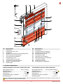
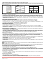
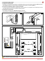
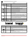
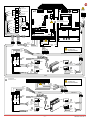
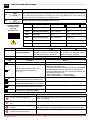
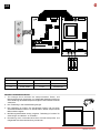
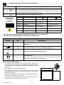

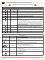
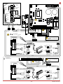
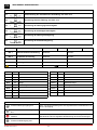
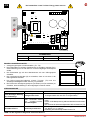
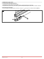
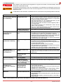
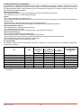
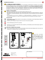
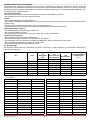

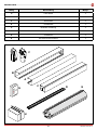
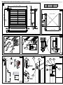
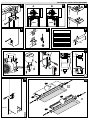
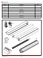

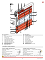


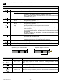

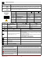

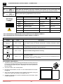
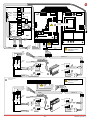
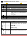
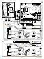
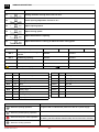
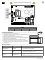
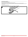
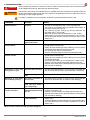
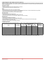
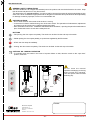
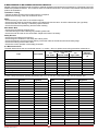
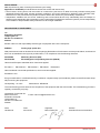

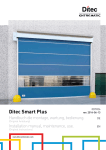
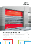

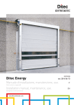

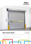
![Documentation technique [1.59 Mo]](http://vs1.manualzilla.com/store/data/006788543_1-357094a5e8900d31cb1a888bc107021d-150x150.png)