1
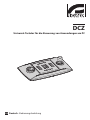
DCZ
Universal keyboard for PC software applications
EN English - Instructions manual
IT Italiano - Manuale di istruzioni
FR Francais - Manuel d'instructions
DE Deutsch - Bedienungslanleitung
DCZ
Universal keyboard for PC software applications
EN English - Instructions manual
Contents
ENGLISH
1.1 Typographical conventions................................................................................................................................. 5
2 Notes on copyright and information on trademarks................................................. 5
3 Safety rules.................................................................................................................... 5
4 Identification................................................................................................................. 6
4.1 Product description and type designation.................................................................................................... 6
4.2 Product markings.................................................................................................................................................... 6
5 Explanation of terminology......................................................................................... 6
5.2.1 Driver and configuration files............................................................................................................................................. 6
5.2.2 MSD Device (Mass Storage Device)................................................................................................................................. 6
5.2.3 HID Device (Human Interface Device)............................................................................................................................. 6
5.2.4 CDC Device (Communication Device Class).................................................................................................................. 6
5.2.5 Virtual com port (VCOM)...................................................................................................................................................... 6
5.2.6 Joystick HID (JOYHID)............................................................................................................................................................ 6
6 Preparing the product for use...................................................................................... 7
6.1 Contents and unpacking...................................................................................................................................... 7
6.2 Safely disposing of packaging material.......................................................................................................... 7
7 Installation..................................................................................................................... 7
7.1 Installing the upper panel . ................................................................................................................................. 7
7.2 Quick configuration of the keyboard............................................................................................................... 8
7.3 Switching on............................................................................................................................................................. 8
7.4 Installation in HID Joystick mode...................................................................................................................... 8
7.5 Installation in Virtual Com Port mode.............................................................................................................. 8
7.5.1 Installation on PC with Windows environment............................................................................................................ 8
7.5.1.1 Retrieval of the configuration file........................................................................................................................................................... 9
7.5.1.2 Keyboard connection and recognition................................................................................................................................................ 9
7.5.1.3 Modifying the serial port number in Windows.................................................................................................................................. 9
7.5.2 Removal . ................................................................................................................................................................................... 9
7.5.2.1 Incomplete removal.................................................................................................................................................................................... 9
7.5.3 Functional testing with Windows environment.........................................................................................................10
7.5.4 Installation with Linux environment..............................................................................................................................10
7.5.5 Functional testing with Windows environment.........................................................................................................10
8 Configuration............................................................................................................... 10
8.1 Identification ID.....................................................................................................................................................10
8.2 Setup procedure....................................................................................................................................................10
8.3 How to enter setup...............................................................................................................................................10
8.4 Keys............................................................................................................................................................................11
8.4.1 Key 1: Inverting the keyboard...........................................................................................................................................11
8.4.2 Key 3: Joystick calibration..................................................................................................................................................11
8.4.3 Keys 4 and 7: VCOM mode.................................................................................................................................................11
8.4.4 Keys 5 and 8: JOYHID Mode...............................................................................................................................................11
8.4.5 Key 6: Checking that the keys/ LEDs work ..................................................................................................................11
8.4.6 Key 9: Configuration reset . ...............................................................................................................................................11
3
EN - English - Instructions manual
1 About this manual......................................................................................................... 5
8.5 Use in HID Joystick mode...................................................................................................................................12
9 VCOM communication protocol................................................................................. 12
EN - English - Instructions manual
9.1 Key and LED layout...............................................................................................................................................12
9.2 Typographic conventions...................................................................................................................................13
9.3 Sintax of messages...............................................................................................................................................13
9.4 Messages from keyboard to PC........................................................................................................................13
9.5 Messages from PC to Keyboard ......................................................................................................................14
9.6 LED updates............................................................................................................................................................15
9.7 Lookup chart (for experts only)........................................................................................................................15
9.7.1 Lookup value index..............................................................................................................................................................15
9.7.2 Modifications to the lookup chart to move and change the number of joystick keys................................15
9.7.2.1 Creating shift keys in VCOM mode.......................................................................................................................................................16
9.7.2.2 Reduced modifications to the joystick default settings...............................................................................................................16
9.7.2.3 Substantial modifications to the joystick default settings..........................................................................................................17
9.7.3 Modifications to the lookup chart to define alias keys............................................................................................17
10 Maintaining and cleaning......................................................................................... 18
10.1 Plastic cover cleaning (PC)...............................................................................................................................18
11 Disposal of waste materials...................................................................................... 18
12 Troubleshooting........................................................................................................ 18
13 Technical data............................................................................................................ 19
13.1 General...................................................................................................................................................................19
13.2 Mechanical............................................................................................................................................................19
13.3 Electrical.................................................................................................................................................................19
13.4 Communications.................................................................................................................................................19
13.5 Protocols................................................................................................................................................................19
13.6 Operating system...............................................................................................................................................19
13.7 Environment.........................................................................................................................................................19
13.8 Compliance to......................................................................................................................................................19
14 Technical drawings.................................................................................................... 19
4
3 Safety rules
Before installing and using this unit, please read this
manual carefully. Be sure to keep it handy for later
reference.
hh
1.1 Typographical conventions
DANGER!
High level hazard.
Risk of electric shock. Disconnect the
power supply before proceeding with any
operation, unless indicated otherwise.
gg
WARNING!
Medium level hazard.
This operation is very important for the
system to function properly. Please read
the procedure described very carefully and
carry it out as instructed.
hh
INFO
Description of system specifications.
We recommend reading this part carefully
in order to understand the subsequent
stages.
jj
The manufacturer declines all responsibility
for any damage caused by an improper use
of the appliances mentioned in this manual.
Furthermore, the manufacturer reserves
the right to modify its contents without any
prior notice. The documentation contained
in this manual has been collected with great
care, the manufacturer, however, cannot
take any liability for its use. The same thing
can be said for any person or company
involved in the creation and production of
this manual.
• The device must be installed only and exclusively
by qualified technical personnel.
• Before any technical work on the appliance,
disconnect the power supply.
• Do not use power supply cables that seem worn
or old.
• Never, under any circumstances, make any
changes or connections that are not shown in
this handbook: improper use of the appliance
can cause serious hazards, risking the safety of
personnel and of the installation.
2 Notes on copyright and
information on trademarks
• Use only original spare parts. Not original spare
parts could cause fire, electrical discharge or other
hazards.
The quoted names of products or companies are
trademarks or registered trademarks.
• Before proceeding with installation check the
supplied material to make sure it corresponds
to the order specification by examining the
identification labels ("4.2 Product markings", page 6).
Microsoft®, Windows® 2000, Windows® XP, Windows®
Vista and the Windows® logo are trademarks
registered by Microsoft Corporation in the US and/or
other Countries.
Linux® is a trademark registered by Linus Torvalds in
the US and/or other Countries.
USBDView is a freeware program produced by NirSoft
(www.nirsoft.net).
5
EN - English - Instructions manual
1 About this manual
EN - English - Instructions manual
4 Identification
4.1 Product description and type
designation
DCZ is a dedicated keyboard used to control software
programs on Personal Computers.
This keyboard simplifies and rationalizes the user
interface quite remarkably and adds a joystick
and jog shuttle to the control system. It has been
conceived so that it can be used by both righthanded and left-handed users.
Every time the operator uses the keyboard, it will
generate an event:
• Pressing of a touch key;
• Release of a touch key;
• Movement of the joystick;
• Movement of the jog dial;
• Movement of the shuttle ring.
All keys are totally independent: the pressing
and release of keys is recognised, whatever the
combination used. The software application will
interpret the command.
The keyboard also has an internal buzzer and
back-lighting for the keys. The software application
manages the buzzer and back-lighting of keys.
It can be connected to a PC together with other
standard peripherals (standard keyboard, mouse,
videogame joystick etc.).
Patent Pending.
4.2 Product markings
See the label attached to the outside of the package.
5 Explanation of
terminology
5.2.1 Driver and configuration files
Software and configuration files requested by the
Operating System during installation to recognize
peripherals.
5.2.2 MSD Device (Mass Storage
Device)
USB peripheral device used to store and back-up
data. The most common MSD device is the USB
PenDrive. It does not require the installation of drivers
as it is recognized directly by the Operating System.
5.2.3 HID Device (Human Interface
Device)
USB peripheral device used to exchange information
with human beings. The definition also includes PC
keyboards, mouse, video game joystick and controls.
The HID peripheral device does not require the
installation of drivers as it is recognized directly by
the Operating System.
5.2.4 CDC Device (Communication
Device Class)
USB peripheral device used to exchange information
via serial channels.
When connected, the CDC peripheral device is
recognized by the OS which installs it without the
need for a driver (when using Linux) or after reading
a configuration file supplied by the peripheral
manufacturer (Windows).
5.2.5 Virtual com port (VCOM)
CDC device that emulates a standard serial port. This
is managed via a series of simple and consolidated
standard programming techniques which are
available for most programming languages. The
Windows OS will request a configuration file in order
to recognize the device during installation.
5.2.6 Joystick HID (JOYHID)
USB joystick that is recognized as a standard video
games joystick.
6
6 Preparing the product
for use
6.1 Contents and unpacking
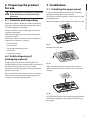
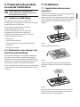
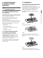
7.1 Installing the upper panel
In the standard keyboard the joystick is located on
the right and the jog shuttle on the left.
This layout can be changed to suit the needs of a lefthanded operator.
Remove the upper panel secured with adhesive tape.
When the product is delivered, make sure that the
package is intact and that there are no signs that it
has been dropped or scratched.
If there are obvious signs of damage, contact the
supplier immediately.
Keep the packaging in case you need to send the
product for repairs.
Check the contents to make sure they correspond
with the list of materials as below:
• DCZ keyboard
• Die cut sheets
• Transparent protective panel
Fig. 01
Remove the lower film.
• Quick Start
• Instructions manual
6.2 Safely disposing of
packaging material
The packaging material can all be recycled. The
installer technician will be responsible for separating
the material for disposal, and in any case for
compliance with the legislation in force where the
device is to be used.
Fig. 02
Choose the layout for the keyboard and stick the
adhesive panel, making sure that it does not touch
the keys.
Bear in mind that if the material has to be returned
due to a fault, using the original packaging for its
transport is strongly recommended.
Fig. 03
To confirm the layout and the operating mode follow
the selection procedure described in the following
paragraph.
7
EN - English - Instructions manual
Any change that is not expressly approved
by the manufacturer will invalidate the
guarantee.
hh
7 Installation
EN - English - Instructions manual
7.2 Quick configuration of the
keyboard
The DCZ keyboard can operate in two different
modes:
Mode
Emulation
Virtual com port (VCOM)
Virtual serial port (default)
Joystick Human Interface
Device (JOYHID)
Video-game joystick
Tab. 01
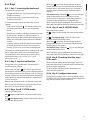
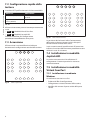
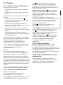
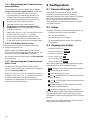
When switching on the keyboard, press the following
keys contemporaneously:
• SET + 4 : Virtual Com Port mode
• SET + 5 : HID Joystick mode.
Any previous change to the configuration will be lost.
Fig. 05
7.3 Switching on
The keyboard is correctly oriented when the LED bar
is on the upper part.
When the keyboard is switched on the backlit
keys briefly show the current configuration of the
keyboard:
Virtual Com Port mode.
When the keyboard is switched on, the central backlit
numeric keys show the firmware version and could
be needed in case of technical assistance.
7.4 Installation in HID Joystick
mode
The keyboard does not require installation. It is
automatically recognised by the operating system.
7.5 Installation in Virtual Com
Port mode
7.5.1 Installation on PC with Windows
environment
Installation consists in three phases:
• Retrieval of the configuration file
• Keyboard connection and recognition
Fig. 04
8
HID Joystick mode.
• Change of the serial port number.
• Click on Property for the required port.
Press and hold the ESC key and connect the
keyboard to the PC.
• Go to Port settings/Advanced and change the
port number in COM port number. Some ports
may indicate they are in use by other devices,
though this is not usually the case. If you select
a port in use check whether other devices (for
instance an analog modem) are already using it.
This will allow the keyboard to be recognised as a
MSD device on start-up: the OS recognizes it using
system drivers.
In Computer resources search for the relative device
(defined as Removable disk).
The device contains two files:
• xp_vista.inf for Windows Xp and Vista Operating
Systems;
• win2000.inf for Windows 2000 OS.
Copy the file required by the installed OS to the PC.
Disconnect the keyboard.
It is also possible to download the file from
http://www.videotec.com/dcz
7.5.1.2 Keyboard connection and
recognition
Connect the keyboard without pressing any keys. The
OS wizard procedure will ask for the driver: enter the
path to where the configuration file has been saved.
Follow the wizard instructions to complete the
operation.
7.5.1.3 Modifying the serial port number in
Windows
The Windows OS allows for mapping of the serial
ports: regardless of the hardware configuration, each
serial port can be assigned a COM number from 1 to
256.
When installing on Windows environment, the OS will
automatically assign a port number which may not
necessarily meet the needs of the user.
To change the serial port number:
• Connect and install the DCZ keyboard.
• Go to the settings in Control Panel/System/
Hardware/ Device Manager.
• Scroll the list of peripherals and select Ports (COM
and LPT): the USB CDC serial port emulation
(COMx) port corresponds to the DCZ keyboard.
• Press confirm and exit.
After changing the port number, the Device
Manager tab may still indicate the old COM number.
Close the Device Manager tab and then re-open it
again to see if the number has been changed.
7.5.2 Removal
If there is an error during installation or it has not
been completed correctly, the keyboard can be
removed from the device list.
• Connect the DCZ keyboard. A message may popup
to warn the user that the device was not installed
as an error occurred.
• Go to the settings in Control Panel/System/
Hardware/Peripheral Devices.
• Scroll the list of peripherals and select Ports (COM
and LPT):
• Select the USB CDC serial port emulation (COMx)
port .
• Select Uninstall in the Action menu and confirm.
• Disconnect the keyboard.
The next time the keyboard is connected, the
installation wizard will appear again, as indicated
in the sections above (Installation wizard for new
hardware).
7.5.2.1 Incomplete removal
If it is not possible to remove the port, or the
operation has not been completed,
we recommend using USBDView
(http://www.nirsoft.net/utils/usb_devices_view.html)
to uninstall the device.
Go to Options and select Display Disconnected
Devices , then identify the device with the VendorID
204f. Select or remove it using File/Uninstall
Selected Devices.
9
EN - English - Instructions manual
7.5.1.1 Retrieval of the configuration file
EN - English - Instructions manual
7.5.3 Functional testing with Windows
environment
Hyperterminal is used for this test (Start/Programs/
Accessories/Hyperterminal).
• Start Hyperterminal and name the connection at
will, now select the DCZ serial on the page that
appears on the screen. Any baudrate value is
accepted.
• Enable the echo of the characters (File/Properties/
Settings/ASCII Settings) in order to view what is
entered using the keyboard.
• Type in [Buzzer+] to activate the buzzer, type
[Buzzer-] to deactivate it. If the buzzer enables
and disables the keyboard it has been recognized
and is operating correctly.
7.5.4 Installation with Linux
environment
Linux does not require any driver to recognize the
keyboard.
Launch lsusb from the terminal to obtain the list of
connected USB devices: the keyboard is recognized
as a 204F:0101 device.
8 Configuration
8.1 Identification ID
The keyboard has no ID as the serial ports are
identified univocally by the OS. Even when more
than one keyboard is connected via a USB HUB to the
same USB port on the PC, they will be recognized as
separate serial ports (for instance COM3 and COM4).
8.2 Setup procedure
A specific key sequence allows users to access the
setup phase to:
• Set the keyboard orientation;
• Calibrate the joystick;
• Select the operating mode;
• Reset configuration to default values.
8.3 How to enter setup
• Press the START key;
• Press the LEARN key;
• Press the ESC key;
The keyboard is managed by the system file as a /
dev/ttyACM0 device.
• Release the ESC key;
7.5.5 Functional testing with Windows
environment
• Release the START key.
Minicom is used for these tests.
Launch the application on the terminal and request
the /dev/ttyACM0 device.
Type in [Buzzer+] to activate the buzzer, type
[Buzzer-] to deactivate it. If the buzzer enables
and disables the keyboard it has been recognized
and is operating correctly.
• Release the LEARN key;
The key LEDs will light up when setup has been
accessed successfully:
• ESC : Exit without changes;
• 1 : Invert the keyboard;
• 3 : Calibrate the joystick;
• 4 and 7 : VCOM mode (with or without reset of
the lookup chart);
• 5 and 8 : JOYHID mode (with or without reset of
the lookup chart);
• 6 : Functional test on keys and LEDs (in VCOM
mode);
• 9 : Reset configuration (VCOM mode).
Functions which have flashing keys are to be
used very carefully as they could lead to apparent
malfunctions of the keyboard.
After any option has been selected, the setup
procedure terminates automatically.
10
8.4 Keys
8.4.1 Key 1: Inverting the keyboard
• By right-handed users (joystick on the right, jog
shuttle on the left);
• By left-handed users (joystick on the left, jog
shuttle on the right).
(for experts only) Select key 7 to save any changes
made to the lookup chart. Some keys may not
necessarily be recognized as they were previously
assigned to the emulation of the joystick keys.
To invert the keyboard compared to the current
settings:
When setup has been completed, disconnect and
then reconnect the keyboard to enforce the changes.
• Enter setup and press 1 . The keyboard will save
the setting and return to its normal operating
mode
8.4.4 Keys 5 and 8: JOYHID Mode
• Remove the caption panel paying attention to the
fastening tabs, rotate it by 180° and replace it.
Key 5 : select JOYHID mode with reset of the lookup
chart.
• Adjust the feet on the bottom of the keyboard to
obtain the inclination required for each different
surface.
Key 8 : (for experts only) select JOYHID mode
without reset of the lookup chart
• Carefully remove the USB cable from the bottom
of the keyboard and insert it in the serpentine
making sure it is not a nuisance to the operator.
The inversion of the keyboard has nothing to do with
the PC application which must not be changed.
The orientation of the keyboard can be set using
VCOM commands [Orientation+] and
[Orientation-].
8.4.2 Key 3: Joystick calibration
Selecting JOYHID mode:
When key 5 is pressed, all the changes made to
the key lookup chart are cancelled and the default
configuration is reinstated.
(for experts only) Select key 8 to save any changes
made to the lookup chart.
When setup has been completed, disconnect and
then reconnect the keyboard to enforce the changes.
8.4.5 Key 6: Checking that the keys/
LEDs work
To calibrate the joystick:
When in VCOM mode, this function lights up a LED
when the relative key is pressed which indicates that
both are working properly.
Enter setup and press 3 . The LEDs in the centre of
the keyboard will flicker during the calibration phase.
To reinstate the standard mode, disconnect and
reconnect the keyboard.
Move the joystick for a few seconds as far as it will go,
in both a horizontal and vertical direction. Rotate the
knob clockwise and counter clockwise several times,
as far as it will go.
8.4.6 Key 9: Configuration reset
The joystick can be calibrated if it malfunctions.
The keyboard configuration is reset to default values
(VCOM mode). All changes made to the configuration
(e.g. the key lookup chart) will be lost.
Release the joystick to assess its position when idle.
After 5 seconds of inactivity, the keyboard will save
the values and confirm the calibration.
8.4.3 Keys 4 and 7: VCOM mode
Selecting VCOM mode:
Key 4 : Select VCOM mode with reset of the lookup
chart.
Key 7 : (for experts only) select VCOM mode without
reset of the lookup chart.
11
EN - English - Instructions manual
The keyboard can be used:
When key 4 is pressed, all the changes made to
the key lookup chart are cancelled and the default
configuration is reinstated (each key is assigned a
number which corresponds to its default logical
address).
9 VCOM communication
protocol
EN - English - Instructions manual
8.5 Use in HID Joystick mode
When the keyboard in in JOYHID mode, it is
recognized as a standard 4-axis 32 key joystick.
According to the USB specifications (ref. USB HID
Usage Tables, ver1.12, paragraph 4.2 Axis Usages) the
axes are assigned by default as follows:
Pan: X axis
Tilt: Y axis
When the keyboard is in VCOM mode it
communicates with the PC via a simplified ASCII
protocol. Printable characters are transmitted and any
numbers are transmitted as strings (not as decimal or
hexadecimal bytes).
No flow of hardware or software communication is
managed.
Zoom (rotation): Z axis
Shuttle ring (rotation): Rx axis
Jog dial (rotation): Not applicable.
On pressing a joystick key, the relative LED will light
up.
The PC application will open the serial port which
corresponds to the connected keyboard (the
baudrate and serial port configuration are irrelevant)
and it transmits/receives on this channel.The
keyboard responds to every command given by
the PC with an acknowledge message. Messages
transmitted by the keyboard do not require
acknowledgement by the PC application.
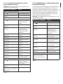
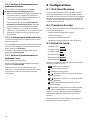
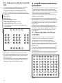
9.1 Key and LED layout
25
26
01
02
03
13
14
27
28
04
05
06
15
16
29
30
07
08
09
17
18
31
32
10
11
12
19
20
The DCZ keyboard manages a 72 key layout and the
corresponding LEDs (8 rows, each with 9 columns).
Regardless of the actual number of keys available
and used by the operator, each key/ LED coordinate
is always identified by the same 2 numbers: row (1..8)
and column (1..9).
When a key is pressed and released it transmits a
lookup chart value.
21
22
23
24
Fig. 06
It is possible to change both the number and position
of the joystick keys; follow the indications in the
chapter dedicated to the key lookup chart.
The functions of the joystick's keys are established
by the application. Refer to the relevant installer's
manual.
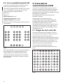
The lookup chart default values correspond to the
logical coordinates for each key:
11
12
13
14
15
16
17
18
19
21
22
23
24
25
26
27
28
29
31
32
33
34
35
36
37
38
39
41
42
43
44
45
46
47
48
49
51
52
53
54
55
56
57
58
59
61
62
63
64
65
66
67
68
69
71
72
73
74
75
76
77
78
79
81
82
83
84
85
86
87
88
89
Fig. 07
12
Example: On a default DCZ keyboard, the ESC key
is represented by code 13, the MONITOR key by
14, etc.
The DCZ keyboard transmits every event to the PC
and does not expect an acknowledge message.
The events are:
Event
Message
Parameters
By changing the value associated to each key on the
lookup chart, it is possible to redefine its function and
to allow the user to use keys with the same value.
Pressing of a
touch key
[K+val]
val: Value of the
key in the lookup
chart
9.2 Typographic conventions
Pressing of a
touch key +
shift
[K+val:shift]
val: Value of the
key in the lookup
chart
The following typographic conventions are used in
the protocol described below:
• [messages]: Transmitted message
• variable_parameter: Variable parameter
inside a message
• ±: Plus or minus sign.
9.3 Sintax of messages
The messages sent to and from the PC consist in
printable characters (from ASCII 32 to ASCII 127
codes, excluding ASCII 91 and 93) which are delimited
by brackets [ and ]:
• [ (ASCII 91) Open square bracket, STX start of
transmission
• Message text of variable length
• [ (ASCII 93) Closed square bracket, STX start of
transmission
Given the type of messages transmitted and the
quality of the USB communication, no checksum
system is foreseen.
Example: When the ESC key is pressed (row
1, column 3) the default keyboard will transmit
[K+13]:
EN - English - Instructions manual
If the keyboard is rotated by 180°, the configuration
remains unaltered and there is no change from a PC
application point of view.
9.4 Messages from keyboard to PC
shift: Pressed
"shift" keys (‘1’..’8’)
Release of a
touch key
[K-val]
val: Value of the
key in the lookup
chart
Pressing a
"shift" key
[H+shift]
shift: Number of
"shift" key (‘1’..’8’)
Releasing a
"shift" key
[H-shift]
shift: Number of
"shift" key (‘1’..’8’)
Movement of
the joystick,
[J±pp±tt±zz]
±pp, ±tt, ±zz: Pan,
tilt, zoom position
-07..+07
Movement of
the shuttle
[S±aa]
±aa: Rotation angle
-70°..+70°
Movement of
the jog
[D+1]
Clockwise rotation
by one click (10
clicks per turn
angle)
Movement of
the jog
[D-1]
Counter clockwise
rotation by one
click (10 clicks per
turn angle)
Tab. 02
• [: Identifies the start of the message
• K+: Pressed key
• 13: Key lookup value (row 1, column 3)
• ]: Identifies the end of the message.
13
EN - English - Instructions manual
9.5 Messages from PC to Keyboard
All the messages transmitted from the PC to the keyboard are confirmed by the DCZ keyboard by an
acknowledge message. The messages from PC to Keyboard are:
Command
Acknowledgment
by DCZ
Meaning
[Status?]
[Ready]
Keyboard online presence test
[Model?]
[Model=...]
Keyboard model and firmware version
[Firmware?]
[Firmware=...]
[Date?]
[Date=...]
[Led+rc]
[LedrcSet]
Led on
[Led-rc]
[LedrcSet]
Led off
[Led-Al]
[LedAlSet]
Switching off all LED's
[Led/rc]
[LedrcSet]
Led blinking
[LedRowrsssssssss]
[LedRowSet]
rc: Row 1...8 column 1…9*
rc: Row 1...8 column 1…9*
rc: Row 1...8 column 1…9*
Led row setting
r: Row 1..8
sssssssss: LED row status (+ on. – off, / blinking).
[LedImmediate]
[LedImmediateSet]
Immediate LED
("9.6 LED updates", page 15)
[LedDelayed]
[LedDelayedSet]
Delayed LED update
("9.6 LED updates", page 15)
[LedUpdate]
[LedUpdateDone]
LED update
("9.6 LED updates", page 15)
[LedCopy]
[LedCopyDone]
LED status copy
("9.6 LED updates", page 15)
[Buzzer+]
[BuzzerSet]
Start buzzer
[Buzzer-]
[BuzzerSet]
Stop buzzer
[Buzzer/]
[BuzzerSet]
Alternated start buzzer
[Orientation±]
[OrientationOk]
Keyboard orientation:
+ Joystick on the right, jog shuttle on the left
- Joystick on the left, jog shuttle on the right
[JoyDirX±]
[JoyDirOk]
[JoyDirY±]
Positive direction of the joystick axis: allows you to invert the
direction of the individual joystick axis.
X+: To the right (default), X-: To the left
[JoyDirZ±]
Y+: Upwards (default), Y-: Downwards,
Z+: Clockwise (default), Z-: Counter clockwise
[LookupWriterc,val]
[Lookup(rc)<-val]
Definition of the val value for the rc key* in the lookup chart
("9.7 Lookup chart (for experts only)", page 15)
[LookupReadrc]
[Lookup(rc)=val]
Lookup value read set for a logical coordinate key rc* ("9.7
Lookup chart (for experts only)", page 15)
[BlockModeStart]
[BlockModeStart]
This allows you to modify the configuration without using the
memory following multiple changes in values
[BlockModeEnd]
[BlockModeEnd]
This saves the last modified values [BlockModeStart]
Tab. 03
14
* The coordinates refer to the logical address of the LEDs, and not the value set in the lookup chart.
9.6 LED updates
If it is necessary to set a number of LEDs at the same
time, there may be an update delay mainly due to the
asynchronous communication between the keyboard
and the PC.
• Have more keys which are acknowledged as the
same key;
• Change the default position and the number of
joystick keys in JOYHID mode.
9.7.1 Lookup value index
The lookup values range from 0.to 65535.
A temporary buffer is used to avoid a delay of this
kind: after setting the temporary buffer values,
an update operation is performed so that the
contemporary change of all the modified LEDs is
visible.
Certain value intervals have a special meaning:
The following commands are used to this purpose:
• 1001..1008: Shift Key descriptions;
Command
Meaning
• 0: Disabled key;
• 1..99: Normal key, the value is sent when the key is
pressed and released;
• 50011..50089: Definition of multiple keys;
[LedImmediate] The update of the LED is immediate
• 60001..60032: Assigning of keys in JOYHID mode;
[LedDelayed]
• 60101..60103: For internal use, not available.
The update of the LEDs is delayed
until the first command is received
[LedUpdate].
In the meantime, all the [Led+xx],
[Led-xx] and [Led/xx]
commands are memorized in a
temporary buffer.
[LedUpdate]
The temporary buffer is copied
to the active buffer and all the
modification made in the meantime
are now visible
[LedCopy]
The active buffer copies back to the
temporary buffer
Tab. 04
9.7 Lookup chart (for experts
only)
Each key is assigned a value found on the key
lookup. The default value corresponds to the logical
coordinates of the key (for instance, the Esc key row
1, column 3, corresponds to a value of 13).
The LookupWrite command allows you to modify
the value assigned to a key.
The changing of lookup values can cause
apparent system malfunctions in the event
that it is necessary to replace the keyboard
at a later date. It is highly recommended to
document any modifications made.
hh
If a value of 01-99 is set, the corresponding code will
be sent by the keyboard when the key is pressed/
released in VCOM mode.
By setting a value between 1001-1008, the key
becomes a shift key. If any key is pressed while one
or more shift keys are pressed the message [K+xx]
changes to [K+xx:pressed_shift_list].
More than one shift key can be contemporaneously
pressed at any time.
If a value of 500rc (rc within the range of 11..89) is
set, this creates an alias and links the behaviour of the
key to another rc. logical coordinate key. This allows
you to manage a number of keys with the same
behaviour as if they were one single key.
If a value of 600nn (nn in the range of 01-32) is set,
the key will be assigned to the corresponding joystick
key nn in JOYHID mode.
9.7.2 Modifications to the lookup chart
to move and change the number of
joystick keys.
Modification to the lookup chart allows you to
change the position or the number of joystick keys
when in JOYHID mode.
15
EN - English - Instructions manual
The effect of the [Led+xx], [Led-xx] abe [Led/xx]
commands is usually immediate.
Changing lookup values enables you to:
9.7.2.1 Creating shift keys in VCOM mode
EN - English - Instructions manual
The keyboard can have up to 8 shift keys, used to
change the behaviour of ordinary keys.
Example: Transform key 86 into shift key number 1,
and key 87 into shift key number 7.
Operation / Command
Effect
9.7.2.2 Reduced modifications to the
joystick default settings
Example: If you want to maintain most of the central
group of keys, move key 1, create a double key for
number 2.
Operation / Command
Effect
Enter the programming settings
Enter the programming settings
Select 4 It switches to VCOM mode
resetting the joystick
lookup chart
Select 5 Resets the JOYHID key
chart to default settings
It restarts in VCOM mode
Disconnect and reconnect the
keyboard
It restarts in JOYHID mode
Disconnect and reconnect the
keyboard
[BlockModeStart]
Command
This allows you to
modify the internal
memory without using
it for multiple writing
commands.
Select 7 It switches to VCOM mode
without resetting the
joystick lookup chart
It restarts in VCOM mode
[LookupWrite86,1001]
Command
Creates the shift key 1
changing the behaviour of
key on row 8, column 6
Disconnect and reconnect the
keyboard
[BlockModeStart]
Command
[LookupWrite87,1007]
Command
Creates the shift key 7
changing the behaviour of
key on row 8, column 7
This allows you to
modify the internal
memory without using
it for multiple writing
commands.
[BlockModeEnd]
Command
Saves the modifications to
the internal memory
[LookupWrite34,0]
Command
Cancels key 1 from the
default position (row 3,
column 4)
Enter the programming settings again
Tab. 05
To check the correct definition of the shift keys:
[LookupWrite31,60001] Assigns key 1 (60001)
to the key on row 3,
Command
column 1
• Press ESC (key 1,3) without any shift key: The
keyboard sends the code [K+13];
[LookupWrite32,60002] Creates a second 2 key on
row 3, column 2
Command
• Press INFO (key in line 8, column 6, defined as
shift number 1) and ESC : The key sends the code
[K+13:1]. The shift keys that have been pressed
are identified by the colon;
Enter the programming settings
• Press SHIFT (arrow-up symbol, key in line 8,
column 7, defined as shift number 7) and ESC :
The keyboard sends the code [K+13:7];
• Press INFO , SHIFT and ESC : The keyboard
sends the code [K+13:17].
[BlockModeEnd]
Command
Select 8 Switches to JOYHID mode
without resetting the
lookup chart that has just
been modified
Disconnect and reconnect the
keyboard
It restarts in JOYHID mode
Check that the corresponding
LEDs come on when the keys
are pressed
Tab. 06
16
Saves the modifications to
the internal memory
9.7.3 Modifications to the lookup chart
to define alias keys
Example: If you want to use just 8 joystick keys on
the left side of the keyboard.
It is possible to have several keys that all perform the
same commands (e.g. the shift keys). If a series of
alias keys are pressed together at the same time, the
pressed key event ([K+xx]) is only transmitted the
first time it is pressed; the released key event ([Kxx]) is only transmitted when all the keys with the
same alias have also been released.
Operation / Command
Effect
Enter the programming settings
Select 5 Resets the JOYHID key
chart to default settings
Disconnect and reconnect the
keyboard
It restarts in JOYHID mode
Enter the programming settings again
Select 4 It switches to VCOM mode
resetting the lookup chart
(no keys valid for the
joystick)
Disconnect and reconnect the
keyboard
It restarts in VCOM mode
[BlockModeStart]
command
This allows you to
modify the internal
memory without using
it for multiple writing
commands.
[LookupWrite31,60001] Creates key 1 on row 3,
column 1
Command
[LookupWrite32,60002] Creates key 2 on row 3,
column 2
Command
[LookupWrite41,60003] Creates key 3 on row 4,
column 1
Command
[LookupWrite42,60004] Creates key 4 on row 4,
column 2
Command
[LookupWrite51,60005] Creates key 5 on row 5,
column 1
Command
Example: The 5 bottom keys on the keyboard act as if
they are the same key.
Operation / Command
Effect
Enter the programming settings
Select 4 Switches to VCOM mode
resetting the lookup chart
Disconnect and reconnect the
keyboard
It restarts in VCOM mode
[BlockModeStart]
Command
This allows you to
modify the internal
memory without using
it for multiple writing
commands.
[LookupWrite84,50083] The key on row 8, column
4, is an alias of the key on
Command
row 8, column 3
[LookupWrite85,50083] The key on row 8, column
5, is an alias of the key on
Command
row 8, column 3
[LookupWrite86,50083] The key on row 8, column
6, is an alias of the key on
Command
row 8, column 3
[LookupWrite52,60006] Creates key 5 on row 5,
column 2
Command
[LookupWrite87,50083] The key on row 8, column
7, is an alias of the key on
Command
row 8, column 3
[LookupWrite61,60007] Creates key 7 on row 6,
column 1
Command
[BlockModeEnd]
Command
[LookupWrite62,60008] Creates key 8 on row 6,
column 2
Command
Enter the programming settings
[BlockModeEnd]
Command
Saves the modifications to
the internal memory
Enter the programming settings
Select 8 Switches to JOYHID mode
without resetting the
lookup chart that has just
been modified
Disconnect and reconnect the
keyboard
It restarts in JOYHID mode
Saves the modifications to
the internal memory
Check that when the 5 lower
keys are pressed, they all
transmit the same message
[K+83]
Tab. 08
Check that the corresponding
LEDs come on when the keys
are pressed
Tab. 07
17
EN - English - Instructions manual
9.7.2.3 Substantial modifications to the
joystick default settings
EN - English - Instructions manual
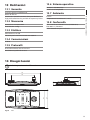
10 Maintaining and
cleaning
10.1 Plastic cover cleaning (PC)
We suggest to use neutral soap diluted with water
or specific products for lens cleaning applied with a
soft cloth.
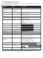
Problem
The installation
procedure was
not successful and
Windows does
not allow you
to complete the
operation
Possible causes and
solutions
Option 01:
• Connect the keyboard anyway
and ignore the error message;
• Go to Control Panel/System/
Hardware/Device manager and
identify Ports (LPT and COM);
• Select the keyboard;
Avoid ethyl alcohol, solvents, hydrogenated
hydrocarbide, strong acid and alkali. Such
products may irreparably damage the
surface.
hh
• Right click on the description of
the keyboard and select Uninstall
from the popup menu;
• Now reinstall it again.
Option 02:
11 Disposal of waste
materials
• Use USBDView to view the USB
devices installed
(http://www.nirsoft.net/utils/
usb_devices_view.html);
• Enable Option/Display
Disconnected Devices;
This symbol mark and recycle system
are applied only to EU countries and not
applied to the countries in the other area of
the world.
nn
• Uninstall it using File/Uninstall
Selected Devices;
• Now reinstall it again.
Your product is designed and manufactured with
high quality materials and components which can be
recycled and reused.
This symbol means that electrical and electronic
equipment, at their end-of-life, should be disposed of
separately from your household waste.
The LED and key
coordinates do not
correspond to your
requirements
In the European Union there are separate collection
systems for used electrical and electronic products.
• Now rotate the upper panel and
move the support feet and the
cable on the bottom shell.
12 Troubleshooting
See chapter "7 Installation", page 7.
The keyboard is
connected via a
hub and will not
switch on
Connect the keyboard directly to
the PC or only use a hub which is
powered separately and can supply
500mA to each port.
When the keyboard
is connected, the
other connected
USB devices switch
off or reset
The USB power supplied by
the PC does not meet required
specifications.
18
Option 02:
• The lookup chart has been
modified;
Possible causes and
solutions
The INF file is
requested during
installation
Connect the keyboard to another
USB port or use a hub that supplies
500mA per port.
• The keyboard has probably been
inverted and must be rotated
by 180°;
• In VCOM mode transmit
the [Orientation+] or
[Orientation-] command or
launch the setup procedure and
press 1 to invert it;
Please dispose of this equipment at your local
Community waste collection or Recycling centre.
Problem
Option 01:
• Launch the setup procedure.
Press 4 to enable VCOM mode
and to reset the keyboard to
factory settings.
Tab. 09
13.6 Operating system
13.1 General
Windows™ XP, 2000, Vista
38 backlit rubber keys
13.7 Environment
Linux™ and compatible operating systems
Alarm buzzer
Supplied with instructions manual, driver for Windows™,
pre-cut sheets, plastic protecting layer
Indoor
13.2 Mechanical
13.8 Compliance to
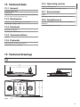
Dimensions: 379x89x224mm (15x3.5x8.8in)
EN55022 according to Class B, EN50130-4, EN61000-6-3,
EN60950-1
Operating temperature: 0°C / +45°C (+32°F / +113°F)
Unit Weight: 1.35kg / 3.0lb
FCC according to part 15 Class B
13.3 Electrical
Powered via USB port
Consumption: 350mA max
13.4 Communications
USB 2.0
13.5 Protocols
Dedicated Virtual Com Port protocol
Joystick HID 32 keys emulation
14 Technical drawings
The values are in millimeters.
jj
379
Fig. 08
49
224
205
34
89
253
DCZ
19
EN - English - Instructions manual
13 Technical data
VIDEOTEC S.p.A.
www.videotec.com
Printed in Italy
MNVCDCZ_1051_EN
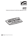
DCZ
Tastiera universale per il controllo di applicazioni su PC
IT Italiano - Manuale di istruzioni
Sommario
ITALIANO
1 Informazioni sul presente manuale............................................................................. 5
1.1 Convenzioni tipografiche..................................................................................................................................... 5
4.1 Descrizione e designazione del prodotto...................................................................................................... 6
4.2 Marcatura del prodotto......................................................................................................................................... 6
5 Spiegazione dei termini................................................................................................ 6
5.2.1 Driver e File di configurazione............................................................................................................................................ 6
5.2.2 Dispositivo MSD (Mass Storage Device)......................................................................................................................... 6
5.2.3 Dispositivo HID (Human Interface Device).................................................................................................................... 6
5.2.4 Dispositivo CDC (Communication Device Class)......................................................................................................... 6
5.2.5 Virtual Com Port (VCOM)...................................................................................................................................................... 6
5.2.6 Joystick HID (JOYHID)............................................................................................................................................................ 6
6 Preparazione del prodotto per l'utilizzo..................................................................... 7
6.1 Contenuto e disimballaggio................................................................................................................................ 7
6.2 Smaltimento in sicurezza dei materiali di imballaggio.............................................................................. 7
7 Installazione.................................................................................................................. 7
7.1 Applicazione del pannello superiore .............................................................................................................. 7
7.2 Configurazione rapida della tastiera................................................................................................................ 8
7.3 Accensione................................................................................................................................................................ 8
7.4 Installazione in modalità Joystick HID............................................................................................................. 8
7.5 Installazione in modalità Virtual Com Port..................................................................................................... 8
7.5.1 Installazione in ambiente Windows................................................................................................................................. 8
7.5.1.1 Prelievo del file di configurazione.......................................................................................................................................................... 9
7.5.1.2 Collegamento e riconoscimento della tastiera.................................................................................................................................. 9
7.5.1.3 Modifica del numero di porta seriale in Windows............................................................................................................................ 9
7.5.2 Rimozione . ............................................................................................................................................................................... 9
7.5.2.1 Rimozione incompleta............................................................................................................................................................................... 9
7.5.3 Verifica di funzionamento in ambiente Windows.....................................................................................................10
7.5.4 Installazione in ambiente Linux.......................................................................................................................................10
7.5.5 Verifica di funzionamento in ambiente Linux.............................................................................................................10
8 Configurazione............................................................................................................ 10
8.1 ID di identificazione..............................................................................................................................................10
8.2 Procedura di setup................................................................................................................................................10
8.3 Entrata in setup......................................................................................................................................................10
8.4 Tasti.............................................................................................................................................................................11
8.4.1 Tasto 1: Inversione della tastiera......................................................................................................................................11
8.4.2 Tasto 3: Calibrazione del joystick.....................................................................................................................................11
8.4.3 Tasti 4 e 7: Modalità VCOM.................................................................................................................................................11
8.4.4 Tasti 5 e 8: Modalità JOYHID..............................................................................................................................................11
8.4.5 Tasto 6: Verifica funzionamento dei tasti/LED.............................................................................................................11
8.4.6 Tasto 9: Reset della configurazione.................................................................................................................................11
3
IT - Italiano - Manuale di istruzioni
2 Note sul copyright e informazioni sui marchi commerciali....................................... 5
3 Norme di sicurezza........................................................................................................ 5
4 Identificazione............................................................................................................... 6
8.5 Uso in modalità Joystick HID.............................................................................................................................12
9 Protocollo di comunicazione VCOM........................................................................... 12
IT - Italiano - Manuale di istruzioni
9.1 Mappa dei tasti e dei LED...................................................................................................................................12
9.2 Convenzioni tipografiche...................................................................................................................................13
9.3 Sintassi dei messaggi...........................................................................................................................................13
9.4 Messaggi da Tastiera a PC...................................................................................................................................13
9.5 Messaggi da PC a Tastiera...................................................................................................................................14
9.6 Aggiornamento dei LED.....................................................................................................................................15
9.7 Tabella di lookup (solo per esperti).................................................................................................................15
9.7.1 Significato dei valori di lookup.........................................................................................................................................15
9.7.2 Modifica della tabella di lookup per spostare e cambiare il numero dei tasti joystick................................15
9.7.2.1 Creazione di tasti di shift in modalità VCOM....................................................................................................................................16
9.7.2.2 Modifiche ridotte della configurazione di default del joystick..................................................................................................16
9.7.2.3 Modifiche sostanziali della configurazione di default del joystick...........................................................................................17
9.7.3 Modifica della tabella di lookup per definire tasti alias...........................................................................................17
10 Manutenzione e pulizia............................................................................................ 18
10.1 Pulizia delle parti in plastica (PC)..................................................................................................................18
11 Smaltimento dei rifiuti.............................................................................................. 18
12 Troubleshooting........................................................................................................ 18
13 Dati tecnici................................................................................................................. 19
13.1 Generale.................................................................................................................................................................19
13.2 Meccanica..............................................................................................................................................................19
13.3 Elettrico..................................................................................................................................................................19
13.4 Comunicazioni.....................................................................................................................................................19
13.5 Protocolli................................................................................................................................................................19
13.6 Sistema operativo...............................................................................................................................................19
13.7 Ambiente...............................................................................................................................................................19
13.8 Conformità............................................................................................................................................................19
14 Disegni tecnici........................................................................................................... 19
4
1 Informazioni sul presente
manuale
1.1 Convenzioni tipografiche
PERICOLO!
Pericolosità elevata.
Rischio di scosse elettriche. Togliere
l'alimentazione prima di procedere con le
operazioni, salvo diversa indicazione.
gg
ATTENZIONE!
Pericolosità media.
L'operazione è molto importante per il
corretto funzionamento del sistema. Si
prega di leggere attentamente la procedura
indicata e di eseguirla secondo le modalità
previste.
hh
INFO
Descrizione delle caratteristiche del
sistema.
Si consiglia di leggere attentamente per
comprendere le fasi successive.
jj
2 Note sul copyright e
informazioni sui marchi
commerciali
I nomi di prodotto o di aziende citati sono marchi
commerciali o marchi commerciali registrati
appartenenti alle rispettive società.
Il produttore declina ogni responsabilità
per eventuali danni derivanti da un
uso improprio delle apparecchiature
menzionate in questo manuale. Si
riserva inoltre il diritto di modificarne il
contenuto senza preavviso. Ogni cura è
stata posta nella raccolta e nella verifica
della documentazione contenuta in questo
manuale, tuttavia il produttore non può
assumersi alcuna responsabilità derivante
dall'utilizzo della stessa. Lo stesso dicasi
per ogni persona o società coinvolta nella
creazione e nella produzione di questo
manuale.
hh
• L'installazione e la manutenzione del dispositivo
deve essere eseguita solo da personale tecnico
qualificato.
• Prima di effettuare interventi tecnici
sull'apparecchio togliere l'alimentazione elettrica.
• Non utilizzare cavi di alimentazione con segni di
usura o invecchiamento.
• Non effettuare per nessun motivo alterazioni o
collegamenti non previsti in questo manuale:
l'uso di apparecchi non idonei può portare a
gravi pericoli per la sicurezza del personale e
dell'impianto.
• Utilizzare solo parti di ricambio originali. Pezzi di
ricambio non originali potrebbero causare incendi,
scariche elettriche o altri pericoli.
• Prima di procedere con l'installazione controllare
che il materiale fornito corrisponda alle specifiche
richieste esaminando le etichette di marcatura ("4.2
Marcatura del prodotto", pagina 6).
Microsoft®, Windows® 2000, Windows® XP, Windows®
Vista e il logo Windows® sono marchi di Microsoft
Corporation negli Stati Uniti e/o in altri Paesi.
Linux® è un marchio registrato di Linus Torvalds negli
Stati Uniti e/o in altri Paesi.
USBDView è un freeware gratuito prodotto da NirSoft
(www.nirsoft.net).
5
IT - Italiano - Manuale di istruzioni
Prima di installare e utilizzare questa unità, leggere
attentamente questo manuale. Conservare questo
manuale a portata di mano come riferimento futuro.
3 Norme di sicurezza
IT - Italiano - Manuale di istruzioni
4 Identificazione
5 Spiegazione dei termini
4.1 Descrizione e designazione
del prodotto
5.2.1 Driver e File di configurazione
DCZ è una tastiera dedicata al controllo di
applicazioni su Personal Computer.
Questa tastiera consente una notevole
semplificazione e razionalizzazione dell’interfaccia
utente aggiungendo un joystick e un jog shuttle al
sistema di controllo. La sua particolare concezione
ne permette l’uso sia da parte di destrimani che di
mancini.
Software e File di configurazione richiesti al momento
dell’installazione per il riconoscimento di una
periferica da parte del Sistema Operativo.
5.2.2 Dispositivo MSD (Mass Storage
Device)
Periferica USB che permette la memorizzazione di
dati. Il dispositivo MSD più conosciuto è la PenDrive
USB. Non necessita di driver di installazione perché
direttamente riconosciuta dal Sistema Operativo.
Ogni interazione dell’operatore con la tastiera genera
un evento:
5.2.3 Dispositivo HID (Human Interface
Device)
• Pressione di un tasto;
Periferica USB dedicata allo scambio di informazioni
con esseri umani. La definizione comprende tra l’altro
tastiere PC, mouse, joystick e controlli da videogioco.
• Rilascio di un tasto;
• Movimento del joystick;
• Movimento del jog dial (rotore interno);
• Movimento dello shuttle ring (ghiera esterna).
I tasti sono completamente indipendenti: la pressione
ed il rilascio dei tasti sono riconosciute in qualsiasi
combinazione. La loro interpretazione è interamente
a carico dell’applicazione.
La tastiera è dotata di buzzer interno e di
retroilluminazione dei tasti. Le attivazioni di buzzer
e della retroilluminazione dei tasti sono stabilite
dall’applicazione.
Può essere collegata ad un PC contemporaneamente
alle normali periferiche (tastiere standard, mouse,
joystick da videogiochi, ecc.).
Patent Pending.
4.2 Marcatura del prodotto
Vedere l’etichetta posta sull’esterno dell’imballo.
La periferica HID non necessita di driver di
installazione perché direttamente riconosciuta dal
Sistema Operativo.
5.2.4 Dispositivo CDC (Communication
Device Class)
Periferica USB dedicata allo scambio di informazioni
attraverso un canale seriale.
Al momento della connessione la periferica CDC
viene riconosciuta dal Sistema Operativo che la
installa senza la necessità di un driver (nel caso di
Linux) o previa lettura di un file di configurazione
fornito dal produttore della periferica (Windows).
5.2.5 Virtual Com Port (VCOM)
Dispositivo CDC che emula una porta seriale
standard. Viene gestito tramite una serie di tecniche
standard di programmazione semplici e consolidate
disponibili per la maggior parte dei linguaggi di
programmazione. Durante l’installazione il Sistema
Operativo Windows richiede un File di configurazione
per poter riconoscere il dispositivo.
5.2.6 Joystick HID (JOYHID)
Joystick USB che viene riconosciuto come Joystick
standard per videogiochi.
6
6 Preparazione del
prodotto per l'utilizzo
6.1 Contenuto e disimballaggio
Alla consegna del prodotto verificare che l'imballo
sia integro e non abbia segni evidenti di cadute o
abrasioni.
7.1 Applicazione del pannello
superiore
L'orientamento predefinito della tastiera prevede il
joystick a destra ed il jog shuttle a sinistra.
IT - Italiano - Manuale di istruzioni
Qualsiasi cambiamento non espressamente
approvato dal costruttore fa decadere la
garanzia.
hh
7 Installazione
Questo orientamento può essere eventualmente
cambiato per far fronte alle esigenze particolari
dell'operatore mancino.
Rimuovere il pannello superiore fissato con il nastro
adesivo
In caso di evidenti segni di danno all'imballo
contattare immediatamente il fornitore.
Conservare l'imballo nel caso sia necessario inviare il
prodotto in riparazione.
Controllare che il contenuto sia rispondente alla lista
del materiale sotto indicata:
• Tastiera DCZ
• Fogli fustellati bianchi
• Pannello plastico trasparente di protezione
• Quick Start
• Manuale di istruzioni
Fig. 01
Togliere la pellicola inferiore
6.2 Smaltimento in sicurezza dei
materiali di imballaggio
I materiali d'imballo sono costituiti interamente da
materiale riciclabile. Sarà cura del tecnico installatore
smaltirli secondo le modalità di raccolta differenziata
o comunque secondo le norme vigenti nel Paese di
utilizzo.
Fig. 02
Si ricorda comunque che in caso di ritorno di
materiale con malfunzionamenti è consigliato
l'imballaggio originale per il trasporto.
Scegliere l'orientamento della tastiera ed applicare il
pannello adesivo facendo attenzione che questo non
tocchi i tasti.
Fig. 03
Confermare la scelta dell'orientamento e della
modalità di funzionamento seguendo la procedura di
selezione indicata al prossimo paragrafo.
7
7.2 Configurazione rapida della
tastiera
IT - Italiano - Manuale di istruzioni
La tastiera DCZ può funzionare in 2 diverse modalità:
Modalità
Emulazione
Virtual com port (VCOM)
Porta seriale virtuale
(default)
Joystick Human Interface
Device (JOYHID)
Joystick da videogiochi
Tab. 01
All'accensione tenere premuti contemporaneamente
i tasti:
• SET + 4 : Modalità Virtual Com Port
• SET + 5 : Modalità Joystick HID.
Eventuali modifiche alla configurazione
precedentemente effettuate sono perse.
7.3 Accensione
All'accensione i tasti retroillluminati indicano
brevemente la configurazione attuale della tastiera:
Fig. 05
Modo Virtual Com Port.
La posizione dei led accesi indica l'orientamento
della tastiera e devono essere rivolti in alto per il
funzionamento corretto della stessa.
I tasti numerici centrali retroilluminati all'accensione
indicano la versione del firmware e potrebbero essere
richiesti in caso di assistenza.
7.4 Installazione in modalità
Joystick HID
La tastiera non necessita di installazione. Al
collegamento il sistema operativo la riconosce
automaticamente.
7.5 Installazione in modalità
Virtual Com Port
7.5.1 Installazione in ambiente
Windows
L’installazione consiste in tre fasi:
• Prelievo del file di configurazione;
Fig. 04
Modo Joystick HID.
• Collegamento e riconoscimento della tastiera;
• Modifica del numero di porta seriale della porta
seriale.
8
• Accedere alle Proprietà della porta.
Collegare la tastiera al PC tenendo premuto il
tasto ESC .
• In Impostazioni della porta/Avanzate modificare
il numero della porta in Numero porta COM.
Alcune porte potrebbero essere definite come
in uso da parte di altri dispositivi anche se
solitamente non lo sono. Nel caso si selezioni una
porta in uso fare attenzione che altri dispositivi (ad
esempio un modem analogico) non l’abbiano già
impegnata.
In questo modo all’avvio la tastiera viene identificata
come dispositivo MSD: il Sistema Operativo la
riconosce usando driver di sistema.
In Risorse del computer cercare il dispositivo
corrispondente (definito come Disco removibile).
Il dispositivo contiene due file:
• Confermare ed uscire.
• xp_vista.inf per i sistemi operativi Windows Xp e
Vista;
Al cambio del numero porta il pannello Gestione
Periferiche potrebbe mostrare il vecchio numero
COM.
• win2000.inf per il sistema operativo Windows
2000.
Copiare sul PC il file corrispondente al sistema
operativo in uso.
Scollegare la tastiera.
In alternativa scaricare il file all’indirizzo
http://www.videotec.com/dcz
7.5.1.2 Collegamento e riconoscimento
della tastiera
Collegare la tastiera senza premere alcun tasto. La
procedura guidata del Sistema Operativo chiede il
driver: indicare il percorso dov’è stato salvato il file di
configurazione.
Procedere con l’installazione seguendo la procedura
guidata.
7.5.1.3 Modifica del numero di porta seriale
in Windows
Il Sistema Operativo Windows consente la mappatura
delle porte seriali: indipendentemente dalla
configurazione hardware a ciascuna porta seriale può
essere assegnato un numero COM da 1 a 256.
All’installazione in ambiente Windows il Sistema
Operativo assegna automaticamente un numero
di porta che può non corrispondere alle esigenze
dell’utilizzatore.
Per cambiare il numero di porta seriale:
• Collegare e installare la tastiera la tastiera DCZ.
• Accedere alle impostazioni del Pannello di
Controllo/Sistema/Hardware/Gestione
periferiche.
• Nell’elenco delle periferiche individuare Porte
(COM e LPT): la porta USB CDC serial port
emulation (COMx) corrisponde alla tastiera DCZ.
Chiudere il pannello Gestione Periferiche e riaprirlo
per verificare che il numero sia stato cambiato.
7.5.2 Rimozione
In caso di installazione errata o incompleta è possibile
rimuovere la tastiera dalla lista delle periferiche.
• Collegare la tastiera DCZ. Un messaggio può
avvisare che l’installazione della periferica non è
riuscita a causa di un errore.
• Accedere alle impostazioni del Pannello di
Controllo/Sistema/Hardware/Gestione
periferiche.
• Nell’elenco delle periferiche individuare Porte
(COM e LPT).
• Selezionare la porta USB CDC serial port
emulation (COMx).
• Nel menù Azione scegliere Disinstalla e
confermare.
• Rimuovere la tastiera.
Alla successiva connessione della tastiera è
riproposta nuovamente tutta la sequenza di
installazione secondo quanto descritto in precedenza
(Installazione guidata di nuovo hardware).
7.5.2.1 Rimozione incompleta
Se la rimozione della porta non fosse possibile o
incompleta si consiglia di usare USBDView
(http://www.nirsoft.net/utils/usb_devices_view.html)
per la disinstallazione del dispositivo.
In Options attivare Display Disconnected Devices
e identificare il dispositivo con VendorID 204f.
Selezionarlo e rimuoverlo con File/Uninstall
Selected Devices.
9
IT - Italiano - Manuale di istruzioni
7.5.1.1 Prelievo del file di configurazione
7.5.3 Verifica di funzionamento in
ambiente Windows
IT - Italiano - Manuale di istruzioni
Per la verifica si usa Hyperterminal (Start/
Programmi/Accessori/Hyperterminal).
• All’avvio di Hyperterminal dare un nome qualsiasi
alla connessione e scegliere alla schermata
successiva la seriale corrispondente alla DCZ. Il
valore di baudrate è indifferente.
• Attivare l’echo dei caratteri (File/Proprietà/
Impostazioni/Impostazioni ASCII) per poter
visualizzare quanto viene digitato a tastiera.
• Digitare [Buzzer+] per attivare il cicalino,
[Buzzer-] per disattivarlo. Se il cicalino si attiva
e disattiva la tastiera è stata riconosciuta ed è
funzionante.
7.5.4 Installazione in ambiente Linux
La tastiera è riconosciuta in ambiente Linux senza
necessità di driver.
Lanciare lsusb da terminale per ottenere la lista dei
dispositivi USB collegati: la tastiera viene elencata
come dispositivo 204F:0101.
La tastiera viene gestita dal file system come
dispositivo /dev/ttyACM0.
7.5.5 Verifica di funzionamento in
ambiente Linux
Per la verifica si usa Minicom.
Aprire l’applicazione da terminale e richiedere il
dispositivo /dev/ttyACM0.
Digitare [Buzzer+] per attivare il cicalino,
[Buzzer-] per disattivarlo. Se il cicalino si attiva
e disattiva la tastiera è stata riconosciuta ed è
funzionante.
8 Configurazione
8.1 ID di identificazione
La tastiera non possiede un ID in quanto le porte
seriali sono identificate univocamente dal Sistema
Operativo. Anche nel caso più tastiere siano collegate
attraverso un HUB USB alla stessa porta USB del PC
saranno riconosciute come porte seriali diverse (ad
esempio COM3 e COM4).
8.2 Procedura di setup
Una sequenza particolare di tasti permette di entrare
in una fase di setup per:
• Settare l’orientamento della tastiera;
• Calibrare il joystick;
• Scegliere la modalità operativa;
• Resettare la configurazione ai valori di default.
8.3 Entrata in setup
• Premere il tasto START ;
• Premere il tasto LEARN ;
• Premere il tasto ESC ;
• Rilasciare il tasto ESC ;
• Rilasciare il tasto LEARN ;
• Rilasciare il tasto START .
L’entrata in setup è confermata dall’accensione dei
LED corrispondenti ai tasti:
• ESC : Uscita senza modifiche;
• 1 : Inversione della tastiera;
• 3 : Calibrazione del joystick;
• 4 e 7 : Modalità VCOM (con e senza reset della
tabella di lookup);
• 5 e 8 : Modalità JOYHID (con e senza reset della
tabella di lookup);
• 6 : Verifica funzionamento dei tasti e LED (in
modalità VCOM);
• 9 : Reset della configurazione (modalità VCOM).
Le funzioni caratterizzate da tasti lampeggianti
sono da usare con attenzione perché potrebbero
comportare apparenti malfunzionamenti della
tastiera.
Dopo la scelta di qualsiasi opzione la procedura di
setup termina automaticamente.
10
8.4 Tasti
8.4.1 Tasto 1: Inversione della tastiera
La tastiera può essere usata:
Per l’inversione della tastiera rispetto alla posizione
attuale:
(solo per esperti) Con 7 le eventuali modifiche
apportate alla tabella di lookup sono conservate.
Alcuni tasti potrebbero non essere più riconosciuti
perché precedentemente assegnati all’emulazione
dei tasti del joystick.
• Entrare in setup e premere 1 . La tastiera registra
l’impostazione e torna al funzionamento normale.
Dopo il termine del setup disconnettere e
riconnettere la tastiera per accettare la modifica.
• Rimuovere il pannello delle didascalie facendo
attenzione alle linguette di fissaggio e reinserirlo
dopo averlo ruotato di 180°.
8.4.4 Tasti 5 e 8: Modalità JOYHID
• Da mancini (joystick a sinistra, jog shuttle a destra).
• Aggiustare i piedini di appoggio sul fondo della
tastiera per mantenere la corretta inclinazione sul
piano di appoggio.
• Estrarre con delicatezza il cavo USB dal fondo della
tastiera e reinserirlo nella serpentina perché non
sia di intralcio all’operatore.
L’inversione della tastiera è del tutto trasparente
all’applicazione PC che non deve essere modificata.
La direzione della tastiera può essere determinata
anche dai comandi VCOM [Orientation+] e
[Orientation-].
8.4.2 Tasto 3: Calibrazione del joystick
Il joystick può essere calibrato in caso di
malfunzionamento.
Per la calibrazione del joystick:
Entrare in setup e premere 3 . I LED centrali della
tastiera mostrano una sequenza animata durante
tutta la fase di calibrazione.
Muovere il joystick per qualche secondo compiendo
l’escursione massima sia in orizzontale che in
verticale. Ruotare liberamente la manopola in senso
orario e antiorario più volte compiendo la massima
escursione.
Rilasciare il joystick per la valutazione della posizione
a riposo.
Dopo 5 secondi di inattività la tastiera memorizza i
valori e considera valida la calibrazione.
Scelta della modalità JOYHID.
Tasto 5 : Scelta della modalità JOYHID con reset della
tabella di lookup.
Tasto 8 : (solo per esperti) Scelta della modalità
JOYHID senza reset della tabella di lookup.
Con il tasto 5 tutte le modifiche che sono state
apportate alla tabella di lookup dei tasti vengono
cancellate e viene ripristinata la configurazione di
default.
(solo per esperti) Con il tasto 8 le eventuali
modifiche apportate alla tabella di lookup sono
conservate.
Dopo il termine del setup disconnettere e
riconnettere la tastiera per accettare la modifica.
8.4.5 Tasto 6: Verifica funzionamento
dei tasti/LED
In modalità VCOM questa funzione permette
di accendere un LED quando il rispettivo tasto
è premuto, con lo scopo di verificare il corretto
funzionamento di entrambi.
Per ripristinare il funzionamento ordinario
disconnettere e riconnettere la tastiera.
8.4.6 Tasto 9: Reset della
configurazione
La configurazione della tastiera viene riportata
ai valori di default (modalità VCOM). Le eventuali
modifiche di configurazione apportate (ad es. la
lookup table dei tasti) vengono perse.
8.4.3 Tasti 4 e 7: Modalità VCOM
Scelta della modalità VCOM:
Tasto 4 : Scelta della modalità VCOM con reset della
tabella di lookup
Tasto 7 : (solo per esperti) scelta della modalità
VCOM senza reset della tabella di lookup.
11
IT - Italiano - Manuale di istruzioni
• Da destrimani (joystick a destra, jog shuttle a
sinistra);
Con 4 tutte le modifiche che sono state apportate
alla tabella di lookup dei tasti vengono cancellate e
viene ripristinata la configurazione di default (ad ogni
tasto è assegnato un numero corrispondente al suo
indirizzo logico di default).
8.5 Uso in modalità Joystick HID
IT - Italiano - Manuale di istruzioni
La tastiera in modalità JOYHID viene riconosciuta
come un joystick standard a 4 assi e 32 tasti.
Secondo le specifiche USB (rif. USB HID Usage Tables,
ver1.12, paragrafo 4.2 Axis Usages) gli assi sono
assegnati di default rispettivamente a:
Pan: Asse X
Tilt: Asse Y
9 Protocollo di
comunicazione VCOM
La tastiera in modalità VCOM comunica con il PC
tramite un protocollo ASCII semplificato. Vengono
trasmessi caratteri stampabili e le eventuali cifre
numeriche sono trasmesse come stringhe (non come
byte decimali o esadecimali).
Non è gestito alcun flusso di comunicazione
hardware o software.
Zoom (rotazione): Asse Z
Shuttle ring (rotazione): Asse Rx
Jog dial (rotazione): Non gestito.
Alla pressione di un tasto del joystick viene acceso il
LED rispettivo.
25
26
01
02
03
13
14
27
28
04
05
06
15
16
29
30
07
08
09
17
18
31
32
10
11
12
19
20
L’applicazione PC deve aprire la seriale
corrispondente alla tastiera collegata (baudrate
e configurazione della seriale sono indifferenti) e
trasmettere/ricevere su questo canale.
Ad ogni comando da PC la tastiera risponde con un
messaggio di acknowledge. I messaggi trasmessi
da tastiera non richiedono acknowledge da parte
dell’applicazione PC.
9.1 Mappa dei tasti e dei LED
La tastiera DCZ gestisce una mappa di 72 tasti e i
corrispondenti LED (8 righe di 9 colonne ciascuna).
Indipendentemente dal numero di tasti
effettivamente disponibili e utilizzabili dall’operatore
ciascuna coordinata tasto/LED è identificata sempre
dalle medesime 2 cifre: riga (1..8) e colonna (1..9).
Alla pressione e rilascio di un tasto è trasmesso un
valore ricavato da una tabella di lookup.
21
22
23
24
Fig. 06
È possibile modificare sia il numero che la posizione
dei tasti joystick con la procedura descritta nel
capitolo dedicato alla Tabella di lookup dei tasti.
Le funzionalità dei tasti del joystick sono stabilite
dall'applicazione. Consultare il rispettivo manuale
dell'installatore.
I valori di default della tabella di lookup
corrispondono alle coordinate logiche di ciascun
tasto:
11
12
13
14
15
16
17
18
19
21
22
23
24
25
26
27
28
29
31
32
33
34
35
36
37
38
39
41
42
43
44
45
46
47
48
49
51
52
53
54
55
56
57
58
59
61
62
63
64
65
66
67
68
69
71
72
73
74
75
76
77
78
79
81
82
83
84
85
86
87
88
89
Fig. 07
12
Esempio: Nella tastiera DCZ di default il tasto ESC è
rappresentato dal codice 13, il tasto MONITOR da
14, ecc.
Nel caso la tastiera venga ruotata di 180° la
configurazione si mantiene inalterata e non comporta
alcuna modifica a livello di applicazione PC.
9.2 Convenzioni tipografiche
Nella descrizione del protocollo proposta di seguito si
utilizzano le seguenti convenzioni tipografiche:
• [messaggio]: Messaggio trasmesso
• parametro_variabile: Parametro variabile
all’interno del messaggio
• ±: Segno più o segno meno.
La tastiera DCZ trasmette a PC ad ogni evento e non
attende alcun messaggio di acknowledge.
Gli eventi sono:
Evento
Messaggio
val: Valore del
tasto nella tabella
di lookup
Pressione di un [K+val:shift]
tasto + shift
val: Valore del
tasto nella tabella
di lookup
shift: Tasti shift
premuti (‘1’..’8’)
Rilascio di un
tasto
[K-val]
shift: Numero
del tasto di shift
(‘1’..’8’)
[H-shift]
shift: Numero
del tasto di shift
(‘1’..’8’)
Rilascio di un
tasto di shift
I messaggi trasmessi da e per il PC sono composti
da caratteri stampabili (compresi tra il codice ASCII
32 e ASCII 127, con l’esclusione degli ASCII 91 e 93)
delimitati dai due terminatori [ e ]:
Movimento del [J±pp±tt±zz]
joystick
• Corpo messaggio di lunghezza variabile
• ] (ASCII 93) Parentesi quadra chiusa, ETX end of
transmission.
Data la tipologia dei messaggi trasmessi e la qualità
della comunicazione USB non è previsto alcun
sistema di checksum.
Esempio: Alla pressione del tasto ESC (riga 1,
colonna 3) la tastiera di default trasmette [K+13]:
val: Valore del
tasto nella tabella
di lookup
Pressione di un [H+shift]
tasto di shift
9.3 Sintassi dei messaggi
• [ (ASCII 91) Parentesi quadra aperta, STX start of
transmission
Parametri
Pressione di un [K+val]
tasto
IT - Italiano - Manuale di istruzioni
Variando il valore associato a ciascun tasto nella
tabella di lookup è possibile ridefinire la funzione
dello stesso permettendo anche la presenza di tasti
con lo stesso valore.
9.4 Messaggi da Tastiera a PC
±pp, ±tt, ±zz:
Posizione pan, tilt,
zoom -07..+07
Movimento
dello shuttle
[S±aa]
±aa: Angolo di
rotazione -70°..+70°
Movimento
del jog
[D+1]
Rotazione in senso
orario di uno scatto
(10 scatti per
angolo giro)
Movimento
del jog
[D-1]
Rotazione in senso
antiorario di uno
scatto (10 scatti per
angolo giro)
Tab. 02
• [: Identifica l’inizio messaggio
• K+: Tasto premuto
• 13: Valore di lookup del tasto (riga 1, colonna 3)
• ]: Identifica il termine del messaggio.
13
9.5 Messaggi da PC a Tastiera
IT - Italiano - Manuale di istruzioni
Tutti i messaggi trasmessi da PC a tastiera sono confermati con un messaggio di acknowledge da parte della
tastiera DCZ. I messaggi da PC a tastiera sono:
Comando
Risposta
da DCZ
Significato
[Status?]
[Ready]
Test presenza tastiera sulla linea
[Model?]
[Model=...]
Modello di tastiera e versione del firmware
[Firmware?]
[Firmware=...]
[Date?]
[Date=...]
[Led+rc]
[LedrcSet]
Accensione LED
[Led-rc]
[LedrcSet]
Spegnimento LED
[Led-Al]
[LedAlSet]
Spegnimento di tutti i LED
[Led/rc]
[LedrcSet]
LED lampeggiante
[LedRowrsssssssss]
[LedRowSet]
rc: Riga 1..8, colonna 1..9*
rc: Riga 1..8, colonna 1..9*
rc: Riga 1..8, colonna 1..9*
Impostazione di una riga di LED
r: Riga 1..8
sssssssss: Stato della riga di LED (+ acceso, - spento, /
lampeggiante)
[LedImmediate]
[LedImmediateSet]
Aggiornamento immediato dei LED
("9.6 Aggiornamento dei LED", pagina 15)
[LedDelayed]
[LedDelayedSet]
Aggiornamento ritardato dei LED
("9.6 Aggiornamento dei LED", pagina 15)
[LedUpdate]
[LedUpdateDone]
Aggiornamento dei LED
("9.6 Aggiornamento dei LED", pagina 15)
[LedCopy]
[LedCopyDone]
Copia dello stato dei LED
("9.6 Aggiornamento dei LED", pagina 15)
[Buzzer+]
[BuzzerSet]
Attivazione buzzer
[Buzzer-]
[BuzzerSet]
Spegnimento buzzer
[Buzzer/]
[BuzzerSet]
Attivazione alternata buzzer
[Orientation±]
[OrientationOk]
Orientamento della tastiera:
+ Joystick a destra, jog shuttle a sinistra
- Joystick a sinistra, jog shuttle a destra
[JoyDirX±]
[JoyDirOk]
[JoyDirY±]
Direzione positiva degli assi del joystick: permette di invertire la
direzione dei singoli assi del joystick.
X+: Verso destra (default), X-: Verso sinistra
[JoyDirZ±]
Y+: Verso l’alto (default), Y-: Verso il basso,
Z+: In senso orario (default), Z-: In senso antiorario
[LookupWriterc,val]
[Lookup(rc)<-val]
Definizione del valore val del tasto rc* nella tabella di lookup
("9.7 Tabella di lookup (solo per esperti)", pagina 15)
[LookupReadrc]
[Lookup(rc)=val]
Lettura del valore di lookup impostato per un tasto di
coordinate logiche rc* ("9.7 Tabella di lookup (solo per esperti)",
pagina 15)
[BlockModeStart]
[BlockModeStart]
Permette la modifica della configurazione senza usurare la
memoria in seguito alla variazione multipla di valori
[BlockModeEnd]
[BlockModeEnd]
Salva i valori modificati dall’ultimo [BlockModeStart]
Tab. 03
14
* Le coordinate sono riferite all’indirizzo logico dei LED, non al valore impostato nella tabella di lookup.
9.6 Aggiornamento dei LED
Normalmente l’effetto dei comandi [Led+xx],
[Led-xx] e [Led/xx]è immediato.
Per evitare questo ritardo si fa uso di un buffer
temporaneo: dopo l’impostazione dei valori del
buffer temporaneo si effettua un’operazione di
update per rendere visibile il cambio contemporaneo
di tutti i LED modificati.
Si usano a tale scopo i comandi:
Comando
Significato
[LedImmediate] L’aggiornamento dei LED è
immediato
[LedDelayed]
L’aggiornamento dei LED è sospeso
fino all’arrivo del primo comando
[LedUpdate].
Nel frattempo tutti i comandi
[Led+xx], [Led-xx] e [Led/
xx] sono memorizzati in un buffer
temporaneo
[LedUpdate]
Il buffer temporaneo è ricopiato sul
buffer attivo e tutte le modifiche
apportate nel frattempo sono rese
visibili
[LedCopy]
Il buffer attivo è ricopiato sul buffer
temporaneo
Tab. 04
9.7 Tabella di lookup (solo per
esperti)
Ad ogni tasto corrisponde un valore all’interno
della tabella di lookup dei tasti. Il valore di default
corrisponde alle coordinate logiche del tasto (ad
esempio al tasto Esc , riga 1, colonna 3, corrisponde
il valore 13).
Il comando LookupWrite permette di modificare il
valore associato ad un tasto.
Il cambio dei valori di lookup può
portare apparenti malfunzionamenti
nel sistema nel caso si rendesse
necessaria la sostituzione futura della
tastiera. Si raccomanda di documentare
opportunamente le modifiche effettuate.
hh
• Avere più tasti che vengono interpretati come
fossero un tasto unico;
• Cambiare la posizione di default ed il numero dei
tasti del joystick in modalità JOYHID.
9.7.1 Significato dei valori di lookup
IT - Italiano - Manuale di istruzioni
Nel caso si debbano impostare molti LED
contemporaneamente può crearsi un ritardo
nell’aggiornamento dovuto principalmente alla
comunicazione asincrona tra tastiera e PC.
Il cambio dei valori di lookup consente di:
I valori di lookup hanno un range 0..65535.
Alcuni intervalli di valori hanno un significato
speciale:
• 0: Tasto disabilitato;
• 1..99: Tasto normale, il valore viene restituito alla
pressione e al rilascio del tasto;
• 1001..1008: Definizione dei tasti di shift;
• 50011..50089: Definizione di tasti multipli;
• 60001..60032: Assegnazione dei tasti in modalità
JOYHID;
• 60101..60103: Uso interno, non disponibili.
Impostando un valore 01-99 il codice corrispondente
sarà restituito dalla tastiera al momento della
pressione/rilascio del tasto in modalità VCOM.
Impostando un valore 1001-1008 il tasto diventa
uno shift. La pressione di un tasto quando uno o più
tasti di shift sono già premuti modifica il messaggio
[K+xx] che diventa [K+xx:lista_shift_
premuti]. Più tasti di shift possono essere premuti
contemporaneamente.
Impostando un valore 500rc (rc nel range 11..89)
si crea un alias legando il comportamento del tasto
ad un altro tasto di coordinate logiche rc. Ciò
consente la gestione di più tasti che hanno lo stesso
comportamento e che vengono visti come fossero un
unico tasto.
Impostando un valore 600nn (nn nel range 01-32) il
tasto verrà assegnato al corrispondente tasto joystick
nn in modalità JOYHID.
9.7.2 Modifica della tabella di lookup
per spostare e cambiare il numero dei
tasti joystick.
La modifica della tabella di lookup consente la
variazione della posizione o del numero dei tasti
joystick in modalità JOYHID.
15
IT - Italiano - Manuale di istruzioni
9.7.2.1 Creazione di tasti di shift in modalità
VCOM
9.7.2.2 Modifiche ridotte della
configurazione di default del joystick
La tastiera può avere un massimo di 8 tasti di shift
usati per modificare il comportamento dei tasti
ordinari.
Esempio: Si desidera mantenere gran parte del
gruppo centrale di tasti, spostare il tasto 1, creare un
doppio tasto numero 2.
Esempio: Rendere il tasto 86 il tasto di shift numero
1 ed il tasto 87 tasto di shift numero 7.
Operazione / Comando
Effetto
Entrare in programmazione
Effetto
Selezionare 5 Selezionare 4 Passa alla modalità VCOM
resettando la tabella di
lookup
Resetta la tabella dei tasti
JOYHID alle condizioni di
default
Disconnettere e riconnettere
la tastiera
Riparte in modalità
JOYHID
Disconnettere e riconnettere
la tastiera
Riparte in modalità VCOM
Entrare nuovamente in programmazione
Comando
[BlockModeStart]
Permette la modifica della
memoria interna evitando
di usurarla in seguito a
scritture multiple
Comando
[LookupWrite86,1001]
Comando
[LookupWrite87,1007]
Operazione / Comando
Entrare in programmazione
Selezionare 7 Passa alla modalità VCOM
senza resettare la tabella
di lookup del joystick
Disconnettere e riconnettere
la tastiera
Riparte in modalità VCOM
Crea il tasto di shift
numero 1 ridefinendo il
comportamento del tasto
in riga 8, colonna 6
Comando
[BlockModeStart]
Permette la modifica della
memoria interna evitando
di usurarla in seguito a
scritture multiple
Crea il tasto di shift
numero 7 ridefinendo il
comportamento del tasto
in riga 8, colonna 7
Comando
[LookupWrite34,0]
Cancella il tasto 1 dalla
posizione di default (riga
3, colonna 4)
Comando [BlockModeEnd] Salva nella memoria
interna le modifiche
apportate
Tab. 05
Per verificare la corretta definizione dei tasti di shift:
• Premere ESC (tasto 1,3) senza tasti di shift: La
tastiera restituisce il codice [K+13];
• Premere INFO (tasto in riga 8, colonna 6, definito
shift numero 1) ed ESC : La tastiera restituisce il
codice [K+13:1]. I tasti di shift premuti sono
indicati dopo il segno due punti;
• Premere SHIFT (simbolo di freccia in alto, tasto in
riga 8, colonna 7, definito shift numero 7) ed ESC :
La tastiera restituisce il codice [K+13:7];
• Premere INFO , SHIFT ed ESC : La tastiera
restituisce il codice [K+13:17].
16
Comando
Assegna il tasto 1 (60001)
[LookupWrite31,60001] al tasto in riga 3, colonna 1
Comando
Crea un secondo tasto 2 in
[LookupWrite32,60002] riga 3, colonna 2
Comando [BlockModeEnd] Salva nella memoria
interna le modifiche
apportate
Entrare in programmazione
Selezionare 8 Passa alla modalità
JOYHID senza resettare la
tabella di lookup appena
modificata
Disconnettere e riconnettere
la tastiera
Riparte in modalità
JOYHID
Verificare che alla pressione
dei tasti si accenda il LED
corrispondente
Tab. 06
9.7.2.3 Modifiche sostanziali della
configurazione di default del joystick
9.7.3 Modifica della tabella di lookup
per definire tasti alias
Esempio: Si desidera gestire solo 8 tasti joystick nella
parte sinistra della tastiera.
Resetta la tabella dei tasti
JOYHID alle condizioni di
default
Disconnettere e riconnettere
la tastiera
Riparte in modalità
JOYHID
Esempio: I 5 tasti inferiori della tastiera si
comportano come fossero un unico tasto.
Operazione / Comando
Effetto
Entrare in programmazione
Entrare nuovamente in programmazione
Selezionare 4 Passa alla modalità VCOM
resettando la tabella di
lookup (nessun tasto
valido per il joystick)
Disconnettere e riconnettere
la tastiera
Riparte in modalità VCOM
Comando
[BlockModeStart]
Permette la modifica della
memoria interna evitando
di usurarla in seguito a
scritture multiple
Comando
Crea il tasto 1 in riga 3,
[LookupWrite31,60001] colonna 1
Comando
Crea il tasto 2 in riga 3,
[LookupWrite32,60002] colonna 2
Comando
Crea il tasto 3 in riga 4,
[LookupWrite41,60003] colonna 1
Comando
Crea il tasto 4 in riga 4,
[LookupWrite42,60004] colonna 2
Comando
Crea il tasto 5 in riga 5,
[LookupWrite51,60005] colonna 1
Operazione / Comando
Effetto
Entrare in programmazione
Selezionare 4 Passa alla modalità VCOM
resettando la tabella di
lookup
Disconnettere e riconnettere
la tastiera
Riparte in modalità VCOM
Comando
[BlockModeStart]
Permette la modifica della
memoria interna evitando
di usurarla in seguito a
scritture multiple
Comando
Il tasto in riga 8, colonna 4,
[LookupWrite84,50083] è un alias del tasto in riga
8, colonna 3
Comando
Il tasto in riga 8, colonna 5,
[LookupWrite85,50083] è un alias del tasto in riga
8, colonna 3
Comando
Il tasto in riga 8, colonna 6,
[LookupWrite86,50083] è un alias del tasto in riga
8, colonna 3
Comando
Crea il tasto 6 in riga 5,
[LookupWrite52,60006] colonna 2
Comando
Il tasto in riga 8, colonna 7,
[LookupWrite87,50083] è un alias del tasto in riga
8, colonna 3
Comando
Crea il tasto 7 in riga 6,
[LookupWrite61,60007] colonna 1
Comando
[BlockModeEnd]
Comando
Crea il tasto 8 in riga 6,
[LookupWrite62,60008] colonna 2
Entrare in programmazione
Comando [BlockModeEnd] Salva nella memoria
interna le modifiche
apportate
Entrare in programmazione
Selezionare 8 Passa alla modalità
JOYHID senza resettare la
tabella di lookup appena
modificata
Disconnettere e riconnettere
la tastiera
Riparte in modalità
JOYHID
Salva nella memoria
interna le modifiche
apportate
Verificare che alla pressione
dei 5 tasti inferiori venga
trasmesso lo stesso messaggio
[K+83]
Tab. 08
Verificare che alla pressione
dei tasti si accenda il LED
corrispondente
Tab. 07
17
IT - Italiano - Manuale di istruzioni
Selezionare 5 E’ possibile avere più tasti che eseguono la stessa
azione (ad esempio nel caso di più tasti di shift).
Nel caso siano premuti contemporaneamente una
serie di tasti alias l’evento tasto premuto ([K+xx])
è trasmesso solo alla prima pressione; l’evento tasto
rilasciato ([K-xx]) è trasmesso solo quando tutti i
tasti con lo stesso alias sono stati rilasciati.
10 Manutenzione e pulizia
IT - Italiano - Manuale di istruzioni
10.1 Pulizia delle parti in plastica
(PC)
Si consigliano saponi neutri diluiti con acqua o
prodotti specifici per la pulizia delle lenti degli
occhiali con l’utilizzo di un panno morbido.
Problema
Possibili cause e Soluzioni
L’installazione non
è andata a buon
fine e Windows
non consente il
completamento
dell’operazione
Opzione 01:
• Connettere la tastiera e trascurare
il messaggio di errore;
• In Pannello di Controllo/
Sistema/Hardware/Gestione
periferiche identificare Porte
(LPT e COM);
• Selezionare la tastiera;
Sono da evitare alcool etilico,solventi,
idrocarburi idrogenati, acidi forti e alcali.
L’utilizzo di detti prodotti danneggia in
modo irreparabile la superficie trattata.
hh
• Con un click destro del mouse
sulla descrizione della tastiera
procedere selezionare Disinstalla
nel menù popup;
• Procedere alla reinstallazione.
11 Smaltimento dei rifiuti
Opzione 02:
• Usare USBDView per visualizzare
i dispositivi USB installati (http://
www.nirsoft.net/utils/usb_
devices_view.html);
Questo simbolo e il sistema di riciclaggio
sono validi solo nei paesi dell'EU e non
trovano applicazione in altri paesi del
mondo.
nn
• Abilitare Option/Display
Disconnected Devices;
• Disinstallarla completamente con
File/Uninstall Selected Devices;
Il vostro prodotto è stato costruito da materiali e
componenti di alta qualità, che sono riutilizzabili o
riciclabili.
Prodotti elettrici ed elettronici che portano questo
simbolo alla fine dell'uso devono essere smaltiti
separatamente dai rifiuti casalinghi.
Vi preghiamo di smaltire questo apparecchio in un
Centro di raccolta o in un'Ecostazione.
• Procedere alla reinstallazione.
Le coordinate dei
LED e dei tasti non
corrispondono a
quanto desiderato
12 Troubleshooting
Problema
Possibili cause e Soluzioni
Vedere il capitolo "7 Installazione",
pagina 7.
La tastiera è
collegata attraverso
un hub e non si
accende
Collegare la tastiera direttamente
al PC o usare solo un hub dotato
di alimentazione indipendente e
che può fornire 500mA su ciascuna
porta.
Al collegamento
della tastiera
altre periferiche
USB collegate
si spengono o
resettano
L’alimentazione USB fornita dal PC
non rispetta le specifiche.
18
Collegare la tastiera ad un’altra porta
USB libera o usare un hub USB che
fornisce 500mA per porta.
• La tastiera è probabilmente
invertita e dev’essere girata di
180°;
• In modalità VCOM trasmettere il
comando [Orientation+]
o [Orientation-] oppure
lanciare la procedura di setup e
premere 1 per invertirla;
Nell'Unione Europea esistono sistemi di raccolta
differenziata per prodotti elettrici ed elettronici.
Viene richiesto il
file INF durante
l’installazione
Opzione 01:
• Procedere con la rotazione
del pannello superiore e lo
spostamento dei piedini di
supporto e del cavo nel guscio
inferiore.
Opzione 02:
• La tabella di lookup è stata
modificata;
• Lanciare la procedura di setup.
Premere 4 per abilitare la
modalità VCOM e resettare la
tastiera alle impostazioni di
fabbrica.
Tab. 09
13 Dati tecnici
13.6 Sistema operativo
13.1 Generale
Windows™ XP, 2000, Vista
38 tasti in gomma retroilluminati
13.7 Ambiente
Linux™ e S.O. compatibili
Buzzer di allarme
Interno
13.2 Meccanica
13.8 Conformità
Dimensioni: 379x89x224mm
CE in accordo con EN55022 Class B, EN50130-4,
EN61000-6-3, EN60950-1
IT - Italiano - Manuale di istruzioni
Fornito con: manuale istruzioni, driver per Windows™,
fogli prefustellati bianchi, pannello di copertura plastico
Temperatura di esercizio: 0°C / +45°C
Peso Unitario: 1.35kg
FCC in accordo con part 15 Class B
13.3 Elettrico
Alimentazione via USB
Consumo per la versione 38 tasti: max 350mA
13.4 Comunicazioni
USB 2.0
13.5 Protocolli
Protocollo dedicato Virtual Com Port
Emulazione Joystick HID 32 tasti
14 Disegni tecnici
I valori espressi sono in millimetri.
jj
379
Fig. 08
49
224
205
34
89
253
DCZ
19
VIDEOTEC S.p.A.
www.videotec.com
Printed in Italy
MNVCDCZ_1051_IT
DCZ
Pupitre universel pour le contrôle des applications sur PC
FR Français - Manuel d'instructions
Sommaire
FRANÇAIS
1 À propos de ce mode d’emploi..................................................................................... 5
1.1 Conventions typographiques............................................................................................................................. 5
4.1 Description et désignation du produit............................................................................................................ 6
4.2 Marquage du produit............................................................................................................................................ 6
5 Explication des termes.................................................................................................. 6
5.2.1 Pilote et fichier de configuration....................................................................................................................................... 6
5.2.2 Dispositif MSD (Mass Storage Device)............................................................................................................................. 6
5.2.3 Dispositif HID (Human Interface Device)........................................................................................................................ 6
5.2.4 Dispositif CDC (Communication Device Class)............................................................................................................. 6
5.2.5 Virtual com port (VCOM)...................................................................................................................................................... 6
5.2.6 Joystick HID (JOYHID)............................................................................................................................................................ 6
6 Préparation du produit en vue de l’utilisation............................................................ 7
6.1 Contenu et déballage............................................................................................................................................ 7
6.2 Élimination sans danger des matériaux d’emballage................................................................................ 7
7 Installation..................................................................................................................... 7
7.1 Application du panneau supérieur . ................................................................................................................ 7
7.2 Configuration rapide du pupitre....................................................................................................................... 8
7.3 Mise en service......................................................................................................................................................... 8
7.4 Installation en mode Joystick HID..................................................................................................................... 8
7.5 Installation en mode Virtual Com Port............................................................................................................ 8
7.5.1 Installation en environnement Windows....................................................................................................................... 8
7.5.1.1 Prélèvement du fichier de configuration............................................................................................................................................. 9
7.5.1.2 Connexion et reconnaissance du pupitre........................................................................................................................................... 9
7.5.1.3 Modification du n° de port série avec Windows............................................................................................................................... 9
7.5.2 Retrait ......................................................................................................................................................................................... 9
7.5.2.1 Retrait incomplet.......................................................................................................................................................................................... 9
7.5.3 Contrôle de fonctionnement en environnement Windows..................................................................................10
7.5.4 Installation en environnement Linux.............................................................................................................................10
7.5.5 Contrôle de fonctionnement en environnement Linux..........................................................................................10
8 Configuration............................................................................................................... 10
8.1 ID d’identification..................................................................................................................................................10
8.2 Procédure de configuration...............................................................................................................................10
8.3 Entrée dans la configuration.............................................................................................................................10
8.4 Touches.....................................................................................................................................................................11
8.4.1 Touche 1: Inversion du pupitre.........................................................................................................................................11
8.4.2 Touche 3: Calibrage du joystick........................................................................................................................................11
8.4.3 Touches 4 et 7: Mode VCOM..............................................................................................................................................11
8.4.4 Touches 5 et 8: Mode JOYHID...........................................................................................................................................11
8.4.5 Touche 6: Contrôle fonctionnement des touches/LED...........................................................................................11
8.4.6 Touche 9: Réinitialisation de la configuration.............................................................................................................11
3
FR - Francais - Manuel d'instructions
2 Notes sur le copyright et informations sur les marques de commerce..................... 5
3 Normes de securité........................................................................................................ 5
4 Identification................................................................................................................. 6
8.5 Utilisation en mode Joystick HID.....................................................................................................................12
FR - Francais - Manuel d'instructions
9 Protocole de communication VCOM.......................................................................... 12
9.1 Mappe des touches et des LED........................................................................................................................12
9.2 Conventions typographiques...........................................................................................................................13
9.3 Syntaxe des messages.........................................................................................................................................13
9.4 Messages entre pupitre et PC...........................................................................................................................13
9.5 Messages entre PC et pupitre...........................................................................................................................14
9.6 Actualisation des LED..........................................................................................................................................15
9.7 Tableau de lookup (experts uniquement)....................................................................................................15
9.7.1 Signification des valeurs de lookup................................................................................................................................15
9.7.2 Modification du tableau de lookup pour déplacer et changer le numéro des touches joystick.............15
9.7.2.1 Création de touches shift en mode VCOM........................................................................................................................................16
9.7.2.2 Modifications réduites de la configuration par défaut du joystick..........................................................................................16
9.7.2.3 Modifications importantes de la configuration par défaut du joystick..................................................................................17
9.7.3 Modification du tableau de lookup pour définir les touches alias......................................................................17
10 Entretien et nettoyage.............................................................................................. 18
10.1 Entretiens des parties en plastique (PC).....................................................................................................18
11 Élimination des déchets............................................................................................ 18
12 Troubleshooting........................................................................................................ 18
13 Données techniques................................................................................................. 19
13.1 Généralités............................................................................................................................................................19
13.2 Mécanique.............................................................................................................................................................19
13.3 Électrique...............................................................................................................................................................19
13.4 Communications.................................................................................................................................................19
13.5 Protocoles..............................................................................................................................................................19
13.6 Système d’exploitation.....................................................................................................................................19
13.7 Environnement....................................................................................................................................................19
13.8 En conformité avec.............................................................................................................................................19
14 Dessins techniques.................................................................................................... 19
4
1 À propos de ce mode
d’emploi
Avant d’installer et d’utiliser cet appareil, veuillez
lire attentivement ce mode d’emploi. Conservez-le à
portée de main pour pouvoir vous y reporter en cas
de besoin.
DANGER!
Risque élevé.
Risque de choc électrique. Sauf indication
contraire, sectionner l’alimentation avant
de procéder à toute opération.
gg
ATTENTION!
Risque moyen.
Opération extrêmement importante en vue
d’un fonctionnement correct du système;
lire avec attention les opérations indiquées
et s’y conformer rigoureusement.
hh
REMARQUE
Description des caractéristiques du
système.
Il est conseillé de procéder à une
lecture attentive pour une meilleure
compréhension des phases suivantes.
jj
2 Notes sur le copyright
et informations sur les
marques de commerce
Les noms de produit ou de sociétés cités sont des
marques de commerce ou des marques de commerce
enregistrées.
Le producteur décline toute responsabilité
pour les dommages éventuels dus à une
utilisation non appropriée des appareils
mentionnés dans ce manuel. On réserve
en outre le droit d’en modifier le contenu
sans préavis. La documentation contenue
dans ce manuel a été rassemblée et vérifiée
avec le plus grand soin, cependant, le
producteur ne peut pas s’assumer aucune
responsabilité dérivante de l’emploi de
celle là. La même chose vaut pour chaque
personne ou société impliquées dans la
création et la production de ce manuel.
hh
• L’installation et l’entretien du dispositif doivent
être exclusivement être effectués par un personnel
technique qualifié.
• Sectionner l’alimentation électrique avant toute
intervention technique sur l’appareil.
• Ne pas utiliser de câbles d’alimentation usés ou
endommagés.
• Ne procéder sous aucun prétexte à des
modifications ou des connexions non prévues
dans ce manuel: l’utilisation d’appareils non
adéquats peut comporter des dangers graves pour
la sécurité du personnel et de l’installation.
• Utiliser uniquement des pièces de rechange
d’origine. Les pièces non d’origine peuvent être
source d’incendies, de choc électrique ou autres.
• Avant de procéder à l’installation, contrôler que
le matériel fourni correspond à la commande
et examiner les étiquettes de marquage ("4.2
Marquage du produit", page 6).
Microsoft®, Windows® 2000, Windows® XP, Windows®
Vista et le logo Windows® sont des marques Microsoft
Corporation aux États-Unis ou dans d’autres pays.
Linux® est une marque enregistrée de Linus Torvalds
aux États-Unis ou dans d’autres pays.
USBDView est un logiciel gratuit produit par NirSoft
(www.nirsoft.net).
5
FR - Francais - Manuel d'instructions
1.1 Conventions typographiques
3 Normes de securité
4 Identification
5 Explication des termes
4.1 Description et désignation
du produit
5.2.1 Pilote et fichier de configuration
FR - Francais - Manuel d'instructions
DCZ est un pupitre prévu pour le contrôle des
applications sur PC.
Ce pupitre permet de simplifier et rationaliser
considérablement l’interface utilisateur grâce à
l’ajout d’un joystick et d’un jog shuttle au système de
commandes. Sa conception particulière lui permet
d’être utilisé par droitiers et gauchers.
Toute interaction de l’opération avec le pupitre
génère un événement:
• Pression d’une touche;
• Relâchement d’une touche;
• Mouvement du joystick;
• Mouvement du jog dial (rotor interne);
• Mouvement du shuttle ring (bague externe).
Les touches sont complètement indépendantes:
la pression et le relâchement des touches sont
reconnus dans n’importe quelle combinaison. Leur
interprétation est entièrement gérée par l’application.
Le pupitre est équipé d’un avertisseur sonore
interne et d’une rétro-illumination des touches.
Les activations de l’avertisseur sonore et de la
rétro-illumination des touches sont définies par
l’application.
Il peut être relié à un PC simultanément aux
périphériques courantes (clavier standard, souris,
joystick de jeux vidéos, etc.)
Brevet en cours.
4.2 Marquage du produit
Voir l’étiquette sur l’extérieur de l’emballage.
Le logiciel et le fichier de configuration requis
lors de l’installation pour la reconnaissance d’un
périphérique par le système d’exploitation.
5.2.2 Dispositif MSD (Mass Storage
Device)
Périphérique USB permettant la mémorisation
des données. Le dispositif MSD le plus connu est
le PenDrive USB. Aucun pilote d’installation n’est
nécessaire, le dispositif est directement reconnu par
le système d’exploitation.
5.2.3 Dispositif HID (Human Interface
Device)
Périphérique USB dédiée à l’échange d’informations
avec des personnes. La définition comprend entre
autres un clavier PC, une souris, un joystick et les
commandes de jeux vidéo.
Aucun pilote d’installation n’est nécessaire, le
périphérique HID est directement reconnu par le
système d’exploitation.
5.2.4 Dispositif CDC (Communication
Device Class)
Périphérique USB dédiée à l’échange d’informations
via voie sérielle.
Lors de la connexion, le périphérique CDC est
reconnu par le système d’exploitation qui l’installe
sans nécessité de pilote (dans le cas de Linux) ou
après lecture d’un fichier de configuration fourni par
le fabricant du périphérique (Windows).
5.2.5 Virtual com port (VCOM)
Dispositif CDC qui émule un port série standard. Il
est géré via une série de techniques standards de
programmation simples et consolidées disponibles
pour la majorité des langages de programmation.
Durant l’installation, le système d’exploitation
Windows exige un fichier de configuration pour
pouvoir reconnaître le dispositif.
5.2.6 Joystick HID (JOYHID)
Joystick USB reconnu comme Joystick standard pour
jeux vidéo.
6
6 Préparation du produit
en vue de l’utilisation
Toute modification non approuvée
expressément par le fabricant entraînera
l’annulation de la garantie.
hh
Lors de la livraison du produit, vérifier que
l’emballage est en bon état et l’absence de tout signe
évident de chute ou d’abrasion.
7.1 Application du panneau
supérieur
L'orientation prédéfinie du pupitre prévoit le joystick
à droite et le jog shuttle à gauche.
Cette orientation peut éventuellement être modifiée
en cas d'exigences particulières (opérateur gaucher).
Retirer le panneau supérieur fixé avec du ruban
adhésif.
En cas de dommages évidents, contacter
immédiatement le fournisseur.
Conserver l’emballage en cas de nécessité
d’expédition du produit pour réparation.
Contrôler que le contenu correspond à la liste
matériel indiquée ci-dessous:
• Pupitre DCZ
• Feuilles plates blanches
• Panneau plastique transparent de protection
• Quick Start
• Manuel d'instructions
Fig. 01
Retirer la pellicule inférieure.
6.2 Élimination sans danger des
matériaux d’emballage
Le matériel d’emballage est entièrement composé
de matériaux recyclables. Le technicien chargé de
l’installation est tenu de l’éliminer conformément aux
dispositions en matière de collecte sélective et selon
les normes en vigueur dans le pays d’utilisation.
En cas de dysfonctionnement et de retour de matériel
, il est conseillé d’utiliser l’emballage original pour le
transport.
Fig. 02
Orienter le pupitre comme désiré et appliquer
le panneau adhésif en évitant qu'il ne touche les
touches.
Fig. 03
Confirmer le choix de l'orientation et du mode de
fonctionnement selon la procédure de sélection
indiquée au prochain paragraphe.
7
FR - Francais - Manuel d'instructions
6.1 Contenu et déballage
7 Installation
7.2 Configuration rapide du
pupitre
FR - Francais - Manuel d'instructions
Le pupitre DCZ offre deux modes de fonctionnement:
Mode
Émulation
Virtual com port (VCOM)
Port série virtuel (par défaut)
Joystick Human Interface
Device (JOYHID)
Joystick de jeux vidéo
Tab. 01
Lors de la mise en service, maintenir simultanément
enfoncés les touches suivantes:
• SET + 4 : Mode Virtual Com Port
• SET + 5 : Mode Joystick HID.
Toutes les modifications éventuellement apportées à
la configuration précédente sont perdues.
7.3 Mise en service
Lors de la mise en service, les touches rétroilluminées indiquent rapidement la configuration
actuelle du pupitre:
Fig. 05
Mode Virtual Com Port.
Le pupitre est correctement orienté si la barre des
LED est dirigée vers le haut.
Les touches numériques centrales rétro-illuminées
lors de la mise en service indiquent la version du
micrologiciel et peuvent être nécessaires en cas
d'assistance.
7.4 Installation en mode Joystick
HID
Le pupitre n'exige aucune installation. Lors de la
connexion, le système d'exploitation le reconnaît
automatiquement.
7.5 Installation en mode Virtual
Com Port
7.5.1 Installation en environnement
Windows
L’installation comprend trois phases:
• Prélèvement du fichier de configuration
Fig. 04
Mode Joystick HID.
• Connexion et reconnaissance du pupitre
• Modification du n° du port série.
8
7.5.1.1 Prélèvement du fichier de
configuration
Connecter le pupitre au PC en maintenant la
touche ESC enfoncée.
De cette façon, le pupitre est identifié comme
dispositif MSD lors du démarrage: le système
d’exploitation la reconnaît en utilisant le pilote de
système.
Le dispositif contient deux fichiers:
• xp_vista.inf pour les systèmes d’exploitation
Windows Xp et Vista;
• win2000.inf pour le système d’exploitation
Windows 2000.
• Sur Configurations du port/Avancées modifier le
n° du port sous Numéro port COM. Certains ports
peuvent être définis comme en cours d’utilisation
par d’autres dispositifs, même si ce n’est
généralement pas le cas. En cas de sélection d’un
port en cours d’utilisation faire attention à ce que
d’autres dispositifs (par ex. un modem analogique)
ne l’occupent pas déjà.
FR - Francais - Manuel d'instructions
Dans Ressources de l’ordinateur chercher le
dispositif correspondant (défini comme Disque
amovible).
• Accéder aux Propriétés du port.
• Confirmer et sortir.
Au changement de n° port, le panneau Gestion
périphériques pourrait indiquer l’ancien numéro
COM.
Fermer le panneau Gestion périphériques et le
rouvrir pour vérifier que le numéro a changé.
7.5.2 Retrait
Copier sur le PC le fichier correspondant au système
d’exploitation utilisé.
En cas d’installation incorrecte ou incomplète, le
pupitre peut être retiré de la liste des périphériques.
Déconnecter le pupitre.
• Connecter le pupitre DCZ. Un message peut avertir
que l’installation du périphérique n’a pas été
effectuée du fait d’une erreur.
En alternative, télécharge le fichier à l’adresse
http://www.videotec.com/dcz
7.5.1.2 Connexion et reconnaissance du
pupitre
Connecter le pupitre sans enfoncer aucune touche.
La procédure guidée du système d’exploitation
demande le pilote: indiquer le parcours où est
enregistré le fichier de configuration.
Procéder à l’installation en suivant la procédure
guidée.
7.5.1.3 Modification du n° de port série avec
Windows
Le système d’exploitation Windows permet le
mappage des ports série: indépendamment de la
configuration matériel, il est possible d’assigner à
chaque port série un numéro COM allant de 1 à 256.
En cas d’installation en environnement Windows, le
système d’exploitation attribue automatiquement
un n° de port qui peut ne pas correspondre aux
exigences de l’utilisateur.
Pour changer le nombre de port série:
• Connecter et installer le pupitre DCZ.
• Accéder aux configurations du Panneau
de contrôle/Système/Matériel/Gestion
périphériques.
• Accéder aux configurations du Panneau
de contrôle/Système/Matériel/Gestion
périphériques.
• Sur la liste des périphériques, chercher Ports (COM
et LPT):
• Sélectionner le port USB CDC serial port
emulation (COMx).
• Dans le menu Action sélectionner Désinstaller et
confirmer.
• Retirer le pupitre.
Lors de la connexion suivante du pupitre, toute la
séquence d’installation est à nouveau proposée
comme décrit précédemment (Installation guidée
d’un nouveau matériel).
7.5.2.1 Retrait incomplet
Si le retrait du port est impossible
ou incomplet, utiliser USBDView
(http://www.nirsoft.net/utils/usb_devices_view.html)
pour la désinstallation du dispositif.
Dans Options activer Display Disconnected Devices
et identifier le dispositif comme VendorID 204f. Le
sélectionner et le retirer avec File/Uninstall Selected
Devices.
• Sur la liste des périphériques, chercher Ports (COM
et LPT): le port USB CDC serial port emulation
(COMx) correspond au pupitre DCZ.
9
7.5.3 Contrôle de fonctionnement en
environnement Windows
Pour le contrôle, utiliser Hyperterminal (Démarrer/
Programmes/Accessoires/Hyperterminal).
FR - Francais - Manuel d'instructions
• Au lancement d’Hyperterminal, donner un nom à
la connexion et sélectionner sur la page suivante
le sériel correspondant à la DCZ. La valeur de
baudrate est sans importance.
• Activer l’écho des caractères (Fichier/Propriétés/
Configurations/Configurations ASCII) pour
pouvoir visualiser ce qui est tapé sur le pupitre.
• Taper [Buzzer+] pour activer l’avertisseur
sonore, [Buzzer-] pour le désactiver. Si
l’avertisseur sonore est activé et désactivé, le
pupitre est reconnu et fonctionne.
7.5.4 Installation en environnement
Linux
Pupitre compatible environnement Linux sans
nécessité de pilote.
Lancer lsusb sur le terminal pour obtenir la liste des
dispositifs USB connectés: le pupitre est indiqué
comme dispositif 204F:0101.
Le pupitre est géré par le file system comme dispositif
/dev/ttyACM0.
7.5.5 Contrôle de fonctionnement en
environnement Linux
Utiliser Minicom pour le contrôle.
Ouvrir l’application sur le terminal et demander le
dispositif /dev/ttyACM0.
Taper [Buzzer+] pour activer l’avertisseur sonore,
[Buzzer-] pour le désactiver. Si l’avertisseur
sonore est activé et désactivé, le pupitre est reconnu
et fonctionne.
8 Configuration
8.1 ID d’identification
Le pupitre ne possède pas d’ID car les ports série
sont identifiés de façon univoque par le système
d’exploitation. Dans le cas de plusieurs pupitres
connectés via HUB USB au même port USB du PC, ils
seront reconnus comme des ports série différents (ex.
COM3 et COM4).
8.2 Procédure de configuration
Une séquence de touches permet d’entrer dans une
phase de configuration pour:
• Régler l’orientation du pupitre;
• Calibrer le joystick;
• Sélectionner le mode de fonctionnement;
• Revenir aux valeurs par défaut.
8.3 Entrée dans la configuration
• Enfoncer la touche START ;
• Enfoncer la touche LEARN ;
• Enfoncer la touche ESC ;
• Relâcher la touche ESC ;
• Relâcher la touche LEARN ;
• Relâcher la touche START .
L’entrée dans la configuration est confirmée par
l’allumage des LED correspondant aux touches:
• ESC : Sortie sans modifications;
• 1 : Inversion du pupitre;
• 3 : Calibrage du joystick
• 4 et 7 : Mode VCOM (avec et sans réinitialisation
du tableau de lookup);
• 5 et 8 : Mode VCOM (avec et sans réinitialisation
du tableau de lookup);
• 6 : Contrôle fonctionnement des touches et LED
(en mode VCOM);
• 9 : Réinitialisation de la configuration (mode
VCOM).
Les fonctions caractérisées par les LED clignotantes
doivent être utilisées avec attention car elles peuvent
comporter des dysfonctionnements apparents du
pupitre.
Après la sélection d’une option, la procédure de
setup se termine automatiquement.
10
8.4 Touches
8.4.1 Touche 1: Inversion du pupitre
Le pupitre peut être utilisé:
• Par des droitiers (joystick à droite, jog shuttle à
gauche);
• Par des gauches (joystick à gauche, jog shuttle à
droite).
• Entrer en mode configuration et taper 1 .
Le pupitre enregistre la configuration et revient à
son fonctionnement normal.
• Retirer le panneau des légendes en faisant
attention aux languettes de fixation et le réinstaller
après l’avoir fait pivoter à 180°.
• Régler les pieds d’appui sur le fond du pupitre
pour maintenir une inclinaison correcte sur le plan
d’appui.
• Retirer délicatement le câble USB du fond du
pupitre et le réinsérer dans le serpentin pour éviter
qu’il ne gêne l’opérateur.
L’inversion du pupitre est totalement transparente
pour l’application PC qui ne doit pas être modifiée.
La direction du pupitre peut également
être déterminée par les commandes VCOM
[Orientation+] et [Orientation-].
8.4.2 Touche 3: Calibrage du joystick
Le joystick peut être calibré en cas de
dysfonctionnement.
Pour cela:
Entrer en mode configuration et taper 3 . Les
LED centrales du pupitre montrent une séquence
d’animation durant toute la phase de calibrage.
Déplacer le joystick durant quelques secondes en
effectuant l’excursion maximale à l’horizontale et à la
verticale. Tourner librement la poignée dans le sens
des aiguilles d’une montre et dans le sens contraire à
plusieurs reprises en effectuant l’excursion maximale.
Relâcher le joystick pour l’évaluation de la position
de repos.
(experts uniquement) Avec 7 les modifications
apportées au tableau de lookup sont conservées.
Certaines touches précédemment assignées à
l’émulation des touches du joystick risquent de ne
plus être reconnues.
À la fin de la configuration, déconnecter et
reconnecter le pupitre pour accepter la modification.
8.4.4 Touches 5 et 8: Mode JOYHID
Sélection du mode JOYHID:
Touche 5 : Sélection du mode JOYHID avec
réinitialisation du tableau de lookup.
Touche 8 : (experts uniquement) sélection du mode
JOYHID sans réinitialisation du tableau de lookup
Avec 5 toutes les modifications apportées au
tableau de lookup des touches sont effacées et la
configuration par défaut est rétablie.
(experts uniquement) Avec 8 les modifications
apportées au tableau de lookup sont conservées.
À la fin de la configuration, déconnecter et
reconnecter le pupitre pour accepter les
modifications.
8.4.5 Touche 6: Contrôle
fonctionnement des touches/LED
En mode VCOM, cette fonction permet d’allumer une
LED quand la touche correspondante est enfoncée en
vue de vérifier leur fonctionnement correct.
Pour rétablir le fonctionnement normal, déconnecter
et reconnecter le pupitre.
8.4.6 Touche 9: Réinitialisation de la
configuration
La configuration du pupitre est rétablie aux
valeurs par défaut (mode VCOM). Les éventuelles
modifications apportées à la configuration (ex.
tableau lookup des touches) sont perdues.
Après 5 secondes d’inactivité, le pupitre mémorise les
valeurs et considère le calibrage comme valable.
8.4.3 Touches 4 et 7: Mode VCOM
Sélection du mode VCOM:
Touche 4 : sélection du mode VCOM avec
réinitialisation du tableau de lookup.
Touche 7 : (experts uniquement) sélection du mode
VCOM sans réinitialisation du tableau de lookup.
11
FR - Francais - Manuel d'instructions
Pour l’inversion du pupitre par rapport à la position
actuelle:
Avec 4 toutes les modifications apportées au
tableau de lookup des touches sont effacées et
la configuration par défaut est rétablie (à chaque
touche est assigné un numéro correspondant à son
adresse logique par défaut).
8.5 Utilisation en mode Joystick
HID
9 Protocole de
communication VCOM
En mode JOYHID, le pupitre est reconnu comme un
joystick standard à 4 axes et 32 touches.
En mode VCOM, le pupitre communique avec le
PC via protocole ASCII simplifié. Des caractères
imprimables sont transmis ainsi que les chiffres
numériques éventuels sous forme de chaînes (et non
comme octets décimaux ou hexadécimaux).
FR - Francais - Manuel d'instructions
Selon les spécifications USB (réf. USB HID Usage
Tables, ver1.12, paragraphe 4.2 Axis Usages) les axes
sont assignés par défaut, respectivement à:
Pan: Axe X
Aucun flux de communication matériel ou logiciel
n’est géré.
Tilt: Axe Y
L’application PC doit ouvrir la sérielle correspondant
au pupitre connecté (baudrate et configuration
sérielle sont sans importance) et transmettre/recevoir
sur ce canal.
Zoom (rotation): Axe Z
Shuttle ring (rotation): Axe Rx
Jog dial (rotation): Non géré.
La pression d’une touche du joystick entraîne
l’allumage de la LED correspondante.
À chaque commande du PC, le pupitre répond par
un accusé de réception. Les messages transmis par
le pupitre n’exigent pas l’accusé de réception de
l’application PC.
25
26
01
02
03
13
14
27
28
04
05
06
15
16
29
30
07
08
09
17
18
31
32
10
11
12
19
20
22
23
24
21
Fig. 06
Il est possible de modifier le numéro et la position des
touches joystick avec la procédure décrite au chapitre
correspondant du Tableau de lookup des touches.
Les fonctions des touches du joystick sont définies
par l'application. Se reporter au manuel d'installation.
9.1 Mappe des touches et des
LED
Le pupitre DCZ gère une mappe de 72 touches et
les LED correspondantes (8 lignes de 9 colonnes
chacune).
Indépendamment du nombre de touches
effectivement disponibles et utilisables par
l’opérateur, chaque coordonnée touche/LED est
toujours identifiée par les 2 mêmes chiffres: ligne
(1..8) et colonne (1..9).
La pression et le relâchement d’une touche entraîne
la transmission d’une valeur d’un tableau de lookup.
Les valeurs par défaut du tableau de lookup
correspondent aux coordonnées logiques de chaque
touche:
11
12
13
14
15
16
17
18
19
21
22
23
24
25
26
27
28
29
31
32
33
34
35
36
37
38
39
41
42
43
44
45
46
47
48
49
51
52
53
54
55
56
57
58
59
61
62
63
64
65
66
67
68
69
71
72
73
74
75
76
77
78
79
81
82
83
84
85
86
87
88
89
Fig. 07
12
Exemple: Sur le pupitre DCZ, la touche ESC est par défaut représentée par le code 13, la
touche MONITOR par le 14, etc.
Si le pupitre est fait pivoter à 180° la configuration
reste la même et ne comporte aucune modification
au niveau de l’application PC.
9.2 Conventions typographiques
Le pupitre DCZ transmet chaque événement au PC et
n’attend aucun accusé de réception.
Les événements sont les suivants:
Événement
Message
Paramètres
Pression d’une
touche
[K+val]
val: Valeur de la
touche dans le
tableau de lookup.
Pression d’une
touche + shift
[K+val:shift]
val: Valeur de la
touche dans le
tableau de lookup.
shift: Touches
shift enfoncées
(‘1’..’8’)
Dans la description du protocole ci-dessous, les
conventions suivantes sont utilisées:
• [message]: Message transmis
• paramètre_variable: Paramètre variable à
l’intérieur du message
• ±: Signe plus ou signe moins.
9.3 Syntaxe des messages
Les messages transmis par et vers le PC comprennent
des caractères imprimables (compris entre le code
ASCII 32 et ASCII 127, à l’exclusion des ASCII 91 et 93)
délimités par deux terminateurs [ e ]:
• [ (ASCII 91) Parenthèse carrée ouvrante, STX start
of transmission
• Corps message de longueur variable
• ] (ASCII 93) Parenthèse carrée fermante, ETX end
of transmission.
Étant donné le type des messages transmis et la
qualité de la communication USB, aucun système de
checksum n’est prévu.
Relâchement
d’une touche
[K-val]
val: Valeur de la
touche dans le
tableau de lookup.
Pression d’une
touche shift.
[H+shift]
shift: Numéro
de la touche shift
(‘1’..’8’)
Relâchement
d’une touche
shift.
[H-shift]
shift: Numéro
de la touche shift
(‘1’..’8’)
Mouvement du [J±pp±tt±zz]
joystick
±pp, ±tt, ±zz:
Position pan, tilt,
zoom -07..+07
Mouvement du [S±aa]
shuttle
±aa: Angle de
rotation -70°..+70°
Mouvement
du jog
[D+1]
Rotation dans le
sens des aiguilles
d’une montre d’un
cran (10 crans par
angle rotation)
Mouvement
du jog
[D-1]
Rotation dans le
sens inverse des
aiguilles d’une
montre d’un cran
(10 crans par angle
rotation)
Exemple: Sur pression de la touche ESC (ligne 1,
colonne 3) le pupitre transmet par défaut [K+13]:
• [: Identification du début du message
• K+: Touche enfoncée
• 13: Valeur de lookup de la touche (ligne 1, colonne
3)
Tab. 02
• ]: Identification de la fin du message.
13
FR - Francais - Manuel d'instructions
En modifiant la valeur associée à chaque touche
du tableau de lookup, il est possible de redéfinir sa
fonction et de permettre également la présence de
touches ayant la même valeur.
9.4 Messages entre pupitre et PC
9.5 Messages entre PC et pupitre
Tous les messages transmis par le PC au pupitre sont confirmés par un accusé de réception du pupitre DCZ. Les
messages entre PC et pupitre sont les suivants:
FR - Francais - Manuel d'instructions
Commande
Réponse
du DCZ
Signification
[Status?]
[Ready]
Essai présence pupitre sur la ligne
[Model?]
[Model=...]
Modèle de pupitre et version du micrologiciel
[Firmware?]
[Firmware=...]
[Date?]
[Date=...]
[Led+rc]
[LedrcSet]
Allumage LED
[Led-rc]
[LedrcSet]
Extinction LED
[Led-Al]
[LedAlSet]
Extinction de toutes les DEL
[Led/rc]
[LedrcSet]
LED clignotante
[LedRowrsssssssss]
[LedRowSet]
rc: ligne 1..8, colonne 1..9*
rc: Ligne 1..8, colonne 1..9*
rc: Ligne 1..8, colonne 1..9*
Configuration d’une ligne de LED
r: Ligne 1..8
sssssssss: État de la ligne de LED (+ allumée, - éteinte, /
clignotante)
[LedImmediate]
[LedImmediateSet]
Actualisation immédiate des LED
("9.6 Actualisation des LED", page 15)
[LedDelayed]
[LedDelayedSet]
Actualisation retardée des LED
("9.6 Actualisation des LED", page 15)
[LedUpdate]
[LedUpdateDone]
Actualisation des LED
("9.6 Actualisation des LED", page 15)
[LedCopy]
[LedCopyDone]
Copie de l’état des LED
("9.6 Actualisation des LED", page 15)
[Buzzer+]
[BuzzerSet]
Activation avertisseur sonore
[Buzzer-]
[BuzzerSet]
Extinction avertisseur sonore
[Buzzer/]
[BuzzerSet]
Activation alternée avertisseur sonore
[Orientation±]
[OrientationOk]
Orientation du pupitre:
+ Joystick à gauche, jog shuttle à gauche
- Joystick à gauche, jog shuttle à droite
[JoyDirX±]
[JoyDirOk]
[JoyDirY±]
Direction positive des axes du joystick: permet d’inverser la
direction des axes du joystick.
X+: Vers la droite (par défaut), X-: Vers la gauche
[JoyDirZ±]
Y+: Vers le haut (par défaut), Y-: Vers le bas,
Z+: Dans le sens des aiguilles d’une montre (par défaut), Z-:
Dans le sens inverse des aiguilles d’une montre
[LookupWriterc,val]
[Lookup(rc)<-val]
Définition de la valeur val de la touche rc* dans le tableau de
lookup ("9.7 Tableau de lookup (experts uniquement)", page 15)
[LookupReadrc]
[Lookup(rc)=val]
Lecture de la valeur de lookup configurée pour une touche
de coordonnées logiques rc* ("9.7 Tableau de lookup (experts
uniquement)", page 15)
[BlockModeStart]
[BlockModeStart]
Permet de modifier la configuration sans solliciter la mémoire
après variation de plusieurs valeurs
[BlockModeEnd]
[BlockModeEnd]
Enregistre les valeurs modifiées par le dernier
[BlockModeStart]
Tab. 03
14
* Les coordonnées se réfèrent à l’adresse logique des LED et non à la valeur configurée dans le tableau de lookup.
9.6 Actualisation des LED
Les commandes [Led+xx], [Led-xx] et [Led/xx]
sont normalement à effet immédiat.
En cas de nécessité de configurer simultanément de
nombreuses LED, l’actualisation peut être retardée,
essentiellement du fait de la communication
asynchrone entre pupitre et PC.
Les commandes suivantes sont utilisées à cet effet:
Commande
Signification
[LedImmediate] L’actualisation des LED est
immédiate
[LedDelayed]
[LedUpdate]
[LedCopy]
L’actualisation des LED est
suspendue jusqu’à l’arrivée
de la première commande
[LedUpdate].
Entretemps, toutes les commandes
[Led+xx], [Led-xx] et [Led/
xx] sont mémorisées dans un buffer
temporaire
Le buffer temporaire est recopié
sur le buffer activé et toutes les
modifications apportées entretemps
sont rendues visibles
Le buffer activé est recopié sur le
buffer temporaire
Tab. 04
9.7 Tableau de lookup (experts
uniquement)
À chaque touche correspond une valeur à l’intérieur
du tableau de lookup des touches. La valeur par
défaut correspond aux coordonnées logiques de
la touche (ex. à la touche Esc , ligne 1, colonne 3,
correspond la valeur 13).
La commande LookupWrite permet de modifier la
valeur associée à une touche.
Le changement des valeurs de lookup
peut entraîner des dysfonctionnements
apparents dans le système en cas de futur
remplacement du pupitre nécessaire. Il est
conseillé de documenter avec attention les
modifications effectuées.
hh
• De disposer de davantage de touches qui sont
interprétées comme une touche unique;
• De changer la position par défaut et le numéro des
touches du joystick en mode JOYHID.
9.7.1 Signification des valeurs de
lookup
Les valeurs de lookup sont comprises dans une plage
0..65535.
Certains intervalles de fonctionnement possèdent
une signification particulière:
• 0: Touche désactivée;
• 1..99: Touche normale, la valeur est rétablie lors de
la pression et du relâchement de la touche;
• 1001..1008: Définition des touches de shift;
• 50011..50089: Définition de touches multiples;
• 60001..60032: Assignation des touches en mode
JOYHID;
• 60101..60103: Usage interne, non disponibles.
La configuration d’une valeur 01-99 entraîne la
restitution du code correspondant par le pupitre lors
de la pression ou du relâchement de la touche en
mode VCOM.
Avec la configuration d'une valeur 1001-1008
la touche devient shift. La pression d'une
touche si une ou plusieurs touches shift sont
déjà enfoncées modifie le message [K+xx] qui
devient [K+xx:liste_shift_enfoncées].
Plusieurs touches de shift peuvent être enfoncées
simultanément.
La configuration d’une valeur 500rc (rc dans
la plage 11..89) entraîne la création d’un alias qui
associe le comportement de la touche à une autre
touche de coordonnées logiques rc. Il est ainsi
possible de gérer plusieurs touches ayant le même
comportement et considérées comme une touche
unique.
La configuration d’une valeur 600nn (nn dans la
plage 01-32) entraîne l’assignation de la touche à la
touche joystick correspondante nn en mode JOYHID.
9.7.2 Modification du tableau de
lookup pour déplacer et changer le
numéro des touches joystick
La modification du tableau de lookup permet de
varier la position ou le numéro des touches joystick
en mode JOYHID.
15
FR - Francais - Manuel d'instructions
Pour éviter ce retard, un buffer temporaire est
utilisé: après la configuration des valeurs du buffer
temporaire, une opération d’actualisation permet de
rendre visible le changement temporaire de toutes
les LED modifiées.
Le changement des valeurs de lookup permet:
9.7.2.1 Création de touches shift en mode
VCOM
9.7.2.2 Modifications réduites de la
configuration par défaut du joystick
Le pupitre peut comporter au maximum 8 touches
shift, utilisées pour modifier le comportement des
touches courantes.
Exemple: Pour conserver une grande partie du
groupe central de touches, déplacer la touche 1, créer
une double touche numéro 2.
Exemple : Faire de la touche 86 la touche shift numéro
1, et de la touche 87 la touche shift numéro 7.
FR - Francais - Manuel d'instructions
Opération / Commande
Effet
Opération / Commande
Sélectionner 5 Réinitialisation du tableau
des touches JOYHID aux
conditions par défaut
Déconnecter et reconnecter
le pupitre
Redémarrage en mode
JOYHID
Entrer en mode programmation
Sélectionner 4 Passage en mode VCOM
en réinitialisant le tableau
de lookup du joystick
Déconnecter et reconnecter
le pupitre
Redémarrage en mode
VCOM
Commande
[BlockModeStart]
Permet de modifier la
mémoire interne en
évitant de la solliciter avec
des écritures multiples
Commande
[LookupWrite86,1001]
Créer la touche shift
numéro 1 en redefinisant
le comportement du
touche à la ligne 8,
colonne 6
Commande
[LookupWrite87,1007]
Créer la touche shift
numéro 7 en redefinisant
le comportement du
touche à la ligne 8,
colonne 7
Commande
[BlockModeEnd]
Enregistre les
modifications apportées
dans la mémoire interne
Tab. 05
Pour vérifier la définition des touches de shift:
• Presser ESC (touche 1,3) sans touche shift : Le
pupitre transmet le code> [K+13];
• Presser INFO (touche ligne 8, colonne 6, définie
shift numéro 1) et ESC : Le pupitre transmet le
code [K+13:1].Les touches shift enfoncées sont
indiquées par le symbole deux points;
• Presser SHIFT (symbole flèche vers le haut,
touche ligne 8, colonne 7, définie shift numéro 7)
et ESC : Le pupitre transmet le code [K+13:7];
• Presser INFO , SHIFT et ESC : le pupitre transmet
le code [K+13:7].
16
Effet
Entrer en mode programmation
Entrer à nouveau en mode programmation
Sélectionner 7 Passage en mode VCOM
sans réinitialiser le tableau
de lookup du joystick
Déconnecter et reconnecter
le pupitre
Redémarrage en mode
VCOM
Commande
[BlockModeStart]
Permet de modifier la
mémoire interne en
évitant de la solliciter avec
des écritures multiples
Commande
[LookupWrite34,0]
Annule la touche 1 de la
position par défaut (ligne
3, colonne 4)
Commande
Assigne la touche 1
[LookupWrite31,60001] (60001) à la touche ligne 3,
colonne 1
Commande
Créer une deuxieme
[LookupWrite32,60002] touche 2 à la ligne 3,
colonne 2
Commande
[BlockModeEnd]
Enregistre les
modifications apportées
dans la mémoire interne
Entrer en mode programmation
Sélectionner 8 Passe en mode JOYHID
sans réinitialiser le tableau
de lookup qui vient d’être
modifié
Déconnecter et reconnecter
le pupitre
Redémarrage en mode
JOYHID
Vérifier que la pression des
touches s’accompagne
de l’allumage de la LED
correspondante
Tab. 06
9.7.3 Modification du tableau de
lookup pour définir les touches alias
Exemple: Pour gérer 8 touches joystick seulement
dans la partie gauche du pupitre.
Plusieurs touches peuvent effectuer la même action
(par ex. en cas de plusieurs touches de shift). En
cas de pression simultanée d’une série de touches
alias, l’événement touche enfoncé ([K+xx]) est
uniquement transmis lors de la première pression;
l’événement touche relâchée ([K-xx]) n’est transmis
que quand toutes les touches avec le même alias sont
relâchées.
Opération / Commande
Effet
Entrer en mode programmation
Sélectionner 5 Réinitialisation du tableau
des touches JOYHID aux
conditions par défaut
Déconnecter et reconnecter
le pupitre
Redémarrage en mode
JOYHID
Entrer à nouveau en mode programmation
Sélectionner 4 Passage en mode VCOM
et réinitialisant le tableau
de lookup (aucune touche
valide pour le joystick)
Déconnecter et reconnecter
le pupitre
Redémarrage en mode
VCOM
Commande
[BlockModeStart]
Permet de modifier la
mémoire interne en
évitant de la solliciter avec
des écritures multiples
Commande
Créer la touche 1 à la ligne
[LookupWrite31,60001] 3, colonne 1
Commande
Créer la touche 2 à la ligne
[LookupWrite32,60002] 3, colonne 2
Commande
Créer la touche 3 à la ligne
[LookupWrite41,60003] 4, colonne 1
Commande
Créer la touche 4 à la ligne
[LookupWrite42,60004] 4, colonne 2
Commande
Créer la touche 5 à la ligne
[LookupWrite51,60005] 5, colonne 1
Commande
Créer la touche 6 à la ligne
[LookupWrite52,60006] 5, colonne 2
Exemple: Les 5 touches inférieures du pupitre se
comportent comme si elles étaient une touche
unique.
Opération / Commande
Effet
Entrer en mode programmation
Sélectionner 4 Passe en mode VCOM et
réinitialisant le tableau de
lookup
Déconnecter et reconnecter
le pupitre
Redémarrage en mode
VCOM
Commande
[BlockModeStart]
Permet de modifier la
mémoire interne en
évitant de la solliciter avec
des écritures multiples
Commande
La touche ligne 8 colonne
[LookupWrite84,50083] 4, est un alias de la touche
ligne 8, colonne 3
Commande
La touche ligne 8, colonne
[LookupWrite85,50083] 5 est un alias de la touche
ligne 8, colonne 3
Commande
La touche ligne 8, colonne
[LookupWrite86,50083] 6 est un alias de la touche
ligne 8, colonne 3
Commande
Créer la touche 7 à la ligne
[LookupWrite61,60007] 6, colonne 1
Commande
La touche ligne 8, colonne
[LookupWrite87,50083] 7 est un alias de la touche
ligne 8, colonne 3
Commande
Créer la touche 8 à la ligne
[LookupWrite62,60008] 6, colonne 2
Commande
[BlockModeEnd]
Commande
[BlockModeEnd]
Entrer en mode programmation
Enregistre les
modifications apportées
dans la mémoire interne
Entrer en mode programmation
Sélectionner 8 Déconnecter et reconnecter
le pupitre
Passe en mode JOYHID
sans réinitialiser le tableau
de lookup qui vient d’être
modifié
Enregistre les
modifications apportées
dans la mémoire interne
Vérifier que la pression des 5
touches inférieures entraîne
la transmission du même
message [K+83]
Tab. 08
Redémarrage en mode
JOYHID
Vérifier que la pression des
touches s’accompagne
de l’allumage de la LED
correspondante
Tab. 07
17
FR - Francais - Manuel d'instructions
9.7.2.3 Modifications importantes de la
configuration par défaut du joystick
10 Entretien et nettoyage
FR - Francais - Manuel d'instructions
10.1 Entretiens des parties en
plastique (PC)
Nous conseillons l’emploi, avec un chiffon souple,
de savons neutres dilués avec de l’eau ou bien de
produits spécifiques pour le nettoyage des vitres de
lunettes.
Problème
L’installation n’a
Option 01:
pas été effectuée et • Connecter le pupitre et ignorer le
Windows ne permet
message d’erreur;
pas de terminer
•
Sur
Panneau de contrôle/
l’opération
Système/Matériel/Gestion
périphériques identifier Ports
(LPT et COM);
• Sélectionner le pupitre;
On doit éviter alcool éthylique, solvants,
hydrocarbures hydro-génés, acides forts
et alcali. L’emploi de ce type de produits
abîme d’une façon irréparable la surface
traitée.
hh
• Cliquer avec le bouton droit
de la souris sur la description
du pupitre et sélectionner
Désinstaller du menu déroulant;
• Procéder à la réinstallation.
Option 02:
11 Élimination des déchets
• Utiliser USBDView pour afficher
les dispositifs USB installés
(http://www.nirsoft.net/utils/
usb_devices_view.html);
Ce symbole et le système de recyclage ne
sont appliqués que dans les pays UE et non
dans les autres pays du monde.
nn
• Valider Option/Display
Disconnected Devices;
• La désinstaller complètement
avec File/Uninstall Selected
Devices;
Votre produit est conçu et fabriqué avec des matèriels
et des composants de qualité supérieure qui peuvent
être recyclés et réutilisés.
Ce symbole signifie que les équipements électriques
et électroniques en fin de vie doivent être éliminés
séparément des ordures ménagères.
Nous vous prions donc de confier cet équipement à
votre Centre local de collecte ou Recyclage.
Dans l’Union Européenne, il existe des systèmes
sélectifs de collecte pour les produits électriques et
électroniques usagés.
12 Troubleshooting
Problème
Le fichier INF est
requis durant
l’installation
• Procéder à la réinstallation.
Option 01:
Les coordonnées
des LED et des
• Le pupitre est probablement
touches ne
inversé et doit être fait pivoter
correspondent pas à
à 180°;
ce qui était requis
• En mode VCOM, transmettre la
commande [Orientation+]
ou [Orientation-] ou
bien lancer la procédure de
configuration et enfoncer 1 pour
l’inverser;
• Procéder à la rotation du panneau
supérieur et déplacer les pieds
de support et le câble dans le
logement inférieur.
Causes possibles et
solutions
Voir le chapitre "7 Installation", page 7.
Option 02:
• Le tableau de lookup a été
modifié;
Connecter directement le pupitre
Le pupitre est
connecté via un hub au PC ou utiliser uniquement un
et ne s’allume pas
hub équipé d‘une alimentation
indépendante et pouvant fournir
500mA sur chaque port.
Lors de la connexion
du pupitre, d’autres
périphériques USB
s’éteignent ou sont
réinitialisées
18
L’alimentation USB fournie par
le PC n’est pas conforme aux
spécifications.
Connecter le pupitre à un autre port
USB libre ou utiliser un hub USB qui
fournisse 500mA par port.
Causes possibles et
solutions
• Lancer la procédure de
setup. Taper 4 pour activer
le mode VCOM et rétablir les
configurations d’usine du pupitre.
Tab. 09
13 Données techniques
13.6 Système d’exploitation
13.1 Généralités
Windows™ XP, 2000, Vista
38 touches en caoutchouc rétro-illuminées
13.7 Environnement
Linux™ et S.O. compatibles
Sonnerie d’alarme
Intérieur
Fourni avec manuel d’instructions, driver pour
Windows™, feuilles prédécoupées, pannel plastique de
protection
Température d’exercice: 0°C / +45°C
Dimensions: 379x89x224mm
CE selon EN55022 Class B, EN50130-4, EN61000-6-3,
EN60950-1
Poids Net: 1.35kg
FCC selon part 15 Class B
FR - Francais - Manuel d'instructions
13.8 En conformité avec
13.2 Mécanique
13.3 Électrique
Alimentation via USB
Consommation: max 350mA
13.4 Communications
USB 2.0
13.5 Protocoles
Protocole dédié Virtual Com Port
Emulation Joystick HID 32 touches
14 Dessins techniques
Les valeurs sont entendues en millimètres.
jj
379
Fig. 08
49
224
205
34
89
253
DCZ
19
VIDEOTEC S.p.A.
www.videotec.com
Printed in Italy
MNVCDCZ_1051_FR
DCZ
Universal-Tastatur für die Steuerung von Anwendungen am PC
DE Deutsch - Bedienungslanleitung
Inhaltsverzeichnis
DEUTSCH
1 Allgemeines................................................................................................................... 5
1.1 Schreibweisen.......................................................................................................................................................... 5
2 Anmerkungen zum Copyright und Informationen zu den Handelsmarken............. 5
3 Sicherheitsnormen........................................................................................................ 5
4 Identifizierung............................................................................................................... 6
5 Begriffserläuterungen.................................................................................................. 6
5.2.1 Treiber und Konfigurationsdatei........................................................................................................................................ 6
5.2.2 MSD (Mass Storage Device)................................................................................................................................................. 6
5.2.3 HID (Human Interface Device)............................................................................................................................................ 6
5.2.4 CDC (Communication Device Class)................................................................................................................................. 6
5.2.5 Virtual Com Port (VCOM)...................................................................................................................................................... 6
5.2.6 HID-Joystick (JOYHID)............................................................................................................................................................ 6
6 Vorbereitung des Produktes auf den Gebrauch......................................................... 7
6.1 Inhalt und Entfernen der Verpackung............................................................................................................. 7
6.2 Sichere Entsorgung der Verpackungsmaterialien....................................................................................... 7
7 Installation..................................................................................................................... 7
7.1 Schnellkonfiguration der Tastatur..................................................................................................................... 8
7.2 Einschalten................................................................................................................................................................ 8
7.3 Installation im Modus Joystick HID................................................................................................................... 8
7.4 Installation im Modus Virtual Com Port.......................................................................................................... 8
7.4.1 Installation unter Windows.................................................................................................................................................. 8
7.4.1.1 Öffnen der Konfigurationsdatei.............................................................................................................................................................. 9
7.4.1.2 Anschließen und Erkennen der Tastatur.............................................................................................................................................. 9
7.4.1.3 Ändern der seriellen Schnittstellennummer unter Windows....................................................................................................... 9
7.4.2 Entfernen.................................................................................................................................................................................... 9
7.4.2.1 Entfernen unvollständig............................................................................................................................................................................ 9
7.4.3 Überprüfung der Funktionsweise unter Windows....................................................................................................10
7.4.4 Installation unter Linux.......................................................................................................................................................10
7.4.5 Überprüfung der Funktionsweise unter Linux...........................................................................................................10
8 Konfiguration............................................................................................................... 10
8.1 Kennzeichnungs-ID..............................................................................................................................................10
8.2 Setup..........................................................................................................................................................................10
8.3 Zugang zum Setup...............................................................................................................................................10
8.4 Tasten.........................................................................................................................................................................11
8.4.1 Taste 1: Umschaltung der Tastatur..................................................................................................................................11
8.4.2 Taste 3: Kalibrierung des Joysticks..................................................................................................................................11
8.4.3 Tasten 4 und 7: VCOM-Modus...........................................................................................................................................11
8.4.4 Tasten 5 und 8: JOYHID-Modus........................................................................................................................................11
8.4.5 Taste 6: Überprüfung der Funktionsweise der Tasten/LEDs..................................................................................11
8.4.6 Taste 9: Reset der Konfiguration......................................................................................................................................11
8.5 Gebrauch im Modus Joystick HID...................................................................................................................12
3
DE - Deutsch - Bedienungslanleitung
4.1 Beschreibung und Bezeichnung des Produktes.......................................................................................... 6
4.2 Kennzeichnung des Produkts............................................................................................................................. 6
9 VCOM-Kommunikations- protokoll........................................................................... 12
DE - Deutsch - Bedienungslanleitung
9.1 Übersicht über die Tasten und LEDs...............................................................................................................12
9.2 Typografische Konventionen............................................................................................................................13
9.3 Syntax der Meldungen........................................................................................................................................13
9.4 Meldungen von der Tastatur an den PC........................................................................................................13
9.5 Meldungen vom PC an die Tastatur................................................................................................................14
9.6 Aktualisierung der LEDs......................................................................................................................................15
9.7 Lookup-Tabelle (nur für erfahrene Anwender)...........................................................................................15
9.7.1 Bedeutung der Lookup-Werte.........................................................................................................................................15
9.7.2 Änderung der Lookup-Tabelle um die Zahl der Joystick-Tasten zu verschieben und zu ändern............15
9.7.2.1 Erstellung von Shifttasten im Modus VCOM....................................................................................................................................16
9.7.2.2 Kleinere Änderungen an der Standardkonfiguration des Joysticks........................................................................................16
9.7.2.3 Grundlegende Änderungen an der Standardkonfiguration des Joysticks...........................................................................17
9.7.3 Ändern der Lookup-Tabelle zur Bestimmung von Alias-Tasten...........................................................................17
10 Wartung und Reinigung........................................................................................... 18
10.1 Reinigung der Kunststoffteile (PC)...............................................................................................................18
11 Müllentsorgungsstellen............................................................................................ 18
12 Troubleshooting........................................................................................................ 18
13 Technische Daten....................................................................................................... 19
13.1 Allgemeines..........................................................................................................................................................19
13.2 Mechanik...............................................................................................................................................................19
13.3 Elektrik....................................................................................................................................................................19
13.4 Kommunikationen.............................................................................................................................................19
13.5 Protokolle...............................................................................................................................................................19
13.6 Betriebssystem.....................................................................................................................................................19
13.7 Umgebung............................................................................................................................................................19
13.8 Zertifizierungen...................................................................................................................................................19
14 Technische Zeichnungen.......................................................................................... 19
4
1 Allgemeines
3 Sicherheitsnormen
Lesen Sie bitte vor dem Installieren und dem
Verwenden dieses Gerätes die Bedienungsanleitung
sorgfältig durch. Bewahren Sie sie zum späteren
Nachschlagen auf.
hh
1.1 Schreibweisen
ACHTUNG!
Mittlere Gefährdung.
Der genannte Vorgang hat große
Bedeutung für den einwandfreien Betrieb
des Systems: es wird gebeten, sich die
Verfahrensweise anzulesen und zu
befolgen.
hh
ANMERKUNG
Beschreibung der Systemmerkmale.
Eine sorgfältige Lektüre wird empfohlen,
um das Verständnis der folgenden Phasen
zu gewährleisten.
jj
2 Anmerkungen
zum Copyright und
Informationen zu den
Handelsmarken
• Die Installation und Wartung der Vorrichtung ist
technischen Fachleuten vorbehalten.
• Vor technischen Eingriffen am Gerät muss die
Stromversorgung unterbrochen werden.
• Es dürfen keine Versorgungskabel mit Verschleißoder Alterungsspuren verwendet werden.
• Unter keinen Umständen dürfen Veränderungen
oder Anschlüsse vorgenommen werden, die
in diesem Handbuch nicht genannt sind: Der
Gebrauch ungeeigneten Geräts kann die Sicherheit
des Personals und der Anlage schwer gefährden.
• Es dürfen nur Original-Ersatzteile verwendet
werden. Nicht originale Ersatzteile können zu
Bränden, elektrischen Entladungen oder anderen
Gefahren führen.
• Vor der Installation ist anhand des
Kennzeichnungsschildes nachzuprüfen, ob das
gelieferte Material die gewünschten Eigenschaften
aufweist ("4.2 Kennzeichnung des Produkts", Seite 6).
Die angeführten Produkt- oder Firmennamen sind
Handelsmarken oder eingetragene Handelsmarken.
Microsoft®, Windows® 2000, Windows® XP, Windows®
Vista und das Windows®-Logo sind Markenzeichen
der Microsoft Corporation in den USA und/oder
anderen Ländern.
Linux® ist ein eingetragenes Markenzeichen von Linus
Torvalds in den USA und/oder anderen Ländern.
USBDView ist eine Freeware von NirSoft (www.
nirsoft.net).
5
DE - Deutsch - Bedienungslanleitung
GEFAHR!
Erhöhte Gefährdung.
Stromschlaggefahr. Falls nichts anderes
angegeben, unterbrechen Sie die
Stromversorgung, bevor die beschriebenen
Arbeiten durchgeführt werden.
gg
Der Hersteller lehnt jede Haftung für
eventuelle Schäden ab, die aufgrund
unsachgemäßer Anwendung der in diesem
Handbuch erwähnten Geräte entstanden
ist. Ferner behält er sich das Recht vor, den
Inhalt ohne Vorkündigung abzuändern.
Die Dokumentation in diesem Handbuch
wurde sorgfältig ausgeführt und überprüft,
dennoch kann der Hersteller keine Haftung
für die Verwendung übernehmen. Dasselbe
gilt für jede Person oder Gesellschaft, die
bei der Schaffung oder Produktion von
diesem Handbuch miteinbezogen ist.
4 Identifizierung
5 Begriffserläuterungen
4.1 Beschreibung und
Bezeichnung des Produktes
5.2.1 Treiber und Konfigurationsdatei
DE - Deutsch - Bedienungslanleitung
DCZ ist eine Tastatur zur Steuerung von
Anwendungen an einem Personal Computer.
Diese Tastatur ermöglicht eine erhebliche
Vereinfachung und Optimierung der
Benutzerschnittstelle durch Hinzunahme eines
Joysticks und eines Jog Shuttles am Steuersystem.
Dank ihrer besonderen Konstruktion eignet sie sich
darüber hinaus sowohl für Rechtshänder als auch für
Linkshänder.
Jeder Vorgang, den der Bediener an der Tastatur
ausführt, generiert ein Ereignis:
• Drücken einer Taste;
• Loslassen einer Taste;
• Bewegung des Joysticks;
• Bewegung des Jog Dial (internes Rollrad);
• Bewegung des Shuttle Ring (externer Regler).
Die Tasten sind komplett unabhängig voneinander:
Das Drücken und Loslassen der Tasten wird in jeder
beliebigen Kombination erkannt. Ihre Interpretation
erfolgt ausschließlich durch die Anwendung.
Die Tastatur ist mit einem internen Buzzer und
mit einer Hintergrundbeleuchtung für die Tasten
ausgestattet. Die Aktivierung von Buzzer und
Hintergrundbeleuchtung der Tasten werden durch
die Anwendung festgelegt.
Die Tastatur kann gemeinsam mit den üblichen
Peripheriegeräten (Standardtastaturen,
Computermäusen, Joysticks für Videospiele etc.) an
einen PC angeschlossen werden.
Angemeldetes Patent.
4.2 Kennzeichnung des Produkts
Siehe das Schild außen auf der Verpackung.
Die Software und die Konfigurationsdatei, die
bei der Installation notwendig sind, damit das
Betriebssystem das betreffende Peripheriegerät
erkennt.
5.2.2 MSD (Mass Storage Device)
USB-Peripheriegerät, auf dem Daten gespeichert
werden können. Das bekannteste MSD-Gerät ist der
USB-Stick PenDrive. Er benötigt keinen Treiber für die
Installation, da er vom Betriebssystem direkt erkannt
wird.
5.2.3 HID (Human Interface Device)
USB-Peripheriegerät für den Austausch von
Informationen mit Personen. Zu dieser Art
Schnittstelle gehören u.a. PC-Tastaturen,
Computermäuse, Joysticks und Steuergeräte für
Videospiele.
HID-Geräte benötigen keine Treiber für die
Installation, da sie vom Betriebssystem direkt erkannt
werden.
5.2.4 CDC (Communication Device
Class)
USB-Peripheriegerät für den Austausch von
Informationen über einen seriellen Kanal.
Sobald ein CDC-Gerät angeschlossen wird, wird
es vom Betriebssystem erkannt und installiert,
ohne dass ein Treiber notwendig ist (im Falle des
Linux-Betriebssystems) oder nach dem Lesen
einer Konfigurationsdatei, die vom Hersteller des
Peripheriegeräts (Windows) geliefert wird.
5.2.5 Virtual Com Port (VCOM)
CDC, das eine serielle Standardschnittstelle emuliert.
Dieses Gerät wird über eine Reihe einfacher und
konsolidierter Standardprogrammiertechniken
gesteuert, die für die meisten Programmiersprachen
zur Verfügung stehen. Bei der Installation fordert
das Windows-Betriebssystem zur Angabe einer
Konfigurationsdatei auf, um das Gerät erkennen zu
können.
5.2.6 HID-Joystick (JOYHID)
USB-Joystick, der als Standard-Joystick für Videospiele
erkannt wird.
6
6 Vorbereitung des
Produktes auf den
Gebrauch
Jede vom Hersteller nicht ausdrücklich
genehmigte Veränderung führt zum Verfall
der Gewährleistungsrechte.
hh
Anbringung des oberen Paneels
Die Tastatur ist so auszurichten, dass der
Steuerknüppel rechts und der "Jog shuttle" links liegt.
Diese Ausrichtung kann im Einzelfall geändert
werden, um den besonderen Bedürfnissen von
linkshändigen Bedienern nachzukommen.
Das obere Paneel entfernen, das mit Klebeband
befestigt ist.
DE - Deutsch - Bedienungslanleitung
6.1 Inhalt und Entfernen der
Verpackung
7 Installation
Bei der Lieferung des Produktes ist zu prüfen, ob die
Verpackung intakt ist oder offensichtliche Anzeichen
von Stürzen oder Abrieb aufweist.
Bei offensichtlichen Schadensspuren an der
Verpackung muss umgehend der Lieferant
verständigt werden.
Bewahren Sie die Verpackung auf für den Fall, dass
das Produkt zur Reparatur eingesendet werden muss.
Prüfen Sie, ob der Inhalt mit der nachstehenden
Materialliste übereinstimmt:
Fig. 01
• DCZ-Tastatur
Die untere Folie entfernen.
• Weiße gestanzte Blätter.
• Schutzpaneel aus durchsichtigem Plastik
• Quick Start
• Bedienungslanleitungen
6.2 Sichere Entsorgung der
Verpackungsmaterialien
Die Verpackungsmaterialien sind vollständig
wiederverwertbar. Es ist Sache des
Installationstechnikers, sie getrennt, auf jeden
Fall aber nach den geltenden Vorschriften des
Anwendungslandes zu entsorgen.
Fig. 02
Die Ausrichtung der Tastatur wählen und das
Klebepaneel so anbringen, dass es nicht die Tasten
berührt.
Es wird nochmals empfohlen, mit Fehlfunktionen
behaftetes Material in der Originalverpackung
zurückzusenden.
Fig. 03
Die Ausrichtung und die Betriebsart nach der
Vorgehensweise im folgenden Abschnitt bestätigen.
7
7.1 Schnellkonfiguration der
Tastatur
DE - Deutsch - Bedienungslanleitung
Die DCZ-Tastatur zeichnet sich durch folgende 2
Funktionsmodi aus:
Funktionsmodus
Emulation
Virtual Com Port (VCOM)
Virtuelle serielle Schnittstelle
(Standard)
Joystick Human Interface
Device (JOYHID)
Joystick für Videospiele
Tab. 01
Beim Einschalten gleichzeitig die Tasten:
• SET + 4 : Modus Virtual Com Port
• SET + 5 : Modus Joystick HID.
Gedrückt halten. Früher vorgenommene Änderungen
der Konfiguration gehen dabei verloren.
Fig. 05
Modus Virtual Com Port.
7.2 Einschalten
Die Ausrichtung der Tastatur ist korrekt, wenn sich die
LED-Leiste oben befindet.
Beim Einschalten zeigen die Tasten mit
Hintergrundbeleuchtung kurz die aktuelle
Konfiguration der Tastatur:
Die mittleren Zifferntasten mit
Hintergrundbeleuchtung zeigen beim Einschalten
die Firmwareversion an. Diese Information könnte im
Servicefall erforderlich sein.
7.3 Installation im Modus
Joystick HID
Die Tastatur braucht nicht installiert zu werden. Beim
Anschluss wird sie automatisch vom Betriebssystem
erkannt.
7.4 Installation im Modus Virtual
Com Port
7.4.1 Installation unter Windows
Die Installation erfolgt in drei Phasen:
• Öffnen der Konfigurationsdatei
• Anschließen und Erkennen der Tastatur
Fig. 04
8
Modus Joystick HID.
• Ändern der seriellen Schnittstellennummer.
7.4.1.1 Öffnen der Konfigurationsdatei
• Öffnen Sie die Eigenschaften des Anschlusses.
Schließen Sie die Tastatur an den PC an; halten Sie
hierbei die ESC -Taste gedrückt.
• Ändern Sie unter Anschlusseinstellungen/
Erweitert die Nummer des Anschlusses in COMPorts. Es kann vorkommen, dass Anschlüsse
von anderen Geräten als Belegt gekennzeichnet
werden, auch wenn dies gewöhnlich nicht wirklich
so ist. Wenn Sie einen als Belegt gekennzeichneten
Anschluss auswählen, stellen Sie in jedem Fall
sicher, dass die anderen Geräte (beispielsweise ein
Analog-Modem) diesen Anschluss nicht bereits
tatsächlich belegt haben.
Beim Start wird die Tastatur nun als MSD identifiziert:
Das Betriebssystem erkennt sie mithilfe der SystemTreiber.
Suchen Sie unter Arbeitsplatz das entsprechende
Gerät (den Wechseldatenträger).
Das Gerät enthält zwei Dateien:
• win2000.inf für das Betriebssystem Windows 2000
Kopieren Sie die entsprechende Datei für Ihr
Betriebssystem auf den PC.
Ziehen Sie den Stecker der Tastatur heraus.
Alternativ hierzu können Sie die Datei auch unter
http://www.videotec.com/dcz herunterladen.
7.4.1.2 Anschließen und Erkennen der
Tastatur
Schließen Sie die Tastatur an, ohne hierbei eine Taste
zu drücken. Über die Schritt-für-Schritt-Anleitung
des Betriebssystems werden Sie nun zur Angabe
des Treibers aufgefordert: Geben Sie den Pfad des
Speicherorts an, an dem Sie die Konfigurationsdatei
gespeichert haben.
Fahren Sie mit der Installation nach der Schritt-fürSchritt-Anleitung fort.
7.4.1.3 Ändern der seriellen
Schnittstellennummer unter Windows
Das Windows-Betriebssystem ermöglicht das
Mapping der seriellen Schnittstellen: Unabhängig
von der Hardware-Konfiguration kann jeder seriellen
Schnittstelle eine COM-Nummer von 1 bis 256
zugewiesen werden.
• Bestätigen und schließen Sie.
Auch nach dem Wechsel der Port-Nummer zeigt der
Gerätemanager möglicherweise noch die alte COMNummer an.
Schließen Sie den Gerätemanager und öffnen Sie
ihn anschließend erneut um zu prüfen, ob nun die
neu eingestellte Nummer angezeigt wird.
7.4.2 Entfernen
Im Falle einer unkorrekten oder unvollständigen
Installation können Sie die Tastatur aus der Liste der
Peripheriegeräte entfernen.
• Schließen Sie die DCZ-Tastatur an. Eventuell werden
Sie nun über eine Meldung darauf hingewiesen, dass
die Installation des Peripheriegeräts aufgrund eines
Fehlers fehlgeschlagen ist.
• Öffnen Sie die Einstellungen unter
Systemsteuerung/System/Hardware/
Gerätemanager.
• Suchen Sie in der Liste der Peripheriegeräte
Anschlüsse (COM und LPT).
• Wählen Sie den Anschluss USB CDC Serial Port
Emulation (COMx).
• Wählen Sie im Menü Aktion die Option
Deinstallieren und bestätigen Sie.
Bei der Installation unter Windows weist
das Betriebssystem automatisch eine
Schnittstellennummer zu, die jedoch nicht immer
den Anforderungen des Benutzers entspricht.
• Entfernen Sie die Tastatur.
Wenn Sie die Nummer der seriellen Schnittstelle
ändern möchten, gehen Sie wie folgt vor:
7.4.2.1 Entfernen unvollständig
• Schließen Sie die DCZ-Tastatur an und installieren
Sie sie.
• Öffnen Sie die Einstellungen Systemsteuerung/
System/Hardware/Gerätemanager.
• Suchen Sie in der Liste der Peripheriegeräte
Anschlüsse (COM und LPT): Der Anschluss USB
CDC Serial Port Emulation (COMx) entspricht der
DCZ-Tastatur.
Beim nächsten Anschluss der Tastatur werden erneut
die oben beschriebenen Schritte für die Installation
angezeigt (Installieren neuer Hardware).
Wenn es nicht möglich ist, den Anschluss zu
entfernen, oder der Vorgang unvollständig
abgeschlossen wird, empfehlen wir Ihnen die
Verwendung von USBDView
(http://www.nirsoft.net/utils/usb_devices_view.html)
für die Deinstallation des Geräts.
Aktivieren Sie unter Options die Option Display
Disconnected Devices und suchen Sie das Gerät mit
VendorID 204f. Wählen Sie es aus und entfernen Sie
es mithilfe von File/Uninstall Selected Devices.
9
DE - Deutsch - Bedienungslanleitung
• xp_vista.inf für die Betriebssysteme Windows Xp
und Vista
7.4.3 Überprüfung der Funktionsweise
unter Windows
Für die Überprüfung wird HyperTerminal (Start/
Programme/Zubehör/Hyperterminal) verwendet.
DE - Deutsch - Bedienungslanleitung
• Geben Sie der Verbindung beim Start von
Hyperterminal einen beliebigen Namen und
wählen Sie auf der nächsten Bildschirmseite
die serielle Schnittstelle der DCZ-Tastatur. Der
Baudrate-Wert spielt hier keine Rolle.
• Aktivieren Sie das Echo für die Zeichen
(Datei/Eigenschaften/Einstellungen/ASCIIKonfiguration), um die eingegebenen Zeichen
anzeigen zu können.
• Geben Sie [Buzzer+] ein, um den Warnsummer
zu aktivieren, oder [Buzzer-], um den
Warnsummer zu deaktivieren. Wenn sich der
Warnsummer aktivieren und deaktivieren lässt,
wurde die Tastatur erkannt und ist funktionsfähig.
7.4.4 Installation unter Linux
Die Tastatur wird unter Linux erkannt, ohne dass
Treiber erforderlich sind.
Rufen Sie über den Befehl lsusb am Terminal die
Liste mit den angeschlossenen USB-Geräten auf: Die
Tastatur ist hier unter 204F:0101 angegeben.
8 Konfiguration
8.1 Kennzeichnungs-ID
Die Tastatur besitzt keine ID, da die seriellen
Anschlüsse vom Betriebssystem eindeutig
identifiziert werden. Auch wenn mehrere Tastaturen
über einen USB-Hub am gleichen USB-Port
des PC angeschlossen sind, werden diese als
unterschiedliche serielle Schnittstellen (z.B. COM3
und COM4) erkannt.
8.2 Setup
Über eine besondere Tastenreihenfolge können Sie:
• Die Ausrichtung der Tastatur einstellen;
• Den Joystick kalibrieren;
• Den Betriebsmodus auswählen;
• Die eingestellten Werte auf die Standardwerte
zurücksetzen.
8.3 Zugang zum Setup
• Drücken Sie die Taste START ;
• Drücken Sie die Taste LEARN ;
• Drücken Sie die Taste ESC ;
Die Tastatur wird vom Dateisystem als /dev/ttyACM0
Gerät verwaltet.
• Lassen Sie die Taste ESC ;
7.4.5 Überprüfung der Funktionsweise
unter Linux
• Lassen Sie die Taste START .
Für die Überprüfung wird Minicom verwendet.
• Lassen Sie die Taste LEARN ;
Wenn die Einstellungen korrekt aufgerufen wurden,
leuchten die LEDs der betreffenden Tasten:
Öffnen Sie die Anwendung am Terminal und rufen Sie
das Gerät /dev/ttyACM0 auf.
• ESC : Beenden, ohne Änderungen vorzunehmen;
Geben Sie [Buzzer+] ein, um den Warnsummer zu
aktivieren, oder [Buzzer-], um den Warnsummer
zu deaktivieren. Wenn sich der Warnsummer
aktivieren und deaktivieren lässt, wurde die Tastatur
erkannt und ist funktionsfähig.
• 3 : Kalibrierung des Joysticks;
• 1 : Umschaltung der Tastatur;
• 4 und 7 : VCOM-Modus (mit und ohne Reset der
Lookup-Tabelle);
• 5 und 8 : JOYHID-Modus (mit und ohne Reset der
Lookup-Tabelle);
• 6 : Überprüfung der Funktionsweise der Tasten
und LEDs (im VCOM-Modus);
• 9 : Reset der Konfiguration (im VCOM-Modus).
Bei der Verwendung der Funktionen mit blinkenden
Tasten ist besondere Vorsicht angesagt, da sie zu
scheinbaren Funktionsstörungen der Tastatur führen
können.
Nach der Auswahl einer beliebigen Option wird das
Setup automatisch abgeschlossen.
10
8.4 Tasten
8.4.1 Taste 1: Umschaltung der Tastatur
Die Tastatur eignet sich für:
• Rechtshänder (Joystick rechts, Jog Shuttle links);
• Linkshänder (Joystick links, Jog Shuttle rechts).
Wenn Sie die Tastatur von der aktuellen Ausrichtung
umschalten möchten, gehen Sie wie folgt vor:
• Entfernen Sie die Anzeigefläche (achten Sie hierbei
auf die Befestigungsfedern), drehen Sie sie um
180° und setzen Sie sie wieder ein.
• Stellen Sie die Stellfüße der Tastatur auf die
korrekte Neigung auf der Stellfläche ein.
• Ziehen Sie das USB-Kabel vorsichtig unten
aus der Tastatur heraus und legen Sie es in die
schlangenförmige Vorrichtung, damit der Bediener
dadurch nicht behindert wird.
Die Umschaltung der Tastatur wird von der
Anwendung im PC erkannt, daher sind keinerlei
Änderungen erforderlich.
Die Ausrichtung der Tastatur kann auch mithilfe
der VCOM-Befehle [Orientation+] und
[Orientation-] eingestellt werden.
8.4.2 Taste 3: Kalibrierung des Joysticks
Im Falle von Funktionsstörungen kann der Joystick
kalibriert werden.
Gehen Sie bei der Kalibrierung des Joysticks wie folgt
vor:
Öffnen Sie die Einstellungen (Setup) und drücken
Sie 3 . Während der Kalibrierung blinken die
zentralen LEDs der Tastatur.
Bewegen Sie den Joystick einige Sekunden lang in
die maximale horizontale und vertikale Richtung.
Drehen Sie den Griff soweit wie möglich, sowohl im
Uhrzeigersinn als auch entgegen dem Uhrzeigersinn.
Lassen Sie den Joystick los und prüfen Sie die
Ruheposition.
Nach 5 Sekunden Inaktivität speichert die Tastatur die
Werte und übernimmt die Kalibrierung.
8.4.3 Tasten 4 und 7: VCOM-Modus
Auswahl des VCOM-Modus:
(Nur für erfahrene Anwender) Mit Taste 7 werden
die eventuellen Änderungen an der Lookup-Tabelle
beibehalten. Einige Tasten werden in diesem Fall
möglicherweise nicht mehr erkannt, da sie zuvor der
Emulation der Joystick-Tasten zugewiesen wurden.
Um die Änderungen wirksam werden zu lassen,
müssen Sie die Tastatur nach abgeschlossenem Setup
trennen und wieder anschließen.
8.4.4 Tasten 5 und 8: JOYHID-Modus
Auswahl des JOYHID-Modus.
Taste 5 : Auswahl des JOYHID-Modus mit Reset der
Lookup-Tabelle.
Taste 8 : (nur für erfahrene Anwender) Auswahl des
JOYHID-Modus ohne Reset der Lookup-Tabelle.
Mit Taste 5 werden alle Änderungen, die an
der Lookup-Tabelle der Tasten vorgenommen
wurden, gelöscht und die Standardkonfiguration
wiederhergestellt.
(Nur für erfahrene Anwender) Mit Taste
8 werden die eventuellen Änderungen an der
Lookup-Tabelle beibehalten.
Um die Änderungen wirksam werden zu lassen,
müssen Sie die Tastatur nach abgeschlossenem Setup
trennen und wieder anschließen.
8.4.5 Taste 6: Überprüfung der
Funktionsweise der Tasten/LEDs
Im VCOM-Modus können Sie mit dieser Funktion
einstellen, dass eine LED eingeschaltet wird, wenn
die zugehörige Taste gedrückt wird, um die korrekte
Funktionsweise beider Elemente zu überprüfen.
Um die normale Funktionsweise wiederherzustellen,
müssen Sie die Tastatur trennen und wieder
anschließen.
8.4.6 Taste 9: Reset der Konfiguration
Die Konfiguration der Tastatur wird auf die
Standardwerte zurückgesetzt (im VCOM-Modus). Alle
eventuellen Änderungen an der Konfiguration (z.B.
an der Lookup-Tabelle der Tasten) gehen in diesem
Fall verloren.
Taste 4 : Auswahl des VCOM-Modus mit Reset der
Lookup-Tabelle
Taste 7 : (Nur für erfahrene Anwender) Auswahl des
VCOM-Modus ohne Reset der Lookup-Tabelle.
11
DE - Deutsch - Bedienungslanleitung
• Öffnen Sie die Einstellungen (Setup) und drücken
Sie 1 . Die Tastatur speichert die Einstellung und
kehrt in den normalen Funktionsmodus zurück.
Mit Taste 4 werden alle Änderungen, die an
der Lookup-Tabelle der Tasten vorgenommen
wurden, gelöscht und die Standardkonfiguration
wiederhergestellt (jeder Taste wird eine Nummer
entsprechend ihrer logischen Standardadresse
zugewiesen).
8.5 Gebrauch im Modus Joystick
HID
9 VCOM-Kommunikationsprotokoll
Im JOYHID-Modus wird die Tastatur als StandardJoystick mit 4 Achsen und 32 Tasten erkannt.
Im VCOM-Modus kommuniziert die Tastatur mit dem
PC über ein vereinfachtes ASCII-Protokoll. Dabei
werden druckbare Zeichen übertragen; eventuelle
Ziffern werden als Zeichenketten (nicht als dezimale
oder hexadezimale Bytes) übertragen.
Entsprechend den USB-Spezifikationen (siehe
USB HID Usage Tables, ver1.12, Abschnitt 4.2 Axis
Usages) werden die Achsen standardmäßig wie folgt
zugewiesen:
DE - Deutsch - Bedienungslanleitung
Pan: X-Achse
Tilt: Y-Achse
Hardware- oder Software-Kommunikationsflüsse
werden nicht verwaltet.
Die PC-Applikation muss die serielle Schnittstelle
der angeschlossenen Tastatur öffnen (Baudrate und
Konfiguration des seriellen Anschlusses spielen hier
keine Rolle) und über diesen Kanal Daten senden/
empfangen.
Zoom (Drehung): Z-Achse
Shuttle Ring (Drehung): Rx-Achse
Jog Dial (Drehung): Nicht verwaltet.
Nach Drücken einer Joystick-Taste leuchtet die
zugehörige LED.
Auf jeden am PC gegebenen Befehl reagiert die
Tastatur mit einer Acknowledge-Meldung. Die über
die Tastatur übertragenen Meldungen erfordern
keine Bestätigung (Acknowledge) seitens der PCApplikation.
9.1 Übersicht über die Tasten
und LEDs
25
26
01
02
03
13
14
27
28
04
05
06
15
16
Die DCZ-Tastatur verwaltet 72 Tasten und die
zugehörigen LEDs (8 Zeilen mit je 9 Spalten).
29
30
07
08
09
17
18
31
32
10
11
12
19
20
Unabhängig von der Anzahl der tatsächlich
verfügbaren und vom Anwender verwendbaren
Tasten ist jede Koordinate Taste/LED stets durch die
gleichen 2 Ziffern gekennzeichnet: Zeile (1..8) und
Spalte (1..9).
22
23
24
21
Fig. 06
Anhand des im Kapitel über die Lookup-Tabelle
der Tasten beschriebenen Verfahrens kann sowohl
die Zahl als auch die Position der Joystick-Tasten
geändert werden.
Die Funktionen der Tasten am Steuerknüppel sind
von der Anwendung vorgegeben. Ziehen Sie das
jeweilige Installationshandbuch zurate.
Nach dem Drücken und Loslassen einer Taste wird
ein Wert übertragen, der aus einer Lookup-Tabelle
ermittelt wird.
Die Standardwerte der Lookup-Tabelle entsprechen
den logischen Koordinaten der einzelnen Tasten:
11
12
13
14
15
16
17
18
19
21
22
23
24
25
26
27
28
29
31
32
33
34
35
36
37
38
39
41
42
43
44
45
46
47
48
49
51
52
53
54
55
56
57
58
59
61
62
63
64
65
66
67
68
69
71
72
73
74
75
76
77
78
79
81
82
83
84
85
86
87
88
89
Fig. 07
12
Beispiel: Auf der DCZ-Tastatur wird die Taste ESC standardmäßig durch Code 13, die Taste MONITOR durch den Code 14, etc. dargestellt.
9.4 Meldungen von der Tastatur
an den PC
Wenn die Tastatur um 180° gedreht wird, wird die
Konfiguration unverändert beibehalten und es ist
keinerlei Änderung in der PC-Applikation notwendig.
Die DCZ-Tastatur sendet bei jedem Ereignis eine
Meldung an den PC und wartet nicht auf eine
Acknowledge-Meldung.
Durch Ändern des Wertes, der jeder Taste in der
Lookup-Tabelle zugeordnet ist, kann die Funktion der
Taste neu bestimmt werden, wobei auch Tasten mit
dem gleichen Wert möglich sind.
Die Ereignisse:
Für die nachstehende Protokoll-Beschreibung gelten
die folgenden typografischen Konventionen:
Meldung
Parameter
[K+val]
val: Wert der Taste
in der LookupTabelle
Drücken einer
Taste + shift
[K+val:shift]
val: Wert der Taste
in der LookupTabelle
shift: Shifttasten
gedrückt (‘1’..’8’)
• [Meldung]: Übertragene Meldung
• variabler_Parameter: Variabler Parameter in
der Meldung
• ±: Positives oder negatives Vorzeichen.
9.3 Syntax der Meldungen
Die vom PC und an den PC übertragenen Meldungen
bestehen aus druckbaren Zeichen (von ASCII-Code
32 bis ASCII-Code 127, mit Ausnahme der ASCIICodes 91 und 93), die in die zwei Endmarken [ und ]
eingeschlossen sind:
• [ (ASCII 91) Rechteckige Klammer auf, STX start of
transmission
• Meldetext mit variabler Länge
• ] (ASCII 93) Rechteckige Klammer zu, ETX end of
transmission.
Angesichts der Art der übertragenen Meldungen
und der Qualität der USB-Kommunikation ist kein
Prüfsummenverfahren vorgesehen.
Loslassen einer [K-val]
Taste
[H+shift]
shift: Nummer
der Shifttaste
(‘1’..’8’)
Loslassen einer [H-shift]
Shifttaste
shift: Nummer
der Shifttaste
(‘1’..’8’)
Betätigung
einer Shifttaste
JoystickBewegung
[J±pp±tt±zz]
±pp, ±tt, ±zz: Pan,
Tilt, Zoom Position
-07..+07
ShuttleBewegung
[S±aa]
±aa: Drehwinkel
-70°..+70°
Jog-Bewegung
[D+1]
Drehung um
einen Schritt im
Uhrzeigersinn
(10 Schritte für
Vollwinkel)
Jog-Bewegung
[D-1]
Drehung um einen
Schritt entgegen
dem Uhrzeigersinn
(10 Schritte für
Vollwinkel)
Beispiel: Nach Drücken der Taste ESC (Zeile 1, Spalte
3) überträgt die Tastatur [K+13]:
• [: Kennzeichnet den Beginn der Meldung
• K+: Gedrückte Taste
val: Wert der Taste
in der LookupTabelle
Tab. 02
• 13: Lookup-Wert der Taste (Zeile 1, Spalte 3)
• ]: Kennzeichnet das Ende der Meldung.
13
DE - Deutsch - Bedienungslanleitung
9.2 Typografische Konventionen
Ereignis
Drücken einer
Taste
9.5 Meldungen vom PC an die Tastatur
DE - Deutsch - Bedienungslanleitung
Alle vom PC an die Tastatur übertragenen Meldungen werden seitens der DCZ-Tastatur mit einer AcknowledgeMeldung bestätigt. Die Meldungen vom PC an die Tastatur:
Befehl
Antwort der
DCZ-Tastatur
Bedeutung
[Status?]
[Ready]
Anschluss-Test
[Model?]
[Model=...]
Tastatur-Modell und Firmware-Version
[Firmware?]
[Firmware=...]
[Date?]
[Date=...]
[Led+rc]
[LedrcSet]
LED Ein
[Led-rc]
[LedrcSet]
LED Aus
[Led-Al]
[LedAlSet]
Erlöschen sämtlicher LEDs
[Led/rc]
[LedrcSet]
Blinkende LED
[LedRowrsssssssss]
[LedRowSet]
rc: Zeile 1..8, Spalte 1..9*
rc: Zeile 1..8, Spalte 1..9*
rc: Zeile 1..8, Spalte 1..9*
Einstellung einer LED-Zeile
r: Zeile 1..8
sssssssss: Status der LED-Zeile (+ eingeschaltet, ausgeschaltet, / blinkend)
[LedImmediate]
[LedImmediateSet]
Sofortige Aktualisierung der LEDs
("9.6 Aktualisierung der LEDs", Seite 15)
[LedDelayed]
[LedDelayedSet]
Verzögerte Aktualisierung der LEDs
("9.6 Aktualisierung der LEDs", Seite 15)
[LedUpdate]
[LedUpdateDone]
Aktualisierung der LEDs
("9.6 Aktualisierung der LEDs", Seite 15)
[LedCopy]
[LedCopyDone]
Kopieren des LED-Status
("9.6 Aktualisierung der LEDs", Seite 15)
[Buzzer+]
[BuzzerSet]
Buzzer Ein
[Buzzer-]
[BuzzerSet]
Buzzer Aus
[Buzzer/]
[BuzzerSet]
Buzzer abwechselnd Ein/Aus
[Orientation±]
[OrientationOk]
Ausrichtung der Tastatur:
+ Joystick rechts, Jog Shuttle links
- Joystick links, Jog Shuttle rechts
[JoyDirX±]
[JoyDirOk]
[JoyDirY±]
Positive Richtung der Joystick-Achsen: Ermöglicht es, die
Richtung der einzelnen Joystick-Achsen umzukehren.
X+: Nach rechts (Standard), X-: Nach links
[JoyDirZ±]
Y+: Nach oben (Standard), Y-: Nach unten
Z+: Im Uhrzeigersinn (Standard), Z-: Entgegen dem
Uhrzeigersinn
[LookupWriterc,val]
[Lookup(rc)<-val]
Bestimmung des Wertes val der Taste rc* in der LookupTabelle ("9.7 Lookup-Tabelle (nur für erfahrene Anwender)", Seite 15)
[LookupReadrc]
[Lookup(rc)=val]
Ablesen des Lookup-Wertes, der für eine rc Taste logischer
Koordinaten eingestellt wurde* ("9.7 Lookup-Tabelle (nur für
erfahrene Anwender)", Seite 15)
[BlockModeStart]
[BlockModeStart]
Ermöglicht es, die Konfiguration zu ändern, ohne den Speicher
aufgrund von mehrfachen Wertänderungen abzunutzen.
[BlockModeEnd]
[BlockModeEnd]
Speichert die geänderten Werte ab dem letzten
[BlockModeStart].
Tab. 03
14
* Die Koordinaten beziehen sich auf die logische Adresse der LEDs und nicht auf den in der Lookup-Tabelle eingestellten Wert.
9.6 Aktualisierung der LEDs
Normalerweise werden die Befehle [Led+xx], [Ledxx] und [Led/xx]sofort wirksam.
Wenn zahlreiche LEDs gleichzeitig eingestellt werden
müssen, kann sich die Aktualisierung verzögern,
was vor allem auf die asynchrone Kommunikation
zwischen Tastatur und PC zurückzuführen ist.
Zu diesem Zweck werden die folgenden Befehle
verwendet:
Befehl
Bedeutung
• Mehrere Tasten zur Verfügung zu haben, die als
einzige Taste interpretiert werden.
• Die Standardposition und die Zahl der JoystickTasten im JOYHID-Modus zu ändern.
9.7.1 Bedeutung der Lookup-Werte
Für die Lookup-Werte gilt der Bereich 0..65535.
Einige Werteintervalle besitzen eine besondere
Bedeutung:
• 0: Taste deaktiviert;
• 1..99: Normale Taste, der Wert wird bei Betätigung
und Loslassen der Taste übertragen;
• 1001..1008: Definition der Shifttasten;
• 50011..50089: Festlegung von Mehrfachtasten;
[LedImmediate] Die Aktualisierung der LEDs erfolgt
sofort.
• 60001..60032: Zuweisung der Tasten im JOYHIDModus;
[LedDelayed]
• 60101..60103: Interner Gebrauch, nicht verfügbar.
Die Aktualisierung der LEDs wird
bis zum Eingang des ersten Befehls
aufgeschoben [LedUpdate].
In der Zwischenzeit werden alle
Befehle [Led+xx], [Led-xx] und
[Led/xx] in einem vorläufigen
Puffer gespeichert.
[LedUpdate]
Der vorläufige Puffer wird in den
aktiven Puffer kopiert und alle in
der Zwischenzeit vorgenommenen
Änderungen werden sichtbar
gemacht.
[LedCopy]
Der aktive Puffer wird in den
vorläufigen Puffer kopiert.
Tab. 04
9.7 Lookup-Tabelle (nur für
erfahrene Anwender)
Jeder Taste entspricht ein Wert in der Lookup-Tabelle
der Tasten. Der Standardwert entspricht den logischen
Koordinaten der Taste (der Taste Esc – Zeile 1, Spalte
3 – entspricht beispielsweise der Wert 13).
Mit dem Befehl LookupWrite kann der einer Taste
zugewiesene Wert geändert werden.
Eine Änderung der Lookup-Werte kann
– im Falle des Austauschs der Tastatur
zu einem späteren Zeitpunkt – zu
scheinbaren Funktionsstörungen des
Systems führen. Es wird daher empfohlen,
alle vorgenommenen Änderungen
entsprechend zu dokumentieren.
hh
Nach der Einstellung eines Wertes 01-99 wird der
entsprechende Code beim Drücken/Loslassen
der Taste im VCOM-Modus von der Tastatur
zurückgegeben.
Gibt man einen Wert von 1001 bis 1008 vor, wird
aus der Taste eine Shifttaste. Wird eine Taste
betätigt, wenn eine oder mehrere Shifttasten bereits
gedrückt sind, wird die Meldung [K+xx] geändert
zu [K+xx:liste_shift_gedrückt]. Mehrere
Shifttasten können gleichzeitig gedrückt werden.
Nach der Einstellung eines Wertes 500rc (rc im
Bereich 11..89) wird ein Alias angelegt und das
Verhalten der Taste mit einer anderen rc Taste
logischer Koordinaten verknüpft. Dies ermöglicht
die Verwaltung mehrerer Tasten mit dem gleichen
Verhalten, die somit als einzige Taste interpretiert
werden.
Nach Einstellung eines Wertes 600nn (nn im
Bereich 01-32) wird die Taste im JOYHID-Modus der
entsprechenden Joystick-Taste nn zugewiesen.
9.7.2 Änderung der Lookup-Tabelle
um die Zahl der Joystick-Tasten zu
verschieben und zu ändern
Die Änderung der Lookup-Tabelle ermöglicht es, die
Position oder die Zahl der Joystick-Tasten im JOYHIDModus zu ändern.
15
DE - Deutsch - Bedienungslanleitung
Um eine solche Verzögerung zu vermeiden, wird ein
vorläufiger Puffer verwendet: Nach der Einstellung
der Werte für den vorläufigen Puffer wird eine
Aktualisierung (Update) vorgenommen, um den
gleichzeitigen Wechsel aller geänderten LEDs
sichtbar zu machen.
Durch Änderungen an den Lookup-Werten ist es
möglich:
9.7.2.1 Erstellung von Shifttasten im Modus
VCOM
9.7.2.2 Kleinere Änderungen an der
Standardkonfiguration des Joysticks
Die Tastatur kann bis zu 8 Shifttasten besitzen, welche
benutzt werden, um das Verhalten der normalen
Tasten zu ändern.
Beispiel: Sie möchten die meisten Tasten des
zentralen Tastenblocks beibehalten, die Position von
Taste 1 ändern, eine Doppeltaste Nummer 2 anlegen.
Beispiel: Taste 86 wird zur Shifttaste Nummer 1, Taste
87 zur Shifttaste Nummer 7.
Vorgang / Befehl
Vorgang / Befehl
Wirkung
5 auswählen
Der VCOM-Modus wird
aktiviert und setzt die
Lookup-Tabelle des
Joysticks zurück
Die Tabelle der JOYHIDTasten wird in den
standardmäßigen Zustand
zurückgesetzt
Die Tastatur trennen und
wieder anschließen
Die Tastatur startet im
JOYHID-Modus
Die Programmierung öffnen
DE - Deutsch - Bedienungslanleitung
4 auswählen
Wirkung
Die Programmierung öffnen
Die Tastatur trennen und
wieder anschließen
Die Tastatur startet im
VCOM-Modus
Befehl [BlockModeStart]
Ermöglicht es, den
internen Speicher zu
ändern, ohne den
Speicher aufgrund
von mehrfachen
Wertänderungen
abzunutzen
Befehl
[LookupWrite86,1001]
Legt die Shift Taste
Nummer 1 in Zeile 8,
Spalte 6 an und bestimmt
das Benehmen der Taste
Befehl
[LookupWrite87,1007]
Legt die Shift Taste
Nummer 7 in Zeile 8,
Spalte 7 an und bestimmt
das Benehmen der Taste
Befehl [BlockModeEnd]
Speichert die
vorgenommenen
Änderungen im internen
Speicher
Tab. 05
Die korrekte Belegung der Shifttasten wird wie folgt
geprüft:
• ESC (Taste 1,3) ohne Shifttasten drücken: Die
Tastatur überträgt den Code [K+13];
Die Programmierung erneut öffnen
7 auswählen
Der VCOM-Modus wird
aktiviert, ohne die LookupTabelle des Joysticks
zurückzusetzen
Die Tastatur trennen und
wieder anschließen
Die Tastatur startet im
VCOM-Modus
Befehl [BlockModeStart]
Ermöglicht es, den
internen Speicher zu
ändern, ohne den
Speicher aufgrund
von mehrfachen
Wertänderungen
abzunutzen
Befehl
[LookupWrite34,0]
Löscht die Taste 1 aus der
Standardposition (Zeile 3,
Spalte 4)
Befehl
Weist die Taste 1 (60001)
[LookupWrite31,60001] der Taste in Zeile 3, Spalte
1 zu
Befehl
Legt eine zweite Taste 2 in
[LookupWrite32,60002] Zeile 3, Spalte 2 an
Befehl [BlockModeEnd]
Speichert die
vorgenommenen
Änderungen im internen
Speicher
Die Programmierung öffnen
• INFO (Taste in Zeile 8, Spalte 6, definiert als
Shift Nummer 1) und ESC drücken: Die Tastatur
überträgt den Code [K+13:1]. Die gedrückten
Shifttasten sind nach dem Doppelpunkt
angegeben;
8 auswählen
Geht auf den JOYHIDModus über, ohne die
gerade geänderte LookupTabelle zurückzusetzen
Die Tastatur trennen und
wieder anschließen
Die Tastatur startet im
JOYHID-Modus
• SHIFT (Symbol des nach oben gerichteten Pfeils,
Taste in Zeile 8, Spalte 7, definiert als Shift Nummer
7) und ESC drücken: Die Tastatur überträgt den
Code [K+13:7];
Prüfen, ob beim Drücken der
Tasten die zugehörige LED
leuchtet.
• INFO , SHIFT und ESC drücken: Die Tastatur
überträgt den Code [K+13:17].
16
Tab. 06
9.7.2.3 Grundlegende Änderungen an der
Standardkonfiguration des Joysticks
9.7.3 Ändern der Lookup-Tabelle zur
Bestimmung von Alias-Tasten
Beispiel: Sie möchten nur 8 Joystick-Tasten auf der
linken Seite der Tastatur verwalten.
Es ist möglich, mehrere Tasten anzulegen, die den
gleichen Vorgang ausführen (beispielsweise mehrere
Umschalttasten). Wenn eine Reihe Alias-Tasten
gleichzeitig gedrückt werden, wird das Ereignis
„Gedrückte Taste“ ([K+xx]) nur beim ersten Drücken
übertragen; das Ereignis „Losgelassene Taste“ ([Kxx]) wird nur übertragen, wenn alle Tasten mit dem
gleichen Alias losgelassen wurden.
Vorgang / Befehl
Wirkung
Die Programmierung öffnen
5 auswählen
Die Tabelle der JOYHID-Tasten
wird in den standardmäßigen
Zustand zurückgesetzt.
Die Tastatur trennen und
wieder anschließen
Die Tastatur startet im
JOYHID-Modus.
4 auswählen
Der VCOM-Modus wird
aktiviert und die LookupTabelle wird zurückgesetzt
(keine gültige Taste für
den Joystick).
Die Tastatur trennen und
wieder anschließen
Die Tastatur startet im
VCOM-Modus.
Befehl [BlockModeStart]
Ermöglicht es, den internen
Speicher zu ändern, ohne
den Speicher aufgrund von
mehrfachen Wertänderungen
abzunutzen.
Beispiel: Die 5 unteren Tasten der Tastatur verhalten
sich wie eine einzige Taste.
Vorgang / Befehl
4 auswählen
Der VCOM-Modus
wird aktiviert und die
Lookup-Tabelle wird
zurückgesetzt.
Die Tastatur trennen und
wieder anschließen
Die Tastatur startet im
VCOM-Modus.
Befehl
[BlockModeStart]
Ermöglicht es, den
internen Speicher zu
ändern, ohne den
Speicher aufgrund
von mehrfachen
Wertänderungen
abzunutzen.
Befehl
Legt die Taste 1 in Zeile 3,
[LookupWrite31,60001] Spalte 1 an.
Befehl
Legt die Taste 2 in Zeile 3,
[LookupWrite32,60002] Spalte 2 an.
Befehl
Legt die Taste 3 in Zeile 4,
[LookupWrite41,60003] Spalte 1 an.
Befehl
Legt die Taste 4 in Zeile 4,
[LookupWrite42,60004] Spalte 2 an.
Befehl
Legt die Taste 5 in Zeile 5,
[LookupWrite51,60005] Spalte 1 an.
Befehl
Legt die Taste 6 in Zeile 5,
[LookupWrite52,60006] Spalte 2 an.
Befehl
Legt die Taste 7 in Zeile 6,
[LookupWrite61,60007] Spalte 1 an.
Befehl
Legt die Taste 8 in Zeile 6,
[LookupWrite62,60008] Spalte 2 an.
Befehl [BlockModeEnd]
Speichert die
vorgenommenen
Änderungen im internen
Speicher.
Die Programmierung öffnen
8 auswählen
Geht auf den JOYHIDModus über, ohne die
gerade geänderte LookupTabelle zurückzusetzen.
Die Tastatur trennen und
wieder anschließen
Die Tastatur startet im
JOYHID-Modus.
Wirkung
Die Programmierung öffnen
Befehl
Die Taste in Zeile 8, Spalte
[LookupWrite84,50083] 4, ist ein Alias der Taste in
Zeile 8, Spalte 3
Befehl
Die Taste in Zeile 8, Spalte
[LookupWrite85,50083] 5, ist ein Alias der Taste in
Zeile 8, Spalte 3
Befehl
Die Taste in Zeile 8, Spalte
[LookupWrite86,50083] 6, ist ein Alias der Taste in
Zeile 8, Spalte 3
Befehl
Die Taste in Zeile 8, Spalte
[LookupWrite87,50083] 7, ist ein Alias der Taste in
Zeile 8, Spalte 3
Befehl
[BlockModeEnd]
Speichert die
vorgenommenen
Änderungen im internen
Speicher.
Die Programmierung öffnen
Prüfen, ob bei Drücken der
5 unteren Tasten die gleiche
Meldung [K+83] übertragen
wird.
Tab. 08
Prüfen, ob beim Drücken der
Tasten die zugehörige LED
leuchtet.
Tab. 07
17
DE - Deutsch - Bedienungslanleitung
Die Programmierung erneut öffnen
10 Wartung und Reinigung
10.1 Reinigung der
Kunststoffteile (PC)
Es werden empfohlen verwässerte neutrale Seifen
oder spezifische Produkte zur Reinigung der
Brillenlinsen zusammen mit einem weichen Tuch.
Problem
Die Installation
wurde nicht korrekt
abgeschlossen
und Windows
ermöglicht es nicht,
den Vorgang zu
beenden.
Zu vermeiden sind Äthylalkohol,
Lösungsmittel, hydrierte
Kohlenwasserstoffe, starke Säuren
und Alkali. Diese Produkte können die
behandelte Oberfläche beschädigen.
DE - Deutsch - Bedienungslanleitung
hh
Option 02:
• Zeigen Sie mit USBDView die
installierten USB-Geräte an
(http://www.nirsoft.net/utils/
usb_devices_view.html);
Ihr Produkt wurde entworfen und hergestellt
mit qualitativ hochwertigen Materialien und
Komponenten, die recycelt und wiederverwendet
werden können.
• Aktivieren Sie Option/Display
Disconnected Devices;
• Deinstallieren Sie die Tastatur
komplett mit File/Uninstall
Selected Devices;
Dieses Symbol bedeutet, daß elektrische und
elektronische Geräte am Ende ihrer Nutzungsdauer
von Hausmüll getrennt entsorgt werden sollen.
Problem
Siehe Kapitel "7 Installation", Seite 7.
Die Tastatur ist
über einen Hub
angeschlossen und
schaltet sich nicht
ein.
Schließen Sie die Tastatur direkt an
den PC an oder verwenden Sie nur
einen Hub mit separater Versorgung,
der jeden Anschluss mit 500mA
speisen kann.
Beim Anschluss
der Tastatur
schalten sich
andere periphere
USB-Geräte aus
oder werden
zurückgesetzt.
Die USB-Versorgung des PCs
entspricht nicht der Spezifikation.
18
• Nehmen Sie die Installation
erneut vor.
Die Koordinaten der Option 01:
LEDs und der Tasten • Die Tastatur wurde
entsprechen nicht
möglicherweise umgeschaltet
dem gewünschten
und muss um 180° gedreht
Ergebnis.
werden;
• Geben Sie im VCOM-Modus
den Befehl [Orientation+]
oder [Orientation-] an
oder starten Sie das Setup und
drücken Sie 1 , um die Tastatur
umzuschalten;
Mögliche Ursachen und
Lösungen
Während der
Installation wird
die INF-Datei
angefordert.
Schließen Sie die Tastatur an einen
anderen, freien USB-Anschluss an
oder verwenden Sie einen USB-Hub,
der jeden Anschluss mit 500mA
speist.
• Öffnen Sie unter
Systemsteuerung/System/
Hardware/Gerätemanager die
Option Anschlüsse (LPT und
COM);
• Nehmen Sie die Installation
erneut vor.
nn
12 Troubleshooting
• Schließen Sie die Tastatur an und
lassen Sie die Fehlermeldung
unberücksichtigt;
• Klicken Sie mit der rechten
Maustaste auf die Beschreibung
der Tastatur und wählen Sie aus
dem angezeigten Popup-Menü
die Option Deinstallieren;
Dieses Symbol und das entsprechende
Recycling-System gelten nur für EULänder
und finden in den anderen Ländern der
Welt keine Anwendung.
In der Europäischen Union gibt es unterschiedliche
Sammelsysteme für Elektrik- und Elektronikgeräte.
Option 01:
• Wählen Sie die Tastatur aus;
11 Müllentsorgungsstellen
Bitte entsorgen Sie dieses Gerät bei Ihrer örtlichen
Sammelstelle oder im Recycling Centre.
Mögliche Ursachen und
Lösungen
• Drehen Sie die obere Fläche und
positionieren Sie die Stellfüße
und das Kabel des unteren
Gehäuses entsprechend.
Option 02:
• Die Lookup-Tabelle wurde
geändert;
• Den Setup-Vorgang starten. 4 drücken, um den Modus VCOM
zu aktivieren und die Tastatur
auf die Werkseinstellungen
zurückzusetzen.
Tab. 09
13 Technische Daten
13.6 Betriebssystem
13.1 Allgemeines
Windows™ XP, 2000, Vista
38 Gummitasten mit Hintergrundbeleuchtung
13.7 Umgebung
Linux™ und S.O. kompatibel
Alarm-Buzzer
Für innere Installationen
Im Lieferumfang enthalten: Betriebsanleitung, Driver
für Windows™, vorgestanzten Bögen, schützend
Kunststoffhülle
Betriebstemperatur: 0°C / +45°C
13.8 Zertifizierungen
13.2 Mechanik
CE gemäß EN55022 Class B, EN50130-4, EN61000-6-3,
EN60950-1
Einheitsgewicht: 1.35kg
FCC gemäß part 15 Class B
DE - Deutsch - Bedienungslanleitung
Abmessungen: 379x89x224mm
13.3 Elektrik
Versorgung über USB
Verbrauch: max. 350mA
13.4 Kommunikationen
USB 2.0
13.5 Protokolle
Spezialprotokoll Virtual Com Port
Emulation Joystick HID 32 Tasten
14 Technische Zeichnungen
Maßangabe in Millimeter.
jj
379
Fig. 08
49
224
205
34
89
253
DCZ
19
VIDEOTEC S.p.A.
www.videotec.com
Printed in Italy
MNVCDCZ_1051_DE
VIDEOTEC S.p.A.
www.videotec.com
Printed in Italy
MNVCDCZ_1051_v6b