1
MPG LEVEL 1
Chapter 10:
PWM
PWM
PWM
PWM
PWM
This chapter examines yet another very important and fundamental service that an embedded system
often provides: Pulse Width Modulation (PWM). We will look at what PWM means, some applications,
and how to implement it on the development board both using brute force techniques and the PWM
peripheral. The LED application will be updated to make use of your new PWM skills, and an audio
driver will be written so you can start producing ridiculously irritating noise from your buzzer. The
chapter exercise creates a very nice color-cycling backlight on the LCD.
10.1 PWM Concepts
Digital systems are great because there are only two voltage states, high and low, that carry any
information. The potential difference between the two provides a lot of noise immunity making for very
robust systems. However, since the world is analog, digital systems must have a way to step out of the
binary realm and into the infinite states of analog. There are an infinite number of analog voltage levels
that are used to adjust volume or intensity, and time-varying signals are the essence of analog
communication and audio. Digital systems can achieve some forms of analog output through digital to
analog conversion, but only at discrete levels. The only “wave” that a digital processor is capable of
producing is a square wave since it can only toggle a digital output high or low. However, it turns out
that a square wave is a very powerful tool when it comes to achieving analog capability in a digital
system. Through frequency and duty cycle adjustments of the digital pulses, external systems can be
modulated to give the appearance of analog voltages – this is what PWM is all about.
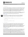
When you blink an LED at 1Hz, you are in fact generating a square wave, albeit a very slow one. The LED
is on for 500ms and off for 500ms. Since the signal is high for half of the time, we call this “50% duty
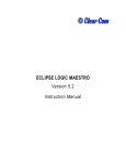
cycle.” Now would be a good time to remind you that the “period” of a wave is the time between
repetitions of the signal and the inverse of period is frequency. Duty cycle is the ratio of the time the
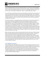
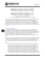
pulse is high to the total period. Figure 10.1.1 shows some details of a 75% duty cycle PWM.
Figure 10.1.1: PWM signal details (75% duty cycle)
If you sped the signal up to 1 kHz, the digital behavior of the LED is exactly the same. The LED is on for
500us and off for 500us. Since LEDs are very fast at reacting to changes in signal voltage, the LED is in
fact going from fully-on to fully-off at the drive rate, which you can verify by attaching an oscilloscope
and looking at the waveform. However, if you are looking at the LED while this is happening, you will
notes_mpgl1_chapter10.docx
Release 1.0
Page 1 of 20
MPG LEVEL 1
not see it blinking because your eye cannot respond that quickly. In fact, your eye can only distinguish
changes at about 10Hz, though you might see some flicker as fast as 30Hz. Instead, you will see the LED
as if it is running at about half the voltage as your supply rail, so it will appear to be half as bright. So a
50% duty cycle – if the frequency is high enough – results in an effective 50% supply voltage.
If you actually measure the effective luminous output it probably is not exactly half, but as a general rule
of thumb, the LED brightness is equal to the duty cycle of the PWM signal driving it. If you change your
driving signal to be on for 250us but off for 750us, the period of the signal remains 1ms, but now you are
running “25% duty cycle” and the LED will appear about one quarter of its full brightness. As long as you
maintain the frequency and just vary the duty cycle (on time vs. off time), then you can make the LED
any brightness that you want.
Not only does this work for varying LED brightness in a digital system, it has many other applications as
well. You have already witnessed PWM in action with the switching power supply on the course
development board. The integrated circuit that converts the high input voltage (7-30V) down to a
regulated 5V uses a fast switch and varying duty cycle to down-convert the higher voltage to the lower
voltage. This is why switching power supplies are much more efficient than linear regulators – power is
only “sampled” as it is needed from the input. If there was no capacitance on the 5V rail, than the
switching frequency of the buck converter (which is a few hundred kHz), would be visible and you would
not have a very good power supply! Switching power supplies require careful calculation of their output
capacitors so that an acceptable amount of “ripple” can be attained (you will always see some evidence
of the switching signal). Generally speaking, the larger the capacitor, the less ripple will be in the system
because the cap stores more energy.
PWM is also used in motor controllers and essentially works the same way to apply an effective voltage
to the motor thereby giving you control over the speed at which the motor is running. This applies in
both AC and DC systems and many microcontrollers have built-in PWM peripherals to target
applications like this. In this way, the PWM signal is essentially pulsing a fly wheel to keep it spinning.
The momentum of the fly wheel is analogous to capacitance in a purely electrical system. If you have a
dimmer switch on some incandescent light bulbs in your home, the same principle applies, but this time
it is the slow reaction and heat build-up of the light bulb that is acting like “capacitance” in the system to
smooth out the PWM action and make it appear as a steady-state lower voltage. As it turns out, the
concept of PWM is everywhere!
10.2 PWM the Hard Way
There is no better way to really understand a concept than to work through an exercise that forces you
to explicitly implement every bit of functionality related to it. So the first PWM exercise we will do is an
upgrade to the LED driver that we have already built for the development board to allow dimming of the
lights via PWM. This will be a great demonstration of what it takes to “bit-bash” some desired
functionality and will give you a bit of an appreciation for the various peripherals that automatically
implement common functions. We have to do this the hard way because the LPC214x processor does
not have enough PWM outputs to drive each LED (it would be very unlikely that you would find a
processor that would have eleven PWMs!).
notes_mpgl1_chapter10.docx
Release 1.0
Page 2 of 20
MPG LEVEL 1
The goal is to create an application that will automatically take care of blinking the LEDs but also provide
a facility to dim the lights by using PWM. Thou
Though
gh dimming of the discrete LEDs will allow for some nice
effects, the main purpose is to havee dimming control for the LCD backlight LEDs. Since the backlight has
red, green and blue lights (denoted
denoted ““RGB” and are the primary colors of light) that light up the screen,
adding them together with different levels of intensity will allow you to form any color you want!
This is exactly how LED displays work – if you look closely, you will see groups of RGB LEDs
LED that are
simply dimmed to a level to create the d
desired color just like mixing paint in art class.. If each color has
256 levels of intensity (in other words, 8bits to control the level), then you can achieve 256 x 256 x 256 =
16.7 million colors! Not that your eye can distinguish that many different co
colors,
lors, but as you have or will
no doubt experience when shopping for monitors or displays, “24bit” or higher color is a major selling
feature that you will pay a bunch of money for (note that no one really knows for sure how many colors
you can resolve and the arguments tend to be more philosophical than logical – opinions have it ranging
anywhere from a few thousand to several million). By the way, if you have equal parts red, green and
blue, the result is white.
10.2.1 Application design
As of Chapter 9, wee have a simple set of function calls living in the board
board-specific
specific source file deva7deva7
ehdw-01.
01. We want to write a reasonably generic LED driver that could be ported to other systems.
LEDs tend to be very board-specific
specific as far as their individual pin conn
connections
ections to the processor, so the
driver we develop will need to account for that and be flexible.. Once the definitions are in place, the
code required to turn the LEDs on and off is quite generic. The complexity of what we want to achieve
provides reasonable
nable justification to pull that code out of the generic file and into its own application
files. The names of the files will be leds2.c and leds_deva7.h.
If you have not downloaded the “start” code for this chapter yet, do that now and load up the project
pro
in
IAR. The code will not build yet because there are several places where you will have to finish the code
snippets. For now, spend a few minutes getting familiar with the code, namely the new files specific to
the LED application and the Chapter 110 exercise.
The biggest problem of bit-bashing
bashing is the overhead required to program each part of the function. This
becomes increasingly difficult as the speed of whatever signal you are trying to create increases, or as
the complexity of the waveform tha
thatt you are trying to create goes up. For example, bit bashing a
communication protocol that transmits and receives at MHz speeds is very challenging if the processor is
running at only 12MHz. In this case, you might be stuck writing assembler routines to get a very
efficient algorithm, and even then you might not be able to do it!
In designing the LED PWM driver, we have to consider the resources that are available and the system
rules we can work with. Ideally we should take advantage of the known 1ms period of our application
calls. It so happens that this will work quite nicely, though it is not perfect because we will come very
close to the limit of what we can do given the speed of the core system. The defining factor is the PWM
capability of the LEDs. As discussed earlier in the chapter, the frequency of the PWM driving signal for
an LED must be fast enough to trick your eye into seeing a steady, dimmed LED instead of a flickering
light. The minimum frequency for this is around 30Hz which gives a period of 33.3ms. Keep that in
mind.
notes_mpgl1_chapter10.docx
Release 1.0
Page 3 of 20
MPG LEVEL 1
The second thing to consider is how much PWM resolution we need / want in the system. For example,
if you wanted 1% duty cycle control, you would need to have a total PWM period of 100 “units” so that
you could adjust
just the duty cycle in 1 unit increments thereby achieving 1% duty cycle steps. Therefore,
each LED could have 100 levels of brightness and you could have 1003 = 1 million different colors. The
problem is that we need 100 cycles available to manage that amount of resolution but of course we only
have 1ms periods/cycles to work with. That would mean we could only achieve 10Hz frequency for the
LEDs and guaranteed you would see them flicker.
“clock”
lock” so we can get better resolution,
So we have to compromise. Either we move away from our 1ms “c
or we admit that wee really do not need a million backlight colors! If higher resolution was really
necessary, you would have to either adapt the 1ms system tick, or use another timer to provide a faster
interrupt to dedicate to the PWM. However, higher resolution is NOT necessary, so we proceed with
our 1ms system intact.
To make numbers work out nicely, let us choose to generate the PWM signal at 50Hz which equates to
20ms periods for the PWM. This gives 5% duty ccycle resolution and results in 203 = 8000 colors.
colors That is
plenty, be assured, to create a very nice display as you will see once you have completed the chapter
exercise. Note that we could probably get away with 25Hz and thus 40 cycles to work with, but it is
likely that some people would notice flicker in the slower signal.
With those decisions made, writing the driver is almost easy. Keep in mind that it still requires a lot of
thought, and though you may read the following description in a few minut
minutes
es and agree that it is in fact
pretty simple, know that designing, coding, testing and tweaking this driver took about 20 hours to
complete when all was said and done
done.
We do not have to build a state machine for the LED system because a single function to manage timers
and perform updates is all that is needed. The function will be called LedUpdate() and will address each
LED explicitly. LedOn(), LedOff() and LedToggle() become private functions to the LED driver.
LedUpdate() will use the private fun
functions
ctions and manage timers to turn the lights on and off. All of the
code is captured in specific LED source files.
10.2.1 Header file leds_deva7.h
A header file is used for the board-specific
specific parameters for the LED driver. The key information is how
many LEDs there are in the system and the names that will be used to identify each LED.
LED Using an
enumerated type for the LED names helps to make the API easier to use. LedNumberType takes care of
this and hopefully it is obvious what LED each word correspond
correspondss to. Other typedefs are used to keep
track of the LED mode, location (i.e. port number) and current duty cycle that you will see are necessary
for running the driver. The code is shown here – you need to add typedef for LedPWMDutyType.
LedPWMDutyType
#define TOTAL_LEDS
#define LED_PWM_PERIOD
(u8)11
(u8)20
typedef enum {WHITE = 0, PURPLE, BLUE, CYAN,
, GREEN, YELLOW, ORANGE, RED, RGB_RED,
RGB_GREEN, RGB_BLUE} LedNumberType;
typedef enum {NORMAL = 0, PWM} LedModeType;
typedef enum {PORT0 = 0, PORT1 = 0x08} LedPortType;
/* $$$$ Add a typedef enum called LedPWMDutyType, where "LOW" = 0 and "HIGH" = 1 */
notes_mpgl1_chapter10.docx
Release 1.0
Page 4 of 20
MPG LEVEL 1
Since the behavior of every LED is independent from the rest, eeach LED will need to have a set of data to
keep track of its specific settingss (i.e. is it blinking or in PWM mode and what rate is it currently set at).
at)
To manage the PWM function, every LED will need a counter variable. All of the parameters will be kept
in a struct whose typedef is also in the LED header file.
typedef struct
{
LedModeType eMode;
LedRateType eRate;
u16 u16Count;
LedPWMDutyType eCurrentDuty;
DeviceActiveType eActiveState;
LedPortType ePort;
} LedConfigType;
Since the board-specific
specific values are kept in the header file, the source file can be almost entirely generic
and “just work” as long as the correct header file is used. That is true at least within the LPC214x family
of processors on any development board. If ported to a different processor, then some updates would
likely be required.
10.2.2 Source file leds2.c
The LED driver source file has some board
board-specific
specific Local Globals, though they are easily adjustable and
will have the same format regardless of where the code is ported too
too. The first is an array of values that
define the bit numbers forr each LED (i.e. their GPIO bit positions).. There is a note in the code to remind
the programmer that the order of the bit positions in the array must correspond to the order of the LEDs
defined in LedNumberType in the header file. It is up to you to add the 11 pin definitions to correctly
define the array. The exact names of the pins from the schematics should be used, and these symbols
have already been defined for this specific development board in deva7
deva7-ehdw-01.h.
/* LED locations: order must corre
correspond
spond to the order set in LedNumberType in the
header file. */
u32 LGau32LedBitPositions[] = {Add the pin location constants
onstants to define this array};
The second local global variable needed keeps track of th
the parameters for each LED. To be able to write
the code to easily accommodate different development boards with different numbers of LEDs, all of
the parameter structs for each LED are kept in an array. The size of this array depends on the constant
TOTAL_LEDS
DS defined in the header fi
file.
le. The code is then written to loop through the whole array
addressing each LED one at a time. The last four definitions are left for you do to.
/* Control array for all LEDs in system initialized for LedInit() */
LedConfigType LGasLeds[TOTAL_LEDS] =
{ {PWM, LED_PWM_100, 0, HIGH, ACTIVE_HIGH, PORT0}, /* White */
{PWM, LED_PWM_100, 0, HIGH, ACTIVE_HIGH, PORT0}, /* Purple */
{PWM, LED_PWM_100, 0, HIGH, ACTIVE_HIGH, PORT1}, /* Blue
*/
{PWM, LED_PWM_100, 0, HI
HIGH, ACTIVE_HIGH, PORT1}, /* Cyan
*/
{PWM, LED_PWM_100, 0, HIGH, ACTIVE_HIGH, PORT1}, /* Green */
{PWM, LED_PWM_100, 0, HIGH, ACTIVE_HIGH, PORT1}, /* Yellow */
notes_mpgl1_chapter10.docx
Release 1.0
Page 5 of 20
MPG LEVEL 1
{PWM, LED_PWM_100, 0, HIGH, ACTIVE_HIGH, PORT1}, /* Orange */
/* Add the remaining 4 definitions */
};
You can see that every LED struct is initialized on startup. By default the LEDs are all on as part of the
LED application startup routine. Only the RGB red LED is active low, and the port number for every LED
is captured as well. So everything we need to access and manage every LED is contained in this array.
We will look through each of the functions in the source file now to go over how they came to be,
starting with the ones that you are already familiar with.
10.2.2.1 LedOn(), LedOff() and Led Toggle()
We wrote functions in Chapter 9 to handle the simple tasks of turning LEDs on or off. Since we were
only working with the discrete LEDs that are all active high, it was not necessary to account for active
low LEDs – but that is not very generic and one of the LCD backlight LEDs is active low so the function
must be updated.
The old function from Chapter 9 looked like this:
void LedOn(LedNumberType eLed_)
{
/* Set pu32SetAddress to the correct FIOxSET register address */
u32 *pu32SetAddress = (u32*)(&FIO0SET + LGasLeds[eLed_]);
/* Set the bit corresponding to the LED of interest by writing to the pointer */
*pu32SetAddress = LGau32LedBitPositions[(u8)eLed_];
} /* end LedOn() */
The “trick” to this function was that pu32SetAddress was loaded with the address of the FIOxSET
register for the correct port in which the LED lives. The array LGasLeds only contained the offset
constant PORT0 or PORT1 that would make this adjustment based on the LED of interest. Once the
address was set, the correct bit was indexed to turn the LED on.
The updated function has two main differences and looks like this:
void LedOn(LedNumberType eLed_)
{
u32 *pu32SetAddress
= (u32*)(&FIO0SET + LGasLeds[eLed_].ePort);
u32 *pu32ClearAddress = (u32*)(&FIO0CLR + LGasLeds[eLed_].ePort);
/* Check for active high or active low */
if(LGasLeds[eLed_].eActiveState)
{
/* Set the bit corresponding to eLed_ if active high */
*pu32SetAddress = LGau32LedBitPositions[(u8)eLed_];
}
else
{
/* Clear the bit corresponding to eLed_ if active low */
notes_mpgl1_chapter10.docx
Release 1.0
Page 6 of 20
MPG LEVEL 1
*pu32ClearAddress = LGau32LedBitPositions[(u8)eLed_];
}
} /* end LedOn() */
Can you spot the changes? Better yet, are the changes that you see immediately obvious as to why they
are necessary? The most significant change is that the function now handles active low and active high
LEDs. The other difference is that the specific LED information like what port it is on and if it is active
high or active low is now in an array of structs that was introduced already. So the eLed_ function
parameter now indexes the LED data array and we have to select the field in the indexed struct to get
the data we want, namely LGasLeds[eLed_].ePort and LGasLeds[eLed_].eActiveState.
The exact same updates are necessary fo
forr LedOff(). You might notice that LedToggle() is almost identical
to the Chapter 9 code since you do not have to care about the active state of an LED when you are
toggling it. So the only change is to properly index the LED parameter array.
10.2.2.2 LedSet()
The first new function of the LED driver is called LedSet() and is responsible for updating certain
parameters that define an LED’s current behavior. There are two lines of code for you to add.
void LedSet(LedNumberType eLed_, LedModeType eMode_, LedRateType eRate_)
{
LGasLeds[(u8)eLed_].eMode
= eMode_;
/* $$$$ Add two lines of co
code to update eRate and u16Count (both set to eRate_) */
if(eMode_ == PWM)
{
LGasLeds[(u8)eLed_].eCurrentDuty = HIGH;
}
} /* end LedSet() */
We use a function like this to abstract the details of how the LED data is stored and provide a single
“entry point” into the LED driver for a user to use. LedSet() becomes the one and only public API
function for the system and should be the only function you ever use to access the LEDs in other
applications that you write. Yes, there is added complexity for the user to use LedSet() in lieu of LedOn()
and LedOff() if they only want to toggle an LED now and then. However, the simplicity of blinking or
PWMing an LED thanks to LedSet() far outweighs the minor overhead of using the same function to
simply toggle it now and then.
10.2.2.3 LedUpdate()
The function that puts everything together and actually updates the LEDs is called LedUpdate(). A call to
this function should appear in the main super loop
loop,, and we consider it “protected” since the usage is
very specific. The function expects to run every 1ms and is thus coded based on that assumption.
assumption If it
does not run every 1ms, then the PWM bit
bit-bashing it is doing will not work properly.
LedUpdate() is a fairly long function and takes a few hundred instruction cycles to process all the LEDs.
It is written in a way that tries to operate as quickly as possible as it works through all of the LEDs on the
board.. For any given LED, the fastest states are ON and OFF, so LedUpdate() ttakes
akes care of those
th
checks
notes_mpgl1_chapter10.docx
Release 1.0
Page 7 of 20
MPG LEVEL 1
first. OFF is the first check because that is most likely the state of an LED at any given time in the
system. The blinking and PWM states are checked las
lastt as those state require further tests based on the
counters that are tracking a change of state. As soon as the current state is found, the other states do
not have to be checked.
ON and OFF functionality should be trivial. If an LED is off, the eRat
eRate
e parameter will be either LED_OFF
or LED_PWM_0. If so, a call to LedOff ensures that it is off. Making this call every time LedUpdate()
LedUp
is
called might not be the best idea because if an LED is already off, then why turn it off again? However,
to check the current state and make a decision about whether or not you need to call LedOff() would
probably take more code and instruction cycles than just calling it every time, thus that is how the code
is written.
/* If LED_OFF, make sure it's off */
if( (LGasLeds[i].eRate
GasLeds[i].eRate == LED_OFF) || (LGasLeds[i].eRate == LED_PWM_0) )
{
LedOff( (LedNumberType)i );
}
/* $$$$ If LED_ON, make sure it's on */
else if ( () || () )
{
/* Turn the LED on */
}
Indexing on the current loop counters lets you generically m
make
ake changes to each LED with a single line of
code. Since the loop index
dex is an unsigned integer, it must be type casted to the enumerated type
LedNumberType or else the compiler will generate a warning. Note that type casting enums to ints or
visa-versa is not an ideal programming practice, so you must be careful on how the enums are set up so
that it works with what you plan to do
do,, especially in cases like this where a loop index is assumed to
traverse the elements of an enum.
The ON check and action is left for you do. This exists as an “else if” because we do not want to run the
code if we have already determined that the LED is off. Ditto for the subsequent check that manages a
blinking or PWMing LED. Modulation code requires a bit more work, and it is slightly different for the
case of just blinking the LED and the case of managing PWM since blinking is an adjustment of frequency
and PWM is an adjustment of duty cycle.
/* Otherwise LED is being modulated in some way */
else
{
/* LED is in normal mode */
if(LGasLeds[i].eMode == NORMAL)
{
/* Decrement counter; toggle and reload if counter reaches 0 */
if( --LGasLeds[i].u16Count
LGasLeds[i].u16Count == 0)
{
LedToggle( (LedNumberType)i );
LGasLeds[i].u16Count = LGasLeds[i].eRate;
}
notes_mpgl1_chapter10.docx
Release 1.0
Page 8 of 20
MPG LEVEL 1
}
/* LED is in PWM mode */
else
{
/* Decrement counter; toggle and reload if counter reaches 0 */
if( --LGasLeds[i].u16Count
LGasLeds[i].u16Count == 0)
{
if(LGasLeds[i].eCurrentDuty == HIGH)
{
LGasLeds[i].u16Count = LED_PWM_PERIOD - LGasLeds[i].eRate;
LGasLeds[i].eCurrentDuty = LOW;
LedOff( (LedNumberType)i );
}
else
{
LGasLeds[i].u16Count = LGasLeds[i].eRate;
LGasLeds[i].eCurrentDuty = HIGH;
LedOn( (LedNumberType)i );
}
}
} /* end LED PWM mode */
} /* end LED modulated */
The source code in the leds2.c file is missing the “normal” mode code that is shown above. For a bit of a
challenge you can try to figure it out yourself, or if you want to move on then simply copy the code
above.
10.2.2.4 LedInit()
LedInit() is discussed last here as it turns out to be the most complicated and relies on LedUpdate(). As
you should know by now, every application that is added to the system will need an initialization
function to properly set it up before the main program super loop starts to run. There are no timing
rules during initialization, but also no 1ms calls to the function that you can make use of.
of Initialization
functions run once, and are permitted to take as long as necessary (th
(though
ough they should never fail to exit
if something does not work and should do everything possible to not crash the system
system).
). Even though
the automatic 1ms timing is not available, tthe system tick timers are in fact running by the time LedInit()
is called so you can still make use of them for timing purposes. To use them, use the IsTimeUp() utility
function.
The init function for the LED system does not really need to do very much beyond putting the LEDs in a
state that makes sense for the main program to start running (likely this would be all OFF).
OFF) However, as
a means to self test all of the LEDs (the user is responsible for verifying that they all light up),
up make
things a bit interesting, and demonstrate the operation of the LED driver, a little display
displa sequence will be
shown. The plan is to turn on all of the LEDs at full intensity,, and then fade them out over a few
seconds. Wee want to use our LedUpdate() function during this initialization so we do not have to waste
time writing different code, however
ver we do not yet have the super loop 1ms system running so we have
to work around that. The structure of LedInit() is as follows:
notes_mpgl1_chapter10.docx
Release 1.0
Page 9 of 20
MPG LEVEL 1
Loop
oop to progress through the 20 available duty cycles
{
Nested loop
oop to wait 40ms at the current intensity
{
Delay 1ms using IsTimeUp()
Call LedUpdate()
}
Wait additional 1.5 seconds at full intensity only
Use a loop to update
pdate the PWM duty cycle of all of the LEDs to the next lowest level
}
Final call to LedUpdate() since LEDs will be off
Short delay to complete
omplete the display
The nested loop that runs 40 times performs the action of the 1ms super loop. LedUpdate() must be
called every 1ms to properly implement the PWM functionality that it provides. 40ms x 20 different
PWM levels makes the LEDs fade out over about 800ms which, by test, looks the best. If you try to slow
it down, then the 5% duty cycle steps start to become more obvious. To make the fade out look smooth
when the duty cycle is changed,, it is important to make the duty cycle change only at the end of a
period. In other words, the delay loop choices are limited to 20ms, 40ms, 60ms, etc.
Updating the LEDs for the next cycle uses a loop to run through all the LED arrays. Again, the loop
indexes must be typecast to their respective enum types or else the compiler will send up warnings.
/* Set the intensity for the next iteration */
for(u8 j = 0; j < TOTAL_LEDS; j++)
{
LedSet( (LedNumberType)j, PWM, (LedRateType)(i - 1) );
}
There are two special cases within LedInit(
LedInit()) where extra delay is added to stretch out some time periods
at the beginning and at the end. The choice of these time periods is almost entirely arbitrary – they just
look right.
That completes the LED driver. The code should now build so you can see the fruits of your labor. Even
if you did not understand
nderstand all of the code to implement the LED driver, the good news is that all you need
to know to use the LEDs from this point on is the single API function LedSet().
10.3 PWM the Easy Way - LPC214x PWM Peripheral
As you just saw, bit-bashing
bashing PWMs is not that difficult, though does require a certain amount of
processor resources to monitor timing and adjust duty cycles. It is functionality that begs for a
peripheral to take care of automatically. PWM is such a fundamental capability of an embedded system,
sy
you can almost guarantee that any microcontroller or microprocessor you choose will have at least one
PWM peripheral capable of running at least a few PWM channels.
Regardless of the processor you are using, a PW
PWM peripheral is pretty much just a timer
mer peripheral with
a few extra features (and in some cases, less features than a timer
imer peripheral). The most notable
difference between the two is that a PWM peripheral can be set up so that different events can occur at
notes_mpgl1_chapter10.docx
Release 1.0
Page 10 of 20
MPG LEVEL 1
different times in the waveform generation
eneration period and thus allows for varying duty cycles,
cycles whereas
timers usually only have one event per period
period. On some processors, PWM functionality is built in to all
timer peripherals rather than having discrete PWM
PWMs and timers.
pheral on the LPC214x processor is straight forward. Just like you did with the Timer
Using the PWM peripheral
and GPIO peripherals, you need to examine the datasheet to determine what registers are required to
get the peripheral running the way you want. Open up the LPC214x Userr Manual and to Chapter 16 that
covers the PWM peripheral. The description of the module indicates that the clock source is PCLK
which, if you refer back to discussions about clock scaling, you know is 1:1 to the main system clock of
12MHz. There is mention about single edge and double edge control that is rightfully confusing, but also
talk about match registers that should make sense even though you do not yet know how everything is
implemented.
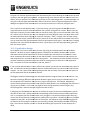
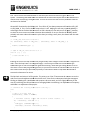
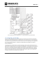
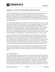
If you look at the block diagram that is copied and shown here in Figure 10.3.1,, you might feel a bit
overwhelmed about the complexity of the PWM peripheral. But fear not, it is actually quite
straightforward to set up and use! Part of the complexity comes from the fact that there are 6 PWM
generators (channels) within the peripheral which add a lot to the diagram to make it look so
complicated. But really there are just six copies of the same PWM architecture,, so if you figure one out,
then the system unravels itself.. You can spend some time tracing through the diagram to make sense of
what is going on for one of the channels
channels,, or you trust that it works and skip that for now. Unless you are
doing some low-level
level hacking or tweaking, it is unlikely you would devote any effort to deciphering the
internals of a peripheral.
If you need PWM outputs in a design, make sure you correctly assign the hardware that requires PWM to
a pin where PWM output is available. Also check that there are no conflicts with the PWM peripheral
output for the pin you have chosen.
sen.
notes_mpgl1_chapter10.docx
Release 1.0
Page 11 of 20
MPG LEVEL 1
Figure 10.3.1: PWM peripheral controller hardware
Source: LPC214x User manual, UM10139, Rev. 3 – 4 October 2010, p.259. NXP Semiconductors
10.3.1 Single Edge / Double Edge
Single and double edge PWM signals determine how many transitions you will actively manage with
match registers when defining the signal. All PWM signals in this peripheral share a common end point
at the end of one cycle period where a transition may or may not occur depending on the configuration.
Even if nothing explicitly happens, it is important to understand that this endpoint is the end of a
particular PWM period.
Single edge behavior allows firmware to specify a single high-to-low transition and leaves the low-tohigh transition to automatically occur at the end of the PWM period. The assumption is that the signal is
high at time = 0 and will go low when the PWM’s counter equals the match register value. Once the
timer reaches the maximum value of the PWM period, the signal transitions back to high. Single edge
PWMs can be kept high (100% duty cycle) by setting the match register larger than the PWM period.
The signal can be kept low by setting the match register to 0.
notes_mpgl1_chapter10.docx
Release 1.0
Page 12 of 20
MPG LEVEL 1
With double edge signals, it is expected that two transitions will be specified in firmware, thus there will
be two transitions inside of the total period defined by the user. This allows several PWMs within the
peripheral to use the same period but select a time within the total period where the signal is high or
low. This is useful in certain motor control applications or any application in general where the PWMs
must be carefully synchronized. For example, three phases in a motor may require a 33% duty cycle for
each phase, but never at the same time. Therefore you could define the PWM period as 99 with three
double-edge PWM channels set to be high for periods 1-33, 34-66 and 67-99. Since they run from the
same PWM peripheral, exact synchronization is ensure which will be appreciated by your customer
when their motor does not blow apart.
The rules for single edge and double edge PWM outputs are clearly listed in the processor user guide. If
you were designing a system that relied on correct operation of the PWM outputs, setting the processor
up and watching all the channels on an oscilloscope would be a good step to perform during the design
phase.
10.3.2 PWM Registers
The registers needed to configure the PWM module are shown in Table 248 of the user manual. Though
it looks like there are quite a few, six of them are just match registers that do the same thing for
different channels and the others are setup registers, some of which we will use and some we can
ignore. Do not forget to turn on the power and clock source to the peripheral in the PCONP register.
Each of the PWM registers is detailed here. The information about the purpose of each register is
almost verbatim from the user manual, though a few clarifications are made. As an engineer, you will
be responsible for using the data sheet to fully understand the peripheral you are working with. You
have to determine how the peripheral works (in general) and then what registers are relevant to your
application. In most cases, choosing the register setup values is straightforward, though occasionally
you will come across some options that do not make immediate sense, in which case you will have to try
them out and see if the behavior is what you want. Some processor documentation does an excellent
job and explaining everything, others seem to leave out important information that you have to find
elsewhere or figure out through trial and error.
PWMIR: Interrupt flag register that will be ignored as PWM interrupts are not required.
PWMTCR: Timer Control Register providing the core on/off and reset control of the peripheral.
PWMTC: Timer Counter register that holds the current value of the timer for the PWM peripheral. You
do not typically use this register, though you need to be aware of its significance with respect to the
behavior of the PWM peripheral.
PWMPR: Prescale register that is optionally used to slow down the clock source to the peripheral.
Prescale registers are clock dividers and while most use bit-wise setting to apply fixed scaling ratios (like
1:2, 1:8, etc.), this peripheral uses an entire counter to count up to a value before the main timer
increments. This register is the value to which the prescale counter counts before the main peripheral
clock increments (and the prescale counter resets and repeats). Set to 0 for no prescale.
PWMPC: The prescale counter register.
PWMMCR: Match control register for configuring what event occurs for each channel of the PWM when
the main counter value reaches the value in a specific match register. For each of the six channels, you
can choose to have an interrupt, reset the timer, or stop the timer.
notes_mpgl1_chapter10.docx
Release 1.0
Page 13 of 20
MPG LEVEL 1
PWMMR0:: Match Register 0 is the main match register that is used to set the PWM period. All match
registers are static valuess that are typically set once for a given PWM signal. The value is compared
against the current PWM counter value (PWMTC) with every clock tick. When PWMTC has incremented
enough to match the value of PWMMR0, then the corresponding event configured in PWMMCR[2:0]
PW
takes place. If this register is set to 0, then the PWM signal is never asserted high (0% duty cycle).
PWMMRx:: The remaining Match Registers specify actions of the six PWM channels. For single edge
PWM signals, the value in the corresponding ma
match
tch register is the count at which the PWM output will
go from high to low. For double edge PWMs, two match registers are required to define the signal
behavior. Generally speaking, the value of PWMMRx (1 <= x <= 6) register is always less than the value
in PWMMR0. If it is greater, then that particular channel will never transition low when in single edge
mode (100% duty cycle).
PWMPCR:: PWM Control Register to configure and activate each of the PWM channels. This is where
single or double edge mode is selected (1 bit per channel) and individual channels can be enabled or
disabled with another bit per channel.
PWMLER:: Latch Enable Register is a control mechanism to help synchronize updates to the PWM
peripheral. If you change the duty cycle of one or mo
more
re PWM channels by changing the respective
PWMMRx register, the change does not actually take effect until a bit in PWMPCR is set corresponding
to the channel that is updated. This allows you to update several match registers without impacting the
current duty cycles, and then simultaneously applying the changes so that all channels adjust at the
same time. This would be extremely important in applications where duty cycle changes are frequent
and, to cite the motor control example again, are critical in timing and synchronization so you do not
blow things apart.
Configuration of these registers specific to the course development board is described in the next
section since all settings are highly application
application-specific.
10.4 Development Board Audio Driver
Now that you know how to setup the PWM peripheral, we can introduce the application to which it will
be applied – audio. Generating a square wave to drive a beeper / buzzer is a great way to take
advantage of a microcontroller’s PWM peripheral, even though use of the peripheral in this way is not
the way it really is intended to be used
used. PWM is supposed to adjust duty cycle to achieve different
results, but using the PWM for audio will keep a 50% duty cycle and just change the frequency.
As a side note, piezoelectric (pronounced pee
pee-EH-zoh-electric)
electric) buzzers like the one that is on the course
development board respond very nicely to a square
square-wave
wave drive and they can usually be driven directly
from the processor
cessor pin as they are voltage
voltage-actuated devices
vices and barely draw any current. You cannot
drive a magnetic coil speaker directly from a processor because they rely principally on current and have
very little DC resistance. A speaker coil requires tens if not hundreds of milliamps of drive current which
a processor cannot source directly (at the extreme case, a big sub woofer could pull tens of amps of
current).
Regardless of the type of speaker/buzzer you have, never leave a DC voltage applied to it. If you are not
driving the speaker, the output
ut pin to the speaker should be at 0 volts.
notes_mpgl1_chapter10.docx
Release 1.0
Page 14 of 20
MPG LEVEL 1
What we would like to have out of all of this is an easy way to use the PWM peripheral to send a tone
signal to the piezoelectric buzzer on the development board. To do this, we need to setup the PWM
peripheral and write a few API functions to allow any application in the system to use audio easily. The
goal is to write a simple interface where the tone frequency can be specified and turned on and off. We
do not need to write this as an application since the PWM peripheral pretty much takes care of all the
work. An application might be necessary if you wanted to expand the audio capability to play music, or
allow priority access to the buzzer.
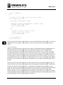
10.4.1 PWM Hardware
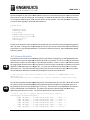
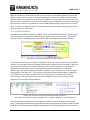
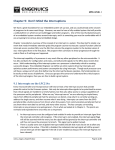
The PWM channel used for the buzzer is PWM5. Do you know how to determine this? Figure 10.4.1.1
shows the section of the schematic where the buzzer signal connects to the processor. This pin was
selected carefully in the design phase of the PCB to make sure the PWM resource was available.
Figure 10.4.1.1: Schematic showing buzzer signal connection
Since the function of this pin is assigned to a peripheral, you have to make sure that the relevant GPIO
registers are set to take the pin out of standard GPIO mode and connect it to the peripheral. While this
has already been in place in the code since Chapter 8, this is the first time we are using peripheral
functionality that depends on it so it is a good place to draw some attention to it. Look at the
PINSEL1_INIT value in deva7-ehdw-01.h for P0.21_BUZZER – you can see that it is not “00” like all the
GPIO digital pins, but rather “01.” If you check the Table 38 Pin function Select register 1 (PINSEL1) in
the user guide, you see where this comes from. No mysteries here, just awareness on how the
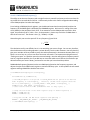
processor works and how to find and use the relative information. Figure 10.4.2 shows relevant
snippets of the user guide and the header file.
Figure 4.10.2: P0.21 user manual (left) and firmware (right) information
Table 38 Source: LPC214x User manual, UM10139, Rev. 3 – 4 October 2010, p.61. NXP Semiconductors
You must also make sure that the pin is configured as an output since the peripheral is outputting a
signal. Configuring a data direction register based on what the peripheral connected to it does is usually
a safe bet, but you should always read the datasheet to be sure. Some peripherals will have their own
notes_mpgl1_chapter10.docx
Release 1.0
Page 15 of 20
MPG LEVEL 1
output drivers separate from the GPIO driver and require the GPIO data direction register to be set a
certain way for the peripheral outp
output to work. You should never have to guess at this – the information
should be somewhere in the user manual, although occasionally it is hidden quite well...
well..
NEVER guess at choices you make as an engineer. Read documentation to find the answer you need. If
you cannot find the answer, find someone who knows. If you have to figure something out because it is
a brand new problem, use a systematic process in a controlled eenvironment and try to use as much
reliable information as possible to limit the amount of guesswork/experimentation you do.
do
10.4.2 PWM Firmware
The firmware functionality we need to make all of this work is captured in 4 functions that will be
written in the deva7-ehdw-01
01 source files since they are quite board
board-specific:
•
•
•
•
void PWMSetupAudio(void) – initialize the PWM peripheral for the specific use of buzzer audio
void PWMAudioSetFrequency(u16 u16Frequency_) – configure the PWM peripheral for the
desired audio frequency.
void PWMAudioOn(void) – activate the PWM peripheral.
void PWMAudioOff(void) – deactivate the PWM peripheral (i.e. turn buzzer off and leave the
line low)
10.4.2.1 PWMSetupAudio()
The PWM peripheral registers that are required for the audio application are all set up in this function
which is called during board initialization as part of the existing DEVA7RazorSetup() function.
function Open
deva7-ehdw-01.c
01.c and find the function to see what registers require configuration. Note that after this
code executes, the peripheral is ready to be used (but the audio output is not yet enabled so the beeper
is quiet).
The course development board has a dip switch to physically disconnect the beeper. Make sure the
switch is on to hear the sound. If you are testing audio functions to see if the waveform you are sending
is correct but you do not want to listen to the beeper, you can turn it off but still measure your audio
signal at the BUZZ test point.
Open the deva7-ehdw-01 header file and find the PWM se
setup
tup values (you can search for a few “^^^”
characters that bookmark the code
code).
). Here you will find the INIT values used in the setup function as well
as some definitions for some update mnemonics.. As usual, all bits are explained which, though it
requires extra effort, lets you immediately see the purpose and value of each bit. The PWMPCR_INIT
value is left for you to
o complete. Make sure you fully document the bits, make the correct binary
assignments in the comments, and then update the hex value that iis actually loaded.
A common mistake to make with header files like this is to update the values of comments without
updating the hex value that is actually used. A good rule of thumb is to delete the hex value for any
setup value you are working with and
nd retype it when you are done with the comments. If you do this
and forget to update the hex value, at least the compiler will catch your mistake because the value it
tries to use is not complete.
notes_mpgl1_chapter10.docx
Release 1.0
Page 16 of 20
MPG LEVEL 1
10.4.2.2 PWMAudioSetFrequency()
The ability to set the tone frequency with a single function is powerful and pretty much a must-have for
any useful API to an audio driver like this. Unfortunately it takes a bit of work and good understanding
of the PWM peripheral to make that happen.
From looking at PWM peripheral registers, you should now know that the total period (and thus the
frequency) of the PWM signal is defined by the PWMMR0 register. We have a 1:1 scaling of the main
clock (12MHz) to the peripheral clock, PCLK. If we wanted to set the PWM period to provide a 1kHz
signal, the period must be 1 / 1kHz = 1ms. So the question is, how many clock ticks at 12MHz does it
take to time out 1ms? The answer is 1ms / (1 / 12MHz) = 12,000.
Generalizing this, we can solve period T for any frequency f given PCLK:
ܶ=
ܲܭܮܥ
݂
The calculation really is not difficult, but it is not something you want to forget. You can see, therefore,
that the discussion and resulting equation is written directly into the code comment. Not only does this
give you a reminder of what you did to justify the code implemented, it documents what was done so if
there is an error later on, you can see where that error was made. The importance and significance of
“finding root cause” to a problem cannot be stressed enough. Not that setting buzzer frequency would
ever be a significant problem, but if you did have an issue and could trace it back to the calculation you
derived because you wrote it down, you know for sure that you have solved the problem.
PWMAudioSetFrequency() determines the new PWM period based on the frequency argument, and
adjusts the value for the MR5 match register to maintain 50% duty cycle. It then updates the two match
registers and flags PWMLER to load the new values.
void PWMAudioSetFrequency(u16 u16Frequency_)
{
u32 u32MR0Period, u32MR5Period;
/* The PWM peripheral clock period is 1/PCLK_VALUE and the period of the desired
audio frequency is 1/u16Frequency_. Therefore, the MR0 match register should be
set at (1/u16Frequency_) / (1/PCLK_VALUE) = PCLK_VALUE / u16Frequency_ */
u32MR0Period = PCLK_VALUE / u16Frequency_;
/* $$$$ Load the value for MR5 (remember we want 50% duty cycle) */
/* Setup the new values in the match register (kept in shadow registers) */
PWMMR0 = u32MR0Period;
PWMMR5 = u32MR5Period;
/* Flag that the MR0 and MR5 match registers need updating */
PWMLER = _PWM_ENABLE_MR0_UPDATE + _PWM_ENABLE_MR5_UPDATE;
} /* end PWMAudioSetFrequency() */
notes_mpgl1_chapter10.docx
Release 1.0
Page 17 of 20
MPG LEVEL 1
10.4.2.3 PWMAudioOn()
The easiest way to turn the PWM peripheral on and off is with the match 5 register – when it is set to
zero, the PWM peripheral will keep the line low. It is assumed that the frequency of the desired PWM
signal is set prior to calling PWMAudioOn(), and all the function does is reset MR5 back to half of the
MR0 register.
10.4.2.4 PWMAudioOff()
On this particular processor, turn the PWM signal off by setting MR5 to 0. The frequency last set in the
peripheral will not be disturbed since the period is kept in MR0. Most importantly, this guarantees that
the pin voltage is low so you do not leave a DC bias on the buzzer. The only problem with this method is
that the PWM peripheral is still on and thus consuming current, even though it is not driving the output.
If you had a low power application, then functions to turn the PWM on and off would need to also
manage the PWM power control bit and make sure the buzzer line was low (which probably means you
would need to change the pin mode back to GPIO so you could set it to zero).
10.4.3 Audio Bits
You now have everything you need for the audio driver and the code should build and be ready for test.
As a last bit of info on the subject, here is a quick music lesson that might come in handy:
1. You should fully understand that different musical notes are a function of frequency. The lower
the frequency, the lower the sound. Deep bass is sub 100Hz; the highest sound a human can
hear is around 16kHz depending on how loud your music was when you were a teenager and
thus how sensitive your ears are still. Dogs can hear much higher frequencies.
2. Different speakers are better at reproducing different frequencies (i.e. subwoofers for bass,
tweeters for very high sound).
3. Music is written with notes from A to G which span one “octave”. There are 8 octaves spanning
note frequencies start at C0 = 16Hz all the way to C8 = 4186Hz. In musical terms, it does not
make much sense to talk about sounds above that frequency, though there is theoretically no
upper limit.
4. In every octave, you have the notes A, A-sharp (B-flat), B, C, C-sharp (D-flat), D, D-sharp (E-flat),
E, F, F-sharp (G-flat), G, G-sharp (A-flat of the next octave). The symbol for “sharp” is # like C#
(not to be confused with the programming language, but no doubt someone thought they were
being clever when they named it) and the symbol for “flat” is b like Ab.
5. The exact frequencies of notes or someone relative, but are mathematically defined based on a
reference value. Check out this link if you want to learn more:
http://www.phy.mtu.edu/~suits/NoteFreqCalcs.html
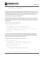
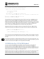
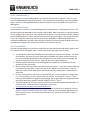
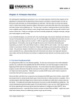
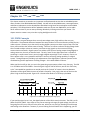
6. Music is written by defining single notes or combinations of notes that are played for a certain
duration. These are shown on a five-line “staff.” There are a lot more details beyond that, but
that is enough for now. An example is the sheet music for “Mary had a little lamb” shown in
Figure 10.4.3.1.
notes_mpgl1_chapter10.docx
Release 1.0
Page 18 of 20
MPG LEVEL 1
Figure 10.4.3.1: Music for “Mary and a little lamb”
Source: http://www.enchantedlearning.com/mu
http://www.enchantedlearning.com/music/sheetmusic/maryhadalittlelamb.shtml
sic/sheetmusic/maryhadalittlelamb.shtml
There are some pretty easy ways to program algorithms that will play simple single
single-note
note songs over a
piezo buzzer. Essentially you write two arrays: one with the sequence of notes, and one with a
corresponding duration
ation to play each of those notes. There are even some standard algorithms for
computer generated music that you could program and then download source files with various songs.
We will not explore that in this course, but if you are interested it would be an easy programming
exercise to explore. Note that there are three octaves of note constants defined in deva7-ehdw-01.h
deva7
for
you to use.
10.5 Chapter Exercise
This chapter has improved the core firmware that is running on the development board by adding
addin a
better LED driver and providing basic audio functionality all with the help of PWM.. You should be
comfortable with the use of the LED API function LedSet() where LedNumber, LedMode and LedRate are
specified to manage each LED. You do not need any oth
other
er functions to work with the LEDs from this
point on! The audio capability of the board is accessed by setting a frequency with
PWMAudioSetFrequency()
() and then using the PWMAudioOn/Off() functions to start and stop the
buzzer.
The chapter exercise is in two parts that test the audio and LED skills separately. Both of these exercises
are entirely C programming tasks like you would receive in a lab, though they are way cooler because
they run on your own development board. You may only write code in the Chapter10 source file.
file You
do not need any additional states. Both tasks must run at the same time when you are complete.
Tasks:
1. Create a 4-note
note synthesizer where the notes G4, A4, B4 and D5 will play when BUTTON0 thru
BUTTON3, respectively, are pressed
pressed.. Prove that your program works by playing “Mary had a
little lamb” (the sheet music is shown above).. It does not have to be absolutely perfect, for
example do not worry about what happens when two buttons are pressed – assume that only
one button will bee pressed at the same time. Hint: every time you call PWMAudioOn, the
current PWM cycle is reset so if you call it repeatedly, you will not get the correct tone.
tone
2. Color cycle the RGB backlight. Write a tight piece of code to color cycle the three RGB LEDS so
they mix together and show off most of the 8000 colors you have available. Though you could
write this fairly brute force, take some time to design a solution that is code efficient. The PWM
notes_mpgl1_chapter10.docx
Release 1.0
Page 19 of 20
MPG LEVEL 1
rates for each LED to cycle through a rainbow of colors in the correct ROYGBIV order should be
as follows:
a. Red LED ramps up from 0 to 100%
b. Green LED ramps up from 0 to 100%
c. Red LED ramps down from 100 to 0%
d. Blue LED ramps up from 0 to 100%
e. Green LED ramps down from 100 to 0%
f. Red LED ramps up from 0 to 100%
g. Blue LED ramps down from 100 to 0%
h. Repeat from b
Do not forget to put the call in to initialize and run the Chapter 10 application in main.c.
If you want a hint, here are the variables from Chapter10SMIdle() that the solution uses to accomplish
the task:
static
static
static
static
static
static
u16 u16Counter = COLOR_CYCLE_TIME;
u8 au8LEDOrder[] = {RGB_RED, RGB_GREEN, RGB_RED, RGB_BLUE, RGB_GREEN, RGB_RED, RGB_BLUE};
u8 au8LEDDirection[] = {0x01,
0x01,
0x00,
0x01,
0x00,
0x01,
0x00};
u8 u8RGBIndex = 0;
u8 u8RGBCurrentLevel = 0;
u8 u8RGBCounter = 0;
Remember that there is probably a ton of different ways to program this solution. The code space
required for this implementation was 316 bytes, determined by building the code with and without the
color cycling code and comparing the size of the chapter10.0 object files. You can see the size of your
code by looking at the .map file for the project and finding the MODULE SUMMARY. Figure10.5.1 shows
a screen shot of the object file size including the cycling code.
Figure 10.5.1: Map file showing chapter10.o object size
Closing thought: You could port this code to a purpose-built PCB and create a very neat night light or
other great lighting effects in your home or car. This is a great example of how the learning you do with
a development board can be applied to a real-life product!
notes_mpgl1_chapter10.docx
Release 1.0
Page 20 of 20