1
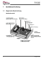
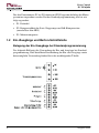
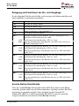
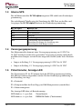
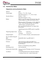
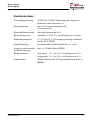
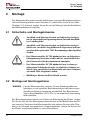
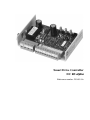
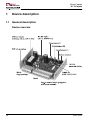
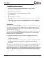
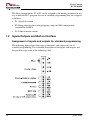
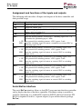
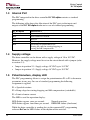
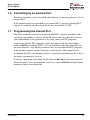
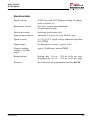
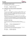
Intelligenter Motorcontroller
DC RS alpha
Bestellnummer: 250 00 81x
Seite 1
Page 21
Drive Control
DC RS alpha
Copyright
Ohne ausdrückliche Genehmigung der bebro electronic GmbH darf kein Teil
dieser Betriebsanleitung für irgendwelche Zwecke vervielfältigt, veröffentlicht
oder übertragen werden, gleichgültig auf welche Art und Weise und mit welchen
Mitteln dies geschieht.
© 1999 bebro electronic Bengel & Broß GmbH. Alle Rechte vorbehalten.
Allgemeiner Hinweis
Technische Änderungen nach Drucklegung werden nicht berücksichtigt.
Änderungen vorbehalten.
Stand: September 1999
Herstelleradresse
Für Informationen, Hilfestellungen bei technischen Problemen, Serviceleistungen
und Bestellungen stehen wir Ihnen gerne zur Verfügung.
bebro electronic Bengel & Broß GmbH
Max-Planck-Straße 6-8
D-72636 Frickenhausen
Telefon
Telefax
+49-(0) 7022-40 03 0
+49-(0) 7022-42 77 2
Besuchen Sie uns auch im Internet unter http://www.bebro.de
2
Ausgabe 09/99
Drive Control
DC RS alpha
Inhaltsverzeichnis
Wichtige Hinweise und Wissenswertes ................................................................ 4
Sicherheitshinweise............................................................................................... 4
Bestimmungsgemäße Verwendung....................................................................... 5
1 Gerätebeschreibung......................................................................................... 6
1.1 Allgemeine Beschreibung........................................................................ 6
1.2 Ein-/Ausgänge und BeCon-Schnittstelle ................................................. 8
1.3 Interne SPS............................................................................................ 10
1.4 Versorgungsspannung ........................................................................... 10
1.5 Potentiometer, Anzeige-LED ................................................................ 10
1.6 Steuerung durch eine externe SPS......................................................... 11
1.7 Programmierung der internen SPS ........................................................ 11
1.8 Technische Daten .................................................................................. 12
2 Montage ........................................................................................................ 14
2.1 Sicherheits- und Montagehinweise........................................................ 14
2.2 Montage auf Normtragschiene .............................................................. 14
2.3 Montage an der Wand ........................................................................... 15
2.4 Anschluß/Verdrahtung .......................................................................... 15
3 Inbetriebnahme und Bedienung..................................................................... 16
3.1 Einstellen des Versorgungsspannungsbereichs...................................... 16
3.2 Betriebsanzeige über LED..................................................................... 16
3.3 Einstellen der Drehzahl ......................................................................... 17
3.4 Einstellen der Rampensteilheit und der IxR-Kompensation.................. 17
3.5 Einstellen der Motorstromgrenze .......................................................... 18
3.6 Motor Linkslauf/Stopp .......................................................................... 18
3.7 Motor Rechtslauf/Stopp ........................................................................ 18
3.8 Motor Schnellstopp ............................................................................... 18
3.9 Motor Freigabe...................................................................................... 19
3.10 Anwendungsspezifische Programmierung............................................. 19
4 Wartung......................................................................................................... 20
5 Außerbetriebnahme und Entsorgung............................................................. 20
6 Transport und Lagerung ................................................................................ 20
7 Zubehör ......................................................................................................... 20
Ausgabe 09/99
3
Drive Control
DC RS alpha
Wichtige Hinweise und Wissenswertes
Sehr geehrter Kunde,
Sie haben sich mit dem Motorcontroller DC RS alpha für ein technisch hochwertiges Produkt entschieden. Bei der Herstellung dieses Gerätes wurden ausschließlich hochwertige Bauteile verwendet, die den Anforderungen der VDEPrüfungen sowie den DIN- und Europanormen entsprechen.
Alle Informationen in dieser Betriebsanleitung wurden sorgfältig nach bestem
Wissen und Gewissen zusammengestellt und geprüft. Bitte lesen Sie vor Einbau
und Inbetriebnahme des Gerätes die Betriebsanleitung aufmerksam durch.
Die Firma bebro electronic GmbH übernimmt keinerlei Haftung für die Anwendung sowie für Schäden, die aufgrund falscher Bedienung und Handhabung,
Mißbrauch, unerlaubten technischen Änderungen oder aufgrund von Reparaturen
durch nicht autorisiertes Personal verursacht wurden.
Sollten Sie Fragen haben, wenden Sie sich bitte an Ihren Händler oder direkt an
bebro electronic GmbH.
Sicherheitshinweise
Lesen Sie die folgenden Sicherheitshinweise sorgfältig und beachten Sie diese
entsprechend. Dies ist Voraussetzung für einen sicheren Einsatz der Elektronik.
• Anschluß- und Montagearbeiten an elektrischen Anlagen
nur in abgeschaltetem spannungslosem Zustand durchführen. Lebensgefahr!
VORSICHT
• Anschluß- und Montagearbeiten an elektrischen Anlagen
dürfen nur von dafür ausgebildetem Fachpersonal und entsprechend den geltenden VDE-Bestimmungen durchgeführt
werden.
• Das Gerät ist zum Einbau in eine Maschine bestimmt. Die
Inbetriebnahme ist so lange untersagt, bis festgestellt wurde,
daß die gesamte Anlage den Bestimmungen der anwendbaren EG-Richtlinien entspricht.
ACHTUNG
• Angeschlossene Maschinen und Anlagen müssen mit eigenen, vom Motorcontroller DC RS alpha unabhängigen
Überwachungs- und Sicherheitseinrichtungen versehen sein.
4
Ausgabe 09/99
Drive Control
DC RS alpha
• Der Motorcontroller DC RS alpha darf nur an Sicherheitskleinspannung betrieben werden und ist ausschließlich für
den Einsatz mit Gleichstrommotoren konzipiert.
• Kühlkörper können im Betrieb heiß werden.
• Die Steuerung ist extern mit geeigneten Sicherungselementen abzusichern.
Bestimmungsgemäße Verwendung
Der Motorcontroller DC RS alpha ist eine frei programmierbare elektronische
Steuerung für Gleichstrommotoren. Über diesen Controller können Start und
Stopp des Motors, Drehrichtung und Drehzahl sowie der maximal zulässige Motorstrom vorgegeben werden. Außerdem können Rampensteilheit und IxRKompensation eingestellt werden. Bitte beachten Sie auch die Anleitungen im
BeCon-Benutzerhandbuch.
Der Motorcontroller DC RS alpha darf nur für die hier angegebenen Anwendungen und nur entsprechend den Angaben in dieser Betriebsanleitung benutzt
werden. Er ist für den Verkauf an kommerzielle industrielle Anwender und nur
für die Benutzung durch diese bestimmt.
Bei unsachgemäßer oder mißbräuchlicher Verwendung des Gerätes übernimmt
die bebro electronic GmbH keinerlei Haftung.
Ausgabe 09/99
5
Drive Control
DC RS alpha
1
Gerätebeschreibung
1.1 Allgemeine Beschreibung
Geräteübersicht
6
Ausgabe 09/99
Drive Control
DC RS alpha
Die wichtigsten Merkmale im Überblick
• Intelligenter Motorcontroller mit integrierter Klein-SPS für Gleichstrommotoren
• Dauer-Motorstrom 5 A
• Maximaler Motorstrom 10 A
• 5 Digital-Eingänge, davon 1 schneller Zähleingang bis 1 kHz
• 3 Potentiometer
• Rampenfunktion bei Start/Stopp
• Vorprogrammiert für Standardfunktionen Stopp, Links, Rechts, Schnellstopp
• Anwendungsspezifische Anpassung der Software-Funktionen mit BeCon
möglich (AWL angelehnt an IEC 1131)
Beschreibung
Der Motorcontroller DC RS alpha ist auf einer Platine ohne Schutzgehäuse untergebracht. Die Platine kann entweder mit Hilfe von vier Befestigungsbohrungen
direkt auf entsprechenden Abstandhaltern oder mit einem separaten Hutschienenadapter (Bestellnummer 250 01 37x) auf einer Normtragschiene montiert werden.
Der Motorcontroller DC RS alpha eignet sich zur Steuerung von Gleichstrommotoren. Er enthält eine frei programmierbare Klein-SPS mit fünf Eingängen.
Die Steuerung der Eingänge ist auch durch eine externe SPS möglich.
Die 5 Eingänge können wie folgt verwendet werden (alle 5 Eingänge können
auch mit +24 V angesteuert werden):
• 4 Eingänge zum Anschluß von potentialfreien Kontakten (z.B. für Taster,
Endschalter, Lichtschranken).
• 1 Eingang zum Anschluß eines potentialfreien Kontaktes (z.B. für Taster,
Endschalter, Lichtschranke), der auch als Zähleingang bis 1 kHz für Positionieraufgaben genutzt werden kann.
Der Ausgang zum Anschluß des DC-Motors wird von der integrierten SPS gesteuert und zur Erhöhung des Stroms über eine Leistungsendstufe getrieben. Die
Leistungsendstufe besteht aus Umpolrelais und Leistungs-FET und steuert den
angeschlossenen DC-Motor mit den Funktionen Stopp, Linkslauf, Rechtslauf und
Schnellstopp. Die Leistungsendstufe ist kurzschluß- und übertemperaturgeschützt. Bei Überschreiten des eingestellten maximalen Motorstroms oder Kurzschluß wird der Ausgang abgeschaltet.
Ausgabe 09/99
7
Drive Control
DC RS alpha
Die drei Potentiometer P1 bis P3 können im SPS-Programm beliebig den Motorparametern zugeordnet werden. Bei der Standardprogrammierung sind sie wie
folgt zugeordnet:
• P1: Drehzahl
• P2: Rampensteilheit der Start-/Stopprampe und IxR-Kompensation
(umschaltbar über HE5)
• P3: Motorstromgrenze
1.2 Ein-/Ausgänge und BeCon-Schnittstelle
Belegung der Ein-/Ausgänge bei Standardprogrammierung
Das folgende Bild zeigt die Verwendung der Ein- und Ausgänge bei Standardprogrammierung. Eine detaillierte Beschreibung der Ein- und Ausgänge sowie
deren mögliche Verwendung finden Sie in der nachfolgenden Tabelle.
8
Ausgabe 09/99
Drive Control
DC RS alpha
Belegung und Funktionen der Ein- und Ausgänge
In der folgenden Tabelle sind alle Ein- und Ausgänge des Motorcontrollers und
deren mögliche Verwendung beschrieben.
Klemme
-M
+M
+ UE
- UE
HE1
+UE
HE1
HE2
+UE
HE2
HE3
+UE
HE3
HE4
+UE
HE4
HE5
+UE
HE5
Funktion
Ausgang DC-Motor, Minus
Ausgang DC-Motor, Plus
Versorgungsspannung, Plus (10 VDC bis 30 VDC). Einstellung über
Jumper erforderlich (siehe Abschnitt 3.1).
Versorgungsspannung, Minus
Eingang für potentialfreien Kontakt, ext. SPS, Schaltsignal +24 V
oder Geber für Positionierung bis 1 kHz.
Plus-Potential für Schaltkontakt, +UE / ca. 2 mA
Eingang für Schaltsignal vom Kontakt, vom Geber oder von der ext.
SPS oder Schaltsignal +24 V
Eingang für potentialfreien Kontakt, ext. SPS oder Schaltsignal +24 V
Plus-Potential für Schaltkontakt, +UE / ca. 2 mA
Eingang für Schaltsignal vom Kontakt oder der ext. SPS oder Schaltsignal +24 V
Eingang für potentialfreien Kontakt, ext. SPS oder Schaltsignal +24 V
Plus-Potential für Schaltkontakt, +UE / ca. 2 mA
Eingang für Schaltsignal vom Kontakt oder der ext. SPS oder Schaltsignal +24 V
Eingang für potentialfreien Kontakt, ext. SPS oder Schaltsignal +24 V
Plus-Potential für Schaltkontakt, +UE / ca. 2 mA
Eingang für Schaltsignal vom Kontakt oder der ext. SPS oder Schaltsignal +24 V
Eingang für potentialfreien Kontakt, ext. SPS oder Schaltsignal +24 V
Plus-Potential für Schaltkontakt, +UE / ca. 2 mA
Eingang für Schaltsignal vom Kontakt oder der ext. SPS oder Schaltsignal +24 V
Serielle BeCon-Schnittstelle
Über die serielle BeCon-Schnittstelle können SPS-Programme in den Motorcontroller geladen und Daten des Motorcontrollers angezeigt werden. Eine Parametrierung ist ebenfalls möglich. Zum Anschluß an eine Standard-PCSchnittstelle (RS232) ist der Pegelwandler PW RS232 sowie ein spezieller
Adapter erforderlich (im Software-Paket BeCon enthalten).
Ausgabe 09/99
9
Drive Control
DC RS alpha
1.3 Interne SPS
Die im Motorcontroller DC RS alpha integrierte SPS enthält eine Standardprogrammierung.
Die nachfolgende Tabelle zeigt die Zuordnung der SPS-Ports zu den Ein- und
Ausgängen der DC RS alpha Hardware bei Standardprogrammierung.
DC RS alpha
HE1
HE2
HE3
HE4
HE5
Interne SPS
Start Linkslauf
Start Rechtslauf
Freigabe
Schnellstopp
Umschaltung für Potentiometer P2:
Einstellung der Rampe für Start/Stopp oder
Einstellung der IxR-Kompensation
1.4 Versorgungsspannung
Der Motorcontroller kann mit einer Versorgungsspannung von 10 VDC bis
30 VDC betrieben werden. Die verwendete Versorgungsspannung muß jedoch
mit Hilfe eines Jumpers auf der Platine eingestellt werden (siehe auch Abschnitt
3.1).
• Jumper in Stellung 2-3: Versorgungsspannung 10 VDC bis 18 VDC
• Jumper in Stellung 1-2: Versorgungsspannung 18 VDC bis 30 VDC
1.5 Potentiometer, Anzeige-LED
Die Potentiometer P1 bis P3 können durch die SPS-Programmierung beliebig
den Motorparametern zugeordnet werden. Bei der Standardprogrammierung ist
die Zuordnung wie folgt:
P1 = Drehzahl
P2 = Rampensteilheit bei Start/Stopp und IxR-Kompensation (umschaltbar)
P3 = Motorstromgrenze
Die Anzeige-LED dient als Betriebsanzeige:
LED blinkt ca. 1 x pro Sek.:
LED blinkt ca. 4 x pro Sek.:
10
Normalbetrieb
EEPROM-Fehler (Checksumme)
Ausgabe 09/99
Drive Control
DC RS alpha
Während der Motorcontroller Daten an die angeschlossene PC-Programmiersoftware BeCon sendet, blinkt die LED im Rhythmus der gesendeten Daten.
1.6 Steuerung durch eine externe SPS
Der Motorcontroller kann sowohl direkt über potentialfreie Kontakte als auch
durch eine externe SPS gesteuert werden.
Wenn die Steuereingänge durch eine externe SPS gesteuert werden, müssen die
Ausgänge dieser SPS plusschaltend sein und die Spannungspegel dürfen nicht
größer sein als max. 30 VDC.
1.7 Programmierung der internen SPS
Der Motorcontroller besitzt eine integrierte Klein-SPS, die bei Auslieferung eine
Standardprogrammierung enthält. Sie haben jedoch die Möglichkeit, durch eigene SPS-Programme das System optimal an Ihre Bedürfnisse anzupassen.
Anwendungsspezifische SPS-Programme können mit der Programmiersoftware
BeCon in Anlehnung an IEC 1131 erstellt und über die serielle Schnittstelle in
den Motorcontroller geladen werden. In den SPS-Programmen können alle Motorparameter gesetzt werden (Motorstromgrenze, Drehzahl, Rampenfunktion,
IxR-Kompensation).
Außerdem lassen sich durch die SPS-Programmierung die Potentiometer P1 bis
P3 beliebig den Motorparametern zuordnen.
Bei Fragen zur PC-Software BeCon wenden Sie sich bitte direkt an bebro electronic. Eine Testversion von BeCon können Sie kostenlos von der bebroHomepage (http://www.bebro.de) herunterladen.
Ausgabe 09/99
11
Drive Control
DC RS alpha
1.8 Technische Daten
Allgemeine und mechanische Daten
Gehäuse
ohne
Abmessungen
Platine ca. 70 x 100 x 30 mm
Hutschienenadapter ca. 77 x 110 x 35 mm
Gewicht (Masse)
Platine ca. 100 g
Hutschienenadapter ca. 60 g
Einbau
Einbau in geschlossenem Schaltschrank oder ähnlichem Gehäuse aus Metall mit Schutzart IP4x.
Montage stehend. Befestigung auf Abstandhaltern
mittels 4 Befestigungsbohrungen oder mit Hutschienenadapter auf Normtragschiene.
Für ausreichende Belüftung ist zu sorgen (freie
Konvektion).
Verdrahtungen müssen EMV-gerecht ausgeführt
sein.
12
Umgebungstemperaturen
Betrieb
Lagerung
0 bis 50°C
-25 bis 85°C
Luftfeuchtigkeit
max. 95 % relative Feuchte, nicht kondensierend
Zul. Verschmutzungsgrad
2
EMV
Erfüllt EN 50081-2 und EN 50082-2
Schutzklasse
3
Schutzart
offene Baugruppe, IP00 gemäß IEC 529 /
EN 60529 / DIN VDE 0470, Teil 1 (Schutzarten
durch Gehäuse)
Isolation
Betrieb an Schutzkleinspannung (SELV)
Berührungsschutz
nicht erforderlich
Isolation der Schnittstellen
keine galvanische Trennung von der Versorgungsspannung
Anschlüsse
2 Steckklemmenleisten mit Schraubanschlüssen
1 4-poliger Stecker für serielle Schnittstelle
Ausgabe 09/99
Drive Control
DC RS alpha
Elektrische Daten
Versorgungsspannung
10 VDC bis 30 VDC. Einstellung über Jumper erforderlich (siehe Abschnitt 3.1).
Motornennstrom
max. 10 A (temperaturüberwacht),
5 A Dauerstrom
Kurzschlußabschaltung
Einschaltspitzenstrom 40 A
Motorstromgrenze
einstellbar 1 A bis 10 A (in Schritten von 100 mA)
Drehzahlgenauigkeit
+/- 5 % (bei 24 V Versorgungsspannung und Motorbetrieb 50 % PWM)
Digital-Eingänge
für potentialfreie Schließerkontakte, ca. 2 mA
Ausgangsschaltfrequenz
des Motorausgangs
max. ca. 20 kHz (Motor-PWM)
Rampenfunktion
Startrampe 0,1 s bis 25,5 s in Schritten von 0,1 s
Stopprampe 0,1 s bis 25,5 s in Schritten von 0,1 s
Schnittstellen
Serielle Schnittstelle als Programmierschnittstelle zu
BeCon
Ausgabe 09/99
13
Drive Control
DC RS alpha
2
Montage
Der Motorcontroller kann entweder mittels eines separaten Hutschienenadapters
auf eine Normtragschiene (siehe Abschnitt 2.2) oder direkt an der Wand (siehe
Abschnitt 2.3) befestigt werden. Lesen Sie vor der Montage bitte die Sicherheitsund Montagehinweise sorgfältig.
2.1 Sicherheits- und Montagehinweise
• Anschluß- und Montagearbeiten an elektrischen Anlagen
nur in abgeschaltetem spannungslosem Zustand durchführen. Lebensgefahr!
VORSICHT
• Anschluß- und Montagearbeiten an elektrischen Anlagen
dürfen nur von dafür ausgebildetem Fachpersonal und entsprechend den geltenden VDE-Bestimmungen durchgeführt
werden.
• Der Motorcontroller DC RS alpha darf nur an Sicherheitskleinspannung betrieben werden und ist ausschließlich für
den Einsatz mit Gleichstrommotoren konzipiert.
ACHTUNG
• Der Motorcontroller DC RS alpha darf nur in einen geschlossenen Schaltschrank oder ein ähnliches Gehäuse aus
Metall (bzw. metallisiertem Kunststoff) mit einer Schutzart
von mind. IP4x eingebaut werden.
• Kühlkörper können im Betrieb heiß werden.
2.2 Montage auf Normtragschiene
HINWEIS
Um den Motorcontroller auf einer 35-mm-Normtragschiene zu
befestigen, ist ein spezieller Hutschienenadapter mit einer entsprechenden Aufschnappvorrichtung erforderlich. Der Hutschienenadapter (Bestellnummer 250 01 37x) ist im normalen Lieferumfang
nicht enthalten.
Der Hutschienenadapter besitzt vier Zapfen zur Befestigung der Platine. Achten
Sie darauf, daß alle vier Befestigungszapfen korrekt in den Bohrlöchern der Platine einrasten. Zwischen dem Motorcontroller und anderen Geräten (oder Wänden) ist ein Abstand von mindestens 10 mm einzuhalten. Achten Sie darauf, daß
die Platine ausreichend belüftet ist (freie Konvektion).
14
Ausgabe 09/99
Drive Control
DC RS alpha
2.3 Montage an der Wand
Der Motorcontroller kann auch direkt an der Schrank- oder Gehäusewand befestigt werden. Er muß immer stehend eingebaut sein. Achten Sie darauf, daß die
Platine ausreichend belüftet ist (freie Konvektion). Die Platine des Motorcontrollers besitzt vier Befestigungsbohrungen und muß an allen vier Bohrungen befestigt werden. Der Montageabstand zur Gehäusewand muß mind. 10 mm betragen. Ggf. müssen geeignete Abstandhalter verwendet werden. Die Befestigungsmaße finden Sie in der folgenden Montageskizze.
2.4 Anschluß/Verdrahtung
Beachten Sie auch die Sicherheits- und Montagehinweise in Abschnitt 2.1.
• Beachten Sie beim Anschließen des Motorcontrollers, daß
die Programmierung anwendungsspezifisch sein und von
der in dieser Betriebsanleitung beschriebenen Standardprogrammierung abweichen kann. Beachten Sie die entspreACHTUNG
chenden Aufzeichnungen und Pläne!
• Anschlüsse und Verdrahtungen müssen EMV-gerecht ausgeführt werden! Die Leitungslänge der Verdrahtung darf
10 m nicht überschreiten.
• Zur Vermeidung von Störungen sind die angeschlossenen
Motoren gut zu erden.
• Schließen Sie nur entstörte Motoren an.
Die Anschlüsse des Motorcontrollers sind auf zwei Klemmenleisten mit
Schraubklemmen aufgeteilt. Um die Montage zu erleichtern, sind die Klemmenleisten am Motorcontroller steckbar und lassen sich abziehen.
Die Anschlüsse sind entsprechend beschriftet. Nähere Beschreibungen zu den
Ein- und Ausgängen des Motorcontrollers finden Sie auf Seite 9. Das Bild auf
Seite 8 zeigt die Belegung bei Standardprogrammierung.
Ausgabe 09/99
15
Drive Control
DC RS alpha
Die Steuereingänge können sowohl direkt über potentialfreie Kontakte als auch
über eine externe SPS oder andere elektronische Schalter betätigt werden. Werden die Steuereingänge von einer externen SPS gesteuert, so müssen die Ausgänge dieser SPS plusschaltend sein und die Spannungspegel dürfen nicht größer
sein als max. 30 VDC.
3
Inbetriebnahme und Bedienung
Die nachfolgenden Beschreibungen beziehen sich auf die Standardprogrammierung. Gehen Sie bei der Inbetriebnahme und Bedienung des Motorcontrollers
entsprechend den folgenden Abschnitten vor. Für anwendungsspezifische Programmierungen ist sinngemäß vorzugehen.
3.1 Einstellen des Versorgungsspannungsbereichs
Der Motorcontroller kann mit einer Versorgungsspannung von 10 VDC bis
30 VDC betrieben werden. Die verwendete Versorgungsspannung muß mit Hilfe
eines Jumpers auf der Platine eingestellt werden. Einbaulage des Jumpers siehe
Bild auf Seite 6.
3.2 Betriebsanzeige über LED
Die LED des Motorcontrollers zeigt den Betriebszustand an:
LED blinkt ca. 1 x pro Sek.: Normalbetrieb
LED blinkt ca. 4 x pro Sek.: EEPROM-Fehler
Während der Motorcontroller Daten an die angeschlossene PC-Programmiersoftware BeCon sendet, blinkt die LED im Rhythmus der gesendeten Daten.
Wenn eine Störung erkannt wird, so wird der Motor gestoppt. Eine Störung liegt
vor, wenn die Leistungsendstufe überhitzt oder bei Kurzschluß. Zum Rücksetzen
einer Störung haben Sie zwei Möglichkeiten:
• Aus- und anschließendes Einschalten der Versorgungsspannung des Motorcontrollers oder
• Aus-Signal und anschließendes Ein-Signal am Freigabe-Eingang.
16
Ausgabe 09/99
Drive Control
DC RS alpha
3.3 Einstellen der Drehzahl
Mit dem Potentiometer P1 kann die Drehzahl eingestellt werden.
P1 am linken Anschlag:
P1 am rechten Anschlag:
Minimale Drehzahl
Maximale Drehzahl
3.4 Einstellen der Rampensteilheit und der IxRKompensation
Potentiometer:
Eingang:
P2
HE5
Die Funktion des Potentiometers P2 wird über den Eingang HE5 gesteuert. Wenn
HE5 geöffnet ist, kann die Rampensteilheit eingestellt werden, wenn HE5 geschlossen ist, kann die IxR-Kompensation eingestellt werden. Der jeweils eingestellte Wert für Rampensteilheit und IxR-Kompensation wird beim Umschalten
von HE5 gespeichert. Beim Zurückschalten des Eingangs HE5 wird der vorher
gespeicherte Wert mit der aktuellen Potentiometereinstellung überschrieben.
Beispiel: HE5 ist offen und Sie stellen an P2 die Rampensteilheit ein. HE5 wird
dann geschlossen, um die IxR-Kompensation einzustellen. Beim Schließen von
HE5 wird der eingestellte Wert für die Rampensteilheit gespeichert. Nun verdrehen Sie das Potentiometer, um die IxR-Kompensation einzustellen. Wenn Sie
HE5 nun wieder öffnen, wird der eingestellte Wert für die IxR-Kompensation gespeichert und der vorher gespeicherte Wert für die Rampensteilheit wird mit der
aktuellen Potentiometereinstellung überschrieben.
Einstellen der Rampensteilheit
Zum Einstellen der Rampensteilheit muß der Eingang HE5 offen sein (logisch 0).
Dann kann mit dem Potentiometer P2 die Rampensteilheit der Start-/Stopprampe
eingestellt werden.
P2 am linken Anschlag:
P2 am rechten Anschlag:
Steile Rampe, Anlauf-/Stoppzeit 0,1 s
Flache Rampe, Anlauf-/Stoppzeit 5 s
Einstellen der IxR-Kompensation
Zum Einstellen der IxR-Kompensation muß der Eingang HE5 geschlossen sein
(logisch 1). Dann kann mit dem Potentiometer P2 die IxR-Kompensation eingestellt werden.
P2 am linken Anschlag:
P2 am rechten Anschlag:
Ausgabe 09/99
kleinster Kompensationsfaktor
größter Kompensationsfaktor
17
Drive Control
DC RS alpha
3.5 Einstellen der Motorstromgrenze
Mit dem Potentiometer P3 wird der maximale Strom des angeschlossenen Motors
in Schritten von 100 mA eingestellt:
P3 am linken Anschlag:
P3 am rechten Anschlag:
Motorstrom max. 1 A
Motorstrom max. 10 A
3.6 Motor Linkslauf/Stopp
Eingang: HE1
Zum Starten des Linkslauf müssen die Eingänge HE3 (Freigabe) und HE4
(Schnellstopp) geschlossen sein (logisch 1). Der Eingang HE2 (Rechtslauf) muß
offen sein (logisch 0).
Der Motor startet im Linkslauf mit der eingestellten Rampe, sobald der Kontakt
an HE1 geschlossen (auf logisch 1 geschaltet) wird. Der Motor stoppt mit der
eingestellten Rampe, sobald der Kontakt an HE1 wieder geöffnet (auf logisch 0
geschaltet) wird.
3.7 Motor Rechtslauf/Stopp
Eingang: HE2
Zum Starten des Rechtslauf müssen die Eingänge HE3 (Freigabe) und HE4
(Schnellstopp) geschlossen sein (logisch 1). Der Eingang HE1 (Linkslauf) muß
offen sein (logisch 0).
Der Motor startet im Rechtslauf mit der eingestellten Rampe, sobald der Kontakt
an HE2 geschlossen (auf logisch 1 geschaltet) wird. Der Motor stoppt mit der
eingestellten Rampe, sobald der Kontakt an HE2 wieder geöffnet (auf logisch 0
geschaltet) wird.
3.8 Motor Schnellstopp
Eingang: HE4
Beim Schnellstopp wird der Motor sofort gestoppt, ohne Berücksichtigung einer
eingestellten Stopprampe, und es wird eine Wiedereinschaltsperre aktiviert.
Ein Schnellstopp des Motors wird ausgeführt,
• wenn der Kontakt an HE4 geöffnet (auf logisch 0 geschaltet) wird oder
• wenn die Kontakte der Eingänge HE1 (Linkslauf) und HE2 (Rechtslauf)
gleichzeitig geschlossen (auf logisch 1 geschaltet) werden oder
18
Ausgabe 09/99
Drive Control
DC RS alpha
• wenn der maximale Motorstrom überschritten wird oder
• wenn eine Abschaltung wegen Übertemperatur notwendig ist.
Nach einem Schnellstopp läuft der Motor wieder mit der eingestellten Rampe an,
nachdem das Signal am Freigabe-Eingang HE3 aus- und wieder eingeschaltet
wird (Lösen der Wiedereinschaltsperre) oder nachdem die Versorgungsspannung
aus- und wieder eingeschaltet wird.
3.9 Motor Freigabe
Eingang: HE3
Die Freigabe gibt den Links-/Rechtslauf des Motors mit der eingestellten Rampe
frei und löst die Sperre nach einem Schnellstopp oder einer Störung.
Die Freigabe ist "erteilt", wenn der Eingang HE3 geschlossen (auf logisch 1 geschaltet) ist.
3.10 Anwendungsspezifische Programmierung
Mit Hilfe der Programmiersoftware BeCon haben Sie die Möglichkeit, eigene
anwendungsspezifische Programme zu erstellen. Diese können dann über die serielle Schnittstelle in den Motorcontroller geladen werden.
Über die Programmierung der SPS können alle Motorparameter gesetzt werden.
Außerdem lassen sich die Potentiometer P1 bis P3 beliebig den Motorparametern
zuordnen. Einzelheiten zur Programmierung des Motorcontrollers mit BeCon
finden Sie im BeCon-Programmierhandbuch oder in der BeCon-Hilfe.
Bei Fragen zur PC-Software BeCon wenden Sie sich bitte direkt an bebro electronic. Eine Testversion von BeCon können Sie kostenlos von der bebroHomepage (http://www.bebro.de) herunterladen.
HINWEIS
Ausgabe 09/99
Zum Anschluß an eine Standard-PC-Schnittstelle (RS232) ist der
Pegelwandler PW RS232 sowie ein spezieller Adapter erforderlich
(im Software-Paket BeCon enthalten).
19
Drive Control
DC RS alpha
4
Wartung
Der Motorcontroller DC RS alpha ist wartungsfrei. Er besitzt keine Bauteile, die
gewartet oder repariert werden können.
Schicken Sie das Gerät im Fehlerfall an Ihren Händler oder an bebro electronic
GmbH ein. Die Adresse finden Sie auf Seite 2.
5
Außerbetriebnahme und Entsorgung
Außer Betrieb genommene Geräte sind nach den gültigen gesetzlichen Bestimmungen zu entsorgen bzw. der Wiederverwertung zuzuführen.
Nähere Informationen dazu erhalten Sie bei den zuständigen Umweltbehörden
oder bei bebro electronic GmbH. Die Adresse finden Sie auf Seite 2.
6
Transport und Lagerung
Nach der Auslieferung ab Werk darf der Motorcontroller nur in für elektronische
Geräte geeigneten Verpackungen transportiert werden.
7
Zulässige Temperaturen
für Lagerung und Transport:
-25 bis 85°C
Zulässige relative Feuchtigkeit:
max. 95 %, nicht kondensierend
Zubehör
Bezeichnung
Hutschienenadapter für 35-mm-Normtragschiene
BeCon
PC-Software zur SPS-Programmierung und Motorparametrierung
unter Windows® 95 / 98 / NT. Das BeCon-Paket enthält den
Pegelwandler PW RS232 und einen Anschlußadapter.
Bestellnummer
250 01 37x
250 01 33x
Sollten Sie weiteres Zubehör benötigen oder Fragen haben, wenden Sie sich bitte
an bebro electronic GmbH. Die Adresse finden Sie auf Seite 2.
20
Ausgabe 09/99
Smart Drive Controller
DC RS alpha
Reference number: 250 00 81x
Drive Control
DC RS alpha
Copyright
This manual or parts of it may not be copied, reproduced or transferred in any
manner without the express written permission of bebro electronic GmbH.
© 1999 bebro electronic Bengel & Broß GmbH. All rights reserved.
General notice
Technical modifications after date of printing are not considered. Subject to
change.
Issue date: September 1999
Manufacturer address
For any information and support concerning technical problems, services and
orders please contact us.
bebro electronic Bengel & Broß GmbH
Max-Planck-Straße 6-8
D-72636 Frickenhausen
Phone
Fax
+49-(0) 7022-40 03 0
+49-(0) 7022-42 77 2
See also our homepage http://www.bebro.de
22
Issue 09/99
Drive Control
DC RS alpha
Table of contents
Important notes and interesting information ....................................................... 24
Safety notes......................................................................................................... 24
Correct usage ...................................................................................................... 25
1 Device description......................................................................................... 26
1.1 General description ............................................................................... 26
1.2 Inputs/Outputs and BeCon Interface ..................................................... 28
1.3 Internal PLC .......................................................................................... 30
1.4 Supply voltage....................................................................................... 30
1.5 Potentiometers, display LED................................................................. 30
1.6 Controlling by an external PLC............................................................. 31
1.7 Programming the internal PLC.............................................................. 31
1.8 Technical data ....................................................................................... 32
2 Mounting....................................................................................................... 34
2.1 Safety and mounting notes .................................................................... 34
2.2 Mounting on DIN rail............................................................................ 34
2.3 Mounting at the wall.............................................................................. 35
2.4 Connection/Wiring ................................................................................ 35
3 Start-up and operation ................................................................................... 36
3.1 Setting the supply voltage range............................................................ 36
3.2 Operation display via LED.................................................................... 36
3.3 Setting the rotation speed ...................................................................... 37
3.4 Setting the ramp slope and IxR compensation....................................... 37
3.5 Setting the limit of motor current .......................................................... 38
3.6 Counter-clockwise rotation of motor/motor stop................................... 38
3.7 Clockwise rotation of motor/motor stop................................................ 38
3.8 Motor quick stop ................................................................................... 38
3.9 Motor release......................................................................................... 39
3.10 Application specific programming ........................................................ 39
4 Maintenance .................................................................................................. 40
5 Removal from operation and disposal........................................................... 40
6 Transport and storage .................................................................................... 40
7 Accessory equipment .................................................................................... 40
Issue 09/99
23
Drive Control
DC RS alpha
Important notes and interesting information
Dear customer,
with the drive controller DC RS alpha you have purchased a technically highquality product. For this device only high-quality components are used which
meet the requirements of the VDE-regulations as well as the DIN and Europe
norms.
All information in this instruction manual are collected and checked to the best of
one’s knowledge and belief. Prior to installing and starting up the device please
read carefully this instruction manual.
bebro electronic GmbH does not take any liability to the use and to damages,
which are the results of wrong operation and handling, misuse, unauthorized
technical modifications or due to repairs by unauthorized personnel.
If you have any questions please contact your distributor or bebro electronic
GmbH.
Safety notes
Please read carefully the following safety notes and consider them accordingly.
These rules are the assumptions for a safe usage of the electronic.
• Only connect and assemble electrical equipment when the
device is switched-off and no voltage is applied. Danger!
WARNING
• Only specially trained service personal is allowed to perform
connecting and assembling procedures while taking into
account the corresponding VDE-regulations.
• The device is determined for the installation in a machine.
Start-up of the device is not allowed unless it is conformed
that the complete installation corresponds to the applicable
VDE-regulations.
CAUTION
• Connected machines and installations must have separate
monitoring and safety equipment independent of the smart
drive controller DC RS alpha.
• It is only allowed to operate the drive controller DC RS
alpha at safety low voltage and it is only designed for the
usage with DC-motors.
24
Issue 09/99
Drive Control
DC RS alpha
• During operation the cooling attachment can become hot.
• The controller has to be protected externally with suitable
fuse elements.
Correct usage
The drive controller DC RS alpha is a freely programmable electronic control
for DC-motors. It allows to predetermine start and stop of the motor, direction of
rotation and speed as well as the maximum allowed motor current. In addition
ramp slope and IxR compensation can be adjusted. Please note also the
instructions in the BeCon user manual.
It is only allowed to use the drive controller DC RS alpha for the described
applications and in accordance with the information provided in this instruction
manual. It is designed for the sale to commercial, industrial users and only
intended for their usage.
In case of improper usage or misuse of the device bebro electronic GmbH does
not accept any liability.
Issue 09/99
25
Drive Control
DC RS alpha
1
Device description
1.1 General description
Device overview
26
Issue 09/99
Drive Control
DC RS alpha
The most important features
• Smart drive controller with integrated mini-PLC for DC-motors
• Continuous motor current 5 A
• Maximum motor current 10 A
• 5 digital inputs incl. 1 fast counter input up to 1 kHz
• 3 potentiometers
• Ramp function at start/stop
• Pre-programmed for standard functions: stop, counter-clockwise, clockwise,
quick stop
• Application specific adaptation of software functions possible with BeCon
(acc. to IEC 1131)
Description
The drive controller DC RS alpha is placed on a circuit board without housing.
The circuit board can be installed either directly on appropriate spacing bolts
using four mounting holes or on a DIN rail with an additional DIN rail adapter
(reference number 250 01 37x).
The drive controller DC RS alpha is designed for controlling of DC-motors. It
contains a freely programmable mini-PLC with 5 inputs. It is also possible to
control the inputs by an external PLC.
The 5 inputs can be used as follows (all inputs can be driven with +24 V):
• 4 inputs for connection of floating contacts (e.g. for key switches, limit
switches, light barriers).
• 1 input for connection of a floating contact (e.g. for key switch, limit switch,
light barrier) which can also be used as counter input up to 1 kHz for
positioning.
The output for connecting the DC-motor is controlled by the integrated PLC and
a power output stage is used to increase the current. The power output stage,
consisting of a reversion relay and a power-FET, controls the connected DCmotor with the functions stop, counter-clockwise rotation, clockwise rotation and
quick stop. The power output stage is protected against short-circuit and excess
temperature. If the set maximum motor current is exceeded or a short-circuit
occurs the output is switched off.
Issue 09/99
27
Drive Control
DC RS alpha
The three potentiometers P1 to P3 can be assigned to the motor parameters in any
way within the PLC-program. In case of standard programming they are assigned
as follows:
• P1: Speed of rotation
• P2: Ramp slope for the starting/stopping ramp and IxR compensation
(switchable via HE5)
• P3: Limit of motor current
1.2 Inputs/Outputs and BeCon Interface
Assignment of inputs and outputs for standard programming
The following figure shows the usage of the inputs and outputs in case of
standard programming. For a detailed description of the inputs and outputs and
the possible usage refer to the following table.
28
Issue 09/99
Drive Control
DC RS alpha
Assignment and functions of the inputs and outputs
The following table describes all inputs and outputs of the drive controller and
their possible usage.
Terminal
-M
+M
+ UE
- UE
HE1
+ UE
HE1
HE2
+ UE
HE2
HE3
+ UE
HE3
HE4
+ UE
HE4
HE5
+ UE
HE5
Function
Output DC-motor, minus
Output DC-motor, plus
Supply voltage, plus (10 V DC ... 30 V DC). Requires setting via
jumper (refer to section 3.1).
Supply voltage, minus
Input for floating contact, external PLC, switching signal +24 V or
transmitter for positioning up to 1 kHz.
Plus potential for switching contact, +UE / approx. 2 mA
Input for switching signal of contact, transmitter or external PLC or
switching signal +24 V
Input for floating contact, external PLC or switching signal +24 V
Plus potential for switching contact, +UE / approx. 2 mA
Input for switching signal of contact or external PLC or switching
signal +24 V
Input for floating contact, external PLC or switching signal +24 V
Plus potential for switching contact, +UE / approx. 2 mA
Input for switching signal of contact or external PLC or switching
signal +24 V
Input for floating contact, external PLC or switching signal +24 V
Plus potential for switching contact, +UE / approx. 2 mA
Input for switching signal of contact or external PLC or switching
signal +24 V
Input for floating contact, external PLC or switching signal +24 V
Plus potential for switching contact, +UE / approx. 2 mA
Input for switching signal of contact or external PLC or switching
signal +24 V
Serial BeCon interface
The serial BeCon interface allows to load PLC-programs into the drive controller
and to display the data of the drive controller. Parameter setting is possible as
well. For connecting to a standard PC interface (RS232) the level converter PW
RS232 is required as well as a special adapter (is part of the software package
BeCon).
Issue 09/99
29
Drive Control
DC RS alpha
1.3 Internal PLC
The PLC integrated in the drive controller DC RS alpha contains a standard
programming.
The following table shows the allocation of the PLC ports to the inputs and
outputs of the DC RS alpha hardware in case of standard programming.
DC RS alpha
HE1
HE2
HE3
HE4
HE5
Internal PLC
Start counter-clockwise rotation
Start clockwise rotation
Release
Quick stop
Switching for potentiometer P2:
Setting the ramp for starting/stopping or
setting the IxR compensation
1.4 Supply voltage
The drive controller can be driven with a supply voltage of 10 to 30 VDC.
However, the supply voltage must be set on the circuit board with a jumper (refer
to section 3.1).
• Jumper in position 2-3: Supply voltage 10 VDC up to 18 VDC
• Jumper in position 1-2: Supply voltage 18 VDC up to 30 VDC
1.5 Potentiometers, display LED
The PLC programming allows to assign the potentiometers P1 to P3 to the motor
parameters in any way. In case of standard programming the following
assignment is applied:
P1 = Speed of rotation
P2 = Ramp slope for starting/stopping and IxR compensation (switchable)
P3 = Limit of motor current
The LED is used for operation display:
LED flashes approx. once per second:
LED flashes approx. four times per second:
Normal operation
EEPROM failure (checksum)
While the drive controller is sending data to the connected PC programming
software BeCon the LED flashes in the rhythm of the sent data.
30
Issue 09/99
Drive Control
DC RS alpha
1.6 Controlling by an external PLC
The drive controller can be controlled either directly by floating contacts or by an
external PLC.
If the control inputs are controlled by an external PLC, positive switching PLC
outputs are required and the voltage levels may not exceed 30 VDC.
1.7 Programming the internal PLC
The drive controller contains an integrated mini-PLC, which is provided with a
standard programming as factory default. However you can adapt the system to
your requirements in an optimum way by using your own PLC-programs.
Application specific PLC-programs can be developed with the programming
software BeCon according to IEC 1131 and loaded into the drive controller via
the serial interface. Any motor parameters may be set within the PLC-programs
(limit of motor current, speed of rotation, ramp function, IxR compensation).
In addition the PLC programming allows to assign the potentiometers P1 to P3 to
the motor parameters in any way.
If you have questions concerning the PC software BeCon please contact directly
bebro electronic. You can download a free test version of BeCon from the bebro
homepage (http://www.bebro.de).
Issue 09/99
31
Drive Control
DC RS alpha
1.8 Technical data
General and mechanical data
Housing
without
Dimensions
circuit board approx. 70 x 100 x 30 mm
DIN rail adapter approx. 77 x 110 x 35 mm
Weight
circuit board approx. 100 g
DIN rail adapter approx. 60 g
Installation
Installation in a closed control cabinet or similar
metal housing, enclosure rating IP4x.
Mounting vertically. Installation on spacing bolts
using 4 mounting holes or with DIN rail adapter on
DIN rail.
Adequate ventilation has to be provided (free
convection).
The wiring has to be carried out in accordance with
EMC.
32
Ambient temperatures
Operation
Storage
0 up to 50°C
-25 up to 85°C
Humidity
95 % max. relative humidity, non-condensing
Allowed pollution severity
2
EMC
meets the requirements of EN 50081-2 and
EN 50082-2
Safety class
3
Enclosure rating
open unit, IP00 acc. to IEC 529 / EN 60529 / DIN
VDE 0470, part 1 (enclosure rating through
housing)
Isolation
Operation at protective low voltage (SELV)
Contact voltage proof
not necessary
Isolation of interfaces
not physically separated from supply voltage
Connectors
2 plug-in terminal strips with screw terminals
1 4-pin plug for serial interface
Issue 09/99
Drive Control
DC RS alpha
Electrical data
Supply voltage
10 VDC up to 30 VDC. Requires setting via jumper
(refer to section 3.1).
Rated motor current
10 A max. (temperature monitored)
5 A permanent current
Switch-off current
Switch-on peak current 40 A
Limit of motor current
Adjustable 1 A up to 10 A (in 100 mA steps)
Speed accuracy
+/- 5 % (at 24 V supply voltage and motor operation
50 % PWM)
Digital inputs
For floating n.o. contacts, approx. 2 mA
Output switching
frequency of motor
output
approx. 20 kHz max. (motor PWM)
Ramp function
Starting ramp 0,1 sec. ... 25,5 sec. in 0,1 sec. steps
Stopping ramp 0,1 sec. ... 25,5 sec. in 0,1 sec. steps
Interfaces
Serial interface for programming interface BeCon
Issue 09/99
33
Drive Control
DC RS alpha
2
Mounting
The drive controller can be mounted either on a DIN rail (35 mm mounting rail,
refer to section 2.2) with an additional DIN rail adapter or directly at the wall
(refer to section 2.3). Please read carefully the safety and mounting notes prior to
mounting.
2.1 Safety and mounting notes
• Only connect and assemble electrical equipment when the
device is switched-off and no voltage is applied. Danger!
WARNING
• Only specially trained service personal is allowed to perform
connecting and assembling procedures while taking into
account the corresponding VDE-regulations.
• It is only allowed to operate the drive controller DC RS
alpha at safety low voltage and it is only designed for the
usage with DC-motors.
CAUTION
• It is only allowed to install the drive controller DC RS alpha
in a closed control cabinet or similar metal housing (or
metallized synthetic material) with min. enclosure rating of
IP4x.
• During operation the cooling attachment can become hot.
2.2 Mounting on DIN rail
NOTE
To install the drive controller on a 35 mm DIN rail, a special DIN
rail adapter with an appropriate equipment is required. The DIN rail
adapter (reference number 250 01 37x) is not included in normal
scope of delivery.
The DIN rail adapter contains four pivots for mounting the circuit board. Make
sure that all four pivots lock correctly in the boreholes of the circuit board. A
minimum distance of 10 mm is required between drive controller and other
devices (or walls). Verify that the circuit board is ventilated adequately (free
convection).
34
Issue 09/99
Drive Control
DC RS alpha
2.3 Mounting at the wall
It is also possible to install the drive controller directly at the cabinet or housing
wall. It has to be installed always vertically. Verify that the circuit board is
ventilated adequately (free convection). The circuit board contains four mounting
holes and must be fixed at all four holes. Mounting distance to housing wall must
be min. 10 mm. If necessary, suitable spacing bolts must be used. The following
figure shows the fastening dimensions.
100
94
DC RS alpha
62 70
Dimensions in mm
2.4 Connection/Wiring
Note also the safety and mounting notes in section 2.1.
• When connecting the drive controller please note that the
programming can be application specific and therefore it
can differ from the standard programming described in this
manual. Note the appropriate drawings and wiring
CAUTION
diagrams!
• The connection and wiring has to be carried out in
accordance with EMC! A maximum line length of 10 m for
the wiring may not be exceeded.
• To avoid interferences the connected motors have to be
grounded well.
• Connect only interference-free motors.
The connectors of the drive controller are located on two plug-in terminal strips
with screw terminals. For an easy mounting the plug-in terminal strips at the
drive controller are pluggable and can be pulled off.
The connectors are labelled appropriately. Further information to the inputs and
outputs of the drive controller can be found on page 29. The figure on page 28
shows the assignment for standard programming.
The control inputs can be operated either directly by floating contacts or via an
external PLC or other electronic switches. If the control inputs are controlled by
Issue 09/99
35
Drive Control
DC RS alpha
an external PLC, positive switching PLC outputs are required and the voltage
levels may not exceed 30 VDC.
3
Start-up and operation
The following descriptions relate to the standard programming. When starting up
and operating the drive controller perform the procedures described in the
following sections. For an application specific programming use the same
procedures.
3.1 Setting the supply voltage range
The drive controller can be driven with a supply voltage of 10 to 30 VDC. The
used supply voltage must be set on the circuit board with a jumper. For mounting
position of the jumper refer to page 26.
1
2
3
Jumper Position
1 - 2: Supply voltage 18 VDC up to 30 VDC
2 - 3: Supply voltage 10 VDC up to 18 VDC
3.2 Operation display via LED
The LED of the drive controller displays the operation mode:
LED flashes approx. once per second:
LED flashes approx. four times per second:
Normal operation
EEPROM failure
While the drive controller is sending data to the connected PC programming
software BeCon the LED flashes in the rhythm of the sent data.
If a failure is detected the motor is stopped. A failure occurs if the power output
stage is overheated or in case of a short-circuit. You have two possibilities to
reset the failure:
• Switching off and subsequently switching on the supply voltage of the drive
controller or
• off-signal and subsequently on-signal at release input.
36
Issue 09/99
Drive Control
DC RS alpha
3.3 Setting the rotation speed
The potentiometer P1 is used to adjust the rotation speed.
P1 at left stop:
P1 at right stop:
Minimum rotation speed
Maximum rotation speed
3.4 Setting the ramp slope and IxR compensation
Potentiometer:
Input:
P2
HE5
The function of potentiometer P2 is controlled via input HE5. If HE5 is open, the
ramp slope can be set. If HE5 is closed, the IxR compensation can be set. The
current set value for ramp slope and IxR compensation is stored when switching
HE5. When switching back input HE5, the value stored before is overwritten
with the current potentiometer setting.
Example: HE5 is open and you set the ramp slope with P2. After this HE5 is
closed to set the IxR compensation. Closing HE5, the set value for the ramp slope
is stored. Now you adjust the potentiometer to set the IxR compensation. If HE5
is opened now, the set value for the IxR compensation is stored and the value for
the ramp slope stored before is overwritten with the current potentiometer setting.
Setting the ramp slope
To set the ramp slope input HE5 must be open (logical 0). Then the
potentiometer P2 can be used to adjust the ramp slope for the starting/stopping
ramp.
P2 at left stop:
P2 at right stop:
steep ramp, starting/stopping time 0,1 sec.
flat ramp, starting/stopping time 5 sec.
Setting the IxR compensation
To set the IxR compensation input HE5 must be closed (logical 1). Then the
potentiometer P2 can be used to adjust the IxR compensation.
P2 at left stop:
P2 at right stop:
Issue 09/99
minimum compensation
maximum compensation
37
Drive Control
DC RS alpha
3.5 Setting the limit of motor current
The potentiometer P3 is used to adjust the maximum current of the connected
motor in steps of 100 mA:
P3 at left stop:
P3 at right stop:
Motor current 1 A max.
Motor current 10 A max.
3.6 Counter-clockwise rotation of motor/motor stop
Input:
HE1
To start the counter-clockwise rotation the inputs HE3 (release) and HE4 (quick
stop) must be closed (logical 1). The input HE2 (clockwise rotation) must be
open (logical 0).
The motor starts in counter-clockwise rotation with the ramp adjusted as soon as
the contact HE1 is closed (switched to logical 1). As soon as the contact HE1 is
opened (switched to logical 0) the motor stops corresponding to the ramp setting.
3.7 Clockwise rotation of motor/motor stop
Input:
HE2
To start the clockwise rotation the inputs HE3 (release) and HE4 (quick stop)
must be closed (logical 1). The input HE1(counter-clockwise rotation) must be
open (logical 0).
The motor starts in clockwise rotation with the ramp adjusted as soon as the
contact HE2 is closed (switched to logical 1). As soon as the contact HE2 is
opened (switched to logical 0) the motor stops corresponding to the ramp setting.
3.8 Motor quick stop
Input:
HE4
In case of a quick stop the motor is stopped immediately without considering the
adjusted stopping ramp. A reclosing interlock is activated.
A quick stop of the motor is performed, if
• the contact at HE4 is opened (switched to logical 0) or
• the contacts of the inputs HE1 (counter-clockwise rotation) and HE2
(clockwise rotation) are closed simultaneously (switched to logical 1) or
• the maximum motor current is exceeded or
38
Issue 09/99
Drive Control
DC RS alpha
• a switching-off is required due to overtemperature.
After a quick stop the motor starts corresponding to the ramp setting when the
signal at the release input HE3 is switched off and subsequently switched on
(removing the reclosing interlock), or when the supply voltage is switched off
and subsequently switched on.
3.9 Motor release
Input:
HE3
The release enables the counter-clockwise/clockwise rotation of the motor with
the adjusted ramp and removes the lock after a quick stop or failure.
The release is "given" when the input HE3 is closed (switched to logical 1).
3.10 Application specific programming
The programming software BeCon allows you to develop your own application
specific programs. These programs can then be loaded into the drive controller
via the serial interface.
When programming any motor parameters can be set. In addition the PLC
programming allows to assign the potentiometers P1 to P3 to the motor
parameters in any way. For detailed information to programming the drive
controller using BeCon refer to the BeCon manual or the BeCon help.
If you have questions concerning the PC software BeCon please contact directly
bebro electronic. You can download a free test version of BeCon from the bebro
homepage (http://www.bebro.de).
NOTE
Issue 09/99
For connecting to a standard PC interface (RS232) the level
converter PW RS232 is required as well as a special adapter (is part
of the software package BeCon).
39
Drive Control
DC RS alpha
4
Maintenance
The drive controller DC RS alpha is maintenance-free. It contains no
components which can be maintained or repaired.
In case of an error send the device to your distributor or bebro electronic GmbH.
The relevant address is listed on page 22.
5
Removal from operation and disposal
Devices taken out of operation has to be disposed or reused according to the
valid legal requirements.
For further information please contact the responsible environmental authority or
bebro electronic GmbH. The relevant address is listed on page 22.
6
Transport and storage
After the device has left the factory the drive controller may only be transported
in packaging suitable for electronic devices.
7
Permissible temperatures
for storage and transport:
-25 up to 85°C
Permissible relative humidity:
95 % max., non-condensing
Accessory equipment
Description
DIN rail adapter for 35 mm DIN rail
BeCon
PC software for PLC-programming and assigning of motor
parameters for Windows® 95 / 98 / NT. The BeCon package
includes the level converter PW RS232 and a connection adapter.
Reference number
250 01 37x
250 01 33x
If you need further accessory equipment or you have any questions please contact
bebro electronic GmbH. The relevant address is listed on page 22.
40
Issue 09/99