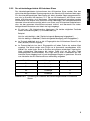
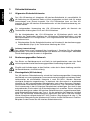
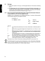
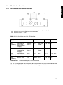
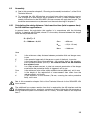
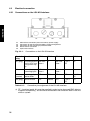
1
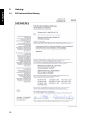
SIGUARD Laserscanner LS4 AS-Interface
Zusatzinformationen zur Technischen Anleitung
des SIGUARD Laserscanner LS4-4
SIGUARD Laser Scanner LS4 AS-Interface
Additional information to the Instruction Manual for the
SIGUARD Laser Scanner LS4-4
Technische Anleitung
Instruction Manual
GWA 4NEB 839 6069 12
2
607061
Die Technische Anleitung des SIGUARD Laserscanners LS4 AS-Interface enthält
Zusatzinformationen zur Technischen Anleitung des SIGUARD Laserscanners LS4-4
über bestimmungsgemäßen Einsatz, Projektierung, Montage, elektrische Installation
und Inbetriebnahme des Scanners mit AS-Interface-Anschluss. Ergänzende Informationen ersehen Sie in der Technischen Anleitung zum LS4-4 und im Benutzerhandbuch
von LS4soft. Diese drei Dokumentationen sowie die Software LS4soft sind Bestandteil
des Lieferumfangs und richten sich an Planer, Betreiber und Wartungspersonal von
Anlagen, die mit dem SIGUARD Laserscanner LS4 AS-Interface abgesichert sind.
DEUTSCH
Über die Technische Anleitung
Die Technischen Anleitungen und das Benutzerhandbuch sind sorgfältig aufzubewahren. Sie müssen während der gesamten Einsatzdauer des Scanners immer verfügbar
sein.
Sicherheits- und Warnhinweise sind mit dem Symbol
gekennzeichnet.
Hinweise zur Sicherheit von Lasergeräten sind mit dem Symbol
ENGLISCH
Alle Angaben der Technischen Anleitungen sowie des Benutzerhandbuchs, insbesondere die Sicherheitshinweise müssen unbedingt beachtet werden.
gekennzeichnet.
Die Siemens AG haftet nicht für Schäden, die durch unsachgemäße Benutzung
entstehen.
Zur sachgerechten Verwendung gehört auch die Kenntnis dieses Handbuchs.
Fassung des Inhalts:V1.0
Copyright Siemens AG 2003 All rights reserved
FRANZÖSISCH
Hinweise zu wichtigen Informationen sind mit dem Symbol L gekennzeichnet.
ITALIENISCH
Weitergabe sowie Vervielfältigung dieser Unterlage, Verwertung und Mitteilung ihres
lnhalts ist nicht gestattet, soweit nicht ausdrücklich zugestanden. Zuwiderhandlungen
verpflichten zu Schadenersatz. Alle Rechte vorbehalten, insbesondere für den Fall der
Patenterteilung oder GM-Eintragung
Technical Assistance:
Telefon:
+49 (0)9131-7-43833 (8°° -17°° MEZ)
Fax:
+49 (0)9131-7-42899
E-Mail:
[email protected]
Internet:
www.siemens.de/lowvoltage/technical-assistance
Technische Änderungen bleiben vorbehalten.
SPANISCH
English version starts on page 24
3
Inhaltsverzeichnis
DEUTSCH
1
Allgemeines . . . . . . . . . . . . . . . . . . . . . . . . . . . . . . . . . . . . . . . . . . . . . . . . . . . . . . . . . . . . . . . . . 5
1.1
1.2
1.3
2
Systemüberblick . . . . . . . . . . . . . . . . . . . . . . . . . . . . . . . . . . . . . . . . . . . . . . . . . . . . . . . . . . . . . 6
2.1
2.2
2.2.1
2.2.2
3
ENGLISCH
FRANZÖSISCH
4.3
4.3.1
4.3.2
4.3.3
ITALIENISCH
7
12
14
14
15
15
16
16
. . . . . . . . . . . . . . . . . . . . . . . . . . . . . . . . . . . . . . . . . . . . . . . . . . . . . . . . . . . . 16
Einbau in AS-Interface / Funktionskontrolle . . . . . . . . . . . . . . . . . . . . . . . . . . . . . . . . . . 16
Hinweise zu Störung und Fehlerbehebung . . . . . . . . . . . . . . . . . . . . . . . . . . . . . . . . . . . 17
Austausch eines sicherheitsgerichteten AS-Interface Slaves . . . . . . . . . . . . . . . . . . . . . 17
Sicheres Abschalten kontrollieren . . . . . . . . . . . . . . . . . . . . . . . . . . . . . . . . . . . . . . . . . . 19
Lieferumfang und Bestellhinweise . . . . . . . . . . . . . . . . . . . . . . . . . . . . . . . . . . . . . . . . . . . . . 21
Lieferumfang . . . . . . . . . . . . . . . . . . . . . . . . . . . . . . . . . . . . . . . . . . . . . . . . . . . . . . . . . . 21
Bestellhinweise LS4 AS-Interface und Zubehör LS4 AS-Interface . . . . . . . . . . . . . . . . . 21
Anhang . . . . . . . . . . . . . . . . . . . . . . . . . . . . . . . . . . . . . . . . . . . . . . . . . . . . . . . . . . . . . . . . . . . . 22
9.1
SPANISCH
4
Aufbau . . . . . . . . . . . . . . . . . . . . . . . . . . . . . . . . . . . . . . . . . . . . . . . . . . . . . . . . . . . . . . .
Montage . . . . . . . . . . . . . . . . . . . . . . . . . . . . . . . . . . . . . . . . . . . . . . . . . . . . . . . . . . . . . .
Berechnung des Sicherheitsabstandes / Gesamtreaktionszeit
(Gesamt-Ansprechzeit) für AS-Interface Applikationen . . . . . . . . . . . . . . . . . . . . . . . . . .
Elektrischer Anschluss . . . . . . . . . . . . . . . . . . . . . . . . . . . . . . . . . . . . . . . . . . . . . . . . . .
Anschlüsse des LS4 AS-Interface . . . . . . . . . . . . . . . . . . . . . . . . . . . . . . . . . . . . . . . . . .
Installationsvorschriften . . . . . . . . . . . . . . . . . . . . . . . . . . . . . . . . . . . . . . . . . . . . . . . . . .
Spannungsversorgung AS-Interface . . . . . . . . . . . . . . . . . . . . . . . . . . . . . . . . . . . . . . . .
Technische Daten und Maßzeichnungen . . . . . . . . . . . . . . . . . . . . . . . . . . . . . . . . . . . . . . . . 19
8.1
8.2
9
10
10
10
11
Wartung und Prüfung . . . . . . . . . . . . . . . . . . . . . . . . . . . . . . . . . . . . . . . . . . . . . . . . . . . . . . . . 17
6.1
6.2
8
Allgemeine Sicherheitshinweise . . . . . . . . . . . . . . . . . . . . . . . . . . . . . . . . . . . . . . . . . . .
Bestimmungsgemäßer Gebrauch . . . . . . . . . . . . . . . . . . . . . . . . . . . . . . . . . . . . . . . . . .
Einsatzgebiete (AS-Interface) . . . . . . . . . . . . . . . . . . . . . . . . . . . . . . . . . . . . . . . . . . . . .
Organisatorische Maßnahmen . . . . . . . . . . . . . . . . . . . . . . . . . . . . . . . . . . . . . . . . . . . .
Inbetriebnahme
5.1
5.2
6
7
7
8
9
Aufbau, Montage und elektrischer Anschluss (AS-Interface-seitig) . . . . . . . . . . . . . . . . . . 12
4.1
4.2
4.2.1
5
Kurzbeschreibung LS4 AS-Interface . . . . . . . . . . . . . . . . . . . . . . . . . . . . . . . . . . . . . . . . .
Kurzbeschreibung AS-Interface Safety at Work . . . . . . . . . . . . . . . . . . . . . . . . . . . . . . . .
Der AS-Interface Sicherheitsmonitor . . . . . . . . . . . . . . . . . . . . . . . . . . . . . . . . . . . . . . . . .
Der sicherheitsgerichtete AS-Interface Slave . . . . . . . . . . . . . . . . . . . . . . . . . . . . . . . . . .
Sicherheitshinweise . . . . . . . . . . . . . . . . . . . . . . . . . . . . . . . . . . . . . . . . . . . . . . . . . . . . . . . . . 10
3.1
3.2
3.3
3.4
4
Zulassungen . . . . . . . . . . . . . . . . . . . . . . . . . . . . . . . . . . . . . . . . . . . . . . . . . . . . . . . . . . . 5
Begriffsdefinitionen ( zu AS-Interface) . . . . . . . . . . . . . . . . . . . . . . . . . . . . . . . . . . . . . . . . 5
Abkürzungen . . . . . . . . . . . . . . . . . . . . . . . . . . . . . . . . . . . . . . . . . . . . . . . . . . . . . . . . . . . 6
EG Konformitätserklärung . . . . . . . . . . . . . . . . . . . . . . . . . . . . . . . . . . . . . . . . . . . . . . . . 22
Allgemeines
Der Sicherheits-Flächenscanner LS4 ist eine optoelektronische Schutzeinrichtung
(Active Opto-electronic Protective Device, AOPD) Typ 3 gemäß EN/IEC 61496-1, -3.
Der AS-Interface-Adapter ist eine Ergänzung des LS4 zur sicheren Anbindung dieses
Gerätes an AS-Interface.
1.1
DEUTSCH
1
Zulassungen
Begriffsdefinitionen ( zu AS-Interface)
Ausgangsschaltelement (Sicherheitsausgang) des AS-Interface-Sicherheitsmonitors
Von der Logik des Monitors betätigtes Element, das in der Lage ist, die nachgeordneten Steuerungsteile sicher abzuschalten. Das Ausgangsschaltelement darf nur bei
bestimmungsgemäßer Funktion aller Komponenten in den Ein-Zustand gehen oder
dort verbleiben.
Freigabekreis
Die einem Kanal des AS-Interface-Sicherheitsmonitors zugeordneten sicherheitsgerichteten AS-Interface-Komponenten und Funktionsbausteine, die für die Entriegelung
des Maschinenteils verantwortlich sind, welches die gefahrbringende Bewegung
erzeugt.
Integrierter AS-Interface Slave
Komponente, bei dem Sensor- und / oder Aktuatorfunktion zusammen mit dem Slave
in einer Einheit zusammengefasst sind.
AS-Interface Master
Komponente zur Datenübertragung, die das logische und zeitliche Verhalten auf der
AS-Interface-Leitung steuert.
PORTUGUESE
1.2
ITALIENISCH
TÜV Süddeutschland Group
Ridlerstr. 65
80339 München
SPANISCH
EG-Baumusterprüfung (Europa)
nach EN IEC 61496 Teil 1 und Teil 3 wurde erteilt durch:
FRANZÖSISCH
ENGLISCH
Der Distanzsensor SIGUARD Laserscanner LS4 AS-Interface wurde unter Berücksichtigung geltender europäischer Richtlinien und Normen entwickelt und gefertigt.
Sicherheitsausgang
Siehe Ausgangsschaltelement.
5
DEUTSCH
Sicherheitsgerichteter Eingangsslave
Slave, der den sicherheitsgerichteten Zustand Ein oder Aus des angeschlossenen
Sensors oder Befehlsgeräts einliest und zum Master bzw. Sicherheitsmonitor überträgt.
Sicherheitsgerichteter AS-Interface Slave
Slave zum Anschluss sicherheitsgerichteter Sensoren, Aktuatoren und anderer Geräte.
ENGLISCH
Sicherheitsmonitor
Komponente, die die sicherheitsgerichteten Slaves und die korrekte Funktion des
Netzes überwacht.
Slave
Komponente zur Datenübertragung, die vom Master zyklisch über ihre Adresse
angesprochen wird und nur dann eine Antwort generiert.
FRANZÖSISCH
Standardslave
Slave zum Anschluss nicht sicherheitsgerichteter Sensoren, Aktuatoren und anderer
Geräte.
1.3
ITALIENISCH
2
Abkürzungen
AS-Interface
Aktuator Sensor Interface
BWS
Berührungslos wirkende Schutzeinrichtung
EMV
Elektro-Magnetische Verträglichkeit
FE
Funktionserde
PELV
Protective Extra-Low Voltage (Schutzkleinspannung)
SPS
Speicher Programmierbare Steuerung
Systemüberblick
SPANISCH
PORTUGUESE
Der Flächenscanner LS4 ist eine berührungslos wirkende Schutzeinrichtung BWS vom
Typ 3. Er tastet permanent das parametrierte und angewählte Schutzfeld ab und
schaltet bei Verletzung dieses Schutzfeldes seine Sicherheitsschaltausgänge OSSD
ab. Er unterbricht somit eine Gefahr-bringende Bewegung. Während des Betriebs
können bis zu 4 parametrierte Schutz- und Warnfelder über lokale Sensorsignale
umgeschaltet werden. Je nach Parametrierung gibt der Scanner ein nicht Sicherheitsrelevantes Warnsignal aus, falls die Verschmutzung der Frontscheibe zu stark ist und /
oder falls ein ebenfalls parametrierbares Warnfeld verletzt wird.
6
Zusätzlich zum sicherheitsrelevanten Schutzfeld kann ein nicht sicheres Warnfeld
parametriert werden, bei dessen Verletzung nicht abgeschaltet, sondern ein Warnsignal gesetzt wird, das ebenfalls im zyklisch mit dem Bus-Master ausgetauschten
Telegramm verpackt wird und abgerufen werden kann.
Obwohl die Datenübertragung sicherheitsrelevant ist, darf das Warnsignal nicht
sicherheitsrelevant verwendet werden, da es nicht als sicheres Signal vom Scanner
geliefert wird.
Schutzfeld und Warnfeld bilden zusammen ein Schutzfeldpaar. Sie werden stets
gemeinsam aktiviert und können aus maximal 4 Schutzfeldpaaren ausgewählt werden.
Alle Schutzfeldpaare sowie die zulässigen Umschaltungen werden während der
Inbetriebnahme an die jeweilige Anwendung angepasst. Die Umschaltung der Schutzfeldpaare während des Betriebes erfolgt über lokale Sensorsignale.
Kurzbeschreibung AS-Interface Safety at Work
Das Aktuator-Sensor-Interface (AS-Interface) ist etabliert als System zur Vernetzung
vornehmlich binärer Sensoren und Aktuatoren auf der untersten Ebene der Automatisierungshierarchie. Die hohe Zahl der installierten Systeme, die einfache Handhabung
und das zuverlässige Betriebsverhalten machen AS-Interface auch für den Bereich der
Maschinensicherheit interessant.
PORTUGUESE
2.2
FRANZÖSISCH
Die Abtasteinheit im Scanner rotiert und sendet / empfängt nach jeweils 0,36° einen
Laserpuls. Dadurch wird ein Kreissektor von bis zu 190° abgetastet, in deren
Mittelpunkt sich der LS4 AS-Interface befindet. Das zu überwachende Schutzfeld wird
begrenzt durch eine beliebig geformte Kurve um den Scanner herum, deren maximaler
Abstand zum Scannermittelpunkt 4 m beträgt. Wird ein Objekt zwischen dieser
Begrenzungslinie und dem Scanner detektiert, das aktive Schutzfeld also verletzt,
schaltet der Scanner seinen sicherheitsrelevanten OSSD - Ausgang ab, über AS-Interface wird der Zustand der OSSDs als Datensequenz zyklisch an den AS-Interface
Sicherheitsmonitor übertragen, der über die Schutzfeldverletzung informiert wird und
dann die Gefahr-bringende Bewegung zum Stillstand bringt.
ITALIENISCH
Der Flächenscanner LS4 AS-Interface sendet sehr kurze Laserimpulse und misst die
Laufzeit bis zum Auftreffen eines Impulses auf ein Objekt sowie dessen Remission
zum Empfänger im LS4 AS-Interface. Aus der Laufzeit wird im Gerät die Entfernung
zwischen Objekt und LS4 AS-Interface berechnet.
ENGLISCH
Kurzbeschreibung LS4 AS-Interface
SPANISCH
2.1
DEUTSCH
Aufgrund seiner integrierten AS-Interface Schnittstelle ist der LS4 AS-Interface an das
Bussystem AS-Interface anbindbar. Befindet sich eine Person bzw. das Hindernis
innerhalb vorher festgelegter Schutzfelder, wird eine sicherheitsgerichtete Schaltfunktion ausgelöst und die über AS-Interface und den AS-Interface Sicherheitsmonitor
abgesicherte Maschine in den sicheren Zustand gebracht. Das Rücksetzen dieser
Schaltfunktion erfolgt erst bei freiem Schutzfeld, abhängig von der Betriebsart,
automatisch oder nach Quittierung über den AS-Interface Sicherheitsmonitor.
7
DEUTSCH
Das sichere AS-Interface-System ist für Sicherheitsanwendungen bis Kategorie 4 nach
EN 954-1 vorgesehen. Es ist ein Mischbetrieb von AS-Interface-Standardkomponenten
und sicherheitsgerichteten AS-Interface-Komponenten möglich.
L Eine ausführliche Beschreibung der sicheren AS-Interface-Übertragung finden Sie
in der Technischen Anleitung des AS-Interface Sicherheitsmonitors Kapitel 11.
2.2.1 Der AS-Interface Sicherheitsmonitor
ENGLISCH
Der AS-Interface-Sicherheitsmonitor überwacht innerhalb eines AS-Interface-Systems,
entsprechend der vom Anwender per Konfigurationssoftware angegebenen Konfiguration, die ihm zugeordneten sicherheitsgerichteten AS-Interface Slaves. Je nach
Gerätevariante stehen bis zu zwei abhängige oder unabhängige Freigabekreise mit
Schützkontrolle zur Verfügung. Im Fall einer Stopp-Anforderung oder eines Defektes
schaltet der AS-Interface-Sicherheitsmonitor im Schutzbetrieb das System mit einer
Reaktionszeit von maximal 40 ms bei System-Vollausbau sicher ab. Es ist dabei
möglich, bis zu 31 sicherheitsgerichtete AS-Interface Slaves in ein System einzubinden.
FRANZÖSISCH
a
c
b
e
d
i
ITALIENISCH
f
j
h
g
a
SPANISCH
b
c
d
e
SPS/Steuerung mit AS-Interface
Master
Standard-Modul
AS-Interface Sicherheitsmonitor
NOT-AUS-Taster mit integrierter
AS-Interface-Schnittstelle
sicheres AS-Interface Eingangsmodul
f
g
h
i
j
Positionsschalter mit integrierter ASInterface-Schnittstelle
Standard-Modul
Sicherheits-Lichtgitter mit integrierter
AS-Interface-Schnittstelle
AS-Interface Netzteil
Sicherheits-Lichtschranke mit integrierter AS-Interface-Schnittstelle
Abb. 2.2-1: Sicherheits- und Standard-Komponenten in einem AS-InterfaceNetzwerk
PORTUGUESE
Innerhalb eines AS-Interface-Systems können mehrere AS-Interface-Sicherheitsmonitore eingesetzt werden. Ein sicherheitsgerichteter AS-Interface Slave kann dabei von
mehreren AS-Interface-Sicherheitsmonitoren überwacht werden.
8
Es wird nur 1 Bit Nutzinformation übertragen. Die beiden möglichen Zustände
haben die Bedeutung frei (=1) und nicht frei (=0).
Beispiel:
Not-Aus nicht betätigt = frei ("Gefahr-bringende Bewegung freigegeben")
Not-Aus betätigt = nicht frei ("Gefahr-bringende Bewegung nicht freigegeben")
Im Zustand nicht frei wird an die 4 Eingangsbits des AS-Interface Slave-ICs der
Wert (0,0,0,0) statisch angelegt.
z
Im Zustand frei wird an den 4 Eingangsbits mit jedem Zyklus ein anderer Wert
angelegt. Die Werte stellen eine Folge von 8 paarweise verschiedenen 4-BitWerten dar, wobei jeder Slave im System seine eigene eindeutige Folge besitzt.
Nach erfolgreicher Übertragung der achten Folge wird auf die erste Folge
weitergeschaltet (Endlosschleife). Die Folge wird in einer Codetabelle des ASInterface Slaves abgelegt und ist nach festgelegten Regeln zu generieren. Sie wird
vom Hersteller des AS-Interface Slaves werksseitig vergeben.
Datenbit
Lichtweg frei
Lichtweg unterbrochen
D0
Codefolge
0
D1
Codefolge
0
D2
Codefolge
0
D3
Codefolge
0
ITALIENISCH
z
ENGLISCH
z
FRANZÖSISCH
Die sicherheitsgerichteten Informationen des AS-Interface Slave werden über den
nicht sicherheitsgerichteten Übertragungskanal des Standard AS-Interface übertragen.
Für die sicherheitsgerichtete Übertragung gilt dabei derselbe Übertragungsmechanismus wie im Standard AS-Interface, d. h. die am AS-Interface-IC des Slaves anstehende 4-Bit-Information wird übertragen. Übertragungstechnisch betrachtet werden
Informationen vom Master zum Slave und zurück übertragen, der sicherheitstechnisch
relevante Informationsfluss erfolgt jedoch vom Slave zum AS-Interface-Sicherheitsmonitor, der den gesamten Informationsaustausch "mithört" und überwacht. Die sicherheitsgerichteten Nutzdaten sind dabei wie folgt festgelegt:
DEUTSCH
2.2.2 Der sicherheitsgerichtete AS-Interface Slave
PORTUGUESE
SPANISCH
Tabelle 2.2-1: Zuordnung der Datenbits des sicherheitsgerichteten AS-Interface
Slaves
9
DEUTSCH
3
Sicherheitshinweise
3.1
Allgemeine Sicherheitshinweise
Der LS4 AS-Interface mit integrierter AS-Interface-Schnittstelle ist ausschließlich für
die Anbindung an AS-Interface Safety at Work vorgesehen und darf nicht für andere
Anwendungen zum Einsatz kommen. Der LS4 AS-Interface kann nur über ASInterface und den AS-Interface Sicherheitsmonitor mit der Maschinensteuerung verbunden werden.
ENGLISCH
Zur sachgerechten Verwendung des LS4 AS-Interface gehört die Kenntnis der
Technischen Anleitung des LS4-4 und LS4 AS-Interface.
Für die Inbetriebnahme des LS4 AS-Interface an AS-Interface gehört auch die
Kenntnis der Technischen Anleitung des AS-Interface Sicherheitsmonitors und des
Benutzerhandbuchs zur Konfigurations- und Diagnosesoftware des AS-Interface Sicherheitsmonitors.
FRANZÖSISCH
L Bitte beachten Sie die Sicherheitshinweise und Hinweise für den bestimmungsgemäßen Betrieb (Kap. 3) der Technischen Anleitung des LS4-4.
Achtung Laserstrahlung!
Der Laserscanner ist ein Lasergerät der Laserklasse 1. Beachten Sie die geltenden
gesetzlichen und örtlichen Bestimmungen zum Betrieb von Laseranlagen. Vermeiden
Sie die Anbringung des Scanners in Augenhöhe.
3.2
Bestimmungsgemäßer Gebrauch
ITALIENISCH
Der Schutz von Betriebspersonal und Gerät ist nicht gewährleistet, wenn das Gerät
nicht entsprechend seiner bestimmungsgemäßen Verwendung eingesetzt wird.
Eingriffe und Veränderungen an den Geräten, außer den in dieser Anleitung ausdrücklich beschriebenen, sind nicht zulässig.
3.3
Einsatzgebiete (AS-Interface)
SPANISCH
Der AS-Interface Sicherheitsmonitor erlaubt bei bestimmungsgemäßer Verwendung
den Betrieb von sensorgesteuerten Personenschutzeinrichtungen und weiteren Sicherheitsbauteilen bis einschließlich Kategorie 4 nach EN 954-1. Werden Sensoren
niedrigerer Kategorien angeschlossen, so bestimmt sich die maximal zu erreichende
Kategorie für den entsprechenden Sicherheitspfad nach diesen Sensoren. Beispielsweise können Laserscanner nach EN 61496-3 maximal als Typ 3 klassifiziert werden.
Sind Laserscanner in den AS-Interface Sicherheitskreis einbezogen, lässt sich für den
entsprechenden Pfad maximal die Sicherheitskategorie 3 erreichen. Davon unberührt
bleibt eine etwaige am selben AS-Interface Sicherheitsmonitor angeschlossene Mehrstrahl-Sicherheitslichtschranke des Typs 4, für den weiterhin die Kategorie 4 möglich
bleibt. Der AS-Interface Sicherheitsmonitor übernimmt auch die für alle nicht handgeführten Maschinen obligatorische NOT-AUS Funktion (Stop-Kategorie 0 oder 1), die
dynamische Überwachung der Wiederanlauf-Funktion und die Schützkontroll-Funktion.
Beispiele für den Einsatz des AS-Interface Sicherheitsmonitor:
PORTUGUESE
10
z
Druck- und Papierverarbeitungsmaschinen, Zuschneidemaschinen
z
Verpackungsmaschinen einzeln und im Verbund
z
Nahrungsmittelmaschinen
z
Stück- und Schüttgut Förderanlagen
z
Arbeitsmaschinen der Gummi- und Kunststoffindustrie
z
Montageautomaten und Handhabungsgeräte
Sicherheitsvorschriften
Beachten Sie die örtlich geltenden gesetzlichen Bestimmungen und die Vorschriften
der Berufsgenossenschaften.
Qualifiziertes Personal
Die Montage, Inbetriebnahme und Wartung der Geräte darf nur von qualifiziertem
Fachpersonal durchgeführt werden. Elektrische Arbeiten dürfen nur von ElektroFachkräften durchgeführt werden.
Reparatur
Reparaturen, insbesondere das Öffnen des Gehäuses, darf nur vom Hersteller oder
einer vom Hersteller autorisierten Person in sauberer Umgebung vorgenommen
werden (z.B. bei Austausch einer verkratzten Scannerscheibe).
Entsorgung
L Elektronikschrott ist Sondermüll! Beachten Sie die örtlichen Vorschriften zu dessen
Entsorgung! Der SIGUARD Laserscanner LS4 AS-Interface enthält keinerlei Batterien, die vor der Entsorgung des Gerätes zu entfernen wären.
ITALIENISCH
Dokumentation
Alle Angaben dieser Technischen Anleitung, insbesondere der Abschnitte "Sicherheitshinweise" und "Inbetriebnahme" müssen unbedingt beachtet werden. Bewahren Sie
diese Technische Anleitung sorgfältig auf. Sie sollte immer verfügbar sein.
SPANISCH
Organisatorische Maßnahmen
FRANZÖSISCH
ENGLISCH
Ausgedehnte Bearbeitungsmaschinen mit mehreren Steuerelementen und Sicherheitssensorik für die Bereiche Holz und Metall
PORTUGUESE
3.4
z
DEUTSCH
AS-Interface Safety at Work findet seine wirtschaftliche Anwendung in jedem Fall dort,
wo sich der Standard AS-Interface Bus wegen seiner Vorteile als lokaler Bus mit
geringem Verdrahtungsaufwand rechnet. So können unter Verwendung des ASInterface Sicherheitsmonitors als Busteilnehmer bereits bestehende AS-InterfaceBuskonfigurationen problemlos erweitert und Sicherheitsbauteile mit entsprechender
AS-Interface Schnittstelle problemlos eingeschleift werden. Bestehende AS-Interface
Master und AS-Interface Netzteile können in der Regel weiter verwendet werden.
Einige der wesentlichsten Einsatzgebiete seien hier genannt:
11
DEUTSCH
4
Aufbau, Montage und elektrischer Anschluss (AS-Interfaceseitig)
4.1
Aufbau
Der LS4 AS-Interface besteht aus dem Laserscanner LS4 und dem LS4 AS-InterfaceAdapter, die bereits werkseitig miteinander verbunden sind. Der LS4 AS-InterfaceAdapter realisiert die Aufbereitung der Standard-LS4 Daten an AS-Interface.
ENGLISCH
1
2
FRANZÖSISCH
1
2
AS-Interface-Adapter
Laserscanner LS4
Abb. 4.1-1: Aufbau des LS4 AS-Interface
ITALIENISCH
Über Stecker X1 (PIN1, PIN3) werden die sicherheitsrelevanten OSSD-Signale und die
Diagnosedaten des LS4 über AS-Interface zum AS-Interface Sicherheitsmonitor übertragen.
Aufgrund seiner hohen Stromaufnahme benötigt der LS4 AS-Interface eine separate
24 Volt-Spannungsversorgung, die ebenfalls über Stecker X1 (PIN 2, PIN4) angelegt
wird.
Die Buchse X3 ist für die externe Umschaltung der 4 Schutz- und Warnfeldpaare
zuständig.
SPANISCH
Stecker X4 des LS4 AS-Interface ist für den Anschluss einer Restart-Taste vorgesehen. Diese Taste dient einerseits zum Entriegeln der Scanner-internen Anlauf-/
Wiederanlaufsperre, falls diese aktiviert wurde. Darüber hinaus wird mit dieser Taste
die Fehlerquittierung vorgenommen, die benötigt wird, wenn der Scanner in Störung
gegangen ist.
Während der Betätigung der Restart-Taste sind die sicheren Ausgänge OSSD 1 und
OSSD 2 des LS4 abgeschaltet, die Anzeige am Scanner leuchtet rot. Die Dauer des
Rücksetz-Signals muß zwischen 2 und 3 Sekunden betragen. Die zulässige Länge der
Restart Leitung beträgt 25 m.
PORTUGUESE
12
Da die Stromversorgung des PC-Adapters aus dem PC COM-Port erfolgt, muss dieser
„RS232-compliant“ sein, also bei einer Last von 3 kOhm noch eine Spannung von 5
Volt liefern können. Die bei Notebook-PCs gelegentlich vorkommende Angabe
„RS232-compatible“ reicht nicht aus. Der LS4 AS-Interface-Adapter liest den Datenstrom zwar mit, beeinflusst ihn aber in keiner Weise. Diese Schnittstelle entspricht
deshalb funktionell der RS232-Schnittstelle über SUB-D-Stecker am LS4.
DEUTSCH
SPANISCH
ITALIENISCH
L Eine ausführliche Beschreibung der Software finden Sie im Benutzerhandbuch
LS4soft.
ENGLISCH
Zur Parametrierung sowie zur lokalen Diagnose des LS4 AS-Interface wird ein PC mit
der Software LS4soft über eine RS232- Schnittstelle, das Programmierkabel und die
optische Schnittstelle an der Oberseite des LS4 AS-Interface-Adapters angeschlossen.
Der Kabelabgang des PC-Adapters am LS4 AS-Interface zeigt dabei in Richtung
Schutzfeld. Ein starker Magnet im PC-Adapter sorgt nicht nur für mechanischen Halt
sondern signalisiert gleichzeitig einem Reedkontakt im Gerät, dass der PC-Adapter
angeschlossen ist.
FRANZÖSISCH
Über die Adressierbuchse X2 kann optional neben der Bus-Adressiermöglichkeit über
den M12-Gerätestecker X1 dem LS4 AS-Interface eine Busadresse vergeben werden.
Dafür wird ein handelsübliches AS-Interface Programmiergerät für Busadresseneingabe benutzt.
PORTUGUESE
Abb. 4.1-2: Verbindung von PC mit LS4 AS-Interface über optischen PC-Adapter
13
4.2
Montage
DEUTSCH
L Siehe dazu Kapitel 6, Planungs- und Montagehinweise der Technischen Anleitung
LS4-4.
L Für die Montage des LS4 AS-Interface sind längere Befestigungsschrauben von
mindestens 50 mm Länge und einem Durchmesser von 5 mm zu verwenden, ansonsten gelten die Montagehinweise zum SIGUARD Laserscanner LS4. Die Bohrmaße entnehmen Sie bitte den Maßzeichnungen in Kap. 7.
4.2.1 Berechnung des Sicherheitsabstandes / Gesamtreaktionszeit (GesamtAnsprechzeit) für AS-Interface Applikationen
ENGLISCH
Allgemein gilt zur Berechnung des Sicherheitsabstandes S zwischen Gefahrenstelle
und Schutzfeld folgende Formel gemäß EN 999:
S = (K xT) + C
C = 1200 mm – 0,4 H
FRANZÖSISCH
CMIN
= 850 mm
HMIN
= 15(d - 15 mm)
HMAX
= 1000 mm
dabei ist:
S
K
ITALIENISCH
T
C
CMIN
H
d
der Mindestsicherheitsabstand zwischen Schutzfeld und Gefahrenstelle in
mm
die Annäherungsgeschwindigkeit des Körperteils bzw. der Person in mm/
ms
die Nachlaufzeit der Maschine + die Reaktionszeit der optoelektronischen
Schutzeinrichtung (AOPD) + die Reaktionszeit des AS-Interface Bussystems in ms
Sicherheitsbezogene Konstante zur Berücksichtigung des Eindringens in
den Gefahrenbereich vor Auslösen der Schutzeinrichtung, Einheit in mm
Minimalwert der sicherheitsbezogenen Konstante (850mm), Einheit in mm
Höhe der Meßwerterfassungsebene ab Bezugspunkt, Einheit in mm
Auflösung des Scanners (70 mm, schutzfeldweit), Eineit in mm
SPANISCH
Siehe dazu Kap. 5.4.8 der Technischen Anleitung SIGUARD Laserscanner LS4
Zur Reaktionszeit (T) muß die durch AS-Interface und den AS-Interface Sicherheitsmonitor zusätzlich benötigte Bussystem-Reaktionszeit von maximal 40 ms (bei ASInterface Systemvollausbau mit 31 Slaves) addiert werden.
PORTUGUESE
14
Elektrischer Anschluss
DEUTSCH
4.3.1 Anschlüsse des LS4 AS-Interface
X1
X3
X4
Anschluss AS-Interface (Busanschluss und 24 Volt-Spannungsversorgung)
Anschluss AS-Interface Adressen-Programmiergerät
Anschluss Schutzfelder-Umschaltung
Anschluss Restart – Taste
Optische PC-Schnittstelle
FRANZÖSISCH
X1
X2
X3
X4
X5
X2
ENGLISCH
X5
Abb. 4.3-1: Anschluss des LS4 AS-Interface
PIN 1
PIN 2
PIN 3
PIN 4
X1
Busanschluss
(Stecker) und 24 VoltSpannungsversorgung
AS-Interface +
0V
AS-Interface -
+ 24 VDC FE
X2
AS-Interface +
n.c.
AS-Interface -
n.c.
n.c.
X3
Schutzfeldum(Buchse) schaltung
SF 1
SF 2
SF 3
SF 4
+ 24 VDC
X4
Restart-Taste
(Stecker)
n.c.
Restart n.c.
BusadressenProgrammierEingang
PIN 5
ITALIENISCH
Funktion
SPANISCH
Buchse/
Stecker
+ 24 VDC n.c.
Tabelle 4.3-1: Anschlussbelegung LS4 AS-Interface
L FE – Funktionserde: Der Anschluss der Funktionserde am Gerät ist erforderlich und
ist mit der Funktionserde der Maschine oder Anlage zu verbinden.
15
PORTUGUESE
4.3
DEUTSCH
L Die M12-Verbindungskabel vom LS4 AS-Interface Anschluss X1 zum AS-Interface
Flachkabel über den AS-Interface Flachkabelanschluss-Adapter (siehe Kap. 8 Lieferumfang und Bestellhinweise) sollten dabei so kurz wie möglich sein (max. 2 m).
Am AS-Interface Adapter 3RG7838-1DG ist intern die Funktionserde von X1-PIN5
auf zwei seiner 4 Schrauben-Verschlüsse des Adaptermoduls verdrahtet. Eine Erdungsleitung (oder Erdungsdraht) kann somit vom AS-Interface Adapter zur Anlage
oder Maschine verlegt werden.
4.3.2 Installationsvorschriften
ENGLISCH
Die allgemeinen Sicherheitshinweise in Kapitel 3 sind zu beachten. Die elektrische
Installation ist von eingewiesenem Fachpersonal durchzuführen.
4.3.3 Spannungsversorgung AS-Interface
Das AS-Interface-Netzteil zur Versorgung der AS-Interface-Komponenten (z.B. LS4
AS-Interface) muß eine sichere Netztrennung gemäß IEC 60742 aufweisen und
kurzzeitige Netzausfälle bis zu 20 ms überbrücken.
FRANZÖSISCH
5
Inbetriebnahme
5.1
Einbau in AS-Interface / Funktionskontrolle
L Siehe dazu auch die Technische Anleitung des AS-Interface Sicherheitsmonitors
Kapitel 7 (Funktion und Inbetriebnahme) und die Technische Anleitung SIGUARD
Laserscanner LS4-4 Kapitel 10 (Inbetriebnahme).
ITALIENISCH
Gehen Sie bei Montage und Inbetriebnahme wie folgt vor:
SPANISCH
PORTUGUESE
16
1
Adressieren Sie den AS-Interface Slave
Die Adressierung erfolgt über den M12-Gerätestecker für AS-Interface Busanschluss und Versorgungsspannung (X1) oder über die AS-Interface Adressierbuchse (X4), mit handelsüblichen AS-Interface Adressiergeräten. Jede Adresse
darf nur einmal in einem AS-Interface Netz verwendet werden, mögliche
Busadressen1...31.
2
Installieren Sie den sicheren AS-Interface Slave in AS-Interface
Der Anschluß erfolgt über einen AS-Interface Adapter für Anschluss von AS-Interface Datenkabel (gelb) und Hilfsversorgung 24V DC (schwarz) sowie mit einem
Verbindungskabel 5polig von AS-Interface Adapter zu M12-Gerätestecker X1 des
LS4 AS-Interface.
3
Kontrollieren Sie die 24 V Versorgung des Sensors
Die rote LED leuchtet am LS4 AS-Interface auf.
Die Inbetriebnahme und Konfiguration des sicheren AS-Interface Slave erfolgt jetzt mit der Konfigurations- und Diagnosesoftware des AS-Interface
Sicherheitsmonitors.
DEUTSCH
5
ENGLISCH
Kontrollieren Sie das freie Schutzfeld des LS4 AS-Interface
Die grüne LED leuchtet nach ca. 20 Sekunden bei freiem Schutzfeld auf. Der LS4
AS-Interface ist damit betriebsbereit zum Einlernen der Codetabelle in den AS-i Sicherheitsmonitor
L Zur Funktionsfähigkeit des LS4 AS-Interface muß die M12-Buchse X3 für
Schutzfelder-Umschaltung vorher beschaltet werden, d.h. ein Schutzfeld muß
aktiviert sein. Dazu kann man den Schutzfeld-Brückenstecker für Schutzfeld-1Beschaltung 3RG7838-1DF verwenden (Kapitel 10, Lieferumfang und Bestellhinweise, Zubehör LS4 AS-Interface).
L Das Schutzfeld des LS4 AS-Interface darf für die Systemintegration, d.h. beim
Einlernen der Codetabelle des sicheren AS-Interface Slaves durch den AS-Interface Sicherheitsmonitor, nicht unterbrochen sein.
L Siehe dazu die Technische Anleitung des LS4, Kapitel 16 (Fehlercodes und deren
Ursachen) sowie die Technische Anleitung des AS-Interface Sicherheitsmonitors,
Kapitel 9 (Statusmeldung, Störung und Fehlerbehebung).
6
Wartung und Prüfung
6.1
Austausch eines sicherheitsgerichteten AS-Interface Slaves
Ist ein sicherheitsgerichteter AS-Interface Slave defekt, ist sein Austausch auch ohne
PC und Neukonfiguration des AS-Interface Sicherheitsmonitors mit Hilfe der Taste
SERVICE am AS-Interface Sicherheitsmonitor möglich.
PORTUGUESE
SPANISCH
L Siehe dazu auch die Technische Anleitung des AS-Interface Sicherheitsmonitors,
Kapitel 9.4 (Austausch eines defekten sicherheitsgerichteten AS-Interface Slaves).
FRANZÖSISCH
Hinweise zu Störung und Fehlerbehebung
ITALIENISCH
5.2
4
17
Gehen Sie beim Geräteaustausch wie folgt vor:
DEUTSCH
ENGLISCH
FRANZÖSISCH
ITALIENISCH
1
Trennen Sie den defekten AS-Interface Slave von der AS-Interface Leitung
Der AS-Interface Sicherheitsmonitor stoppt das System.
2
Betätigen Sie die SERVICE-Taste am AS-Interface Sicherheitsmonitor
3
Installieren Sie den neuen AS-Interface Slave
L AS-Interface Slaves von Siemens besitzen im Werksauslieferungszustand die
Busadresse 0. Bei Austausch programmiert der AS-Interface Master das Ersatzgerät automatisch mit der bisherigen Busadresse des defekten Gerätes.
Ein Umadressieren dieses Ersatzgerätes auf die Busadresse des defekten Gerätes ist damit nicht notwendig.
4
Kontrollieren Sie die 24 V Versorgung des Sensors über AS-Interface
Die rote LED leuchtet am LS4 AS-Interface auf.
5
Kontrollieren Sie das freie Schutzfeld des LS4 AS-Interface
Die grüne LED leuchtet nach ca. 20 Sekunden bei freiem Schutzfeld auf. Der LS4
AS-Interface ist damit betriebsbereit zum Einlernen der Codetabelle in den AS-Interface Sicherheitsmonitor.
L Das Schutzfeld des LS4 AS-Interface darf für die Systemintegrierung, d.h.
beim Einlernen der Codetabelle des sicheren AS-Interface Slaves durch den
AS-Interface Sicherheitsmonitor, nicht unterbrochen sein.
6
Betätigen Sie die SERVICE-Taste am AS-Interface Sicherheitsmonitor
7
Betätigen Sie die AS-Interface-seitige Start-Taste zum Wiederanlauf des ASInterface Systems
L Der System-Wiederanlauf erfolgt entsprechend der AS-Interface-seitigen Konfiguration einer manuellen Wiederanlaufsperre oder eines automatischen Wiederanlaufs im AS-i Sicherheitsmonitor (siehe dazu das Benutzerhandbuch
Konfigurations- und Diagnosesoftware für AS-Interface Sicherheitsmonitor)
SPANISCH
Mit dem erstmaligen Drücken der SERVICE-Taste wird festgestellt, ob genau ein ASInterface Slave fehlt. Dieser wird im Fehlerspeicher des AS-Interface Sicherheitsmonitors vermerkt. Der AS-Interface Sicherheitsmonitor wechselt in den Konfigurationsbetrieb. Mit dem zweiten Drücken der SERVICE-Taste wird die Codefolge des neuen ASInterface Slave eingelernt und auf Korrektheit geprüft. Ist diese in Ordnung, wechselt
der AS-Interface Sicherheitsmonitor wieder in den Schutzbetrieb.
Überprüfen Sie nach dem Austausch eines defekten sicherheitsgerichteten ASInterface Slaves unbedingt die korrekte Funktion des neuen AS-Interface Slaves.
PORTUGUESE
18
Dazu ist der sichere AS-Interface-Slave einmal pro Jahr zu aktivieren und das
Schaltverhalten durch Beobachtung der Sicherheitsausgänge des AS-Interface-Sicherheitsmonitors zu kontrollieren.
Technische Daten und Maßzeichnungen
Sicherheitskategorie
Kategorie 3 gemäß EN954-1 Typ 3 nach
IEC 61496-1 bzw. EN 61496-3
Versorgungsspannung Uv
24V DC +/- 20%
L Das Netzteil der externen Spannungsversorgung muss eine sichere Netztrennung gemäß IEC 60742 aufweisen
und Spannungsausfälle von 20ms
überbrücken
+/- 5 % innerhalb der Grenzen von Uv
Stromaufnahme aus Versorgungskreis
400 mA
Überstromschutz
Sicherung 2 A mittelträge
Signaldefinition der Eingänge
High / Logisch 1 : 16 .. 30V
Low/ Logisch 0: < 3 V
Schutzart
IP 65
Umgebungstemperatur, Betrieb
0°C...+50 °C
Umgebungstemperatur, Lagerung
-20°C ...+60°C Gehäuse / Isolationsklasse
Schutzklasse 2
relative Feuchte
15 ...95 %, ohne Kondensation (DIN
40040 Tabelle 10, Kennbuchstabe E)
Gewicht
ca. 2,25 kg
Abmessungen
167 mm x 141 mm x 168 mm
SPANISCH
ITALIENISCH
Restwelligkeit der Versorgungsspannung
AS-Interface spezifische Daten:
AS-Interface Spannung
26,5..31,6V nach AS-i-Spezifikation
Stromaufnahme aus AS-Interface Kreis
50 mA
AS-Interface-Profil
Sicherer Slave
ID-Code
B
I/O-Code
0 (vier Datenbits als Ausgänge)
PORTUGUESE
7
ENGLISCH
Die einwandfreie Funktion des sicheren AS-Interface Systems, d. h. das sichere
Abschalten des AS-Interface Sicherheitsmonitors bei Auslösung eines zugeordneten
sicherheitsgerichteten Sensors (z.B. LS4 AS-Interface) ist vom Sicherheitsbeauftragten jährlich zu kontrollieren.
DEUTSCH
Sicheres Abschalten kontrollieren
FRANZÖSISCH
6.2
19
DEUTSCH
Slave-Adresse
Programmierbare AS-Interface Adresse:
1...31
(Auslieferungszustand = 0)
Zykluszeit nach AS-i-Spezifikation
5 ms
Sensor-Ansprechzeit
2fach Auswertung 85 ms (entspricht 2
Scans), einstellbar bis 16 Scans (645 ms)
AS-Interface System-Ansprechzeit
Sensor-Ansprechzeit + max. 40 ms
ENGLISCH
Weitere technische Daten siehe Technische Anleitung SIGUARD Laserscanner LS4-4.
FRANZÖSISCH
ITALIENISCH
SPANISCH
a
b
Drehspiegelachse
Scanebene
Abb. 7.0-1: Maßzeichnung LS4 AS-Interface
PORTUGUESE
20
Lieferumfang und Bestellhinweise
8.1
Lieferumfang
DEUTSCH
8
der SIGUARD Laserscanner LS4 AS-Interface
z
CD-ROM mit der Software LS4soft
z
die Technische Anleitung LS4
z
das Benutzerhandbuch LS4soft
z
diese Technische Anleitung mit Zusatzinformationen zu LS4 AS-Interface
Beschreibung
Bestellnummer
SIGUARD Laserscanner LS4 AS-Interface
3SF7834-6DD00
Optisches PC-Adapterkabel
3RG7838-1DC
AS-Interface Adapter für Busanschluss und 24 Volt-Spannungsversorgung
3RG7838-1DG
M12-Brückenstecker für Schutzfeld 1-Beschaltung (Pin 1-5
gebrückt)
3RG7838-1DF
FRANZÖSISCH
Bestellhinweise LS4 AS-Interface und Zubehör LS4 AS-Interface
3RG7838-1AB
LS4 Reinigungsset
3RG7838-7RS
Testkörper, Zylinder, 500 mm Länge, 70 mm Durchmesser,
Remissionsgrad ca. 1,8%
3RG7838-7GB
Testkörper, Zylinder, 1000 mm Länge, 200 mm Durchmesser, Remissionsgrad ca. 1,8%
3RG7838-7GD
SPANISCH
Adapterplatte bei bereits bestehenden Montagesystemen
ITALIENISCH
Montagesystem für die Anbringung und Justage des LS4 AS- 3RG7838-1AA
Interface
PORTUGUESE
8.2
z
ENGLISCH
Zum Lieferumfang gehören
21
Anhang
9.1
EG Konformitätserklärung
DEUTSCH
9
ENGLISCH
FRANZÖSISCH
ITALIENISCH
SPANISCH
PORTUGUESE
22
23
PORTUGUESE
SPANISCH
ITALIENISCH
FRANZÖSISCH
ENGLISCH
DEUTSCH
About the Technical Manual
DEUTSCH
The Technical Manual for the SIGUARD LS4 AS-interface laser scanner contains
information that supplements the Technical Manual for the SIGUARD LS4-4 laser
scanner. This information describes the correct manner of use, project configuration,
assembly, electrical installation and putting into operation of scanners with an ASinterface connection. Additional information will be found in the Technical Manual for
the LS4-4 and in the LS4soft User Manual. These three documents, as well as the
LS4soft software, form part of the standard delivery, and are intended for the use of
planners, operators and maintenance personnel of systems which are protected with
the SIGUARD LS4 AS-interface laser scanner.
ENGLISH
It is essential that all the instructions given in the Technical Manual and in the User
Manual be observed, especially those relating to safety.
The Technical Manual and the User Manual should be carefully looked after. They
must be available at all times throughout the period when the scanner is in use.
Safety instructions and warnings are indicated with the symbol
.
FRANZÖSISCH
Instructions relating to the safety of laser equipment are indicated with the symbol
.
Pointers to important items of information are indicated by the L symbol.
Siemens AG will not admit liability for damages that occur through an inappropriate use
of the equipment.
Familiarity with this manual is a condition of appropriate use.
ITALIENISCH
Version: V1.0
Copyright Siemens AG 2003. All rights reserved.
Passing on this document to others or reproducing it, exploiting its contents or
communicating the contents to others, is not permitted, unless specific authorisation
should be granted in this respect. Contravention of this point will give rise to a liability
for indemnification. All rights reserved, especially in the event of the grant of a patent or
the registration of a utility model or design.
SPANISCH
Technical assistance:
Telephone: +49 (0) 9131-7-43833 (8.00 am – 5.00 pm Central European Time)
Fax:
+49 (0) 9131-7-42899
E-mail:
[email protected]
Internet:
www.siemens.de/lowvoltage/technical-assistance
We reserve the right to make technical modifications.
PORTUGUESE
24
General information . . . . . . . . . . . . . . . . . . . . . . . . . . . . . . . . . . . . . . . . . . . . . . . . . . . . . . . . . 26
1.1
1.2
1.3
3
4.3
4.3.1
4.3.2
4.3.3
31
31
31
32
. . . . . . . . . . . . . 33
Construction . . . . . . . . . . . . . . . . . . . . . . . . . . . . . . . . . . . . . . . . . . . . . . . . . . . . . . . . . .
Assembly . . . . . . . . . . . . . . . . . . . . . . . . . . . . . . . . . . . . . . . . . . . . . . . . . . . . . . . . . . . . .
Calculating the safety distance / total reaction time (total response time) for
AS-Interface applications . . . . . . . . . . . . . . . . . . . . . . . . . . . . . . . . . . . . . . . . . . . . . . . .
Electrical connection . . . . . . . . . . . . . . . . . . . . . . . . . . . . . . . . . . . . . . . . . . . . . . . . . . . .
Connections on the LS4 AS-Interface . . . . . . . . . . . . . . . . . . . . . . . . . . . . . . . . . . . . . . .
Guidelines for installation . . . . . . . . . . . . . . . . . . . . . . . . . . . . . . . . . . . . . . . . . . . . . . . .
Power supply to the AS-Interface . . . . . . . . . . . . . . . . . . . . . . . . . . . . . . . . . . . . . . . . . .
Putting the system into operation
5.1
5.2
6
General safety instructions . . . . . . . . . . . . . . . . . . . . . . . . . . . . . . . . . . . . . . . . . . . . . . .
Appropriate use . . . . . . . . . . . . . . . . . . . . . . . . . . . . . . . . . . . . . . . . . . . . . . . . . . . . . . . .
Areas of use (AS-Interface) . . . . . . . . . . . . . . . . . . . . . . . . . . . . . . . . . . . . . . . . . . . . . . .
Organisational measures . . . . . . . . . . . . . . . . . . . . . . . . . . . . . . . . . . . . . . . . . . . . . . . . .
Construction, assembly and connection to power supply (AS-Interface)
4.1
4.2
4.2.1
5
28
28
29
30
Safety instructions . . . . . . . . . . . . . . . . . . . . . . . . . . . . . . . . . . . . . . . . . . . . . . . . . . . . . . . . . . 31
3.1
3.2
3.3
3.4
4
Short description of the LS4 AS-Interface . . . . . . . . . . . . . . . . . . . . . . . . . . . . . . . . . . . .
Short description of AS-Interface Safety at Work . . . . . . . . . . . . . . . . . . . . . . . . . . . . . .
The AS-Interface safety monitor . . . . . . . . . . . . . . . . . . . . . . . . . . . . . . . . . . . . . . . . . . .
The safety-related AS-Interface slave . . . . . . . . . . . . . . . . . . . . . . . . . . . . . . . . . . . . . . .
33
35
35
36
36
37
37
. . . . . . . . . . . . . . . . . . . . . . . . . . . . . . . . . . . . . . . . . . . . . 37
Integration with the AS-Interface / functional controls . . . . . . . . . . . . . . . . . . . . . . . . . . . 37
Advice on malfunctioning and rectification of errors . . . . . . . . . . . . . . . . . . . . . . . . . . . . 38
Maintenance and testing . . . . . . . . . . . . . . . . . . . . . . . . . . . . . . . . . . . . . . . . . . . . . . . . . . . . . 38
6.1
6.2
Replacement of a safety-related AS-Interface slave . . . . . . . . . . . . . . . . . . . . . . . . . . . . 38
Check the reliability of the safety switchoff mechanism . . . . . . . . . . . . . . . . . . . . . . . . . 40
7
Technical specifications and dimensional drawings
8
Scope of standard delivery and advice on ordering . . . . . . . . . . . . . . . . . . . . . . . . . . . . . . . 42
8.1
8.2
. . . . . . . . . . . . . . . . . . . . . . . . . . . . . . 40
Scope of standard delivery . . . . . . . . . . . . . . . . . . . . . . . . . . . . . . . . . . . . . . . . . . . . . . . 42
Advice on ordering the LS4 AS-Interface and LS4 AS-Interface accessories . . . . . . . . . 42
Appendix . . . . . . . . . . . . . . . . . . . . . . . . . . . . . . . . . . . . . . . . . . . . . . . . . . . . . . . . . . . . . . . . . . 43
9.1
Declaration of conformity . . . . . . . . . . . . . . . . . . . . . . . . . . . . . . . . . . . . . . . . . . . . . . . . . 43
PORTUGUESE
9
FRANZÖSISCH
2.1
2.2
2.2.1
2.2.2
ENGLISH
System overview . . . . . . . . . . . . . . . . . . . . . . . . . . . . . . . . . . . . . . . . . . . . . . . . . . . . . . . . . . . . 27
ITALIENISCH
2
Certification . . . . . . . . . . . . . . . . . . . . . . . . . . . . . . . . . . . . . . . . . . . . . . . . . . . . . . . . . . . 26
Conceptual definitions (for the AS-Interface) . . . . . . . . . . . . . . . . . . . . . . . . . . . . . . . . . . 26
Abbreviations . . . . . . . . . . . . . . . . . . . . . . . . . . . . . . . . . . . . . . . . . . . . . . . . . . . . . . . . . . 27
SPANISCH
1
DEUTSCH
Table of contents
25
DEUTSCH
1
General information
1.1
Certification
The SIGUARD LS4 AS-Interface laser scanner remote-acting sensor was developed
and manufactured with regard to the applicable European guidelines and standards.
An EC prototype test certificate (valid for Europe) as specified in DIN EN IEC 61496
parts 1 and 3 has been conferred by:
ENGLISH
TÜV1 Automotive GmbH
[TÜV Automobile Co. Ltd.]
Ridlerstr. 65
80339 Munich
FRANZÖSISCH
1.2
Conceptual definitions (for the AS-Interface)
Output switching element (safety output) of the AS-Interface safety monitor
An element activated by the program logic of the monitor, which is able safely to switch
off the control components that are subordinate to it. The output switching element may
only be put into or remain in the On position when all components are functioning
correctly.
ITALIENISCH
Release circuit
The AS-Interface components and functional modules that are allocated to a channel
of the AS-Interface safety monitor. These are responsible for unlocking the mechanical
element that creates the hazardous movement.
Integrated AS-Interface slave
A component in which the sensor and/or actuator functions are included together with
the slave in a single unit.
SPANISCH
AS-Interface master
A component for the transmission of data, which controls the logical behaviour and
time programming on the AS-Interface channel.
Safety output
See output switching element above.
PORTUGUESE
1.
26
TÜV = Technischer Überwachungsverein [Technical Inspection Authority].
Safety-related AS-Interface slave
A slave that serves to connect safety-related sensors, actuators and other devices.
DEUTSCH
Safety-related input slave
A slave which reads the safety-related On or Off status of the sensor or activating unit
connected to it onto the system, and notifies the master or safety monitor of this.
Slave
A component for the transmission of data, which is addressed cyclically by the master
by way of its address, and only then generates an answer.
Abbreviations
AOPD
Active optoelectronic protective device
EMC
Electromagnetic compatibility
FE
Functional earth
PELV
Protective extra-low voltage
PLC
Programmable logic controls
ITALIENISCH
2
Actuator sensor interface
System overview
The LS4 area scanner is an active optoelectronic protective device (AOPD) of type 3. It
polls the protective field that has been selected by the setting of parameters on a
continuous basis, and when the protective field is violated switches off its OSSD safety
switching outputs (OSSD = output signal switching device), so checking the hazardous
movement. While the system is in operation, it is possible to switch between up to four
parameterised protective fields and warning fields by means of local sensor signals.
Depending on the parameter settings, the scanner may emit a non-safety-related
warning signal if the front pane becomes too dirty and/or in the case of a warning field
(that has likewise been parameterised) being violated.
SPANISCH
AS-Interface
PORTUGUESE
1.3
FRANZÖSISCH
Standard slave
Slave that serves for the connection of non-safety-related sensors, actuators and other
devices.
ENGLISH
Safety monitor
A component that monitors the safety-related slaves and the correct functioning of the
network
27
DEUTSCH
In view of its integrated AS-Interface, the LS4 AS-Interface can be connected to the
AS-Interface bus system. If a person or obstacle is situated within the protective fields
that have been defined earlier, a safety-related switching function will be triggered and
the machine that is protected by means of the AS-Interface and the AS-Interface safety
monitor will be brought into a safe state. This switching function will only be reset when
the protective field is clear, irrespective of the operating mode, which may be automatic
or may involve acknowledgement by way of the AS-Interface safety monitor.
2.1
Short description of the LS4 AS-Interface
ENGLISH
The LS4 AS-Interface area scanner sends out extremely short laser pulses, and
measures the time between the impacting of a pulse on an object and its being
reflected back to the receiver of the LS4 AS-Interface. The length of time enables the
device to calculate the distance between the object and the LS4 AS-Interface.
FRANZÖSISCH
The polling unit in the scanner rotates, and sends out / receives a laser pulse at
intervals of 0.36°. In this way a sector of a circle of up to 190° can be polled, the LS4
AS-Interface being located at the midpoint. The protective field that is to be monitored
is limited by a user-defined curve around the scanner, the maximum distance from this
to the midpoint of the scanner being 4 metres. If an object is detected between this
boundary line and the scanner, thus violating the protective field, the scanner will
switch off its safety-related OSSD output, and the status of the OSSDs will be
transmitted to the AS-Interface safety monitor by way of the AS-i system in the form of
a cyclic data sequence; having been notified of the violation of the protective field, the
monitor will bring the hazardous movement to a halt.
In addition to the safety-related protective field, a non-safety-related warning field can
be parameterised; when this is violated the system will not be switched off, but a
warning signal will be given. This will likewise be included in the data telegram that is
exchanged cyclically with the bus master and can be called up at will.
ITALIENISCH
Although the data transfer is safety-related, the warning signal should not be used in a
safety-related manner, as it is not delivered by the scanner as a safe signal.
SPANISCH
The protective field and the warning field together constitute a pair of protective fields.
They are always activated jointly, and a maximum of four protective fields may be
selected at any time. All pairs of protective fields, as well as the permissible modes of
switching between them, will be adapted to the given application when the system is
first put into operation. When the system is operational, switching between protective
field pairs is managed by local sensor signals.
2.2
Short description of AS-Interface Safety at Work
The actuator-sensor-interface (AS-Interface) has been set up as a system for linking in
a network sensors and actuators (principally binary ones) at the lowest level of the
automation hierarchy. The great quantity of installed systems, the ease of operation
and the reliable operation of the AS-Interface make it an interesting option for purposes
of machine safety.
PORTUGUESE
28
L A comprehensive description of safety AS-Interface data transmission will be found
in the Connecting and Operating Instructions of the AS-Interface safety monitor,
chapter 11.
DEUTSCH
The safety AS-Interface system is designed to handle safety applications up to
category 4 as defined by EN 954-1. Mixed operations involving both AS-Interface
standard components and safety-related AS-Interface components are also a possibility.
c
b
e
d
ITALIENISCH
i
f
h
g
a
b
c
d
e
PLC/controls with AS-Interface master
Standard module
AS-Interface safety monitor
EMERGENCY STOP button, with integrated AS-Interface
Safety AS-Interface input module
Fig. 2.2-1:
f
g
h
i
j
Position switch, with integrated AS-Interface
Standard module
Safety light grid, with integrated AS-Interface
AS-Interface power supply unit
Safety light barrier, with integrated ASInterface
Safety-related and standard components in an AS-Interface network
It is possible for several AS-Interface safety monitors to be used within an AS-Interface
system. This means that a safety-related AS-Interface slave may be monitored by
several AS-Interface safety monitors simultaneously.
29
PORTUGUESE
j
SPANISCH
a
FRANZÖSISCH
Acting within an AS-Interface system, the AS-Interface safety monitor keeps a check
on the safety-related AS-Interface slaves that have been allocated to it, in keeping with
the configuration that has been defined by the user by means of the configuration
software. Depending on the specific model of the device, either one or two dependent
or independent release circuits with device monitoring capability are available. In case
of an order to stop, or if a defect occurs, the AS-Interface safety monitor when in
protective mode will safely switch off the system, with a reaction time of no more than
40 ms when the full resources of the system are utilised. This makes it possible to link
up to 31 safety-related AS-Interface slaves in a single system.
ENGLISH
2.2.1 The AS-Interface safety monitor
2.2.2 The safety-related AS-Interface slave
DEUTSCH
The safety-related information coming from the AS-Interface slave is transmitted via
the non-safety-related transmission channel of the standard AS-Interface. Here the
safety-related data transmission is subject to the same transmission mechanism as on
the standard AS-Interface, that is to say, the 4-bit information that is supplied by the
slave to the AS-Interface integrated circuit will be transmitted. From the point of view of
the technicalities of transmission, information will be transmitted from the master to the
slave and back again, but the safety-technology-related flow of information will be
passed by the slave to the AS-Interface monitor, which will be “listening in” on the
entire exchange of information and keeping a constant check on it. The safety-related
user data have been defined in the following way:
ENGLISH
z
Only one bit of user information is transmitted. The two possible states of this bit
have the meaning clear (=1) and not clear (=0).
Example:
Emergency stop not activated = clear ("hazardous movement enabled")
Emergency stop activated = not clear ("hazardous movement disabled")
FRANZÖSISCH
ITALIENISCH
z
In the not clear state, the value (0,0,0,0) will be statically supplied to the four input
bits of the AS-Interface slave integrated circuit.
z
In the clear state, a different value will be supplied to the four input bits with each
cycle. The values constitute a sequence of eight four-bit values which differ in
pairs, so that every slave in the system has its own unambiguous sequence. After
the eighth sequence has been successfully transmitted, the system switches back
again to the first sequence in an endless loop. The sequence is stored in a code
table of the AS-Interface slave, and has to be generated by means of a definite set
of rules. This is programmed into the system by the manufacturer when the ASInterface slave leaves the factory.
Data bit
Light path clear
Light path interrupted
D0
Code sequence
0
D1
Code sequence
0
D2
Code sequence
0
D3
Code sequence
0
SPANISCH
Table 2.2-1:
PORTUGUESE
30
Assignment of the data bits of the safety-related AS-Interface slave
3.1
General safety instructions
The LS4 AS-Interface with integrated AS-Interface is designed exclusively for connection to the Safety at Work AS-Interface, and is not to be used in connection with other
applications. The LS4 AS-Interface can only be connected to the machine controls by
way of the AS-Interface and the AS-Interface safety monitor.
A condition of appropriate use of the LS4 AS-Interface is that personnel should be
familiar with the Technical Manual for the LS4-4 and the LS4 AS-Interface.
For putting the LS4 AS-Interface into operation with the AS-Interface, familiarity with
the Technical Manual for the AS-Interface safety monitor and the User Manual for the
configuration and diagnosis software of the AS-Interface safety monitor is also
required.
DEUTSCH
Safety instructions
ENGLISH
3
It cannot be guaranteed that operating personnel and equipment will be protected if the
device is not used in accordance with the defined mode of operation.
Any tampering with or modification of equipment (except in ways that are expressly
described in the present Manual) is forbidden.
3.3
Areas of use (AS-Interface)
The AS-Interface safety monitor, when used in accordance with the purpose for which
it has been designed, allows the operation of sensor-controlled facilities for the
protection of personnel, together with other safety modules, up to category 4 as defined
by EN 954-1. If sensors of a lower category are connected to the system, the maximum
attainable category for the corresponding safety path will be determined by these
sensors. For example, laser scanners as specified by EN 61496-3 can only be
classified as type 3 at most. If laser scanners are incorporated in the AS-Interface
safety circuit, a safety category of 3 is the highest that can be attained for the given
zone. This will not apply to any multi-beam safety light barrier of type 4 that has been
connected to the same AS-Interface safety monitor, which can still fall under category
4. The AS-Interface safety monitor will also take responsibility for the EMERGENCY
STOP function that is obligatory for all machines not manually operated (stop category
0 or 1), as well as for the dynamic monitoring of the restart and device monitoring
functions. Here is an example of the use of the AS-Interface safety monitor:
31
ITALIENISCH
Appropriate use
SPANISCH
3.2
PORTUGUESE
Warning: laser beam!
The LS4 laser scanner is a laser device of laser class 1. Please have regard to the
applicable statutory and local regulations for the operation of laser systems. Avoid
positioning the scanner at eye level.
FRANZÖSISCH
L Please have regard to the safety instructions and instructions for appropriate use of
the equipment in chapter 3 of the Technical Manual for the LS4-4.
DEUTSCH
AS-Interface safety at work is recommended as an economical alternative in any
situation where the standard AS-Interface bus, in view of its advantages as a local bus,
entails that a large quantity of cabling will not be required. Thus when the AS-Interface
safety monitor is used as part of the bus system, already existing AS-Interface bus
configurations can be extended without difficulty, and safety modules with the
appropriate AS-Interface can looped into the network with equal ease. It generally
proves possible to continue to use existing AS-Interface masters and AS-Interface
power supply units. Some of the more important areas of use may be mentioned
below:
ENGLISH
FRANZÖSISCH
3.4
z
Large-scale wood or metal processing machines with numerous control elements
and safety sensor systems
z
Print and paper processing machines, cutting machines
z
Packaging machines (either single machines or machine groups)
z
Foodstuff processing machines
z
Conveyor systems for piece goods and bulk goods
z
Processing machines in the rubber and plastics industries
z
Automatic assembly machines and handling gear
Organisational measures
Documentation
It is essential that all the instructions of this Technical Manual be observed, especially
those given in the sections “Safety instructions” and “Putting the system into operation”. Keep this Technical Manual in a safe place. It should be available at all times.
ITALIENISCH
Safety prescriptions
You should have regard to the statutory regulations that apply locally and to the
prescriptions of professional trade associations.
SPANISCH
Repairs
Repair work, especially involving the opening of the housing, may only be carried out
by the manufacturer or by a person acting with the manufacturer’s authorisation,
working in clean conditions (e.g. for the replacement of a scratched scanner pane).
Qualified personnel
The equipment should be installed, put into operation and maintained only by
professionally qualified personnel. Electrical work may only be carried out by qualified
electricians.
PORTUGUESE
Disposal
L Electronic scrap is special category waste! Please observe the locally valid prescriptions for the disposal of such waste. The SIGUARD LS4 AS-Interface laser scanner
does not contain any batteries that need to be removed before the equipment is disposed of.
32
Construction, assembly and connection to power supply (AS-Interface)
4.1
Construction
ENGLISH
The LS4 AS-Interface consists of the LS4 laser scanner and the LS4 AS-Interface
adapter. These have already been connected to one another at the factory. The LS4
AS-Interface adapter manages the processing of the standard LS4 data on the ASInterface system.
DEUTSCH
4
1
Fig. 4.1-1:
Construction of the LS4 AS-Interface
The safety-relevant OSSD signals and the diagnosis data of the LS4 are transmitted by
way of plug X1 (PIN1, PIN3) via AS-Interface to the AS-Interface safety monitor.
In view of the high quantity of power it consumes, the LS4 AS-Interface requires a
separate 24 VDC auxiliary power source, which is likewise connected through plug X1
(PIN2, PIN4).
Socket X3 is responsible for the external switching of the four protective field and
warning field pairs.
Plug X4 of the LS4 AS-Interface is intended for the connection of a restart button. This
button serves, on the one hand, for the unblocking of the scanner-internal start/restart
interlock, if this has been enabled; the button is also responsible for the acknowledgement of error messages. This becomes necessary if the scanner has suffered a
malfunction.
PORTUGUESE
During the activation of the restart button, the safety outputs OSSD 1 and OSSD 2 of
the LS4 are switched off, and the display on the scanner lights up red. The length of the
resetting signal has to be between 2 and 3 seconds. The length of the restart cable
should not exceed 25 m.
ITALIENISCH
AS-Interface adapter
LS4 laser scanner
SPANISCH
1
2
FRANZÖSISCH
2
33
DEUTSCH
As a further option, in addition to the possibility of bus addressing by means of the M12
connector socket X1, a bus address may be allocated to the LS4 AS-Interface by
means of this addressing socket. To do this, a standard AS-Interface programming
device for the definition of bus addresses should be used, in conjunction with a special
addressing socket programming cable (see chapter 8, “Advice on selection and
ordering, AS-i safety accessories”).
ENGLISH
For parameterisation purposes, and for local diagnosis of the LS4, a PC with the
LS4soft software is connected to the top side of the LS4 AS-Interface adapter by
means of an RS232 interface, the programming cable and the optical interface. The
cable exit of the PC adapter on the LS4 AS-Interface thus points in the direction of the
protective field. A powerful magnet in the PC adapter not only brings about a
mechanical halt but at the same time informs a reed contact in the device that the PC
adapter is connected.
FRANZÖSISCH
As the power supply for the PC adapter comes through the PC’s COM port, the latter
must be “RS232 compliant”, that is, with a load of 3 kOhm it must still be able to supply
a voltage of 5 V. The claim to be “RS232-compliant” that is occasionally found with
Notebook PCs is not sufficient here. The LS4 AS-Interface adapter registers the flow of
data in passing, but not does not act on it in any way. This interface therefore
corresponds, in functional terms, to the RS232 interface connected to the LS4 by
means of SUB-D plugs.
L A comprehensive description of the software may be found in the LS4soft User Manual.
ITALIENISCH
SPANISCH
Fig. 4.1-2:
PORTUGUESE
34
Connecting PC and LS4 PROFIsafe with optical PC adapter
Assembly
L See in this connection chapter 5, “Planning and assembly instructions”, of the LS4-4
Technical Manual.
L To assemble the LS4 AS-Interface you should use rather long fastening screws,
with a length of at least 50 mm and a diameter of 5 mm; in other respects the assembly instructions for the SIGUARD LS4 laser scanner will apply here as well. The
borehole measurements may be seen from the scale drawings in chapter 7.
DEUTSCH
4.2
In general terms, the calculation that applies is in accordance with the following
formula, in keeping with EN 999, where S is the safety distance between the danger
zone and the protective field:
ENGLISH
4.2.1 Calculating the safety distance / total reaction time (total response time)
for AS-Interface applications
= 850 mm
HMIN
= 15(d - 15 mm)
HMAX
= 1000 mm
Here
S
K
T
C
CMIN
H
d
is the minimum safety distance between protective field and danger zone,
in mm
is the speed of approach of the person or part of the body, in mm/ms
is the overtravel time of the machine + the reaction time of the optoelectronic protective device (AOPD) + the reaction time of the AS-Interface
bus system in ms
is a safety-related constant, to take into account penetration of the danger
zone before the protective facility is triggered, unit in mm
is the minimum value of the safety-related constant (850 mm), unit in mm
is the height of the registration of measurement data taken from the
reference point, unit in mm
is the resolution of the scanner (70 mm, covering the entire protective
field), unit in mm
See in this connection chapter 5.4.8 of the Technical Manual for the SIGUARD LS4
laser scanner
PORTUGUESE
The additional bus system reaction time that is required by the AS-Interface and the
AS-Interface safety monitor, coming to a maximum of 40 ms (when the full resources of
the AS-Interface system are installed, with 31 slaves), must be added to the response
time T.
ITALIENISCH
CMIN
SPANISCH
C = 1200 mm – 0,4 H
FRANZÖSISCH
S = (K xT) + C
35
4.3
Electrical connection
DEUTSCH
4.3.1 Connections on the LS4 AS-Interface
X5
ENGLISH
X1
FRANZÖSISCH
X1
X2
X3
X4
X5
X2
X3
X4
AS-Interface connection (data and auxiliary power supply)
Connection for the AS-Interface address programming device
Connection for the switching of protective fields
Restart button connection
Optical PC interface
Fig. 4.3-1:
Socket/
plug
Connections on the LS4 AS-Interface
Function
ITALIENISCH
SPANISCH
PIN 2
PIN 3
PIN 4
PIN 5
X1 (plug) AS-Interface data AS-interand 24 VDC aux- face +
iliary power supply
V
AS-interface -
+ 24 V
DC
FE
X2
Bus address pro- AS-intergramming input
face +
n.c.
AS-interface -
n.c.
n.c.
X3
(socket)
Switching of protective fields
SF 1
SF 2
SF 3
SF 4
+ 24 V
DC
n.c.
Restart
n.c.
+ 24 V
DC
n.c.
X4 (plug) Restart button
Table 4.3-1:
PIN 1
Connection pin assignment of the LS4 AS-Interface
PORTUGUESE
L FE – functional earth: this must be supplied in order to give improved EMC (electromagnetic compatibility), and should be connected to the functional earth of the machine or system.
36
DEUTSCH
L The M12 connecting cables from the LS4 AS-Interface X1 connection to the AS-Interface flat cable by way of the AS-Interface flat cable connection adapter (see chapter 8, “Scope of standard delivery and advice on ordering”) should be kept as short
as possible (not in excess of 2 m). On the AS-Interface adapter 3RG7838-1DG the
functional earth of X1 PIN5 is wired internally to two of the screw closures of the
adapter module. An earth lead (or earthing wire) can thus be laid from the AS-Interface adapter to the system or machine.
5
Putting the system into operation
5.1
Integration with the AS-Interface / functional controls
L See also, in this connection, chapter 7 of the Technical Manual for the AS-Interface
safety monitor (“Functionality and putting the system into operation”) and chapter 10
of the Technical Manual for the SIGUARD LS4-4 laser scanner (“Putting the system
into operation”).
The procedure for assembling and putting the system into operation is described
below:
Address the AS-Interface slave
Addressing is carried out by way of the M12 connector socket for connection of the
AS-Interface bus and power supply (X1), or alternatively by way of the AS-Interface addressing socket (X4), using standard AS-Interface addressing devices.
Each address may be used only once in an AS-Interface network. Possible bus addresses range from 1 to 31.
2
Install the safety AS-Interface slave on the AS-Interface system
This connection is effected by way of an AS-Interface adapter for the connection
of the AS-Interface data cable (yellow) and auxiliary power supply of 24 V DC
(black), as well as with a 5-pole connecting cable from the AS-Interface adapter to
the M12 connector socket X1 of the LS4 AS-Interface.
3
Check the 24 V power supply to the sensor
The red LED on the LS4 AS-Interface will light up.
PORTUGUESE
1
FRANZÖSISCH
The AS-Interface power supply unit that provides power for the AS-Interface components (e.g. LS4 AS-Interface) must be reliably independent of the mains as defined by
IEC 60742, and must be able to bridge over short-term power cuts of up to 20 ms.
ITALIENISCH
4.3.3 Power supply to the AS-Interface
SPANISCH
The general safety instructions given in chapter 3 should be observed. The electrical
installation is to be carried out only by qualified and properly instructed professionals.
ENGLISH
4.3.2 Guidelines for installation
37
Check that the protective field of the LS4 AS-Interface is clear
The green LED will light up in about 20 seconds if the protective field is clear. The
LS4 AS-Interface is then in operational readiness, and the code table can be programmed into the AS-i safety monitor.
L For the LS4 AS-Interface to function properly, the M12 socket X3 that is responsible for the switching of the protective fields must first have been connected,
that is to say, a protective field must have been activated. For this purpose you
can use the protective field jumper plug for connection of protective field 1
(3RG7838-1DF) (see chapter 10, “Scope of standard delivery and advice on ordering, LS4 AS-Interface accessories”).
L For system integration purposes – that is to say, when the AS-Interface safety
monitor is being programmed with the code table of the safety AS-Interface slave – the protective field of the LS4 AS-Interface must not be violated.
5
The commissioning and configuration of the safety AS-Interface slave will
now be effected with the help of the configuration and diagnosis software of
the AS-Interface safety monitor.
DEUTSCH
4
ENGLISH
FRANZÖSISCH
5.2
Advice on malfunctioning and rectification of errors
L See, in this connection, chapter 16 of the LS4’s Technical Manual (“Error codes and
their causes”), as well as chapter 9 of the Technical Manual for the AS-Interface
safety monitor (“Status messages, malfunctions and rectification of errors”).
6
ITALIENISCH
6.1
Maintenance and testing
Replacement of a safety-related AS-Interface slave
If a safety-related AS-Interface slave becomes defective, it can be replaced even
without a PC, and the AS-Interface safety monitor subsequently reconfigured, with the
help of the SERVICE button on the AS-Interface safety monitor.
L See also, in this connection, chapter 9.4 of the Technical Manual of the AS-Interface
safety monitor (“Replacement of a defective safety-related AS-Interface slave”).
SPANISCH
PORTUGUESE
38
3
Install the new AS-Interface slave
L AS-Interface slaves supplied by Siemens are set to the bus address 0 when
leaving the factory. When a slave is replaced, the AS-Interface master will program the replacement component automatically to the previous address of the
defective component. Readdressing of the replacement component to give the
bus address of the defective component is therefore not necessary.
4
Check the 24 V power supply to the sensor by AS-Interface
The red LED on the LS4 AS-Interface will light up.
5
Check that the protective field of the LS4 AS-Interface is clear
The green LED will light up in about 20 seconds if the protective field is clear. The
LS4 AS-Interface is then in operational readiness, and the code table can be programmed into the AS-i safety monitor.
L For system integration purposes – that is to say, when the AS-Interface safety
monitor is being programmed with the code table of the safety AS-Interface slave – the protective field of the LS4 AS-Interface must not be violated.
6
Press the SERVICE button on the AS-Interface safety monitor
7
Press the AS-Interface start button to restart the AS-Interface system
L The system’s restarting mode will depend on whether the AS-Interface configuration includes a manual restart interlock or there is an automatic restart programmed into the AS-i safety monitor (see, in this connection, the User Manual
for the configuration and diagnosis software of the AS-Interface safety monitor).
When the SERVICE button is pressed for the first time, the system determines whether
just one AS-Interface slave is missing. This will be noted in the error register of the ASInterface safety monitor. The AS-Interface safety monitor then switches into configuration mode. When the SERVICE button is pressed for the second time, the code
sequence of the new AS-Interface slave will be programmed into the system and
checked for correctness. If this is found to be in order, the AS-Interface safety monitor
will switch back into protective mode.
PORTUGUESE
After a defective safety-related AS-Interface slave has been replaced, it is essential to
check that the new AS-Interface slave is functioning correctly.
ENGLISH
Press the SERVICE button on the AS-Interface safety monitor
FRANZÖSISCH
2
ITALIENISCH
Detach the defective AS-Interface slave from the AS-Interface cable
The AS-Interface safety monitor will bring the system to a halt.
SPANISCH
1
DEUTSCH
Here is the procedure for replacing the defective component:
39
6.2
Check the reliability of the safety switchoff mechanism
DEUTSCH
Checks should be carried out once a year by the officer responsible for safety to ensure
that the safety AS-Interface system is functioning correctly, that is to say, that the ASInterface safety monitor will effect a safety switchoff when triggered by a safety-related
sensor that has been assigned to it (e.g. LS4 AS-Interface).
For this purpose the safety AS-Interface slave should be activated once a year, and its
switching properties should be checked by observing the safety output data of the ASInterface safety monitor.
ENGLISH
7
Technical specifications and dimensional drawings
FRANZÖSISCH
Safety category
Category 2 as defined by EN954-1, type 3
in accordance with IEC 61496-1 and
EN 61496-3
Us power supply
24 V DC +/- 20%
L The power supply unit of the external
power supply must be reliably independent of the mains, in keeping with
IEC 60742, and must be able to bridge
over power cuts of 20 ms
Residual ripple of power supply
+/- 5 % within the limits of Us
ITALIENISCH
SPANISCH
Power consumption for the supply circuit
400 mA
Overload protection
Medium time lag 2 A fuse
Signal definition of the inputs
High / logical 1 : 16 .. 30V
Low / logical 0: < 3 V
Type of protection
IP 65
Ambient operating temperature
0° C...+50° C
Ambient storage temperature
-20° C ...+60° C
Housing / insulation class
Protection class 2
Relative humidity
15 ...95 %, without condensation (DIN
40040 Table 10, identifying letter E)
Weight
ca. 2.25 kg
Dimensions
167 mm x 141 mm x 168 mm
PORTUGUESE
AS-Interface-specific data:
40
AS-Interface voltage
26.5..31.6V as defined by AS-i specifications
Power consumption for the AS-Interface
circuit
50 mA
AS-Interface profile
Safety slave
B
I/O code
0 (four data bits as outputs)
Slave address
Programmable AS-Interface address:
1...31 (set to 0 at factory)
Cycle time as defined by AS-i specifications
5 ms
Sensor response time
Twofold evaluation 85 ms (corresponding
to 2 scans), may be set for up to 16 scans
(645 ms)
AS-Interface system response time
Sensor response time + max. 40 ms
Fig. 7.0-1:
Axis of the rotating mirror
Scanning plane
PORTUGUESE
a
b
SPANISCH
ITALIENISCH
FRANZÖSISCH
Further technical data see "Technical description" SIGUARD Laserscanner LS4.
ENGLISH
DEUTSCH
ID-code
Dimensional drawing of LS4 AS-Interface
41
DEUTSCH
8
Scope of standard delivery and advice on ordering
8.1
Scope of standard delivery
Standard delivery includes
ENGLISH
8.2
z
the SIGUARD LS4 AS-Interface laser scanner
z
CD-ROM with LS4soft software
z
the LS4 Technical Manual
z
the LS4soft User Manual
z
this Technical Manual with supplementary information on the LS4 AS-Interface
Advice on ordering the LS4 AS-Interface and LS4 AS-Interface
accessories
FRANZÖSISCH
Description
Order code
LS4 AS-Interface
3SF7834-6DD00
Optical PC adapter cable
3RG7838-1DC
AS-Interface adapter for data transmission and 24 VDC
power supply
3RG7838-1DG
M12 jumper plug for connection of protective field 1 (pins 1-5 3RG7838-1DF
bridged)
ITALIENISCH
Mounting system for setting up and adjusting the LS4 AS-In- 3RG7838-1AA
terface
Adapter plate (for mounting systems already present)
3RG7838-1AB
LS4 cleaning set
3RG7838-7RS
Test body, cylindrical, 500 mm in length, diameter 70 mm, re- 3RG7838-7GB
flectance factor ca. 1.8%
Test body, cylindrical, 1000 mm in length, diameter 200 mm, 3RG7838-7GD
reflectance factor ca. 1.8%
SPANISCH
PORTUGUESE
42
FRANZÖSISCH
ENGLISH
DEUTSCH
Declaration of conformity
ITALIENISCH
9.1
SPANISCH
Appendix
PORTUGUESE
9
43
DEUTSCH
ENGLISH
FRANZÖSISCH
ITALIENISCH
SPANISCH
PORTUGUESE
44
45
Bereich
Automatisierungs- und Antriebstechnik
Geschäftsgebiet
Niederspannungs-Schalttechnik
92220 Amberg
Automation and Drives
Low Voltage Controls and Distribution
D-92220 Amberg
Änderungen vorbehalten
All rights for alterations reserved
Siemens Aktiengesellschaft
46
08/2003
Bestell-Nr./Order No.:
3ZX1012-0RG78-1GN1