1
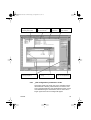
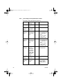
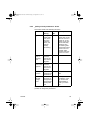
LS4soT-E.FM Seite 1 Dienstag, 28. August 2001 1:29 13
LS4Soft
Configuration and Diagnostics Software
for SIGUARD Laser Scanner LS4-4
User Manual
Order No.: 3RG7838-4CE
Technician Alienating
LS4so-E.book Seite 2 Donnerstag, 23. August 2001 7:18 19
GWA 4NEB 839 6063 02
50036436
LS4so-E.book Seite 1 Donnerstag, 23. August 2001 7:18 19
TABLE OF CONTENTS
1
About the User Manual ........................................................... 1
2
First Steps ............................................................................... 2
2.1
2.2
2.3
2.4
2.5
2.6
2.7
2.8
2.9
2.10
Foreword ............................................................................................... 2
Software Structure ................................................................................. 2
Required Components .......................................................................... 3
System Requirements ........ Software .................................................. 3
System Requirements ........ Hardware (PC) ......................................... 3
System Requirements ........ Hardware (Cables, Connectors) .............. 4
System Requirements / ....... Other ........................................................ 4
Interfaces and Pin Assignments for the SIGUARD
Laser Scanner LS4-4 ............................................................................ 4
Connecting the SIGUARD Laser Scanner LS4-4 .................................. 8
Installing the Software ........................................................................... 9
3
Calling Up LS4Soft and Starting the System ....................... 9
3.1
3.2
3.3
Establishing Communication from PC to LS4-4 .................................... 9
Startup Page with Verification of Safety-Relevant Parameters ........... 10
User Levels ......................................................................................... 11
4
Main Menu ............................................................................. 12
4.1
4.2
4.3
4.4
4.5
4.6
4.7
Menu Structure .................................................................................... 12
Main Menu Line ................................................................................... 12
Subject Line ......................................................................................... 13
Standard Buttons in the Function Line ................................................ 13
Information Field Line .......................................................................... 14
Coordinate Control and Display .......................................................... 15
Displaying Measurement Values and Fields in the Contour Area ....... 16
5
Display the measurement contour .... Subject Button ....... 18
5.1
Define the detection zone display ................ Function Button ............. 18
6
LS4 configuration ............................... Subject Button ....... 20
6.1
6.2
6.3
6.4
6.5
6.5.1
6.5.2
6.5.3
Load configuration data from a file ............... Function Button ............. 21
Save configuration data as a file .................. Function Button ............. 21
Retrieve configuration data from the LS4 ..... Function Button ............. 21
Transfer configuration data from PC to LS4 . Function Button ............. 22
Change configuration data ........................... Function Button ............. 22
„LS4 configuration parameters“ ................... folder ............................. 23
„Non-safety-critical parameters“ .................. folder ............................. 24
„Safety-critical parameters“ ......................... folder ............................. 25
- start interlock
- startup test
- Admissible field pair change-overs
- startup field pair
„Field pair 1 to 4" ......................................... folders ........................... 30
Set standard values for LS4 ......................... Function Button ............. 31
6.5.4
6.6
7.
Define detection zones/warning
fields..................................................... Subject Button ....... 33
7.1
7.2
7.3
7.4
7.5
Load detection zone/warning field from file .. Function Button
Save detection zone/warning field as a file .. Function Button
Select detection zone/warning field .............. Function Button
Enter detection zone/warning field ............... Function Button
Define elliptical detection zone/
warning field ................................................. Function Button
............. 34
............. 35
............. 35
............. 35
............. 36
LS4so-E.book Seite 2 Donnerstag, 23. August 2001 7:18 19
7.6
7.7
7.8
7.9
7.10
7.11
7.12
7.13
Define rectangular detection zone/
warning field .................................................Function Button .............36
Define polygonal detection zone/
warning field .................................................Function Button .............38
(freistehend) ........................................................................................39
Change detection zone/warning field
segment ........................................................ Function Button .............40
Limit detection zones/warning field...............Function Button .............41
Blanking out a detection zone/warning
field segment ................................................Function Button .............42
Delete detection zone/warning field..............Function Button .............44
Transfer detection zone/warning field
from PC to LS4 .............................................Function Button .............44
8
LS4 system data ................................. Subject Button ....... 46
8.1
8.2
8.3
8.4
Load system data from the LS4....................Function Button
Display LS4 error list ....................................Function Button
Calibrate window monitoring ........................Function Button
Reset LS4 .....................................................Function Button
.............46
.............46
.............47
.............47
9
Additional Functions on the Main Menu Line .................... 48
9.1
Menu „View“ ........................................................................................48
- Function „Save diagram as a file“
Menu „Settings“ ...................................................................................48
- Function „Interface“
- Function „Language“
- Function „Change diagram color“
- Function „190˚ detection zones and warning fields“
Menu „Detection zones/warning fields“ ...............................................49
- Function „Modified detection zones/warning fields“
Menu „Security“ ...................................................................................49
- Function „Change password“
- Function „Reset password“
Menu „Help“ .........................................................................................50
- Function „Info“
9.2
9.3
9.4
9.5
10
Additional Information and Summary ................................ 51
10.1
10.2
10.3
10.4
Initial Configuration ..............................................................................51
Changing a Scanner Configuration or Field Definition ........................52
Creating a Configuration Without a Connected Scanner .....................53
Replacing Devices ...............................................................................53
LS4so-E.book Seite 3 Donnerstag, 23. August 2001 7:18 19
LS4so-E.book Seite 4 Donnerstag, 23. August 2001 7:18 19
LS4so-E.book Seite 1 Donnerstag, 23. August 2001 7:18 19
1
About the User Manual
This documentation contains all information regarding proper
use of the configuration software LS4Soft. It is supplied with
every delivered system and is intended for use by the planners, operators and maintenance personnel of systems that
are safeguarded by the SIGUARD laser scanner LS4-4. The
documentation must be kept so that it is easily accessible at
all times.
Safety precautions and warnings are designated by the
symbol
.
Please verify that the LS4-4 laser scanner is installed and
mounted so as to be ready for operation as specified by
the Technical Description No. 3RG7838-4BE. Siemens AG
is not liable for damage resulting from improper use of its
equipment. Familiarity with these two manuals constitutes
part of the knowledge required for proper use.
The LS4Soft software was designed exclusively for the LS4
scanner series. The user manual was written with reference
to the SIGUARD laser scanner LS4-4 with a detection zone
range of 4 meters. For this reason, both designations (LS4-4
and LS4) are used in the text and in the illustrations.
Version of the contents: V1.01
© No reprints or duplications, in full or in part.
LS4Soft
1
LS4so-E.book Seite 2 Donnerstag, 23. August 2001 7:18 19
2
First Steps
2.1
Foreword
This manual describes the functional and performance
features of the LS4Soft software. LS4Soft is an extremely
powerful configuration and diagnostics software program
designed for use with the laser scanner SIGUARD laser
scanner LS4-4. During development, the highest priorities
were placed on reliability and user-friendliness. LS4Soft is
not suitable for configuring devices made by other manufacturers.
The organization of this user manual parallels the sequences
and hierarchies of the software menu points. The manual provides you with clear information regarding the structures and
functions of LS4Soft. Where more complex subjects are concerned, you can refer to the screen shot illustrations, which
give you a concrete look at the points under discussion. The
software itself offers an additional „help“ text for each function
button. Simply move the mouse pointer to a function button,
and a descriptive pop-up window will appear automatically.
Please keep this description in a safe place and make sure
that it is accessible during the entire service life of the software.
2.2
Software Structure
LS4Soft follows a subject-related tree structure:
2
•
The user interface was designed to be Microsoft® compatible as far as possible in order to shorten the learning
curve.
•
Subject buttons refer to function groups and the detailed
functions incorporated in them.
•
Function buttons enable desired functions to be performed; many of these buttons offer dialog boxes and
drop-down menus to simplify the selection process.
•
Standard buttons contain frequently required functions
and are not linked to any specific subject.
LS4Soft
LS4so-E.book Seite 3 Donnerstag, 23. August 2001 7:18 19
2.3
Required Components
The following components are required for the initial startup:
2.4
•
Laser scanner LS4-4, installed as specified in Technical
Description No. 3RG7838-4BE
•
PC or laptop with color monitor and installed LS4Soft
program
•
RS 232 interface cable (1:1, without cross-connection) or
RS 422 interface cable for the connection to X2 (see
Chapter 2.8)
•
Control cable (power supply, changeover, restart) for the
connection to X1 (see Chapter 2.8)
System Requirements / Software
Microsoft® Windows 95/98/NT®/2000
2.5
LS4Soft
System Requirements / Hardware (PC)
•
Intel® processor, Pentium® class or better (or compatible
models such as AMD® or Cyrix®)
•
At least 16 MB RAM
•
3 1/2’’ disk drive
•
Hard drive with at least 8 MB of free memory
You may need more disk storage if detection zone data
and/or configuration data are going to be stored.
•
Mouse
•
Free RS 232 serial interface, or alternatively, RS 422
interface
3
LS4so-E.book Seite 4 Donnerstag, 23. August 2001 7:18 19
2.6
2.7
System Requirements / Hardware (Cables,
Connectors)
•
Wire cross-section of cable X1: at least 0.5 mm2
•
Outer diameter of the cable: between 5 mm and 10 mm
•
Maximum cable length X1: 50 m
•
Maximum cable length X2: 10 m for RS 232
•
Maximum cable length X2: 50 m for RS 422
•
Use shielded cables
•
Use only the LS4-MG connectors and the LS4-MG cover
provided with the delivered system.
System Requirements / Other
•
Printer (black-and-white or color)
Please refer to Chapter 4.2 in the Technical Description of the
SIGUARD laser scanner LS4-4.
2.8
4
Interfaces and Pin Assignments for the
SIGUARD Laser Scanner LS4-4
Interface No.
Interface
Type
Interface Function
X1
SUB-D15
Connections for:
• Power supply
• Switch and signal cables
X2
SUB-D9
Interface SIGUARD laser
scanner LS4-4 - PC
• Parameter configuration
• Detection zone and warning
field definition
• Data transfer
• Diagnostics
LS4Soft
LS4so-E.book Seite 5 Donnerstag, 23. August 2001 7:18 19
Pin assignments for interface X1
FP 4 8
FP 3 7
FP 2 6
Alarm 5
FP 1 4
UB 3
Restart 2
15 Reserved
14 NC
13 NC
12 OSSD2
11 OSSD1
10 NC
9
NC
GND 1
Pin assignments for interface X2 used as an RS 232 port
1
TxD 2
RxD 3
4
6 RS232 recognition
7 NC
8 NC
9 Reserved
GND/ 5
shield
Pin assignments for interface X2 used as an RS 422 port
Tx- 1
Tx+ 2
Rx+ 3
Rx- 4
GND/ 5
shield
Fig. 1
LS4Soft
6 RS422 recognition
7 NC
8 NC
9 Reserved
Connection of
PIN 5 to PIN 6
Interface pin assignments with a view to the
SIGUARD laser scanner LS4-4
5
LS4so-E.book Seite 6 Donnerstag, 23. August 2001 7:18 19
PIN Signal
Description
1
GND
Ground for the supply voltage
2
Restart
Input, scanner reset, and connecting the
RESTART button
3
UB
Supply voltage +24 VDC
4
FP 1
Changeover to field pair 1
5
Alarm
Semiconductor output that switches off
when the warning field is violated as well
as for warning messages such as „window
slightly dirty“, error messages such as
„window very dirty“, and for internal errors
(the functions can also be selected in
combination).
6
FP 2
Changeover to field pair 2
7
FP 3
Changeover to field pair 3
8
FP 4
Changeover to field pair 4
9
NC
Not connected
10
NC
Not connected
11
OSSD 1
Semiconductor output, switches off when
the detection zone is violated, Channel 1
12
OSSD 2
Semiconductor output, switches off when
the detection zone is violated, Channel 2
13
NC
Not connected
14
NC
Not connected
15
Reserved
Reserved for testing purposes, no wiring
Pin Assignments for Connector X1
A field pair consists of one detection zone and one warning
field.
6
LS4Soft
LS4so-E.book Seite 7 Donnerstag, 23. August 2001 7:18 19
PIN
Signal
Description
1
NC
Not connected
2
TxD
Data communication, transmit
3
RxD
Data communication, receive
4
NC
Not connected
5
GND /
shield
Ground / shield (connect with PE to the
electronics cabinet only)
6
RS 232
Not connected
7
NC
Not connected
8
NC
Not connected
9
Reserved
Reserved for testing purposes,
no wiring
Pin Assignments for Connector X2 used as an RS 232 Port
PIN
Signal
Description
1
TxD-
RS 232/ RS 422 transmitted data
2
TxD+
3
RxD+
4
RxD-
5
GND /
shield
Ground / shield (connect with PE to the
electronics cabinet only)
6
RS 422
Select RS 422 interface by connecting
a bridge to pin 5
7
NC
Not connected
8
NC
Not connected
9
Reserved
Reserved for testing purposes,
no wiring
RRS 232/ RS 422 received data
Pin Assignments for Connector X2 used as an RS 422 Port
LS4Soft
7
LS4so-E.book Seite 8 Donnerstag, 23. August 2001 7:18 19
2.9
Connecting the SIGUARD Laser Scanner LS4-4
To configure the scanner, connect the control cable (X1) to
the power supply (safety transformer 24 V, 2.5 A, 1.25 A
semi-delay fuse) and the interface cable (X2) to the PC or
laptop. Before starting up the system, please verify the connector assignments, the wiring, the supply voltage and the
fuse protection. Although the scanner is robustly constructed
and equipped with various internal safety mechanisms, it is
possible that damage could be caused by faulty wiring.
For further information, consult the Technical Description of
the SIGUARD laser scanner LS4-4 (Chapter 4.2).
PIN
1
2
3
4
5
6
7
8
9
10
11
12
13
14
15
a
Signal
GND
Restart
UB
FP 1
Alarm
FP 2
FP 3
FP 4
NC
NC
OSSD 1
OSSD 2
NC
NC
Reserved
d
b
c
STOP
a
b
c
d
8
ok.
ok.
=
=
=
=
Connection for setting parameters only
Dummy connector
Connector X1 (15-pin, SUB-D)
Connector X2 (9-pin, SUB-D)
LS4Soft
LS4so-E.book Seite 9 Donnerstag, 23. August 2001 7:18 19
2.10 Installing the Software
Place diskette #1 into the appropriate disk drive.
Start the installation program Setup.exe. After selecting the
desired language (German or English) you will be asked for
the installation path. The folder „Siemens AG“ is recommended. Confirm the entries. Now you can load the program
successively using the diskettes. Once this process is completed, LS4Soft is ready for operation.
To enable the program to be called up faster, use the
Microsoft® function „Create shortcut” to add the LS4Soft
icon to the desktop.
LS4Soft
3
Calling Up LS4Soft and Starting the
System
3.1
Establishing Communication from PC to
LS4-4
•
Start the software by double-clicking either on
„LS4_hmi.exe“ or on the desktop icon. For a few seconds
you will see the software startup page indicating the
version number. Then the main menu appears with a
dialog box for selecting the authorization level (see
Chapter 3.2).
•
Apply the supply voltage to the SIGUARD laser scanner
LS4-4. The scanner will now automatically attempt to
communicate with your PC.
•
Once the PC and scanner have been successfully
synchronized, the text in the info field changes from
„LS4 sync“ to „LS4 connect“.
•
The current configuration of the LS4-4 is transferred to the
PC. A progress bar on the screen shows the configuration
data being loaded.
•
Please replace the standard passwords with individual
passwords. A request to this effect will appear on the
screen (see Chapter 3.3 and 9.4).
9
LS4so-E.book Seite 10 Donnerstag, 23. August 2001 7:18 19
3.2
10
Startup Page with Verification of SafetyRelevant Parameters
•
The LS4 configuration and the status information are now
automatically transferred and displayed. Please compare
these safety-relevant data with the parameters required
for the current application.
•
After you close the dialog box, you can begin configuring
the scanner.
LS4Soft
LS4so-E.book Seite 11 Donnerstag, 23. August 2001 7:18 19
3.3
User Levels
To ensure that the device configuration is performed only by
trained and authorized personnel, LS4Soft uses the dialog
„Change authorization level“ to distinguish among various
authorization levels providing access to various ranges of
function. The following levels are available:
Level
Info
Field
Password Access to Functions
Operator
(Be)
---
General settings, display
and evaluation of measurement values, transferring configuration data
from LS4-4 to PC, no
changes to the system
configuration
Maintenance
(In)
SIGUARD
Device configurations can
be loaded from diskette
and saved in the LS4-4.
It is not possible to make
changes to the parameters
themselves.
Autho(AK)
rized
customer
LS4SIG
Complete access to all
user-related functions and
parameters.
Service
(Se)
WINCALIB Access to the scanner window calibration function for
trained personnel
Production
(Fe)
---
Manufacturer-specific
access
Development
(En)
---
Manufacturer-specific
access
The factory-preset password for the authorized customer/
safety official (AK) is „LS4SIG“. During the initial configuration
of the SIGUARD laser scanner LS4-4, the safety official must
select and save new passwords for (In) and (AK); the (electronic or hard-copy) carrier of this information must be kept
locked up in a secure location. Each password can be
entered using either upper-case or lower-case letters; the
password acceptance is not case-sensitive. Since the
LS4Soft
11
LS4so-E.book Seite 12 Donnerstag, 23. August 2001 7:18 19
authorization level „Operator“ does not allow any changes
to be made to the device configuration, it is not password-protected. After the authorization level has been determined, all
inaccessible function buttons are disabled and colored light
gray.
In order to access the service (Se) level, you need both the
correct password and a security diskette. For further information, see Chapter 9, „Additional Functions on the Main Menu
Line“.
4
Main Menu
4.1
Menu Structure
The main menu displays the measured contours and detection zones. It also features subject-related menu control and
additional information fields. This is a very user-friendly
method for changing the operating mode and for accessing
many different dialogs and functions without losing track of
what is going on. After selecting one of the four subject buttons, you can choose from relevant function buttons offering
related selection boxes and drop-down menus. This method
for guiding the operator is used throughout the program.
4.2
Main Menu Line
This line contains the complete catalog of available functions.
12
LS4Soft
LS4so-E.book Seite 13 Donnerstag, 23. August 2001 7:18 19
4.3
4.4
Subject Line
•
„Display the measurement contour“ button
Measurement mode is activated; the current detection
zone and warning field are shown in red and green,
respectively. Additional programmed fields can be
selected individually by means of a dialog (e.g. reference
display).
•
„LS4 configuration“ button
All functions required for configuring the scanner are
available here.
•
„Define detection zones/warning fields“ button
This subject area allows you to create application-specific
definitions of the four detection zones and the four warning fields using either the mouse or numerical input.
•
„LS4 system data“ button
This subject area contains data for identifying the device
and diagnosing errors.
Standard Buttons in the Function Line
Frequently required functions are available at all times in the
function line below the subject buttons.
LS4Soft
•
Zooming (enlarge or reduce picture, total view of 80 x
140 m)
•
Change authorization level
•
Display PC error list (list of PC-related errors with date
and time)
•
End configuration program
13
LS4so-E.book Seite 14 Donnerstag, 23. August 2001 7:18 19
4.5
Information Field Line
You can find information regarding the operating mode and
the current authorization level in the information line at the
very bottom of the screen as follows (from left to right):
•
•
•
•
14
Current data communication between PC and LS4-4
-
„LS4 sync“
for synchronizing the communication between scanner and
PC
-
„LS4 connect
„when the data transfer
connection is established
Operating status of the scanner
-
„LS4 > Measurement operation“ shows that the
scanner is actively recording
measurement data
-
„LS4 > Configuration „shows that configuration data
are being transferred with the
OSSDs switched off
-
„LS4 > Error“
signals a system error with the
OSSDs switched off
Selected subject button of the user program
-
„Display the measurement contour„
-
„LS4 configuration“
-
„Define detection zones/warning fields“
-
„LS4 system data“
Field status
-
Detection zone and warning field violated/switched off
– indicators SF and WF are red
-
Warning field violated – indicator WF is green
-
Detection zone and warning field clear – no indicator
LS4Soft
LS4so-E.book Seite 15 Donnerstag, 23. August 2001 7:18 19
•
•
4.6
Current access level
Depending on the setting, the following abbreviations are
displayed:
-
Be
for operator
-
In
for maintenance
-
AK
for authorized customer
-
Se
for service (no standard access)
-
Fe
for production (no access)
-
En
for development (no access)
Further messages and functions (below the contour field)
include:
-
Name of the currently active field pair, numbered from
1 to 4
-
Field pairs displayed on the screen, numbered from 1
to 4, according to the selection in the selection dialog
-
Current source of data (LS4/file)
-
X/Y coordinates for the numerical display of the
mouse pointer position (see Chapter 4.6)
-
Positioning of the contour field and optimization of
display (see Chapter 4.6)
Coordinate Control and Display
In this part of the menu, located at the bottom right, the Xand Y-coordinates are displayed while the fields are being
defined. In measurement mode, the position of the mouse
pointer is displayed. Or, if a detection zone contour has been
clicked on and dragged into position, this will be displayed.
This feature makes it easy to localize objects and to create a
detailed representation of particular areas.
To the right, next to the coordinate display, are arrow buttons
for selecting the image area of the detection zones and warning fields and the section of the measurement contour that
you want to be displayed. A very convenient function is
located behind the centering point. When you click here,
the detection zone, warning field and measured contour will
LS4Soft
15
LS4so-E.book Seite 16 Donnerstag, 23. August 2001 7:18 19
be ascertained and automatically displayed on the screen on
their entirety. This feature gives you a quick overview of the
field proportions.
4.7
Displaying Measurement Values and Fields in
the Contour Area
The following color assignments are used to make it easier to
differentiate among the various contours:
Contour
Color
Minimum detection zone
blue
Detection zone
red
Warning field
green
Measured contour
yellow / red
Selected mouse pointer area
yellow
Deactivated detection zone
light gray
Deactivated warning field
dark gray
Mouse pointer
dark blue
The information block in the main menu, bottom left, shows
the display of the active field pairs as well as the field pairs
selected for display.
16
LS4Soft
LS4so-E.book Seite 17 Donnerstag, 23. August 2001 7:18 19
Subject
buttons
Information
field line
LS4Soft
Function
buttons
Standard
buttons
Information
block
Detection zone
and warning field,
inactive
Main menu
line
Detection zone, red, active
Warning field, green, active
Measurement contour, yellow
Function
line
Coordinate
display
Subject
line
Contour field
positioning
17
LS4so-E.book Seite 18 Donnerstag, 23. August 2001 7:18 19
5
Display the measurement contour,
Subject Button
This menu allows you to select the active and inactive detection zones and warning fields to be displayed as well as the
measured contour of the room. Using constant comparisons,
the SIGUARD laser scanner LS4-4 ascertains the distance
from the measured room contour to the detection zone and
provides these data to the PC. If the measured contour
penetrates the previously defined detection zone during a
violation of the detection zone, the color of the measured
contour in this area changes from yellow to red.
5.1
Define the detection zone display, Function
Button
Click on the button „Define the detection zone display“ to call
up a dialog box for selecting the field pairs to be displayed.
Active field pairs appear in red/green, and inactive field pairs
in shades of gray.
No field pair needs to be selected for a neutral contour display
(e.g. for a printout). As soon as a field is selected under
„Define detection zones/warning fields“ (subject button), or a
field pair is selected by way of control cable X1, the selected/
activated field pair appears on the screen again in red/green.
18
LS4Soft
LS4so-E.book Seite 19 Donnerstag, 23. August 2001 7:18 19
Function buttons, as
described above
Information block regarding the active and displayed
field pairs
LS4Soft
Dialog box for selecting
the field pair display
Display of the
field violation
Inactive field
pair 4
Detection zone violation
with a change in color
of the measured contour
Measured
contour
Active field
pair 1
19
LS4so-E.book Seite 20 Donnerstag, 23. August 2001 7:18 19
6
LS4 configuration, Subject Button
Select this menu to choose the functions for configuring the
SIGUARD laser scanner LS4-4.
This subject area comprises data transfer as well as safetyrelevant and non-safety-relevant parameter settings of the
scanner.
Since this menu involves points relevant to safety, please
note that access is possible only when the appropriate password is entered.
Function buttons,
as described
below
20
Catalog of previously
saved scanner
configurations
File name
entry
Date and time
of the last
change
Confirmation
of dialog
entries
LS4Soft
LS4so-E.book Seite 21 Donnerstag, 23. August 2001 7:18 19
6.1
Load configuration data from a file, Function
Button
Click on this button to open a dialog box providing an overview of the scanner configurations that are already saved in
the PC. Enter and/or confirm the path and file name. Click on
the button „Open“ to confirm your selection, and the desired
configuration will be called up. For a detailed description of
the contents of the configuration data, see the section
„Change configuration data“, Chapter 6.5.
6.2
Save configuration data as a file, Function
Button
Click on this button to open a dialog box that allows you to
save the currently defined scanner configuration. Enter and
confirm the path and file name. During the storage process, a
progress bar with a confirmation message appears on the
screen.
For a detailed description of the contents of the configuration
data, see the section „Change configuration data“, Chapter
6.5.
6.3
Retrieve configuration data from the LS4,
Function Button
Click on this button to load the configuration data from the
LS4-4 onto the PC. These data can be subjected to further
processing or revised, if desired, by personnel with the
required authorization. During loading, a progress bar with
a confirmation message appears on the screen.
For a detailed description of the contents of the configuration
data, see the section „Change configuration data“, Chapter
6.5.
LS4Soft
21
LS4so-E.book Seite 22 Donnerstag, 23. August 2001 7:18 19
6.4
Transfer configuration data from PC to LS4,
Function Button
Click on this button to load the configuration data from the PC
onto the LS4-4 and to save the configuration data. During the
loading and saving process, a progress bar with a confirmation message appears on the screen.
The information received by the LS4-4 will now be transferred
back as echo data and displayed on the screen so that the
safety official can confirm the transfer.
CAUTION! Since the PC is not a safety product and computer-specific errors can occur, the echo data transmitted by
the LS4-4 must be checked for errors and confirmed by an
authorized person.
For a detailed description of the contents of the configuration
data, see the section „Change configuration data“, Chapter
6.5.
6.5
Change configuration data, Function Button
Click on this button call up a two-part dialog for changing
safety-relevant and non-safety-relevant parameters as well
as data related to the detection zone. These system-specific
data can be converted automatically into a .txt format and
then printed out.
22
LS4Soft
LS4so-E.book Seite 23 Donnerstag, 23. August 2001 7:18 19
Data regarding detection zones
and warning fields (folder)
Save the data in .txt format for
a subsequent printout
Parameters belonging to
the selected folder
Set value of
parameters
Time of the configuration
change
Parameter-related
status indicator
Input field corresponding
to the selected parameters
6.5.1 „LS4 configuration parameters“ folder
This folder contains the check sum of the complete configuration data file. Following a data transfer, for instance, this
sum is compared with the newly calculated check sum. If a bit
was falsified during the data transfer, the two sums will no
longer agree and an error message will appear.
LS4Soft
23
LS4so-E.book Seite 24 Donnerstag, 23. August 2001 7:18 19
6.5.2 „Non-safety-critical parameters“ folder
This folder contains the following functions:
24
Parameter
Function /
Setting
Status
Possible entries
LS4 name
Scanner
name
*
As desired
Additional
description
Description of
the application
*
As desired
Output
start segment
Screen display of the first
contour segment
*
0 to 528 segments
• 0 to 528 segments
corresponds to
190°
• 14 to 514 segments corresponds to 180°
Output
stop segment
Screen display of the last
contour segment
*
0 to 528 segments
• 0 to 528 segments
corresponds to
190°
• 14 to 514 segments corresponds to 180°
Output
resolution
Number of
measurement values
per display
interval. The
lowest value
in each interval is displayed.
*
1 to 50 consecutive
measurements
Serial interface
Change in
baud rate
*
4800 to 115,200
baud
Alarm
signaling
type
Switches off
the alarm
output
*
Optionally for an
error message, a
violation of the
warning field, or
both
LS4Soft
LS4so-E.book Seite 25 Donnerstag, 23. August 2001 7:18 19
6.5.3 „Safety-critical parameters“ folder
This folder contains the following functions:
Parameter
Function /
Setting
Status
Input Options
Application
Settings for
restart interlock, detection zone
response
times, and
scanner
startup
functioning
*
The detection zone
restart time can be
set from 160 ms to
10160 ms, or the
restart can be performed manually.
Detection zone
and warning field
response time from
80 ms to 640 ms
possible. Start
interlock and startup test or no test.
Measurement of
start segment
Technical
measurement of the
first contour
segment
R
---
Measurement of stop
segment
Technical
measurement of the
last contour
segment
R
---
Dust suppression
Optimizes
*
freedom from
interference
Admissible
field pair
changeovers
Determines
sequence of
changeovers
as well as the
startup field
pair
*
Activate or deactivate
Two input fields are
provided by a dialog. Click on the
desired fields to
make your selection.
In the status field, R means „read only“ and * means it is
possible to change the parameters.
LS4Soft
25
LS4so-E.book Seite 26 Donnerstag, 23. August 2001 7:18 19
Changing the parameters described above has no effect on
the number of measurements taken or on the effectiveness of
the defined detection zones.
Additional Information (non-safety-critical parameters):
•
Start and stop segments:
The output setting of the start and stop segments is used,
for example, for contour measurement (e.g. 20˚ sections).
This allows an individual, limited display of partial sections. Modifying these values merely changes the display
of the contours on the screen; the number of measurements taken remains the same. This reduces both the
amount of data and the transfer time.
•
Output resolution:
A mean value for the display can be selected regardless
of the number of measurements taken. If „15“ is entered,
for example, the lowest value within each interval of 15
measurement points is plotted, and these successive
values are used to create a line graph. Using this function
results in a smoother display of the contours. For a
detailed display, use setting „1“.
Additional Information (safety-critical parameters):
•
26
Application:
Standardized parameter settings for safeguarding areas
and safeguarding automatic guided vehicles (AGVs) are
provided in a dialog.
LS4Soft
LS4so-E.book Seite 27 Donnerstag, 23. August 2001 7:18 19
Application
Parameter
Selection
Factory
Setting
Safeguarding an area
Startup type
Start interlock
Startup test
No test
Manual
80 ms
640 ms
x
Start interlock
Startup test
No test
2s
80 ms
640 ms
x
Restart
SF/WF response time
AGV
Startup type
Restart
SF/WF response time
Select the configuration block
LS4Soft
Display the selected
parameters
Dialog for selecting the
standardized parameter
blocks
x
x
x
x
Display of the parameters
waiting to be activated
27
LS4so-E.book Seite 28 Donnerstag, 23. August 2001 7:18 19
When start interlock is active, the safety outputs of the
LS4-4 (OSSD 1 and OSSD 2) will not be enabled or switched
„active high“, even if the current detection zone is clear, until
the RESTART button has been actuated for a period of 2 to
4 seconds (24 V to pin 2 of interface X1).
When startup test is active, after the scanner has been
switched on, the safety outputs of the LS4-4 (OSSD1 and
OSSD2) will not be enabled or switched „active high“, even
if the current detection zone is clear, until the detection zone
is temporarily violated one time.
When restart interlock is active, the safety outputs
(OSSD 1 and OSSD 2) of the LS4-4 will not be enabled or
switched „active high“, even if the current detection zone is
clear, until the RESTART button has been actuated for a
period of 2 to 4 seconds (24 V to pin 2 of interface X1). This
function is active after every violation of the detection zone.
The dust suppression function of the SIGUARD laser scanner LS4-4 is a software function for increasing the availability
of the laser scanner in the presence of dirt or small particles
in the air, such as insects. If dust suppression is activated, a
somewhat larger addition to the detection zone contour must
be made. With or without dust suppression, and with a detection zone radius of up to 3.5 m, the addition has a value of
81 mm. With activated dust suppression and a detection zone
radius of 3.5 m or more, the addition has a value of 98 mm.
The addition is shown in the echo data.
Please refer to Chapter 7 for information on defining detection
zones when the dust algorithm is active.
Due to its four freely programmable field pairs, the SIGUARD
laser scanner LS4-4 can be used very flexibly in a wide range
of applications. The selected detection zones are checked for
plausibility when the admissible changeover sequence is
chosen in the dialog „Admissible field pair changeovers“.
Inadmissible changeover sequences are detected and cause
the OSSDs to be switched off. Furthermore, each field pair
can be defined as the system startup field pair.
These features are useful with automatic guided vehicles, for
instance, when the detection zone is changed over to accommodate straight and curved routes and when the vehicle
starts up in a straight section.
28
LS4Soft
LS4so-E.book Seite 29 Donnerstag, 23. August 2001 7:18 19
Function button
"Change configuration
data"
Path within RS4soft
(from left to right)
Matrix for determining
admissible field pair
changeovers
Matrix for determining
admissible startup
field pairs
After the scanner configuration has been entered, it must be
transferred to the LS4; to do so, click on the function button
„Transfer configuration data from PC to LS4“. If you forget to
do this, the transfer dialog is automatically called up before
another subject button can be selected. Due to the safe protocol, you can now view and confirm the echo data reflected
by the scanner.
CAUTION! Since the PC is not a safety product and computer-specific errors can occur, the echo data transmitted by
the LS4-4 must be checked for errors and confirmed by an
authorized person.
LS4Soft
29
LS4so-E.book Seite 30 Donnerstag, 23. August 2001 7:18 19
Display of RS4
echo data
Configuration
parameters
Selected
setting
Confirmation
button
If the echo data are returned accurately, you must confirm the
record by pressing the button „Accept“. Changing a configuration can require that the detection zones be checked again.
For information on the echo data, please refer to Chapter
7.13.
6.5.4 „Field pair 1 to 4" folders
Double-click on the folders to select the subfolders „detection
zone“ and „warning field“. Selecting one of these subfolders
causes field-specific data to appear in the right-hand section
of the dialog box: name of the field, date and time of the latest
change, field status, and information on admissible field pair
changeovers. In addition, the minimum object width is stated
with respect to the number of segments (x * 0.36˚). This
means that the lateral value in millimeters is dependent upon
the maximum radius of the field contour.
30
LS4Soft
LS4so-E.book Seite 31 Donnerstag, 23. August 2001 7:18 19
6.6
Set standard values for LS4, Function Button
This function allows you to reinstate the factory-set configuration (delivery state) of the SIGUARD laser scanner LS4-4.
As an alternative to this function button, you can also press
the RESTART button (press pins 2 and 3 on connector X1)
before switching on the scanner. Release the button after
approx. 2 seconds; LEDs 2, 3 and 5 will be lit up in the
scanner display. This means that the scanner has been reset.
The table below describes the resultant setting:
LS4Soft
Parameter
Value
Parameter
Value
Detection
zone range
4m
Application
Safeguarding an area
Detection
zone display
190°
Restart
Manual
Detection
zone response time
80 ms
Restart when
reset
Activated
restart
interlock
Field pair
changeover
No
changeover
Startup type
None
Startup field
pairs
1, 2, 3, 4
Dust algorithm
Activated
Detection
zone name
---
Start segment output
0
Warning field
range
5m
Stop segment
output
528
Warning field
display
190°
Baud rate
57600 bd
Warning
field, response time
80 ms
Name of the
scanner
---
Alarm signaling type
Violation of
the warning field
Description of
the scanner
---
31
LS4so-E.book Seite 32 Donnerstag, 23. August 2001 7:18 19
Please note that the reset function described above may not
be repeated for a period of 2 minutes.
After determining the scanner configuration, the setting must
be documented in suitable form at the monitored machine or
system. You need to generate a text file of the configuration
for this purpose.
The button „Generate text file“ allows you to do this. Clicking
on this button initiates a dialog for entering the file name and
converts the data into .txt format. To make a printout, open
the file (e.g. „LS4-4.txt“) in a word processing program such
as MS-Word® and click on the Print button.
The following information appears on the printout:
•
Date, user, data source
•
Scanner serial number, device type, software version
•
Non-safety-critical parameters
•
Safety-critical parameters
•
Information on the detection zones and warning fields of
all four field pairs
Read Chapter 9.1 to find out how to print out a detection zone
contour.
32
LS4Soft
LS4so-E.book Seite 33 Donnerstag, 23. August 2001 7:18 19
7.
Define detection zones/warning fields,
Subject Button
This menu provides you with extensive possibilities for defining detection zones.
These include transferring data as well as creating and
modifying the detection zones (for detecting the presence
of personnel) and warning fields. Since this area involves
safety-relevant functions of the scanner, access is possible
only when the appropriate password is entered.
The smallest section of a detection zone must cover a lateral
distance of at least 3.5 cm. When defining detection zones,
make sure that no pin-shaped contours are set, as these do
not provide a guaranteed safety effect.
The maximum selectable detection zone radii vary depending
on the type of contour:
SIGUARD Laser
Scanner LS4-4
Range
Factory Setting
Detection zone
4m
4m
Warning field
15 m
5m
Contour measurement
50 m
---
The scanner is factory-programmed with semicircular detection zones (190˚) which will be in effect after the initial startup.
Please note that only detection zones (SF), and not warning
fields (WF), may be used for the performance of safetyrelated tasks.
LS4Soft
33
LS4so-E.book Seite 34 Donnerstag, 23. August 2001 7:18 19
Load or save detection
zone/warning field data
Field catalog
Choose the basic
contours of the detection
zone/warning field
Base point of the X and Y coordinates
with the left and right field pair half
7.1
Tools for modifying the
basic contours
Factory-set detection
zones and warning fields
Data transfer
to the scanner
Optimizing
the display
Load detection zone/warning field from file,
Function Button
Click on this button to open a dialog box that will give you an
overview of the field configurations already saved on the PC
after you have entered the appropriate path and the file name.
You can call up the desired configuration (file extension „.sf“)
using the button „Open“ to make and confirm your selection.
See Chapter 7.13 for information on transferring the data.
34
LS4Soft
LS4so-E.book Seite 35 Donnerstag, 23. August 2001 7:18 19
7.2
Save detection zone/warning field as a file,
Function Button
Click on this button to open a dialog box that allows you to
save the previously defined field configuration. Enter the path
and the file name. Click on the button „Save“ to confirm your
entry, and the configuration will be saved as an .sf file.
7.3
Select detection zone/warning field, Function
Button
When you click on this drop-down menu, all eight fields
(4 detection zones and 4 warning fields) will be displayed for
you to select. Use the mouse to click on the field pair you want
to define. The current contours of the detection zone and
warning field will be shown in red and green, respectively.
Unselected field pairs appear in gray/light gray.
7.4
Enter detection zone/warning field, Function
Button
Click on this button to open a dialog box for numerically
entering the dimensions of the detection zone/warning field
in millimeters. You can enter dimensions for the front, left and
right edges of the zone/field to be defined. Confirm the edge
dimensions. These will then be displayed on the screen in the
appropriate color (detection zone in red, warning field in
green).
Please refer to the subpoint „190˚ field pairs“ in Chapter 9.2 .
LS4Soft
35
LS4so-E.book Seite 36 Donnerstag, 23. August 2001 7:18 19
7.5
Define elliptical detection zone/warning field,
Function Button
When you click on this button, all of the tools except Zooming
appear against a light gray background.
The program now waits for you to position the mouse pointer
and set the coordinates for the elliptical contour. You can
freely change the elliptical contour in the X- and Y-directions
as long as you keep the right mouse button pressed within
the contour field. The coordinate display is useful in helping
you check the dimensions as you set them. When you have
finished demarcating the field, release the right mouse
button. The set mouse pointer marks the intersection of the
horizontal and vertical line going to each side of the ellipsis.
Equivalent sections of the field are always generated in the
left and right halves of the display; these sections can be
modified separately at a later point in time.
Please refer to the subpoint „190˚ field pairs“ (see Chapter
9.2).
7.6
Define rectangular detection zone/warning
field, Function Button
When you click on this button, all of the tools except Zooming
appear against a light gray background.
The program now waits for you to position the mouse pointer
and set the coordinates for the rectangular contour. You
can freely change the rectangular contour in the X- and Ydirections as long as you keep the right mouse button
pressed within the contour field. The coordinate display is
useful in helping you check the dimensions as you set them.
When you have finished demarcating the field, release the
right mouse button. The set mouse pointer marks the corner
point of the horizontal and vertical line of the rectangle contour. Equivalent sections of the field are always generated in
the left and right halves of the display; these sections can be
modified separately at a later point in time.
Please refer to the subpoint „190˚ field pairs“ (see Chapter
9.2).
36
LS4Soft
LS4so-E.book Seite 37 Donnerstag, 23. August 2001 7:18 19
Detection zones
and warning
fields, 1 to 4 each
X-line/Y-line intersection - defined
using the button "Define elliptical
detection zone/warning field"
Distinguishing between the left and right field
pair halves using a plus or minus sign
Defined using the button
"Define rectangular detection
zone/warning field"
Field pair center line
Selection of
five basic field
contours
Coordinates of
the mouse pointer
A minus sign preceding the mouse pointer coordinates
designates the left half of the field pair, or the area below the
scanner zero axis.
LS4Soft
37
LS4so-E.book Seite 38 Donnerstag, 23. August 2001 7:18 19
7.7
Define polygonal detection zone/warning
field, Function Button
When you click on this button, all of the tools except Zooming
appear against a light gray background.
The program now waits for you to position the mouse pointer.
Click on the right-hand mouse button to „draw“ the contour of
the polygon point for point. The points along the contour are
always entered clockwise from left to right. As long as the
mouse button remains pressed within the contour field, you
can freely shift the current line segment in the X- and Y-directions. The coordinate display is useful in helping you check
the dimensions as you set them. Once you release the mouse
button, the process is complete and the line is set. Beginning
with the first point set by the mouse pointer, one line segment
is added to the contour with every click of the mouse button.
When the contour is complete, simply press the right-hand
mouse button.
Please refer to the subpoint „190˚ detection zones“ (Chapter
9.2).
38
LS4Soft
LS4so-E.book Seite 39 Donnerstag, 23. August 2001 7:18 19
Button for
e.g. 1st, 2nd, 3rd and
activating the
4th mouse click for
polygon function the current field
7.8
LS4Soft
End point set by
Displayed deactivated
clicking the right mouse
detection zone and
warning field (gray scale) button
Measured
contour
(freistehend)
39
LS4so-E.book Seite 40 Donnerstag, 23. August 2001 7:18 19
7.9
Change detection zone/warning field
segment, Function Button
Once a contour is specified, it can be modified by setting two
coordinate points with respect to the beam axis. When you
click on this button, all of the tools except Zooming appear
against a light gray background. The program now waits for
you to position the mouse pointer and click, thereby setting
the coordinates for the two coordinate points. Use the coordinate display to check your selection. The section of the contour between the points is a line showing the connections to
the previous contour. The connection itself follows the beam
axis. After you have set the first corrective point, the program
provides you with a yellow auxiliary line as a reference.
40
LS4Soft
LS4so-E.book Seite 41 Donnerstag, 23. August 2001 7:18 19
Button for activating the segment
change (example: function active)
Connective lines following
the beam axis
Sample contour
for comparison
Auxiliary line
(beam axis)
First and second
coordinate point
7.10 Limit detection zones/warning field, Function
Button
Click on this button to open a dialog box that allows you to
limit the dimensions of the field by making a numerical input
in millimeters. This refers to the front, left and right edges of
the field. After you confirm the edge dimensions, the limited
contour will be displayed.
LS4Soft
41
LS4so-E.book Seite 42 Donnerstag, 23. August 2001 7:18 19
Limiting measures to be
specified in the dialog
Button for activating
the segment limitation
Limited
contour
Sample contour
for comparison
7.11 Blanking out a detection zone/warning field
segment, Function Button
Once a contour is specified, you can blank out segments of
the detection zone by setting two coordinate points. The
segments between these two points will be blanked out.
When you click on this button, all of the tools except Zooming
appear against a light gray background.
The program now waits for you to position the mouse pointer
and click, thereby setting the coordinates for the beginning
and the end of the segment to be blanked out. The section of
42
LS4Soft
LS4so-E.book Seite 43 Donnerstag, 23. August 2001 7:18 19
the contour between the points is blanked out in the direction
of the beam axis. After you have set the first corrective point,
the program provides you with a yellow auxiliary line as a
reference. The coordinate display is useful in helping you
check your setting of the blanked out area.
Button for activating
the segment change
Sample contour
for comparison
First and second
coordinate point
Auxiliary line
(beam axis)
Connective line following
the beam axis
If you blank out sectors that can be entered or walked
through, hazards to personnel can result if the minimum
safety distance is no longer met. Additional measures must
be taken to safeguard the danger zone in such cases.
LS4Soft
43
LS4so-E.book Seite 44 Donnerstag, 23. August 2001 7:18 19
7.12 Delete detection zone/warning field, Function
Button
If you select this function, the detection zone definitions and
warning field definitions are replaced by the factory settings
(4 m radius for the detection zone, 5 m radius for the warning
field).
7.13 Transfer detection zone/warning field from
PC to LS4, Function Button
Click on this button to open a dialog box that gives an overview of the previously changed zone/field contours. This list
allows you to select the zones/fields that you want to be transferred to the LS4-4.
Once the dialog has been confirmed, the loading/saving
process begins and a progress bar appears on the screen.
The SIGUARD laser scanner LS4-4 sends the information it
received back to the PC as echo data so that the data transfer
can be verified. The transferred detection zone contours appear in a dialog; the contours must be checked and the dialog
must be acknowledged accordingly. After the check sums
have been recalculated, the transfer is concluded with an OK
message.
CAUTION! Since the PC is not a safety product and computer-specific errors can occur, the echo data transmitted by
the LS4-4 must be checked for errors and confirmed by an
authorized person.
44
LS4Soft
LS4so-E.book Seite 45 Donnerstag, 23. August 2001 7:18 19
Number of the
detection zone
Echo
dialog
Echo data contour
Registered maximum
values of the detection
zone
Automatically determined
detection zone addition
Date when admissible FP
changeovers were saved
Detection zone
to be transferred
The echo data contain the detection zone contours, the
maximum dimensions, the detection zone number, the date
and time they were saved, the admissible detection zone
changeovers, and the display of the detection zone addition.
The latter point must first be considered by the user when
defining the detection zones. For instructions on how to do
this, refer to the Technical Description of the SIGUARD laser
scanner LS4-4.
LS4Soft
45
LS4so-E.book Seite 46 Donnerstag, 23. August 2001 7:18 19
After the detection zone definition has been completed, the
configuration must be documented in a suitable form at the
monitored machine or system. Please see Chapter 9.1.
8
LS4 system data, Subject Button
This menu allows you to call up device-specific identification
data and special functions.
8.1
Load system data from the LS4, Function
Button
Click on this function button to transfer device data with a
logistical emphasis from the LS4-4 to the PC:
•
Software version (Firmware)
•
Designation, name
•
Additional description
•
Serial number
•
Current authorization level
These data can also be archived as a text file on the PC.
8.2
Display LS4 error list, Function Button
This function button provides you with access to an LS4-4internal ring memory in which the error messages of the eight
most recent events are documented. The first position of the
memory contains the most recent error message. In addition,
you can see the sum of all the generated error messages.
The information provided by this list enables you to draw very
good conclusions as to possible causes of error. For an interpretation of the list of parameters, please refer to Chapter 16
in the Technical Description of the SIGUARD laser scanner
LS4-4.
46
LS4Soft
LS4so-E.book Seite 47 Donnerstag, 23. August 2001 7:18 19
8.3
Calibrate window monitoring, Function Button
It is necessary to perform a device-internal calibration of
the window monitoring after the scanner window has been
replaced, for instance.
Please note that only trained, expert personnel are allowed to
replace and calibrate the exit window. This function can be
accessed at the „Service“ authorization level (or higher) and
requires the use of the security diskette. The password can
be found in Chapter 3.3.
8.4
Reset LS4, Function Button
Click on this function button to send a reset command
from the PC to the scanner. This function can be used, for
instance, if there is no manual RESTART button and an error
message was issued due to dirt buildup on the scanner
window. Once the window has been cleaned and the error
message has been reset, the scanner resumes its normal
operation.
LS4Soft
47
LS4so-E.book Seite 48 Donnerstag, 23. August 2001 7:18 19
9
Additional Functions on the Main Menu
Line
This chapter describes additional special functions that are
not provided by the subject buttons.
9.1
Menu „View“
Function „Save diagram as a file“
Click on the subpoint „Save diagram as a file“ to open a
dialog box for saving the displayed detection zone and
warning field contours in .bmp format (bitmap). For documentation purposes, this screen shot can be called up
using the program MS-Paint®, for instance, and supplemented with additional information. Enter the path and file
name, and then confirm both in order to save the diagram
as a file. During the storage process, a progress bar with
a confirmation message appears on the screen.
9.2
Menu „Settings“
Subpoint „PC configuration“
Function „Interface“
Click on the subpoint „Interface“ to open a dialog box that
allows you to set the parameters for the interface (comport) and the baud rate (data transfer speed).
Function „Language“
Click on the subpoint „Language“ to open a dialog box
that allows you to select the language of the user interface
and the program texts. The available languages are
German and English. Please note that a change in
language will not take effect until the LS4Soft program
has been restarted.
48
LS4Soft
LS4so-E.book Seite 49 Donnerstag, 23. August 2001 7:18 19
Function „Change diagram color“
Click on the subpoint „Change diagram color“ to change
the background color of the contour window from black to
white (and vice versa).
This function makes the screen shots of the measurements more suitable for printing.
Function „190˚ detection zones and warning fields“
Click on the subpoint „190˚ detection zone/warning field“
to expand the definition of detection zones and warning
fields by 10˚. The registration of measurement values is
not affected by this change.
Subpoint „Display messages“
Click on the subpoint „Display messages“ to open an
information window showing a list of the operator steps
performed since the software startup. The window can be
maximized to allow for a better overview.
9.3
Menu „Detection zones/warning fields“
Function „Modified detection zones/warning fields“
Click on the subpoint „Modified detection zones/warning
fields“ to open an information window showing all of the
detection zones and warning fields that have been modified in the PC but have not yet been saved to the LS4-4.
Each of these fields is identified by a marker. The markers
remain in place until the detection zones and warning
fields are saved to the LS4-4.
9.4
Menu „Security“
Function „Change password“
Click on the subpoint „Change password“ to open a dialog
box for setting the access level (Maintenance [In] or
Authorized customer [AK]). After making your selection,
enter the password for the appropriate level. Confirm your
entry by typing the password again in the second input
field.
LS4Soft
49
LS4so-E.book Seite 50 Donnerstag, 23. August 2001 7:18 19
Please note that an access level of „Authorized customer
(AK)“ is required in order to be able to change the passwords. The password must consist of at least six but no
more than eight letters and/or digits. The characters being
entered are concealed from view.
Please keep the password in a location that is inaccessible to unauthorized personnel.
Function „Reset password“
In the event that a password is lost, it is possible to define
a new password. Use the subpoints „Reset password“
and „Generate one-shot password“ to create a security
password that is shown in red. Fax or mail this password
to Siemens AG along with the complete address of your
company, the user name, and the scanner serial number.
You will immediately be sent a confirmed one-shot password which must be entered in the dialog „Setting new
passwords“.
Once the new passwords have been entered in both
fields, you can access the scanner on the „Authorized
customer (AK)“ level.
If the confirmed one-shot password is entered incorrectly,
the SIGUARD laser scanner LS4-4 signals an error message at LED 5. In addition, an error message to that effect
will appear on the screen after approx. 2 minutes. Please
note that LS4Soft is disabled during this time period and
will not be able to process any new entries.
9.5
Menu „Help“
Function „Info“
The subpoint „Info“ shows the software version and the
time at which the LS4Soft software was created.
50
LS4Soft
LS4so-E.book Seite 51 Donnerstag, 23. August 2001 7:18 19
10
Additional Information and Summary
10.1 Initial Configuration
LS4Soft
•
Carefully study the guidelines and standards that are valid
for your application. (Consult Chapter 2.4 of the LS4-4
Technical Description.)
•
Read the LS4Soft User Manual and the Technical
Description of the SIGUARD laser scanner LS4-4
thoroughly.
•
Start your PC with all required peripheral devices – but
without the scanner connection.
•
Install LS4Soft.
•
When unpacking the SIGUARD laser scanner LS4-4,
avoid touching the exit window and the diffusing screens.
•
Plug in the SIGUARD laser scanner LS4-4 using connector X1 as described in the instructions.
•
Connect the SIGUARD laser scanner LS4-4 to the PC
using connector X2 as described in the instructions.
•
Once the operating voltage is applied, the scanner signals
communication readiness after approx. 20 s. You can see
this state when the message „LS4 connect“ appears on
the screen.
•
The SIGUARD laser scanner LS4-4 is delivered with
factory-set standard parameters programmed for the
maximum detection zone size.
•
As a result of the factory setting, each field pair consists
of a detection zone and a warning field with exactly the
same dimensions, making them appear as a single contour. It is always a field pair that is activated.
•
Since restart interlock is activated, it is not possible to
enable the OSSDs until 24 V is applied at pin 2 of connector X1. Please note the supply voltage specifications in
the Technical Description of the SIGUARD laser scanner
LS4-4, Chapter 4.2.
51
LS4so-E.book Seite 52 Donnerstag, 23. August 2001 7:18 19
•
Please be aware of detection zone violations which may
occur due to the maximum selected size of the detection
zone.
•
Please document the scanner configuration as specified
in Chapter 6.6.
10.2 Changing a Scanner Configuration or Field
Definition
52
•
Faultless data communication must be established before
any changes can be made. This state is signaled on the
screen by the message „LS4 connect“.
•
In order to make changes, you must have access to the
authorization level „Authorized customer“.
•
Changes are only possible if a configuration has been
loaded onto the PC. You can load a configuration either
from the hard drive or from the SIGUARD laser scanner
LS4-4.
•
Changes to a configuration are not accepted by LS4Soft
until you confirm them by pressing the buttons „Accept“ or
„OK“.
•
Changes do not take effect until the data has been successfully transferred to the scanner.
•
If detection zones are loaded as a file from the hard drive,
for instance, you must verify the plausibility of the scanner
configuration.
•
Please consider the necessary safety distance and the
required additions to the detection zone.
•
You must comply with the safety precautions described in
the LS4Soft User Manual and in the Technical Description
of SIGUARD laser scanner LS4-4.
•
Please document the scanner configuration as specified
in Chapter 6.6.
LS4Soft
LS4so-E.book Seite 53 Donnerstag, 23. August 2001 7:18 19
10.3 Creating a Configuration Without a Connected
Scanner
•
After calling up LS4Soft, select the authorization level
„Authorized customer“.
•
The initial display of the measurement field does not show
any field contours.
•
Enter the password for the appropriate user level.
•
You can use the subject button „LS4 configuration“ to load
a configuration file from the hard drive onto the PC. The
file extension is „.rs“.
•
Note that configuration files contain scanner configurations as well as field definitions.
•
You can use the subject button „Define detection zones/
warning fields“ to load a field file from the hard drive onto
the PC. The file extension is „.sf“.
•
Please note that field files do not contain any scanner
configurations.
•
Saved files can be loaded onto the SIGUARD laser
scanner LS4-4.
10.4 Replacing Devices
LS4Soft
•
After a replacement scanner has been connected to the
PC, load the configuration data first. The status information will then be displayed on the screen so that it can be
verified.
•
Identical configurations can be identified by the output
of the date and time when the field was saved, among
others.
•
If the scanner is new, you can program it more quickly by
transferring the previous configuration file, as long as this
still corresponds to the requirements of the application.
•
When replacing a device, make sure that the scanner
parameters and the complete detection zone definitions
are transferred correctly.
53
LS4so-E.book Seite 54 Donnerstag, 23. August 2001 7:18 19
54
•
Compare the data of the previous scanner with the echo
data of the new scanner.
•
Comply with the safety precautions in the Technical
Description of the SIGUARD laser scanner LS4-4.
•
Please document the scanner configuration as specified
in Chapter 6.6.
LS4Soft
LS4so-E.book Seite 1 Donnerstag, 23. August 2001 7:18 19
Technische Anleitung
LS4so-E.book Seite 2 Donnerstag, 23. August 2001 7:18 19
Automation and Drives
Low Voltage Controls and Distribution
D-92220 Amberg
All rights for alterations reserved
Siemens Aktiengesellschaft
08/01
Order No.: 3RG7838-4CE