1
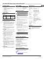
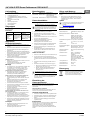
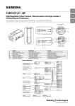
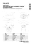
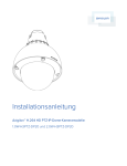
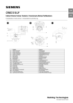
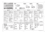
EN
CCID1410-ST
1/4" VGA IP PTZ Dome Colour Camera
1/4" VGA IP PTZ-Dome-Farbkamera
DE
Installation Instruction / Installationsanleitung
1
2
3
4
5
6
7
8
9
10
11
12
13
14
15
16
17
18
English
Mounting plate
Safety wire
Hook
Stopper
Terminal cover
SD Card slot
Default button
Microphone
Reset button
Audio in (φ3.5mm)
Audio out (φ3.5mm)
RJ45 terminal
AC 24 V Power in terminal
Power indicator
Digital I/O terminal
Lens F = 1.8 to 2.9
SD card cover screw
SD card cover
Deutsch
Montageplatte
Sicherungsdraht
Haken
Stopper
Abdeckung der Anschlussklemmen
SD-Kartensteckplatz
Default-Taste
Mikrofon
Reset-Taste
Audio-Eingang (φ 3,5 mm)
Audio-Ausgang (φ 3,5 mm)
RJ45-Anschluss
24 V AC-Netzanschlussklemme
Betriebsanzeige
Digital-I/O-Anschluss
Objektiv F = 1,8 bis 2,9
Schraube der SD-Kartenabdeckung
SD-Kartenabdeckung
Building Technologies
Fire Safety & Security Products
1/4" VGA IP PTZ Dome Colour Camera CCID1410-ST
Package contents
Ordering Data
•
•
•
•
•
•
•
•
•
•
Type
1 x 1/4” VGA IP PTZ-dome
1 x Documentation CD
1 x Utilities CD
1 x Installation instruction (English, German)
1 x Installation instruction (French, Spanish, Italian)
1 x SD card with case (2 GB)
3 x Wall plugs
3 x Mounting screw
1 x Mounting template for installation
1 x Mounting plate
CCID1410-ST S54561-C82-A1
Technical
training for
electrical
installations.
Installs the product,
individual
components of the
product or
replacement parts.
General safety precautions
•
•
•
•
•
•
Read the general safety precautions before installing,
configuring and operating the device.
Keep this document for reference.
Always pass this document on together with the product.
Please also take into account any additional countryspecific, local safety standards or regulations concerning
project planning, operation and disposal of the product.
Follow all warnings and instructions marked on the
device.
Do not attempt to service or modify this device yourself.
Refer this work to qualified service personnel.
Liability claim
• Do not make any changes or modifications to the device
unless they have been approved by the manufacturer.
• Use only spare parts and accessories that have been
approved by the manufacturer.
Installation
•
Transportation
•
•
Keep the packaging material for future transportation.
Do not expose the device to mechanical vibrations or
shocks
1/4”
330K pixels, 640 (H) x 480 (V)
Installing the camera
Resolution
MJPEG: VGA (640 x 480) /
QVGA, (320 x 240) at 30 ips
MPEG4: VGA (640 x 480) /
QVGA, (320 x 240 ) at 30 ips
Mounting on a ceiling
Note: Check if the ceiling structure and material have
a sufficient strength before installing the camera onto a
ceiling. If the amounting strength is inadequate, the
camera will fall, potentially causing an injury or a
camera failure.
1.
Paste the mounting template (1) on a ceiling.
2.
Make a hole in the ceiling where the camera is to be
installed to insert the power cable, LAN cable and other
cables.
3.
Feed all cables through the ceiling hole and the mounting
template hole.
4.
Fix the mounting plate (1) below the hole by using the
included wall plugs and mounting screws.
5.
Tie the safety wire (2) of the mounting plate (1) onto the
safety hook (3) of the camera.
6.
Align the camera grooves with the mounting plate (1).
7.
Push up the camera onto the mounting plate (1) and then
slide the camera back until the security hooks lock.
Connecting the cable
1.
Remove the terminal cover (5).
2.
For configuration and operation of the camera via
Ethernet, connect the network cable to the RJ45 terminal
(12) using a hub or a switch.
3.
4.
Connect the control input to the terminals GND and AL IN
(15).
Min. Illumination
0.7 lux (1/30s F1.8 AGC max.)
Lens
F = 1.8 to 2.9, f: 4.2 – 42 mm, 10x
Pan travel
-175 to +175°
Pan speed
Max. 300 °/s (at preset)
Tilt range
Desktop: -30 to + 90°
Ceiling: -90 to +30°
Tilt speed
Max. 200 °/s (at preset)
Synchronisation
Internal
Network connection
Internet protocols
RJ45, 1 x 10/100 based-T Ethernet
connection for LAN/WAN
TCP/IP, UDP, HTTP, SMTP, DNS,
DHCP, NTP, ARP, ICMP, FTPc, FTPs,
DDNS, RTP (RTCP, RTSP), IGMP v3,
UPnP, NFS, CIFS
Power requirement
24 V AC, PoE
Power consumption
Max. 16 W
Camera weight
0.95 kg
Operating
temperature
0 to +50 °C
Disposal
Electrical and electronic products should be
disposed of separately from the municipal waste
stream via designated collection facilities
appointed by the government or the local
authorities.
Connect the AC Power on the camera.
•
•
Radio interference with other devices in the environment
• When handling modules that are susceptible to
electrostatic discharge, please observe the ESD
guidelines.
Danger of electrical shock due to incorrect connection
• Connect the device only to power sources with the
specified voltage. Voltage supply requirements can be
found on the mains adapter.
• Make sure the device is permanently connected to the
electricity supply; a readily accessible disconnect device
must be provided.
• This device is designed to work with 24 V AC-systems or
PoE. Do not connect the device to any other power
systems
Image sensor
MJPEG / MPEG4
It is recommended that all preparatory work (e.g. fitting of
accessories) be carried out in a workshop prior to final
installation.
Damage due to unsuitable mounting location
• The environmental conditions recommended by the
manufacturer must be observed. See section
Specifications.
• Do not operate the device in dusty places.
• Do not expose the device to mechanical vibrations or
shocks.
• Protect the device against moisture.
• Place the unit on a stable surface that will hold its weight.
• The mounting surface must be solid and noncombustible.
• Do not operate the device close to sources of powerful
electromagnetic radiation.
MJPEG/MPEG-4 IP Colour
PTZ Dome Camera,
24 V AC, 50 Hz or PoE
Image compression
method
Installer
Condition of the
product
Components of the
product are not yet
installed or need to be
replaced or modified.
EN
CCID1410-AB S54561-B202-A1 Adapter for CCDA
Accessories
The instructions in this document are designed only for the
following target readers:
Activity
Specifications
Description
Effective pixels
Target readers
Qualification
Item Number
For 24 V AC: Connect 24 V (~) cables to terminals
~AC 24 V (13).
For PoE: Connect the network cable to the RJ45
terminal (12) using a hub or a switch.
Caution: Incorrect connection may cause malfunction
and/or damage to the camera.
5.
Attach the terminal cover (5). (The terminal cover has the
function to prevent coming off of the AC power cable and
other cables.)
Setting camera parameters
Camera parameters can be modified through the IP
connection. You can follow the user manual of CCID1410-ST
for the IP function and parameter setting.
Presetting of camera position
The presets function of the camera enables you to assign up
to 64 different positions and names for the camera.
Pan/Tilt operation
•
•
•
•
Automatic Patrol can be set.
Automatic scanning can be set.
A PAN/TILT operation range of the camera can be set.
Camera can be set the Left/Right limit position
IP connection
Connect the Ethernet connector with an RJ45 cable, then
follow the user manual of CCID1410-ST for the IP function.
If direct connection to a PC network card is required, a crossover LAN cable should be used.
Care and maintenance
The camera is maintenance-free. Small amounts of dirt or
dust can be cleaned from the camera using a clean soft cloth.
•
Do not touch the lens area. Use a soft cloth moistened
with alcohol to clean the surface if it is touched
accidentally.
Update
For the latest camera firmware update, please refer to
the following download link:
http://www.siemens.com/cctv
2
Siemens Building Technologies
Fire Safety & Security Products
03.2009
1/4" VGA IP PTZ-Dome-Farbkamera CCID1410-ST
Lieferumfang
Bestellangaben
•
•
•
•
•
Typ
1 x 1/4” VGA IP PTZ-Dome
1 x Dokumentations-CD
1 x Dienstprogramme-CD
1 x Installationsanleitung (Englisch, Deutsch)
1 x Installationsanleitung (Französisch, Spanisch,
Italienisch)
1 x SD-Karte mit Hülle (2 GB)
3 x Dübel
3 x Befestigungsschraube
1 x Montageschablone
1 x Montageplatte
•
•
•
•
•
Artikelnummer
CCID1410-ST S54561-C82-A1
Kamerainstallation
Befestigung an der Decke
Hinweis: Vergewissern Sie sich, dass die Decke
hinsichtlich Struktur und Tragfähigkeit für die Montage
der Kamera geeignet ist. Bei ungenügender Stabilität
der Oberfläche kann die Kamera herunterfallen und
dadurch beschädigt werden oder Personenschaden
verursachen.
Die Anweisungen in diesem Dokument gelten nur für
folgende Personen:
Qualifikation
Besitzt
Fachkenntnisse
im Bereich
Elektroinstallationen.
Tätigkeit
Zustand des
Produkts
Einzelkomponenten
Installiert das
Produkt, Einzeldes Produkts sind
komponenten oder noch nicht installiert
Ersatzteile des
oder müssen ersetzt
Produkts.
oder umgebaut
werden.
Allgemeine
Sicherheitshinweise
•
•
•
•
•
•
Lesen Sie die allgemeinen Sicherheitshinweise, bevor
Sie das Gerät installieren, konfigurieren und in Betrieb
nehmen.
Bewahren Sie dieses Dokument zum Nachschlagen auf.
Geben Sie dieses Dokument bei der Weitergabe des
Produktes mit.
Beachten Sie bitte alle zusätzlichen länderspezifischen,
lokalen Sicherheitsnormen oder -vorschriften hinsichtlich
Projektplanung, Betrieb und Entsorgung des Produkts.
Befolgen Sie alle auf dem Gerät angebrachten
Warnungen und Anweisungen.
Lassen Sie Wartungsarbeiten und Änderungen an
diesem Gerät nur von Fachpersonal durchführen.
Haftungsanspruch
• Nehmen Sie nur Veränderungen am Gerät vor, die vom
Hersteller genehmigt sind.
• Verwenden Sie ausschließlich vom Hersteller
genehmigte Ersatz- und Zubehörteile.
Montage
•
Schäden aufgrund eines ungeeigneten Montageortes
• Beachten Sie die vom Hersteller empfohlenen
Umgebungsbedingungen. Siehe Abschnitt Technische
Daten.
• Betreiben Sie das Gerät nicht an staubigen Orten.
• Setzen Sie das Gerät keinen mechanischen
Erschütterungen oder Stößen aus.
• Schützen Sie das Gerät vor Feuchtigkeit und Nässe.
• Achten Sie bei der Aufstellung des Gerätes auf stabilen
Untergrund und sicheren Stand.
• Montieren Sie das Gerät nur auf festen und nicht
brennbaren Oberflächen.
• Betreiben Sie das Gerät nicht in der Nähe starker
elektromagnetischer Strahlung.
Stromschlaggefahr durch falschen Anschluss an die
Spannungsversorgung
• Schließen Sie das Gerät nur an Stromquellen mit der
vorgeschriebenen Spannung an. Angaben zur
Versorgungsspannung finden Sie auf dem Netzteil.
• Betreiben Sie das Gerät nur mit Festanschluss und gut
zugänglicher Trennvorrichtung am Versorgungskreis.
• Dieses Gerät ist ausgelegt für den Betrieb mit 24 V ACSystemen oder PoE. Schließen Sie das Gerät nicht an
andere Stromversorgungsnetze an
Transport
•
•
Bewahren Sie das Verpackungsmaterial für einen
zukünftigen Transport auf.
Setzen Sie das Gerät keinen mechanischen
Erschütterungen oder Stößen aus.
Die Kamera ist wartungsfrei. Bei leichter Verschmutzung
kann das Kameragehäuse mit einem weichen Tuch gereinigt
werden.
•
Berühren Sie nicht den Objektivbereich. Sollte es
versehentlich berührt worden sein, reinigen Sie die
Oberfläche mit einem weichen, leicht mit Alkohol
getränkten Tuch.
Update
Informieren Sie sich unter folgendem Download-Link
über die neusten Aktualisierungen der KameraFirmware:
http://www.siemens.com/cctv
Technische Daten
Bildsensor
1/4”
Effektive Bildpunkte
330K Bildpunkte, 640 (H) x 480
(V)
1.
Kleben Sie die Schablone (1) an die Decke.
2.
Schneiden Sie dort, wo Sie die Kamera montieren
wollen, ein Loch in die Decke für das Netz-, LAN- und
sonstige Kabel.
3.
Führen Sie alle Kabel durch das Loch in der Decke und
das Loch in der Montageschablone.
4.
Bringen Sie die Montageplatte (1) mit den im
Lieferumfang enthaltenen Dübel und
Befestigungsschrauben auf diesem Loch an.
Mindestbeleuchtungsstärke 0,7 lux (1/30s F1,8 AVR max.)
5.
Ziehen Sie den Sicherungsdraht (2) der Montageplatte
(1) über den Sicherungshaken (3) in der Kamera.
Schwenkbereich
-175 bis +175°
Schwenkgeschwindigkeit
Max. 300 °/s (bei Positionierung)
6.
Richten Sie die Einkerbungen an der Kamera mit der
Montageplatte aus.
Neigebereich
Desktop-Montage: -30 bis + 90°
Deckenmontage: -90 bis +30°
7.
Drücken Sie die Kamera auf die Montageplatte und
schieben Sie dann die Kamera nach hinten, bis die
Sicherungshaken einrasten.
Neigegeschwindigkeit
Max. 200 °/s (bei Positionierung)
Synchronisation
Intern
Netzwerkanschluss
Internetprotokolle
RJ45, 1 x 10/100baseTEthernet-Anschluss für
LAN/WAN
TCP/IP, UDP, HTTP, SMTP,
DNS, DHCP, NTP, ARP, ICMP,
FTPc, FTPs, DDNS, RTP
(RTCP, RTSP), IGMP v3, UPnP,
NFS, CIFS
24 V AC, PoE
Kabel anschließen
Bildkompressionsverfahren MJPEG / MPEG4
Auflösung
MJPEG: VGA (640 x 480) /
QVGA, (320 x 240) bei 30 ips
MPEG4: VGA (640 x 480) /
QVGA, (320 x 240 ) bei 30 ips
Objektiv
F = 1,8 bis 2,9, f: 4,2 – 42 mm,
10x
1.
Entfernen Sie die Abdeckung der Anschlussklemmen (5).
2.
Um die Kamera über Ethernet parametrieren und
bedienen zu können, schließen Sie das Netzwerkkabel
mit einem Hub oder Switch an den RJ45-Anschluss (12)
an.
3.
Schließen Sie den Steuereingang an GND und AL IN
(15) an.
Leistungsaufnahme
Leistungsaufnahme
Max. 16 W
Schließen Sie die Kamera an die AC-Versorgung an.
Gewicht der Kamera
0,95 kg
•
Betriebstemperatur
0 bis +50 °C
4.
Wir empfehlen Ihnen, alle vorbereitenden Arbeiten (wie z.
B. Installation von Zubehörteilen) an einem dafür
vorgesehenen Ort (z. B. in einer Werkstatt) vor der
endgültigen Installation des Produkts auszuführen.
Funkstörungen im Umfeld anderer Geräte
• Beachten Sie beim Berühren von elektrostatisch
gefährdeteten Baugruppen und Bauteilen die
Handhabungsvorschriften (EGB-Richtlinie).
MJPEG/MPEG-4 IP-PTZDome-Farbkamera,
24 V AC, 50 Hz oder PoE
CCID1410-AB S54561-B202-A1 Adapter für CCDA-Zubehör
Zielgruppen
Installateur
Pflege und Wartung
Beschreibung
•
Bei 24 V AC: Schließen Sie die 24 V AC-Leitungen
an die Klemmen ~AC 24 V (13) an.
Bei PoE: Schließen Sie das Netzwerkkabel mit
einem Hub oder einem Switch an den RJ45Anschluss (12) an.
Hinweis: Bei falschem Anschluss kann zu Ausfall
und/oder Beschädigung der Kamera kommen.
5.
Bringen Sie die Abdeckung der Anschlussklemmen (5)
wieder an. (Die Abdeckung der Anschlussklemmen soll
verhindern, dass sich die AC-Versorgungskabel und
andere Kabel lösen.)
Entsorgung
Elektrische und elektronische Geräte dürfen
nicht im Hausmüll entsorgt werden, sondern
sind an den von den Kommunen dafür
eingerichteten Sammelstellen abzugeben.
Einstellung der
Kameraparameter
Die Kameraparameter können über den IP-Anschluss
geändert werden. Informationen zur IP-Funktion und
Parametrierung finden Sie im Benutzerhandbuch für
CCID1410-ST.
Kamerapositionen einstellen
Mit der Preset-Funktion können Sie der Kamera bis zu 64
Positionen mit entsprechenden Namen zuweisen.
Schwenk-/Neige-Betrieb
•
•
•
•
Automatische "Patrol"-Funktion kann eingestellt werden.
Automatische "Scan"-Funktion kann eingestellt werden.
Schwenk-/Neigebereich der Kamera kann eingestellt
werden.
Endposition der Kamerabewegung links/rechts kann
eingestellt werden.
IP-Anschluss
Schließen Sie an den Ethernet-Anschluss ein RJ45-Kabel an
und gehen Sie dann wie im Benutzerhandbuch der
CCID1410-ST für die IP-Funktion beschrieben vor.
Falls ein direkter Anschluss an eine PC-Netzwerkkarte
erforderlich ist, sollte ein gekreuztes LAN-Kabel verwendet
werden.
3
Siemens Building Technologies
Fire Safety & Security Products
03.2009
DE
Issued by
Siemens Building Technologies
Fire & Security Products GmbH & Co. oHG
D-76181 Karlsruhe
www.buildingtechnologies.siemens.com
Document no.
A6V10238586
Edition
31.03.2009
© 2009 Copyright by
Siemens Building Technologies
Data and design subject to change without notice.
Supply subject to availability.