1
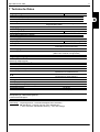
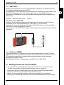
Aqua Sensor
AS 1000
Benutzerhandbuch
(Originalanleitung)
User manual
Mat –Nr. 669705 / Stand: 22.07.2013 D / E
(Translation of original manual)
2
Aqua Sensor AS 1000
Inhalt
D
1 Allgemeines ................................................................................................................. 4
2 Sicherheitshinweise .................................................................................................... 4
3 Montage ........................................................................................................................ 4
4 Funktionsweise............................................................................................................ 5
4.1
Idealer Sättigungsgrad in Hydraulik und Schmiersystemen ................................. 5
4.1.1
Arbeitsbereich AS 1008 (für mineralölbasierende Flüssigkeiten) ................. 6
4.1.2
Arbeitsbereich AS 1108 (für synthetische und natürliche Ester)................... 6
5 Funktionen ................................................................................................................... 6
5.1
Ausführung mit Analogausgängen ................................................................................ 6
5.2
Ausführung mit 2 Schaltausgängen (siehe auch Grafik S. 9) .............................. 7
5.2.1
Ausgangsverhalten ............................................................................................ 7
5.2.2
Schaltausgänge.................................................................................................. 7
5.2.3
Einstellung der beiden Schaltausgänge .......................................................... 8
5.2.4
Grafische Darstellung des Ausgangsverhaltens............................................. 9
6 Elektrischer Anschluss ............................................................................................. 10
7 Technische Daten ...................................................................................................... 11
8 Bestellangaben .......................................................................................................... 12
9 Geräteabmessungen ................................................................................................. 12
10 Zubehör ..................................................................................................................... 13
10.1
Elektrisch ................................................................................................................................... 13
10.2
Mechanisch ............................................................................................................................. 13
11 Anzeigen.................................................................................................................... 14
11.1
HDA 5500 ................................................................................................................................... 14
11.2
HMG 510 ..................................................................................................................................... 14
11.3
HMG 30X0 .................................................................................................................................. 15
11.4
Software CMWIN ..................................................................................................................... 15
12 Wichtige Hinweise auf einen Blick .......................................................................... 15
Stand: 22.07.2013
HYDAC ELECTRONIC GMBH
Mat. Nr.: 669705
Aqua Sensor AS 1000
3
Vorwort
Für Sie, den Benutzer unseres Produktes, haben wir in dieser
Dokumentation die wichtigsten Hinweise zum Bedienen und
Warten zusammengestellt.
Sie dient Ihnen dazu, das Produkt kennen zu lernen und seine
bestimmungsgemäßen Einsatzmöglichkeiten optimal zu nutzen.
Diese Dokumentation muss ständig am Einsatzort verfügbar
sein.
Bitte beachten Sie, dass die in dieser Dokumentation
gemachten Angaben der Gerätetechnik zu dem Zeitpunkt der
Literaturerstellung entsprechen. Abweichungen bei technischen
Angaben, Abbildungen und Maßen sind deshalb möglich.
Entdecken Sie beim Lesen dieser Dokumentation Fehler oder
haben weitere Anregungen und Hinweise, so wenden Sie sich
bitte an:
HYDAC ELECTRONIC GMBH
Technische Dokumentation
Hauptstraße 27
66128 Saarbrücken
-DeutschlandTel:
+49(0)6897 / 509-01
Fax: +49(0)6897 / 509-1726
Email: [email protected]
Die Redaktion freut sich über Ihre Mitarbeit.
„Aus der Praxis für die Praxis“
Stand: 22.07.2013
HYDAC ELECTRONIC GMBH
Mat. Nr.: 669705
D
4
Aqua Sensor AS 1000
1 Allgemeines
D
Falls Sie Fragen bezüglich der technischen Daten oder Eignung des Gerätes für Ihre
Anwendungen haben, wenden Sie sich bitte an unseren Technischen Vertrieb. Der
AS 1000 wird einzeln auf rechnergesteuerten Prüfplätzen abgeglichen und einem Endtest
unterzogen. Er arbeitet beim Einsatz innerhalb der vorgegebenen Spezifikationen (siehe
Technische Daten) einwandfrei.
Falls trotzdem Fehler auftreten sollten, wenden Sie sich bitte an den HYDAC-Service.
Fremdeingriffe in das Gerät führen zum Erlöschen jeglicher Gewährleistungsansprüche.
2 Sicherheitshinweise
Der Aqua Sensor AS 1000 ist bei bestimmungsgemäßer Verwendung grundsätzlich
betriebssicher. Um jedoch Gefahren für Benutzer und Sachschäden infolge falscher
Handhabung des Gerätes zu vermeiden, beachten Sie bitte die folgenden
Sicherheitshinweise:
•
•
•
•
•
•
•
•
Überprüfen Sie vor der Inbetriebnahme den ordnungsgemäßen Zustand des Gerätes
Lesen Sie vor der Inbetriebnahme die Bedienungsanleitung und stellen Sie sicher, dass
das Gerät für Ihre Anwendung geeignet ist.
Während des Transportes ist die Vibrations- und Schockfestigkeit deutlich eingeschränkt.
Der AS 1000 darf nur in einwandfreiem technischem Zustand benutzt werden.
Die Montagehinweise sind einzuhalten.
Die Angaben auf dem Typenschild sind zu beachten.
Störungssuche und Reparatur sind nur von unserem Kundendienst HYDAC-Service
durchzuführen.
Alle einschlägigen und allgemein anerkannten sicherheitstechnischen Bestimmungen sind
einzuhalten.
Falsche Handhabung bzw. die Nichteinhaltung von Gebrauchshinweisen oder
technischen Angaben kann zu Sach- und / oder Personenschäden führen.
3 Montage
Der Sensor kann über den Gewindeanschluss direkt an der Hydraulikanlage montiert
werden. Die empfohlene Einbaulage für hydraulische Anwendungen ist senkrecht mit dem
mechanischen Gewindeanschluss nach oben. Beim Einbau ist darauf zu achten, dass der
Sensor vollständig im Medium eintaucht und dieses frei um den Sensor zirkulieren kann,
daher sollten beim Tankeinbau nur Stellen vorgesehen werden, an denen bekannte
Turbulenzen herrschen.
Der elektrische Anschluss sollte von einem Fachmann nach den jeweiligen Landesvorschriften durchgeführt werden (VDE 0100 in Deutschland).
Die Sensoren der Serie AS 1000 tragen das CE - Zeichen. Eine Konformitätserklärung ist
auf Anfrage erhältlich. Die EMV-Normen: EN 61000-6-1, EN 61000-6-2, EN 61000-6-3 und
EN 61000-6-4 werden erfüllt. Die Forderungen der Normen werden nur bei
ordnungsgemäßer und fachmännischer Erdung des Sensorgehäuses erreicht. Beim
Einschrauben in einen Hydraulikblock ist es ausreichend, wenn der Block über das
Hydrauliksystem geerdet ist.
Zusätzliche Montagehinweise, die erfahrungsgemäß den Einfluss elektromagnetischer
Störungen reduzieren:
•
•
•
•
Möglichst kurze Leitungsverbindungen herstellen.
Leitungen mit Schirm verwenden (z.B. LIYCY 5 x 0,5 mm²).
Der Kabelschirm ist in Abhängigkeit der Umgebungsbedingungen fachmännisch und zum
Zweck der Störunterdrückung einzusetzen.
Direkte Nähe zu Verbindungsleitungen von Leistungsverbrauchern und störenden Elektrooder Elektronikgeräten ist möglichst zu vermeiden.
Stand: 22.07.2013
HYDAC ELECTRONIC GMBH
Mat. Nr.: 669705
Aqua Sensor AS 1000
5
4 Funktionsweise
Die Aqua-Sensoren der Serie AS 1000 sind Wasser- und Temperatursensoren zur
kontinuierlichen und präzisen Online-Überwachung von Hydraulik- und Schmierfluiden.
Sie erfassen den Wassergehalt relativ zur Sättigungskonzentration (Sättigungspunkt).
Hierbei bedeuten 0% wasserfreies Öl und 100% vollkommen mit Wasser gesättigtes Öl.
Der zur Messung des Sättigungsgrades verwendete kapazitive Sensor absorbiert
Wassermoleküle aus dem Fluid, was zu einer Änderung der Kapazität des Sensorelements
führt. Der hieraus erhaltene Messwert stellt den Sättigungsgrad des Fluids in Prozent dar.
Ein auf dem Sensor integriertes Thermoelement misst die Temperatur im Bereich von
-25 ... +100°C.
In der Variante mit 2 Schaltausgängen schalten die Schaltausgänge entsprechend dem
Sättigungsgrad und den eingestellten Schaltparametern. Es besteht die Möglichkeit den AS
1000- Sensor individuell mit dem HYDAC Servicegerät HMG 30X0 oder der Software
CMWIN an die jeweilige Applikation anzupassen.
Freies Wasser
4.1 Idealer Sättigungsgrad in Hydraulik und Schmiersystemen
Da die Auswirkungen von freiem (bzw. emulgiertem) Wasser wesentlich schädlicher sind
als von gelöstem Wasser, sollte der Wassergehalt immer deutlich unterhalb des
Sättigungspunktes liegen. Selbst gelöstes Wasser kann jedoch Schäden verursachen. Es
sollten deshalb alle sinnvollen Maßnahmen unternommen werden, um den Sättigungsgrad
so niedrig wie möglich zu halten. Hydraulik- und Schmierfluide können nicht „zu trocken“
sein!
Als Richtwert empfehlen wir in allen Anlagen einen Sättigungsgrad von unter 45%.
Sättigungsgrad
Sättigungspunkt
75 %
Gelöstes Wasser
100%
50 %
25 %
0%
Stand: 22.07.2013
HYDAC ELECTRONIC GMBH
Mat. Nr.: 669705
D
6
Aqua Sensor AS 1000
110
100
90
80
70
60
50
40
30
20
10
0
-40 -30 -20 -10 0 10 20 30 40 50 60 70 80 90 100 110 120 130 140 150 160 170 180 190
Temperatur [°C]
Die Abbildung zeigt den zulässigen Arbeitsbereich des Aqua-Sensors AS 1008. Wird der
Sensor außerhalb des grau gefärbten Bereiches dauerhaft betrieben, können bleibende
Schäden am Sensorelement entstehen.
4.1.2 Arbeitsbereich AS 1108 (für synthetische und natürliche Ester)
Sättigungsgrad [%]
D
Sättigungsgrad [%]
4.1.1 Arbeitsbereich AS 1008 (für mineralölbasierende Flüssigkeiten)
110
100
90
80
70
60
50
40
30
20
10
0
-30 -20 -10
0
10
20
30
40
50
60
70
80
90 100 110 120 130 140
Temperatur [°C]
Die Abbildung zeigt den zulässigen Arbeitsbereich des Aqua-Sensors AS 1108. Wird der
Sensor außerhalb des grau gefärbten Bereiches dauerhaft betrieben, können bleibende
Schäden am Sensorelement entstehen.
5 Funktionen
5.1 Ausführung mit Analogausgängen
Mit dem Analogausgang 1 bzw. Analogausgang 2 können die folgenden Messgrößen in
ihren Grenzen angezeigt werden:
Sättigungsgrad:
0 % ... 100 %
Temperatur:
-25 °C ... +100 °C
Die Ausgänge sind immer als Stromausgänge (4 ... 20 mA Quelle) konfiguriert.
Achtung:
Bei einer Anzeige von 100 % bedeutet diese entweder freies Wasser oder fehlerhafter
Sensor.
Stand: 22.07.2013
HYDAC ELECTRONIC GMBH
Mat. Nr.: 669705
Aqua Sensor AS 1000
7
5.2 Ausführung mit 2 Schaltausgängen (siehe auch Grafik S. 9)
• Schalten der Schaltausgänge entsprechend dem Sättigungsgrad und den eingestellten
Schaltparametern
• Anpassen des AS 1000 an die jeweilige Applikation durch individuelle BenutzerProgrammierung mit dem HYDAC Servicegerät HMG 30X0 oder der Software CMWIN.
5.2.1
Ausgangsverhalten
Der AS 1000-2 verfügt über 1 bzw. 2 Schaltausgänge mit folgenden Funktionen:
- SP1: Schaltausgang 1 (Pin 4) dient als Alarm
- SP2: Schaltausgang 2 (Pin 2) dient als Warnung
Voreistellungen:
Die Schaltausgänge sind auf Sättigung voreingestellt.
SP 1 (Pin 2): 80 %, Hysterese 3%
SP 2 (Pin 4): 60 %, Hysterese 3%
Aktivierungstemperatur: 30°C
Übertemperatur: 80°C
In den Grundeinstellungen kann folgender Schaltverhalt eingestellt werden:
5.2.2
Schaltausgänge
Verhalten innerhalb des vorgegebenen Temperaturbereichs
Die Schaltausgänge sind nur im Arbeitsbereich aktiv, wenn:
aktuelle Temperatur ≥ Aktivierungstemperatur und
aktuelle Temperatur < Übertemperatur
Die Schaltpunkte beziehen sich auf die Sättigung. Zu jedem Schaltausgang kann ein
Schaltpunkt und ein Rückschaltpunkt (RP) eingestellt werden. Der jeweilige Ausgang
schaltet, wenn der eingestellte Schaltpunkt erreicht wurde und schaltet zurück, wenn der
Rückschaltpunkt unterschritten wurde. Der Rückschaltpunkt wird durch die eingestellte
Hysterese bestimmt (Rückschaltpunkt = Schaltpunkt – Hysterese).
Damit SP2 immer als Warnung und vor SP1 schaltet, muß folgendes gelten:
• SP2 < SP1
• SP2-HYS2 < SP1-HYS1 ( RP2 < RP1)
Verhalten außerhalb des vorgegebenen Temperaturbereichs
Die Schaltausgänge verhalten sich wie in unten stehender Tabelle, wenn:
aktuelle Temperatur < Aktivierungstemperatur oder
aktuelle Temperatur > Übertemperatur
Öffner
aktuelle Temperatur <
Aktivierungstemperatur
aktuelle Temperatur >
Übertemperatur
Stand: 22.07.2013
Schließer
SP1
SP2
(Alarm)
(Warnung)
SP1
(Alarm)
SP2
(Warnung)
geschaltet
geschaltet
aus
aus
aus
geschaltet
geschaltet
aus
HYDAC ELECTRONIC GMBH
Mat. Nr.: 669705
D
8
D
Aqua Sensor AS 1000
5.2.3 Einstellung der beiden Schaltausgänge
Mit Hilfe des HMG 3010 oder mit der Software CMWIN haben Sie die Möglichkeit die
Schaltpunkte des Sensors zu konfigurieren.
Im Hauptmenü “SMART-Sensor“ wählen Sie den Menüpunkt „Sensordialog“ aus. Hier
können Sie die Konfigurationen des SMART-Sensors vornehmen.
• Schaltausgang 1: Quelle, Ausgang, Einschaltpunkt, Ausschaltpunkt,
Einschaltverzögerung, Ausschaltverzögerung
• Schaltausgang 2: Quelle, Ausgang, Einschaltpunkt, Ausschaltpunkt,
Einschaltverzögerung, Ausschaltverzögerung
Einstellbereiche der Parameter
Messbereich
Untere Grenze Obere Grenze Mindestabstand Schrittweite*
Sättigungsgrad
von RP
von SP
zw. RP und SP
in %
in %
in %
in %
0 .. 100
1,0
100,0
1,0
0,2
* Die in der Tabelle angegebenen Bereiche sind im Raster der Schrittweite einstellbar.
• Arbeitstemperatur: Aktivierungstemperatur AT(gilt für beide Schaltausgänge) ,
Übertemperatur UET
Einstellbereiche der Parameter
AT
UET
Schrittweite
-25 … 100 °C
0,1 °C
Stand: 22.07.2013
-25 … 100 °C
HYDAC ELECTRONIC GMBH
Mat. Nr.: 669705
Aqua Sensor AS 1000
9
5.2.4 Grafische Darstellung des Ausgangsverhaltens
D
Stand: 22.07.2013
HYDAC ELECTRONIC GMBH
Mat. Nr.: 669705
10
Aqua Sensor AS 1000
6 Elektrischer Anschluss
D
1
2
AS 1000-C
3
4
5
1
2
AS 1000-2
RL
GND
RL
Signal Temperatur
HSI
RL
3
4
5
+Ub
Signal Sättigungsgrad
+UB
SP2, Warnung
GND
RL
SP 1, Alarm
HSI
* HSI = HYDAC Sensor Interface (HYDAC-interne Kommunikations-Schnittstelle)
RLmax = (Ub – 10 V) / 20 mA [kΩ]
Stand: 22.07.2013
HYDAC ELECTRONIC GMBH
Mat. Nr.: 669705
Aqua Sensor AS 1000
11
7 Technische Daten
AS 1X00-C
AS 1X00-2
0 .. 100 %
-25 .. +100 °C
max. 50 bar
max. 630 bar
Edelstahl, FPM- / oder EPDM-Dichtung, Keramik mit
aufgedampftem Metall
Eingangskenngrößen
Messbereich (Sättigungsgrad)
Messbereich (Temperatur)
Betriebsdruck
Druckfestigkeit
Medienberührende Teile
Ausgangsgröße
Pin 2: Sättigungsgrad
Ausgangssignal
Kalibriergenauigkeit
Genauigkeit bei Messung in Medien
Druckabhängigkeit
Pin 4:Temperatur
Ausgangssignal
Genauigkeit
Pin 5:
Schaltausgänge
Ausführung
4 .. 20 mA
Schaltausgang (konfigurierbar)
≤ ± 2 % FS max.
≤ ± 3 % FS typ.
+ 0,025 % FS / bar
4 .. 20 mA
Schaltausgang (konfigurierbar)
≤ ± 2% FS max.
HSI (HYDAC Sensor Interface)
Automatische Sensorerkennung
PNP- Transistor-Schaltausgänge
(Öffner oder Schließer, konfigurierbar)
max. 1A je Schaltausgang
Schaltstrom
Umgebungsbedingungen
Nenntemperaturbereich
(Messung Sättigungsgrad)
1)
Umgebungstemperaturbereich
1)
Mediumstemperaturbereich
Viskositätsbereich
Strömungsgeschwindigkeit
Medienverträglichkeit
0 .. + 90 °C
-40 .. +100 °C / -25 .. +100 °C
-40 .. +125 °C / -25 .. +100 °C
1 .. 5000 cSt
< 5 m/s
mineralölbasierende Flüssigkeiten,
synthetische und natürliche Ester
EN 61000-6-1, EN 61000-6-2
EN 61000-6-3, EN 61000-6-4
IP 67
- Zeichen
Schutzart nach
Sonstige Größen
Versorgungsspannung
Restwelligkeit Versorgungsspannung
Mechanischer Anschluss
Anzugsdrehmoment
Elektrischer Anschluss
12 .. 32 V DC
≤5%
G3/8A DIN 3852
ca. 25 Nm
M12x1, 5-polig
Verpolungsschutz der Versorgungsspannung,
Überspannungs-, Übersteuerungsschutz,
Lastkurzschlussfestigkeit
Gewicht
Anmerkung:
vorhanden
ca. 145 g
Verpolungsschutz , Kurzschlussfestigkeit sind vorhanden.
FS (Full Scale) = bezogen auf den vollen Messbereich
1)
- 25°C mit FPM- oder EPDM- Dichtung, - 40°C auf Anfrage
Stand: 22.07.2013
HYDAC ELECTRONIC GMBH
Mat. Nr.: 669705
D
12
Aqua Sensor AS 1000
8 Bestellangaben
AS
D
1 X 0 8 - X - 000
Medium
0 = Mineralöle
1 = Phosphat-Ester, z.B. Skydrol
Anschlussart mechanisch
0 = G 3/8A DIN 3852
Anschlussart elektrisch
8 = Gerätestecker M12x1, 5-pol. (ohne Kupplungsdose)
Signaltechnik
C = Ausgang 1 (Pin2) Sättigungsgrad ( 4 .. 20 mA Quelle)
Ausgang 2 (Pin4) Temperatur (4 .. 20 mA Quelle)
2 = 2 Schaltausgänge konfigurierbar
Modifikationsnummer
000 = Standard
Anmerkungen:
Sonderausführungen auf Anfrage.
Bei Geräten mit anderer Modifikationsnummer ist das Typenschild bzw. die mitgelieferte technische
Änderungsbeschreibung zu beachten.
9 Geräteabmessungen
Stand: 22.07.2013
HYDAC ELECTRONIC GMBH
Mat. Nr.: 669705
Aqua Sensor AS 1000
13
10 Zubehör
10.1 Elektrisch
D
ZBE 08 (5-pol.)
Kupplungsdose M12x1, abgewinkelt
Bestell-Nr.: 6006786
ZBE 08-02 (5-pol.) mit 2m Leitung
Bestell-Nr.: 6006792
ZBE 08-05 (5-pol.) mit 5m Leitung
Bestell-Nr.: 6006791
ZBE 08S-02 (5-pol.)
mit 2m Leitung geschirmt
Bestell-Nr.: 6019455
ZBE 08S-05 (5-pol.)
mit 5m Leitung geschirmt
Bestell-Nr.: 6019456
ZBE 08S-10 (5-pol.)
mit 10m Leitung geschirmt
Bestell-Nr.: 6023102
Farbkennung:
Pin 1: braun
Pin 2: weiß
Pin 3: blau
Pin 4: schwarz
Pin 5: grau
ZBE 36
Adapter AS / HLB - HMG 3000
Bestell-Nr.: 909737
ZBE 30-02
Sensorkabel M12x1, 2m
Bestell-Nr.: 6040851
ZBE 30-05
Sensorkabel M12x1, 5m
Bestell-Nr.: 6040852
10.2 Mechanisch
ZBM 22
Adapter zum Einbringen in eine
Leitung G1/2“
Bestell-Nr.: 3248511
Stand: 22.07.2013
HYDAC ELECTRONIC GMBH
Mat. Nr.: 669705
14
Aqua Sensor AS 1000
11 Anzeigen
D
11.1 HDA 5500
Das HDA 5500 in der Ausführung HDA 5500-1-1-AC-000 bzw.
HDA 5500-1-1-DC-000 ist ein Anzeigegerät mit 4
programmierbaren Schaltausgängen, speziell auf den AS 1000
zugeschnitten.
In Verbindung mit dem HDA 5500 ist es möglich, die aktuellen
Messwerte zur Anzeige zu bringen.
Bestell-Nr.: 908869 HDA 5500-1-1-AC-000
Bestell-Nr.: 908870 HDA 5500-1-1-DC-000
Anschluss eines AS 1000 mit Analogausgang an ein HDA 5500
X1:
Pin 1: + Versorgung HDA 5500
X1:
Pin 2: - Versorgung HDA 5500
X2: Pin 5:
X2: Pin 6:
X2: Pin 8:
X2: Pin 7:
GND AS 1000
+12V Versorgung AS 1000
Temperatur
Sättigungsgrad
(blau)
(braun)
(schwarz)
(weiß)
11.2 HMG 510
Mobiles 2-Kanal Handmessgerät, speziell zur Messwertanzeige von HSI- und SMARTSensoren.
In Verbindung mit dem HMG 510 ist es möglich, die aktuellen Messwerte auf dem Display
des HMG 510 zur Anzeige zu bringen.
Bestell-Nr.: 909889 HMG 510-000
Anschluss an ein HMG 510
Entfernen Sie die Versorgungsleitung vom elektrischen Anschluss des AS 1000 und
schrauben Sie den Anschlussadapter AS / HLB „ZBE 36“ auf den Sensor. Verbinden Sie
einen der Eingänge A oder B des HMG 510 mittels eines Sensorkabels
„ZBE 30-0x“ mit dem Ausgang des „ZBE 36“
Stand: 22.07.2013
HYDAC ELECTRONIC GMBH
Mat. Nr.: 669705
Aqua Sensor AS 1000
15
11.3 HMG 30X0
Mobiles Handmessgerät mit einem vollgrafikfähigen Farbdisplay zur Messwertanzeige
bzw. Messwertaufzeichnung des AS 1000.
In Verbindung mit dem HMG 30X0 können die aktuellen Messwerte auf dem Display des
HMG 30X0 angezeigt werden. Die Aufnahmen können auf dem HMG 30X0 auch
gespeichert und bearbeitet werden (genaue Beschreibung siehe Bedienungsanleitung
HMG 30X0).
Bestell-Nr.: HMG 3010-000-D DE
920932
Anschluss an ein HMG 30X0
Entfernen Sie die Versorgungsleitung vom elektrischen Anschluss des AS 1000 und
schrauben Sie das Anschlussadapter AS / HLB „ZBE 36“ auf den Sensor.
Verbinden Sie einen der Eingänge A bis D des HMG 30X0 mittels eines Sensorkabels
„ZBE 30-0x“ mit dem Ausgang des „ZBE 36“.
Bei Anschluss an ein HMG 30X0 erfolgt die Spannungsversorgung des Sensors über das
Messgerät.
11.4 Software CMWIN
Speziell entwickelte PC-Software, die mittels Kommunikationsbrücke (HMG 510 oder
HMG 30X0) mit dem AS 1000 kommuniziert. Mit der Software können Messkurven zum
PC übertragen, gespeichert, angezeigt und bearbeitet werden oder die aktuellen
Messwerte dargestellt werden.
Die CMWIN ist Teil des Lieferumfanges des HMG 510 und HMG 30X0.
12 Wichtige Hinweise auf einen Blick
• Wir empfehlen für hydraulische Anwendungen, den Sensor in senkrechter Lage
mit dem mechanischen Gewindeanschluss nach oben zu montieren.
• Bitte achten Sie beim Einbau darauf, dass der Sensor vollständig in das Medium
eintaucht und dieses frei durch den Sensor zirkulieren kann.
• Stellen Sie einen stetigen Durchfluss sicher und vermeiden Sie möglichst die
Bildung von Luftblasen. Bei stehendem Öl sind erhöhte Messabweichungen möglich.
Stand: 22.07.2013
HYDAC ELECTRONIC GMBH
Mat. Nr.: 669705
D
16
D
Aqua Sensor AS 1000
HYDAC ELECTRONIC GMBH
Hauptstr. 27
D-66128 Saarbrücken
Germany
Web:
E-Mail:
Tel.:
Fax.:
www.hydac.com
[email protected]
+49 (0)6897 509-01
+49 (0)6897 509-1726
HYDAC Service
Für Fragen zu Reparaturen steht Ihnen der HYDAC Service zur Verfügung.
HYDAC SERVICE GMBH
Hauptstr. 27
D-66128 Saarbrücken
Germany
Tel.:
Fax:
+49 (0)6897 509-1936
+49 (0)6897 509-1933
Anmerkung
Die Angaben in dieser Bedienungsanleitung beziehen sich auf die beschriebenen
Betriebsbedingungen und Einsatzfälle. Bei abweichenden Einsatzfällen und/oder
Betriebsbedingungen wenden Sie sich bitte an die entsprechende Fachabteilung.
Bei technischen Fragen, Hinweisen oder Störungen nehmen Sie bitte Kontakt mit Ihrer
HYDAC-Vertretung auf.
Technische Änderungen sind vorbehalten.
Stand: 22.07.2013
HYDAC ELECTRONIC GMBH
Mat. Nr.: 669705
Aqua Sensor
AS 1000
User manual
Part no.: 669705 / status: 2013/07/22
(Translation of original instructions)
2
Aqua Sensor AS 1000
Contents
E
1
General.................................................................................................................................................... 4
2
Safety information .............................................................................................................................. 4
3
Installation ............................................................................................................................................. 4
4
Function ................................................................................................................................................. 5
4.1 Ideal saturation level in hydraulic and lubrication systems .................................. 5
5
4.1.1
Working range for AS 1008 (for mineral oil based fluids)............................... 6
4.1.2
Working range for AS 1108 (for synthetic and natural esters) ....................... 6
Functions ............................................................................................................................................... 6
5.1 Model with analogue outputs ................................................................................... 6
5.2 Version with 2 switch outputs .................................................................................. 7
5.2.1
Output settings................................................................................................... 7
5.2.2
Switching outputs .............................................................................................. 7
5.2.3
Setting of both switching outputs .................................................................... 8
5.2.4
Graphical representation of the output behaviour .......................................... 9
6
Electrical connection ...................................................................................................................... 10
7
Technical Details .............................................................................................................................. 11
8
Order Details....................................................................................................................................... 12
9
Dimensions ......................................................................................................................................... 12
10 Accessories ........................................................................................................................................ 13
10.1 Electrical .................................................................................................................. 13
10.2 Mechanical ............................................................................................................... 13
11 Displays ................................................................................................................................................ 14
11.1 HDA 5500 .................................................................................................................. 14
11.2 HMG 510 ................................................................................................................... 14
11.3 HMG 30X0................................................................................................................. 15
11.4 Software CMWIN ...................................................................................................... 15
12 Important tips at a glance ............................................................................................................. 15
Edition: 2013-07-22
HYDAC ELECTRONIC GMBH
Part No.: 669705
Aqua Sensor AS 1000
3
Preface
This manual provides you, as user of our product, with key
information on the operation and maintenance of the
equipment.
It will acquaint you with the product and assist you in obtaining
maximum benefit in the applications for which it is designed.
Always keep the manual with the instrument for immediate
reference.
Please note: the specifications given in this documentation
regarding the instrument technology were correct at the time of
publishing. Modifications to technical specifications, illustrations
and dimensions are therefore possible.
If you discover errors while reading the documentation or have
additional suggestions or tips, please contact us at:
HYDAC ELECTRONIC GMBH
Technical Documentation
Hauptstraße 27
66128 Saarbrücken
-GermanyTel:
+49(0)6897 / 509-01
Fax: +49(0)6897 / 509-1726
Email: [email protected]
We look forward to receiving your input.
"Putting experience into practice"
Edition: 2013-07-22
HYDAC ELECTRONIC GMBH
Part No.: 669705
E
4
Aqua Sensor AS 1000
1 General
E
If you have any queries regarding technical details or the suitability of the instrument for
your application, please contact our Technical Sales department. The
AS 1000 is individually calibrated on computer-aided test benches and subjected to a final
test. It will operate perfectly when used according to the specifications (see Technical
Specifications).
However, if there is a cause for complaint, please contact HYDAC Service. Interference by
anyone other than HYDAC personnel will invalidate all warranty claims.
2 Safety information
The Aqua Sensor AS 1000 presents no safety concerns when operated in accordance with
this user manual. However, in order to avoid any risk to the operator or any damage due to
incorrect handling of the unit, please adhere strictly to the following safety instructions:
•
•
•
•
•
•
•
•
Before commissioning, check that the unit is in perfect condition. Before commissioning,
please read the user manual. Ensure the instrument is suitable for your application.
During transportation, extra care must be taken to protect the unit from vibration and
shock.
The AS 1000 may not be used unless it is in perfect condition/working order.
The unit must be installed according to the instructions.
The information on the type code label must be noted.
Troubleshooting and repair work may only be carried out at the HYDAC Service
Department.
All relevant and generally recognised safety requirements must be adhered to.
If the instrument is not handled correctly, or if the operating instructions and specifications
are not adhered to, damage to property or personal injury can result.
3 Installation
The sensor can be installed directly in the hydraulic system via the threaded connection.
For hydraulic applications the recommended mounting position is vertical with the
mechanical connection pointing upwards. When installing, ensure that the sensor is fully
submerged in the fluid and that the fluid can circulate freely around the sensor. For tank
installation therefore, the sensor should be sited only where turbulence is known to occur.
The electrical connection must be carried out by a qualified electrician according to the
relevant regulations of the country concerned (VDE 0100 in Germany).
The sensors of the AS 1000 series carry the CE mark. A certificate of conformity is
available on request. EMC standards: Compliant with EN 61000-6-1, EN 61000-6-2,
EN 61000-6-3 and EN 61000-6-4. However, the stipulations of those standards are met
only if the sensor's housing has been correctly earthed by a qualified electrician. When
installed in a hydraulic block, earthing the block via the hydraulic system is sufficient.
Additional installation suggestions which, from experience, reduce the effect of
electromagnetic interference:
•
•
•
•
Make line connections as short as possible.
Use shielded cabling (e.g. LIYCY 5 x 0.5 mm²).
The cable shielding must be fitted by qualified personnel, subject to the ambient
conditions and with the aim of suppressing interference.
Keep the unit well away from the electrical supply lines of power equipment, as well as
from any electrical or electronic equipment causing interference.
Edition: 2013-07-22
HYDAC ELECTRONIC GMBH
Part No.: 669705
Aqua Sensor AS 1000
5
4 Function
AquaSensors in the series AS 1000 are water and temperature sensors designed for the
permanent and precise online monitoring of hydraulic and lubrication fluids.
They measure the water content relative to the degree of saturation (saturation level),
where 0% means the oil is free from water and 100% means the oil is fully saturated with
water.
The capacitive sensor used to measure the the saturation level absorbs water molecules
from the fluid which produces a change in capacitance on the sensor element. The value
obtained represents the degree of saturation of the fluid as a percentage.
A thermocouple integrated on the sensor measures the temperature in the range from
-25 to 100°C.
In the version with 2 switch outputs, the switch outputs switch according to the saturation
level and the pre-set switching parameters. You have the option of individually adapting the
AS 1000 sensor to the relevant application by means of the HYDAC service device HMG
30X0 or to the software CMWIN.
Free Water
4.1 Ideal saturation level in hydraulic and lubrication systems
Since the effects of free (or emulsified) water are more harmful than those of dissolved
water, water levels should remain well below the saturation point. However, even water in
solution can cause damage. Therefore, every reasonable effort should be made to keep
saturation levels as low as possible. There is no such thing as "too little water" in hydraulic
and lubrication fluids!
As a guide, we recommend that saturation levels remain below 45% in all systems.
Saturation Level
Saturationpoint
75 %
Dissolved Water
100%
50 %
25 %
0%
Edition: 2013-07-22
HYDAC ELECTRONIC GMBH
Part No.: 669705
E
6
Aqua Sensor AS 1000
4.1.1 Working range for AS 1008 (for mineral oil based fluids)
Saturation level [%]
E
110
100
90
80
70
60
50
40
30
20
10
0
-40
-25
-10
5
20
35
50
65
80
95
110 125 140 155 170 185
Temperature [°C]
The graph shows the permitted working range for AquaSensor AS 1008. If the sensor is
operated permanently outside the range indicated in grey, lasting damage can occur to the
sensor element.
4.1.2 Working range for AS 1108 (for synthetic and natural esters)
Saturation level [%]
110
100
90
80
70
60
50
40
30
20
10
0
-30 -20 -10
0
10
20 30 40
50 60 70
80 90 100 110 120 130 140
Temperature [°C]
The graph shows the permitted working range for AquaSensor AS 1108. If the sensor is
operated permanently outside the range indicated in grey, lasting damage can occur to the
sensor element.
5 Functions
5.1 Model with analogue outputs
The analogue outputs 1 or 2 can be used to display the following measured values within
their range:
Saturation level:
0 % ... 100 %
Temperature:
-25 … 100°C
The outputs are pre-set (default) as current outputs (4 ...20 mA source).
Caution!
If the display shows 100%, this means either free water or defective sensor.
Edition: 2013-07-22
HYDAC ELECTRONIC GMBH
Part No.: 669705
Aqua Sensor AS 1000
7
5.2 Version with 2 switch outputs (see also fig. S. 9)
• Switching of the switch outputs according to the saturation level and the pre-set switching
parameters.
• The AS 1000 is adapted to the relevant application by individual user programming via the
HYDAC service device HMG 30X0 or the CMWIN software.
5.2.1 Output settings
The AS 1000-2 has 2 switch outputs with the following functions:
- SP1: switch output 1 (Pin 4) as alarm
- SP2: switch output 2 (Pin 2) as warning
Default settings:
The switch outputs are pre-set to:
SP 1 (Pin 2): 80 %, Hysteresis 3% saturation
SP 2 (Pin 4): 60 %, Hysteresis 3% saturation
Activation temperature: 30°C
Over temperature: 80°C
The following settings can be made under the basic settings:
5.2.2
Switch outputs
Operation within the prescribed temperature range
The switch outputs are only active in the working range if:
actual temperature ≥ activation temperature and
actual temperature < over-temperature
The switch points relate to the saturation. A switch point (SP) and a switch-back point (RP)
can be set for each switch output. The particular output will switch when the pre-set switch
point is reached and then switches back when the level drops below the switch-back point.
The switch-back point is determined by the pre-set hysteresis (switch-back point = switch
point minus hysteresis).
In order for SP2 to operate as a warning and therefore before SP1, the following must
apply:
• SP2 < SP1
• SP2-HYS2 < SP1-HYS1 ( RP2 < RP1)
Operation outside the prescribed temperature range
The switch outputs react as indicated in the table below, if
actual temperature < activation temperature or
actual temperature > over-temperature
N/C contact
SP1
SP2
(Alarm)
(Warning)
actual temperature <
activation temperature
actual temperature >
over-temperature
Edition: 2013-07-22
N/O contact
SP1
SP2
(Alarm)
(Warning)
switched
switched
off
off
off
switched
switched
off
HYDAC ELECTRONIC GMBH
Part No.: 669705
E
8
E
Aqua Sensor AS 1000
5.2.3 Setting of both switching outputs
By means of the HMG 3010 or the CMWIN software, you have the option of configuring the
switch points of the sensors.
Please select the menu point in the "sensor dialogue" of the main menu "SMART-Sensor".
You can now configure the SMART Sensor.
• Switch output 1: source, output, switch-on point, switch-back point, switch-on delay,
switch-off delay
• Switch output 2: source, output, switch-on point, switch-back point, switch-on delay,
switch-off delay
Setting ranges of the parameters
Measuring range
Lower limit of
Saturation level
RP
Upper limit of
SP
in %
in %
in %
Minimum
Increment*
difference betw.
RP and SP
in %
1.0
100.0
1.0
0 .. 100
0.2
* All ranges given in the table can be adjusted by the increments shown.
• Working temperature: Activation temperature AT (applies to both switch outputs),
Over temperature UET
Setting ranges of the parameters
AT
UET
Increment
-25 … 100 °C
0.1 °C
Edition: 2013-07-22
-25 … 100 °C
HYDAC ELECTRONIC GMBH
Part No.: 669705
Aqua Sensor AS 1000
5.2.4
9
Graphical representation of the output behaviour
E
Edition: 2013-07-22
HYDAC ELECTRONIC GMBH
Part No.: 669705
10
Aqua Sensor AS 1000
6 Electrical connection
E
1
2
AS 1000-C
3
4
5
1
2
AS 1000-2
RL
GND
RL
Signal temperature
HSI
RL
3
4
5
+Ub
Signal saturation level
+UB
SP2, Warning
GND
RL
SP 1, Alarm
HSI
* HSI = HYDAC Sensor Interface (HYDAC's own communication interface)
RLmax = (Ub – 10 V) / 20 mA [kΩ]
Edition: 2013-07-22
HYDAC ELECTRONIC GMBH
Part No.: 669705
Aqua Sensor AS 1000
11
7 Technical Details
AS 1X00-C
AS 1X00-2
0 .. 100 %
-25 .. +100 °C
max. 50 bar
max. 630 bar
Stainless steel / Vacuum-metalized ceramic
Seal: EPDM or FPM
Input data
Measuring range (saturation level)
Measuring range (temperature)
Operating pressure
Pressure resistance
Parts in contact with fluid
output variable
Pin 2: Saturation level
Output signal
Calibration accuracy
Accuracy in media measurements
Pressure dependence
Pin 4: Temperature
Output signal
Accuracy
Pin 5:
Switching outputs
Version
4 .. 20 mA
Switching Output configurable
≤ ± 2 % FS max.
≤ ± 3 % FS typ.
+ 0.025 % FS/bar
4 .. 20 mA
Switching Output configurable
≤ ± 2% FS max.
HSI (HYDAC Sensor Interface)
Automatic sensor detection
PNP transistor switching outputs
(N/C or N/O, configurable)
maximum 1 A per switching output
Switching current
Ambient conditions
Nominal temperature range
(saturation level measurement)
1)
Ambient temperature range
1)
Medium temperature range
Viscosity range
Flow velocity
Fluid compatibility
0 .. +90 °C
-40 .. +100 °C / -25 .. +100 °C
-40 .. +125 °C / -25 .. +100 °C
1 .. 5000 cSt
< 5 m/s
Mineral oil based fluids,
synthetic and natural esters
EN 61000-6-1, EN 61000-6-2
EN 61000-6-3, EN 61000-6-4
IP 67
- Marked
Protection class to IEC 60529
Other data
Supply voltage
Residual ripple supply voltage
Mechanical connection
Torque value
Electrical connection
12 .. 32 V DC
≤5%
G3/8A DIN 3852
approx. 25 Nm
M 12x1, 5 pole
Reverse polarity protection of the supply voltage,
excess voltage and short circuit
Weight
Note:
E
Standard
approx. 145 g
Reverse polarity protection, short circuit protection are provided.
FS (Full Scale); relative to the full measuring range
1)
- 25 °C with FPM or EPDM seal, -40 °C on request
Edition: 2013-07-22
HYDAC ELECTRONIC GMBH
Part No.: 669705
12
Aqua Sensor AS 1000
8 Order Details
AS
E
1 X 0 8 - X - 000
Medium
0 = Mineral oils
1 = Phosphate ester, e.g. Skydrol
Mechanical connection
0 = G 3/8A DIN 3852
Electrical connection
8 = Male M12X1, 5-pole (connector not included)
Signal technology
C = Output 1 (Pin2)
saturation level ( 4 .. 20 mA source)
Output 2 (Pin4)
temperature (4 .. 20 mA source)
2 = 2 switching outputs configurable
Modification number
000 = standard
Notes:
Special models on request
On instruments with a different modification number, please read the label or the
technical amendment details supplied with the instrument.
9 Dimensions
Connector
Edition: 2013-07-22
HYDAC ELECTRONIC GMBH
Part No.: 669705
Aqua Sensor AS 1000
13
10 Accessories
10.1 Electrical
E
ZBE 08 (5-pole)
Connector M12x1, right-angled
Order no.: 6006786
ZBE 08-02 (5 pole) with 2m cable
Order no.: 6006792
ZBE 08-05 (5 pole) with 5m cable
Order no.: 6006791
ZBE 08S-02 (5 pole)
With 2m screened cable
Order no.: 6019455
ZBE 08S-05 (5 pole)
With 5m screened cable
Order no.: 6019456
ZBE 08S-10 (5 pole)
With 10m screened cable
Order no.: 6023102
Colour code:
Pin 1: brown
Pin 2: white
Pin 3: blue
Pin 4: black
Pin 5: grey
ZBE 36
Adapter AS / HLB - HMG 3000
Order no.: 909737
ZBE 30-02
Sensor cable M12x1, 2m
Order no.: 6040851
ZBE 30-05
Sensor cable M12x1, 5m
Order no.: 6040852
Male
M12x1 5 pole
type level
female
M12x1 5 pole
10.2 Mechanical
ZBM 22
Adapter for installing in a
G1/2" line
Order no.: 3248511
Edition: 2013-07-22
HYDAC ELECTRONIC GMBH
Part No.: 669705
14
Aqua Sensor AS 1000
11 Displays
E
11.1 HDA 5500
The HDA 5500, modification HDA 5500-1-1-AC-000 or HDA 55001-1-DC-000 is a display unit with 4 programmable switch outputs,
which have been specifically designed for the use with the AS
1000 sensor.
It is possible to display the actual measured values using the HDA
5500.
Order no.: 908869 HDA 5500-1-1-AC-000
Order no.: 908870 HDA 5500-1-1-DC-000
Connection of an AS 1000 with an analogue output to HDA 5500
X1:
Pin 1: + supply HDA 5500
X1:
Pin 5: - supply HDA 5500
X2: Pin 5: GND GND AS 1000
X2: Pin 6: +12V supply AS 1000
X2: Pin 8: Temperature
X2: Pin 7: Saturation level
(blue)
(brown)
(black)
(white)
11.2 HMG 510
Portable 2-channel hand held data recorder, specially designed to display measured
values by means of HSI and SMART sensors.
It is possible to show the actual measured values on the display of the HMG 510.
Order No.: 909889 HMG 510-000
Connecting to a HMG 510
Remove the supply cable from the electrical connection of the AS 1000 and screw the blue
connection adapter AS / HLB "ZBE 26" onto the sensor. Connect one of the inputs A or B
of the HMG 510 to the output of the ZBE 36 by means of the sensor calbe "ZBE 30-0x".
Edition: 2013-07-22
HYDAC ELECTRONIC GMBH
Part No.: 669705
Aqua Sensor AS 1000
15
11.3 HMG 30X0
Portable data recorder with a colour display with full graphics capability to display or record
measured values from the AS 1000.
With the HMG 30X0 the actual measured values can be shown on the HMG 30X0 display.
The recordings can also be stored and processed on the HMG 30X0 (for a detailed
description, see the operating manual for the HMG 30X0).
Order no.: HMG 3010-000-D DE
920932
Connecting to an HMG 30X0
Remove the supply cable from the electrical connection of the AS 1000 and screw the
connection adapter AS / HLB "ZBE 36" onto the sensor.
Connect one of the inputs A to D of the HMG 30X0 to the output of the ZBE 36 by means
of the sensor cable "ZBE 30-0x".
When connecting to a HMG 30X0 the power supply of the sensor is ensured via the
measuring device.
11.4 Software CMWIN
A specially developed PC software, communicating with AS 1000 via a communication
bridge (HMG 510 or HMG 30X0). Using this software,
measurement curves can be transferred to the PC, stored, displayed and processed or the
actual measured values can be displayed.
CMWIN is supplied with the HMG 510 and HMG 30X0.
12 Important tips at a glance
• For hydraulic applications, we recommend that the sensor is installed in a vertical
position with the mechanical threaded connection pointing upwards.
• When installing, ensure that the sensor is completely submerged in the fluid and that
the fluid can circulate freely through the sensor.
• Ensure there is constant flow and as far as possible, prevent air bubbles from
forming. With standing oil, variations in measurement may increase.
Edition: 2013-07-22
HYDAC ELECTRONIC GMBH
Part No.: 669705
E
16
E
Aqua Sensor AS 1000
HYDAC ELECTRONIC GMBH
Hauptstr. 27
D-66128 Saarbrücken
Germany
Web:
www.hydac.com
E-Mail:
[email protected]
Tel.:
+49 (0)6897 509-01
Fax: +49-(0)6897-509-1726
HYDAC Service
For enquiries regarding repairs, please contact HYDAC Service.
HYDAC SERVICE GMBH
Hauptstr. 27
D-66128 Saarbrücken
Germany
Tel.:
Fax:
+49 (0)6897 509-1936
+49-(0)6897-509-1933
NOTE
The information in this manual relates to the operating conditions and applications
described. For applications or operating conditions not described, please contact the
relevant technical department.
If you have any questions, suggestions, or encounter any problems of a technical
nature, please contact your Hydac representative.
Subject to technical modifications.
Edition: 2013-07-22
HYDAC ELECTRONIC GMBH
Part No.: 669705