1
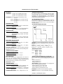
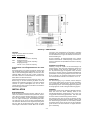
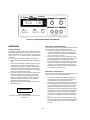
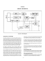
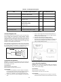
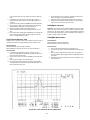
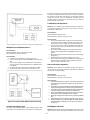
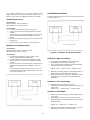
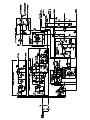
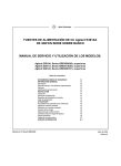
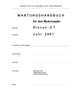
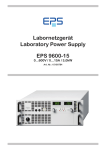
Authorized Distributor
Agilent E361XA
30 WATT-DC-LABORSTROMVERSORGUNGEN
BENUTZER- UND SERVICE-HANDBUCH FÜR FOLGENDE MODELLE:
Agilent E3610A
Agilent E3611A
Agilent E3612A
Inhaltsverzeichnis
SICHERHEITSHINWEISE
ALLGEMEINE INFORMATIONEN
Beschreibung
Spezifikationen und ergänzende Daten
Optionen
Seriennummer und Gültigkeitsbereich des
Handbuchs
INSTALLATION
Eingangskontrolle
Aufstellung und Kühlung
Netzanschluss
Netzkabel
BEDIENUNG
Funktionsprüfung
Betriebsart “Konstantspannung”
Betriebsart “Konstantstrom”
Anschließen der Lasten
Betrieb außerhalb der Spezifikationen
Impulslast
Kapazitive Lasten
Rückstromlast
SERVICE-INFORMATIONEN
Handbuch Agilent-Teilenummer 5959-5304
3-2
3-2
3-2
3-3
3-4
3-4
3-4
3-4
3-4
3-4
3-4
3-5
3-5
3-5
3-5
3-6
3-6
3-6
3-6
3-6
A-1
Oktober 2007
6. Ausgabe
bestimmte Bauteile weiterhin Hochspannung führen. Zur Vermeidung von Stromschlägen müssen das Gerät vom Stromnetz trennen, spannungsführende Bauteile entladen und etwaige externe Spannungen abtrennen, bevor Sie Bauteile berühren.
SICHERHEITSHINWEISE
Die nachstehenden allgemeinen Sicherheitsrichtlinien müssen bei der Bedienung, Wartung oder Reparatur des Gerätes
unbedingt beachtet werden. Das Nichtbeachten der Richtlinien oder besonderer Warnungen an anderen Stellen dieses
Handbuchs verstößt gegen Sicherheitsstandards, Herstellervorschriften und vorgesehene Betriebsweise des Geräts.
Agilent Technologies übernimmt keine Verantwortung für
Schäden, die durch Nichtbeachten dieser Richtlinien entstehen.
SICHERHEITSSYMBOLE
Benutzerhandbuch-Symbol. Dieses Symbol ist an sicherheitsrelevanten Stellen des Gerätes angebracht. Es bedeutet, daß die
diesbezüglichen Hinweise im Bedienungshandbuch
beachtet
werden sollen.
!
Vor dem Anschluss an das Stromnetz
Vergewissern Sie sich, dass das Gerät auf die örtliche Netzspannung eingestellt ist.
oder
Gerät erden.
Dies ist ein Gerät der Schutzklasse 1 (mit Schutzerde-Anschluß). Zur Vermeidung von Stromschlaggefahr müssen das
Chassis und das Gehäuse des Gerätes geerdet werden. Das
Gerät muss über ein dreiadriges Netzkabel an eine Netzsteckdose mit Schutzkontakt angeschlossen werden. Bei Verwendung eines Verlängerungskabels muss eine durchgehende Schutzleiterverbindung vom Gerät bis zur Steckdose
gewährleistet sein. Wenn das Gerät über einen Spartransformator betrieben wird, muss sichergestellt werden, dass der
Bezugspunkt des Spartransformators an den Neutralleiter
(Erde) des Stromnetzes angeschlossen ist.
WARNUNG
Nicht in explosiver Atmosphäre betreiben
Dieses Gerät darf nicht in Gegenwart von entzündbaren Gasen oder Dämpfen betrieben werden.
VORSICHT
VON HOCHSPANNUNGSFÜHRENDEN TEILEN FERN
BLEIBEN!
Das Gehäuse des Gerätes darf nur von einem qualifizierten
Techniker geöffnet werden. Der Austausch von Bauteilen sowie interne Justierungen dürfen nur von einem qualifizierten
Techniker durchgeführt werden. Vor dem Austauschen von
Bauteilen muss das Gerät vom Stromnetz getrennt werden.
Unter Umständen können auch bei abgetrenntem Netzkabel
ALLGEMEINE INFORMATIONEN
Dieses Symbol kennzeichnet den
Erd- (Masse-) anschluss.
Das WARNUNG-Symbol weist
auf Bedienungsschritte, Anwendungen und dergleichen hin, die
bei unsachgemäßer Ausführung
eine Verletzung oder den Tod
des Benutzers zur Folge haben
können. Führen Sie die nach einer WARNUNG beschriebenen
Maßnahmen erst dann aus,
wenn Sie die Warnung inhaltlich
verstanden und die erforderlichen Sicherheitsmaßnahmen getroffen haben.
Das VORSICHT-Symbol weist
auf Bedienungsschritte, Anwendungen und dergleichen hin, bei
deren unsachgemäßer Ausführung das Gerät beschädigt werden kann. Führen Sie die nach
einem solchen Hinweis beschriebenen Maßnahmen erst dann
aus, wenn Sie den Hinweis inhaltlich verstanden und die erforderlichen
Sicherheitsmaßnahmen getroffen haben.
In der Betriebsart “Konstantstrom” können Sie mit dem Drehknopf VOLTAGE den Spannungsbegrenzungswert-einstellen. In der Betriebsart “Konstantspannung” können Sie mit
dem Drehknopf CURRENT den Strombegrenzungswert einstellen. Die Taste CC SET ermöglicht es. mit dem Drehknopf
CURRENT den Strombegrenzungswert einzustellen, ohne
den Ausgang kurzschließen zu müssen.
Beschreibung
Dieses Benutzer- und Service-Handbuch gilt für die Stromversorgungen Agilent E3610A, E3611A und E3612A. Alle
Modelle sind kompakte, vielseitige Stromversorgungen mit
zwei Bereichen, die sich insbesondere für Anwendungen im
Rahmen der Entwicklung von (analogen oder digitalen) ICBaugruppen eignen. Falls nicht ausdrücklich anders vermerkt, beziehen sich die in diesem Handbuch enthaltenen Informationen auf alle drei Modelle. Der gewünschte Ausgangsbereich wird mit der Taste RANGE gewählt. Ausgangsspannung und Ausgangsstrom sind in jedem der beiden Bereiche kontinuierlich einstellbar.
Die Frontplatte enthält numerische Ausgangsspannungs- und
Ausgangsstrom-Anzeigen. Die Ausgangsspannung wird 3 1/
2-stellig (E3611A: dreistellig) angezeigt und der Ausgangsstrom dreistellig. Die Ausgangswertebereiche finden Sie unter “Spezifikationen”.
3-2
Spezifikationen und ergänzende Daten
EINGANGSSPANNUNG:
*ÜBERLASTUNGSSCHUTZ:
115 Vac ± 10%, 47-63 Hz, 0,8 A, 70 W
100 Vac ± 10%, 47-63 Hz, 0,8 A, 70 W
230 Vac ± 10%, 47-63 Hz, 0,4 A, 70 W
Eine ständig wirksame Strombegrenzung schützt die Stromversorgung gegen jede Art von Überlastung einschließlich
Kurzschluss der Ausgangsanschlüsse. In der Betriebsart
“Konstantstrom” wird die Ausgangsspannung von der Konstantspannungsschaltung begrenzt.
AUSGANG:E3610A: 0 bis 8 V, 0 bis 3 A oder 0 bis 15 V,
0 bis 2 A
E3611A: 0 bis 20 V, 0 bis 1,5 A oder 0 bis 35 V,
0 bis 0,85 A
E3612A: 0 bis 60 V, 0 bis 0,5 A oder 0 bis 120V,
bis 0,25 A
*AUSGANGSANSCHLÜSSE:
Die Frontplatte enthält drei Ausgangsanschlüsse. Alle diese
Anschlüsse sind gegenüber der Chassis-Masse isoliert. Ein
beliebiger dieser Anschlüsse kann mit der Chassis-Masse
verbunden werden.
LASTREGELUNG:
*AUSGANGSCHARAKTERISTIKEN
Betriebsart “Konstantspannung”:
Besser als 0,01% + 2 mV für Laststromänderung von Volllast auf Null.
Betriebsart “Konstantstrom”:
Besser als 0,01% + 1 mA für Ausgangsspannungsänderung von Null auf Maximum.
Spannung
PA max
30 Watt
NETZREGELUNG:
Betriebsart “Konstantspannung”:
Besser als 0,01% + 2 mV für beliebige Netzspannungsänderung innerhalb des zulässigen Bereichs.
Betriebsart “Konstantstrom”:
Besser als 0,01% 1 mA für beliebige Netzspannungsänderung innerhalb des zulässigen Bereichs.
Strom
WELLIGKEIT UND RAUSCHEN:
Betriebsart “Konstantspannung”:
Kleiner als 200 uV eff bzw. 2 mV SpitzeSpitze (20 Hz - 20 MHz)
Betriebsart “Konstantstrom”:
Kleiner als 200 uA eff bzw. 1 mA SpitzeSpitze (20 Hz - 20 MHz)
HINWEIS: Im oberen Ausgangsstrombereich sind bei niedrigen Ausgangsströmen Ausgangsspannungen größer als V02
möglich.
E3610A: V 01 = 15 V V02 = 8 V I01 = 2 A l02 = 3 A
E3611A: V01 = 35 V V02 = 20 V I01 = 0,85 A l02 = 1,5 A
E3612A: V 01 = 120 V V02 = 60 V I01 = 0,25 A l02 = 0,5 A
TEMPERATURBEREICH: 0 to 40°C bei Volllast. Im Bereich
von 40°C bis 55°C verringert sich der maximal zulässige Ausgangsstrom um 1%/°C.
*ANZEIGEAUFLÖSUNG
Betriebsart “Konstantspannung”:
Kleiner als (0,02% + 1 mV)/°C.
Betriebsart “Konstantstrom”:
Kleiner als (0,02% + 2 mA)/°C.
Spannung:E3610A
E3611A
E3612A
Strom: E3610A
E3611A
E3612A
EINSCHWINGZEIT:
*ABWÄRTSPROGRAMMIERGESCHWINDIGKEIT: Ma-
*TEMPERATURKOEFFIZIENT:
10 mV
100 mV
100 mV
10 mA
10 mA
1 mA
ISOLATION: ± 240 Vdc
ximaler Zeitbedarf für Ausgangsspannungsänderung von
100% auf 0,1% der maximalen Ausgangsspannung im Leerlauf.
E3610A: maximal 2,5 s
E3611A: maximal 1,0 s
E3612A: maximal 1,5 s
*AUSGANGSDRIFT:
*AUFLÖSUNG: Minimale Schrittweite für Ausgangsspan-
Nach einer Änderung des Ausgangsstroms von voller auf
halbe Last (oder umgekehrt) benötigt die Stromversorgung
weniger als 50 us, um wieder den vorigen Ausgangswert bis
auf eine Abweichung von maximal 10 mV zu erreichen.
Betriebsart “Konstantspannung”:
Kleiner als 0,1% + 5 mV (über 8 Stunden, nach
anfänglichem 30-minütigem Warmlaufen).
Betriebsart “Konstantstrom”: Kleiner als 0,1% + 10 mA (über
8 Stunden, nach anfänglichem 30-minütigem
Warmlaufen).
nungs- oder Ausgangsstromänderung.
E3610A: Spannung 10 mV Strom 5 mA
E3611A: Spannung 10 mV Strom 5 mA
E3612A: Spannung 100 mVStrom 0,5 mA
KÜHLUNG: Das Gerät wird durch Konvektion gekühlt.
GEWICHT: 3,8 kg netto, 4,2 kg einschließlich Verpackung.
ANZEIGEGENAUIGKEIT: ±0,5% + 2 Digits bei 25°C ± 5°C
(HINWEIS) * ERGÄNZENDE DATEN
3-3
Abbildung 1: ABMESSUNGEN
Optionen
versorgung zum Kundendienst zurückschicken, befestigen
Sie daran bitte einen Anhänger mit Angabe des Eigentümers
und der Modellnummer. Fügen Sie außerdem eine kurze Problembeschreibung bei.
Folgende Optionen stehen zur Auswahl:
Option Beschreibung
OEM
Eingangsspannung:
115 Vac +/-10%, 47-63 Hz, einphasig
OE3
Eingangsspannung:
230 Vac +/-10%, 47-63 Hz, einphasig
OE9
Eingangsspannung:
100 Vac +/-10%, 47-63 Hz, einphasig
Es wird empfohlen, als Eingangskontrolle die in diesem
Handbuch beschriebene “Funktionsprüfung” durchzuführen.
Tests zum Verifizieren der Spezifikationen werden im Anhang
beschrieben.
Aufstellung und Kühlung
Abbildung 1 zeigt den Umriss und die Abmessungen der
Stromversorgung. Das Gerät wird einsatzbereit geliefert und
braucht lediglich an das Stromnetz angeschlossen zu werden. Die Stromversorgung ist luftgekühlt. Lassen Sie hinter
dem Gerät so viel Platz, dass ein ungehinderter Kühlluftstrom
gewährleistet ist. Die Umgebungstemperatur sollte nicht mehr
als 40°C betragen. Der maximale Ausgangsstrom verringert
sich bei Temperaturen zwischen 40°C und 55°C um 1%/°C.
Seriennummer und Gültigkeitsbereich des Handbuchs
Stromversorgungen von Agilent Technologies werden durch
eine eindeutige Seriennummer identifiziert. Der Code "MY"
steht für das Herstellungsland Malaysia; die erste der nachfolgenden Ziffern steht für das Jahr (1=1991, 2=1992 usw.),
die beiden nächsten für die Kalenderwoche. Die letzten fünf
Ziffern bilden eine laufende Nummer.
Falls die Seriennummer Ihrer Stromversorgung nicht in dem
Bereich liegt, für den das Handbuch gilt (dieser ist auf der
Titelseite des Handbuchs angegeben), liegt dem Handbuch
eventuell ein gelbes Änderungsblatt bei, das die Unterschiede zwischen Ihrer und der im Handbuch beschriebenen
Stromversorgung beschreibt.
Netzanschluss
INSTALLATION
Netzkabel
Die Stromversorgung ist (je nachdem, welche Netzspannungs-Option bestellt wurde) auf eine der unter “Spezifikationen” angegebenen Netzspannungen eingestellt. Zu jeder
Netzspannungs-Option sind die Eingangsspannungsbereich,
der Eingangsstrom und die Leistungsaufnahme angegeben.
Dieses Gerät wird mit einem dreiadrigen Netzkabel geliefert.
Wenn das Gerät über dieses dreiadrige Kabel an eine
Schutzkontakt-Steckdose angeschlossen wird, ist eine ordnungsgemäße Schutzerdung gewährleistet. Das Gerät darf
auf keinen Fall ohne Schutzerdung betrieben werden.
Eingangskontrolle
Wenn Sie Ihre Stromversorgung erhalten, sollten Sie sie zunächst auf äußerlich erkennbare Transportschäden untersuchen. Wenn ein solcher Schaden erkennbar ist, informieren
Sie sofort den Spediteur und das nächstgelegene Vertriebsbüro von Agilent Technologies. Gewährleistungsinformationen finden Sie auf der inneren vorderen Umschlagseite dieses Handbuchs. Bewahren Sie die Originalverpackung auf für
den Fall, dass Sie die Stromversorgung einmal an Agilent
Technologies zurückschicken müssen. Wenn Sie die Strom-
Die Stromversorgung wird mit einem den Normen des Bestimmungslandes entsprechenden Netzkabel geliefert. Falls
Ihre Stromversorgung irrtümlich mit einem falschen Netzkabel geliefert wurde, setzen Sie sich bitte mit dem nächstgelegenen Vertriebs- und Service-Zentrum von Agilent Technologies in Verbindung.
3-4
Abbildung 2: BEDIENUNGSELEMENTE UND ANZEIGEN
Betriebsart “Konstantspannung”
BEDIENUNG
Wenn Sie die Stromversorgung als Konstantspannungsquelle
betreiben möchten, gehen Sie folgendermaßen vor:
a. Schalten Sie die Stromversorgung ein, und stellen Sie
(vor dem Anschließen der Last) mit dem Zehngang-Potentiometer VOLTAGE die gewünschten Ausgangsspannung ein. Die LED “CV” leuchtet.
b. Drücken Sie die Taste CC SET, und stellen Sie mit dem
Zehngang-Potentiometer CURRENT den maximal zulässigen Ausgangsstrom (Strombegrenzungswert) ein.
Wenn in der Betriebsart “Konstantspannung” eine Laständerung zu einer Überschreitung des Strombegrenzungswertes führt, geht die Stromversorgung automatisch in
die Betriebsart “Konstantstrom” über; die Ausgangsspannung sinkt dann entsprechend ab.
Funktionsprüfung
Nachfolgend wird beschrieben, wie die in Abbildung 2 gezeigten Bedienungselemente und Anzeigen benutzt werden. Außerdem wird ein kurzer Test beschrieben, mit dem Sie überprüfen können, ob die Stromversorgung ordnungsgemäß
funktioniert.
a. Bringen Sie den Netzschalter LINE in die Stellung ON.
b. Wählen Sie mit der Taste RANGE den gewünschten Bereich.
c. Drehen Sie den Drehknopf VOLTAGE gegen den Uhrzeigersinn bis zum Anschlag, und überprüfen Sie, ob die
Ausgangsspannung auf Null zurückgeht. Drehen Sie anschließend den Drehknopf VOLTAGE im Uhrzeigersinn
bis zum Anschlag, und überprüfen Sie, ob die Ausgangsspannung ihren Maximalwert erreicht.
d. Drücken Sie die Taste CC SET und drehen Sie dabei den
Drehknopf CURRENT zuerst gegen den Uhrzeigersinn
bis zum Anschlag und dann im Uhrzeigersinn bis zum
Anschlag; überprüfen Sie dabei, ober der Strombegrenzungswert im Bereich von Null bis zum spezifizierten
Maximalwert eingestellt werden kann.
e. Schließen Sie die Last an die Ausgangsanschlüsse der
Stromversorgung an.
Betriebsart “Konstantstrom”
Wenn Sie die Stromversorgung als Konstantstromquelle betreiben möchten, gehen Sie folgendermaßen vor:
a. Drehen Sie den Drehknopf CURRENT entgegen dem
Uhrzeigersinn bis zum Anschlag (Ausgangsstrom 0 A),
und schalten Sie dann die Stromversorgung ein.
b. Stellen Sie (vor dem Anschließen der Last) mit dem Drehknopf VOLTAGE die maximal zulässige Ausgangsspannung (Spannungsbegrenzungswert) ein. Wenn in der Betriebsart “Konstantstrom” eine Laständerung zu einer
Überschreitung des Spannungsbegrenzungswertes führt,
geht die Stromversorgung automatisch in die Betriebsart
“Konstantspannung” über und begrenzt die Ausgangsspannung auf den programmierten Spannungsbegrenzungswert; der Ausgangsstrom sinkt dann entsprechend
ab.
c. Drücken Sie die Taste CC SET, und stellen Sie mit dem
Drehknopf CURRENT den gewünschten Ausgangsstrom
ein (Die LED “CC” leuchtet erst nach dem Anschließen
der Last).
WARNUNG
Stromschlaggefahr
Trennen Sie das Gerät vor dem Anschließen einer Last vom
Stromnetz ab.
3-5
Anschließen der Last(en)
Kapazitive Last
Der Ausgang der Stromversorgung ist gegenüber der Chassis-Masse isoliert. Einer der beiden Ausgangsanschlüsse
kann mit Chassis-Masse oder mit einer externen Spannung
bis zu 240 V verbunden werden.
Parallel zu den Ausgangsklemmen der Stromversorgung liegt
ein Kondensator, der im Konstantspannungsbetrieb Energiereserven für kurzzeitige Stromspitzen bereitstellt. Eine zusätzliche externe Kapazität parallel zum Ausgang verbessert
zwar die “Standfähigkeit” der Stromversorgung bei pulsförmiger Belastung, beeinträchtigt jedoch die Schutzfunktion der
internen Strombegrenzung. In diesem Fall kann ein starker
Stromimpuls die Last beschädigen, bevor der mittlere Ausgangsstrom so weit angestiegen ist, dass der Überstromschutz anspricht.
Falls Sie mehrere Lasten an der Stromversorgung betreiben
möchten, schließen Sie diese jeweils über separate Leitungspaare an die Ausgangsanschlüsse der Stromversorgung an.
Dadurch werden etwaige Rückwirkungen zwischen den Lasten minimiert, und die Vorzüge der niedrigen Ausgangsimpedanz der Stromversorgung kommen voll zur Geltung. Halten Sie die Lastleitungspaare so kurz wie möglich, und verdrillen Sie sie oder verwenden Sie abgeschirmte Leitungen,
um Störeinstreuungen zu verringern. (Bei Verwendung einer
Abschirmung sollte diese nur stromversorgungsseitig geerdet
werden; lassen Sie das andere Ende der Abschirmung frei).
Rückstromlast
Wenn am Ausgang der Stromversorgung eine aktive Last angeschlossen ist, kann diese u. U. während bestimmter Betriebszustände einen Rückstrom in die Stromversorgung einspeisen. Es muss verhindert werden, dass eine externe
Quelle einen Strom in die Stromversorgung einspeist, da
sonst der Regelkreis eventuell nicht mehr ordnungsgemäß
funktioniert und der Ausgangskondensator der Stromversorgung beschädigt werden kann. Deshalb muss der Ausgang
der Stromversorgung mit einem “Dummy”-Widerstand belastet werden, der dafür sorgt, dass die Stromversorgung während des gesamten Betriebszyklus der Last Strom liefert.
Betrieb außerhalb der Spezifikationen
Mit den Drehknöpfen VOLTAGE und CURRENT können Sie
Ausgangsspannungen bzw. Ausgangsströme einstellen, welche die spezifizierten Maximalwerte um bis zu 5% überschreiten. Die Stromversorgung wird dadurch nicht beschädigt; allerdings ist die Einhaltung der Spezifikationen dann nicht
mehr gewährleistet.
Pulsförmige Belastung
Wenn der Ausgangsstrom den vorgegebenen Grenzwert
überschreitet, geht die Stromversorgung automatisch vom
Konstantspannungsbetrieb in den Strombegrenzungsbetrieb
über. Auch wenn der eingestellte Strombegrenzungswert höher ist als der mittlere Ausgangsstrom, kann es bei pulsförmiger Belastung vorkommen, dass der Strombegrenzungswert
überschritten wird und die Stromversorgung in die Betriebsart
“Konstantstrom” umschaltet. Falls dies unerwünscht ist, stellen Sie den Strombegrenzungswert entsprechend dem Spitzenstrom (und nicht dem mittleren Strom) ein.
3-6
APPENDIX
SERVICE INFORMATION
Figure A-1. Block Diagram
PRINCIPLES OF OPERATION
Throughout this discussion, refer to both the block diagram of Figure A-1
and the schematic diagram at the rear of the manual. The input AC line
voltage is stepped down by the power transformer and applied to the rectifier and filter. The rectifier-filter converts the AC input to raw DC which is
fed to the positive output terminal via parallel series regulator(Q1 and Q3)
and current sampling resistor(R2). The regulator, part of the feedback loop,
is made to alter its conduction to maintain a constant output voltage or current. The voltage developed across the current sampling resistor is the
input to the constant current error amplifier. The constant voltage error
amplifier obtains its input by sampling the output voltage of the supply.
Any changes in output voltage or current are detected, amplified by the
error amplifier and driver and applied to the series regulator in the correct
phase and amplitude to counteract the change in output voltage or current.
Two error amplifiers are included in a CV/CC supply, one for controlling output voltage, the other for controlling output current. Since the
constant voltage amplifier tends to achieve zero output impedance
and alters the output current whenever the load resistance changes,
while the constant current amplifier causes the output impedance to
be infinite and changes the output voltage in response to any load
resistance change, it is obvious that the two amplifiers can not operate simultaneously. For any given value of load resistance, the power
supply must act either as a constant voltage source or as a constant
current source - it can not be both; transfer between these two modes
is accomplished at a value of load resistance equal to the ratio of the
output voltage control setting to the output current control setting.
The reference and bias circuit provides stable reference voltages which
are used by the constant voltage/current error amplifier circuits for comparison purpose. The digital meter circuit provides an indication of output voltage and current for constant voltage or constant current operating modes.
The display power circuit provides voltage which is used by A/D converter and LED drive.
Diode CR3 is connected across the output terminals in reverse polarity. It protects the output electrolytic capacitor and the series regulator
transistor from the effects of s reverse voltage applied across the output terminals.
PERFORMANCE TEST
The following provides the test procedure in high current range for verifying
the unit's compliance with the specifications and characteristics of Table in
page 1-3. The same test procedure may be applied to low current range.
Test Equipment Required
The following Table lists the equipment required to perform the tests
and adjustments. You can separately identify the equipment for performance tests, or calibration in the USE column of the Table.
A-1
Table A-1. Test Equipment Required
TYPE
REQUIRED CHARACTERISTICS
USE
RECOMMENDED MODEL
Oscilloscope
Sensitivity: 1 mV
Bandwidth: 20 MHz/100 MHz
P
RMS Voltmeter
True rms, 10 MHz bandwidth
P
Multimeter
Resolution: 0.1 mV
Accuracy: 0.01%
P, A
Agilent 34401A
Electronic Load
Voltage Range : 240 Vdc
Current Renge : 10 Adc
Open and short switches
Transient on/off
P, A
Agilent 6063B
Load Resistor(For high current range)
2.6 ohm 50 W, 13.3 ohm 50 W, 120 ohm
50 W
P
Current Sampling Resistor
0.1 ohm 0.1% 10 W, 1 ohm 1% 10 W
P, A
* P = Performance testing
Constant Voltage(CV) Test
The measuring device must be connected as close to the output terminals as possible when measuring the output impedance, transient
response, regulation, or ripple of the power supply in order to achieve
valid measurements. A measurement made across the load includes the
impedance of the leads to the load and such leed lengths can have an
impedance several orders of magnitude greater than the supply output
impedance, thus invalidating the measurement.
Agilent 54602A
A = Calibration adjustments.
c. Turn up output voltage to the full rated value (E3610A: 8.0 V,
E3611A: 20 V, E3612A: 60 V) as read on the digital voltmeter.
Then input on the electronic load.
d. Record the output voltage at the digital voltmeter.
e. Operate the electronic load in Open(Input Off) mode.
f. Record the output voltage again immediately. The readings’ difference during the immediate change should not more than
0.01% of output voltage plus 2 mV.
When performance measurements are made at the front terminals,
the load should be plugged into the front of the terminals at (B), while
the monitoring device is connected to a small lead or bus wire
inserted through the hole in the neck of the binding post at (A).
Load Effect(Load Regulation)
Definition: CV Load Effect is the immediate change in dc output voltage when load resistance changes from open circuit to full load or
from full load to open circuit.
Test Parameters:
Measured Variable: Output Voltage
Expected Results: Less than 0.01% plus 2 mV
Test Procedure:
a. Connect the test equipment as shown in Figure A-2. Operate
the electronic load in constant current mode and set its current
to the full rated value of the power supply (E3610A: 3.0 A,
E3611A: 1.5 A, E3612A: 0.5 A). Input off the electronic load.
b. Turn the unit's power on and turn CURRENT control fully clockwise.
A-2
Figure A-2. Basic Test Setup
Source Effect(Line Regulation)
Definition: Source effect is the immediate change in dc output voltage when the ac input voltage changes from a minimum to maximum
value (± 10%of nominal voltage).
Test Parameter:
Measured Variable: Output Voltage
Expected Results: Less than 0.01% plus 2 mV
Test Procedure:
a. Connect the test equipment as shown in Figure A-2. Operate
the electronic load in constant current mode and set its current
b.
c.
d.
e.
f.
g.
to the full rated value of power supply. Input off the electronic
load.
Connect the unit to the ac power line through a variable
autotransformer which is set for low line voltage (104 Vac for
115 Vac).
Turn the unit’s power on and turn CURRENT control fully clock-wise.
Turn up output voltage to the full rated values as read on the
digital voltmeter. Then input on the electronic load.
Record the output voltage at the digital voltmeter.
Adjust autotransformer to high line voltage (127 Vac for 115
Vac).
Record the output voltage again immediately. The readings’ difference during the immediate change should not more than
0.01% of output voltage plus 2 mV.
e. Set the oscilloscope for ac coupling, internal sync and lock on
either the positive or negative load transient.
f. Adjust the oscilloscope to display transients as in Figure A-3.
g. Check that the pulse width of the transients at 10 mV from the
base line is no more than 50 usec as shown.
PARD(Ripple and Noise)
Definition: Periodic and random deviation(PARD) in the unit's output
ripple and noise combine to produce a residual ac voltage superimposed on the dc output voltage. Constant voltage PARD is specified
as the root-mean-square(rms) or peak-to-peak(pp) output voltage in a
frequency range of 20 Hz to 20 MHz.
PARD(RMS) Measurement
Load Transient Recovery Time
Definition: This is the time for the output voltage to return to within a
specified bend around its voltage following a step change in load.
Test Parameters:
Measured Variable: Output Voltage Transients
Expected Results: Less than 50 usec (at 10 mV from base line)
Test Procedure:
a. Connect the test equipment as shown in Figure A-2, but
replace the DVM with the oscilloscope. Operate the electronic
load in constant current mode.
b. Turn the unit's power on and turn CURRENT control fully clockwise.
c. Turn up output voltage to the full rated value.
d. Set the electronic load to transient operation mode between
one half of unit's full rated value and unit's full rated value at a 1
KHz rate with 50% duty cycle.
Test Parameter:
Measured Variable: Output Voltage(rms)
Expected Results: Less than 200 uV rms
Test Procedure:
a. Connect the test equipment as shown in Figure A-4.
b. Turn the unit's power on and turn CURRENT control fully clockwise.
c. Turn up output voltage to the full rated value. Check that the
unit's CV indicator remains lighted. Reduce VOLTAGE control if
not lighted.
d. Check that the rms noise voltage at the true rms voltmeter is no
more than 200 uV.
Figure A-3. Load Transient Recovery Waveform
A-3
the load current is fed to the extremes of the wire leading to the resistor while the sampling terminals are located as close as possible to
the resistance portion itself. Generally, any current sampling resistor
should be of the low noise, low temperature coefficient type end
should be used at no more than 5% of its rated power so that its temperature rise will be minimized.
Load Effect(Load Regulation)
Definition: CC Load Effect is the immediate change in dc output current when load resistance changes from short circuit to full load or
from full load to short circuit.
Test Parameter:
Measured Variable: Output Current
Expected Results: Less than 0.01% plus 1 mA
Figure A-4. RMS Measurement Test Setup
PARD(Peak-to-Peak) Measurement
Test Parameter:
Measured Variable: Output voltage(peak-to-peak)
Expected Results: Less than 2 mV p-p
Test Procedure:
a. Connect the test equipment as shown in Figure A-5.
b. Turn the unit's power on and turn CURRENT control fully clockwise.
c. Turn up output voltage to the full rated value. Check that the
unit's CV Indicator remains lighted. Reduce VOLTAGE control
if not lighted.
d. Set the oscilloscope to AC mode and bandwidth to 20 MHz.
e. Check that the peak-to-peak noise is no more than 2 mV.
Test Procedure:
a. Connect the DVM across Rs in Figure A-2. Operate the electronic load in constant voltage mode and set its voltage to the
full rated value of power supply. Input off the electronic load.
b. Turn the unit's power on and turn VOLTAGE control fully clock
wise and current control to the full rated value. Then input on
the electronic load.
c. Check that the AMPS display reads full rated values and CC
indicator remains lighted. Reduce CURRENT control if not
lighted.
d. Record the voltage across Rs and convert it to current through
dividing by Rs .
e. Operate the electronic load in short(input short mode).
f. Record voltage across Rs again immediately. The readings’ difference during the immediate change should not more than
0.01% of output current plus 1 mA.
Source Effect(Line Regulation)
Definition: Source Effect is the immediate change in dc output current when the ac input voltage changes from the minimum to maximum
val ue(± 10% of nominal voltage).
Test Parameter:
Measured Variable: Output Current
Expected Results: Less than 0.01% plus 1 mA
Figure A-5. Peak-to-Peak Measurement Test Setup
Constant Current(CC) Tests
For output current measurements the current sampling resistor must
be treated as a four terminal device. In the manner of a meter shunt,
Test Procedure:
a. Connect the DVM across Rs in Figure A-2. Operate the electronic load
in constant voltage mode and set its voltage to the full rated value of
power supply.
b. Connect the unit to the ac power line through a variable autotransformer that
set for low line voltage(104 Vac for 115 Vec). Input off the electronic load.
c. Turn the unit's power on and turn VOLTAGE control fully clock wise and output current to the full rated value. Then input on the electronic load.
d. Check that the AMPS display reads full rated values and CC indicator
remains lighted. Reduce CURRENT control if not lighted.
e. Record output voltage across Rs and convert it to current through dividing
by Rs.
f. Adjust autotransformer to the high line voltage(127 Vac for 115 Vac).
g. Record the voltage across Rs again immediately. The readings’ difference
during the immediate change should not more than 0.01% of output current plus 1 mA.
PARD(Ripple and Noise)
Definition: Periodic and random deviation(PARD) in the unit's output
ripple and noise combine to produce a residual ac current as well as
A-4
an ac voltage superimposed on the dc output. Constant Current
PARD is specified as the root-mean-square(rms) output current in e
frequency range of 20 Hz to 20 MHz with the unit in CC operation.
PARD(RMS) Measurement
CALIBRATION PROCEDURE
To calibrate ammeter and full scale current, connect test equipments
as shown in Figure A-7.
Test Parameter:
Measured Variable: Output Current(rms)
Expected Results: Less than 200 uA rms
Test Procedure:
a. Connect the test equipment as shown in Figure A-6.
b. Turn the unit's power on and turn the VOLTAGE control fully
clockwise.
c. Turn up output current to the full rated value. Check that the CC
indicator remains lighted. Reduce CURRENT control if not
lighted.
d. Record rms voltage across Rs and convert it to current through
dividing by Rs.
e. Check that the rms noise current is no more than 200 uA.
PARD(Peak-to-Peak) Measurement
Test Parameter:
Measured Variable: Output Current(peak-to-peak)
Expected Results: Less than 1 mA p-p
Figure A-7. Calibration in High Current Range
Test Procedure:
a. Connect the test equipment as shown in Figure A-6, but
replace the RMS voltmeter with oscilloscope.
b. Set the oscilloscope to AC mode and bandwidth to 20 MHz.
c. Turn the unit's power on and turn the VOLTAGE control fully
clockwise.
d. Turn up output current to the full rated value. Check that the CC
indicator remains lighted. Reduce CURRENT control if not
lighted.
e. Record peak-to-peak voltage across Rs and convert it to current through dividing by Rs . Check that the peak-to-peak noise
current is no more than 1 mA.
Calibration in High Current Range
a. Turn VOLTAGE and CURRENT control fully clockwise.
b. Set RANGE push button to high current range.
c. Turn on power supply and adjust R31 so that DVM indicates
exactly as follows (5% over rated current):
E3610A: 0.315 V
E3611A: 0.158 V
E3612A: 0.053 V
d. Adjust R3 on the display board so that the displayed value on
the front panel is equal to DVM value divided by Rs.
e. While depressing CC SET push button, adjust R20 so that the
displayed value on the front panel is equal to DVM value
divided by Rs.
Calibration in Low Current Range
a. Set RANGE push button to low current range.
b. Adjust R32 so that DVM indicates exactly as follows (5% over
rated current).
E3610A: 0.21 V E3611A: 0.089 V E3612A: 0.026 V
Calibration of VOLTS Meter
a. Disconnect the current shunt(Rs) and connect DVM across output of supply.
b. Set RANGE push button to low current range at no load.
c. Adjust VOLTAGE control till DVM indicates exactly as follows
(full rated voltage):
E3610A: 15 V
Figure A-6. RMS Measurement Test setup
E3611A: 35 V
E3612A: 120 V
d. Adjust R10 on the display board so that the value of the front
panel display is the same as the value of DVM.
A-5
s1
CERTIFICATION
Agilent Technologies certifies that this product met its published specifications at time of shipment from the factory. Agilent
further certifies that its calibration measurements are traceable to the United States National Institute of Standards and Technology (formerly National Bureau of Standards), to the extent allowed by that organization's calibration facility, and to the calibration facilities of other International Standards Organization members.
WARRANTY
This Agilent Technologies hardware product is warranted against defects in material and workmanship for a period of one
year from date of delivery. Agilent software and firmware products, which are designated by Agilent for use with a hardware
product and when properly installed on that hardware product, are warranted not to fail to execute their programming instructions due to defects in material and workmanship for a period of 90 days from date of delivery. During the warranty period,
either Agilent or Agilent Technologies will, at its option, either repair or replace products which prove to be defective. Agilent
does not warrant that operation the software, firmware, or hardware shall be uninterrupted or error free.
For warranty service, with the exception of warranty options, this product must be returned to the nearest service center designated by Agilent. Customer shall prepay shipping charges by (and shall pay all duty and taxes) for products returned to Agilent for warranty service. Except for the products returned to Customer from another country, Agilent shall pay for return of
products to Customer.
Warranty services outside the country of initial purchase are included in Agilent's product price, only if Customer pays Agilent
international prices (defined as destination local currency price, or U.S. or Geneva Export price).
If Agilent is unable, within a reasonable time, to repair or replace any product to condition as warranted, the Customer shall
be entitled to a refund of the purchase price upon return of the product to Agilent.
The warranty period begins on the date of delivery or on the date of installation if installed by Agilent.
LIMITATION OF WARRANTY
The foregoing warranty shall not apply to defects resulting from improper or inadequate maintenance by the Customer, Customer-supplied software or interfacing, unauthorized modification or misuse, operation outside of the environmental specifications for the product, or improper site preparation and maintenance. TO THE EXTENT ALLOWED BY LOCAL LAW, NO
OTHER WARRANTY IS EXPRESSED OR IMPLIED. AND AGILENT SPECIFICALLY DISCLAIMS THE IMPLIED WARRANTIES OF MERCHANTABILITY AND FITNESS FOR A PARTICULAR PURPOSE.
For consumer transactions in Australia and New Zealand:
The warranty terms contained in this statement, except to the extent lawfully permitted, do not exclude, restrict or modify and
are in addition to the mandatory rights applicable to the sale of this product to you.
EXCLUSIVE REMEDIES
TO THE EXTENT ALLOWED BY LOCAL LAW, THE REMEDIES PROVIDED HEREIN ARE THE CUSTOMER'S SOLE AND
EXCLUSIVE REMEDIES. AGILENT SHALL NOT BE LIABLE FOR ANY DIRECT, INDIRECT, SPECIAL, INCIDENTAL, OR
CONSEQUENTIAL DAMAGES, WHETHER BASED ON CONTRACT, TORT, OR ANY OTHER LEGAL THEORY.
ASSISTANCE
The above statements apply only to the standard product warranty. Warranty options, extended support contacts, product
maintenance agreements and customer assistance agreements are also available. Contact your nearest Agilent Technologies Sales and Service office for further information on Agilent's full line of Support Programs.
DECLARATION OF CONFORMITY
According to ISO/IEC Guide 22 and CEN/CENELEC EN 45014
Manufacturer’s Name and Addresss
Responsible Party
Agilent Technologies, Inc.
550 Clark Drive, Suite 101
Budd Lake, New Jersey 07828
USA
Alternate Manufacturing Site
Agilent Technologies (Malaysia) Sdn. Bhd
Malaysia Manufacturing
Bayan Lepas Free Industrial Zone, PH III
11900 Penang,
Malaysia
Declares under sole responsibility that the product as originally delivered
Product Name:
a) Single Output dc Power Supply (dual range)
b) Single Output dc Power Supply (single range)
c) Single Output System Power Supply
d) Multiple Output dc Power Supply
e) Multiple Output System dc Power Supply
Model Number:
a) E3610A, E3611A, E3612A
b) E3614A, E3615A, E3616A, E3617A
c) E3632A
d) E3620A, E3630A
e) E3631A
Product Options:
This declaration covers all options of the above product(s).
Complies with the essential requirements of the Low Voltage Directive 73/23/EEC and the EMC
Directive 89/336/EEC (including 93/68/EEC) and carries the CE Marking accordingly .
EMC Information
ISM Group 1 Class A Emissions
As detailed in
Electromagnetic Compatibility (EMC), Certificate of Conformance Number
CC/TCF/00/102 based on Technical Construction File (TCF) ANJ12, dated
Dec.20, 2000.
Assessed by:
Celestica Ltd, Appointed Competent Body
Westfields House, West Avenue
Kidsgrove, Stoke-on-Trent
Straffordshire, ST7 1TL
United Kingdom
Safety Information
and Conforms to the following safety standards.
IEC 61010-1:2001 / EN 61010-1:2001
CSA C22.2 No. 1010.1:1992
This DoC applies to above-listed products placed on the EU market after:
January 1, 2004
Date
Bill Darcy/ Regulations Manager
For further information, please contact your local Agilent Technologies sales office, agent or distributor, or
Agilent Technologies Deutschland GmbH, Herrenberger Straβe 130, D71034 Böblingen, Germany
Revision: B.00.00
Issue Date: Created on 11/24/2003 3:10
PM
Document No. KIO_10-32.11.24doc.doc