1
Agilent E361XA 30W BENCH SERIES DC POWER SUPPLIES
OPERATING AND SERVICE MANUAL FOR MODELS:
Agilent E3610A
Agilent E3611A
Agilent E3612A
6CDNGQH%QPVGPVU
5#('6;57//#4;
)'0'4#.+0(14/#6+10
&GUETKRVKQP
5RGEKHKECVKQPUCPF%JCTCEVGTKUVKEU
1RVKQPU
+PUVTWOGPVU+FGPVKHKECVKQP
+056#..#6+10
+PURGEVKQP
.QECVKQPCPF%QQNKPI
+PRWV2QYGT4GSWKTGOGPVU
2QYGT%QTF
12'4#6+10
6WTP1P%JGEMQWV2TQEGFWTG
%QPUVCPV8QNVCIG1RGTCVKQP
%QPUVCPV%WTTGPV1RGTCVKQP
%QPPGEVKPI.QCFU
1RGTCVKQP$G[QPF4CVGF1WVRWV
2WNUG.QCFKPI
%CRCEKVKXG.QCFU
4GXGTUG%WTTGPV.QCFKPI
5'48+%'+0(14/#6+10
#
April 2000
Edition 5
Manual Part No. 5959-5304
1-1
SAFETY SUMMARY
KEEP AWAY FROM LIVE CIRCUITS.
Operating personnel must not remove instrument covers.
Component replacement and internal adjustments must be
made by qualified service personnel. Do not replace components with power cable connected. Under certain conditions,
dangerous voltages may exist even with the power cable
removed. To avoid injuries, always disconnect power, discharge circuits and remove external voltage sources before
touching components.
The following general safety precautions must be observed
during all phases of operation, service, and repair of this
instrument. Failure to comply with these precautions or with
specific warnings elsewhere in this manual violates safety
standards of design, manufacture, and intended use of the
instrument. Agilent Technologies assumes no liability for the
customer’s failure to comply with these requirements.
SAFETY SYMBOLS
Before Applying Power
Verify that the product is set to match the available line
voltage.
Instruction manual symbol; the
product will be marked with this
symbol when it is necessary for
the user to refer to the instruction
manual.
!
Ground The Instrument.
This product is a Safety Class I instrument (provided with a
protective earth terminal). To minimize shock hazard, the
instrument chassis and cabinet must be connected to an
electrical ground. The instrument must be connected to the
ac power supply mains through a three-conductor power
cable, with the third wire firmly connected to an electrical
ground (safety ground) at the power outlet. Any interruption of
the protective(grounding) conductor or disconnection of the
protective earth terminal will cause a potential shock hazard
that could result in personal injury. If the instrument is to be
energized via an external autotransformer for voltage reduction, be certain that the autotransformer common terminal is
connected to the neutral (earthed pole) of the ac power lines
(supply mains).
or
WARNING
CAUTION
Do Not Operate In An Explosive Atmosphere
Do not operate the instrument in the presence of flammable
gases or fumes.
Regulatory Information for Canada
This ISM device complies with Canadian ICES-001.
Cet appareil ISM est conforme à la norme NMB-001 du Canada.
GENERAL INFORMATION
Indicate earth(ground) terminal.
The WARNING sign denotes a
hazard. It calls attention to a procedure, practice, or the like, which, if
not correctly performed or adhered
to, could result in personal injury.
Do not proceed beyond a WARNING sign until the indicated conditions are fully understood and
met.
The CAUTION sign denotes a hazard. It calls attention to an operating
procedure, or the like, which, if not
correctly performed or adhered to,
could result in damage to or destruction of part or all of the product. Do
not proceed beyond CAUTION sign
until the indicated conditions are fully
understood and met.
The front panel VOLTAGE control can be used to establish
the voltage limit when the supply is used as a constant current source and the CURRENT control can be used to establish the output current limit when the supply is used as a
constant voltage source. The CC SET push button allows the
current limit value to be conveniently set using the CURRENT
control without shorting the output.
Description
This operating and service manual covers three dual range
Agilent power supplies, E3610A, E3611A, and E3612A. All
models are compact, general purpose bench supplies that
are particularly useful for powering developmental IC circuits,
both linear and digital. Unless stated otherwise, all information in this manual applies equally to all three models. The
desired output range is selected by the front panel RANGE
push button. The output can be continuously adjusted for voltage and current throughout either output range.
The front panel includes a digital voltmeter/ammeter. A 3 1/2
digit (E3611A 3 digit) voltage display and 3 digit current display accurately show the output voltage and current respectively. The output ratings for each model are shown in the
Specifications Table.
1-2
Specifications and Supplemental Characteristics
INPUT: 115 Vac 10%, 47-63 Hz, 0.8 A, 70 W
output voltage in constant current operation.
100 Vec 10%, 47-63 Hz, 0.8 A, 70 W
230 Vac 10%, 47-63 Hz, 0.4 A, 70 W
*OUTPUT TERMINALS:
Three output terminals are provided on the front panel. They
are isolated from the chassis and either the positive or negative terminal may be connected to the ground terminal.
OUTPUT: E3610A: 0 to 8 V, 0 to 3 A or 0 to 15 V,
0 to 2 A
E3611A: 0 to 20 V, 0 to 1.5 A or 0 to 35 V,
0 to 0.85 A
E3612A: 0 to 60 V, 0 to 0.5 A or 0 to 12OV,
to 0.25 A
*OUTPUT CHARACTERISTICS
LOAD REGULATION:
Constant Voltage - Less than 0.01% plus 2 mV for a full load
to no load change in output current.
Constant Current - Less than 0.01% plus 1 mA for a zero to
maximum change in output voltage.
LINE REGULATION:
Constant Voltage - Less than 0.01% plus 2 mV for any line
voltage change within the input rating.
Constant Current - Less than 0.01% plus 1 mA for any line
voltage change within the input rating.
RIPPLE AND NOISE:
NOTE: Output voltages higher than V02 are possible at low
current when the high current range is selected.
E3610A: V01 = 15 V V02 = 8 V I01 = 2 A l02 = 3 A
E3611A: V01 = 35 V V02 = 20 V I01 = 0.85 A l02 = 1.5 A
E3612A: V01 = 120 V V02 = 60 V I01 = 0.25 A l02 = 0.5 A
Constant Voltage - Less than 200 uV rms and 2 mV peak to
peak(20 Hz - 20 MHz)
Constant Current - Less than 200 uA rms and 1 mA peak to
peak(20 Hz - 20 MHz)
TEMPERATURE RANGE: 0 to 40C for full rated output.
Derate current 1% per degree C between 40C-55C
*METER RESOLUTION
Voltage: E3610A
E3611A
E3612A
Current: E3610A
E3611A
E3612A
*TEMPERATURE COEFFICIENT:
Constant Voltage - Less than 0.02% plus 1 mV per degree C.
Constant Current - Less than 0.02% plus 2 mA per degree C.
TRANSIENT RESPONSE TIME:
Less than 50 usec for output recovery to within 10 mV following a change in output current from full load to half load, or
vice versa.
10 mV
100 mV
100 mV
10 mA
10 mA
1 mA
*DOWN PROGRAMMING SPEED: Maximum time for output voltage to change between 100% to 0.1% of maximum
rated output voltage at NO LOAD condition.
E3610A: maximum 2.5 sec
E3611A: maximum 1.0 sec
E3612A: maximum 1.5 sec
ISOLATION: 240 Vdc
*OUTPUT DRIFT:
Constant Voltage - Less than 0.1% plus 5 mV total drift for 8
hours after an initial warm-up of 30 minutes.
Constant Current - Less than 0.1% plus 10 mA total drift for 8
hours after an initial warm-up of 30 minutes.
*RESOLUTION: Minimum output voltage or current change
that can be obtained using panel controls.
E3610A: Voltage 10 mV
Current 5 mA
E3611A: Voltage 10 mV
Current 5 mA
E3612A: Voltage 100 mV Current 0.5 mA
METER ACCURACY: 0.5% + 2 counts at 25C 5C
COOLING: Convection cooling is employed.
*OVERLOAD PROTECTION:
WEIGHT: 8.4 Ibs/3.8 Kg net, 9.3 Ibs/4.2 Kg shipping.
A continuously acting constant current circuit protects the
power supply for all overloads including a direct short placed
across the terminals. The constant voltage circuit limits the
(NOTE) * SUPPLEMENTAL CHARACTERISTICS
1-3
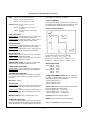
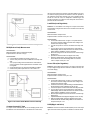
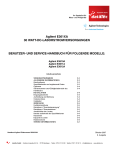
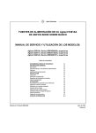
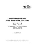
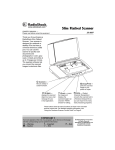
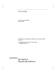
Figure 1: OUTLINE DIAGRAM
Options
The "Turn-On Checkout Procedure" in this manual can be
used as an incoming inspection check to verify that the supply is operational. See the appendix for tests that verify the
supply's specifications.
The following options are available with this instrument.
Option
0EM:
0E3:
0E9:
1CM:
Description
115 Vac ± 10%, 47-63 Hz Input
230 Vac ± 10%, 47-63 Hz Input
100 Vac ± 10%, 47-63 Hz Input
Rack Mount Kit (Agilent p/n 5063-9767)
Location And Cooling
Figure 1 shows the outline shape and dimensions of the unit.
It is shipped ready for bench operation after connection to an
ac power source. The supply is air cooled. Sufficient space
should be allotted so that a free flow of cooling air can reach
the rear of the instrument when it is in operation. It should be
used in an area where the ambient temperature does not
exceed 40 degrees C. The current derates 1% per degree C
between 40°C-55°C.
Instrument Identification
Agilent Technologies power supplies are identified by one
serial number. The letter "KR" designates Korea as the country of manufacture, the first digit indicates the year (1 = 91, 2
= 92, etc), the second two digits indicate the week, and the
last five digits of the serial number are a different sequential
number assigned to each power supply.
Input Power Requirements
Depending on the line voltage option ordered, the supply is
ready to be operated from one of the power sources listed in
the Specification Table. The input voltage range, and the
input current and power at high line voltage and full load is
listed for each option.
If a yellow Change Sheet is supplied with this manual, its purpose is to explain any differences between your instrument
and the instrument described in this manual. The Change
Sheet may also contain information for correcting errors in the
manual.
Power Cord
INSTALLATION
This instrument is equipped with a three conductor power
cable. The third conductor is the ground conductor and when
the cable is plugged into an appropriate receptacle, the
instrument is grounded. The offset pin on the power cable
three prong connector is the ground connection. In no event
should this instrument be operated without an adequate cabinet ground connection.
Inspection
When you receive your power supply, inspect it for any obvious damage that may have occurred during shipment. If there
is damage, notify the carrier and the nearest Agilent Sales
Office immediately. Warranty information is printed on the
inside front cover of this manual. Save the shipping carton
and packing materials in case the supply has to be returned
to Agilent Technologies in the future. If you return the supply
for service, attach a tag identifying the owner and model number. Also include e brief description of the problem.
The power supply was shipped with a power cord for the type
of outlet used at your location. If the appropriate cord was not
included, contact your nearest Agilent Sales Office to obtain
the correct cord.
1-4
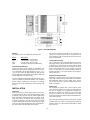
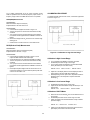
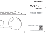
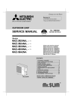
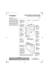
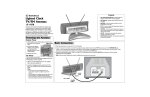
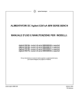
Figure 2: FRONT PANEL CONTROLS AND INDICATORS
Constant Current Operation
OPERATION
To set up a power supply for a constant current operation,
proceed as follows:
Turn-On Checkout Procedure
The following checkout procedure describes the use of the
front panel controls and indicators illustrated in Figure 2 and
ensures that the supply is operational:
a. Push LINE button to ON.
b. Set RANGE push button to desired range.
c. Turn VOLTAGE control fully counter clockwise to ensure
that output decreases to 0 Vdc than fully clockwise to
ensure that output voltage increases to the maximum output voltage.
d. While depressing CC SET push button, turn the CURRENT control fully counter clockwise and than fully clockwise to ensure that the current limit value can be set from
zero to maximum rated value.
e. Connect load to output terminals.
a. Turn CURRENT control fully counter clockwise to ensure
that output decreases to 0 A, and than turn on power supply.
b. Adjust VOLTAGE control (no load connected) for maximum output voltage allowable (voltage limit), as determined by load conditions. During actual operation, if a
load change causes the voltage limit to be exceeded, the
power supply will automatically cross- over to constant
voltage operation at the preset voltage limit and output
current will drop proportionately.
c. Adjust CURRENT control for desired output current while
depressing CC SET button (CC LED will not light until the
supply is loaded)
Connecting Loads
The output of the supply is isolated from earth ground. Either
output terminal may be grounded or the output can be floated
up to 240 volts off ground.
WARNING
Each load should be connected to the power supply output
terminals using separate pairs of connecting wires. This will
minimize mutual coupling effects between loads and will
retain full advantage of the low output impedance of the
power supply. Each pair of connecting wires should be as
short as possible and twisted or shielded to reduce noise
pickup (lf a shield is used, connect one end to the power supply ground terminal and leave the other end unconnected.).
Shock Hazard
Disconnect ac power before making
output terminal connections.
Constant Voltage Operation
To set up a power supply for a constant voltage operation,
proceed as follows:
a. Turn on power supply and adjust 10-turn VOLTAGE control for desired output voltage (output terminals open). CV
LED should light.
b. While depressing CC SET push button, adjust 10-turn
CURRENT control for maximum output current allowable
(current limit). During actual operation, if a load change
causes the current limit to be exceeded, the power supply
will automatically crossover to constant current mode and
output voltage will drop proportionately.
Operation Beyond Rated Output
The output controls can adjust the voltage or current to values
above (up to 5%) the rated output as indicated on the front
panel display. Although the supply can be operated in the 5%
overrange region without being damaged, it can not be guaranteed to meet all of its performance specifications in this
region.
1-5
Pulse Loading Considerations
but will decrease the safety provided by the current limiting
circuit. A high-current pulse may damage load components
before the average output current is Iarge enough to cause
the current limiting circuit to operate.
The power supply will automatically cross over from constantvoltage to constant-current operation in response to an
increase (over the preset limit) in the output current. Although
the preset limit may be set higher than the average output
current, high peak currents (as occur in pulse loading) may
exceed the preset current limit and cause crossover to occur.
If this crossover limiting is not desired, set the preset limit for
the peak requirement and not the average.
Reverse Current Loading
Active loads connected to the power supply may actually
deliver a reverse current to the power supply during a portion
of its operating cycle. An external source can not be allowed
to pump current into the supply without loss of regulation and
possible damage to the output capacitor. To avoid these
effects, it is necessary to preload the supply with a dummy
load resistor so that the power supply delivers current through
the entire operating cycle of the load devices.
Capacitive Loads
An internal capacitor, across the output terminals of the
power supply, helps to supply high-current pulses of short
duration during constant voltage operation. Any capacitance
added externally will improve the pulse current capability,
1-6
APPENDIX
SERVICE INFORMATION
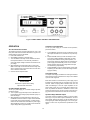
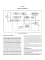
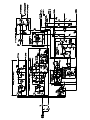
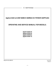
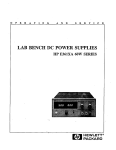
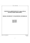
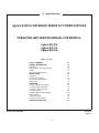
Figure A-1. Block Diagram
PRINCIPLES OF OPERATION
Throughout this discussion, refer to both the block diagram of Figure A-1
and the schematic diagram at the rear of the manual. The input AC line
voltage is stepped down by the power transformer and applied to the rectifier and filter. The rectifier-filter converts the AC input to raw DC which is
fed to the positive output terminal via parallel series regulator(Q1 and Q3)
and current sampling resistor(R2). The regulator, part of the feedback loop,
is made to alter its conduction to maintain a constant output voltage or current. The voltage developed across the current sampling resistor is the
input to the constant current error amplifier. The constant voltage error
amplifier obtains its input by sampling the output voltage of the supply.
Any changes in output voltage or current are detected, amplified by the
error amplifier and driver and applied to the series regulator in the correct
phase and amplitude to counteract the change in output voltage or current.
Two error amplifiers are included in a CV/CC supply, one for controlling output voltage, the other for controlling output current. Since the
constant voltage amplifier tends to achieve zero output impedance
and alters the output current whenever the load resistance changes,
while the constant current amplifier causes the output impedance to
be infinite and changes the output voltage in response to any load
resistance change, it is obvious that the two amplifiers can not operate simultaneously. For any given value of load resistance, the power
supply must act either as a constant voltage source or as a constant
current source - it can not be both; transfer between these two modes
is accomplished at a value of load resistance equal to the ratio of the
output voltage control setting to the output current control setting.
The reference and bias circuit provides stable reference voltages which
are used by the constant voltage/current error amplifier circuits for comparison purpose. The digital meter circuit provides an indication of output voltage and current for constant voltage or constant current operating modes.
The display power circuit provides voltage which is used by A/D converter and LED drive.
Diode CR3 is connected across the output terminals in reverse polarity. It protects the output electrolytic capacitor and the series regulator
transistor from the effects of s reverse voltage applied across the output terminals.
PERFORMANCE TEST
The following provides the test procedure in high current range for verifying
the unit's compliance with the specifications and characteristics of Table in
page 1-3. The same test procedure may be applied to low current range.
Test Equipment Required
The following Table lists the equipment required to perform the tests
and adjustments. You can separately identify the equipment for performance tests, or calibration in the USE column of the Table.
A-1
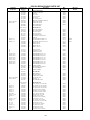
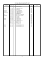
Table A-1. Test Equipment Required
TYPE
REQUIRED CHARACTERISTICS
USE
RECOMMENDED MODEL
Oscilloscope
Sensitivity: 1 mV
Bandwidth: 20 MHz/100 MHz
P
RMS Voltmeter
True rms, 10 MHz bandwidth
P
Multimeter
Resolution: 0.1 mV
Accuracy: 0.01%
P, A
Agilent 34401A
Electronic Load
Voltage Range : 240 Vdc
Current Renge : 10 Adc
Open and short switches
Transient on/off
P, A
Agilent 6063B
Load Resistor(For high current range)
2.6 ohm 50 W, 13.3 ohm 50 W, 120 ohm
50 W
P
Current Sampling Resistor
0.1 ohm 0.1% 10 W, 1 ohm 1% 10 W
P, A
* P = Performance testing
Constant Voltage(CV) Test
The measuring device must be connected as close to the output terminals as possible when measuring the output impedance, transient
response, regulation, or ripple of the power supply in order to achieve
valid measurements. A measurement made across the load includes the
impedance of the leads to the load and such lead lengths can have an
impedance several orders of magnitude greater than the supply output
impedance, thus invalidating the measurement.
Agilent 54602A
A = Calibration adjustments.
c. Turn up output voltage to the full rated value (E3610A: 8.0 V,
E3611A: 20 V, E3612A: 60 V) as read on the digital voltmeter.
d. Record the output voltage at the digital voltmeter.
e. Operate the electronic load in Open(Input Off) mode.
f. When the reading settles, record the output voltage again.
Check that the two recorded readings differ no more than
0.01% of output voltage plus 2 mV.
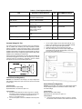
When performance measurements are made at the front terminals, the
load should be plugged into the front of the terminals at (B), while the
monitoring device is connected to a small lead or bus wire inserted
through the hole in the neck of the binding posts at (A).
Load Effect(Load Regulation)
Definition: CV Load Effect is the change in dc output voltage when
load resistance changes from open circuit to full load or from full load
to open circuit.
Figure A-2. Basic Test Setup
Source Effect(Line Regulation)
Test Parameters:
Measured Variable: Output Voltage
Expected Results: Less than 0.01% plus 2 mV
Definition: Source effect is the change in dc output voltage when the
ac input voltage changes from a minimum to maximum value(± 10%
of nominal voltage).
Test Procedure:
a. Connect the test equipment as shown in Figure A-2. Operate
the electronic load in constant current mode and set its current
to the full rated value of the power supply (E3610A: 3.0 A,
E3611A: 1.5 A, E3612A: 0.5 A).
b. Turn the unit's power on and turn CURRENT control fully clockwise.
Test Parameter:
Measured Variable: Output Voltage
Expected Results: Less than 0.01% plus 2 mV
A-2
Test Procedure:
a. Connect the test equipment as shown in Figure A-2. Operate
the electronic load in constant current mode and set its current
to the full rated value of power supply.
b. Connect the unit to the ac power line through a variable
autotransformer which is set for low line voltage(104 Vac for
115 Vac).
c. Turn the unit's power on and turn CURRENT control fully clockwise.
d. Turn up output voltage to the full rated value as read on the digital voltmeter.
e. Record the output voltage at the digital voltmeter.
f. Adjust autotransformer to high line voltage(127 Vac for 115
Vac).
g. When the reading settles, record the output voltage again.
Check that the two recorded readings differ no more than
0.01% of output voltage plus 2 mV.
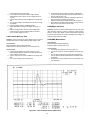
Load Transient Recovery Time
Definition: This is the time for the output voltage to return to within a
specified bend around its voltage following a step change in load.
Test Parameter:
Measured Variable: Output Voltage Transients
Expected Results: Less than 50 usec (at 10 mV from base line)
Test Procedure:
a. Connect the test equipment as shown in Figure A-2, but
replace the DVM with the oscilloscope. Operate the electronic
load in constant current mode.
b. Turn the unit's power on and turn CURRENT control fully clockwise.
c. Turn up output voltage to the full rated value.
d. Set the electronic load to transient operation mode between
one half of unit's full rated value and unit's full rated value at a 1
KHz rate with 50% duty cycle.
e. Set the oscilloscope for ac coupling, internal sync and lock on
either the positive or negative load transient.
f. Adjust the oscilloscope to display transients as in Figure A-3.
g. Check that the pulse width of the transients at 10 mV from the
base line is no more than 50 usec as shown.
PARD(Ripple and Noise)
Definition: Periodic and random deviation(PARD) in the unit's output
ripple and noise combine to produce a residual ac voltage superimposed on the dc output voltage. Constant voltage PARD is specified
as the root-mean-square(rms) or peak-to-peak(pp) output voltage in a
frequency range of 20 Hz to 20 MHz.
PARD(RMS) Measurement
Test Parameter:
Measured Variable: Output Voltage(rms)
Expected Results: Less than 200 uV rms
Test Procedure:
a. Connect the test equipment as shown in Figure A-4.
b. Turn the unit's power on and turn CURRENT control fully clockwise.
c. Turn up output voltage to the full rated value. Check that the
unit's CV indicator remains lighted. Reduce VOLTAGE control
if not lighted.
d. Check that the rms noise voltage at the true rms voltmeter is no
more than 200 uV.
Figure A-3. Load Transient Recovery Waveform
A-3
the load current is fed to the extremes of the wire leading to the resistor while the sampling terminals are located as close as possible to
the resistance portion itself. Generally, any current sampling resistor
should be of the low noise, low temperature coefficient type end
should be used at no more than 5% of its rated power so that its temperature rise will be minimized.
Load Effect(Load Regulation)
Definition: CC Load Effect is the change in dc output current when
load resistance changes from short circuit to full load or from full load
to short circuit.
Test Parameter:
Measured Variable: Output Current
Expected Results: Less than 0.01% plus 1 mA
Figure A-4. RMS Measurement Test Setup
PARD(Peak-to-Peak) Measurement
Test Parameter:
Measured Variable: Output voltage(peak-to-peak)
Expected Results: Less than 2 mV p-p
Test Procedure:
a. Connect the test equipment as shown in Figure A-5.
b. Turn the unit's power on and turn CURRENT control fully clockwise.
c. Turn up output voltage to the full rated value. Check that the
unit's CV Indicator remains lighted. Reduce VOLTAGE control
if not lighted.
d. Set the oscilloscope to AC mode and bandwidth to 20 MHz.
e. Check that the peak-to-peak noise is no more than 2 mV.
Test Procedure:
a. Connect the DVM across Rs in Figure A-2. Operate the electronic load in constant voltage mode and set its voltage to the
full rated value of power supply.
b. Turn the unit's power on and turn VOLTAGE control fully clock
wise.
c. Turn up output current to the full rated value. Check that the
AMPS display reads full rated values and CC indicator remains
lighted. Reduce CURRENT control if not lighted.
d. Record the voltage across Rs and convert it to current through
dividing by Rs.
e. Operate the electronic load in short(input short mode).
f. When the reading settles, record voltage across Rs again.
Check that the two recorded readings differ no more than
0.01% of output current plus 1 mA.
Source Effect(Line Regulation)
Definition: Source Effect is the change in dc output current when the
ac input voltage changes from the minimum to maximum val ue(± 10%
of nominal voltage).
Test Parameter:
Measured Variable: Output Current
Expected Results: Less than 0.01% plus 1 mA
Figure A-5. Peak-to-Peak Measurement Test Setup
Test Procedure:
a. Connect the DVM across Rs in Figure A-2. Operate the electronic load in constant voltage mode and set its voltage to the
full rated value of power supply.
b. Connect the unit to the ac power line through a variable autotransformer that set for low line voltage(104 Vac for 115 Vec).
c. Turn the unit's power on snd turn VOLTAGE control fully clock wise.
d. Turn up output current to the full rated value. Check that the
AMPS display reads full rated values and CC indicator remains
lighted. Reduce CURRENT control if not lighted.
e. Record output voltage across Rs and convert it to current through
dividing by Rs.
f. Adjust autotransformer to the high line voltage(127 Vac for 115 Vac).
g. When the reading settles, record the voltage across Rs again.
Check that the two recorded readings differ no more than 0.01%
of output current plus 1 mA.
PARD(Ripple and Noise)
Constant Current(CC) Tests
For output current measurements the current sampling resistor must
be treated as a four terminal device. In the manner of a meter shunt,
Definition: Periodic and random deviation(PARD) in the unit's output
ripple and noise combine to produce a residual ac current as well as
A-4
an ac voltage superimposed on the dc output. Constant Current
PARD is specified as the root-mean-square(rms) output current in e
frequency range of 20 Hz to 20 MHz with the unit in CC operation.
PARD(RMS) Measurement
CALIBRATION PROCEDURE
To calibrate ammeter and full scale current, connect test equipments
as shown in Figure A-7.
Test Parameter:
Measured Variable: Output Current(rms)
Expected Results: Less than 200 uA rms
Test Procedure:
a. Connect the test equipment as shown in Figure A-6.
b. Turn the unit's power on and turn the VOLTAGE control fully
clockwise.
c. Turn up output current to the full rated value. Check that the
CC indicator remains lighted. Reduce CURRENT control if not
lighted.
d. Record rms voltage across Rs and convert it to current through
dividing by Rs.
e. Check that the rms noise current is no more than 200 uA.
PARD(Peak-to-Peak) Measurement
Test Parameter:
Measured Variable: Output Current(peak-to-peak)
Expected Results: Less than 1 mA p-p
Figure A-7. Calibration in High Current Range
Test Procedure:
a. Connect the test equipment as shown in Figure A-6, but
replace the RMS voltmeter with oscilloscope.
b. Set the oscilloscope to AC mode and bandwidth to 20 MHz.
c. Turn the unit's power on and turn the VOLTAGE control fully
clockwise.
d. Turn up output current to the full rated value. Check that the
CC indicator remains lighted. Reduce CURRENT control if not
lighted.
e. Record peak-to-peak voltage across Rs and convert it to current through dividing by Rs. Check that the peak-to-peak noise
current is no more than 1 mA.
Calibration in High Current Range
a. Turn VOLTAGE and CURRENT control fully clockwise.
b. Set RANGE push button to high current range.
c. Turn on power supply and adjust R31 so that DVM indicates
exactly as follows (5% over rated current):
E3610A: 0.315 V
E3611A: 0.158 V
E3612A: 0.053 V
d. Adjust R3 on the display board so that the displayed value on
the front panel is equal to DVM value divided by Rs.
e. While depressing CC SET push button, adjust R20 so that the
displayed value on the front panel is equal to DVM value
divided by Rs.
Calibration in Low Current Range
a. Set RANGE push button to low current range.
b. Adjust R32 so that DVM indicates exactly as follows (5% over
rated current).
E3610A: 0.21 V E3611A: 0.089 V E3612A: 0.026 V
Calibration of VOLTS Meter
a. Disconnect the current shunt(Rs) and connect DVM across output of supply.
b. Set RANGE push button to low current range at no load.
c. Adjust VOLTAGE control till DVM indicates exactly as follows
(full rated voltage):
E3610A: 15 V
E3611A: 35 V
E3612A: 120 V
Figure A-6. RMS Measurement Test setup
d. Adjust R10 on the display board so that the value of the front
panel display is the same as the value of DVM.
A-5
#$"
'%
'%
'%
#
#
#
#
"
#
"
#
"
#$"
%
%
%
%
%%
"%%"
""
"
"
"
"
"
"
"
"
"
"
"
"
"
"
"
"
"
"
"
"
&
"
""
"
"
"
"
"
"
!
!!# !
"
"
!%!
!%
!## !## !
#&
#&
#&&
!&&
#!!
!# #!!
!# ## !!
#& #& #& #&
#&
#
##
!#%
!#%
!#%
!#%
!#%
!#%
!#%
!#%
!#%
# ! !#### #
# !
# ! #
#&
!!
#
!
#
# ! # !
&(
(
(
(
(
(
(
&
(
(
(
(
&(
(
&
(
&(
(
(
(
(
(
A-6
!
!
%
%
%
%
%
%%"
%
%
%
%
%
%
%
%
%
"%
%
%
%
%
%
%
'
'%
%
%%%
"%
""
""
"
""
"
"
""
"
"
"
"
"
"
"
"
"
"
""
"
"
""
"
""
"
"
"
"
"
"
""
"
"
"
"
""
""
"
"
"
"
"
"
"
"
"
"
(
(
&
(
#
(
#(
#(
#&(!
#&
(!
#&(!
#&
(&
#(&
#(&
#&(&
) #(&
#(&
#
&(&
#(&
#(&
) %
#(
#(
#(&
#&(&
#&"(&
#&(!
#(&
#"(&
#(&
#"&"(&
#(
#
&(&
#&(&
#(&
#(&
#&(&
) #&(&
#&"(&
#(
#(
#&(&
#&
(&
#&(&
#(&
#(&
#&(!
#&
(!
#(!
#
(&
#&(&
#(&
#&(&
#"(
#(
#
# #(&
!
&$
&
*&"
! " "
#!# !
#!!
!
# !&
!&
!# !
A-7
!
*
!
"!
"
!
!
!
%
)
%
)
%)
"
%
"
"
#&
#&&
"
"
"
""
"
"
# !#
!!#
#& #& # ! #
) ) "
&
#(!
#(!
#(!
!
!
!
!!
!!
!!
! !#%
! !#%
! !#%!
!
!
A-8
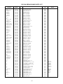
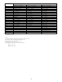
Model
Component
%
%
%
%
%"
%
'%
)
)
+
(
+
(
+
(
+(
+(
+
(
+(
+(
+(
&+(!
&+(&
+(&
&+(&
) +(
&+(&
+(&
&+(&
+(&
&+(&
&+(&
+(&
&+(!
+(!
+(
&
+(!
&+(&
+(&
&+(&
+(&
+(&
+(
&"+(&
"&"+(&
&+(&
&+(&
&+(&
&
+(&
+(&
&
+(!
+(!
"+(
+(
+
(
&+
(
+
(
+(
+(
&+
(
+(
&+(!
) +(&
+(&
+(&
+(&
+(
&+(!
"&"+(&
&+(&
) &"+(&
&+(&
+(!
+(!
+(&
+(&
&+(&
#!!
!
# ) ) ) ,!!
!#&./0123/45122647849/9:,71;</=1;/>.4?9@9:./1A40/647849/9:0123/:1A2/&
&22;/>@>:4;>1;/&
%+(%19=4.7>%392/>>4:./;?@>/>8/6@5@/=&
&2261816@:4;>1;/7@6;451;1=>%392/>>4:./;?@>/>8/6@5@/=&
&##>?@:6.>.4?9@>84>@:@49&
&#
!>/2/6:4;>?@:6.>.4?9@>[email protected];;/9:;19B/&
&42:1B/>A/:?//9
19=@924?63;;/9:;19B/1;/1>A/24?>&
+(
+(
+(
A-9
I
CERTIFICATION
Agilent Technologies certifies that this product met its published specifications at time of shipment from the factory. Agilent
further certifies that its calibration measurements are traceable to the United States National Institute of Standards and Technology (formerly National Bureau of Standards), to the extent allowed by that organization's calibration facility, and to the calibration facilities of other International Standards Organization members.
WARRANTY
This Agilent Technologies hardware product is warranted against defects in material and workmanship for a period of three
years from date of delivery. Agilent software and firmware products, which are designated by Agilent for use with a hardware
product and when properly installed on that hardware product, are warranted not to fail to execute their programming instructions due to defects in material and workmanship for a period of 90 days from date of delivery. During the warranty period,
either Agilent or Agilent Technologies will, at its option, either repair or replace products which prove to be defective. Agilent
does not warrant that operation the software, firmware, or hardware shall be uninterrupted or error free.
For warranty service, with the exception of warranty options, this product must be returned to a service facility designated by
Agilent. Return to Englewood Colorado Service Center for repair in United States(1-800-258-5165). Customer shall prepay
shipping charges by (and shall pay all duty and taxes) for products returned to Agilent for warranty service. Except for the
products returned to Customer from another country, Agilent shall pay for return of products to Customer.
Warranty services outside the country of initial purchase are included in Agilent's product price, only if Customer pays Agilent
international prices (defined as destination local currency price, or U.S. or Geneva Export price).
If Agilent is unable, within a reasonable time, to repair or replace any product to condition as warranted, the Customer shall
be entitled to a refund of the purchase price upon return of the product to Agilent.
The warranty period begins on the date of delivery or on the date of installation if installed by Agilent.
LIMITATION OF WARRANTY
The foregoing warranty shall not apply to defects resulting from improper or inadequate maintenance by the Customer, Customer-supplied software or interfacing, unauthorized modification or misuse, operation outside of the environmental specifications for the product, or improper site preparation and maintenance. TO THE EXTENT ALLOWED BY LOCAL LAW, NO
OTHER WARRANTY IS EXPRESSED OR IMPLIED. AND AGILENT SPECIFICALLY DISCLAIMS THE IMPLIED WARRANTIES OF MERCHANTABILITY AND FITNESS FOR A PARTICULAR PURPOSE.
For consumer transactions in Australia and New Zealand:
The warranty terms contained in this statement, except to the extent lawfully permitted, do not exclude, restrict or modify and
are in addition to the mandatory rights applicable to the sale of this product to you.
EXCLUSIVE REMEDIES
TO THE EXTENT ALLOWED BY LOCAL LAW, THE REMEDIES PROVIDED HEREIN ARE THE CUSTOMER'S SOLE AND
EXCLUSIVE REMEDIES. AGILENT SHALL NOT BE LIABLE FOR ANY DIRECT, INDIRECT, SPECIAL, INCIDENTAL, OR
CONSEQUENTIAL DAMAGES, WHETHER BASED ON CONTRACT, TORT, OR ANY OTHER LEGAL THEORY.
ASSISTANCE
The above statements apply only to the standard product warranty. Warranty options, extended support contacts, product
maintenance agreements and customer assistance agreements are also available. Contact your nearest Agilent Technologies Sales and Service office for further information on Agilent's full line of Support Programs.
DECLARATION OF CONFORMITY
According to ISO/IEC Guide 22 and CEN/CENELEC EN 45014
Manufacturer’s Name and Addresss
Responsible Party
Agilent Technologies, Inc.
550 Clark Drive, Suite 101
Budd Lake, New Jersey 07828
USA
Alternate Manufacturing Site
Agilent Technologies (Malaysia) Sdn. Bhd
Malaysia Manufacturing
Bayan Lepas Free Industrial Zone, PH III
11900 Penang,
Malaysia
Declares under sole responsibility that the product as originally delivered
Product Name:
a) Single Output dc Power Supply (dual range)
b) Single Output dc Power Supply (single range)
c) Single Output System Power Supply
d) Multiple Output dc Power Supply
e) Multiple Output System dc Power Supply
Model Number:
a) E3610A, E3611A, E3612A
b) E3614A, E3615A, E3616A, E3617A
c) E3632A
d) E3620A, E3630A
e) E3631A
Product Options:
This declaration covers all options of the above product(s).
Complies with the essential requirements of the Low Voltage Directive 73/23/EEC and the EMC
Directive 89/336/EEC (including 93/68/EEC) and carries the CE Marking accordingly .
EMC Information
ISM Group 1 Class A Emissions
As detailed in
Electromagnetic Compatibility (EMC), Certificate of Conformance Number
CC/TCF/00/102 based on Technical Construction File (TCF) ANJ12, dated
Dec.20, 2000.
Assessed by:
Celestica Ltd, Appointed Competent Body
Westfields House, West Avenue
Kidsgrove, Stoke-on-Trent
Straffordshire, ST7 1TL
United Kingdom
Safety Information
and Conforms to the following safety standards.
IEC 61010-1:2001 / EN 61010-1:2001
CSA C22.2 No. 1010.1:1992
This DoC applies to above-listed products placed on the EU market after:
January 1, 2004
Date
Bill Darcy/ Regulations Manager
For further information, please contact your local Agilent Technologies sales office, agent or distributor, or
Agilent Technologies Deutschland GmbH, Herrenberger Straβe 130, D71034 Böblingen, Germany
Revision: B.00.00
Issue Date: Created on 11/24/2003 3:10
PM
Document No. KIO_10-32.11.24doc.doc