1
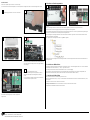
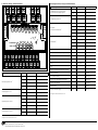
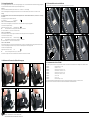
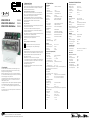
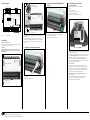
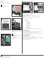
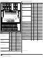
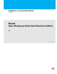
110910 110912 110913 9467/899340 EWIO-9180-M EWIO-9180-M-BACnet EWIO-9180-M-Modbus 2. Wichtige Hinweise 3. Technische Daten Konformitätserklärung Das Gerät wurde nach den geltenden Normen geprüft. Die Konformität wurde nachgewiesen. Die Konformitätserklärung ist beim Hersteller METZ CONNECT GmbH abrufbar. Hinweise zur Gerätebeschreibung Die Beschreibung enthält Hinweise zum Einsatz und zur Montage des Geräts. Sollten Fragen auftreten, die nicht mit Hilfe dieser Anleitung geklärt werden können, sind weitere Informationen beim Lieferanten oder Hersteller einzuholen. Die angegebenen Vorschriften/Richtlinien zur Installation und Montage gelten für die Bundesrepublik Deutschland. Beim Einsatz des Geräts im Ausland sind die nationalen Vorschriften in Eigenverantwortung des Anlagenbauers oder des Betreibers einzuhalten. Sicherheitshinweise Für die Montage und den Einsatz des Geräts sind die jeweils gültigen Arbeitsschutz-, Unfallverhütungs- und VDE-Vorschriften einzuhalten. Facharbeiter oder Installateure werden darauf hingewiesen, dass sie sich vor der Installation oder Wartung der Geräte vorschriftsmäßig entladen müssen. Montage- und Installationsarbeiten an den Geräten dürfen grundsätzlich nur durch qualifiziertes Fachpersonal durchgeführt werden, siehe Abschnitt “qualifiziertes Fachpersonal”. Jede Person, die das Gerät einsetzt, muss die Beschreibungen dieser Anleitung gelesen und verstanden haben. Warnung vor gefährlicher elektrischer Spannung Schnittstellen Gefahr 1. Beschreibung Der EWIO-9180-M (Ethernet Web I/O-9180-Metering) ist ein leistungsstarker Datenlogger u. a. für Aufgaben im Energiemanagement und Energiecontrolling. Über die integrierten I/Os der M-Bus- und RS485-(stty3) Systemschnittstelle lassen sich Zählerdaten, Temperaturen etc. erfassen sowie Schalt- und Stellsignale erzeugen. Eine integrierte Datenbank stellt die Daten für übergeordnete Energiemanagementsysteme über LAN bereit. Optional kann eine Verbindung zur Managementebene über WLANoder UMTS-Adapter erfolgen. Ein integrierter Webserver ermöglicht plattformunabhängig über einen Webbrowser die Konfiguration und Parametrierung des EWIO-9180-M. C/C++, Linux Shell und JAVA programmierte Applikationen sind direkt lauffähig. Durch optional anschließbare Erweiterungsmodule lässt sich die I/O-Anzahl erhöhen. bedeutet, dass bei Nichtbeachtung Lebensgefahr besteht, schwere Körperverletzungen oder erhebliche Sachs chäden auftreten können. Qualifiziertes Fachpersonal Qualifiziertes Fachpersonal im Sinne dieser Anleitung sind Personen, die mit den beschriebenen Geräten vertraut sind und über eine ihrer Tätigkeit entsprechenden Qualifikation verfügen. Hierzu gehören zum Beispiel: ••Berechtigung zum Anschluss des Geräts gemäß den VDEBestimmungen und den örtlichen EVU-Vorschriften sowie Berechtigung zum Ein-, Aus- und Freischalten des Geräts unter Berücksichtigung der innerbetrieblichen Vorschriften; ••Kenntnis der Unfallverhütungsvorschriften; ••Kenntnisse über den Einsatz und Gebrauch des Geräts innerhalb des Anlagensystems usw. METZ CONNECT GmbH | Im Tal 2 | 78176 Blumberg | Deutschland Telefon +49 7702 533-0 | Fax +49 7702 533-433 Weitere Dokumentation siehe www.metz-connect.com Netzwerk: Protokolle: EWIO-9180 EWIO-9180-BACnet EWIO-9180-Modbus Fortsetzung Technische Daten Ethernet 10/100BaseT TCP/IP TCP/IP & BACnet/IP TCP/IP & Modbus TCP Anschluss:RJ45-Buchse Debugschnittstelle: serielle Schnittstelle 0 bis 3,3 V DC Systembus: Erweiterungsmodule (I/Os) Modbus RTU Modbus I/Os, MR-Serie USB WLAN-Adapter Chipsatz Ralink 2870 und 3070 UMTS-Adapter Chipsatz ID 0681:0047 Speicherkartenslot microSD (2 GB integriert) Controller Einheit Prozessor ARM9 180 MHz interner Speicher RAM 128 MB / Flash 64 MB externer Speicher bis 8 GB microSD (2GB installiert) Betriebssystem embedded Standard Linux, Kernel Version 2.6.38 MC RealTimeClock Ganggenauigkeit 1 s/Tag; Spannungsausfall überbrückung 24 Std. Versorgung Betriebsspannung UB: 24 V DC ±10 % Stromaufnahme: 640 mA Verlustleistung: 16 W Netzgerät:optional Ein- und Ausgänge (I/Os) Digitale Eingänge Optokoppler 4x optisch getrennt Eingangsspannung max. UB Higherkennung >7 V AC/DC Zählfrequenz 2 kHz S0-Schnittstelle nach DIN EN 62053-31 Klasse B Eingänge 4 Zählfrequenz max. 17 Hz Hinweis: Konfiguration der S0-Stromschnittstelle siehe EWIO-M Benutzerhandbuch - Kapitel „Gerät/Konfiguration I/O“ Digitale Ausgänge Relaisausgang 4x Wechsler 250 V / 5 A Transistorausgang Spannungsquelle mit Strombegrenzung 3x PNP 24 V DC / 20 mA nicht schaltbar 1x PNP 15 V DC / 30 mA nicht schaltbar Analoge Eingänge 14 Bit 2x konfigurierbar als: entweder Widerstandsbereich 40 Ohm bis 4 MOhm Auflösung 0,01 Ohm Fehler ca. ±0,2 Ohm Der Leitungslängenabgleich erfolgt über den dem Temperatur eingang zugeordneten Taster E1/E2 (siehe Punkt 13). oder Spannungseingang 0 bis 10 V DC Auflösung 10 mV (0 bis 100 %) Fehler ca. ±20 mV 2x Stromeingänge 2x 0 bis 20 mA DC Auflösung 0,01 mA Fehler < 0,1 mA Analoge Ausgänge 14 Bit 2x Spannungsausgänge Ausgangsstrom Auflösung Fehler 2x Stromausgänge Auflösung Fehler 2x 0 bis 10 V DC 5 mA (10 V DC) 10 mV 10 mV 2x 0 bis 20 mA DC < 0,01 mA < 0,1 mA Gehäuse Abmessungen (BxHxT) Gehäuse Gewicht Einbaulage Montage Anreihung Schutzart (IEC 60529) Gehäuse Klemmen 125 x 90 x 60 mm 45 mm Kappenmaß / 7 TE 400 g beliebig, horizontal empfohlen Tragschiene TH35 nach IEC 60715 ohne Abstand möglich IP20 IP20 Material Gehäuseoberteil Gehäuse Farbe Gehäuseoberteil Gehäuseunterteil Gehäusedeckel PC Polycarbonat PA Polyamid transluzent schwarz lichtgrau Anschlussklemmen Geräteanschluss Ein-/Ausgänge Aderndurchmesser 0,33 bis 2,5 mm² / AWG 22 - 12 0,3 bis max. 2,7 mm Anzeige Betriebsanzeigen LED Active/Boot Power on - ok grün Bootvorgang Fehler rot Linkgrün 10/100 MBit grün Collisionrot Zustandsanzeigen LED Schaltzustände gelb Leitungslängenabgleich gelb Einmann-Inbetriebnahme gelb M- M+ B’+ A’- 42 44 41 M-Bus 8. Erreichbarkeit des EWIO-M 8.1 über Webbrowser Der EWIO-M hat im Auslieferungszustand folgende IP-Voreinstellungen: ••DHCP ••Falls kein DHCP vorhanden, Einstellung auf IP-Adresse 192.168.0.111 ••Gateway-Adresse 192.168.0.1 ••Einstellung des Webbrowsers siehe EWIO-M Handbuch Spannungsversorgung 24 V DC über Brückenstecker 24 V GND B+ A- I2 I1 E2 E1 C2 C1 O2 A GND = 0 V = - (gleiches Potential) 5. Montage Anlage spannungsfrei schalten Gerät auf Tragschiene (TH35 nach IEC 60715, Einbau in Elektroverteiler / Schalttafel) setzen. Installation Die Elektroinstallation und der Geräteanschluss dürfen nur durch qualifiziertes Fachpersonal unter Beachtung der VDE-Bestimmungen und örtlicher Vorschriften vorgenommen werden. Anschluss mit separatem Netzgerät NG4 Gefahr! L1/N = 230 V AC/DC Nach Einschalten der Spannungsversorgung beginnt der Bootvorgang des EWIO-M. Während des Bootvorgangs leuchtet die LED „Boot“ rot. Nach ca. 50 Sekunden ist der Bootvorgang abgeschlossen und die LED „Boot“ wechselt von rot nach grün. Die LED „Boot“ befindet sich rechts neben dem Deckel. 6. Anschluss an das Ethernet-Netzwerk 1 Direktanschluss 24 V/0 V = 24 V DC 7. Anschluss an UMTS-/WLAN-Adapter über USB USB 4 Analogeingänge 4 Analog inputs 2 x 0..10 V 40 Ohm .. 4 MOhm 2 x 0 - 20 mA 4 Analogausgänge 4 Analog outputs 2 x 0..10 V DC/5 mA 2 x 0(4)..20 mA Modbus RTU 15 V DC/30 mA 24 V DC/20 mA DC Versorgung Supply Erweiterungen Extensions D D4 D3 D2 24 V DC/20 mA 24 V DC/20 mA D1 4 Digitaleingänge 4 Digital inputs 8+ 8- S04 4- 4 S0-Eingänge 4 S0 inputs DC-Versorgung DC Supply S01 1- 24 V 128MB RAM O1 64MB Flash Ethernet GND 32 34 31 RealTime Clock < 8GB Micro SD 2 5A 22 24 21 5A µP ARM9 DC - Versorgung DC - Supply Erweiterungen Extensions 5+ 5- 24 V GND B+ A- Fortsetzung Montage 5A 5A 12 14 11 4. Prinzipbild Den EWIO-M mit einem handelsüblichen RJ45-Patchkabel mit dem Ethernet-Netzwerk verbinden. Konfiguration siehe Benutzerhandbuch auf CD. METZ CONNECT GmbH | Im Tal 2 | 78176 Blumberg | Deutschland Telefon +49 7702 533-0 | Fax +49 7702 533-433 Weitere Dokumentation siehe www.metz-connect.com Den EWIO-M über die USB-Schnittstelle mit dem UMTS-/ WLAN-Adapter (optional erhältlich) verbinden. Hierzu die Spezifikation unter 3. Technische Daten/Schnittstellen/ USB beachten! Konfiguration siehe Benutzerhandbuch auf CD. MAC: 00:50:c2:3f:48:74 Um auf die Startseite des EWIO-M zu gelangen, geben Sie in der Browser-Adresszeile den Hostnamen oder die IP-Adresse ein. Ist in Ihrem Netzwerk DHCP vorhanden, setzt sich der Hostname aus “ewio-” und den letzten 3Byte der MAC-Adresse zusammen. Die MAC-Adresse befindet sich auf dem Typenschild, das sich seitlich auf dem Gerät befindet (siehe Bild oben). Beispiel: EWIO-9180-M mit MAC-Adresse MAC: 00:50:c2:3f:48:74 entspricht dem Hostnamen ewio-3f4874, den Sie in folgender Form in die Adresszeile des Browsers eingeben: http://ewio-3f4874 Wird kein DHCP-Server gefunden, wird die IP-Adresse 192.168.0.111 eingetragen. Befindet sich Ihr Netz im gleichen IP-Adressbeich, geben Sie in die Adresszeile des Browsers die IP-Adresse in folgender Form ein: http://192.168.0.111 Andernfalls müssen Sie mittels route add diese Adresse eintragen. Dazu unter Windows eine Cmd-Box öffnen und folgendes Kommando eingeben: route ADD 192.168.0.111 netmask 255.255.255.255 xxx.xxx (IP-Adresse des PCs). Weitere Informationen zur Einstellung des EWIO-9180-M, und zu den Browseranforderungen entnehmen Sie bitte dem Dokument “Web-Interface Benutzerhandbuch” auf der beiliegenden CD. 9. Anreihen von Erweiterungsmodulen 8.2 über Konsole Hierfür ist das optionale Adapterset Artikel-Nr. 110920 notwendig. Um über die Konsole auf den EWIO-M zuzugreifen, muss das Adapterset wie nachfolgend beschrieben an den EWIO-M angeschlossen werden. 1 Elektronikbaugruppe entfernen wie in Punkt 14 beschrieben 2 2 Hinweis! Max. 6 Erweiterungsmodule der Serie EW-xxx können an den EWIO-M angereiht und per Brückenstecker angeschlossen werden. Der Brückenstecker verbindet Versorgungsspannung und Bus an die angereihten Erweiterungsmodule. Jedes am EWIO-M angeschlossene Erweiterungsmodul muss auf eine eigene Adresse im Bereich von 0 bis 5 eingestellt sein. Bei doppelter Vergabe einer Adresse ist die Funktionsweise der Erweiterungsmodule nicht gewährleistet. Die Einstellungen der Erweiterungsmodule können über das Web-Interface des EWIO-M vorgenommen werden. Alle aktiven IO-Module sind im Verzeichnis Konfiguration / IO aufgelistet. Die angeschlossenen Erweiterungsmodule werden als “IO_extern” aufgeführt. Gehäusedeckel durch seitliches eindrücken lösen... 3 1 4 Stiftleiste Typenschild ... und nach oben abnehmen. 5 schwarz braun rot orange gelb grün Adapterplatine auf die zugehörigen Pins stecken. Dabei ist zu beachten, dass das Elektronikmodul mit dem Typenschild nach rechts zeigt und die Adapterplatine mit der 6-poligen Stiftleiste nach links zeigt. 6 Anschluss des Adapter-Kabels an den PC. Bevor die USB-Verbindung mit dem PC hergestellt wird, muss der USB-Treiber (siehe Adapterset) heruntergeladen und installiert werden. Erst nach erfolgreicher Installation des USB-Treibers den USB-Stecker mit dem USB-Port des Computers verbinden. Flachstecker des Adapter-Kabels auf die Stiftleiste aufstecken. Dabei auf die Farbreihenfolge achten, wie auf der Adapterplatine aufgedruckt ist! METZ CONNECT GmbH | Im Tal 2 | 78176 Blumberg | Deutschland Telefon +49 7702 533-0 | Fax +49 7702 533-433 Weitere Dokumentation siehe www.metz-connect.com Weitere Informationen zur Konfiguration und Einstellung des EWIO-M und der Erweiterungsmodule entnehmen Sie bitte der Dokumentation auf der beiligenden CD. 10. Anschluss von Modbus-Slaves Das EWIO-M verfügt über eine RS485-Schnittstelle (stty3), deren Baud-Rate bis max. 115000 Baud eingestellt werden kann. An dieser Schnittstelle können Modbus-Slaves über die Klemmen „A‘-“ und „B‘+“ angeschlossen werden. Der zulässige Adressbereich für weitere externe Modbus-Slaves ist auf 1 bis max. 99 festgelegt. Die Initiierung der Kommunikation erfolgt immer durch einen Modbus-Master (Softwareapplikation). Anwender habe die Möglichkeit, einen Modbus-Master auf das EWIO-M zu portieren (siehe Dokumentation auf CD: EWIO-M Treiber Modbus-Interface) 11. Anschluss von M-Bus-Geräten Max. 80 M-Bus-Lasten können an den EWIO-M angeschlossen werden. Hierzu verbinden Sie die Klemmen „M-“ und „M+“ mit den Busklemmen des M-Bus-Geräts. Bei Kurzschluss auf dem M-Bus blinkt die LED „Active/ Boot“ grün/rot. Im Webbrowser wird der Kurzschluss automatisch dokumentiert. Achtung! Polarität beachten! Die zwei Anschlussblöcke (M- und M+) sind intern miteinander verbunden. Konfiguration siehe Benutzerhandbuch der Modbus RTU Module. 12. Anschlüsse, Anzeige- und Bedienelemente Fortsetzung Anschlüsse, Anzeige- und Bedienelemente Beschreibung Taster Analogeingang 0 bis 10 V/40 bis 4 MOhm bei Widerstand Leitungslängenabgleich 1 E1 E1/- E2 E2/- I2/- S04 Lin S01 S02 S03 S04 O1 O2 C1 C2 E1 E2 S0-Eingang mit Einmann-Inbetriebnahme 1 S01 S01/1- (1- = ON) S01 | ON (gelb) S02 S02/2- (2- = ON) S02 | ON (gelb) S03 S03/3- (3- = ON) S03 | ON (gelb) S04 S04/4- (4- = ON) S04 | ON (gelb) 5+/5- DI5 6+/6- DI6 7+/7- DI/ 8+/8- DI8 se t S03 Re S02 k 10 /10 0 Co llis ion S01 A Bo ctive ot K1 K2 K3 K4 +24V GND B+ A- Digitaleingang 1 DI5 DI6 DI7 DI8 Betriebsspannung 1 24 V/ 0 V Brückenstecker für Betriebsspannung 1 24 V/ GND RS485 (stty3) 1 Brückenstecker für Erweiterungsmodule M-Bus Beschreibung Relaisausgang Wechsler 5 A 1 Analogausgang 0 bis 10 V 1 Taster 1) Konfiguration B+/A- | B+/A- 1 M+/M- | M+/M- USB 1 USB Ethernet 10/100 MBit Kommunikationsschnittstelle 1 RJ45 Link (grün) K1 | ON (gelb) 10/100-MBit-Verbindung 100 MBit (grün) 21-22-24 K2 | ON (gelb) Kollision auf der Kommunikationsschnittstelle Collision (rot) 31-32-34 K3 | ON (gelb) EWIO-M ist betriebsbereit Active (grün) 41-42-44 K4 | ON (gelb) EWIO-M bootet Boot (rot) O1/- O1 | ON (gelb) EWIO-M neuer Bootvorgang O2/- O2 | ON (gelb) LED-Anzeige 11-12-14 D2/D3/D4/- Analogausgang 0 bis 20 mA 1 B‘+/A‘- | B‘/A‘ 1 Ethernet-Verbindung Kontakte D1/Digitalausgang 24 V / 20 mA 1 LED-Anzeige I1/- Analogeingang 0 bis 20 mA 1 +24V GND B+ A- Kontakte C1/- C1 | ON (gelb) C2/- C2 | ON (gelb) siehe Benutzerhandbuch auf CD. METZ CONNECT GmbH | Im Tal 2 | 78176 Blumberg | Deutschland Telefon +49 7702 533-0 | Fax +49 7702 533-433 Weitere Dokumentation siehe www.metz-connect.com 1) Konfiguration siehe Benutzerhandbuch auf CD Reset Reset (rot) 13. Leitungslängenabgleich 15. Einsetzen/Entfernen der microSD Karte Der Leitungslängenabgleich ist erforderlich, wenn die analogen Eingänge E1 bzw. E2 über die Web-Oberfläche als Widerstandseingang konfiguriert sind (siehe hierzu EWIO-M Benutzerhandbuch Kapitel „Gerät/Konfiguration I/O“). Vor dem Einsetzen der microSD Karte muss die Elektronikbaugruppe entfernt (siehe 14) werden! Vorgehen: Es wird ein handelsüblicher Widerstand (RX) im Bereich von ca. 100 Ohm bis ca. 1 kOhm benötigt. Die höchste Genauigkeit für die Leitungslängen-Kompensation kann man mit einem Widerstand (RX) im Bereich von 100 Ohm erreichen. Wichtig: Die nachfolgenden drei Schritte müssen hintereinander durchgeführt werden. Wird der Ablauf unterbrochen, muss mit Schritt 1 neu begonnen werden! Versorgungsspannung an das EWIO-M anklemmen. LED „Active Boot“ leuchtet grün Schritt 1 - erster Tastendruck [Taster E1 oder E2] Hiermit wird der Kanal ausgewählt, der kompensiert werden soll und der Kompensierungsvorgang eingeleitet. Am Gerät erscheint folgende Anzeige: Zugeordnete Kanal-LED [E1 oder E2] blinkt langsam grün á Referenz-Widerstand ohne Leitung direkt an Klemme [E1 / -] anklemmen. Nach dem Anschließen ca. 1 s warten. Dann weiter mit Schritt 2. Schritt 2 - zweiter Tastendruck Mit dem zweiten Tastendruck wird der angeschlossene Widerstand (RX) sofort gemessen und zwischengespeichert. Am Gerät erscheint folgende Anzeige: Zugeordnete Kanal-LED [E1 oder E2] blinkt schneller grün á Referenz-Widerstand mit Leitung direkt an Klemme [E1 / -] anklemmen. Nach dem Anschließen ca. 1 s warten. Dann weiter mit Schritt 3. Schritt 3 - dritter Tastendruck Mit dem dritten Tastendruck wird der angeschlossene Widerstand (RX+RL) gemessen. Anschließend wird der Leitungswiderstand (RL) berechnet, welcher der Leitungslängen-Kompensation entspricht. Dieser wird nullspannungssicher im EWIO-M gespeichert. Am Gerät erscheint folgende Anzeige: Zugeordnete Kanal-LED [E1 oder E2] AUS á Sensor mit Leitung direkt an Klemme [E1 / -] anklemmen. Die Prozedur ist für jeden Kanal einzeln durchzuführen. Die Installation der Hardware ist nun beendet. 1 2 3 4 5 6 kte ! nta en Ko unt B h c 8G na x. ma 14. Entfernen und Einsetzen der Elektronikbaugruppe 1 2 16. Dokumentation auf der CD-ROM Die vollständige Dokumentation zur Nutzung des EWIO-9180-M ist in den elektronischen Handbüchern auf der beiliegenden CD-ROM beschrieben 3 ••EWIO-M Benutzerhandbuch vx.xx.PDF ••EWIO-M Quickstart vx.xx.PDF ••EWIO-M Treiber M-Bus - InterFace vx.xx.PDF ••EWIO-M Treiber Modbus - InterFace vx.xx.PDF ••EWIO-M Treiber M-Bus - InterFace vx.xx.PDF ••EWIO-M Treiber System - InterFace vx.xx.PDF ••EWIO-M Linux vx.xx.PDF ••EWIO-M ppp vx.xx.PDF ••EWIO-M WLAN-Anbindung vx.xx.PDF Des weiteren beinhaltet die CD-ROM Beispiele zum Nutzen und Erzeugen des Bootmanagers (Uboot), des Linux Kernels, des Root File Systems und der Anwender-Daten-Partition und Dateien zum Wiederherstellen des Auslieferzustandes. Vor dem Einsetzen der Elektronikbaugruppe muss der Auswurfhebel nach hinten gelegt werden! 4 5 6 Press Ë Ê klick Auswurfhebel METZ CONNECT GmbH | Im Tal 2 | 78176 Blumberg | Deutschland Telefon +49 7702 533-0 | Fax +49 7702 533-433 Weitere Dokumentation siehe www.metz-connect.com 110910 110912 110913 9467/899340 EWIO-9180-M EWIO-9180-M-BACnet EWIO-9180-M-Modbus 1. Description 2. Important Notes 3. Technical Data Declaration of Conformity The device was tested according to the applicable standards. Conformity was proofed. The declaration of conformity is available at the manufacturer METZ CONNECT GmbH. Notes Regarding Device Description These instructions include indications for use and mounting of the device. In case of questions that cannot be answered with these instructions please consult supplier or manufacturer. The indicated installation directions or rules are applicable to the Federal Republic of Germany. If the device is used in other countries it applies to the equipment installer or the user to meet the national directions. Safety Instructions Keep the applicable directions for industrial safety and prevention of accidents as well as the VDE rules. Technicians and/or installers are informed that they have to electrically discharge themselves as prescribed before installation or maintenance of the devices. Only qualified personnel shall do mounting and installation work with the devices, see section “qualified personnel”. The information of these instructions have to be read and understood by every person using this device. Symbols Warning of dangerous electrical voltage Danger means that non-observance may cause risk of life, grievous bodily harm or heavy material damage. Interfaces Qualified Personnel Qualified personnel in the sense of these instructions are persons who are well versed in the use and installation of such devices and whose professional qualification meets the requirements of their work. This includes for example: ••Qualification to connect the device according to the VDE specifications and the local regulations and a qualification to put this device into operation, to power it down or to activate it by respecting the internal directions. ••Knowledge of safety rules. ••Knowledge about application and use of the device within the equipment system etc. The EWIO-9180-M (Ethernet-Web-I/O-9180-Metering) is a high performance data logger; among others for functions in energy management and energy controlling. Meter data, temperatures etc. can be recorded via the intergrated I/Os, the M-Bus and RS485 (stty3) system interfaces, and switching and actuating signals can be generated. An integrated data base supplies the data for higher level energy management systems via LAN. Also, a connection via WLAN or UMTS adapter is possible. An integrated web server allows a platform independent configuration and parameterization of the EWIO-9180-M via internet browser. C/C++, JAVA and Linux shell programmed applications are directly executable. The number of I/Os can be increased by extension modules that are connected to the device. METZ CONNECT GmbH | Im Tal 2 | 78176 Blumberg | Germany Phone +49 7702 533-0 | Fax +49 7702 533-433 Additional documentation see www.metz-connect.com Network: Protocols: EWIO-9180 EWIO-9180-BACnet EWIO-9180-Modbus Connection Debug interface System bus Modbus RTU USB WLAN adapter UMTS adapter Memory card slot Controller Unit Processor Internal memory External memory Operating system RealTimeClock clock accuracy power failure bridging Continuation Technical Data Ethernet 10/100BaseT TCP/IP TCP/IP & BACnet/IP TCP/IP & Modbus TCP RJ45 jack serial interface 0 - 3.3 V DC extension modules (I/Os) Modbus I/Os, MR-Series Chipset Ralink 2870 and 3070 Chipset ID 0681:0047 microSD (2 GB integrated) ARM9 180 MHz RAM 128 MB / Flash 64 MB 8 GB microSD (2 GB installed) embedded Standard Linux, Kernel Version 2.6.38 MC 1 s/day 24 h Supply Operating voltage UB Current consumption Power loss Power supply 24 V DC ±10 % 640 mA 16 W optional Inputs and outputs (I/Os) Digital inputs Optocoupler 4x optically separated Input voltage max. UB High-recognition >7 V AC/DC Counting frequency 2 kHz S0 current interface per DIN EN 62053-31 Class B Inputs 4 Counting frequency max. 17 Hz Note: See EWIO-M user manual - chapter „device/configuration I/O“ to configurate the S0 current interface. Digital outputs Relay outputs 4x changeover contacts 250 V / 5 A Transistor output (voltage source with current limitation) 3x PNP 24 V DC / 20 mA not switchable 1x PNP 15 V DC / 30 mA not switchable Analog inputs 14 Bit 2x configurable Resistance range 40 Ohms to 4 MOhms Resolution 0.2 K Error about ±0.2 °C Cable length compensation is made by the key E1/E2 assigned to the temperature input. Voltage input 0 to 10 V DC Resolution 10 mV (0 to 100 %) Error about ±10 mV Current input 2x 0 to 20 mA DC Resolution 0.05 mA Error < 0.1 mA Analog outputs 14 Bit Voltage output Output current Resolution Current output Resolution Error 0 to 10 V DC 5 mA (10 V DC) 10 mV 2x 0 to 20 mA DC 0.05 mA < 0.1 mA Housing Dimensions (WxHxD) 125 x 90 x 60 mm Housing 45 mm cover size / 7 HP Weight 400 g Mounting position any, horizontally recommended Mounting rail TH35 as per IEC 60715 Side-by-side mounting possible without distance Type of protection (IEC 60529) Housing IP20 Terminal blocks IP20 Material Upper part of housing Housing Color Upper housing part Lower housing part Housing cover PC polycarbonate PA polyamide translucent black light gray Terminal blocks Device connection Inputs/outputs 0.33 to 2.5 mm² / AWG 22 to 12 Wire diameter 0.3 to max. 2.7 mm Indication Operation indicator LED Power on Boot sequence/error Ethernet Link 10/100 MBit Status indicator LED Switching status Cable length adjustment One-man operation green red green green yellow yellow yellow M- M+ B’+ A’- 42 44 41 32 34 31 7.Connection to the UMTS/WLAN adapter by USB M-Bus 8.1 Via web browser The EWIO-M has the following IP factory settings: ••DHCP ••If no DHCP exists, setting to IP address 192.168.0.111 ••Gateway address 192.168.0.1 ••Web browser setting see EWIO-M manual 24 V GND B+ A- USB 4 Analogeingänge 4 Analog inputs 2 x 0..10 V 40 Ohm .. 4 MOhm 2 x 0 - 20 mA 4 Analogausgänge 4 Analog outputs 2 x 0..10 V DC/5 mA 2 x 0(4)..20 mA Modbus RTU I1 E2 E1 C2 C1 Connection with separate power supply NG4 Danger! L1/N = 230 V AC/DC I2 15 V DC/30 mA 8. Availability by web interface A O2 O1 24 V DC/20 mA DC Versorgung Supply Erweiterungen Extensions D D4 D3 D2 24 V DC/20 mA 24 V DC/20 mA D1 4 Digitaleingänge 4 Digital inputs 128MB RAM 8+ 8- S04 4- 4 S0-Eingänge 4 S0 inputs S01 1- 24 V GND DC-Versorgung DC Supply < 8GB Micro SD Voltage supply 24 V DC by jumper plug 5A 22 24 21 5A RealTime Clock 64MB Flash Ethernet 2 µP ARM9 DC - Versorgung DC - Supply Erweiterungen Extensions 5+ 5- 24 V GND B+ A- 5A 5A 12 14 11 4. Wiring diagram GND = 0 V = - (same potential) 5. Mounting Power down the equipment. Mount the device on standard rail (TH35 per IEC 60715 in junction boxes and/or on distribution panels). Installation Electric installation and device termination shall be done by qualified persons only, by respecting the VDE specifications and local regulations. When the power supply is switched-on the boot sequence of the EWIO-M starts. The LED „Boot“ is lighting red during the boot sequence. The boot sequence is finished after approximately 30 seconds and the LED „Boot“ changes from red to green. The LED „Boot“ is right next to the cover. 6. Connection to the Ethernet network 1 Connect the EWIO-M with a standard RJ45 patch cable to the Ethernet network. Configuration see User Manual on CD. Direct connection 24 V/0 V = 24 V DC METZ CONNECT GmbH | Im Tal 2 | 78176 Blumberg | Germany Phone +49 7702 533-0 | Fax +49 7702 533-433 Additional documentation see www.metz-connect.com Connect the EWIO-M via the USB interface to the UMTS/ WLAN adapter (optional available). See specifications item 3. Technical Data/Interfaces/USB! Configuration see User Manual on CD. MAC: 00:50:c2:3f:48:74 00:50:c2:3f:48:74 MAC: Enter the host name or the IP address in the browser address line to get to the EWIO-M home page. If your network has DHCP the host name is composed of “ewio-” and the last 3Byte of the MAC address. The MAC address is on the identification plate on the side of the device (see photo above). Example: EWIO-M with MAC address MAC: 00:50:c2:3f:48:74 makes the host name ewio-3f4874, that you enter in the address line of the browser in the following way: http://ewio-3f4874 If no DHCP server is found enter the IP address 192.168.0.111. If your network is in the same IP address range enter the IP address in the address line of the browser as follows: http://192.168.0.111 Otherwise you have to enter this address by route add. Open a cmd box in Windows and enter the following command: route ADD 192.168.0.111 netmask 255.255.255.255 xxx.xxx (IP-Addresse of the PC). Please consult the file „Web Interface User manual“ on the CD attached for any further information as to the settings of EWIO-M and the browser requirements. 9. Side-by-side mounting of extension modules 8.2 Via console The optionally available adapter set P/N 110920 is necessary for this. To access to the EWIO-M via console connect the adapter set to the EWIO-M as described below. 1 Remove the electronic unit as described in item 14. 1 2 Press on the sides of the housing cover to release it ... 3 4 Pin header ... and lift it upwards to take it off. schwarz braun rot orange gelb grün Connection of the adapter cable to the PC. First download and install the USB driver (see adapter set) before you make the USB connection with the PC. Connect USB plug with USB port of the PC only when the USB driver has been successfully installed. Plug the flat plug of the adapter cable on the pin header. Respect the color sequence as it is printed on the adapter board! METZ CONNECT GmbH | Im Tal 2 | 78176 Blumberg | Germany Phone +49 7702 533-0 | Fax +49 7702 533-433 Additional documentation see www.metz-connect.com Note! A maximum of 6 extension modules series EW-xxx can be mounted side-by-side to the EWIO-M and be connected by jumper plug. The jumper plug connects supply voltage and bus to the aligned extension modules. Each extension module connected to the EWIO-M has to be set to an own address between 0 to 5. If one address is assigned twice the functioning of the extension modules is not assured. Settings of the extension modules can be done by the web interface of the EWIO-M. All active I/O modules are listed in the folder Configuration / IO. The connected extension modules are specified as “IO_extern”. Identification plate Plug the adapter board on the respective pins. The electronic unit with the identification plate has to show to the right and the adapter board with the six pole pin header has to show to the left side. 6 5 2 For more information about configuration and setting of the EWIO-M and the extension modules see the documentation on the enclosed CD. 10. Connection of Modbus slaves The EWIO-M has a RS485 interface (stty3), its baud rate can be set to max. 115000 Baud. Modbus slaves can be connected to this interface at contacts „A‘-“ und „B‘+“. The allowed address range for more external Modbus-Slaves is defined from 1 to 99. Communication is always initiated by a Modbus master (software application). User have the possibility to port a Modbus master to the EWIO-M (see documentation on CD: EWIO-M Driver Modbus Interface). 11. Connection of M-Bus modules Max. 80 M-Bus loads can be connected to the EWIO-M. For that purpose connect contacts „M-“ and „M+“ with the bus contacts of the M-Bus device. In case of a short-circuit on the M-Bus the LED „Active/Boot“ is flashing green/red. The short-circuit is automatically documented in the Webbrowser. Attention! Be aware of polarity! The two terminal blocks are internally connected with each other. Configuration see User Manual of the Modbus RTU modules. 12. Contacts, indicator and operating elements Continuation Contacts, indicator and operating elements Description Button Analog input 0 to 10 V/40 to 4 MOhm cable lenght compensation if configured as resistance input 1 S01/1- (1- = ON) E2 S02/2- (2- = ON) S04/4- (4- = ON) S04 Lin S01 S02 S03 S04 O1 O2 C1 C2 E1 E2 S0-Input 1 S01 5+/5- S01 | ON (yellow) S02 6+/6- S02 | ON (yellow) S03 7+/7- S03 | ON (yellow) S04 8+/8- S04 | ON (yellow) 24 V/ 0 V DI5 24 V/ GND DI6 B‘+/A‘- | B‘/A‘ DI/ B+/A- | B+/A- DI8 se t S03 Re S02 k 10 /10 0 Co llis ion S01 A Bo ctive ot K1 K2 K3 K4 +24V GND B+ A- Digital Input 1 DI5 DI6 DI7 DI8 Operating voltage 1 Jumper plug for operating voltage M+/M- | M+/M1 USB RS485 (stty3) 1 RJ45 Jumper plug for extension modules 1 B+/A- | B+/A- M-Bus USB 1 M+/M- | M+/M- 1 USB Ethernet 10/100 MBit communication interface 1 Description Button Relay output changeover contact 5 A 1 Analog output 0 to 10 V 1 Contacts LED display Ethernet connection Link (green) K1 | ON (yellow) 10/100 MBit conenction 100 MBit (green) 21-22-24 K2 | ON (yellow) Collision on the communication interface Collision (red) 31-32-34 K3 | ON (yellow) EWIO-M is ready Active (green) 41-42-44 K4 | ON (yellow) EWIO-M boots Boot (red) O1/- O1 | ON (yellow) EWIO-M new boot sequence O2/- O2 | ON (yellow) D2/D3/D4/- Analog output 0 to 20 mA 1 1) Configuration RJ45 11-12-14 D1/Digital output 24 V / 20 mA 1 LED display S03/3- (3- = ON) Analog input 0 to 20 mA 1 +24V GND B+ A- Contacts E1 C1/- C1 | ON (yellow) C2/- C2 | ON (yellow) see User Manual on CD. METZ CONNECT GmbH | Im Tal 2 | 78176 Blumberg | Germany Phone +49 7702 533-0 | Fax +49 7702 533-433 Additional documentation see www.metz-connect.com 1) Configuration see User Manual on CD Reset Reset (red) 13. Cable length compensation 15. Insert the microSD card A cable length compensation is necessary if the analog inputs E1 and/or E2 have been configured via web surface as resistance inputs (see EWIO-M User Manual chapter „Device/configuration I/O“). Procedure: A conventional resistance (RX) in the range of 100 Ohms to about 1 kOhms is needed. The highest precision for cable length compensation can be reached with a resistance (RX) in the range of 100 Ohms. Important: Remove the electronic unit before inserting the microSD card (see 11)! 1 2 3 4 5 6 The following three steps are to perform successively. If the procedure is interrupted restart with step 1! Connect the supply voltage to the module. LED „Active Boot“ lights green Step 1 - first key stroke [button E1 or E2] The first key stroke selects the channel to compensate and it initiates the compensation procedure. The following indication appears on the device: Assigned channel LED [E1 or E2] flashes slowly green á Connect the reference resistance without cable directly to terminal [E1 / -] Wait about 1 s after connection, then continue with step 2. Step 2 - second key stroke With the second key stroke the connected resistance (RX) is immediately measured and buffered. The device shows the following indication: Assigned channel LED [E1 or E2] flashes more rapidly green á Connect the reference resistance with cable directly to terminal [E1 / -] Wait about 1 s after connection, then continue with step 3. Step 3 - third key stroke The connected resistance (RX + RL) is measured with the third key stroke. Then the cable resistance (RL) is calculated that conforms to the cable length compensation. This value is stored in a non-volatile way. The device shows the following indication: Assigned channel LED [E1 or E2] á OFF Connect the sensor with cable directly to terminal [E1 / -] cts nta Co own B d 8G This procedure is to perform separately for each channel. Now the installation of the hardware is finished. x. ma 14. Remove and insert the electronic unit 1 2 16. Documentation on the CD-ROM The complete documentation concerning the use of the EWIO-9180-M is described in the electronic manuals on the enclosed CD-ROM. 3 ••EWIO-M User Manual vx.xx.PDF ••EWIO-M Quickstart vx.xx.PDF ••EWIO-M Driver M-Bus - InterFace vx.xx.PDF ••EWIO-M Driver Modbus - InterFace vx.xx.PDF ••EWIO-M Driver M-Bus - InterFace vx.xx.PDF ••EWIO-M Driver system - InterFace vx.xx.PDF ••EWIO-M Linux vx.xx.PDF ••EWIO-M ppp vx.xx.PDF ••EWIO-M WLAN connection vx.xx.PDF In addition the CD-ROM contains examples how to use and generate the boot manager (Uboot), the Linux Kernel, the Root File System and the user data partition as well as files to reset the factory default settings. Move the ejection lever backwards before inserting the electronic unit. 4 5 6 Press Ë Ê click Auswurfhebel METZ CONNECT GmbH | Im Tal 2 | 78176 Blumberg | Germany Phone +49 7702 533-0 | Fax +49 7702 533-433 Additional documentation see www.metz-connect.com