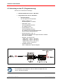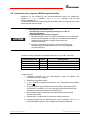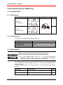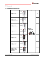
1
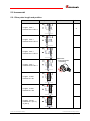
D Seite 2 - 22 GB Page 23 - 42 Incremental Encoder Ixx-58:2 OPTICAL, Generation 2 Explosionsschutzgehäuse / Explosion Protection Enclosure _A**58I:2 IxS-58:2 / IxH-58:2 _Zusätzliche Sicherheitshinweise _Additional safety instructions _Technische Daten _Electrical characteristics _Installation _Installation _Inbetriebnahme _Commissioning _Parametrierung _Parameterization _Fehlerursachen und Abhilfen _Cause of faults and remedies Benutzerhandbuch Schnittstelle / IEx: 437A14, IOx: 437A30 User Manual Interface TR - ECE - BA - DGB - 0113 - 01 / 11/20/2014 IxV-58:2 TR-Electronic GmbH D-78647 Trossingen Eglishalde 6 Tel.: (0049) 07425/228-0 Fax: (0049) 07425/228-33 E-mail: [email protected] http://www.tr-electronic.de Urheberrechtsschutz Dieses Handbuch, einschließlich den darin enthaltenen Abbildungen, ist urheberrechtlich geschützt. Drittanwendungen dieses Handbuchs, welche von den urheberrechtlichen Bestimmungen abweichen, sind verboten. Die Reproduktion, Übersetzung sowie die elektronische und fotografische Archivierung und Veränderung bedarf der schriftlichen Genehmigung durch den Hersteller. Zuwiderhandlungen verpflichten zu Schadenersatz. Änderungsvorbehalt Jegliche Änderungen, die dem technischen Fortschritt dienen, vorbehalten. Dokumenteninformation Ausgabe-/Rev.-Datum: Dokument-/Rev.-Nr.: Dateiname: Verfasser: 11/20/2014 TR - ECE - BA - DGB - 0113 - 01 TR-ECE-BA-DGB-0113-01.doc MÜJ Schreibweisen Kursive oder fette Schreibweise steht für den Titel eines Dokuments oder wird zur Hervorhebung benutzt. Courier-Schrift zeigt Text an, der auf dem Display bzw. Bildschirm sichtbar ist und Menüauswahlen von Software. ″< >″ weist auf Tasten der Tastatur Ihres Computers hin (wie etwa <RETURN>). TR-Electronic GmbH 2014, All Rights Reserved Page 2 of 44 Printed in the Federal Republic of Germany TR - ECE - BA - DGB - 0113 - 01 11/20/2014 Inhaltsverzeichnis Inhaltsverzeichnis ............................................................................................................................ 3 Änderungs-Index .............................................................................................................................. 4 1 Allgemeines ................................................................................................................................... 5 1.1 Geltungsbereich .............................................................................................................. 5 1.2 Verwendete Abkürzungen / Begriffe................................................................................ 6 2 Zusätzliche Sicherheitshinweise ................................................................................................. 7 2.1 Symbol- und Hinweis-Definition ...................................................................................... 7 2.2 Organisatorische Maßnahmen ........................................................................................ 7 2.3 Einsatz in explosionsfähigen Atmosphären .................................................................... 8 3 Technische Daten .......................................................................................................................... 9 3.1 Elektrische Kenndaten..................................................................................................... 9 3.2 Maximal zulässige elektrische Drehzahl ......................................................................... 11 4 Installation / Inbetriebnahme ........................................................................................................ 12 4.1 Anschluss – Hinweise...................................................................................................... 12 4.2 Kabelspezifikation ............................................................................................................ 12 4.3 Schirmauflage, bei Verwendung von Kabelverschraubungen ........................................ 13 4.4 Schaltausgang (optional) ................................................................................................. 15 4.5 Anbindung an den PC (Programmierung) ....................................................................... 16 4.5.1 Anbindung ohne separate TRWinProg-Schnittstelle ....................................... 17 5 Parametrierung über TRWinProg ................................................................................................ 18 5.1 Grundparameter .............................................................................................................. 18 5.1.1 Zählrichtung ..................................................................................................... 18 5.1.2 Anzahl Impulse ................................................................................................ 18 5.1.3 Presetfreigabe ................................................................................................. 18 5.2 Inkremental ...................................................................................................................... 19 5.2.1 Nullimpuls-Länge und -Lage............................................................................ 19 5.2.2 Spannung umschalten ..................................................................................... 20 5.3 Position (optional) ............................................................................................................ 20 5.3.1 Position ............................................................................................................ 20 5.3.2 Umdrehungen/Minute ...................................................................................... 20 5.3.3 Maximale Drehzahl/Minute .............................................................................. 20 5.3.4 Ausgabe Schaltausgang .................................................................................. 21 5.3.5 Schaltausgang ................................................................................................. 21 5.3.6 Schalter ............................................................................................................ 21 6 Fehlerursachen und Abhilfen....................................................................................................... 22 TR-Electronic GmbH 2014, All Rights Reserved Printed in the Federal Republic of Germany 11/20/2014 TR - ECE - BA - DGB - 0113 - 01 Page 3 of 44 Änderungs-Index Änderungs-Index Änderung Datum Index Erstausgabe 15.10.14 00 20.11.14 01 Hinweise für den Einsatz in explosionsgefährdeten Bereichen Zusatzparameter Schaltausgang, optional TR-Electronic GmbH 2014, All Rights Reserved Page 4 of 44 Printed in the Federal Republic of Germany TR - ECE - BA - DGB - 0113 - 01 11/20/2014 1 Allgemeines Das vorliegende schnittstellenspezifische Benutzerhandbuch beinhaltet folgende Themen: • Ergänzende Sicherheitshinweise zu den bereits in der Montageanleitung definierten grundlegenden Sicherheitshinweisen • Elektrische Kenndaten • Installation • Inbetriebnahme • Parametrierung • Fehlerursachen und Abhilfen Da die Dokumentation modular aufgebaut ist, stellt dieses Benutzerhandbuch eine Ergänzung zu anderen Dokumentationen wie z.B. Produktdatenblätter, Maßzeichnungen, Prospekte und der Montageanleitung etc. dar. Das Benutzerhandbuch kann kundenspezifisch im Lieferumfang enthalten sein, oder kann auch separat angefordert werden. 1.1 Geltungsbereich Dieses Benutzerhandbuch gilt ausschließlich für Mess-System-Baureihen gemäß nachfolgendem Typenschlüssel mit Inkremental Schnittstelle: A *1 Stelle A *1 *2 *3 (* 4) *5 *6 *2 *3 Bezeichnung A I E O V S H W 58 I :2 - (* 4) *5 - *6 *6 *6 *6 *6 Beschreibung Explosionsschutzgehäuse (ATEX); Inkremental-Encoder Optische Abtastung ≤ 10000 Impulse/Umdr. Optische Abtastung > 10000 Impulse/Umdr. Vollwelle Sacklochwelle Hohlwelle Seilzugbox (wire) Außendurchmesser ∅ 58 mm Inkremental-Encoder, nur bei ATEX-Ausführung Generation 2 Fortlaufende Nummer * = Platzhalter TR-Electronic GmbH 2014, All Rights Reserved Printed in the Federal Republic of Germany 11/20/2014 TR - ECE - BA - DGB - 0113 - 01 Page 5 of 44 Allgemeines Die Produkte sind durch aufgeklebte Typenschilder gekennzeichnet und sind Bestandteil einer Anlage. Es gelten somit zusammen folgende Dokumentationen: • • • • anlagenspezifische Betriebsanleitungen des Betreibers dieses Benutzerhandbuch Montageanleitung TR-ECE-BA-DGB-0035 optional: -Benutzerhandbuch mit Montageanleitung 1.2 Verwendete Abkürzungen / Begriffe A**58I:2 Explosionsschutzgehäuse ∅ 58 mm mit eingebautem MessSystem, alle Varianten EG Europäische Gemeinschaft EMV Elektro-Magnetische-Verträglichkeit ESD Elektrostatische Entladung (Electro Static Discharge) IEC Internationale Elektrotechnische Kommission NEC National Electrical Code VDE Verein Deutscher Elektrotechniker UZS Im Uhrzeigersinn GUZS Gegen den Uhrzeigersinn TR-Electronic GmbH 2014, All Rights Reserved Page 6 of 44 Printed in the Federal Republic of Germany TR - ECE - BA - DGB - 0113 - 01 11/20/2014 2 Zusätzliche Sicherheitshinweise 2.1 Symbol- und Hinweis-Definition bedeutet, dass Tod oder schwere Körperverletzung eintreten kann, wenn die entsprechenden Vorsichtsmaßnahmen nicht getroffen werden. bedeutet, dass eine leichte Körperverletzung eintreten kann, wenn die entsprechenden Vorsichtsmaßnahmen nicht getroffen werden. bedeutet, dass ein Sachschaden eintreten kann, wenn die entsprechenden Vorsichtsmaßnahmen nicht getroffen werden. bezeichnet wichtige Informationen bzw. Merkmale und Anwendungstipps des verwendeten Produkts. 2.2 Organisatorische Maßnahmen • Dieses Benutzerhandbuch muss ständig am Einsatzort des Mess-Systems griffbereit aufbewahrt werden. • Das mit Tätigkeiten am Mess-System beauftragte Personal muss vor Arbeitsbeginn - die Montageanleitung, Sicherheitshinweise“, insbesondere das Kapitel „Grundlegende - und dieses Benutzerhandbuch, insbesondere das Kapitel „Zusätzliche Sicherheitshinweise“, gelesen und verstanden haben. Dies gilt in besonderem Maße für nur gelegentlich, z. B. bei der Parametrierung des Mess-Systems, tätig werdendes Personal. TR-Electronic GmbH 2014, All Rights Reserved Printed in the Federal Republic of Germany 11/20/2014 TR - ECE - BA - DGB - 0113 - 01 Page 7 of 44 Zusätzliche Sicherheitshinweise 2.3 Einsatz in explosionsfähigen Atmosphären Für den Einsatz in explosionsfähigen Atmosphären wird das Standard Mess-System je nach Anforderung in ein entsprechendes Explosionsschutzgehäuse eingebaut. Die Produkte sind auf dem Typenschild mit einer zusätzlichen gekennzeichnet: Explosionsschutzgehäuse A**58I:2 -Kennzeichnung Gas: Dust: II 3G Ex II 3D Ex -Kennzeichnung -Benutzerhandbuch TR-ECE-BA-D-0114 Die „Bestimmungsgemäße Verwendung“, sowie alle Informationen für den gefahrlosen Einsatz des ATEX-konformen Mess-Systems in explosionsfähigen Atmosphären sind im -Benutzerhandbuch enthalten. Das in das Explosionsschutzgehäuse eingebaute Standard Mess-System kann somit in explosionsfähigen Atmosphären eingesetzt werden. Durch den Einbau in das Explosionsschutzgehäuse bzw. durch die Explosionsschutzanforderungen, ergeben sich Veränderungen an den ursprünglichen Eigenschaften des Mess-Systems. -Benutzerhandbuch ist zu überprüfen, ob die dort Anhand der Vorgaben im definierten Eigenschaften den applikationsspezifischen Anforderungen genügen. Der gefahrlose Einsatz erfordert zusätzliche Maßnahmen bzw. Anforderungen. Diese sind vor der Erstinbetriebnahme zu erfassen und müssen entsprechend umgesetzt werden. TR-Electronic GmbH 2014, All Rights Reserved Page 8 of 44 Printed in the Federal Republic of Germany TR - ECE - BA - DGB - 0113 - 01 11/20/2014 3 Technische Daten Die in den Technischen Daten angegebenen Informationen beziehen sich auf TRStandardgeräte. Das Typenschild und ein eventuell dem Gerät beigelegtes Datenblatt sind daher zu beachten ! 3.1 Elektrische Kenndaten Nennspannung - Kennwert .......................................................... 24 VDC - Grenzwerte, min/max ....................................... 4,5/32 VDC Nennstrom, typisch - Kennwert .......................................................... 50 mA - Zustand ............................................................ unbelastet Signalform ............................................................... Rechteck Inkrementalsignale, Rechteck - Kanäle .............................................................. K1+ K1- K2+ K2- Spurlage, elektrisch.......................................... 90 ° Nullimpuls - Kanal (Kanäle) ................................................. K0+ K0- Anzahl pro Umdrehung .................................... 1x Impulse/Umdrehung, Rechteck - IEx .................................................................... >= 2…<= 10000 - IOx .................................................................... >= 2…<= 70000 Ausgangsstufen - Programmierbar ............................................... TTL oder HTL Ausgangstreiber, TTL - Ausgangspegel ................................................ RS-422, 5 VDC - Laststrom ......................................................... <= 50 mA Ausgangstreiber, HTL - Ausgangspegel ................................................ Versorgungsspannung – 1,5 V - Laststrom ......................................................... <= 30 mA - Mindestspannung der Versorgung ................... > 8 VDC Drehzahl, elektrisch [1/min] ..................................... 1,5E+7 / Impulse pro Umdrehung TR-Electronic GmbH 2014, All Rights Reserved Printed in the Federal Republic of Germany 11/20/2014 TR - ECE - BA - DGB - 0113 - 01 Page 9 of 44 Technische Daten Parameter/Funktionen, änderbar ............................ Anzahl Impulse 0-Impuls K0: Impulslänge 0-Impuls K0: Anzahl Impulse Phasenlage: K0/K1/K2 Preset-Parameter Zählrichtung Ausgangsstufe (TTL/HTL) Parametrisierungsart ............................................... programmierbar Programmier - Tool.................................................. TR-Soft: TRWinProg Externe Eingänge - V/R ................................................................... Zählrichtung - Preset ............................................................... elektronische Justage - Logischer Zustand............................................ „0“ < +2V, „1“ = Versorgung Externe Ausgänge - Statusausgang ................................................. Geschwindigkeit - Ausgangspegel ................................................ <= 40 VDC, <= 50 mA - Ausgangsstufen ............................................... Open Collector - Ausstattung ...................................................... Option TR-Electronic GmbH 2014, All Rights Reserved Page 10 of 44 Printed in the Federal Republic of Germany TR - ECE - BA - DGB - 0113 - 01 11/20/2014 3.2 Maximal zulässige elektrische Drehzahl Die elektrische Maximaldrehzahl ist unabhängig von Maximaldrehzahl und lässt sich wie folgt berechnen: nelektrisch [1/min] = 1,5E+7 / Impulse pro Umdrehung der mechanischen nelektrisch = f (Imp./Umdr.): Berechnungsbeispiele: Mess-System, Typ IEx58:2 / IOx58:2 IOx58:2 1 Impulse / Umdr. max. elektrische Drehzahl [1/min] 1000 5000 10000 15000 20000 25000 30000 35000 40000 45000 50000 55000 60000 65000 70000 115000 3000 1500 1000 750 600 500 428 375 333 300 272 250 230 214 max. zulässige mechanische Drehzahl beachten! TR-Electronic GmbH 2014, All Rights Reserved Printed in the Federal Republic of Germany 11/20/2014 TR - ECE - BA - DGB - 0113 - 01 Page 11 of 44 Installation / Inbetriebnahme 4 Installation / Inbetriebnahme 4.1 Anschluss – Hinweise Die elektrischen Ausstattungsmerkmale werden hauptsächlich durch die variable Anschluss-Technik vorgegeben. Ob das Mess-System • externe Eingänge • externe Ausgänge • einen Nullimpuls oder invertierte Signalfolgen bei der Inkrementalschnittstelle unterstützt, wird deshalb durch die gerätespezifische Steckerbelegung definiert. Der Anschluss kann nur in Verbindung mit der gerätespezifischen Steckerbelegung vorgenommen werden! Bei der Auslieferung des Mess-Systems wird jeweils eine Steckerbelegung in gedruckter Form beigelegt. Die Steckerbelegungsnummer ist auch auf dem Typenschild des Mess-Systems vermerkt. 4.2 Kabelspezifikation Signal Empfehlung Versorgung min. 0,5mm2, paarig verseilt und geschirmt Spannungsabfall an den Zuleitungen beachten! Insbesondere beim 5 VDC-Betrieb ist darauf zu achten, dass am Mess-System der untere Grenzwert von 4,5 VDC nicht unterschritten wird. Um die Spannungsverluste an den Zuleitungen zu kompensieren, wird der Einsatz von Netzteilen mit „SenseFunktion“ empfohlen. K1+ / K1– K2+ / K2– min. 0,25mm2, jeweils paarig verseilt und geschirmt K0+ / K0– Ein-/Ausgänge 0,14 mm2 ... 0,25 mm2 Um eine hohe Störfestigkeit des Systems gegen elektromagnetische Störstrahlungen zu erzielen, müssen geschirmte Leitungen verwendet werden. Der Schirm sollte möglichst beidseitig und gut leitend über großflächige Schirmschellen an Schutzerde angeschlossen werden. Nur wenn die Maschinenerde gegenüber der Schaltschrankerde stark mit Störungen behaftet ist, sollte man den Schirm einseitig im Schaltschrank erden. Weiterhin ist zu beachten, dass die Datenleitungen möglichst separat von allen starkstromführenden Kabeln verlegt werden. Um einen sicheren und störungsfreien Betrieb zu gewährleisten, sind die einschlägigen Normen und Richtlinien zu beachten! Insbesondere sind die EMV-Richtlinie sowie die Schirmungs- und Erdungsrichtlinien in den jeweils gültigen Fassungen zu beachten! TR-Electronic GmbH 2014, All Rights Reserved Page 12 of 44 Printed in the Federal Republic of Germany TR - ECE - BA - DGB - 0113 - 01 11/20/2014 4.3 Schirmauflage, bei Verwendung von Kabelverschraubungen Die Schirmauflage erfolgt durch spezielle EMV-gerechte Kabelverschraubungen, bei denen die Kabelschirmung innen aufgelegt werden kann. Montage für Kabelverschraubung, Variante A Pos. 1 Überwurfmutter Pos. 2 Dichteinsatz Pos. 3 Kontakthülse Pos. 5 Einschraubstutzen 1. Schirmumflechtung / Schirmfolie auf Maß „X“ zurückschneiden. 2. Überwurfmutter (1) und Dichteinsatz / Kontakthülse (2) + (3) auf das Kabel aufschieben. 3. Die Schirmumflechtung / Schirmfolie um ca. 90° umbiegen (4). 4. Dichteinsatz / Kontakthülse (2) + (3) bis an die Schirmumflechtung / Schirmfolie schieben. 5. Einschraubstutzen (5) am Gehäuse montieren. 6. Dichteinsatz / Kontakthülse (2) + (3) in Einschraubstutzen (5) bündig zusammen stecken. 7. Überwurfmutter (1) mit Einschraubstutzen (5) verschrauben. TR-Electronic GmbH 2014, All Rights Reserved Printed in the Federal Republic of Germany 11/20/2014 TR - ECE - BA - DGB - 0113 - 01 Page 13 of 44 Installation / Inbetriebnahme Montage für Kabelverschraubung, Variante B Pos. 1 Pos. 2 Pos. 3 Pos. 4 Überwurfmutter Klemmeinsatz innerer O-Ring Einschraubstutzen 1. Schirmumflechtung / Schirmfolie auf Maß „X“ + 2mm zurückschneiden. 2. Überwurfmutter (1) und Klemmeneinsatz (2) auf das Kabel aufschieben. 3. Die Schirmumflechtung / Schirmfolie um ca. 90° umbiegen. 4. Klemmeinsatz (2) bis an die Schirmumflechtung / Schirmfolie schieben und das Geflecht um den Klemmeinsatz (2) zurückstülpen, so dass das Geflecht über den inneren O-Ring (3) geht, und nicht über dem zylindrischen Teil oder den Verdrehungsstegen liegt. 5. Einschraubstutzen (4) am Gehäuse montieren. 6. Klemmeinsatz (2) in Einschraubstutzen (4) einführen, so dass die Verdrehungsstege in die im Einschraubstutzen (4) vorgesehenen Längsnuten passen. 7. Überwurfmutter (1) mit Einschraubstutzen (4) verschrauben. TR-Electronic GmbH 2014, All Rights Reserved Page 14 of 44 Printed in the Federal Republic of Germany TR - ECE - BA - DGB - 0113 - 01 11/20/2014 4.4 Schaltausgang (optional) Optional kann das Mess-System mit einem Open-Collector – Schaltausgang ausgestattet sein. Prinzip-Schaltbild Damit der Schaltausgang nicht beschädigt wird, muss der externe Vorwiderstand Rext so gewählt werden, dass der Maximal-Strom von 50 mA nicht überschritten wird. Die Funktion des Schaltausgangs kann TRWinProg eingestellt werden, siehe Kapitel Position (optional), ab Seite 20. TR-Electronic GmbH 2014, All Rights Reserved Printed in the Federal Republic of Germany 11/20/2014 TR - ECE - BA - DGB - 0113 - 01 Page 15 of 44 Installation / Inbetriebnahme 4.5 Anbindung an den PC (Programmierung) Was wird von TR-Electronic benötigt? Schaltschrankmodul Art.-Nr.: 490-00101 Programmier-Set Art.-Nr.: 490-00310: • Kunststoff-Koffer, mit nachfolgenden Komponenten: – USB PC-Adapter V4 Umsetzung USB <--> RS485 – USB-Kabel 1,00 m Verbindungskabel zwischen PC-Adapter und PC – Flachbandkabel 1,30 m Verbindungskabel zwischen PC-Adapter und TR-Schaltschrank-Modul (15-pol. SUB-D Buchse/Stecker) – Steckernetzteil 24 V DC, 1A Versorgungsmöglichkeit des angeschlossenen Gerätes über den PC-Adapter – Software- und Support-CD - USB-Treiber, Soft-Nr.: 490-00421 - TRWinProg, Soft-Nr.: 490-00416 - EPROGW32, Soft-Nr.: 490-00418 - LTProg, Soft-Nr.: 490-00415 – Installationsanleitung TR-E-TI-DGB-0074, Deutsch/Englisch Für den Betrieb unter Windows 7 wird der USB PC-Adapter HID (V5), Art-Nr.: 490-00313 benötigt. TR-Electronic GmbH 2014, All Rights Reserved Page 16 of 44 Printed in the Federal Republic of Germany TR - ECE - BA - DGB - 0113 - 01 11/20/2014 4.5.1 Anbindung ohne separate TRWinProg-Schnittstelle Abhängig von der Ausführung des Anschluss-Steckers können die TRWinProgSignale Ser.Program+ (RS485+) und Ser.Program- (RS485-) nicht auf dem Stecker aufgelegt sein. In diesem Fall können die Differenzsignale des Nullimpulses zur Programmierung des Mess-Systems benutzt werden. ● Beschädigung des Gerätes durch - Einspeisung von Versorgungsspannungen > 5 V DC im Programmier-Modus - Doppelbelegung der Anschluss-Signale Das Mess-System muss im Programmier-Modus mit 5 V DC betrieben werden und darf deshalb nicht über das 24V-Steckernetzteil des PCAdapters versorgt werden, sondern separat über das Schaltschrankmodul. Bei der Programmierung dürfen nur die zur Programmierung benötigten Signale angeschlossen sein, siehe nachfolgendes Anschluss-Schema. Anschluss-Schema, Beispiel mit Schaltschrankmodul PT-6, Art-Nr.: 490-00101 Klemmenname PT-6 0VGND US DatenDaten+ Signal 0V + 5 V DC RS485RS485+ Mess-System Ground IN Supply Voltage IN Channel Reference inverted (K0-) Channel Reference (K0+) Vorgehensweise: Verbindung zwischen PC und Mess-System mittels PC-Adapter und Schaltschrankmodul herstellen. TRWinProg-Programm starten. In der TRWinProg-Programm-Oberfläche die TRWinprog-Kommunikation starten ( ). Versorgungsspannung des Mess-Systems einschalten. Das Mess-System wird darauf hin innerhalb ≤ 3 s in den Programmier-Modus geschaltet. Die Ausgabe der Inkremental-Signale wird unterbrochen. Nach erfolgter Programmierung die Versorgungsspannung des MessSystems ausschalten. Verdrahtung zur Programmierung des Mess-Systems aufheben. Versorgungsspannung des Mess-Systems erneut einschalten. Nach ≤ 3 s beginnt das Mess-System mit der Ausgabe der Inkremental-Signale. TR-Electronic GmbH 2014, All Rights Reserved Printed in the Federal Republic of Germany 11/20/2014 TR - ECE - BA - DGB - 0113 - 01 Page 17 of 44 Parametrierung über TRWinProg 5 Parametrierung über TRWinProg 5.1 Grundparameter 5.1.1 Zählrichtung Auswahl Beschreibung Bedingungen Steigend Default X (K1 voreilend) Fallend (K1 nacheilend) 5.1.2 Anzahl Impulse Festlegung der ausgegebenen Impulse/Umdrehung. Untergrenze 2 Obergrenze IEx 10000 Obergrenze IOx 70000 Programmierbarkeit einschrittig 5.1.3 Presetfreigabe Gefahr von Körperverletzung und Sachschaden durch einen Istwertsprung bei Ausführung der Preset-Justage-Funktion! • Die Preset-Justage-Funktion sollte nur im Mess-System-Stillstand ausgeführt werden, bzw. muss der resultierende Istwertsprung programmtechnisch und anwendungstechnisch erlaubt sein! Die Preset-Justage-Funktion kann nur ausgeführt werden, wenn das Eingangssignal >50 ms statisch am Eingang anliegt. Nach ca. 0,5 s wird das Nullimpuls-Signal am Ausgang gesetzt. Wird der Preset-Eingang nicht benötigt, sollte er zur Störunterdrückung gesperrt werden. Auswahl Beschreibung freigegeben Preset-Justage-Funktion aktiv gesperrt Preset-Justage-Funktion inaktiv TR-Electronic GmbH 2014, All Rights Reserved Page 18 of 44 Default X Printed in the Federal Republic of Germany TR - ECE - BA - DGB - 0113 - 01 11/20/2014 5.2 Inkremental 5.2.1 Nullimpuls-Länge und -Lage Auswahl Beschreibung Bedingungen Länge= 1/ 90° / Lage K2=1 & K1=1 Default X Länge= 1/ 90° / Lage K2=0 & K1=0 Länge= 1/ 90° / Lage K2=1 & K1=0 Parameter: • Zählrichtung steigend Länge= 1/ 90° / Lage K2=0 & K1=1 Länge= 1/ 180°/ Lage K0 = K1 Länge= 1/ 180°/ Lage K0 = K2 Länge= 1/ 270°/ Lage K0 = (K1=1) oder (K2=1) TR-Electronic GmbH 2014, All Rights Reserved Printed in the Federal Republic of Germany 11/20/2014 TR - ECE - BA - DGB - 0113 - 01 Page 19 of 44 Parametrierung über TRWinProg 5.2.2 Spannung umschalten Auswahl Beschreibung RS422 Ausgangstreiber: RS422-Ausgangsstufe Pegel = 5 VDC Ausgangstreiber: Gegentakt-Ausgangsstufe Pegel = Versorgungsspannung HTL Die Versorgungsspannung muss > 8 VDC betragen. 5.3 Position (optional) 5.3.1 Position Im Onlinezustand wird im Feld Position die aktuelle Mess-System-Position in Schritten angezeigt. Resultierende Impulse = Anzahl Schritte/4 Gefahr von Körperverletzung und Sachschaden durch einen Istwertsprung bei Ausführung der Justage-Funktion! • Die Justage-Funktion sollte nur im Mess-System-Stillstand ausgeführt werden, bzw. muss der resultierende Istwertsprung programmtechnisch und anwendungstechnisch erlaubt sein! Durch Eingabe eines Wertes in das Feld Position kann das Mess-System auf den gewünschten Positionswert justiert werden. Der Wert wird mit Ausführung der Funktion Daten zum Gerät schreiben übernommen. Untergrenze 0 Obergrenze (programmierte Anzahl Impulse/Umdrehung * 4) – 1 5.3.2 Umdrehungen/Minute Im Onlinezustand wird im Feld Umdrehungen/Minute die aktuelle Mess-SystemDrehzahl als Betragswert in min-1 angezeigt. 5.3.3 Maximale Drehzahl/Minute Eingabe der Schaltschwelle [min-1] für den Schaltausgang „Geschwindigkeit“. Schaltausgang = aktiv, wenn Drehzahl > Schaltschwelle. Aktivierung und zusätzliche Einstellungsmöglichkeiten zum Schaltausgang siehe nachfolgende Parameter. TR-Electronic GmbH 2014, All Rights Reserved Page 20 of 44 Printed in the Federal Republic of Germany TR - ECE - BA - DGB - 0113 - 01 11/20/2014 5.3.4 Ausgabe Schaltausgang Auswahl Beschreibung Default Nicht speichern Schaltausgang = aktiv, wenn Drehzahl > Schaltschwelle Schaltausgang = inaktiv, wenn Drehzahl < Schaltschwelle X Schaltausgang = aktiv, wenn Drehzahl > Schaltschwelle Diese Information wird gespeichert, bis eine Rücksetzung erfolgt: Speichern ● Deaktivieren/Aktivieren des Schaltausgangs über Parameter Schalter oder ● Aus-/Einschalten der Versorgungsspannung Einstellung der Schaltschwelle siehe Parameter Maximale Drehzahl/Minute Aktivierung des Schaltausgangs siehe Parameter Schalter 5.3.5 Schaltausgang Auswahl Beschreibung Nicht negiert Schaltausgang = High-aktiv Schaltausgang = Low-aktiv Negiert Default X 5.3.6 Schalter Auswahl Beschreibung Nicht aktiv Schaltausgang deaktiviert Schaltausgang aktiviert Aktiv X TR-Electronic GmbH 2014, All Rights Reserved Printed in the Federal Republic of Germany 11/20/2014 Default TR - ECE - BA - DGB - 0113 - 01 Page 21 of 44 Fehlerursachen und Abhilfen 6 Fehlerursachen und Abhilfen Störung Ursache Abhilfe Vibrationen, Schläge und Stöße werden mit so genannten starke Vibrationen „Schockmodulen“ gedämpft. Wenn der Fehler trotz dieser Maßnahme wiederholt auftritt, muss das Mess-System getauscht werden. Positionssprünge Elektrische Gegen elektrische Störungen helfen eventuell isolierende des Mess-Systems Störungen Flansche EMV geschirmte Kabel. und Kupplungen aus Kunststoff, sowie Übermäßige axiale und radiale Belastung der Welle oder einen Defekt der Abtastung. Kupplungen vermeiden mechanische Belastungen der Welle. Wenn der Fehler trotz dieser Maßnahme weiterhin auftritt, muss das Mess-System getauscht werden. TR-Electronic GmbH 2014, All Rights Reserved Page 22 of 44 Printed in the Federal Republic of Germany TR - ECE - BA - DGB - 0113 - 01 11/20/2014 User Manual Ixx-58:2 Incremental TR-Electronic GmbH 2014, All Rights Reserved Printed in the Federal Republic of Germany 11/20/2014 TR - ECE - BA - DGB - 0113 - 01 Page 23 of 44 TR-Electronic GmbH D-78647 Trossingen Eglishalde 6 Tel.: (0049) 07425/228-0 Fax: (0049) 07425/228-33 E-mail: [email protected] http://www.tr-electronic.de Copyright protection This Manual, including the illustrations contained therein, is subject to copyright protection. Use of this Manual by third parties in contravention of copyright regulations is forbidden. Reproduction, translation as well as electronic and photographic archiving and modification require the written content of the manufacturer. Offenders will be liable for damages. Subject to amendments Any technical changes that serve the purpose of technical progress, reserved. Document information Release date/Rev. date: Document rev. no.: File name: Author: 11/20/2014 TR - ECE - BA - DGB - 0113 - 01 TR-ECE-BA-DGB-0113-01.doc MÜJ Font styles Italic or bold font styles are used for the title of a document or are used for highlighting. Courier font displays text, which is visible on the display or screen and software menu selections. ″< > ″ indicates keys on your computer keyboard (such as <RETURN>). TR-Electronic GmbH 2014, All Rights Reserved Page 24 of 44 Printed in the Federal Republic of Germany TR - ECE - BA - DGB - 0113 - 01 11/20/2014 Contents Contents ............................................................................................................................................ 25 Revision index .................................................................................................................................. 26 1 General information ...................................................................................................................... 27 1.1 Applicability ...................................................................................................................... 27 1.2 Abbreviations and definitions........................................................................................... 28 2 Additional safety instructions ...................................................................................................... 29 2.1 Definition of symbols and instructions ............................................................................. 29 2.2 Organizational measures................................................................................................. 29 2.3 Usage in explosive atmospheres .................................................................................... 30 3 Technical data................................................................................................................................ 31 3.1 Electrical characteristics .................................................................................................. 31 3.2 Max. permissible electrical speed ................................................................................... 33 4 Installation / Commissioning ....................................................................................................... 34 4.1 Connection – notes .......................................................................................................... 34 4.2 Cable definition ................................................................................................................ 34 4.3 Shield cover, when using cable screw glands ................................................................. 35 4.4 Switching output (optional) .............................................................................................. 37 4.5 Connection to the PC (programming).............................................................................. 38 4.5.1 Connection without separate TRWinProg interface ........................................ 39 5 Parameterization via TRWinProg ................................................................................................. 40 5.1 Basic-Parameters ............................................................................................................ 40 5.1.1 Count direction ................................................................................................. 40 5.1.2 Number of impulses ......................................................................................... 40 5.1.3 Preset function ................................................................................................. 40 5.2 Incremental ...................................................................................................................... 41 5.2.1 Zero pulse length and position ........................................................................ 41 5.2.2 Change over output voltage ............................................................................ 42 5.3 Position (optional) ............................................................................................................ 42 5.3.1 Position ............................................................................................................ 42 5.3.2 Revolutions/Minute .......................................................................................... 42 5.3.3 Maximum Speed/Minute .................................................................................. 42 5.3.4 Output switching output ................................................................................... 43 5.3.5 Switching output .............................................................................................. 43 5.3.6 Switch .............................................................................................................. 43 6 Causes of faults and remedies .................................................................................................... 44 TR-Electronic GmbH 2014, All Rights Reserved Printed in the Federal Republic of Germany 11/20/2014 TR - ECE - BA - DGB - 0113 - 01 Page 25 of 44 Revision index Revision index Revision First release Date Index 10/15/14 00 11/20/14 01 Notes for use in explosive atmospheres Additional parameter for the switching output, optional TR-Electronic GmbH 2014, All Rights Reserved Page 26 of 44 Printed in the Federal Republic of Germany TR - ECE - BA - DGB - 0113 - 01 11/20/2014 1 General information The interface specific User Manual includes the following topics: • Safety instructions in additional to the basic safety instructions defined in the Assembly Instructions • Electrical characteristics • Installation • Commissioning • Parameterization • Causes of faults and remedies As the documentation is arranged in a modular structure, this User Manual is supplementary to other documentation, such as product datasheets, dimensional drawings, leaflets and the assembly instructions etc. The User Manual may be included in the customer’s specific delivery package or it may be requested separately. 1.1 Applicability This User Manual applies exclusively to measuring system models according to the following type designation code with Incremental interface: A *1 Position A *1 *2 *3 (* 4) *5 *6 *2 *3 Notation A I E O V S H W 58 I :2 - (* 4) *5 - *6 *6 *6 *6 Description Explosion protection enclosure (ATEX); Incremental-Encoder Optical scanning unit ≤ 10000 impulses/rev. Optical scanning unit > 10000 impulses/rev. Solid shaft Blind shaft Hollow through shaft Rope length transmitter (wire) External diameter ∅ 58 mm Incremental-Encoder, ATEX only Generation 2 Consecutive number TR-Electronic GmbH 2014, All Rights Reserved Printed in the Federal Republic of Germany 11/20/2014 *6 TR - ECE - BA - DGB - 0113 - 01 Page 27 of 44 General information The products are labelled with affixed nameplates and are components of a system. The following documentation therefore also applies: • • • • the operator’s operating instructions specific to the system this User Manual Assembly instructions TR-ECE-BA-DGB-0035 optional: -User Manual with assembly instructions 1.2 Abbreviations and definitions A**58I:2* Explosion protection enclosure ∅ 58 mm with integrated measuring system, all variants EC European Community EMC Electro Magnetic Compatibility ESD Electro Static Discharge IEC International Electrotechnical Commission NEC National Electrical Code VDE German Electrotechnicians Association CW Clockwise CCW Counterclockwise TR-Electronic GmbH 2014, All Rights Reserved Page 28 of 44 Printed in the Federal Republic of Germany TR - ECE - BA - DGB - 0113 - 01 11/20/2014 2 Additional safety instructions 2.1 Definition of symbols and instructions means that death or serious injury can occur if the required precautions are not met. means that minor injuries can occur if the required precautions are not met. means that damage to property can occur if the required precautions are not met. indicates important information or features and application tips for the product used. 2.2 Organizational measures • This User Manual must always kept accessible at the site of operation of the measurement system. • Prior to commencing work, personnel working with the measurement system must have read and understood - the assembly instructions, in particular the chapter "Basic safety instructions", - and this User Manual, in particular the chapter "Additional safety instructions". This particularly applies for personnel who are only deployed occasionally, e.g. at the parameterization of the measurement system. TR-Electronic GmbH 2014, All Rights Reserved Printed in the Federal Republic of Germany 11/20/2014 TR - ECE - BA - DGB - 0113 - 01 Page 29 of 44 Additional safety instructions 2.3 Usage in explosive atmospheres When used in explosive atmospheres, the standard measuring system has to be installed in an appropriate explosion protective enclosure and subject to requirements. The products are labeled with an additional Explosion Protection Enclosure A**58I:2* marking on the nameplate: Marking Gas: Dust: II 3G Ex II 3D Ex -User Manual TR-ECE-BA-GB-0114 The “intended use” as well as any information on the safe usage of the ATEXUser compliant measuring system in explosive atmospheres are contained in the Manual. Standard measuring systems that are installed in the explosion protection enclosure can therefore be used in explosive atmospheres. When the measuring system is installed in the explosion protection enclosure, which means that it meets explosion protection requirements, the properties of the measuring system will no longer be as they were originally. User Manual, please check whether the Following the specifications in the properties defined in that manual meet the application-specific requirements. Fail-safe usage requires additional measures and requirements. Such measures and requirements must be determined prior to initial commissioning and must be taken and met accordingly. TR-Electronic GmbH 2014, All Rights Reserved Page 30 of 44 Printed in the Federal Republic of Germany TR - ECE - BA - DGB - 0113 - 01 11/20/2014 3 Technical data The information specified in the Technical Data refers to the TR standard devices. The nameplate and any datasheet included with the device are therefore to be observed ! 3.1 Electrical characteristics Nominal voltage - Specific value ................................................... 24 VDC - Limit values, min/max....................................... 4.5/32 VDC Nominal current, typically - Specific value ................................................... 50 mA - Condition .......................................................... unloaded Signal form .............................................................. Square Incremental signals, square - Channels .......................................................... K1+ K1- K2+ K2- Phase position, electrically ............................... 90 ° Zero pulse - Channel (Channels) ......................................... K0+ K0- Number of revolutions ...................................... 1x Impulses, square wave - IEx .................................................................... >= 2…<= 10000 - IOx .................................................................... >= 2…<= 70000 Output stages - Programmable .................................................. TTL or HTL Output driver, TTL - Output level ...................................................... RS-422, 5 VDC - Load current ..................................................... <= 50 mA Output driver, HTL - Output level ...................................................... Supply voltage – 1.5 V - Load current ..................................................... <= 30 mA - Minimum voltage of the supply ........................ > 8 VDC Speed, electrically [1/min] ....................................... 1.5E+7 / Impulses per revolution TR-Electronic GmbH 2014, All Rights Reserved Printed in the Federal Republic of Germany 11/20/2014 TR - ECE - BA - DGB - 0113 - 01 Page 31 of 44 Technical data Parameter/Function, changeable ............................ Number of pulses 0-Pulse K0: Pulse length 0-Pulse K0: Number of pulses Phase position: K0/K1/K2 Preset parameter Counting direction Output stage (TTL/HTL) Type of parametrization ........................................... programmable Programming - Tool ................................................. TR-Soft: TRWinProg External inputs - F/R.................................................................... Count direction - Preset ............................................................... electronic adjustment - Logic level ........................................................ "0" < +2V, "1" = Supply External outputs - Status output .................................................... Speed - Output level ...................................................... <= 40 VDC, <= 50 mA - Output stages ................................................... Open Collector - Equipment ........................................................ Option TR-Electronic GmbH 2014, All Rights Reserved Page 32 of 44 Printed in the Federal Republic of Germany TR - ECE - BA - DGB - 0113 - 01 11/20/2014 3.2 Max. permissible electrical speed The electrical maximum speed is independent of the mechanical maximum speed and can be calculated as follows: nelectrical [1/min] = 1.5E+7 / Impulses per revolution nelectrical = f (Imp./Rev.): Examples of calculations: Measuring system type Impulses / Rev. max. electrical speed [1/min] 1000 5000 10000 15000 20000 25000 30000 35000 40000 45000 50000 55000 60000 65000 70000 215000 IEx58:2 / IOx58:2 IOx58:2 2 3000 1500 1000 750 600 500 428 375 333 300 272 250 230 214 Observe the max. permissible mechanical speed! TR-Electronic GmbH 2014, All Rights Reserved Printed in the Federal Republic of Germany 11/20/2014 TR - ECE - BA - DGB - 0113 - 01 Page 33 of 44 Installation / Commissioning 4 Installation / Commissioning 4.1 Connection – notes Mainly, the electrical characteristics are defined by the variable connection technique. Whether the measuring system supports • external inputs • external outputs • a reference pulse or inverted signal sequences of the incremental interface is therefore defined by the device specific pin assignment. The connection can be made only in connection with the device specific pin assignment! At the delivery of the measuring system one device specific pin assignment in printed form is enclosed. The number of the pin assignment is also noted on the nameplate of the measuring system. 4.2 Cable definition Signal Recommendation Supply voltage min. 0,5 mm2, twisted in pairs and shielded Consider voltage drops at the supply cables! Especially in the 5 VDC operation it must be ensured that the limiting value of 4.5 VDC at the measuring system is not fallen below. In order to compensate the voltage losses at the supply cables, the usage of power packs with "Sense function" is recommended. K1+ / K1– K2+ / K2– min. 0,25 mm2, each twisted in pairs and shielded K0+ / K0– Input / Output 0,14 mm2 ... 0,25 mm2 Shielded cables must be used to achieve high electromagnetic interference stability. The shielding should be connected with low resistance to protective ground using large shield clips at both ends. Only if the machine ground is heavily contaminated with interference towards the control cabinet ground the shield should be grounded in the control cabinet only. It is also important that the data-lines are routed separate from power current carrying cables if at all possible. The applicable standards and guidelines are to be observed to insure safe and stable operation! In particular, the applicable EMC directive and the shielding and grounding guidelines must be observed! TR-Electronic GmbH 2014, All Rights Reserved Page 34 of 44 Printed in the Federal Republic of Germany TR - ECE - BA - DGB - 0113 - 01 11/20/2014 4.3 Shield cover, when using cable screw glands The shield cover is connected with a special EMC cable gland, whereby the cable shielding is fitted on the inside. Cable gland assembly, variant A Pos. 1 Nut Pos. 2 Seal Pos. 3 Contact bush Pos. 5 Screw socket 1. Cut shield braid / shield foil back to dimension "X". 2. Slide the nut (1) and seal / contact bush (2) + (3) over the cable. 3. Bend the shield braining / shield foil to 90° (4). 4. Slide seal / contact bush (2) + (3) up to the shield braining / shield foil. 5. Assemble screw socket (5) on the housing. 6. Push seal / contact bush (2) + (3) flush into the screw socket (5). 7. Screw the nut (1) to the screw socket (5). TR-Electronic GmbH 2014, All Rights Reserved Printed in the Federal Republic of Germany 11/20/2014 TR - ECE - BA - DGB - 0113 - 01 Page 35 of 44 Installation / Commissioning Cable gland assembly, variant B Pos. 1 Pos. 2 Pos. 3 Pos. 4 Nut Clamping ring Inner O-ring Screw socket 1. Cut shield braid / shield foil back to dimension "X" + 2mm. 2. Slide the nut (1) and clamping ring (2) over the cable. 3. Bend the shield braining / shield foil to approx. 90°. 4. Push clamping ring (2) up to the shield braid / shield foil and wrap the braiding back around the clamping ring (2), such that the braiding goes around the inner O-ring (3), and is not above the cylindrical part or the torque supports. 5. Assemble screw socket (4) on the housing. 6. Insert the clamping ring (2) in the screw socket (4) such that the torque supports fit in the slots in the screw socket (4). 7. Screw the nut (1) to the screw socket (4). TR-Electronic GmbH 2014, All Rights Reserved Page 36 of 44 Printed in the Federal Republic of Germany TR - ECE - BA - DGB - 0113 - 01 11/20/2014 4.4 Switching output (optional) Optionally the measuring system can be equipped with an Open Collector switching output. Schematic - Circuit diagram So that the switching output is not damaged, the external pre-resistor Rext must be selected in such a way that the maximum current of 50 mA is not exceeded. The function of the switching output can be adjusted in TRWinProg, see chapter Position (optional), as from page 42. TR-Electronic GmbH 2014, All Rights Reserved Printed in the Federal Republic of Germany 11/20/2014 TR - ECE - BA - DGB - 0113 - 01 Page 37 of 44 Installation / Commissioning 4.5 Connection to the PC (programming) What will be needed by TR-Electronic? Switch cabinet module Order-No.: 490-00101 Programming set Order-No.: 490-00310: • Plastic case, with the following components: – USB PC adapter V4 Conversion USB <--> RS485 – USB cable 1.00 m Connection cable between PC adapter and PC – Flat ribbon cable 1.30 m Connection cable between PC adapter and TR switch cabinet module (15-pol. SUB-D female/male) – Plug Power Supply Unit 24 V DC, 1A The connected device can be supplied via the PC adapter – Software- and Support-CD - USB driver, Soft-No.: 490-00421 - TRWinProg, Soft-No.: 490-00416 - EPROGW32, Soft-No.: 490-00418 - LTProg, Soft-No.: 490-00415 – Installation Guide TR-E-TI-DGB-0074, German/English For operation with Windows 7 the USB PC adapter HID (V5), order no.: 490-00313 must be used. TR-Electronic GmbH 2014, All Rights Reserved Page 38 of 44 Printed in the Federal Republic of Germany TR - ECE - BA - DGB - 0113 - 01 11/20/2014 4.5.1 Connection without separate TRWinProg interface Dependent on the type of the plug the TRWinProg signals Ser.Program+ (RS485+) and Ser.Program- (RS485-) cannot be connected on the plug. In this case the differential signals of the zero-impulse can be used for the programming of the measuring system. ● Damage to the device by - feeding of supply voltages > 5 V DC in the programming mode - double pin definition of the connection signals In the programming mode the measuring system must be supplied with 5 V DC. In this case the 24V - plug power supply unit of the PC adapter must not to be used. The measuring system must be supplied separate about the switch cabinet module. In case of programming only the signals required for the programming may be connected, see following connection diagram. Connection diagram, example with switch cabinet module PT-6, Order-No.: 490-00101 Clamps PT-6 0VGND US Daten- (Data-) Daten+ (Data+) Signal 0V + 5 V DC RS485RS485+ Measuring system Ground IN Supply Voltage IN Channel Reference inverted (K0-) Channel Reference (K0+) Procedure: Connect PC and measuring system by means of the PC adapter and switch cabinet module. Start the TRWinProg program Start the TRWinProg communication ( ) in the TRWinprog user interface. Switch on the supply voltage of the measuring system. The measuring system is switched into the programming mode within ≤ 3 s. The output of the incremental signals is interrupted. If the programming is finished switch off the supply voltage of the measuring system. Disconnect the wiring for programming the measuring system. Switch on the supply voltage of the measuring system again. After ≤ 3 s the measuring system begins with the output of the incremental signals. TR-Electronic GmbH 2014, All Rights Reserved Printed in the Federal Republic of Germany 11/20/2014 TR - ECE - BA - DGB - 0113 - 01 Page 39 of 44 Parameterization via TRWinProg 5 Parameterization via TRWinProg 5.1 Basic-Parameters 5.1.1 Count direction Selection Description Increasing (K1, leading signal) Conditions Default X Decreasing (K1, lagging signal) 5.1.2 Number of impulses Specification of the output pulses per revolution. Lower limit 2 Upper limit IEx 10000 Upper limit IOx 70000 Programmability 1-step 5.1.3 Preset function Risk of injury and damage to property by an actual value jump when the Preset adjustment function is performed! • The Preset function should only be performed when the measuring system is at rest, otherwise the resulting actual value jump must be permitted in the program and application! The Preset function only can be executed if the input signal is present statically for >50 ms at the input. After approx. 0.5s the zero pulse signal at the output is set. If the Preset function input is not used, he should be disabled to suppress interference. Selection Description In use Preset function active Not in use Preset function inactive TR-Electronic GmbH 2014, All Rights Reserved Page 40 of 44 Default X Printed in the Federal Republic of Germany TR - ECE - BA - DGB - 0113 - 01 11/20/2014 5.2 Incremental 5.2.1 Zero pulse length and position Selection Description Conditions Length= 1/ 90° / Position K2=1 & K1=1 Default X Length= 1/ 90° / Position K2=0 & K1=0 Length= 1/ 90° / Position K2=1 & K1=0 Parameter: • Count direction increasing Length= 1/ 90° / Position K2=0 & K1=1 Length= 1/ 180°/ Position K0 = K1 Length= 1/ 180°/ Position K0 = K2 Length= 1/ 270°/ Position K0 = (K1=1) or (K2=1) TR-Electronic GmbH 2014, All Rights Reserved Printed in the Federal Republic of Germany 11/20/2014 TR - ECE - BA - DGB - 0113 - 01 Page 41 of 44 Parameterization via TRWinProg 5.2.2 Change over output voltage Selection Description RS422 Output driver: RS422; Level = 5 VDC Output driver: Push-Pull; Level = Supply voltage HTL The supply voltage must be > 8 VDC 5.3 Position (optional) 5.3.1 Position In the online state in the field Position the current measuring system position in steps is displayed. Resultant impulses = Number of steps/4 Risk of injury and damage to property by an actual value jump when the adjustment function is performed! • The adjustment function should only be performed when the measuring system is at rest, otherwise the resulting actual value jump must be permitted in the program and application! With entering of a value into the field Position the measuring system can be adjusted on the desired position value. The new position is set if the function Data write to device is executed. Lower limit 0 Upper limit (programmed number of impulses/revolution * 4) – 1 5.3.2 Revolutions/Minute In the online state in the field Revolutions/Minute the current measuring system speed in min-1 is displayed. The value is output without sign. 5.3.3 Maximum Speed/Minute Input of the switching threshold [min-1] for the switching output “Speed”. Switching output = active, if the speed > switching threshold. Activation and additional setting possibilities for the switching output see following parameters. TR-Electronic GmbH 2014, All Rights Reserved Page 42 of 44 Printed in the Federal Republic of Germany TR - ECE - BA - DGB - 0113 - 01 11/20/2014 5.3.4 Output switching output Selection Description Default Not saved Switching output = active, if speed > switching threshold Switching output = inactive, if speed < switching threshold X Switching output = active, if speed > switching threshold Saved This information is saved until a RESET is carried out: ● Deactivation/Activation of the switching output about parameter Switch or ● Switching OFF/ON of the supply voltage Setting of the switching threshold, see parameter Maximum Speed/Minute Activation of the switching output, see parameter Switch 5.3.5 Switching output Selection Description Not inverted Inverted Switching output = high active Switching output = low active Selection Description Not active Switching output deactivated Switching output activated Default X 5.3.6 Switch Active X TR-Electronic GmbH 2014, All Rights Reserved Printed in the Federal Republic of Germany 11/20/2014 Default TR - ECE - BA - DGB - 0113 - 01 Page 43 of 44 Causes of faults and remedies 6 Causes of faults and remedies Fault Cause Remedy Vibrations, impacts and shocks are dampened with "shock Strong vibrations modules". If the error recurs despite this measure, the measuring system must be replaced. Position skips Electrical faults Perhaps isolated flanges and couplings made of plastic of the measuring EMC help against electrical faults, as well as shielded cables. system Extreme axial and radial load on the shaft may result in a scanning defect. Couplings prevent mechanical stress on the shaft. If the error still occurs despite this measure, the measuring system must be replaced. TR-Electronic GmbH 2014, All Rights Reserved Page 44 of 44 Printed in the Federal Republic of Germany TR - ECE - BA - DGB - 0113 - 01 11/20/2014