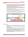
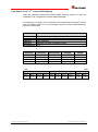
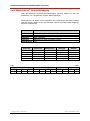
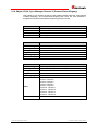
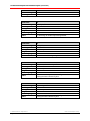
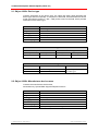
1
+Incremental D Seite 2 - 88 GB Page 89 - 176 Absolute Encoder C__-58 CEK-58 COK-58 _Zusätzliche Sicherheitshinweise _Installation _Inbetriebnahme CEH-58 / COH-58 CES-58 / COS-58 _Konfiguration / Parametrierung _Fehlerursachen und Abhilfen _Additional safety instructions _Installation • Software/Support DVD: 490-01001 - Soft-No.: 490-00423 _Commissioning _Configuration / Parameterization _Cause of faults and remedies Benutzerhandbuch User Manual 4377EC / 4377E2 / 43782C / 43782D / 43782E / 43782F / 4377D5 / 4377D6 / 4377D7 / 4377D8 TR - ECE - BA - DGB - 0094 - 08 09/29/2014 CEV-58 COV-58 TR-Electronic GmbH D-78647 Trossingen Eglishalde 6 Tel.: (0049) 07425/228-0 Fax: (0049) 07425/228-33 E-mail: [email protected] http://www.tr-electronic.de Urheberrechtsschutz Dieses Handbuch, einschließlich den darin enthaltenen Abbildungen, ist urheberrechtlich geschützt. Drittanwendungen dieses Handbuchs, welche von den urheberrechtlichen Bestimmungen abweichen, sind verboten. Die Reproduktion, Übersetzung sowie die elektronische und fotografische Archivierung und Veränderung bedarf der schriftlichen Genehmigung durch den Hersteller. Zuwiderhandlungen verpflichten zu Schadenersatz. Änderungsvorbehalt Jegliche Änderungen, die dem technischen Fortschritt dienen, vorbehalten. Dokumenteninformation Ausgabe-/Rev.-Datum: Dokument-/Rev.-Nr.: Dateiname: Verfasser: 09/29/2014 TR - ECE - BA - DGB - 0094 - 08 TR-ECE-BA-DGB-0094-08.docx MÜJ Schreibweisen Kursive oder fette Schreibweise steht für den Titel eines Dokuments oder wird zur Hervorhebung benutzt. Courier-Schrift zeigt Text an, der auf dem Display bzw. Bildschirm sichtbar ist und Menüauswahlen von Software. < > weist auf Tasten der Tastatur Ihres Computers hin (wie etwa <RETURN>). Marken EtherCAT® is registered trademark and patented technology, licensed by Beckhoff Automation GmbH, Germany. Alle anderen genannten Produkte, Namen und Logos dienen ausschließlich Informationszwecken und können Warenzeichen ihrer jeweiligen Eigentümer sein, ohne dass eine besondere Kennzeichnung erfolgt. TR-Electronic GmbH 2011, All Rights Reserved Page 2 of 176 Printed in the Federal Republic of Germany TR - ECE - BA - DGB - 0094 - 08 09/29/2014 Inhaltsverzeichnis Inhaltsverzeichnis .............................................................................................................................. 3 Änderungs-Index ................................................................................................................................ 6 1 Allgemeines ..................................................................................................................................... 7 1.1 Geltungsbereich ...................................................................................................................... 7 1.2 Referenzen ............................................................................................................................. 8 1.3 Verwendete Abkürzungen / Begriffe ....................................................................................... 9 2 Zusätzliche Sicherheitshinweise ................................................................................................... 11 2.1 Symbol- und Hinweis-Definition .............................................................................................. 11 2.2 Ergänzende Hinweise zur bestimmungsgemäßen Verwendung............................................ 11 2.3 Organisatorische Maßnahmen ............................................................................................... 12 3 Technische Daten ............................................................................................................................ 13 3.1 Elektrische Kenndaten ............................................................................................................ 13 4 EtherCAT Informationen ................................................................................................................. 14 4.1 EtherCAT-Funktionsprinzip..................................................................................................... 14 4.2 Protokoll .................................................................................................................................. 15 4.3 Verteilte Uhren ........................................................................................................................ 15 4.4 Geräteprofil ............................................................................................................................. 16 4.4.1 CANopen over EtherCAT (CoE) ............................................................................. 17 4.5 Objektverzeichnis ................................................................................................................... 18 4.6 Prozess- und Service-Daten-Objekte ..................................................................................... 18 4.6.1 Kompatibilität zum CiA DS-301 Kommunikationsprofil ........................................... 19 4.6.2 Erweiterungen zum CiA DS-301 Kommunikationsprofil ......................................... 19 4.7 Übertragung von SDO Nachrichten ........................................................................................ 20 4.7.1 CANopen over EtherCAT Protokoll ........................................................................ 22 4.7.1.1 Initiate SDO Download Expedited Request .............................................................................. 22 4.7.1.2 Initiate SDO Download Expedited Response ........................................................................... 23 4.7.1.3 Initiate SDO Upload Expedited Request ................................................................................... 24 4.7.1.4 Initiate SDO Upload Expedited Response ................................................................................ 25 4.8 PDO-Mapping ......................................................................................................................... 26 4.9 EtherCAT State Machine (ESM) ............................................................................................. 26 4.10 Weitere Informationen .......................................................................................................... 27 TR-Electronic GmbH 2011, All Rights Reserved Printed in the Federal Republic of Germany 09/29/2014 TR - ECE - BA - DGB - 0094 - 08 Page 3 of 176 Inhaltsverzeichnis 5 Inkremental – Schnittstelle (optional) ........................................................................................... 28 5.1 Kabelspezifikation ................................................................................................................... 28 5.2 Datenübertragung ................................................................................................................... 28 6 Installation / Inbetriebnahmevorbereitung.................................................................................... 29 6.1 Anschluss................................................................................................................................ 30 6.2 Einschalten der Versorgungsspannung .................................................................................. 32 7 Inbetriebnahme ................................................................................................................................ 33 7.1 Gerätebeschreibungsdatei...................................................................................................... 33 7.2 Bus-Statusanzeige .................................................................................................................. 33 8 Betriebsarten ................................................................................................................................... 34 9 Kommunikationsspezifische Standard-Objekte (CiA DS-301) .................................................... 35 9.1 Objekt 1000h: Gerätetyp......................................................................................................... 36 9.2 Objekt 1008h: Hersteller Gerätenamen .................................................................................. 36 9.3 Objekt 1009h: Hersteller Hardwareversion ............................................................................. 37 9.4 Objekt 100Ah: Hersteller Softwareversion.............................................................................. 37 9.5 Objekt 1010h: Parameter abspeichern ................................................................................... 38 9.6 Objekt 1011h: Wiederherstellung der Parameter-Standardwerte .......................................... 39 9.7 Objekt 1018h: Identity Objekt ................................................................................................. 40 9.8 Aufbau der Mappingparameter ............................................................................................... 41 9.8.1 Objekt 1A00h: 1st Transmit PDO Mapping.............................................................. 41 9.8.2 Objekt 1A01h: 2nd Transmit PDO Mapping ............................................................. 42 9.8.3 Objekt 1A02h: 3rd Transmit PDO Mapping ............................................................. 43 9.8.4 Objekt 1A03h: 4th Transmit PDO Mapping ............................................................. 44 9.8.5 Objekt 1A04h: 5th Transmit PDO Mapping ............................................................. 45 9.8.6 Objekt 1A10h:11th Transmit PDO Mapping ............................................................ 46 9.8.7 Objekt 1A11h: 12th Transmit PDO Mapping ........................................................... 47 9.8.8 Objekt 1A12h: 13th Transmit PDO Mapping ........................................................... 48 9.8.9 Objekt 1A13h: 14th Transmit PDO Mapping ........................................................... 49 9.8.10 Objekt 1A14h: 15th Transmit PDO Mapping ......................................................... 50 9.9 Objekt 1C00h: Sync Manager Communication Type ............................................................. 51 9.10 Objekt 1C13h: Sync Manager Channel 3 (Prozess-Daten-Eingang) ................................... 53 9.11 Objekt 1C33h: Sync Manager 3, Parameter......................................................................... 54 TR-Electronic GmbH 2011, All Rights Reserved Page 4 of 176 Printed in the Federal Republic of Germany TR - ECE - BA - DGB - 0094 - 08 09/29/2014 10 Hersteller- und Profilspezifische Objekte (CiA DS-406) ............................................................ 57 10.1 Objekt 2000h: Mode-Umschaltung TR / CiA DS-406 ........................................................... 58 10.2 TR - Mode ............................................................................................................................. 59 10.2.1 Objekt 2001h: TR-Betriebsparameter, Zählrichtung ............................................. 59 10.2.2 Skalierungsparameter ........................................................................................... 60 10.2.2.1 Objekt 2002h: TR-Gesamtmesslänge in Schritten .................................................................. 60 10.2.2.2 Objekt 2003 – 2004h: TR-Umdrehungen Zähler / Nenner ...................................................... 61 10.2.3 Objekt 2005h: TR-Geschwindigkeitsauflösung ..................................................... 64 10.2.4 Objekt 2006h: TR-Zusätzliche Parameter/Kommandos (gerätespezifisch) ......... 64 10.3 Objekte für die optionale Inkremental-Schnittstelle .............................................................. 65 10.3.1 Objekt 2400h: Phase K1/K2 ................................................................................. 65 10.3.2 Objekt 2401h: Inkremental - Impulse pro Umdrehung.......................................... 65 10.3.3 Objekt 2402h: K0 Condition .................................................................................. 66 10.3.4 Objekt 2403h: Preset K0 ....................................................................................... 66 10.4 Objekt 3101h: Eingang ......................................................................................................... 67 10.5 CiA DS-406 - Mode ............................................................................................................... 68 10.5.1 Objekt 6000h: Betriebsparameter, Zählrichtung ................................................... 68 10.5.2 Skalierungsparameter ........................................................................................... 69 10.5.2.1 Objekt 6001h: Mess-Schritte pro Umdrehung ......................................................................... 69 10.5.2.2 Objekt 6002h: Gesamt Messlänge in Schritten ....................................................................... 70 10.6 Objekt 6003h: Presetwert ..................................................................................................... 72 10.7 Objekt 6004h: Positionswert ................................................................................................. 72 10.8 Objekt 6030h: Geschwindigkeit ............................................................................................ 73 10.9 Mess-System Diagnose ........................................................................................................ 74 10.9.1 Objekt 6500h: Betriebsstatus ................................................................................ 74 10.9.2 Objekt 6501h: Single-Turn Auflösung ................................................................... 74 10.9.3 Objekt 6502h: Anzahl der Umdrehungen ............................................................. 75 10.9.4 Objekt 6503h: Alarme ........................................................................................... 76 10.9.5 Objekt 6504h: Unterstützte Alarme ....................................................................... 77 10.9.6 Objekt 6505h: Warnungen .................................................................................... 78 10.9.7 Objekt 6506h: Unterstützte Warnungen ............................................................... 79 10.9.8 Objekt 6507h: Profil- und Softwareversion ........................................................... 80 10.9.9 Objekt 6508h: Betriebsdauer ................................................................................ 80 11 Vom Mess-System unterstütze Objekte auslesen ..................................................................... 81 12 Fehlerursachen und Abhilfen ....................................................................................................... 82 12.1 Optische Anzeigen ................................................................................................................ 82 12.2 Mess-System – Fehler .......................................................................................................... 82 12.3 Abort SDO Transfer Request Protocol ................................................................................. 83 12.3.1 SDO Abort Codes ................................................................................................. 84 12.4 Emergency Request Protocol ............................................................................................... 85 12.4.1 Emergency Error Codes ....................................................................................... 86 12.4.2 Error Register ........................................................................................................ 86 12.5 Sonstige Störungen .............................................................................................................. 87 TR-Electronic GmbH 2011, All Rights Reserved Printed in the Federal Republic of Germany 09/29/2014 TR - ECE - BA - DGB - 0094 - 08 Page 5 of 176 Änderungs-Index Änderungs-Index Änderung Datum Index Erstausgabe 07.07.11 00 Einstellbare Auflösungen bei Objekt 2005 geändert 20.09.11 01 Gesamtmesslänge in Schritten 0x2002 und 0x6002 auf 2147483647 gesetzt 12.10.11 02 Neutrale Darstellung der Stecker/LED´s 25.10.12 03 Datenbreite für Istposition auf dem Bus für Version ohne Bus-Haube angepasst 14.03.13 04 Auflösung der Gesamt-XML-Datei „TR-Ethercat-Devices_V017.xml“ in Einzeldateien 21.05.13 05 Skalierungsparameter angepasst 07.10.13 06 optionale Inkremental-Schnittstelle hinzugefügt 02.07.14 07 Einheit von „Time Stamp“ auf ns geändert 29.09.14 08 TR-Electronic GmbH 2011, All Rights Reserved Page 6 of 176 Printed in the Federal Republic of Germany TR - ECE - BA - DGB - 0094 - 08 09/29/2014 1 Allgemeines Das vorliegende Benutzerhandbuch beinhaltet folgende Themen: Ergänzende Sicherheitshinweise zu den bereits in der Montageanleitung definierten grundlegenden Sicherheitshinweisen Elektrische Kenndaten Installation Inbetriebnahme Konfiguration / Parametrierung Fehlerursachen und Abhilfen Da die Dokumentation modular aufgebaut ist, stellt dieses Benutzerhandbuch eine Ergänzung zu anderen Dokumentationen wie z.B. Produktdatenblätter, Maßzeichnungen, Prospekte und der Montageanleitung etc. dar. Das Benutzerhandbuch kann kundenspezifisch im Lieferumfang enthalten sein, oder kann auch separat angefordert werden. 1.1 Geltungsbereich Dieses Benutzerhandbuch gilt ausschließlich für folgende Mess-System-Baureihen mit EtherCAT und optionaler Inkremental Schnittstelle: CEV-58, CEH-58, CEK-58, CES-58 COV-58, COH-58, COK-58, COS-58 Die Produkte sind durch aufgeklebte Typenschilder gekennzeichnet und sind Bestandteil einer Anlage. Es gelten somit zusammen folgende Dokumentationen: anlagenspezifische Betriebsanleitungen des Betreibers, dieses Benutzerhandbuch und die bei der Lieferung beiliegend Montageanleitung TR-ECE-BA-DGB-0035 TR-Electronic GmbH 2011, All Rights Reserved Printed in the Federal Republic of Germany 09/29/2014 TR - ECE - BA - DGB - 0094 - 08 Page 7 of 176 Allgemeines 1.2 Referenzen EN 50325-4 Industrielle-Kommunikations-Systeme, basierend auf ISO 11898 (CAN) für Controller-Device Interfaces. Teil 4: CANopen 2. CiA DS-301 CANopen Kommunikationsprofil auf CAL basierend 3. CiA DS-406 CANopen Profil für Encoder IEC/PAS 62407 Real-time Ethernet control automation technology (EtherCAT); International Electrotechnical Commission IEC 61158-1 - 6 Digital data communications for measurement and control - Fieldbus for use in industrial control systems - Protokolle und Dienste, Typ 12 = EtherCAT IEC 61784-2 Digital data communications for measurement and control - Additional profiles for ISO/IEC 8802-3 based communication networks in real-time applications, 12 = EtherCAT ISO/IEC 8802-3 Carrier Sense Multiple Access with Collision Detection (CSMA/CD) Access Method and Physical Layer Specifications ISO 15745-4 AMD 2 Industrial automation systems and integration - Open systems application integration framework - Part 4: Reference description for Ethernet-based control systems; Amendment 2: Profiles for Modbus TCP, EtherCAT and ETHERNET Powerlink IEEE 1588-2002 IEEE Standard for a Precision Clock Synchronization Protocol for Networked Measurement and Control Systems 1. 4. 5. 6. 7. 8. 9. TR-Electronic GmbH 2011, All Rights Reserved Page 8 of 176 Printed in the Federal Republic of Germany TR - ECE - BA - DGB - 0094 - 08 09/29/2014 1.3 Verwendete Abkürzungen / Begriffe CEV Absolut-Encoder mit optischer Abtastung ≤ 15 Bit Auflösung, Ausführung mit Vollwelle CEH Absolut-Encoder mit optischer Abtastung ≤ 15 Bit Auflösung, Ausführung mit Hohlwelle CEK Absolut-Encoder mit optischer Abtastung ≤ 15 Bit Auflösung, Ausführung mit Kupplung CES Absolut-Encoder mit optischer Abtastung ≤ 15 Bit Auflösung, Ausführung mit Sackloch COV Absolut-Encoder mit optischer Abtastung > 15 Bit Auflösung, Ausführung mit Vollwelle COH Absolut-Encoder mit optischer Abtastung > 15 Bit Auflösung, Ausführung mit Hohlwelle COK Absolut-Encoder mit optischer Abtastung > 15 Bit Auflösung, Ausführung mit Kupplung COS Absolut-Encoder mit optischer Abtastung > 15 Bit Auflösung, Ausführung mit Sackloch CE_ Absolut-Encoder mit optischer Abtastung ≤ 15 Bit Auflösung, Alle mechanischen Varianten CO_ Absolut-Encoder mit optischer Abtastung > 15 Bit Auflösung, Alle mechanischen Varianten C__ Absolut-Encoder, alle Varianten CW Drehrichtung im Uhrzeigersinn, mit Blick auf die Anflanschung CCW Drehrichtung gegen den Uhrzeigersinn, mit Blick auf die Anflanschung EG Europäische Gemeinschaft EMV Elektro-Magnetische-Verträglichkeit ESD Elektrostatische Entladung (Electro Static Discharge) IEC Internationale Elektrotechnische Kommission VDE Verein Deutscher Elektrotechniker TR-Electronic GmbH 2011, All Rights Reserved Printed in the Federal Republic of Germany 09/29/2014 TR - ECE - BA - DGB - 0094 - 08 Page 9 of 176 Allgemeines Bus-spezifisch EDS Electronic-Data-Sheet (elektronisches Datenblatt) ESM EtherCAT State Machine CAN Controller Area Network. Datenstrecken-Schicht-Protokoll für serielle Kommunikation, beschrieben in der ISO 11898. CiA CAN in Automation. Internationale Anwender- und Herstellervereinigung e.V.: gemeinnützige Vereinigung für das Controller Area Network (CAN). NMT Network Management. Eines der Serviceelemente in der Anwendungsschicht im CAN Referenz-Model. Führt die Initialisierung, Konfiguration und Fehlerbehandlung im Busverkehr aus. PDO Process Data Object. Objekt für den Datenaustausch zwischen mehreren Geräten. SDO Service Data Object. Punkt zu Punkt Kommunikation mit Zugriff auf die Objekt-Datenliste eines Gerätes. XML Extensible Markup Language, Beschreibungsdatei für die Inbetriebnahme des Mess-Systems. TR-Electronic GmbH 2011, All Rights Reserved Page 10 of 176 Printed in the Federal Republic of Germany TR - ECE - BA - DGB - 0094 - 08 09/29/2014 2 Zusätzliche Sicherheitshinweise 2.1 Symbol- und Hinweis-Definition bedeutet, dass Tod oder schwere Körperverletzung eintreten kann, wenn die entsprechenden Vorsichtsmaßnahmen nicht getroffen werden. bedeutet, dass eine leichte Körperverletzung eintreten kann, wenn die entsprechenden Vorsichtsmaßnahmen nicht getroffen werden. bedeutet, dass ein Sachschaden eintreten kann, wenn die entsprechenden Vorsichtsmaßnahmen nicht getroffen werden. bezeichnet wichtige Informationen bzw. Merkmale und Anwendungstipps des verwendeten Produkts. 2.2 Ergänzende Hinweise zur bestimmungsgemäßen Verwendung Das Mess-System ist ausgelegt für den Betrieb in 100Base-TX Fast Ethernet Netzwerken mit max. 100 MBit/s, spezifiziert in ISO/IEC 8802-3. Die Kommunikation über EtherCAT erfolgt gemäß IEC 61158 Teil 1 bis 6 und IEC 61784-2. Das Geräteprofil entspricht dem „CANopen Device Profile für Encoder CiA DS-406“. Die technischen Richtlinien zum Aufbau des Fast Ethernet Netzwerks sind für einen sicheren Betrieb zwingend einzuhalten. Zur bestimmungsgemäßen Verwendung gehört auch: das Beachten aller Hinweise aus diesem Benutzerhandbuch, das Beachten der Montageanleitung, insbesondere das dort enthaltene Kapitel "Grundlegende Sicherheitshinweise" muss vor Arbeitsbeginn gelesen und verstanden worden sein TR-Electronic GmbH 2011, All Rights Reserved Printed in the Federal Republic of Germany 09/29/2014 TR - ECE - BA - DGB - 0094 - 08 Page 11 of 176 Zusätzliche Sicherheitshinweise 2.3 Organisatorische Maßnahmen Dieses Benutzerhandbuch muss ständig am Einsatzort des Mess-Systems griffbereit aufbewahrt werden. Das mit Tätigkeiten am Mess-System beauftragte Personal muss vor Arbeitsbeginn - die Montageanleitung, Sicherheitshinweise", insbesondere das Kapitel "Grundlegende - und dieses Benutzerhandbuch, insbesondere das Kapitel "Zusätzliche Sicherheitshinweise", gelesen und verstanden haben. Dies gilt in besonderem Maße für nur gelegentlich, z.B. bei der Parametrierung des Mess-Systems, tätig werdendes Personal. TR-Electronic GmbH 2011, All Rights Reserved Page 12 of 176 Printed in the Federal Republic of Germany TR - ECE - BA - DGB - 0094 - 08 09/29/2014 3 Technische Daten 3.1 Elektrische Kenndaten Versorgungsspannung: ............................................ 11…27 V DC, paarweise verdrillt und geschirmt Stromaufnahme ohne Last: ...................................... < 300 mA bei 11 V, < 150 mA bei 27 V * Gesamtauflösung CE_-58: ....................................................... standard 25 Bit, erweitert 33 Bit CO_-58: ...................................................... standard 30 Bit, erweitert 36 Bit * Schrittzahl / Umdrehung CE_-58: ....................................................... standard 8.192, erweitert 32.768 CO_-58: ...................................................... 262.144 * Anzahl Umdrehungen Standard: .................................................... 4.096 Erweitert: ..................................................... 256.000 EtherCAT:................................................................... nach IEC 61158-1 – 6 und IEC 61784-2 Physical Layer: ........................................... EtherCAT 100Base-TX, Fast Ethernet, ISO/IEC 8802-3 Ausgabecode: ............................................. Binär Geräteprofil: ................................................ CANopen over EtherCAT (CoE), CiA DS-406 Zykluszeit: ................................................... 100 µs Übertragungsrate: ....................................... 100 MBit/s Übertragung: ............................................... CAT-5 Kabel, geschirmt (STP), ISO/IEC 11801 Datenbreite auf dem Bus: ........................... 31 Bit, für Istposition (Variante mit Bus-Haube) 32 Bit, für Istposition (Variante ohne Bus-Haube) Signale jeweils paarweise verdrillt und geschirmt Inkremental Schnittstelle, optional: ................. * Impulse/Umdrehung: ................................ 1 … 36.000 K1+, K1-, K2+, K2-, K0+, K0-: .................... RS422 (2-Draht) nach dem EIA-Standard Ausgangsfrequenz: ..................................... 300 KHz Besondere Merkmale: ............................................... Programmierung nachfolgender Parameter über den EtherCAT-BUS: - Zählrichtung - Mess-Schritte pro Umdrehung - Gesamtmesslänge in Schritten - Presetwert - Auflösung der Geschwindigkeit - Inkremental Schnittstellenparameter (optional) EMV Störfestigkeit: .............................................. DIN EN 61000-6-2: 2006 Störaussendung:......................................... DIN EN 61000-6-3: 2007 * parametrierbar über EtherCAT TR-Electronic GmbH 2011, All Rights Reserved Printed in the Federal Republic of Germany 09/29/2014 TR - ECE - BA - DGB - 0094 - 08 Page 13 of 176 EtherCAT Informationen 4 EtherCAT Informationen EtherCAT (Ethernet for Control and Automation Technology) ist eine EchtzeitEthernet-Technologie und ist besonders geeignet für die Kommunikation zwischen Steuerungssystemen und Peripheriegeräten wie z.B. E/A-Systeme, Antriebe, Sensoren und Aktoren. EtherCAT wurde 2003 von der Firma Beckhoff Automation GmbH entwickelt und wird als offener Standard propagiert. Zur Weiterentwicklung der Technologie wurde die Anwendervereinigung „EtherCAT Technology Group“ (ETG) gegründet. EtherCAT ist eine öffentlich zugängliche Spezifikation, die durch die IEC (IEC/Pas 62407) im Jahr 2005 veröffentlicht worden ist und ist Teil der ISO 15745-4. Dieser Teil wurde in den neuen Auflagen der internationalen Feldbusstandards IEC 61158 (Protokolle und Dienste), IEC 61784-2 (Kommunikationsprofile) und IEC 61800-7 (Antriebsprofile und -kommunikation) integriert. 4.1 EtherCAT-Funktionsprinzip Mit der EtherCAT-Technologie werden die allgemein bekannten Einschränkungen anderer Ethernet-Lösungen überwunden: Das Ethernet Paket wird nicht mehr in jedem Slave zunächst empfangen, dann interpretiert und die Prozessdaten weiterkopiert. Der Slave entnimmt seine die für ihn bestimmten Daten, während das Telegramm das Gerät durchläuft. Ebenso werden Eingangsdaten im Durchlauf in das Telegramm eingefügt. Die Telegramme werden dabei nur wenige Nanosekunden verzögert. Der letzte Slave im Segment schickt das bereits vollständig verarbeitete Telegramm an den ersten Slave zurück. Dieser leitet das Telegramm sozusagen als Antworttelegramm zur Steuerung zurück. Somit ergibt sich für Kommunikation eine logische Ringstruktur. Da Fast-Ethernet mit Voll-Duplex arbeitet, ergibt sich auch physikalisch eine Ringstruktur. Abbildung 1: EtherCAT-Funktionsprinzip TR-Electronic GmbH 2011, All Rights Reserved Page 14 of 176 Printed in the Federal Republic of Germany TR - ECE - BA - DGB - 0094 - 08 09/29/2014 4.2 Protokoll Das für Prozessdaten optimierte EtherCAT-Protokoll wird über einen speziellen Ethertype direkt im Ethernet-Frame transportiert. Eine komplette Übertragung kann hierbei aus mehreren Subtelegrammen bestehen. Die datentechnische Reihenfolge ist dabei unabhängig von der physikalischen Reihenfolge der Slaves im Netz. Die Adressierung kann wahlfrei vorgenommen werden: Broadcast, Multicast und Querkommunikation zwischen Slaves sind möglich. Das Protokoll unterstützt auch die azyklische Parameterkommunikation. Die Struktur und Bedeutung der Parameter wird hierbei durch das Geräteprofil „CANopen Device Profile für Encoder CiA DS-406“ vorgegeben. UDP/IP-Datagramme werden nicht unterstützt. Dies bedeutet, dass sich der Master und die EtherCAT-Slaves im gleichen Subnetz befinden müssen. Die Kommunikation über Router hinweg in andere Subnetze ist somit nicht möglich. EtherCAT verwendet ausschließlich Standard-Frames nach IEEE802.3 und werden nicht verkürzt. Damit können EtherCAT-Frames von beliebigen Ethernet-Controllern verschickt (Master), und Standard-Tools (z. B. Monitor) eingesetzt werden. Abbildung 2: Ethernet Frame Struktur 4.3 Verteilte Uhren Wenn räumlich verteilte Prozesse gleichzeitige Aktionen erfordern, ist eine exakte Synchronisierung der Teilnehmer im Netz erforderlich. Zum Beispiel bei Anwendungen, bei denen mehrere Servoachsen gleichzeitig koordinierte Abläufe ausführen müssen. Hierfür steht beim EtherCAT die Funktion „Verteilte Uhren“ nach dem Standard IEEE 1588 zur Verfügung. Da die Kommunikation eine Ringstruktur nutzt, kann die Master-Uhr den Laufzeitversatz zu den einzelnen Slave-Uhren exakt ermitteln, und auch umgekehrt. Auf Grund dieses ermittelnden Wertes können die verteilten Uhren netzwerkweit nachgeregelt werden. Der Jitter dieser Zeitbasis liegt deutlich unter 1µs. Auch bei der Wegerfassung können verteilte Uhren effizient eingesetzt werden, da sie exakte Informationen zu einem lokalen Zeitpunkt der Datenerfassung liefern. Durch das System hängt die Genauigkeit einer Geschwindigkeitsberechnung nicht mehr vom Jitter des Kommunikationssystems ab. TR-Electronic GmbH 2011, All Rights Reserved Printed in the Federal Republic of Germany 09/29/2014 TR - ECE - BA - DGB - 0094 - 08 Page 15 of 176 EtherCAT Informationen 4.4 Geräteprofil Das Geräteprofil beschreibt die Anwendungsparameter und das funktionale Verhalten des Gerätes, einschließlich der geräteklassenspezifischen Zustandsmaschine. Bei EtherCAT verzichtet man darauf eigene Geräteprofile für Geräteklassen zu entwickeln. Stattdessen werden einfache Schnittstellen für bestehende Geräteprofile bereitgestellt: Das Mess-System unterstützt das CANopen-over-EtherCAT (CoE) MailboxProtokoll, und damit das vom CANopen her bekannte „Device Profile for Encoder“, CiA DS-406. Abbildung 3: CANopen over EtherCAT Kommunikationsmechanismus TR-Electronic GmbH 2011, All Rights Reserved Page 16 of 176 Printed in the Federal Republic of Germany TR - ECE - BA - DGB - 0094 - 08 09/29/2014 4.4.1 CANopen over EtherCAT (CoE) EtherCAT kann die gleichen Kommunikationsmechanismen zur Verfügung stellen, wie sie von 1CANopen her bekannt sind: Objektverzeichnis PDO, Prozess-Daten-Objekte SDO, Service-Daten-Objekte NMT, Netzwerkmanagement EtherCAT kann so auf Geräten, die bisher mit CANopen ausgestattet waren, mit minimalem Aufwand implementiert werden. Weite Teile der CANopen-Firmware können wieder verwendet werden. Die Objekte lassen sich dabei optional erweitern. Vergleich CANopen / EtherCAT im ISO/OSI-Schichtenmodell Abbildung 4: CANopen eingeordnet im ISO/OSI-Schichtenmodell Abbildung 5: EtherCAT eingeordnet im ISO/OSI-Schichtenmodell 1 EN 50325-4: Industrielle-Kommunikations-Systeme, basierend auf ISO 11898 (CAN) für Controller-Device Interfaces. Teil 4: CANopen. TR-Electronic GmbH 2011, All Rights Reserved Printed in the Federal Republic of Germany 09/29/2014 TR - ECE - BA - DGB - 0094 - 08 Page 17 of 176 EtherCAT Informationen 4.5 Objektverzeichnis Das Objektverzeichnis strukturiert die Daten eines EtherCAT-Gerätes in einer übersichtlichen tabellarischen Anordnung. Es enthält sowohl sämtliche Geräteparameter als auch alle aktuellen Prozessdaten, die damit auch über das SDO zugänglich sind. Index (hex) 0x0000-0x0FFF 0x1000-0x1FFF 0x2000-0x5FFF 0x6000-0x9FFF 0xA000-0xFFFF Objekt Datentyp Definitionen CoE Kommunikations-Profilbereich (CiA DS-301) Herstellerspezifischer-Profilbereich Geräte-Profilbereich (CiA DS-406) Reserviert Abbildung 6: Aufbau des Objektverzeichnisses 4.6 Prozess- und Service-Daten-Objekte Prozess-Daten-Objekt (PDO) Prozess-Daten-Objekte managen den Prozessdatenaustausch, z.B. die zyklische Übertragung des Positionswertes. Service-Daten-Objekt (SDO) Service-Daten-Objekte managen den Parameterdatenaustausch, z.B. das azyklische Ausführen der Presetfunktion. Für Parameterdaten beliebiger Größe steht mit dem SDO ein leistungsfähiger Kommunikationsmechanismus zur Verfügung. Hierfür wird zwischen dem Konfigurationsmaster und den angeschlossenen Geräten ein Servicedatenkanal für Parameterkommunikation ausgebildet. Die Geräteparameter können mit einem einzigen Telegramm-Handshake ins Objektverzeichnis der Geräte geschrieben werden bzw. aus diesem ausgelesen werden. Wichtige Merkmale von SDO und PDO Abbildung 7: Gegenüberstellung von PDO/SDO-Eigenschaften TR-Electronic GmbH 2011, All Rights Reserved Page 18 of 176 Printed in the Federal Republic of Germany TR - ECE - BA - DGB - 0094 - 08 09/29/2014 4.6.1 Kompatibilität zum CiA DS-301 Kommunikationsprofil Unterstützte Dienste Initiate SDO Download Download SDO Segment Initiate SDO Upload Upload SDO Segment Abort SDO Transfer Nicht unterstützte Dienste (nicht erforderlich) Initiate SDO Block Download Download SDO Block End SDO Block Download Initiate SDO Block Upload Upload SDO Block End SDO Block Upload 4.6.2 Erweiterungen zum CiA DS-301 Kommunikationsprofil Aufhebung des 8 Byte Standard CANopen SDO-Frames Volle Mailboxkapazität verfügbar „Initiate SDO Download“ Request / „SDO Upload“ Response kann Daten nach dem SDO-Header beinhalten „Download SDO Segment” Request / „Upload SDO Segment” Response kann mehr als 7 Byte Daten beinhalten Download und Upload aller Sub-Indices auf einmal TR-Electronic GmbH 2011, All Rights Reserved Printed in the Federal Republic of Germany 09/29/2014 TR - ECE - BA - DGB - 0094 - 08 Page 19 of 176 EtherCAT Informationen 4.7 Übertragung von SDO Nachrichten Mit den SDO Diensten können die Einträge des Objektverzeichnisses gelesen oder geschrieben werden. Das SDO Transport Protokoll erlaubt die Übertragung von Objekten mit beliebiger Größe. Das EtherCAT SDO Protokoll ist äquivalent zum CANopen SDO Protokoll, um die Wiederverwendung von vorhandenen ProtokollStacks zu gewährleisten. Das erste Byte des ersten Segments beinhaltet die notwendigen Steuerungsinformationen. Die nächsten drei Bytes des ersten Segments beinhalten den Index und Sub-Index der zu lesenden oder zu schreibenden Objektverzeichniseinträge. Die letzten vier Bytes des ersten Segments sind verfügbar für Nutzdaten. Das zweite und die folgenden Segmente beinhalten das Steuerbyte und Nutzdaten. Der Empfänger bestätigt jedes Segment oder ein Block von Segmenten, so das eine Peer-To-Peer Kommunikation (Client/Server) stattfindet. Im CAN-kompatiblen Mode besteht das SDO Protokoll aus 8 Bytes, um der CAN Datengröße zu entsprechen. Im erweiterten Mode werden die Nutzdaten einfach erweitert, ohne den Protokoll-Header zu verändern. Auf diese Weise wird die vergrößerte Datenmenge der EtherCAT Mailbox an das SDO Protokoll angepasst, die Übertragung von großen Datenmengen wird somit entsprechend beschleunigt. Außerdem wurde ein Mode hinzugefügt der es erlaubt, in einem Vorgang, die kompletten Daten eines Indexes aus dem Objektverzeichnisses zu übertragen. Die Daten aller Sub-Indices werden anschließend übertragen. Die Dienste mit Bestätigung (Initiate SDO Upload, Initiate SDO Download, Download SDO Segment, und Upload SDO Segment) und die Dienste ohne Bestätigung (Abort SDO Transfer) werden für die Ausführung der Segmented/Expedited Übertragung der Service-Daten-Objekte benutzt. Der so genannte SDO Client (Master) spezifiziert in seiner Anforderung „Request“ den Parameter, die Zugriffsart (Lesen/Scheiben) und gegebenenfalls den Wert. Der so genannte SDO Server (Slave bzw. Mess-System) führt den Schreib- oder Lesezugriff aus und beantwortet die Anforderung mit einer Antwort „Response“. Im Fehlerfall gibt ein Fehlercode (Abort SDO Transfer) Auskunft über die Fehlerursache. Üblicherweise stellt der EtherCAT-Master entsprechende Mechanismen für die SDO-Übertragung zur Verfügung. Die Kenntnis über den Protokoll-Aufbau und internen Abläufe sind daher nicht notwendig. Für die Fehlersuche kann es jedoch wichtig sein, den prinzipiellen Ablauf von SDOÜbertragungen zu kennen. Aus diesem Grund wird im Folgenden näher auf die Dienste Initiate SDO Download Expedited und Initiate SDO Upload Expedited eingegangen. Über diese Dienste können jeweils bis zu vier Byte geschrieben, bzw. bis zu vier Byte gelesen werden. Für die meisten Objekte ist dies ausreichend. TR-Electronic GmbH 2011, All Rights Reserved Page 20 of 176 Printed in the Federal Republic of Germany TR - ECE - BA - DGB - 0094 - 08 09/29/2014 Schreib-Dienste, Client --> Server ● Initiate SDO Download Expedited Der Expedited SDO Download Dienst wird für eine beschleunigte Übertragung von ≤ 4 Byte benutzt. Der Server antwortet mit dem Ergebnis der Downloadanfrage. ● Initiate SDO Download Normal Der Initiate SDO Download Dienst wird für eine Einzelübertragung von Daten benutzt, wenn die Anzahl der Bytes von der Mailbox aufgenommen werden kann, oder wenn ein segmentierte Übertragung mit mehr Bytes gestartet werden soll. ● Download SDO Segment Der SDO Download Segment Dienst wird benutzt, um die zusätzlichen Daten zu übertragen, welche nicht mit dem Initiate SDO Download Dienst übertragen werden konnten. Der Master startet so viele Download SDO Segment Dienste, bis alle Daten an den Server übertragen worden sind. Lese-Dienste, Server --> Client ● Initiate SDO Upload Expedited Der Expedited SDO Upload Dienst wird für eine beschleunigte Übertragung von ≤ 4 Byte benutzt. Der Server antwortet mit dem Ergebnis der Uploadanfrage und den angeforderten Daten, bei erfolgreicher Durchführung. ● Initiate SDO Upload Normal Der Initiate SDO Upload Dienst wird für eine Einzelübertragung von Daten benutzt, wenn die Anzahl der Bytes von der Mailbox aufgenommen werden kann, oder wenn ein segmentierte Übertragung mit mehr Bytes gestartet werden soll. Der Server antwortet mit dem Ergebnis der Uploadanfrage und den angeforderten Daten, bei erfolgreicher Durchführung. ● Upload SDO Segment Der SDO Upload Segment Dienst wird benutzt, um die zusätzlichen Daten zu übertragen, welche nicht mit der Initiate SDO Upload Dienstantwort übertragen werden konnten. Der Server startet so viele Upload SDO Segment Dienste, bis alle Daten vom Server übertragen worden sind. TR-Electronic GmbH 2011, All Rights Reserved Printed in the Federal Republic of Germany 09/29/2014 TR - ECE - BA - DGB - 0094 - 08 Page 21 of 176 EtherCAT Informationen 4.7.1 CANopen over EtherCAT Protokoll 4.7.1.1 Initiate SDO Download Expedited Request Schreiben, Client --> Server Frame Fragment Datenfeld Datentyp Wert / Beschreibung Länge WORD 0x0A: Länge der Mailbox Service Daten Adresse WORD Quell-Stationsadresse, wenn der Master = Client Ziel-Stationsadresse, wenn der Slave = Client Kanal unsigned:6 0x00, reserviert Priorität unsigned:2 0x00: kleinste Priorität … 0x03: höchste Priorität Typ unsigned:4 0x03: CANopen over EtherCAT (CoE) reserviert unsigned:4 0x00 Anzahl unsigned:9 0x00 reserviert unsigned:3 0x00 Service unsigned:4 0x02: SDO Request Größen-Anzeiger unsigned:1 0x00: Größe der Daten (1..4) nicht spezifiziert 0x01: Größe der Daten in Datensatz-Größe spezifiziert Übertragungstyp unsigned:1 0x01: Expedited Übertragung Datensatz-Größe unsigned:2 0x00: 4 Byte Daten 0x01: 3 Byte Daten 0x02: 2 Byte Daten 0x03: 1 Byte Daten Gesamt-Zugriff unsigned:1 0x00 Kommando unsigned:3 0x01: Initiate Download Request Index WORD Objekt Index Sub-Index BYTE Objekt Sub-Index Daten BYTE[4] Objekt-Daten Mailbox Header SDO Kommando-Code (CCD) CANopen Header Tabelle 1: CANopen Initiate SDO Download Expedited Request Aus dem obigen Protokoll lassen sich folgende SDO-Schreibtelegramme ableiten: CCD Bedeutung Gültig für 0x23 0x27 0x2B 0x2F 4 Byte schreiben 3 Byte schreiben 2 Byte schreiben 1 Byte schreiben SDO Request SDO Request SDO Request SDO Request TR-Electronic GmbH 2011, All Rights Reserved Page 22 of 176 Printed in the Federal Republic of Germany TR - ECE - BA - DGB - 0094 - 08 09/29/2014 4.7.1.2 Initiate SDO Download Expedited Response Response, Server --> Client Frame Fragment Datenfeld Datentyp Wert / Beschreibung Länge WORD 0x06: Länge der Mailbox Service Daten Adresse WORD Quell-Stationsadresse, wenn der Master = Client Ziel-Stationsadresse, wenn der Slave = Client Kanal unsigned:6 0x00, reserviert Priorität unsigned:2 0x00: kleinste Priorität … 0x03: höchste Priorität Typ unsigned:4 0x03: CANopen over EtherCAT (CoE) reserviert unsigned:4 0x00 Anzahl unsigned:9 0x00 reserviert unsigned:3 0x00 Service unsigned:4 0x03: SDO Response Größen-Anzeiger unsigned:1 0x00 Übertragungstyp unsigned:1 0x00 Datensatz-Größe unsigned:2 0x00 Gesamt-Zugriff unsigned:1 0x00 Kommando unsigned:3 0x03: Initiate Download Response Index WORD Objekt Index Sub-Index BYTE Objekt Sub-Index Mailbox Header SDO KommandoCode (CCD) CANopen Header Tabelle 2: Initiate SDO Download Expedited Der Server antwortet mit folgender Response: CCD Bedeutung Gültig für 0x60 0x80 Schreiben erfolgreich Fehler, Abort SDO Transfer SDO Response SDO Response Im Fall eines Fehlers (SDO-Response CCD = 0x80) enthält der Datenbereich einen 4-Byte-Fehlercode, der über die Fehlerursache Auskunft gibt, siehe Kapitel SDO Abort Codes, Seite 84. TR-Electronic GmbH 2011, All Rights Reserved Printed in the Federal Republic of Germany 09/29/2014 TR - ECE - BA - DGB - 0094 - 08 Page 23 of 176 EtherCAT Informationen 4.7.1.3 Initiate SDO Upload Expedited Request Lesen, Server --> Client Frame Fragment Datenfeld Datentyp Wert / Beschreibung Länge WORD 0x06: Länge der Mailbox Service Daten Adresse WORD Quell-Stationsadresse, wenn der Master = Client Ziel-Stationsadresse, wenn der Slave = Client Kanal unsigned:6 0x00, reserviert Priorität unsigned:2 0x00: kleinste Priorität … 0x03: höchste Priorität Typ unsigned:4 0x03: CANopen over EtherCAT (CoE) reserviert unsigned:4 0x00 Anzahl unsigned:9 0x00 reserviert unsigned:3 0x00 Service unsigned:4 0x02: SDO Request Größen-Anzeiger unsigned:1 0x00 Übertragungstyp unsigned:1 0x00 Datensatz-Größe unsigned:2 0x00 Gesamt-Zugriff unsigned:1 0x00 Kommando unsigned:3 0x02: Initiate Upload Request Index WORD Objekt Index Sub-Index BYTE Objekt Sub-Index Mailbox Header SDO KommandoCode (CCD) CANopen Header Tabelle 3: Initiate SDO Upload Expedited Request Aus dem obigen Protokoll lässt sich folgendes SDO-Lesetelegramm ableiten: CCD Bedeutung Gültig für 0x40 Leseanforderung SDO Request TR-Electronic GmbH 2011, All Rights Reserved Page 24 of 176 Printed in the Federal Republic of Germany TR - ECE - BA - DGB - 0094 - 08 09/29/2014 4.7.1.4 Initiate SDO Upload Expedited Response Response, Server --> Client Frame Fragment Datenfeld Datentyp Wert / Beschreibung Länge WORD 0x0A: Länge der Mailbox Service Daten Adresse WORD Quell-Stationsadresse, wenn der Master = Client Ziel-Stationsadresse, wenn der Slave = Client Kanal unsigned:6 0x00, reserviert Priorität unsigned:2 0x00: kleinste Priorität … 0x03: höchste Priorität Typ unsigned:4 0x03: CANopen over EtherCAT (CoE) reserviert unsigned:4 0x00 Anzahl unsigned:9 0x00 reserviert unsigned:3 0x00 Service unsigned:4 0x03: SDO Response Größen-Anzeiger unsigned:1 0x00: Größe der Daten (1..4) nicht spezifiziert 0x01: Größe der Daten in Datensatz-Größe spezifiziert Übertragungstyp unsigned:1 0x01: Expedited Übertragung Datensatz-Größe unsigned:2 0x00: 4 Byte Daten 0x01: 3 Byte Daten 0x02: 2 Byte Daten 0x03: 1 Byte Daten Gesamt-Zugriff unsigned:1 0x00 Kommando unsigned:3 0x02: Initiate Upload Response Index WORD Objekt Index Sub-Index BYTE Objekt Sub-Index Daten BYTE[4] Objekt-Daten Mailbox Header SDO Kommando-Code (CCD) CANopen Header Tabelle 4: Initiate SDO Upload Expedited Response Der Server antwortet mit folgenden Response-Möglichkeiten: CCD Bedeutung Gültig für 0x43 0x47 0x4B 0x4F 0x80 4 Byte Daten gelesen 3 Byte Daten gelesen 2 Byte Daten gelesen 1 Byte Daten gelesen Fehler, Abort SDO Transfer SDO Response SDO Response SDO Response SDO Response SDO Response Im Fall eines Fehlers (SDO-Response CCD = 0x80) enthält der Datenbereich einen 4-Byte-Fehlercode, der über die Fehlerursache Auskunft gibt, siehe Kapitel SDO Abort Codes, Seite 84. TR-Electronic GmbH 2011, All Rights Reserved Printed in the Federal Republic of Germany 09/29/2014 TR - ECE - BA - DGB - 0094 - 08 Page 25 of 176 EtherCAT Informationen 4.8 PDO-Mapping Unter PDO-Mapping versteht man die Abbildung der Applikationsobjekte (Echtzeitdaten, z.B. Objekt 6004h „Positionswert“) aus dem Objektverzeichnis in die Prozessdatenobjekte, z.B. Objekt 1A00h (1st Transmit PDO). Das aktuelle Mapping kann über entsprechende Einträge im Objektverzeichnis, die so genannten Mapping-Tabellen, gelesen werden. An erster Stelle der Mapping Tabelle (Subindex 0) steht die Anzahl der gemappten Objekte, die im Anschluss aufgelistet sind. Die Tabellen befinden sich im Objektverzeichnis bei Index 0x1600 ff. für die RxPDOs bzw. 0x1A00ff für die TxPDOs. 4.9 EtherCAT State Machine (ESM) Das Application Management beinhaltet die EtherCAT State Machine, welche die Zustände und Zustandsänderungen der Slave-Applikation beschreibt. Bis auf wenige Details entspricht die ESM dem CANopen Netzwerkmanagement (NMT). Um ein sichereres Anlaufverhalten zu ermöglichen, ist beim EtherCAT zusätzlich der Zustand „Safe Operational“ eingeführt worden. Hierbei werden bereits gültige Eingänge übertragen, während die Ausgänge noch im sicheren Zustand verbleiben. Abbildung 8: EtherCAT State Machine Zustand Beschreibung IP PI Start Mailbox Communication Stop Mailbox Communication PS Start Input Update SP Stop Input Update SO Start Output Update OS Stop Output Update OP Stop Output Update, Stop Input Update SI Stop Input Update, Stop Mailbox Communication OI Stop Output Update, Stop Input Update, Stop Mailbox Communication TR-Electronic GmbH 2011, All Rights Reserved Page 26 of 176 Printed in the Federal Republic of Germany TR - ECE - BA - DGB - 0094 - 08 09/29/2014 4.10 Weitere Informationen Weitere Informationen zu EtherCAT erhalten Sie auf Anfrage EtherCAT Technology Group (ETG) unter nachstehender Adresse: von der ETG Headquarter Ostendstraße 196 90482 Nuremberg Germany Phone: + 49 (0) 9 11 / 5 40 5620 Fax: + 49 (0) 9 11 / 5 40 5629 Email: [email protected] Internet: www.ethercat.org TR-Electronic GmbH 2011, All Rights Reserved Printed in the Federal Republic of Germany 09/29/2014 TR - ECE - BA - DGB - 0094 - 08 Page 27 of 176 Inkremental – Schnittstelle (optional) 5 Inkremental – Schnittstelle (optional) 5.1 Kabelspezifikation Signal K1+, K1K2+, K2K0+, K0- Leitung, z.B. 64-200-021: 2x2x0.25+3x0.14+2x0.5 mm2 min. 0,25mm2, jeweils paarig verseilt und geschirmt min. 0,14mm2, jeweils paarig verseilt und geschirmt 5.2 Datenübertragung Über eine Impulsscheibe mit einer bestimmten Anzahl von Perioden pro Umdrehung werden Winkelschritte erfasst. Eine Abtasteinheit mit integrierter Optoelektronik erzeugt elektrische Signale und gibt Impulse aus, die vorher in Triggerstufen aufbereitet werden. Über die Anzahl der Hell - Dunkel Segmente (Strichzahl/Umdrehung) auf der Impulsscheibe wird die Mess-System - Auflösung definiert. Beim Durchfahren einer Umdrehung wird in der Standardausführung eine Signalfolge von 1024 Impulsen ausgegeben. Zur Auswertung der Zählrichtung wird eine 2. Signalfolge mit 90° Grad Phasenversatz für die Steuerung ausgegeben. Mit einem zusätzlichen Nullimpuls kann der Zähler einer externen Steuerung rückgesetzt, und damit der Referenzpunkt Mechanik - Steuerung definiert werden. Abbildung 9: Inkremental-Signale TR-Electronic GmbH 2011, All Rights Reserved Page 28 of 176 Printed in the Federal Republic of Germany TR - ECE - BA - DGB - 0094 - 08 09/29/2014 6 Installation / Inbetriebnahmevorbereitung EtherCAT unterstützt Linien-, Baum- oder Sternstrukturen. Die bei den Feldbussen eingesetzte Bus- oder Linienstruktur wird damit auch für Ethernet verfügbar. Dies ist besonders praktisch bei der Anlagenverdrahtung, da eine Kombination aus Linie und Stichleitungen möglich ist. Für die Übertragung nach dem 100Base-TX Fast Ethernet Standard sind Patch-Kabel der Kategorie STP CAT5 zu benutzen (2 x 2 paarweise verdrillte und geschirmte Kupferdraht-Leitungen). Die Kabel sind ausgelegt für Bitraten von bis zu 100 MBit/s. Die Übertragungsgeschwindigkeit wird vom Mess-System automatisch erkannt und muss nicht durch Schalter eingestellt werden. Eine Adressierung über Schalter ist ebenfalls nicht notwendig, diese wird automatisch durch die Adressierungsmöglichkeiten des EtherCAT-Masters vorgenommen. Die Kabellänge zwischen zwei Teilnehmern darf max. 100 m betragen, insgesamt sind 65535 Teilnehmer im EtherCAT-Netzwerk möglich. Um einen sicheren und störungsfreien Betrieb zu gewährleisten, sind die - ISO/IEC 11801, EN 50173 (europäische Standard) - ISO/IEC 8802-3 - und sonstige einschlägige Normen und Richtlinien zu beachten! Insbesondere sind die EMV-Richtlinie sowie die Schirmungs- und Erdungsrichtlinien in den jeweils gültigen Fassungen zu beachten! TR-Electronic GmbH 2011, All Rights Reserved Printed in the Federal Republic of Germany 09/29/2014 TR - ECE - BA - DGB - 0094 - 08 Page 29 of 176 Installation / Inbetriebnahmevorbereitung 6.1 Anschluss PORT-IN Flanschdose (M12x1-4 pol. D-kodiert) 1 TxD+ Sendedaten + 2 RxD+ Empfangsdaten + 3 TxD– Sendedaten – 4 RxD– Empfangsdaten – PORT-OUT Steckseite Flanschdose (M12x1-4 pol. D- kodiert) 1 TxD+ Sendedaten + 2 RxD+ Empfangsdaten + 3 TxD– Sendedaten – 4 RxD– Empfangsdaten – Steckseite Flanschstecker (M12x1-4 pol. A- kodiert) 1 1) 2 11 – 27 V DC Encoder-Versorgungspannung RS-485+ Programmierschnittstelle (TRWinProg) 0V Encoder-Versorgungspannung RS-485– Programmierschnittstelle (TRWinProg) 2 3 Steckseite 3 1) 1) 4 1 4 Optional, siehe Typenschild Für die Versorgung sind paarweise verdrillte und geschirmte Kabel zu verwenden! Die Schirmung ist großflächig auf das Gegensteckergehäuse aufzulegen! Lage und Zuordnung der Stecker sind der beiliegenden Steckerbelegung zu entnehmen! Bestellangaben zum Ethernet Steckverbinder, passend zur Flanschdose M12x1-4 pol. D-kodiert Hersteller Bezeichnung Art-Nr.: Binder Phoenix Contact Phoenix Contact Harting Series 825 SACC-M12MSD-4CON-PG 7-SH (PG 7) SACC-M12MSD-4CON-PG 9-SH (PG 9) HARAX M12-L 99-3729-810-04 15 21 25 8 15 21 26 1 21 03 281 1405 TR-Electronic GmbH 2011, All Rights Reserved Page 30 of 176 Printed in the Federal Republic of Germany TR - ECE - BA - DGB - 0094 - 08 09/29/2014 Optional bei Inkremental-Schnittstelle! Flanschstecker 1 K0 Inkrementalausgang, Pegel siehe Typenschild 2 /K0 Inkrementalausgang, Pegel siehe Typenschild 3 /K1 Inkrementalausgang, Pegel siehe Typenschild 4 /K2 Inkrementalausgang, Pegel siehe Typenschild 1) 5 11 – 27 V DC Encoder-Versorgungsspannung 6 K2 Inkrementalausgang, Pegel siehe Typenschild 7 K1 Inkrementalausgang, Pegel siehe Typenschild 0V Encoder-Versorgungsspannung 1) 1) (M12x1,5-8 pol. A-kodiert) 8 Die Versorgungsspannung X3/X4 ist intern verbunden, nicht zur Versorgung weiterer Geräte verwenden! Für die Versorgungsspannung und die Inkrementalsignale sind paarweise verdrillte und geschirmte Kabel zu verwenden ! TR-Electronic GmbH 2011, All Rights Reserved Printed in the Federal Republic of Germany 09/29/2014 TR - ECE - BA - DGB - 0094 - 08 Page 31 of 176 Installation / Inbetriebnahmevorbereitung 6.2 Einschalten der Versorgungsspannung Nachdem der Anschluss vorgenommen worden ist, kann die Versorgungsspannung eingeschaltet werden. Das Mess-System wird zunächst initialisiert und befindet sich danach im Zustand INIT. In diesem Zustand ist keine direkte Kommunikation zwischen Master und MessSystem über den Application-Layer möglich. Über den EtherCAT-Master kann das Mess-System gemäß der State-Machine nach und nach in den Zustand OPERATIONAL überführt werden: PRE-OPERATIONL Mit dem „Start Mailbox Communication“ Kommando wird das Mess-System in den Zustand PRE-OPERATIONL versetzt. In diesem Zustand ist zuerst nur die Mailbox aktiv und Master und Mess-System tauschen Applikations-spezifische Initialisierungen und Parameter aus. Im PRE-OPERATIONAL-Zustand ist zunächst nur eine Parametrierung über Service-Daten-Objekte möglich. Es ist aber möglich, PDOs unter Nutzung von SDOs zu konfigurieren. SAFE-OPERATIONAL Mit dem „Start Input Update“ Kommando wird das Mess-System in den Zustand SAVE-OPERATIONL versetzt. In diesem Zustand liefert das Mess-System bereits gültige aktuelle Eingangsdaten ohne die Ausgangsdaten zu verändern. Die Ausgänge befinden sich im sicheren Zustand. OPERATIONAL Mit dem „Start Output Update“ Kommando wird das Mess-System in den Zustand OPERATIONL versetzt. In diesem Zustand liefert das Mess-System gültige Eingangsdaten und der Master gültige aktuelle Ausgangsdaten. Nach dem das MessSystem die über den Prozessdaten-Service empfangenen Daten erkannt hat, wird der Zustandsübergang vom Mess-System bestätigt. Wenn die Aktivierung der Ausgangsdaten nicht möglich war, verbleibt das Mess-System weiterhin im Zustand SAFE-OPERATIONAL und gibt eine Fehlermeldung aus. Zugriffe auf die CANopen-over-EtherCAT (CoE) Mailbox bewirken, dass das MessSystem während der Dienst-Ausführung keine plausiblen Werte ausgibt. Dies gilt für die Zustände SAFE-OPERATIONAL und OPERATIONAL. In der Regel werden die Mailbox-Zugriffe über SDO-Anforderungen ausgelöst. TR-Electronic GmbH 2011, All Rights Reserved Page 32 of 176 Printed in the Federal Republic of Germany TR - ECE - BA - DGB - 0094 - 08 09/29/2014 7 Inbetriebnahme 7.1 Gerätebeschreibungsdatei Die XML-Datei enthält alle Informationen über die Mess-System-spezifischen Parameter sowie Betriebsarten des Mess-Systems. Die XML-Datei wird durch das EtherCAT-Netzwerkkonfigurationswerkzeug eingebunden, um das Mess-System ordnungsgemäß konfigurieren bzw. in Betrieb nehmen zu können. Die XML-Dateien haben die Dateinamen „TR-Ethercat_C-Series_xxx.xml“ oder „TR-Ethercat_C-Series+Inc_xxx.xml (bei optionaler Inkremental-Schnittstelle)“ und befinden sich auf der Software/Support DVD Art.-Nr.: 490-01001 --> Soft-Nr.: 490-00423. 7.2 Bus-Statusanzeige Das EtherCAT-Mess-System ist mit drei grünen Diagnose-LEDs ausgestattet. Lage und Zuordnung der LEDs sind der beiliegenden Steckerbelegung zu entnehmen. Link / Activity IN+OUT - LED Beschreibung ON = Link Ethernet Verbindung hergestellt IN = Datenübertragung RxD, Flickering = Data Activity OUT = Datenübertragung TxD Net Run - LED EtherCAT Zustandsmaschine OFF Blinking, 2.5 Hz Single Flash, 200 ms ON / 1000 ms OFF ON Gerät befindet sich im INIT Zustand Gerät befindet sich im PRE-OPERATIONAL Zustand Flickering, 10 Hz Gerät befindet sich im SAFE-OPERATIONAL Zustand Gerät befindet sich im OPERATIONAL Zustand Gerät befindet sich im Bootvorgang, INIT Zustand noch nicht erreicht Entsprechende Maßnahmen im Fehlerfall siehe Kapitel „Optische Anzeigen“, Seite 82. TR-Electronic GmbH 2011, All Rights Reserved Printed in the Federal Republic of Germany 09/29/2014 TR - ECE - BA - DGB - 0094 - 08 Page 33 of 176 Betriebsarten 8 Betriebsarten Vom Mess-System werden zwei Betriebsarten unterstützt: ● Synchron ● Distributed Clocks In der Betriebsart „Synchron“ werden die Prozess-Daten synchron zur EtherCATBuszykluszeit ausgegeben. In der Betriebsart „Distributed Clocks“ werden die Prozess-Daten synchron zu einer selbst definierten Zeit ausgegeben. Die Einstellungen hierfür werden im EtherCATMaster vorgenommen. Vom Mess-System werden die Synchronisationssignale „SYNC0“ und „SYNC1“ unterstützt. TR-Electronic GmbH 2011, All Rights Reserved Page 34 of 176 Printed in the Federal Republic of Germany TR - ECE - BA - DGB - 0094 - 08 09/29/2014 9 Kommunikationsspezifische Standard-Objekte (CiA DS-301) Folgende Tabelle zeigt eine Kommunikationsprofilbereich: Übersicht der unterstützten Indexe im M = Mandatory (zwingend) O = Optional C = Conditional (bedingt) Index (h) Objekt Name Typ Attr. M/O/C Seite 1000 1008 1009 100A 1010 1011 1018 VAR VAR VAR VAR ARRAY ARRAY RECORD Unsigned32 String String String Unsigned32 Unsigned32 Identity ro const const const rw rw ro M O O O O O M 36 36 37 37 38 39 40 1A00 1) RECORD PDO Mapping ro C 41 1A01 1) RECORD PDO Mapping ro C 42 1A02 1) RECORD PDO Mapping ro C 43 1A03 1) RECORD PDO Mapping ro C 44 1A04 1) RECORD PDO Mapping ro C 45 1A10 2) RECORD PDO Mapping ro C 46 1A11 2) RECORD PDO Mapping ro C 47 1A12 2) RECORD PDO Mapping ro C 48 1A13 2) RECORD PDO Mapping ro C 49 1A14 2) RECORD PDO Mapping ro C 50 1C00 ARRAY Unsigned8 ro M 51 1C12 - 1C13 ARRAY 1C32 - 1C33 ARRAY Gerätetyp Hersteller Gerätenamen Hersteller Hardwareversion Hersteller Softwareversion Parameter abspeichern Standardeinstellungen laden Identity Objekt TxPDO 1 TimeStamp mapping TxPDO 2 Fast mapping TxPDO 3 Speed mapping TxPDO 4 Single/Multi mapping TxPDO 5 Single/Multi Speed mapping TxPDO 11 TimeStamp Big mapping TxPDO 12 Fast Big mapping TxPDO 13 Speed Big mapping TxPDO 14 Single/Multi Big mapping TxPDO 15 Single/Multi Speed Big mapping Sync Manager Kommunikations-Typ Sync Manager RxPDO Zuweisung Sync Manager TxPDO Zuweisung Sync Manager 3 Parameter (Output) Sync Manager 3 Parameter (Input) wird nicht unterstützt, da keine RxPDOs vorhanden Unsigned16 ro M 53 wird nicht unterstützt, da keine Ausgänge vorhanden Unsigned16 ro O 54 Tabelle 5: Kommunikationsspezifische Standard-Objekte 1) 2) Little-Endian-Format Big-Endian-Format TR-Electronic GmbH 2011, All Rights Reserved Printed in the Federal Republic of Germany 09/29/2014 TR - ECE - BA - DGB - 0094 - 08 Page 35 of 176 Kommunikationsspezifische Standard-Objekte (CiA DS-301) 9.1 Objekt 1000h: Gerätetyp Beinhaltet Information über den Gerätetyp. Das Objekt mit Index 1000h beschreibt den Gerätetyp und seine Funktionalität. Es besteht aus einem 16 Bit Feld, welches das benutzte Geräteprofil beschreibt (Geräteprofil-Nr. 406 = 196h) und ein zweites 16 Bit Feld, welches Informationen über den Gerätetyp liefert. Index 0x1000 Name Objekt Code Datentyp Kategorie Zugriff PDO Mapping Device Type VAR UNSIGNED32 Mandatory ro nein Gerätetyp Geräte-Profil-Nummer Byte 0 96h Encoder-Typ Byte 1 Byte 2 7 01h Byte 3 0 15 2 bis 28 2 bis 2 Encoder-Typ Code Definition 01 Absoluter Single-Turn Encoder 02 Absoluter Multi-Turn Encoder Default je nach Encoder-Typ 9.2 Objekt 1008h: Hersteller Gerätenamen Enthält den Hersteller Gerätenamen, Übertragung per „Upload SDO Segment Request Protocol“. Index 0x1008 Name Objekt Code Datentyp Kategorie Zugriff PDO Mapping Wert Device Name VAR VISIBLE_STRING Optional ro nein " ", abhängig von der Geräteausführung TR-Electronic GmbH 2011, All Rights Reserved Page 36 of 176 Printed in the Federal Republic of Germany TR - ECE - BA - DGB - 0094 - 08 09/29/2014 9.3 Objekt 1009h: Hersteller Hardwareversion Enthält die Hersteller Hardwareversion, Übertragung per „Upload SDO Segment Request Protocol“. Index 0x1009 Name Objekt Code Datentyp Kategorie Zugriff PDO Mapping Wert Hardware Version VAR VISIBLE_STRING Optional ro nein " ", abhängig von der Geräteausführung 9.4 Objekt 100Ah: Hersteller Softwareversion Enthält die Hersteller Softwareversion ohne Versionsindex. Der Index der Softwareversion kann aus dem Objekt 6507h gelesen werden. Index 0x100A Name Objekt Code Datentyp Kategorie Zugriff PDO Mapping Wert Software Version VAR VISIBLE_STRING Optional ro nein " ", abhängig von der Geräteausführung TR-Electronic GmbH 2011, All Rights Reserved Printed in the Federal Republic of Germany 09/29/2014 TR - ECE - BA - DGB - 0094 - 08 Page 37 of 176 Kommunikationsspezifische Standard-Objekte (CiA DS-301) 9.5 Objekt 1010h: Parameter abspeichern Dieses Objekt unterstützt das Abspeichern von Parametern in den nichtflüchtigen Speicher (EEPROM). Geänderte Parameter werden erst nach Ausführen des Speicherbefehls übernommen! Der Speicherbefehl wird mit Schreiben der Signatur „save“ auf Subindex 1 ausgelöst. Index 0x1010 Name Objekt Code Datentyp Kategorie PDO Mapping Store parameters ARRAY UNSIGNED32 Optional nein Sub-Index Kommentar Standardwert Anz. Einträge Übernahme und Speicherung der Parameter 0 1 Datentyp Attribut 1 UNSIGNED8 ro schreiben: 65766173h lesen: 1 UNSIGNED32 rw Bei Lesezugriff liefert das Gerät Informationen über seine Speichermöglichkeit. Bit 0 = 1, das Gerät speichert Parameter nur auf Kommando. Dies bedeutet, wenn Parameter durch den Benutzer geändert worden sind und das Kommando "Parameter abspeichern" nicht ausgeführt worden ist, nach dem nächsten Einschalten der Betriebsspannung, die Parameter wieder die alten Werte besitzen. MSB LSB Bits 31-2 1 0 Wert =0 0 1 Bei Schreibzugriff speichert das Gerät die Parameter in den nichtflüchtigen Speicher. Dieser Vorgang dauert ca. 3s. In dieser Zeit ist das Mess-System auf dem Bus nicht ansprechbar. Um eine versehentliche Speicherung der Parameter zu vermeiden, wird die Speicherung nur ausgeführt, wenn eine spezielle Signatur in das Objekt geschrieben wird. Die Signatur heißt "save". MSB LSB e v a s 65h 76h 61h 73h Beim Empfang der richtigen Signatur speichert das Gerät die Parameter ab. Schlug die Speicherung fehl, antwortet das Gerät mit Abbruch der Übertragung: Fehlercode 0606 0000h. Wurde eine falsche Signatur geschrieben, verweigert das Gerät die Speicherung und antwortet mit Abbruch der Übertragung: Fehlercode 0800 0020h. TR-Electronic GmbH 2011, All Rights Reserved Page 38 of 176 Printed in the Federal Republic of Germany TR - ECE - BA - DGB - 0094 - 08 09/29/2014 9.6 Objekt 1011h: Wiederherstellung der Parameter-Standardwerte Dieses Objekt unterstützt das Laden der Standardwerte aller beschreibbaren Parameter. Index 0x1011 Name Objekt Code Datentyp Kategorie PDO Mapping Restore parameters ARRAY UNSIGNED32 Optional nein Sub-Index Kommentar Standardwert 0 Anz. Einträge alle Parameter Standardwerte herstellen 1 UNSIGNED8 ro schreiben: 64616F6Ch lesen: 1 UNSIGNED32 rw 1 Datentyp Attribut Bei Lesezugriff auf den Subindex 1 liefert das Gerät Informationen über seine Möglichkeiten die Standardwerte wieder herzustellen. Bit 0 = 1 bedeutet, dass das Gerät die Wiederherstellung der Standardwerte unterstützt. MSB LSB Bits 31-1 0 Wert =0 1 Um eine versehentliche Wiederherstellung der Parameterwerte zu vermeiden, wird die Wiederherstellung nur ausgeführt, wenn eine spezielle Signatur in das Objekt geschrieben wird. Die Signatur heißt "load". MSB LSB d a o l 64h 61h 6Fh 6Ch Beim Empfang der richtigen Signatur werden die entsprechenden Standardwerte wieder hergestellt. Schlug die Wiederherstellung fehl, antwortet das Gerät mit Abbruch der Übertragung: Fehlercode 0606 000 h. Wurde eine falsche Signatur geschrieben, verweigert das Gerät die Wiederherstellung und antwortet mit Abbruch der Übertragung: Fehlercode 0800 0020 h. TR-Electronic GmbH 2011, All Rights Reserved Printed in the Federal Republic of Germany 09/29/2014 TR - ECE - BA - DGB - 0094 - 08 Page 39 of 176 Kommunikationsspezifische Standard-Objekte (CiA DS-301) 9.7 Objekt 1018h: Identity Objekt Das Identity Objekt enthält folgende Parameter: ● EtherCAT Vendor ID Enthält die von der ETG zugewiesene Geräte Vendor ID ● Product Code Enthält den Geräte-Produktcode ● Revision Number Enthält die Revisionsnummer des Gerätes, welche die Funktionalität und die einzelnen Versionen definiert. ● Serial Number Enthält die Geräte-Seriennummer Index 0x1018 Name Objekt Code Datentyp Kategorie PDO Mapping Identity RECORD IDENTITY Mandatory nein Sub-Index Kommentar Standardwert Datentyp Attribut 0 1 2 3 4 Anz. Einträge Vendor ID Product Code Revision Number Serial Number 4 0000 0509h gerätespezifisch gerätespezifisch gerätespezifisch UNSIGNED8 UNSIGNED32 UNSIGNED32 UNSIGNED32 UNSIGNED32 ro ro ro ro ro TR-Electronic GmbH 2011, All Rights Reserved Page 40 of 176 Printed in the Federal Republic of Germany TR - ECE - BA - DGB - 0094 - 08 09/29/2014 9.8 Aufbau der Mappingparameter Subindex 0 beinhaltet die Anzahl der gültigen Objekteinträge. Die nachfolgenden Subindizes beinhalten die Information der gemappten Applikationsobjekte. Das Objekt beschreibt den Inhalt des PDOs durch ihren Index, Subindex und der Länge in Bit: 31 16 15 Index 8 7 Subindex 0 Länge in Bit MSB LSB 9.8.1 Objekt 1A00h: 1st Transmit PDO Mapping Über das erste Sende-Prozess-Daten-Objekt (0x1A00) werden die unter den Subindizes 1 bis 3 aufgeführten Prozess-Daten übertragen. Die Zuordnung, ob Objekt 0x1A00 tatsächlich als Prozess-Daten übertragen werden, wird über Objekt „Objekt 1C13h: Sync Manager Channel 3 (Prozess-Daten-Eingang)“, Seite 53 vorgenommen. Index 0x1A00 Name Objekt Code Datentyp Kategorie PDO Mapping TxPDO 1 TimeStamp mapping RECORD PDO_MAPPING Mandatory für jedes unterstützte TxPDO nein Sub-Index Kommentar Standardwert Datentyp Attribut 0 1 2 3 Anz. Einträge Position Alarms TimeStamp 3 60040020h 65030010h 31010320h UNSIGNED8 UNSIGNED32 UNSIGNED16 UNSIGNED32 ro ro ro ro LSB MSB Position Byte 0 27-20 Byte 1 215-28 Alarms Byte 2 223-216 Byte 3 231-224 Byte 0 27-20 Byte 1 215-28 Byte 0 27-20 Byte 1 215-28 Byte 2 223-216 Byte 3 231-224 TR-Electronic GmbH 2011, All Rights Reserved Printed in the Federal Republic of Germany 09/29/2014 TimeStamp TR - ECE - BA - DGB - 0094 - 08 Page 41 of 176 Kommunikationsspezifische Standard-Objekte (CiA DS-301) 9.8.2 Objekt 1A01h: 2nd Transmit PDO Mapping Über das zweite Sende-Prozess-Daten-Objekt (0x1A01) werden die unter den Subindizes 1 und 2 aufgeführten Prozess-Daten übertragen. Die Zuordnung, ob Objekt 0x1A01 tatsächlich als Prozess-Daten übertragen werden, wird über Objekt „Objekt 1C13h: Sync Manager Channel 3 (Prozess-Daten-Eingang)“, Seite 53 vorgenommen. Index 0x1A01 Name Objekt Code Datentyp Kategorie PDO Mapping TxPDO 2 Fast mapping RECORD PDO_MAPPING Mandatory für jedes unterstützte TxPDO nein Sub-Index Kommentar Standardwert Datentyp Attribut 0 1 2 Anz. Einträge Position Alarms 2 60040020h 65030010h UNSIGNED8 UNSIGNED32 UNSIGNED16 ro ro ro LSB MSB Position Byte 0 27-20 Byte 1 215-28 Byte 2 223-216 Alarms Byte 3 231-224 TR-Electronic GmbH 2011, All Rights Reserved Page 42 of 176 Byte 0 27-20 Byte 1 215-28 Printed in the Federal Republic of Germany TR - ECE - BA - DGB - 0094 - 08 09/29/2014 9.8.3 Objekt 1A02h: 3rd Transmit PDO Mapping Über das dritte Sende-Prozess-Daten-Objekt (0x1A02) werden die unter den Subindizes 1 bis 3 aufgeführten Prozess-Daten übertragen. Die Zuordnung, ob Objekt 0x1A02 tatsächlich als Prozess-Daten übertragen werden, wird über Objekt „Objekt 1C13h: Sync Manager Channel 3 (Prozess-Daten-Eingang)“, Seite 53 vorgenommen. Index 0x1A02 Name Objekt Code Datentyp Kategorie PDO Mapping TxPDO 3 Speed mapping RECORD PDO_MAPPING Mandatory für jedes unterstützte TxPDO nein Sub-Index Kommentar Standardwert Datentyp Attribut 0 1 2 3 Anz. Einträge Position Speed Alarms 3 60040020h 60300010h 65030010h UNSIGNED8 UNSIGNED32 UNSIGNED16 UNSIGNED16 ro ro ro ro LSB MSB Position Byte 0 27-20 Byte 1 215-28 Byte 2 223-216 Speed Byte 3 231-224 Byte 0 27-20 Byte 1 215-28 Byte 0 27-20 Byte 1 215-28 TR-Electronic GmbH 2011, All Rights Reserved Printed in the Federal Republic of Germany 09/29/2014 Alarms TR - ECE - BA - DGB - 0094 - 08 Page 43 of 176 Kommunikationsspezifische Standard-Objekte (CiA DS-301) 9.8.4 Objekt 1A03h: 4th Transmit PDO Mapping Über das vierte Sende-Prozess-Daten-Objekt (0x1A03) werden die unter den Subindizes 1 bis 3 aufgeführten Prozess-Daten übertragen. Die Zuordnung, ob Objekt 0x1A03 tatsächlich als Prozess-Daten übertragen werden, wird über Objekt „Objekt 1C13h: Sync Manager Channel 3 (Prozess-Daten-Eingang)“, Seite 53 vorgenommen. Index 0x1A03 Name Objekt Code Datentyp Kategorie PDO Mapping TxPDO 4 Single / Multi mapping RECORD PDO_MAPPING Mandatory für jedes unterstützte TxPDO nein Sub-Index Kommentar Standardwert Datentyp Attribut 0 1 2 3 Anz. Einträge Position Single Position Multi Alarms 3 31010120h 31010220h 65030010h UNSIGNED8 UNSIGNED32 UNSIGNED32 UNSIGNED16 ro ro ro ro LSB MSB Position Single Byte 0 27-20 Byte 1 215-28 Byte 2 223-216 Position Multi Byte 3 231-224 Byte 0 27-20 Byte 1 215-28 TR-Electronic GmbH 2011, All Rights Reserved Page 44 of 176 Byte 2 223-216 Alarms Byte 3 231-224 Byte 0 27-20 Byte 1 215-28 Printed in the Federal Republic of Germany TR - ECE - BA - DGB - 0094 - 08 09/29/2014 9.8.5 Objekt 1A04h: 5th Transmit PDO Mapping Über das fünfte Sende-Prozess-Daten-Objekt (0x1A04) werden die unter den Subindizes 1 bis 4 aufgeführten Prozess-Daten übertragen. Die Zuordnung, ob Objekt 0x1A04 tatsächlich als Prozess-Daten übertragen werden, wird über Objekt „Objekt 1C13h: Sync Manager Channel 3 (Prozess-Daten-Eingang)“, Seite 53 vorgenommen. Index 0x1A04 Name Objekt Code Datentyp Kategorie PDO Mapping TxPDO 5 Single / Multi Speed mapping RECORD PDO_MAPPING Mandatory für jedes unterstützte TxPDO nein Sub-Index Kommentar Standardwert Datentyp Attribut 0 1 2 3 4 Anz. Einträge Position Single Position Multi Speed Alarms 4 31010120h 31010220h 60300010h 65030010h UNSIGNED8 UNSIGNED32 UNSIGNED32 UNSIGNED16 UNSIGNED16 ro ro ro ro ro LSB MSB Position Single Byte 0 27-20 Byte 1 215-28 Byte 2 223-216 Position Multi Byte 3 231-224 Byte 0 27-20 Byte 1 215-28 Byte 2 223-216 Speed Byte 3 231-224 Byte 1 215-28 Byte 0 27-20 Byte 1 215-28 TR-Electronic GmbH 2011, All Rights Reserved Printed in the Federal Republic of Germany 09/29/2014 Byte 0 27-20 Alarms TR - ECE - BA - DGB - 0094 - 08 Page 45 of 176 Kommunikationsspezifische Standard-Objekte (CiA DS-301) 9.8.6 Objekt 1A10h:11th Transmit PDO Mapping Über das elfte Sende-Prozess-Daten-Objekt (0x1A10) werden die unter den Subindizes 1 bis 3 aufgeführten Prozess-Daten übertragen. Die Zuordnung, ob Objekt 0x1A10 tatsächlich als Prozess-Daten übertragen werden, wird über Objekt „Objekt 1C13h: Sync Manager Channel 3 (Prozess-Daten-Eingang)“, Seite 53 vorgenommen. Index 0x1A10 Name Objekt Code Datentyp Kategorie PDO Mapping TxPDO 11 TimeStamp Big mapping RECORD PDO_MAPPING Mandatory für jedes unterstützte TxPDO nein Sub-Index Kommentar Standardwert Datentyp Attribut 0 1 2 3 Anz. Einträge Position Alarms TimeStamp 3 60040020h 65030010h 31010320h UNSIGNED8 UNSIGNED32 UNSIGNED16 UNSIGNED32 ro ro ro ro LSB MSB Position Byte 0 231-224 Byte 1 223-216 Alarms Byte 2 215-28 Byte 3 27-20 Byte 0 215-28 Byte 1 27-20 TR-Electronic GmbH 2011, All Rights Reserved Page 46 of 176 TimeStamp Byte 0 231-224 Byte 1 223-216 Byte 2 215-28 Byte 3 27-20 Printed in the Federal Republic of Germany TR - ECE - BA - DGB - 0094 - 08 09/29/2014 9.8.7 Objekt 1A11h: 12th Transmit PDO Mapping Über das zwölfte Sende-Prozess-Daten-Objekt (0x1A11) werden die unter den Subindizes 1 und 2 aufgeführten Prozess-Daten übertragen. Die Zuordnung, ob Objekt 0x1A11 tatsächlich als Prozess-Daten übertragen werden, wird über Objekt „Objekt 1C13h: Sync Manager Channel 3 (Prozess-Daten-Eingang)“, Seite 53 vorgenommen. Index 0x1A11 Name Objekt Code Datentyp Kategorie PDO Mapping TxPDO 12 Fast Big mapping RECORD PDO_MAPPING Mandatory für jedes unterstützte TxPDO nein Sub-Index Kommentar Standardwert Datentyp Attribut 0 1 2 Anz. Einträge Position Alarms 2 60040020h 65030010h UNSIGNED8 UNSIGNED32 UNSIGNED16 ro ro ro LSB MSB Position Byte 0 231-224 Byte 1 223-216 Byte 2 215-28 Alarms Byte 3 27-20 Byte 1 27-20 TR-Electronic GmbH 2011, All Rights Reserved Printed in the Federal Republic of Germany 09/29/2014 Byte 0 215-28 TR - ECE - BA - DGB - 0094 - 08 Page 47 of 176 Kommunikationsspezifische Standard-Objekte (CiA DS-301) 9.8.8 Objekt 1A12h: 13th Transmit PDO Mapping Über das dreizehnte Sende-Prozess-Daten-Objekt (0x1A12) werden die unter den Subindizes 1 bis 3 aufgeführten Prozess-Daten übertragen. Die Zuordnung, ob Objekt 0x1A12 tatsächlich als Prozess-Daten übertragen werden, wird über Objekt „Objekt 1C13h: Sync Manager Channel 3 (Prozess-Daten-Eingang)“, Seite 53 vorgenommen. Index 0x1A12 Name Objekt Code Datentyp Kategorie PDO Mapping TxPDO 13 Speed Big mapping RECORD PDO_MAPPING Mandatory für jedes unterstützte TxPDO nein Sub-Index Kommentar Standardwert Datentyp Attribut 0 1 2 3 Anz. Einträge Position Speed Alarms 3 60040020h 60300010h 65030010h UNSIGNED8 UNSIGNED32 UNSIGNED16 UNSIGNED16 ro ro ro ro LSB MSB Position Byte 0 231-224 Byte 1 223-216 Byte 2 215-28 Speed Byte 3 27-20 Byte 0 215-28 TR-Electronic GmbH 2011, All Rights Reserved Page 48 of 176 Byte 1 27-20 Alarms Byte 0 215-28 Byte 1 27-20 Printed in the Federal Republic of Germany TR - ECE - BA - DGB - 0094 - 08 09/29/2014 9.8.9 Objekt 1A13h: 14th Transmit PDO Mapping Über das vierzehnte Sende-Prozess-Daten-Objekt (0x1A13) werden die unter den Subindizes 1 bis 3 aufgeführten Prozess-Daten übertragen. Die Zuordnung, ob Objekt 0x1A13 tatsächlich als Prozess-Daten übertragen werden, wird über Objekt „Objekt 1C13h: Sync Manager Channel 3 (Prozess-Daten-Eingang)“, Seite 53 vorgenommen. Index 0x1A13 Name Objekt Code Datentyp Kategorie PDO Mapping TxPDO 14 Single / Multi Big mapping RECORD PDO_MAPPING Mandatory für jedes unterstützte TxPDO nein Sub-Index Kommentar Standardwert Datentyp Attribut 0 1 2 3 Anz. Einträge Position Multi Position Single Alarms 3 31010220h 31010120h 65030010h UNSIGNED8 UNSIGNED32 UNSIGNED32 UNSIGNED16 ro ro ro ro LSB MSB Position Multi Byte 0 231-224 Byte 1 223-216 Byte 2 215-28 Position Single Byte 3 27-20 Byte 0 231-224 Byte 1 223-216 Byte 3 27-20 Byte 0 215-28 Byte 1 27-20 TR-Electronic GmbH 2011, All Rights Reserved Printed in the Federal Republic of Germany 09/29/2014 Byte 2 215-28 Alarms TR - ECE - BA - DGB - 0094 - 08 Page 49 of 176 Kommunikationsspezifische Standard-Objekte (CiA DS-301) 9.8.10 Objekt 1A14h: 15th Transmit PDO Mapping Über das fünfzehnte Sende-Prozess-Daten-Objekt (0x1A14) werden die unter den Subindizes 1 bis 4 aufgeführten Prozess-Daten übertragen. Die Zuordnung, ob Objekt 0x1A14 tatsächlich als Prozess-Daten übertragen werden, wird über Objekt „Objekt 1C13h: Sync Manager Channel 3 (Prozess-Daten-Eingang)“, Seite 53 vorgenommen. Index 0x1A14 Name Objekt Code Datentyp Kategorie PDO Mapping TxPDO 15 Single / Multi Speed Big mapping RECORD PDO_MAPPING Mandatory für jedes unterstützte TxPDO nein Sub-Index Kommentar Standardwert Datentyp Attribut 0 1 2 3 4 Anz. Einträge Position Multi Position Single Speed Alarms 4 31010220h 31010120h 60300010h 65030010h UNSIGNED8 UNSIGNED32 UNSIGNED32 UNSIGNED16 UNSIGNED16 ro ro ro ro ro LSB MSB Position Multi Byte 0 231-224 Byte 1 223-216 Byte 2 215-28 Position Single Byte 3 27-20 Byte 0 231-224 Byte 1 223-216 Byte 2 215-28 Speed Byte 3 27-20 TR-Electronic GmbH 2011, All Rights Reserved Page 50 of 176 Byte 0 215-28 Alarms Byte 1 27-20 Byte 0 215-28 Byte 1 27-20 Printed in the Federal Republic of Germany TR - ECE - BA - DGB - 0094 - 08 09/29/2014 9.9 Objekt 1C00h: Sync Manager Communication Type Mit diesem Objekt werden die Anzahl der benutzten Kommunikations-Kanäle und die Art der Kommunikation festgelegt. Unterstützt werden: ● Mailbox senden und empfangen ● Prozessdaten-Eingang für die Übertragung der Positionswert (Slave Master) Die Einträge können nur gelesen werden, die Konfiguration der KommunikationsKanäle erfolgt automatisch beim Hochlauf des EtherCAT-Masters. Index 0x1C00 Name Objekt Code Datentyp Kategorie Sync Manager Communication Type ARRAY UNSIGNED8 Mandatory Sub-Index 0 Beschreibung Datentyp Kategorie Zugriff PDO Mapping Wert Anzahl der benutzen Sync Manager Kanäle UNSIGNED8 Mandatory ro nein 4 Sub-Index 1 Beschreibung Datentyp Kategorie Zugriff PDO Mapping Wert Communication Type Sync Manager 0 UNSIGNED8 Mandatory ro nein 1: Mailbox empfangen (Master --> Slave) TR-Electronic GmbH 2011, All Rights Reserved Printed in the Federal Republic of Germany 09/29/2014 TR - ECE - BA - DGB - 0094 - 08 Page 51 of 176 Kommunikationsspezifische Standard-Objekte (CiA DS-301) Sub-Index 2 Beschreibung Datentyp Kategorie Zugriff PDO Mapping Wert Communication Type Sync Manager 1 UNSIGNED8 Mandatory ro nein 2: Mailbox senden (Slave --> Master) Sub-Index 3 Beschreibung Datentyp Kategorie Zugriff PDO Mapping Wert Communication Type Sync Manager 2 UNSIGNED8 Mandatory ro nein 3: unbenutzt Sub-Index 4 Beschreibung Datentyp Kategorie Zugriff PDO Mapping Wert Communication Type Sync Manager 3 UNSIGNED8 Mandatory ro nein 4: Prozessdaten-Eingang (Slave --> Master) TR-Electronic GmbH 2011, All Rights Reserved Page 52 of 176 Printed in the Federal Republic of Germany TR - ECE - BA - DGB - 0094 - 08 09/29/2014 9.10 Objekt 1C13h: Sync Manager Channel 3 (Prozess-Daten-Eingang) Über Objekt 1C13h wird die Anzahl und der jeweilige Objekt Index der zugeordneten TxPDOs festgelegt. Als Prozess-Daten-Eingang kann eines der unter Subindex 1 aufgeführten Sende-Prozess-Daten-Objekte zugeordnet werden: Index 0x1C13 Name Objekt Code Datentyp Kategorie Sync Manager TxPDO Assign ARRAY UNSIGNED32 Mandatory Sub-Index 0 Beschreibung Datentyp Kategorie Zugriff PDO Mapping Wert Anzahl der zugeordneten TxPDOs UNSIGNED8 Mandatory ro nein 1 Sub-Index 1 Beschreibung Datentyp Kategorie Zugriff PDO Mapping PDO Mapping Objekt Index des zugeordneten TxPDOs UNSIGNED16 Conditional rw nein 0x1A00: TxPDO 1 0x1A01: TxPDO 2 0x1A02: TxPDO 3 0x1A03: TxPDO 4 0x1A04: TxPDO 5 0x1A010: TxPDO 11 0x1A011: TxPDO 12 0x1A012: TxPDO 13 0x1A013: TxPDO 14 0x1A014: TxPDO 15 0x1A00: TxPDO 1 Wert Default TR-Electronic GmbH 2011, All Rights Reserved Printed in the Federal Republic of Germany 09/29/2014 TR - ECE - BA - DGB - 0094 - 08 Page 53 of 176 Kommunikationsspezifische Standard-Objekte (CiA DS-301) 9.11 Objekt 1C33h: Sync Manager 3, Parameter Das Objekt 1C33h „Input Sync Manager Parameter“ beschreibt die Einstellungen für den Input Sync Manager und kann nur gelesen werden. Index 0x1c33 Name Objekt Code Datentyp Kategorie Sync Manager 3 Parameter ARRAY Unsigned16 Optional Sub-Index 0 Beschreibung Datentyp Kategorie Zugriff PDO Mapping Wert Anzahl der Einträge UNSIGNED8 Mandatory ro nein 11 Sub-Index 1 Beschreibung Datentyp Kategorie Zugriff PDO Mapping Synchronization Type UNSIGNED16 Mandatory ro nein 0x22: Synchron – synchronisiert mit Sync Manager 3 Ereignis 0x02: Distributed Clocks Wert Sub-Index 2 Beschreibung Datentyp Kategorie Zugriff PDO Mapping Wert Cycle Time UNSIGNED32 Optional ro nein Min. Zeit zwischen zwei SM2/3 Ereignissen in ns. TR-Electronic GmbH 2011, All Rights Reserved Page 54 of 176 Printed in the Federal Republic of Germany TR - ECE - BA - DGB - 0094 - 08 09/29/2014 Sub-Index 3 Beschreibung Datentyp Kategorie Zugriff PDO Mapping Shift Time UNSIGNED32 Mandatory ro nein Zeit zwischen SM3 Ereignis und dem HardwareEingangslatch in ns Wert Sub-Index 4 Beschreibung Datentyp Kategorie Zugriff PDO Mapping Synchronization Types Supported UNSIGNED32 Mandatory ro nein Bit 0: Free Run unterstützt Bit 1: Synchron-Modus unterstützt Bit 2: Distributed Clocks unterstützt Wert Sub-Index 5 Beschreibung Datentyp Kategorie Zugriff PDO Mapping Minimum Cycle Time UNSIGNED32 Mandatory ro nein Min. Zykluszeit, die durch den Slave unterstützt wird in ns (Max. Zeitdauer des lokalen Zyklusses). Wert Sub-Index 6 Beschreibung Datentyp Kategorie Zugriff PDO Mapping Calc and Copy Time UNSIGNED32 Mandatory ro nein Zeit in ns, welche der Controller für eventuelle Berechnungen der Eingangswerte und für die Übertragung der Prozessdaten vom lokalen Speicher zum Sync Manager benötigt, bevor die Daten für den EtherCAT verfügbar sind. Wert TR-Electronic GmbH 2011, All Rights Reserved Printed in the Federal Republic of Germany 09/29/2014 TR - ECE - BA - DGB - 0094 - 08 Page 55 of 176 Kommunikationsspezifische Standard-Objekte (CiA DS-301) Sub-Index Beschreibung Datentyp 7 Reserved UNSIGNED32 Sub-Index Beschreibung Datentyp Kategorie Zugriff PDO Mapping 8 Get Cycle Time UNSIGNED16 Optional rw nein 0: Messung der lokalen Zykluszeit gestoppt 1: Messung der lokalen Zykluszeit gestartet Wert Sub-Index Beschreibung Datentyp Kategorie Zugriff PDO Mapping Wert 9 Delay Time UNSIGNED32 Mandatory ro nein Slave Hardware-Verzögerungszeit in ns. Sub-Index Beschreibung Datentyp Kategorie Zugriff PDO Mapping 10 Application Controller Cycle Time UNSIGNED32 Mandatory ro nein Nur relevant für Synchronisations-Typ = 2 und untergeordneten lokalem Zyklus. Wert Sub-Index Beschreibung Datentyp Kategorie Zugriff PDO Mapping Wert 11 Sync 0 Cycle Time UNSIGNED32 Mandatory ro nein Nur relevant für Synchronisations-Typ = 2 und untergeordneten lokalem Zyklus. TR-Electronic GmbH 2011, All Rights Reserved Page 56 of 176 Printed in the Federal Republic of Germany TR - ECE - BA - DGB - 0094 - 08 09/29/2014 10 Hersteller- und Profilspezifische Objekte (CiA DS-406) M= O= Mandatory (zwingend) Optional Index (h) Objekt Name Datenlänge Attr. M/O Seite Parameter 2000 VAR Mode-Umschaltung TR / CiA DS-406 Unsigned16 rw O 58 2001 1) VAR TR-Betriebsparameter, Zählrichtung Unsigned16 rw O 59 2002 1) VAR TR-Gesamtmesslänge in Schritten Unsigned32 rw O 60 2003 1) VAR TR-Anzahl Umdrehungen, Zähler Unsigned32 rw O 61 1) VAR TR-Anzahl Umdrehungen, Nenner Unsigned32 rw O 61 2005 1) VAR TR-Geschwindigkeitsauflösung Unsigned16 rw O 64 2006 1) VAR TR-Zusätzliche Parametriermöglichkeit Unsigned32 rw O 64 2400 3) VAR Phase K1/K2 Unsigned16 rw O 65 2401 3) VAR Mess-Schritte pro Umdrehung Unsigned32 rw O 65 2402 3) VAR K0 Condition Unsigned16 rw O 66 2403 3) VAR Preset K0 Unsigned16 rw O 66 3101 VAR Eingang DT3101, 112 Bit ro O 65 6000 2) VAR Betriebsparameter, Zählrichtung Unsigned16 rw M 68 6001 2) VAR Mess-Schritte pro Umdrehung Unsigned32 rw M 69 6002 2) VAR Gesamtmesslänge in Schritten Unsigned32 rw M 70 6003 VAR Presetwert Unsigned32 rw M 72 6004 VAR Positionswert Unsigned32 ro M 72 6030 VAR Geschwindigkeitswert Integer16 ro O 73 2004 Diagnose 6500 VAR Betriebszustand Unsigned16 ro M 74 6501 VAR Single-Turn Auflösung Unsigned32 ro M 74 6502 VAR Anzahl der Umdrehungen Unsigned32 ro M 75 6503 VAR Alarme Unsigned16 ro M 76 6504 VAR Unterstützte Alarme Unsigned16 ro M 77 6505 VAR Warnungen Unsigned16 ro M 78 6506 VAR Unterstützte Warnungen Unsigned16 ro M 79 6507 VAR Profil- und Softwareversion Unsigned32 ro M 80 6508 VAR Betriebsdauer Unsigned32 ro M 80 Tabelle 6: Encoder-Profilbereich 1) TR Objekte CiA DS-406 Objekte 3) nur bei optionaler Inkremental Schnittstelle vorhanden 2) TR-Electronic GmbH 2011, All Rights Reserved Printed in the Federal Republic of Germany 09/29/2014 TR - ECE - BA - DGB - 0094 - 08 Page 57 of 176 Hersteller- und Profilspezifische Objekte (CiA DS-406) 10.1 Objekt 2000h: Mode-Umschaltung TR / CiA DS-406 Über die Mode-Umschaltung kann gewählt werden, welche Skalierungsparameter genutzt werden sollen. Standardmäßig werden die Parameter nach dem Encoderprofil CiA DS-406 genutzt. Für besondere Anwendungen kann auf TR-Parameter umgeschaltet werden, um erweiterte Getriebefunktionen zuzulassen. Index 0x2000 Beschreibung Datentyp Kategorie Zugriff PDO Mapping Untergrenze Obergrenze Default TR-Parameter used UNSIGNED16 Optional rw nein 0x0000 = CiA DS-406 - Mode 0x0001 = TR - Mode 0x0000 Es können jeweils nur die Parameter im aktiven Mode geändert werden. Nicht aufgeführte Objekte gelten für beide Modes. CiA DS-406 - Mode 0x6000, Zählrichtung 0x6001, Mess-Schritte pro Umdrehung 0x6002, Gesamtmesslänge in Schritten TR - Mode 0x2001, Zählrichtung 0x2002, Gesamtmesslänge in Schritten 0x2003, Anzahl Umdrehungen - Zähler 0x2004, Anzahl Umdrehungen - Nenner 0x2005, Geschwindigkeitsauflösung 0x2006, Zusätzliche Parametriermöglichkeit TR-Electronic GmbH 2011, All Rights Reserved Page 58 of 176 Printed in the Federal Republic of Germany TR - ECE - BA - DGB - 0094 - 08 09/29/2014 10.2 TR - Mode 10.2.1 Objekt 2001h: TR-Betriebsparameter, Zählrichtung Das Objekt mit Index 2001h unterstützt nur die Funktion für die Zählrichtung. Die Zählrichtung definiert, ob steigende oder fallende Positionswerte ausgegeben werden, wenn die Mess-System-Welle im Uhrzeigersinn oder Gegenuhrzeigersinn gedreht wird (Blickrichtung auf die Anflanschung). Index 0x2001 Beschreibung Datentyp Kategorie Zugriff PDO Mapping Untergrenze Obergrenze Default TR / Operating Parameters UNSIGNED16 Optional rw nein 0x0000 = steigend 0x0001 = fallend 0x0000 TR-Electronic GmbH 2011, All Rights Reserved Printed in the Federal Republic of Germany 09/29/2014 TR - ECE - BA - DGB - 0094 - 08 Page 59 of 176 Hersteller- und Profilspezifische Objekte (CiA DS-406) 10.2.2 Skalierungsparameter Gefahr von Körperverletzung und Sachschaden beim Wiedereinschalten des Mess-Systems nach Positionierungen im stromlosen Zustand durch Verschiebung des Nullpunktes! Ist die Anzahl der Umdrehungen keine 2-er Potenz oder >4096, kann, falls mehr als 512 Umdrehungen im stromlosen Zustand ausgeführt werden, der Nullpunkt des Multi-Turn Mess-Systems verloren gehen! ● ● Sicherstellen, dass bei einem Multi-Turn Mess-System der Quotient von Umdrehungen Zähler/Umdrehungen Nenner eine 2er-Potenz aus der Menge 20, 21, 22…212 (1, 2, 4…4096) ist. oder… Sicherstellen, dass sich Positionierungen im stromlosen Zustand bei einem Multi-Turn Mess-System innerhalb von 512 Umdrehungen befinden. 10.2.2.1 Objekt 2002h: TR-Gesamtmesslänge in Schritten Legt die Gesamtschrittzahl des Mess-Systems fest, bevor das Mess-System wieder bei Null beginnt. Index 0x2002 Beschreibung Datentyp Kategorie Zugriff PDO Mapping Untergrenze Obergrenze Default TR / Total measuring range UNSIGNED32 Optional rw nein 16 Schritte 2147483647 = (0x7FFFFFFF) 16777216 Gesamtmesslänge in Schritten Byte 0 7 Byte 1 0 2 bis 2 15 Byte 2 8 2 bis 2 23 Byte 3 16 2 bis 2 31 2 bis 224 Der tatsächlich einzugebende Obergrenzwert für die Messlänge in Schritten ist von der Mess-System-Ausführung abhängig und kann nach untenstehender Formel berechnet werden. Da der Wert "0" bereits als Schritt gezählt wird, ist der Endwert = Messlänge in Schritten – 1. Gesamtmesslänge in Schritten = Anzahl Schritte pro Umdrehung * Anzahl Umdrehungen Zur Berechnung können die Parameter Schritte/Umdr. und Anzahl Umdrehungen vom Typenschild des Mess-Systems abgelesen werden. TR-Electronic GmbH 2011, All Rights Reserved Page 60 of 176 Printed in the Federal Republic of Germany TR - ECE - BA - DGB - 0094 - 08 09/29/2014 10.2.2.2 Objekt 2003 – 2004h: TR-Umdrehungen Zähler / Nenner Diese beiden Parameter zusammen, legen die Anzahl der Umdrehungen fest, bevor das Mess-System wieder bei Null beginnt. Da Kommazahlen nicht immer endlich (wie z.B. 3,4) sein müssen, sondern mit unendlichen Nachkommastellen (z.B. 3,43535355358774...) behaftet sein können, wird die Umdrehungszahl als Bruch eingegeben. Anzahl Umdrehungen Zähler: Index 0x2003 Beschreibung Datentyp Kategorie Zugriff PDO Mapping Untergrenze Zähler Obergrenze Zähler Default TR / Number of revolutions / numerator UNSIGNED32 Optional rw nein 1 256000 4096 Anzahl Umdrehungen Nenner: Index 0x2004 Beschreibung Datentyp Kategorie Zugriff PDO Mapping Untergrenze Nenner Obergrenze Nenner Default TR / Number of revolutions / denominator UNSIGNED32 Optional rw nein 1 16384 1 Anzahl der Umdrehungen: Anzahl Umdrehungen Zähler Anzahl der Umdrehungen = Anzahl Umdrehungen Nenner TR-Electronic GmbH 2011, All Rights Reserved Printed in the Federal Republic of Germany 09/29/2014 TR - ECE - BA - DGB - 0094 - 08 Page 61 of 176 Hersteller- und Profilspezifische Objekte (CiA DS-406) Sollten bei der Eingabe der Parametrierdaten die zulässigen Bereiche von Zähler und Nenner nicht eingehalten werden können, muss versucht werden diese entsprechend zu kürzen. Ist dies nicht möglich, kann die entsprechende Kommanzahl möglicherweise nur annähernd dargestellt werden. Die sich ergebende kleine Ungenauigkeit wird bei echten Rundachsenanwendungen (Endlos-Anwendungen in eine Richtung fahrend) mit der Zeit aufaddiert. Zur Abhilfe kann z.B. nach jedem Umlauf eine Justage durchgeführt werden, oder man passt die Mechanik bzw. Übersetzung entsprechend an. Der Parameter "Anzahl Schritte pro Umdrehung" darf ebenfalls eine Kommazahl sein, jedoch nicht die "Messlänge in Schritten". Das Ergebnis aus obiger Formel muss auf bzw. abgerundet werden. Der dabei entstehende Fehler verteilt sich auf die programmierte gesamte Umdrehungsanzahl und ist somit vernachlässigbar. Vorgehensweise bei Linearachsen (Vor- und Zurück-Verfahrbewegungen): Der Parameter "Umdrehungen Nenner" kann bei Linearachsen fest auf "1" programmiert werden. Der Parameter "Umdrehungen Zähler" wird etwas größer als die benötigte Umdrehungsanzahl programmiert. Somit ist sichergestellt, dass das Mess-System bei einer geringfügigen Überschreitung des Verfahrweges keinen Istwertsprung (Nullübergang) erzeugt. Der Einfachheit halber kann auch der volle Umdrehungsbereich des Mess-Systems programmiert werden. TR-Electronic GmbH 2011, All Rights Reserved Page 62 of 176 Printed in the Federal Republic of Germany TR - ECE - BA - DGB - 0094 - 08 09/29/2014 Das folgende Beispiel soll die Vorgehensweise näher erläutern: Gegeben: - Mess-System mit 4096 Schritte/Umdr. und max. 4096 Umdrehungen - Auflösung 1/100 mm - Sicherstellen, dass das Mess-System in seiner vollen Auflösung und Messlänge (4096x4096) programmiert ist: Messlänge in Schritten = 16777216, Umdrehungen Zähler = 4096 Umdrehungen Nenner = 1 Zu erfassende Mechanik auf Linksanschlag bringen - Mess-System mittels Justage auf „0“ setzen - Zu erfassende Mechanik in Endlage bringen - Den mechanisch zurückgelegten Weg in mm vermessen - Istposition des Mess-Systems an der angeschlossenen Steuerung ablesen Annahme: - zurückgelegter Weg = 2000 mm Mess-Sysem-Istposition nach 2000 mm = 607682 Schritte Daraus folgt: Anzahl zurückgelegter Umdrehungen = 607682 Schritte / 4096 Schritte/Umdr. = 148,3598633 Umdrehungen Anzahl mm / Umdrehung = 2000 mm / 148,3598633 Umdr. = 13,48073499mm / Umdr. Bei 1/100mm Auflösung entspricht dies einer Schrittzahl / Umdrehung von 1348,073499 erforderliche Programmierungen: Anzahl Umdrehungen Zähler = 4096 Anzahl Umdrehungen Nenner = 1 Messlänge in Schritten = Anzahl Schritte pro Umdrehung * = 1348,073499 Schritte / Umdr. * Anzahl Umdrehungen Zähler Anzahl Umdrehungen Nenner 4096 Umdrehungen Zähler 1 Umdrehung Nenner = 5521709 Schritte (abgerundet) TR-Electronic GmbH 2011, All Rights Reserved Printed in the Federal Republic of Germany 09/29/2014 TR - ECE - BA - DGB - 0094 - 08 Page 63 of 176 Hersteller- und Profilspezifische Objekte (CiA DS-406) 10.2.3 Objekt 2005h: TR-Geschwindigkeitsauflösung Gibt die Auflösung an, mit der die Geschwindigkeit berechnet und ausgegeben wird, siehe „Objekt 6030h: Geschwindigkeit“ auf Seite 73. Index 0x2005 Beschreibung Datentyp Kategorie Zugriff PDO Mapping Default TR / Speed unit UNSIGNED16 Optional rw nein 100 Einstellbare Auflösungen: Wert Auflösung der Geschwindigkeit 8 9 … 18 100 101 102 103 200 201 Schritte/ms bei 8 Bit Auflösung Schritte/ms bei 9 Bit Auflösung … Schritte/ms bei 18 Bit Auflösung Schritte/ms bei Skalierter Auflösung * Schritte/10 ms bei Skalierter Auflösung * Schritte/100 ms bei Skalierter Auflösung * Schritte/s bei Skalierter Auflösung * Umdrehung/Minute Umdrehung/Sekunde * Skalierte Auflösung: - CiA-DS 406-Mode = Objekt 0x6001 - TR-Mode = Ergebnis aus Objekt (0x2002 * 0x2004) / 0x2003 Siehe Objekt 2000h: Mode-Umschaltung TR / CiA DS-406. 10.2.4 Objekt 2006h: TR-Zusätzliche Parameter/Kommandos (gerätespezifisch) Über dieses Objekt können gerätespezifische Parameter/Kommandos ausgetauscht werden. TR-Electronic GmbH 2011, All Rights Reserved Page 64 of 176 Printed in the Federal Republic of Germany TR - ECE - BA - DGB - 0094 - 08 09/29/2014 10.3 Objekte für die optionale Inkremental-Schnittstelle 10.3.1 Objekt 2400h: Phase K1/K2 Das Objekt 2400h ist nur bei Mess-Systemen mit optionalen Inkrementalschnittstelle vorhanden, mit ihm kann festgelegt werden ob die Inkrementalspur „K1“ vor- oder nacheilend zu K2 ist. Index 0x2400 Beschreibung Datentyp Kategorie Zugriff PDO Mapping Default Phase K1/K2 UNSIGNED16 Optional rw nein 0 Wert Verhalten K1 zu K2 90° voreilend (Drehrichtung im Uhrzeigersinn mit Sicht auf den Flansch) K1 zu K2 90° nacheilend (Drehrichtung im Uhrzeigersinn mit Sicht auf den Flansch) 0 1 10.3.2 Objekt 2401h: Inkremental - Impulse pro Umdrehung Das Objekt 2401h ist nur bei Mess-Systemen mit optionaler Inkrementalschnittstelle vorhanden, mit ihm können die Impulse/Umdr. der Inkrementalschnittstelle festgelegt werden. Index 0x2401 Beschreibung Datentyp Kategorie Zugriff PDO Mapping Untergrenze Obergrenze Default Pulses/Revolution UNSIGNED32 Optional rw nein 1 36000 1024 Impulse/Umdr. Byte 0 7 Byte 1 0 2 bis 2 15 Byte 2 8 2 bis 2 Byte 3 16 2 bis 2 31 2 bis 224 TR-Electronic GmbH 2011, All Rights Reserved Printed in the Federal Republic of Germany 09/29/2014 23 TR - ECE - BA - DGB - 0094 - 08 Page 65 of 176 Hersteller- und Profilspezifische Objekte (CiA DS-406) 10.3.3 Objekt 2402h: K0 Condition Das Objekt 2402h ist nur bei Mess-Systemen mit optionaler Inkrementalschnittstelle vorhanden, es legt den Schalt-Zeitpunkt der Inkremental-Spuren K0 und /K0 fest. Index 0x2402 Beschreibung Datentyp Kategorie Zugriff PDO Mapping Default K0 Condition UNSIGNED16 Optional rw nein 0 Wert Verhalten 0 1 2 3 K0 wenn K1 = high und K2 = high K0 wenn K1 = low und K2 = high K0 wenn K1 = high und K2 = low K0 wenn K1 = low und K2 = low Beispiel: Abbildung 10: Beispiel zu K0 Condition 10.3.4 Objekt 2403h: Preset K0 Das Objekt 2403h ist nur bei Mess-Systemen mit optionaler Inkrementalschnittstelle vorhanden. Mit Schreiben einer „1“ auf dieses Objekt, wird der Nullimpuls K0 auf die aktuelle Mess-System-Position gesetzt und sofort gespeichert. Index 0x2403 Beschreibung Datentyp Kategorie Zugriff PDO Mapping Default Preset K0 UNSIGNED16 Optional rw nein 0 TR-Electronic GmbH 2011, All Rights Reserved Page 66 of 176 Printed in the Federal Republic of Germany TR - ECE - BA - DGB - 0094 - 08 09/29/2014 10.4 Objekt 3101h: Eingang Das Objekt 3101 „Eingang“ definiert den Ausgabe-Positionswert in Form von Single-Turn, Multi-Turn und dem Zeitstempel, welche über die Sende-Prozess-DatenObjekte gemappt werden können. Index 0x3101 Name Objekt Code Datentyp Kategorie Input DEFSTRUCT DT3101: 112 Bit Optional Sub-Index 0 Beschreibung Datentyp Kategorie Zugriff PDO Mapping Wert Anzahl der Einträge UNSIGNED8 Optional ro nein 3 Sub-Index 1* Beschreibung Datentyp Kategorie Zugriff PDO Mapping Position Singleturn UNSIGNED32 Optional ro ja Sub-Index 2* Beschreibung Datentyp Kategorie Zugriff PDO Mapping Position Multiturn UNSIGNED32 Optional ro ja * Wenn die Skalierungs-Parametrierung keine Ganzzahl in „Schritten/Umdrehung“ oder „Anzahl Umdrehungen“ ergibt, wird ein gerundeter Singleturn- und Multiturnwert ausgegeben. TR-Electronic GmbH 2011, All Rights Reserved Printed in the Federal Republic of Germany 09/29/2014 TR - ECE - BA - DGB - 0094 - 08 Page 67 of 176 Hersteller- und Profilspezifische Objekte (CiA DS-406) Sub-Index 3 Beschreibung Datentyp Kategorie Zugriff PDO Mapping Wert Time Stamp UNSIGNED32 Optional ro ja in ns Beispiel zur Berechnung der Position aus dem Singleturn- und Multiturnwert: Positionswert = Position Multiturn * Mess-Schritte pro Umdr. + Position Singleturn Zur Berechnung ist der aktuell programmierte Wert der Mess-Schritte pro Umdrehung aus dem Objekt 6001h zu entnehmen. 10.5 CiA DS-406 - Mode 10.5.1 Objekt 6000h: Betriebsparameter, Zählrichtung Das Objekt mit Index 6000h unterstützt nur die Funktion für die Zählrichtung. Die Zählrichtung definiert, ob steigende oder fallende Positionswerte ausgegeben werden, wenn die Mess-System-Welle im Uhrzeigersinn oder Gegenuhrzeigersinn gedreht wird (Blickrichtung auf die Anflanschung). Index 0x6000 Beschreibung Datentyp Kategorie Zugriff PDO Mapping Untergrenze Obergrenze Default Operating Parameters UNSIGNED16 Mandatory rw nein 0x0000 = steigend 0x0001 = fallend 0x0000 TR-Electronic GmbH 2011, All Rights Reserved Page 68 of 176 Printed in the Federal Republic of Germany TR - ECE - BA - DGB - 0094 - 08 09/29/2014 10.5.2 Skalierungsparameter Gefahr von Körperverletzung und Sachschaden beim Wiedereinschalten des Mess-Systems nach Positionierungen im stromlosen Zustand durch Verschiebung des Nullpunktes! Ist die Anzahl der Umdrehungen keine 2-er Potenz oder >4096, kann, falls mehr als 512 Umdrehungen im stromlosen Zustand ausgeführt werden, der Nullpunkt des Multi-Turn Mess-Systems verloren gehen! Sicherstellen, dass bei einem Multi-Turn Mess-System die Anzahl der Umdrehungen eine 2er-Potenz aus der Menge 20, 21, 22…212 (1, 2, 4…4096) ist. oder Sicherstellen, dass sich Positionierungen im stromlosen Zustand bei einem Multi-Turn Mess-System innerhalb von 512 Umdrehungen befinden. 10.5.2.1 Objekt 6001h: Mess-Schritte pro Umdrehung Der Parameter "Mess-Schritte pro Umdrehung" legt die Anzahl der Schritte pro Umdrehung fest. Index 0x6001 Beschreibung Datentyp Kategorie Zugriff PDO Mapping Untergrenze Obergrenze Default Single Measuring Range UNSIGNED32 Mandatory rw nein 1 Schritt / Umdrehung gerätespezifisch (Max.-Wert siehe Typenschild) 4096 Mess-Schritte pro Umdrehung Byte 0 7 Byte 1 0 2 bis 2 15 Byte 2 8 2 bis 2 Byte 3 16 2 bis 2 31 2 bis 224 TR-Electronic GmbH 2011, All Rights Reserved Printed in the Federal Republic of Germany 09/29/2014 23 TR - ECE - BA - DGB - 0094 - 08 Page 69 of 176 Hersteller- und Profilspezifische Objekte (CiA DS-406) 10.5.2.2 Objekt 6002h: Gesamt Messlänge in Schritten Legt die Gesamtschrittzahl des Mess-Systems fest, bevor das Mess-System wieder bei Null beginnt. Index 0x6002 Beschreibung Datentyp Kategorie Zugriff PDO Mapping Untergrenze Obergrenze Total Measuring Range UNSIGNED32 Mandatory rw nein 16 Schritte 2147483647 = (0x7FFFFFFF) Default 16777216 Gesamtmesslänge in Schritten Byte 0 7 Byte 1 0 2 bis 2 15 Byte 2 8 2 bis 2 23 Byte 3 16 2 bis 2 31 2 bis 224 Der tatsächlich einzugebende Obergrenzwert für die Gesamtmesslänge in Schritten ist von der Mess-System-Ausführung abhängig und kann nach untenstehender Formel berechnet werden. Da der Wert "0" bereits als Schritt gezählt wird, ist der Endwert = Messlänge in Schritten – 1. Gesamtmesslänge in Schritten = Mess-Schritte pro Umdrehung * Anzahl der Umdrehungen Zur Berechnung können die Parameter Schritte/Umdr. und Anzahl Umdrehungen vom Typenschild des Mess-Systems abgelesen werden. Der Parameter „Anzahl der Umdrehungen“, der sich aus den Eingaben „Gesamtmesslänge in Schritten“ und „Mess-Schritte pro Umdrehung“ ergibt, hat folgende Einschränkung: Die „Anzahl Umdrehungen“ darf eine Kommazahl sein, die sich mit einem Bruch in folgendem Bereich darstellen lässt: 1…256000 1…16384 = Anzahl Umdrehungen TR-Electronic GmbH 2011, All Rights Reserved Page 70 of 176 Printed in the Federal Republic of Germany TR - ECE - BA - DGB - 0094 - 08 09/29/2014 Beispiel 1: Annahme: - Messlänge in Schritten = 16777216 Schritte pro Umdrehung = 2048 Daraus folgt: 16777216 Schritte 2048 Schritte/Umdr. = 8192 Umdr. = 8192 1 Umdr. => möglich Umdr. => möglich Beispiel 2: Annahme: - Messlänge in Schritten = 10000000 Schritte pro Umdrehung = 3600 Daraus folgt: 10000000 Schritte 3600 Schritte/Umdr. = 2777, 7 Umdr. = 25000 9 Kann die resultierende Anzahl Umdrehungen nicht in diesem Bereich dargestellt werden, so wird die „Messlänge in Schritten“ auf den nächst kleineren Wert korrigiert. Die neu errechnete Messlänge in Schritten kann durch Rücklesen des Objektes 6002h ausgelesen werden und ist immer kleiner als die vorgegebene Messlänge. Es kann daher vorkommen, dass die tatsächlich benötigte Gesamtschrittzahl unterschritten wird und das Mess-System vor Erreichen des maximalen mechanischen Verfahrweges einen Nullübergang generiert. TR-Electronic GmbH 2011, All Rights Reserved Printed in the Federal Republic of Germany 09/29/2014 TR - ECE - BA - DGB - 0094 - 08 Page 71 of 176 Hersteller- und Profilspezifische Objekte (CiA DS-406) 10.6 Objekt 6003h: Presetwert Gefahr von Körperverletzung und Sachschaden durch einen Istwertsprung bei Ausführung der Preset-Justage-Funktion! Die Preset-Justage-Funktion sollte nur im Mess-System-Stillstand ausgeführt werden, bzw. muss der resultierende Istwertsprung programmtechnisch und anwendungstechnisch erlaubt sein! Die Presetfunktion wird verwendet, um den Mess-System-Wert auf einen beliebigen Positionswert innerhalb des Bereiches von 0 bis Messlänge in Schritten — 1 zu setzen. Mit dem Schreiben auf dieses Objekt wird der Ausgabe-Positionswert auf den Parameter "Presetwert" gesetzt ohne dass dieser zusätzlich bestätigt werden muss. Index 0x6003 Beschreibung Datentyp Kategorie Zugriff PDO Mapping Preset Value UNSIGNED32 Mandatory rw nein aktuelle Ist-Position, bzw. ein Wert innerhalb des Bereiches von 0 bis programmierte Messlänge in Schritten — 1 Wert Presetwert Byte 0 Byte 1 Byte 2 Byte 3 27 bis 20 215 bis 28 223 bis 216 231 bis 224 10.7 Objekt 6004h: Positionswert Das Objekt 6004h "Positionswert" definiert den Ausgabe-Positionswert. Index 0x6004 Beschreibung Datentyp Kategorie Zugriff PDO Mapping Position Value UNSIGNED32 Mandatory ro ja Positionswert Byte 0 7 Byte 1 0 2 bis 2 15 Byte 2 8 2 bis 2 TR-Electronic GmbH 2011, All Rights Reserved Page 72 of 176 23 Byte 3 16 2 bis 2 31 2 bis 224 Printed in the Federal Republic of Germany TR - ECE - BA - DGB - 0094 - 08 09/29/2014 10.8 Objekt 6030h: Geschwindigkeit Das Objekt 6030h zeigt die Geschwindigkeit das Mess-System bei der in „Objekt 2005h: TR-Geschwindigkeitsauflösung“ festgelegten Auflösung an (Standard: Schritte/ms skaliert). Die Geschwindigkeit wird vorzeichenbehaftet, als Zweierkomplement ausgegeben: Zählrichtungseinstellung = steigend - Ausgabe positiv, bei Drehung im Uhrzeigersinn (Blickrichtung auf Anflanschung) Zählrichtungseinstellung = fallend - Ausgabe negativ, bei Drehung im Uhrzeigersinn (Blickrichtung auf Anflanschung) Index 0x6030 Beschreibung Datentyp Kategorie Zugriff PDO Mapping Speed Value Integer16 Optional ro ja Geschwindigkeitswert Byte 0 7 Byte 1 0 2 bis 2 15 2 bis 28 Beispiel zur Berechnung der Geschwindigkeit in Umdr./min: Annahme: - Objekt 6030h = 55 Schritte/ms Objekt 2005h = 15 Bit (Standardwert) Rechnung: 55 Schritte/ms (15 Bit) 32.768 Schritte/Umdr. * 60.000 ms/min = ca. 100 Umdr. / min Wird der Wertebereich der Geschwindigkeit (-32768…+32767) überunterschritten, werden die Grenzwerte (0x7FFF oder 0x8000) ausgegeben. TR-Electronic GmbH 2011, All Rights Reserved Printed in the Federal Republic of Germany 09/29/2014 oder TR - ECE - BA - DGB - 0094 - 08 Page 73 of 176 Hersteller- und Profilspezifische Objekte (CiA DS-406) 10.9 Mess-System Diagnose 10.9.1 Objekt 6500h: Betriebsstatus Dieses Objekt enthält den Betriebsstatus des Mess-Systems und beinhaltet Informationen über die intern programmierten Parameter. Index 0x6500 Beschreibung Datentyp Kategorie Zugriff PDO Mapping Operating Status UNSIGNED16 Mandatory ro nein Bit Funktion 0 Zählrichtung 1 reserviert 2 Skalierungsparameter werden verwendet Bit = 0 Bit = 1 steigend fallend - ja 3 - 15 reserviert 10.9.2 Objekt 6501h: Single-Turn Auflösung Das Objekt 6501h enthält die maximale Anzahl der Mess-Schritte pro Umdrehung welche durch das Mess-System ausgegeben werden können. Index 0x6501 Beschreibung Datentyp Kategorie Zugriff PDO Mapping Obergrenze Singleturn Resolution UNSIGNED32 Mandatory ro nein gerätespezifisch (Max.-Wert siehe Typenschild) Single-Turn Auflösung Byte 0 7 Byte 1 0 2 bis 2 15 Byte 2 8 2 bis 2 23 Byte 3 16 2 bis 2 31 2 bis 224 Standardwert: 4096 = 1000h Schritte pro Umdrehung (abhängig von der Kapazität, siehe Typenschild). TR-Electronic GmbH 2011, All Rights Reserved Page 74 of 176 Printed in the Federal Republic of Germany TR - ECE - BA - DGB - 0094 - 08 09/29/2014 10.9.3 Objekt 6502h: Anzahl der Umdrehungen Dieses Objekt beinhaltet die Anzahl der Umdrehungen, welche das Mess-System ausgeben kann. Für ein Multi-Turn Mess-System ergibt sich aus der Anzahl der Umdrehungen und der Single-Turn Auflösung die Gesamtmesslänge, welche sich nach der unten stehenden Formel berechnen lässt. Die max. Anzahl der Umdrehungen ist 256.000 (18 Bit). Gesamtmesslänge in Schritten = Anzahl der Umdrehungen * Max. Single-Turn Auflösung Index 0x6502 Beschreibung Datentyp Kategorie Zugriff PDO Mapping Obergrenze Number of distinguishable revolutions UNSIGNED32 Mandatory ro nein gerätespezifisch TR-Electronic GmbH 2011, All Rights Reserved Printed in the Federal Republic of Germany 09/29/2014 TR - ECE - BA - DGB - 0094 - 08 Page 75 of 176 Hersteller- und Profilspezifische Objekte (CiA DS-406) 10.9.4 Objekt 6503h: Alarme Das Objekt 6503h liefert zusätzlich zur „Emergency-Meldung“ weitere AlarmMeldungen. Ein Alarm wird gesetzt, wenn eine Störung im Mess-System zum falschen Positionswert führen könnte. Falls ein Alarm auftritt, wird das zugehörige Bit solange auf logisch „High“ gesetzt, bis der Alarm gelöscht und das Mess-System bereit ist, einen richtigen Positionswert auszugeben. Index 0x6503 Beschreibung Datentyp Kategorie Zugriff PDO Mapping Alarms UNSIGNED16 Mandatory ro ja Bit Funktion 0 Positionsfehler 1 Reserviert für weitere Verwendung 2 Reserviert für weitere Verwendung 3 Reserviert für weitere Verwendung 4 Reserviert für weitere Verwendung 5 Reserviert für weitere Verwendung 6 Reserviert für weitere Verwendung 7 Reserviert für weitere Verwendung 8 Reserviert für weitere Verwendung 9 Reserviert für weitere Verwendung 10 Reserviert für weitere Verwendung 11 Reserviert für weitere Verwendung 12 EE-PROM-Fehler 13 herstellerspezifische Funktionen 14 herstellerspezifische Funktionen 15 herstellerspezifische Funktionen Bit = 0 Bit = 1 Nein Ja OK Fehler Positionsfehler Das Bit wird gesetzt, wenn das Mess-System eine Störung des Systems erkennt. EE-PROM-Fehler Das Mess-System hat eine falsche Checksumme im EE-Prom-Bereich erkannt, oder ein Schreibvorgang in das EE-Prom konnte nicht erfolgreich abgeschlossen werden. TR-Electronic GmbH 2011, All Rights Reserved Page 76 of 176 Printed in the Federal Republic of Germany TR - ECE - BA - DGB - 0094 - 08 09/29/2014 10.9.5 Objekt 6504h: Unterstützte Alarme Das Objekt 6504h beinhaltet Informationen über die Alarme, die durch das MessSystem unterstützt werden. Index 0x6504 Beschreibung Datentyp Kategorie Zugriff PDO Mapping Supported Alarms UNSIGNED16 Mandatory ro nein Bit Funktion 0 Positionsfehler 1 Reserviert für weitere Verwendung 2 Reserviert für weitere Verwendung 3 Reserviert für weitere Verwendung 4 Reserviert für weitere Verwendung 5 Reserviert für weitere Verwendung 6 Reserviert für weitere Verwendung 7 Reserviert für weitere Verwendung 8 Reserviert für weitere Verwendung 9 Reserviert für weitere Verwendung 10 Reserviert für weitere Verwendung 11 Reserviert für weitere Verwendung 12 EE-PROM-Fehler 13 herstellerspezifische Funktionen 14 herstellerspezifische Funktionen 15 herstellerspezifische Funktionen Bit = 1 Nein Ja Nein Ja TR-Electronic GmbH 2011, All Rights Reserved Printed in the Federal Republic of Germany 09/29/2014 Bit = 0 TR - ECE - BA - DGB - 0094 - 08 Page 77 of 176 Hersteller- und Profilspezifische Objekte (CiA DS-406) 10.9.6 Objekt 6505h: Warnungen Das Objekt 6505h beinhaltet Informationen über die Warnungen und zeigen an, dass bestimmte Betriebsparameter überschritten wurden. Im Gegensatz zu den Alarmen beinhalten die Warnungen keine Anzeige für fehlerhafte Positionswerte. Index 0x6505 Beschreibung Datentyp Kategorie Zugriff PDO Mapping Warnings UNSIGNED16 Mandatory ro nein Bit Funktion 0 Geschwindigkeitswarnung 1 Reserviert für weitere Verwendung 2 Reserviert für weitere Verwendung 3 Reserviert für weitere Verwendung 4 Reserviert für weitere Verwendung 5 Reserviert für weitere Verwendung 6 Reserviert für weitere Verwendung 7 Reserviert für weitere Verwendung 8 Reserviert für weitere Verwendung 9 Reserviert für weitere Verwendung 10 Reserviert für weitere Verwendung 11 Reserviert für weitere Verwendung 12 Temperaturwarnung 13 herstellerspezifische Funktionen 14 herstellerspezifische Funktionen 15 herstellerspezifische Funktionen Bit = 0 Bit = 1 Nein Ja Nein Ja Grenzwerte: - Geschwindigkeitswarnung: - Temperaturwarnung: > 12500 Umdr./min ca. ≤-25 °C ; ca. ≥+85 °C Alle Warnungen werden automatisch gelöscht, sobald sich die Betriebsparameter wieder im Normalbereich befinden. TR-Electronic GmbH 2011, All Rights Reserved Page 78 of 176 Printed in the Federal Republic of Germany TR - ECE - BA - DGB - 0094 - 08 09/29/2014 10.9.7 Objekt 6506h: Unterstützte Warnungen Das Objekt 6506h beinhaltet Informationen über die Warnungen, die durch das MessSystem unterstützt werden. Index 0x6506 Beschreibung Datentyp Kategorie Zugriff PDO Mapping Supported Warnings UNSIGNED16 Mandatory ro nein Bit Funktion 0 Geschwindigkeitswarnung 1 Reserviert für weitere Verwendung 2 Reserviert für weitere Verwendung 3 Reserviert für weitere Verwendung 4 Reserviert für weitere Verwendung 5 Reserviert für weitere Verwendung 6 Reserviert für weitere Verwendung 7 Reserviert für weitere Verwendung 8 Reserviert für weitere Verwendung 9 Reserviert für weitere Verwendung 10 Reserviert für weitere Verwendung 11 Reserviert für weitere Verwendung 12 Temperaturwarnung 13 herstellerspezifische Funktionen 14 herstellerspezifische Funktionen 15 herstellerspezifische Funktionen Bit = 1 Nein Ja Nein Ja TR-Electronic GmbH 2011, All Rights Reserved Printed in the Federal Republic of Germany 09/29/2014 Bit = 0 TR - ECE - BA - DGB - 0094 - 08 Page 79 of 176 Hersteller- und Profilspezifische Objekte (CiA DS-406) 10.9.8 Objekt 6507h: Profil- und Softwareversion Dieses Objekt enthält in den ersten 16 Bits die implementierte Profilversion des MessSystems. Sie ist kombiniert mit einer Revisionsnummer und einem Index. Index 0x6507 Beschreibung Datentyp Kategorie Zugriff PDO Mapping Profile and Software Version UNSIGNED32 Mandatory ro nein z.B.: Profilversion: Binärcode: Hexadezimal: 3.2 00000011 03 00000010 02 Die zweiten 16 Bit enthalten den Index der Softwareversion aus Objekt 100Ah. z.B.: Softwareversions-Index: 1.02 Binärcode: 00000001 Hexadezimal: 01 00000010 02 Die Softwareversion ohne Versionsindex ist in Objekt 100Ah enthalten, siehe Seite 37. Profilversion Byte 0 7 Softwareversions-Index Byte 1 0 15 2 bis 2 Byte 2 8 2 bis 2 7 Byte 3 0 2 bis 2 15 2 bis 28 10.9.9 Objekt 6508h: Betriebsdauer Dieses Objekt speichert die Betriebsdauer in den nichtflüchtigen Speicher solange das Mess-System mit Strom versorgt wird. Die Betriebsdauer wird in 0,1 Std. pro Digit erfasst. Index 0x6508 Beschreibung Datentyp Kategorie Zugriff PDO Mapping Operating Time UNSIGNED32 Optional ro nein TR-Electronic GmbH 2011, All Rights Reserved Page 80 of 176 Printed in the Federal Republic of Germany TR - ECE - BA - DGB - 0094 - 08 09/29/2014 11 Vom Mess-System unterstütze Objekte auslesen Die in diesem Handbuch beschriebenen Objekte stellt die max. Anzahl von Objekten dar. Welche Objekte vom Mess-System tatsächlich unterstützt werden, kann durch den EtherCAT „SDO Information Service“ ausgelesen werden. Üblicherweise stellt der EtherCAT-Master entsprechende Mechanismen für das Auslesen der unterstützten Objekte zur Verfügung. Die Kenntnis über den ProtokollAufbau und internen Abläufe sind daher nicht notwendig. Vorgehensweise bei Verwendung der „TwinCAT System Manager“ Konfigurationssoftware: ● Online-Verbindung herstellen ● Programmreiter CoE – Online auswählen ● Button Erweitert klicken ● Radio-Button Online... auswählen ● --> Alle Objekte TR-Electronic GmbH 2011, All Rights Reserved Printed in the Federal Republic of Germany 09/29/2014 TR - ECE - BA - DGB - 0094 - 08 Page 81 of 176 Fehlerursachen und Abhilfen 12 Fehlerursachen und Abhilfen 12.1 Optische Anzeigen Lage und Zuordnung der LEDs sind der beiliegenden Steckerbelegung zu entnehmen. L/A LED Ursache Abhilfe - Spannungsversorgung, Verdrahtung prüfen Spannungsversorgung fehlt oder wurde unterschritten - Liegt die Spannungsversorgung im zulässigen Bereich? Anschluss-Stecker nicht richtig verdrahtet bzw. festgeschraubt Verdrahtung und Steckersitz überprüfen keine Busverbindung Buskabel überprüfen Hardwarefehler, Mess-System defekt Mess-System tauschen blinkend Mess-System betriebsbereit, Verbindung zum Master hergestellt, es werden momentan Daten übermittelt. - an Mess-System betriebsbereit, Verbindung zum Master hergestellt, es werden momentan keine Daten übermittelt. - aus 12.2 Mess-System – Fehler Mess-System – Fehler werden über Objekt 6503h: Alarme gemeldet, siehe auch Seite 76. Fehlercode 0 Ursache Bit 2 = 1, Positionsfehler Ausfall von Abtastelementen im Mess-System 12 Speicherbereich im internen EE-PROM defekt Bit 2 = 1, EE-PROM-Fehler Abhilfe Versorgungsspannung eventuell ausschalten, danach wieder einschalten. Wenn der Fehler trotz dieser Maßnahme wiederholt auftritt, muss das Mess-System getauscht werden. TR-Electronic GmbH 2011, All Rights Reserved Page 82 of 176 Printed in the Federal Republic of Germany TR - ECE - BA - DGB - 0094 - 08 09/29/2014 12.3 Abort SDO Transfer Request Protocol Im Fall eines Fehlers (SDO-Response CCD = 0x80) wird statt der Response das Abort SDO Transfer Request Protocol übertragen. Abort SDO Transfer Request, Server --> Client Frame Fragment Datenfeld Datentyp Wert / Beschreibung Länge WORD 0x0A: Länge der Mailbox Service Daten Adresse WORD Quell-Stationsadresse, wenn der Master = Client Ziel-Stationsadresse, wenn der Slave = Client Kanal unsigned:6 0x00, reserviert Priorität unsigned:2 0x00: kleinste Priorität … 0x03: höchste Priorität Typ unsigned:4 0x03: CANopen over EtherCAT (CoE) reserviert unsigned:4 0x00 Anzahl unsigned:9 0x00 reserviert unsigned:3 0x00 Service unsigned:4 0x02: SDO Request Größen-Anzeiger unsigned:1 0x00 Übertragungstyp unsigned:1 0x00 Datensatz-Größe unsigned:2 0x00 reserviert unsigned:1 0x00 Kommando unsigned:3 0x04: Abort Transfer Request Index WORD Objekt Index Sub-Index BYTE Objekt Sub-Index Abort Code DWORD Abort Code Mailbox Header SDO KommandoCode (CCD) CANopen Header Tabelle 7: Abort SDO Transfer Request TR-Electronic GmbH 2011, All Rights Reserved Printed in the Federal Republic of Germany 09/29/2014 TR - ECE - BA - DGB - 0094 - 08 Page 83 of 176 Fehlerursachen und Abhilfen 12.3.1 SDO Abort Codes Code Beschreibung 0x05 03 00 00 Toggle Bit hat sich nicht geändert 0x05 04 00 00 SDO Protokoll Timeout 0x05 04 00 01 Client/Server Kommando nicht gültig oder unbekannt 0x05 04 00 05 Speicher zu klein 0x06 01 00 00 Nicht unterstützter Objekt-Zugriff 0x06 01 00 01 Lesezugriff auf ein Objekt, dass nur geschrieben werden kann 0x06 01 00 02 Schreibzugriff auf ein Objekt, dass nur gelesen werden kann 0x06 02 00 00 Objekt nicht vorhanden im Objektverzeichnis 0x06 04 00 41 Das Objekt kann nicht im PDO gemappt werden 0x06 04 00 42 Die Anzahl und Länge der gemappten Objekte überschreiten die PDO-Länge 0x06 04 00 43 Generelle Parameter-Inkompatibilität 0x06 04 00 47 Generelle Inkompatibilität im Gerät 0x06 06 00 00 Zugriff-Fehler aufgrund eines Hardwarefehlers 0x06 07 00 10 Falscher Datentyp, Länge der Service-Parameter stimmt nicht 0x06 07 00 12 Falscher Datentyp, Länge der Service-Parameter zu groß 0x06 07 00 13 Falscher Datentyp, Länge der Service-Parameter zu klein 0x06 09 00 11 Sub-Index existiert nicht 0x06 09 00 30 Parameter-Wertebereich überschritten, nur bei Schreibzugriff 0x06 09 00 31 Geschriebene Parameterwert zu groß 0x06 09 00 32 Geschriebene Parameterwert zu klein 0x06 09 00 36 Maximalwert ist kleiner als Minimalwert 0x08 00 00 00 Allgemeiner Fehler 0x08 00 00 20 Daten können nicht übertragen oder gespeichert werden in der Applikation 0x08 00 00 21 Daten können nicht übertragen oder gespeichert werden in der Applikation. Grund: lokale Steuerung 0x08 00 00 22 Daten können nicht übertragen oder gespeichert werden in der Applikation, Grund: aktueller Gerätestatus 0x08 00 00 23 Dynamischer Erstellungsfehler des Objektverzeichnisses, oder kein Objektverzeichnis vorhanden Tabelle 8: SDO Abort Codes TR-Electronic GmbH 2011, All Rights Reserved Page 84 of 176 Printed in the Federal Republic of Germany TR - ECE - BA - DGB - 0094 - 08 09/29/2014 12.4 Emergency Request Protocol Emergency-Meldungen werden beim Auftreten einer geräteinternen ausgelöst. Die Übertragung wird über die Mailbox-Schnittstelle ausgeführt. Störung Der Emergency Dienst wird vom Server benutzt, um Diagnose-Nachrichten an den Client zu übermitteln. Jedes, durch den Server an den Client übertragene Diagnoseereignis, wird auch wieder durch die Übertragung des Reset-Error-Codes bestätigt, wenn das Diagnoseereignis nicht mehr vorhanden ist. Emergency Request, Server --> Client Frame Fragment Datenfeld Datentyp Wert / Beschreibung Länge WORD n ≥ 0x0A: Länge der Mailbox Service Daten Adresse WORD Quell-Stationsadresse, wenn der Master = Client Ziel-Stationsadresse, wenn der Slave = Client Kanal unsigned:6 0x00, reserviert Priorität unsigned:2 0x00: kleinste Priorität … 0x03: höchste Priorität Typ unsigned:4 0x03: CANopen over EtherCAT (CoE) reserviert unsigned:4 0x00 Anzahl unsigned:9 0x00 reserviert unsigned:3 0x00 Service unsigned:4 0x01: Emergency Error Code WORD Error Code Error Register BYTE Error Register Daten BYTE[5] Error Code 0000-9FFF: Herstellerspezifisches Fehlerfeld Error Code A000-EFFF: Diagnosedaten Error Code F000-FFFF: Herstellerspezifisches Fehlerfeld reserviert BYTE[n-10] noch nicht spezifiziert Mailbox Header CANopen Header Emergency Tabelle 9: Emergency Request TR-Electronic GmbH 2011, All Rights Reserved Printed in the Federal Republic of Germany 09/29/2014 TR - ECE - BA - DGB - 0094 - 08 Page 85 of 176 Fehlerursachen und Abhilfen 12.4.1 Emergency Error Codes Error Code (hex) Beschreibung 00xx Error Reset oder kein Fehler 10xx Allgemeiner Fehler 50xx Geräte Hardware 60xx Geräte Software 61xx interne Software 62xx Benutzer Software 63xx Datensatz 80xx Überwachung 81xx Kommunikation 82xx Protokollfehler 8210 PDO nicht abgearbeitet, aufgrund eines Längenfehlers 8210 PDO Länge überschritten 90xx externer Fehler A0xx EtherCAT State Machine Übergangsfehler A000 Übergang PRE-OPERATIONAL --> SAVE-OPERATIONAL nicht erfolgreich A001 Übergang SAVE-OPERATIONAL --> OPERATIONAL nicht erfolgreich FFxx Geräte-spezifisch Tabelle 10: Emergency Error Codes 12.4.2 Error Register Bit M/O Beschreibung 0 M Allgemeiner Fehler 1 O nicht unterstützt 2 O nicht unterstützt 3 O nicht unterstützt 4 O Kommunikationsfehler (Überlauf, Fehlerstatus) 5 O Geräteprofil-spezifisch 6 O reserviert, immer 0 7 O Hersteller-spezifisch Tabelle 11: Aufbau des Error Registers TR-Electronic GmbH 2011, All Rights Reserved Page 86 of 176 Printed in the Federal Republic of Germany TR - ECE - BA - DGB - 0094 - 08 09/29/2014 12.5 Sonstige Störungen Störung Ursache Abhilfe Vibrationen, Schläge und Stöße z.B. an Pressen, werden starke Vibrationen mit so genannten „Schockmodulen“ gedämpft. Wenn der Fehler trotz dieser Maßnahmen wiederholt auftritt, muss das Mess-System getauscht werden. Gegen elektrische Störungen helfen eventuell isolierende Flansche und Kupplungen aus Kunststoff, sowie Kabel Positionssprünge elektrische Störungen mit des Mess-Systems EMV paarweise verdrillten Adern für Daten und Versorgung. Die Schirmung und die Leitungsführung müssen nach den Aufbaurichtlinien für das jeweilige Feldbus-System ausgeführt sein. übermäßige axiale und radiale Belastung der Welle oder einen Defekt der Abtastung. Kupplungen vermeiden mechanische Belastungen der Welle. Wenn der Fehler trotz dieser Maßnahme weiterhin auftritt, muss das Mess-System getauscht werden. TR-Electronic GmbH 2011, All Rights Reserved Printed in the Federal Republic of Germany 09/29/2014 TR - ECE - BA - DGB - 0094 - 08 Page 87 of 176 Fehlerursachen und Abhilfen TR-Electronic GmbH 2011, All Rights Reserved Page 88 of 176 Printed in the Federal Republic of Germany TR - ECE - BA - DGB - 0094 - 08 09/29/2014 User Manual C__ -58 EtherCAT + Incremental TR-Electronic GmbH 2011, All Rights Reserved Printed in the Federal Republic of Germany 09/29/2014 TR - ECE - BA - DGB - 0094 - 08 Page 89 of 176 TR-Electronic GmbH D-78647 Trossingen Eglishalde 6 Tel.: (0049) 07425/228-0 Fax: (0049) 07425/228-33 email: [email protected] http://www.tr-electronic.de Copyright protection This Manual, including the illustrations contained therein, is subject to copyright protection. Use of this Manual by third parties in contravention of copyright regulations is not permitted. Reproduction, translation as well as electronic and photographic archiving and modification require the written content of the manufacturer. Violations shall be subject to claims for damages. Subject to modifications The right to make any changes in the interest of technical progress is reserved. Document information Release date / Rev. date: Document / Rev. no.: File name: Author: 09/29/2014 TR - ECE - BA - DGB - 0094 - 08 TR-ECE-BA-DGB-0094-07.docx MÜJ Font styles Italic or bold font styles are used for the title of a document or are used for highlighting. Courier font displays text, which is visible on the display or screen and software menu selections. < > indicates keys on your computer keyboard (such as <RETURN>). Brand names EtherCAT® is registered trademark and patented technology, licensed by Beckhoff Automation GmbH, Germany. All other specified products, names and logos serve exclusively for information purposes and may be trademarks of their respective owners, without any special marking to indicate this. TR-Electronic GmbH 2011, All Rights Reserved Page 90 of 176 Printed in the Federal Republic of Germany TR - ECE - BA - DGB - 0094 - 08 09/29/2014 Contents Contents .............................................................................................................................................. 91 Revision index .................................................................................................................................... 94 1 General information ........................................................................................................................ 95 1.1 Applicability ............................................................................................................................. 95 1.2 References.............................................................................................................................. 96 1.3 Abbreviations used / Terminology .......................................................................................... 97 2 Additional Safety Instructions ....................................................................................................... 99 2.1 Definition of symbols and notes .............................................................................................. 99 2.2 Additional instructions for proper use ..................................................................................... 99 2.3 Organizational measures ........................................................................................................ 100 3 Technical Data ................................................................................................................................. 101 3.1 Electrical characteristics ......................................................................................................... 101 4 EtherCAT Information ..................................................................................................................... 102 4.1 EtherCAT functional principle ................................................................................................. 102 4.2 Protocol ................................................................................................................................... 103 4.3 Distributed clocks .................................................................................................................... 103 4.4 Device profile .......................................................................................................................... 104 4.4.1 CANopen over EtherCAT (CoE) ............................................................................. 105 4.5 Object dictionary ..................................................................................................................... 106 4.6 Process and Service Data Objects ......................................................................................... 106 4.6.1 Compatibility with the CiA DS-301 communication profile...................................... 107 4.6.2 Extensions to the CiA DS-301 communication profile ............................................ 107 4.7 Transmission of SDO messages ............................................................................................ 108 4.7.1 CANopen over EtherCAT protocol.......................................................................... 110 4.7.1.1 Initiate SDO Download Expedited Request .............................................................................. 110 4.7.1.2 Initiate SDO Download Expedited Response ........................................................................... 111 4.7.1.3 Initiate SDO Upload Expedited Request ................................................................................... 112 4.7.1.4 Initiate SDO Upload Expedited Response ................................................................................ 113 4.8 PDO mapping ......................................................................................................................... 114 4.9 EtherCAT State Machine (ESM) ............................................................................................. 114 4.10 Further information ............................................................................................................... 115 TR-Electronic GmbH 2011, All Rights Reserved Printed in the Federal Republic of Germany 09/29/2014 TR - ECE - BA - DGB - 0094 - 08 Page 91 of 176 Contents 5 Incremental – interface (optional) .................................................................................................. 116 5.1 Cable definition ....................................................................................................................... 116 5.2 Data transmission ................................................................................................................... 116 6 Installation / Preparation for Commissioning............................................................................... 117 6.1 Connection .............................................................................................................................. 118 6.2 Switching on the supply voltage ............................................................................................. 120 7 Commissioning................................................................................................................................ 121 7.1 Device description file ............................................................................................................. 121 7.2 Bus status display ................................................................................................................... 121 8 Operating Modes ............................................................................................................................. 122 9 Communication-Specific Standard Objects (CiA DS-301) .......................................................... 123 9.1 Object 1000h: Device type...................................................................................................... 124 9.2 Object 1008h: Manufacturer device name.............................................................................. 124 9.3 Object 1009h: Manufacturer hardware version ...................................................................... 125 9.4 Object 100Ah: Manufacturer software version ....................................................................... 125 9.5 Object 1010h: Store Parameters ............................................................................................ 126 9.6 Object 1011h: Restore default parameter values ................................................................... 127 9.7 Object 1018h: Identity object .................................................................................................. 128 9.8 Structure of the mapping parameter ....................................................................................... 129 9.8.1 Object 1A00h: 1st Transmit PDO Mapping.............................................................. 129 9.8.2 Object 1A01h: 2nd Transmit PDO Mapping ............................................................. 130 9.8.3 Object 1A02h: 3rd Transmit PDO Mapping ............................................................. 131 9.8.4 Object 1A03h: 4th Transmit PDO Mapping ............................................................. 132 9.8.5 Object 1A04h: 5th Transmit PDO Mapping ............................................................. 133 9.8.6 Object 1A10h: 11th Transmit PDO Mapping ........................................................... 134 9.8.7 Object 1A11h: 12th Transmit PDO Mapping ........................................................... 135 9.8.8 Object 1A12h: 13th Transmit PDO Mapping ........................................................... 136 9.8.9 Object 1A13h: 14th Transmit PDO Mapping ........................................................... 137 9.8.10 Object 1A14h: 15th Transmit PDO Mapping ......................................................... 138 9.9 Object 1C00h: Sync Manager Communication Type ............................................................. 139 9.10 Object 1C13h: Sync Manager Channel 3 (process data input) ............................................ 141 9.11 Object 1C33h: Sync Manager 3, Parameter......................................................................... 142 TR-Electronic GmbH 2011, All Rights Reserved Page 92 of 176 Printed in the Federal Republic of Germany TR - ECE - BA - DGB - 0094 - 08 09/29/2014 10 Manufacturer and Profile Specific Objects (CiA DS-406) .......................................................... 145 10.1 Object 2000h: Mode selection TR / CiA DS-406 .................................................................. 146 10.2 TR - Mode ............................................................................................................................. 147 10.2.1 Object 2001h: TR-Operating parameters, code sequence ................................... 147 10.2.2 Scaling parameter ................................................................................................. 148 10.2.2.1 Object 2002h: TR-Total measuring range ............................................................................... 148 10.2.2.2 Object 2003 - 2004h: TR-Number of revolutions numerator / denominator ............................ 149 10.2.3 Object 2005h: TR-Speed unit ............................................................................... 152 10.2.4 Object 2006h: TR-Additional Parameter/Commands (device specific) ................ 152 10.3 Objects for the optional incremental interface ...................................................................... 153 10.3.1 Object 2400h: Phase K1/K2 ................................................................................. 153 10.3.2 Object 2401h: Incremental - Pulses/Revolution ................................................... 153 10.3.3 Object 2402h: K0 Condition .................................................................................. 154 10.3.4 Object 2403h: Preset K0 ....................................................................................... 154 10.4 Object 3101h: Input .............................................................................................................. 155 10.5 CiA DS-406 - Mode ............................................................................................................... 156 10.5.1 Object 6000h: Operating parameters, code sequence ......................................... 156 10.5.2 Scaling parameter ................................................................................................. 157 10.5.2.1 Object 6001h: Single measuring range ................................................................................... 157 10.5.2.2 Object 6002h: Total measuring range ..................................................................................... 158 10.6 Object 6003h: Preset value .................................................................................................. 160 10.7 Object 6004h: Position value ................................................................................................ 160 10.8 Object 6030h: Speed ............................................................................................................ 161 10.9 Measuring system diagnostics.............................................................................................. 162 10.9.1 Object 6500h: Operating status ............................................................................ 162 10.9.2 Object 6501h: Single-Turn resolution ................................................................... 162 10.9.3 Object 6502h: Number of revolutions ................................................................... 163 10.9.4 Object 6503h: Alarms ........................................................................................... 164 10.9.5 Object 6504h: Supported alarms .......................................................................... 165 10.9.6 Object 6505h: Warnings ....................................................................................... 166 10.9.7 Object 6506h: Supported warnings ...................................................................... 167 10.9.8 Object 6507h: Profile and software version .......................................................... 168 10.9.9 Object 6508h: Operating time ............................................................................... 169 11 Read-out the supported objects of the measuring system....................................................... 170 12 Error Causes and Remedies ........................................................................................................ 171 12.1 Optical displays ..................................................................................................................... 171 12.2 Measuring system errors ...................................................................................................... 171 12.3 Abort SDO Transfer Request Protocol ................................................................................. 172 12.3.1 SDO Abort Codes ................................................................................................. 173 12.4 Emergency Request Protocol ............................................................................................... 174 12.4.1 Emergency Error Codes ....................................................................................... 175 12.4.2 Error Register ........................................................................................................ 175 12.5 Miscellaneous faults ............................................................................................................. 176 TR-Electronic GmbH 2011, All Rights Reserved Printed in the Federal Republic of Germany 09/29/2014 TR - ECE - BA - DGB - 0094 - 08 Page 93 of 176 Revision index Revision index Revision Date Index First release 07/07/11 00 Selectable resolutions on object 2005 changed 09/20/11 01 Total measuring range 0x2002 and 0x6002 set to 2147483647 10/12/11 02 Neutral representation of the connectors/LED´s 10/25/12 03 Data capacity specified for actual position on the bus for version without bus cap 03/14/13 04 Disbanding of the complete XML-file “TR-Ethercat-Devices_V017.xml“ into individual files 05/21/13 05 Scaling parameter edited 10/07/13 06 Added optional incremental interface 07/02/14 07 Change the sign of “Time Stamp” to ns 09/29/14 08 TR-Electronic GmbH 2011, All Rights Reserved Page 94 of 176 Printed in the Federal Republic of Germany TR - ECE - BA - DGB - 0094 - 08 09/29/2014 1 General information This Manual contains the following topics: Safety instructions in addition to the basic safety instructions defined in the Assembly Instructions Electrical characteristics Installation Commissioning Configuration / Parameterization Error causes and solutions As the documentation is arranged in a modular structure, the User Manual is supplementary to other documentation, such as product data sheets, dimensional drawings, leaflets and the assembly instructions etc. The User Manual may be included in the customer’s specific delivery package or it may be requested separately. 1.1 Applicability This User Manual applies exclusively for the following measuring system series with EtherCAT and optional incremental interface: CEV-58, CEH-58, CEK-58, CES-58 COV-58, COH-58, COK-58, COS-58 The products are labelled with affixed nameplates and are components of a system. The following documentation therefore also applies: operator’s operating instructions specific to the system, this User Manual, and the Assembly Instructions TR-ECE-BA-DGB-0035 provided at delivery TR-Electronic GmbH 2011, All Rights Reserved Printed in the Federal Republic of Germany 09/29/2014 TR - ECE - BA - DGB - 0094 - 08 Page 95 of 176 General information 1.2 References EN 50325-4 Industrial Communication Systems, based on ISO 11898 (CAN) for Controller Device Interfaces. Part 4: CANopen 2. CiA DS-301 CANopen communication profile based on CAL 3. CiA DS-406 CANopen profile for encoders IEC/PAS 62407 Real-time Ethernet control automation technology (EtherCAT); International Electrotechnical Commission IEC 61158-1 - 6 Digital data communications for measurement and control - Fieldbus for use in industrial control systems - Protocols and Services, Type 12 = EtherCAT IEC 61784-2 Digital data communications for measurement and control - Additional profiles for ISO/IEC 8802-3 based communication networks in real-time applications, 12 = EtherCAT ISO/IEC 8802-3 Carrier Sense Multiple Access with Collision Detection (CSMA/CD) Access Method and Physical Layer Specifications ISO 15745-4 AMD 2 Industrial automation systems and integration - Open systems application integration framework - Part 4: Reference description for Ethernet-based control systems; Amendment 2: Profiles for Modbus TCP, EtherCAT and ETHERNET Powerlink IEEE 1588-2002 IEEE Standard for a Precision Clock Synchronization Protocol for Networked Measurement and Control Systems 1. 4. 5. 6. 7. 8. 9. TR-Electronic GmbH 2011, All Rights Reserved Page 96 of 176 Printed in the Federal Republic of Germany TR - ECE - BA - DGB - 0094 - 08 09/29/2014 1.3 Abbreviations used / Terminology CEV Absolute Encoder with optical scanning unit ≤ 15 bit resolution, Solid Shaft CEH Absolute Encoder with optical scanning unit ≤ 15 bit resolution, Hollow through Shaft CEK Absolute Encoder with optical scanning unit ≤ 15 bit resolution, Integrated Claw Coupling CES Absolute Encoder with optical scanning unit ≤ 15 bit resolution, Blind Shaft COV Absolute Encoder with optical scanning unit > 15 bit resolution, Solid Shaft COH Absolute Encoder with optical scanning unit > 15 bit resolution, Hollow through Shaft COK Absolute Encoder with optical scanning unit > 15 bit resolution, Integrated Claw Coupling COS Absolute Encoder with optical scanning unit > 15 bit resolution, Blind Shaft CE_ Absolute Encoder with optical scanning unit ≤ 15 bit resolution, all mechanical versions CO_ Absolute Encoder with optical scanning unit > 15 bit resolution, all mechanical versions C__ Absolute Encoder, all versions CW Direction of rotation clockwise, with view onto the flange side CCW Direction of rotation counter-clockwise, with view onto the flange side EC European Community EMC Electro Magnetic Compatibility ESD Electro Static Discharge IEC International Electrotechnical Commission VDE Verein Deutscher Elektrotechniker (Association of German Electrotechnicians) TR-Electronic GmbH 2011, All Rights Reserved Printed in the Federal Republic of Germany 09/29/2014 TR - ECE - BA - DGB - 0094 - 08 Page 97 of 176 General information Bus-specific EDS Electronic Data Sheet ESM EtherCAT State Machine CAN Controller Area Network. Data Layer Protocol for serial communication, described in ISO 11898. CiA CAN in Automation international manufacturer and user organization e.V.: non-profit association for Controller Area Network (CAN). NMT Network Management. One of the service elements in the application layer in the CAN reference model. Executes initialization, configuration and troubleshooting in bus traffic. PDO Process Data Object. Object for data exchange between several devices. SDO Service Data Object. Point to point communication with access to the object data list of a device. XML Extensible Markup Language, description file for commissioning the measuring system. TR-Electronic GmbH 2011, All Rights Reserved Page 98 of 176 Printed in the Federal Republic of Germany TR - ECE - BA - DGB - 0094 - 08 09/29/2014 2 Additional Safety Instructions 2.1 Definition of symbols and notes means that death or serious injury can occur if the required precautions are not met. means that minor injuries can occur if the required precautions are not met. means that damage to property can occur if the required precautions are not met. indicates important information or features and application tips for the product used. 2.2 Additional instructions for proper use The measuring system is designed for operation in 100Base-TX Fast Ethernet networks with max. 100 Mbit/s, specified in ISO/IEC 8802-3. Communication via EtherCAT occurs in accordance with IEC 61158 Part 1 to 6 and IEC 61784-2. The device profile corresponds to the "CANopen Device Profile for Encoder CiA DS-406". The technical guidelines for configuration of the Fast Ethernet network must be adhered to in order to ensure safe operation. Proper use also includes: observing all instructions in this User Manual, compliance with the Assembly Instructions, particularly the chapter "Basic Safety Instructions" contained therein, must have been read and understood prior to commencement of work TR-Electronic GmbH 2011, All Rights Reserved Printed in the Federal Republic of Germany 09/29/2014 TR - ECE - BA - DGB - 0094 - 08 Page 99 of 176 Additional Safety Instructions 2.3 Organizational measures This User Manual must always be kept ready-to-hand at the place of use of the measuring system. Prior to commencing work, personnel working with the measurement system must - have read and understood the Assembly Instructions, particularly the chapter "Basic Safety Instructions", - and this User Manual, particularly the chapter "Additional Safety Instructions". This particularly applies for personnel who are only deployed occasionally, e.g. in the parameterization of the measurement system. TR-Electronic GmbH 2011, All Rights Reserved Page 100 of 176 Printed in the Federal Republic of Germany TR - ECE - BA - DGB - 0094 - 08 09/29/2014 3 Technical Data 3.1 Electrical characteristics 11…27 V DC, shielded twisted-pair Supply voltage: .................................................. < 300 mA at 11 V, < 150 mA at 27 V Power consumption without load: ................... * Total resolution CE_-58:....................................................... standard ≤ 25 bit, extended ≤ 33 bit CO_-58: ...................................................... standard ≤ 30 bit, extended ≤ 36 bit * Number of steps / revolution CE_-58:....................................................... standard ≤ 8.192, extended ≤ 32.768 CO_-58: ...................................................... ≤ 262.144 * Number of revolutions Standard: .................................................... ≤ 4.096 Expanded:................................................... ≤ 256.000 according to IEC 61158-1 – 6 and IEC 61784-2 EtherCAT: ........................................................... Physical Layer: ........................................... EtherCAT 100Base-TX, Fast Ethernet, ISO/IEC 8802-3 Output code: ............................................... Binary Device profile: ............................................. CANopen over EtherCAT (CoE), CiA DS-406 Cycle time: .................................................. 100 µs Transmission rate: ...................................... 100 Mbit/s Transmission: ............................................. CAT-5 cable, shielded (STP), ISO/IEC 11801 Data width on the bus: ................................ ≤ 31 bit for the actual position (version with bus cap) ≤ 32 bit for the actual position (version without bus cap) each signals shielded twisted-pair Incremental interface, optional: ....................... * Pulses / Revolution .................................. 1 … 36.000 K1+, K1-, K2+, K2-, K0+, K0- ..................... RS422 (2-wire) according to EIA-standard Output frequency ........................................ ≤ 300 KHz Programming of the following parameters Special features: ................................................ via the EtherCAT BUS: - Counting direction - Measuring steps per revolution - Total measuring length in steps - Preset value - Speed resolution - Incremental interface parameters (optional) EMC Immunity to disturbance ............................. DIN EN 61000-6-2: 2006 Transient emissions.................................... DIN EN 61000-6-3: 2007 * parametrizable via EtherCAT TR-Electronic GmbH 2011, All Rights Reserved Printed in the Federal Republic of Germany 09/29/2014 TR - ECE - BA - DGB - 0094 - 08 Page 101 of 176 EtherCAT Information 4 EtherCAT Information EtherCAT (Ethernet for Control and Automation Technology) is a real-time Ethernet technology and is particularly suitable for communication between control systems and peripheral devices such as e.g. I/O systems, drives, sensors and actuators. EtherCAT was developed in 2003 by Beckhoff Automation GmbH and is available as an open standard. The "EtherCAT Technology Group" (ETG) user association was established for the further development of this technology. EtherCAT is a publicly accessible specification, which was published by the IEC (IEC/Pas 62407) in 2005 and is part of ISO 15745-4. This part was integrated into the new editions of the international field bus standards IEC 61158 (Protocols and Services), IEC 61784-2 (Communication Profiles) and IEC 61800-7 (Drive Profiles and Communication). 4.1 EtherCAT functional principle The EtherCAT technology overcomes the generally known limitations of other Ethernet solutions: The Ethernet packet is no longer received in each slave first of all, then interpreted and the process data copied onward. The slave takes the data intended for it, while the frame passes through the device. Input data are likewise inserted into the frame as it passes through. The frames are only delayed by a few nano-seconds. The last slave in the segment sends the now completely processed frame back to the first slave, which returns the frame to the control as a response frame, so to speak. A logical ring structure thus results for the communication. As Fast-Ethernet works with Full Duplex, a physical ring structure also results. Figure 1: EtherCAT functional principle TR-Electronic GmbH 2011, All Rights Reserved Page 102 of 176 Printed in the Federal Republic of Germany TR - ECE - BA - DGB - 0094 - 08 09/29/2014 4.2 Protocol The EtherCAT protocol, optimized for process data, is transported directly in the Ethernet frame via a special Ether type. A complete transmission can consist of several sub-frames. The data sequence is independent of the physical sequence of the slaves in the network. The addressing can be freely selected: Broadcast, Multicast and lateral communication between slaves are possible. The protocol also supports acyclical parameter communication. The structure and meaning of the parameters is predetermined by the device profile "CANopen Device Profile for Encoder CiA DS-406". UDP/IP datagrams are not supported. This means that the master and the EtherCAT slaves must be located in the same subnet. Communication across routers into other subnets is thus not possible. EtherCAT exclusively uses standard frames in accordance with IEEE802.3 without shortening. EtherCAT frames can thus be sent by any Ethernet controllers (master), and standard tools (e.g. monitor) can be used. Figure 2: Ethernet frame structure 4.3 Distributed clocks When spatially distributed processes require simultaneous actions, exact synchronization of the subscribers in the network is necessary. For example, in the case of applications in which several servo axes must execute simultaneously coordinated sequences. For this purpose the "Distributed clocks" function in accordance with standard IEEE 1588 is available in EtherCAT. As the communication uses a ring structure, the master clock can exactly determine the runtime offset to the individual slave clocks, and also vice-versa. The distributed clocks can be readjusted across the network on the basis of this determined value. The jitter of this time base is well below 1µs. Distributed clocks can also be used efficiently for position detection, as they provide exact information at a local time point of the data acquisition. Through the system, the accuracy of a speed calculation no longer depends on the jitter of the communication system. TR-Electronic GmbH 2011, All Rights Reserved Printed in the Federal Republic of Germany 09/29/2014 TR - ECE - BA - DGB - 0094 - 08 Page 103 of 176 EtherCAT Information 4.4 Device profile The device profile describes the application parameters and the functional behavior of the device, including the device class-specific state machine. With EtherCAT you do not develop individual device profiles for device classes. Instead, simple interfaces are provided for existing device profiles: The measuring system supports the CANopen-over-EtherCAT (CoE) mailbox protocol, and consequently the "Device Profile for Encoder", CiA DS-406, known from CANopen. Figure 3: CANopen over EtherCAT communication mechanism TR-Electronic GmbH 2011, All Rights Reserved Page 104 of 176 Printed in the Federal Republic of Germany TR - ECE - BA - DGB - 0094 - 08 09/29/2014 4.4.1 CANopen over EtherCAT (CoE) EtherCAT can provide the same communication mechanisms as those known from 2CANopen: Object dictionary PDO, Process Data Objects SDO, Service Data Objects NMT, Network Management EtherCAT can thus be implemented on devices that were previously equipped with CANopen, with minimal expense. Extensive parts of the CANopen firmware can be reused. The objects can be optionally extended. Comparison of CANopen / EtherCAT in the ISO/OSI layer model Figure 4: CANopen organized in the ISO/OSI layer model Figure 5: EtherCAT organized in the ISO/OSI layer model 2 EN 50325-4: Industrial Communication Systems, based on ISO 11898 (CAN) for Controller Device Interfaces. Part 4: CANopen. TR-Electronic GmbH 2011, All Rights Reserved Printed in the Federal Republic of Germany 09/29/2014 TR - ECE - BA - DGB - 0094 - 08 Page 105 of 176 EtherCAT Information 4.5 Object dictionary The object dictionary structures the data of an EtherCAT device in a clear tabular arrangement. It contains all device parameters and all current process data, which are therefore also accessible via the SDO. Index (hex) 0x0000-0x0FFF 0x1000-0x1FFF 0x2000-0x5FFF 0x6000-0x9FFF 0xA000-0xFFFF Object Data type definitions CoE communication profile range (CiA DS-301) Manufacturer-specific profile range Device profile range (CiA DS-406) Reserved Figure 6: Structure of the object dictionary 4.6 Process and Service Data Objects Process Data Object (PDO) Process Data Objects manage the process data exchange, e.g. the cyclical transmission of the position value. Service Data Object (SDO) Service Data Objects manage the parameter data exchange, e.g. the acyclical execution of the preset function. The SDO provides an efficient communication mechanism for parameter data of any size. A service data channel for parameter communication is formed between the configuration master and the connected devices for this purpose. The device parameters can be written to or read from the device object dictionary with a unique frame handshake. Important features of SDO and PDO Figure 7: Comparison of PDO/SDO characteristics TR-Electronic GmbH 2011, All Rights Reserved Page 106 of 176 Printed in the Federal Republic of Germany TR - ECE - BA - DGB - 0094 - 08 09/29/2014 4.6.1 Compatibility with the CiA DS-301 communication profile Supported services Initiate SDO Download Download SDO Segment Initiate SDO Upload Upload SDO Segment Abort SDO Transfer Services not supported (not required) Initiate SDO Block Download Download SDO Block End SDO Block Download Initiate SDO Block Upload Upload SDO Block End SDO Block Upload 4.6.2 Extensions to the CiA DS-301 communication profile Cancellation of the 8 byte standard CANopen SDO frame Full mailbox capacity available "Initiate SDO Download" Request / "SDO Upload" Response can contain data after the SDO header "Download SDO Segment" Request / "Upload SDO Segment" Response can contain more than 7 bytes of data Download and upload of all sub-indices at once TR-Electronic GmbH 2011, All Rights Reserved Printed in the Federal Republic of Germany 09/29/2014 TR - ECE - BA - DGB - 0094 - 08 Page 107 of 176 EtherCAT Information 4.7 Transmission of SDO messages The entries of the object dictionary can be read or written with the SDO services. The SDO Transport Protocol allows the transmission of objects of any size. The EtherCAT SDO Protocol is equivalent to the CANopen SDO Protocol, in order to guarantee the re-use of existing protocol stacks. The first byte of the first segment contains the necessary control information. The next three bytes of the first segment contain the index and sub-index of the object dictionary entries to be read or written. The last four bytes of the first segment are available for useful data. The second and following segments contain the control byte and useful data. The recipient confirms each segment or a block of segments, so that Peer-To-Peer communication (client/server) takes place. In CAN-compatible mode the SDO protocol comprises 8 bytes, in order to correspond to the CAN data size. In extended mode the useful data are simply extended, without changing the protocol header. In this way the increased data volume of the EtherCAT mailbox is adapted to the SDO protocol, accelerating the transmission of large data volumes accordingly. In addition, a mode has been added which makes it possible to transmit the complete data of an index from the object dictionary in a single process. The data of all subindices are subsequently transmitted. Services with confirmation (Initiate SDO Upload, Initiate SDO Download, Download SDO Segment, and Upload SDO Segment) and services without confirmation (Abort SDO Transfer) are used for the execution of Segmented/Expedited transmission of Service Data Objects. The so-called SDO Client (master) specifies in its "Request" the parameter, the access type (read/write) and the value if applicable. The so-called SDO Server (slave or measuring system) executes the write or read access and answers the request with a "Response". In the case of error, an error code (Abort SDO Transfer) provides information on the cause of the error. Normally the EtherCAT master provides appropriate mechanisms for the SDO transfer. Knowledge of the protocol structure and internal sequences is therefore not required. However, for troubleshooting it can be important to know the principal sequence of SDO transfers. For this reason, the services Initiate SDO Download Expedited and Initiate SDO Upload Expedited are dealt with in more detail below. Up to four bytes can be written and up to four bytes read via these services. This is sufficient for most objects. TR-Electronic GmbH 2011, All Rights Reserved Page 108 of 176 Printed in the Federal Republic of Germany TR - ECE - BA - DGB - 0094 - 08 09/29/2014 Write services, Client --> Server ● Initiate SDO Download Expedited The Expedited SDO Download service is used for the accelerated transmission of ≤ 4 bytes. The server responds with the result of the download request. ● Initiate SDO Download Normal The Initiate SDO Download service is used for an individual transmission of data, if the number of bytes can be accepted by the mailbox, or if a segmented transmission is to be started with more bytes. ● Download SDO Segment The SDO Download Segment service is used to transfer the additional data that could not be transferred with the Initiate SDO Download service. The master starts as many Download SDO Segment services as are required to transfer all data to the server. Read services, Server --> Client ● Initiate SDO Upload Expedited The Expedited SDO Upload service is used for the accelerated transmission of ≤ 4 bytes. The server responds with the result of the upload request and the required data, in the event of successful execution. ● Initiate SDO Upload Normal The Initiate SDO Upload service is used for an individual transmission of data, if the number of bytes can be accepted by the mailbox, or if a segmented transmission is to be started with more bytes. The server responds with the result of the upload request and the required data, in the event of successful execution. ● Upload SDO Segment The SDO Upload Segment service is used to transfer the additional data that could not be transferred with the Initiate SDO Upload service response. The server starts as many Upload SDO Segment services as are required to transfer all data from the server. TR-Electronic GmbH 2011, All Rights Reserved Printed in the Federal Republic of Germany 09/29/2014 TR - ECE - BA - DGB - 0094 - 08 Page 109 of 176 EtherCAT Information 4.7.1 CANopen over EtherCAT protocol 4.7.1.1 Initiate SDO Download Expedited Request Write, Client --> Server Frame Fragment Data field Data type Value / Description Length WORD 0x0A: Length of the mailbox service data Address WORD Source station address, if Master = Client Destination station address, if Slave = Client Channel unsigned:6 0x00, reserved Priority unsigned:2 0x00: Lowest priority … 0x03: Highest priority Type unsigned:4 0x03: CANopen over EtherCAT (CoE) reserved unsigned:4 0x00 Quantity unsigned:9 0x00 reserved unsigned:3 0x00 Service unsigned:4 0x02: SDO Request Size indicator unsigned:1 0x00: Size of data (1..4) not specified 0x01: Size of data specified in data record size Transmission type unsigned:1 0x01: Expedited transmission Data record size unsigned:2 0x00: 4 byte of data 0x01: 3 byte of data 0x02: 2 byte of data 0x03: 1 byte of data Total access unsigned:1 0x00 Command unsigned:3 0x01: Initiate Download Request Index WORD Object index Sub-index BYTE Object sub-index Data BYTE[4] Object data Mailbox Header SDO Command code (CCD) CANopen Header Table 1: CANopen Initiate SDO Download Expedited Request The following SDO write frames can be derived from the above protocol: CCD Meaning Valid for 0x23 0x27 0x2B 0x2F Write 4 byte Write 3 byte Write 2 byte Write 1 byte SDO Request SDO Request SDO Request SDO Request TR-Electronic GmbH 2011, All Rights Reserved Page 110 of 176 Printed in the Federal Republic of Germany TR - ECE - BA - DGB - 0094 - 08 09/29/2014 4.7.1.2 Initiate SDO Download Expedited Response Response, Server --> Client Frame Fragment Data field Data type Value / Description Length WORD 0x06: Length of the mailbox service data Address WORD Source station address, if Master = Client Destination station address, if Slave = Client Channel unsigned:6 0x00, reserved Priority unsigned:2 0x00: Lowest priority … 0x03: Highest priority Type unsigned:4 0x03: CANopen over EtherCAT (CoE) reserved unsigned:4 0x00 Quantity unsigned:9 0x00 reserved unsigned:3 0x00 Service unsigned:4 0x03: SDO Response Size indicator unsigned:1 0x00 Transmission type unsigned:1 0x00 Data record size unsigned:2 0x00 Total access unsigned:1 0x00 Command unsigned:3 0x03: Initiate Download Response Index WORD Object index Sub-Index BYTE Object sub-index Mailbox Header SDO Command code (CCD) CANopen Header Table 2: Initiate SDO Download Expedited The server answers with the following response: CCD Meaning Valid for 0x60 0x80 Write successful Error, Abort SDO Transfer SDO Response SDO Response In the case of an error (SDO response CCD = 0x80), the data range contains a 4-byte-error code, which provides information on the cause of the error, see chapter SDO Abort Codes, page 173. TR-Electronic GmbH 2011, All Rights Reserved Printed in the Federal Republic of Germany 09/29/2014 TR - ECE - BA - DGB - 0094 - 08 Page 111 of 176 EtherCAT Information 4.7.1.3 Initiate SDO Upload Expedited Request Read, Server --> Client Frame Fragment Data field Data type Value / Description Length WORD 0x06: Length of the mailbox service data Address WORD Source station address, if Master = Client Destination station address, if Slave = Client Channel unsigned:6 0x00, reserved Priority unsigned:2 0x00: Lowest priority … 0x03: Highest priority Type unsigned:4 0x03: CANopen over EtherCAT (CoE) reserved unsigned:4 0x00 Quantity unsigned:9 0x00 reserved unsigned:3 0x00 Service unsigned:4 0x02: SDO Request Size indicator unsigned:1 0x00 Transmission type unsigned:1 0x00 Data record size unsigned:2 0x00 Total access unsigned:1 0x00 Command unsigned:3 0x02: Initiate Upload Request Index WORD Object index Sub-Index BYTE Object sub-index Mailbox Header SDO Command code (CCD) CANopen Header Table 3: Initiate SDO Upload Expedited Request The following SDO read frame can be derived from the above protocol: CCD Meaning Valid for 0x40 Read request SDO Request TR-Electronic GmbH 2011, All Rights Reserved Page 112 of 176 Printed in the Federal Republic of Germany TR - ECE - BA - DGB - 0094 - 08 09/29/2014 4.7.1.4 Initiate SDO Upload Expedited Response Response, Server --> Client Frame Fragment Data field Data type Value / Description Length WORD 0x0A: Length of the mailbox service data Address WORD Source station address, if Master = Client Destination station address, if Slave = Client Channel unsigned:6 0x00, reserved Priority unsigned:2 0x00: Lowest priority … 0x03: Highest priority Type unsigned:4 0x03: CANopen over EtherCAT (CoE) reserved unsigned:4 0x00 Quantity unsigned:9 0x00 reserved unsigned:3 0x00 Service unsigned:4 0x03: SDO Response Size indicator unsigned:1 0x00: Size of data (1..4) not specified 0x01: Size of data specified in data record size Transmission type unsigned:1 0x01: Expedited transmission Data record size unsigned:2 0x00: 4 byte of data 0x01: 3 byte of data 0x02: 2 byte of data 0x03: 1 byte of data Total access unsigned:1 0x00 Command unsigned:3 0x02: Initiate Upload Response Index WORD Object index Sub-Index BYTE Object sub-index Data BYTE[4] Object data Mailbox Header SDO Command code (CCD) CANopen Header Table 4: Initiate SDO Upload Expedited Response The server answers with the following possible responses: CCD Meaning Valid for 0x43 0x47 0x4B 0x4F 0x80 4 byte of data read 3 byte of data read 2 byte of data read 1 byte of data read Error, Abort SDO Transfer SDO Response SDO Response SDO Response SDO Response SDO Response In the case of an error (SDO response CCD = 0x80), the data range contains a 4-byte-error code, which provides information on the cause of the error, see chapter SDO Abort Codes, page 173. TR-Electronic GmbH 2011, All Rights Reserved Printed in the Federal Republic of Germany 09/29/2014 TR - ECE - BA - DGB - 0094 - 08 Page 113 of 176 EtherCAT Information 4.8 PDO mapping PDO mapping refers to the mapping of application objects (real-time data, e.g. object 6004h "Position value" from the object dictionary into Process Data Objects, e.g. Object 1A00h (1st Transmit PDO). The current mapping can be read via corresponding entries in the object dictionary, the so-called mapping tables. The number of mapped objects that are listed subsequently is found at the top of the mapping table (subindex 0). The tables are located in the object dictionary in index 0x1600 ff. for the RxPDOs and 0x1A00ff for the TxPDOs. 4.9 EtherCAT State Machine (ESM) The Application Management contains the EtherCAT State Machine, which describes the states and state changes of the slave application. Apart from a few details, the ESM corresponds to the CANopen Network Management (NMT). In order to enable reliable starting behavior the "Safe Operational" state has been introduced in EtherCAT. In this state valid entries are transmitted, while the outputs remain in safe status. Figure 8: EtherCAT State Machine Status Description IP PI Start Mailbox Communication Stop Mailbox Communication PS Start Input Update SP Stop Input Update SO Start Output Update OS Stop Output Update OP Stop Output Update, Stop Input Update SI Stop Input Update, Stop Mailbox Communication OI Stop Output Update, Stop Input Update, Stop Mailbox Communication TR-Electronic GmbH 2011, All Rights Reserved Page 114 of 176 Printed in the Federal Republic of Germany TR - ECE - BA - DGB - 0094 - 08 09/29/2014 4.10 Further information Further information on EtherCAT can be obtained on EtherCAT Technology Group (ETG) at the following address: request from the ETG Headquarter Ostendstraße 196 90482 Nuremberg Germany Phone: + 49 (0) 9 11 / 5 40 5620 Fax: + 49 (0) 9 11 / 5 40 5629 Email: [email protected] Internet: www.ethercat.org TR-Electronic GmbH 2011, All Rights Reserved Printed in the Federal Republic of Germany 09/29/2014 TR - ECE - BA - DGB - 0094 - 08 Page 115 of 176 Incremental – interface (optional) 5 Incremental – interface (optional) 5.1 Cable definition Line, e.g. 64-200-021: 2x2x0.25+3x0.14+2x0.5 mm2 Signal K1+, K1- min. 0,25mm2, twisted in pairs and shielded K2+, K2- min. 0,14mm2, twisted in pairs and shielded K0+, K0- 5.2 Data transmission Angular increments are recorded via a pulse disk with a fixed number of cycles per revolution. A scanning unit with an integrated optoelectronic system generates electrical signals and emits pulses (measuring increments) which are pre-processed at trigger stages. The resolution of the measuring system is defined via the number of light/dark segments (number of increments per revolution) on the pulse disk. At the standard version for e.g. the measuring system outputs a signal sequence of 1024 pulses while completing a single revolution. In order to evaluate the code sequence, a 2nd signal sequence with a 90° phase offset is output for the control. The counter of an external control system can be reset with the additional zero pulse in order to define the mechanical control reference point. Figure 9: Incremental signals TR-Electronic GmbH 2011, All Rights Reserved Page 116 of 176 Printed in the Federal Republic of Germany TR - ECE - BA - DGB - 0094 - 08 09/29/2014 6 Installation / Preparation for Commissioning EtherCAT supports linear, tree or star structures. The bus or linear structure used in the field buses is thus also available for Ethernet. This is particularly practical for system wiring, as a combination of line and stubs is possible. For transmission according to the 100Base-TX Fast Ethernet standard, patch cables in category STP CAT5 must be used (2 x 2 shielded twisted pair copper wire cables). The cables are designed for bit rates of up to 100 Mbit/s. The transmission speed is automatically detected by the measuring system and does not have to be set by means of a switch. Addressing by switch is also not necessary; this is done automatically using the addressing options of the EtherCAT master. The cable length between two subscribers may be max. 100 m, a total of 65535 subscribers are possible in the EtherCAT network. In order to ensure safe, fault-free operation, - ISO/IEC 11801, EN 50173 (European standard) - ISO/IEC 8802-3 - and other pertinent standards and directives must be complied with! In particular, the applicable EMC directive and the shielding and grounding directives must be observed! TR-Electronic GmbH 2011, All Rights Reserved Printed in the Federal Republic of Germany 09/29/2014 TR - ECE - BA - DGB - 0094 - 08 Page 117 of 176 Installation / Preparation for Commissioning 6.1 Connection PORT-IN Female socket 1 TxD+ Transmission Data + 2 RxD+ Receive Data + 3 TxD– Transmission Data – 4 RxD– Receive Data – PORT-OUT Female socket TxD+ Transmission Data + 2 RxD+ Receive Data + 3 TxD– Transmission Data – 4 RxD– Receive Data – 1 1) 2 3 1) 4 Mating Face (M12x1-4 pin. D-coded) 1 Male socket 1) (M12x1-4 pin. D-coded) Mating Face (M12x1-4 pin. A-coded) 11 – 27 V DC Encoder-Supply Voltage RS-485+ Programming Interface (TRWinProg) 0V Encoder-Supply Voltage RS-485– Programming Interface (TRWinProg) 2 Mating Face 3 1 4 Optional, see nameplate Shielded twisted pair cables must be used for the supply! The shielding is to be connected with large surface on the mating connector housing! Position and allocation of the connectors have to be taken from the enclosed pin assignment! Order numbers for the Ethernet connector, suitably for the D-coded female socket M12x1-4 pin. Manufacturer Name Art-No.: Binder Phoenix Contact Phoenix Contact Harting Series 825 SACC-M12MSD-4CON-PG 7-SH (PG 7) SACC-M12MSD-4CON-PG 9-SH (PG 9) HARAX M12-L 99-3729-810-04 15 21 25 8 15 21 26 1 21 03 281 1405 TR-Electronic GmbH 2011, All Rights Reserved Page 118 of 176 Printed in the Federal Republic of Germany TR - ECE - BA - DGB - 0094 - 08 09/29/2014 Optional at incremental interface! Male socket 1 K0 Incremental output, level see on name plate 2 /K0 Incremental output, level see on name plate 3 /K1 Incremental output, level see on name plate 4 /K2 Incremental output, level see on name plate 5 11 – 27 V DC Encoder-Supply Voltage 6 K2 Incremental output, level see on name plate 7 K1 Incremental output, level see on name plate 0V Encoder-Supply Voltage 1) 1) 1) (M12x1,5-8 pin. A-coded) 8 The Supply Voltage X3/X4 is internal connected, not for supply for further devices! Shielded twisted pair cables must be used for the supply and incremental signals ! TR-Electronic GmbH 2011, All Rights Reserved Printed in the Federal Republic of Germany 09/29/2014 TR - ECE - BA - DGB - 0094 - 08 Page 119 of 176 Installation / Preparation for Commissioning 6.2 Switching on the supply voltage After the connection has been made, the supply voltage can be switched on. The measuring system is initialized first of all and is then in INIT status. In this status, no direct communication is possible between master and measuring system via the application layer. The measuring system can be gradually transferred to OPERATIONAL status according to the state machine via the EtherCAT master: PRE-OPERATIONAL The "Start Mailbox Communication" command puts the measuring system into PREOPERATIONAL status. In this status only the mailbox is active first of all, and master and measuring system exchange application-specific initializations and parameters. In PRE-OPERATIONAL status only a parameterization via Service Data Objects is initially possible. However, it is possible to configure PDOs using SDOs. SAFE-OPERATIONAL The "Start Input Update" command puts the measuring system into SAFEOPERATIONAL status. In this status the measuring system provides valid current input data, without changing the output data. The outputs are in safe status. OPERATIONAL The "Start Output Update" command puts the measuring system into OPERATIONAL status. In this status the measuring system provides valid input data and the master provides valid current output data. When the measuring system has detected the data received via the process data service, the status transition is confirmed by the measuring system. If activation of the output data was not possible, the measuring system remains in SAFE-OPERATIONAL status and outputs an error message. As a result of access to the CANopen-over-EtherCAT (CoE) mailbox, the measuring system does not output any plausible values during the execution of the service. This applies for the SAFE-OPERATIONAL and OPERATIONAL states. Mailbox access is generally triggered by SDO requests. TR-Electronic GmbH 2011, All Rights Reserved Page 120 of 176 Printed in the Federal Republic of Germany TR - ECE - BA - DGB - 0094 - 08 09/29/2014 7 Commissioning 7.1 Device description file The XML file contains all information on the measuring system-specific parameters and the operating modes of the measuring system. The XML file is integrated by the EtherCAT network configuration tool, in order to enable correct configuration and commissioning of the measuring system. The XML files are called "TR-Ethercat_C-Series_xxx.xml" or “TR-Ethercat_C-Series+Inc_xxx.xml (at optional incremental interface)” and are located on software/support DVD Art. no.: 490-01001 --> Soft no.: 490-00423. 7.2 Bus status display The EtherCAT measuring system is equipped with three green diagnostic LEDs. Position and allocation of the LEDs have to be taken from the enclosed pin assignment! Link / Activity IN+OUT - LED Description ON = Link Ethernet connection established Flickering = Data Activity IN = Data transfer RxD, OUT = Data transfer TxD Net Run - LED EtherCAT State Machine OFF Blinking, 2.5 Hz Single Flash, 200 ms ON / 1000 ms OFF ON The device is in state INIT The device is in state PRE-OPERATIONAL Flickering, 10 Hz The device is in state SAFE-OPERATIONAL The device is in state OPERATIONAL The device is booting and has not yet entered the INIT state For appropriate measures in case of error see chapter "Optical displays" page 171. TR-Electronic GmbH 2011, All Rights Reserved Printed in the Federal Republic of Germany 09/29/2014 TR - ECE - BA - DGB - 0094 - 08 Page 121 of 176 Operating Modes 8 Operating Modes Two operating modes are supported by the measuring system: ● Synchronous ● Distributed Clocks In "Synchronous" operating mode, the process data is output synchronously to the EtherCAT bus cycle time. In "Distributed Clocks" operating mode, the process data is output synchronously to a self-defined time. The relevant settings are made in the EtherCAT master. By the measuring system the synchronization signals "SYNC0" and "SYNC1" are supported. TR-Electronic GmbH 2011, All Rights Reserved Page 122 of 176 Printed in the Federal Republic of Germany TR - ECE - BA - DGB - 0094 - 08 09/29/2014 9 Communication-Specific Standard Objects (CiA DS-301) The following table shows an overview of the supported indexes in the communication profile range: M = Mandatory O = Optional C = Conditional Index (h) Object Name Type Attr. M/O/C Page 1000 1008 1009 100A 1010 1011 1018 VAR VAR VAR VAR ARRAY ARRAY RECORD Unsigned32 String String String Unsigned32 Unsigned32 Identity ro const const const rw rw ro M O O O O O M 124 124 125 125 126 127 128 1A00 1) RECORD PDO Mapping ro C 129 1A01 1) RECORD PDO Mapping ro C 130 1A02 1) RECORD PDO Mapping ro C 131 1A03 1) RECORD PDO Mapping ro C 132 1A04 1) RECORD PDO Mapping ro C 133 1A10 2) RECORD PDO Mapping ro C 134 1A11 2) RECORD PDO Mapping ro C 135 1A12 2) RECORD PDO Mapping ro C 136 1A13 2) RECORD PDO Mapping ro C 137 1A14 2) RECORD PDO Mapping ro C 138 1C00 ARRAY Unsigned8 ro M 139 1C12 - 1C13 ARRAY 1C32 - 1C33 ARRAY Device type Manufacturer device name Manufacturer hardware version Manufacturer software version Save parameter Restore parameter Identity object TxPDO 1 TimeStamp mapping TxPDO 2 Fast mapping TxPDO 3 Speed mapping TxPDO 4 Single/Multi mapping TxPDO 5 Single/Multi Speed mapping TxPDO 11 TimeStamp Big mapping TxPDO 12 Fast Big mapping TxPDO 13 Speed Big mapping TxPDO 14 Single/Multi Big mapping TxPDO 15 Single/Multi Speed Big mapping Sync Manager Communication type Sync Manager RxPDO allocation Sync Manager TxPDO allocation Sync Manager 3 Parameter (Output) Sync Manager 3 Parameter (Input) not supported, because no RxPDOs are available Unsigned16 ro M 141 not supported, because no outputs are available Unsigned16 ro O 142 Table 5: Communication-specific standard objects 1) 2) Little Endian format Big Endian format TR-Electronic GmbH 2011, All Rights Reserved Printed in the Federal Republic of Germany 09/29/2014 TR - ECE - BA - DGB - 0094 - 08 Page 123 of 176 Communication-Specific Standard Objects (CiA DS-301) 9.1 Object 1000h: Device type Contains information on the device type. The object with index 1000h describes the device type and its functionality. It comprises a 16 bit field, which describes the device profile used (device profile no. 406 = 196h) and a second 16 bit field, which provides information on the device type. Index 0x1000 Name Object code Data type Category Access PDO mapping Device Type VAR UNSIGNED32 Mandatory ro No Device type Device profile number Byte 0 96h Encoder type Byte 1 Byte 2 7 01h 2 to 2 Byte 3 0 215 to 28 Encoder type Code Definition Default 01 Absolute single turn encoder 02 Absolute multi turn encoder depending on the encoder type 9.2 Object 1008h: Manufacturer device name Contains the manufacturer device name, transmission by "Upload SDO Segment Request Protocol". Index 0x1008 Name Object code Data type Category Access PDO mapping Value Device Name VAR VISIBLE_STRING Optional ro No " ", depending on the device type TR-Electronic GmbH 2011, All Rights Reserved Page 124 of 176 Printed in the Federal Republic of Germany TR - ECE - BA - DGB - 0094 - 08 09/29/2014 9.3 Object 1009h: Manufacturer hardware version Contains the manufacturer hardware version, transmission by "Upload SDO Segment Request Protocol". Index 0x1009 Name Object code Data type Category Access PDO mapping Value Hardware version VAR VISIBLE_STRING Optional ro No " ", depending on the device type 9.4 Object 100Ah: Manufacturer software version Contains the manufacturer software version without version index. The index of the software version can be read out of the object 6507h. Index 0x100A Name Object code Data type Category Access PDO mapping Value Software version VAR VISIBLE_STRING Optional ro No " ", depending on the device type TR-Electronic GmbH 2011, All Rights Reserved Printed in the Federal Republic of Germany 09/29/2014 TR - ECE - BA - DGB - 0094 - 08 Page 125 of 176 Communication-Specific Standard Objects (CiA DS-301) 9.5 Object 1010h: Store Parameters This object supports the saving of parameters in non volatile memory (EEPROM). Changed parameters are accepted only if the storage command is executed! The storage command is performed if the signature “save” is written to subindex 1. Index 0x1010 Name Object code Data type Category PDO mapping Store parameters ARRAY UNSIGNED32 Optional No Sub-Index Description Number of entries Accept and store parameters 0 1 Value 1 write: 65766173h read: 1 Data type Access UNSIGNED8 ro UNSIGNED32 rw By read access the device provides information about its saving capability. Bit 0 = 1, the device saves parameters only on command. That means, if parameters have been changed by the user and no "Store Parameter Command" had been executed, at the next power on , the parameters will have there old values. MSB LSB Bits 31-2 1 0 Value =0 0 1 In case of write access the device stores the parameters to the non volatile memory. This procedure takes approx. 3s. In this time the measuring system isn't accessible at the bus. In order to avoid storage of parameters by mistake, storage is only executed when a specific signature is written to the object. The signature is "save". MSB LSB e v a s 65h 76h 61h 73h On reception of the correct signature, the device stores the parameters. If the storing failed, the device responds with abort domain transfer: Error code 0606 0000h. If a wrong signature is written, the device refuses to store and responds with abort domain transfer: Error code 0800 0020h. TR-Electronic GmbH 2011, All Rights Reserved Page 126 of 176 Printed in the Federal Republic of Germany TR - ECE - BA - DGB - 0094 - 08 09/29/2014 9.6 Object 1011h: Restore default parameter values This object supports the restoring of the default values of all writable parameters. Index 0x1011 Name Object code Data type Category PDO mapping Restore parameters ARRAY UNSIGNED32 Optional No Sub-Index Description 0 Number of entries Restore all parameters 1 Value 1 write: 64616F6Ch read: 1 Data type Access UNSIGNED8 ro UNSIGNED32 rw By read access on subindex 1 the device provides information about its restoring capability. Bit 0 = 1 means that the device supports the restoring of default values. MSB LSB Bits 31-1 0 Value =0 1 In order to avoid restoring of parameter values by mistake, restoring is only executed when a specific signature is written to the appropriate sub-index. The signature is "load". MSB LSB d a o l 64h 61h 6Fh 6Ch On reception of the correct signature, the device restores the appropriate default parameters. If restoring failed, the device responds with abort domain transfer: Error code 0606 0000h. If a wrong signature is written, the device refuses to restore the defaults and responds with abort domain transfer: Error code 0800 0020h. TR-Electronic GmbH 2011, All Rights Reserved Printed in the Federal Republic of Germany 09/29/2014 TR - ECE - BA - DGB - 0094 - 08 Page 127 of 176 Communication-Specific Standard Objects (CiA DS-301) 9.7 Object 1018h: Identity object The identity object contains the following parameters: ● EtherCAT Vendor ID Contains the device vendor ID allocated by the ETG ● Product Code Contains the product code of the device ● Revision Number Contains the revision number of the device, which defines the functionality and the individual versions. ● Serial Number Contains the serial number of the device Index 0x1018 Name Object code Data type Category PDO Mapping Identity RECORD IDENTITY Mandatory No Sub-Index Description Value Data type Access 0 1 2 3 4 Number of entries Vendor ID Product code Revision number Serial number 4 0000 0509h device specific device specific device specific UNSIGNED8 UNSIGNED32 UNSIGNED32 UNSIGNED32 UNSIGNED32 ro ro ro ro ro TR-Electronic GmbH 2011, All Rights Reserved Page 128 of 176 Printed in the Federal Republic of Germany TR - ECE - BA - DGB - 0094 - 08 09/29/2014 9.8 Structure of the mapping parameter Sub-index 0 contains the number of valid object entries. The following entries contain the information of the mapped application objects. The object describes the content of the PDO by their index, sub-index and length in bit: 31 16 15 Index 8 7 Sub-index 0 Length in bit MSB LSB 9.8.1 Object 1A00h: 1st Transmit PDO Mapping The process data entered in sub-index 1 to 3 can be transmitted with the first Transmit Process Data Object 0x1A00. The assignment of whether object 0x1A00 is actually transmitted as process data is made via object "Object 1C13h: Sync Manager Channel 3 (process data input)" page 141. Index 0x1A00 Name Object code Data type Category PDO Mapping TxPDO 1 TimeStamp mapping RECORD PDO_MAPPING Mandatory for each supported TxPDO No Sub-Index Description Value Data type Access 0 1 2 3 Number of entries Position Alarms TimeStamp 3 60040020h 65030010h 31010320h UNSIGNED8 UNSIGNED32 UNSIGNED16 UNSIGNED32 ro ro ro ro LSB MSB Position Byte 0 27-20 Byte 1 215-28 Alarms Byte 2 223-216 Byte 3 231-224 Byte 0 27-20 Byte 1 215-28 Byte 0 27-20 Byte 1 215-28 Byte 2 223-216 Byte 3 231-224 TR-Electronic GmbH 2011, All Rights Reserved Printed in the Federal Republic of Germany 09/29/2014 TimeStamp TR - ECE - BA - DGB - 0094 - 08 Page 129 of 176 Communication-Specific Standard Objects (CiA DS-301) 9.8.2 Object 1A01h: 2nd Transmit PDO Mapping The process data entered in sub-index 1 and 2 can be transmitted with the second Transmit Process Data Object 0x1A01. The assignment of whether object 0x1A01 is actually transmitted as process data is made via object "Object 1C13h: Sync Manager Channel 3 (process data input)" page 141. Index 0x1A01 Name Object code Data type Category PDO Mapping TxPDO 2 Fast mapping RECORD PDO_MAPPING Mandatory for each supported TxPDO No Sub-Index Description Value Data type Access 0 1 2 Number of entries Position Alarms 2 60040020h 65030010h UNSIGNED8 UNSIGNED32 UNSIGNED16 ro ro ro LSB MSB Position Byte 0 27-20 Byte 1 215-28 Byte 2 223-216 Alarms Byte 3 231-224 TR-Electronic GmbH 2011, All Rights Reserved Page 130 of 176 Byte 0 27-20 Byte 1 215-28 Printed in the Federal Republic of Germany TR - ECE - BA - DGB - 0094 - 08 09/29/2014 9.8.3 Object 1A02h: 3rd Transmit PDO Mapping The process data entered in sub-index 1 to 3 can be transmitted with the third Transmit Process Data Object 0x1A02. The assignment of whether object 0x1A02 is actually transmitted as process data is made via object “Object 1C13h: Sync Manager Channel 3 (process data input)” page 141. Index 0x1A02 Name Object code Data type Category PDP Mapping TxPDO 3 Speed mapping RECORD PDO_MAPPING Mandatory for each supported TxPDO No Sub-Index Description Value Data type Access 0 1 2 3 Number of entries Position Speed Alarms 3 60040020h 60300010h 65030010h UNSIGNED8 UNSIGNED32 UNSIGNED16 UNSIGNED16 ro ro ro ro LSB MSB Position Byte 0 27-20 Byte 1 215-28 Byte 2 223-216 Speed Byte 3 231-224 Byte 0 27-20 Byte 1 215-28 Byte 0 27-20 Byte 1 215-28 TR-Electronic GmbH 2011, All Rights Reserved Printed in the Federal Republic of Germany 09/29/2014 Alarms TR - ECE - BA - DGB - 0094 - 08 Page 131 of 176 Communication-Specific Standard Objects (CiA DS-301) 9.8.4 Object 1A03h: 4th Transmit PDO Mapping The process data entered in sub-index 1 to 3 can be transmitted with the fourth Transmit Process Data Object 0x1A03. The assignment of whether object 0x1A03 is actually transmitted as process data is made via object “Object 1C13h: Sync Manager Channel 3 (process data input)” page 141. Index 0x1A03 Name Object code Data type Category PDO Mapping TxPDO 4 Single / Multi mapping RECORD PDO_MAPPING Mandatory for each supported TxPDO No Sub-Index Description Value Data type Access 0 1 2 3 Number of entries Position Single Position Multi Alarms 3 31010120h 31010220h 65030010h UNSIGNED8 UNSIGNED32 UNSIGNED32 UNSIGNED16 ro ro ro ro LSB MSB Position Single Byte 0 27-20 Byte 1 215-28 Byte 2 223-216 Position Multi Byte 3 231-224 Byte 0 27-20 Byte 1 215-28 TR-Electronic GmbH 2011, All Rights Reserved Page 132 of 176 Byte 2 223-216 Alarms Byte 3 231-224 Byte 0 27-20 Byte 1 215-28 Printed in the Federal Republic of Germany TR - ECE - BA - DGB - 0094 - 08 09/29/2014 9.8.5 Object 1A04h: 5th Transmit PDO Mapping The process data entered in sub-index 1 to 4 can be transmitted with the fifth Transmit Process Data Object 0x1A04. The assignment of whether object 0x1A04 is actually transmitted as process data is made via object "Object 1C13h: Sync Manager Channel 3 (process data input)" page 141. Index 0x1A04 Name Object code Data type Category PDO Mapping TxPDO 5 Single / Multi Speed mapping RECORD PDO_MAPPING Mandatory for each supported TxPDO No Sub-Index Description Value Data type Access 0 1 2 3 4 Number of entries Position Single Position Multi Speed Alarms 4 31010120h 31010220h 60300010h 65030010h UNSIGNED8 UNSIGNED32 UNSIGNED32 UNSIGNED16 UNSIGNED16 ro ro ro ro ro LSB MSB Position Single Byte 0 27-20 Byte 1 215-28 Byte 2 223-216 Position Multi Byte 3 231-224 Byte 0 27-20 Byte 1 215-28 Byte 2 223-216 Speed Byte 3 231-224 Byte 1 215-28 Byte 0 27-20 Byte 1 215-28 TR-Electronic GmbH 2011, All Rights Reserved Printed in the Federal Republic of Germany 09/29/2014 Byte 0 27-20 Alarms TR - ECE - BA - DGB - 0094 - 08 Page 133 of 176 Communication-Specific Standard Objects (CiA DS-301) 9.8.6 Object 1A10h: 11th Transmit PDO Mapping The process data entered in sub-index 1 to 3 can be transmitted with the eleventh Transmit Process Data Object 0x1A10. The assignment of whether object 0x1A10 is actually transmitted as process data is made via object "Object 1C13h: Sync Manager Channel 3 (process data input)" page 141. Index 0x1A10 Name Object code Data type Category PDO Mapping TxPDO 11 TimeStamp Big mapping RECORD PDO_MAPPING Mandatory for each supported TxPDO No Sub-Index Description Value Data type Access 0 1 2 3 Number of entries Position Alarms TimeStamp 3 60040020h 65030010h 31010320h UNSIGNED8 UNSIGNED32 UNSIGNED16 UNSIGNED32 ro ro ro ro LSB MSB Position Byte 0 231-224 Byte 1 223-216 Alarms Byte 2 215-28 Byte 3 27-20 Byte 0 215-28 Byte 1 27-20 TR-Electronic GmbH 2011, All Rights Reserved Page 134 of 176 TimeStamp Byte 0 231-224 Byte 1 223-216 Byte 2 215-28 Byte 3 27-20 Printed in the Federal Republic of Germany TR - ECE - BA - DGB - 0094 - 08 09/29/2014 9.8.7 Object 1A11h: 12th Transmit PDO Mapping The process data entered in sub-index 1 and 2 can be transmitted with the twelfth Transmit Process Data Object 0x1A11. The assignment of whether object 0x1A11 is actually transmitted as process data is made via object "Object 1C13h: Sync Manager Channel 3 (process data input)" page 141. Index 0x1A11 Name Object code Data type Category PDO Mapping TxPDO 12 Fast Big mapping RECORD PDO_MAPPING Mandatory for each supported TxPDO No Sub-Index Description Value Data type Access 0 1 2 Number of entries Position Alarms 2 60040020h 65030010h UNSIGNED8 UNSIGNED32 UNSIGNED16 ro ro ro LSB MSB Position Byte 0 231-224 Byte 1 223-216 Byte 2 215-28 Alarms Byte 3 27-20 Byte 1 27-20 TR-Electronic GmbH 2011, All Rights Reserved Printed in the Federal Republic of Germany 09/29/2014 Byte 0 215-28 TR - ECE - BA - DGB - 0094 - 08 Page 135 of 176 Communication-Specific Standard Objects (CiA DS-301) 9.8.8 Object 1A12h: 13th Transmit PDO Mapping The process data entered in sub-index 1 to 3 can be transmitted with the thirteenth Transmit Process Data Object 0x1A12. The assignment of whether object 0x1A12 is actually transmitted as process data is made via object “Object 1C13h: Sync Manager Channel 3 (process data input)” page 141. Index 0x1A12 Name Object code Data type Category PDO Mapping TxPDO 13 Speed Big mapping RECORD PDO_MAPPING Mandatory for each supported TxPDO No Sub-Index Description Value Data type Access 0 1 2 3 Number of entries Position Speed Alarms 3 60040020h 60300010h 65030010h UNSIGNED8 UNSIGNED32 UNSIGNED16 UNSIGNED16 ro ro ro ro LSB MSB Position Byte 0 231-224 Byte 1 223-216 Byte 2 215-28 Speed Byte 3 27-20 Byte 0 215-28 TR-Electronic GmbH 2011, All Rights Reserved Page 136 of 176 Byte 1 27-20 Alarms Byte 0 215-28 Byte 1 27-20 Printed in the Federal Republic of Germany TR - ECE - BA - DGB - 0094 - 08 09/29/2014 9.8.9 Object 1A13h: 14th Transmit PDO Mapping The process data entered in sub-index 1 to 3 can be transmitted with the fourteenth Transmit Process Data Object 0x1A13. The assignment of whether object 0x1A13 is actually transmitted as process data is made via object “Object 1C13h: Sync Manager Channel 3 (process data input)” page 141. Index 0x1A13 Name Object code Data type Category PDO Mapping TxPDO 14 Single / Multi Big mapping RECORD PDO_MAPPING Mandatory for each supported TxPDO No Sub-Index Description Value Data type Access 0 1 2 3 Number of entries Position Multi Position Single Alarms 3 31010220h 31010120h 65030010h UNSIGNED8 UNSIGNED32 UNSIGNED32 UNSIGNED16 ro ro ro ro LSB MSB Position Multi Byte 0 231-224 Byte 1 223-216 Byte 2 215-28 Position Single Byte 3 27-20 Byte 0 231-224 Byte 1 223-216 Byte 3 27-20 Byte 0 215-28 Byte 1 27-20 TR-Electronic GmbH 2011, All Rights Reserved Printed in the Federal Republic of Germany 09/29/2014 Byte 2 215-28 Alarms TR - ECE - BA - DGB - 0094 - 08 Page 137 of 176 Communication-Specific Standard Objects (CiA DS-301) 9.8.10 Object 1A14h: 15th Transmit PDO Mapping The process data entered in sub-index 1 to 4 can be transmitted with the fifteenth Transmit Process Data Object 0x1A14. The assignment of whether object 0x1A14 is actually transmitted as process data is made via object “Object 1C13h: Sync Manager Channel 3 (process data input)” page 141. Index 0x1A14 Name Object code Data type Category PDO Mapping TxPDO 15 Single / Multi Speed Big mapping RECORD PDO_MAPPING Mandatory for each supported TxPDO No Sub-Index Description Value Data type Access 0 1 2 3 4 Number of entries Position Multi Position Single Speed Alarms 4 31010220h 31010120h 60300010h 65030010h UNSIGNED8 UNSIGNED32 UNSIGNED32 UNSIGNED16 UNSIGNED16 ro ro ro ro ro LSB MSB Position Multi Byte 0 231-224 Byte 1 223-216 Byte 2 215-28 Position Single Byte 3 27-20 Byte 0 231-224 Byte 1 223-216 Byte 2 215-28 Speed Byte 3 27-20 TR-Electronic GmbH 2011, All Rights Reserved Page 138 of 176 Byte 0 215-28 Alarms Byte 1 27-20 Byte 0 215-28 Byte 1 27-20 Printed in the Federal Republic of Germany TR - ECE - BA - DGB - 0094 - 08 09/29/2014 9.9 Object 1C00h: Sync Manager Communication Type This object is used to define the number of communication channels used and the type of communication. The following are supported: ● ● Mailbox sending and receive Process data input for the transmission of position values (Slave --> Master) The inputs can only be read, the configuration of the communication channels occurs automatically when the EtherCAT master boots. Index 0x1C00 Name Object code Data type Category Sync Manager Communication Type ARRAY UNSIGNED8 Mandatory Sub-Index 0 Description Data type Category Access PDO mapping Value Number of Sync Manager channels used UNSIGNED8 Mandatory ro No 4 Sub-Index 1 Description Data type Category Access PDO mapping Value Communication Type Sync Manager 0 UNSIGNED8 Mandatory ro No 1: Receive mailbox (Master --> Slave) TR-Electronic GmbH 2011, All Rights Reserved Printed in the Federal Republic of Germany 09/29/2014 TR - ECE - BA - DGB - 0094 - 08 Page 139 of 176 Communication-Specific Standard Objects (CiA DS-301) Sub-Index 2 Description Data type Category Access PDO mapping Value Communication Type Sync Manager 1 UNSIGNED8 Mandatory ro No 2: Send mailbox (Slave --> Master) Sub-Index 3 Description Data type Category Access PDO mapping Value Communication Type Sync Manager 2 UNSIGNED8 Mandatory ro No 3: not used Sub-Index 4 Description Data type Category Access PDO mapping Value Communication Type Sync Manager 3 UNSIGNED8 Mandatory ro No 4: Process data input (Slave --> Master) TR-Electronic GmbH 2011, All Rights Reserved Page 140 of 176 Printed in the Federal Republic of Germany TR - ECE - BA - DGB - 0094 - 08 09/29/2014 9.10 Object 1C13h: Sync Manager Channel 3 (process data input) The number and the respective object index of the assigned TxPDOs are defined by object 1C13h. One of the Transmit Process Data Objects under Sub-Index 1 can be assigned as process data input: Index 0x1C13 Name Object code Data type Category Sync Manager TxPDO Assign ARRAY UNSIGNED32 Mandatory Sub-Index 0 Description Data type Category Access PDO mapping Value Number of assigned TxPDOs UNSIGNED8 Mandatory ro No 1 Sub-Index 1 Description Data type Category Access PDO mapping PDO Mapping Object Index of the assigned TxPDOs UNSIGNED16 Conditional rw No 0x1A00: TxPDO 1 0x1A01: TxPDO 2 0x1A02: TxPDO 3 0x1A03: TxPDO 4 0x1A04: TxPDO 5 0x1A10: TxPDO 11 0x1A11: TxPDO 12 0x1A12: TxPDO 13 0x1A13: TxPDO 14 0x1A14: TxPDO 15 0x1A00: TxPDO 1 Value Default TR-Electronic GmbH 2011, All Rights Reserved Printed in the Federal Republic of Germany 09/29/2014 TR - ECE - BA - DGB - 0094 - 08 Page 141 of 176 Communication-Specific Standard Objects (CiA DS-301) 9.11 Object 1C33h: Sync Manager 3, Parameter The object 1C33h "Input Sync Manager Parameter" describes the adjustments for the Input Sync Manager and can only be read. Index 0x1c33 Name Object code Data type Category Sync Manager 3 Parameter ARRAY Unsigned16 Optional Sub-Index 0 Description Data type Category Access PDO mapping Value Number of entries UNSIGNED8 Mandatory ro No 11 Sub-Index 1 Description Data type Category Access PDO mapping Synchronization Type UNSIGNED16 Mandatory ro No 0x22: Synchronous – synchronized with Sync Manager 3 event 0x02: Distributed clocks Value Sub-Index 2 Description Data type Category Access PDO mapping Value Cycle Time UNSIGNED32 Optional ro No Min. time between two SM2/3 events in ns. TR-Electronic GmbH 2011, All Rights Reserved Page 142 of 176 Printed in the Federal Republic of Germany TR - ECE - BA - DGB - 0094 - 08 09/29/2014 Sub-Index 3 Description Data type Category Access PDO mapping Value Shift Time UNSIGNED32 Mandatory ro No Time between SM3 event and the hardware input latch in ns Sub-Index 4 Description Data type Category Access PDO mapping Synchronization types supported UNSIGNED32 Mandatory ro No Bit 0: Free Run supported Bit 1: Synchronous supported Bit 2: Distributed clocks supported Value Sub-Index 5 Description Data type Category Access PDO mapping Minimum Cycle Time UNSIGNED32 Mandatory ro No Min. cycle time which is support by the Slave in ns (Max. period of the local cycle). Value Sub-Index 6 Description Data type Category Access PDO mapping Calc and Copy Time UNSIGNED32 Mandatory ro No Time in ns needed by the application controller to perform calculations on the input values if necessary and to copy the process data from the local memory to the Sync Manager before the data is available for EtherCAT. Value TR-Electronic GmbH 2011, All Rights Reserved Printed in the Federal Republic of Germany 09/29/2014 TR - ECE - BA - DGB - 0094 - 08 Page 143 of 176 Communication-Specific Standard Objects (CiA DS-301) Sub-Index Description Data type 7 Reserved UNSIGNED32 Sub-Index Description Data type Category Access PDO mapping 8 Get Cycle Time UNSIGNED16 Optional rw No 0: Measurement of local cycle time stopped 1: Measurement of local cycle time started Value Sub-Index Description Data type Category Access PDO mapping Value 9 Delay Time UNSIGNED32 Mandatory ro No Hardware delay time of the slave in ns. Sub-Index Description Data type Category Access PDO mapping 10 Application Controller Cycle Time UNSIGNED32 Mandatory ro No Only important for synchronization type = 2 and subordinated local cycles. Value Sub-Index Description Data type Category Access PDO mapping Value 11 Sync 0 Cycle Time UNSIGNED32 Mandatory ro No Only important for synchronization type = 2 and subordinated local cycles. TR-Electronic GmbH 2011, All Rights Reserved Page 144 of 176 Printed in the Federal Republic of Germany TR - ECE - BA - DGB - 0094 - 08 09/29/2014 10 Manufacturer and Profile Specific Objects (CiA DS-406) M = Mandatory O = Optional Index (h) Object Name Data length Attr. M/O Page Parameter 2000 VAR Mode selection TR / CiA DS-406 Unsigned16 rw O 146 2001 1) VAR TR-Operating parameters, counting direction Unsigned16 rw O 147 2002 1) VAR TR-Total measuring range in steps Unsigned32 rw O 148 2003 1) VAR TR-Number of revolution, numerator Unsigned32 rw O 149 1) VAR TR-Number of revolution, denominator Unsigned32 rw O 149 2005 1) VAR TR-Speed resolution Unsigned16 rw O 152 2006 1) VAR TR-Additional parameterization possibilities Unsigned32 rw O 152 2400 3) VAR Phase K1/K2 Unsigned16 rw O 153 2401 3) VAR Pulses/Revolution Unsigned32 rw O 153 2402 3) VAR K0 Condition Unsigned16 rw O 154 2403 3) VAR Preset K0 rw O 154 3101 VAR Input ro O 153 6000 2) VAR Operating parameters, counting direction Unsigned16 DT3101, 112 bit Unsigned16 rw M 156 6001 2) VAR Single measuring range Unsigned32 rw M 157 2) VAR Total measuring range in steps Unsigned32 rw M 158 6003 VAR Preset value Unsigned32 rw M 160 6004 VAR Position value Unsigned32 ro M 160 6030 VAR Speed value Integer16 ro O 161 2004 6002 Diagnostics 6500 VAR Operating status Unsigned16 ro M 162 6501 VAR Single turn resolution Unsigned32 ro M 162 6502 VAR Number of revolutions Unsigned32 ro M 163 6503 VAR Alarms Unsigned16 ro M 164 6504 VAR Supported alarms Unsigned16 ro M 165 6505 VAR Warnings Unsigned16 ro M 166 6506 VAR Supported warnings Unsigned16 ro M 167 6507 VAR Profile and software version Unsigned32 ro M 168 6508 VAR Operating time Unsigned32 ro M 169 Table 6: Encoder profile range 1) TR Objects CiA DS-406 Objects 3) only available with optional incremental interface 2) TR-Electronic GmbH 2011, All Rights Reserved Printed in the Federal Republic of Germany 09/29/2014 TR - ECE - BA - DGB - 0094 - 08 Page 145 of 176 Manufacturer and Profile Specific Objects (CiA DS-406) 10.1 Object 2000h: Mode selection TR / CiA DS-406 With the mode selection can be selected which scaling parameter should be used. Normally the parameters according to the encoder profile CiA DS-406 are used. For special applications it can be switched over to TR parameter to use expanded gear functions. Index 0x2000 Description Data type Category Access PDO mapping Lower limit Upper limit Default TR-Parameter used UNSIGNED16 Optional rw No 0x0000 = CiA DS-406 mode 0x0001 = TR mode 0x0000 Only the parameters in the active mode can be changed. Not listed objects apply for both modes. CiA DS-406 mode 0x6000, Counting direction 0x6001, Single measuring range 0x6002, Total measuring range in steps TR mode 0x2001, Counting direction 0x2002, Total measuring range in steps 0x2003, Number of revolution - numerator 0x2004, Number of revolution - denominator 0x2005, Speed resolution 0x2006, Additional parameterization possibilities TR-Electronic GmbH 2011, All Rights Reserved Page 146 of 176 Printed in the Federal Republic of Germany TR - ECE - BA - DGB - 0094 - 08 09/29/2014 10.2 TR - Mode 10.2.1 Object 2001h: TR-Operating parameters, code sequence The object with index 2001h supports only the function for the code sequence. The code sequence defines whether increasing or decreasing position values are output when the measuring system shaft rotates clockwise or counter clockwise as seen on the flange side. Index 0x2001 Description Data type Category Access PDO mapping Lower limit Upper limit Default TR-Operating parameters UNSIGNED16 Optional rw No 0x0000 = increasing 0x0001 = decreasing 0x0000 TR-Electronic GmbH 2011, All Rights Reserved Printed in the Federal Republic of Germany 09/29/2014 TR - ECE - BA - DGB - 0094 - 08 Page 147 of 176 Manufacturer and Profile Specific Objects (CiA DS-406) 10.2.2 Scaling parameter Danger of personal injury and damage to property exists if the measuring system is restarted after positioning in the de-energized state by shifting of the zero point! If the number of revolutions is not an exponent of 2 or is >4096, it can occur, if more than 512 revolutions are made in the de-energized state, that the zero point of the multi-turn measuring system is lost! Ensure that the quotient of Revolutions Numerator / Revolutions Denominator for a multi-turn measuring system is an exponent of 2 of the group 20, 21, 22…212 (1, 2, 4…4096). or Ensure that every positioning in the de-energized state for a multi-turn measuring system is within 512 revolutions. 10.2.2.1 Object 2002h: TR-Total measuring range Defines the total number of steps of the measuring system before the measuring system restarts at zero. Index 0x2002 Description Data type Category Access PDO mapping Lower limit Upper limit Default TR / Total Measuring Range UNSIGNED32 Optional rw No 16 steps 2147483647 = (0x7FFFFFFF) * 16777216 Total measuring range Byte 0 7 2 to 2 0 Byte 1 15 2 to 2 Byte 2 8 23 2 to 2 16 Byte 3 231 to 224 The actual upper limit for the measurement length to be entered in steps is dependent on the measuring system version and can be calculated with the formula below. As the value "0" is already counted as a step, the end value = measurement length in steps - 1. Total measuring range = Steps per revolution * Number of revolutions To calculate, the parameters steps/rev. and the number of revolutions can be read on the measuring system nameplate. TR-Electronic GmbH 2011, All Rights Reserved Page 148 of 176 Printed in the Federal Republic of Germany TR - ECE - BA - DGB - 0094 - 08 09/29/2014 10.2.2.2 Object 2003 - 2004h: TR-Number of revolutions numerator / denominator Together, these two parameters define the number of revolutions before the measuring system restarts at zero. As decimal numbers are not always finite (as is e.g. 3.4), but they may have an infinite number of digits after the decimal point (e.g. 3.43535355358774...) the number of revolutions is entered as a fraction. Number of revolutions numerator: Index 0x2003 Description Data type Category Access PDO mapping Lower limit Upper limit Default TR / Number of revolutions / -numerator UNSIGNED32 optional rw No 1 256000 4096 Number of revolutions denominator: Index 0x2004 Description Data type Category Access PDO mapping Lower limit Upper limit Default TR / Number of revolutions / -denominator UNSIGNED32 Optional rw No 1 16384 1 Number of revolutions: Number of revolutions numerator Number of revolutions = Number of revolutions denominator TR-Electronic GmbH 2011, All Rights Reserved Printed in the Federal Republic of Germany 09/29/2014 TR - ECE - BA - DGB - 0094 - 08 Page 149 of 176 Manufacturer and Profile Specific Objects (CiA DS-406) If it is not possible to enter parameter data in the permitted ranges of numerator and denominator, the attempt must be made to reduce these accordingly. If this is not possible, it may only be possible to represent the decimal number affected approximately. The resulting minor inaccuracy accumulates for real round axis applications (infinite applications with motion in one direction). A solution is e.g. to perform adjustment after each revolution or to adapt the mechanics or gearbox accordingly. The parameter "Steps per revolution" may also be decimal number, however the "Total measuring range" may not. The result of the above formula must be rounded up or down. The resulting error is distributed over the total number of revolutions programmed and is therefore negligible. Preferably for linear axes (forward and backward motions): The parameter "Revolutions denominator" can be programmed as a fixed value of "1". The parameter "Revolutions numerator" is programmed slightly higher than the required number of revolutions. This ensures that the measuring system does not generate a jump in the actual value (zero transition) if the distance travelled is exceeded. To simplify matters the complete revolution range of the measuring system can also be programmed. TR-Electronic GmbH 2011, All Rights Reserved Page 150 of 176 Printed in the Federal Republic of Germany TR - ECE - BA - DGB - 0094 - 08 09/29/2014 The following example serves to illustrate the approach: Given: - Measuring system with 4096 steps/rev. and max. 4096 revolutions - Resolution 1/100 mm - Ensure the measuring system is programmed in its full resolution and total measuring length (4096x4096): Total number of steps = 16777216, Revolutions numerator = 4096 Revolutions denominator = 1 - Set the mechanics to be measured to the left stop position - Set measuring system to "0" using the adjustment - Set the mechanics to be measured to the end position - Measure the mechanical distance covered in mm - Read off the actual value of the measuring system from the controller connected Assumed: Distance covered = 2000 mm Measuring system actual position after 2000 mm = 607682 steps - Derived: Number of revolutions covered = 607682 steps / 4096 steps/rev. = 148.3598633 revolutions Number of mm / revolution = 2000 mm / 148.3598633 revs. = 13.48073499mm / rev. For 1/100mm resolution this equates to a Number of steps per revolution of 1348.073499 Required programming: Number of Revolutions numerator Number of Revolutions denominator = 4096 =1 Total number of steps = Number of steps per revolution * = 1348.073499 steps / rev. * Number of revolutions numerator Number of revolutions denominator 4096 revolutions numerator 1 revolution denominator = 5521709 steps (rounded off) TR-Electronic GmbH 2011, All Rights Reserved Printed in the Federal Republic of Germany 09/29/2014 TR - ECE - BA - DGB - 0094 - 08 Page 151 of 176 Manufacturer and Profile Specific Objects (CiA DS-406) 10.2.3 Object 2005h: TR-Speed unit This object indicates the resolution in bit whereby the speed in „Object 6030h“ is calculated and output, see chapter 10.8 „Object 6030h: Speed” on page 161. Index 0x2005 Description Data type Category Access PDO mapping Default TR / Speed unit UNSIGNED16 Optional rw No 100 Selectable resolutions: Value Speed resolution 8 9 … 18 100 101 102 103 200 201 Steps/ms at 8 bit resolution Steps/ms at 9 bit resolution … Steps/ms at 18 bit resolution Steps/ms at scaled resolution * Steps/10ms at scaled resolution * Steps/100ms at scaled resolution * Steps/s at scaled resolution * rpm rps * scaled resolution: - CiA-DS 406-Mode = - TR-Mode = object 0x6001 result of object (0x2002 * 0x2004) / 0x2003 See Object 2000h: Mode selection TR / CiA DS-406. 10.2.4 Object 2006h: TR-Additional Parameter/Commands (device specific) About this object device specific parameters and commands can be exchanged TR-Electronic GmbH 2011, All Rights Reserved Page 152 of 176 Printed in the Federal Republic of Germany TR - ECE - BA - DGB - 0094 - 08 09/29/2014 10.3 Objects for the optional incremental interface 10.3.1 Object 2400h: Phase K1/K2 The object 2400h is only available with optional incremental interface. It defines if the incremental track K1 is leading or lagging to K2. Index 0x2400 Description Data type Category Access PDO mapping Default Phase K1/K2 UNSIGNED16 Optional rw No 0 Value Behaviour K1 leads to K2 by 90° (turning direction cw with view on the flange) K1 lagging to K2 by 90° (turning direction cw with view on the flange) 0 1 10.3.2 Object 2401h: Incremental - Pulses/Revolution The object 2401h is only available with optional incremental interface. With it can be set the pulses per revolution of the incremental interface. Index 0x2401 Description Data type Category Access PDO mapping Lower limit Upper limit Default Pulses/Revolution UNSIGNED32 Optional rw No 1 36000 1024 Pulses/Revolution Byte 0 7 2 to 2 0 Byte 1 15 2 to 2 Byte 2 8 2 to 2 16 Byte 3 231 to 224 TR-Electronic GmbH 2011, All Rights Reserved Printed in the Federal Republic of Germany 09/29/2014 23 TR - ECE - BA - DGB - 0094 - 08 Page 153 of 176 Manufacturer and Profile Specific Objects (CiA DS-406) 10.3.3 Object 2402h: K0 Condition The object 2402h is only available with optional incremental interface. It defines the switching time of the Incremental tracks K0 and /K0. Index 0x2402 Description Data type Category Access PDO mapping Default K0 Condition UNSIGNED16 Optional rw No 0 Value Behaviour 0 1 2 3 K0 if K1 = high and K2 = high K0 if K1 = low and K2 = high K0 if K1 = high and K2 = low K0 if K1 = low and K2 = low Example: Figure 10: Example to K0 Condition 10.3.4 Object 2403h: Preset K0 The object 2403h is only available with optional incremental interface. With writing of "1" to this object, the zero pulse K0 will be set to the current measuring system position and it is saved immediately. Index 0x2403 Description Data type Category Access PDO mapping Default Preset K0 UNSIGNED16 Optional rw nein 0 TR-Electronic GmbH 2011, All Rights Reserved Page 154 of 176 Printed in the Federal Republic of Germany TR - ECE - BA - DGB - 0094 - 08 09/29/2014 10.4 Object 3101h: Input The object 3101 "Input" defines the output position value in form of Single Turn, Multi Turn and Time Stamp, which can be mapped over the Transmit Process Data Objects. Index 0x3101 Name Object Code Data type Category Input DEFSTRUCT DT3101: 112 Bit Optional Sub-Index 0 Description Data type Category Access PDO mapping Value Number of entries UNSIGNED8 Optional ro No 3 Sub-Index 1* Description Data type Category Access PDO mapping Position Singleturn UNSIGNED32 Optional ro Yes Sub-Index 2* Description Data type Category Access PDO mapping Position Multiturn UNSIGNED32 Optional ro Yes * If the result of the scaling parameters is not an integer in “Steps per revolution” or “Number of revolutions” a rounded single turn/multi turn value is output. TR-Electronic GmbH 2011, All Rights Reserved Printed in the Federal Republic of Germany 09/29/2014 TR - ECE - BA - DGB - 0094 - 08 Page 155 of 176 Manufacturer and Profile Specific Objects (CiA DS-406) Sub-Index 3 Description Data type Category Access PDO mapping Value Time Stamp UNSIGNED32 Optional ro Yes in ns Example for calculating the current position out of the single turn and multi turn value: Position value = Position multi turn * Measuring steps per revolution + Position single turn For the calculation, the value of the measuring steps per revolution programmed currently has to be taken from the object 6001h. 10.5 CiA DS-406 - Mode 10.5.1 Object 6000h: Operating parameters, code sequence The object with index 6000h supports only the function for the code sequence. The code sequence defines whether increasing or decreasing position values are output when the measuring system shaft rotates clockwise or counter clockwise as seen on the flange side. Index 0x6000 Description Data type Category Access PDO mapping Lower limit Upper limit Default Operating parameters UNSIGNED16 Mandatory rw No 0x0000 = increasing 0x0001 = decreasing 0x0000 TR-Electronic GmbH 2011, All Rights Reserved Page 156 of 176 Printed in the Federal Republic of Germany TR - ECE - BA - DGB - 0094 - 08 09/29/2014 10.5.2 Scaling parameter Danger of personal injury and damage to property exists if the measuring system is restarted after positioning in the de-energized state by shifting of the zero point! If the number of revolutions is not an exponent of 2 or is >4096, it can occur, if more than 512 revolutions are made in the de-energized state, that the zero point of the multi-turn measuring system is lost! Ensure that the Number of Revolutions for a multi-turn measuring system is an exponent of 2 of the group 20, 21, 22…212 (1, 2, 4…4096). or… Ensure that every positioning in the de-energized state for a multi-turn measuring system is within 512 revolutions. 10.5.2.1 Object 6001h: Single measuring range The parameter “Single measuring range” sets the steps per revolution. Index 0x6001 Description Data type Category Access PDO mapping Lower limit Upper limit Default Single Measuring Range UNSIGNED32 Mandatory rw No 1 step per revolution device specific (max. value see nameplate) 4096 Single measuring range Byte 0 7 2 to 2 0 Byte 1 15 2 to 2 Byte 2 8 2 to 2 16 Byte 3 231 to 224 TR-Electronic GmbH 2011, All Rights Reserved Printed in the Federal Republic of Germany 09/29/2014 23 TR - ECE - BA - DGB - 0094 - 08 Page 157 of 176 Manufacturer and Profile Specific Objects (CiA DS-406) 10.5.2.2 Object 6002h: Total measuring range Defines the total number of steps of the measuring system before the measuring system restarts at zero. Index 0x6002 Description Data type Category Access PDO mapping Lower limit Upper limit Default Total Measuring Range UNSIGNED32 Mandatory rw No 16 steps 2147483647 = (0x7FFFFFFF) * 16777216 Total measuring range Byte 0 7 2 to 2 0 Byte 1 15 2 to 2 Byte 2 8 23 2 to 2 16 Byte 3 231 to 224 The actual upper limit for the measurement length to be entered in steps is dependent on the measuring system version and can be calculated with the formula below. As the value "0" is already counted as a step, the end value = measurement length in steps - 1. Total measuring range = Steps per revolution * Number of revolutions To calculate, the parameters steps/rev. and the number of revolutions can be read on the measuring system nameplate. The Parameter „Number of revolutions“, wich results out of the „total measuring range in steps“ and „measuring steps per revolution“ has following restriction: The "number of revolutions" may be a decimal number which can be represented as fraction in the following area: 1…256000 1…16384 = Number of revolutions TR-Electronic GmbH 2011, All Rights Reserved Page 158 of 176 Printed in the Federal Republic of Germany TR - ECE - BA - DGB - 0094 - 08 09/29/2014 Example 1: Assumed: Measuring range in steps = 16777216 Steps per revolution = 2048 - Derived: 16777216 steps 2048 steps/revolution. = 8192 revolutions = 8192 1 revolutions => possible revolutions => possible Example 2: Assumed: Measuring range in steps = 10000000 Steps per revolution = 3600 - Derived: 10000000 steps 3600 steps/revolution. = 2777, 7 revolutions = 25000 9 If the resulting number of revolutions cannot be represented in this area, then the "Measuring range in steps" is corrected to the next smaller value. The newly calculated total measuring range can be read from the Object 6002h and is always shorter than the specified measurement length. It may therefore occur that the total number of steps actually required is not achieved and the measuring system generates a zero transition before it reaches the maximum mechanical distance. TR-Electronic GmbH 2011, All Rights Reserved Printed in the Federal Republic of Germany 09/29/2014 TR - ECE - BA - DGB - 0094 - 08 Page 159 of 176 Manufacturer and Profile Specific Objects (CiA DS-406) 10.6 Object 6003h: Preset value Risk of injury and damage to property by an actual value jump when the Preset adjustment function is performed! The preset adjustment function should only be performed when the measuring system is at rest, otherwise the resulting actual value jump must be permitted in the program and application! The Preset Function can be used to adjust the measuring system to any position value within a range of 0 to measuring length in increments –1. With the writing to the object, the output position value is set without this having to be confirmed to in addition. Index 0x6003 Description Data type Category Access PDO mapping Preset Value UNSIGNED32 Mandatory rw No current position, or a value within the range from 0 to programmed measuring length in steps – 1 Value Preset value Byte 0 7 2 to 2 Byte 1 0 15 2 to 2 Byte 2 8 23 2 to 2 Byte 3 16 231 to 224 10.7 Object 6004h: Position value The object 6004h “Position Value” defines the output position value. Index 0x6004 Description Data type Category Access PDO mapping Position Value UNSIGNED32 Mandatory ro Yes Position value Byte 0 7 2 to 2 0 Byte 1 15 2 to 2 Byte 2 8 TR-Electronic GmbH 2011, All Rights Reserved Page 160 of 176 23 2 to 2 16 Byte 3 231 to 224 Printed in the Federal Republic of Germany TR - ECE - BA - DGB - 0094 - 08 09/29/2014 10.8 Object 6030h: Speed The object 6030h shows the output speed value, which is given in steps per ms, the resolution is given in “Object 2005h: TR-Speed unit”. The speed value is signed and is output as a two’s complement. Code Sequence setting = increasing - Output positive, turning clockwise (view onto flange side) Code Sequence setting = decreasing - Output negative, turning clockwise (view onto flange side) Index 0x6030 Description Data type Category Access PDO mapping Speed Value Integer16 Optional ro Yes Speed value Byte 0 7 2 to 2 0 Byte 1 215 to 28 Example for the calculation of the speed in revolutions per minute: Assumed: - Object 6030h = 55 steps/ms Object 2005h = 15 bit (default) Calculation: 55 steps/ms (15 bit) 32.768 steps/revolution * 60.000 ms/min = approx. 100 revolutions/min If the value range of the speed is under or over the limits of -32768…+32767, the limit values (0x7FFF or 0x8000) will be output. TR-Electronic GmbH 2011, All Rights Reserved Printed in the Federal Republic of Germany 09/29/2014 TR - ECE - BA - DGB - 0094 - 08 Page 161 of 176 Manufacturer and Profile Specific Objects (CiA DS-406) 10.9 Measuring system diagnostics 10.9.1 Object 6500h: Operating status The object 6500h “Operating status” contains the operating status and informations about the internal programmed parameters. Index 0x6500 Description Data type Category Access PDO mapping Operating Status UNSIGNED16 Mandatory ro No Bit Function 0 code sequence 1 reserved 2 scaling parameters are used Bit = 0 Bit = 1 increasing decreasing - Yes 3 - 15 reserved 10.9.2 Object 6501h: Single-Turn resolution The object 6501h contains the number of measuring steps per revolution which can be output by the measuring system. Index 0x6501 Description Data type Category Access PDO mapping Upper limit Singleturn Resolution UNSIGNED32 Mandatory ro No device specific (max. value see nameplate) Single-Turn resolution Byte 0 7 2 to 2 0 Byte 1 15 2 to 2 Byte 2 8 23 2 to 2 16 Byte 3 231 to 224 Standard value: 4096 = 1000h steps per revolution (depending on capacity marked on nameplate). TR-Electronic GmbH 2011, All Rights Reserved Page 162 of 176 Printed in the Federal Republic of Germany TR - ECE - BA - DGB - 0094 - 08 09/29/2014 10.9.3 Object 6502h: Number of revolutions This object contains the number of distinguishable revolutions that the measuring system can output. For a Multi-Turn measuring system the number of distinguishable revolutions and the Single-Turn resolution gives the measuring range according to the formula below. The maximum number of distinguishable revolutions is 256.000 (18 bits). Measuring range = Number of revolutions * Single-Turn resolution Index 0x6502 Description Data type Category Access PDO mapping Upper limit Number of distinguishable revolutions UNSIGNED16 Mandatory ro No device specific TR-Electronic GmbH 2011, All Rights Reserved Printed in the Federal Republic of Germany 09/29/2014 TR - ECE - BA - DGB - 0094 - 08 Page 163 of 176 Manufacturer and Profile Specific Objects (CiA DS-406) 10.9.4 Object 6503h: Alarms Additionally to the emergency message, object 6503h provides further alarm messages. An alarm is set if a malfunction in the measuring system could lead to an incorrect position value. If an alarm occurs, the according bit is set to logical high until the alarm is cleared and the measuring system is able to provide an accurate position value. Index 0x6503 Description Data type Category Access PDO mapping Alarms UNSIGNED16 Mandatory ro Yes Bit Function 0 Position error 1 Reserved for further use 2 Reserved for further use 3 Reserved for further use 4 Reserved for further use 5 Reserved for further use 6 Reserved for further use 7 Reserved for further use 8 Reserved for further use 9 Reserved for further use 10 Reserved for further use 11 Reserved for further use 12 EE-PROM error 13 Manufacturer specific functions 14 Manufacturer specific functions 15 Manufacturer specific functions Bit = 0 Bit = 1 No Yes OK error Position error The bit is set, if the measuring system detects a malfunction of the system. EE-PROM error The measuring system detects a wrong checksum in the EE-Prom area or a write process into the EE-Prom could not be finished successfully. TR-Electronic GmbH 2011, All Rights Reserved Page 164 of 176 Printed in the Federal Republic of Germany TR - ECE - BA - DGB - 0094 - 08 09/29/2014 10.9.5 Object 6504h: Supported alarms The object 6504h contains the information on supported alarms by the measuring system. Index 0x6504 Description Data type Category Access PDO mapping Supported Alarms UNSIGNED16 Mandatory ro No Bit Function 0 Position error 1 Reserved for further use 2 Reserved for further use 3 Reserved for further use 4 Reserved for further use 5 Reserved for further use 6 Reserved for further use 7 Reserved for further use 8 Reserved for further use 9 Reserved for further use 10 Reserved for further use 11 Reserved for further use 12 EE-PROM error 13 Manufacturer specific functions 14 Manufacturer specific functions 15 Manufacturer specific functions Bit = 1 No Yes No Yes TR-Electronic GmbH 2011, All Rights Reserved Printed in the Federal Republic of Germany 09/29/2014 Bit = 0 TR - ECE - BA - DGB - 0094 - 08 Page 165 of 176 Manufacturer and Profile Specific Objects (CiA DS-406) 10.9.6 Object 6505h: Warnings This object provides the warnings and indicate that tolerance for certain internal parameters of the encoder have been exceeded. In contrast to alarm and emergency messages warnings do not imply incorrect position values. Index 0x6505 Description Data type Category Access PDO mapping Warnings UNSIGNED16 Mandatory ro No Bit Function 0 Speed warning 1 Reserved for further use 2 Reserved for further use 3 Reserved for further use 4 Reserved for further use 5 Reserved for further use 6 Reserved for further use 7 Reserved for further use 8 Reserved for further use 9 Reserved for further use 10 Reserved for further use 11 Reserved for further use 12 Temperature warning 13 Manufacturer specific functions 14 Manufacturer specific functions 15 Manufacturer specific functions Bit = 0 Bit = 1 No Yes No Yes Limits: - Speed warning: - Temperature warning: > 12500 revolutions/min approx. ≤-25 °C ; approx. ≥+85 °C All warnings are cleared if the tolerances are again within normal parameters. TR-Electronic GmbH 2011, All Rights Reserved Page 166 of 176 Printed in the Federal Republic of Germany TR - ECE - BA - DGB - 0094 - 08 09/29/2014 10.9.7 Object 6506h: Supported warnings The object 6506h provide the information on supported warnings by the encoder. Index 0x6506 Description Data type Category Access PDO mapping Supported Warnings UNSIGNED16 Mandatory ro No Bit Function 0 Speed warning 1 Reserved for further use 2 Reserved for further use 3 Reserved for further use 4 Reserved for further use 5 Reserved for further use 6 Reserved for further use 7 Reserved for further use 8 Reserved for further use 9 Reserved for further use 10 Reserved for further use 11 Reserved for further use 12 Temperature warning 13 Manufacturer specific functions 14 Manufacturer specific functions 15 Manufacturer specific functions Bit = 1 No Yes No Yes TR-Electronic GmbH 2011, All Rights Reserved Printed in the Federal Republic of Germany 09/29/2014 Bit = 0 TR - ECE - BA - DGB - 0094 - 08 Page 167 of 176 Manufacturer and Profile Specific Objects (CiA DS-406) 10.9.8 Object 6507h: Profile and software version This object contains in the 1st 16 bits the profile version which is implemented in the measuring system. It is combined to a revision number and an index. Index 0x6507 Description Data type Category Access PDO mapping Profile and Software Version UNSIGNED32 Mandatory ro No Example: Profile version: Binary code: Hexadecimal: 3.2 00000011 03 00000010 02 The 2nd 16 bits contain the index of the software version out of object 100Ah. Example: Software version index: Binary code: Hexadecimal: 1.02 00000001 01 00000010 02 The software version without the index is contained in object 100Ah, see page 125. Profile version Byte 0 7 2 to 2 0 Software version index Byte 1 15 2 to 2 Byte 2 8 TR-Electronic GmbH 2011, All Rights Reserved Page 168 of 176 7 2 to 2 0 Byte 3 215 to 28 Printed in the Federal Republic of Germany TR - ECE - BA - DGB - 0094 - 08 09/29/2014 10.9.9 Object 6508h: Operating time The operating time is stored in the encoder nonvolatile memory as long as the encoder is power supplied. The value is given in 0.1 hours per digit. Index 0x6508 Description Data type Category Access PDO mapping Operating Time UNSIGNED32 Optional ro No TR-Electronic GmbH 2011, All Rights Reserved Printed in the Federal Republic of Germany 09/29/2014 TR - ECE - BA - DGB - 0094 - 08 Page 169 of 176 Read-out the supported objects of the measuring system 11 Read-out the supported objects of the measuring system The objects described in this manual correspond to the max. number of objects. Which objects are actually supported by the measuring system, can be read-out by the EtherCAT "SDO Information Service". Normally the EtherCAT master provides appropriate mechanisms for the read-out of the supported objects. Knowledge of the protocol structure and internal sequences is therefore not required. Proceeding on use of the "TwinCAT System Manager" configuration software: ● Establish online connection ● Select program tab CoE – Online ● Click the Advanced button ● Select radio button Online... ● --> All Objects TR-Electronic GmbH 2011, All Rights Reserved Page 170 of 176 Printed in the Federal Republic of Germany TR - ECE - BA - DGB - 0094 - 08 09/29/2014 12 Error Causes and Remedies 12.1 Optical displays Position and allocation of the LEDs have to be taken from the enclosed pin assignment! L/A LED Cause Remedies - Check voltage supply, wiring Voltage supply absent or too low - Is the voltage supply in the permissible range? Connector plug not correctly wired or screwed on Check wiring and connector plug for correct fitting No bus connection Check bus cable Hardware error, measuring system defective Replace measuring system Flashing Measuring system ready for operation, connection to master established, data transfer active. - On Measuring system ready for operation, connection to master established, no data transfer. - Off 12.2 Measuring system errors Measuring system errors are reported by means of Object 6503h: Alarms, see also page 164. Error code 0 Bit 2 = 1, Position error 12 Bit 2 = 1, EE-PROM error Cause Failure of scanning elements in the measuring system Memory area in internal EE-PROM defective Remedies Possibly shut-off measuring system voltage then switch on again. If the error recurs despite this measure, the measuring system must be replaced. TR-Electronic GmbH 2011, All Rights Reserved Printed in the Federal Republic of Germany 09/29/2014 TR - ECE - BA - DGB - 0094 - 08 Page 171 of 176 Error Causes and Remedies 12.3 Abort SDO Transfer Request Protocol In the case of an error (SDO Response CCD = 0x80), Abort SDO Transfer Request Protocol is transmitted instead of the response. Abort SDO Transfer Request, Server --> Client Frame Fragment Data field Data type Value / Description Length WORD 0x0A: Length of the mailbox service data Address WORD Source station address, if Master = Client Destination station address, if Slave = Client Channel unsigned:6 0x00, reserved Priority unsigned:2 0x00: Lowest priority … 0x03: Highest priority Type unsigned:4 0x03: CANopen over EtherCAT (CoE) reserved unsigned:4 0x00 Quantity unsigned:9 0x00 reserved unsigned:3 0x00 Service unsigned:4 0x02: SDO Request Size indicator unsigned:1 0x00 Transmission type unsigned:1 0x00 Data record size unsigned:2 0x00 reserved unsigned:1 0x00 Command unsigned:3 0x04: Abort Transfer Request Index WORD Object index Sub-Index BYTE Object sub-index Abort code DWORD Abort code Mailbox Header SDO Command code (CCD) CANopen Header Table 7: Abort SDO Transfer Request TR-Electronic GmbH 2011, All Rights Reserved Page 172 of 176 Printed in the Federal Republic of Germany TR - ECE - BA - DGB - 0094 - 08 09/29/2014 12.3.1 SDO Abort Codes Code Description 0x05 03 00 00 Toggle bit not alternated 0x05 04 00 00 SDO protocol timeout 0x05 04 00 01 Client/Server command invalid or unknown 0x05 04 00 05 Memory too small 0x06 01 00 00 Unsupported object access 0x06 01 00 01 Read access to an object that can only be written 0x06 01 00 02 Write access to an object that can only be read 0x06 02 00 00 Object not present in the object dictionary 0x06 04 00 41 The object cannot be mapped in the PDO 0x06 04 00 42 The quantity and length of the mapped objects exceed the PDO length 0x06 04 00 43 General parameter incompatibility 0x06 04 00 47 General incompatibility in the device 0x06 06 00 00 Access error due to a hardware error 0x06 07 00 10 Wrong data type, length of service parameters incorrect 0x06 07 00 12 Wrong data type, length of service parameters too great 0x06 07 00 13 Wrong data type, length of service parameters too small 0x06 09 00 11 Sub-index does not exist 0x06 09 00 30 Parameter value range exceeded, only during write access 0x06 09 00 31 Written parameter value too large 0x06 09 00 32 Written parameter value too small 0x06 09 00 36 Maximum value is smaller than minimum value 0x08 00 00 00 General error 0x08 00 00 20 Data cannot be transmitted or stored in the application 0x08 00 00 21 Data cannot be transmitted or stored in the application. Reason: local control 0x08 00 00 22 Data cannot be transmitted or stored in the application, reason: current device status 0x08 00 00 23 Dynamic creation error in the object dictionary, or no object dictionary present Table 8: SDO Abort Codes TR-Electronic GmbH 2011, All Rights Reserved Printed in the Federal Republic of Germany 09/29/2014 TR - ECE - BA - DGB - 0094 - 08 Page 173 of 176 Error Causes and Remedies 12.4 Emergency Request Protocol Emergency messages are triggered if an internal fault occurs. The transmission is executed via the mailbox interface. The Emergency Service is used by the server to transmit diagnostic messages to the client. Each diagnostic event transmitted by the server to the client is also reconfirmed by transmission of the reset error code when the diagnostic event is no longer present. Emergency Request, Server --> Client Frame Fragment Data field Data type Value / Description Length WORD n ≥ 0x0A: Length of the mailbox service data Address WORD Source station address, if Master = Client Destination station address, if Slave = Client Channel unsigned:6 0x00, reserved Priority unsigned:2 0x00: Lowest priority … 0x03: Highest priority Type unsigned:4 0x03: CANopen over EtherCAT (CoE) reserved unsigned:4 0x00 Quantity unsigned:9 0x00 reserved unsigned:3 0x00 Service unsigned:4 0x01: Emergency Error code WORD Error Code Error register BYTE Error Register Data BYTE[5] Error Code 0000-9FFF: Manufacturer-specific error field Error Code A000-EFFF: Diagnostic data Error Code F000-FFFF: Manufacturer-specific error field reserved BYTE[n-10] not yet specified Mailbox Header CANopen Header Emergency Table 9: Emergency Request TR-Electronic GmbH 2011, All Rights Reserved Page 174 of 176 Printed in the Federal Republic of Germany TR - ECE - BA - DGB - 0094 - 08 09/29/2014 12.4.1 Emergency Error Codes Error Code (hex) Description 00xx Error reset or no error 10xx General error 50xx Device hardware 60xx Device software 61xx Internal software 62xx User software 63xx Data record 80xx Monitoring 81xx Communication 82xx Protocol error 8210 PDO not processed, due to a length error 8210 PDO length exceeded 90xx External error A0xx EtherCAT state machine transition error A000 PRE-OPERATIONAL --> SAVE-OPERATIONAL transition unsuccessful A001 SAVE-OPERATIONAL --> OPERATIONAL transition unsuccessful FFxx Device-specific Table 10: Emergency Error Codes 12.4.2 Error Register Bit M/O Description 0 M General error 1 O not supported 2 O not supported 3 O not supported 4 O Communication error (overflow, error status) 5 O Device profile-specific 6 O reserved, always 0 7 O Manufacturer-specific Table 11: Structure of the error register TR-Electronic GmbH 2011, All Rights Reserved Printed in the Federal Republic of Germany 09/29/2014 TR - ECE - BA - DGB - 0094 - 08 Page 175 of 176 Error Causes and Remedies 12.5 Miscellaneous faults Fault Cause Solution Vibrations, impacts and shocks, e.g. on presses, are Strong vibrations dampened with "shock modules". If the error recurs despite these measures, the measuring system must be replaced. Perhaps isolated flanges and couplings made of plastic help against electrical faults, as well as cables with twisted Position skips of the measuring system Electrical faults pair wires for data and supply. The shielding and line EMC routing must be executed in accordance with the Equipment Mounting Directives for the respective field bus system. Extreme axial and radial load on the shaft may result in a scanning defect. Couplings prevent mechanical stress on the shaft. If the error still occurs despite these measures, the measuring system must be replaced. TR-Electronic GmbH 2011, All Rights Reserved Page 176 of 176 Printed in the Federal Republic of Germany TR - ECE - BA - DGB - 0094 - 08 09/29/2014