1
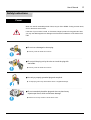
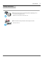
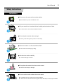
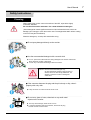
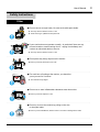
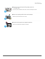
SAMTRON 76E/76V/56B
User’s Manual
Site Map
Automatic
Manual
2
User’s Manual
Safety Instructions
Warning / Caution
Failure to follow directions noted by this symbol could result in bodily harm or damage to
equipment.
Notational Conventions
Prohibited
Important to read and understand at all times
Do not disassemble
Disconnect the plug from the outlet
Do not touch
Grounding to prevent an electric shock
3
User’s Manual
4
Safety Instructions
Power
When not used for extended periods of time, set your PC to DPMS. If using a screen saver,
set it to the active screen mode.
If the size of your monitor is small, or if the same image is present for long periods of time,
you may see afterimages due to damage to the flourescent substance on the inside of the
CDT.
● Do not use a damaged or loose plug.
◆ This may cause an electric shock or fire.
● Do not pull the plug out by the wire nor touch the plug with
wet hands.
◆ This may cause an electric shock or fire.
● Use only a properly grounded plug and recepticle.
◆ An improper ground may cause electric shock or equipment damage.
● Do not excessively bend the plug and wire nor place heavy
objects upon them, which could cause damage.
◆ Failure to do so may cause an electric shock or fire.
User’s Manual
Safety Instructions
● Disconnect the plug from the outlet during storms or lightening or if it is
not used for a long period of time.
◆ Failure to do so may cause an electric shock or fire.
● Do not connect too many extension cords or plugs to an outlet.
◆ This may cause a fire.
5
User’s Manual
6
Safety Instructions
Installation
● Do not cover the vents on the monitor cabinet.
◆ Bad ventilation may cause a breakdown or fire.
● Put your monitor in a location with low humidity and a minimum of dust.
◆ An electric short or fire could result inside the monitor.
● Do not drop the monitor when moving it.
◆ This may cause damage to the product or human body.
● Place the monitor on a flat and stable surface.
◆ The monitor can cause injury by falling.
● Set down the monitor carefully.
◆ It could be damaged or broken.
● Do not place the monitor face down on the screen.
◆ The CRT surface may be damaged.
● Do not use the monitor without the monitor stand.
◆ It could break down or cause a fire due to bad ventilation.
◆ If the monitor must be used without the supplied stand, take steps to insure proper ventilation.
User’s Manual
Safety Instructions
Cleaning
When cleaning the monitor case or the surface of the CRT, wipe with a slightly
moistened, soft fabric.
Do not clean Flat monitor with water. Use a water-diluted mild detergent.
(Some detergents contain significant amounts of alcohol-based solvents, which can
damage (color change) or crack the monitor case. The antiglare/anti-static surface coating
on the CDT may also be affected.)
Dilute the detergent (1:10 ratio) with water before using.
● Do not spray detergent directly on the monitor.
● Use the recommended detergent with a smooth cloth.
◆ You can prevent the coated CRT from being damaged or the monitor cabinet from
being dissolved, cracked or discolored.
◆ You can buy a recommended detergent at Service Center.
Caution: Use a recommended detergent only,
as other surfactants containing large amounts of
alcohol, solvent or other strong substances, can
discolor or crack the monitor or damage the
coated CDT
● If the connector between the plug and the pin is dusty or dirty, clean it
properly with a dry cloth.
◆ A dirty connector can cause an electric shock or fire.
● Do not set a glass of water, chemicals or any small metal
objects on the monitor.
◆ This may cause damage, electric shock or a fire.
◆ If a foreign substance gets into the monitor, disconnect the plug
and then contact a service center.
7
User’s Manual
Safety Instructions
Other
● Do not remove cover(or back). No user serviceable parts inside.
◆ This may cause an electric shock or a fire.
◆ Refer servicing to qualified service personnel.
● If your monitor does not operate normally - in particular,if there are any
unusual sounds or smells coming from it - unplug it immediately and
contact an authorized dealer or service.
◆ This may cause an electric shock or a fire.
● Do not place any heavy objects on the monitor.
◆ This may cause an electric shock or a fire.
● For each hour of looking at the monitor, you should let
your eyes rest for 5 minutes.
◆ This will reduce eye fatigue.
● Do not use or store inflammable substances near the monitor.
◆ This may cause an explosion or fire.
● Do not try to move the monitor by pulling on the wire
or the signal cable.
◆ This may cause a breakdown, electric shock or a fire due to damage to the cable.
8
User’s Manual
● Do not move the monitor right or left by pulling only the wire
or the signal cable.
◆ This may cause a breakdown, electric shock or a fire due to damage to the cable.
● Never insert anything metallic into the monitor openings.
◆ This may cause an electric shock, fire or injury.
● Keep the monitor away from any magnetic substances..
◆ This may cause discoloring or distortion of the image.
9
User’s Manual
Introduction
Unpacking
■ Monitor and Stand
■ Power Cord
■ Stand
■ Quick Setup Guide
(Your monitor is shipped with the base detached.)
Please make sure the following items are included with
your monitor. If any items are missing, contact your dealer.
■ Warranty card (Not available in all locations)
■ User's Guide and Driver Installation CD
10
User’s Manual
11
Introduction
Front
1.
2,3.
4.
5.
6.
Note:
Exit button
Adjust buttons
Menu button
Power indicator
Power button
: Use this button to Exit the active menu or the OSD.
: These buttons allow you to highlight and adjust items in the menu.
: Use this button to open the OSD and activate a highlighted menu item.
: Indicates normal or Power Saving Mode.
: Use this button to turn the monitor on and off.
See PowerSaver described in the manual for further information regarding power saving functions.
For energy conversation,turn your monitor OFF when it is not needed,or when leaving it unattended for
long periods.
User’s Manual
12
Introduction
Rear
1. Power port : Connect the power cord for your
monitor to the power port on the back
of the monitor.
2.Signal cable :Connect the end of the signal cable
to your computer's video port
(video board,video card or graphics
card).
Note: See Connecting Your Monitor for further information
regarding cable connections.
(The configuration at the back of the moniter
may vary from product to product.)
Bottom
1. Signal cable : Connect the end of the signal cable to your computer's video port(video board,
video card or graphics card).
2. Power port : Connect the power cord for your monitor to the power port on the back of the monitor.
3. Tilt/Swivel Base : You can separate the base from the monitor.
User’s Manual
Setup
Connecting Your Monitor
1.Connect the power cord for your monitor to the power port on the back of the monitor.
Plug the power cord for the monitor into a nearby outlet.
2.Connect the end of the signal cable to your computer's video port(video board,
video card or graphics card).
3.If you are using a Macintosh computer, connect the cable to a Macintosh adapter,
and set the pins on your adapter(Adapter not included). A PC-compatible computer does not
need an adapter.
Note: Turn on your computer and monitor. If your monitor displays an image, installation is complete.
13
User’s Manual
Setup
Installing the Video Driver
When prompted by the operating system for the monitor driver, insert the CD-ROM
included with this monitor. Driver installation is slightly different from one operating sys
tem to another. Follow the directions as appropriate for the operating system you have.
Prepare a blank disk and download the driver program file at the Internet web site shown here.
Internet web site : http://www.samtron.com/
Windows ME/98/95
1. Insert CD into the CD-ROM driver.
2. Click "Windows ME/98/95 Driver".
3. Choose your monitor model in the model list, then click the "OK" button.
4. Click the "Install" button in the "Warning" window.
5. Monitor Driver installation is completed.
14
User’s Manual
Setup
Installing the Video Driver
Windows XP/2000
1. Insert CD into the CD-ROM driver.
2. Click "Windows XP/2000 Driver".
3. Choose your monitor model in the model list, then click the "OK" button.
4. Click the "Install" button in the "Warning" window.
5. If you can see following "Message" window, then click the "Continue Anyway" button.
Then click "OK" button.
15
User’s Manual
16
Setup
Installing the Video Driver
This monitor driver is under certifying MS logo, and this installation don't damage your system. The certifide
driver will be posted on Samtron Monitor Homepage.
http://www.samtron.com/
6. Monitor Driver installation is completed.
User’s Manual
Setup
Installing the Video Driver
When prompted by the operating system for the monitor driver, insert the CD-ROM
included with this monitor. Driver installation is slightly different from one operating sys
tem to another. Follow the directions as appropriate for the operating system you have.
Prepare a blank disk and download the driver program file at the Internet web site shown here.
Internet web site : http://www.samtron.com/
Microsoft® Windows® XP Operating System
1. Insert CD into the CD-ROM driver.
2. Click "Start" —> "Control Panel" then click the "Appearance and Themes" Icon.
3. Click "Display" icon and choose the "Settings" tab then click "Advanced..".
17
User’s Manual
Setup
Installing the Video Driver
4. Click the "Properties" button on the "Monitor" tab and select "Driver" tab.
5. Click "Update Driver.." and select "Install from a list or.." then click "Next" button.
6. Select "Don't search ,I will.." then click "Next" and then click "Have disk".
18
User’s Manual
Setup
Installing the Video Driver
7. Click the "Browse" button then choose A:(D:\Driver) and choose your monitor model in the model list and
click the "Next" button.
8. If you can see following "Message" window, then click the "Continue Anyway" button. Then click "OK"
button.
This monitor driver is under certifying MS logo,and this installation don't damage your system.The certified
driver will be posted on Samtron
Monitor Homepage.
.
http://www.samtron.com/
9. Click the "Close" button then click "OK" button continually.
19
User’s Manual
20
Setup
Installing the Video Driver
10. Monitor driver installation is completed.
Microsoft® Windows® 2000 Operating System
When you can see "Digital Signature Not Found" on your monitor, follow these steps.
1. Choose "OK" button on the "Insert disk" window.
2. Click the "Browse" button on the "File Needed" window.
3. Choose A:(D:\Driver) then click the "Open" button and then click "OK" button.
How to install
1.
2.
3.
4.
5.
6.
7.
8.
9.
10.
Click "Start" , "Setting" , "Control Panel".
Double click the "Display" Icon.
Choose the "Settings" tab and then click "Advanced..".
Choose "Monitor".
Case1: If the "Properties" button is inactive, it means your monitor is properly configured. Please stop
installation
Case2: If the "Properties" button is active, click the "Properties" button then follow next steps continually.
Click "Driver" and then click on "Update Driver.." then click on the "Next" button.
Choose "Display a list of the known drivers for this device so that I can choose a specific driver" then
click "Next" and then click "Have disk".
Click the "Browse" button then choose A:(D:\Driver).
Click the "Open" button, then click "OK" button.
Choose your monitor model and click the "Next" button then click "Next" button.
Click the "Finish" button then the "Close" button.
If you can see the "Digital Signature Not Found" window then click the "Yes"button. And click the
"Finish" button then the "Close" button.
User’s Manual
21
Setup
Installing the Video Driver
Microsoft® Windows® Millennium Operating System
1.
2.
3.
4.
5.
6.
7.
8.
9.
10.
Click "Start" , "Setting" , "Control Panel".
Double click "Display" icon.
Select the "Settings" tab and click "Advanced Properties" button.
Select the "Monitor" tab.
Click the "Change" button in the "Monitor Type" area.
Choose "Specify the location of the driver".
Choose "Display a list of all the driver in a specific location.." then click "Next" button.
Click the "Have Disk" button
Specify A:\(D:\driver) then click "OK" button.
Select "Show all devices" and choose the monitor that corresponds to the one you connected to your
computer and click "OK".
11. Continue choosing "Close" button and "OK" button until you close the Display Properties dialogue box.
(You can get some other screen for warning message or others, then click the appreciate option for your
monitor.)
Microsoft® Windows® 98 Operating System
1.
2.
3.
4.
5.
6.
7.
8.
9.
Click "Start" , "Setting" , "Control Panel".
Double click "Display" icon.
Select the "Settings" tab and click "Advanced Properties" button.
Select the "Monitor" tab.
Click the "Change" button in the "Monitor Type" area then click "Next" button.
Choose "Display a list of all the driver.." then click "Next" button.
Click the "Have Disk" button, then click "browse.." button.
Specify A:\(D:\driver) then click "OK" button.
The "Select Device" dialogue box will appear. Select "Show all devices" then choose the monitor that
corresponds to the one you connected to your computer and click OK.
10. Continue choosing "Close" button and "O.K" button until you close the Display Properties dialogue box.
Microsoft® Windows® 95 Operating System
First determine the Windows 95 version installed on your computer by right-clicking the My Computer icon on PC
and selecting Properties. The version number is listed under System. Perform the steps for the appropriate version.
Version 4.00.950A
1.
2.
3.
4.
5.
6.
Click Start, Settings, Control Panel, and then double-click "Display" icon.
In the "Display Properties" window, click the "Settings" tab and click "Change Display Type".
In the "Change Display Type" window, click "Change" and then click "Have Disk".
Click "browse.." button and specify A:\(D:\driver) and click "OK".
In the Select Device window, click the appropriate monitor model and then click OK.
Continue choosing "Close" button and "OK" button until you close the "Display Properties" dialogue box.
User’s Manual
22
Setup
Installing the Video Driver
Version 4.00.950B
1.
2.
3.
4.
5.
6.
7.
Click Start, Settings, Control Panel, and then double-click "Display" icon.
In the "Display Properties" window, click the Settings tab and then click "Advanced Properties" button.
In the "Advanced Display Properties" window, click the "Monitor" tab and then click "Change" button.
In the "Select Device" window, click "Have Disk" button.
Click "browse.." button and specify A:\(D:\driver) and click "OK".
In the "Select Device" window, click the appropriate monitor model and then click "OK".
Continue choosing "Close" button and "OK" button until you close the "Display Properties" dialogue box.
Microsoft® Windows® NT Operating System
1.
2.
3.
4.
Click Start, Settings, Control Panel, and then double-click Display icon.
In Display Registration Information window, click Settings Tab and then click All Display Modes.
Select a mode that you wish to use (Resolution, Number of colors and Vertical frequency) and then click OK.
Click Apply button if you see the screen working normally after clicking Test. If the screen is not normal,
change to a different mode (lower mode of resolution, colors or frequency).
Note: If there is no Mode at All Display Modes, select the level of resolution and vertical frequency by referring
to the Preset Display Modes
Linux Operating System
To execute X-Window, you need to make the X86Config file, which is a type of system setting file.
1.
2.
3.
4.
5.
6.
7.
8.
9.
10.
Press Enter at the first and the second screen after executing the X86Config file.
The third screen is for setting your mouse.
Set a mouse for your computer.
The next screen is for selecting a keyboard.
Set a Keyboard for your computer.
The next screen is for setting your monitor.
First of all, set a horizontal frequency for your monitor. (You can enter the frequency directly.)
Set a vertical frequency for your monitor. (You can enter the frequency directly.)
Enter the model name of your monitor. This information will not affect the actual execution of X-Window.
You have finished setting up your monitor.
Execute X-Window after setting other requested hardware.
User’s Manual
Setup
Tilt/Swivel Base Installation
1. Tilt/Swivel Base
With the built-in pedestal, you can tilt and/or swivel the monitor for the most comfortable
viewing angle.
Note: The base is detachable. Your monitor is shipped with the base detached.
23
User’s Manual
Setup
2. Attaching the Base
If your monitor was supplied with the base detached, attach the base as follows.
Remove the twist-tie before attaching the base to the monitor.
1. Place the monitor upside-down on a flat
work surface.
2. Align the tabs on the base with the corresponding
slots on the bottom of the monitor.
Do not bend the snap.
3. Press the base onto the monitor until the tabs
are fully engaged in the slots.
4. Push the base toward the front of the monitor
until the release latch clicks into the locked position.
Note: The Base will align with the monitor slots in only one position.
24
User’s Manual
Setup
3. Removing the Base
1.
Turn off the monitor and unplug it from the electrical outlet.
2.
Place the monitor upside down on a stable, flat work surface.
3.
Squeeze and pull up on the release latch on the base.
4.
Push the base toward the back of the monitor and lift
up to remove the base.
25
User’s Manual
On Screen Display (OSD) Menu System
1
Use this button to open the OSD and activate
a highlighted menu item.
2.3 Use these buttons to highlight and adjust items using
the On-Screen Display. These buttons are also direct
access buttons for the contrast and brightness feature.
4
Use this button to Exit the active menu or the OSD.
26
User’s Manual
On Screen Display (OSD) Menu System
Menu
How to adjust
Brightness
: Background brightness of screen.
– Decreases brightness
+ Increases brightness
Contrast
: Contrast of screen image.
– Decreases contrast
+ Increases contrast
Horizontal Position
: Horizontal screen position.
– Moves screen left
+ Moves screen right
Vertical Position
: Vertical screen position.
– Moves screen down
+ Moves screen up
Horizontal Size
: Horizontal screen size.
– Decreases size
+ Increases size
27
User’s Manual
On Screen Display (OSD) Menu System
Menu
How to adjust
Vertical Size
: Vertical screen size.
– Decreases size
+ Increases size
Pincushion
: Straightens screen vertical edges.
– Curves image inward
+ Curves image outward
Geometry
: Adjust the Trapezoid, Parallelogram, Rotation,
Pinbalance, V-Linearity of the screen image.
Trapezoid
: Width of top and bottom of screen.
– Widens bottom of screen
+ Widens top of screen
Parallelogram
– Skews screen image left
+ Skews screen image right
28
User’s Manual
On Screen Display (OSD) Menu System
Menu
How to adjust
Rotation
– Rotates entire screen left
+ Rotates entire screen right
Pinbalance
– Curves vertical lines to left
+ Curves vertical lines to right
V-Linearity
– Compresses image at top of screen
+ Compresses image at bottom of screen
Language
: – and + scroll through on-screen language options.
(English/ Deutsch/ Francais/ Italiano/Português/
Español/ Svenska/ Russian/Korean)
Note: The language chosen affects only the language of the OSD. It has no effect on any
software running on the computer.
29
User’s Manual
On Screen Display (OSD) Menu System
Menu
How to adjust
Advanced
H-Moire
: Corrects for on-screen moiré pattern.
– and + clear horizontal moiré
V-Moire
: Corrects for on-screen moiré pattern.
– and + clear vertical moiré
Video Input Level
: Selects the video signal level.
– Select 0.7 V
+ Select 1.0 V
30
User’s Manual
On Screen Display (OSD) Menu System
Menu
How to adjust
Color Temperature
– 9300k more blue
+ 6500k more red
Zoom
– Reduces view of display area
+ Enlarges view of display area
Degauss
: Removes color distortion caused by magnetic fields.
Do not use more than once in 30 minutes.
Recall
: Returns monitor to original settings.
- No
+ Yes
31
User’s Manual
On Screen Display (OSD) Menu System
Menu
How to adjust
Display Timing
: Monitor display settings.
– Factory timing
+ User timing
OSD Lock/Unlock
: Allows you to secure the current control settings so
that they cannot be inadvertently changed.
You can unlock the OSD controls at any time by
using the same procedure.
Push and hold in the Menu button for 10 seconds
or more to Lock or to Unlock.
32
User’s Manual
Troubleshooting
Chek List
Note :
Before calling for service, check the information in this section to see if you can solve the problem yourself.
If you do need assistance, please call the phone number on the warranty card, the phone number on
the Information section or contact your dealer.
Symptom
No Images on the
screen.
I cannot trun on the
monitor.
Chek List
Solution
Is the power cord connected
properly?
Check the power cord connection and
supply.
Can you see "No Connection, Check
Signal Cable" on the screen?
Check the signal cable connection.
If the power is on, reboot the
computer to see the initial
screen(the login screen),
which can be seen.
If the initial screen (the login screen)
appears, boot the computer in the
applicable mode (the safe mode for
Windows 98/95) and then change the
frequency of the video card.(Refer to
the Preset Display Modes)
Note: If the initial screen (the login
screen) does not appear,
contact a service center or
your dealer.
Can you see "Sync. Out of Range"
on the screen?
You can see this message when the
signal from the video card exceeds the
maximum resolution and frequency that
the monitor can properly handle.
Adjust the maximum resolution and
frequency applicable to the monitor.
There is no image on the screen.Is
the power indicator on the monitor
blinking at 1 second intervals?
I cannot see the On
Screen
Display(OSD).
Have you locked the On Screen
Display (OSD) Menu to prevent
changes?
The monitor is in PowerSave mode.
Press a key on the keyboard or move
the mouse to activate the monitor and
restore the image on the screen.
Unlock the OSD by pressing the MENU
button for at least 10 seconds.
33
User’s Manual
Troubleshooting
Symptom
The image on the screen
is shaking.
Chek List
Solution
Check the monitor configuration to
see if it is in Interlace Mode.
(Interlace Mode: Vertical frequency
43Hz, 87Hz(i), etc)
The signal from the video card
exceeds the maximum resolution
and frequency of the monitor.
Are there any magnetic products
such as a high voltage wire near by?
Move the monitor away from
anything that can create a strong
magnetic field.
Is the voltage stable?
The screen image can appear to
shake or vibrate at a particular time
of day due to low supply voltage.
The screen image can also appear to shake or vibrate if there is a problem with the video
card or the computer's main board.
The screen shows
strange colors or
just black and
white.
Is the screen displaying only one
color as if looking at the screen
through a cellophane paper?
Check the signal cable connection.
Have the screen colors become
strange after running a program or due
to a crash between applications?
Reboot the computer.
Has the video card been set properly?
Set the video card by referring to the
video card manual.
The screen suddenly has Have you changed the video card or
become
the driver?
unbalanced.
Have you adjusted the resolution or
frequency to the monitor?
Make sure the video card is fully
inserted in it's slot.
Adjust screen image position and
size using the OSD.
Adjust the resolution and frequency
at the video card.
(Refer to the Preset Display Modes)
The screen can be unbalanced due to the cycle of the video card signals.
Readjust Position by referring to the OSD.
The screen is out of
focus or OSD
cannot be adjusted.
Have you adjusted the resolution or
frequency on the monitor?
Adjust the resolution and frequency of
the video card.
(Refer to the Preset Display Modes)
34
User’s Manual
Troubleshooting
Symptom
The screen is
partialy distorted.
LED is blinking but
no images on the
screen.
Chek List
Are there any magnetic products such
as an adapter, speaker or a high
voltage wire near the monitor?
Is the frequency properly adjusted
when checking the Display Timing
on the menu?
Solution
Enter the OSD and perform a
'Degauss'.
Keep the monitor away from any
magnetic products.
Adjust the frequency properly by
referring to the video card manual
and the Preset Display Modes.
(The maximum frequency per
resolution may differ from product to
product.)
There are only 16
colors shown on the
screen. The screen
colors have changed
after changing the video
card.
There is a message
that reads
“Unrecognized
monitor, Plug & Play
(VESA DDC)
monitor found”.
Have the Windows colors been set
properly?
For Windows 98(95):
Set the colors properly at the Control
Panel, Display, Settings.
For Windows 3.1:
Adjust the colors of the screen using
the VGA utility provided by the video
card.
Has the video card been set
properly?
Set the video card by referring to the
video card manual.
Have you installed the monitor
driver?
Install the monitor driver according to
the Driver Installation Instructions.
See the video card manual to see if
the Plug & Play (VESA DDC)
function can be supported.
Install the monitor driver according to
the Driver Installation Instructions.
35
User’s Manual
Troubleshooting
Check the following items if there is trouble with the monitor.
1. Check if the power cord and the cable are properly connected to the computer.
2. Check if the computer beeps more than 3 times when booting.
(If it does, request an after-service for the main board of the computer.)
3. If you installed a new video card or if you assembled the PC, check if the installed the adapter
(video) driver and the monitor driver.
4. Check if the scanning ratio of the video screen is set at 75Hz or 85Hz.
(Do not exceed 60Hz when using the maximum resolution.)
5. If you have problems in installing the adapter (video) driver, boot the computer in Safe Mode,
remove the Display Adapter at "the Control Panel, System, Device Administrator" and then
reboot the computer to reinstall the adapter (video) driver.
Note:If problems repeatedly occur, contact an authorized service center.
36
User’s Manual
37
Troubleshooting
Q&A
Question
How can I change the
frequency?
Answer
Frequency can be changed by reconfiguring the video card.
Note that video card support can vary, depending on the version of the
driver used.
(Refer to the computer or the video card manual fordetails.)
How can I adjust the resolution?
Windows 95/98: Set the resolution at the Control Panel,
Display, Settings.
Windows 3.1: Change the resolution and the colors
using the VGA Utility provided by the video card.
* Contact the video card manufacturer for details.
How can I set the Power
Saving function?
Windows 95/98: Set the function at BIOS-SETUP of the computer or the
screen saver. (Refer to Windows/Computer Manual)
Windows 3.1: Set the function using the VGA Utility
provided by the video card.
The monitor makes a sound when it
is turned on.
This is normal as some sound may be generated when the metal case and
the electromagnet, which are installed to block any electromagnetic waves,
interact with each other.
How can I clean the outer
case/Picture tube?
Disconnect the power cord and then clean the monitor with a soft cloth,
using either a plain water.
Do not leave any remains of the detergent nor scratch the case. Do not
allow any water to go inside the monitor.
User’s Manual
Troubleshooting
Self-Test Feature Check
A self-test feature is provided that allows you to check for proper monitor function. If your monitor and
computer are properly connected but the monitor screen remains dark and the power indicator is blinking, run
the monitor self-test by performing the following steps:
Self-Test Feature Check
1. Turn off both your computer and the monitor.
2. Unplug the video cable from the back of the computer.
3. Turn on the monitor.
If your monitor is functioning properly, you will see a box with a red border and blue text inside
as shown in the following illustration:
The three boxes inside the border are red, green and blue.
Failure of any of the boxes to appear indicates a problem with your monitor. This box also
appears during normal operation if the video cable becomes disconnected or damaged.
4.Turn off your monitor and reconnect the video cable; then turn on both your
computer and the monitor.
If your monitor screen remains blank after using the previous procedure, check your video
controller and computer system; your monitor is functioning properly.
38
User’s Manual
39
Troubleshooting
Self-Test Feature Check
Warning Messages
If there is something wrong with the input signal, a message appears on the screen or the screen goes blank
although the power indicator LED is still on. The message may indicate that the monitor is out of scan range or that
you need to check the signal cable.
Environment
The location and the position of the monitor may influence the quality and other features of the monitor.
1. If there are any woofer speakers near the monitor, unplug and relocate the
woofer to another room.
2. Remove all electronic devices such as radios, fans, clocks and telephones that
are within 3 feet (one meter) of the monitor.
3. Degauss the monitor if any devices were removed from the area.
Userful Tip
A monitor recreates visual signals received from the PC. Therefore, if there is trouble with the PC or the video card, this can
cause the monitor to become blank, have poor coloring, noise, Sync. Out of Range, etc. In this case, first check the source
of the problem, and then contact a service center or your dealer.
Judging the monitor's working condition
If there is no image on the screen or an "Sync. Out of Range" message comes up, disconnect the cable from
the computer while the monitor is still powered on.
◆ If there is a message coming up on the screen or if the screen goes white, this means the monitor is in
working condition.
◆ In this case, check the computer for trouble.
User’s Manual
Specifications
General Specifications
General
Model Name
SAMTRON 76E
Picture Tube
Type
17" (43cm) Full square type (40.6cm viewable)
Deflection angle
90°
Dot Pitch
0.23 mm(Horizontal)
Screen type
Silica coated with anti-electronic properties (TCO : Multilayer coating)
Medium-short persistence phosphor.
Maximum Resolution
1280 Dots, 1024 Lines
Active Display
Horizontal
12.3 ± 0.16 inch (312 ± 4 mm)
Vertical
9.2 ± 0.16 inch (234 ± 4 mm)
Synchronization
Horizontal
30 ~ 70 kHz
Vertical
50 ~ 160 Hz
Input Signal, Terminated
Analog
0.7 Vpp positive at 75 ohms
Separate Sync
TTL level, positive or negative
Display Color
Unlimited
Maximum Pixel Clock
110 MHz
Power Supply
AC 110 ~ 240V ± 10%, 60Hz/50 Hz ± 3Hz
Power Consumption
90W (Maximum), 75W (Nominal)
Dimensions (WxDxH)
398 x 412 x 400 mm (with base)
Weight
15.0 kg
Plug and Play Capability
This monitor can be installed on any Plug & Play compatible system. Interaction of the monitor and
computer systems will provide the best operating conditions and monitor settings. In most cases,
monitor installation will proceed automatically, unless the user wishes to select alternate settings.
40
User s Manual
Specifications
General Specifications
General
Model Name
SAMTRON 76V
Picture Tube
Type
17" (43cm) Full square type (40.6cm viewable)
Deflection angle
90°
Dot Pitch
0.23 mm(Horizontal)
Screen type
Medium-short persistence phosphor.
Maximum Resolution
1280 Dots, 1024 Lines
Active Display
Horizontal
12.3 ± 0.16 inch (312 ± 4 mm)
Vertical
9.2 ± 0.16 inch (234 ± 4 mm)
Synchronization
Horizontal
30 ~ 70 kHz
Vertical
50 ~ 160 Hz
Input Signal, Terminated
Analog
0.7 Vpp positive at 75 ohms
Separate Sync
TTL level, positive or negative
Display Color
Unlimited
Maximum Pixel Clock
110 MHz
Power Supply
AC 100 ~ 240V ± 10%, 60Hz/50 Hz ± 3Hz
Power Consumption
90W (Maximum), 75W (Nominal)
Dimensions (WxDxH)
398 x 412 x 400 mm
Weight
15.0 kg
Plug and Play Capability
This monitor can be installed on any Plug & Play compatible system. Interaction of the monitor and
computer systems will provide the best operating conditions and monitor settings. In most cases,
monitor installation will proceed automatically, unless the user wishes to select alternate settings.
41
User’s Manual
Specifications
General Specifications
General
Model Name
SAMTRON 56B
Picture Tube
Type
15" (38cm) Full square type (35cm viewable)
Deflection angle
90°
Dot Pitch
0.24 mm(Horizontal)
Screen type
Medium-short persistence phosphor.
Maximum Resolution
1280 Dots, 1024 Lines
Active Display
Horizontal
10.5 ± 0.16 inch (267 ± 4 mm)
Vertical
7.9 ± 0.16 inch (200 ± 4 mm)
Synchronization
Horizontal
30 ~ 70 kHz
Vertical
50 ~ 160 Hz
Input Signal, Terminated
Analog
0.7 Vpp positive at 75 ohms
Separate Sync
TTL level, positive or negative
Display Color
Unlimited
Maximum Pixel Clock
110 MHz
Power Supply
AC 100 ~ 240V ± 10%, 60Hz/50 Hz ± 3Hz
Power Consumption
75 W (Maximun), 65W (Nominal)
Dimensions (WxDxH)
356 x 379 x 369.5 mm (with Base)
Weight
11.5 kg
Plug and Play Capability
This monitor can be installed on any Plug & Play compatible system. Interaction of the monitor and
computer systems will provide the best operating conditions and monitor settings. In most cases,
monitor installation will proceed automatically, unless the user wishes to select alternate settings.
42
User’s Manual
43
Specifications
Preset Display Modes
If the signal transferred from the computer is the same as the following Preset Display Modes, the
screen will be adjusted automatically. However, if the signal differs, the screen may go blank while
the power LED is on. Refer to the video card manual and adjust the screen as follows.
Display Mode
Horizontal Frequency
(kHz)
Vertical Frequency
(Hz)
Pixel Clock
(MHz)
Sync Polarity
(H/V)
IBM, 640 x 480
31.469
59.940
25.175
-/-
IBM, 720 x 400
31.469
70.087
28.322
-/+
VESA, 640 X 480
37.500
75.000
31.500
-/-
VESA, 640 X 480
43.269
85.008
36.000
-/-
VESA, 800 X 600
46.875
75.000
49.500
+/+
VESA, 800 X 600
53.674
85.061
56.250
+/+
VESA, 1024 X 768
60.023
75.029
78.750
+/+
VESA, 1024 X 768
68.677
84.997
94.500
+/+
Horizontal Frequency
The time to scan one line connecting the right edge to the left edge of the screen
horizontally is called Horizontal Cycle and the inverse number of the Horizontal
Cycle is called Horizontal Frequency.
Unit: kHz
Vertical Frequency
Like a fluorescent lamp, the screen has to repeat the same image many times per
second to display an image to the user. The frequency of this repetition is called
Vertical Frequency or Refresh Rate.
Unit: Hz
User’s Manual
44
Specifications
PowerSaver
This monitor has a built-in power management system called PowerSaver. This system saves energy
by switching your monitor into a low-power mode when it has not been used for a certain amount of
time. The monitor automatically returns to normal operation when you move the computer's mouse or
press a key on the keyboard. For energy conservation, turn your monitor OFF when it is not needed, or
when leaving it unattended for long periods. The PowerSaver system operates with a VESA DPMS
compliant video card installed in your computer. Use a software utility installed on your computer to
set up this feature.
SAMTRON 76E / 76V
State
Normal Operation
Power Indicator
Green
Power
75W(Nominal)
Consumption
90W(Maximum)
Power-off Mode EPA/ENERGY 2000
Green, Blinking (1 sec. interval)
Less than 3W
SAMTRON 56B
State
Normal Operation
Power Indicator
Green
Power
65W(Nominal)
Consumption
75W(Maximum)
Power-off Mode EPA/ENERGY 2000
Green, Blinking (1 sec. interval)
Less than 3W
This monitor is EPA ENERGY STAR R compliant and ENERGY2000 compliant
when used with a computer equipped with VESA DPMS functionality.
As an ENERGY STAR R Partner, SAMSUNG has determined that this product
meets the ENERGY STAR R guidelines for energy efficiency.
User’s Manual
Information
Service
● SAMTRON SEOUL
15TH FL, JOONGANG DAILY NEWS BLDG. 7, SOONHWA-DONG,CHUNG-KU,
SEOUL, KOREA, 100-759
TEL : (82-2) 727-3114
● SAMTRON U.S.A
SAMTRON COMPUTER PRODUCTS CUSTOMER SERVICE
400 Valley Road Suite 201, Mt. Arlington, NJ 07856
TEL : 973-601-6200, FAX : 973-601-6001
1-800-SAMTRON (1-800-726-8766)
● SAMTRON CANADA
SAMSUNG ELECTRONICS CANADA INC.
7037 FINANCIAL DRIVE
MISSISSAUGA, ONTARIO L5N 6R3
TEL : 1-800-726-7864
FAX : 905-542-1199
● SAMTRON EUROPE
SAMSUNG ELECTRONICS GMBH
SAMSUNG-HAUS, AM KRONBERGER HANG 6
65824 SCHWALBACH/TS., GERMANY
TEL : 49 (0180) 5121213*
FAX : 49 (0180) 5121214*
*DM 0,24/MIN
● SAMTRON TOKYO
17TH, HAMACHO CENTER BLDG. 2-31-1, NIHONBASHI-HAMACHO,
CHOU-KU, TOKYO 103, JAPAN
TEL : (81-3) 5641-9860 FAX : (81-3) 5641-9861
● SAMTRON SWEDEN
SAMSUNG ELECTRONICS SYENSKA, AB
BOX 713, S- 194 27 UPPLANDS VASBY
TEL : 468- 590- 966- 00 FAX : 468- 590- 966- 50
● SAMTRON MEXICO
SAMSUNG ELECTRONICS MEXICO, S.A. DE C. V. Mina No. 200,
ESQ. GAVILANCOL. GUADALUPE DEL MORAL IZTAPALAPA,
MEXICO, D.F. C.P. 09300
TEL. : (525) 686-0800
FAX : (525) 686-5094
IMPORTADO POR : SAMSUNG ELECTRONICS MEXICO S.A. DE C.V.
SATURNO 44 COL. NVA. INDUSTRIAL VALLEJO
DEL. GUSTAVO A. MADERO C.P. 07700
MEXICO D.F. TEL. 5747-5100
RFC: SEM950215S98
EXPORTADO POR: SAMSUNG ELECTRONICS CO.,LTD.
JOONG-ANG DAILY NEWS BLDG.
7 SOON-WHA-DONG CHUNG-KU,
C.P.O BOX 2775, 1144 SEOUL, KOREA
45
User’s Manual
Information
Terms
● Dot Pitch
The image on a monitor is composed of red, green and blue dots. The closer the dots,
the higher the resolution. The distance between two dots of the same color is
called the 'Dot Pitch'. Unit: mm
● Vertical Frequency
The screen must be redrawn several times per second in order to create and display
an image for the user. The frequency of this repetition per second is called Vertical Frequency or
Refresh Rate. Unit: Hz
Example:
If the same light repeats itself 60 times per second, this is regarded as 60 Hz.
In this case, flickering of the screen can be detected. To avoid this problem,
there is a Flicker-free Mode using a vertical frequency over 70 Hz.
● Horizontal Frequency
The time to scan one line connecting the right edge to the left edge of the screen
horizontally is called Horizontal Cycle. The inverse number of the Horizontal Cycle
is called Horizontal Frequency. Unit: KHz
● Interlace and Non-Interlace Methods
Showing the horizontal lines of the screen from the top to the bottom in order is called
the Non-Interlace method while showing odd lines and then even lines in turn is
called the Interlace method. The Non-Interlace method is used for the majority of monitors to
ensure a clear image. The Interlace method is the same as that used in TVs.
● Plug & Play
This is a function that provides the best quality screen for the user by allowing
the computer and the monitor to exchange information automatically. This monitor
follows the international standard VESA DDC for the Plug & Play function.
● Resolution
The number of horizontal and vertical dots used to compose the screen image is called 'resolution'.
This number shows the accuracy of the display. High resolution is good for performing multiple tasks
as more image information can be shown on the screen.
Example: If the resolution is 1024 X 768, this means the screen is composed of
1024 horizontal dots (horizontal resolution) and 768 vertical lines
(vertical resolution).
46
User’s Manual
47
Information
Regulatory
FCC Information | IC Compliance Notice | MPR II Compliance |
European Notice (Europe only) | PCT Notice |
TCO'95-Ecological requirements for personal computers (TCO applied model only) |
TCO'99-Ecological requirements for personal computers (TCO applied model only)
● FCC Information
User Instructions
The Federal Communications Commission Radio Frequency Interference Statement includes the following
warning:
Note:
This equipment has been tested and found to comply with the limits for a Class B digital device,
pursuant to Part 15 of the FCC Rules. These limits are designed to provide reasonable protection
against harmful interference in a residential installation. This equipment generates, uses, and
can radiate radio frequency energy and, if not installed and used in accordance with the instructions,
may cause harmful interference to radio communications. However, there is no guarantee
that interference will not occur in a particular installation. If this equipment does cause harmful
interference to radio or television receptions, which can be determined by turning the equipment
off and on, the user is encouraged to try to correct the interference by one or more of
the following measures:
• Reorient or relocate the receiving antenna.
• Increase the separation between the equipment and receiver.
• Connect the equipment into an outlet on a circuit different from that to which the receiver is connected.
• Consult the dealer or an experienced radio/TV technician for help.
User Information
Changes or modifications not expressly approved by the party responsible for compliance could void
the user's authority to operate the equipment. If necessary, consult your dealer or an experienced
radio/television technician for additional suggestions. You may find the booklet called How to Identify and
Resolve Radio/TV Interference Problems helpful. This booklet was prepared by the Federal
Communications Commission. It is available from the U.S. Government Printing Office, Washington,
DC 20402, Stock Number 004-000-00345-4.
Warning
User must use shielded signal interface cables to maintain FCC compliance for the product.
Declaration of conformity for products Marked with FCC Logo
This device complies with Part 15 of the FCC Rules.Operation is subject to the following two conditions: (1)
this device may not cause harmful interference, and (2) this device must accept any interference
received, including interference that may cause undesired operation.
The party responsible for product compliance:
SAMSUNG ELECTRONICS CO., LTD
America QA Lab of Samsung
85 West Tasman Drive
San Jose, CA 95134 USA
Tel) 408-544-5124
Fax) 408-544-5191
User’s Manual
48
Information
Provided with this monitor is a detachable power supply cord with IEC320 style terminations. It may be suitable for
connection to any UL Listed personal computer with similar configuration. Before making the connection, make
sure the voltage rating of the computer convenience outlet is the same as the monitor and that the ampere rating of
the computer convenience outlet is equal to or exceeds the monitor voltage rating.
For 120 Volt applications, use only UL Listed detachable power cord with NEMA configuration 5-15P type (parallel
blades) plug cap. For 240 Volt applications use only UL Listed Detachable power supply cord with NEMA
configuration 6-15P type (tandem blades) plug cap.
● IC Compliance Notice
This Class B digital apparatus meets all requirements of the Canadian Interference-Causing Equipment
Regulations of ICES-003.
Cet appareil Numérique de classe B respecte toutes les exigences du Règlemont ICES-003 sur les
équipements produisant des interférences au Canada.
● MPR II Compliance
This monitor complies with SWEDAC(MPR II) recommendations for reduced electric and magnetic fields.
● European Notice (Europe only)
Products with the CE Marking comply with both the EMC Directive (89/336/EEC), (92/31/EEC), (93/68/EEC)
and the Low Voltage Directive (73/23/EEC) issued by the Commission of the European Community.
Compliance with these directives implies conformity to the following European Norms:
• EN55022:1998 - Radio Frequency Interference
• EN55024:1998 - Electromagnetic Immunity
• EN61000-3-2:1995+A1+A2 - Power Line Harmonics
• EN61000-3-3:1995 - Voltage Fluctuations
• EN60950 - Product Safety.
● PCT Notice
User’s Manual
49
Information
● TCO'95-Ecological requirements for personal computers (TCO applied model only)
AB general requirements
AB2 Written Eco-document acompanying the products
Congratulations! You have just purchased a TCO'95 approved and labelled product! Your choice has provided you with a product
developed for professional use. Your purchase has also contributed to reducing the burden on the environment and to the further
development of environmentally- adapted electronic products.
Why do we have environmentally-labelled monitors?
In many countries, environmental labelling has become an established method for encouraging the adaptation of goods and services to
the environment.The main problem as far as monitors and other electronic equipment are concerned is that environmentally harmful
substances are used both in the products and during their manufacture. Since it has not been possible so far for the majority of
electronic equipment to be recycled in a satisfactory way, most of these potentially damaging substances sooner or later enter Nature.
There are also other characteristics of a monitor, such as energy consumption levels, that are important from both the working and
natural environment viewpoints.Since all types of conventional electricity generation have a negative effect on the environment (acidic
and climate-influencing emissions, radioactive waste, etc.) it is vital to conserve energy. Electronic equipment in offices consumes an
enormous amount of energy, since it is often routinely left running continuously.
What does labelling involve?
This product meets the requirements for the TCO'95 scheme, which provides for international environmental labelling of monitors.
The labelling scheme was developed as a joint effort by the TCO (The Swedish Confederation of Professional Employees),
Naturskyddsforeningen (The Swedish Society for Nature Conservation) and NUTEK (The National Board for Industrial and Technical
Development in Sweden).
The requirements cover a wide range of issues: environment, ergonomics, usability, emission of electrical and magnetic fields, energy
consumption and electrical and fire safety.
The environmental demands concern among other things restrictions on the presence and use of heavy metals, brominated and
chlorinated flame retardants, CFCs (freons), and chlorinated solvents. The product must be prepared for recycling and the manufacturer
is obliged to have an environmental plan, which must be adhered to in each country where the company conducts its operations policy.
The energy requirements include a demand that the monitor after a certain period of inactivity shall reduce its power consumption to a
lower level, in one or more stages. The length of time to reactivate the monitor shall be reasonable for the user.
Labelled products must meet strict environmental demands, for example in respect of the reduction of electric and magnetic fields,
along with physical and visual ergonomics and good usability.
TCO Development Unit 1996-11-29
On the page this folder you will find a brief summary of the environmental requirements met by this product.
The complere environmental criteria document may be ordered from:
TCO Development Unit
S-11494 Stockholm
Sweden
Fax: +46 8 782 92 07
E-mail (Internet): [email protected]
Current information regarding TCO'95-approved and labelled products may also
be obtained via the Internet, using the address:
http://www.tco-info.com/
TCO'95 is a co-operative project between(3 logos)
User’s Manual
50
Information
Environmental Requirements
Brominated flame retardants are present in printed circuit boards, cables, wires, casings and housings. In turn, they delay the spread of
fire. Up to thirty percent of the plastic in a computer casing can consist of flame retardant substances. These are related to another
group of environmental toxins, PCBs, which are suspected to give rise to similar harm, including reproductive damage in fish eating
birds and mammals, due to the bioaccumulative processes. Flame retardants have been found in human blood and researchers fear
that disturbances in foetus development may occur.
● TCO'95 demand requires that plastic components weighing more than 25 grams must not contain organically bound chlorine and
bromine.
Lead
Lead can be found in picture tubes, display screens, solders and capacitors. Lead damages the nervous system and in higher doses,
causes lead poisoning.
● TCO'95 requirement Permits the inclusion of lead since no replacement has yet been developed.
Cadmium
Cadmium is present in rechargeable batteries and in the colour generating layers of certain computer displays. Cadmium damages the
nervous system and is toxic in high doses.
● TCO'95 requirement states that batteries may not contain more than 25 ppm (parts per million) of cadmium.
The colour-generating layers of display screens must not contain any cadmium.
Mercury
Mercury is sometimes found in batteries, relays and switches. Mercury damages the nervous system and is toxic in high doses.
● TCO'95 requirement states that batteries may not contain more than 25 ppm (parts per million) of mercury.
It also demands that no mercury is present in any of the electrical or electronics components concerned with the display unit.
CFCs (freons)
CFCs (freons) are sometimes used for washing printed circuit boards and in the manufacturing of expanded foam for packaging. CFCs
break down ozone and thereby damage the ozone layer in the stratosphere, causing increased reception on Earth of ultraviolet light
with consequent increased risks of skin cancer (malignant melanoma).
● The relevant TCO'95 requirement: Neither CFCs nor HCFCs may be used during the manufacturing of the product or its packaging.
● TCO'99-Ecological requirements for personal computers (TCO applied model only)
Congratulations!
You have just purchased a TCO'99 approved and labelled product! Your choice has provided you with a product developed for
professional use. Your purchase has also contributed to reducing the burden on the environment and also to the further development of
environmentally adapted electronics products.
This product meets the requirements for the TCO'99 scheme which provides for an international environmental and quality labelling
labelling of personal computers. The labelling scheme was developed as a joint effort by the TCO(The Swedish Confederation of
Professional Employees), Svenska Naturskyddsforeningen(The Swedish Society for Nature Conservation), Statens
Energimyndighet(The Swedish National Energy Administration) and SEMKO AB.
User’s Manual
51
Information
The requirements cover a wide range of issuse: environment, ergonomics, usability, reduction of electric and magnetic fields, energy
consumption and electrical safet
Why do we have environmentally labelled computers?
In many countries, environmental labelling has become an established method for encouraging the adaptation of goods and services to
the environment. The main problem, as far as computers and other electronics equipment are concerned, is that environmentally
harmful substances are used both in the products and during their manufacture. Since it is not so far possible to satisfactorily recycle
the majority of electronics equipment, most of these potentially damaging substances sooner or later enter nature.
There are also other characteristics of a computer, such as energy consumption levels, that are important from the viewpoints of both
the work (internal) and natural (external) environments. Since all methods of electricity generation have a negative effect on the
environment (e.g. acidic and climate-influencing emissions, radioactive waste), it is vital to save energy. Electronics equipment in offices
is often left running continuously and thereby consumes a lot of energy.
What does labelling involve?
The environmental demands has been developed by Svenska Naturskyddsforeningen (The Swedish Society for Nature Conservation).
These demands impose restrictions on the presence and use of heavy metals, brominated and chlorinated flame retardants,
CFCs(freons)and chlorinated solvents, among other things. The product must be prepared for recycling and the manufacturer is obliged
to have an environmental policy which must be adhered to in each country where the company implements its operational policy.
The energy requirements include a demand that the computer and/or display, after a certain period of inactivity, shall reduce its power
consumption to a lower level in one or more stages. The length of time to reactivate the computer shall be reasonable for the user.
Below you will find a brief summary of the environmental requirements met by this product. The complete environmental criteria
document may be ordered from:
TCO Development
SE-114 94 Stockholm, Sweden
Fax: +46 8 782 92 07
Email (Internet): [email protected]
Current information regarding TCO'99 approved and labelled products may also be obtained via the Internet, using the address:
http://www.tco-info.com/
Environmental requirements
Flame retardants
Flame retardants are present in printed circuit boards, cables, wires, casings and housings. Their purpose is to prevent, or at least to
delay the spread of fire. Up to 30% of the plastic in a computer casing can consist of flame retardant substances. Most flame retardants
contain bromine or chloride, and those flame retardants are chemically related to another group of environmental toxins, PCBs. Both
the flame retardants containing bromine or chloride and the PCBs are suspected of giving rise to severe health effects, including
reproductive damage in fish-eating birds and mammals, due to the bio-accumulative* processes. Flame retardants have been found in
human blood and researchers fear that disturbances in foetus development may occur.
The relevant TCO'99 demand requires that plastic components weighing more than 25 grams must not contain flame retardants with
organically bound bromine or chlorine. Flame retardants are allowed in the printed circuit boards since no substitutes are available.
Cadmium**
Cadmium is present in rechargeable batteries and in the colour-generating layers of certain computer displays. Cadmium damages the
nervous system and is toxic in high doses. The relevant TCO'99 requirement states that batteries, the colour-generating layers of
display screens and the electrical or electronics components must not contain any cadmium.
Mercury**
Mercury is sometimes found in batteries, relays and switches. It damages the nervous system and is toxic in high doses. The relevant
TCO'99 requirement states that batteries may not contain any mercury. It also demands that mercury is not present in any of the
electrical or electronics components associated with the labelled unit. There is however one exception. Mercury is, for the time being,
permitted in the back light system of flat panel monitors as today there is no commercially available alternative. TCO aims on removing
this exception when a Mercury free alternative is available.
User’s Manual
52
Information
CFCs (freons)
The relevant TCO'99 requirement states that neither CFCs nor HCFCs may be used during the manufacture and assembly of the
product. CFCs (freons) are sometimes used for washing printed circuit boards. CFCs break down ozone and thereby damage the
ozone layer in the stratosphere, causing increased reception on earth of ultraviolet light with e.g. increased risks of skin cancer
(malignant melanoma) as a consequence.
Lead**
Lead can be found in picture tubes, display screens, solders and capacitors. Lead damages the nervous system and in higher doses,
causes lead poisoning. The relevant TCO'99 requirement permits the inclusion of lead since no replacement has yet been developed.
* Bio-accumulative is defined as substances which accumulate within living organisms.
** Lead, Cadmium and Mercury are heavy metals which are Bio-accumulative.
User’s Manual
53
Information
Authority
Information in this document is subject to change without notice.
© 2001 Samsung Electronics Co., Ltd. All rights reserved.
Reproduction in any manner whatsoever without the written permission of Samsung Electronics Co., Ltd. is strictly forbidden.
Samsung Electronics Co., Ltd. shall not be liable for errors contained herein or for incidental or consequential damages in connection
with the furnishing, performance, or use of this material.
The Samsung logo and Samtron are registered trademarks of Samsung Electronics Co., Ltd.; Microsoft, Windows and
Windows NT are registered trademarks of Microsoft Corporation; VESA, DPMS and DDC are registered trademarks of Video
Electronics Standard Association; the ENERGY STAR name and logo are registered trademarks of the U.S. Environmental Protection
Agency (EPA). As an ENERGY STAR Partner, Samsung Electronics Co., Ltd. has determined that this product meets the ENERGY
STAR guidelines for energy efficiency. All other product names mentioned herein may be the trademarks or registered trademarks of
their respective owners.
http://www.samtron.com