1
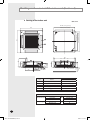
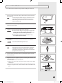
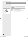
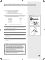
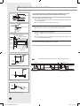
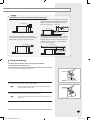
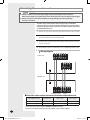
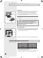
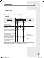
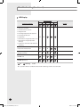
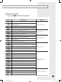
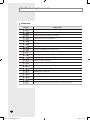
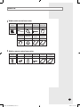
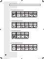
4Way_IM_DB98-26893B_E.indd 1 2009-3-7 9:39:48 Safety Precautions (Carefully follow the precautions listed below because they are essential to guarantee the safety of the equipment.) WARNING • Always disconnect the air conditioner from the power supply before servicing it or accessing its internal components. • Verify that installation and testing operations are performed by qualified personnel. • Verify that the air conditioner is not installed in an easily accessible area. GENERAL INFORMATION Carefully read the content of this manual before installing the air conditioner and store the manual in a safe place in order to be able to use it as reference after installation. For maximum safety, installers should always carefully read the following warnings. Store the operation and installation manual in a safe location and remember to hand it over to the new owner if the air conditioner is sold or transferred. This manual explains how to install an indoor unit with a split system with two SAMSUNG units. The use of other types of units with different control systems may damage the units and invalidate the warranty. The manufacturer shall not be responsible for damages arising from the use of non compliant units. The manufacturer shall not be responsible for damage originating from unauthorized changes or the improper connection of electric and requirements set forth in the “Operating limits” table, included in the manual, shall immediately invalidate the warranty. The air conditioner should be used only for the applications for which it has been designed: the indoor unit is not suitable to be installed in areas used for laundry. Do not use the units if damaged. If problems occur, switch the unit off and disconnect it from the power supply. In order to prevent electric shocks, fires or injuries, always stop the unit, disable the protection switch and contact SAMSUNG’s technical support if the unit produces smoke, if the power cable is hot or damaged or if the unit is very noisy. Always remember to inspect the unit, electric connections, refrigerant tubes and protections regularly. These operations should be performed by qualified personnel only. The unit contains moving parts, which should always be kept out of the reach of children. Do not attempt to repair, move, alter or reinstall the unit. If performed by unauthorized personnel, these operations may cause electric shocks or fires. Do not place containers with liquids or other objects on the unit. All the materials used for the manufacture and packaging of the air conditioner are recyclable. The packing material and exhaust batteries of the remote control(optional) must be disposed of in accordance with current laws. The air conditioner contains a refrigerant that has to be disposed of as special waste. At the end of its life cycle, the air conditioner must be disposed of in authorized centers or returned to the retailer so that it can be disposed of correctly and safely. INSTALLING THE UNIT IMPORTANT: When installing the unit, always remember to connect first the refrigerant tubes, then the electrical lines. Always disassemble the electric lines before the refrigerant tubes. Upon receipt, inspect the product to verify that it has not been damaged during transport. If the product appears damaged, DO NOT INSTALL it and immediately report the damage to the carrier or retailer (if the installer or the authorized technician has collected the material from the retailer.) After completing the installation, always carry out a functional test and provide the instructions on how to operate the air conditioner to the user. Do not use the air conditioner in environments with hazardous substances or close to equipment that release free flames to avoid the occurrence of fires, explosions or injuries. POWER SUPPLY LINE, FUSE OR CIRCUIT BREAKER Always make sure that the power supply is compliant with current safety standards. Always install the air conditioner in compliance with current local safety standards. Always verify that a suitable grounding connection is available. Verify that the voltage and frequency of the power supply comply with the specifications and that the installed power is sufficient to ensure the operation of any other domestic appliance connected to the same electric lines. Always verify that the cut-off and protection switches are suitably dimensioned. Verify that the air conditioner is connected to the power supply in accordance with the instructions provided in the wiring diagram included in the manual. Always verify that electric connections (cable entry, section of leads, protections…) are compliant with the electric specifications and with the instructions provided in the wiring scheme. Always verify that all connections comply with the standards applicable to the installation of air conditioners. E-2 4Way_IM_DB98-26893B_E.indd 2 2009-3-7 9:39:49 Contents Preparation for installation . . . . . . . . . . . . . . . . . . . . . . . . . . . . . . . . . . . . . . . . . . . . . . . . . . . . . . . . . . . . Deciding on where to install the indoor unit . . . . . . . . . . . . . . . . . . . . . . . . . . . . . . . . . . . . . . . . . . Indoor unit installation . . . . . . . . . . . . . . . . . . . . . . . . . . . . . . . . . . . . . . . . . . . . . . . . . . . . . . . . . . . . . . . . Purging the unit . . . . . . . . . . . . . . . . . . . . . . . . . . . . . . . . . . . . . . . . . . . . . . . . . . . . . . . . . . . . . . . . . . . . . . Connecting the refrigerant pipe . . . . . . . . . . . . . . . . . . . . . . . . . . . . . . . . . . . . . . . . . . . . . . . . . . . . . . Cutting/Flaring the pipes . . . . . . . . . . . . . . . . . . . . . . . . . . . . . . . . . . . . . . . . . . . . . . . . . . . . . . . . . . . . . Performing leak test & insulation . . . . . . . . . . . . . . . . . . . . . . . . . . . . . . . . . . . . . . . . . . . . . . . . . . . . . Drainpipe and drain hose installation . . . . . . . . . . . . . . . . . . . . . . . . . . . . . . . . . . . . . . . . . . . . . . . . . Connecting the connection cord . . . . . . . . . . . . . . . . . . . . . . . . . . . . . . . . . . . . . . . . . . . . . . . . . . . . . Assigning address to indoor unit . . . . . . . . . . . . . . . . . . . . . . . . . . . . . . . . . . . . . . . . . . . . . . . . . . . . . Installing the safety net & air blocking kits . . . . . . . . . . . . . . . . . . . . . . . . . . . . . . . . . . . . . . . . . . . . Technical Specification & Product feature . . . . . . . . . . . . . . . . . . . . . . . . . . . . . . . . . . . . . . . . . . . . . Troubleshooting . . . . . . . . . . . . . . . . . . . . . . . . . . . . . . . . . . . . . . . . . . . . . . . . . . . . . . . . . . . . . . . . . . . . . . Parts list . . . . . . . . . . . . . . . . . . . . . . . . . . . . . . . . . . . . . . . . . . . . . . . . . . . . . . . . . . . . . . . . . . . . . . . . . . . . . . . 4 5 7 8 9 10 11 12 14 15 16 16 17 21 E-3 4Way_IM_DB98-26893B_E.indd 3 2009-3-7 9:39:49 Preparation for installation When deciding on the location of the air conditioner with the owner, the following restrictions must be taken into account. General Do NOT install the air conditioner in a location where it will come into contact with the following elements: Combustible gases Saline air Machine oil Sulphide gas Special environmental conditions If you must install the unit in such conditions, first consult your dealer. Avoid installing the air conditioner: In areas where it is exposed to direct sunlight. Close to heat sources. In damp areas or locations where it could come into contact with water. (for example rooms used for laundry) In areas where curtains and furniture could affect the supply and discharge of air. Without leaving the required minimum space around the unit. (as shown in the drawing) In scarcely ventilated areas. On surfaces that are unable to support the weight of the unit without deforming, breaking or causing vibrations during the use of the air conditioner. In a position that does not enable the condensate drainage pipe to be correctly installed. (at the end of the installation. It is always essential to check the efficiency of the drainage system) Accessories The following accessories are supplied with the indoor unit. The type and quantity may differ depending on the specifications. Pattern sheet Insulation cover drain Insulation Insulation cover band Insulation pipe Insulation drain hose Cable-tie Flexible hose M4x12 tapped screw Pad stopper Safety net M4x12 tapped screw Installation manual E-4 4Way_IM_DB98-26893B_E.indd 4 2009-3-7 9:39:50 Deciding on where to install the indoor unit Indoor unit There must be no obstacles near the air inlet and outlet. Install the indoor unit on a ceiling that can support its weight. Maintain sufficient clearance around the indoor unit. Make sure that the water dripping from the drain hose runs away correctly and safely. The indoor unit must be installed in this way, that they are out of public access. (Not touchable by the users) Space requirements for indoor unit CAUTION Our units must be installed in compliance with the spaces indicated in the installation manual to ensure either accessibility from both sides or ability to perform routine maintenance and repairs. The units’ components must be accessible and that can be disassembled in conditions of complete safety either for people or things. E-5 4Way_IM_DB98-26893B_E.indd 5 2009-3-7 9:39:50 Deciding on where to install the indoor unit (Continued) Drawing of the indoor unit Unit : mm 860~690 (Ceiling opening) 950 766(Suspension) 950 78Adjustable 57 57 840 260 290 25 208 100 80 230 160 190 322 242 246 305 Branch duct connection No. 1 2 3 4 5 6 1000mm or more Required space 64 41 218 166 344 25 860~690(Ceiling opening) 699(Suspension position) Description 052 Name Liquid pipe connection Gas pipe connection Drain pipe connection Drain supply connection Air discharge grille Air suction grille ø6.35(1/4") ø12.70(1/2") OD 32, ID 26 - Dimension and weight Net dimension Net weight Indoor unit Panel size Outdoor unit Indoor unit+Panel Outdoor unit mm kg 840X218X 840 950X 950X35 790X548X285 25+7 41 E-6 4Way_IM_DB98-26893B_E.indd 6 2009-3-7 9:39:51 Indoor unit installation It is recommended to install the refnet joint before installing the indoor unit. 1 Place the pattern sheet on the ceiling at the spot where you want to install the indoor unit. Note 2 Since the diagram is made of paper, it may shrink or stretch slightly due to temperature or humidity. For this reason, before drilling the holes maintain the correct dimensions between the markings. Insert bolt anchors, use existing ceiling supports or construct a suitable support as shown in figure. Concrete Insert 3 Install the suspension bolts depending on the ceiling type. CAUTION Ensure that the ceiling is strong enough to support the weight of the indoor unit. Before hanging the unit, test the strength of each attached suspension bolt. Hole in anchor Hole in plug Suspension bolt(M8)-field supply If the length of suspension bolt is more than 1.5m, it is required to prevent vibration. Ceiling support 4 Screw eight nuts to the suspension bolts making space for hanging the indoor unit. CAUTION 5 Hang the indoor unit to the suspension bolts between two nuts. Note 6 You must install all the suspension rods. Piping must be laid and connected inside the ceiling when suspending the unit. If the ceiling is already constructed, lay the piping into position for connection to the unit before placing the unit inside the ceiling. Screw the nuts to suspend the unit. Cut a pad stopper and place it on the bracket at this time. Pad stopper Bracket 7 Adjust the unit to the appropriate position considering the installation area for the front panel. 7-1 Place the pattern sheet on the indoor unit. 7-2 Adjust a space between the ceiling and the indoor unit by using the gauge of dimensions. 7-3 Fix the indoor unit securely after adjusting level of the unit by using a leveler. 7-4 Remove the pattern sheet, connect the other cables and install the front panel. Indoor unit 17mm 20mm Ceiling Gauge of Dimensions E-7 4Way_IM_DB98-26893B_E.indd 7 2009-3-7 9:39:53 Purging the unit From factory the unit is supplied and set with a pre-charge of nitrogen gas. (insert gas) Therefore, all insert gas must be purged before connecting the assembly piping. Unscrew the pinch pipe at the end of each refrigerant pipe. Liquid refrigerant port Result: All inert gas escapes from the indoor unit. Note To prevent dirt or foreign objects from getting into the pipes during installation, do NOT remove the pinch pipe completely until you are ready to connect the piping. Gas refrigerant port E-8 4Way_IM_DB98-26893B_E.indd 8 2009-3-7 9:39:53 Connecting the refrigerant pipe There are two refrigerant pipes of different diameters: A smaller one for the liquid refrigerant A larger one for the gas refrigerant The inside of copper pipe must be clean & has no dust. 1 Remove the pinch pipe on the pipes and connect the assembly pipes to each pipe, tightening the nuts, first manually and then with a torque wrench, a spanner applying the following torque. Outer Diameter 6.35 mm (1/4”) 9.52 mm (3/8”) 12.70 mm (1/2”) 15.88 mm (5/8”) 19.05 mm (3/4”) Torque (N•m) 18 42 55 65 100 Refrigerant oil Torque wrench Spanner Flare nut Note If the pipes must be shortened refer to page 10. 2 Must use insulator which is thick enough to cover the refrigerant tube to protect the condensate water on the outside of pipe falling onto the floor and the efficiency of the unit will be better. 3 Cut off any excess foam insulation. 4 Be sure that there must be no crack or wave on the bended area. 5 It would be necessary to double the insulation thickness(10mm or more) to prevent condensation even on the insulator when if the installed area is warm and humid. 6 Do not use joints or extensions for the pipes that connect the indoor and outdoor unit. The only permitted connections are those for which the units are designed. Union CAUTION Connect the indoor and outdoor units using pipes with flared connections(not supplied). For the lines, use insulated, unwelded, degreased and deoxidized copper pipe,(Cu DHP type to ISO 1337), suitable for operating pressures of at least 4200kPa and for a burst pressure of at least 20700kPa. Copper pipe for hydro-sanitary applications is completely unsuitable. For sizing and limits (height difference, line length, max. bends, refrigerant charge, etc.) see the outdoor unit installation manual. All refrigerant connection must be accessible, in order to permit either unit maintenance or removing it completely. E-9 4Way_IM_DB98-26893B_E.indd 9 2009-3-7 9:39:53 Cutting/Flaring the pipes 1 Make sure that you have the required tools available. (pipe cutter, reamer, flaring tool and pipe holder) 2 If you wish to shorten the pipes, cut it with a pipe cutter, taking care to ensure that the cut edge remains at a 90° angle with the side of the pipe. Refer to the illustrations below for examples of edges cut correctly and incorrectly. Oblique Rough 3 To prevent any gas from leaking out, remove all burrs at the cut edge of the pipe, using a reamer. 4 Slide a flare nut on to the pipe and modify the flare. Outer diameter (D) 6.35 mm (1/4”) 9.52 mm (3/8”) 12.70 mm (1/2”) 15.88 mm (5/8”) 19.05 mm (3/4”) 5 6 Flare nut Depth (A) 1.3mm 1.8mm 2.0mm 2.2mm 2.2mm Check that the flaring is correct, referring to the illustrations below for examples of incorrect flaring. Inclined Valve Burr Damaged Surface Cracked Uneven Thickness Align the pipes and tighten the flare nuts first manually and then with a torque wrench, applying the following torque. Valve cap Pressure port cap Valve needle Pressure port N•m Wrench(mm) N•m Wrench(mm) N•m Wrench(mm) N•m Wrench(mm) N•m Wrench(mm) 1/4" 3/8" 1/2" 5/8" 3/4" 17 22 26 29 36 18 42 55 65 100 23 23 29 29 38 20 20 40 40 40 18 18 18 18 18 16~18 16~18 16~18 16~18 16~18 Allen(hex.) 5 9 Allen(hex.) 5 9 Allen(hex.) 5 13 Allen(hex.) 5 13 Allen(hex.) 5 13 - 0.34 0.34 0.34 0.34 0.34 CAUTION In case of welding the pipe, you must weld with nitrogen gas blowing. E-10 4Way_IM_DB98-26893B_E.indd 10 2009-3-7 9:39:54 Performing leak test & insulation Leak test To identify potential gas leaks on the indoor unit, inspect the connection area of each refrigerant pipe using a leak detector for R22. Before recreating the vacuum and recirculating the refrigerant gas, it is advisable to pressurize the whole system with nitrogen (using a cylinder with pressure reducer) at a pressure above 30 bar in order to immediately detect leaks on the refrigerant fittings. Made vacuum for 15 minutes and pressurising system with nitrogen. CAUTION Discharge all the nitrogen to create a vacuum and charge the system. Insulation Once you have checked that there are no leaks in the system, you can insulate the piping and hose. 1 Note 2 No gap To avoid condensation problems, place T13.0 or thicker Acrylonitrile Butadien Rubber separately around each refrigerant pipe. Always make the seam of pipes face upwards. Wind insulating tape around the pipes and drain hose avoiding to compress the insulation too much. NBR(T13.0 or thicker) Insulation cover pipe 3 4 Insulation pipe Finish wrapping insulating tape around the rest of the pipes leading to the outdoor unit. The pipes and electrical cables connecting the indoor unit with the outdoor unit must be fixed to the wall with suitable ducts. Indoor unit Be sure to overlap the insulation CAUTION Must fit tightly against body without any gap. CAUTION All refrigerant connection must be accessible, in order to permit either unit maintenance or removing it completely. E-11 4Way_IM_DB98-26893B_E.indd 11 2009-3-7 9:39:55 Drainpipe and drain hose installation Flexible hose Drain pipe Drain hose port Care must be taken when installing the drainpipe and drain hose for the indoor unit so that condensate water is drained correctly outside. 1 Fix the flexible hose to the drainpipe. The connection port of the flexible hose and PVC drainpipe must be fixed with PVC adhesives. Check out that the connected part doesn’t leak. 2 Connect the flexible hose to the flexible hose port. Make sure that a rubber ring is installed on the drain hose port. 3 Install the drainpipe as shortly as possible. Give a slightly slant to the drainpipe for proper drainage of condensate water. There must be no gap on the connected part so that the drainpipe is not separated from the flexible hose . 4 Insulate the drainpipe, and then fix it as indicated. Insulation cover band Insulation drainpipe Insulation cover drain Indoor unit Band(Not supplied) Drain hose port Flexible hose Band Adhesives Band Drain hose Be horizontal Note Indoor Unit If a concentrated drain hose is installed, refer to the figure below. Main air vent Individual air vent Flexible hose Installation 550mm or less Main drainpipe Indoor Unit 1~1.5m Hanger Flexible hose Centralized horizontal drainpipe (more than 1/100 slope) Max. 20mm Max. allowable axis gap Indoor Unit Max. 30˚ Max. allowable bending angle E-12 4Way_IM_DB98-26893B_E.indd 12 2009-3-7 9:39:55 CAUTION Check that the indoor unit is level with the ceiling by using the leveler. Air ventilation If it is necessary to increase the height of the drainpipe, install the drainpipe straightly within 300 mm from the flexible hose port. If it is raised higher than 550 mm, there can be water leaks. 300mm or less 20mm or more Band joint Flexible hose Ceiling Do not give the hose and upward gradient after the connection port. This will cause water to flow backwards when the unit is stopped, resulting in water leaks. 1/100 or more 550mm or less Install air ventilation to drain condensate water smoothly. Ceiling Do not apply force to the piping on the unit side when connecting the drain hose. The hose should not be allowed to hang loose from its connection to the unit. Fasten the hose to a wall, frame or other support as close to the unit as possible. Under gradient Support pieces 1~1.5m 1/100 or more Ceiling Ceiling Testing the drainage You should test the drainage after completing the installation. Prepare a little water about 2.0 liters. 1 Turn the cover drain pump, then pull it out. Cover drain pump 2 Pour water into the indoor unit as shown in figure. Note 3 Confirm that the water flows out through the drain hose. Note 4 If you do not pour water inside the water supply intake, water may spill from the indoor unit. You can check the drainage only when the air conditioner is in cool mode. Reassemble the cover drain pump. E-13 4Way_IM_DB98-26893B_E.indd 13 2009-3-7 9:39:56 Connecting the connection cord CAUTION Always remember to connect the refrigerant pipes before performing the electric connections. When disconnecting the system, always disconnect the electric cables before disconnecting the refrigerant pipes. Always remember to connect the air conditioner to the grounding system before performing the electric connections. The indoor unit is powered by the outdoor unit by means of a H07 RN-F connection cable (or a more power model), with insulation in synthetic rubber and jacket in polychloroprene(neoprene), in accordance with the requirements of standard EN 60335-2-40. 1 Remove the screw on the electrical component box and remove the cover plate. 2 Route the connection cord through the side of the indoor unit and connect the cable to terminals; refer to the figure below. 3 Route the other end of the cable to the outdoor unit through the ceiling & the hole on the wall. 4 Reassemble the electrical component box cover, carefully tightening the screw. Wiring diagram Indoor unit F1 F2 V1 V2 F3 F4 1(L) 2(N) VC VC Outdoor unit Communication Power Size of the cables used to interconnect the indoor and outdoor units. Indoor-Outdoor units Power(±10%) Power cable Max. Length Power supply 220-240V~, 50Hz 0.75mm2, 2wires 1Km Communication - 0.75mm2, 2wires 1Km For connection cord, use the grade H07RN-F or H05RN-F materials. Screws on terminal block must not be unscrewed with the torque less than 12 kgf•cm. E-14 4Way_IM_DB98-26893B_E.indd 14 2009-3-10 16:32:32 Assigning address to indoor unit 1 Before installing the indoor unit, assign an address to the indoor unit according to the air conditioning system plan. 2 The address of the indoor unit is assigned by adjusting MAIN(SW02) and RMC(SW04) rotary switches. ����������� ����������� �������������� ���� ���� ���� ��������� �������� 3 The MAIN address is for communication between the indoor unit and the outdoor unit. Therefore, you must set it to operate the air conditioner properly. 4 It is required to set the RMC address if you install the centralized control and/or the centralized control. 5 If you install optional accessories such as the wired remote control, centralized control, etc. see an appropriate installation manual. 6 If an optional accessory is not installed, you do not have to set the RMC address. However, adjust K1 and K2 switches of the SW05 DIP switch to “ON” position in this case. 7 Set the MAIN address by adjusting the rotary switch(SW02) from 0 to F. Each indoor unit connected to the same outdoor unit must have different address. i. e. If an indoor unit does not have an optional accessory and its MAIN address is “0” ����������� ���� ����������� ���� �������������� ���� ��������� �������� E-15 4Way_IM_DB98-26893B_E.indd 15 2009-3-7 9:40:03 Installing the safety net & air blocking kits Safety net The electric component box cover Install the safety net after installing the connection cord and fixing electric component box cover. For your safety, you must install the safety net. For details about installing the panel, refer to the manual for the panel. 1 Uncover the wrap of safety net. 2 Fix the safety net to the electric component cover box with four screws as indicated. The safety net CAUTION The maintenance of this unit is normally done by qualified personnel, as following a “Commercial product”. So, if manufacturer puts the recommendation to do by qualified personnel, manufacturer can avoid supplying safety net and screws to fix it. (cost reduction) Put safety net as optional kit. Air blocking kits Insulation 1 When installing the unit depending on the situation, you can fill up the air outlet(s) with one or more air blocking kits (not supplied). Then install the insulation to block air completely. Air blocking kits Technical Specification & Product feature Model CH052EZM1C Capacity (Cooling and Heating) Power input Running current Refrigerant Fuse 5100/5600W 50W 0.4 A 1600g 1.6A Maximum installation height: up to 3.6m Condensate discharge pump(built-in): Max. 750mm Length of pipes and difference in height: see the outdoor unit installation manual Vacuum and refrigerant charge: see the outdoor unit installation manual E-16 4Way_IM_DB98-26893B_E.indd 16 2009-3-7 9:40:04 Troubleshooting Detection of errors If an error occurs during the operation, one or more LED flickers and the operation is stopped except the LED. If you re-operate the air conditioner, it operates normally at first, then detect an error again. LED Display on the receiver & display unit LED Display LED lamp display Abnormal conditions Operation Defrost Timer Air flow Filter X Power reset Error of temperature sensor in the indoor unitt (Open/Short) X Error of heat exchanger sensor in the indoor unit X X X X X X X X X Remarks Error of the outdoor temperature sensor X Error of the condensor temperature sensor X X Error of the discharge temperature sensor 1. No communication for 2 minutes between indoor units (Communication error for more than 2 minutes) 2. Indoor unit receiving the communication error from outdoor unit 3. Outdoor unit tracking 3 minutes error 4. When sending the communication error from the outdoor unit, the mismatching of the communication numbers and installed numbers after completion of tracking X X X 1. Indoor unit error (Display is unrelated with operation) 2. Outdoor unit error (Display is unrelated with operation) (Communication error for more than 2 minutes) On Flickering X Off If you turn off the air conditioner when the LED is flickering, the LED is also turned off. E-17 4Way_IM_DB98-26893B_E.indd 17 2009-3-7 9:40:05 Troubleshooting (Continued) LED Display LED lamp display Abnormal conditions Operation Defrost Timer Air flow Filter Remarks 1. EVA sensor secession 2. Cond-mid sensor secession 3. Refrigerant leak 4. Cond high temperature 6th detection 5. Discharge 6th detection X X Detection of the float switch X X Error of setting option switches for optional accessories X X 6. Comp down 7. 6th detection of high temperature cond 8. 6th detection of high temperature discharge 9. Compressor down due to 6th detection of freezing X EEPROM error X X X EEPROM option error On Flickering X Off If you turn off the air conditioner when the LED is flickering, the LED is also turned off. E-18 4Way_IM_DB98-26893B_E.indd 18 2009-3-7 9:40:06 Wired remote control If an error occurs, is displayed on the wired remote control. If you would like to see an error code, press the Test button. Display Explanation Remark Indoor unit Communication Error Indoor/Outdoor unit Communication Time Out Error 60 Packet Over data Indoor unit is not connected Communication Error Communication Error between Outdoor Main and Inverter Micom (Occurred after 1 minute detection in Main and Inverter) Indoor Temp. Sensor (Open/Short Error) Indoor Unit Eva in Sensor (Open/Short Error) Indoor Sensor Error Indoor Unit Eva in Sensor Separation Outdoor Temp. Sensor Error (Open/Short Error) COND Temp. Sensor Error (Open/Short Error) Inverter Compressor Discharge Temp. sensor Error (Open/Short Error) Outdoor Sensor Error Power cable miss connection error Indoor Float S/W 2nd Detection Outdoor unit - indoor unit communication wire miss connection (Connected to Power terminal) Outdoor unit refrigerant Full leakage (Gas leak) Self Diagnosys Error Outdoor Fan 1 Error Outdoor Fan 2 Error Discharge over temperature [Inverter] Compressor starting error Primary Current Over Trip error [Inverter] DC PEAK error(O.C) [Inverter] Compressor Rotation error [Inverter] Current Sensor error Outdoor Unit Protection Control Error [Inverter] DC LINK Sensor error [Inverter] EEPROM Read/Write Error [Inverter] Heatsink temperature over Error Outdoor unit Capacity Setup option error Communication error between Indoor unit and wired remote control Communication error between Master and Slave wired remote control COM1/COM2 Cross-installed error Wired Remote Control Error Error of setting option for wired remote control COM2 E-19 4Way_IM_DB98-26893B_E.indd 19 2009-3-7 9:40:09 Troubleshooting (Continued) Indoor unit Display Explanation Indoor unit communication reception error Communication error between the outdoor and indoor unit Indoor unit temperature sensor (Short/Open) Indoor unit Eva In sensor (Short/Open) Indoor unit Eva Out sensor (Short/Open) Indoor unit Eva In sensor secession Indoor unit Eva Out sensor secession Indoor Eva In and Out sensor secession error Secondary(Electronic)heater sensor 1 error Secondary(Electronic)heater sensor 2 error Secondary(Electronic)heater sensor 3 error Indoor Float S/W 2nd Detection Indoor fan error Mixed operation error EEPROM error EEPROM option setting error Error regarding special sales taxes Electronic heater discharge temperature protection error Electronic heater windless error Indoor unit number setting error(The outdoor unit informs the error) E-20 4Way_IM_DB98-26893B_E.indd 20 2009-3-7 9:40:11 Parts list Wired remote control accessories M4x16 Indoor unit power tapped screw drawing cable Wired remote control Cable-tie Cable clamp 1 2 5 7 1 Communication cable of the wired remote control Wire joint User's manual Installation manual 1 1 1 1 Wireless remote control accessories Wireless remote control Battery 1 2 Remote STS 2S-2x10 control holder tapped screw 1 2 User's manual Installation manual 1 1 E-21 4Way_IM_DB98-26893B_E.indd 21 2009-3-7 9:40:12 Parts list (Continued) Centralized control accessories Centralized control Cable-tie Cable clamp M4x16 tapped screw User's manual Installation manual 1 2 5 7 1 1 Function control accessories Function control Cable-tie Cable clamp M4x16 tapped screw User's manual Installation manual 1 2 6 7 1 1 Transmitter accessories Transmitter 1 Note Transmitter Transmitter power cable communication cable 1 1 Installation manual 1 If you would like to install the centralized control, you must install the transmitter in the outdoor unit. 7-day scheduler accessories 7-day scheduler Cable-tie Cable clamp M4x16 tapped screw User's manual Installation manual 1 2 2 4 1 1 E-22 4Way_IM_DB98-26893B_E.indd 22 2009-3-7 9:40:14 Memo E-23 4Way_IM_DB98-26893B_E.indd 23 2009-3-7 9:40:15 4Way_IM_DB98-26893B_E.indd 24 2009-3-7 9:40:15 INSTALLATION MANUAL CH052EZM1C System Air Conditioner (Cooling and Heating) E R DB98-26893B(1) 4Way_IM_DB98-26893B_E.indd 25 2009-3-7 9:40:15