1
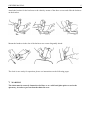
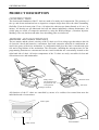
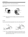
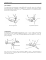
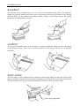
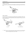
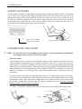
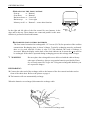
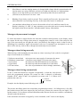
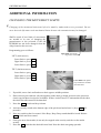
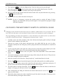
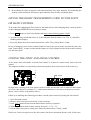
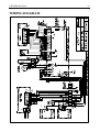
OWNERS’S MANUAL
FM211-1-5
File: Tuoli_E.doc
2.2.2001
OWNERS’S MANUAL
F 1 PATIENT CHAIR
FOREWORD ............................................................................................................................................................................ 2
UNPACKING AND ASSEMBLY OF FIMET F1 DENTAL CHAIR ............................................................................. 3
PRODUCT DESCRIPTION ................................................................................................................................................... 6
CONSTRUCTION................................................................................................................................................................. 6
MOTORS AND ELECTRONICS......................................................................................................................................... 6
THE POWER SUPPLY AND MAINS SWITCH ................................................................................................................ 7
FUSES.................................................................................................................................................................................... 7
HEADREST........................................................................................................................................................................... 8
ARMRESTS........................................................................................................................................................................... 8
BACKREST........................................................................................................................................................................... 9
LEGREST .............................................................................................................................................................................. 9
KNEE ANGLE ...................................................................................................................................................................... 9
SWIVEL ACTION............................................................................................................................................................... 10
SEAT ANGLE...................................................................................................................................................................... 10
SAFETY FEATURES......................................................................................................................................................... 11
CONTROLLING THE CHAIR........................................................................................................................................... 11
Foot control .................................................................................................................................................................... 11
Hand control.................................................................................................................................................................... 13
Joystick............................................................................................................................................................................ 13
PROGRAMMING.................................................................................................................................................................. 14
USING MEMORY POSITIONS......................................................................................................................................... 14
ASEPTIC CONTROL AND HYGIENE ............................................................................................................................. 14
SERVICE AND MAINTENANCE....................................................................................................................................... 15
THE BACKREST MOTOR AND ITS MECHANICS....................................................................................................... 15
THE MOTOR FOR THE LIFT MOVEMENT.................................................................................................................. 15
PRINTED CIRCUIT BOARD AND SAFETY SWITCH.................................................................................................. 15
SPECIFICATIONS ................................................................................................................................................................ 16
ERROR CODES AND MESSAGES OF SELF DIAGNOSTIC PROGRAM.............................................................. 17
ADDITIONAL INFORMATION.......................................................................................................................................... 19
CHANGING THE MOVEMENT LIMITS......................................................................................................................... 19
CHANGING THE MOVEMENT LIMITS IN JOYSTICK CHAIR.................................................................................. 20
GIVING THE RIGHT TRANSMISSION CODE TO THE FOOT OR HAND CONTROL ........................................... 21
CODING THE FOOT AND HAND CONTROL............................................................................................................... 21
PACKAGE POSITION........................................................................................................................................................ 22
0-POSITION ........................................................................................................................................................................ 22
CHANGING THE FACTORY PROGRAMMED 0-POSITION...................................................................................... 22
SPITTOON PROGRAM ..................................................................................................................................................... 22
TROUBLE SHOOTING........................................................................................................................................................ 23
PRINCIPLE OF EPROM MARKINGS............................................................................................................................. 23
TO REDUCE NOISE LEVEL AT MOTOR ...................................................................................................................... 24
TIGHTENING THE LOOSE POTENTIOMETER LOCKING SCREW......................................................................... 24
TWO OR MORE CHAIRS MOVING BY THE SAME REMOTE CONTROL ............................................................. 24
WIRING DIAGRAM.............................................................................................................................................................. 25
DIMENSIONS......................................................................................................................................................................... 26
RECOMMENDED INSTALLATION................................................................................................................................. 26
Fimet Oy reserves the right to change specifications without prior notice.
All rights reserved
Copyright Fimet Oy
FM211-1-5
File: Tuoli_E.doc
2.2.2001
OWNERS MANUAL
2
FOREWORD
Our congratulations on the decision to invest in high quality F1 patient chair. We wish that your
work with it will be enjoyable and problem free.
Fimet F1 chair is electrically controlled, multi-functional patient treatment chair for medical
purposes. Because of its flexibility, it can be used not only as a Dental chair but can be modified to
be used also as an ENT, Ophthalmology and Podiatry patient chair. It can be used as well for barber
and cosmetology applications.
This well-designed chair is also easy to use. For example the armrest can swing out, so it is easy to
get into the chair, and thereby make it easier for elder or invalid patients. Because the whole chair
top can be rotated, it is also easy to use it in a small room.
The chair is controlled by remote foot- or hand control. In some applications two fixed joystick type
foot controls are also available. The microprocessor inside of the chair is controlling the chair and
performing self diagnose of itself constantly. It is possible to store eight working positions in the
chair’s memory. The whole control system as well as the motors run on 24 volts, which makes the
chair absolute safe for both patient and the doctor
It is possible to select from various color possibilities; an appropriate combination that suits the
room colors. The chair’s upholstery has been designed to minimize the amount of seams and
thereby maximize hygiene. The upholstery can be of polyurethane, vinyl or genuine leather. The
upholstery is easy to clean and, if necessary, replace.
OWNERS MANUAL
3
UNPACKING AND ASSEMBLY OF FIMET F1
DENTAL CHAIR
Unpack the chair from the transportation box and check that all parts are enclosed and undamaged.
Contents:
o Owners manual
o The chair
o Backrest with bracket
o 3 Allen screws for backrest bracket
o Power supply with mains cord
o Headrest with bracket
o 2 armrests
o 2 covers for armrest holder
o Foot rest
o Foot control
Check that the voltage marked on the power supply
corresponds to the voltage of your mains outlet.
Power supply
Contents
Connect the chair to the power
supply by means of the
multiconnector plug
8 pole connector
OWNERS MANUAL
Open the rear end of the foot control by bending the
soft cover upwards and gain thereby access to the
rechargeable batteries. Connect the batteries and fold
back to cover. Charge the batteries before use (see
page 12)
If there is a unit:
Remove the upholstery by undoing the locking
rings at the armrest attachments by means of
rotating the plastic locking ring anticlockwise. Lift
the upholstery upwards and slide forward.
Remove the sheet metal by opening two screws
and pull the plate away. Connect the wires coming
from the F1 E unit color-to-color in terminal block
and attach the flat cable in it’s counterpart.
Connect the power supply in a grounded wall socket.
Be sure that the voltage rating is same in the wall
socket and in power supply.
Turn on the power by means of the switch on the
power supply. The green pilot lamp will now light up.
Wait approx. 30 seconds before operating the chair.
The built-in microprocessor checks that all functions
and controls are in order.
If there is a unit:
Raise the chair approx. 15 cm (6 inches) by means
of the foot control (push the right-side button for
lift) and fit the unit in its adapter iron located
beside and below the chair seat. Adjust the
position of the unit by using adjustment screws in
the adapter iron and tight the unit firmly in its
place. (Refer to a separate “Quick Installation
Quide”.
Restore upholstery and lock it in its place by using
plastic locking rings.
Attach the armrests to the chair.
4
OWNERS MANUAL
5
Attach the bracket for the backrest to the chair by means of the three screws and slide the backrest
on the bracket.
Mount the headrest in the slot of the backrest one corner diagonally ahead.
The chair is now ready for operation, please see instructions on the following pages.
∇
WARNING!
The chair must be securely fastened to the floor or to a solid steel plate prior to use in the
operatory, in order to prevent that the chair tilts over.
OWNERS MANUAL
6
PRODUCT DESCRIPTION
CONSTRUCTION
The chassis and foundation of the F1 chair are made of a sturdy steel construction. The geometry of
the up- and down mechanism has an ingenious compact design that offers the chair outstanding
flexibility. From its lowest point 35 cm ( 14 inches) the chair moves almost linearly to 91 cm ( 36
inches). All bearing are pre-lubricated and will last almost indefinitely without maintenance. All
visible parts are made of composite materials by using the RIM technique ( Reaction Injection
Molding). The seat, backrest and other force absorbing parts are reinforced.
MOTORS AND ELECTRONICS
The two motors and the electric circuitry of the F1 chair are of low voltage type that reduces the risk
of electrical shock and hazard to a minimum. Steel and composite materials in combination are
used in the gears of the drive mechanism. A configuration that gives the chair a smooth and quiet
ride and a long lifetime of the mechanism. The electronics, including the microprocessors for the
programming functions are concentrated on one circuit board that are conveniently located on the
right hand side of chair. All major components of the F1 chair are easily accessible for fast and
convenient service and maintenance.
Safety switch:
All movement will
stop when the rear
is lift upwards
Backrest motor
Lift motor
Recharge connector
All functions of the F1 chair are controlled by means of a cordless foot control that meet the
individual needs of convenience.
Control panel
Batteries
Safety switch
Foot control
OWNERS MANUAL
7
THE POWER SUPPLY AND MAINS SWITCH
The transformer, the rectifier, the mains switch and the fuses are all housed in a separate power
supply box, apart from the chair for improved safety. Always turn off the mains switch when the
chair is not in use.
Power switch
Fuses
Pilot light
F NOTE!
Connections
Power cord
When switching on the mains, wait approx. 30 seconds before operating the chair.
The built-in microprocessor is checking that all functions and controls are in order.
(Self diagnostic)
FUSES
The fuses (T 2 A) are housed in the power supply box and are easily accessible. If the power supply
is located in the Floor Box (in firm installation), there is only one fuse, otherways always 2 pcs.
F NOTE!
There is a overheating protection switch built-in to the power supply box. In case
where the transformer overheats the overheat protection switch will cut the circuitry
to the chair immediately. When the transformer cools down the safety switch will
automatically go back to its on position. When overheat protection is functioning the
display of the chair indicates H (Hot).
OWNERS MANUAL
8
HEADREST
The compact headrest has an anatomic design and offers the best possible support while holding the
head firmly in place. By releasing the lever on the left side, the headrest can be adjusted to almost
any desired position. The headrest is also easy to adjust longitudinally up to 20 cm by moving it in
and out of the slot in the backrest.
Position adjustment
Longitudinal adjustment
ARMRESTS
The armrests can be turned 90 degrees sidewards and are easy to remove in order to provide better
access and make it easy for elderly or disabled people to get in and out of the chair. To turn the
armrests, lift approx. 2,5 cm (1 inch) and turn towards desired direction. Remove the armrest by
pulling it straight up.
There are two covers provided with the chair which should be placed in the armrest holders if
armrests are not used. As an option, there are two extra arm supports available that can be attached
to the sides of the backrest.
OWNERS MANUAL
9
BACKREST
The backrest can be extended up to 10 cm in order to accommodate any patient. To adjust the
length just push the button on the lower part of the backrest and move the backrest in the desired
direction. Don’t let the backrest fall without restrain, support it with hand. Release the locking
button after locking position is found.
LEGREST
The legrest is extendible up to 10 cm, (4 inches). In order to adjust the length, just move the legrest
to the desired position. There are two locked positions for the legrest, all the way in and fully
extended.
KNEE ANGLE
The knee angle is easily adjusted into two different positions. By lifting the front end of the legrest
and by pressing the foremost release button simultaneously the angle can be increased or decreased.
The movement of the legrest is synchronised with the backrest as well as the knee angle.
Knee angle adjustment
OWNERS MANUAL
10
SWIVEL ACTION
The F1 chair rotates ± 90 degrees from its neutral position. To turn the chair, open the locking lever
on the right side of the chair and turn the chair by hand to the desired angle. Lock the lever when
done.
Swivel lever
SEAT ANGLE
The angle of the seat can be adjusted into two different positions. By pushing the middle release
button on the right side of the chair and pushing the backrest with other hand the seat is released
and can be adjusted. Note that this adjustment must be done without patient. The angle of the seat is
synchronised with backrest.
Seat angle
F
Trendelenburg position
NOTE! In the event of an emergency the chair can be moved into the so called Trendelenburg
position by pushing the middle button and flipping the chair backwards. The chair
must be in a horizontal position in order to do this.
OWNERS MANUAL
11
SAFETY FEATURES
A safety switch is located on the printed circuit board on the right side under the chair. If something
(e.g. a foot) come in between the lifting mechanism and the base of the chair when the chair is in
motion, this safety switch will immediately stop all movements. The chair can be restarted as soon
as whatever caused the stop has been removed. For improved safety the foot control also works as
an emergency stop switch. Hit any of the control switches of the foot control when the chair is in
motion and all movements of the chair stops immediately.
Safety switch. Activated
when rear is lift upwards.
Activate any button for emergency stop
CONTROLLING THE CHAIR
F NOTE!
If some other device is disturbing wireless remote control transmission, immediately
start using remote controls with recharge cable.
FOOT CONTROL
All movements of the F1 chair are controlled by means of the cordless foot control. The foot
control contains all functions for the manual operation of the chair. It can be used also for
controlling F1 unit options. In addition, the foot control is used for programming and activating
different pre-set working positions. Transmission of the electro-magnetic signals between the foot
control and the chair is accomplished by means of inductive fields. In cases when you have more
than one F1 chair in your office the foot controls have different codes in order to prevent any
interference.
The foot control is operated by rechargeable accus size AA. To charge the accus just connect the
foot control to the cord that is provided with the chair. In the event of malfunction in the cordless
transmission, connect the cord used for charging the accus to the foot control. This will override
the cordless transmission, and the chair can now be operated as usual. Do not use normal
batteries instead of accus in the foot control!
F Hint:
If accus have exhausted, the chair can be operated as normally with recharge cable.
3
2
Lever
1
Batteries
OWNERS MANUAL
12
OPERATION OF THE FOOT CONTROL
Seat up:
⇒
Seat down:
⇒
Backrest down: ⇒
Backrest up: ⇒
Memory recall ⇒
Button 1
Button 3
Lever left
Lever right
Button 2 + some other function
In the right and left sides of the foot control lies two buttons; in the
edge and on the top. These buttons are connected parallel so the same
function is performed from both buttons.
3
DOWN
2
1
UP
RECHARGING FOOT CONTROL BATTERIES
The foot control contains four rechargeable 1.2 V accus (Ni-Cd) for operation of the cordless
transmission. Recharging time is about 24 hours. Typically recharging must be performed
three to six week intervals. If there is also F1 E unit attached, the need of recharge is
increased. When the display on the back of the chair indicates A, it means the accus need to
be recharged. If the chair is operated during recharging process the recharge time is longer.
∇
WARNING!
Do not replace the rechargeable accus delivered with the chair with any
other type of batteries. Always use genuine batteries provided by Fimet
Oy or exactly same Ni-Cd type AA. Using non rechargeable batteries you
are exposed to danger!
RECHARGING:
o Connect the other end of the recharge cable to the bottom of the foot control and other end to
front of the chairs base. Refer to the picture on page 6.
o The batteries will now automatically recharge.
When the batteries are recharged, disconnect the recharge cable.
Connection of recharge cord
OWNERS MANUAL
13
HAND CONTROL
Manual: Backrest up
Automatic: 0-position (exit postition)
Manual: Chair up
Automatic: Upper working position
Manual: Backrest down
Automatic: Lower vorking position
Manual: Chair down
Automatic: Recall of the previous position
Pushing this button again causes the chair to go
back in to that position where it was before first
pushing.
Position recall: Push here and within three
seconds any button marked with an arrow and the
chair will move automaticly in preprogrammed
position.
F1 ja F2
Used only in some special modified chairs.
Recharging
connector
The hand control does not need to be pointed towards the chair like for example tv:s remote
control because hand control works with different principle. The range is about 2 m and it works
best when held in horisontal position in hand.
Hand control has same kind of coding system like foot control. When the chair is controlled with
both hand and footcontrol, they must possess the same coding.
RECHARGING HAND CONTROL BATTERIES
Connect the provided recharging cable in to the connector located in the other end of the hand
control and the other end to the recharge connector located back at the chairs base part.
Some chairs have separate holder for the hand control which has recharging function built-in.
Just place the hand control in it’s holder and it will recharge automaticly.
JOYSTICK
The third way to control the chair are joysticks. Joysticks are firmly positioned to the base of the
chair and are easy to operate to the doctor and nurse.
BACKREST UP
LEFT
RIGHT
BACKREST
DOWN
CHAIR DOWN
CHAIR UP
CHAIR DOWN
Manual use:
Turn joystick in desired position to drive the chair
Recall position:
Turn the joystick shortly in to that direction where the desired
position is saved and release it to middle position. The chair beeps
shortly after succesfull recall-action.
OWNERS MANUAL
14
PROGRAMMING
The chair has eight memory places for different positions, four places for user A and four places for
user B. Memory positions are stored as double actions in control buttons.
F1
FIMET OY FINLAND
USER A
CODE
USER B
USER
PROG
Chair’s back panel
o Select user / operator (A/B) by pushing
Programming button (PROG)
User selection A/B (USER)
Display
USER
o Drive the chair to the desired position
o Push the PROG button on the back panel of the chair, release it and within 3 seconds select the
memory place by selecting one of the buttons of the foot (or hand) control or by moving
joystick. The program is now saved.
o Repeat the procedure in order to program other working position in the next memory place.
(Memory place lever-right is programmed at the factory and can’t be changed usual way.)
o Change user / operator by pushing USER again. The user B -light will flash. Repeat the
programming procedures as for user A.
USING MEMORY POSITIONS
Use the desired preset working position by pushing the PROG -button of the foot (or hand-) control
once and within 3 seconds select the memory place you want use. When the chair is running, all
movements can be stopped at any time by activating any button or lever. The safety switch also
stops all chair movement.
Programming succestion:
Lever right:
Lever left:
Left button:
0-position (programmed at factory)
working position
rinse position
Memory position left-button is also called as ”rinse position”. Program this memory place so that
the chair moves into a position whereby it is convenient for the patient to rinse. Use the function by
pressing first PROG -button and then left (rinse) button of the foot control. Return to the original
position just by pressing the “rinse” button again.
ASEPTIC CONTROL AND HYGIENE
All surfaces of the F1 chair are smooth and the upholstery is without seams for improved hygienic
properties and aseptic control. The polyurethane parts are easy to wipe clean with your regular
detergent, alcohol or other disinfectants. Fimet recommends “Super Blue” -detergent adulterated to
2…4 % strong liquid. Plastic parts, such as chair’s base cover, is best to clean with soap and water
or with dish washing liquid.
OWNERS MANUAL
15
SERVICE AND MAINTENANCE
F
NOTE! The warranty expires and Fimet Oy declines all responsibility if somebody else but
Fimet Oy's authorised service course passed qualified serviceman maintain or repair
this device
THE BACKREST MOTOR AND ITS MECHANICS
To gain access to the backrest motor:
o Remove the armrests and the locking rings that holds the upholstery in place
o Lift the upholstery carefully off the armrest holders and slide it forward of the chair
o Remove the two screws that holds the metal cover in place, and remove it
o The motor and the mechanics of the backrest as well as the mechanics of the control buttons are
now easily accessible
THE MOTOR FOR THE LIFT MOVEMENT
The motor for the lifting mechanism is accessible from the front of the chair.
o Remove the four screws that holds the cover on place.
o If the chair is being serviced for the first time the plastic cover needs to be cut open. Use a sharp
knife and cut both sides along the grooves from bottom to top.
o Fold the plastic cover carefully upwards. The motor is now accessible for service.
PRINTED CIRCUIT BOARD AND SAFETY SWITCH
The printed circuit board and the safety switch are located on the right hand side of the chair next to
the lift mechanism. To gain access, remove the plastic cover by releasing the front corner that snaps
over the metal guide, and then cranking it off carefully. Slip display panel through back cover hole at
the same time. The plastic cover and the bellows are inter connected by means of mechanical
retention and are easily separated. When the cover is removed from the chair the circuit board is
easily accessible for service.
OWNERS MANUAL
16
SPECIFICATIONS
Fimet F1 chair
Mains connection
The separate power supply connects to:
230 V ±10 % 50 Hz or 110 V ±10 % 60 Hz
Electrical data
24 VDC low voltage motors
Microprocessor controlled, self diagnostic
Chair operates at 24 V DC 450 VA
Humidity
Operating: 30 - 75 %, storage & transportation: 10 - 100 %
Temperature
Operating: +10 - +40 ºC, storage & transportation: -40 - +70 ºC
Protection against electric shock
Class I
Protection against liquids
Drip-proof IPX I
Operation mode
Continuous operation with short-time loading
Fuses
T 2 A two pieces
Mounting
To be fixed to the floor or heavy metal plate
Chassis
Welded steel frame. All visible parts cast in composite material
Max lift weight
180 kg or 400 Lbs
Net weight
110 kg or 240 Lbs
Upholstery
Upholstery, headrest and armrests cast composite material.
Additional materials on demand.
Movements
Seat height max. 91 cm or 37 inches, min. 35 cm or 14 inches
The initial seat height adjustable 10 cm or 4 inches by factory
Backrest angle 90°
Rotation ± 90°
Trendelenburg angle 9°
In the case of problems please contact retailer. The manufacturer will assist also if required.
Fimet Oy
Teollisuustie 6
FIN 07230 Monninkylä
Phone +358 19 521 6600
Fax
+358 19 521 6666
E-mail: [email protected]
OWNERS MANUAL
17
ERROR CODES AND MESSAGES OF SELF
DIAGNOSTIC PROGRAM
When the microprocessor of a F1 chair detects a fault it tries to inform about the most probable
reason. The error code is showed on the display of the chairs rear panel.
Starting from program version 6A.8B the program version is showed on the display when power to
the chair is switched on. This information can also be helpful when trying to find reason for a
problem.
In error codes there are two numbers (shown after each other) and the numbers are showed twice.
Error codes which start with number 1 are for lifting motor, 2 is for backrest motor and error codes
starting with 5 are for potentiometers.
It must be noticed, that no matter what error code is shown, the reason might be elsewhere.
Example: Fault code 50. A wire to the potentiometer of the lifting motor is broken or the
potentiometer is defective. The problem might be on the main pc-board, wires, on a terminal
connector, connector between the wires and pc-board, connector between the wires and
potentiometer or the potentiometer.
In case several problems occur at the same time the processor informs about the problem, which has
lowest number, for example when the voltage is low, the showed error code is 10 (not 20).
Error codes
10, 20: Low voltage (or missing) for motors
12:
A wire to the lifting motor is broken
13:
Wires to the lifting motor are shorted
22:
A wire to the backrest motor is broken
23:
Wires to the backrest motor are shorted
50,51: A wire to the potentiometer of the lifting motor is broken or the potentiometer is defective.
52,53: A wire to the potentiometer of the backrest motor is broken or the potentiometer is defective.
If the potentiometers are mechanically turned to its maximum or minimum values, these
same codes are displayed.
54,55: Lift (54), backrest (55): Movement limits too near each other or too near mechanical limit
{from ver. 6A8B6}
56,57: Lift (56), backrest (57): Some unlogic in the limits (e.g. upper limit < lower limit) {from ver.
6A8B6}
11, 14, 15, 16, 21, 24, 25, 26: Main printed circuit board is defective.
E, EE: (EEPROM) EEPROM is defective. Error message E is shown also when a position is tried to
be stored on channel 1 ( backrest down).
U:
(Unit) Unit-adapter is connected to the chair, but the main processor can't get any reply from
the unit. Same error message comes, if instrument is picked up before turning power on.
Notice, that after "U"-error, the unit can't be used. Before power is switched OFF or safety switch is shortly activated.
OWNERS MANUAL
H:
8:
18
(Hot) Motor is too hot. Analog memory is charged with voltage which is proportional to the
current motors are using. When the current is too high too long time it is supposed that
motors are too hot and to prevent motors to be destroyed the current is turned off.
(All leds are on) Processor is in reset - state.
0:
Blinking (Zero) Safety switch is pressed. This is actually no Error-code, but means, that
microcontroller is not working correctly. At the same time buzzer is usually on.
A:
(Accumulator) when charge of accus is decreased to a low level (and foot control is on)
display is showing "A" (this "A" may sometimes occur also when noise is partly destroying
the signal so that microcontroller "misunderstands" battery information).
Messages why movement is stopped
If chairs movement is stopped before the chair has reached wanted position, to the display comes
the reason for the stop. Always when motor is stopping there comes a code of the reason for the
stop. If the movement was all right the code is not showed. One thing to notice is that if noise is
disturbing foot controllers signal, microcontrol can't say if command was interrupted or not. So
there will be not any code to show, though movement stop was not natural.
Messages when driving manually
When driving a chair manually only one motor at a time is moving. Used codes for exceptional
stops of movements are as follows:
5: Software current limit
6: Hardware current limit
7: Lower limit,
8. Upper limit;
9: No movement;
microprocessor stops supply of current to the motor
electronics stops supply of current to the motor
the chair has reach the minimum level (soft limit)
the chair has reach the maximum level (soft limit)
the value of potentiometer doesn't change (automatic)
16 A
9A
8A
Messages when driving automatically
If one or both movements are stopped exceptionally, so that the chair doesn't
reach the programmed position, the reason for that is showed in following
formula: 1X2Y: where X and Y are replaced by a reason code 5 - 9. If there is no
problem the code is 0.
1 = Liftmotor
7A
2 = Tiltmotor
Example: into the display comes following code 1025.
This means, that lifting motor has reached the programmed position (1 for lifting motor, 0 for OK),
but backrest motor has been stopped by the processor, because the current was too high (2 for
backrest motor, 5 for software current limit downwards). Reason for the error could be a mechanical
obstacle under the backrest.
If the automatic movement is stopped by a new command, code F comes to the display.
OWNERS MANUAL
19
ADDITIONAL INFORMATION
CHANGING THE MOVEMENT LIMITS
G
Changing of the movement limits must left to be made by authorized service personnel. Do not
never drive the lift motor to the mechanical limits because the transmission may be damaged.
Shall be made if new limits of movements
are needed or in case of changing the
potentiometer or the pc-board, if the old
EEPROM has not been changed from the
old pc-board to the new one.
Programming goes as follows:
LIFT: (chair moves)
Upper limit when metal
ring comes visible
Lower limit ⇒ press USER
Upper limit ⇒ press USER
Lower limit ⇒ press USER
TILT: (backrest moves)
Lower limit ⇒ press USER
Upper limit ⇒ press USER
Lower limit ⇒ press USER
Lower limit when plastic
strip reaches the urethane
part of the base
1.
If possible, move chair and backrest to their approx. middle positions.
2.
Short-circuit 6-pin connector (all pins together) at the chair-pc-board just next to the processor
circuit (special short-circuit piece available). If there is also Fimet F1 E unit attached to the chair,
the other flat cable must first be detached.
3.
Press the
4.
Activate security switch at the bottom edge of the pcb-board and release it. (keep
pressed))
5.
Press any switch at the foot control. Now Beep, Beep, Beep sound should be heard. Release
PROG -switch and foot control.
6.
Chair goes now downwards (it can only be stopped at the security switch or at the mains
switch).
Press the USER -switch at the desired lowest limit. Now the chair start going upwards.
7.
PROG
-switch and keep it down
PROG
still
OWNERS MANUAL
20
8.
Press again the
9.
Press once again the USER -switch exactly at the same lowest limit than first time. Now the
lowest and highest limits are set and the chair stops at this position.
USER
-switch at the highest limit. Now the chair goes downward again.
10. Backrest starts moving. Set the limits for backrest at the same way described above by pressing
the USER -button at the limits.
11. When limits are set, remove the short-circuit piece.
F NOTE!
In case of emergency, activate the security switch or switch off mains. If these
happens you must make whole procedure again. It is not possible to program a single
limit but all together.
CHANGING THE MOVEMENT LIMITS IN JOYSTICK CHAIR
G
Changing of the movement limits must left to be made by authorized service personnel. Do not
never drive the lift motor to the mechanical limits because the transmission may be damaged.
The programming procedure described here is only advisable to be made by this way when there
is no foot or hand control! Refer “Changing the movement limits” above.
1.
Carefully remove the back urethane of the chair. Release the display panel and slip it through
the hole in the urethane to the other side.
2.
Unscrew two screws of the plastic microprocessor case which held the top cover in place.
Examine carefully how the emergency switch, spring and other associated parts are constructed
together.
3.
Locate 6-pin flat cable at the right side of the processor circuit and joystick adapter pcb at the
main pcb. That cable is later to be removed and replaced by short-circuit piece.
Press down the PROG -button at the rear panel of the chair and KEEP it down until further
notice.
4.
5.
Activate the emergency switch on the bottom edge of the main pcb and release it. The processor
now starts waiting for joystick-command.
6.
Move the joystick to any direction. “Beep beep beep” -sound should now be heard.
7.
Release the
8.
Now there is 12 seconds to remove the 6-pole flat cable and replace it with short-circuit piece. If
the time runs to the end, the whole procedure must start all over again.
9.
The chair starts to moving downwards. Use the USER -button to mark the limits as described in
chapter “Changing the movement limits” on page 19.
PROG
-button from the back panel of the chair and joystick to its middle position.
10. After setting limits for lifting, the backrest movement limits must be set too. Use
again to set the limits.
USER
-button
11. Detach the short-circuit piece and re-install the 6-pole flat cable in its place. Check those new
movement limits by driving the chair to them.
OWNERS MANUAL
21
12. Re-assembly the chair in opposite order than dismantle. Pay extra attention for assembling the
security switch and check its behavior again when the chair is fully assembled again.
GIVING THE RIGHT TRANSMISSION CODE TO THE FOOT
OR HAND CONTROL
To be made after changing the foot control or the hand control, after changing chair’s main pc-board
or after changing EEPROM circuit in main pc-board.
1. Press
PROG
-button in chair’s back panel and keep it pressed during points 2 and 3
2. Activate security switch and release it. (Lift back panel from the chair’s rear. The “0” should be
blinking on the display).
3. Press any button from foot control and release it after ”Beep, Beep, Beep” sound.
In case of bringing a new remote control (hand or foot) to the system, make sure that they have the
same ”hard-coding”, in other words, that the jumper in 10-pin jumper block of both remote controls
is in the same place.
CODING THE FOOT AND HAND CONTROL
To be made when afterwards accuired hand control is wanted to control same chair with foot
control.
The simpliest method is to open both controls and organize short circuit pieces at the same way
1
2
3
4
5
12345
In most cases, opening of the foot control can be avoided, because the code is written in the bottom
of it. The code can be for example“2-3”, which means that there is two short circuit pieces used in
places 2 and 3. (Refer to the picture above.)
If there is no marking, the following procedure can take place instead of opening the foot control:
1.
2.
3.
4.
5.
Open the hand control
Remove short circuit pieces from the 10 pin connector
Push PROG -button down from the hand control and keep it pushed
With a screwdriver make a short circuitry between 1-1, 2-2,...5-5
Put the short circuit piece in that place where the chair makes a ”Beep” sound
If there are 2 short circuit pieces at the foot control, the above mentioned doesn’t work. In this case:
OWNERS MANUAL
22
6. Put the short circuit piece to place 1-1. Keep the PROG -button pushed down.
7. With a screwdriver, make a short circuitry between 2-2, 3-3, 4-4, 5-5.
8. If no ”Beep”-signal, put the short circuit piece to 2-2, and make a short circuitry with a
screwdriver to 3-3, 4-4, 5-5 etc.
PACKAGE POSITION
In order to place the chair in its package, the chair can be driven below its lowest position. Press
USER -switch (from back panel of the chair) and at the same time press ”chair down” switch at the
foot control.
F NOTE!
Chair’s backrest must be at the package position also.
Don’t drive the chair at it’s mechanical limit.
0-POSITION
Since 12.12.1990 there is 0-position or exit position firmly programmed at the factory. This position
is recalled by pressing PROG -button from the foot control and activating “backrest-up” -function.
0-position:
PROG
+ backrest up.
CHANGING THE FACTORY PROGRAMMED 0-POSITION
Drive the chair to the desired 0-position (exit position).
Push first PROG (from back panel of the chair) and then
turn foot control lever rightwards.
USER
so that both remain pushed down and
SPITTOON PROGRAM
This program works when foot controls middle button ( PROG -button) is pressed and within three
seconds the left corner button. Pushing left button again brings the chair in it’s original position.
The spittoon position is programmable like any other position.
OWNERS MANUAL
23
TROUBLE SHOOTING
Twitching backrest
Chair’s backrest is moving down but it always stops after few centimeters when manually driven
but moves correctly when automatically driven.
Solution:
The reason is at the electric current limit, which is all the time checked by the processor. The
backrest motor takes too much current. In chairs, which have been moving correctly before, this is
due to the gradual stuck of the backrest motor. Current to correct functioning motor is between 2
and 4 A, and is limited in downward moving to 7 A.
If there are other disfunction as well (lift motor is cutting off as well), the reason may be in remote
transmission.
Measures:
o If the reason seems to be the remote control, try to drive the chair with recharge cable connected.
If other hand or foot control is available, try with it. (Remember to put the same ”hard code” for
the new remote control).
o Check the gears by eye, that they are in condition. If not, change the complete motor.
o Put a little bit of white grease on the drive screw.
o If it doesn’t help, check next that the case of the motor hasn’t moved from its place; check that
the motor fitting screws are tight. There is the possibility, that the rotor is sticking with the field
magnets; knock slightly the motor itself with a soft hammer to free the sticking rotor.
o If it doesn’t help, put little bit oil on the brake.
o The failure can be at the measuring of current on the main pc-board. Change the pc-board.
o If it doesn’t help, change the complete backrest motor.
Current limits:
Lift 16 A
Tilt 7 A
PRINCIPLE OF EPROM MARKINGS
For instance the marking 6A.8B3
Marks left from the point are for ”hardware”, right for ”software”.
Old EPROM could always be replaced by a new one presuming new software version is same or
newer. For instance, 6A.8B3 could be replaced by 6A.8B8
OWNERS MANUAL
24
TO REDUCE NOISE LEVEL AT MOTOR
The noise may be reduced by slightly changing the position (angle) of the motor to its fitting plate.
This is done by slightly tightening the other M6 screw and by loosening the other (appr. half a
round). It may be necessary to slightly loosen the ∅ 6 screw in the middle and to tighten it again.
6
6
M6
M6
φ 32
G
Do not try to adjust the motor unless really necessary.
TIGHTENING THE LOOSE POTENTIOMETER LOCKING
SCREW
In some older F1 chairs following failure has been found:
There is irregular problems in backrest movement by manual or/and automatic operation. The
reason for this can be loose locking screw, witch should lock the ∅ 10 mm steel axle to the backrest
pivot bar. The backrest potentiometer is fixed to this axle and the axle should rotate with the pivot
bar, when the backrest is moving. The head of the locking screw is hidden 2-3- mm under the
polyurethane surface at the end of the pivot bar, see picture. There is a small cut in polyurethane to
reach the screw head.
Tighten the locking screw after having put it in its middle position and set the limits. (The above
described failure is also possible in lift potentiometer.)
TWO OR MORE CHAIRS MOVING BY THE SAME REMOTE
CONTROL
In some cases following problem has occurred, if the dentist has two or more F1 chairs in the same
surgery. When the foot (or hand) control of one chair is activated, the other chair starts also to
move. The reason is following: both chairs have the same transmission code in the remote controls.
Solution:
Open the foot control by loosing the 2 fastening nuts under the foot control and by taking away the
plastic cover. Now there is in sight 2x5 pcs code pins and there is one or more short circuit
connectors (jumpers) between the two lines. Change this coding by changing the place of the short
circuit connectors. If the chair has a remote hand control as well, make the same code into the hand
control after opening it.
To teach the new code to the chair, follow the instruction in ”Giving the right transmission code…”
(page 21). In newer chairs the code number (=places of jumpers) is written at the bottom plate of the
foot control.
OWNERS MANUAL
WIRING DIAGRAM
25
OWNERS MANUAL
26
DIMENSIONS
490
380
190
8
ø1
556
506
506
467
480
600
255
500
380
1
ø1
M5
M10
380
468
Base plate (optional),
thickness 15 mm
RECOMMENDED INSTALLATION
The base of the chair