1
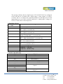
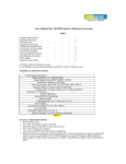
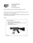
USER MANUAL for Smart Alert Mode VE SA 40 / VE SA 42/VE SA 20/VE SA 22
INTRODUCTION
SMART ALERT (SA) is used for obtaining quick SMS alerts from field inputs. Smart alert
allows upto 4 Potential free inputs to be sensed. For every input, unique separate SMS is sent to
multiple reporting numbers. Maximum upto 10 different persons could be notified with the alert.
Model V E SA40 supports only inputs whereas model V E SA42 allows 2 potential free outputs to
be controlled remotely via SMS. Model V E S A 20 supports 2 digital inputs and 2 analog
inputs with no outputs whereasVE SA22 allows 2 potential free outputs.
FEATURES
¾
¾
¾
¾
¾
¾
12 V DC power supply.
4 number digital potential free alarm inputs with common ground pin (VE SA40/VE SA42).
2 number NO/C/NC outputs (Available in VE SA42/VE SA22).
2 digital and 2 analog inputs (Available in VE SA20/VE SA22).
Built in GSM modem.
Storage of total 10 reporting telephone numbers,.
(Each with 14 digits max)
¾ Buzzer for audible status.
¾ Configuration via preformatted SMS.
¾ Dimensions : 106 x 63 x 45 mm (Excluding connectors and antenna).
INSTALLING THE UNIT
Inserting/ Removing the SIM Card
To insert or remove the SIM Card, it is necessary to press the yellow SIM holder ejector
button with Sharp edged object like a pen or a needle. When this is done the SIM holder
comes out a little, then pull it out and insert or remove the SIM Card. It is very important that the
SIM is placed in the right direction for proper working.
Connecting External Antenna
Connect the external SMA antenna to the male antenna connector of the unit. The frequency of
the antenna should be GSM 850/900/1800/1900. The right Antenna should be used with the
specified frequency otherwise it can affect the communication.
Power Supply – Screw type connector with +12V DC, 2A supply
1
Digital Inputs –
VE SA40/ VE SA4
For these models, connect the potential free contact wires to DI1 ~ DI4 terminals of unit. The
other end of contact can be connected to common GND terminal provided.
VE SA20/ VE SA22
For these models, the DI1 and DI2 are digital inputs. Connect potential free contact wire to
required input and other end to common GND terminal.
AI1 and AI2 are provided for analog inputs. The 4-20mA sensor output should be connected to
AI1 or AI2 terminal and other end is to be connected to GND.
Digital OutputsVE SA42 / VE SA22
These models support two potential free NO-C-NC contacts for each output. The contact
rating is 230V / 5A. So appropriate capacity load can be switched using these outputs.
Whenever unit is powered off, DO status falls back to NC status and is restored to last
condition upon resumption of power.
OPERATION
At power on, unit beeps twice and power LED glows steady. The unit checks for range and
range LED 1 blinks while the unit gets the range. When the range is found, LEDs become
steady. In good range, all 3 LEDs glow. In medium range, only two LEDs will glow and in low
range, only 1 LED will glow.
Unit then starts scanning inputs and report alarm as and when it detects change of input
state.When SMS to activate output is received, it changes the output state.
VE SA40/VE SA42 has 4 inputs DI1 ~ DI4 and a common GND terminal. The four potential
free contacts must be connected to these inputs. The inputs are configurable as NO (Normally
Open) or NC (Normally Closed) inputs in normal condition. When any input changes its state,
SMS for that input is sent to the configured reporting numbers. All numbers are reported one after
another. The unit can send 4 different SMS messages for each input and the English text is also
configurable.SMS text can be max. 120 characters.
For VE SA20/VE SA22 models, AI1 and AI2 are analog channels. Analog inputs can be set
to indicate alarm on crossing low or high levels set in %. Two alarms can be set – Lo alarm and Hi
alarm. When input to that channel goes below low level or goes above high level, alarm SMS
corresponding
to
analog
input
is
sent
to
reporting
numbers.
2
The status of each input channel is sent periodically to the reporting numbers. In this status
message, user gets information of whether channel is in alarm or normal state. The period of
reporting is also configurable from 01 ~ 24 hours. If this value is set to zero, periodic status
reporting is disabled. The instantaneous status can also be obtained on demand by user, by
sending a SMS to the unit.
Any configuration of unit can be done through two authenticated numbers only. These
numbers can be changed at site. At factory shipping time, default number is configured per user
request.
When unit receives pre-formatted SMS messages, it acts per the message command. The
configuration can be changed only through authenticated numbers, where as general status read
can be done through any number.
SMS FORMATS
¾ To set authentication numbers, send sms in below format.
#123A#xx#xx########*
Where xx are the authentication numbers to be set.
At factory shipping time, the default numbers are configured as per customer inputs.
Customer can change authentication numbers through one of these two numbers only.
When these numbers are changed, SMS ‘Authentication number is changed ‘ is
sent to old and new assigned authentication numbers.
e.g. For setting of 1 authentication number to +919089112231, send SMS as
#123A#+919089112231########*
For setting of 2 authentication numbers, send SMS as,
#123A#+919089112231#+919089112501########*
Note: The number should be entered in full with + symbol, country code and then
subscriber number as written in above example.
¾ To set SMS reporting numbers
#1231#xx#xx#xx#xx#xx#xx#xx#xx#xx#xx*
Where, xx is dialing number. Maximum length can be 14 digits for each number.
3
e.g.
#1231#+919871045611#+919871045501########*
will
configure
+919871045611 as first number and +919871045501 as second number. All other
number slots will remain blank.
¾ To set analog low/high levels (ForVE SA20/VE SA22 only).
#1236#AI1L=xx.x#AI1H=xx.x#AI2L=xx.x#AI2H=xx.x*
This format will set low and high levels for analog inputs 1 and 2. AI1L means analog
input1 low level. AI1H means analog input 1 high level. Similarly low and high
levels are set for analog input 2.These levels are set as percentage values.Default
settings are 10.0% to 80.0% for both analog inputs.
e.g.#1236#AI1L=25.0#AI1H=75.0#AI2L=20.5#AI2H=70.5*
So, analog input 1 low and high levels are 25% and 75% and analog input 2 are
set as 20.5% and 70.5%. So when any of the analog input crosses it’s
corresponding levels, alarm SMS is sent to the reporting numbers.
Note: Please follow this message format carefully. Do not use space or any other
special characters in above format.
¾ To set SMS text for each channel
#123M1#Text*
#123M2#Text*
#123M3#Text*
#123M4#Text*
Where Text is the text message for each of 1 ~ 4 inputs respectively. Please note
characters ‘#’ and ‘*’ should not be part of SMS alert text. Maximum text length can
be 120 characters. Default text is ‘Alarm on Channel 1’ for input 1 and ‘Alarm on
Channel 2’ for input 2.
e.g. #123M1#Alarm on channel 1*
This message will set text ‘Alarm on channel 1’ for input channel 1.So, when channel
1 goes to alarm state, SMS ‘Alarm on channel 1’ is sent to all reporting numbers set.
Similarly
alarm
messages
are sent for other
input
channels.
4
Note: For VE SA20/VE
SA22
#123M3#Text* and #123M4#Text*
these messages will set the alarm text for
analog input1 and analog input 2 respectively. Default text is ‘Meter 1’ for
analog input 1 and ‘Meter 2’ for analog input 2.
When the analog inputs goes below or above the set levels, the alarm
message is sent in the format.
AIx:yyyy Alarm:
(Alarm text)
Where, x = Analog input number (1 or 2) and
yyyy = Low or High
e.g If alarm text is set as ‘Meter 1’(through message #123M3#text* format) and
analog input 1 crosses low level,then message will be sent as
AI1:Low Alarm
Meter 1
When the analog input 1 crosses high level, then alarm message is sent as
AI1:High Alarm:
Meter 1
Similarly,if ‘Meter 2’ is the text set (through #123M4#text* ) and analog input 2 is
below or above set levels, then message will be sent as
AI2:Low Alarm:
Meter 2
AI2:High Alarm:
Meter 2
Analog input open alarm
When analog input sensors are removed or made off, then message is sent
in the format as
AIx:Open Alarm:
(Alarm text)
5
Where, x = analog input number (1 or 2).
e.g. If analog input 1 is removed or off, then message is sent as
AI1:Open Alarm:
Meter 1
To set NO / NC status of inputs
#1234#xxxx#aa#bb#cc#dd*
Where x = 0 means NO, 1 means NC and aa, bb, cc , dd are delay in seconds which
can be set for input channels 1~4 respectively. These can take value from 00 to
99 seconds.
e.g. SMS format to set all inputs as normally NO and all input channels for
delay of 90 seconds.
#1234#0000#90#90#90#90*
So if this message format is set, each input channel will report alarm state if
corresponding channel has retained it’s changed state for 90 seconds. Different delays can be
set for each input channel.
SMS format to set Input1 as NC and others as NO.
#1234#1000#00#00#00#00*
All input channels will report the alarm state without any delay.
Default settings for the input channels will be #1234#0000#00#00#00#00* for
VE SA40/VE SA42 and #1234#0011#00#00#00#00* for VE
SA20/VE SA22.
If only NO/NC status of input channels is to be changed without disturbing delay
settings, then message format #1234#xxxx* can be used.
Note: For VE SA20/VE SA22, SMS can be sent as #1234#xx#aa#bb* for 2 digital inputs.
Where, x is NO/NC configuration for digital input 1 and 2. aa and bb are delays in
seconds for digital inputs 1 and 2 respectively.
¾ To set output status.
#1235#xy*
Where x means output number and y means NO/NC status.(Used only for VE SA42/VE
SA22 model)
x = 1 means output 1 and x = 2 means output 2. y = 0
means NO and y = 1 means NC .
6
e.g. #1235#10* will connect C1 to NO1 position and O1 LED will be ON.
#1235#21* will connect C2 to NC2 position and O2 LED will be OFF.
¾ To set periodic status reporting.
#123Hxx*
The status of 4 inputs is sent periodically to reporting numbers by using above SMS
format. xx in the above format represents hours which can take values from 01 to
24.
e.g. #123H01* will set periodic status reporting after 1 hour. So, when this SMS
is received, unit will start send status message after every one hour.
#123H00* will disable the periodic status reporting.
SMS formats to read current configuration in the unit.
For reading the configuration, SMS can be sent from any number. i.e.
authentication is not required. The SMS formats are mentioned below.
¾ To read authentication numbers.
#123RA*
¾ To read the currently configured SMS reporting numbers.
#123R1*
¾ To read configured SMS text.
#123RM1*
#123RM2*
#123RM3*
#123RM4*
¾ To read current NO / NC status of inputs.
#123R4*
(For VE SA20/VE SA22 only first 2 input status are valid, as next two inputs are analog).
e.g. SMS reply from unit as #1234#1000#90#90#90#90* indicates that channel 1 is
configured as NC and all other channels configured as NO. All the input channels are set
for delays of 90 seconds.
7
¾ To read current output status .
#123R5*
(Used only in VE SA42/VE SA22
models).
Unit sends reply in the format #1235#1x2y*, where x is status of output 1 and y is
status of output 2.
x = 0 means C1 is connected to NO1. x = 1
means C1 is connected to NC1.
y = 0 means C2 is connected to NO2. y = 1
means C2 is connected to NC2.
e.g. SMS reply from unit as #1235#1021* indicates C1 is connected to NO1 and C2 is
connected to NC2.
¾ To read analog low/high levels
(For VE SA20/VE SA22
only).
#123R6*
¾ To read periodic status reporting hours.
#123RH*
¾ To read current status of inputs.
#123RS*
When unit receives this SMS, it sends current status of inputs as written in
below example.
e.g.#123S#CH1 NO(NORMAL)#CH2 NO(NORMAL)#CH3 NO(ALARM)# CH4
NO(ALARM)*
This message tells all input channls are configured as NO. Channel 1 & 2
inputs are in their normal state and channel 3 & 4 input states are changed.
For VE SA20, VE SA22, message will include status of two digital inputs and
two analog inputs as shown below.
#123S#CH1 NO (NORMAL) #CH2 NO (NORMAL) #AI1 60.0% (NORMAL)
#AI2 82.0% (ALARM)*
8
This message indicates that two digital inputs of VE SA20/VE SA22 are configured
as NO and they are in normal state. Analog input 1 sensor output is at 60.0%
(13.6mA) and it is in normal state (Assuming default low and high levels of both
analog inputs are set as 10.0% to 80.0% respectively ). Analog input 2 voltage is at
82.0% (17.1mA) and it is above high level.
LED INDICATIONS
LED
NAME
Power
DI1
DI2
DI3/AI1
DI4/AI2
O1
O2
RANGE
Meaning
ON - Unit is powered on.
ON - Input 1 is in alarm state.
OFF - Input1 is in normal state.
ON - Input 2 is in alarm state.
OFF - Input2 is in normal state.
ON - Input 3/Analog Input 1 is in alarm state. OFF
- Input 3/Analog Input 1 is in normal state.
ON - Input 4//Analog Input 2 is in alarm state.
OFF - Input 4/Analog Input 2 is in normal state.
ON - C1 is connected to NO1.
OFF- C1 is connected to NC1.
ON - C2 is connected to NO2.
OFF – C2 is conncted to NC2.
Indicates unit range.
1 LED ON - Low rage.
2 LEDs ON - Medium range.
3 LEDs ON - Good range.
CONNECTOR DETAILS
CONNECTOR NAME
GND
DI1
DI2
DI3 (AI1)
DI4 (AI2)
NO1
NC1
C1
NO2
NC2
DETAILS
Common GND terminal
Input channel 1
Input channel 2
Input channel 3/Analog Input 1
Input channel 4/Analog Input 2
Output1
Output 2
9
P.O Box: 234911, Dubai, UAE
Tel
: +971-4-2955966
Fax
: +971-4-2955977
E-mail : [email protected]