1
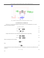
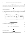
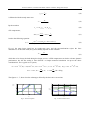
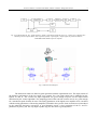
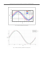
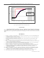
THE PUBLISHING HOUSE
OF THE ROMANIAN ACADEMY
PROCEEDINGS OF THE ROMANIAN ACADEMY, Series A,
Volume10, Number 3/2009, pp. 000–000
IMPROVING THE ACCURACY OF THE ELECTRO HYDRAULIC
SERVOMECHANISMS BY ADDITIONAL FEEDBACKS
Nicolae VASILIU, Constantin CALINOIU, Daniela VASILIU, Dragoş ION-GUTA
University POLITEHNICA of Bucharest, Fluid Power Laboratory, Power Engineering Faculty
313, Independentei, Bucharest, 060042, Romania, Phone: +4021 316 9643, Fax: +4021 316 9645
Corresponding author: Nicolae VASILIU, E-mail: [email protected]
The paper contains a report on some theoretical and experimental researches aiming to create high
accuracy electro hydraulic digital servomechanisms used in high tech applications as actuators, load
simulators, fly control systems, dynamic test machines etc. Computational methods, control software,
design problems, and experimental validation are shortly presented. The authors developed a new
hardware and software solution in order to replace the old generation of two or three stage electro
hydraulic servo valves, and to achieve maximum flexibility of the testing programs. By using one
derivative feed forward path from the system input and one derivative path from the system output the
authors developed a hardware and software configuration that eliminates steady-steady error for step,
ramp and parabolic input. The Keythley ADwin PRO DSP high performance industrial computer and
ADBasic programming language were used. Also, a configuration with PXI Controller from National
Instruments and LabView development environment were used as a very flexible combination. The
experimental researches were carried out on a general-purpose actuator designed and built in the Fluid
Power Laboratory from the University Politehnica of Bucharest. The same ideas were implemented in
different kind of high performance applications as power units speed governors.
Key words: Digital electro hydraulic control systems; proportional valves; control algorithms.
1. INTRODUCTION
A clasical electrohydraulic servomechanism (figure 1) contins a position feedback and a P compensator
only. The dynamic performance is limited by the load mass mainly. An efficient way of improving the overal
damping is the use of an aditional force feedback supplied by a force transducer placed on the piston rod
(figure 2). The transient force feedback is more suitable for a general purpose servomechanism, loaded by a
random force (Lebrun and Claude, 1994). This hardware additional feedback can be replaced by a software
one based on some additional derivative feedback suitable for high speed digital servocontrolers. The general
predictive control by additional state variables feedback leads to good results even with low computation
speed (Mare, 1994).
Fig.1. Basic electrohydraulic servomechanism
Nicolae VASILIU, Constantin CĂLINOIU, Daniela VASILIU, Dragoş ION-GUŢĂ
2
Fig. 2. AMESim® simulation network with aditional force feedback in the loop
2. MATHEMATICAL MODELING
The basic set of equations describing the dynamic behavior of an electrohydraulic servo system
contains the following equations:
Q = K qi i − K qp Pm
V dP
dz
+ aPm + m m
dt
4 E dt
2
d z
dz
Am Pm = M 2 + f
+ F0
dt
dt
Pm = P1 − P2
Q = Am
(1)
(2)
(3)
(4)
Simple transfer functions can be obtained by neglecting the fluid compresibility,
Km
Z (s)
=
I ( s ) s (Tm s + 1)
K mv
Z (s)
H mv ( s) =
=−
F0 (s)
s (Tm s + 1)
H m (s) =
(5)
(6)
and by accepting the practical condition
f ⋅ K ce
Am2
<< 1
(7)
Here,
Tm =
MK ce
Am2
(8)
is the equivalent time constant of the hydraulic motor, including the overal pressure drop influence by the
coefficient
K ce = a + K qp
and
(9)
3
Improving the accuracy of the electro hydraulic servomechanisms by additional feedbacks
Km =
K qi
Am
; K mv =
K ce
Am2
(10)
are the transfer factors on the two control channels. System performance can be derived by the aid of this
model. A proportional compensator ensures a null steady-state error ( εst = 0 ) for a step input signal, yr =
1(t) only. The steady-state error for a ramp input signal
ε st =
1
Kb
(11)
depends on the overal speed gain
Kb = K R Kt K m
(12)
The high level applications as aerospace ones need the elimination of the steady-state error both for
step, ramp and parabolic input signals. This goal can be achieved by the aid of some derivative functional
correction (figure 3), which can be easy implemented by the aid of a high speed IPC (Catana, Vasiliu and
Calinoiu, 1999).
Fig. 3. Servomechanism with derivative corrections
This new configuration is described by the equation
Z (s) =
( K m1 K R + K m1Td 1 s )Yr ( s ) − K mv F0 ( s )
Tm s 2 + (1 + K m1Td 2 ) s + K m1 K R K t
(13)
The system follow error expressed as voltages becomes
ε(s) = Yr (s) − Y(s) = Yr (s) − K t Z(s)
Hence
ε=
[T
ms
2
]
+ (1 + K m1Td2 − K t K m1Td1 )s Yr (s) + K t K mv F0 (s)
Tm s + (1 + K m1Td2 )s + K m1 K R K t
2
(14)
(15)
For a P-compensator,
H RA ( s ) =
U ( s)
= KR
ε ( s)
(16)
and if we apply the condition
Td 1 =
1 + K m1Td 2
K t K m1
the imput ramp steady-state error becomes null for yr (t) = t . The parabolic input signal,
(17)
Nicolae VASILIU, Constantin CĂLINOIU, Daniela VASILIU, Dragoş ION-GUŢĂ
y r (t ) =
4
1 2
t
2
(18)
is followed with the steady-state error
Tm
2 K m1 K t K R
ε st =
(19)
By the notation
a1 = 1 + K m1Td 2 − K t K m1Td 1
(20)
a PI compensator,
H RA ( s ) =
U (s)
1
= K R (1 +
)
ε (s)
Ti s
(21)
leads to the following equation:
ε (s) =
(Tm s 2 + a1 s )Ti sYr ( s ) + K t K mvTi sF0 ( s )
(22)
TmTi s + (1 + K m1Td 2 )Ti s 2 + K m1 K R K t Ti s + K m1 K R K t
3
If a1=0, the ramp input signal has no steady-state error, and the servomechanism rejects the force
disturbances. At the same time, the system stability depends on the condition
Ti >
Tm
1 + K m1Td 2
(23)
which has to be always checked during the design process. A PID compensator can lead to a better dynamic
performance, but the fine tuning is more delicate. A simple numerical simulation can prove the above
considerations. For a typical servo system,
A m = 4 ⋅10 −3 m 2 ; K qi = 0,013m 3 / As; K iu = 5 ⋅10 −3 A / V ; a = 1.2 ⋅ 10 −11 m 5 /Ns; K qp = 0.12 ⋅ 10 −11 m 5 / Ns;
Z max = 0.3m ; K t =
100
Ns
V / m ; f = 1200
; M = 80 kg.
3
m
The figures 4…7, show clear the advantages offered by the derivative corrections.
Yr(V)
Y(V)
4
3
2
2
e(V)
Yr(V)
0
1
0
0
0.5
1
1.5
t(s)
Fig. 4. Clasical response
2
-2
0
0.5
1
t(s)
Fig. 5. Clasical follow error
1.5
2
5
Improving the accuracy of the electro hydraulic servomechanisms by additional feedbacks
g
Yr(V)
Y(V)
p
4
4
e(V)
Yr(V)
3
2
2
0
1
-2
0
0
0.5
eroarea de urmărire
1
t(s)
1.5
Fig.6. Optimised response
2
-4
0
0.5
1
t(s)
1.5
2
Fig.7. Optimised follow error
3. DIGITAL SYSTEM FEATURES
The best solution for fast real time applications is to place a dedicated CPU close to the signal source
and therefore having dedicated resources for the purpose of processing this data. Only this structure gives the
ability of exact response times with predictable delays. If the intelligence is not localized and dedicated, but
centered on a host PC platform, all calculations are under the control of PC’s operating system, Windows,
and its available resources. As a consequence, there can be no guarantees for response times to either an
external event interrupt or an internal timer interrupt. Furthermore, processes executing based on timer
feedback will become erratic, at best, due to inconsistencies in the system timer. However, Windows offers
comfortable user interfaces, multitasking functionality, and great possibilities for network functionality. In
order to take advantages of a Windows environment and run fast and stable real-time processes, it is
necessary to use the ADwin family of products. ADwin real-time systems are complete process controllers
with analog and digital I/O, a local CPU, and local memory (Vasiliu and Vasiliu, 2004, 2005).
ADwin systems use DSP’s, which guarantee response times of as little as 0.5 microseconds to an interrupt,
while maintaining complete software stability, even in a Windows environment. Since the local processor
handles the process control and/or data acquisition, the PC processor is free to run a user interface program,
for example, a man-machine interface with data visualization, user input, data storage, etc., without regard
for the effect the user front-end software has on PC resources. Since the programs runs on the processor of
the ADwin board, up to 10 processes can run simultaneously on one CPU, with priorities assigned where
required. Processes can interact, exchanging parameters and data. Thus, each process has its own
independent timing, but it is also possible to exchange parameters and data with other running processes.
Finally it is possible to develop complex applications with processes, which interact more or less. This is the
case of multiple missiles launcher, aerospace gunnery, ground defenses and other special applications.
4. EXPERIMENTAL TEST
The experimental researches were carried out on a full-scale general-purpose load simulator, and on a
test bench designed and built in the Fluid Power Laboratory from the University Politehnica of Bucharest.
The test bench diagram is presented in figure 8. The digital compensators included in the overall loops are
proportional or PI ones, but any other type like fuzzy can be used. A Stanford signal generator supplies the
input signal of the system. The use of an analog proportional compensator only offers a good dynamics, but
leads to a steady-state error, which strongly depends on the actuator load. This fact was systematic checked
by numerical simulation and extensive experiments. A very simple control system cannot solve the problem
of the accuracy, even for low dynamic requirements. The main characteristics of the test bench are the
following: industrial process computer type ADwin-Pro (KEITHLEY); servo solenoid valves with integrated
amplifier OBE (BOSCH); analog speed/position servo controller AVPC (BOSCH); high speed actuator or
heavy hydraulic cylinder; inductive position transducers (PENNY & GILLES), industrial computer IPC
connected by an Ethernet interface with an industrial process computer. The pressure supply is a constant
one. The control system diagram is presented in figure 8. The dual control system structure designed for high
speed applications is presented in figure 9 (Vasiliu, Calinou, and Vasiliu, 2006).
Nicolae VASILIU, Constantin CĂLINOIU, Daniela VASILIU, Dragoş ION-GUŢĂ
6
Fig. 8. Test bench diagram: SG - signal generator; SVEH – high speed proportional valve; SC – analog servo controller; IPCindustrial process computer; DAS – data acquisition system; i- input signal; e-output signal; PT-position transducer;
ADWinPRO-DSP industrial process computer
Fig. 9. Dual test bench diagram
The theoretical results are found in good agreement with the experimental ones. The improvement of
the dynamic performance of the low speed servo systems for a sine input signal can be identified on the
figures 10 and 11. The overall sine input amplitude was great enough to point out the improvement
introduced by the control algorithm. The sampling period of the real time control was 10 ms, good enough
for a maximum speed of about 45 mm/s. The tuning parameters of the digital error amplifier were correlated
with the tuning parameters of the analog amplifiers included in the systems. Some restriction was introduced
by the numerical derivative corrections. A good dynamics needs a close correlation of the Td1 and Td2
parameters by theory aid. The step input response (fig.12) also shows a good dynamics.
Improving the accuracy of the electro hydraulic servomechanisms by additional feedbacks
1.25
Generator
1
No correction
0.75
Speed correction
0.5
0.25
U[V]
7
0
-0.25
-0.5
-0.75
-1
-1.25
0
1
2
3
4
5
6
7
8
T[s]
Fig. 10. Typical experimental sine input response
Fig. 11. Numerical simulation by AMESim of sine input response
9
10
Nicolae VASILIU, Constantin CĂLINOIU, Daniela VASILIU, Dragoş ION-GUŢĂ
8
2.75
2.7
U[V]
2.65
--- Generator
--- No correction
--- Speed corection
2.6
2.55
2.5
2.45
0
0.5
1
1.5
2
2.5
3
3.5
4
4.5
t[s]
Fig. 12. Typical experimental improved step input response
CONCLUSION
The additional feedbacks are effective, and easy to implement by the aid of modern industrial realtime computers based on the digital signal processing. This new control strategy was successfully
implemented in the new generation of speed governors for hydro power units (Vasiliu, Calinou, and Vasiliu,
2006).
REFERENCES
1.
2.
3.
4.
5.
6.
7.
8.
9.
10.
11.
12.
13.
CATANA, I., CALINOIU, C AND VASILIU, N., (1999), High speed electrohydraulic servosystems, Scientific Bulletin of the
Politechnical University of Timisoara, Tome 44
LEBRUN, M., CLAUDE, R., (1997), How to create Good Models without Writing a Single Line of Code, Fifth Scandinavian
International Conference on Fluid Power, Linköping
LEBRUN, M. (2004), EHA's Model Reduction Using Activity Indexes. Recent Advances in Aerospace Hydraulics, INSA
Toulouse
MARE, J.-CH. (1994), Dynamics of the Electrohydraulic Rotary Servomechanisms, Doctor Thesis, I.N.S.A. Toulouse.
MARE, J.C., CREGUT, S. (2001), Electro Hydraulic Force Generator for the Certification of a Thrust Vector Actuator. Recent
Advances in Aerospace Hydraulics, INSA Toulouse.
VASILIU, N., VASILIU, D., (2004), Electro Hydraulic Servomechanisms with Two Stages DDV for Heavy Load Simulators
Controlled by ADWIN. Recent Advances in Aerospace Hydraulics, INSA Toulouse.
VASILIU, N., VASILIU, D. (2005), Fluid Power Systems, Vol.I. Technical Publishing House, Bucharest.
VASILIU, N., CALINOIU, C., VASILIU, D. (2006), Modeling, Simulation and Identification of the Electrohydraulic Speed
Governors for Hydraulic Turbines by AMESIM. 2006 European AMESim User Conference - 4th Edition, Strasburg
VASILIU D. (1997), Researches on the electrohydraulic servopump and servomotors, Ph.D. Thesis, University
POLITEHNICA of Bucharest
VASILIU N. AND ANTONESCU I., (1998), Hydrostatic Transmission for Aircraft Loaders. AEROTEH Research Report
VASILIU, D., CALINOIU, C., VASILIU, N., (2000), Governing Hydraulic Turbines By Servo Solenoid Valves –Numerical
Simulation And Test, 2000 ESS CONFERENCE, The Society for Computer Simulation, Hamburg
***IMAGINE S.A., (2006). Advanced Modelling And Simulation Environment, Release 4.3.0 User Manual, Roanne
***Servo Solenoid Valves (1999), Technical Specification13/2, BOSCH - Automation Technology, Stuttgart
Received February 16, 2009